WO2024116896A1 - 円筒形電池 - Google Patents
円筒形電池 Download PDFInfo
- Publication number
- WO2024116896A1 WO2024116896A1 PCT/JP2023/041427 JP2023041427W WO2024116896A1 WO 2024116896 A1 WO2024116896 A1 WO 2024116896A1 JP 2023041427 W JP2023041427 W JP 2023041427W WO 2024116896 A1 WO2024116896 A1 WO 2024116896A1
- Authority
- WO
- WIPO (PCT)
- Prior art keywords
- negative electrode
- sealing body
- cylindrical battery
- gasket
- positive electrode
- Prior art date
- Legal status (The legal status is an assumption and is not a legal conclusion. Google has not performed a legal analysis and makes no representation as to the accuracy of the status listed.)
- Ceased
Links
Images




Classifications
-
- H—ELECTRICITY
- H01—ELECTRIC ELEMENTS
- H01M—PROCESSES OR MEANS, e.g. BATTERIES, FOR THE DIRECT CONVERSION OF CHEMICAL ENERGY INTO ELECTRICAL ENERGY
- H01M50/00—Constructional details or processes of manufacture of the non-active parts of electrochemical cells other than fuel cells, e.g. hybrid cells
- H01M50/10—Primary casings; Jackets or wrappings
- H01M50/102—Primary casings; Jackets or wrappings characterised by their shape or physical structure
- H01M50/107—Primary casings; Jackets or wrappings characterised by their shape or physical structure having curved cross-section, e.g. round or elliptic
-
- H—ELECTRICITY
- H01—ELECTRIC ELEMENTS
- H01M—PROCESSES OR MEANS, e.g. BATTERIES, FOR THE DIRECT CONVERSION OF CHEMICAL ENERGY INTO ELECTRICAL ENERGY
- H01M50/00—Constructional details or processes of manufacture of the non-active parts of electrochemical cells other than fuel cells, e.g. hybrid cells
- H01M50/10—Primary casings; Jackets or wrappings
- H01M50/147—Lids or covers
- H01M50/148—Lids or covers characterised by their shape
- H01M50/152—Lids or covers characterised by their shape for cells having curved cross-section, e.g. round or elliptic
-
- H—ELECTRICITY
- H01—ELECTRIC ELEMENTS
- H01M—PROCESSES OR MEANS, e.g. BATTERIES, FOR THE DIRECT CONVERSION OF CHEMICAL ENERGY INTO ELECTRICAL ENERGY
- H01M50/00—Constructional details or processes of manufacture of the non-active parts of electrochemical cells other than fuel cells, e.g. hybrid cells
- H01M50/10—Primary casings; Jackets or wrappings
- H01M50/147—Lids or covers
- H01M50/166—Lids or covers characterised by the methods of assembling casings with lids
- H01M50/167—Lids or covers characterised by the methods of assembling casings with lids by crimping
-
- H—ELECTRICITY
- H01—ELECTRIC ELEMENTS
- H01M—PROCESSES OR MEANS, e.g. BATTERIES, FOR THE DIRECT CONVERSION OF CHEMICAL ENERGY INTO ELECTRICAL ENERGY
- H01M50/00—Constructional details or processes of manufacture of the non-active parts of electrochemical cells other than fuel cells, e.g. hybrid cells
- H01M50/10—Primary casings; Jackets or wrappings
- H01M50/183—Sealing members
- H01M50/186—Sealing members characterised by the disposition of the sealing members
- H01M50/188—Sealing members characterised by the disposition of the sealing members the sealing members being arranged between the lid and terminal
-
- Y—GENERAL TAGGING OF NEW TECHNOLOGICAL DEVELOPMENTS; GENERAL TAGGING OF CROSS-SECTIONAL TECHNOLOGIES SPANNING OVER SEVERAL SECTIONS OF THE IPC; TECHNICAL SUBJECTS COVERED BY FORMER USPC CROSS-REFERENCE ART COLLECTIONS [XRACs] AND DIGESTS
- Y02—TECHNOLOGIES OR APPLICATIONS FOR MITIGATION OR ADAPTATION AGAINST CLIMATE CHANGE
- Y02E—REDUCTION OF GREENHOUSE GAS [GHG] EMISSIONS, RELATED TO ENERGY GENERATION, TRANSMISSION OR DISTRIBUTION
- Y02E60/00—Enabling technologies; Technologies with a potential or indirect contribution to GHG emissions mitigation
- Y02E60/10—Energy storage using batteries
Definitions
- This disclosure relates to cylindrical batteries.
- Patent Document 1 A conventional cylindrical battery is described in Patent Document 1.
- This cylindrical battery includes an electrode body, an electrolyte, and a bottomed, tubular outer can that contains the electrode body and the electrolyte.
- This cylindrical battery ensures airtightness inside the battery by compressing the gasket when crimping and fixing the sealing body to the opening of the outer can via the gasket.
- the object of this disclosure is to provide a cylindrical battery that can block the electrolyte movement path between the outer can and the gasket, thereby suppressing leakage and rusting of the outer can.
- the cylindrical battery disclosed herein comprises an electrode body, an electrolyte, a bottomed cylindrical outer can that contains the electrode body and the electrolyte, and a sealing body that is crimped and fixed to the opening of the outer can via a gasket, and when the bottom side of the inner surface of the side wall of the outer can excluding the bottom is considered to be the inside, the outer can has an annular protrusion that contacts the gasket on the inner surface of the side wall in a range inside the tip on the opening side.
- the cylindrical battery disclosed herein blocks the electrolyte migration path between the gasket of the exterior can, preventing leakage and rusting of the exterior can.
- FIG. 2 is an axial cross-sectional view of a cylindrical battery according to an embodiment.
- FIG. FIG. 2 is an enlarged cross-sectional view of the periphery of a shoulder portion in FIG. 1 .
- 2 is an enlarged cross-sectional view of the periphery of the sealing body in FIG. 1 .
- 11A to 11C are diagrams illustrating an example of a method for forming an annular protrusion.
- FIG. 4 is an enlarged cross-sectional view corresponding to FIG. 3 of a cylindrical battery according to a first modified example.
- FIG. 4 is an enlarged cross-sectional view corresponding to FIG. 3 of a cylindrical battery according to a second modified example.
- FIG. 7 is an enlarged cross-sectional view corresponding to FIG. 3 of a cylindrical battery according to a third modified example.
- the cylindrical battery according to the present disclosure may be a primary battery or a secondary battery. It may also be a battery using an aqueous electrolyte or a battery using a non-aqueous electrolyte.
- a non-aqueous electrolyte secondary battery (lithium ion battery) using a non-aqueous electrolyte will be exemplified as a cylindrical battery 10 according to one embodiment, but the cylindrical battery according to the present disclosure is not limited thereto.
- the cylindrical battery 10 includes a wound electrode body 14, a nonaqueous electrolyte (nonaqueous electrolytic solution) (not shown), a bottomed cylindrical outer can 16 that contains the electrode body 14 and the nonaqueous electrolyte, and a sealing body 17 that closes the opening of the outer can 16.
- the electrode body 14 includes a positive electrode 11, a negative electrode 12, and a separator 13 interposed between the positive electrode 11 and the negative electrode 12.
- the cylindrical battery 10 further includes a resin gasket 28 that is disposed between the outer can 16 and the sealing body 17.
- the non-aqueous electrolyte includes a non-aqueous solvent and an electrolyte salt dissolved in the non-aqueous solvent.
- an electrolyte salt dissolved in the non-aqueous solvent.
- esters, ethers, nitriles, amides, and mixed solvents of two or more of these may be used as the non-aqueous solvent.
- the non-aqueous solvent may contain a halogen-substituted body in which at least a part of the hydrogen atoms of these solvents is replaced with a halogen atom such as fluorine.
- the non-aqueous electrolyte is not limited to a liquid electrolyte, and may be a solid electrolyte using a gel polymer or the like.
- a lithium salt such as LiPF6 is used as the electrolyte salt.
- FIG. 2 is a perspective view of the electrode body 14.
- the electrode body 14 has a long positive electrode 11, a long negative electrode 12, and two long separators 13, and has a wound structure in which the positive electrode 11 and the negative electrode 12 are wound with the separator 13 interposed therebetween.
- a positive electrode lead 20 is joined to the positive electrode 11, and a negative electrode lead 21 is joined to the negative electrode 12.
- the negative electrode 12 is formed to be slightly larger than the positive electrode 11 in order to suppress lithium precipitation, and is formed to be longer in the longitudinal direction and width direction (short direction) than the positive electrode 11.
- the two separators 13 are formed to be at least slightly larger than the positive electrode 11, and are arranged to sandwich the positive electrode 11, for example.
- the positive electrode 11 has a positive electrode current collector and a positive electrode mixture layer formed on both sides of the positive electrode current collector.
- the positive electrode current collector can be a metal foil that is stable in the potential range of the positive electrode 11, such as aluminum or an aluminum alloy, or a film with the metal disposed on the surface.
- the positive electrode mixture layer contains a positive electrode active material, a conductive agent, and a binder.
- the positive electrode 11 can be produced, for example, by applying a positive electrode mixture slurry containing a positive electrode active material, a conductive agent, and a binder onto the positive electrode current collector, drying the coating, and then compressing it to form a positive electrode mixture layer on both sides of the positive electrode current collector.
- the positive electrode active material is composed mainly of a lithium-containing metal composite oxide.
- Metal elements contained in the lithium-containing metal composite oxide include Ni, Co, Mn, Al, B, Mg, Ti, V, Cr, Fe, Cu, Zn, Ga, Sr, Zr, Nb, In, Sn, Ta, and W.
- An example of a preferred lithium-containing metal composite oxide is a composite oxide containing at least one of Ni, Co, Mn, and Al.
- Examples of the conductive agent contained in the positive electrode mixture layer include carbon materials such as carbon black, acetylene black, ketjen black, and graphite.
- Examples of the binder contained in the positive electrode mixture layer include fluororesins such as polytetrafluoroethylene (PTFE) and polyvinylidene fluoride (PVdF), polyacrylonitrile (PAN), polyimide resins, acrylic resins, and polyolefin resins. These resins may be used in combination with cellulose derivatives such as carboxymethylcellulose (CMC) or its salts, and polyethylene oxide (PEO).
- CMC carboxymethylcellulose
- PEO polyethylene oxide
- the negative electrode 12 has a negative electrode current collector and a negative electrode mixture layer formed on both sides of the negative electrode current collector.
- a metal foil that is stable in the potential range of the negative electrode 12 such as copper or a copper alloy, or a film with the metal disposed on the surface layer can be used.
- the negative electrode mixture layer contains a negative electrode active material and a binder.
- the negative electrode 12 can be produced, for example, by applying a negative electrode mixture slurry containing a negative electrode active material and a binder, etc., onto the negative electrode current collector, drying the coating, and then compressing it to form a negative electrode mixture layer on both sides of the negative electrode current collector.
- the negative electrode active material generally uses a carbon material that reversibly absorbs and releases lithium ions.
- Preferred carbon materials are graphites such as natural graphite, such as flake graphite, lump graphite, and earthy graphite, and artificial graphite, such as lump artificial graphite and graphitized mesophase carbon microbeads.
- the negative electrode mixture layer may contain a Si material containing silicon (Si) as the negative electrode active material.
- the negative electrode active material may be a metal other than Si that alloys with lithium, an alloy containing the metal, or a compound containing the metal.
- the binder contained in the negative electrode mixture layer may be fluororesin, PAN, polyimide resin, acrylic resin, polyolefin resin, etc., but styrene-butadiene rubber (SBR) or a modified form thereof is preferably used.
- the negative electrode mixture layer may contain, for example, in addition to SBR, CMC or a salt thereof, polyacrylic acid (PAA) or a salt thereof, polyvinyl alcohol, etc.
- a porous sheet having ion permeability and insulating properties is used.
- the porous sheet include a microporous thin film, a woven fabric, and a nonwoven fabric.
- a polyolefin resin such as polyethylene or polypropylene, or cellulose, etc. is preferable.
- the separator 13 may have either a single layer structure or a laminated structure. A heat-resistant layer or the like may be formed on the surface of the separator 13.
- the positive electrode lead 20 is electrically connected to an intermediate portion such as the center portion in the winding direction of the positive electrode core, and the negative electrode lead 21 is electrically connected to the end of the winding direction of the negative electrode core.
- the negative electrode lead may be electrically connected to the start of the winding direction of the negative electrode core.
- the electrode body may have two negative electrode leads, one of which is electrically connected to the start of the winding direction of the negative electrode core, and the other negative electrode lead is electrically connected to the end of the winding direction of the negative electrode core.
- the negative electrode lead may be electrically connected to the start of the winding direction of the negative electrode core, and the end of the winding direction of the negative electrode core may be abutted against the inner surface of the outer can.
- the negative electrode lead may not exist, and the end of the winding direction of the negative electrode core may be abutted against the inner surface of the outer can to electrically connect the negative electrode and the outer can.
- the cylindrical battery 10 further includes an insulating plate 18 arranged on the upper side of the electrode body 14 and an insulating plate 19 arranged on the lower side of the electrode body 14.
- the insulating plates 18, 19 are made of an insulating material, for example, resin.
- the positive electrode lead 20 attached to the positive electrode 11 extends to the sealing body 17 side through the through hole of the insulating plate 18, and the negative electrode lead 21 attached to the negative electrode 12 extends to the bottom 68 side of the outer can 16 through the outside of the insulating plate 19.
- the positive electrode lead 20 is joined by welding or the like to the lower surface of the terminal plate 23, which is the bottom plate of the sealing body 17, and the sealing plate 27, which is the top plate of the sealing body 17 and is electrically connected to the terminal plate 23, serves as the positive electrode terminal.
- the negative electrode lead 21 is connected by welding or the like to the inner surface of the bottom 68 of the outer can 16, and the outer can 16 serves as the negative electrode terminal.
- the outer can 16 is a cylindrical metal container with a bottom.
- the space between the outer can 16 and the sealing body 17 is sealed with an annular gasket 28, thereby hermetically sealing the internal space of the cylindrical battery 10.
- the gasket 28 includes a clamping portion 32 that is clamped between the outer can 16 and the sealing body 17, and insulates the sealing body 17 from the outer can 16.
- the gasket 28 acts as a sealing material to maintain airtightness inside the battery, and as an insulating material to prevent short circuits between the outer can 16 and the sealing body 17.
- the outer can 16 has a side wall 30 and a bottom 68.
- the side wall 30 is the portion of the outer can 16 excluding the bottom 68, and the side wall 30 is formed with a shoulder 33, a grooved portion 35, and the like.
- the grooved portion 35 is provided in an annular shape on a part of the axially upper side of the cylindrical outer peripheral surface.
- the shoulder 33 extends radially inward from the end of the side wall 30 on the opening side.
- FIG. 3 is an enlarged cross-sectional view of the shoulder 33 and its surroundings in FIG. 1.
- the outer can 16 has an annular protrusion 46 that contacts the gasket 28 on the inner surface of the side wall 30 in a range inside the tip 48 on the opening side.
- the direction from the tip 48 side toward the bottom 68 side on the inner surface of the side wall 30 is defined as the inside of the inner surface of the side wall 30.
- the protrusion 46 is provided on the corner (curved portion) around the upper end of the grooved portion 35 on the inner surface of the outer can 16. Specifically, the protrusion 46 is located inside a first point 55 that radially overlaps an end face 51 of the axial electrode body 14 side of the peripheral portion 31 of the sealing body 17 on the inner surface of the exterior can 16.
- the peripheral portion 31 of the sealing body 17 is the portion that is clamped by the gasket 28.
- the protrusion 46 is located outside a second point 56 that radially overlaps an outer peripheral end 17a of the sealing body 17 on the axial electrode body 14 side on the inner surface of the exterior can 16.
- FIG. 4 is an enlarged cross-sectional view of the sealing body of the cylindrical battery 10 around the sealing body.
- the sealing body 17 has a structure in which, from the electrode body 14 side, a terminal plate 23, an annular insulating plate 25, and a sealing plate 27 are laminated.
- Each member constituting the sealing body 17 has a disk or ring shape, and each member except for the insulating plate 25 is electrically connected.
- the terminal plate 23 constitutes the bottom plate of the sealing body 17 and has a circular upper surface located on approximately the same plane.
- the terminal plate 23 has an annular thick portion 23a located on the radially outer side, and a disk-shaped thin portion 23b that is connected to the annular end on the radially inner side of the thick portion 23a and is thinner than the thick portion 23a.
- the positive electrode lead 20 is connected to the underside of the thick portion 23a of the terminal plate 23 by welding or the like.
- the sealing plate 27 is circular in plan view and has a central portion 27a, an outer periphery 27b, and an inclined portion 27c that connects the central portion 27a and the outer periphery 27b.
- the upper surface of the thin portion 23b of the terminal plate 23 and the lower surface of the central portion 27a of the sealing plate 27 are joined by metallurgical joining, for example, laser welding.
- the thickness of the inclined portion 27c is thinner than that of the central portion 27a.
- the annular upper surface of the inclined portion 27c is an inclined surface that is positioned higher as it moves radially outward, and the annular lower surface of the inclined portion 27c is also an inclined surface that is positioned higher as it moves radially outward. The thickness of the inclined portion 27c decreases as it moves radially outward.
- the insulating plate 25 is fixed, for example, by being press-fitted into the inner peripheral surface of the outer peripheral portion 27b.
- the insulating plate 25 has an annular protrusion 25a that is bent downward in the height direction on the radially outer peripheral side, and the thick portion 23a of the terminal plate 23 is fixed, for example, by being press-fitted into the inner peripheral surface of the annular protrusion 25a.
- the insulating plate 25 is made of an insulating resin or the like, and prevents the thick portion 23a of the terminal plate 23 from being electrically connected to the sealing plate 27.
- the insulating plate 25 has one or more ventilation holes 25b that penetrate in the axial direction at a location that overlaps with the inclined portion 27c of the sealing plate 27 in the axial direction
- the terminal plate 23 has one or more ventilation holes 23c that penetrate in the axial direction at a location that overlaps with the inclined portion 27c in the axial direction and communicate with the ventilation hole 25b.
- the central portion 27a and inclined portion 27c of the sealing plate 27 flip upward, with the annular end portion 39 on the radially outer side, which has low rigidity, as the fulcrum of the inclined portion 27c.
- the thin portion 23b of the terminal plate 23 breaks and the portion connected to the sealing plate 27 is separated from the terminal plate 23, or the welded portion between the terminal plate 23 and the sealing plate 27 comes loose. This action cuts off the current path between the terminal plate 23 and the sealing plate 27.
- the annular end 39 of the inclined portion 27c breaks, and the gas inside the battery is discharged to the outside from the broken part of the sealing plate 27 via the vent hole 23c and the vent hole 25b.
- the terminal plate 23 constitutes a safety valve
- the inclined portion 27c of the sealing plate is a breaking portion that breaks to discharge the internal gas to the outside.
- FIG. 5 is a diagram illustrating an example of a method for forming the annular protrusion 46.
- a small-diameter cylindrical portion 75 with a slightly smaller diameter than the rest is formed at the upper end of the side wall portion 30 of the outer can 16 that contains the electrode body 14.
- a pressing die 79 including two rollers 72, 73 rotatably attached to an axis member 71 is placed inside the outer can 16.
- This spinning process plastically deforms a portion of the side wall portion 30 of the outer can 16 radially inward, forming an annular protrusion 46 on the inner surface of the outer can 16.
- an annular groove 53 is formed on the outer surface of the outer can 16 at the same time as the protrusion 46 is formed.
- a grooved portion 35 is formed in the outer can 16.
- the grooved portion 35 is formed by spinning a portion of the side wall portion 30 of the outer can 16 radially inward to recess it radially inward.
- the shoulder portion 33 is formed when the upper end portion of the outer can 16 is crimped to the peripheral portion 31 of the sealing body 17 after the sealing body 17 is joined to the positive electrode lead 20.
- the sealing body 17 is fixed to the outer can 16 by being sandwiched between the shoulder portion 33 and the grooved portion 35 via the gasket 28 by this crimping. At this time, at least a portion of the gasket 28 is compressed between the outer can 16 and the sealing body 17.
- the compression ratio of the gasket 28 is large at the point where it comes into contact with the protrusion 46. Therefore, the electrolyte movement path indicated by arrow A between the outer can 16 and the gasket 28 is blocked by the protrusion 46. In this way, leakage and rust of the outer can 16 due to leakage can be effectively suppressed.
- the annular protrusion 46 is provided on the corner (curved portion) around the upper end of the grooved portion on the inner surface of the outer can 16.
- the annular protrusion may be provided on the inner surface of the outer can 16 inside the tip and at any location that contacts the gasket.
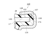
- the annular protrusion 146 may be provided at a corner (curved portion) on the outer periphery of the shoulder on the inner surface of the exterior can 116. More specifically, the annular protrusion 146 may be provided on the inner surface of the exterior can 116 inside a third point 157 that overlaps with the radial outer periphery of the sealing body 17 on the axial tip 148 side (upper side in the axial direction) on the inner surface of the exterior can 116. The annular protrusion 146 may also be provided on the outer side of a fourth point 158 that radially overlaps with an axially upper end face 152 of the periphery of the sealing body 17 on the inner surface of the exterior can 116.
- the annular protrusion 246 may be provided on the inner surface of the exterior can 216 inside a fourth point 158 that radially overlaps with the axially upper end face 152 of the peripheral portion of the sealing body 17.
- the annular protrusion 246 may also be provided on the inner surface of the exterior can 216 outside a first point 55 that radially overlaps with the axially lower end face 51 of the peripheral portion of the sealing body 17.
- annular protrusion 346 may be provided on the inner surface of the exterior can 316 inside a second location 356 that overlaps with the radial outer peripheral end 17a of the sealing body 17 on the axially lower side.
- annular protrusion 46, 346 on the inner surface of the outer can 16, 316 at a position close to the electrode body 14. This allows the electrolyte migration path between the outer can 16, 316 and the gasket 28 to be blocked on the electrode body 14 side. Furthermore, at corners, gaps are likely to occur between the gasket and the outer can. Therefore, by providing a protrusion 46, 146 at the corner as shown in Figures 3 and 6, the electrolyte migration path to the outside can be effectively blocked, and leakage, etc. can be effectively suppressed.
- the annular protrusion 46 is formed by spinning.
- the annular protrusion may be formed by any method, for example, by increasing the wall thickness at a specific axial position on the inner surface of the bottomed cylindrical outer can before processing, all around the circumference.
- a safety valve is provided at the upper end of the sealing body 17 at the upper end of the sealing body 17 .
- a cap including a protrusion that protrudes axially upward in the radial center of the upper end of the sealing body may also be provided.
- the sealing body 17 constitutes the positive electrode terminal and the outer can 16 constitutes the negative electrode terminal has been described.
- the sealing body may constitute the negative electrode terminal and the outer can constitute the positive electrode terminal.
Landscapes
- Chemical & Material Sciences (AREA)
- Chemical Kinetics & Catalysis (AREA)
- Electrochemistry (AREA)
- General Chemical & Material Sciences (AREA)
- Sealing Battery Cases Or Jackets (AREA)
Priority Applications (3)
| Application Number | Priority Date | Filing Date | Title |
|---|---|---|---|
| CN202380081003.XA CN120226195A (zh) | 2022-11-30 | 2023-11-17 | 圆筒形电池 |
| EP23897547.8A EP4629406A4 (en) | 2022-11-30 | 2023-11-17 | CYLINDRICAL BATTERY |
| JP2024561372A JPWO2024116896A1 (https=) | 2022-11-30 | 2023-11-17 |
Applications Claiming Priority (2)
| Application Number | Priority Date | Filing Date | Title |
|---|---|---|---|
| JP2022-191154 | 2022-11-30 | ||
| JP2022191154 | 2022-11-30 |
Publications (1)
| Publication Number | Publication Date |
|---|---|
| WO2024116896A1 true WO2024116896A1 (ja) | 2024-06-06 |
Family
ID=91323710
Family Applications (1)
| Application Number | Title | Priority Date | Filing Date |
|---|---|---|---|
| PCT/JP2023/041427 Ceased WO2024116896A1 (ja) | 2022-11-30 | 2023-11-17 | 円筒形電池 |
Country Status (4)
| Country | Link |
|---|---|
| EP (1) | EP4629406A4 (https=) |
| JP (1) | JPWO2024116896A1 (https=) |
| CN (1) | CN120226195A (https=) |
| WO (1) | WO2024116896A1 (https=) |
Citations (4)
| Publication number | Priority date | Publication date | Assignee | Title |
|---|---|---|---|---|
| JPH10199495A (ja) * | 1997-01-09 | 1998-07-31 | Mitsubishi Cable Ind Ltd | 密閉型電池の密閉構造およびそれに用いられるガスケット |
| WO2019194253A1 (ja) * | 2018-04-06 | 2019-10-10 | 三洋電機株式会社 | 電池 |
| JP2021150243A (ja) | 2020-03-23 | 2021-09-27 | Fdk株式会社 | 円筒形電池 |
| WO2022107716A1 (ja) * | 2020-11-19 | 2022-05-27 | 三洋電機株式会社 | 円筒形電池 |
Family Cites Families (3)
| Publication number | Priority date | Publication date | Assignee | Title |
|---|---|---|---|---|
| US3723184A (en) * | 1970-12-11 | 1973-03-27 | Gates Rubber Co | Compression cell closure |
| KR100739950B1 (ko) * | 2005-07-07 | 2007-07-16 | 삼성에스디아이 주식회사 | 원통형 이차전지 |
| JP5935013B2 (ja) * | 2012-02-24 | 2016-06-15 | パナソニックIpマネジメント株式会社 | 円筒形アルカリ蓄電池 |
-
2023
- 2023-11-17 CN CN202380081003.XA patent/CN120226195A/zh active Pending
- 2023-11-17 WO PCT/JP2023/041427 patent/WO2024116896A1/ja not_active Ceased
- 2023-11-17 JP JP2024561372A patent/JPWO2024116896A1/ja active Pending
- 2023-11-17 EP EP23897547.8A patent/EP4629406A4/en active Pending
Patent Citations (4)
| Publication number | Priority date | Publication date | Assignee | Title |
|---|---|---|---|---|
| JPH10199495A (ja) * | 1997-01-09 | 1998-07-31 | Mitsubishi Cable Ind Ltd | 密閉型電池の密閉構造およびそれに用いられるガスケット |
| WO2019194253A1 (ja) * | 2018-04-06 | 2019-10-10 | 三洋電機株式会社 | 電池 |
| JP2021150243A (ja) | 2020-03-23 | 2021-09-27 | Fdk株式会社 | 円筒形電池 |
| WO2022107716A1 (ja) * | 2020-11-19 | 2022-05-27 | 三洋電機株式会社 | 円筒形電池 |
Non-Patent Citations (1)
| Title |
|---|
| See also references of EP4629406A1 |
Also Published As
| Publication number | Publication date |
|---|---|
| EP4629406A4 (en) | 2025-12-17 |
| JPWO2024116896A1 (https=) | 2024-06-06 |
| CN120226195A (zh) | 2025-06-27 |
| EP4629406A1 (en) | 2025-10-08 |
Similar Documents
| Publication | Publication Date | Title |
|---|---|---|
| JP7799470B2 (ja) | 円筒形電池、及び円筒形電池の製造方法 | |
| EP4432433A1 (en) | Cylindrical battery | |
| JP7735444B2 (ja) | ガスケット、及び円筒形電池 | |
| US20240039096A1 (en) | Gasket and cylindrical battery | |
| US20240313305A1 (en) | Cylindrical battery | |
| JP7793532B2 (ja) | 円筒形電池 | |
| US20250210763A1 (en) | Cylindrical battery | |
| US20250273834A1 (en) | Cylindrical battery | |
| WO2024116896A1 (ja) | 円筒形電池 | |
| US20240039093A1 (en) | Hermetically sealed battery | |
| US20250210765A1 (en) | Cylindrical battery | |
| JP7818534B2 (ja) | 円筒形電池 | |
| US20260058328A1 (en) | Cylindrical battery | |
| EP4693639A1 (en) | Cylindrical battery | |
| WO2024116923A1 (ja) | 円筒形電池 | |
| WO2026070618A1 (ja) | 円筒形電池 | |
| WO2025182651A1 (ja) | 円筒形電池 | |
| WO2025248955A1 (ja) | 円筒形電池 | |
| WO2025164407A1 (ja) | 円筒形非水電解質二次電池 | |
| WO2025069750A1 (ja) | 円筒形電池 | |
| WO2026048538A1 (ja) | 円筒形電池 | |
| WO2024161974A1 (ja) | 円筒形電池 | |
| WO2025204681A1 (ja) | 円筒形電池 |
Legal Events
| Date | Code | Title | Description |
|---|---|---|---|
| 121 | Ep: the epo has been informed by wipo that ep was designated in this application |
Ref document number: 23897547 Country of ref document: EP Kind code of ref document: A1 |
|
| WWE | Wipo information: entry into national phase |
Ref document number: 2024561372 Country of ref document: JP |
|
| WWE | Wipo information: entry into national phase |
Ref document number: 202380081003.X Country of ref document: CN |
|
| WWP | Wipo information: published in national office |
Ref document number: 202380081003.X Country of ref document: CN |
|
| WWE | Wipo information: entry into national phase |
Ref document number: 2023897547 Country of ref document: EP |
|
| NENP | Non-entry into the national phase |
Ref country code: DE |
|
| ENP | Entry into the national phase |
Ref document number: 2023897547 Country of ref document: EP Effective date: 20250630 |
|
| WWP | Wipo information: published in national office |
Ref document number: 2023897547 Country of ref document: EP |