WO2024111596A1 - 作業機械、情報処理装置、プログラム - Google Patents
作業機械、情報処理装置、プログラム Download PDFInfo
- Publication number
- WO2024111596A1 WO2024111596A1 PCT/JP2023/041864 JP2023041864W WO2024111596A1 WO 2024111596 A1 WO2024111596 A1 WO 2024111596A1 JP 2023041864 W JP2023041864 W JP 2023041864W WO 2024111596 A1 WO2024111596 A1 WO 2024111596A1
- Authority
- WO
- WIPO (PCT)
- Prior art keywords
- work
- shovel
- unit
- work machine
- state
- Prior art date
- Legal status (The legal status is an assumption and is not a legal conclusion. Google has not performed a legal analysis and makes no representation as to the accuracy of the status listed.)
- Ceased
Links
Images




Classifications
-
- E—FIXED CONSTRUCTIONS
- E02—HYDRAULIC ENGINEERING; FOUNDATIONS; SOIL SHIFTING
- E02F—DREDGING; SOIL-SHIFTING
- E02F9/00—Component parts of dredgers or soil-shifting machines, not restricted to one of the kinds covered by groups E02F3/00 - E02F7/00
- E02F9/26—Indicating devices
- E02F9/261—Surveying the work-site to be treated
- E02F9/262—Surveying the work-site to be treated with follow-up actions to control the work tool, e.g. controller
-
- E—FIXED CONSTRUCTIONS
- E02—HYDRAULIC ENGINEERING; FOUNDATIONS; SOIL SHIFTING
- E02F—DREDGING; SOIL-SHIFTING
- E02F9/00—Component parts of dredgers or soil-shifting machines, not restricted to one of the kinds covered by groups E02F3/00 - E02F7/00
- E02F9/20—Drives; Control devices
-
- E—FIXED CONSTRUCTIONS
- E02—HYDRAULIC ENGINEERING; FOUNDATIONS; SOIL SHIFTING
- E02F—DREDGING; SOIL-SHIFTING
- E02F9/00—Component parts of dredgers or soil-shifting machines, not restricted to one of the kinds covered by groups E02F3/00 - E02F7/00
- E02F9/20—Drives; Control devices
- E02F9/2025—Particular purposes of control systems not otherwise provided for
- E02F9/205—Remotely operated machines, e.g. unmanned vehicles
-
- E—FIXED CONSTRUCTIONS
- E02—HYDRAULIC ENGINEERING; FOUNDATIONS; SOIL SHIFTING
- E02F—DREDGING; SOIL-SHIFTING
- E02F9/00—Component parts of dredgers or soil-shifting machines, not restricted to one of the kinds covered by groups E02F3/00 - E02F7/00
- E02F9/26—Indicating devices
-
- E—FIXED CONSTRUCTIONS
- E02—HYDRAULIC ENGINEERING; FOUNDATIONS; SOIL SHIFTING
- E02F—DREDGING; SOIL-SHIFTING
- E02F9/00—Component parts of dredgers or soil-shifting machines, not restricted to one of the kinds covered by groups E02F3/00 - E02F7/00
- E02F9/26—Indicating devices
- E02F9/261—Surveying the work-site to be treated
Definitions
- This disclosure relates to work machines, etc.
- the objective is to provide technology that enables a work machine to perform more appropriate operations.
- a motion planning unit that determines a future motion of the work machine from among a plurality of motions according to an execution status of the motion of the work machine; A work machine is provided.
- a motion planning unit that determines a future motion of the work machine from among a plurality of motions according to an execution status of the motion of the work machine; An information processing device is provided.
- the program is provided.
- Support equipment a motion planning step of determining a future motion of the work machine from among a plurality of motions according to an execution status of the motion of the work machine; a notification step of notifying an operator of the work machine of the operation determined by the operation planning step; The program is provided.
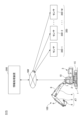
- FIG. 1 illustrates an example of a work support system.
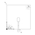
- FIG. 2 is a top view showing an example of a shovel.
- FIG. 2 is a diagram illustrating an example of a configuration for remote control of a shovel.
- FIG. 2 is a diagram illustrating an example of a hardware configuration of a shovel.
- FIG. 2 illustrates an example of a hardware configuration of an information processing device.
- FIG. 2 is a functional block diagram showing a first example of a functional configuration of the work support system.
- 11 is a diagram illustrating an example of a relationship between the timing of processing related to a motion plan for a shovel and the motion of a planned object.
- FIG. 1 illustrates an example of a work support system.
- FIG. 2 is a top view showing an example of a shovel.
- FIG. 2 is a diagram illustrating an example of a configuration for remote control of a shovel.
- FIG. 2 is a diagram illustrating an example of a hardware configuration of a shovel
- FIG. 13 is a diagram illustrating another example of the relationship between the timing of processing related to the operation plan of the shovel and the operation of the planned target.
- FIG. FIG. 11 is a state transition diagram showing an example of the transition of an operation of a shovel during slope construction work.
- FIG. 11 is a state transition diagram showing an example of the transition of the operation of a shovel during ground leveling work.
- FIG. 11 is a functional block diagram showing a second example of the functional configuration of the work support system.
- 10 is a flowchart illustrating an example of a process related to starting autonomous operation of a shovel.
- 1 is a main flowchart illustrating an example of a process related to a motion plan for a shovel and generation of a trajectory for a bucket.
- FIG. 2 is a diagram illustrating an example of an observation target area.
- 13 is a sub-flowchart illustrating an example of a process related to bucket trajectory generation.
- FIG. 13 is a diagram showing an example of cost conditions and operation parameters corresponding to a plurality of operation sections of an excavation operation of a shovel.
- 1 is a flowchart illustrating an example of a process related to operation control of a shovel.
- FIG. 1 An overview of an operation support system SYS according to this embodiment will be described with reference to FIGS. 1 to 3.
- FIG. 1 An overview of an operation support system SYS according to this embodiment will be described with reference to FIGS. 1 to 3.
- FIG. 1 An overview of an operation support system SYS according to this embodiment will be described with reference to FIGS. 1 to 3.
- FIG. 1 An overview of an operation support system SYS according to this embodiment will be described with reference to FIGS. 1 to 3.
- FIG. 1 is a diagram showing an example of an operation support system SYS.
- SYS operation support system
- FIG. 1 a left side view of the shovel 100 is shown.
- FIG. 2 is a top view showing an example of the shovel 100.
- FIG. 3 is a diagram showing an example of a configuration related to remote operation of the shovel 100.
- the direction in which the attachment AT extends when viewed from above the shovel 100 (the upward direction in FIG. 2) will be defined as "front,” and directions on the shovel 100 or directions seen from the shovel 100 may be described.
- the operation support system SYS includes an excavator 100, an information processing device 200, and a sensor group 300.
- the operation support system SYS uses the information processing device 200 to cooperate with the shovel 100 and provide support regarding the operation of the shovel 100.
- the operation support system SYS may include one or more excavators 100.
- the excavator 100 is a work machine that receives operation support in the operation support system SYS.
- the excavator 100 includes a lower running body 1, an upper rotating body 3, an attachment AT including a boom 4, an arm 5, and a bucket 6, and a cabin 10.
- the lower traveling body 1 uses crawlers 1C to travel the excavator 100.
- the crawlers 1C include a left crawler 1CL and a right crawler 1CR.
- the crawlers 1CL are hydraulically driven by a traveling hydraulic motor 1ML.
- the crawlers 1CL are hydraulically driven by a traveling hydraulic motor 1MR. This allows the lower traveling body 1 to travel on its own.
- the upper rotating body 3 is mounted on the lower running body 1 so as to be rotatable (freely rotatable) via the rotating mechanism 2.
- the upper rotating body 3 rotates relative to the lower running body 1 when the rotating mechanism 2 is hydraulically driven by a rotating hydraulic motor 2M.
- the boom 4 is attached to the front center of the upper rotating body 3 so that it can be raised and lowered around a rotation axis that runs along the left-right direction.
- the arm 5 is attached to the tip of the boom 4 so that it can rotate around a rotation axis that runs along the left-right direction.
- the bucket 6 is attached to the tip of the arm 5 so that it can rotate around a rotation axis that runs along the left-right direction.
- the bucket 6 is an example of an end attachment and is used, for example, for excavation work, slope work, and ground leveling work.
- the bucket 6 is attached to the tip of the arm 5 in a manner that allows it to be appropriately replaced depending on the work content of the shovel 100.
- a bucket of a different type from the bucket 6, such as a relatively large bucket, a bucket for slopes, a dredging bucket, etc. may be attached to the tip of the arm 5.
- an end attachment of a type other than a bucket, such as an agitator, breaker, crusher, etc. may be attached to the tip of the arm 5.
- a spare attachment such as a quick coupling or tilt rotator may be provided between the arm 5 and the end attachment.
- the boom 4, arm 5, and bucket 6 are hydraulically driven by a boom cylinder 7, arm cylinder 8, and bucket cylinder 9, respectively.
- the cabin 10 is a control room where an operator sits and operates the excavator 100.
- the cabin 10 is mounted, for example, on the front left side of the upper rotating body 3.
- the excavator 100 is equipped with a communication device 60 and can communicate with the information processing device 200 via a specified communication line NW.
- the communication line NW may include, for example, a local network (LAN: Local Area Network) at a work site.
- the communication line NW may also include a wide area network (WAN: Wide Area Network).
- Wide area networks include, for example, mobile communication networks ending in base stations, satellite communication networks using communication satellites, and Internet networks.
- the communication line NW may also include, for example, short-distance communication lines based on wireless communication standards such as Wi-Fi and Bluetooth (registered trademark).
- the excavator 100 operates driven elements such as the lower traveling body 1 (i.e., a pair of left and right crawlers 1CL, 1CR), upper rotating body 3, boom 4, arm 5, and bucket 6 in response to the operation of an operator in the cabin 10.
- the lower traveling body 1 i.e., a pair of left and right crawlers 1CL, 1CR
- upper rotating body 3 i.e., a pair of left and right crawlers 1CL, 1CR
- boom 4, arm 5, and bucket 6 in response to the operation of an operator in the cabin 10.
- the shovel 100 may be configured to be remotely operable from outside the shovel 100.
- the interior of the cabin 10 may be unmanned.
- the shovel 100 is dedicated to remote operation, the cabin 10 may be omitted.
- the operation of the operator includes at least one of the operation of the operating device 26 by the operator inside the cabin 10 and the remote operation by an external operator.
- remote operation includes a mode in which the shovel 100 is operated by operation input related to the actuator of the shovel 100 performed by a remote operation support device 400 capable of communicating with the shovel 100 via a communication line NW.
- the remote operation support device 400 may be provided separately from the information processing device 200, or may be the information processing device 200.
- the remote operation support device 400 is provided, for example, in a management center that manages the work of the shovel 100 from the outside.
- the remote operation support device 400 may also be a portable operation terminal, in which case the operator can remotely operate the shovel 100 while directly checking the work status of the shovel 100 from the vicinity of the shovel 100.
- the shovel 100 may transmit, for example, through the communication device 60 described below, an image (hereinafter, "peripheral image") showing the surroundings including the front of the shovel 100 based on an image output by an imaging device mounted on the shovel 100 to the remote operation support device 400.
- the shovel 100 may also transmit the image output by the imaging device to the remote operation support device 400 through the communication device 60, and the remote operation support device 400 may process the image received from the shovel 100 to generate a peripheral image.
- the remote operation support device 400 may then display the peripheral image showing the surroundings including the front of the shovel 100 on its own display device.
- Various information images (information screens) displayed on the output device 50 (display device) inside the cabin 10 of the shovel 100 may also be displayed on the display device of the remote operation support device 400.
- the excavator 100 may operate actuators and drive driven elements such as the lower traveling body 1, the upper rotating body 3, the boom 4, the arm 5, and the bucket 6 in response to a remote operation signal indicating the content of the remote operation received from the remote operation support device 400 by the communication device 60.
- Remote control may also include a mode in which the shovel 100 is operated by external voice input or gesture input to the shovel 100 by a person (e.g., a worker) around the shovel 100.
- the shovel 100 recognizes voices uttered by surrounding workers and gestures made by workers through a voice input device (e.g., a microphone) or a gesture input device (e.g., an imaging device) mounted on the shovel 100.
- the shovel 100 may then operate actuators according to the content of the recognized voices and gestures to drive driven elements such as the lower traveling body 1 (left and right crawlers 1C), upper rotating body 3, boom 4, arm 5, and bucket 6.
- the excavator 100 may also automatically operate the actuators regardless of the content of the operator's operation. This allows the excavator 100 to realize a function for automatically operating at least some of the driven elements such as the lower traveling body 1, the upper rotating body 3, and the attachment AT, i.e., a so-called “automatic driving function” or “machine control (MC) function.”
- the automatic driving function includes, for example, a semi-automatic driving function (operation assistance type MC function).
- the semi-automatic driving function is a function that automatically operates a driven element (actuator) other than the driven element (actuator) to be operated in response to the operation of the operator.
- the automatic driving function may also include a fully automatic driving function (fully automatic MC function).
- the fully automatic driving function is a function that automatically operates at least a part of a plurality of driven elements (hydraulic actuators) on the assumption that there is no operation from the operator.
- the fully automatic driving function is enabled in the shovel 100, the inside of the cabin 10 may be unmanned. Furthermore, when the shovel 100 is dedicated to fully automatic operation, the cabin 10 may be omitted.
- the semi-automatic driving function and the fully automatic driving function include, for example, a rule-based automatic driving function.
- the rule-based automatic driving function is an automatic driving function in which the operation content of the driven element (actuator) to be the target of automatic operation is automatically determined according to a rule that is specified in advance.
- the semi-automatic driving function and the fully automatic driving function may include an autonomous driving function.
- the autonomous driving function is a function in which the excavator 100 autonomously makes various decisions and determines the operation of the driven element (hydraulic actuator) that is the target of the autonomous driving based on the results of those decisions.
- the work of the shovel 100 may also be remotely monitored.
- a remote monitoring support device having the same functions as the remote operation support device 400 may be provided.
- the remote monitoring support device is, for example, the information processing device 200. This allows a monitor, who is a user of the remote monitoring support device, to monitor the status of the work of the shovel 100 while checking the surrounding images displayed on the display device of the remote monitoring support device. Also, for example, if the monitor determines it is necessary from the perspective of safety, he or she can use the input device of the remote monitoring support device to make a specified input, thereby intervening in the operation by the operator of the shovel 100 or automatic operation and bringing the shovel 100 to an emergency stop.
- the information processing device 200 communicates with the shovel 100 to cooperate with it and provide support for the operation of the shovel 100.
- the information processing device 200 is, for example, a server device or a management terminal device installed in a management office in the work site of the shovel 100, or in a management center that manages the operating status of the shovel 100 and is located in a place different from the work site of the shovel 100.
- the server device may be an on-premise server, a cloud server, or an edge server.
- the management terminal device may be, for example, a stationary terminal device such as a desktop PC (Personal Computer), or a portable terminal device (mobile terminal) such as a tablet terminal, a smartphone, or a laptop PC.
- a worker at the work site, a supervisor who supervises the work, or a manager who manages the work site can move around the work site carrying the portable information processing device 200.
- an operator can, for example, bring the portable information processing device 200 into the cabin of the shovel 100.
- the information processing device 200 acquires data on the operating state from the shovel 100. This enables the information processing device 200 to grasp the operating state of the shovel 100 and monitor the presence or absence of abnormalities in the shovel 100.
- the information processing device 200 can also display data on the operating state of the shovel 100 via, for example, a display device 208 described below, for a user to confirm.
- the information processing device 200 can also, for example, train a learning model to learn the operating state of the shovel 100, and generate a trained model for supporting the operation of the shovel 100.
- the information processing device 200 may also transmit to the shovel 100 various data such as programs and reference data used in the processing of the controller 30, etc., to the shovel 100. This allows the shovel 100 to perform various processes related to the operation of the shovel 100 using the various data downloaded from the information processing device 200.
- the sensor group 300 is installed at the work site of the shovel 100.
- the work target is, for example, soil and sand in the work area around the shovel 100.
- the operation support system SYS includes multiple shovels 100
- a sensor group 300 is provided for each shovel 100.
- multiple shovels 100 included in the operation support system SYS work at the same work site, one sensor group 300 may be shared by the multiple shovels 100.
- Sensor group 300 includes sensors 300-1 to 300-M (M: an integer of 2 or more). Sensors 300-1 to 300-M measure the state of objects at the work site around shovel 100 and acquire measurement data relating to the state. Objects at the work site include the work target around shovel 100 (soil and sand in the work area), as well as other shovels around shovel 100, work machines such as bulldozers, and work vehicles such as trucks for transporting soil and sand.
- the state of an object includes the shape and characteristics of the object.
- the sensors 300-1 to 300-M include, for example, a distance measurement sensor (distance sensor).
- Distance measurement sensors include, for example, LIDAR (Light Detecting and Ranging), millimeter wave radar, ultrasonic sensors, infrared sensors, etc.
- the sensors 300-1 to 300-M may also include, for example, a stereo camera, a TOF (Time Of Flight) camera, or other 3D cameras capable of acquiring data related to distance (depth) in addition to two-dimensional images.
- the sensors 300-1 to 300-M may also include a mixture of distance measurement sensors and 3D cameras. This allows the sensor group 300 to acquire measurement data representing the shape of objects at the work site around the shovel 100.
- sensors capable of acquiring measurement data representing the shape of objects such as distance measurement sensors and 3D cameras, may be referred to as "shape sensors" for convenience.
- the sensors 300-1 to 300-M may also include a multi-wavelength spectroscopic camera.
- Multi-wavelength spectroscopic cameras include, for example, multispectral cameras and hyperspectral cameras. This allows the sensor group 300 to acquire measurement data that represents the characteristics of objects at the work site around the shovel 100, such as the hardness and moisture content of soil and sand.
- characteristics sensors may be referred to as "characteristic sensors.”
- sensors 300-1 to 300-M include multiple shape sensors.
- the multiple shape sensors may be provided in different locations on the work site around the shovel 100, and such that the sensing range of each sensor overlaps with the sensing range of at least one other shape sensor.
- the other shape sensors may be able to obtain measurement data representing the shape of the object in that range. Therefore, the sensor group 300 can more reliably obtain measurement data representing the shape of objects in the work site around the shovel 100.
- the sensors 300-1 to 300-M may include multiple characteristic sensors.
- the multiple characteristic sensors may be provided in different locations in the work site around the shovel 100, and so that the sensing range of each sensor overlaps with at least one other characteristic sensor.
- the other shape sensors may be able to obtain measurement data representing the characteristics of the object in that range. Therefore, the sensor group 300 can more reliably obtain measurement data representing the characteristics of objects in the work site around the shovel 100.
- sensors 300-1 to 300-M may include a sensor having both the functions of a shape sensor and a characteristic sensor (hereinafter, "integrated sensor”).
- sensors 300-1 to 300-M may include multiple integrated sensors.
- the multiple characteristic sensors may be provided at different locations in the work site around shovel 100, and each of the sensing ranges may overlap with at least one other characteristic sensor.
- the sensor group 300 may simply include only one shape sensor or one characteristic sensor.
- the operation support system SYS may simply include only one sensor capable of acquiring measurement data regarding the state of objects at the work site around the shovel 100.
- Sensors 300-1 to 300-M may be fixed to the work site around shovel 100, or may be mounted on a mobile object capable of moving within the work site around shovel 100.
- Mobile objects include, for example, work machines and work vehicles that move within the work site.
- Mobile objects that can move within the work site may also include, for example, flying objects such as drones that fly above the work site.
- the output (measurement data) of the sensors 300-1 to 300-M is taken into the information processing device 200 through the communication line NW.
- the output of the sensors 300-1 to 300-M is taken into the information processing device 200 directly through the communication line NW, for example.
- the output of the sensors 300-1 to 300-M may also be taken into the shovel 100 once through the communication line NW, and then taken into the information processing device 200 via the shovel 100. If the sensors 300-1 to 300-M are mounted on a specific device, such as the above-mentioned mobile object, the output of the sensors 300-1 to 300-M may also be taken into the specific device once, and then taken into the information processing device 200 from that device.
- the hardware configuration of the remote operation support device 400 may be the same as that of the information processing device 200. Therefore, illustrations and descriptions of the hardware configuration of the remote operation support device 400 will be omitted.
- FIG. 4 is a block diagram showing an example of a hardware configuration of the shovel 100.
- the excavator 100 includes various components, such as a hydraulic drive system for hydraulically driving the driven elements, an operation system for operating the driven elements, a user interface system for exchanging information with the user, a communication system for communicating with the outside world, and a control system for various controls.
- the hydraulic drive system of the excavator 100 includes hydraulic actuators HA that hydraulically drive each of the driven elements, such as the lower traveling structure 1 (left and right crawlers 1C), upper rotating structure 3, boom 4, arm 5, and bucket 6, as described above.
- the hydraulic drive system of the excavator 100 according to this embodiment also includes an engine 11, a regulator 13, a main pump 14, and a control valve 17.
- the hydraulic actuator HA includes travel hydraulic motors 1ML, 1MR, swing hydraulic motor 2M, boom cylinder 7, arm cylinder 8, and bucket cylinder 9.
- the shovel 100 a part or all of the hydraulic actuator HA may be replaced with an electric actuator.
- the shovel 100 may be a hybrid shovel or an electric shovel.
- the engine 11 is the prime mover of the excavator 100 and the main power source in the hydraulic drive system.
- the engine 11 is, for example, a diesel engine that uses light oil as fuel.
- the engine 11 is mounted, for example, at the rear of the upper rotating body 3.
- the engine 11 rotates at a constant speed at a preset target speed under direct or indirect control by the controller 30 (described later), for example, and drives the main pump 14 and the pilot pump 15.
- prime movers e.g., electric motors
- the excavator 100 instead of or in addition to the engine 11.
- the regulator 13 controls (adjusts) the discharge volume of the main pump 14 under the control of the controller 30. For example, the regulator 13 adjusts the angle of the swash plate of the main pump 14 (hereinafter, the "tilt angle") in response to a control command from the controller 30.
- the main pump 14 supplies hydraulic oil to the control valve 17 through a high-pressure hydraulic line.
- the main pump 14 is mounted, for example, at the rear of the upper rotating body 3, similar to the engine 11. As described above, the main pump 14 is driven by the engine 11.
- the main pump 14 is, for example, a variable displacement hydraulic pump, and as described above, under the control of the controller 30, the tilt angle of the swash plate is adjusted by the regulator 13 to adjust the stroke length of the piston, thereby controlling the discharge flow rate and discharge pressure.
- the control valve 17 drives the hydraulic actuators HA in response to the operator's operation of the operating device 26, the contents of remote operation, or operation commands corresponding to the automatic operation function.
- the control valve 17 is mounted, for example, in the center of the upper rotating body 3.
- the control valve 17 is connected to the main pump 14 via a high-pressure hydraulic line, and selectively supplies hydraulic oil supplied from the main pump 14 to each hydraulic actuator in response to the operator's operation or operation commands corresponding to the automatic operation function.
- the control valve 17 includes multiple control valves (directional control valves) that control the flow rate and flow direction of the hydraulic oil supplied from the main pump 14 to each hydraulic actuator HA.
- the operating system of the excavator 100 includes a pilot pump 15 , an operating device 26 , a hydraulic control valve 31 , a shuttle valve 32 , and a hydraulic control valve 33 .
- the pilot pump 15 supplies pilot pressure to various hydraulic equipment via a pilot line 25.
- the pilot pump 15 is mounted, for example, at the rear of the upper rotating body 3, similar to the engine 11.
- the pilot pump 15 is, for example, a fixed displacement hydraulic pump, and is driven by the engine 11 as described above.
- the pilot pump 15 may be omitted.
- the relatively high pressure hydraulic oil discharged from the main pump 14 is reduced in pressure by a specified pressure reducing valve, and the relatively low pressure hydraulic oil is supplied to various hydraulic equipment as pilot pressure.
- the operating device 26 is provided near the cockpit of the cabin 10, and is used by the operator to operate the various driven elements. Specifically, the operating device 26 is used by the operator to operate the hydraulic actuators HA that drive the respective driven elements, and as a result, the operator can operate the driven elements that are the targets of the drive of the hydraulic actuators HA.
- the operating device 26 includes pedal devices and lever devices for operating the respective driven elements (hydraulic actuators HA).
- the operating device 26 is of a hydraulic pilot type. Specifically, the operating device 26 uses hydraulic oil supplied from the pilot pump 15 through the pilot line 25 and the pilot line 25A branching therefrom, and outputs pilot pressure corresponding to the operation to the secondary pilot line 27A.
- the pilot line 27A is connected to one inlet port of the shuttle valve 32, and is connected to the control valve 17 via the pilot line 27 connected to the outlet port of the shuttle valve 32.
- pilot pressure corresponding to the operation of various driven elements (hydraulic actuators HA) in the operating device 26 can be input to the control valve 17 via the shuttle valve 32. Therefore, the control valve 17 can drive each hydraulic actuator HA according to the operation of the operating device 26 by an operator or the like.
- the operating device 26 may also be electric.
- the pilot line 27A, shuttle valve 32, and hydraulic control valve 33 are omitted.
- the operating device 26 outputs an electric signal (hereinafter, "operation signal") according to the operation content, and the operation signal is input to the controller 30.
- the controller 30 then outputs a control command according to the content of the operation signal, that is, a control signal according to the operation content for the operating device 26, to the hydraulic control valve 31.
- a pilot pressure according to the operation content of the operating device 26 is input from the hydraulic control valve 31 to the control valve 17, and the control valve 17 can drive each hydraulic actuator HA according to the operation content of the operating device 26.
- control valves built into the control valve 17 that drive the respective hydraulic actuators HA may be of the electromagnetic solenoid type.
- the operation signal output from the operating device 26 may be directly input to the control valve 17 (i.e., to the electromagnetic solenoid type control valve).
- part or all of the hydraulic actuator HA may be replaced with an electric actuator.
- the controller 30 may output a control command corresponding to the operation content of the operating device 26 or the remote operation content specified by the remote operation signal to the electric actuator or a driver that drives the electric actuator.
- the operating device 26 may be omitted.
- the hydraulic control valve 31 is provided for each driven element (hydraulic actuator HA) to be operated by the operating device 26 and for each driving direction of the driven element (hydraulic actuator HA) (e.g., the raising direction and lowering direction of the boom 4).
- the hydraulic control valve 31 may be provided, for example, in the pilot line 25B between the pilot pump 15 and the control valve 17, and may be configured to change its flow area (i.e., the cross-sectional area through which the hydraulic oil can flow).
- the hydraulic control valve 31 can indirectly apply a predetermined pilot pressure corresponding to a control signal from the controller 30 to the control valve 17 through the shuttle valve 32 between the pilot line 27B and the pilot line 27. Therefore, for example, the controller 30 can supply pilot pressure from the hydraulic control valve 31 to the control valve 17 in response to an operation command corresponding to the automatic driving function, thereby realizing the operation of the excavator 100 using the automatic driving function.
- the controller 30 may also control the hydraulic control valve 31 to realize remote operation of the excavator 100. Specifically, the controller 30 outputs a control signal corresponding to the content of the remote operation specified by the remote operation signal received from the remote operation support device 400 to the hydraulic control valve 31 via the communication device 60. As a result, the controller 30 can supply pilot pressure corresponding to the content of the remote operation from the hydraulic control valve 31 to the control valve 17, thereby realizing the operation of the excavator 100 based on the remote operation by the operator.
- the controller 30 can supply pilot pressure corresponding to the operation content (operation signal) of the operating device 26 directly to the control valve 17 from the hydraulic control valve 31, thereby realizing the operation of the excavator 100 based on the operation of the operator.
- the shuttle valve 32 has two inlet ports and one outlet port, and outputs hydraulic oil having the higher pilot pressure of the two pilot pressures input to the inlet ports to the outlet port.
- the shuttle valve 32 is provided for each driven element (hydraulic actuator HA) to be operated by the operating device 26 and for each driving direction of the driven element (hydraulic actuator HA) in the same manner as the hydraulic control valve 31.
- two shuttle valves 32 are provided for each double-acting hydraulic actuator HA for driving the lower traveling body 1, upper rotating body 3, boom 4, arm 5, bucket 6, etc.
- One of the two inlet ports of the shuttle valve 32 is connected to the secondary pilot line 27A of the operating device 26 (specifically, the above-mentioned lever device and pedal device included in the operating device 26), and the other is connected to the secondary pilot line 27B of the hydraulic control valve 31.
- the outlet port of the shuttle valve 32 is connected to the pilot port of the corresponding control valve of the control valve 17 through the pilot line 27.
- the corresponding control valve is a control valve that drives the hydraulic actuator HA that is the operation target of the above-mentioned lever device or pedal device connected to one inlet port of the shuttle valve 32.
- each of these shuttle valves 32 can apply the higher of the pilot pressure of the pilot line 27A on the secondary side of the operating device 26 and the pilot pressure of the pilot line 27B on the secondary side of the hydraulic control valve 31 to the pilot port of the corresponding control valve.
- the controller 30 can control the corresponding control valve regardless of the operator's operation of the operating device 26 by outputting a pilot pressure higher than the pilot pressure on the secondary side of the operating device 26 from the hydraulic control valve 31. Therefore, the controller 30 can control the operation of the driven elements (lower traveling body 1, upper rotating body 3, boom 4, arm 5, bucket 6) regardless of the operating state of the operating device 26 by the operator, thereby realizing an automatic driving function or a remote operation function.
- the hydraulic control valve 33 is provided in the pilot line 27A that connects the operating device 26 and the shuttle valve 32.
- the hydraulic control valve 33 is configured to be able to change its flow area, for example.
- the hydraulic control valve 33 operates in response to a control signal input from the controller 30.
- the controller 30 can forcibly reduce the pilot pressure output from the operating device 26 when the operating device 26 is being operated by the operator. Therefore, even when the operating device 26 is being operated, the controller 30 can forcibly suppress or stop the operation of the hydraulic actuator HA corresponding to the operation of the operating device 26.
- the controller 30 can reduce the pilot pressure output from the operating device 26 to make it lower than the pilot pressure output from the hydraulic control valve 31.
- the controller 30 can reliably apply a desired pilot pressure to the pilot port of the control valve in the control valve 17, for example, regardless of the operation content of the operating device 26. Therefore, for example, the controller 30 can more appropriately realize the automatic operation function and remote control function of the excavator 100 by controlling the hydraulic control valve 33 in addition to the hydraulic control valve 31.
- the user interface system of the shovel 100 includes an operation device 26 , an output device 50 , and an input device 52 .
- the output device 50 outputs various information to a user of the excavator 100 (e.g., an operator of the cabin 10 or an external remote control operator) and people in the vicinity of the excavator 100 (e.g., a worker or a driver of a work vehicle).
- a user of the excavator 100 e.g., an operator of the cabin 10 or an external remote control operator
- people in the vicinity of the excavator 100 e.g., a worker or a driver of a work vehicle.
- the output device 50 includes lighting equipment and display devices that output various information in a visual manner.
- Lighting equipment is, for example, a warning light (indicator lamp), etc.
- Display devices are, for example, a liquid crystal display and an organic EL (Electroluminescence) display, etc.
- the lighting equipment and display devices may be provided inside the cabin 10 and output various information in a visual manner to an operator, etc. inside the cabin 10.
- the lighting equipment and display devices may be provided, for example, on the side of the upper rotating body 3 and output various information in a visual manner to workers, etc. around the excavator 100.
- the output device 50 may also include a sound output device that outputs various information by auditory means (see FIG. 7). Sound output devices include, for example, buzzers and speakers.
- the sound output device may be provided, for example, at least one of the inside and outside of the cabin 10, and may output various information by auditory means to an operator inside the cabin 10 or to people (workers, etc.) around the excavator 100.
- the output device 50 may also include a device that outputs various information in a tactile manner, such as by vibration of the cockpit.
- the input device 52 receives various inputs from the user of the excavator 100, and signals corresponding to the received inputs are input to the controller 30.
- the input device 52 is provided inside the cabin 10 and receives inputs from an operator or the like inside the cabin 10.
- the input device 52 may also be provided, for example, on the side of the upper rotating body 3 and receives inputs from workers or the like in the vicinity of the excavator 100.
- the input device 52 includes an operation input device that accepts input from a user through mechanical operation.
- the operation input device may include a touch panel mounted on the display device, a touch pad installed around the display device, a button switch, a lever, a toggle, a knob switch provided on the operation device 26 (lever device), etc.
- the input device 52 may also include an audio input device that accepts audio input from the user.
- the audio input device may include, for example, a microphone.
- the input device 52 may also include a gesture input device that accepts gesture input from the user.
- the gesture input device includes, for example, an imaging device that captures an image of a gesture made by the user.
- the input device 52 may also include a biometric input device that accepts biometric input from the user.
- the biometric input includes, for example, input of biometric information such as the user's fingerprint or iris.
- the communication system of the shovel 100 includes a communication device 60 .
- the communication device 60 connects to an external communication line NW and communicates with a device provided separately from the shovel 100.
- the device provided separately from the shovel 100 may include a device outside the shovel 100, as well as a portable terminal device (mobile terminal) brought into the cabin 10 by the user of the shovel 100.
- the communication device 60 may include, for example, a mobile communication module conforming to standards such as 4G ( 4th Generation) and 5G ( 5th Generation).
- the communication device 60 may also include, for example, a satellite communication module.
- the communication device 60 may also include, for example, a WiFi communication module or a Bluetooth (registered trademark) communication module.
- the communication device 60 may include multiple communication devices according to the types of the communication lines NW.
- the communication device 60 communicates with external devices such as the information processing device 200 and the remote operation support device 400 at the work site through a local communication line established at the work site.
- the local communication line is, for example, a local 5G (so-called local 5G) mobile communication line established at the work site or a local network using Wi-Fi 6.
- the communication device 60 may also communicate with an information processing device 200 or a remote operation support device 400 outside the work site via a wide area communication line that includes the work site, i.e., a wide area network.
- control system of the shovel 100 includes a controller 30.
- the control system of the shovel 100 according to this embodiment also includes an operating pressure sensor 29, a sensor 40, and sensors S1 to S9.
- the controller 30 performs various controls related to the excavator 100.
- the controller 30 may be realized by any hardware or any combination of hardware and software.
- the controller 30 includes an auxiliary storage device 30A, a memory device 30B, a CPU (Central Processing Unit) 30C, and an interface device 30D, which are connected by a bus BS1.
- auxiliary storage device 30A a memory device 30B
- CPU Central Processing Unit
- interface device 30D an interface device 30D
- the auxiliary storage device 30A is a non-volatile storage means that stores the programs to be installed as well as necessary files, data, etc.
- the auxiliary storage device 30A is, for example, an EEPROM (Electrically Erasable Programmable Read-Only Memory) or flash memory.
- the memory device 30B loads the program from the auxiliary storage device 30A so that the program can be read by the CPU 30C.
- the memory device 30B is, for example, a static random access memory (SRAM).
- the CPU 30C for example, executes a program loaded into the memory device 30B and realizes various functions of the controller 30 according to the program's instructions.
- the interface device 30D functions, for example, as a communication interface for connecting to a communication line inside the excavator 100.
- the interface device 30D may include multiple different types of communication interfaces according to the type of communication line to be connected.
- the interface device 30D also functions as an external interface for reading data from a recording medium and writing data to the recording medium.
- the recording medium is, for example, a dedicated tool connected to a connector installed inside the cabin 10 via a detachable cable.
- the recording medium may also be a general-purpose recording medium, such as an SD memory card or a USB (Universal Serial Bus) memory.
- a program that realizes various functions of the controller 30 can be provided, for example, by a portable recording medium and installed in the auxiliary storage device 30A of the controller 30.
- the program may also be downloaded from another computer (for example, the information processing device 200) outside the excavator 100 via the communication device 60 and installed in the auxiliary storage device 30A.
- controller 30 may be realized by another controller (control device). In other words, the functions of the controller 30 may be realized in a distributed manner by multiple controllers mounted on the excavator 100.
- the operating pressure sensor 29 detects the pilot pressure on the secondary side (pilot line 27A) of the hydraulic pilot type operating device 26, i.e., the pilot pressure corresponding to the operating state of each driven element (hydraulic actuator) in the operating device 26.
- the detection signal of the pilot pressure by the operating pressure sensor 29 corresponding to the operating state of each driven element (hydraulic actuator HA) in the operating device 26 is taken into the controller 30.
- the operating pressure sensor 29 is omitted. This is because the controller 30 can grasp the operating state of each driven element through the operating device 26 based on the operating signal received from the operating device 26.
- the sensor 40 acquires measurement data, for example, regarding the shape of objects around the shovel 100.
- the senor 40 is a shape sensor, such as a distance sensor or a 3D camera, capable of acquiring measurement data representing the shape of objects around the shovel 100.
- the sensor 40 may be an integrated sensor that has the function of a characteristic sensor, such as a multi-wavelength spectroscopic camera, capable of acquiring measurement data representing the characteristics of objects around the shovel 100, in addition to the function of a shape sensor.
- the sensor 40 includes sensors 40F, 40B, 40L, and 40R.
- Sensor 40F measures the state (shape and characteristics) of an object in front of the upper rotating body 3.
- Sensor 40B measures the state of an object on the upper rotating body 3.
- Sensor 40L measures the state of an object to the left of the upper rotating body 3.
- Sensor 40R measures the state of an object to the right of the upper rotating body 3. In this way, the sensor 40 can measure the state of objects in a range around the shovel 100, that is, an angular direction of 360 degrees, when viewed from above the shovel 100.
- the sensors 40F, 40B, 40L, and 40R may be collectively or individually referred to as "sensor 40X.”
- the output data of the sensor 40 (sensor 40X) (i.e., measurement data relating to the state of objects around the shovel 100) is input to the controller 30 via a one-to-one communication line or an on-board network. This allows the controller 30 to grasp, for example, the shape, characteristics, and other state of objects around the shovel 100 based on the output data of the sensor 40X.
- sensors 40B, 40L, and 40R may be omitted.
- the sensor S1 is attached to the boom 4 and measures the attitude of the boom 4.
- the sensor S1 outputs measurement data representing the attitude of the boom 4.
- the attitude of the boom 4 is, for example, the attitude angle around the rotation axis of the base end corresponding to the connection part of the boom 4 with the upper rotating body 3 (hereinafter, "boom angle").
- the sensor S1 includes, for example, a rotary potentiometer, a rotary encoder, an acceleration sensor, an angular acceleration sensor, a six-axis sensor, an IMU (Inertial Measurement Unit), etc. The same may be true for the sensors S2 to S4 below.
- the sensor S1 may also include a cylinder sensor that detects the extension/retraction position of the boom cylinder 7. The same may be true for the sensors S2 and S3 below.
- the output of the sensor S1 (measurement data representing the attitude of the boom 4) is taken into the controller 30. This allows the controller 30 to grasp the attitude of the boom 4.
- Sensor S2 is attached to arm 5 and measures the posture of arm 5.
- Sensor S2 outputs measurement data representing the posture of arm 5.
- the posture of arm 5 is, for example, the posture angle around the rotation axis of the base end corresponding to the connection part of arm 5 with boom 4 (hereinafter referred to as "arm angle").
- the output of sensor S2 (measurement data representing the posture of arm 5) is input to controller 30. This allows controller 30 to grasp the posture of arm 5.
- Sensor S3 is attached to bucket 6 and measures the attitude of bucket 6.
- Sensor S3 outputs measurement data that indicates the attitude of bucket 6.
- the attitude of bucket 6 is, for example, the attitude angle around the rotation axis of the base end that corresponds to the connection part of bucket 6 with arm 5 (hereinafter, "arm angle").
- the output of sensor S3 (measurement data that indicates the attitude of bucket 6) is input to controller 30. This allows controller 30 to grasp the attitude of bucket 6.
- the sensor S4 measures the attitude of the shovel 100's body (e.g., the upper rotating body 3).
- the sensor S4 outputs measurement data representing the attitude of the shovel 100's body.
- the attitude of the shovel 100's body is, for example, the inclination of the body relative to a predetermined reference plane (e.g., a horizontal plane).
- the sensor S4 is attached to the upper rotating body 3 and measures the inclination angles of the shovel 100 about two axes in the front-rear and left-right directions (hereinafter, "front-rear inclination angle" and "left-right inclination angle”).
- the output of the sensor S4 (measurement data representing the attitude of the shovel 100's body) is input to the controller 30. This allows the controller 30 to grasp the attitude (inclination) of the body (upper rotating body 3).
- Sensor S5 is attached to the upper rotating body 3 and measures the rotation state of the upper rotating body 3.
- Sensor S5 outputs measurement data representing the rotation state of the upper rotating body 3.
- Sensor S5 measures, for example, the rotation angular velocity and rotation angle of the upper rotating body 3.
- Sensor S5 includes, for example, a gyro sensor, a resolver, a rotary encoder, etc.
- the output of sensor S5 (measurement data representing the rotation state of the upper rotating body 3) is input to controller 30. This allows controller 30 to grasp the rotation state of the upper rotating body 3, such as the rotation angle.
- the controller 30 can grasp (estimate) the position of the tip of the attachment AT (bucket 6) based on the outputs of the sensors S1 to S5.
- sensor S4 includes a gyro sensor, a six-axis sensor, an IMU, or the like capable of detecting angular velocity around three axes
- the rotation state e.g., rotation angular velocity
- sensor S5 may be omitted.
- the sensor S6 measures the position of the excavator 100.
- the sensor S6 may measure the position in world (global) coordinates, or in local coordinates at the work site.
- the sensor S6 is, for example, a GNSS (Global Navigation Satellite System) sensor.
- the sensor S6 is a transceiver that communicates with equipment that serves as a reference for the work site position and is capable of outputting a signal corresponding to the position relative to the reference.
- the output of the sensor S6 is taken into the controller 30.
- Sensor S7 measures the pressure (cylinder pressure) in the oil chamber of boom cylinder 7.
- Sensor S7 includes, for example, a sensor that measures the cylinder pressure (rod pressure) in the oil chamber on the rod side of boom cylinder 7, and a sensor that measures the cylinder pressure (bottom pressure) in the oil chamber on the bottom side.
- the output of sensor S7 (measurement data of the cylinder pressure of boom cylinder 7) is taken into controller 30.
- Sensor S8 measures the pressure (cylinder pressure) in the oil chamber of arm cylinder 8.
- Sensor S8 includes, for example, a sensor that measures the cylinder pressure (rod pressure) in the oil chamber on the rod side of arm cylinder 8, and a sensor that measures the cylinder pressure (bottom pressure) in the oil chamber on the bottom side of arm cylinder 8.
- the output of sensor S8 (measurement data of the cylinder pressure of arm cylinder 8) is taken into controller 30.
- Sensor S9 measures the pressure (cylinder pressure) in the oil chamber of bucket cylinder 9.
- Sensor S9 includes, for example, a sensor that measures the cylinder pressure (rod pressure) in the oil chamber on the rod side of bucket cylinder 9, and a sensor that measures the cylinder pressure (bottom pressure) in the oil chamber on the bottom side of bucket cylinder 9.
- the output of sensor S9 (measurement data of the cylinder pressure of bucket cylinder 9) is input to controller 30.
- the controller 30 can grasp the load state acting on the attachment AT based on the output of the sensors S7 to S9.
- the load acting on the attachment AT includes, for example, the reaction force acting on the bucket 6 from the work target (soil on the ground) and the weight of the soil contained in the bucket 6.
- FIG. 5 is a block diagram showing an example of a hardware configuration of the information processing device 200. As shown in FIG. 5
- the functions of the information processing device 200 are realized by any hardware or any combination of hardware and software.
- the information processing device 200 includes an external interface 201, an auxiliary storage device 202, a memory device 203, a CPU 204, a high-speed calculation device 205, a communication interface 206, an input device 207, a display device 208, and a sound output device 209. These are connected by a bus BS2.
- the external interface 201 functions as an interface for reading data from and writing data to the recording medium 201A.
- Examples of the recording medium 201A include flexible disks, CDs (Compact Discs), DVDs (Digital Versatile Discs), BDs (Blu-ray (registered trademark) Discs), SD memory cards, USB memories, etc. This allows the information processing device 200 to read various data used in processing through the recording medium 201A, store the data in the auxiliary storage device 202, and install programs that realize various functions.
- the information processing device 200 may obtain various data and programs used in processing from an external device via the communication interface 206.
- the auxiliary storage device 202 stores various installed programs as well as files and data necessary for various processes.
- the auxiliary storage device 202 includes, for example, a hard disc drive (HDD), a solid state disc (SSD), flash memory, etc.
- the memory device 203 When an instruction to start a program is received, the memory device 203 reads out and stores the program from the auxiliary storage device 202.
- the memory device 203 includes, for example, a dynamic random access memory (DRAM) or an SRAM.
- DRAM dynamic random access memory
- SRAM static random access memory
- the CPU 204 executes various programs loaded from the auxiliary storage device 202 to the memory device 203, and realizes various functions related to the information processing device 200 according to the programs.
- the high-speed calculation device 205 works in conjunction with the CPU 204 to perform calculation processing at a relatively high speed.
- the high-speed calculation device 205 includes, for example, a GPU (Graphics Processing Unit), an ASIC (Application Specific Integrated Circuit), an FPGA (Field-Programmable Gate Array), etc.
- the high-speed calculation device 205 may be omitted depending on the required calculation processing speed.
- the communication interface 206 is used as an interface for connecting to an external device so as to be able to communicate with it. This allows the information processing device 200 to communicate with an external device, such as the shovel 100, through the communication interface 206.
- the communication interface 206 may also have multiple types of communication interfaces depending on the communication method between the connected device, etc.
- the input device 207 accepts various inputs from the user.
- the input device 207 includes a remote control operation device for remotely operating the excavator 100.
- the input device 207 includes, for example, an input device that accepts mechanical operation input from a user (hereinafter, "operation input device").
- the operation device for remote operation may be an operation input device.
- the operation input device includes, for example, a button, a toggle, a lever, a keyboard, a mouse, a touch panel implemented in the display device 208, a touch pad provided separately from the display device 208, etc.
- the input device 207 may also include a voice input device capable of receiving voice input from a user.
- the voice input device may include, for example, a microphone capable of collecting the user's voice.
- the input device 207 may also include a gesture input device capable of accepting gesture input from a user.
- the gesture input device includes, for example, a camera capable of capturing an image of the user's gesture.
- the input device 207 may also include a biometric input device capable of accepting biometric input from a user.
- the biometric input device includes, for example, a camera capable of acquiring image data containing information about the user's fingerprint or iris.
- the display device 208 displays an information screen and an operation screen for a user of the information processing device 200.
- the display device 208 is, for example, a liquid crystal display or an organic EL (Electroluminescence) display.
- the sound output device 209 conveys various information to the user of the information processing device 200 by sound.
- the sound output device 209 is, for example, a buzzer, an alarm, a speaker, etc.
- FIG. 6 is a functional block diagram showing a first example of the functional configuration of the operation support system SYS.
- the trajectory of the working part of the shovel 100 is used to include both the path (i.e., the track) that the working part of the shovel 100 has already traveled, and the path that it may travel in the future.
- the working part corresponds to the tip of the AT attachment that is used to make changes to the work target. Specifically, the working part is the bucket 6.
- the shovel 100 includes an assistance device 150.
- the assistance device 150 provides assistance to the shovel 100 operating using an autonomous driving function in carrying out tasks.
- the support device 150 includes a controller 30, a hydraulic control valve 31, a sensor 40, an output device 50, an input device 52, and sensors S1 to S9.
- the support device 150 may include a communication device 60 instead of or in addition to the input device 52.
- the controller 30 includes, as functional units, an operation log providing unit 301 and a work support unit 302.
- the operation support system SYS includes a plurality of shovels 100
- the former shovel 100 only has the function of acquiring the operation log of the shovel 100 and providing it to the information processing device 200, which is used for the work support function of the latter shovel 100. The same may be true for the second example described below.
- the information processing device 200 includes, as functional units, a log acquisition unit 2001, a simulator unit 2002, a log storage unit 2003, a teacher data generation unit 2004, a machine learning unit 2005, a trained model storage unit 2006, and a distribution unit 2007.
- the operation log providing unit 301 is a functional unit that acquires an operation log during a specific operation of the excavator 100 and provides it to the information processing device 200.
- multiple predetermined actions are predefined.
- the multiple predetermined actions include excavation, boom-raising and swinging, boom-lowering and swinging, soil dumping, broom action, etc.
- the multiple predetermined actions include excavation, soil dumping, sweeping, horizontal pulling, compaction, broom action, etc.
- the multiple predetermined actions may include excavation, soil dumping, slope pulling, compaction, etc.
- the slope pulling action corresponds to the horizontal pulling action of leveling work, and is an action of moving the attachment AT so that the tip (toe) of the bucket 6 is pulled toward the machine body side (upper rotating body 3 side) along the slope corresponding to the target construction surface.
- the sweeping action is, for example, an action of operating the attachment AT and pushing the bucket 6 forward along the ground, thereby sweeping soil forward with the back of the bucket 6.
- the attachment AT performs a boom 4 lowering action and an arm 5 opening action.
- the horizontal pulling operation is, for example, an operation of operating the attachment AT and moving the tip of the bucket 6 so as to pull it toward the front substantially horizontally along the ground, thereby leveling out the unevenness of the ground (surface of the terrain).
- the attachment AT performs a lifting operation of the boom 4 and a closing operation of the arm 5.
- the rolling operation is, for example, an operation of operating the attachment AT and pressing the ground with the back surface of the bucket 6.
- the rolling operation may also be an operation of pressing the ground by striking the back surface of the bucket 6 against the ground while moving the bucket 6 up and down.
- the rolling operation may also be an operation of pushing the bucket 6 forward along the ground, sweeping out the soil to a predetermined position in front with the back surface of the bucket 6, and then pressing the ground at the predetermined position with the back surface of the bucket 6.
- the attachment AT performs a lowering operation of the boom 4 when pressing the ground.
- the broom operation is, for example, an operation of operating the upper rotating body 3 and rotating the bucket 6 left and right while it is aligned along the ground.
- the broom operation may be, for example, an operation in which the attachment AT and the upper rotating body 3 are operated to push the bucket 6 forward while rotating the bucket 6 alternately left and right along the ground.
- the upper rotating body 3 alternately rotates left and right.
- the attachment AT may lower the boom 4 and open the arm 5, as in the sweeping operation.
- the operation log of the shovel 100 is time-series data representing the operating state of the shovel 100.
- the operation log of the shovel 100 includes time-series data representing the operation contents of the operator.
- the time-series data representing the operation contents of the operator is, for example, time-series output data of the operating pressure sensor 29 corresponding to the hydraulic pilot type operating device 26 or time-series output data (operation signal data) of the operating device 26 corresponding to the electric type operating device 26.
- the operation log of the shovel 100 may also be time-series output data of the sensors S1 to S5 or time-series data representing the posture state of the shovel 100 acquired from the output data of the sensors S1 to S5.
- the operation log providing unit 301 may also obtain an operation log when an operator who has a long history of operating the shovel 100 and is relatively experienced (hereinafter, for convenience, referred to as an "expert") operates the shovel 100, and provide the operation log to the information processing device 200.
- This makes it possible to generate a learned model LM3 capable of reproducing the operation of the shovel 100 operated by an expert, by machine learning based on the operation log of the shovel 100, as described below.
- the operation log providing unit 301 includes an operation log recording unit 301A, an operation log storage unit 301B, and an operation log transmission unit 301C.
- the operation log recording unit 301A acquires an operation log during a specific operation of the shovel 100 and records it in the operation log storage unit 301B. For example, each time a specific operation of the shovel 100 is performed, the operation log recording unit 301A records the operation log during that operation in the operation log storage unit 301B.
- the operation log storage unit 301B stores the operation log of the shovel 100.
- the operation log storage unit 301B stores, for each predetermined operation performed by the shovel 100, an operation log and data on the time (date and time) when the predetermined operation was performed, linked to each other.
- the data on the time when the predetermined operation was performed includes data on both the start and end times of the predetermined operation of the shovel 100.
- the operation log storage unit 301B stores, for each predetermined operation performed by the shovel 100, an operation log, data on the time when the predetermined operation was performed, and data on identification information of the performed predetermined operation, linked to each other.
- data linked to the operation log of the shovel 100 may be referred to as "associated data" for convenience.
- the operation log storage unit 301B accumulates record data representing the correspondence between the operation log and associated data for each predetermined operation performed by the shovel 100, thereby constructing a database of operation logs when the predetermined operation of the shovel 100 is performed.
- the operation log of the operation log storage unit 301B that has already been transmitted to the information processing device 200 by the operation log transmission unit 301C described below may be deleted afterwards.
- the operation log transmission unit 301C transmits the operation log stored in the operation log storage unit 301B when the shovel 100 performs a predetermined operation and the associated data linked to the operation log to the information processing device 200 via the communication device 60.
- the operation log transmission unit 301C may also transmit record data indicating the correspondence between the operation log of the shovel 100 and the associated data for each predetermined operation performed by the shovel 100 to the information processing device 200.
- the operation log transmission unit 301C transmits the untransmitted operation log and associated data of the shovel 100 stored in the operation log storage unit 301B to the information processing device 200 in response to a request to transmit the operation log of the shovel 100 received from the information processing device 200.
- the operation log transmission unit 301C may also automatically transmit the untransmitted operation log and associated data of the shovel 100 stored in the operation log storage unit 301B to the information processing device 200 at a predetermined timing.
- the predetermined timing is, for example, when the shovel 100 stops operating (key switch off) or starts operating (key switch on), etc.
- the log acquisition unit 2001 acquires logs when the excavator 100 performs a specified operation.
- the log when the shovel 100 executes a predetermined operation includes an operation log when the shovel 100 executes the predetermined operation and a status log of the work target.
- the status log of the work target includes time-series data that indicates the status of the work target before, during, and after the execution of the predetermined operation of the shovel 100.
- the status of the work target includes the shape (topography) of the soil and sand that are the target of the work and the properties of the soil.
- the properties of the soil may include, for example, the hardness of the soil, the moisture content of the soil, the size of the soil particles (grain size), and the angle of repose of the soil.
- the operation log when the shovel 100 executes a predetermined operation is uploaded from the shovel 100.
- the status log of the work target when the shovel 100 executes a predetermined operation is obtained based on the measurement data uploaded from the sensor group 300 and the associated data uploaded from the shovel 100 (data on the time when the predetermined operation was executed).
- the status log of the work target may be acquired based on measurement data from the sensor 40 of the shovel 100.
- the measurement data acquired by the sensor 40 during a specified operation of the shovel 100 is uploaded from the shovel 100 to the information processing device 200.
- the sensor group 300 may be omitted.
- the simulator unit 2002 performs a computer simulation of a specific operation of the shovel 100 using a virtual model of the shovel 100 and the work target (soil and sand).
- the distinct element method is used to model the soil on the ground to be worked on as a collection of tiny particles.
- the simulator unit 2002 acquires data on the trajectory of the working part of the shovel 100, as well as data on the state of the work object (soil and sand) before, during, and after the execution of the specified operation, as a log when the shovel 100 executes a specified operation through computer simulation.
- the former data corresponds to an operation log when the shovel 100 executes a specified operation through computer simulation
- the latter data corresponds to a state log of the work object when the shovel 100 executes a specified operation through computer simulation.
- the simulator unit 2002 performs computer simulations of numerous patterns of a predetermined operation of the shovel 100 using various conditions of the work object (soil and sand) and various trajectories of the working parts of the shovel 100. This allows the simulator unit 2002 to accumulate in the log storage unit 2003 logs of when the shovel 100 performs a predetermined operation through computer simulation under mutually different conditions.
- the log storage unit 2003 stores logs acquired by the log acquisition unit 2001 and the simulator unit 2002 when the shovel 100 performs a predetermined operation in an accumulated form.
- the log storage unit 2003 stores an operation log for each predetermined operation actually performed by the shovel 100 or performed by computer simulation, a status log of the work target, and associated data in a linked form.
- the logs acquired by the log acquisition unit 2001 and the logs acquired by the simulator unit 2002 may be stored in an identifiable manner, or may be stored mixed together in an indistinguishable manner.
- the teacher data generation unit 2004 generates teacher data for machine learning based on the log of when the excavator 100 performs a specified operation, which is stored in the log storage unit 2003, and outputs a teacher data set that is a collection of a large number of teacher data.
- the teacher data generation unit 2004 may automatically generate teacher data by batch processing, or may generate teacher data in response to input from a user of the information processing device 200.
- the teacher data generation unit 2004 includes teacher data generation units 2004A to 2004C.
- the teacher data generation unit 2004A generates a teacher data set for generating the trained model LM1.
- the trained model LM1 infers the future state of the work object of the shovel 100 at a predetermined future time point using as input the current state of the work object of the shovel 100 and the trajectory of the work part of the shovel 100 up to a predetermined future time point.
- the teacher data is a combination of the state of the work object of the shovel 100 at a first time point and the trajectory (track) of the work part of the shovel 100 from the first time point to a second time point after the first time point as input data, and the state of the work object at the second time point as correct answer data.
- the teacher data set for generating the trained model LM1 may be generated from only the log acquired by the log acquisition unit 2001 and the log output from the simulator unit 2002. In this case, the simulator unit 2002 may be omitted. Similarly, the teacher data set for generating the trained model LM1 may be generated from only the log acquired by the log acquisition unit 2001 and the log output from the simulator unit 2002. In this case, the operation log providing unit 301 of the sensor group 300 and the shovel 100 may be omitted.
- the teacher data set for generating the trained model LM1 may include a base teacher data set and a teacher data set for final adjustment (fine tuning).
- the base teacher data set requires a large amount of data, so it may be generated based on the log output from the simulator unit 2002, and the teacher data set for final adjustment may be generated based on the log acquired by the log acquisition unit 2001.
- the trained models LM2 and LM3 may be generated based on the log acquired by the log acquisition unit 2001.
- the teacher data generation unit 2004B generates teacher data for generating the trained model LM2. Furthermore, if multiple tasks are specified, the trained model LM2 is generated for each of the multiple tasks.
- the trained model LM2 receives input data on the state of the work object around the shovel 100, and infers one predetermined action that is most suitable for the state of the work object corresponding to the input data from among multiple predetermined actions used in the target task.
- the teacher data is, for example, a combination of the state of the work object before the execution of a predetermined operation of the shovel 100 as input data, and the type of predetermined operation subsequently executed by the shovel 100 as correct answer data.
- the teacher data may further include a target shape of the work object (e.g., a target construction surface) as input data.
- the teacher data generation unit 2004B may generate a teacher data set based on the log acquired by the log acquisition unit 2001 when the shovel 100 performs a predetermined operation by the operation of the expert. This allows the trained model LM2 to reproduce how the expert selects the predetermined operation of the shovel 100.
- the teacher data generating unit 2004C generates teacher data for generating the trained model LM3.
- the trained model LM3 is used to infer the target trajectory of the working part in a specified operation of the shovel 100, using data on the state of the work object around the shovel 100 as input.
- the trained model LM3 is generated for each specified operation (type) of the shovel 100.
- the learned model LM3 infers, for example, an operation parameter that specifies the target trajectory of the work part in a specified operation of the shovel 100 based on the state of the work object before the execution of the specified operation of the shovel 100.
- the teacher data is a combination of the state of the work object before the execution of the specified operation of the shovel 100 as input data and the operation parameter corresponding to the trajectory of the work part when the shovel 100 executes the specified operation as correct answer data.
- the learned model LM3 may also infer the target trajectory of the work part in a specified operation of the shovel 100 based on the state of the work object before the execution of the specified operation of the shovel 100.
- the teacher data is a combination of the state of the work object before the execution of the specified operation of the shovel 100 as input data and the trajectory of the work part when the shovel 100 executes the specified operation as correct answer data.
- the teacher data may further include a target shape of the work object (for example, a target construction surface) as input data.
- the teacher data generation unit 2004C may generate a teacher data set based on the log acquired by the log acquisition unit 2001 when the shovel 100 performs a predetermined operation by the operation of an expert. This allows the trained model LM3 to reproduce the operation of the shovel 100 by the operation of an expert.
- the machine learning unit 2005 performs machine learning on the base learning model based on the teacher data set generated by the teacher data generation unit 2004, and generates trained models LM1 to LM3.
- the trained models include, for example, neural networks such as DNN (Deep Neural Network).
- the machine learning unit 2005 includes machine learning units 2005A to 2005C.
- the machine learning unit 2005A causes the base learning model M1 to perform machine learning based on the teacher data set output from the teacher data generation unit 2004A.
- the machine learning unit 2005A can generate a learned model LM1 that can output (infer) the state of the work object of the shovel 100 at a predetermined time in the future, using data such as the current state of the work object of the shovel 100 and the target trajectory of the work part of the shovel 100 up to a predetermined time in the future as input.
- the machine learning unit 2005A may also correct (additionally learn) the learned model LM1 so that the error between the inference result by the learned model LM1 and the actual measurement result of the sensor 40 is reduced. In this case, the inference result by the learned model LM1 and the data of the actual measurement result of the sensor 40 are uploaded from the shovel 100 to the information processing device 200.
- the machine learning unit 2005B causes the base learning model M2 to perform machine learning based on the teacher data set output from the teacher data generation unit 2004B. This allows the machine learning unit 2005B to generate a learned model LM2 that is capable of outputting (inferring) one predetermined action from among multiple predetermined actions corresponding to the target work, using as input data on the state of the work target around the shovel 100 before the start of the predetermined action.
- the machine learning unit 2005B may also generate the learned model LM2 by implementing reinforcement learning using the simulator unit 2002.
- the machine learning unit 2005C performs machine learning on the base learning model M3 based on the teacher data set output from the teacher data generation unit 2004C. This allows the machine learning unit 2005C to generate a learned model LM3 that is capable of using data on the state of the work object around the shovel 100 as input and outputting (inferring) the target trajectory of the work object in a specified operation of the shovel 100.
- the trained model storage unit 2006 stores trained models LM1, LM2 output by the machine learning unit 2005. Furthermore, when the trained model LM1 is re-trained or additionally trained by the machine learning unit 2005A, the trained model LM1 in the trained model storage unit 2006 is updated. The same applies when the trained models LM2, LM3 are re-trained or additionally trained by the machine learning units 2005B, 2005C.
- the distribution unit 2007 distributes the data of the trained models LM1 to LM3 to the excavator 100.
- the distribution unit 2007 distributes the most recently generated or updated trained model LM1 to the shovel 100.
- the distribution unit 2007 may distribute the latest trained model LM1 in the trained model memory unit 2006 to the shovel 100 in response to a signal received from the shovel 100 requesting distribution of the trained model LM1.
- the same may be true for the trained models LM2 and LM3.
- the work support unit 302 is a functional unit for providing work support to the excavator 100 operating using an autonomous driving function.
- the work support unit 302 includes a learned model storage unit 302A, a work object state prediction unit 302B, a motion planning unit 302C, a target trajectory generation unit 302D, and a motion control unit 302E.
- the trained model storage unit 302A stores trained models LM1 and LM2 that are distributed from the information processing device 200 and received via the communication device 60.
- the work object state prediction unit 302B predicts the state of the work object of the shovel 100 at a predetermined time in the future based on the current state of the work object around the shovel 100 and the target trajectory of the working part of the shovel 100 up to the predetermined time. Specifically, the work object state prediction unit 302B predicts the state of the work object of the shovel 100 at a future time using the learned model LM1.
- the current state of the work object around the shovel 100 is obtained, for example, based on the output of the sensor 40.
- the current state of the work object around the shovel 100 may also be obtained based on the output of the sensors S7 to S9 instead of or in addition to the sensor 40. This is because the controller 30 can estimate the reaction force from the ground acting on the bucket 6 from the output of the sensors S7 to S9, and can estimate the state (shape and characteristics) of the soil in the work object from the estimated reaction force.
- the current state of the work object around the shovel 100 may also be the predicted result of the state of the work object output by the work object state prediction unit 302B itself at an earlier processing timing.
- the work object state prediction unit 302B predicts the state of the work object based on the initial state of the work object at the start of work, and uses the predicted result as the current state of the work object after the fact.
- the initial state of the work target at the start of work may be provided from outside the shovel 100, or may be predefined as a fixed state, such as a plane at the same height as the ground on which the undercarriage 1 of the shovel 100 is in contact.
- the predetermined time point is, for example, the timing (time t b ) of the start of the nearest correctable predetermined operation.
- Correction of the predetermined operation means, for example, correcting the type of the predetermined operation to be executed to another type, such as correcting a future predetermined operation in an undetermined or provisionally determined state or a planned excavation operation to a slope pulling operation.
- the predetermined time point may also be the timing (time t s ) at which the trajectory of the bucket 6 or the type of the predetermined operation becomes correctable when a processing delay time ⁇ s is taken into consideration.
- the delay time ⁇ s includes, for example, a calculation time for the controller 30 to generate a target trajectory of the bucket 6 or to determine a predetermined operation of the excavator 100, an interface time for transferring the calculation result to the control side, and the like.
- the time t s is calculated by the following equation (1) using the current time t l and the delay time ⁇ s .
- the delay time ⁇ s may be a fixed value or a variable value.
- the fixed value is predefined as a maximum value of the delay time expected depending on, for example, the processing status of the controller 30.
- the delay time ⁇ s is made variable according to a predetermined rule depending on, for example, the processing status of the controller 30, such as the load status of the CPU.
- the time tb corresponds to the start time of the next predetermined operation following the predetermined operation being executed at the time ts .
- time tb corresponds to the start time of the next operation B of the current operation A.
- the controller 30 when the time ts is after the start time of the next operation B of the current operation A of the shovel 100, the controller 30 cannot modify the next operation B to a different type of predetermined operation due to the influence of the delay time ⁇ s . Therefore, in this case, the time tb corresponds to the start time of the operation C that is the next operation C of the operation B being executed at the time ts .
- the operation planning unit 302C plans (determines) a specified operation (type) that the shovel 100 will start to perform from time tb based on the prediction result by the work object state prediction unit 302B (prediction result of the state of the work object at time tb ).
- the controller 30 can determine the type of predetermined operation to be performed by the shovel 100 in accordance with the predicted future state of the work target (time t b ) . Therefore, it becomes unnecessary to stop the operation of the shovel 100 to a certain extent, as in the case where a subsequent predetermined operation is determined based on the actual state of the work target at the time of completion of a predetermined operation immediately before time t b . Thus, the controller 30 can improve the work efficiency of the shovel 100.
- the processing timing of the motion planning unit 302C may be adjusted so as to plan the next predetermined motion of the predetermined motion currently being executed by the shovel 100.
- the motion planning unit 302C plans the next predetermined motion of the shovel 100 when the remaining time until the end time of the predetermined motion currently being executed by the shovel 100 is equal to or greater than the delay time ⁇ s.
- the action planner 302C uses a rule-based method based on the prediction result of the state of the work object at time tb to determine a predetermined action (type of action) to be started from time tb .
- a plurality of executable predetermined actions are defined, and transition conditions for each of the plurality of predetermined actions to which a transition can be made are defined in advance.
- the predetermined actions to which a transition can be made may include the same predetermined action. This is because the same predetermined action may be repeated.
- the action planning unit 302C determines the (type of) predetermined action to be started from time tb based on the success or failure of a plurality of transition conditions starting from a predetermined action performed immediately before time tb .
- the following predetermined operations are defined as possible operations: an excavation operation ST1-1, an earth removal operation ST1-2, and a slope pulling operation ST1-3.
- the predetermined actions to which a transition can be made from the standby state ST1-0, which corresponds to before work begins and after work is completed, are the excavation action ST1-1 and the slope drawing action ST1-3, and transition conditions SC1-01, ST1-03 to each are specified.
- the transition conditions SC1-01, ST1-03 are mutually contradictory conditions. For example, if the difference between the shape of the work object at the start of work and the target shape is equal to or less than a predetermined standard, the transition condition SC1-03 is met, and if it exceeds the predetermined standard, the transition condition SC1-01 is met.
- the predetermined action to be performed at the start of work is determined to be the predetermined action corresponding to the one of the transition conditions SC1-01, ST1-03 that is met.
- the predetermined operation to which the excavation operation ST1-1 can be transitioned is the earth discharging operation ST1-2, and a transition condition SC1-12 is specified.
- the transition condition SC1-12 is always satisfied, and the predetermined operation performed from time tb is uniquely determined to be the earth discharging operation ST1-2.
- the predetermined operations to which the earth discharge operation ST1-2 can be transitioned are the excavation operation ST1-1 and the slope pulling operation ST1-3, and transition conditions SC1-21 and SC1-23 to each of them are specified.
- the transition conditions SC1-21 and SC1-23 are mutually contradictory conditions. For example, if the difference between the predicted result of the shape of the work object at time t b and the target shape is equal to or less than a predetermined standard, the transition condition SC1-23 is satisfied, and if it exceeds the predetermined standard, the transition condition SC1-21 is satisfied. If the predetermined operation performed immediately before time t b is the earth discharge operation ST1-2, the predetermined operation performed from time t b is determined to be the predetermined operation corresponding to one of the transition conditions SC1-21 and SC1-23 that is satisfied.
- the predetermined operations to which the slope drawing operation ST1-3 can transition are the excavation operation ST1-1 and the slope drawing operation ST1-3, and transition conditions SC1-31, SC1-33 to each of them are specified.
- the transition conditions SC1-31, SC1-33 are mutually contradictory conditions. If the predetermined operation performed immediately before time tb is the slope drawing operation ST1-3, the predetermined operation performed from time tb is determined to be the predetermined operation corresponding to one of the transition conditions SC1-31, SC1-33 that is satisfied.
- the controller 30 When a task completion condition indicating that the task is completed is met at time tb , the controller 30 does not execute a predetermined action determined in advance by the action planning unit 302C, but transitions to a standby state (see the dashed arrow in the figure).
- the task completion condition is, for example, that the difference between the shape of the task object at the time of task completion just before time tb and the target shape is so small that it can be determined to be zero.
- the operation planning unit 302C may also use the learned model LM2 based on the prediction result of the state of the work target at time tb to determine a predetermined operation (type) that the excavator 100 will start to execute from time tb.
- the action planning unit 302C can more appropriately determine the predetermined action that the shovel 100 starts to execute from time tb , even in the case of ground leveling work, in which there are many executable predetermined actions and the combination of transition destinations for each predetermined action is complicated.
- the motion planning unit 302C can determine the predetermined motion to be executed by the shovel 100 from time tb using only a rule-based method, the teacher data generation unit 2004B and the machine learning unit 2005B are omitted.
- the target trajectory generating unit 302D generates a target trajectory for the work part in a predetermined operation of the shovel 100 based on the state of the work object around the shovel 100.
- the predetermined operation in this case is a type of predetermined operation determined by the operation planning unit 302C.
- the target trajectory generating unit 302D generates a target trajectory of the working part from time ts onward using the learned model LM3 based on the prediction result by the work object state predicting unit 302B (prediction result of the state of the work object at times ts and tb ).
- This allows, for example, the controller 30 to correct the target trajectory of the working part in a predetermined operation of the shovel 100 in accordance with the state of the work object (prediction result) during the execution of a predetermined operation. Therefore, the shovel 100 can progress the work of the shovel 100 more appropriately and efficiently in accordance with changes in the state of the work object.
- the target trajectory generating unit 302D may generate a target trajectory of the working part in a predetermined motion being executed at time ts , and a target trajectory of the working part in a predetermined motion that begins to be executed from time tb .
- the target trajectory generating unit 302D may generate a target trajectory of the working part of the shovel 100 in accordance with the state (prediction result) of the work object around the shovel 100 by applying any known method instead of the learned model LM3.
- the teacher data generating unit 2004C and the machine learning unit 2005C may be omitted.
- the target trajectory generating unit 302D may generate data of the target trajectory of the working part of the shovel 100 by MPC (Model Predictive Control) based on the prediction result by the work object state predicting unit 302B (prediction result of the state of the work object at times ts and tb ).
- the target trajectory generating unit 302B may generate data of the target trajectory of the working part of the shovel 100 by optimizing a predetermined reference trajectory of the working part of the shovel 100 based on data on the characteristics of the soil and sand given in advance.
- the operation control unit 302E causes the shovel 100 to perform a predetermined operation so that a predetermined part of the shovel 100 moves along the target trajectory generated by the target trajectory generating unit 302D. Specifically, the operation control unit 302E controls the hydraulic control valve 31 while grasping the position of the working part from the outputs of the sensors S1 to S5, etc., to cause the shovel 100 to perform a predetermined operation so that the working part of the shovel 100 moves along the target trajectory. This allows the shovel 100 to autonomously proceed with work while executing a predetermined operation in accordance with the shape of the work object.
- the controller 30 determines a future predetermined operation of the shovel 100 from among a plurality of predetermined operations corresponding to the target work, depending on the execution status of the predetermined operation of the work machine. Specifically, the controller 30 may predict the future state of the work target, depending on the execution status of the operation of the work machine. Then, the controller 30 may determine a future predetermined operation of the shovel 100 from among a plurality of predetermined operations corresponding to the target work, based on the prediction result of the state of the future work target. In this way, the controller 30 can determine in advance the operation of the shovel 100 to be executed in the future, in accordance with the state of the future work target. Therefore, it is possible to reduce lost time when a predetermined operation of the shovel 100 is completed and the next predetermined operation is executed, and to improve the work efficiency of the shovel 100.
- the controller 30 determines the future predetermined operation of the shovel 100, and then generates a target trajectory of the working part corresponding to the determined predetermined operation of the shovel 100.
- This allows the controller 30 to hierarchically determine the future predetermined operation of the shovel 100 and generate the target trajectory of the working part in the future predetermined operation of the shovel 100. Therefore, it is possible to suppress the occurrence of a situation in which the conditions and parameters become enormous, such as when the future operation plan of the shovel 100 and the trajectory plan of the working part of the shovel 100 are performed in parallel, resulting in the operation plan and trajectory plan being unable to be performed in a realistic time.
- the functions of the work object state prediction unit 302B, the motion planning unit 302C, the target trajectory generation unit 302D, and the motion control unit 302E may be transferred to the information processing device 200. This can reduce the processing load on the shovel 100 for processing related to the generation of the target trajectory of the work part of the shovel 100 and processing related to the control of the motion of the shovel 100.
- FIG. 11 is a functional block diagram showing a second example of the functional configuration of the operation support system SYS.
- the shovel 100 includes an assistance device 150, as in the first example described above.
- the assistance device 150 provides assistance to a user who operates the semi-automated shovel 100 to perform work.
- the support device 150 includes a controller 30, a hydraulic control valve 31, a sensor 40, an output device 50, and sensors S1 to S9, similar to the first example described above. Furthermore, when the excavator 100 is remotely operated, the support device 150 may include a communication device 60 instead of or in addition to the input device 52.
- the controller 30 includes, as functional units, an operation log providing unit 301 and a work support unit 302, similar to the first example described above.
- the operation log providing unit 301 includes an operation log recording unit 301A, an operation log storage unit 301B, and an operation log transmission unit 301C.
- the information processing device 200 includes, as functional units, a log acquisition unit 2001, a simulator unit 2002, a log storage unit 2003, a teacher data generation unit 2004, a machine learning unit 2005, a trained model storage unit 2006, and a distribution unit 2007, similar to the first example described above.
- the work support unit 302 is a functional unit for providing support to a user who operates the semi-automated excavator 100 and performs work.
- the work support unit 302 like the first example described above, includes a learned model storage unit 302A, a work object state prediction unit 302B, a motion planning unit 302C, a target trajectory generation unit 302D, and a motion control unit 302E. Also, unlike the first example described above, the work support unit 302 includes a motion suggestion unit 302F.
- the operation suggestion unit 302F proposes to the user, via the output device 50 and the remote operation support device 400, a specific operation (type) of the excavator 100 from time tb, which is determined (planned) by the operation planning unit 302C.
- the user selects a (type of) predetermined action to be performed by the shovel 100 from among a plurality of predetermined actions corresponding to the current work in response to the proposal of the predetermined action of the shovel 100 by the action suggestion unit 302F, starting from time tb.
- the user uses, for example, the input device 52 or the remote operation support device 400 to select the predetermined action to be performed by the shovel 100 starting from time tb.
- the result of the user's selection is input to the target trajectory generation unit 302D via the input device 52 or the communication device 60.
- the target trajectory generation unit 302D uses the learned model LM3 to generate a target trajectory for the work part from time ts onwards, based on the prediction result by the work object state prediction unit 302B (prediction result of the state of the work object at time ts).
- the target trajectory generating unit 302D may generate a target trajectory of the working part in a predetermined operation being executed at time ts, and a target trajectory of the working part in a predetermined operation that is started to be executed from time tb.
- the predetermined operation that is started to be executed from time tb is a predetermined operation of the excavator 100 that corresponds to the above-mentioned selection result by the user.
- the controller 30 determines a future predetermined action of the shovel 100 from among a plurality of predetermined actions corresponding to the target work based on the prediction result of the future state of the work target, and proposes it to the user via the output device 50 and the remote operation support device 400.
- This allows the user to grasp the type of recommended predetermined action of the shovel 100 based on the prediction result of the future state of the work target before the completion of the predetermined action immediately preceding the recommended predetermined action of the shovel 100. This makes it possible to reduce lost time when a predetermined action of the shovel 100 is completed and the next predetermined action is performed, and improves the work efficiency of the shovel 100.
- the functions of the motion planning unit 302C and the motion suggestion unit 302F may be employed in a manually operated shovel 100 in which all of the motions of the shovel 100 are realized by the operation of the operator.
- the controller 30 may predict the trajectory of the work part in a specified motion of the shovel 100 based on the history of the operator's operation content and the output of the sensors S1 to S9, and predict the future state of the work target based on the predicted trajectory.
- some or all of the functions of the learned model storage unit 302A, the work target state prediction unit 302B, the motion planning unit 302C, the target trajectory generation unit 302D, the motion control unit 302E, and the motion suggestion unit 302F may be provided in the remote operation support device 300.
- some or all of the functions of the work target state prediction unit 302B, the motion planning unit 302C, the target trajectory generation unit 302D, the motion control unit 302E, and the motion suggestion unit 302F may be transferred to the information processing device 200. This reduces the processing load on the shovel 100 and the remote operation support device 300 for processing related to generating the target trajectory for the working part of the shovel 100 and processing related to controlling the operation of the shovel 100.
- FIG. 12 is a flowchart that illustrates an example of a process related to starting autonomous operation of the shovel 100.
- This flowchart is executed when a specific input regarding the start of autonomous driving is made by the user via the input device 52, the remote operation support device 400, or the remote monitoring support device.
- step S102 the controller 30 selects a predetermined operation to be executed at the start of autonomous operation of the excavator 100 in response to a predetermined input from the user performed through the input device 52, the remote operation support device 400, or the remote monitoring support device.
- the controller 30 selects one predetermined operation from among a plurality of predetermined operations defined for the target operation, such as excavation work, ground leveling work, and slope work.
- the controller 30 may select one operation from among a plurality of operations, such as excavation work, ground leveling work, and slope work, in response to a predetermined input from the user performed through the input device 52, the remote operation support device 400, or the remote monitoring support device.
- step S102 When the processing of step S102 is completed, the controller 30 proceeds to step S104.
- step S104 the controller 30 acquires data representing the condition (shape and characteristics) of the soil and sand being worked on based on the output of the sensor 40.
- step S104 When the processing of step S104 is completed, the controller 30 proceeds to step S106.
- step S106 the controller 30 (target trajectory generating unit 302D) generates a target trajectory for the bucket 6 for the specified operation of the shovel 100 selected in step S102 at the start of work based on the data acquired in step S104.
- the target trajectory generating unit 302D generates a target trajectory for the working part of the shovel 100 in a method similar to that of step S208 described below.
- step S106 When the processing of step S106 is completed, the controller 30 proceeds to step S108.
- step S108 the controller 30 notifies the user that autonomous driving is now possible.
- the controller 30 notifies the user inside the cabin 10 and the users present in the vicinity of the excavator 100 via the output device 50.
- the controller 30 may also notify the user using the remote operation support device 400 or the remote monitoring support device by transmitting a notification signal to the remote operation support device 400 or the remote monitoring support device via the communication device 60.
- step S108 When the processing of step S108 is completed, the controller 30 proceeds to step S110.
- step S110 the controller 30 starts autonomous operation of the excavator 100 in response to instructions from the user received through the input device 52, the remote operation support device 400, or the remote monitoring support device.
- step S110 the controller 30 ends the processing of this flowchart.
- the controller 30 can start the autonomous operation of the excavator 100 in response to a specified input from the user.
- Fig. 13 is a main flow chart showing an example of a process related to bucket trajectory generation
- Fig. 14 is a diagram showing an example of an observation target area TA.
- This flowchart is executed repeatedly at each predetermined control period after the autonomous operation of the excavator 100 begins.
- step S202 the controller 30 acquires future times t s and t b that serve as references for the operation plan and trajectory generation of the shovel 100.
- step S202 When the processing of step S202 is completed, the controller 30 proceeds to step S204.
- step S204 the work object state prediction unit 302B predicts the state of the soil on the work object (ground surface) at time ts and time tb . Specifically, the work object state prediction unit 302B predicts the state of the soil on the work object at the correction possible start time ts based on the state of the soil on the work object at the current time tl and the target trajectory of the bucket 6 from the current time tl to time ts . Similarly, the work object state prediction unit 302B predicts the state of the soil on the work object at time tb based on the state of the soil on the work object at the current time tl and the target trajectory of the bucket 6 from the current time tl to time tb .
- the data of the target trajectory of the bucket 6 used in this step is acquired in the previous process of step S208 in this flowchart or in the process of step S106 in FIG. 8.
- an observation target area TA around the shovel 100 is divided into a predetermined number N of lattices.
- the observation target area TA is an area around the shovel 100 from which the work target state prediction unit 302B acquires data representing the state of soil and sand.
- the shape h t of the soil and the property ⁇ t of the soil being worked on by the shovel 100 for each grid i in the observation area TA at the current time t l are expressed by the following equations (2) and (3).
- the target trajectory Xtl :ts of the bucket 6 from the current time tl to the correctable start time ts and the target trajectory Xtl :tb of the bucket 6 from the current time tl to time tb are expressed by the following equations (4) and (5).
- the target trajectory Xtl :ts of the bucket 6 is defined as a set of discretely expressed positions Xt of the bucket 6 at each time t .
- the position Xt of the bucket 6 at time t is expressed by the following formula (4) as a set of the attitude ⁇ 1 ,t of the boom 4, the attitude ⁇ 2 ,t of the arm 5, the attitude ⁇ 3 ,t of the bucket 6, and the attitude ⁇ 4,t of the upper rotating body 3.
- the attitude ⁇ 1 ,t of the boom 4 is, for example, information representing the position (rod position) of the boom cylinder 7.
- the attitude ⁇ 1 ,t of the boom 4 may also be information representing the attitude angle of the boom 4.
- the data on the attitude ⁇ 1 ,t of the boom 4 is acquired based on the output of the sensor S7.
- the attitude ⁇ 2 ,t of the arm 5 is, for example, information representing the position (rod position) of the arm cylinder 8.
- the attitude ⁇ 2 ,t of the arm 5 may also be information representing the attitude angle of the arm 5.
- Data on the attitude ⁇ 2 ,t of the arm 5 is acquired based on the output of the sensor S8.
- the attitude ⁇ 3 ,t of the bucket 6 is, for example, information representing the position (rod position) of the bucket cylinder 9.
- the attitude ⁇ 3 ,t of the bucket 6 may also be information representing the attitude angle of the bucket 6.
- the data of the attitude ⁇ 3 ,t of the bucket 6 is acquired based on the output of the sensor S9.
- the attitude ⁇ 4 ,t of the upper rotating body 3 is, for example, information indicating the rotation angle of the upper rotating body 3.
- Data on the attitude ⁇ 4 ,t of the upper rotating body 3 is acquired based on the outputs of the sensors S4 and S5.
- the position Xt of the bucket 6 may include elements such as information regarding the respective speeds of the boom 4, arm 5, and bucket 6, information regarding acceleration, and information regarding jerk.
- the work object state prediction unit 302B predicts the soil shape htb and soil characteristic ⁇ t at time tb using a function g based on the soil shape ht and soil characteristic ⁇ t at the current time tl for each grid i in the observation target area TA, and the target trajectory Xtl :tb of the bucket 6 from the current time tl to time tb .
- the soil shape htb and soil characteristic ⁇ ts at time tb are expressed by the following equation (8).
- Function g is constructed, for example, around a DNN.
- step S204 When the processing of step S204 is completed, the controller 30 proceeds to step S206.
- the motion planning unit 302C uses a function f corresponding to the learned model LM2 to determine a next predetermined motion v k that can be corrected from among a plurality of predetermined motions corresponding to the current task.
- the predetermined motion v k is expressed by the following formula (9) using the function f.
- the predetermined actions v k and v k ⁇ 1 are represented, for example, by a one-hot vector.
- the function f may be defined in the rule base instead of being given by the trained model LM2 as described above.
- step S206 When the processing of step S206 is completed, the controller 30 proceeds to step S208.
- the target trajectory generating unit 302D generates a target trajectory of the bucket 6 for a predetermined operation of the shovel 100 from time ts to time tb based on the prediction result of the processing in step S204 (the state of the soil and sand at time ts). Specifically, the target trajectory generating unit 302D generates a target trajectory of the bucket 6 for a predetermined operation of the shovel 100 from time ts to time tb , and a target trajectory of the bucket 6 for a predetermined operation of the shovel 100 until a predetermined timing after time tb .
- step S208 the controller 30 proceeds to step S210.
- step S210 the target trajectory generation unit 302D writes the data of the target trajectory of bucket 6 generated in step S208 to a specified memory area (address) of the memory device 30B.
- the operation control unit 302E can access the latest data on the target trajectory of the excavator 100 by accessing a specific address in the memory device 30B.
- step S210 the controller 30 ends the processing of this flowchart.
- the controller 30 predicts the future shape of the soil and determines the future predetermined operation of the shovel 100 based on the future shape of the soil. This allows the controller 30 to generate a target trajectory for the bucket 6 based on the predicted future shape of the soil and the determined future predetermined operation.
- Fig. 15 is a sub-flowchart that illustrates an example of a process related to trajectory generation of the bucket 6.
- Fig. 16 is a diagram illustrating an example of constraint conditions and operation parameters corresponding to a plurality of operation sections of the excavation operation of the shovel 100.
- the sub-flowchart in FIG. 15 corresponds to the processing in step S208 in FIG. 13.
- the target trajectory generating unit 302D selects a constraint function for the trajectory of the bucket 6 corresponding to (the type of) a predetermined operation of the shovel 100.
- the predetermined operation of the shovel 100 is a predetermined operation of the shovel 100 being executed at time ts and a predetermined operation of the shovel 100 that starts to be executed from time tb .
- the target trajectory generating unit 302D selects, for each predetermined operation, a constraint function for the trajectory of the bucket 6 corresponding to that predetermined operation.
- the constraint functions include, for example, constraint conditions related to the range of motion, speed, and acceleration of the boom cylinder 7, arm cylinder 8, and bucket cylinder 9.
- the constraint functions may also include constraint conditions for avoiding collisions between the bucket 6 and obstacles around the shovel 100. Obstacles around the shovel 100 include, for example, people, work vehicles, other work machines, and geographical objects (e.g., fences and utility poles), and can be recognized based on the output of the sensor 40.
- step S302 When the processing of step S302 is completed, the controller 30 proceeds to step S304.
- the target trajectory generating unit 302D selects an objective function (cost function) related to the trajectory of the bucket 6 corresponding to (the type of) a predetermined operation of the shovel 100.
- the predetermined operation of the shovel 100 is the predetermined operation of the shovel 100 being executed at time ts and the predetermined operation of the shovel 100 that starts to be executed from time tb .
- the target trajectory generating unit 302D selects, for each predetermined operation, a cost function related to the trajectory of the bucket 6 that corresponds to that predetermined operation.
- the excavation operation as a predetermined operation of the shovel 100 is divided into the operation sections of approach, penetration, horizontal excavation, and scooping.
- “Approach” is the operating section in which the bucket 6 approaches the ground in order to penetrate it.
- “Penetration” is the operating section after the approach operating section in which the blade of the bucket 6 is brought into contact with the ground and the bucket 6 is penetrated to a certain depth into the ground.
- “Horizontal excavation” is the operating section after the penetration operating section in which the bucket 6 is moved in a substantially horizontal direction.
- “Scooping” is the operating section after horizontal excavation in which soil is stored inside the bucket 6 and scooped up onto the ground.
- cost functions are defined for the speed, acceleration, and travel time of the bucket 6 over the entire operation period from “approach” to “scooping up.”
- cost functions are defined for the position of the blade tip of the bucket 6 at the end of one of the motion sections of "approach”, “penetration”, “horizontal excavation” and “scooping” or within one of the motion sections, the angle of the blade tip relative to a predetermined reference (e.g., a horizontal plane), and the trajectory of the blade tip.
- step S304 When the processing of step S304 is completed, the controller 30 proceeds to step S306.
- step S306 the target trajectory generating unit 302D uses the learned model LM3 based on the prediction result in step S302 (the state of the soil and sand to be worked on at times ts and tb ) to estimate operating parameters that define the target trajectory of the bucket 6 in a specified operation of the shovel 100.
- motion parameters q 1 to q 4 that define the position of the blade edge of the bucket 6, and motion parameters ⁇ 12 , ⁇ 23 , ⁇ 4 that define the angle of the blade edge of the bucket 6 with respect to a predetermined reference are defined.
- the motion parameter q1 is a motion parameter that represents the position of the blade tip of the bucket 6 at the end of the "approach” and the start of “penetration.”
- a cost function is defined that corresponds to a condition for determining that the position of the blade tip of the bucket 6 and the position of the motion parameter q1 match at the end of the "approach” and the start of "penetration.”
- the motion parameter q2 is a motion parameter that represents the position of the blade tip of the bucket 6 at the end of “penetration” and the start of "horizontal excavation.”
- a cost function is defined that corresponds to a condition for determining that the position of the blade tip of the bucket 6 coincides with the position of the motion parameter q2 at the end of "penetration” and the start of "horizontal excavation.”
- a cost function is defined that corresponds to a condition for determining that the position (trajectory) of the cutting edge is on a straight line defined by the motion parameters q 1 and q 2 in the "penetration" motion section.
- the motion parameter q3 is a motion parameter that represents the position of the blade tip of the bucket 6 at the end of "horizontal excavation” and the start of "scooping up".
- a cost function is defined that corresponds to a condition for determining that the position of the blade tip of the bucket 6 matches the position of the motion parameter q3 at the end of "horizontal excavation” and the start of "scooping up”.
- a cost function is defined that corresponds to the condition for determining that the position (trajectory) of the cutting edge is on the straight line defined by the operation parameters q 2 and q 3 in the operation section of “horizontal excavation”.
- the motion parameter q4 is a motion parameter that represents the position of the blade tip of the bucket 6 at the end of "scooping up.”
- a cost function is defined that corresponds to a condition for determining that the position of the blade tip of the bucket 6 matches the position of the motion parameter q4 at the end of "scooping up.”
- the motion parameter ⁇ 12 is a motion parameter that represents the angle of the blade edge of the bucket 6 with respect to a predetermined reference in the "penetration" motion section.
- a constraint function and a cost function are defined that correspond to the condition for determining that the angle of the blade edge of the bucket 6 with respect to a predetermined reference matches the angle of the motion parameter ⁇ 12 in the "penetration" motion section.
- the motion parameter ⁇ 23 is a motion parameter that represents the angle of the blade tip of the bucket 6 with respect to a predetermined reference in the motion section of "horizontal excavation".
- a constraint function and a cost function are defined that correspond to the condition for determining that the angle of the blade tip of the bucket 6 with respect to a predetermined reference matches the angle of the motion parameter ⁇ 23 in the motion section of "horizontal excavation”.
- the motion parameter ⁇ 4 is a motion parameter that represents the angle of the blade edge of the bucket 6 with respect to a predetermined reference at the end of "scooping up.”
- a constraint function and a cost function are defined that correspond to the condition for determining that the angle of the blade edge of the bucket 6 with respect to the predetermined reference at the end of "scooping up" matches the angle of the motion parameter ⁇ 4 .
- step S306 the controller 30 proceeds to step S308.
- step S308 the target trajectory generating unit 302D calculates a target trajectory of the bucket 6 in a specified operation of the shovel 100 based on the constraint functions and objective functions selected in steps S302 and S304, and the operation parameters estimated in step S306. Specifically, the target trajectory generating unit 302D calculates a target trajectory of the bucket 6 in a specified operation of the shovel 100 by solving a constrained nonlinear optimization problem defined by the constraint functions and objective functions using a specified solver.
- step S308 When the processing of step S308 is completed, the processing of this sub-flowchart ends.
- the controller 30 can generate a target trajectory for the shovel 100 using a constraint function and an objective function corresponding to a specified operation of the shovel 100.
- the trajectory of the bucket 6 is represented by a relatively small number of operating parameters.
- the controller 30 can then use the trained model LM3 to infer the operating parameters that define the trajectory of the bucket 6 based on the prediction results of the state of the soil and sand that will be the target of future work.
- FIG. 17 is a flowchart illustrating an example of a process related to the operation control of the shovel 100.
- This flowchart is executed repeatedly at a predetermined processing cycle, for example, while the excavator 100 is performing autonomous operation.
- step S402 the operation control unit 302E reads the latest data representing the target trajectory of the bucket 6 in a specified operation of the excavator 100 from a specified address in the memory device 30B. This data is the data registered in the processing of step S210 in FIG. 13.
- step S402 When the processing of step S402 is completed, the controller 30 proceeds to step S404.
- step S404 the operation control unit 302E controls the operation of the shovel 100 based on the data of the target trajectory of the bucket 6 in a specified operation of the shovel 100 read in step S402. Specifically, the operation control unit 302E controls the operation of the shovel 100 while outputting a control command to the hydraulic control valve 31 so that the bucket 6 moves along the target trajectory corresponding to the data read in step S402.
- step S404 When the processing of step S404 is completed, the processing of this flowchart ends.
- the controller 30 can control the operation of the shovel 100 so that the shovel 100 moves along a target trajectory for a specified operation of the shovel 100.
- the teacher data cj is a combination of the input data h ⁇ j , ⁇ j , and Xj , and the soil shape hrj and soil property ⁇ rj at the time of the completion of the trajectory Xj as the correct answer data.
- the input data h ⁇ j , ⁇ j , and Xj correspond to the input data of the function g in the formulas (7) and (8).
- the teacher dataset D may be generated from the log acquired by the log acquisition unit 2001, or from the log acquired by the simulator unit 2002, as described above, or from both logs.
- particle simulation such as DEM is adopted, and the height h r j of the soil is obtained by ray tracing of a shape sensor such as a LIDAR that is virtually placed with respect to the position of the particle.
- the teacher dataset D may include a base teacher dataset generated from the log acquired by the simulator unit 2002, and a teacher dataset for fine tuning generated from the log acquired by the log acquisition unit 2001.
- the amount of teacher data included in the teacher dataset for fine tuning may be relatively small.
- the function g has a parameter W, and machine learning is performed by the machine learning unit 2005A in such a way that the parameter W is optimized by the teacher data set D.
- the parameter W is optimized so that the loss function E(W) in the following equation (12) is minimized, and a function g corresponding to the trained model LM1 is generated.
- the information processing device 200 can generate a teacher data set D including the teacher data cj , and generate a function g corresponding to the trained model LM1 by machine learning based on the teacher data set D.
- the work machine is equipped with a motion planning unit.
- the work machine is, for example, the above-mentioned shovel 100.
- the motion planning unit is, for example, the above-mentioned motion planning unit 302C. Specifically, the motion planning unit determines future motions of the work machine from among multiple motions depending on the execution status of the work machine motions.
- the information processing device may include an operation planning unit.
- the information processing device is, for example, the above-mentioned controller 30, information processing device 200, or remote operation support device 400.
- the program may cause the information processing device to execute a motion planning step.
- a future motion of the work machine is determined from among a plurality of motions depending on the execution status of the motion of the work machine.
- the motion planning step is, for example, step S206 described above.
- the work machine or information processing device may be equipped with a prediction unit.
- the prediction unit is, for example, the work object state prediction unit 302B described above.
- the prediction unit may predict the future state of the work object according to the execution status of the work machine's operation.
- the operation planning unit may determine the future operation of the work machine from among multiple operations based on the prediction result of the future work object state by the prediction unit.
- the program may cause the information processing device to execute a prediction step.
- the prediction step the future state of the work target may be predicted according to the execution status of the work machine's operation.
- the operation planning step the future operation of the work machine may be determined from among multiple operations based on the prediction result of the future state of the work target by the prediction unit.
- the prediction unit may predict the future state of the work target based on the trajectory of the work part due to the operation of the work machine.
- the prediction unit may predict the state of the work object after completion of the operation currently being performed by the work machine or the operation following the operation currently being performed, based on the trajectory of the work part due to the operation currently being performed by the work machine or the next operation to be performed. Then, the operation planning unit determines, from among the multiple operations, an operation that is further next than the operation currently being performed by the work machine or the next operation to be performed, based on the prediction result of the prediction unit for the future state of the work object.
- the work machine etc. can determine its next operation in accordance with the predicted working state after the completion of the operation currently being performed by the work machine. Also, the work machine etc. can determine the operation after the next operation to be performed in accordance with the predicted working state after the completion of the operation to be performed.
- the work machine etc. may include a generation unit and a control unit.
- the generation unit is, for example, the above-mentioned target trajectory generation unit 302D.
- the control unit is, for example, the above-mentioned operation control unit 302E.
- the generation unit may generate a trajectory of the work part caused by the operation of the work machine based on the state of the work object.
- the control unit may control the operation of the work machine so that the work part moves along the trajectory generated by the generation unit.
- the prediction unit may predict the future state of the work object based on the current state of the work object and the trajectory of the work part generated by the generation unit.
- the program may cause the information processing device to execute a generation step and a control step.
- the generation step is, for example, the above-mentioned step S208.
- the control step is, specifically, for example, the above-mentioned step S404.
- a trajectory of the work part caused by the operation of the work machine may be generated based on the state of the work object.
- the operation of the work machine may be controlled so that the work part moves along the trajectory generated in the generation step.
- the prediction step the future state of the work object may be predicted based on the current state of the work object and the trajectory of the work part generated in the generation step.
- the prediction unit may predict the state of the work object after a predetermined time has elapsed.
- the generation unit may then generate a trajectory of the work part after the predetermined time has elapsed, based on the prediction result of the prediction unit for the state of the work object after the predetermined time has elapsed.
- the generation unit may generate the trajectory of the work part using an objective function and a constraint function defined for each of a number of movements based on measurement data of the state of the work object.
- the trajectory of the work part may be represented by a predetermined number of parameters, two or more, for each of a plurality of movements.
- the generation unit may then generate the trajectory of the work part by determining the predetermined number of parameters based on the state of the work object.
- the state of the work object may include at least one of the shape and characteristics of the soil on the surface of the work object.
- the work machine, etc. may be equipped with a notification unit that notifies the operator of the operation determined by the operation planning unit.
- the program may cause the support device to execute an operation planning step and a notification step.
- the support device is, for example, the support device 150 or the remote operation support device 300 described above.
- a future operation of the work machine may be determined from among a plurality of operations depending on the execution status of the operation of the work machine.
- the notification step the operation determined in the operation planning step may be notified to the operator of the work machine.
- the work machine etc. can notify the operator who operates the work machine of the more appropriate type of work machine operation. This allows the operator to operate the work machine more appropriately.
- the work machine etc. can notify the operator who operates the work machine of the more appropriate type of work machine operation in advance. This allows the operator to start the next operation immediately after completing one operation, and as a result, the work efficiency of the work machine can be improved.
Landscapes
- Engineering & Computer Science (AREA)
- Mining & Mineral Resources (AREA)
- Civil Engineering (AREA)
- General Engineering & Computer Science (AREA)
- Structural Engineering (AREA)
- Operation Control Of Excavators (AREA)
Priority Applications (4)
| Application Number | Priority Date | Filing Date | Title |
|---|---|---|---|
| CN202380063816.6A CN119816642A (zh) | 2022-11-22 | 2023-11-21 | 施工机械、信息处理装置及程序 |
| JP2024560169A JPWO2024111596A1 (https=) | 2022-11-22 | 2023-11-21 | |
| DE112023004870.3T DE112023004870T5 (de) | 2022-11-22 | 2023-11-21 | Arbeitsmaschine, informationsverarbeitungsvorrichtung und programm |
| US19/211,957 US20250283308A1 (en) | 2022-11-22 | 2025-05-19 | Working machine, information processing device, and program |
Applications Claiming Priority (2)
| Application Number | Priority Date | Filing Date | Title |
|---|---|---|---|
| JP2022186780 | 2022-11-22 | ||
| JP2022-186780 | 2022-11-22 |
Related Child Applications (1)
| Application Number | Title | Priority Date | Filing Date |
|---|---|---|---|
| US19/211,957 Continuation US20250283308A1 (en) | 2022-11-22 | 2025-05-19 | Working machine, information processing device, and program |
Publications (1)
| Publication Number | Publication Date |
|---|---|
| WO2024111596A1 true WO2024111596A1 (ja) | 2024-05-30 |
Family
ID=91196141
Family Applications (1)
| Application Number | Title | Priority Date | Filing Date |
|---|---|---|---|
| PCT/JP2023/041864 Ceased WO2024111596A1 (ja) | 2022-11-22 | 2023-11-21 | 作業機械、情報処理装置、プログラム |
Country Status (5)
| Country | Link |
|---|---|
| US (1) | US20250283308A1 (https=) |
| JP (1) | JPWO2024111596A1 (https=) |
| CN (1) | CN119816642A (https=) |
| DE (1) | DE112023004870T5 (https=) |
| WO (1) | WO2024111596A1 (https=) |
Cited By (1)
| Publication number | Priority date | Publication date | Assignee | Title |
|---|---|---|---|---|
| US20250010861A1 (en) * | 2023-06-30 | 2025-01-09 | Hitachi, Ltd. | Autonomous control system and autonomous control method |
Citations (5)
| Publication number | Priority date | Publication date | Assignee | Title |
|---|---|---|---|---|
| JP2019183382A (ja) * | 2018-03-31 | 2019-10-24 | 住友建機株式会社 | ショベル及びショベルの管理装置 |
| JP2021055433A (ja) * | 2019-09-30 | 2021-04-08 | 住友重機械工業株式会社 | ショベル |
| JP2021181732A (ja) * | 2020-05-20 | 2021-11-25 | 住友重機械工業株式会社 | ショベル |
| JP2022090364A (ja) * | 2020-12-07 | 2022-06-17 | 日立建機株式会社 | 作業機械 |
| JP2022157635A (ja) * | 2021-03-31 | 2022-10-14 | 住友重機械工業株式会社 | 建設機械の管理システム |
-
2023
- 2023-11-21 WO PCT/JP2023/041864 patent/WO2024111596A1/ja not_active Ceased
- 2023-11-21 JP JP2024560169A patent/JPWO2024111596A1/ja active Pending
- 2023-11-21 DE DE112023004870.3T patent/DE112023004870T5/de active Pending
- 2023-11-21 CN CN202380063816.6A patent/CN119816642A/zh active Pending
-
2025
- 2025-05-19 US US19/211,957 patent/US20250283308A1/en active Pending
Patent Citations (5)
| Publication number | Priority date | Publication date | Assignee | Title |
|---|---|---|---|---|
| JP2019183382A (ja) * | 2018-03-31 | 2019-10-24 | 住友建機株式会社 | ショベル及びショベルの管理装置 |
| JP2021055433A (ja) * | 2019-09-30 | 2021-04-08 | 住友重機械工業株式会社 | ショベル |
| JP2021181732A (ja) * | 2020-05-20 | 2021-11-25 | 住友重機械工業株式会社 | ショベル |
| JP2022090364A (ja) * | 2020-12-07 | 2022-06-17 | 日立建機株式会社 | 作業機械 |
| JP2022157635A (ja) * | 2021-03-31 | 2022-10-14 | 住友重機械工業株式会社 | 建設機械の管理システム |
Cited By (1)
| Publication number | Priority date | Publication date | Assignee | Title |
|---|---|---|---|---|
| US20250010861A1 (en) * | 2023-06-30 | 2025-01-09 | Hitachi, Ltd. | Autonomous control system and autonomous control method |
Also Published As
| Publication number | Publication date |
|---|---|
| CN119816642A (zh) | 2025-04-11 |
| DE112023004870T5 (de) | 2025-10-02 |
| JPWO2024111596A1 (https=) | 2024-05-30 |
| US20250283308A1 (en) | 2025-09-11 |
Similar Documents
| Publication | Publication Date | Title |
|---|---|---|
| JP7726614B2 (ja) | ショベル | |
| US12158760B2 (en) | Worksite plan execution | |
| CN113631779B (zh) | 挖土机及施工系统 | |
| US20250179762A1 (en) | Assistance device, work machine, and assistance system | |
| WO2023190877A1 (ja) | 支援装置、作業機械、プログラム | |
| WO2022196530A1 (ja) | 支援システム、情報処理装置、プログラム | |
| US20250283308A1 (en) | Working machine, information processing device, and program | |
| JP2024018270A (ja) | 作業支援システム、作業機械、投影装置、制御装置 | |
| US20250215668A1 (en) | Work machine, remote operation assisting device, and assisting system | |
| US12442158B1 (en) | Automated training and use of predictive models for autonomous control of powered earth-moving vehicles | |
| JP7798248B2 (ja) | 支援装置、作業機械、プログラム | |
| JP7799952B2 (ja) | 支援装置、作業機械、プログラム | |
| JP2022154722A (ja) | ショベル | |
| JP2024099211A (ja) | ショベル | |
| JP2024076741A (ja) | 作業機械、情報処理装置、プログラム | |
| WO2025115773A1 (ja) | 作業機械、情報処理装置、プログラム | |
| WO2025115981A1 (ja) | 作業機械、情報処理装置、プログラム | |
| US12618223B1 (en) | Autonomous control of powered earth-moving vehicles to rectify vehicle slippage | |
| US20250207357A1 (en) | Work machine, operation assisting system, information processing device, and program | |
| WO2023190843A1 (ja) | 支援装置、作業機械、プログラム | |
| JP2024072055A (ja) | 作業機械、情報処理装置、作業支援システム、プログラム | |
| WO2025225557A1 (ja) | 作業機械、操作支援システム | |
| JP2024094059A (ja) | ショベル | |
| JP2023183992A (ja) | 支援システム、遠隔操作支援装置、作業機械、プログラム | |
| JP2025105219A (ja) | 作業機械用のシステム、及びショベル |
Legal Events
| Date | Code | Title | Description |
|---|---|---|---|
| 121 | Ep: the epo has been informed by wipo that ep was designated in this application |
Ref document number: 23894601 Country of ref document: EP Kind code of ref document: A1 |
|
| WWE | Wipo information: entry into national phase |
Ref document number: 202380063816.6 Country of ref document: CN |
|
| WWP | Wipo information: published in national office |
Ref document number: 202380063816.6 Country of ref document: CN |
|
| WWE | Wipo information: entry into national phase |
Ref document number: 2024560169 Country of ref document: JP |
|
| WWE | Wipo information: entry into national phase |
Ref document number: 112023004870 Country of ref document: DE |
|
| WWP | Wipo information: published in national office |
Ref document number: 112023004870 Country of ref document: DE |
|
| 122 | Ep: pct application non-entry in european phase |
Ref document number: 23894601 Country of ref document: EP Kind code of ref document: A1 |