WO2024111596A1 - Work machine, information processing device, and program - Google Patents
Work machine, information processing device, and program Download PDFInfo
- Publication number
- WO2024111596A1 WO2024111596A1 PCT/JP2023/041864 JP2023041864W WO2024111596A1 WO 2024111596 A1 WO2024111596 A1 WO 2024111596A1 JP 2023041864 W JP2023041864 W JP 2023041864W WO 2024111596 A1 WO2024111596 A1 WO 2024111596A1
- Authority
- WO
- WIPO (PCT)
- Prior art keywords
- work
- shovel
- unit
- work machine
- state
- Prior art date
Links
- 230000010365 information processing Effects 0.000 title claims description 67
- 239000002689 soil Substances 0.000 claims abstract description 64
- 230000033001 locomotion Effects 0.000 claims description 121
- 230000006870 function Effects 0.000 claims description 101
- 230000009471 action Effects 0.000 claims description 59
- 238000005259 measurement Methods 0.000 claims description 44
- 239000004576 sand Substances 0.000 claims description 17
- 230000010391 action planning Effects 0.000 claims description 5
- 238000005516 engineering process Methods 0.000 abstract description 2
- 238000004891 communication Methods 0.000 description 59
- 238000012545 processing Methods 0.000 description 51
- 238000003860 storage Methods 0.000 description 44
- 238000010801 machine learning Methods 0.000 description 32
- 238000009412 basement excavation Methods 0.000 description 29
- 230000007704 transition Effects 0.000 description 29
- 238000000034 method Methods 0.000 description 20
- 238000010586 diagram Methods 0.000 description 18
- 230000004044 response Effects 0.000 description 16
- 230000008569 process Effects 0.000 description 14
- 238000012544 monitoring process Methods 0.000 description 11
- 230000035515 penetration Effects 0.000 description 11
- 239000010720 hydraulic oil Substances 0.000 description 10
- 239000003921 oil Substances 0.000 description 10
- 238000013459 approach Methods 0.000 description 8
- 230000005540 biological transmission Effects 0.000 description 8
- 238000004364 calculation method Methods 0.000 description 8
- 230000015654 memory Effects 0.000 description 8
- 238000005094 computer simulation Methods 0.000 description 7
- 238000009826 distribution Methods 0.000 description 7
- 244000007853 Sarothamnus scoparius Species 0.000 description 6
- 238000010408 sweeping Methods 0.000 description 6
- 230000001133 acceleration Effects 0.000 description 5
- 239000002245 particle Substances 0.000 description 5
- 238000006243 chemical reaction Methods 0.000 description 4
- 238000010276 construction Methods 0.000 description 4
- 238000003384 imaging method Methods 0.000 description 4
- 238000003825 pressing Methods 0.000 description 4
- 238000005096 rolling process Methods 0.000 description 4
- 230000008859 change Effects 0.000 description 3
- 230000008094 contradictory effect Effects 0.000 description 3
- 238000011439 discrete element method Methods 0.000 description 3
- 238000007726 management method Methods 0.000 description 3
- 238000010295 mobile communication Methods 0.000 description 3
- 230000002093 peripheral effect Effects 0.000 description 3
- 230000000007 visual effect Effects 0.000 description 3
- 238000013528 artificial neural network Methods 0.000 description 2
- 238000005056 compaction Methods 0.000 description 2
- 238000012937 correction Methods 0.000 description 2
- 238000005520 cutting process Methods 0.000 description 2
- 238000001514 detection method Methods 0.000 description 2
- 238000007599 discharging Methods 0.000 description 2
- 238000006073 displacement reaction Methods 0.000 description 2
- 238000005401 electroluminescence Methods 0.000 description 2
- 239000004973 liquid crystal related substance Substances 0.000 description 2
- 230000007246 mechanism Effects 0.000 description 2
- NAWXUBYGYWOOIX-SFHVURJKSA-N (2s)-2-[[4-[2-(2,4-diaminoquinazolin-6-yl)ethyl]benzoyl]amino]-4-methylidenepentanedioic acid Chemical compound C1=CC2=NC(N)=NC(N)=C2C=C1CCC1=CC=C(C(=O)N[C@@H](CC(=C)C(O)=O)C(O)=O)C=C1 NAWXUBYGYWOOIX-SFHVURJKSA-N 0.000 description 1
- 230000005856 abnormality Effects 0.000 description 1
- 230000006399 behavior Effects 0.000 description 1
- 230000036461 convulsion Effects 0.000 description 1
- 230000008878 coupling Effects 0.000 description 1
- 238000010168 coupling process Methods 0.000 description 1
- 238000005859 coupling reaction Methods 0.000 description 1
- 239000000446 fuel Substances 0.000 description 1
- 239000000203 mixture Substances 0.000 description 1
- 238000012986 modification Methods 0.000 description 1
- 230000004048 modification Effects 0.000 description 1
- 238000005457 optimization Methods 0.000 description 1
- 230000002787 reinforcement Effects 0.000 description 1
- 238000004088 simulation Methods 0.000 description 1
- 239000007787 solid Substances 0.000 description 1
- 230000003068 static effect Effects 0.000 description 1
- 238000012876 topography Methods 0.000 description 1
Images


Classifications
-
- E—FIXED CONSTRUCTIONS
- E02—HYDRAULIC ENGINEERING; FOUNDATIONS; SOIL SHIFTING
- E02F—DREDGING; SOIL-SHIFTING
- E02F9/00—Component parts of dredgers or soil-shifting machines, not restricted to one of the kinds covered by groups E02F3/00 - E02F7/00
- E02F9/20—Drives; Control devices
-
- E—FIXED CONSTRUCTIONS
- E02—HYDRAULIC ENGINEERING; FOUNDATIONS; SOIL SHIFTING
- E02F—DREDGING; SOIL-SHIFTING
- E02F9/00—Component parts of dredgers or soil-shifting machines, not restricted to one of the kinds covered by groups E02F3/00 - E02F7/00
- E02F9/26—Indicating devices
Definitions
- This disclosure relates to work machines, etc.
- the objective is to provide technology that enables a work machine to perform more appropriate operations.
- a motion planning unit that determines a future motion of the work machine from among a plurality of motions according to an execution status of the motion of the work machine; A work machine is provided.
- a motion planning unit that determines a future motion of the work machine from among a plurality of motions according to an execution status of the motion of the work machine; An information processing device is provided.
- the program is provided.
- Support equipment a motion planning step of determining a future motion of the work machine from among a plurality of motions according to an execution status of the motion of the work machine; a notification step of notifying an operator of the work machine of the operation determined by the operation planning step; The program is provided.
- FIG. 1 illustrates an example of a work support system.
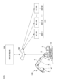
- FIG. 2 is a top view showing an example of a shovel.
- FIG. 2 is a diagram illustrating an example of a configuration for remote control of a shovel.
- FIG. 2 is a diagram illustrating an example of a hardware configuration of a shovel.
- FIG. 2 illustrates an example of a hardware configuration of an information processing device.
- FIG. 2 is a functional block diagram showing a first example of a functional configuration of the work support system.
- 11 is a diagram illustrating an example of a relationship between the timing of processing related to a motion plan for a shovel and the motion of a planned object.
- FIG. 1 illustrates an example of a work support system.
- FIG. 2 is a top view showing an example of a shovel.
- FIG. 2 is a diagram illustrating an example of a configuration for remote control of a shovel.
- FIG. 2 is a diagram illustrating an example of a hardware configuration of a shovel
- FIG. 13 is a diagram illustrating another example of the relationship between the timing of processing related to the operation plan of the shovel and the operation of the planned target.
- FIG. FIG. 11 is a state transition diagram showing an example of the transition of an operation of a shovel during slope construction work.
- FIG. 11 is a state transition diagram showing an example of the transition of the operation of a shovel during ground leveling work.
- FIG. 11 is a functional block diagram showing a second example of the functional configuration of the work support system.
- 10 is a flowchart illustrating an example of a process related to starting autonomous operation of a shovel.
- 1 is a main flowchart illustrating an example of a process related to a motion plan for a shovel and generation of a trajectory for a bucket.
- FIG. 2 is a diagram illustrating an example of an observation target area.
- 13 is a sub-flowchart illustrating an example of a process related to bucket trajectory generation.
- FIG. 13 is a diagram showing an example of cost conditions and operation parameters corresponding to a plurality of operation sections of an excavation operation of a shovel.
- 1 is a flowchart illustrating an example of a process related to operation control of a shovel.
- FIG. 1 An overview of an operation support system SYS according to this embodiment will be described with reference to FIGS. 1 to 3.
- FIG. 1 An overview of an operation support system SYS according to this embodiment will be described with reference to FIGS. 1 to 3.
- FIG. 1 An overview of an operation support system SYS according to this embodiment will be described with reference to FIGS. 1 to 3.
- FIG. 1 An overview of an operation support system SYS according to this embodiment will be described with reference to FIGS. 1 to 3.
- FIG. 1 is a diagram showing an example of an operation support system SYS.
- SYS operation support system
- FIG. 1 a left side view of the shovel 100 is shown.
- FIG. 2 is a top view showing an example of the shovel 100.
- FIG. 3 is a diagram showing an example of a configuration related to remote operation of the shovel 100.
- the direction in which the attachment AT extends when viewed from above the shovel 100 (the upward direction in FIG. 2) will be defined as "front,” and directions on the shovel 100 or directions seen from the shovel 100 may be described.
- the operation support system SYS includes an excavator 100, an information processing device 200, and a sensor group 300.
- the operation support system SYS uses the information processing device 200 to cooperate with the shovel 100 and provide support regarding the operation of the shovel 100.
- the operation support system SYS may include one or more excavators 100.
- the excavator 100 is a work machine that receives operation support in the operation support system SYS.
- the excavator 100 includes a lower running body 1, an upper rotating body 3, an attachment AT including a boom 4, an arm 5, and a bucket 6, and a cabin 10.
- the lower traveling body 1 uses crawlers 1C to travel the excavator 100.
- the crawlers 1C include a left crawler 1CL and a right crawler 1CR.
- the crawlers 1CL are hydraulically driven by a traveling hydraulic motor 1ML.
- the crawlers 1CL are hydraulically driven by a traveling hydraulic motor 1MR. This allows the lower traveling body 1 to travel on its own.
- the upper rotating body 3 is mounted on the lower running body 1 so as to be rotatable (freely rotatable) via the rotating mechanism 2.
- the upper rotating body 3 rotates relative to the lower running body 1 when the rotating mechanism 2 is hydraulically driven by a rotating hydraulic motor 2M.
- the boom 4 is attached to the front center of the upper rotating body 3 so that it can be raised and lowered around a rotation axis that runs along the left-right direction.
- the arm 5 is attached to the tip of the boom 4 so that it can rotate around a rotation axis that runs along the left-right direction.
- the bucket 6 is attached to the tip of the arm 5 so that it can rotate around a rotation axis that runs along the left-right direction.
- the bucket 6 is an example of an end attachment and is used, for example, for excavation work, slope work, and ground leveling work.
- the bucket 6 is attached to the tip of the arm 5 in a manner that allows it to be appropriately replaced depending on the work content of the shovel 100.
- a bucket of a different type from the bucket 6, such as a relatively large bucket, a bucket for slopes, a dredging bucket, etc. may be attached to the tip of the arm 5.
- an end attachment of a type other than a bucket, such as an agitator, breaker, crusher, etc. may be attached to the tip of the arm 5.
- a spare attachment such as a quick coupling or tilt rotator may be provided between the arm 5 and the end attachment.
- the boom 4, arm 5, and bucket 6 are hydraulically driven by a boom cylinder 7, arm cylinder 8, and bucket cylinder 9, respectively.
- the cabin 10 is a control room where an operator sits and operates the excavator 100.
- the cabin 10 is mounted, for example, on the front left side of the upper rotating body 3.
- the excavator 100 is equipped with a communication device 60 and can communicate with the information processing device 200 via a specified communication line NW.
- the communication line NW may include, for example, a local network (LAN: Local Area Network) at a work site.
- the communication line NW may also include a wide area network (WAN: Wide Area Network).
- Wide area networks include, for example, mobile communication networks ending in base stations, satellite communication networks using communication satellites, and Internet networks.
- the communication line NW may also include, for example, short-distance communication lines based on wireless communication standards such as Wi-Fi and Bluetooth (registered trademark).
- the excavator 100 operates driven elements such as the lower traveling body 1 (i.e., a pair of left and right crawlers 1CL, 1CR), upper rotating body 3, boom 4, arm 5, and bucket 6 in response to the operation of an operator in the cabin 10.
- the lower traveling body 1 i.e., a pair of left and right crawlers 1CL, 1CR
- upper rotating body 3 i.e., a pair of left and right crawlers 1CL, 1CR
- boom 4, arm 5, and bucket 6 in response to the operation of an operator in the cabin 10.
- the shovel 100 may be configured to be remotely operable from outside the shovel 100.
- the interior of the cabin 10 may be unmanned.
- the shovel 100 is dedicated to remote operation, the cabin 10 may be omitted.
- the operation of the operator includes at least one of the operation of the operating device 26 by the operator inside the cabin 10 and the remote operation by an external operator.
- remote operation includes a mode in which the shovel 100 is operated by operation input related to the actuator of the shovel 100 performed by a remote operation support device 400 capable of communicating with the shovel 100 via a communication line NW.
- the remote operation support device 400 may be provided separately from the information processing device 200, or may be the information processing device 200.
- the remote operation support device 400 is provided, for example, in a management center that manages the work of the shovel 100 from the outside.
- the remote operation support device 400 may also be a portable operation terminal, in which case the operator can remotely operate the shovel 100 while directly checking the work status of the shovel 100 from the vicinity of the shovel 100.
- the shovel 100 may transmit, for example, through the communication device 60 described below, an image (hereinafter, "peripheral image") showing the surroundings including the front of the shovel 100 based on an image output by an imaging device mounted on the shovel 100 to the remote operation support device 400.
- the shovel 100 may also transmit the image output by the imaging device to the remote operation support device 400 through the communication device 60, and the remote operation support device 400 may process the image received from the shovel 100 to generate a peripheral image.
- the remote operation support device 400 may then display the peripheral image showing the surroundings including the front of the shovel 100 on its own display device.
- Various information images (information screens) displayed on the output device 50 (display device) inside the cabin 10 of the shovel 100 may also be displayed on the display device of the remote operation support device 400.
- the excavator 100 may operate actuators and drive driven elements such as the lower traveling body 1, the upper rotating body 3, the boom 4, the arm 5, and the bucket 6 in response to a remote operation signal indicating the content of the remote operation received from the remote operation support device 400 by the communication device 60.
- Remote control may also include a mode in which the shovel 100 is operated by external voice input or gesture input to the shovel 100 by a person (e.g., a worker) around the shovel 100.
- the shovel 100 recognizes voices uttered by surrounding workers and gestures made by workers through a voice input device (e.g., a microphone) or a gesture input device (e.g., an imaging device) mounted on the shovel 100.
- the shovel 100 may then operate actuators according to the content of the recognized voices and gestures to drive driven elements such as the lower traveling body 1 (left and right crawlers 1C), upper rotating body 3, boom 4, arm 5, and bucket 6.
- the excavator 100 may also automatically operate the actuators regardless of the content of the operator's operation. This allows the excavator 100 to realize a function for automatically operating at least some of the driven elements such as the lower traveling body 1, the upper rotating body 3, and the attachment AT, i.e., a so-called “automatic driving function” or “machine control (MC) function.”
- the automatic driving function includes, for example, a semi-automatic driving function (operation assistance type MC function).
- the semi-automatic driving function is a function that automatically operates a driven element (actuator) other than the driven element (actuator) to be operated in response to the operation of the operator.
- the automatic driving function may also include a fully automatic driving function (fully automatic MC function).
- the fully automatic driving function is a function that automatically operates at least a part of a plurality of driven elements (hydraulic actuators) on the assumption that there is no operation from the operator.
- the fully automatic driving function is enabled in the shovel 100, the inside of the cabin 10 may be unmanned. Furthermore, when the shovel 100 is dedicated to fully automatic operation, the cabin 10 may be omitted.
- the semi-automatic driving function and the fully automatic driving function include, for example, a rule-based automatic driving function.
- the rule-based automatic driving function is an automatic driving function in which the operation content of the driven element (actuator) to be the target of automatic operation is automatically determined according to a rule that is specified in advance.
- the semi-automatic driving function and the fully automatic driving function may include an autonomous driving function.
- the autonomous driving function is a function in which the excavator 100 autonomously makes various decisions and determines the operation of the driven element (hydraulic actuator) that is the target of the autonomous driving based on the results of those decisions.
- the work of the shovel 100 may also be remotely monitored.
- a remote monitoring support device having the same functions as the remote operation support device 400 may be provided.
- the remote monitoring support device is, for example, the information processing device 200. This allows a monitor, who is a user of the remote monitoring support device, to monitor the status of the work of the shovel 100 while checking the surrounding images displayed on the display device of the remote monitoring support device. Also, for example, if the monitor determines it is necessary from the perspective of safety, he or she can use the input device of the remote monitoring support device to make a specified input, thereby intervening in the operation by the operator of the shovel 100 or automatic operation and bringing the shovel 100 to an emergency stop.
- the information processing device 200 communicates with the shovel 100 to cooperate with it and provide support for the operation of the shovel 100.
- the information processing device 200 is, for example, a server device or a management terminal device installed in a management office in the work site of the shovel 100, or in a management center that manages the operating status of the shovel 100 and is located in a place different from the work site of the shovel 100.
- the server device may be an on-premise server, a cloud server, or an edge server.
- the management terminal device may be, for example, a stationary terminal device such as a desktop PC (Personal Computer), or a portable terminal device (mobile terminal) such as a tablet terminal, a smartphone, or a laptop PC.
- a worker at the work site, a supervisor who supervises the work, or a manager who manages the work site can move around the work site carrying the portable information processing device 200.
- an operator can, for example, bring the portable information processing device 200 into the cabin of the shovel 100.
- the information processing device 200 acquires data on the operating state from the shovel 100. This enables the information processing device 200 to grasp the operating state of the shovel 100 and monitor the presence or absence of abnormalities in the shovel 100.
- the information processing device 200 can also display data on the operating state of the shovel 100 via, for example, a display device 208 described below, for a user to confirm.
- the information processing device 200 can also, for example, train a learning model to learn the operating state of the shovel 100, and generate a trained model for supporting the operation of the shovel 100.
- the information processing device 200 may also transmit to the shovel 100 various data such as programs and reference data used in the processing of the controller 30, etc., to the shovel 100. This allows the shovel 100 to perform various processes related to the operation of the shovel 100 using the various data downloaded from the information processing device 200.
- the sensor group 300 is installed at the work site of the shovel 100.
- the work target is, for example, soil and sand in the work area around the shovel 100.
- the operation support system SYS includes multiple shovels 100
- a sensor group 300 is provided for each shovel 100.
- multiple shovels 100 included in the operation support system SYS work at the same work site, one sensor group 300 may be shared by the multiple shovels 100.
- Sensor group 300 includes sensors 300-1 to 300-M (M: an integer of 2 or more). Sensors 300-1 to 300-M measure the state of objects at the work site around shovel 100 and acquire measurement data relating to the state. Objects at the work site include the work target around shovel 100 (soil and sand in the work area), as well as other shovels around shovel 100, work machines such as bulldozers, and work vehicles such as trucks for transporting soil and sand.
- the state of an object includes the shape and characteristics of the object.
- the sensors 300-1 to 300-M include, for example, a distance measurement sensor (distance sensor).
- Distance measurement sensors include, for example, LIDAR (Light Detecting and Ranging), millimeter wave radar, ultrasonic sensors, infrared sensors, etc.
- the sensors 300-1 to 300-M may also include, for example, a stereo camera, a TOF (Time Of Flight) camera, or other 3D cameras capable of acquiring data related to distance (depth) in addition to two-dimensional images.
- the sensors 300-1 to 300-M may also include a mixture of distance measurement sensors and 3D cameras. This allows the sensor group 300 to acquire measurement data representing the shape of objects at the work site around the shovel 100.
- sensors capable of acquiring measurement data representing the shape of objects such as distance measurement sensors and 3D cameras, may be referred to as "shape sensors" for convenience.
- the sensors 300-1 to 300-M may also include a multi-wavelength spectroscopic camera.
- Multi-wavelength spectroscopic cameras include, for example, multispectral cameras and hyperspectral cameras. This allows the sensor group 300 to acquire measurement data that represents the characteristics of objects at the work site around the shovel 100, such as the hardness and moisture content of soil and sand.
- characteristics sensors may be referred to as "characteristic sensors.”
- sensors 300-1 to 300-M include multiple shape sensors.
- the multiple shape sensors may be provided in different locations on the work site around the shovel 100, and such that the sensing range of each sensor overlaps with the sensing range of at least one other shape sensor.
- the other shape sensors may be able to obtain measurement data representing the shape of the object in that range. Therefore, the sensor group 300 can more reliably obtain measurement data representing the shape of objects in the work site around the shovel 100.
- the sensors 300-1 to 300-M may include multiple characteristic sensors.
- the multiple characteristic sensors may be provided in different locations in the work site around the shovel 100, and so that the sensing range of each sensor overlaps with at least one other characteristic sensor.
- the other shape sensors may be able to obtain measurement data representing the characteristics of the object in that range. Therefore, the sensor group 300 can more reliably obtain measurement data representing the characteristics of objects in the work site around the shovel 100.
- sensors 300-1 to 300-M may include a sensor having both the functions of a shape sensor and a characteristic sensor (hereinafter, "integrated sensor”).
- sensors 300-1 to 300-M may include multiple integrated sensors.
- the multiple characteristic sensors may be provided at different locations in the work site around shovel 100, and each of the sensing ranges may overlap with at least one other characteristic sensor.
- the sensor group 300 may simply include only one shape sensor or one characteristic sensor.
- the operation support system SYS may simply include only one sensor capable of acquiring measurement data regarding the state of objects at the work site around the shovel 100.
- Sensors 300-1 to 300-M may be fixed to the work site around shovel 100, or may be mounted on a mobile object capable of moving within the work site around shovel 100.
- Mobile objects include, for example, work machines and work vehicles that move within the work site.
- Mobile objects that can move within the work site may also include, for example, flying objects such as drones that fly above the work site.
- the output (measurement data) of the sensors 300-1 to 300-M is taken into the information processing device 200 through the communication line NW.
- the output of the sensors 300-1 to 300-M is taken into the information processing device 200 directly through the communication line NW, for example.
- the output of the sensors 300-1 to 300-M may also be taken into the shovel 100 once through the communication line NW, and then taken into the information processing device 200 via the shovel 100. If the sensors 300-1 to 300-M are mounted on a specific device, such as the above-mentioned mobile object, the output of the sensors 300-1 to 300-M may also be taken into the specific device once, and then taken into the information processing device 200 from that device.
- the hardware configuration of the remote operation support device 400 may be the same as that of the information processing device 200. Therefore, illustrations and descriptions of the hardware configuration of the remote operation support device 400 will be omitted.
- FIG. 4 is a block diagram showing an example of a hardware configuration of the shovel 100.
- the excavator 100 includes various components, such as a hydraulic drive system for hydraulically driving the driven elements, an operation system for operating the driven elements, a user interface system for exchanging information with the user, a communication system for communicating with the outside world, and a control system for various controls.
- the hydraulic drive system of the excavator 100 includes hydraulic actuators HA that hydraulically drive each of the driven elements, such as the lower traveling structure 1 (left and right crawlers 1C), upper rotating structure 3, boom 4, arm 5, and bucket 6, as described above.
- the hydraulic drive system of the excavator 100 according to this embodiment also includes an engine 11, a regulator 13, a main pump 14, and a control valve 17.
- the hydraulic actuator HA includes travel hydraulic motors 1ML, 1MR, swing hydraulic motor 2M, boom cylinder 7, arm cylinder 8, and bucket cylinder 9.
- the shovel 100 a part or all of the hydraulic actuator HA may be replaced with an electric actuator.
- the shovel 100 may be a hybrid shovel or an electric shovel.
- the engine 11 is the prime mover of the excavator 100 and the main power source in the hydraulic drive system.
- the engine 11 is, for example, a diesel engine that uses light oil as fuel.
- the engine 11 is mounted, for example, at the rear of the upper rotating body 3.
- the engine 11 rotates at a constant speed at a preset target speed under direct or indirect control by the controller 30 (described later), for example, and drives the main pump 14 and the pilot pump 15.
- prime movers e.g., electric motors
- the excavator 100 instead of or in addition to the engine 11.
- the regulator 13 controls (adjusts) the discharge volume of the main pump 14 under the control of the controller 30. For example, the regulator 13 adjusts the angle of the swash plate of the main pump 14 (hereinafter, the "tilt angle") in response to a control command from the controller 30.
- the main pump 14 supplies hydraulic oil to the control valve 17 through a high-pressure hydraulic line.
- the main pump 14 is mounted, for example, at the rear of the upper rotating body 3, similar to the engine 11. As described above, the main pump 14 is driven by the engine 11.
- the main pump 14 is, for example, a variable displacement hydraulic pump, and as described above, under the control of the controller 30, the tilt angle of the swash plate is adjusted by the regulator 13 to adjust the stroke length of the piston, thereby controlling the discharge flow rate and discharge pressure.
- the control valve 17 drives the hydraulic actuators HA in response to the operator's operation of the operating device 26, the contents of remote operation, or operation commands corresponding to the automatic operation function.
- the control valve 17 is mounted, for example, in the center of the upper rotating body 3.
- the control valve 17 is connected to the main pump 14 via a high-pressure hydraulic line, and selectively supplies hydraulic oil supplied from the main pump 14 to each hydraulic actuator in response to the operator's operation or operation commands corresponding to the automatic operation function.
- the control valve 17 includes multiple control valves (directional control valves) that control the flow rate and flow direction of the hydraulic oil supplied from the main pump 14 to each hydraulic actuator HA.
- the operating system of the excavator 100 includes a pilot pump 15 , an operating device 26 , a hydraulic control valve 31 , a shuttle valve 32 , and a hydraulic control valve 33 .
- the pilot pump 15 supplies pilot pressure to various hydraulic equipment via a pilot line 25.
- the pilot pump 15 is mounted, for example, at the rear of the upper rotating body 3, similar to the engine 11.
- the pilot pump 15 is, for example, a fixed displacement hydraulic pump, and is driven by the engine 11 as described above.
- the pilot pump 15 may be omitted.
- the relatively high pressure hydraulic oil discharged from the main pump 14 is reduced in pressure by a specified pressure reducing valve, and the relatively low pressure hydraulic oil is supplied to various hydraulic equipment as pilot pressure.
- the operating device 26 is provided near the cockpit of the cabin 10, and is used by the operator to operate the various driven elements. Specifically, the operating device 26 is used by the operator to operate the hydraulic actuators HA that drive the respective driven elements, and as a result, the operator can operate the driven elements that are the targets of the drive of the hydraulic actuators HA.
- the operating device 26 includes pedal devices and lever devices for operating the respective driven elements (hydraulic actuators HA).
- the operating device 26 is of a hydraulic pilot type. Specifically, the operating device 26 uses hydraulic oil supplied from the pilot pump 15 through the pilot line 25 and the pilot line 25A branching therefrom, and outputs pilot pressure corresponding to the operation to the secondary pilot line 27A.
- the pilot line 27A is connected to one inlet port of the shuttle valve 32, and is connected to the control valve 17 via the pilot line 27 connected to the outlet port of the shuttle valve 32.
- pilot pressure corresponding to the operation of various driven elements (hydraulic actuators HA) in the operating device 26 can be input to the control valve 17 via the shuttle valve 32. Therefore, the control valve 17 can drive each hydraulic actuator HA according to the operation of the operating device 26 by an operator or the like.
- the operating device 26 may also be electric.
- the pilot line 27A, shuttle valve 32, and hydraulic control valve 33 are omitted.
- the operating device 26 outputs an electric signal (hereinafter, "operation signal") according to the operation content, and the operation signal is input to the controller 30.
- the controller 30 then outputs a control command according to the content of the operation signal, that is, a control signal according to the operation content for the operating device 26, to the hydraulic control valve 31.
- a pilot pressure according to the operation content of the operating device 26 is input from the hydraulic control valve 31 to the control valve 17, and the control valve 17 can drive each hydraulic actuator HA according to the operation content of the operating device 26.
- control valves built into the control valve 17 that drive the respective hydraulic actuators HA may be of the electromagnetic solenoid type.
- the operation signal output from the operating device 26 may be directly input to the control valve 17 (i.e., to the electromagnetic solenoid type control valve).
- part or all of the hydraulic actuator HA may be replaced with an electric actuator.
- the controller 30 may output a control command corresponding to the operation content of the operating device 26 or the remote operation content specified by the remote operation signal to the electric actuator or a driver that drives the electric actuator.
- the operating device 26 may be omitted.
- the hydraulic control valve 31 is provided for each driven element (hydraulic actuator HA) to be operated by the operating device 26 and for each driving direction of the driven element (hydraulic actuator HA) (e.g., the raising direction and lowering direction of the boom 4).
- the hydraulic control valve 31 may be provided, for example, in the pilot line 25B between the pilot pump 15 and the control valve 17, and may be configured to change its flow area (i.e., the cross-sectional area through which the hydraulic oil can flow).
- the hydraulic control valve 31 can indirectly apply a predetermined pilot pressure corresponding to a control signal from the controller 30 to the control valve 17 through the shuttle valve 32 between the pilot line 27B and the pilot line 27. Therefore, for example, the controller 30 can supply pilot pressure from the hydraulic control valve 31 to the control valve 17 in response to an operation command corresponding to the automatic driving function, thereby realizing the operation of the excavator 100 using the automatic driving function.
- the controller 30 may also control the hydraulic control valve 31 to realize remote operation of the excavator 100. Specifically, the controller 30 outputs a control signal corresponding to the content of the remote operation specified by the remote operation signal received from the remote operation support device 400 to the hydraulic control valve 31 via the communication device 60. As a result, the controller 30 can supply pilot pressure corresponding to the content of the remote operation from the hydraulic control valve 31 to the control valve 17, thereby realizing the operation of the excavator 100 based on the remote operation by the operator.
- the controller 30 can supply pilot pressure corresponding to the operation content (operation signal) of the operating device 26 directly to the control valve 17 from the hydraulic control valve 31, thereby realizing the operation of the excavator 100 based on the operation of the operator.
- the shuttle valve 32 has two inlet ports and one outlet port, and outputs hydraulic oil having the higher pilot pressure of the two pilot pressures input to the inlet ports to the outlet port.
- the shuttle valve 32 is provided for each driven element (hydraulic actuator HA) to be operated by the operating device 26 and for each driving direction of the driven element (hydraulic actuator HA) in the same manner as the hydraulic control valve 31.
- two shuttle valves 32 are provided for each double-acting hydraulic actuator HA for driving the lower traveling body 1, upper rotating body 3, boom 4, arm 5, bucket 6, etc.
- One of the two inlet ports of the shuttle valve 32 is connected to the secondary pilot line 27A of the operating device 26 (specifically, the above-mentioned lever device and pedal device included in the operating device 26), and the other is connected to the secondary pilot line 27B of the hydraulic control valve 31.
- the outlet port of the shuttle valve 32 is connected to the pilot port of the corresponding control valve of the control valve 17 through the pilot line 27.
- the corresponding control valve is a control valve that drives the hydraulic actuator HA that is the operation target of the above-mentioned lever device or pedal device connected to one inlet port of the shuttle valve 32.
- each of these shuttle valves 32 can apply the higher of the pilot pressure of the pilot line 27A on the secondary side of the operating device 26 and the pilot pressure of the pilot line 27B on the secondary side of the hydraulic control valve 31 to the pilot port of the corresponding control valve.
- the controller 30 can control the corresponding control valve regardless of the operator's operation of the operating device 26 by outputting a pilot pressure higher than the pilot pressure on the secondary side of the operating device 26 from the hydraulic control valve 31. Therefore, the controller 30 can control the operation of the driven elements (lower traveling body 1, upper rotating body 3, boom 4, arm 5, bucket 6) regardless of the operating state of the operating device 26 by the operator, thereby realizing an automatic driving function or a remote operation function.
- the hydraulic control valve 33 is provided in the pilot line 27A that connects the operating device 26 and the shuttle valve 32.
- the hydraulic control valve 33 is configured to be able to change its flow area, for example.
- the hydraulic control valve 33 operates in response to a control signal input from the controller 30.
- the controller 30 can forcibly reduce the pilot pressure output from the operating device 26 when the operating device 26 is being operated by the operator. Therefore, even when the operating device 26 is being operated, the controller 30 can forcibly suppress or stop the operation of the hydraulic actuator HA corresponding to the operation of the operating device 26.
- the controller 30 can reduce the pilot pressure output from the operating device 26 to make it lower than the pilot pressure output from the hydraulic control valve 31.
- the controller 30 can reliably apply a desired pilot pressure to the pilot port of the control valve in the control valve 17, for example, regardless of the operation content of the operating device 26. Therefore, for example, the controller 30 can more appropriately realize the automatic operation function and remote control function of the excavator 100 by controlling the hydraulic control valve 33 in addition to the hydraulic control valve 31.
- the user interface system of the shovel 100 includes an operation device 26 , an output device 50 , and an input device 52 .
- the output device 50 outputs various information to a user of the excavator 100 (e.g., an operator of the cabin 10 or an external remote control operator) and people in the vicinity of the excavator 100 (e.g., a worker or a driver of a work vehicle).
- a user of the excavator 100 e.g., an operator of the cabin 10 or an external remote control operator
- people in the vicinity of the excavator 100 e.g., a worker or a driver of a work vehicle.
- the output device 50 includes lighting equipment and display devices that output various information in a visual manner.
- Lighting equipment is, for example, a warning light (indicator lamp), etc.
- Display devices are, for example, a liquid crystal display and an organic EL (Electroluminescence) display, etc.
- the lighting equipment and display devices may be provided inside the cabin 10 and output various information in a visual manner to an operator, etc. inside the cabin 10.
- the lighting equipment and display devices may be provided, for example, on the side of the upper rotating body 3 and output various information in a visual manner to workers, etc. around the excavator 100.
- the output device 50 may also include a sound output device that outputs various information by auditory means (see FIG. 7). Sound output devices include, for example, buzzers and speakers.
- the sound output device may be provided, for example, at least one of the inside and outside of the cabin 10, and may output various information by auditory means to an operator inside the cabin 10 or to people (workers, etc.) around the excavator 100.
- the output device 50 may also include a device that outputs various information in a tactile manner, such as by vibration of the cockpit.
- the input device 52 receives various inputs from the user of the excavator 100, and signals corresponding to the received inputs are input to the controller 30.
- the input device 52 is provided inside the cabin 10 and receives inputs from an operator or the like inside the cabin 10.
- the input device 52 may also be provided, for example, on the side of the upper rotating body 3 and receives inputs from workers or the like in the vicinity of the excavator 100.
- the input device 52 includes an operation input device that accepts input from a user through mechanical operation.
- the operation input device may include a touch panel mounted on the display device, a touch pad installed around the display device, a button switch, a lever, a toggle, a knob switch provided on the operation device 26 (lever device), etc.
- the input device 52 may also include an audio input device that accepts audio input from the user.
- the audio input device may include, for example, a microphone.
- the input device 52 may also include a gesture input device that accepts gesture input from the user.
- the gesture input device includes, for example, an imaging device that captures an image of a gesture made by the user.
- the input device 52 may also include a biometric input device that accepts biometric input from the user.
- the biometric input includes, for example, input of biometric information such as the user's fingerprint or iris.
- the communication system of the shovel 100 includes a communication device 60 .
- the communication device 60 connects to an external communication line NW and communicates with a device provided separately from the shovel 100.
- the device provided separately from the shovel 100 may include a device outside the shovel 100, as well as a portable terminal device (mobile terminal) brought into the cabin 10 by the user of the shovel 100.
- the communication device 60 may include, for example, a mobile communication module conforming to standards such as 4G ( 4th Generation) and 5G ( 5th Generation).
- the communication device 60 may also include, for example, a satellite communication module.
- the communication device 60 may also include, for example, a WiFi communication module or a Bluetooth (registered trademark) communication module.
- the communication device 60 may include multiple communication devices according to the types of the communication lines NW.
- the communication device 60 communicates with external devices such as the information processing device 200 and the remote operation support device 400 at the work site through a local communication line established at the work site.
- the local communication line is, for example, a local 5G (so-called local 5G) mobile communication line established at the work site or a local network using Wi-Fi 6.
- the communication device 60 may also communicate with an information processing device 200 or a remote operation support device 400 outside the work site via a wide area communication line that includes the work site, i.e., a wide area network.
- control system of the shovel 100 includes a controller 30.
- the control system of the shovel 100 according to this embodiment also includes an operating pressure sensor 29, a sensor 40, and sensors S1 to S9.
- the controller 30 performs various controls related to the excavator 100.
- the controller 30 may be realized by any hardware or any combination of hardware and software.
- the controller 30 includes an auxiliary storage device 30A, a memory device 30B, a CPU (Central Processing Unit) 30C, and an interface device 30D, which are connected by a bus BS1.
- auxiliary storage device 30A a memory device 30B
- CPU Central Processing Unit
- interface device 30D an interface device 30D
- the auxiliary storage device 30A is a non-volatile storage means that stores the programs to be installed as well as necessary files, data, etc.
- the auxiliary storage device 30A is, for example, an EEPROM (Electrically Erasable Programmable Read-Only Memory) or flash memory.
- the memory device 30B loads the program from the auxiliary storage device 30A so that the program can be read by the CPU 30C.
- the memory device 30B is, for example, a static random access memory (SRAM).
- the CPU 30C for example, executes a program loaded into the memory device 30B and realizes various functions of the controller 30 according to the program's instructions.
- the interface device 30D functions, for example, as a communication interface for connecting to a communication line inside the excavator 100.
- the interface device 30D may include multiple different types of communication interfaces according to the type of communication line to be connected.
- the interface device 30D also functions as an external interface for reading data from a recording medium and writing data to the recording medium.
- the recording medium is, for example, a dedicated tool connected to a connector installed inside the cabin 10 via a detachable cable.
- the recording medium may also be a general-purpose recording medium, such as an SD memory card or a USB (Universal Serial Bus) memory.
- a program that realizes various functions of the controller 30 can be provided, for example, by a portable recording medium and installed in the auxiliary storage device 30A of the controller 30.
- the program may also be downloaded from another computer (for example, the information processing device 200) outside the excavator 100 via the communication device 60 and installed in the auxiliary storage device 30A.
- controller 30 may be realized by another controller (control device). In other words, the functions of the controller 30 may be realized in a distributed manner by multiple controllers mounted on the excavator 100.
- the operating pressure sensor 29 detects the pilot pressure on the secondary side (pilot line 27A) of the hydraulic pilot type operating device 26, i.e., the pilot pressure corresponding to the operating state of each driven element (hydraulic actuator) in the operating device 26.
- the detection signal of the pilot pressure by the operating pressure sensor 29 corresponding to the operating state of each driven element (hydraulic actuator HA) in the operating device 26 is taken into the controller 30.
- the operating pressure sensor 29 is omitted. This is because the controller 30 can grasp the operating state of each driven element through the operating device 26 based on the operating signal received from the operating device 26.
- the sensor 40 acquires measurement data, for example, regarding the shape of objects around the shovel 100.
- the senor 40 is a shape sensor, such as a distance sensor or a 3D camera, capable of acquiring measurement data representing the shape of objects around the shovel 100.
- the sensor 40 may be an integrated sensor that has the function of a characteristic sensor, such as a multi-wavelength spectroscopic camera, capable of acquiring measurement data representing the characteristics of objects around the shovel 100, in addition to the function of a shape sensor.
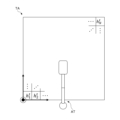
- the sensor 40 includes sensors 40F, 40B, 40L, and 40R.
- Sensor 40F measures the state (shape and characteristics) of an object in front of the upper rotating body 3.
- Sensor 40B measures the state of an object on the upper rotating body 3.
- Sensor 40L measures the state of an object to the left of the upper rotating body 3.
- Sensor 40R measures the state of an object to the right of the upper rotating body 3. In this way, the sensor 40 can measure the state of objects in a range around the shovel 100, that is, an angular direction of 360 degrees, when viewed from above the shovel 100.
- the sensors 40F, 40B, 40L, and 40R may be collectively or individually referred to as "sensor 40X.”
- the output data of the sensor 40 (sensor 40X) (i.e., measurement data relating to the state of objects around the shovel 100) is input to the controller 30 via a one-to-one communication line or an on-board network. This allows the controller 30 to grasp, for example, the shape, characteristics, and other state of objects around the shovel 100 based on the output data of the sensor 40X.
- sensors 40B, 40L, and 40R may be omitted.
- the sensor S1 is attached to the boom 4 and measures the attitude of the boom 4.
- the sensor S1 outputs measurement data representing the attitude of the boom 4.
- the attitude of the boom 4 is, for example, the attitude angle around the rotation axis of the base end corresponding to the connection part of the boom 4 with the upper rotating body 3 (hereinafter, "boom angle").
- the sensor S1 includes, for example, a rotary potentiometer, a rotary encoder, an acceleration sensor, an angular acceleration sensor, a six-axis sensor, an IMU (Inertial Measurement Unit), etc. The same may be true for the sensors S2 to S4 below.
- the sensor S1 may also include a cylinder sensor that detects the extension/retraction position of the boom cylinder 7. The same may be true for the sensors S2 and S3 below.
- the output of the sensor S1 (measurement data representing the attitude of the boom 4) is taken into the controller 30. This allows the controller 30 to grasp the attitude of the boom 4.
- Sensor S2 is attached to arm 5 and measures the posture of arm 5.
- Sensor S2 outputs measurement data representing the posture of arm 5.
- the posture of arm 5 is, for example, the posture angle around the rotation axis of the base end corresponding to the connection part of arm 5 with boom 4 (hereinafter referred to as "arm angle").
- the output of sensor S2 (measurement data representing the posture of arm 5) is input to controller 30. This allows controller 30 to grasp the posture of arm 5.
- Sensor S3 is attached to bucket 6 and measures the attitude of bucket 6.
- Sensor S3 outputs measurement data that indicates the attitude of bucket 6.
- the attitude of bucket 6 is, for example, the attitude angle around the rotation axis of the base end that corresponds to the connection part of bucket 6 with arm 5 (hereinafter, "arm angle").
- the output of sensor S3 (measurement data that indicates the attitude of bucket 6) is input to controller 30. This allows controller 30 to grasp the attitude of bucket 6.
- the sensor S4 measures the attitude of the shovel 100's body (e.g., the upper rotating body 3).
- the sensor S4 outputs measurement data representing the attitude of the shovel 100's body.
- the attitude of the shovel 100's body is, for example, the inclination of the body relative to a predetermined reference plane (e.g., a horizontal plane).
- the sensor S4 is attached to the upper rotating body 3 and measures the inclination angles of the shovel 100 about two axes in the front-rear and left-right directions (hereinafter, "front-rear inclination angle" and "left-right inclination angle”).
- the output of the sensor S4 (measurement data representing the attitude of the shovel 100's body) is input to the controller 30. This allows the controller 30 to grasp the attitude (inclination) of the body (upper rotating body 3).
- Sensor S5 is attached to the upper rotating body 3 and measures the rotation state of the upper rotating body 3.
- Sensor S5 outputs measurement data representing the rotation state of the upper rotating body 3.
- Sensor S5 measures, for example, the rotation angular velocity and rotation angle of the upper rotating body 3.
- Sensor S5 includes, for example, a gyro sensor, a resolver, a rotary encoder, etc.
- the output of sensor S5 (measurement data representing the rotation state of the upper rotating body 3) is input to controller 30. This allows controller 30 to grasp the rotation state of the upper rotating body 3, such as the rotation angle.
- the controller 30 can grasp (estimate) the position of the tip of the attachment AT (bucket 6) based on the outputs of the sensors S1 to S5.
- sensor S4 includes a gyro sensor, a six-axis sensor, an IMU, or the like capable of detecting angular velocity around three axes
- the rotation state e.g., rotation angular velocity
- sensor S5 may be omitted.
- the sensor S6 measures the position of the excavator 100.
- the sensor S6 may measure the position in world (global) coordinates, or in local coordinates at the work site.
- the sensor S6 is, for example, a GNSS (Global Navigation Satellite System) sensor.
- the sensor S6 is a transceiver that communicates with equipment that serves as a reference for the work site position and is capable of outputting a signal corresponding to the position relative to the reference.
- the output of the sensor S6 is taken into the controller 30.
- Sensor S7 measures the pressure (cylinder pressure) in the oil chamber of boom cylinder 7.
- Sensor S7 includes, for example, a sensor that measures the cylinder pressure (rod pressure) in the oil chamber on the rod side of boom cylinder 7, and a sensor that measures the cylinder pressure (bottom pressure) in the oil chamber on the bottom side.
- the output of sensor S7 (measurement data of the cylinder pressure of boom cylinder 7) is taken into controller 30.
- Sensor S8 measures the pressure (cylinder pressure) in the oil chamber of arm cylinder 8.
- Sensor S8 includes, for example, a sensor that measures the cylinder pressure (rod pressure) in the oil chamber on the rod side of arm cylinder 8, and a sensor that measures the cylinder pressure (bottom pressure) in the oil chamber on the bottom side of arm cylinder 8.
- the output of sensor S8 (measurement data of the cylinder pressure of arm cylinder 8) is taken into controller 30.
- Sensor S9 measures the pressure (cylinder pressure) in the oil chamber of bucket cylinder 9.
- Sensor S9 includes, for example, a sensor that measures the cylinder pressure (rod pressure) in the oil chamber on the rod side of bucket cylinder 9, and a sensor that measures the cylinder pressure (bottom pressure) in the oil chamber on the bottom side of bucket cylinder 9.
- the output of sensor S9 (measurement data of the cylinder pressure of bucket cylinder 9) is input to controller 30.
- the controller 30 can grasp the load state acting on the attachment AT based on the output of the sensors S7 to S9.
- the load acting on the attachment AT includes, for example, the reaction force acting on the bucket 6 from the work target (soil on the ground) and the weight of the soil contained in the bucket 6.
- FIG. 5 is a block diagram showing an example of a hardware configuration of the information processing device 200. As shown in FIG. 5
- the functions of the information processing device 200 are realized by any hardware or any combination of hardware and software.
- the information processing device 200 includes an external interface 201, an auxiliary storage device 202, a memory device 203, a CPU 204, a high-speed calculation device 205, a communication interface 206, an input device 207, a display device 208, and a sound output device 209. These are connected by a bus BS2.
- the external interface 201 functions as an interface for reading data from and writing data to the recording medium 201A.
- Examples of the recording medium 201A include flexible disks, CDs (Compact Discs), DVDs (Digital Versatile Discs), BDs (Blu-ray (registered trademark) Discs), SD memory cards, USB memories, etc. This allows the information processing device 200 to read various data used in processing through the recording medium 201A, store the data in the auxiliary storage device 202, and install programs that realize various functions.
- the information processing device 200 may obtain various data and programs used in processing from an external device via the communication interface 206.
- the auxiliary storage device 202 stores various installed programs as well as files and data necessary for various processes.
- the auxiliary storage device 202 includes, for example, a hard disc drive (HDD), a solid state disc (SSD), flash memory, etc.
- the memory device 203 When an instruction to start a program is received, the memory device 203 reads out and stores the program from the auxiliary storage device 202.
- the memory device 203 includes, for example, a dynamic random access memory (DRAM) or an SRAM.
- DRAM dynamic random access memory
- SRAM static random access memory
- the CPU 204 executes various programs loaded from the auxiliary storage device 202 to the memory device 203, and realizes various functions related to the information processing device 200 according to the programs.
- the high-speed calculation device 205 works in conjunction with the CPU 204 to perform calculation processing at a relatively high speed.
- the high-speed calculation device 205 includes, for example, a GPU (Graphics Processing Unit), an ASIC (Application Specific Integrated Circuit), an FPGA (Field-Programmable Gate Array), etc.
- the high-speed calculation device 205 may be omitted depending on the required calculation processing speed.
- the communication interface 206 is used as an interface for connecting to an external device so as to be able to communicate with it. This allows the information processing device 200 to communicate with an external device, such as the shovel 100, through the communication interface 206.
- the communication interface 206 may also have multiple types of communication interfaces depending on the communication method between the connected device, etc.
- the input device 207 accepts various inputs from the user.
- the input device 207 includes a remote control operation device for remotely operating the excavator 100.
- the input device 207 includes, for example, an input device that accepts mechanical operation input from a user (hereinafter, "operation input device").
- the operation device for remote operation may be an operation input device.
- the operation input device includes, for example, a button, a toggle, a lever, a keyboard, a mouse, a touch panel implemented in the display device 208, a touch pad provided separately from the display device 208, etc.
- the input device 207 may also include a voice input device capable of receiving voice input from a user.
- the voice input device may include, for example, a microphone capable of collecting the user's voice.
- the input device 207 may also include a gesture input device capable of accepting gesture input from a user.
- the gesture input device includes, for example, a camera capable of capturing an image of the user's gesture.
- the input device 207 may also include a biometric input device capable of accepting biometric input from a user.
- the biometric input device includes, for example, a camera capable of acquiring image data containing information about the user's fingerprint or iris.
- the display device 208 displays an information screen and an operation screen for a user of the information processing device 200.
- the display device 208 is, for example, a liquid crystal display or an organic EL (Electroluminescence) display.
- the sound output device 209 conveys various information to the user of the information processing device 200 by sound.
- the sound output device 209 is, for example, a buzzer, an alarm, a speaker, etc.
- FIG. 6 is a functional block diagram showing a first example of the functional configuration of the operation support system SYS.
- the trajectory of the working part of the shovel 100 is used to include both the path (i.e., the track) that the working part of the shovel 100 has already traveled, and the path that it may travel in the future.
- the working part corresponds to the tip of the AT attachment that is used to make changes to the work target. Specifically, the working part is the bucket 6.
- the shovel 100 includes an assistance device 150.
- the assistance device 150 provides assistance to the shovel 100 operating using an autonomous driving function in carrying out tasks.
- the support device 150 includes a controller 30, a hydraulic control valve 31, a sensor 40, an output device 50, an input device 52, and sensors S1 to S9.
- the support device 150 may include a communication device 60 instead of or in addition to the input device 52.
- the controller 30 includes, as functional units, an operation log providing unit 301 and a work support unit 302.
- the operation support system SYS includes a plurality of shovels 100
- the former shovel 100 only has the function of acquiring the operation log of the shovel 100 and providing it to the information processing device 200, which is used for the work support function of the latter shovel 100. The same may be true for the second example described below.
- the information processing device 200 includes, as functional units, a log acquisition unit 2001, a simulator unit 2002, a log storage unit 2003, a teacher data generation unit 2004, a machine learning unit 2005, a trained model storage unit 2006, and a distribution unit 2007.
- the operation log providing unit 301 is a functional unit that acquires an operation log during a specific operation of the excavator 100 and provides it to the information processing device 200.
- multiple predetermined actions are predefined.
- the multiple predetermined actions include excavation, boom-raising and swinging, boom-lowering and swinging, soil dumping, broom action, etc.
- the multiple predetermined actions include excavation, soil dumping, sweeping, horizontal pulling, compaction, broom action, etc.
- the multiple predetermined actions may include excavation, soil dumping, slope pulling, compaction, etc.
- the slope pulling action corresponds to the horizontal pulling action of leveling work, and is an action of moving the attachment AT so that the tip (toe) of the bucket 6 is pulled toward the machine body side (upper rotating body 3 side) along the slope corresponding to the target construction surface.
- the sweeping action is, for example, an action of operating the attachment AT and pushing the bucket 6 forward along the ground, thereby sweeping soil forward with the back of the bucket 6.
- the attachment AT performs a boom 4 lowering action and an arm 5 opening action.
- the horizontal pulling operation is, for example, an operation of operating the attachment AT and moving the tip of the bucket 6 so as to pull it toward the front substantially horizontally along the ground, thereby leveling out the unevenness of the ground (surface of the terrain).
- the attachment AT performs a lifting operation of the boom 4 and a closing operation of the arm 5.
- the rolling operation is, for example, an operation of operating the attachment AT and pressing the ground with the back surface of the bucket 6.
- the rolling operation may also be an operation of pressing the ground by striking the back surface of the bucket 6 against the ground while moving the bucket 6 up and down.
- the rolling operation may also be an operation of pushing the bucket 6 forward along the ground, sweeping out the soil to a predetermined position in front with the back surface of the bucket 6, and then pressing the ground at the predetermined position with the back surface of the bucket 6.
- the attachment AT performs a lowering operation of the boom 4 when pressing the ground.
- the broom operation is, for example, an operation of operating the upper rotating body 3 and rotating the bucket 6 left and right while it is aligned along the ground.
- the broom operation may be, for example, an operation in which the attachment AT and the upper rotating body 3 are operated to push the bucket 6 forward while rotating the bucket 6 alternately left and right along the ground.
- the upper rotating body 3 alternately rotates left and right.
- the attachment AT may lower the boom 4 and open the arm 5, as in the sweeping operation.
- the operation log of the shovel 100 is time-series data representing the operating state of the shovel 100.
- the operation log of the shovel 100 includes time-series data representing the operation contents of the operator.
- the time-series data representing the operation contents of the operator is, for example, time-series output data of the operating pressure sensor 29 corresponding to the hydraulic pilot type operating device 26 or time-series output data (operation signal data) of the operating device 26 corresponding to the electric type operating device 26.
- the operation log of the shovel 100 may also be time-series output data of the sensors S1 to S5 or time-series data representing the posture state of the shovel 100 acquired from the output data of the sensors S1 to S5.
- the operation log providing unit 301 may also obtain an operation log when an operator who has a long history of operating the shovel 100 and is relatively experienced (hereinafter, for convenience, referred to as an "expert") operates the shovel 100, and provide the operation log to the information processing device 200.
- This makes it possible to generate a learned model LM3 capable of reproducing the operation of the shovel 100 operated by an expert, by machine learning based on the operation log of the shovel 100, as described below.
- the operation log providing unit 301 includes an operation log recording unit 301A, an operation log storage unit 301B, and an operation log transmission unit 301C.
- the operation log recording unit 301A acquires an operation log during a specific operation of the shovel 100 and records it in the operation log storage unit 301B. For example, each time a specific operation of the shovel 100 is performed, the operation log recording unit 301A records the operation log during that operation in the operation log storage unit 301B.
- the operation log storage unit 301B stores the operation log of the shovel 100.
- the operation log storage unit 301B stores, for each predetermined operation performed by the shovel 100, an operation log and data on the time (date and time) when the predetermined operation was performed, linked to each other.
- the data on the time when the predetermined operation was performed includes data on both the start and end times of the predetermined operation of the shovel 100.
- the operation log storage unit 301B stores, for each predetermined operation performed by the shovel 100, an operation log, data on the time when the predetermined operation was performed, and data on identification information of the performed predetermined operation, linked to each other.
- data linked to the operation log of the shovel 100 may be referred to as "associated data" for convenience.
- the operation log storage unit 301B accumulates record data representing the correspondence between the operation log and associated data for each predetermined operation performed by the shovel 100, thereby constructing a database of operation logs when the predetermined operation of the shovel 100 is performed.
- the operation log of the operation log storage unit 301B that has already been transmitted to the information processing device 200 by the operation log transmission unit 301C described below may be deleted afterwards.
- the operation log transmission unit 301C transmits the operation log stored in the operation log storage unit 301B when the shovel 100 performs a predetermined operation and the associated data linked to the operation log to the information processing device 200 via the communication device 60.
- the operation log transmission unit 301C may also transmit record data indicating the correspondence between the operation log of the shovel 100 and the associated data for each predetermined operation performed by the shovel 100 to the information processing device 200.
- the operation log transmission unit 301C transmits the untransmitted operation log and associated data of the shovel 100 stored in the operation log storage unit 301B to the information processing device 200 in response to a request to transmit the operation log of the shovel 100 received from the information processing device 200.
- the operation log transmission unit 301C may also automatically transmit the untransmitted operation log and associated data of the shovel 100 stored in the operation log storage unit 301B to the information processing device 200 at a predetermined timing.
- the predetermined timing is, for example, when the shovel 100 stops operating (key switch off) or starts operating (key switch on), etc.
- the log acquisition unit 2001 acquires logs when the excavator 100 performs a specified operation.
- the log when the shovel 100 executes a predetermined operation includes an operation log when the shovel 100 executes the predetermined operation and a status log of the work target.
- the status log of the work target includes time-series data that indicates the status of the work target before, during, and after the execution of the predetermined operation of the shovel 100.
- the status of the work target includes the shape (topography) of the soil and sand that are the target of the work and the properties of the soil.
- the properties of the soil may include, for example, the hardness of the soil, the moisture content of the soil, the size of the soil particles (grain size), and the angle of repose of the soil.
- the operation log when the shovel 100 executes a predetermined operation is uploaded from the shovel 100.
- the status log of the work target when the shovel 100 executes a predetermined operation is obtained based on the measurement data uploaded from the sensor group 300 and the associated data uploaded from the shovel 100 (data on the time when the predetermined operation was executed).
- the status log of the work target may be acquired based on measurement data from the sensor 40 of the shovel 100.
- the measurement data acquired by the sensor 40 during a specified operation of the shovel 100 is uploaded from the shovel 100 to the information processing device 200.
- the sensor group 300 may be omitted.
- the simulator unit 2002 performs a computer simulation of a specific operation of the shovel 100 using a virtual model of the shovel 100 and the work target (soil and sand).
- the distinct element method is used to model the soil on the ground to be worked on as a collection of tiny particles.
- the simulator unit 2002 acquires data on the trajectory of the working part of the shovel 100, as well as data on the state of the work object (soil and sand) before, during, and after the execution of the specified operation, as a log when the shovel 100 executes a specified operation through computer simulation.
- the former data corresponds to an operation log when the shovel 100 executes a specified operation through computer simulation
- the latter data corresponds to a state log of the work object when the shovel 100 executes a specified operation through computer simulation.
- the simulator unit 2002 performs computer simulations of numerous patterns of a predetermined operation of the shovel 100 using various conditions of the work object (soil and sand) and various trajectories of the working parts of the shovel 100. This allows the simulator unit 2002 to accumulate in the log storage unit 2003 logs of when the shovel 100 performs a predetermined operation through computer simulation under mutually different conditions.
- the log storage unit 2003 stores logs acquired by the log acquisition unit 2001 and the simulator unit 2002 when the shovel 100 performs a predetermined operation in an accumulated form.
- the log storage unit 2003 stores an operation log for each predetermined operation actually performed by the shovel 100 or performed by computer simulation, a status log of the work target, and associated data in a linked form.
- the logs acquired by the log acquisition unit 2001 and the logs acquired by the simulator unit 2002 may be stored in an identifiable manner, or may be stored mixed together in an indistinguishable manner.
- the teacher data generation unit 2004 generates teacher data for machine learning based on the log of when the excavator 100 performs a specified operation, which is stored in the log storage unit 2003, and outputs a teacher data set that is a collection of a large number of teacher data.
- the teacher data generation unit 2004 may automatically generate teacher data by batch processing, or may generate teacher data in response to input from a user of the information processing device 200.
- the teacher data generation unit 2004 includes teacher data generation units 2004A to 2004C.
- the teacher data generation unit 2004A generates a teacher data set for generating the trained model LM1.
- the trained model LM1 infers the future state of the work object of the shovel 100 at a predetermined future time point using as input the current state of the work object of the shovel 100 and the trajectory of the work part of the shovel 100 up to a predetermined future time point.
- the teacher data is a combination of the state of the work object of the shovel 100 at a first time point and the trajectory (track) of the work part of the shovel 100 from the first time point to a second time point after the first time point as input data, and the state of the work object at the second time point as correct answer data.
- the teacher data set for generating the trained model LM1 may be generated from only the log acquired by the log acquisition unit 2001 and the log output from the simulator unit 2002. In this case, the simulator unit 2002 may be omitted. Similarly, the teacher data set for generating the trained model LM1 may be generated from only the log acquired by the log acquisition unit 2001 and the log output from the simulator unit 2002. In this case, the operation log providing unit 301 of the sensor group 300 and the shovel 100 may be omitted.
- the teacher data set for generating the trained model LM1 may include a base teacher data set and a teacher data set for final adjustment (fine tuning).
- the base teacher data set requires a large amount of data, so it may be generated based on the log output from the simulator unit 2002, and the teacher data set for final adjustment may be generated based on the log acquired by the log acquisition unit 2001.
- the trained models LM2 and LM3 may be generated based on the log acquired by the log acquisition unit 2001.
- the teacher data generation unit 2004B generates teacher data for generating the trained model LM2. Furthermore, if multiple tasks are specified, the trained model LM2 is generated for each of the multiple tasks.
- the trained model LM2 receives input data on the state of the work object around the shovel 100, and infers one predetermined action that is most suitable for the state of the work object corresponding to the input data from among multiple predetermined actions used in the target task.
- the teacher data is, for example, a combination of the state of the work object before the execution of a predetermined operation of the shovel 100 as input data, and the type of predetermined operation subsequently executed by the shovel 100 as correct answer data.
- the teacher data may further include a target shape of the work object (e.g., a target construction surface) as input data.
- the teacher data generation unit 2004B may generate a teacher data set based on the log acquired by the log acquisition unit 2001 when the shovel 100 performs a predetermined operation by the operation of the expert. This allows the trained model LM2 to reproduce how the expert selects the predetermined operation of the shovel 100.
- the teacher data generating unit 2004C generates teacher data for generating the trained model LM3.
- the trained model LM3 is used to infer the target trajectory of the working part in a specified operation of the shovel 100, using data on the state of the work object around the shovel 100 as input.
- the trained model LM3 is generated for each specified operation (type) of the shovel 100.
- the learned model LM3 infers, for example, an operation parameter that specifies the target trajectory of the work part in a specified operation of the shovel 100 based on the state of the work object before the execution of the specified operation of the shovel 100.
- the teacher data is a combination of the state of the work object before the execution of the specified operation of the shovel 100 as input data and the operation parameter corresponding to the trajectory of the work part when the shovel 100 executes the specified operation as correct answer data.
- the learned model LM3 may also infer the target trajectory of the work part in a specified operation of the shovel 100 based on the state of the work object before the execution of the specified operation of the shovel 100.
- the teacher data is a combination of the state of the work object before the execution of the specified operation of the shovel 100 as input data and the trajectory of the work part when the shovel 100 executes the specified operation as correct answer data.
- the teacher data may further include a target shape of the work object (for example, a target construction surface) as input data.
- the teacher data generation unit 2004C may generate a teacher data set based on the log acquired by the log acquisition unit 2001 when the shovel 100 performs a predetermined operation by the operation of an expert. This allows the trained model LM3 to reproduce the operation of the shovel 100 by the operation of an expert.
- the machine learning unit 2005 performs machine learning on the base learning model based on the teacher data set generated by the teacher data generation unit 2004, and generates trained models LM1 to LM3.
- the trained models include, for example, neural networks such as DNN (Deep Neural Network).
- the machine learning unit 2005 includes machine learning units 2005A to 2005C.
- the machine learning unit 2005A causes the base learning model M1 to perform machine learning based on the teacher data set output from the teacher data generation unit 2004A.
- the machine learning unit 2005A can generate a learned model LM1 that can output (infer) the state of the work object of the shovel 100 at a predetermined time in the future, using data such as the current state of the work object of the shovel 100 and the target trajectory of the work part of the shovel 100 up to a predetermined time in the future as input.
- the machine learning unit 2005A may also correct (additionally learn) the learned model LM1 so that the error between the inference result by the learned model LM1 and the actual measurement result of the sensor 40 is reduced. In this case, the inference result by the learned model LM1 and the data of the actual measurement result of the sensor 40 are uploaded from the shovel 100 to the information processing device 200.
- the machine learning unit 2005B causes the base learning model M2 to perform machine learning based on the teacher data set output from the teacher data generation unit 2004B. This allows the machine learning unit 2005B to generate a learned model LM2 that is capable of outputting (inferring) one predetermined action from among multiple predetermined actions corresponding to the target work, using as input data on the state of the work target around the shovel 100 before the start of the predetermined action.
- the machine learning unit 2005B may also generate the learned model LM2 by implementing reinforcement learning using the simulator unit 2002.
- the machine learning unit 2005C performs machine learning on the base learning model M3 based on the teacher data set output from the teacher data generation unit 2004C. This allows the machine learning unit 2005C to generate a learned model LM3 that is capable of using data on the state of the work object around the shovel 100 as input and outputting (inferring) the target trajectory of the work object in a specified operation of the shovel 100.
- the trained model storage unit 2006 stores trained models LM1, LM2 output by the machine learning unit 2005. Furthermore, when the trained model LM1 is re-trained or additionally trained by the machine learning unit 2005A, the trained model LM1 in the trained model storage unit 2006 is updated. The same applies when the trained models LM2, LM3 are re-trained or additionally trained by the machine learning units 2005B, 2005C.
- the distribution unit 2007 distributes the data of the trained models LM1 to LM3 to the excavator 100.
- the distribution unit 2007 distributes the most recently generated or updated trained model LM1 to the shovel 100.
- the distribution unit 2007 may distribute the latest trained model LM1 in the trained model memory unit 2006 to the shovel 100 in response to a signal received from the shovel 100 requesting distribution of the trained model LM1.
- the same may be true for the trained models LM2 and LM3.
- the work support unit 302 is a functional unit for providing work support to the excavator 100 operating using an autonomous driving function.
- the work support unit 302 includes a learned model storage unit 302A, a work object state prediction unit 302B, a motion planning unit 302C, a target trajectory generation unit 302D, and a motion control unit 302E.
- the trained model storage unit 302A stores trained models LM1 and LM2 that are distributed from the information processing device 200 and received via the communication device 60.
- the work object state prediction unit 302B predicts the state of the work object of the shovel 100 at a predetermined time in the future based on the current state of the work object around the shovel 100 and the target trajectory of the working part of the shovel 100 up to the predetermined time. Specifically, the work object state prediction unit 302B predicts the state of the work object of the shovel 100 at a future time using the learned model LM1.
- the current state of the work object around the shovel 100 is obtained, for example, based on the output of the sensor 40.
- the current state of the work object around the shovel 100 may also be obtained based on the output of the sensors S7 to S9 instead of or in addition to the sensor 40. This is because the controller 30 can estimate the reaction force from the ground acting on the bucket 6 from the output of the sensors S7 to S9, and can estimate the state (shape and characteristics) of the soil in the work object from the estimated reaction force.
- the current state of the work object around the shovel 100 may also be the predicted result of the state of the work object output by the work object state prediction unit 302B itself at an earlier processing timing.
- the work object state prediction unit 302B predicts the state of the work object based on the initial state of the work object at the start of work, and uses the predicted result as the current state of the work object after the fact.
- the initial state of the work target at the start of work may be provided from outside the shovel 100, or may be predefined as a fixed state, such as a plane at the same height as the ground on which the undercarriage 1 of the shovel 100 is in contact.
- the predetermined time point is, for example, the timing (time t b ) of the start of the nearest correctable predetermined operation.
- Correction of the predetermined operation means, for example, correcting the type of the predetermined operation to be executed to another type, such as correcting a future predetermined operation in an undetermined or provisionally determined state or a planned excavation operation to a slope pulling operation.
- the predetermined time point may also be the timing (time t s ) at which the trajectory of the bucket 6 or the type of the predetermined operation becomes correctable when a processing delay time ⁇ s is taken into consideration.
- the delay time ⁇ s includes, for example, a calculation time for the controller 30 to generate a target trajectory of the bucket 6 or to determine a predetermined operation of the excavator 100, an interface time for transferring the calculation result to the control side, and the like.
- the time t s is calculated by the following equation (1) using the current time t l and the delay time ⁇ s .
- the delay time ⁇ s may be a fixed value or a variable value.
- the fixed value is predefined as a maximum value of the delay time expected depending on, for example, the processing status of the controller 30.
- the delay time ⁇ s is made variable according to a predetermined rule depending on, for example, the processing status of the controller 30, such as the load status of the CPU.
- the time tb corresponds to the start time of the next predetermined operation following the predetermined operation being executed at the time ts .
- time tb corresponds to the start time of the next operation B of the current operation A.
- the controller 30 when the time ts is after the start time of the next operation B of the current operation A of the shovel 100, the controller 30 cannot modify the next operation B to a different type of predetermined operation due to the influence of the delay time ⁇ s . Therefore, in this case, the time tb corresponds to the start time of the operation C that is the next operation C of the operation B being executed at the time ts .
- the operation planning unit 302C plans (determines) a specified operation (type) that the shovel 100 will start to perform from time tb based on the prediction result by the work object state prediction unit 302B (prediction result of the state of the work object at time tb ).
- the controller 30 can determine the type of predetermined operation to be performed by the shovel 100 in accordance with the predicted future state of the work target (time t b ) . Therefore, it becomes unnecessary to stop the operation of the shovel 100 to a certain extent, as in the case where a subsequent predetermined operation is determined based on the actual state of the work target at the time of completion of a predetermined operation immediately before time t b . Thus, the controller 30 can improve the work efficiency of the shovel 100.
- the processing timing of the motion planning unit 302C may be adjusted so as to plan the next predetermined motion of the predetermined motion currently being executed by the shovel 100.
- the motion planning unit 302C plans the next predetermined motion of the shovel 100 when the remaining time until the end time of the predetermined motion currently being executed by the shovel 100 is equal to or greater than the delay time ⁇ s.
- the action planner 302C uses a rule-based method based on the prediction result of the state of the work object at time tb to determine a predetermined action (type of action) to be started from time tb .
- a plurality of executable predetermined actions are defined, and transition conditions for each of the plurality of predetermined actions to which a transition can be made are defined in advance.
- the predetermined actions to which a transition can be made may include the same predetermined action. This is because the same predetermined action may be repeated.
- the action planning unit 302C determines the (type of) predetermined action to be started from time tb based on the success or failure of a plurality of transition conditions starting from a predetermined action performed immediately before time tb .
- the following predetermined operations are defined as possible operations: an excavation operation ST1-1, an earth removal operation ST1-2, and a slope pulling operation ST1-3.
- the predetermined actions to which a transition can be made from the standby state ST1-0, which corresponds to before work begins and after work is completed, are the excavation action ST1-1 and the slope drawing action ST1-3, and transition conditions SC1-01, ST1-03 to each are specified.
- the transition conditions SC1-01, ST1-03 are mutually contradictory conditions. For example, if the difference between the shape of the work object at the start of work and the target shape is equal to or less than a predetermined standard, the transition condition SC1-03 is met, and if it exceeds the predetermined standard, the transition condition SC1-01 is met.
- the predetermined action to be performed at the start of work is determined to be the predetermined action corresponding to the one of the transition conditions SC1-01, ST1-03 that is met.
- the predetermined operation to which the excavation operation ST1-1 can be transitioned is the earth discharging operation ST1-2, and a transition condition SC1-12 is specified.
- the transition condition SC1-12 is always satisfied, and the predetermined operation performed from time tb is uniquely determined to be the earth discharging operation ST1-2.
- the predetermined operations to which the earth discharge operation ST1-2 can be transitioned are the excavation operation ST1-1 and the slope pulling operation ST1-3, and transition conditions SC1-21 and SC1-23 to each of them are specified.
- the transition conditions SC1-21 and SC1-23 are mutually contradictory conditions. For example, if the difference between the predicted result of the shape of the work object at time t b and the target shape is equal to or less than a predetermined standard, the transition condition SC1-23 is satisfied, and if it exceeds the predetermined standard, the transition condition SC1-21 is satisfied. If the predetermined operation performed immediately before time t b is the earth discharge operation ST1-2, the predetermined operation performed from time t b is determined to be the predetermined operation corresponding to one of the transition conditions SC1-21 and SC1-23 that is satisfied.
- the predetermined operations to which the slope drawing operation ST1-3 can transition are the excavation operation ST1-1 and the slope drawing operation ST1-3, and transition conditions SC1-31, SC1-33 to each of them are specified.
- the transition conditions SC1-31, SC1-33 are mutually contradictory conditions. If the predetermined operation performed immediately before time tb is the slope drawing operation ST1-3, the predetermined operation performed from time tb is determined to be the predetermined operation corresponding to one of the transition conditions SC1-31, SC1-33 that is satisfied.
- the controller 30 When a task completion condition indicating that the task is completed is met at time tb , the controller 30 does not execute a predetermined action determined in advance by the action planning unit 302C, but transitions to a standby state (see the dashed arrow in the figure).
- the task completion condition is, for example, that the difference between the shape of the task object at the time of task completion just before time tb and the target shape is so small that it can be determined to be zero.
- the operation planning unit 302C may also use the learned model LM2 based on the prediction result of the state of the work target at time tb to determine a predetermined operation (type) that the excavator 100 will start to execute from time tb.
- the action planning unit 302C can more appropriately determine the predetermined action that the shovel 100 starts to execute from time tb , even in the case of ground leveling work, in which there are many executable predetermined actions and the combination of transition destinations for each predetermined action is complicated.
- the motion planning unit 302C can determine the predetermined motion to be executed by the shovel 100 from time tb using only a rule-based method, the teacher data generation unit 2004B and the machine learning unit 2005B are omitted.
- the target trajectory generating unit 302D generates a target trajectory for the work part in a predetermined operation of the shovel 100 based on the state of the work object around the shovel 100.
- the predetermined operation in this case is a type of predetermined operation determined by the operation planning unit 302C.
- the target trajectory generating unit 302D generates a target trajectory of the working part from time ts onward using the learned model LM3 based on the prediction result by the work object state predicting unit 302B (prediction result of the state of the work object at times ts and tb ).
- This allows, for example, the controller 30 to correct the target trajectory of the working part in a predetermined operation of the shovel 100 in accordance with the state of the work object (prediction result) during the execution of a predetermined operation. Therefore, the shovel 100 can progress the work of the shovel 100 more appropriately and efficiently in accordance with changes in the state of the work object.
- the target trajectory generating unit 302D may generate a target trajectory of the working part in a predetermined motion being executed at time ts , and a target trajectory of the working part in a predetermined motion that begins to be executed from time tb .
- the target trajectory generating unit 302D may generate a target trajectory of the working part of the shovel 100 in accordance with the state (prediction result) of the work object around the shovel 100 by applying any known method instead of the learned model LM3.
- the teacher data generating unit 2004C and the machine learning unit 2005C may be omitted.
- the target trajectory generating unit 302D may generate data of the target trajectory of the working part of the shovel 100 by MPC (Model Predictive Control) based on the prediction result by the work object state predicting unit 302B (prediction result of the state of the work object at times ts and tb ).
- the target trajectory generating unit 302B may generate data of the target trajectory of the working part of the shovel 100 by optimizing a predetermined reference trajectory of the working part of the shovel 100 based on data on the characteristics of the soil and sand given in advance.
- the operation control unit 302E causes the shovel 100 to perform a predetermined operation so that a predetermined part of the shovel 100 moves along the target trajectory generated by the target trajectory generating unit 302D. Specifically, the operation control unit 302E controls the hydraulic control valve 31 while grasping the position of the working part from the outputs of the sensors S1 to S5, etc., to cause the shovel 100 to perform a predetermined operation so that the working part of the shovel 100 moves along the target trajectory. This allows the shovel 100 to autonomously proceed with work while executing a predetermined operation in accordance with the shape of the work object.
- the controller 30 determines a future predetermined operation of the shovel 100 from among a plurality of predetermined operations corresponding to the target work, depending on the execution status of the predetermined operation of the work machine. Specifically, the controller 30 may predict the future state of the work target, depending on the execution status of the operation of the work machine. Then, the controller 30 may determine a future predetermined operation of the shovel 100 from among a plurality of predetermined operations corresponding to the target work, based on the prediction result of the state of the future work target. In this way, the controller 30 can determine in advance the operation of the shovel 100 to be executed in the future, in accordance with the state of the future work target. Therefore, it is possible to reduce lost time when a predetermined operation of the shovel 100 is completed and the next predetermined operation is executed, and to improve the work efficiency of the shovel 100.
- the controller 30 determines the future predetermined operation of the shovel 100, and then generates a target trajectory of the working part corresponding to the determined predetermined operation of the shovel 100.
- This allows the controller 30 to hierarchically determine the future predetermined operation of the shovel 100 and generate the target trajectory of the working part in the future predetermined operation of the shovel 100. Therefore, it is possible to suppress the occurrence of a situation in which the conditions and parameters become enormous, such as when the future operation plan of the shovel 100 and the trajectory plan of the working part of the shovel 100 are performed in parallel, resulting in the operation plan and trajectory plan being unable to be performed in a realistic time.
- the functions of the work object state prediction unit 302B, the motion planning unit 302C, the target trajectory generation unit 302D, and the motion control unit 302E may be transferred to the information processing device 200. This can reduce the processing load on the shovel 100 for processing related to the generation of the target trajectory of the work part of the shovel 100 and processing related to the control of the motion of the shovel 100.
- FIG. 11 is a functional block diagram showing a second example of the functional configuration of the operation support system SYS.
- the shovel 100 includes an assistance device 150, as in the first example described above.
- the assistance device 150 provides assistance to a user who operates the semi-automated shovel 100 to perform work.
- the support device 150 includes a controller 30, a hydraulic control valve 31, a sensor 40, an output device 50, and sensors S1 to S9, similar to the first example described above. Furthermore, when the excavator 100 is remotely operated, the support device 150 may include a communication device 60 instead of or in addition to the input device 52.
- the controller 30 includes, as functional units, an operation log providing unit 301 and a work support unit 302, similar to the first example described above.
- the operation log providing unit 301 includes an operation log recording unit 301A, an operation log storage unit 301B, and an operation log transmission unit 301C.
- the information processing device 200 includes, as functional units, a log acquisition unit 2001, a simulator unit 2002, a log storage unit 2003, a teacher data generation unit 2004, a machine learning unit 2005, a trained model storage unit 2006, and a distribution unit 2007, similar to the first example described above.
- the work support unit 302 is a functional unit for providing support to a user who operates the semi-automated excavator 100 and performs work.
- the work support unit 302 like the first example described above, includes a learned model storage unit 302A, a work object state prediction unit 302B, a motion planning unit 302C, a target trajectory generation unit 302D, and a motion control unit 302E. Also, unlike the first example described above, the work support unit 302 includes a motion suggestion unit 302F.
- the operation suggestion unit 302F proposes to the user, via the output device 50 and the remote operation support device 400, a specific operation (type) of the excavator 100 from time tb, which is determined (planned) by the operation planning unit 302C.
- the user selects a (type of) predetermined action to be performed by the shovel 100 from among a plurality of predetermined actions corresponding to the current work in response to the proposal of the predetermined action of the shovel 100 by the action suggestion unit 302F, starting from time tb.
- the user uses, for example, the input device 52 or the remote operation support device 400 to select the predetermined action to be performed by the shovel 100 starting from time tb.
- the result of the user's selection is input to the target trajectory generation unit 302D via the input device 52 or the communication device 60.
- the target trajectory generation unit 302D uses the learned model LM3 to generate a target trajectory for the work part from time ts onwards, based on the prediction result by the work object state prediction unit 302B (prediction result of the state of the work object at time ts).
- the target trajectory generating unit 302D may generate a target trajectory of the working part in a predetermined operation being executed at time ts, and a target trajectory of the working part in a predetermined operation that is started to be executed from time tb.
- the predetermined operation that is started to be executed from time tb is a predetermined operation of the excavator 100 that corresponds to the above-mentioned selection result by the user.
- the controller 30 determines a future predetermined action of the shovel 100 from among a plurality of predetermined actions corresponding to the target work based on the prediction result of the future state of the work target, and proposes it to the user via the output device 50 and the remote operation support device 400.
- This allows the user to grasp the type of recommended predetermined action of the shovel 100 based on the prediction result of the future state of the work target before the completion of the predetermined action immediately preceding the recommended predetermined action of the shovel 100. This makes it possible to reduce lost time when a predetermined action of the shovel 100 is completed and the next predetermined action is performed, and improves the work efficiency of the shovel 100.
- the functions of the motion planning unit 302C and the motion suggestion unit 302F may be employed in a manually operated shovel 100 in which all of the motions of the shovel 100 are realized by the operation of the operator.
- the controller 30 may predict the trajectory of the work part in a specified motion of the shovel 100 based on the history of the operator's operation content and the output of the sensors S1 to S9, and predict the future state of the work target based on the predicted trajectory.
- some or all of the functions of the learned model storage unit 302A, the work target state prediction unit 302B, the motion planning unit 302C, the target trajectory generation unit 302D, the motion control unit 302E, and the motion suggestion unit 302F may be provided in the remote operation support device 300.
- some or all of the functions of the work target state prediction unit 302B, the motion planning unit 302C, the target trajectory generation unit 302D, the motion control unit 302E, and the motion suggestion unit 302F may be transferred to the information processing device 200. This reduces the processing load on the shovel 100 and the remote operation support device 300 for processing related to generating the target trajectory for the working part of the shovel 100 and processing related to controlling the operation of the shovel 100.
- FIG. 12 is a flowchart that illustrates an example of a process related to starting autonomous operation of the shovel 100.
- This flowchart is executed when a specific input regarding the start of autonomous driving is made by the user via the input device 52, the remote operation support device 400, or the remote monitoring support device.
- step S102 the controller 30 selects a predetermined operation to be executed at the start of autonomous operation of the excavator 100 in response to a predetermined input from the user performed through the input device 52, the remote operation support device 400, or the remote monitoring support device.
- the controller 30 selects one predetermined operation from among a plurality of predetermined operations defined for the target operation, such as excavation work, ground leveling work, and slope work.
- the controller 30 may select one operation from among a plurality of operations, such as excavation work, ground leveling work, and slope work, in response to a predetermined input from the user performed through the input device 52, the remote operation support device 400, or the remote monitoring support device.
- step S102 When the processing of step S102 is completed, the controller 30 proceeds to step S104.
- step S104 the controller 30 acquires data representing the condition (shape and characteristics) of the soil and sand being worked on based on the output of the sensor 40.
- step S104 When the processing of step S104 is completed, the controller 30 proceeds to step S106.
- step S106 the controller 30 (target trajectory generating unit 302D) generates a target trajectory for the bucket 6 for the specified operation of the shovel 100 selected in step S102 at the start of work based on the data acquired in step S104.
- the target trajectory generating unit 302D generates a target trajectory for the working part of the shovel 100 in a method similar to that of step S208 described below.
- step S106 When the processing of step S106 is completed, the controller 30 proceeds to step S108.
- step S108 the controller 30 notifies the user that autonomous driving is now possible.
- the controller 30 notifies the user inside the cabin 10 and the users present in the vicinity of the excavator 100 via the output device 50.
- the controller 30 may also notify the user using the remote operation support device 400 or the remote monitoring support device by transmitting a notification signal to the remote operation support device 400 or the remote monitoring support device via the communication device 60.
- step S108 When the processing of step S108 is completed, the controller 30 proceeds to step S110.
- step S110 the controller 30 starts autonomous operation of the excavator 100 in response to instructions from the user received through the input device 52, the remote operation support device 400, or the remote monitoring support device.
- step S110 the controller 30 ends the processing of this flowchart.
- the controller 30 can start the autonomous operation of the excavator 100 in response to a specified input from the user.
- Fig. 13 is a main flow chart showing an example of a process related to bucket trajectory generation
- Fig. 14 is a diagram showing an example of an observation target area TA.
- This flowchart is executed repeatedly at each predetermined control period after the autonomous operation of the excavator 100 begins.
- step S202 the controller 30 acquires future times t s and t b that serve as references for the operation plan and trajectory generation of the shovel 100.
- step S202 When the processing of step S202 is completed, the controller 30 proceeds to step S204.
- step S204 the work object state prediction unit 302B predicts the state of the soil on the work object (ground surface) at time ts and time tb . Specifically, the work object state prediction unit 302B predicts the state of the soil on the work object at the correction possible start time ts based on the state of the soil on the work object at the current time tl and the target trajectory of the bucket 6 from the current time tl to time ts . Similarly, the work object state prediction unit 302B predicts the state of the soil on the work object at time tb based on the state of the soil on the work object at the current time tl and the target trajectory of the bucket 6 from the current time tl to time tb .
- the data of the target trajectory of the bucket 6 used in this step is acquired in the previous process of step S208 in this flowchart or in the process of step S106 in FIG. 8.
- an observation target area TA around the shovel 100 is divided into a predetermined number N of lattices.
- the observation target area TA is an area around the shovel 100 from which the work target state prediction unit 302B acquires data representing the state of soil and sand.
- the shape h t of the soil and the property ⁇ t of the soil being worked on by the shovel 100 for each grid i in the observation area TA at the current time t l are expressed by the following equations (2) and (3).
- the target trajectory Xtl :ts of the bucket 6 from the current time tl to the correctable start time ts and the target trajectory Xtl :tb of the bucket 6 from the current time tl to time tb are expressed by the following equations (4) and (5).
- the target trajectory Xtl :ts of the bucket 6 is defined as a set of discretely expressed positions Xt of the bucket 6 at each time t .
- the position Xt of the bucket 6 at time t is expressed by the following formula (4) as a set of the attitude ⁇ 1 ,t of the boom 4, the attitude ⁇ 2 ,t of the arm 5, the attitude ⁇ 3 ,t of the bucket 6, and the attitude ⁇ 4,t of the upper rotating body 3.
- the attitude ⁇ 1 ,t of the boom 4 is, for example, information representing the position (rod position) of the boom cylinder 7.
- the attitude ⁇ 1 ,t of the boom 4 may also be information representing the attitude angle of the boom 4.
- the data on the attitude ⁇ 1 ,t of the boom 4 is acquired based on the output of the sensor S7.
- the attitude ⁇ 2 ,t of the arm 5 is, for example, information representing the position (rod position) of the arm cylinder 8.
- the attitude ⁇ 2 ,t of the arm 5 may also be information representing the attitude angle of the arm 5.
- Data on the attitude ⁇ 2 ,t of the arm 5 is acquired based on the output of the sensor S8.
- the attitude ⁇ 3 ,t of the bucket 6 is, for example, information representing the position (rod position) of the bucket cylinder 9.
- the attitude ⁇ 3 ,t of the bucket 6 may also be information representing the attitude angle of the bucket 6.
- the data of the attitude ⁇ 3 ,t of the bucket 6 is acquired based on the output of the sensor S9.
- the attitude ⁇ 4 ,t of the upper rotating body 3 is, for example, information indicating the rotation angle of the upper rotating body 3.
- Data on the attitude ⁇ 4 ,t of the upper rotating body 3 is acquired based on the outputs of the sensors S4 and S5.
- the position Xt of the bucket 6 may include elements such as information regarding the respective speeds of the boom 4, arm 5, and bucket 6, information regarding acceleration, and information regarding jerk.
- the work object state prediction unit 302B predicts the soil shape htb and soil characteristic ⁇ t at time tb using a function g based on the soil shape ht and soil characteristic ⁇ t at the current time tl for each grid i in the observation target area TA, and the target trajectory Xtl :tb of the bucket 6 from the current time tl to time tb .
- the soil shape htb and soil characteristic ⁇ ts at time tb are expressed by the following equation (8).
- Function g is constructed, for example, around a DNN.
- step S204 When the processing of step S204 is completed, the controller 30 proceeds to step S206.
- the motion planning unit 302C uses a function f corresponding to the learned model LM2 to determine a next predetermined motion v k that can be corrected from among a plurality of predetermined motions corresponding to the current task.
- the predetermined motion v k is expressed by the following formula (9) using the function f.
- the predetermined actions v k and v k ⁇ 1 are represented, for example, by a one-hot vector.
- the function f may be defined in the rule base instead of being given by the trained model LM2 as described above.
- step S206 When the processing of step S206 is completed, the controller 30 proceeds to step S208.
- the target trajectory generating unit 302D generates a target trajectory of the bucket 6 for a predetermined operation of the shovel 100 from time ts to time tb based on the prediction result of the processing in step S204 (the state of the soil and sand at time ts). Specifically, the target trajectory generating unit 302D generates a target trajectory of the bucket 6 for a predetermined operation of the shovel 100 from time ts to time tb , and a target trajectory of the bucket 6 for a predetermined operation of the shovel 100 until a predetermined timing after time tb .
- step S208 the controller 30 proceeds to step S210.
- step S210 the target trajectory generation unit 302D writes the data of the target trajectory of bucket 6 generated in step S208 to a specified memory area (address) of the memory device 30B.
- the operation control unit 302E can access the latest data on the target trajectory of the excavator 100 by accessing a specific address in the memory device 30B.
- step S210 the controller 30 ends the processing of this flowchart.
- the controller 30 predicts the future shape of the soil and determines the future predetermined operation of the shovel 100 based on the future shape of the soil. This allows the controller 30 to generate a target trajectory for the bucket 6 based on the predicted future shape of the soil and the determined future predetermined operation.
- Fig. 15 is a sub-flowchart that illustrates an example of a process related to trajectory generation of the bucket 6.
- Fig. 16 is a diagram illustrating an example of constraint conditions and operation parameters corresponding to a plurality of operation sections of the excavation operation of the shovel 100.
- the sub-flowchart in FIG. 15 corresponds to the processing in step S208 in FIG. 13.
- the target trajectory generating unit 302D selects a constraint function for the trajectory of the bucket 6 corresponding to (the type of) a predetermined operation of the shovel 100.
- the predetermined operation of the shovel 100 is a predetermined operation of the shovel 100 being executed at time ts and a predetermined operation of the shovel 100 that starts to be executed from time tb .
- the target trajectory generating unit 302D selects, for each predetermined operation, a constraint function for the trajectory of the bucket 6 corresponding to that predetermined operation.
- the constraint functions include, for example, constraint conditions related to the range of motion, speed, and acceleration of the boom cylinder 7, arm cylinder 8, and bucket cylinder 9.
- the constraint functions may also include constraint conditions for avoiding collisions between the bucket 6 and obstacles around the shovel 100. Obstacles around the shovel 100 include, for example, people, work vehicles, other work machines, and geographical objects (e.g., fences and utility poles), and can be recognized based on the output of the sensor 40.
- step S302 When the processing of step S302 is completed, the controller 30 proceeds to step S304.
- the target trajectory generating unit 302D selects an objective function (cost function) related to the trajectory of the bucket 6 corresponding to (the type of) a predetermined operation of the shovel 100.
- the predetermined operation of the shovel 100 is the predetermined operation of the shovel 100 being executed at time ts and the predetermined operation of the shovel 100 that starts to be executed from time tb .
- the target trajectory generating unit 302D selects, for each predetermined operation, a cost function related to the trajectory of the bucket 6 that corresponds to that predetermined operation.
- the excavation operation as a predetermined operation of the shovel 100 is divided into the operation sections of approach, penetration, horizontal excavation, and scooping.
- “Approach” is the operating section in which the bucket 6 approaches the ground in order to penetrate it.
- “Penetration” is the operating section after the approach operating section in which the blade of the bucket 6 is brought into contact with the ground and the bucket 6 is penetrated to a certain depth into the ground.
- “Horizontal excavation” is the operating section after the penetration operating section in which the bucket 6 is moved in a substantially horizontal direction.
- “Scooping” is the operating section after horizontal excavation in which soil is stored inside the bucket 6 and scooped up onto the ground.
- cost functions are defined for the speed, acceleration, and travel time of the bucket 6 over the entire operation period from “approach” to “scooping up.”
- cost functions are defined for the position of the blade tip of the bucket 6 at the end of one of the motion sections of "approach”, “penetration”, “horizontal excavation” and “scooping” or within one of the motion sections, the angle of the blade tip relative to a predetermined reference (e.g., a horizontal plane), and the trajectory of the blade tip.
- step S304 When the processing of step S304 is completed, the controller 30 proceeds to step S306.
- step S306 the target trajectory generating unit 302D uses the learned model LM3 based on the prediction result in step S302 (the state of the soil and sand to be worked on at times ts and tb ) to estimate operating parameters that define the target trajectory of the bucket 6 in a specified operation of the shovel 100.
- motion parameters q 1 to q 4 that define the position of the blade edge of the bucket 6, and motion parameters ⁇ 12 , ⁇ 23 , ⁇ 4 that define the angle of the blade edge of the bucket 6 with respect to a predetermined reference are defined.
- the motion parameter q1 is a motion parameter that represents the position of the blade tip of the bucket 6 at the end of the "approach” and the start of “penetration.”
- a cost function is defined that corresponds to a condition for determining that the position of the blade tip of the bucket 6 and the position of the motion parameter q1 match at the end of the "approach” and the start of "penetration.”
- the motion parameter q2 is a motion parameter that represents the position of the blade tip of the bucket 6 at the end of “penetration” and the start of "horizontal excavation.”
- a cost function is defined that corresponds to a condition for determining that the position of the blade tip of the bucket 6 coincides with the position of the motion parameter q2 at the end of "penetration” and the start of "horizontal excavation.”
- a cost function is defined that corresponds to a condition for determining that the position (trajectory) of the cutting edge is on a straight line defined by the motion parameters q 1 and q 2 in the "penetration" motion section.
- the motion parameter q3 is a motion parameter that represents the position of the blade tip of the bucket 6 at the end of "horizontal excavation” and the start of "scooping up".
- a cost function is defined that corresponds to a condition for determining that the position of the blade tip of the bucket 6 matches the position of the motion parameter q3 at the end of "horizontal excavation” and the start of "scooping up”.
- a cost function is defined that corresponds to the condition for determining that the position (trajectory) of the cutting edge is on the straight line defined by the operation parameters q 2 and q 3 in the operation section of “horizontal excavation”.
- the motion parameter q4 is a motion parameter that represents the position of the blade tip of the bucket 6 at the end of "scooping up.”
- a cost function is defined that corresponds to a condition for determining that the position of the blade tip of the bucket 6 matches the position of the motion parameter q4 at the end of "scooping up.”
- the motion parameter ⁇ 12 is a motion parameter that represents the angle of the blade edge of the bucket 6 with respect to a predetermined reference in the "penetration" motion section.
- a constraint function and a cost function are defined that correspond to the condition for determining that the angle of the blade edge of the bucket 6 with respect to a predetermined reference matches the angle of the motion parameter ⁇ 12 in the "penetration" motion section.
- the motion parameter ⁇ 23 is a motion parameter that represents the angle of the blade tip of the bucket 6 with respect to a predetermined reference in the motion section of "horizontal excavation".
- a constraint function and a cost function are defined that correspond to the condition for determining that the angle of the blade tip of the bucket 6 with respect to a predetermined reference matches the angle of the motion parameter ⁇ 23 in the motion section of "horizontal excavation”.
- the motion parameter ⁇ 4 is a motion parameter that represents the angle of the blade edge of the bucket 6 with respect to a predetermined reference at the end of "scooping up.”
- a constraint function and a cost function are defined that correspond to the condition for determining that the angle of the blade edge of the bucket 6 with respect to the predetermined reference at the end of "scooping up" matches the angle of the motion parameter ⁇ 4 .
- step S306 the controller 30 proceeds to step S308.
- step S308 the target trajectory generating unit 302D calculates a target trajectory of the bucket 6 in a specified operation of the shovel 100 based on the constraint functions and objective functions selected in steps S302 and S304, and the operation parameters estimated in step S306. Specifically, the target trajectory generating unit 302D calculates a target trajectory of the bucket 6 in a specified operation of the shovel 100 by solving a constrained nonlinear optimization problem defined by the constraint functions and objective functions using a specified solver.
- step S308 When the processing of step S308 is completed, the processing of this sub-flowchart ends.
- the controller 30 can generate a target trajectory for the shovel 100 using a constraint function and an objective function corresponding to a specified operation of the shovel 100.
- the trajectory of the bucket 6 is represented by a relatively small number of operating parameters.
- the controller 30 can then use the trained model LM3 to infer the operating parameters that define the trajectory of the bucket 6 based on the prediction results of the state of the soil and sand that will be the target of future work.
- FIG. 17 is a flowchart illustrating an example of a process related to the operation control of the shovel 100.
- This flowchart is executed repeatedly at a predetermined processing cycle, for example, while the excavator 100 is performing autonomous operation.
- step S402 the operation control unit 302E reads the latest data representing the target trajectory of the bucket 6 in a specified operation of the excavator 100 from a specified address in the memory device 30B. This data is the data registered in the processing of step S210 in FIG. 13.
- step S402 When the processing of step S402 is completed, the controller 30 proceeds to step S404.
- step S404 the operation control unit 302E controls the operation of the shovel 100 based on the data of the target trajectory of the bucket 6 in a specified operation of the shovel 100 read in step S402. Specifically, the operation control unit 302E controls the operation of the shovel 100 while outputting a control command to the hydraulic control valve 31 so that the bucket 6 moves along the target trajectory corresponding to the data read in step S402.
- step S404 When the processing of step S404 is completed, the processing of this flowchart ends.
- the controller 30 can control the operation of the shovel 100 so that the shovel 100 moves along a target trajectory for a specified operation of the shovel 100.
- the teacher data cj is a combination of the input data h ⁇ j , ⁇ j , and Xj , and the soil shape hrj and soil property ⁇ rj at the time of the completion of the trajectory Xj as the correct answer data.
- the input data h ⁇ j , ⁇ j , and Xj correspond to the input data of the function g in the formulas (7) and (8).
- the teacher dataset D may be generated from the log acquired by the log acquisition unit 2001, or from the log acquired by the simulator unit 2002, as described above, or from both logs.
- particle simulation such as DEM is adopted, and the height h r j of the soil is obtained by ray tracing of a shape sensor such as a LIDAR that is virtually placed with respect to the position of the particle.
- the teacher dataset D may include a base teacher dataset generated from the log acquired by the simulator unit 2002, and a teacher dataset for fine tuning generated from the log acquired by the log acquisition unit 2001.
- the amount of teacher data included in the teacher dataset for fine tuning may be relatively small.
- the function g has a parameter W, and machine learning is performed by the machine learning unit 2005A in such a way that the parameter W is optimized by the teacher data set D.
- the parameter W is optimized so that the loss function E(W) in the following equation (12) is minimized, and a function g corresponding to the trained model LM1 is generated.
- the information processing device 200 can generate a teacher data set D including the teacher data cj , and generate a function g corresponding to the trained model LM1 by machine learning based on the teacher data set D.
- the work machine is equipped with a motion planning unit.
- the work machine is, for example, the above-mentioned shovel 100.
- the motion planning unit is, for example, the above-mentioned motion planning unit 302C. Specifically, the motion planning unit determines future motions of the work machine from among multiple motions depending on the execution status of the work machine motions.
- the information processing device may include an operation planning unit.
- the information processing device is, for example, the above-mentioned controller 30, information processing device 200, or remote operation support device 400.
- the program may cause the information processing device to execute a motion planning step.
- a future motion of the work machine is determined from among a plurality of motions depending on the execution status of the motion of the work machine.
- the motion planning step is, for example, step S206 described above.
- the work machine or information processing device may be equipped with a prediction unit.
- the prediction unit is, for example, the work object state prediction unit 302B described above.
- the prediction unit may predict the future state of the work object according to the execution status of the work machine's operation.
- the operation planning unit may determine the future operation of the work machine from among multiple operations based on the prediction result of the future work object state by the prediction unit.
- the program may cause the information processing device to execute a prediction step.
- the prediction step the future state of the work target may be predicted according to the execution status of the work machine's operation.
- the operation planning step the future operation of the work machine may be determined from among multiple operations based on the prediction result of the future state of the work target by the prediction unit.
- the prediction unit may predict the future state of the work target based on the trajectory of the work part due to the operation of the work machine.
- the prediction unit may predict the state of the work object after completion of the operation currently being performed by the work machine or the operation following the operation currently being performed, based on the trajectory of the work part due to the operation currently being performed by the work machine or the next operation to be performed. Then, the operation planning unit determines, from among the multiple operations, an operation that is further next than the operation currently being performed by the work machine or the next operation to be performed, based on the prediction result of the prediction unit for the future state of the work object.
- the work machine etc. can determine its next operation in accordance with the predicted working state after the completion of the operation currently being performed by the work machine. Also, the work machine etc. can determine the operation after the next operation to be performed in accordance with the predicted working state after the completion of the operation to be performed.
- the work machine etc. may include a generation unit and a control unit.
- the generation unit is, for example, the above-mentioned target trajectory generation unit 302D.
- the control unit is, for example, the above-mentioned operation control unit 302E.
- the generation unit may generate a trajectory of the work part caused by the operation of the work machine based on the state of the work object.
- the control unit may control the operation of the work machine so that the work part moves along the trajectory generated by the generation unit.
- the prediction unit may predict the future state of the work object based on the current state of the work object and the trajectory of the work part generated by the generation unit.
- the program may cause the information processing device to execute a generation step and a control step.
- the generation step is, for example, the above-mentioned step S208.
- the control step is, specifically, for example, the above-mentioned step S404.
- a trajectory of the work part caused by the operation of the work machine may be generated based on the state of the work object.
- the operation of the work machine may be controlled so that the work part moves along the trajectory generated in the generation step.
- the prediction step the future state of the work object may be predicted based on the current state of the work object and the trajectory of the work part generated in the generation step.
- the prediction unit may predict the state of the work object after a predetermined time has elapsed.
- the generation unit may then generate a trajectory of the work part after the predetermined time has elapsed, based on the prediction result of the prediction unit for the state of the work object after the predetermined time has elapsed.
- the generation unit may generate the trajectory of the work part using an objective function and a constraint function defined for each of a number of movements based on measurement data of the state of the work object.
- the trajectory of the work part may be represented by a predetermined number of parameters, two or more, for each of a plurality of movements.
- the generation unit may then generate the trajectory of the work part by determining the predetermined number of parameters based on the state of the work object.
- the state of the work object may include at least one of the shape and characteristics of the soil on the surface of the work object.
- the work machine, etc. may be equipped with a notification unit that notifies the operator of the operation determined by the operation planning unit.
- the program may cause the support device to execute an operation planning step and a notification step.
- the support device is, for example, the support device 150 or the remote operation support device 300 described above.
- a future operation of the work machine may be determined from among a plurality of operations depending on the execution status of the operation of the work machine.
- the notification step the operation determined in the operation planning step may be notified to the operator of the work machine.
- the work machine etc. can notify the operator who operates the work machine of the more appropriate type of work machine operation. This allows the operator to operate the work machine more appropriately.
- the work machine etc. can notify the operator who operates the work machine of the more appropriate type of work machine operation in advance. This allows the operator to start the next operation immediately after completing one operation, and as a result, the work efficiency of the work machine can be improved.
Landscapes
- Engineering & Computer Science (AREA)
- Mining & Mineral Resources (AREA)
- Civil Engineering (AREA)
- General Engineering & Computer Science (AREA)
- Structural Engineering (AREA)
- Operation Control Of Excavators (AREA)
Abstract
Provided is technology by which a work machine can execute more appropriate operations. An excavator 100 according to one embodiment of the present disclosure comprises a work target state prediction unit 302B and an operation planning unit 302C. On the basis of the trajectory of a bucket 6 according to an operation currently being executed by the excavator 100 or the subsequent operation scheduled to be executed, the work target state prediction unit 302B predicts the state of soil subjected to work after the excavator 100 completes the operation currently being executed or the subsequent operation following the operation currently being executed. Furthermore, on the basis of a prediction result by the work target state prediction unit 302B regarding the state of soil subjected to future work, the operation planning unit 302C determines, from among a plurality of operations, the subsequent operation of the excavator 100 following the operation currently being executed, or a subsequent operation further in the future than the subsequent operation that is scheduled to be executed.
Description
本開示は、作業機械等に関する。
This disclosure relates to work machines, etc.
従来、ショベル等の作業機械が知られている(特許文献1参照)。
Work machines such as shovels are known in the past (see Patent Document 1).
作業機械は、例えば、作業効率等の観点から、各種条件に応じて、より適切な動作を実行することが望ましい。
It is desirable for a work machine to perform more appropriate operations depending on various conditions, for example, from the standpoint of work efficiency, etc.
そこで、上記課題に鑑み、作業機械がより適切な動作を実行することが可能な技術を提供することを目的とする。
In view of the above issues, the objective is to provide technology that enables a work machine to perform more appropriate operations.
上記目的を達成するため、本開示の一実施形態では、
作業機械の動作の実行状況に応じて、複数の動作の中から将来の作業機械の動作を決定する動作計画部を備える、
作業機械が提供される。 In order to achieve the above object, in one embodiment of the present disclosure,
a motion planning unit that determines a future motion of the work machine from among a plurality of motions according to an execution status of the motion of the work machine;
A work machine is provided.
また、本開示の他の実施形態では、
作業機械の動作の実行状況に応じて、複数の動作の中から将来の作業機械の動作を決定する動作計画部を備える、
情報処理装置が提供される。 In another embodiment of the present disclosure,
a motion planning unit that determines a future motion of the work machine from among a plurality of motions according to an execution status of the motion of the work machine;
An information processing device is provided.
また、本開示の更に他の実施形態では、
情報処理装置に、
作業機械の動作の実行状況に応じて、複数の動作の中から将来の作業機械の動作を決定する動作計画ステップを実行させる、
プログラムが提供される。 In still another embodiment of the present disclosure,
In the information processing device,
executing a motion planning step of determining a future motion of the work machine from among a plurality of motions according to an execution status of the motion of the work machine;
The program is provided.
また、本開示の更に他の実施形態では、
支援装置に、
作業機械の動作の実行状況に応じて、複数の動作の中から将来の作業機械の動作を決定する動作計画ステップと、
前記動作計画ステップにより決定された動作を作業機械のオペレータに通知する通知ステップと、を実行させる、
プログラムが提供される。 In still another embodiment of the present disclosure,
Support equipment:
a motion planning step of determining a future motion of the work machine from among a plurality of motions according to an execution status of the motion of the work machine;
a notification step of notifying an operator of the work machine of the operation determined by the operation planning step;
The program is provided.
上述の実施形態によれば、作業機械がより適切な動作を実行することができる。
The above-described embodiment allows the work machine to perform more appropriate operations.
以下、図面を参照して実施形態について説明する。
The following describes the embodiment with reference to the drawings.
[稼働支援システムの概要]
図1~図3を参照して、本実施形態に係る稼働支援システムSYSの概要について説明をする。 [Overview of the operation support system]
An overview of an operation support system SYS according to this embodiment will be described with reference to FIGS. 1 to 3. FIG.
図1~図3を参照して、本実施形態に係る稼働支援システムSYSの概要について説明をする。 [Overview of the operation support system]
An overview of an operation support system SYS according to this embodiment will be described with reference to FIGS. 1 to 3. FIG.
図1は、稼働支援システムSYSの一例を示す図である。図1において、ショベル100は、左側面図が示される。図2は、ショベル100の一例を示す上面図である。図3は、ショベル100の遠隔操作に関する構成の一例を示す図である。以下、ショベル100の上面視でアタッチメントATが延び出す方向(図2の上方向)を"前"と規定して、ショベル100における方向、或いは、ショベル100から見た方向を説明する場合がある。
FIG. 1 is a diagram showing an example of an operation support system SYS. In FIG. 1, a left side view of the shovel 100 is shown. FIG. 2 is a top view showing an example of the shovel 100. FIG. 3 is a diagram showing an example of a configuration related to remote operation of the shovel 100. Hereinafter, the direction in which the attachment AT extends when viewed from above the shovel 100 (the upward direction in FIG. 2) will be defined as "front," and directions on the shovel 100 or directions seen from the shovel 100 may be described.
図1に示すように、稼働支援システムSYSは、ショベル100と、情報処理装置200と、センサ群300とを含む。
As shown in FIG. 1, the operation support system SYS includes an excavator 100, an information processing device 200, and a sensor group 300.
稼働支援システムSYSは、情報処理装置200を用いて、ショベル100と連携し、ショベル100の稼働に関する支援を行う。
The operation support system SYS uses the information processing device 200 to cooperate with the shovel 100 and provide support regarding the operation of the shovel 100.
稼働支援システムSYSに含まれるショベル100は、1台であってもよいし、複数台であってもよい。
The operation support system SYS may include one or more excavators 100.
ショベル100は、稼働支援システムSYSにおいて、稼働に関する支援の対象の作業機械である。
The excavator 100 is a work machine that receives operation support in the operation support system SYS.
図1、図2に示すように、ショベル100は、下部走行体1と、上部旋回体3と、ブーム4、アーム5、及び、バケット6を含むアタッチメントATと、キャビン10とを備える。
As shown in Figures 1 and 2, the excavator 100 includes a lower running body 1, an upper rotating body 3, an attachment AT including a boom 4, an arm 5, and a bucket 6, and a cabin 10.
下部走行体1は、クローラ1Cを用いて、ショベル100を走行させる。クローラ1Cは、左側のクローラ1CL及び右側のクローラ1CRを含む。クローラ1CLは、走行油圧モータ1MLで油圧駆動される。同様に、クローラ1CLは、走行油圧モータ1MRで油圧駆動される。これにより、下部走行体1は、自走することができる。
The lower traveling body 1 uses crawlers 1C to travel the excavator 100. The crawlers 1C include a left crawler 1CL and a right crawler 1CR. The crawlers 1CL are hydraulically driven by a traveling hydraulic motor 1ML. Similarly, the crawlers 1CL are hydraulically driven by a traveling hydraulic motor 1MR. This allows the lower traveling body 1 to travel on its own.
上部旋回体3は、旋回機構2を介して下部走行体1に旋回可能(旋回自在)に搭載される。例えば、上部旋回体3は、旋回油圧モータ2Mで旋回機構2が油圧駆動されることにより、下部走行体1に対して旋回する。
The upper rotating body 3 is mounted on the lower running body 1 so as to be rotatable (freely rotatable) via the rotating mechanism 2. For example, the upper rotating body 3 rotates relative to the lower running body 1 when the rotating mechanism 2 is hydraulically driven by a rotating hydraulic motor 2M.
ブーム4は、左右方向に沿う回転軸を中心として俯仰可能なように、上部旋回体3の前部中央に取り付けられる。アーム5は、左右方向に沿う回転軸を中心として回転可能なように、ブーム4の先端に取り付けられる。バケット6は、左右方向に沿う回転軸を中心として回転可能なように、アーム5の先端に取り付けられる。
The boom 4 is attached to the front center of the upper rotating body 3 so that it can be raised and lowered around a rotation axis that runs along the left-right direction. The arm 5 is attached to the tip of the boom 4 so that it can rotate around a rotation axis that runs along the left-right direction. The bucket 6 is attached to the tip of the arm 5 so that it can rotate around a rotation axis that runs along the left-right direction.
バケット6は、エンドアタッチメントの一例であり、例えば、掘削作業や法面作業や整地作業等に用いられる。
The bucket 6 is an example of an end attachment and is used, for example, for excavation work, slope work, and ground leveling work.
バケット6は、ショベル100の作業内容に応じて、適宜交換可能な態様で、アーム5の先端に取り付けられている。つまり、アーム5の先端には、バケット6に代えて、バケット6とは異なる種類のバケット、例えば、相対的に大きい大型バケット、法面用バケット、浚渫用バケット等が取り付けられてもよい。また、アーム5の先端には、バケット以外の種類のエンドアタッチメント、例えば、攪拌機、ブレーカ、クラッシャー等が取り付けられてもよい。また、アーム5と、エンドアタッチメントとの間には、例えば、クイックカップリングやチルトローテータ等の予備アタッチメントが設けられてもよい。
The bucket 6 is attached to the tip of the arm 5 in a manner that allows it to be appropriately replaced depending on the work content of the shovel 100. In other words, instead of the bucket 6, a bucket of a different type from the bucket 6, such as a relatively large bucket, a bucket for slopes, a dredging bucket, etc., may be attached to the tip of the arm 5. In addition, an end attachment of a type other than a bucket, such as an agitator, breaker, crusher, etc., may be attached to the tip of the arm 5. In addition, a spare attachment such as a quick coupling or tilt rotator may be provided between the arm 5 and the end attachment.
ブーム4、アーム5、及び、バケット6は、それぞれ、ブームシリンダ7、アームシリンダ8、及び、バケットシリンダ9により油圧駆動される。
The boom 4, arm 5, and bucket 6 are hydraulically driven by a boom cylinder 7, arm cylinder 8, and bucket cylinder 9, respectively.
キャビン10は、オペレータが搭乗し、ショベル100を操作するための操縦室である。キャビン10は、例えば、上部旋回体3の前部左側に搭載される。
The cabin 10 is a control room where an operator sits and operates the excavator 100. The cabin 10 is mounted, for example, on the front left side of the upper rotating body 3.
ショベル100は、通信装置60を搭載し、所定の通信回線NWを通じて、情報処理装置200と相互に通信を行うことができる。
The excavator 100 is equipped with a communication device 60 and can communicate with the information processing device 200 via a specified communication line NW.
通信回線NWは、例えば、作業現場のローカルネットワーク(LAN:Local Area Network)を含む。また、通信回線NWは、広域ネットワーク(WAN:Wide Area Network)を含んでもよい。広域ネットワークには、例えば、基地局を末端とする移動体通信網、通信衛星を利用する衛星通信網、インターネット網等が含まれる。また、通信回線NWは、例えば、WiFiやブルートゥース(登録商標)等の無線通信規格に基づく近距離通信回線が含まれてもよい。
The communication line NW may include, for example, a local network (LAN: Local Area Network) at a work site. The communication line NW may also include a wide area network (WAN: Wide Area Network). Wide area networks include, for example, mobile communication networks ending in base stations, satellite communication networks using communication satellites, and Internet networks. The communication line NW may also include, for example, short-distance communication lines based on wireless communication standards such as Wi-Fi and Bluetooth (registered trademark).
例えば、ショベル100は、キャビン10に搭乗するオペレータの操作に応じて、下部走行体1(即ち、左右の一対のクローラ1CL,1CR)、上部旋回体3、ブーム4、アーム5、及びバケット6等の被駆動要素を動作させる。
For example, the excavator 100 operates driven elements such as the lower traveling body 1 (i.e., a pair of left and right crawlers 1CL, 1CR), upper rotating body 3, boom 4, arm 5, and bucket 6 in response to the operation of an operator in the cabin 10.
また、ショベル100は、キャビン10に搭乗するオペレータによって操作可能に構成されるのに代えて、或いは、加えて、ショベル100の外部から遠隔操作(リモート操作)が可能に構成されてもよい。ショベル100が遠隔操作される場合、キャビン10の内部は、無人状態であってもよい。また、ショベル100が遠隔操作専用である場合、キャビン10は省略されてもよい。以下、オペレータの操作には、キャビン10のオペレータの操作装置26に対する操作、及び外部のオペレータの遠隔操作の少なくとも一方が含まれる前提で説明を進める。
In addition, instead of or in addition to being configured to be operable by an operator inside the cabin 10, the shovel 100 may be configured to be remotely operable from outside the shovel 100. When the shovel 100 is remotely operated, the interior of the cabin 10 may be unmanned. When the shovel 100 is dedicated to remote operation, the cabin 10 may be omitted. In the following description, it is assumed that the operation of the operator includes at least one of the operation of the operating device 26 by the operator inside the cabin 10 and the remote operation by an external operator.
例えば、図3に示すように、遠隔操作には、ショベル100と通信回線NWを通じて通信可能な遠隔操作支援装置400で行われるショベル100のアクチュエータに関する操作入力によって、ショベル100が操作される態様が含まれる。遠隔操作支援装置400は、情報処理装置200と別に設けられてもよいし、情報処理装置200であってもよい。
For example, as shown in FIG. 3, remote operation includes a mode in which the shovel 100 is operated by operation input related to the actuator of the shovel 100 performed by a remote operation support device 400 capable of communicating with the shovel 100 via a communication line NW. The remote operation support device 400 may be provided separately from the information processing device 200, or may be the information processing device 200.
遠隔操作支援装置400は、例えば、ショベル100の作業を外部から管理する管理センタ等に設けられる。また、遠隔操作支援装置400は、可搬型の操作端末であってもよく、この場合、オペレータは、ショベル100の周辺からショベル100の作業状況を直接確認しながらショベル100の遠隔操作を行うことができる。
The remote operation support device 400 is provided, for example, in a management center that manages the work of the shovel 100 from the outside. The remote operation support device 400 may also be a portable operation terminal, in which case the operator can remotely operate the shovel 100 while directly checking the work status of the shovel 100 from the vicinity of the shovel 100.
ショベル100は、例えば、後述の通信装置60を通じて、自身に搭載される撮像装置が出力する撮像画像に基づくショベル100の前方を含む周辺の様子を表す画像(以下、「周辺画像」)を遠隔操作支援装置400に送信してよい。また、ショベル100は、通信装置60を通じて、撮像装置の出力する撮像画像を遠隔操作支援装置400に送信し、遠隔操作支援装置400は、ショベル100から受信する撮像画像を加工し周辺画像を生成してもよい。そして、遠隔操作支援装置400は、ショベル100の前方を含む周辺の様子を表す周辺画像を自身の表示装置に表示させてよい。また、ショベル100のキャビン10の内部の出力装置50(表示装置)に表示される各種の情報画像(情報画面)は、同様に、遠隔操作支援装置400の表示装置にも表示されてよい。これにより、遠隔操作支援装置400を利用するオペレータは、例えば、表示装置に表示されるショベル100の周辺の様子を表す画像や情報画面等の表示内容を確認しながら、ショベル100を遠隔操作することができる。そして、ショベル100は、通信装置60により遠隔操作支援装置400から受信される、遠隔操作の内容を表す遠隔操作信号に応じて、アクチュエータを動作させ、下部走行体1、上部旋回体3、ブーム4、アーム5、及びバケット6等の被駆動要素を駆動してよい。
The shovel 100 may transmit, for example, through the communication device 60 described below, an image (hereinafter, "peripheral image") showing the surroundings including the front of the shovel 100 based on an image output by an imaging device mounted on the shovel 100 to the remote operation support device 400. The shovel 100 may also transmit the image output by the imaging device to the remote operation support device 400 through the communication device 60, and the remote operation support device 400 may process the image received from the shovel 100 to generate a peripheral image. The remote operation support device 400 may then display the peripheral image showing the surroundings including the front of the shovel 100 on its own display device. Various information images (information screens) displayed on the output device 50 (display device) inside the cabin 10 of the shovel 100 may also be displayed on the display device of the remote operation support device 400. This allows the operator using the remote operation support device 400 to remotely operate the shovel 100 while checking the display contents of, for example, images showing the surroundings of the shovel 100 and information screens displayed on the display device. The excavator 100 may operate actuators and drive driven elements such as the lower traveling body 1, the upper rotating body 3, the boom 4, the arm 5, and the bucket 6 in response to a remote operation signal indicating the content of the remote operation received from the remote operation support device 400 by the communication device 60.
また、遠隔操作には、例えば、ショベル100の周囲の人(例えば、作業者)のショベル100に対する外部からの音声入力やジェスチャ入力等によって、ショベル100が操作される態様が含まれてもよい。具体的には、ショベル100は、自身に搭載される音声入力装置(例えば、マイクロフォン)やジェスチャ入力装置(例えば、撮像装置)等を通じて、周囲の作業者等により発話される音声や作業者等により行われるジェスチャ等を認識する。そして、ショベル100は、認識した音声やジェスチャ等の内容に応じて、アクチュエータを動作させ、下部走行体1(左右のクローラ1C)、上部旋回体3、ブーム4、アーム5、及びバケット6等の被駆動要素を駆動してもよい。
Remote control may also include a mode in which the shovel 100 is operated by external voice input or gesture input to the shovel 100 by a person (e.g., a worker) around the shovel 100. Specifically, the shovel 100 recognizes voices uttered by surrounding workers and gestures made by workers through a voice input device (e.g., a microphone) or a gesture input device (e.g., an imaging device) mounted on the shovel 100. The shovel 100 may then operate actuators according to the content of the recognized voices and gestures to drive driven elements such as the lower traveling body 1 (left and right crawlers 1C), upper rotating body 3, boom 4, arm 5, and bucket 6.
また、ショベル100は、オペレータの操作の内容に依らず、自動でアクチュエータを動作させてもよい。これにより、ショベル100は、下部走行体1、上部旋回体3、アタッチメントAT等の被駆動要素の少なくとも一部を自動で動作させる機能、即ち、いわゆる「自動運転機能」或いは「マシンコントロール(Machine Control:MC)機能」を実現することができる。
The excavator 100 may also automatically operate the actuators regardless of the content of the operator's operation. This allows the excavator 100 to realize a function for automatically operating at least some of the driven elements such as the lower traveling body 1, the upper rotating body 3, and the attachment AT, i.e., a so-called "automatic driving function" or "machine control (MC) function."
自動運転機能には、例えば、半自動運転機能(操作支援型のMC機能)が含まれる。半自動運転機能は、オペレータの操作に応じて、操作対象の被駆動要素(アクチュエータ)以外の被駆動要素(アクチュエータ)を自動で動作させる機能である。また、自動運転機能には、完全自動運転機能(完全自動型のMC機能)が含まれてもよい。完全自動運転機能は、オペレータの操作がない前提で、複数の被駆動要素(油圧アクチュエータ)の少なくとも一部を自動で動作させる機能である。ショベル100において、完全自動運転機能が有効な場合、キャビン10の内部は無人状態であってよい。また、ショベル100が完全自動運転専用である場合、キャビン10は省略されてもよい。また、半自動運転機能や完全自動運転機能等には、例えば、ルールベースの自動運転機能が含まれる。ルールベースの自動運転機能は、自動運転の対象の被駆動要素(アクチュエータ)の動作内容が予め規定されるルールに従って自動的に決定される態様の自動運転機能である。また、半自動運転機能や完全自動運転機能等には、自律運転機能が含まれてもよい。自律運転機能は、ショベル100が自律的に各種の判断を行い、その判断結果に沿って、自動運転の対象の被駆動要素(油圧アクチュエータ)の動作内容が決定される態様の自動運転機能である。
The automatic driving function includes, for example, a semi-automatic driving function (operation assistance type MC function). The semi-automatic driving function is a function that automatically operates a driven element (actuator) other than the driven element (actuator) to be operated in response to the operation of the operator. The automatic driving function may also include a fully automatic driving function (fully automatic MC function). The fully automatic driving function is a function that automatically operates at least a part of a plurality of driven elements (hydraulic actuators) on the assumption that there is no operation from the operator. When the fully automatic driving function is enabled in the shovel 100, the inside of the cabin 10 may be unmanned. Furthermore, when the shovel 100 is dedicated to fully automatic operation, the cabin 10 may be omitted. Furthermore, the semi-automatic driving function and the fully automatic driving function include, for example, a rule-based automatic driving function. The rule-based automatic driving function is an automatic driving function in which the operation content of the driven element (actuator) to be the target of automatic operation is automatically determined according to a rule that is specified in advance. Furthermore, the semi-automatic driving function and the fully automatic driving function may include an autonomous driving function. The autonomous driving function is a function in which the excavator 100 autonomously makes various decisions and determines the operation of the driven element (hydraulic actuator) that is the target of the autonomous driving based on the results of those decisions.
また、ショベル100の作業が遠隔監視されてもよい。この場合、遠隔操作支援装置400と同様の機能を有する遠隔監視支援装置が設けられてもよい。遠隔監視支援装置は、例えば、情報処理装置200である。これにより、遠隔監視支援装置のユーザである監視者は、遠隔監視支援装置の表示装置に表示される周辺画像を確認しながら、ショベル100の作業の状況を監視することができる。また、例えば、監視者は、安全性の観点から必要と判断した場合、遠隔監視支援装置の入力装置を用いて、所定の入力を行うことによって、ショベル100のオペレータによる操作や自動運転に介入しショベル100を緊急停止させることができる。
The work of the shovel 100 may also be remotely monitored. In this case, a remote monitoring support device having the same functions as the remote operation support device 400 may be provided. The remote monitoring support device is, for example, the information processing device 200. This allows a monitor, who is a user of the remote monitoring support device, to monitor the status of the work of the shovel 100 while checking the surrounding images displayed on the display device of the remote monitoring support device. Also, for example, if the monitor determines it is necessary from the perspective of safety, he or she can use the input device of the remote monitoring support device to make a specified input, thereby intervening in the operation by the operator of the shovel 100 or automatic operation and bringing the shovel 100 to an emergency stop.
情報処理装置200は、ショベル100と通信を行うことにより相互に連携し、ショベル100の稼働に関する支援を行う。
The information processing device 200 communicates with the shovel 100 to cooperate with it and provide support for the operation of the shovel 100.
情報処理装置200は、例えば、ショベル100の作業現場内の管理事務所、或いは、ショベル100の作業現場とは異なる場所にある、ショベル100の稼働状況等を管理する管理センタ等に設置されるサーバ装置や管理用の端末装置である。サーバ装置は、オンプレミスサーバやクラウドサーバであってもよいし、エッジサーバであってもよい。管理用の端末装置は、例えば、デスクトップ型のPC(Personal Computer)等の定置型の端末装置であってもよいし、タブレット端末、スマートフォン、ラップトップ型のPC等の可搬型の端末装置(携帯端末)であってもよい。後者の場合、作業現場の作業者や作業を監督する監督者や作業現場を管理する管理者等は、可搬型の情報処理装置200を所持して作業現場内を移動することができる。また、後者の場合、オペレータは、例えば、可搬型の情報処理装置200をショベル100のキャビンに持ち込むことができる。
The information processing device 200 is, for example, a server device or a management terminal device installed in a management office in the work site of the shovel 100, or in a management center that manages the operating status of the shovel 100 and is located in a place different from the work site of the shovel 100. The server device may be an on-premise server, a cloud server, or an edge server. The management terminal device may be, for example, a stationary terminal device such as a desktop PC (Personal Computer), or a portable terminal device (mobile terminal) such as a tablet terminal, a smartphone, or a laptop PC. In the latter case, a worker at the work site, a supervisor who supervises the work, or a manager who manages the work site can move around the work site carrying the portable information processing device 200. In the latter case, an operator can, for example, bring the portable information processing device 200 into the cabin of the shovel 100.
情報処理装置200は、例えば、ショベル100から稼働状態に関するデータを取得する。これにより、情報処理装置200は、ショベル100の稼働状態を把握し、ショベル100の異常の有無等を監視することができる。また、情報処理装置200は、例えば、後述の表示装置208を通じて、ショベル100の稼働状態に関するデータを表示し、ユーザに確認させることができる。また、情報処理装置200は、例えば、ショベル100の稼働状態を学習モデルに学習させ、ショベル100の稼働を支援するための学習済みモデルを生成することができる。
The information processing device 200, for example, acquires data on the operating state from the shovel 100. This enables the information processing device 200 to grasp the operating state of the shovel 100 and monitor the presence or absence of abnormalities in the shovel 100. The information processing device 200 can also display data on the operating state of the shovel 100 via, for example, a display device 208 described below, for a user to confirm. The information processing device 200 can also, for example, train a learning model to learn the operating state of the shovel 100, and generate a trained model for supporting the operation of the shovel 100.
また、情報処理装置200は、ショベル100にコントローラ30等の処理で利用されるプログラムや参照データ等の各種データをショベル100に送信してもよい。これにより、ショベル100は、情報処理装置200からダウンロードされる各種データを用いて、ショベル100の稼働に関する各種の処理を行うことができる。
The information processing device 200 may also transmit to the shovel 100 various data such as programs and reference data used in the processing of the controller 30, etc., to the shovel 100. This allows the shovel 100 to perform various processes related to the operation of the shovel 100 using the various data downloaded from the information processing device 200.
センサ群300は、ショベル100の作業現場に設けられる。作業対象は、例えば、ショベル100の周辺の作業領域の土砂である。
The sensor group 300 is installed at the work site of the shovel 100. The work target is, for example, soil and sand in the work area around the shovel 100.
例えば、稼働支援システムSYSに複数のショベル100が含まれる場合、ショベル100ごとにセンサ群300が設けられる。また、稼働支援システムSYSに含まれる複数のショベル100が同じ作業現場で作業を行う場合、複数のショベル100に対して、1つのセンサ群300が共用されてもよい。
For example, if the operation support system SYS includes multiple shovels 100, a sensor group 300 is provided for each shovel 100. Also, if multiple shovels 100 included in the operation support system SYS work at the same work site, one sensor group 300 may be shared by the multiple shovels 100.
センサ群300は、センサ300-1~300-M(M:2以上の整数)を含む。センサ300-1~300-Mは、ショベル100の周辺の作業現場の物体の状態を測定し、その状態に関する測定データを取得する。作業現場の物体には、ショベル100の周辺の作業対象(作業領域の土砂)の他、例えば、ショベル100の周辺の他のショベル、ブルドーザ等の作業機械や土砂運搬用のトラック等の作業車両が含まれる。物体の状態には、物体の形状や特性が含まれる。
Sensor group 300 includes sensors 300-1 to 300-M (M: an integer of 2 or more). Sensors 300-1 to 300-M measure the state of objects at the work site around shovel 100 and acquire measurement data relating to the state. Objects at the work site include the work target around shovel 100 (soil and sand in the work area), as well as other shovels around shovel 100, work machines such as bulldozers, and work vehicles such as trucks for transporting soil and sand. The state of an object includes the shape and characteristics of the object.
センサ300-1~300-Mは、例えば、測距センサ(距離センサ)を含む。測距センサには、例えば、LIDAR(Light Detecting and Ranging)、ミリ波レーダ、超音波センサ、赤外線センサ等が含まれる。また、センサ300-1~300-Mは、例えば、ステレオカメラ、TOF(Time Of Flight)カメラ等、2次元の画像に加えて、距離(深度)に関するデータを取得可能な3Dカメラを含んでもよい。また、センサ300-1~300-Mの中には、測距センサ及び3Dカメラが混在していてもよい。これにより、センサ群300は、ショベル100の周辺の作業現場の物体の形状を表す測定データを取得することができる。以下、測距センサや3Dカメラ等、物体の形状を表す測定データを取得可能なセンサを便宜的に「形状センサ」と称する場合がある。
The sensors 300-1 to 300-M include, for example, a distance measurement sensor (distance sensor). Distance measurement sensors include, for example, LIDAR (Light Detecting and Ranging), millimeter wave radar, ultrasonic sensors, infrared sensors, etc. The sensors 300-1 to 300-M may also include, for example, a stereo camera, a TOF (Time Of Flight) camera, or other 3D cameras capable of acquiring data related to distance (depth) in addition to two-dimensional images. The sensors 300-1 to 300-M may also include a mixture of distance measurement sensors and 3D cameras. This allows the sensor group 300 to acquire measurement data representing the shape of objects at the work site around the shovel 100. Hereinafter, sensors capable of acquiring measurement data representing the shape of objects, such as distance measurement sensors and 3D cameras, may be referred to as "shape sensors" for convenience.
また、センサ300-1~300-Mは、多波長分光カメラを含んでもよい。多波長分光カメラには、例えば、マルチスペクトルカメラやハイパースペクトルカメラ等が含まれる。これにより、例えば、センサ群300は、土砂の硬度や含水率等、ショベル100の周辺の作業現場の物体の特性を表す測定データを取得することができる。以下、多波長分光カメラ等、物体の特性を表す測定データを取得可能なセンサを便宜的に「特性センサ」と称する場合がある。
The sensors 300-1 to 300-M may also include a multi-wavelength spectroscopic camera. Multi-wavelength spectroscopic cameras include, for example, multispectral cameras and hyperspectral cameras. This allows the sensor group 300 to acquire measurement data that represents the characteristics of objects at the work site around the shovel 100, such as the hardness and moisture content of soil and sand. Hereinafter, for the sake of convenience, sensors that can acquire measurement data that represents the characteristics of objects, such as multi-wavelength spectroscopic cameras, may be referred to as "characteristic sensors."
例えば、センサ300-1~300-Mは、複数の形状センサを含む。そして、複数の形状センサは、ショベル100の周辺の作業現場の互いに異なる場所に、且つ、それぞれのセンシング可能な範囲が少なくとも1つの他の形状センサのセンシング範囲と重複するように設けられてもよい。これにより、例えば、一の形状センサの測定データでは、オクルージョンが発生し、センシング範囲の一部の物体の形状を表す測定データを取得できない場合でも、他の形状センサではその範囲の物体の形状を表す測定データを取得できる場合がある。そのため、センサ群300は、ショベル100の周辺の作業現場の物体の形状を表す測定データをより確実に取得することができる。
For example, sensors 300-1 to 300-M include multiple shape sensors. The multiple shape sensors may be provided in different locations on the work site around the shovel 100, and such that the sensing range of each sensor overlaps with the sensing range of at least one other shape sensor. As a result, even if occlusion occurs in the measurement data of one shape sensor and measurement data representing the shape of an object in a portion of the sensing range cannot be obtained, the other shape sensors may be able to obtain measurement data representing the shape of the object in that range. Therefore, the sensor group 300 can more reliably obtain measurement data representing the shape of objects in the work site around the shovel 100.
また、センサ300-1~300-Mは、複数の特性センサを含んでもよい。そして、複数の特性センサはショベル100の周辺の作業現場の互いに異なる場所に、且つ、それぞれのセンシング可能な範囲が少なくとも1つの他の特性センサと重複するように設けられてもよい。これにより、例えば、一の特性センサの測定データでは、オクルージョンが発生し、センシング範囲の一部の物体の特性を表す測定データを取得できない場合でも、他の形状センサではその範囲の物体の特性を表す測定データを取得できる場合がある。そのため、センサ群300は、ショベル100の周辺の作業現場の物体の特性を表す測定データをより確実に取得することができる。
Furthermore, the sensors 300-1 to 300-M may include multiple characteristic sensors. The multiple characteristic sensors may be provided in different locations in the work site around the shovel 100, and so that the sensing range of each sensor overlaps with at least one other characteristic sensor. As a result, even if occlusion occurs in the measurement data of one characteristic sensor and measurement data representing the characteristics of an object in a portion of the sensing range cannot be obtained, the other shape sensors may be able to obtain measurement data representing the characteristics of the object in that range. Therefore, the sensor group 300 can more reliably obtain measurement data representing the characteristics of objects in the work site around the shovel 100.
また、センサ300-1~300-Mは、形状センサの機能及び特性センサの機能の双方を有するセンサ(以下、「統合センサ」)を含んでもよい。この場合、センサ300-1~300-Mは、複数の統合センサを含んでもよい。そして、複数の特性センサはショベル100の周辺の作業現場の互いに異なる場所に、且つ、それぞれのセンシング可能な範囲が少なくとも1つの他の特性センサと重複するように設けられてもよい。
Furthermore, sensors 300-1 to 300-M may include a sensor having both the functions of a shape sensor and a characteristic sensor (hereinafter, "integrated sensor"). In this case, sensors 300-1 to 300-M may include multiple integrated sensors. The multiple characteristic sensors may be provided at different locations in the work site around shovel 100, and each of the sensing ranges may overlap with at least one other characteristic sensor.
尚、センサ群300は、簡易的に、形状センサや特性センサを1つだけ含んでいてもよい。また、稼働支援システムSYSは、センサ群300に代えて、簡易的に、ショベル100の周辺の作業現場の物体の状態に関する測定データを取得可能なセンサを1つだけ含んでいてもよい。
In addition, the sensor group 300 may simply include only one shape sensor or one characteristic sensor. Furthermore, instead of the sensor group 300, the operation support system SYS may simply include only one sensor capable of acquiring measurement data regarding the state of objects at the work site around the shovel 100.
センサ300-1~300-Mは、ショベル100の周辺の作業現場に固定されていてもよいし、ショベル100の周辺の作業現場の中を移動可能な移動体に搭載されていてもよい。移動体は、例えば、作業現場の中で移動する作業機械や作業車両を含む。また、作業現場の中を移動可能な移動体は、例えば、作業現場の上空を飛行するドローン等の飛行体を含んでもよい。
Sensors 300-1 to 300-M may be fixed to the work site around shovel 100, or may be mounted on a mobile object capable of moving within the work site around shovel 100. Mobile objects include, for example, work machines and work vehicles that move within the work site. Mobile objects that can move within the work site may also include, for example, flying objects such as drones that fly above the work site.
センサ300-1~300-Mの出力(測定データ)は、通信回線NWを通じて、情報処理装置200に取り込まれる。センサ300-1~300-Mの出力は、例えば、通信回線NWを通じて、情報処理装置200に直接取り込まれる。また、センサ300-1~300-Mの出力は、通信回線NWを通じてショベル100に一旦取り込まれ、ショベル100を経由して情報処理装置200に取り込まれてもよい。また、センサ300-1~300-Mは、上述の移動体等、所定の機器に搭載されている場合、センサ300-1~300-Mの出力は、所定の機器の内部に一旦取り込まれ、当該機器から情報処理装置200に取り込まれてもよい。
The output (measurement data) of the sensors 300-1 to 300-M is taken into the information processing device 200 through the communication line NW. The output of the sensors 300-1 to 300-M is taken into the information processing device 200 directly through the communication line NW, for example. The output of the sensors 300-1 to 300-M may also be taken into the shovel 100 once through the communication line NW, and then taken into the information processing device 200 via the shovel 100. If the sensors 300-1 to 300-M are mounted on a specific device, such as the above-mentioned mobile object, the output of the sensors 300-1 to 300-M may also be taken into the specific device once, and then taken into the information processing device 200 from that device.
[稼働支援システムのハードウェア構成]
次に、図1~図3に加えて、図4、図5を参照して、稼働支援システムSYSのハードウェア構成について説明する。 [Hardware configuration of operation support system]
Next, the hardware configuration of the operation support system SYS will be described with reference to FIGS. 4 and 5 in addition to FIGS. 1 to 3.
次に、図1~図3に加えて、図4、図5を参照して、稼働支援システムSYSのハードウェア構成について説明する。 [Hardware configuration of operation support system]
Next, the hardware configuration of the operation support system SYS will be described with reference to FIGS. 4 and 5 in addition to FIGS. 1 to 3.
尚、遠隔操作支援装置400のハードウェア構成は、情報処理装置200と同様であってよい。そのため、遠隔操作支援装置400のハードウェア構成に関する図示及び説明を省略する。
The hardware configuration of the remote operation support device 400 may be the same as that of the information processing device 200. Therefore, illustrations and descriptions of the hardware configuration of the remote operation support device 400 will be omitted.
<ショベルのハードウェア構成>
図4は、ショベル100のハードウェア構成の一例を示すブロック図である。 <Excavator hardware configuration>
FIG. 4 is a block diagram showing an example of a hardware configuration of theshovel 100.
図4は、ショベル100のハードウェア構成の一例を示すブロック図である。 <Excavator hardware configuration>
FIG. 4 is a block diagram showing an example of a hardware configuration of the
尚、図4では、機械的動力が伝達される経路は二重線、油圧アクチュエータを駆動する高圧の作動油が流れる経路は実線、パイロット圧が伝達される経路は破線、電気信号が伝達される経路は点線でそれぞれ示される。
In Figure 4, the paths through which mechanical power is transmitted are indicated by double lines, the paths through which high-pressure hydraulic oil that drives the hydraulic actuator flows are indicated by solid lines, the paths through which pilot pressure is transmitted are indicated by dashed lines, and the paths through which electrical signals are transmitted are indicated by dotted lines.
ショベル100は、被駆動要素の油圧駆動に関する油圧駆動系、被駆動要素の操作に関する操作系、ユーザとの情報のやり取りに関するユーザインタフェース系、外部との通信に関する通信系、及び各種制御に関する制御系等のそれぞれの構成要素を含む。
The excavator 100 includes various components, such as a hydraulic drive system for hydraulically driving the driven elements, an operation system for operating the driven elements, a user interface system for exchanging information with the user, a communication system for communicating with the outside world, and a control system for various controls.
≪油圧駆動系≫
図4に示すように、ショベル100の油圧駆動系は、上述の如く、下部走行体1(左右のクローラ1C)、上部旋回体3、ブーム4、アーム5、及びバケット6等の被駆動要素のそれぞれを油圧駆動する油圧アクチュエータHAを含む。また、本実施形態に係るショベル100の油圧駆動系は、エンジン11と、レギュレータ13と、メインポンプ14と、コントロールバルブ17とを含む。 <Hydraulic drive system>
4 , the hydraulic drive system of theexcavator 100 includes hydraulic actuators HA that hydraulically drive each of the driven elements, such as the lower traveling structure 1 (left and right crawlers 1C), upper rotating structure 3, boom 4, arm 5, and bucket 6, as described above. The hydraulic drive system of the excavator 100 according to this embodiment also includes an engine 11, a regulator 13, a main pump 14, and a control valve 17.
図4に示すように、ショベル100の油圧駆動系は、上述の如く、下部走行体1(左右のクローラ1C)、上部旋回体3、ブーム4、アーム5、及びバケット6等の被駆動要素のそれぞれを油圧駆動する油圧アクチュエータHAを含む。また、本実施形態に係るショベル100の油圧駆動系は、エンジン11と、レギュレータ13と、メインポンプ14と、コントロールバルブ17とを含む。 <Hydraulic drive system>
4 , the hydraulic drive system of the
油圧アクチュエータHAには、走行油圧モータ1ML,1MR、旋回油圧モータ2M、ブームシリンダ7、アームシリンダ8、及びバケットシリンダ9等が含まれる。
The hydraulic actuator HA includes travel hydraulic motors 1ML, 1MR, swing hydraulic motor 2M, boom cylinder 7, arm cylinder 8, and bucket cylinder 9.
尚、ショベル100は、油圧アクチュエータHAの一部又は全部が電動アクチュエータに置換されてもよい。つまり、ショベル100は、ハイブリッドショベルや電動ショベルであってもよい。
In addition, in the shovel 100, a part or all of the hydraulic actuator HA may be replaced with an electric actuator. In other words, the shovel 100 may be a hybrid shovel or an electric shovel.
エンジン11は、ショベル100の原動機であり、油圧駆動系におけるメイン動力源である。エンジン11は、例えば、軽油を燃料とするディーゼルエンジンである。エンジン11は、例えば、上部旋回体3の後部に搭載される。エンジン11は、例えば、後述するコントローラ30による直接或いは間接的な制御下で、予め設定される目標回転数で一定回転し、メインポンプ14及びパイロットポンプ15を駆動する。
The engine 11 is the prime mover of the excavator 100 and the main power source in the hydraulic drive system. The engine 11 is, for example, a diesel engine that uses light oil as fuel. The engine 11 is mounted, for example, at the rear of the upper rotating body 3. The engine 11 rotates at a constant speed at a preset target speed under direct or indirect control by the controller 30 (described later), for example, and drives the main pump 14 and the pilot pump 15.
尚、エンジン11に代えて、或いは、加えて、他の原動機(例えば、電動機)等がショベル100に搭載されてもよい。
In addition, other prime movers (e.g., electric motors) may be installed in the excavator 100 instead of or in addition to the engine 11.
レギュレータ13は、コントローラ30の制御下で、メインポンプ14の吐出量を制御(調節)する。例えば、レギュレータ13は、コントローラ30からの制御指令に応じて、メインポンプ14の斜板の角度(以下、「傾転角」)を調節する。
The regulator 13 controls (adjusts) the discharge volume of the main pump 14 under the control of the controller 30. For example, the regulator 13 adjusts the angle of the swash plate of the main pump 14 (hereinafter, the "tilt angle") in response to a control command from the controller 30.
メインポンプ14は、高圧油圧ラインを通じてコントロールバルブ17に作動油を供給する。メインポンプ14は、例えば、エンジン11と同様、上部旋回体3の後部に搭載される。メインポンプ14は、上述の如く、エンジン11により駆動される。メインポンプ14は、例えば、可変容量式油圧ポンプであり、上述の如く、コントローラ30の制御下で、レギュレータ13により斜板の傾転角が調節されることによりピストンのストローク長が調整され、吐出流量や吐出圧が制御される。
The main pump 14 supplies hydraulic oil to the control valve 17 through a high-pressure hydraulic line. The main pump 14 is mounted, for example, at the rear of the upper rotating body 3, similar to the engine 11. As described above, the main pump 14 is driven by the engine 11. The main pump 14 is, for example, a variable displacement hydraulic pump, and as described above, under the control of the controller 30, the tilt angle of the swash plate is adjusted by the regulator 13 to adjust the stroke length of the piston, thereby controlling the discharge flow rate and discharge pressure.
コントロールバルブ17は、オペレータの操作装置26に対する操作や遠隔操作の内容、或いは、自動運転機能に対応する操作指令に応じて、油圧アクチュエータHAを駆動する。コントロールバルブ17は、例えば、上部旋回体3の中央部に搭載される。コントロールバルブ17は、上述の如く、高圧油圧ラインを介してメインポンプ14と接続され、メインポンプ14から供給される作動油を、オペレータの操作、或いは、自動運転機能に対応する操作指令に応じて、それぞれの油圧アクチュエータに選択的に供給する。具体的には、コントロールバルブ17は、メインポンプ14から油圧アクチュエータHAのそれぞれに供給される作動油の流量と流れる方向を制御する複数の制御弁(方向切換弁)を含む。
The control valve 17 drives the hydraulic actuators HA in response to the operator's operation of the operating device 26, the contents of remote operation, or operation commands corresponding to the automatic operation function. The control valve 17 is mounted, for example, in the center of the upper rotating body 3. As described above, the control valve 17 is connected to the main pump 14 via a high-pressure hydraulic line, and selectively supplies hydraulic oil supplied from the main pump 14 to each hydraulic actuator in response to the operator's operation or operation commands corresponding to the automatic operation function. Specifically, the control valve 17 includes multiple control valves (directional control valves) that control the flow rate and flow direction of the hydraulic oil supplied from the main pump 14 to each hydraulic actuator HA.
≪操作系≫
図4に示すように、ショベル100の操作系は、パイロットポンプ15と、操作装置26と、油圧制御弁31と、シャトル弁32と、油圧制御弁33とを含む。 <Controls>
As shown in FIG. 4 , the operating system of theexcavator 100 includes a pilot pump 15 , an operating device 26 , a hydraulic control valve 31 , a shuttle valve 32 , and a hydraulic control valve 33 .
図4に示すように、ショベル100の操作系は、パイロットポンプ15と、操作装置26と、油圧制御弁31と、シャトル弁32と、油圧制御弁33とを含む。 <Controls>
As shown in FIG. 4 , the operating system of the
パイロットポンプ15は、パイロットライン25を介して各種油圧機器にパイロット圧を供給する。パイロットポンプ15は、例えば、エンジン11と同様、上部旋回体3の後部に搭載される。パイロットポンプ15は、例えば、固定容量式油圧ポンプであり、上述の如く、エンジン11により駆動される。
The pilot pump 15 supplies pilot pressure to various hydraulic equipment via a pilot line 25. The pilot pump 15 is mounted, for example, at the rear of the upper rotating body 3, similar to the engine 11. The pilot pump 15 is, for example, a fixed displacement hydraulic pump, and is driven by the engine 11 as described above.
尚、パイロットポンプ15は、省略されてもよい。この場合、メインポンプ14から吐出される相対的に高い圧力の作動油が所定の減圧弁により減圧された後の相対的に低い圧力の作動油がパイロット圧として各種油圧機器に供給されてよい。
The pilot pump 15 may be omitted. In this case, the relatively high pressure hydraulic oil discharged from the main pump 14 is reduced in pressure by a specified pressure reducing valve, and the relatively low pressure hydraulic oil is supplied to various hydraulic equipment as pilot pressure.
操作装置26は、キャビン10の操縦席付近に設けられ、オペレータが各種被駆動要素の操作を行うために用いられる。具体的には、操作装置26は、オペレータがそれぞれの被駆動要素を駆動する油圧アクチュエータHAの操作を行うために用いられ、その結果として、油圧アクチュエータHAの駆動対象の被駆動要素のオペレータによる操作を実現することができる。操作装置26は、それぞれの被駆動要素(油圧アクチュエータHA)を操作するためのペダル装置やレバー装置を含む。
The operating device 26 is provided near the cockpit of the cabin 10, and is used by the operator to operate the various driven elements. Specifically, the operating device 26 is used by the operator to operate the hydraulic actuators HA that drive the respective driven elements, and as a result, the operator can operate the driven elements that are the targets of the drive of the hydraulic actuators HA. The operating device 26 includes pedal devices and lever devices for operating the respective driven elements (hydraulic actuators HA).
例えば、図4に示すように、操作装置26は、油圧パイロット式である。具体的には、操作装置26は、パイロットライン25及びそこから分岐するパイロットライン25Aを通じてパイロットポンプ15から供給される作動油を利用し、操作内容に応じたパイロット圧を二次側のパイロットライン27Aに出力する。パイロットライン27Aは、シャトル弁32の一方の入口ポートに接続され、シャトル弁32の出口ポートに接続されるパイロットライン27を介して、コントロールバルブ17に接続される。これにより、コントロールバルブ17には、シャトル弁32を介して、操作装置26における各種被駆動要素(油圧アクチュエータHA)に関する操作内容に応じたパイロット圧が入力されうる。そのため、コントロールバルブ17は、オペレータ等による操作装置26に対する操作内容に応じて、それぞれの油圧アクチュエータHAを駆動することができる。
For example, as shown in FIG. 4, the operating device 26 is of a hydraulic pilot type. Specifically, the operating device 26 uses hydraulic oil supplied from the pilot pump 15 through the pilot line 25 and the pilot line 25A branching therefrom, and outputs pilot pressure corresponding to the operation to the secondary pilot line 27A. The pilot line 27A is connected to one inlet port of the shuttle valve 32, and is connected to the control valve 17 via the pilot line 27 connected to the outlet port of the shuttle valve 32. As a result, pilot pressure corresponding to the operation of various driven elements (hydraulic actuators HA) in the operating device 26 can be input to the control valve 17 via the shuttle valve 32. Therefore, the control valve 17 can drive each hydraulic actuator HA according to the operation of the operating device 26 by an operator or the like.
また、操作装置26は、電気式であってもよい。この場合、パイロットライン27A、シャトル弁32、及び油圧制御弁33は省略される。具体的には、操作装置26は、操作内容に応じた電気信号(以下、「操作信号」)を出力し、操作信号は、コントローラ30に取り込まれる。そして、コントローラ30は、操作信号の内容に応じた制御指令、つまり、操作装置26に対する操作内容に応じた制御信号を油圧制御弁31に出力する。これにより、油圧制御弁31からコントロールバルブ17に操作装置26の操作内容に応じたパイロット圧が入力され、コントロールバルブ17は、操作装置26の操作内容に応じて、それぞれの油圧アクチュエータHAを駆動することができる。
The operating device 26 may also be electric. In this case, the pilot line 27A, shuttle valve 32, and hydraulic control valve 33 are omitted. Specifically, the operating device 26 outputs an electric signal (hereinafter, "operation signal") according to the operation content, and the operation signal is input to the controller 30. The controller 30 then outputs a control command according to the content of the operation signal, that is, a control signal according to the operation content for the operating device 26, to the hydraulic control valve 31. As a result, a pilot pressure according to the operation content of the operating device 26 is input from the hydraulic control valve 31 to the control valve 17, and the control valve 17 can drive each hydraulic actuator HA according to the operation content of the operating device 26.
また、コントロールバルブ17に内蔵される、それぞれの油圧アクチュエータHAを駆動する制御弁(方向切換弁)は、電磁ソレノイド式であってもよい。この場合、操作装置26から出力される操作信号がコントロールバルブ17に(即ち、電磁ソレノイド式の制御弁に)直接入力されてもよい。
In addition, the control valves (directional control valves) built into the control valve 17 that drive the respective hydraulic actuators HA may be of the electromagnetic solenoid type. In this case, the operation signal output from the operating device 26 may be directly input to the control valve 17 (i.e., to the electromagnetic solenoid type control valve).
また、上述の如く、油圧アクチュエータHAの一部又は全部は電動アクチュエータに置換されてもよい。この場合、コントローラ30は、操作装置26の操作内容や遠隔操作信号で規定される遠隔操作の内容に応じた制御指令を電動アクチュエータ或いは電動アクチュエータを駆動するドライバ等に出力してよい。また、ショベル100が遠隔操作される場合、操作装置26は省略されてもよい。
Furthermore, as described above, part or all of the hydraulic actuator HA may be replaced with an electric actuator. In this case, the controller 30 may output a control command corresponding to the operation content of the operating device 26 or the remote operation content specified by the remote operation signal to the electric actuator or a driver that drives the electric actuator. Furthermore, when the excavator 100 is remotely operated, the operating device 26 may be omitted.
油圧制御弁31は、操作装置26の操作対象の被駆動要素(油圧アクチュエータHA)ごと且つ被駆動要素(油圧アクチュエータHA)の駆動方向(例えば、ブーム4の上げ方向及び下げ方向)ごとに設けられる。例えば、下部走行体1、上部旋回体3、ブーム4、アーム5、及びバケット6等を駆動するための複動式の油圧アクチュエータHAごとに、2つの油圧制御弁31が設けられる。油圧制御弁31は、例えば、パイロットポンプ15とコントロールバルブ17との間のパイロットライン25Bに設けられ、その流路面積(即ち、作動油が通流可能な断面積)を変更可能に構成されてよい。これにより、油圧制御弁31は、パイロットライン25Bを通じて供給されるパイロットポンプ15の作動油を利用して、所定のパイロット圧を二次側のパイロットライン27Bに出力することができる。そのため、油圧制御弁31は、パイロットライン27Bとパイロットライン27の間のシャトル弁32を通じて、間接的に、コントローラ30からの制御信号に応じた所定のパイロット圧をコントロールバルブ17に作用させることができる。よって、例えば、コントローラ30は、油圧制御弁31から自動運転機能に対応する操作指令に応じたパイロット圧をコントロールバルブ17に供給させ、自動運転機能によるショベル100の動作を実現することができる。
The hydraulic control valve 31 is provided for each driven element (hydraulic actuator HA) to be operated by the operating device 26 and for each driving direction of the driven element (hydraulic actuator HA) (e.g., the raising direction and lowering direction of the boom 4). For example, two hydraulic control valves 31 are provided for each double-acting hydraulic actuator HA for driving the lower traveling body 1, the upper rotating body 3, the boom 4, the arm 5, the bucket 6, etc. The hydraulic control valve 31 may be provided, for example, in the pilot line 25B between the pilot pump 15 and the control valve 17, and may be configured to change its flow area (i.e., the cross-sectional area through which the hydraulic oil can flow). This allows the hydraulic control valve 31 to output a predetermined pilot pressure to the secondary pilot line 27B using the hydraulic oil of the pilot pump 15 supplied through the pilot line 25B. Therefore, the hydraulic control valve 31 can indirectly apply a predetermined pilot pressure corresponding to a control signal from the controller 30 to the control valve 17 through the shuttle valve 32 between the pilot line 27B and the pilot line 27. Therefore, for example, the controller 30 can supply pilot pressure from the hydraulic control valve 31 to the control valve 17 in response to an operation command corresponding to the automatic driving function, thereby realizing the operation of the excavator 100 using the automatic driving function.
また、コントローラ30は、油圧制御弁31を制御し、ショベル100の遠隔操作を実現してもよい。具体的には、コントローラ30は、通信装置60によって、遠隔操作支援装置400から受信される遠隔操作信号で指定される遠隔操作の内容に対応する制御信号を油圧制御弁31に出力する。これにより、コントローラ30は、油圧制御弁31から遠隔操作の内容に対応するパイロット圧をコントロールバルブ17に供給させ、オペレータの遠隔操作に基づくショベル100の動作を実現することができる。
The controller 30 may also control the hydraulic control valve 31 to realize remote operation of the excavator 100. Specifically, the controller 30 outputs a control signal corresponding to the content of the remote operation specified by the remote operation signal received from the remote operation support device 400 to the hydraulic control valve 31 via the communication device 60. As a result, the controller 30 can supply pilot pressure corresponding to the content of the remote operation from the hydraulic control valve 31 to the control valve 17, thereby realizing the operation of the excavator 100 based on the remote operation by the operator.
また、操作装置26が電気式の場合、コントローラ30は、油圧制御弁31から操作装置26の操作内容(操作信号)に応じたパイロット圧を直接的にコントロールバルブ17に供給させ、オペレータの操作に基づくショベル100の動作を実現することができる。
In addition, if the operating device 26 is electric, the controller 30 can supply pilot pressure corresponding to the operation content (operation signal) of the operating device 26 directly to the control valve 17 from the hydraulic control valve 31, thereby realizing the operation of the excavator 100 based on the operation of the operator.
シャトル弁32は、2つの入口ポートと1つの出口ポートを有し、2つの入口ポートに入力されたパイロット圧のうちの高い方のパイロット圧を有する作動油を出口ポートに出力させる。シャトル弁32は、油圧制御弁31と同様に、操作装置26の操作対象の被駆動要素(油圧アクチュエータHA)ごと且つ被駆動要素(油圧アクチュエータHA)の駆動方向ごとに設けられる。例えば、下部走行体1、上部旋回体3、ブーム4、アーム5、及びバケット6等を駆動するための複動式の油圧アクチュエータHAごとに、2つのシャトル弁32が設けられる。シャトル弁32の2つの入口ポートのうちの一方が操作装置26(具体的には、操作装置26に含まれる上述のレバー装置やペダル装置)の二次側のパイロットライン27Aに接続され、他方が油圧制御弁31の二次側のパイロットライン27Bに接続される。シャトル弁32の出口ポートは、パイロットライン27を通じて、コントロールバルブ17の対応する制御弁のパイロットポートに接続される。対応する制御弁とは、シャトル弁32の一方の入口ポートに接続される上述のレバー装置或いはペダル装置の操作対象である油圧アクチュエータHAを駆動する制御弁である。そのため、これらのシャトル弁32は、それぞれ、操作装置26の二次側のパイロットライン27Aのパイロット圧と油圧制御弁31の二次側のパイロットライン27Bのパイロット圧のうちの高い方を、対応する制御弁のパイロットポートに作用させることができる。つまり、コントローラ30は、操作装置26の二次側のパイロット圧よりも高いパイロット圧を油圧制御弁31から出力させることで、オペレータの操作装置26に対する操作に依らず、対応する制御弁を制御することができる。よって、コントローラ30は、オペレータの操作装置26に対する操作状態に依らず、被駆動要素(下部走行体1、上部旋回体3、ブーム4、アーム5、バケット6)の動作を制御し、自動運転機能や遠隔操作機能を実現することができる。
The shuttle valve 32 has two inlet ports and one outlet port, and outputs hydraulic oil having the higher pilot pressure of the two pilot pressures input to the inlet ports to the outlet port. The shuttle valve 32 is provided for each driven element (hydraulic actuator HA) to be operated by the operating device 26 and for each driving direction of the driven element (hydraulic actuator HA) in the same manner as the hydraulic control valve 31. For example, two shuttle valves 32 are provided for each double-acting hydraulic actuator HA for driving the lower traveling body 1, upper rotating body 3, boom 4, arm 5, bucket 6, etc. One of the two inlet ports of the shuttle valve 32 is connected to the secondary pilot line 27A of the operating device 26 (specifically, the above-mentioned lever device and pedal device included in the operating device 26), and the other is connected to the secondary pilot line 27B of the hydraulic control valve 31. The outlet port of the shuttle valve 32 is connected to the pilot port of the corresponding control valve of the control valve 17 through the pilot line 27. The corresponding control valve is a control valve that drives the hydraulic actuator HA that is the operation target of the above-mentioned lever device or pedal device connected to one inlet port of the shuttle valve 32. Therefore, each of these shuttle valves 32 can apply the higher of the pilot pressure of the pilot line 27A on the secondary side of the operating device 26 and the pilot pressure of the pilot line 27B on the secondary side of the hydraulic control valve 31 to the pilot port of the corresponding control valve. In other words, the controller 30 can control the corresponding control valve regardless of the operator's operation of the operating device 26 by outputting a pilot pressure higher than the pilot pressure on the secondary side of the operating device 26 from the hydraulic control valve 31. Therefore, the controller 30 can control the operation of the driven elements (lower traveling body 1, upper rotating body 3, boom 4, arm 5, bucket 6) regardless of the operating state of the operating device 26 by the operator, thereby realizing an automatic driving function or a remote operation function.
油圧制御弁33は、操作装置26とシャトル弁32とを接続するパイロットライン27Aに設けられる。油圧制御弁33は、例えば、その流路面積を変更可能なように構成される。油圧制御弁33は、コントローラ30から入力される制御信号に応じて動作する。これにより、コントローラ30は、オペレータにより操作装置26が操作されている場合に、操作装置26から出力されるパイロット圧を強制的に減圧させることができる。そのため、コントローラ30は、操作装置26が操作されている場合であっても、操作装置26の操作に対応する油圧アクチュエータHAの動作を強制的に抑制させたり停止させたりすることができる。また、コントローラ30は、例えば、操作装置26が操作されている場合であっても、操作装置26から出力されるパイロット圧を減圧させ、油圧制御弁31から出力されるパイロット圧よりも低くすることができる。そのため、コントローラ30は、油圧制御弁31及び油圧制御弁33を制御することで、例えば、操作装置26の操作内容とは無関係に、所望のパイロット圧をコントロールバルブ17内の制御弁のパイロットポートに確実に作用させることができる。よって、コントローラ30は、例えば、油圧制御弁31に加えて、油圧制御弁33を制御することで、ショベル100の自動運転機能や遠隔操作機能をより適切に実現することができる。
The hydraulic control valve 33 is provided in the pilot line 27A that connects the operating device 26 and the shuttle valve 32. The hydraulic control valve 33 is configured to be able to change its flow area, for example. The hydraulic control valve 33 operates in response to a control signal input from the controller 30. As a result, the controller 30 can forcibly reduce the pilot pressure output from the operating device 26 when the operating device 26 is being operated by the operator. Therefore, even when the operating device 26 is being operated, the controller 30 can forcibly suppress or stop the operation of the hydraulic actuator HA corresponding to the operation of the operating device 26. In addition, for example, even when the operating device 26 is being operated, the controller 30 can reduce the pilot pressure output from the operating device 26 to make it lower than the pilot pressure output from the hydraulic control valve 31. Therefore, by controlling the hydraulic control valve 31 and the hydraulic control valve 33, the controller 30 can reliably apply a desired pilot pressure to the pilot port of the control valve in the control valve 17, for example, regardless of the operation content of the operating device 26. Therefore, for example, the controller 30 can more appropriately realize the automatic operation function and remote control function of the excavator 100 by controlling the hydraulic control valve 33 in addition to the hydraulic control valve 31.
≪ユーザインタフェース系≫
図4に示すように、ショベル100のユーザインタフェース系は、操作装置26と、出力装置50と、入力装置52とを含む。 <User Interface>
As shown in FIG. 4 , the user interface system of theshovel 100 includes an operation device 26 , an output device 50 , and an input device 52 .
図4に示すように、ショベル100のユーザインタフェース系は、操作装置26と、出力装置50と、入力装置52とを含む。 <User Interface>
As shown in FIG. 4 , the user interface system of the
出力装置50は、ショベル100のユーザ(例えば、キャビン10のオペレータや外部の遠隔操作のオペレータ)やショベル100の周辺の人(例えば、作業者や作業車両の運転者)等に向けて各種情報を出力する。
The output device 50 outputs various information to a user of the excavator 100 (e.g., an operator of the cabin 10 or an external remote control operator) and people in the vicinity of the excavator 100 (e.g., a worker or a driver of a work vehicle).
例えば、出力装置50は、視覚的な方法で各種情報を出力する照明機器や表示装置等を含む。照明機器は、例えば、警告灯(インジケータランプ)等である。表示装置は、例えば、液晶ディスプレイや有機EL(Electroluminescence)ディスプレイ等である。例えば、図2に示すように、照明機器や表示装置は、キャビン10の内部に設けられ、キャビン10の内部のオペレータ等に視覚的な方法で各種情報を出力してよい。また、照明機器や表示装置は、例えば、上部旋回体3の側面等に設けられ、ショベル100の周囲の作業者等に視覚的な方法で各種情報を出力してもよい。
For example, the output device 50 includes lighting equipment and display devices that output various information in a visual manner. Lighting equipment is, for example, a warning light (indicator lamp), etc. Display devices are, for example, a liquid crystal display and an organic EL (Electroluminescence) display, etc. For example, as shown in FIG. 2, the lighting equipment and display devices may be provided inside the cabin 10 and output various information in a visual manner to an operator, etc. inside the cabin 10. Furthermore, the lighting equipment and display devices may be provided, for example, on the side of the upper rotating body 3 and output various information in a visual manner to workers, etc. around the excavator 100.
また、出力装置50は、聴覚的な方法で各種情報を出力する音出力装置を含んでもよい(図7参照)。音出力装置には、例えば、ブザーやスピーカ等が含まれる。音出力装置は、例えば、キャビン10の内部及び外部の少なくとも一方に設けられ、キャビン10の内部のオペレータやショベル100の周囲の人(作業者等)に聴覚的な方法で各種情報を出力してよい。
The output device 50 may also include a sound output device that outputs various information by auditory means (see FIG. 7). Sound output devices include, for example, buzzers and speakers. The sound output device may be provided, for example, at least one of the inside and outside of the cabin 10, and may output various information by auditory means to an operator inside the cabin 10 or to people (workers, etc.) around the excavator 100.
また、出力装置50は、操縦席の振動等の触覚的な方法で各種情報を出力する装置を含んでもよい。
The output device 50 may also include a device that outputs various information in a tactile manner, such as by vibration of the cockpit.
入力装置52は、ショベル100のユーザからの各種入力を受け付け、受け付けられた入力に対応する信号は、コントローラ30に取り込まれる。例えば、図2に示すように、入力装置52は、キャビン10の内部に設けられ、キャビン10の内部のオペレータ等からの入力を受け付ける。また、入力装置52は、例えば、上部旋回体3の側面等に設けられ、ショベル100の周辺の作業者等からの入力を受け付けてもよい。
The input device 52 receives various inputs from the user of the excavator 100, and signals corresponding to the received inputs are input to the controller 30. For example, as shown in FIG. 2, the input device 52 is provided inside the cabin 10 and receives inputs from an operator or the like inside the cabin 10. The input device 52 may also be provided, for example, on the side of the upper rotating body 3 and receives inputs from workers or the like in the vicinity of the excavator 100.
例えば、入力装置52は、ユーザからの機械的な操作による入力を受け付ける操作入力装置を含む。操作入力装置には、表示装置に実装されるタッチパネル、表示装置の周囲に設置されるタッチパッド、ボタンスイッチ、レバー、トグル、操作装置26(レバー装置)に設けられるノブスイッチ等が含まれてよい。
For example, the input device 52 includes an operation input device that accepts input from a user through mechanical operation. The operation input device may include a touch panel mounted on the display device, a touch pad installed around the display device, a button switch, a lever, a toggle, a knob switch provided on the operation device 26 (lever device), etc.
また、入力装置52は、ユーザの音声入力を受け付ける音声入力装置を含んでもよい。音声入力装置には、例えば、マイクロフォンが含まれる。
The input device 52 may also include an audio input device that accepts audio input from the user. The audio input device may include, for example, a microphone.
また、入力装置52は、ユーザのジェスチャ入力を受け付けるジェスチャ入力装置を含んでもよい。ジェスチャ入力装置には、例えば、ユーザが行うジェスチャの様子を撮像する撮像装置が含まれる。
The input device 52 may also include a gesture input device that accepts gesture input from the user. The gesture input device includes, for example, an imaging device that captures an image of a gesture made by the user.
また、入力装置52は、ユーザの生体入力を受け付ける生体入力装置を含んでもよい。生体入力には、例えば、ユーザの指紋、虹彩等の生体情報の入力が含まれる。
The input device 52 may also include a biometric input device that accepts biometric input from the user. The biometric input includes, for example, input of biometric information such as the user's fingerprint or iris.
≪通信系≫
図4に示すように、本実施形態に係るショベル100の通信系は、通信装置60を含む。 <Communications>
As shown in FIG. 4 , the communication system of theshovel 100 according to this embodiment includes a communication device 60 .
図4に示すように、本実施形態に係るショベル100の通信系は、通信装置60を含む。 <Communications>
As shown in FIG. 4 , the communication system of the
通信装置60は、外部の通信回線NWに接続し、ショベル100と別に設けられる装置と通信を行う。ショベル100と別に設けられる装置には、ショベル100の外部にある装置の他、ショベル100のユーザによってキャビン10に持ち込まれる可搬型の端末装置(携帯端末)が含まれてもよい。通信装置60は、例えば、4G(4th Generation)や5G(5th Generation)等の規格に準拠する移動体通信モジュールを含んでよい。また、通信装置60は、例えば、衛星通信モジュールを含んでもよい。また、通信装置60は、例えば、WiFi通信モジュールやブルートゥース(登録商標)通信モジュール等を含んでもよい。また、通信装置60は、接続可能な通信回線NWが複数ある場合、通信回線NWの種類に合わせて、複数の通信装置を含んでもよい。
The communication device 60 connects to an external communication line NW and communicates with a device provided separately from the shovel 100. The device provided separately from the shovel 100 may include a device outside the shovel 100, as well as a portable terminal device (mobile terminal) brought into the cabin 10 by the user of the shovel 100. The communication device 60 may include, for example, a mobile communication module conforming to standards such as 4G ( 4th Generation) and 5G ( 5th Generation). The communication device 60 may also include, for example, a satellite communication module. The communication device 60 may also include, for example, a WiFi communication module or a Bluetooth (registered trademark) communication module. When there are multiple connectable communication lines NW, the communication device 60 may include multiple communication devices according to the types of the communication lines NW.
例えば、通信装置60は、作業現場に構築される局所的な通信回線を通じて、作業現場内の情報処理装置200や遠隔操作支援装置400等の外部装置と通信を行う。局所的な通信回線は、例えば、作業現場に構築される局所的な5G(いわゆるローカル5G)による移動体通信回線やWiFi6によるローカルネットワークである。
For example, the communication device 60 communicates with external devices such as the information processing device 200 and the remote operation support device 400 at the work site through a local communication line established at the work site. The local communication line is, for example, a local 5G (so-called local 5G) mobile communication line established at the work site or a local network using Wi-Fi 6.
また、通信装置60は、作業現場を含む広域の通信回線、即ち、広域ネットワークを通じて、作業現場の外部にある情報処理装置200や遠隔操作支援装置400等と通信を行ってもよい。
The communication device 60 may also communicate with an information processing device 200 or a remote operation support device 400 outside the work site via a wide area communication line that includes the work site, i.e., a wide area network.
≪制御系≫
図4に示すように、ショベル100の制御系は、コントローラ30を含む。また、本実施形態に係るショベル100の制御系は、操作圧センサ29と、センサ40と、センサS1~S9とを含む。 <Control System>
4, the control system of theshovel 100 includes a controller 30. The control system of the shovel 100 according to this embodiment also includes an operating pressure sensor 29, a sensor 40, and sensors S1 to S9.
図4に示すように、ショベル100の制御系は、コントローラ30を含む。また、本実施形態に係るショベル100の制御系は、操作圧センサ29と、センサ40と、センサS1~S9とを含む。 <Control System>
4, the control system of the
コントローラ30は、ショベル100に関する各種制御を行う。
The controller 30 performs various controls related to the excavator 100.
コントローラ30の機能は、任意のハードウェア、或いは、任意のハードウェア及びソフトウェアの組み合わせ等により実現されてよい。例えば、図3に示すように、コントローラ30は、バスBS1で接続される、補助記憶装置30A、メモリ装置30B、CPU(Central Processing Unit)30C、及びインタフェース装置30Dを含む。
The functions of the controller 30 may be realized by any hardware or any combination of hardware and software. For example, as shown in FIG. 3, the controller 30 includes an auxiliary storage device 30A, a memory device 30B, a CPU (Central Processing Unit) 30C, and an interface device 30D, which are connected by a bus BS1.
補助記憶装置30Aは、不揮発性の記憶手段であり、インストールされるプログラムを格納すると共に、必要なファイルやデータ等を格納する。補助記憶装置30Aは、例えば、EEPROM(Electrically Erasable Programmable Read-Only Memory)やフラッシュメモリ等である。
The auxiliary storage device 30A is a non-volatile storage means that stores the programs to be installed as well as necessary files, data, etc. The auxiliary storage device 30A is, for example, an EEPROM (Electrically Erasable Programmable Read-Only Memory) or flash memory.
メモリ装置30Bは、例えば、プログラムの起動指示があった場合に、補助記憶装置30AのプログラムをCPU30Cが読み込み可能なようにロードする。メモリ装置30Bは、例えば、SRAM(Static Random Access Memory)である。
For example, when an instruction to start a program is received, the memory device 30B loads the program from the auxiliary storage device 30A so that the program can be read by the CPU 30C. The memory device 30B is, for example, a static random access memory (SRAM).
CPU30Cは、例えば、メモリ装置30Bにロードされるプログラムを実行し、プログラムの命令に従って、コントローラ30の各種機能を実現する。
The CPU 30C, for example, executes a program loaded into the memory device 30B and realizes various functions of the controller 30 according to the program's instructions.
インタフェース装置30Dは、例えば、ショベル100の内部の通信回線に接続するための通信インタフェースとして機能する。インタフェース装置30Dは、接続する通信回線の種類に合わせて、複数の異なる種類の通信インタフェースを含んでもよい。
The interface device 30D functions, for example, as a communication interface for connecting to a communication line inside the excavator 100. The interface device 30D may include multiple different types of communication interfaces according to the type of communication line to be connected.
また、インタフェース装置30Dは、記録媒体からのデータの読み取りや記録媒体へのデータの書き込みのための外部インタフェースとして機能する。記録媒体は、例えば、キャビン10の内部に設置されるコネクタに着脱可能なケーブルで接続される専用ツールである。また、記録媒体は、例えば、SDメモリカードやUSB(Universal Serial Bus)メモリ等の汎用の記録媒体であってもよい。これにより、コントローラ30の各種機能を実現するプログラムは、例えば、可搬型の記録媒体によって提供され、コントローラ30の補助記憶装置30Aにインストールされうる。また、プログラムは、通信装置60を通じて、ショベル100の外部の他のコンピュータ(例えば、情報処理装置200)からダウンロードされ、補助記憶装置30Aにインストールされてもよい。
The interface device 30D also functions as an external interface for reading data from a recording medium and writing data to the recording medium. The recording medium is, for example, a dedicated tool connected to a connector installed inside the cabin 10 via a detachable cable. The recording medium may also be a general-purpose recording medium, such as an SD memory card or a USB (Universal Serial Bus) memory. As a result, a program that realizes various functions of the controller 30 can be provided, for example, by a portable recording medium and installed in the auxiliary storage device 30A of the controller 30. The program may also be downloaded from another computer (for example, the information processing device 200) outside the excavator 100 via the communication device 60 and installed in the auxiliary storage device 30A.
尚、コントローラ30の機能の一部は、他のコントローラ(制御装置)により実現されてもよい。即ち、コントローラ30の機能は、ショベル100に搭載される複数のコントローラにより分散して実現される態様であってもよい。
Note that some of the functions of the controller 30 may be realized by another controller (control device). In other words, the functions of the controller 30 may be realized in a distributed manner by multiple controllers mounted on the excavator 100.
操作圧センサ29は、油圧パイロット式の操作装置26の二次側(パイロットライン27A)のパイロット圧、即ち、操作装置26におけるそれぞれの被駆動要素(油圧アクチュエータ)の操作状態に対応するパイロット圧を検出する。操作圧センサ29による、操作装置26におけるそれぞれの被駆動要素(油圧アクチュエータHA)に関する操作状態に対応するパイロット圧の検出信号は、コントローラ30に取り込まれる。
The operating pressure sensor 29 detects the pilot pressure on the secondary side (pilot line 27A) of the hydraulic pilot type operating device 26, i.e., the pilot pressure corresponding to the operating state of each driven element (hydraulic actuator) in the operating device 26. The detection signal of the pilot pressure by the operating pressure sensor 29 corresponding to the operating state of each driven element (hydraulic actuator HA) in the operating device 26 is taken into the controller 30.
尚、操作装置26が電気式である場合、操作圧センサ29は省略される。コントローラ30は、操作装置26から取り込まれる操作信号に基づき、操作装置26を通じたそれぞれの被駆動要素の操作状態を把握することができるからである。
If the operating device 26 is an electrical type, the operating pressure sensor 29 is omitted. This is because the controller 30 can grasp the operating state of each driven element through the operating device 26 based on the operating signal received from the operating device 26.
センサ40は、例えば、ショベル100の周辺の物体の形状に関する測定データを取得する。
The sensor 40 acquires measurement data, for example, regarding the shape of objects around the shovel 100.
例えば、センサ40は、測距センサや3Dカメラ等の、ショベル100の周辺の物体の形状を表す測定データを取得可能な形状センサである。また、センサ40は、形状センサの機能に加えて、多波長分光カメラ等の、ショベル100の周辺の物体の特性を表す測定データを取得可能な特性センサの機能を有する統合センサであってもよい。
For example, the sensor 40 is a shape sensor, such as a distance sensor or a 3D camera, capable of acquiring measurement data representing the shape of objects around the shovel 100. Furthermore, the sensor 40 may be an integrated sensor that has the function of a characteristic sensor, such as a multi-wavelength spectroscopic camera, capable of acquiring measurement data representing the characteristics of objects around the shovel 100, in addition to the function of a shape sensor.
例えば、図2に示すように、センサ40は、センサ40F,40B,40L,40Rを含む。センサ40Fは、上部旋回体3の前方の物体の状態(形状や特性)を測定する。センサ40Bは、上部旋回体3の物体の状態を測定する。センサ40Lは、上部旋回体3の左方の物体の状態を測定する。センサ40Rは、上部旋回体3の右方の物体の状態を測定する。これにより、センサ40は、ショベル100の上面視において、ショベル100を中心とする全周、即ち360度の角度方向に亘る範囲の物体の状態を測定することができる。以下、センサ40F,40B,40L,40Rを包括的に、或いは、個別に、「センサ40X」と称する場合がある。
2, the sensor 40 includes sensors 40F, 40B, 40L, and 40R. Sensor 40F measures the state (shape and characteristics) of an object in front of the upper rotating body 3. Sensor 40B measures the state of an object on the upper rotating body 3. Sensor 40L measures the state of an object to the left of the upper rotating body 3. Sensor 40R measures the state of an object to the right of the upper rotating body 3. In this way, the sensor 40 can measure the state of objects in a range around the shovel 100, that is, an angular direction of 360 degrees, when viewed from above the shovel 100. Hereinafter, the sensors 40F, 40B, 40L, and 40R may be collectively or individually referred to as "sensor 40X."
センサ40(センサ40X)の出力データ(即ち、ショベル100の周辺の物体の状態に関する測定データ)は、一対一の通信線や車載ネットワークを通じて、コントローラ30に取り込まれる。これにより、例えば、コントローラ30は、センサ40Xの出力データに基づき、ショベル100の周辺の物体の形状や特性等の状態を把握することができる。
The output data of the sensor 40 (sensor 40X) (i.e., measurement data relating to the state of objects around the shovel 100) is input to the controller 30 via a one-to-one communication line or an on-board network. This allows the controller 30 to grasp, for example, the shape, characteristics, and other state of objects around the shovel 100 based on the output data of the sensor 40X.
尚、センサ40B,40L,40Rのうちの一部又は全部は省略されてもよい。
In addition, some or all of the sensors 40B, 40L, and 40R may be omitted.
センサS1は、ブーム4に取り付けられ、ブーム4の姿勢状態を測定する。センサS1は、ブーム4の姿勢状態を表す測定データを出力する。ブーム4の姿勢状態は、例えば、ブーム4の上部旋回体3との連結部に相当する基端の回転軸回りの姿勢角度(以下、「ブーム角度」)である。センサS1は、例えば、ロータリポテンショメータ、ロータリエンコーダ、加速度センサ、角加速度センサ、6軸センサ、IMU(Inertial Measurement Unit:慣性計測装置)等を含む。以下、センサS2~S4についても同様であってよい。また、センサS1は、ブームシリンダ7の伸縮位置を検出するシリンダセンサを含んでもよい。以下、センサS2,S3についても同様であってよい。センサS1の出力(ブーム4の姿勢状態を表す測定データ)は、コントローラ30に取り込まれる。これにより、コントローラ30は、ブーム4の姿勢状態を把握することができる。
The sensor S1 is attached to the boom 4 and measures the attitude of the boom 4. The sensor S1 outputs measurement data representing the attitude of the boom 4. The attitude of the boom 4 is, for example, the attitude angle around the rotation axis of the base end corresponding to the connection part of the boom 4 with the upper rotating body 3 (hereinafter, "boom angle"). The sensor S1 includes, for example, a rotary potentiometer, a rotary encoder, an acceleration sensor, an angular acceleration sensor, a six-axis sensor, an IMU (Inertial Measurement Unit), etc. The same may be true for the sensors S2 to S4 below. The sensor S1 may also include a cylinder sensor that detects the extension/retraction position of the boom cylinder 7. The same may be true for the sensors S2 and S3 below. The output of the sensor S1 (measurement data representing the attitude of the boom 4) is taken into the controller 30. This allows the controller 30 to grasp the attitude of the boom 4.
センサS2は、アーム5に取り付けられ、アーム5の姿勢状態を測定する。センサS2は、アーム5の姿勢状態を表す測定データを出力する。アーム5の姿勢状態は、例えば、アーム5のブーム4との連結部に相当する基端の回転軸回りの姿勢角度(以下、「アーム角度」)である。センサS2の出力(アーム5の姿勢状態を表す測定データ)は、コントローラ30に取り込まれる。これにより、コントローラ30は、アーム5の姿勢状態を把握することができる。
Sensor S2 is attached to arm 5 and measures the posture of arm 5. Sensor S2 outputs measurement data representing the posture of arm 5. The posture of arm 5 is, for example, the posture angle around the rotation axis of the base end corresponding to the connection part of arm 5 with boom 4 (hereinafter referred to as "arm angle"). The output of sensor S2 (measurement data representing the posture of arm 5) is input to controller 30. This allows controller 30 to grasp the posture of arm 5.
センサS3は、バケット6に取り付けられ、バケット6の姿勢状態を測定する。センサS3は、バケット6の姿勢状態を表す測定データを出力する。バケット6の姿勢状態は、例えば、バケット6のアーム5との連結部に相当する基端の回転軸回りの姿勢角度(以下、「アーム角度」)である。センサS3の出力(バケット6の姿勢状態を表す測定データ)は、コントローラ30に取り込まれる。これにより、コントローラ30は、バケット6の姿勢状態を把握することができる。
Sensor S3 is attached to bucket 6 and measures the attitude of bucket 6. Sensor S3 outputs measurement data that indicates the attitude of bucket 6. The attitude of bucket 6 is, for example, the attitude angle around the rotation axis of the base end that corresponds to the connection part of bucket 6 with arm 5 (hereinafter, "arm angle"). The output of sensor S3 (measurement data that indicates the attitude of bucket 6) is input to controller 30. This allows controller 30 to grasp the attitude of bucket 6.
センサS4は、ショベル100の機体(例えば、上部旋回体3)の姿勢状態を測定する。センサS4は、ショベル100の機体の姿勢状態を表す測定データを出力する。ショベル100の機体の姿勢状態は、例えば、所定の基準面(例えば、水平面)に対する機体の傾斜状態である。例えば、センサS4は、上部旋回体3に取り付けられ、ショベル100の前後方向及び左右方向の2軸回りの傾斜角度(以下、「前後傾斜角」及び「左右傾斜角」)を測定する。センサS4の出力(ショベル100の機体の姿勢状態を表す測定データ)は、コントローラ30に取り込まれる。これにより、コントローラ30は、機体(上部旋回体3)の姿勢状態(傾斜状態)を把握することができる。
The sensor S4 measures the attitude of the shovel 100's body (e.g., the upper rotating body 3). The sensor S4 outputs measurement data representing the attitude of the shovel 100's body. The attitude of the shovel 100's body is, for example, the inclination of the body relative to a predetermined reference plane (e.g., a horizontal plane). For example, the sensor S4 is attached to the upper rotating body 3 and measures the inclination angles of the shovel 100 about two axes in the front-rear and left-right directions (hereinafter, "front-rear inclination angle" and "left-right inclination angle"). The output of the sensor S4 (measurement data representing the attitude of the shovel 100's body) is input to the controller 30. This allows the controller 30 to grasp the attitude (inclination) of the body (upper rotating body 3).
センサS5は、上部旋回体3に取り付けられ、上部旋回体3の旋回状態を測定する。センサS5は、上部旋回体3の旋回状態を表す測定データを出力する。センサS5は、例えば、上部旋回体3の旋回角速度や旋回角度を測定する。センサS5は、例えば、ジャイロセンサ、レゾルバ、ロータリエンコーダ等を含む。センサS5の出力(上部旋回体3の旋回状態を表す測定データ)は、コントローラ30に取り込まれる。これにより、コントローラ30は、上部旋回体3の旋回角度等の旋回状態を把握することができる。
Sensor S5 is attached to the upper rotating body 3 and measures the rotation state of the upper rotating body 3. Sensor S5 outputs measurement data representing the rotation state of the upper rotating body 3. Sensor S5 measures, for example, the rotation angular velocity and rotation angle of the upper rotating body 3. Sensor S5 includes, for example, a gyro sensor, a resolver, a rotary encoder, etc. The output of sensor S5 (measurement data representing the rotation state of the upper rotating body 3) is input to controller 30. This allows controller 30 to grasp the rotation state of the upper rotating body 3, such as the rotation angle.
コントローラ30は、センサS1~S5の出力に基づき、アタッチメントATの先端(バケット6)の位置を把握(推定)することができる。
The controller 30 can grasp (estimate) the position of the tip of the attachment AT (bucket 6) based on the outputs of the sensors S1 to S5.
尚、センサS4に3軸回りの角速度を検出可能なジャイロセンサ、6軸センサ、IMU等が含まれる場合、センサS4の検出信号に基づき上部旋回体3の旋回状態(例えば、旋回角速度)が検出されてもよい。この場合、センサS5は、省略されてもよい。
If sensor S4 includes a gyro sensor, a six-axis sensor, an IMU, or the like capable of detecting angular velocity around three axes, the rotation state (e.g., rotation angular velocity) of the upper rotating body 3 may be detected based on the detection signal of sensor S4. In this case, sensor S5 may be omitted.
センサS6は、ショベル100の位置を測定する。センサS6は、ワールド(グローバル)座標で位置を測定してもよいし、作業現場でのローカル座標で位置を測定してもよい。前者の場合、センサS6は、例えば、GNSS(Global Navigation Satellite System)センサである。後者の場合、センサS6は、作業現場の位置の基準となる機器と通信を行い、基準に対する位置に対応する信号を出力可能な送受信機である。センサS6の出力は、コントローラ30に取り込まれる。
The sensor S6 measures the position of the excavator 100. The sensor S6 may measure the position in world (global) coordinates, or in local coordinates at the work site. In the former case, the sensor S6 is, for example, a GNSS (Global Navigation Satellite System) sensor. In the latter case, the sensor S6 is a transceiver that communicates with equipment that serves as a reference for the work site position and is capable of outputting a signal corresponding to the position relative to the reference. The output of the sensor S6 is taken into the controller 30.
センサS7は、ブームシリンダ7の油室の圧力(シリンダ圧)を測定する。センサS7は、例えば、ブームシリンダ7のロッド側の油室のシリンダ圧(ロッド圧)を測定するセンサと、ボトム側の油室のシリンダ圧(ボトム圧)を測定するセンサとを含む。センサS7の出力(ブームシリンダ7のシリンダ圧の測定データ)は、コントローラ30に取り込まれる。
Sensor S7 measures the pressure (cylinder pressure) in the oil chamber of boom cylinder 7. Sensor S7 includes, for example, a sensor that measures the cylinder pressure (rod pressure) in the oil chamber on the rod side of boom cylinder 7, and a sensor that measures the cylinder pressure (bottom pressure) in the oil chamber on the bottom side. The output of sensor S7 (measurement data of the cylinder pressure of boom cylinder 7) is taken into controller 30.
センサS8は、アームシリンダ8の油室の圧力(シリンダ圧)を測定する。センサS8は、例えば、アームシリンダ8のロッド側の油室のシリンダ圧(ロッド圧)を測定するセンサと、アームシリンダ8のボトム側の油室のシリンダ圧(ボトム圧)を測定するセンサとを含む。センサS8の出力(アームシリンダ8のシリンダ圧の測定データ)は、コントローラ30に取り込まれる。
Sensor S8 measures the pressure (cylinder pressure) in the oil chamber of arm cylinder 8. Sensor S8 includes, for example, a sensor that measures the cylinder pressure (rod pressure) in the oil chamber on the rod side of arm cylinder 8, and a sensor that measures the cylinder pressure (bottom pressure) in the oil chamber on the bottom side of arm cylinder 8. The output of sensor S8 (measurement data of the cylinder pressure of arm cylinder 8) is taken into controller 30.
センサS9は、バケットシリンダ9の油室の圧力(シリンダ圧)を測定する。センサS9は、例えば、バケットシリンダ9のロッド側の油室のシリンダ圧(ロッド圧)を測定するセンサと、バケットシリンダ9のボトム側の油室のシリンダ圧(ボトム圧)を測定するセンサとを含む。センサS9の出力(バケットシリンダ9のシリンダ圧の測定データ)は、コントローラ30に取り込まれる。
Sensor S9 measures the pressure (cylinder pressure) in the oil chamber of bucket cylinder 9. Sensor S9 includes, for example, a sensor that measures the cylinder pressure (rod pressure) in the oil chamber on the rod side of bucket cylinder 9, and a sensor that measures the cylinder pressure (bottom pressure) in the oil chamber on the bottom side of bucket cylinder 9. The output of sensor S9 (measurement data of the cylinder pressure of bucket cylinder 9) is input to controller 30.
コントローラ30は、センサS7~S9の出力に基づき、アタッチメントATに作用する負荷状態を把握することができる。アタッチメントATに作用する負荷には、例えば、バケット6に作業対象(地面の土砂)から作用する反力やバケット6に収容される土砂の重量等が含まれる。
The controller 30 can grasp the load state acting on the attachment AT based on the output of the sensors S7 to S9. The load acting on the attachment AT includes, for example, the reaction force acting on the bucket 6 from the work target (soil on the ground) and the weight of the soil contained in the bucket 6.
<情報処理装置のハードウェア構成>
図5は、情報処理装置200のハードウェア構成の一例を示すブロック図である。 <Hardware configuration of information processing device>
FIG. 5 is a block diagram showing an example of a hardware configuration of theinformation processing device 200. As shown in FIG.
図5は、情報処理装置200のハードウェア構成の一例を示すブロック図である。 <Hardware configuration of information processing device>
FIG. 5 is a block diagram showing an example of a hardware configuration of the
情報処理装置200の機能は、任意のハードウェア或いは任意のハードウェア及びソフトウェアの組み合わせ等により実現される。例えば、図5に示すように、情報処理装置200は、外部インタフェース201、補助記憶装置202、メモリ装置203、CPU204、高速演算装置205、通信インタフェース206、入力装置207、表示装置208、及び音出力装置209を含む。これらは、バスBS2で接続される。
The functions of the information processing device 200 are realized by any hardware or any combination of hardware and software. For example, as shown in FIG. 5, the information processing device 200 includes an external interface 201, an auxiliary storage device 202, a memory device 203, a CPU 204, a high-speed calculation device 205, a communication interface 206, an input device 207, a display device 208, and a sound output device 209. These are connected by a bus BS2.
外部インタフェース201は、記録媒体201Aからデータの読み取りや記録媒体201Aへのデータの書き込みのためのインタフェースとして機能する。記録媒体201Aには、例えば、フレキシブルディスク、CD(Compact Disc)、DVD(Digital Versatile Disc)、BD(Blu-ray(登録商標) Disc)、SDメモリカード、USBメモリ等が含まれる。これにより、情報処理装置200は、記録媒体201Aを通じて、処理で利用する各種データを読み込み、補助記憶装置202に格納したり、各種機能を実現するプログラムをインストールしたりすることができる。
The external interface 201 functions as an interface for reading data from and writing data to the recording medium 201A. Examples of the recording medium 201A include flexible disks, CDs (Compact Discs), DVDs (Digital Versatile Discs), BDs (Blu-ray (registered trademark) Discs), SD memory cards, USB memories, etc. This allows the information processing device 200 to read various data used in processing through the recording medium 201A, store the data in the auxiliary storage device 202, and install programs that realize various functions.
尚、情報処理装置200は、通信インタフェース206を通じて、外部装置から処理で利用する各種データやプログラムを取得してもよい。
In addition, the information processing device 200 may obtain various data and programs used in processing from an external device via the communication interface 206.
補助記憶装置202は、インストールされた各種プログラムを格納すると共に、各種処理に必要なファイルやデータ等を格納する。補助記憶装置202は、例えば、HDD(Hard Disc Drive)やSSD(Solid State Disc)やフラッシュメモリ等を含む。
The auxiliary storage device 202 stores various installed programs as well as files and data necessary for various processes. The auxiliary storage device 202 includes, for example, a hard disc drive (HDD), a solid state disc (SSD), flash memory, etc.
メモリ装置203は、プログラムの起動指示があった場合に、補助記憶装置202からプログラムを読み出して格納する。メモリ装置203は、例えば、DRAM(Dynamic Random Access Memory)やSRAMを含む。
When an instruction to start a program is received, the memory device 203 reads out and stores the program from the auxiliary storage device 202. The memory device 203 includes, for example, a dynamic random access memory (DRAM) or an SRAM.
CPU204は、補助記憶装置202からメモリ装置203にロードされた各種プログラムを実行し、プログラムに従って情報処理装置200に関する各種機能を実現する。
The CPU 204 executes various programs loaded from the auxiliary storage device 202 to the memory device 203, and realizes various functions related to the information processing device 200 according to the programs.
高速演算装置205は、CPU204と連動し、相対的に高い速度で演算処理を行う。高速演算装置205は、例えば、GPU(Graphics Processing Unit)やASIC(Application Specific Integrated Circuit)やFPGA(Field-Programmable Gate Array)等を含む。
The high-speed calculation device 205 works in conjunction with the CPU 204 to perform calculation processing at a relatively high speed. The high-speed calculation device 205 includes, for example, a GPU (Graphics Processing Unit), an ASIC (Application Specific Integrated Circuit), an FPGA (Field-Programmable Gate Array), etc.
尚、高速演算装置205は、必要な演算処理の速度に応じて、省略されてもよい。
The high-speed calculation device 205 may be omitted depending on the required calculation processing speed.
通信インタフェース206は、外部機器と通信可能に接続するためのインタフェースとして用いられる。これにより、情報処理装置200は、通信インタフェース206を通じて、例えば、ショベル100等の外部機器と通信することができる。また、通信インタフェース206は、接続される機器との間の通信方式等によって、複数の種類の通信インタフェースを有してもよい。
The communication interface 206 is used as an interface for connecting to an external device so as to be able to communicate with it. This allows the information processing device 200 to communicate with an external device, such as the shovel 100, through the communication interface 206. The communication interface 206 may also have multiple types of communication interfaces depending on the communication method between the connected device, etc.
入力装置207は、ユーザから各種入力を受け付ける。入力装置207には、ショベル100の遠隔操作を行うための遠隔操作用の操作装置が含まれる。
The input device 207 accepts various inputs from the user. The input device 207 includes a remote control operation device for remotely operating the excavator 100.
入力装置207は、例えば、ユーザからの機械的な操作入力を受け付ける形態の入力装置(以下、「操作入力装置」)を含む。遠隔操作用の操作装置は、操作入力装置であってよい。操作入力装置は、例えば、ボタン、トグル、レバー、キーボード、マウス、表示装置208に実装されるタッチパネル、表示装置208とは別に設けられるタッチパッド等を含む。
The input device 207 includes, for example, an input device that accepts mechanical operation input from a user (hereinafter, "operation input device"). The operation device for remote operation may be an operation input device. The operation input device includes, for example, a button, a toggle, a lever, a keyboard, a mouse, a touch panel implemented in the display device 208, a touch pad provided separately from the display device 208, etc.
また、入力装置207は、ユーザからの音声入力を受付可能な音声入力装置を含んでもよい。音声入力装置は、例えば、ユーザの音声を集音可能なマイクロフォンを含む。
The input device 207 may also include a voice input device capable of receiving voice input from a user. The voice input device may include, for example, a microphone capable of collecting the user's voice.
また、入力装置207は、ユーザからのジェスチャ入力を受付可能なジェスチャ入力装置を含んでもよい。ジェスチャ入力装置は、例えば、ユーザのジェスチャの様子を撮像可能なカメラを含む。
The input device 207 may also include a gesture input device capable of accepting gesture input from a user. The gesture input device includes, for example, a camera capable of capturing an image of the user's gesture.
また、入力装置207は、ユーザからの生体入力を受付可能な生体入力装置を含んでもよい。生体入力装置は、例えば、ユーザの指紋や虹彩に関する情報を内包する画像データを取得可能なカメラを含む。
The input device 207 may also include a biometric input device capable of accepting biometric input from a user. The biometric input device includes, for example, a camera capable of acquiring image data containing information about the user's fingerprint or iris.
表示装置208は、情報処理装置200のユーザに向けて、情報画面や操作画面を表示する。表示装置208は、例えば、液晶ディスプレイや有機EL(Electroluminescence)ディスプレイ等である。
The display device 208 displays an information screen and an operation screen for a user of the information processing device 200. The display device 208 is, for example, a liquid crystal display or an organic EL (Electroluminescence) display.
音出力装置209は、情報処理装置200のユーザに向けて、音によって各種情報を伝える。音出力装置209は、例えば、ブザー、アラーム、スピーカ等である。
The sound output device 209 conveys various information to the user of the information processing device 200 by sound. The sound output device 209 is, for example, a buzzer, an alarm, a speaker, etc.
[稼働支援システムの機能構成]
次に、図1~図5に加えて、図6、図7を参照して、稼働支援システムSYSの機能構成について説明する。 [Functional configuration of the operation support system]
Next, the functional configuration of the operation support system SYS will be described with reference to FIGS. 6 and 7 in addition to FIGS.
次に、図1~図5に加えて、図6、図7を参照して、稼働支援システムSYSの機能構成について説明する。 [Functional configuration of the operation support system]
Next, the functional configuration of the operation support system SYS will be described with reference to FIGS. 6 and 7 in addition to FIGS.
<第1例>
図6は、稼働支援システムSYSの機能構成の第1例を示す機能ブロック図である。 <First Example>
FIG. 6 is a functional block diagram showing a first example of the functional configuration of the operation support system SYS.
図6は、稼働支援システムSYSの機能構成の第1例を示す機能ブロック図である。 <First Example>
FIG. 6 is a functional block diagram showing a first example of the functional configuration of the operation support system SYS.
以下、「ショベル100の作業部位の軌道」をショベル100の作業部位が既に移動した経路(即ち、軌跡)、及び将来的に移動する可能性のある経路の双方を含む意図で用いる。作業部位は、作業対象に対して変化を加えるために用いるアタッチメントのATの先端部に相当する。具体的には、作業部位は、バケット6である。
Hereinafter, the term "the trajectory of the working part of the shovel 100" is used to include both the path (i.e., the track) that the working part of the shovel 100 has already traveled, and the path that it may travel in the future. The working part corresponds to the tip of the AT attachment that is used to make changes to the work target. Specifically, the working part is the bucket 6.
ショベル100は、支援装置150を含む。本例では、支援装置150は、自律運転機能により動作するショベル100に対する作業の実行に関する支援を行う。
The shovel 100 includes an assistance device 150. In this example, the assistance device 150 provides assistance to the shovel 100 operating using an autonomous driving function in carrying out tasks.
図6に示すように、本例では、支援装置150は、コントローラ30と、油圧制御弁31と、センサ40と、出力装置50と、入力装置52と、センサS1~S9とを含む。また、ショベル100の外部から自律運転に関する指示が入力される場合、支援装置150は、入力装置52に代えて、或いは、加えて、通信装置60を含んでもよい。
As shown in FIG. 6, in this example, the support device 150 includes a controller 30, a hydraulic control valve 31, a sensor 40, an output device 50, an input device 52, and sensors S1 to S9. In addition, when instructions regarding autonomous operation are input from outside the excavator 100, the support device 150 may include a communication device 60 instead of or in addition to the input device 52.
コントローラ30は、機能部として、動作ログ提供部301と、作業支援部302とを含む。
The controller 30 includes, as functional units, an operation log providing unit 301 and a work support unit 302.
尚、稼働支援システムSYSに含まれるショベル100が複数台である場合、コントローラ30が動作ログ提供部301及び作業支援部302のうちの前者のみを含むショベル100と、後者のみを含むショベル100とが存在してもよい。この場合、前者のショベル100は、後者のショベル100の作業支援機能のために用いられる、ショベル100の動作ログを取得し情報処理装置200に提供する機能のみを有する。後述の第2例の場合についても同様であってよい。
When the operation support system SYS includes a plurality of shovels 100, there may be shovels 100 in which the controller 30 includes only the operation log providing unit 301 and the work support unit 302, and shovels 100 in which the controller 30 includes only the latter. In this case, the former shovel 100 only has the function of acquiring the operation log of the shovel 100 and providing it to the information processing device 200, which is used for the work support function of the latter shovel 100. The same may be true for the second example described below.
情報処理装置200は、機能部として、ログ取得部2001と、シミュレータ部2002と、ログ記憶部2003と、教師データ生成部2004と、機械学習部2005と、学習済みモデル記憶部2006と、配信部2007とを含む。
The information processing device 200 includes, as functional units, a log acquisition unit 2001, a simulator unit 2002, a log storage unit 2003, a teacher data generation unit 2004, a machine learning unit 2005, a trained model storage unit 2006, and a distribution unit 2007.
動作ログ提供部301は、ショベル100の所定の動作時の動作ログを取得し、情報処理装置200に提供するための機能部である。
The operation log providing unit 301 is a functional unit that acquires an operation log during a specific operation of the excavator 100 and provides it to the information processing device 200.
作業の種類ごとに、複数の(種類の)所定の動作が予め規定される。例えば、掘削作業の場合、複数の所定の動作には、掘削動作、ブーム上げ旋回動作、ブーム下げ旋回動作、排土動作、ほうき動作等が含まれる。また、整地作業の場合、複数の所定の動作は、掘削動作、排土動作、掃出し動作、水平引き動作、転圧動作、ほうき動作等が含まれる。また、法面作業の場合、複数の所定の動作には、掘削動作、排土動作、法面引き動作、転圧動作等を含んでもよい。法面引き動作は、整地作業の水平引き動作に対応し、バケット6の刃先(爪先)を目標施工面に相当する法面に沿って機体側(上部旋回体3側)に引き込むようにアタッチメントATを移動させる動作である。掃出し動作は、例えば、アタッチメントATを動作させ、バケット6を地面に沿って前方に押し出すことで、バケット6の背面で土砂を前方に掃出す動作である。掃出し動作では、例えば、アタッチメントATは、ブーム4の下げ動作、及びアーム5の開き動作を行う。水平引き動作は、例えば、アタッチメントATを動作させ、バケット6の爪先を地面に沿って略水平に手前に向かって引きつけるように移動させることで、地面(地形の表面)の凹凸を均す動作である。水平引き動作では、例えば、アタッチメントATは、ブーム4の上げ動作、アーム5の閉じ動作を行う。転圧動作は、例えば、アタッチメントATを動作させ、バケット6の背面で地面を押し付ける動作である。また、転圧動作は、バケット6を上下に移動させながら、バケット6の背面を地面に打ち付けるようにして地面を押し付ける動作であってもよい。また、転圧動作は、バケット6を地面に沿って前方に押し出すことで、バケット6の背面で土砂を前方の所定の位置まで掃出した後に、所定の位置の地面をバケット6の背面で地面を押し付ける動作であってもよい。転圧動作では、例えば、アタッチメントATは、地面を押し付ける際にブーム4の下げ動作を行う。ほうき動作は、例えば、上部旋回体3を動作させ、バケット6を地面に沿わせた状態で左右に旋回させる動作である。また、ほうき動作は、例えば、アタッチメントAT及び上部旋回体3を動作させ、バケット6を地面に沿わせた状態で左右交互に旋回させながら、バケット6を前方の押し出す動作であってもよい。ほうき動作では、例えば、上部旋回体3が左右の旋回動作を交互に繰り返す。また、ほうき動作では、例えば、上部旋回体3の左右交互の旋回動作に加えて、掃出し動作の場合と同様、アタッチメントATがブーム4の下げ動作及びアーム5の開き動作を行ってもよい。
For each type of work, multiple (types of) predetermined actions are predefined. For example, in the case of excavation work, the multiple predetermined actions include excavation, boom-raising and swinging, boom-lowering and swinging, soil dumping, broom action, etc. In the case of leveling work, the multiple predetermined actions include excavation, soil dumping, sweeping, horizontal pulling, compaction, broom action, etc. In the case of slope work, the multiple predetermined actions may include excavation, soil dumping, slope pulling, compaction, etc. The slope pulling action corresponds to the horizontal pulling action of leveling work, and is an action of moving the attachment AT so that the tip (toe) of the bucket 6 is pulled toward the machine body side (upper rotating body 3 side) along the slope corresponding to the target construction surface. The sweeping action is, for example, an action of operating the attachment AT and pushing the bucket 6 forward along the ground, thereby sweeping soil forward with the back of the bucket 6. In the sweeping action, for example, the attachment AT performs a boom 4 lowering action and an arm 5 opening action. The horizontal pulling operation is, for example, an operation of operating the attachment AT and moving the tip of the bucket 6 so as to pull it toward the front substantially horizontally along the ground, thereby leveling out the unevenness of the ground (surface of the terrain). In the horizontal pulling operation, for example, the attachment AT performs a lifting operation of the boom 4 and a closing operation of the arm 5. The rolling operation is, for example, an operation of operating the attachment AT and pressing the ground with the back surface of the bucket 6. The rolling operation may also be an operation of pressing the ground by striking the back surface of the bucket 6 against the ground while moving the bucket 6 up and down. The rolling operation may also be an operation of pushing the bucket 6 forward along the ground, sweeping out the soil to a predetermined position in front with the back surface of the bucket 6, and then pressing the ground at the predetermined position with the back surface of the bucket 6. In the rolling operation, for example, the attachment AT performs a lowering operation of the boom 4 when pressing the ground. The broom operation is, for example, an operation of operating the upper rotating body 3 and rotating the bucket 6 left and right while it is aligned along the ground. The broom operation may be, for example, an operation in which the attachment AT and the upper rotating body 3 are operated to push the bucket 6 forward while rotating the bucket 6 alternately left and right along the ground. In the broom operation, for example, the upper rotating body 3 alternately rotates left and right. In the broom operation, for example, in addition to the alternating left and right rotation of the upper rotating body 3, the attachment AT may lower the boom 4 and open the arm 5, as in the sweeping operation.
ショベル100の動作ログは、ショベル100の動作状態を表す時系列のデータである。例えば、ショベル100の動作ログは、オペレータの操作内容を表す時系列のデータを含む。オペレータの操作内容を表す時系列のデータは、例えば、油圧パイロット式の操作装置26に対応する操作圧センサ29の時系列の出力データや電気式の操作装置26に対応する操作装置26の時系列の出力データ(操作信号のデータ)である。また、ショベル100の動作ログは、センサS1~S5の時系列の出力データや、センサS1~S5の出力データから取得される、ショベル100の姿勢状態を表す時系列のデータであってもよい。
The operation log of the shovel 100 is time-series data representing the operating state of the shovel 100. For example, the operation log of the shovel 100 includes time-series data representing the operation contents of the operator. The time-series data representing the operation contents of the operator is, for example, time-series output data of the operating pressure sensor 29 corresponding to the hydraulic pilot type operating device 26 or time-series output data (operation signal data) of the operating device 26 corresponding to the electric type operating device 26. The operation log of the shovel 100 may also be time-series output data of the sensors S1 to S5 or time-series data representing the posture state of the shovel 100 acquired from the output data of the sensors S1 to S5.
また、動作ログ提供部301は、ショベル100の運転歴が長く、相対的に経験のあるオペレータ(以下、便宜的に「熟練者」)がショベル100を操作したときの動作ログを取得し、情報処理装置200に提供してもよい。これにより、後述の如く、ショベル100の動作ログに基づく機械学習によって、熟練者の操作によるショベル100の動作を再現可能な学習済みモデルLM3を生成することができる。
The operation log providing unit 301 may also obtain an operation log when an operator who has a long history of operating the shovel 100 and is relatively experienced (hereinafter, for convenience, referred to as an "expert") operates the shovel 100, and provide the operation log to the information processing device 200. This makes it possible to generate a learned model LM3 capable of reproducing the operation of the shovel 100 operated by an expert, by machine learning based on the operation log of the shovel 100, as described below.
動作ログ提供部301は、動作ログ記録部301Aと、動作ログ記憶部301Bと、動作ログ送信部301Cとを含む。
The operation log providing unit 301 includes an operation log recording unit 301A, an operation log storage unit 301B, and an operation log transmission unit 301C.
動作ログ記録部301Aは、ショベル100の所定の動作時の動作ログを取得し、動作ログ記憶部301Bに記録する。例えば、動作ログ記録部301Aは、ショベル100の所定の動作が実行されるごとに、その動作中の動作ログを動作ログ記憶部301Bに記録する。
The operation log recording unit 301A acquires an operation log during a specific operation of the shovel 100 and records it in the operation log storage unit 301B. For example, each time a specific operation of the shovel 100 is performed, the operation log recording unit 301A records the operation log during that operation in the operation log storage unit 301B.
動作ログ記憶部301Bには、ショベル100の動作ログが記憶される。例えば、動作ログ記憶部301Bには、ショベル100が実行した所定の動作ごとに、動作ログと、所定の動作が実行された時刻(日時)のデータとが紐づけられて記憶される。所定の動作が実行された時刻のデータは、ショベル100の所定の動作の開始及び終了の双方の時刻のデータを含む。また、複数の所定の動作が規定されている場合、動作ログ記憶部301Bには、ショベル100が実行した所定の動作ごとに、動作ログと、所定の動作が実行された時刻のデータと、実行された所定の動作の識別情報のデータとが紐づけられて記憶される。以下、ショベル100の動作ログと紐づけられるデータを便宜的に「付随データ」と称する場合がある。例えば、動作ログ記憶部301Bには、ショベル100が実行した所定の動作ごとに、動作ログと付随データとの対応関係を表すレコードデータが蓄積されることにより、ショベル100の所定の動作の実行時の動作ログのデータベースが構築される。
The operation log storage unit 301B stores the operation log of the shovel 100. For example, the operation log storage unit 301B stores, for each predetermined operation performed by the shovel 100, an operation log and data on the time (date and time) when the predetermined operation was performed, linked to each other. The data on the time when the predetermined operation was performed includes data on both the start and end times of the predetermined operation of the shovel 100. Furthermore, when multiple predetermined operations are specified, the operation log storage unit 301B stores, for each predetermined operation performed by the shovel 100, an operation log, data on the time when the predetermined operation was performed, and data on identification information of the performed predetermined operation, linked to each other. Hereinafter, data linked to the operation log of the shovel 100 may be referred to as "associated data" for convenience. For example, the operation log storage unit 301B accumulates record data representing the correspondence between the operation log and associated data for each predetermined operation performed by the shovel 100, thereby constructing a database of operation logs when the predetermined operation of the shovel 100 is performed.
尚、後述の動作ログ送信部301Cにより情報処理装置200に送信済みの動作ログ記憶部301Bの動作ログは、事後的に消去されてもよい。
In addition, the operation log of the operation log storage unit 301B that has already been transmitted to the information processing device 200 by the operation log transmission unit 301C described below may be deleted afterwards.
動作ログ送信部301Cは、動作ログ記憶部301Bに記憶される、ショベル100が所定の動作を実行したときの動作ログ、及び動作ログに紐付けられる付随データを、通信装置60を通じて情報処理装置200に送信する。また、動作ログ送信部301Cは、ショベル100が実行した所定の動作ごとのショベル100の動作ログと付随データとの対応関係を表すレコードデータを併せて情報処理装置200に送信してもよい。
The operation log transmission unit 301C transmits the operation log stored in the operation log storage unit 301B when the shovel 100 performs a predetermined operation and the associated data linked to the operation log to the information processing device 200 via the communication device 60. The operation log transmission unit 301C may also transmit record data indicating the correspondence between the operation log of the shovel 100 and the associated data for each predetermined operation performed by the shovel 100 to the information processing device 200.
例えば、動作ログ送信部301Cは、情報処理装置200から受信される、ショベル100の動作ログの送信要求に応じて、動作ログ記憶部301Bに記憶される、未送信のショベル100の動作ログ及び付随データを情報処理装置200に送信する。また、動作ログ送信部301Cは、所定のタイミングで、動作ログ記憶部301Bに記憶される、未送信のショベル100の動作ログ及び付随データを自動的に情報処理装置200に送信してもよい。所定のタイミングは、例えば、ショベル100の稼働停止(キースイッチのオフ)時や稼働開始(キースイッチのオン)時等である。
For example, the operation log transmission unit 301C transmits the untransmitted operation log and associated data of the shovel 100 stored in the operation log storage unit 301B to the information processing device 200 in response to a request to transmit the operation log of the shovel 100 received from the information processing device 200. The operation log transmission unit 301C may also automatically transmit the untransmitted operation log and associated data of the shovel 100 stored in the operation log storage unit 301B to the information processing device 200 at a predetermined timing. The predetermined timing is, for example, when the shovel 100 stops operating (key switch off) or starts operating (key switch on), etc.
ログ取得部2001は、ショベル100が所定の動作を実行したときのログを取得する。
The log acquisition unit 2001 acquires logs when the excavator 100 performs a specified operation.
ショベル100が所定の動作を実行したときのログは、ショベル100が所定の動作を実行したときの動作ログ及び作業対象の状態ログを含む。作業対象の状態ログは、ショベル100の所定の動作の実行前、実行中、及び実行後の作業対象の状態を表す時系列のデータを含む。作業対象の状態には、作業対象の土砂の形状(地形形状)や土砂の特性等が含まれる。土砂の特性には、例えば、土砂の硬さ、土砂の含水率、土砂の粒の大きさ(粒度)、土砂の安息角等が含まれうる。ショベル100が所定の動作を実行したときの動作ログは、ショベル100からアップロードされる。ショベル100が所定の動作を実行したときの作業対象の状態ログは、センサ群300からアップロードされる測定データと、ショベル100からアップロードされる付随データ(所定の動作が実行された時刻のデータ)とに基づき取得される。
The log when the shovel 100 executes a predetermined operation includes an operation log when the shovel 100 executes the predetermined operation and a status log of the work target. The status log of the work target includes time-series data that indicates the status of the work target before, during, and after the execution of the predetermined operation of the shovel 100. The status of the work target includes the shape (topography) of the soil and sand that are the target of the work and the properties of the soil. The properties of the soil may include, for example, the hardness of the soil, the moisture content of the soil, the size of the soil particles (grain size), and the angle of repose of the soil. The operation log when the shovel 100 executes a predetermined operation is uploaded from the shovel 100. The status log of the work target when the shovel 100 executes a predetermined operation is obtained based on the measurement data uploaded from the sensor group 300 and the associated data uploaded from the shovel 100 (data on the time when the predetermined operation was executed).
尚、作業対象の状態ログは、ショベル100のセンサ40の測定データに基づき取得されてもよい。この場合、ショベル100の所定の動作時にセンサ40により取得される測定データがショベル100から情報処理装置200にアップロードされる。また、この場合、センサ群300は、省略されてもよい。
The status log of the work target may be acquired based on measurement data from the sensor 40 of the shovel 100. In this case, the measurement data acquired by the sensor 40 during a specified operation of the shovel 100 is uploaded from the shovel 100 to the information processing device 200. In this case, the sensor group 300 may be omitted.
シミュレータ部2002は、ショベル100及び作業対象(土砂)の仮想モデルを用いて、ショベル100の所定の動作に関するコンピュータシミュレーションを行う。
The simulator unit 2002 performs a computer simulation of a specific operation of the shovel 100 using a virtual model of the shovel 100 and the work target (soil and sand).
例えば、個別要素法(DEM:Distinct Element Method)を用いて、作業対象の地面の土砂を微小粒子の集まりとしてモデル化する。これにより、シミュレータ部2002は、ショベル100の仮想モデルに掘削動作等の所定の動作を実行させて、微小粒子の個々の運動を解析することで集合体として作業対象の土砂の全体の挙動や土砂からの反力等を仮想的に再現することができる。
For example, the distinct element method (DEM) is used to model the soil on the ground to be worked on as a collection of tiny particles. This allows the simulator unit 2002 to virtually reproduce the overall behavior of the soil to be worked on as a collection, and the reaction forces from the soil, by having the virtual model of the shovel 100 perform a specified operation such as an excavation operation and analyzing the individual movements of the tiny particles.
シミュレータ部2002は、コンピュータシミュレーションによりショベル100が所定の動作を実行したときのログとして、ショベル100の作業部位の軌道のデータ、並びに所定の動作の実行前、実行中、及び実行後の作業対象(土砂)の状態のデータを取得する。前者のデータは、コンピュータシミュレーションによりショベル100が所定の動作を実行したときの動作ログに相当し、後者のデータは、コンピュータシミュレーションによりショベル100が所定の動作を実行したときの作業対象の状態ログに相当する。
The simulator unit 2002 acquires data on the trajectory of the working part of the shovel 100, as well as data on the state of the work object (soil and sand) before, during, and after the execution of the specified operation, as a log when the shovel 100 executes a specified operation through computer simulation. The former data corresponds to an operation log when the shovel 100 executes a specified operation through computer simulation, and the latter data corresponds to a state log of the work object when the shovel 100 executes a specified operation through computer simulation.
シミュレータ部2002は、様々な作業対象(土砂)の状態、及び様々なショベル100の作業部位の軌道を用いて、ショベル100の所定の動作に関する多数のパターンのコンピュータシミュレーションを実施する。これにより、シミュレータ部2002は、互いに異なる条件下でコンピュータシミュレーションによりショベル100が所定の動作を実行したときのログをログ記憶部2003に蓄積させることができる。
The simulator unit 2002 performs computer simulations of numerous patterns of a predetermined operation of the shovel 100 using various conditions of the work object (soil and sand) and various trajectories of the working parts of the shovel 100. This allows the simulator unit 2002 to accumulate in the log storage unit 2003 logs of when the shovel 100 performs a predetermined operation through computer simulation under mutually different conditions.
ログ記憶部2003には、ログ取得部2001及びシミュレータ部2002により取得された、ショベル100が所定の動作を実行したときのログが蓄積される形で記憶される。例えば、ログ記憶部2003には、ショベル100が実際に或いはコンピュータシミュレーションにより実行した所定の動作ごとの動作ログと作業対象の状態ログと付随データとが紐づけられる形で記憶される。ログ記憶部2003において、ログ取得部2001により取得されたログと、シミュレータ部2002により取得されたログとは、識別可能な態様で記憶されていてもよいし、識別不可能な態様で混在して記憶されていてもよい。
The log storage unit 2003 stores logs acquired by the log acquisition unit 2001 and the simulator unit 2002 when the shovel 100 performs a predetermined operation in an accumulated form. For example, the log storage unit 2003 stores an operation log for each predetermined operation actually performed by the shovel 100 or performed by computer simulation, a status log of the work target, and associated data in a linked form. In the log storage unit 2003, the logs acquired by the log acquisition unit 2001 and the logs acquired by the simulator unit 2002 may be stored in an identifiable manner, or may be stored mixed together in an indistinguishable manner.
教師データ生成部2004は、ログ記憶部2003に記憶される、ショベル100が所定の動作を実行したときのログに基づき、機械学習用の教師データを生成し、多数の教師データの集合体である教師データセットを出力する。教師データ生成部2004は、バッチ処理によって、自動的に教師データを生成してもよいし、情報処理装置200のユーザからの入力に応じて、教師データを生成してもよい。教師データ生成部2004は、教師データ生成部2004A~2004Cを含む。
The teacher data generation unit 2004 generates teacher data for machine learning based on the log of when the excavator 100 performs a specified operation, which is stored in the log storage unit 2003, and outputs a teacher data set that is a collection of a large number of teacher data. The teacher data generation unit 2004 may automatically generate teacher data by batch processing, or may generate teacher data in response to input from a user of the information processing device 200. The teacher data generation unit 2004 includes teacher data generation units 2004A to 2004C.
教師データ生成部2004Aは、学習済みモデルLM1を生成するための教師データセットを生成する。学習済みモデルLM1は、ショベル100の作業対象の現在の状態、及び将来の所定の時点までのショベル100の作業部位の軌道を入力として、将来の所定の時点でのショベル100の作業対象の将来の状態を推論する。教師データは、入力データとしての、第1の時点のショベル100の作業対象の状態、及び第1の時点から第1の時点より後の第2の時点までのショベル100の作業部位の軌道(軌跡)と、正解データとしての、第2の時点での作業対象の状態との組み合わせである。
The teacher data generation unit 2004A generates a teacher data set for generating the trained model LM1. The trained model LM1 infers the future state of the work object of the shovel 100 at a predetermined future time point using as input the current state of the work object of the shovel 100 and the trajectory of the work part of the shovel 100 up to a predetermined future time point. The teacher data is a combination of the state of the work object of the shovel 100 at a first time point and the trajectory (track) of the work part of the shovel 100 from the first time point to a second time point after the first time point as input data, and the state of the work object at the second time point as correct answer data.
尚、学習済みモデルLM1を生成するための教師データセットは、ログ取得部2001により取得されるログ、及びシミュレータ部2002から出力されるログのうちの前者のログのみから生成されてもよい。この場合、シミュレータ部2002は、省略されてもよい。同様に、学習済みモデルLM1を生成するための教師データセットは、ログ取得部2001により取得されるログ、及びシミュレータ部2002から出力されるログのうちの後者のログのみから生成されてもよい。この場合、センサ群300及びショベル100の動作ログ提供部301は、省略されてもよい。また、学習済みモデルLM1を生成するための教師データセットは、ベースの教師データセットと、最終調整用(ファインチューニング用)の教師データセットとを含んでもよい。この場合、ベースの教師データセットは、多数のデータが必要であることから、シミュレータ部2002から出力されるログに基づき生成され、最終調整用の教師データセットは、ログ取得部2001により取得されるログ基づき生成されてもよい。以下、学習済みモデルLM2,LM3についても同様であってよい。
The teacher data set for generating the trained model LM1 may be generated from only the log acquired by the log acquisition unit 2001 and the log output from the simulator unit 2002. In this case, the simulator unit 2002 may be omitted. Similarly, the teacher data set for generating the trained model LM1 may be generated from only the log acquired by the log acquisition unit 2001 and the log output from the simulator unit 2002. In this case, the operation log providing unit 301 of the sensor group 300 and the shovel 100 may be omitted. The teacher data set for generating the trained model LM1 may include a base teacher data set and a teacher data set for final adjustment (fine tuning). In this case, the base teacher data set requires a large amount of data, so it may be generated based on the log output from the simulator unit 2002, and the teacher data set for final adjustment may be generated based on the log acquired by the log acquisition unit 2001. The same may be true for the trained models LM2 and LM3.
教師データ生成部2004Bは、学習済みモデルLM2を生成するための教師データを生成する。また、学習済みモデルLM2は、複数の作業が規定されている場合、複数の作業ごとに生成される。学習済みモデルLM2は、ショベル100の周辺の作業対象の状態のデータを入力として、対象の作業で使用される複数の所定の動作の中から、入力データに対応する作業対象の状態により適した一の所定の動作を推論する。
The teacher data generation unit 2004B generates teacher data for generating the trained model LM2. Furthermore, if multiple tasks are specified, the trained model LM2 is generated for each of the multiple tasks. The trained model LM2 receives input data on the state of the work object around the shovel 100, and infers one predetermined action that is most suitable for the state of the work object corresponding to the input data from among multiple predetermined actions used in the target task.
教師データは、例えば、入力データとしての、ショベル100の所定の動作の実行前の作業対象の状態と、正解データとしての、ショベル100がその後に実行した所定の動作の種類との組み合わせである。また、教師データは、入力データとして、更に、作業対象の目標形状(例えば、目標施工面)を含んでもよい。また、教師データ生成部2004Bは、ログ取得部2001により取得される、熟練者の操作によりショベル100が所定の動作をしたときのログに基づき、教師データセットを生成してもよい。これにより、学習済みモデルLM2は、熟練者によるショベル100の所定の動作の選択の仕方を再現することができる。
The teacher data is, for example, a combination of the state of the work object before the execution of a predetermined operation of the shovel 100 as input data, and the type of predetermined operation subsequently executed by the shovel 100 as correct answer data. The teacher data may further include a target shape of the work object (e.g., a target construction surface) as input data. The teacher data generation unit 2004B may generate a teacher data set based on the log acquired by the log acquisition unit 2001 when the shovel 100 performs a predetermined operation by the operation of the expert. This allows the trained model LM2 to reproduce how the expert selects the predetermined operation of the shovel 100.
教師データ生成部2004Cは、学習済みモデルLM3を生成するための教師データを生成する。学習済みモデルLM3は、ショベル100の周辺の作業対象の状態のデータを入力として、ショベル100の所定の動作での作業部位の目標軌道を推論するために用いられる。学習済みモデルLM3は、ショベル100の所定の動作(の種類)ごとに生成される。
The teacher data generating unit 2004C generates teacher data for generating the trained model LM3. The trained model LM3 is used to infer the target trajectory of the working part in a specified operation of the shovel 100, using data on the state of the work object around the shovel 100 as input. The trained model LM3 is generated for each specified operation (type) of the shovel 100.
学習済みモデルLM3は、例えば、ショベル100の所定の動作の実行前の作業対象の状態に基づき、ショベル100の所定の動作での作業部位の目標軌道を規定する動作パラメータを推論する。この場合、教師データは、入力データとしての、ショベル100の所定の動作の実行前の作業対象の状態と、正解データとしての、ショベル100が所定の動作を実行したときの作業部位の軌道に対応する動作パラメータとの組み合わせである。また、学習済みモデルLM3は、ショベル100の所定の動作の実行前の作業対象の状態に基づき、ショベル100の所定の動作での作業部位の目標軌道を推論してもよい。この場合、教師データは、入力データとしての、ショベル100の所定の動作の実行前の作業対象の状態と、正解データとしての、ショベル100が所定の動作を実行したときの作業部位の軌道との組み合わせである。また、教師データは、入力データとして、更に、作業対象の目標形状(例えば、目標施工面)を含んでもよい。また、教師データ生成部2004Cは、ログ取得部2001により取得される、熟練者の操作によりショベル100が所定の動作をしたときのログに基づき、教師データセットを生成してもよい。これにより、学習済みモデルLM3は、熟練者の操作によるショベル100の動作を再現することができる。
The learned model LM3 infers, for example, an operation parameter that specifies the target trajectory of the work part in a specified operation of the shovel 100 based on the state of the work object before the execution of the specified operation of the shovel 100. In this case, the teacher data is a combination of the state of the work object before the execution of the specified operation of the shovel 100 as input data and the operation parameter corresponding to the trajectory of the work part when the shovel 100 executes the specified operation as correct answer data. The learned model LM3 may also infer the target trajectory of the work part in a specified operation of the shovel 100 based on the state of the work object before the execution of the specified operation of the shovel 100. In this case, the teacher data is a combination of the state of the work object before the execution of the specified operation of the shovel 100 as input data and the trajectory of the work part when the shovel 100 executes the specified operation as correct answer data. The teacher data may further include a target shape of the work object (for example, a target construction surface) as input data. Furthermore, the teacher data generation unit 2004C may generate a teacher data set based on the log acquired by the log acquisition unit 2001 when the shovel 100 performs a predetermined operation by the operation of an expert. This allows the trained model LM3 to reproduce the operation of the shovel 100 by the operation of an expert.
機械学習部2005は、教師データ生成部2004により生成される教師データセットに基づき、ベースの学習モデルに機械学習を行わせ、学習済みモデルLM1~LM3を生成する。学習済みモデル(ベースの学習モデル)は、例えば、DNN(Deep Neural Network)等のニューラルネットワークを含む。
The machine learning unit 2005 performs machine learning on the base learning model based on the teacher data set generated by the teacher data generation unit 2004, and generates trained models LM1 to LM3. The trained models (base learning models) include, for example, neural networks such as DNN (Deep Neural Network).
機械学習部2005は、機械学習部2005A~2005Cを含む。
The machine learning unit 2005 includes machine learning units 2005A to 2005C.
機械学習部2005Aは、教師データ生成部2004Aから出力される教師データセットに基づき、ベースの学習モデルM1に機械学習を行わせる。これにより、機械学習部2005Aは、ショベル100の作業対象の現在の状態、及び将来の所定の時点までのショベル100の作業部位の目標軌道等のデータを入力として、将来の所定の時点でのショベル100の作業対象の状態を出力(推論)可能な学習済みモデルLM1を生成することができる。また、機械学習部2005Aは、学習済みモデルLM1による推論結果と、実際のセンサ40の測定結果との誤差が小さくなるように、学習済みモデルLM1を補正(追加学習)してもよい。この場合、学習済みモデルLM1による推論結果、及び実際のセンサ40の測定結果のデータは、ショベル100から情報処理装置200にアップロードされる。
The machine learning unit 2005A causes the base learning model M1 to perform machine learning based on the teacher data set output from the teacher data generation unit 2004A. As a result, the machine learning unit 2005A can generate a learned model LM1 that can output (infer) the state of the work object of the shovel 100 at a predetermined time in the future, using data such as the current state of the work object of the shovel 100 and the target trajectory of the work part of the shovel 100 up to a predetermined time in the future as input. The machine learning unit 2005A may also correct (additionally learn) the learned model LM1 so that the error between the inference result by the learned model LM1 and the actual measurement result of the sensor 40 is reduced. In this case, the inference result by the learned model LM1 and the data of the actual measurement result of the sensor 40 are uploaded from the shovel 100 to the information processing device 200.
機械学習部2005Bは、教師データ生成部2004Bから出力される教師データセットに基づき、ベースの学習モデルM2に機械学習を行わせる。これにより、機械学習部2005Bは、所定の動作の開始前のショベル100の周辺の作業対象の状態のデータを入力として、対象の作業に対応する複数の所定の動作の中から一の所定の動作を出力(推論)可能な学習済みモデルLM2を生成することができる。また、機械学習部2005Bは、シミュレータ部2002を利用する強化学習を実施することにより、学習済みモデルLM2を生成してもよい。
The machine learning unit 2005B causes the base learning model M2 to perform machine learning based on the teacher data set output from the teacher data generation unit 2004B. This allows the machine learning unit 2005B to generate a learned model LM2 that is capable of outputting (inferring) one predetermined action from among multiple predetermined actions corresponding to the target work, using as input data on the state of the work target around the shovel 100 before the start of the predetermined action. The machine learning unit 2005B may also generate the learned model LM2 by implementing reinforcement learning using the simulator unit 2002.
機械学習部2005Cは、教師データ生成部2004Cから出力される教師データセットに基づき、ベースの学習モデルM3に機械学習を行わせる。これにより、機械学習部2005Cは、ショベル100の周辺の作業対象の状態のデータを入力として、ショベル100の所定の動作における作業対象の目標軌道を出力(推論)することが可能な学習済みモデルLM3を生成することができる。
The machine learning unit 2005C performs machine learning on the base learning model M3 based on the teacher data set output from the teacher data generation unit 2004C. This allows the machine learning unit 2005C to generate a learned model LM3 that is capable of using data on the state of the work object around the shovel 100 as input and outputting (inferring) the target trajectory of the work object in a specified operation of the shovel 100.
学習済みモデル記憶部2006には、機械学習部2005により出力される学習済みモデルLM1,LM2が記憶される。また、機械学習部2005Aによって、学習済みモデルLM1の再学習や追加学習がされる場合、学習済みモデル記憶部2006の学習済みモデルLM1は更新される。学習済みモデルLM2,LM3が機械学習部2005B,2005Cによって再学習や追加学習がされる場合についても同様である。
The trained model storage unit 2006 stores trained models LM1, LM2 output by the machine learning unit 2005. Furthermore, when the trained model LM1 is re-trained or additionally trained by the machine learning unit 2005A, the trained model LM1 in the trained model storage unit 2006 is updated. The same applies when the trained models LM2, LM3 are re-trained or additionally trained by the machine learning units 2005B, 2005C.
配信部2007は、学習済みモデルLM1~LM3のデータをショベル100に配信する。
The distribution unit 2007 distributes the data of the trained models LM1 to LM3 to the excavator 100.
例えば、配信部2007は、機械学習部2005Aにより学習済みモデルLM1が生成或いは更新されると、直近で生成或いは更新された学習済みモデルLM1をショベル100に配信する。また、配信部2007は、ショベル100から受信される、学習済みモデルLM1の配信を要求する信号に応じて、学習済みモデル記憶部2006の最新の学習済みモデルLM1をショベル100に配信してもよい。学習済みモデルLM2,LM3についても同様であってよい。
For example, when the machine learning unit 2005A generates or updates the trained model LM1, the distribution unit 2007 distributes the most recently generated or updated trained model LM1 to the shovel 100. In addition, the distribution unit 2007 may distribute the latest trained model LM1 in the trained model memory unit 2006 to the shovel 100 in response to a signal received from the shovel 100 requesting distribution of the trained model LM1. The same may be true for the trained models LM2 and LM3.
作業支援部302は、自律運転機能により動作するショベル100に対する作業の支援を行うための機能部である。
The work support unit 302 is a functional unit for providing work support to the excavator 100 operating using an autonomous driving function.
作業支援部302は、学習済みモデル記憶部302Aと、作業対象状態予測部302Bと、動作計画部302Cと、目標軌道生成部302Dと、動作制御部302Eとを含む。
The work support unit 302 includes a learned model storage unit 302A, a work object state prediction unit 302B, a motion planning unit 302C, a target trajectory generation unit 302D, and a motion control unit 302E.
学習済みモデル記憶部302Aには、情報処理装置200から配信され通信装置60を通じて受信される、学習済みモデルLM1,LM2が記憶される。
The trained model storage unit 302A stores trained models LM1 and LM2 that are distributed from the information processing device 200 and received via the communication device 60.
作業対象状態予測部302Bは、ショベル100の周辺の現在の作業対象の状態と、所定の時点までのショベル100の作業部位の目標軌道とに基づき、将来の所定の時点におけるショベル100の作業対象の状態を予測する。具体的には、作業対象状態予測部302Bは、学習済みモデルLM1を用いて、将来の時点におけるショベル100の作業対象の状態を予測する。
The work object state prediction unit 302B predicts the state of the work object of the shovel 100 at a predetermined time in the future based on the current state of the work object around the shovel 100 and the target trajectory of the working part of the shovel 100 up to the predetermined time. Specifically, the work object state prediction unit 302B predicts the state of the work object of the shovel 100 at a future time using the learned model LM1.
ショベル100の周辺の現在の作業対象の状態は、例えば、センサ40の出力に基づき取得される。また、ショベル100の周辺の現在の作業対象の状態は、センサ40に代えて、或いは、加えて、センサS7~S9の出力に基づき取得されてもよい。コントローラ30は、センサS7~S9の出力からバケット6に作用する地面からの反力を推定することができ、その反力の推定結果から作業対象の土砂の状態(形状や特性)等を推定することができるからである。また、ショベル100の周辺の現在の作業対象の状態は、作業対象状態予測部302B自身によって今回よりも前の処理タイミングで出力された作業対象の状態の予測結果であってもよい。この場合、例えば、作業対象状態予測部302Bは、作業開始時の作業対象の初期状態を基準として、作業対象の状態を予測し、その予測結果を事後的に、現在の作業対象の状態として利用する。作業開始時の作業対象の初期状態は、ショベル100の外部から提供されてもよいし、例えば、ショベル100の下部走行体1が接地している地面と同じ高さの平面等の固定の状態として予め規定されていてもよい。
The current state of the work object around the shovel 100 is obtained, for example, based on the output of the sensor 40. The current state of the work object around the shovel 100 may also be obtained based on the output of the sensors S7 to S9 instead of or in addition to the sensor 40. This is because the controller 30 can estimate the reaction force from the ground acting on the bucket 6 from the output of the sensors S7 to S9, and can estimate the state (shape and characteristics) of the soil in the work object from the estimated reaction force. The current state of the work object around the shovel 100 may also be the predicted result of the state of the work object output by the work object state prediction unit 302B itself at an earlier processing timing. In this case, for example, the work object state prediction unit 302B predicts the state of the work object based on the initial state of the work object at the start of work, and uses the predicted result as the current state of the work object after the fact. The initial state of the work target at the start of work may be provided from outside the shovel 100, or may be predefined as a fixed state, such as a plane at the same height as the ground on which the undercarriage 1 of the shovel 100 is in contact.
所定の時点は、例えば、直近で修正可能な所定の動作の開始のタイミング(時刻tb)である。所定の動作の修正とは、例えば、未決定或いは仮決定の状態の将来の所定の動作や実行予定の掘削動作を法面引き動作に修正する場合のように、実行予定の所定の動作の種類を他の種類に修正することを意味する。また、所定の時点は、処理上の遅延時間τsを考慮したときの、バケット6の軌道や所定の動作の種類を修正可能になるタイミング(時刻ts)であってもよい。遅延時間τsには、例えば、コントローラ30がバケット6の目標軌道を生成したりショベル100の所定の動作を決定したりするための演算時間や演算結果を制御側に受け渡すインタフェースの時間等が含まれる。
The predetermined time point is, for example, the timing (time t b ) of the start of the nearest correctable predetermined operation. Correction of the predetermined operation means, for example, correcting the type of the predetermined operation to be executed to another type, such as correcting a future predetermined operation in an undetermined or provisionally determined state or a planned excavation operation to a slope pulling operation. The predetermined time point may also be the timing (time t s ) at which the trajectory of the bucket 6 or the type of the predetermined operation becomes correctable when a processing delay time τ s is taken into consideration. The delay time τ s includes, for example, a calculation time for the controller 30 to generate a target trajectory of the bucket 6 or to determine a predetermined operation of the excavator 100, an interface time for transferring the calculation result to the control side, and the like.
時刻tsは、現在の時刻tlと遅延時間τsを用いて、以下の式(1)により演算される。
The time t s is calculated by the following equation (1) using the current time t l and the delay time τ s .

遅延時間τsは、固定値であってもよいし、可変値であってもよい。前者の場合、固定値は、例えば、コントローラ30の処理状況等により想定される遅延時間の最大値として予め規定される。後者の場合、遅延時間τsは、例えば、CPUの負荷状態等のコントローラ30の処理状況に応じて、所定のルールに沿って可変される。
The delay time τs may be a fixed value or a variable value. In the former case, the fixed value is predefined as a maximum value of the delay time expected depending on, for example, the processing status of the controller 30. In the latter case, the delay time τs is made variable according to a predetermined rule depending on, for example, the processing status of the controller 30, such as the load status of the CPU.
時刻tbは、時刻tsの時点で実行されている所定の動作の次の所定の動作の開始時刻に相当する。
The time tb corresponds to the start time of the next predetermined operation following the predetermined operation being executed at the time ts .
例えば、図7に示すように、時刻tsがショベル100の現在の動作Aの次の動作Bの開始時刻より前の場合、時刻tbは、現在の動作Aの次の動作Bの開始時刻に相当する。
For example, as shown in FIG. 7, if time ts is before the start time of the next operation B of the current operation A of the shovel 100, time tb corresponds to the start time of the next operation B of the current operation A.
一方、図8に示すように、時刻tsがショベル100の現在の動作Aの次の動作Bの開始時刻以降である場合、コントローラ30は、遅延時間τsの影響で、次の動作Bを別の種類の所定の動作に修正することができない。そのため、この場合、時刻tbは、時刻tsで実行中の動作Bの次の動作Cの開始時刻に相当する。
8, when the time ts is after the start time of the next operation B of the current operation A of the shovel 100, the controller 30 cannot modify the next operation B to a different type of predetermined operation due to the influence of the delay time τs . Therefore, in this case, the time tb corresponds to the start time of the operation C that is the next operation C of the operation B being executed at the time ts .
動作計画部302Cは、作業対象状態予測部302Bによる予測結果(時刻tbの作業対象の状態の予測結果)に基づき、時刻tbからショベル100が実行開始する所定の動作(の種類)を計画(決定)する。
The operation planning unit 302C plans (determines) a specified operation (type) that the shovel 100 will start to perform from time tb based on the prediction result by the work object state prediction unit 302B (prediction result of the state of the work object at time tb ).
これにより、コントローラ30は、予測される将来(時刻tb)の作業対象の状態に合わせて、ショベル100が実行する所定の動作の種類を決定することができる。そのため、例えば、時刻tbの直前の所定の動作の完了時の実際の作業対象の状態に基づき、その後の所定の動作を決定する場合のように、ショベル100の動作をある程度停止させる必要がなくなる。よって、コントローラ30は、ショベル100の作業効率を向上させることができる。
This allows the controller 30 to determine the type of predetermined operation to be performed by the shovel 100 in accordance with the predicted future state of the work target (time t b ) . Therefore, it becomes unnecessary to stop the operation of the shovel 100 to a certain extent, as in the case where a subsequent predetermined operation is determined based on the actual state of the work target at the time of completion of a predetermined operation immediately before time t b . Thus, the controller 30 can improve the work efficiency of the shovel 100.
尚、動作計画部302Cは、ショベル100が現在実行している所定の動作の次の所定の動作を計画するように、その処理タイミングが調整されていてもよい。例えば、動作計画部302Cは、ショベル100が現在実行している所定の動作の終了時刻までの残り時間が遅延時間τs以上である場合に、ショベル100の次の所定の動作を計画する。
The processing timing of the motion planning unit 302C may be adjusted so as to plan the next predetermined motion of the predetermined motion currently being executed by the shovel 100. For example, the motion planning unit 302C plans the next predetermined motion of the shovel 100 when the remaining time until the end time of the predetermined motion currently being executed by the shovel 100 is equal to or greater than the delay time τs.
例えば、動作計画部302Cは、時刻tbの作業対象の状態の予測結果に基づき、ルールベースの手法を用いて、時刻tbから開始される所定の動作(の種類)を決定する。
For example, the action planner 302C uses a rule-based method based on the prediction result of the state of the work object at time tb to determine a predetermined action (type of action) to be started from time tb .
例えば、対象の作業ごとに、実施可能な複数の所定の動作が規定され、複数の所定の動作ごとに、遷移可能な所定の動作ごとの遷移条件が予め規定される。遷移可能な所定の動作には、同じ所定の動作が含まれうる。同じ所定の動作が繰り返される場合もありうるからである。そして、動作計画部302Cは、時刻tbの直前に実施される所定の動作を起点とする複数の遷移条件の成否に基づき、時刻tbから開始される所定の動作(の種類)を決定する。
For example, for each target task, a plurality of executable predetermined actions are defined, and transition conditions for each of the plurality of predetermined actions to which a transition can be made are defined in advance. The predetermined actions to which a transition can be made may include the same predetermined action. This is because the same predetermined action may be repeated. Then, the action planning unit 302C determines the (type of) predetermined action to be started from time tb based on the success or failure of a plurality of transition conditions starting from a predetermined action performed immediately before time tb .
例えば、図9に示すように、本例の法面作業では、実施可能な複数の所定の動作として、掘削動作ST1-1、排土動作ST1-2、及び法面引き動作ST1-3が規定される。
For example, as shown in FIG. 9, in the slope work of this example, the following predetermined operations are defined as possible operations: an excavation operation ST1-1, an earth removal operation ST1-2, and a slope pulling operation ST1-3.
作業開始前及び作業完了後に対応する待機状態ST1-0からの遷移可能な所定の動作は、掘削動作ST1-1及び法面引き動作ST1-3であり、それぞれへの遷移条件SC1-01,ST1-03が規定される。遷移条件SC1-01,ST1-03は、互いに背反する条件である。例えば、作業開始時の作業対象の形状と目標形状との差異が所定基準以下の場合、遷移条件SC1-03が成立し、所定基準を超えている場合、遷移条件SC1-01が成立する。作業開始時に実行する所定の動作は、遷移条件SC1-01,ST1-03のうちの成立する一方の遷移条件に対応する所定の動作に決定される。
The predetermined actions to which a transition can be made from the standby state ST1-0, which corresponds to before work begins and after work is completed, are the excavation action ST1-1 and the slope drawing action ST1-3, and transition conditions SC1-01, ST1-03 to each are specified. The transition conditions SC1-01, ST1-03 are mutually contradictory conditions. For example, if the difference between the shape of the work object at the start of work and the target shape is equal to or less than a predetermined standard, the transition condition SC1-03 is met, and if it exceeds the predetermined standard, the transition condition SC1-01 is met. The predetermined action to be performed at the start of work is determined to be the predetermined action corresponding to the one of the transition conditions SC1-01, ST1-03 that is met.
掘削動作ST1-1からの遷移可能な所定の動作は、排土動作ST1-2であり、遷移条件SC1-12が規定される。つまり、時刻tbの直前に実施される所定の動作が掘削動作ST1-1の場合、遷移条件SC1-12は、常に成立し、時刻tbから実施される所定の動作は、一義的に、排土動作ST1-2に決定される。
The predetermined operation to which the excavation operation ST1-1 can be transitioned is the earth discharging operation ST1-2, and a transition condition SC1-12 is specified. In other words, when the predetermined operation performed immediately before time tb is the excavation operation ST1-1, the transition condition SC1-12 is always satisfied, and the predetermined operation performed from time tb is uniquely determined to be the earth discharging operation ST1-2.
排土動作ST1-2からの遷移可能な所定の動作は、掘削動作ST1-1及び法面引き動作ST1-3であり、それぞれへの遷移条件SC1-21,SC1-23が規定される。遷移条件SC1-21,SC1-23は、互いに背反する条件である。例えば、時刻tbでの作業対象の形状の予測結果と目標形状との差異が所定基準以下の場合、遷移条件SC1-23が成立し、所定基準を超える場合、遷移条件SC1-21が成立する。時刻tbの直前に実施される所定の動作が排土動作ST1-2の場合、時刻tbから実施される所定の動作は、遷移条件SC1-21,SC1-23のうちの成立する一方の遷移条件に対応する所定の動作に決定される。
The predetermined operations to which the earth discharge operation ST1-2 can be transitioned are the excavation operation ST1-1 and the slope pulling operation ST1-3, and transition conditions SC1-21 and SC1-23 to each of them are specified. The transition conditions SC1-21 and SC1-23 are mutually contradictory conditions. For example, if the difference between the predicted result of the shape of the work object at time t b and the target shape is equal to or less than a predetermined standard, the transition condition SC1-23 is satisfied, and if it exceeds the predetermined standard, the transition condition SC1-21 is satisfied. If the predetermined operation performed immediately before time t b is the earth discharge operation ST1-2, the predetermined operation performed from time t b is determined to be the predetermined operation corresponding to one of the transition conditions SC1-21 and SC1-23 that is satisfied.
法面引き動作ST1-3からの遷移可能な所定の動作は、掘削動作ST1-1及び法面引き動作ST1-3であり、それぞれへの遷移条件SC1-31,SC1-33が規定される。遷移条件SC1-31,SC1-33は、互いに背反する条件である。時刻tbの直前に実施される所定の動作が法面引き動作ST1-3の場合、時刻tbから実施される所定の動作は、遷移条件SC1-31,SC1-33のうちの成立する一方の遷移条件に対応する所定の動作に決定される。
The predetermined operations to which the slope drawing operation ST1-3 can transition are the excavation operation ST1-1 and the slope drawing operation ST1-3, and transition conditions SC1-31, SC1-33 to each of them are specified. The transition conditions SC1-31, SC1-33 are mutually contradictory conditions. If the predetermined operation performed immediately before time tb is the slope drawing operation ST1-3, the predetermined operation performed from time tb is determined to be the predetermined operation corresponding to one of the transition conditions SC1-31, SC1-33 that is satisfied.
尚、コントローラ30は、時刻tbの時点で、作業が完了したことを示す作業完了条件が成立すると、動作計画部302Cで事前に決定される所定の動作を実行せずに、待機状態に移行する(図中の破線矢印参照)。作業完了条件は、例えば、時刻tbの直前の作業完了時の作業対象の形状と目標形状との差がゼロと判断可能な程度に非常に小さいことである。
When a task completion condition indicating that the task is completed is met at time tb , the controller 30 does not execute a predetermined action determined in advance by the action planning unit 302C, but transitions to a standby state (see the dashed arrow in the figure). The task completion condition is, for example, that the difference between the shape of the task object at the time of task completion just before time tb and the target shape is so small that it can be determined to be zero.
また、動作計画部302Cは、時刻tbの作業対象の状態の予測結果に基づき、学習済みモデルLM2を用いて、時刻tbからショベル100が実行開始する所定の動作(の種類)を決定してもよい。
The operation planning unit 302C may also use the learned model LM2 based on the prediction result of the state of the work target at time tb to determine a predetermined operation (type) that the excavator 100 will start to execute from time tb.
例えば、図10に示すように、整地作業の場合、実施可能な所定の動作が多く且つ所定の動作ごとの遷移先の組み合わせが複雑になる。その結果、ある所定の動作を起点とする遷移条件を適切に設定できない可能性がある。これに対して、学習済みモデルLM2を用いることによって、動作計画部302Cは、整地作業のように、実施可能な所定の動作が多く且つ所定の動作ごとの遷移先の組み合わせが複雑になる場合でも、より適切に、時刻tbからショベル100が実行開始する所定の動作を決定することができる。
For example, as shown in Fig. 10, in the case of ground leveling work, there are many executable predetermined actions and the combination of transition destinations for each predetermined action is complicated. As a result, it may not be possible to appropriately set a transition condition starting from a certain predetermined action. In contrast, by using the trained model LM2, the action planning unit 302C can more appropriately determine the predetermined action that the shovel 100 starts to execute from time tb , even in the case of ground leveling work, in which there are many executable predetermined actions and the combination of transition destinations for each predetermined action is complicated.
尚、動作計画部302Cがルールベースの手法のみで時刻tbからショベル100が実行する所定の動作を決定可能な場合、教師データ生成部2004B及び機械学習部2005Bは省略される。
In addition, if the motion planning unit 302C can determine the predetermined motion to be executed by the shovel 100 from time tb using only a rule-based method, the teacher data generation unit 2004B and the machine learning unit 2005B are omitted.
目標軌道生成部302Dは、ショベル100の周辺の作業対象の状態に基づき、ショベル100の所定の動作での作業部位の目標軌道を生成する。この際の所定の動作は、動作計画部302Cにより決定される種類の所定の動作である。
The target trajectory generating unit 302D generates a target trajectory for the work part in a predetermined operation of the shovel 100 based on the state of the work object around the shovel 100. The predetermined operation in this case is a type of predetermined operation determined by the operation planning unit 302C.
例えば、目標軌道生成部302Dは、作業対象状態予測部302Bによる予測結果(時刻ts,tbの作業対象の状態の予測結果)に基づき、学習済みモデルLM3を用いて、時刻ts以降の作業部位の目標軌道を生成する。これにより、例えば、コントローラ30は、所定の動作の実行中において、作業対象の状態(予測結果)に合わせて、ショベル100の所定の動作における作業部位の目標軌道を修正することができる。そのため、ショベル100は、作業対象の状態の変化に応じて、ショベル100の作業をより適切且つ効率的に進捗させることができる。
For example, the target trajectory generating unit 302D generates a target trajectory of the working part from time ts onward using the learned model LM3 based on the prediction result by the work object state predicting unit 302B (prediction result of the state of the work object at times ts and tb ). This allows, for example, the controller 30 to correct the target trajectory of the working part in a predetermined operation of the shovel 100 in accordance with the state of the work object (prediction result) during the execution of a predetermined operation. Therefore, the shovel 100 can progress the work of the shovel 100 more appropriately and efficiently in accordance with changes in the state of the work object.
具体的には、目標軌道生成部302Dは、時刻tsの時点で実行されている所定の動作における作業部位の目標軌道、及び時刻tbから実行開始される所定の動作における作業部位の目標軌道を生成してよい。
Specifically, the target trajectory generating unit 302D may generate a target trajectory of the working part in a predetermined motion being executed at time ts , and a target trajectory of the working part in a predetermined motion that begins to be executed from time tb .
尚、目標軌道生成部302Dは、学習済みモデルLM3に代えて、既知の任意の手法を適用することにより、ショベル100の周辺の作業対象の状態(予測結果)に合わせたショベル100の作業部位の目標軌道を生成してもよい。この場合、教師データ生成部2004C及び機械学習部2005Cは、省略されてもよい。例えば、目標軌道生成部302Dは、作業対象状態予測部302Bによる予測結果(時刻ts,tbの作業対象の状態の予測結果)に基づき、MPC(Model Predictive Control:モデル予測制御)によって、ショベル100の作業部位の目標軌道のデータを生成してもよい。また、目標軌道生成部302Bは、予め与えられる土砂の特性に関するデータに基づき、ショベル100の作業部位の予め規定される基準となる軌道を最適化することにより、ショベル100の作業部位の目標軌道のデータを生成してもよい。
The target trajectory generating unit 302D may generate a target trajectory of the working part of the shovel 100 in accordance with the state (prediction result) of the work object around the shovel 100 by applying any known method instead of the learned model LM3. In this case, the teacher data generating unit 2004C and the machine learning unit 2005C may be omitted. For example, the target trajectory generating unit 302D may generate data of the target trajectory of the working part of the shovel 100 by MPC (Model Predictive Control) based on the prediction result by the work object state predicting unit 302B (prediction result of the state of the work object at times ts and tb ). The target trajectory generating unit 302B may generate data of the target trajectory of the working part of the shovel 100 by optimizing a predetermined reference trajectory of the working part of the shovel 100 based on data on the characteristics of the soil and sand given in advance.
動作制御部302Eは、目標軌道生成部302Dにより生成される目標軌道に沿ってショベル100の所定部位が移動するように、ショベル100に所定の動作を行わせる。具体的には、動作制御部302Eは、センサS1~S5の出力等から作業部位の位置を把握しながら、油圧制御弁31を制御することで、ショベル100の作業部位が目標軌道に沿って移動するようにショベル100に所定の動作を行わせる。これにより、ショベル100は、作業対象の形状に合わせて、所定の動作を実行しながら、自律的に作業を進めることができる。
The operation control unit 302E causes the shovel 100 to perform a predetermined operation so that a predetermined part of the shovel 100 moves along the target trajectory generated by the target trajectory generating unit 302D. Specifically, the operation control unit 302E controls the hydraulic control valve 31 while grasping the position of the working part from the outputs of the sensors S1 to S5, etc., to cause the shovel 100 to perform a predetermined operation so that the working part of the shovel 100 moves along the target trajectory. This allows the shovel 100 to autonomously proceed with work while executing a predetermined operation in accordance with the shape of the work object.
このように、本例では、コントローラ30は、作業機械の所定の動作の実行状況に応じて、対象の作業に対応する複数の所定の動作の中から将来のショベル100の所定の動作を決定する。具体的には、コントローラ30は、作業機械の動作の実行状況に応じて、将来の作業対象の状態を予測してよい。そして、コントローラ30は、将来の作業対象の状態の予測結果に基づき、対象の作業に対応する複数の所定の動作の中から将来のショベル100の所定の動作を決定してよい。これにより、コントローラ30は、将来の作業対象の状態に合わせて、将来に実行するショベル100の動作を予め決定しておくことができる。そのため、ショベル100の所定の動作が完了し、次の所定の動作が実行される場合のロスタイムを抑制し、ショベル100の作業効率を向上させることができる。
In this way, in this example, the controller 30 determines a future predetermined operation of the shovel 100 from among a plurality of predetermined operations corresponding to the target work, depending on the execution status of the predetermined operation of the work machine. Specifically, the controller 30 may predict the future state of the work target, depending on the execution status of the operation of the work machine. Then, the controller 30 may determine a future predetermined operation of the shovel 100 from among a plurality of predetermined operations corresponding to the target work, based on the prediction result of the state of the future work target. In this way, the controller 30 can determine in advance the operation of the shovel 100 to be executed in the future, in accordance with the state of the future work target. Therefore, it is possible to reduce lost time when a predetermined operation of the shovel 100 is completed and the next predetermined operation is executed, and to improve the work efficiency of the shovel 100.
また、本例では、コントローラ30は、将来のショベル100の所定の動作を決定した後に、決定したショベル100の所定の動作に対応する作業部位の目標軌道を生成する。これにより、コントローラ30は、将来のショベル100の所定の動作の決定と、将来のショベル100の所定の動作における作業部位の目標軌道の生成とを階層的に行うことができる。そのため、例えば、将来のショベル100の動作計画と、ショベル100の作業部位の軌道計画とを並列的に行う場合のように、条件やパラメータが膨大となり、結果として、動作計画及び軌道計画を現実的な時間で行うことができないような事態の発生を抑制することができる。
In addition, in this example, the controller 30 determines the future predetermined operation of the shovel 100, and then generates a target trajectory of the working part corresponding to the determined predetermined operation of the shovel 100. This allows the controller 30 to hierarchically determine the future predetermined operation of the shovel 100 and generate the target trajectory of the working part in the future predetermined operation of the shovel 100. Therefore, it is possible to suppress the occurrence of a situation in which the conditions and parameters become enormous, such as when the future operation plan of the shovel 100 and the trajectory plan of the working part of the shovel 100 are performed in parallel, resulting in the operation plan and trajectory plan being unable to be performed in a realistic time.
尚、作業対象状態予測部302B、動作計画部302C、目標軌道生成部302D、及び動作制御部302Eの機能の一部又は全部は、情報処理装置200に移管されてもよい。これにより、ショベル100の作業部位の目標軌道の生成に関する処理やショベル100の動作の制御に関する処理について、ショベル100の処理負荷を軽減することができる。
Furthermore, some or all of the functions of the work object state prediction unit 302B, the motion planning unit 302C, the target trajectory generation unit 302D, and the motion control unit 302E may be transferred to the information processing device 200. This can reduce the processing load on the shovel 100 for processing related to the generation of the target trajectory of the work part of the shovel 100 and processing related to the control of the motion of the shovel 100.
<第2例>
図11は、稼働支援システムSYSの機能構成の第2例を示す機能ブロック図である。 <Second Example>
FIG. 11 is a functional block diagram showing a second example of the functional configuration of the operation support system SYS.
図11は、稼働支援システムSYSの機能構成の第2例を示す機能ブロック図である。 <Second Example>
FIG. 11 is a functional block diagram showing a second example of the functional configuration of the operation support system SYS.
以下、上述の第1例と同じ或いは対応する構成には同一の符号を付し、上述の第1例と異なる箇所を中心に説明を行う。
In the following, the same or corresponding configurations as those in the first example described above will be given the same reference numerals, and the explanation will focus on the differences from the first example described above.
ショベル100は、上述の第1例と同様、支援装置150を含む。本例では、支援装置150は、半自動運転のショベル100を操作し作業を実行するユーザに対する支援を行う。
The shovel 100 includes an assistance device 150, as in the first example described above. In this example, the assistance device 150 provides assistance to a user who operates the semi-automated shovel 100 to perform work.
図11に示すように、本例では、支援装置150は、上述の第1例と同様、コントローラ30と、油圧制御弁31と、センサ40と、出力装置50と、センサS1~S9とを含む。また、ショベル100の遠隔操作がされる場合、支援装置150は、入力装置52に代えて、或いは、加えて、通信装置60を含んでもよい。
As shown in FIG. 11, in this example, the support device 150 includes a controller 30, a hydraulic control valve 31, a sensor 40, an output device 50, and sensors S1 to S9, similar to the first example described above. Furthermore, when the excavator 100 is remotely operated, the support device 150 may include a communication device 60 instead of or in addition to the input device 52.
コントローラ30は、機能部として、上述の第1例と同様、動作ログ提供部301と、作業支援部302とを含む。
The controller 30 includes, as functional units, an operation log providing unit 301 and a work support unit 302, similar to the first example described above.
動作ログ提供部301は、上述の第1例と同様、動作ログ記録部301Aと、動作ログ記憶部301Bと、動作ログ送信部301Cとを含む。
Similar to the first example described above, the operation log providing unit 301 includes an operation log recording unit 301A, an operation log storage unit 301B, and an operation log transmission unit 301C.
情報処理装置200は、機能部として、上述の第1例と同様、ログ取得部2001と、シミュレータ部2002と、ログ記憶部2003と、教師データ生成部2004と、機械学習部2005と、学習済みモデル記憶部2006と、配信部2007とを含む。
The information processing device 200 includes, as functional units, a log acquisition unit 2001, a simulator unit 2002, a log storage unit 2003, a teacher data generation unit 2004, a machine learning unit 2005, a trained model storage unit 2006, and a distribution unit 2007, similar to the first example described above.
作業支援部302は、半自動運転のショベル100を操作し作業を実行するユーザに対する支援を行うための機能部である。
The work support unit 302 is a functional unit for providing support to a user who operates the semi-automated excavator 100 and performs work.
作業支援部302は、上述の第1例と同様、学習済みモデル記憶部302Aと、作業対象状態予測部302Bと、動作計画部302Cと、目標軌道生成部302Dと、動作制御部302Eとを含む。また、作業支援部302は、上述の第1例と異なり、動作提案部302Fを含む。
The work support unit 302, like the first example described above, includes a learned model storage unit 302A, a work object state prediction unit 302B, a motion planning unit 302C, a target trajectory generation unit 302D, and a motion control unit 302E. Also, unlike the first example described above, the work support unit 302 includes a motion suggestion unit 302F.
動作提案部302Fは、動作計画部302Cにより決定(計画)される、時刻tbからのショベル100の所定の動作(の種類)を、出力装置50や遠隔操作支援装置400を通じて、ユーザに提案する。
The operation suggestion unit 302F proposes to the user, via the output device 50 and the remote operation support device 400, a specific operation (type) of the excavator 100 from time tb, which is determined (planned) by the operation planning unit 302C.
ユーザは、動作提案部302Fによるショベル100の所定の動作の提案に応じて、現在の作業に対応する複数の所定の動作の中から、時刻tbを起点としてショベル100に実施させる所定の動作(の種類)を選択する。この際、ユーザは、例えば、入力装置52や遠隔操作支援装置400を利用して、時刻tbを起点としてショベル100に実施させる所定の動作を選択する。ユーザによる選択結果は、入力装置52や通信装置60を通じて、目標軌道生成部302Dに入力される。
The user selects a (type of) predetermined action to be performed by the shovel 100 from among a plurality of predetermined actions corresponding to the current work in response to the proposal of the predetermined action of the shovel 100 by the action suggestion unit 302F, starting from time tb. At this time, the user uses, for example, the input device 52 or the remote operation support device 400 to select the predetermined action to be performed by the shovel 100 starting from time tb. The result of the user's selection is input to the target trajectory generation unit 302D via the input device 52 or the communication device 60.
目標軌道生成部302Dは、作業対象状態予測部302Bによる予測結果(時刻tsの作業対象の状態の予測結果)に基づき、学習済みモデルLM3を用いて、時刻ts以降の作業部位の目標軌道を生成する。
The target trajectory generation unit 302D uses the learned model LM3 to generate a target trajectory for the work part from time ts onwards, based on the prediction result by the work object state prediction unit 302B (prediction result of the state of the work object at time ts).
具体的には、目標軌道生成部302Dは、時刻tsの時点で実行されている所定の動作における作業部位の目標軌道、及び時刻tbから実行開始される所定の動作における作業部位の目標軌道を生成してよい。この際、時刻tbから実行開始される所定の動作は、ユーザによる上記の選択結果に対応するショベル100の所定の動作である。
Specifically, the target trajectory generating unit 302D may generate a target trajectory of the working part in a predetermined operation being executed at time ts, and a target trajectory of the working part in a predetermined operation that is started to be executed from time tb. In this case, the predetermined operation that is started to be executed from time tb is a predetermined operation of the excavator 100 that corresponds to the above-mentioned selection result by the user.
このように、本例では、コントローラ30は、将来の作業対象の状態の予測結果に基づき、対象の作業に対応する複数の所定の動作の中から将来のショベル100の所定の動作を決定し、出力装置50や遠隔操作支援装置400を通じてユーザに提案する。これにより、ユーザは、将来の作業対象の状態の予測結果に基づくショベル100の推奨される所定の動作の種類を、ショベル100の推奨される所定の動作の直前の所定の動作の完了前に把握することができる。そのため、ショベル100の所定の動作が完了し、次の所定の動作が実行される場合のロスタイムを抑制し、ショベル100の作業効率を向上させることができる。
In this way, in this example, the controller 30 determines a future predetermined action of the shovel 100 from among a plurality of predetermined actions corresponding to the target work based on the prediction result of the future state of the work target, and proposes it to the user via the output device 50 and the remote operation support device 400. This allows the user to grasp the type of recommended predetermined action of the shovel 100 based on the prediction result of the future state of the work target before the completion of the predetermined action immediately preceding the recommended predetermined action of the shovel 100. This makes it possible to reduce lost time when a predetermined action of the shovel 100 is completed and the next predetermined action is performed, and improves the work efficiency of the shovel 100.
尚、動作計画部302C及び動作提案部302Fの機能は、ショベル100の全ての動作をオペレータの操作によって実現する手動運転のショベル100に採用されてもよい。この場合、コントローラ30は、オペレータの操作の内容の履歴やセンサS1~S9の出力に基づき、ショベル100の所定の動作における作業部位の軌道を予測し、予測した軌道に基づき、将来の作業対象の状態を予測してもよい。また、ショベル100が遠隔操作される場合、学習済みモデル記憶部302A、作業対象状態予測部302B、動作計画部302C、目標軌道生成部302D、動作制御部302E、及び動作提案部302Fの機能の一部又は全部は、遠隔操作支援装置300に設けられてもよい。また、作業対象状態予測部302B、動作計画部302C、目標軌道生成部302D、動作制御部302E、及び動作提案部302Fの機能の一部又は全部は、情報処理装置200に移管されてもよい。これにより、ショベル100の作業部位の目標軌道の生成に関する処理やショベル100の動作の制御に関する処理について、ショベル100や遠隔操作支援装置300の処理負荷を軽減することができる。
The functions of the motion planning unit 302C and the motion suggestion unit 302F may be employed in a manually operated shovel 100 in which all of the motions of the shovel 100 are realized by the operation of the operator. In this case, the controller 30 may predict the trajectory of the work part in a specified motion of the shovel 100 based on the history of the operator's operation content and the output of the sensors S1 to S9, and predict the future state of the work target based on the predicted trajectory. In addition, when the shovel 100 is remotely operated, some or all of the functions of the learned model storage unit 302A, the work target state prediction unit 302B, the motion planning unit 302C, the target trajectory generation unit 302D, the motion control unit 302E, and the motion suggestion unit 302F may be provided in the remote operation support device 300. In addition, some or all of the functions of the work target state prediction unit 302B, the motion planning unit 302C, the target trajectory generation unit 302D, the motion control unit 302E, and the motion suggestion unit 302F may be transferred to the information processing device 200. This reduces the processing load on the shovel 100 and the remote operation support device 300 for processing related to generating the target trajectory for the working part of the shovel 100 and processing related to controlling the operation of the shovel 100.
[ショベルの自律運転に関する処理の具体例]
次に、図12~図17を参照して、ショベル100の自律運転に関する処理の具体例について説明する。 [Specific example of processing related to autonomous operation of a shovel]
Next, a specific example of processing related to the autonomous operation of theshovel 100 will be described with reference to FIGS.
次に、図12~図17を参照して、ショベル100の自律運転に関する処理の具体例について説明する。 [Specific example of processing related to autonomous operation of a shovel]
Next, a specific example of processing related to the autonomous operation of the
本例では、図6の稼働支援システムSYSの機能構成を前提として説明を進める。
In this example, the explanation will be given assuming the functional configuration of the operation support system SYS shown in Figure 6.
<ショベルの自律運転の開始に関する処理>
図12は、ショベル100の自律運転の開始に関する処理の一例を概略的に示すフローチャートである。 <Processing for starting autonomous operation of the excavator>
FIG. 12 is a flowchart that illustrates an example of a process related to starting autonomous operation of theshovel 100.
図12は、ショベル100の自律運転の開始に関する処理の一例を概略的に示すフローチャートである。 <Processing for starting autonomous operation of the excavator>
FIG. 12 is a flowchart that illustrates an example of a process related to starting autonomous operation of the
本フローチャートは、入力装置52や遠隔操作支援装置400や遠隔監視支援装置を通じてユーザから自律運転の開始に関する所定の入力が行われる場合に実行される。
This flowchart is executed when a specific input regarding the start of autonomous driving is made by the user via the input device 52, the remote operation support device 400, or the remote monitoring support device.
ステップS102にて、コントローラ30は、入力装置52や遠隔操作支援装置400や遠隔監視支援装置を通じて行われる、ユーザからの所定の入力に応じて、ショベル100の自律運転の開始時に実行する所定の動作を選択する。例えば、コントローラ30は、掘削作業、整地作業、法面作業等の対象の作業に対して規定される複数の所定の動作の中から一の所定の動作を選択する。また、ステップS102に先立って、コントローラ30は、入力装置52や遠隔操作支援装置400や遠隔監視支援装置を通じて行われる、ユーザからの所定の入力に応じて、掘削作業、整地作業、及び法面作業等の複数の作業の中から一の作業を選択してもよい。
In step S102, the controller 30 selects a predetermined operation to be executed at the start of autonomous operation of the excavator 100 in response to a predetermined input from the user performed through the input device 52, the remote operation support device 400, or the remote monitoring support device. For example, the controller 30 selects one predetermined operation from among a plurality of predetermined operations defined for the target operation, such as excavation work, ground leveling work, and slope work. Furthermore, prior to step S102, the controller 30 may select one operation from among a plurality of operations, such as excavation work, ground leveling work, and slope work, in response to a predetermined input from the user performed through the input device 52, the remote operation support device 400, or the remote monitoring support device.
ステップS102の処理が完了すると、コントローラ30は、ステップS104に進む。
When the processing of step S102 is completed, the controller 30 proceeds to step S104.
ステップS104にて、コントローラ30は、センサ40の出力に基づき、作業対象の土砂の状態(形状や特定)を表すデータを取得する。
In step S104, the controller 30 acquires data representing the condition (shape and characteristics) of the soil and sand being worked on based on the output of the sensor 40.
ステップS104の処理が完了すると、コントローラ30は、ステップS106に進む。
When the processing of step S104 is completed, the controller 30 proceeds to step S106.
ステップS106にて、コントローラ30(目標軌道生成部302D)は、ステップS104で取得済のデータに基づき、作業開始時における、ステップS102で選択済のショベル100の所定の動作についてのバケット6の目標軌道を生成する。例えば、目標軌道生成部302Dは、後述のステップS208と同様の方法で、ショベル100の作業部位の目標軌道を生成する。
In step S106, the controller 30 (target trajectory generating unit 302D) generates a target trajectory for the bucket 6 for the specified operation of the shovel 100 selected in step S102 at the start of work based on the data acquired in step S104. For example, the target trajectory generating unit 302D generates a target trajectory for the working part of the shovel 100 in a method similar to that of step S208 described below.
ステップS106の処理が完了すると、コントローラ30は、ステップS108に進む。
When the processing of step S106 is completed, the controller 30 proceeds to step S108.
ステップS108にて、コントローラ30は、ユーザに対して、自律運転が可能になった旨を表す通知を行う。例えば、コントローラ30は、出力装置50を通じて、キャビン10の内部のユーザやショベル100の周辺に存在するユーザに対する通知を行う。また、コントローラ30は、通信装置60を通じて、通知の信号を遠隔操作支援装置400や遠隔監視支援装置に送信することにより、遠隔操作支援装置400や遠隔監視支援装置を利用するユーザに対する通知を行ってもよい。
In step S108, the controller 30 notifies the user that autonomous driving is now possible. For example, the controller 30 notifies the user inside the cabin 10 and the users present in the vicinity of the excavator 100 via the output device 50. The controller 30 may also notify the user using the remote operation support device 400 or the remote monitoring support device by transmitting a notification signal to the remote operation support device 400 or the remote monitoring support device via the communication device 60.
ステップS108の処理が完了すると、コントローラ30は、ステップS110に進む。
When the processing of step S108 is completed, the controller 30 proceeds to step S110.
ステップS110にて、コントローラ30は、入力装置52や遠隔操作支援装置400や遠隔監視支援装置を通じて受け付けられる、ユーザからの指示に応じて、ショベル100の自律運転を開始する。
In step S110, the controller 30 starts autonomous operation of the excavator 100 in response to instructions from the user received through the input device 52, the remote operation support device 400, or the remote monitoring support device.
ステップS110の処理が完了すると、コントローラ30は、今回のフローチャートの処理を終了する。
When the processing of step S110 is completed, the controller 30 ends the processing of this flowchart.
このように、コントローラ30は、ユーザからの所定の入力に応じて、ショベル100の自律運転を開始させることができる。
In this way, the controller 30 can start the autonomous operation of the excavator 100 in response to a specified input from the user.
<バケットの軌道生成に関する処理(メインフロー)>
図13は、バケットの軌道生成に関する処理の一例を概略的に示すメインフローチャートである。図14は、観測対象領域TAの一例を示す図である。 <Processing for generating bucket trajectory (main flow)>
Fig. 13 is a main flow chart showing an example of a process related to bucket trajectory generation Fig. 14 is a diagram showing an example of an observation target area TA.
本フローチャートは、ショベル100の自律運転の開始後、所定の制御周期ごとに繰り返し実行される。
This flowchart is executed repeatedly at each predetermined control period after the autonomous operation of the excavator 100 begins.
ステップS202にて、コントローラ30は、ショベル100の動作計画、及び軌道生成に関して基準となる将来の時刻ts及び時刻tbを取得する。
In step S202, the controller 30 acquires future times t s and t b that serve as references for the operation plan and trajectory generation of the shovel 100.
ステップS202の処理が完了すると、コントローラ30は、ステップS204に進む。
When the processing of step S202 is completed, the controller 30 proceeds to step S204.
ステップS204にて、作業対象状態予測部302Bは、時刻ts及び時刻tbにおける作業対象(地面)の土砂の状態を予測する。具体的には、作業対象状態予測部302Bは、現在の時刻tlでの作業対象の土砂の状態、及び現在の時刻tlから時刻tsまでのバケット6の目標軌道に基づき、修正可能開始時刻tsにおける作業対象の土砂の状態を予測する。同様に、作業対象状態予測部302Bは、現在の時刻tlでの作業対象の土砂の状態、及び現在の時刻tlから時刻tbまでのバケット6の目標軌道に基づき、時刻tbにおける作業対象の土砂の状態を予測する。本ステップで使用されるバケット6の目標軌道のデータは、本フローチャートの前回の本フローチャートのステップS208の処理、或いは、図8のステップS106の処理で取得される。
In step S204, the work object state prediction unit 302B predicts the state of the soil on the work object (ground surface) at time ts and time tb . Specifically, the work object state prediction unit 302B predicts the state of the soil on the work object at the correction possible start time ts based on the state of the soil on the work object at the current time tl and the target trajectory of the bucket 6 from the current time tl to time ts . Similarly, the work object state prediction unit 302B predicts the state of the soil on the work object at time tb based on the state of the soil on the work object at the current time tl and the target trajectory of the bucket 6 from the current time tl to time tb . The data of the target trajectory of the bucket 6 used in this step is acquired in the previous process of step S208 in this flowchart or in the process of step S106 in FIG. 8.
例えば、図14に示すように、ショベル100の周辺の観測対象領域TAが所定数Nの格子に区切られる。観測対象領域TAは、ショベル100の周囲において、作業対象状態予測部302Bが土砂の状態を表すデータを取得する領域である。本例では、時刻tにおいて、観測対象領域TAの格子i(i=1~N)ごとの土砂の形状ht及び土砂の特性κtが規定される。
14, for example, an observation target area TA around the shovel 100 is divided into a predetermined number N of lattices. The observation target area TA is an area around the shovel 100 from which the work target state prediction unit 302B acquires data representing the state of soil and sand. In this example, at time t, a soil shape h t and a soil characteristic κ t are defined for each lattice i (i=1 to N) of the observation target area TA.
例えば、現在の時刻tlでの観測対象領域TAの格子iごとのショベル100の作業対象の土砂の形状ht、及び土砂の特性κtは、以下の式(2),(3)で表される。
For example, the shape h t of the soil and the property κ t of the soil being worked on by the shovel 100 for each grid i in the observation area TA at the current time t l are expressed by the following equations (2) and (3).

例えば、現在の時刻tlから修正可能開始時刻tsまでのバケット6の目標軌道Xtl:tsは、及び現在の時刻tlから時刻tbまでのバケット6の目標軌道Xtl:tbは、以下の式(4),(5)で表される。
For example, the target trajectory Xtl :ts of the bucket 6 from the current time tl to the correctable start time ts , and the target trajectory Xtl :tb of the bucket 6 from the current time tl to time tb are expressed by the following equations (4) and (5).

つまり、本例では、バケット6の目標軌道Xtl:tsは、離散表現される各時刻tでのバケット6の位置Xtの集合として規定される。例えば、時刻tでのバケット6の位置Xtは、ブーム4の姿勢θ1,t、アーム5の姿勢θ2,t、バケット6の姿勢θ3,t、及び上部旋回体3の姿勢θ4,tの集合として、以下の式(4)で表される。
That is, in this example, the target trajectory Xtl :ts of the bucket 6 is defined as a set of discretely expressed positions Xt of the bucket 6 at each time t . For example, the position Xt of the bucket 6 at time t is expressed by the following formula (4) as a set of the attitude θ1 ,t of the boom 4, the attitude θ2 ,t of the arm 5, the attitude θ3 ,t of the bucket 6, and the attitude θ4,t of the upper rotating body 3.

ブーム4の姿勢θ1,tは、例えば、ブームシリンダ7の位置(ロッド位置)を表す情報である。また、ブーム4の姿勢θ1,tは、ブーム4の姿勢角度を表す情報であってもよい。ブーム4の姿勢θ1,tのデータは、センサS7の出力に基づき取得される。
The attitude θ1 ,t of the boom 4 is, for example, information representing the position (rod position) of the boom cylinder 7. The attitude θ1 ,t of the boom 4 may also be information representing the attitude angle of the boom 4. The data on the attitude θ1 ,t of the boom 4 is acquired based on the output of the sensor S7.
アーム5の姿勢θ2,tは、例えば、アームシリンダ8の位置(ロッド位置)を表す情報である。また、アーム5の姿勢θ2,tは、アーム5の姿勢角度を表す情報であってもよい。アーム5の姿勢θ2,tのデータは、センサS8の出力に基づき取得される。
The attitude θ2 ,t of the arm 5 is, for example, information representing the position (rod position) of the arm cylinder 8. The attitude θ2 ,t of the arm 5 may also be information representing the attitude angle of the arm 5. Data on the attitude θ2 ,t of the arm 5 is acquired based on the output of the sensor S8.
バケット6の姿勢θ3,tは、例えば、バケットシリンダ9の位置(ロッド位置)を表す情報である。また、バケット6の姿勢θ3,tは、バケット6の姿勢角度を表す情報であってもよい。バケット6の姿勢θ3,tのデータは、センサS9の出力に基づき取得される。
The attitude θ3 ,t of the bucket 6 is, for example, information representing the position (rod position) of the bucket cylinder 9. The attitude θ3 ,t of the bucket 6 may also be information representing the attitude angle of the bucket 6. The data of the attitude θ3 ,t of the bucket 6 is acquired based on the output of the sensor S9.
上部旋回体3の姿勢θ4,tは、例えば、上部旋回体3の旋回角度を表す情報である。上部旋回体3の姿勢θ4,tのデータは、センサS4やセンサS5の出力に基づき取得される。
The attitude θ4 ,t of the upper rotating body 3 is, for example, information indicating the rotation angle of the upper rotating body 3. Data on the attitude θ4 ,t of the upper rotating body 3 is acquired based on the outputs of the sensors S4 and S5.
また、バケット6の位置Xtには、ブーム4、アーム5、及びバケット6のそれぞれの速度に関する情報や加速度に関する情報や加加速度に関する情報等の要素が含まれていてもよい。
In addition, the position Xt of the bucket 6 may include elements such as information regarding the respective speeds of the boom 4, arm 5, and bucket 6, information regarding acceleration, and information regarding jerk.
例えば、作業対象状態予測部302Bは、観測対象領域TAの格子iごとの現在の時刻tlでの土砂の形状ht及び土砂の特性κt、並びに、現在の時刻tlから時刻tsまでのバケット6の目標軌道Xtl:tsに基づき、学習済みモデルLM1に対応する関数gを用いて、時刻tsでの土砂の形状hts及び土砂の特性κtsを予測する。時刻tsでの土砂の形状hts及び土砂の特性κtsは、以下の式(6)で表される。
For example, the work object state prediction unit 302B predicts the shape hts and the characteristics κts of the soil at time ts using a function g corresponding to the trained model LM1 based on the shape hts of the soil and the characteristics κts of the soil at the current time tl for each grid i in the observation target area TA, and the target trajectory Xtl :ts of the bucket 6 from the current time tl to time ts . The shape hts of the soil and the characteristics κts of the soil at time ts are expressed by the following formula (6).

同様に、作業対象状態予測部302Bは、観測対象領域TAの格子iごとの現在の時刻tlでの土砂の形状ht及び土砂の特性κt、並び、現在の時刻tlから時刻tbまでのバケット6の目標軌道Xtl:tbに基づき、関数gを用いて、時刻tbでの土砂の形状htb、及び土砂の特性κtsを予測する。時刻tbでの土砂の形状htb、及び土砂の特性κtsは、以下の式(8)で表される。
Similarly, the work object state prediction unit 302B predicts the soil shape htb and soil characteristic κt at time tb using a function g based on the soil shape ht and soil characteristic κt at the current time tl for each grid i in the observation target area TA, and the target trajectory Xtl :tb of the bucket 6 from the current time tl to time tb . The soil shape htb and soil characteristic κts at time tb are expressed by the following equation (8).

関数gは、例えば、DNNを中心に構成される。
Function g is constructed, for example, around a DNN.
ステップS204の処理が完了すると、コントローラ30は、ステップS206に進む。
When the processing of step S204 is completed, the controller 30 proceeds to step S206.
ステップS206にて、動作計画部302Cは、現在の所定の動作(の種類)vk-1と、ステップS204で予測された土砂の状態に基づき、現在の作業に対応する複数の所定の動作の中から修正可能な次の所定の動作(の種類)vkを決定する。
In step S206, the action planning unit 302C determines a next prescribed action (type) v k that can be corrected from among a plurality of prescribed actions corresponding to the current work, based on the current prescribed action (type) v k −1 and the state of the soil and sand predicted in step S204.
例えば、動作計画部302Cは、学習済みモデルLM2に対応する関数fを用いて、現在の作業に対応する複数の所定の動作の中から修正可能な次の所定の動作vkを決定する。所定の動作vkは、関数fを用いて、以下の式(9)により表される。
For example, the motion planning unit 302C uses a function f corresponding to the learned model LM2 to determine a next predetermined motion v k that can be corrected from among a plurality of predetermined motions corresponding to the current task. The predetermined motion v k is expressed by the following formula (9) using the function f.

所定の動作vk,vk-1は、例えば、ワンホットベクトルで表現される。
The predetermined actions v k and v k−1 are represented, for example, by a one-hot vector.
関数fは、上述の如く、学習済みモデルLM2により与えられるのに代えて、ルールベースに規定されてもよい。
The function f may be defined in the rule base instead of being given by the trained model LM2 as described above.
ステップS206の処理が完了すると、コントローラ30は、ステップS208に進む。
When the processing of step S206 is completed, the controller 30 proceeds to step S208.
ステップS208にて、目標軌道生成部302Dは、ステップS204の処理の予測結果(時刻tsでの土砂の状態)に基づき、時刻ts以降のショベル100の所定の動作におけるバケット6の目標軌道を生成する。具体的には、目標軌道生成部302Dは、時刻tsから時刻tbまでのショベル100の所定の動作におけるバケット6の目標軌道、及び時刻tb以降の所定のタイミングまでのショベル100の所定の動作におけるバケット6の目標軌道を生成する。
In step S208, the target trajectory generating unit 302D generates a target trajectory of the bucket 6 for a predetermined operation of the shovel 100 from time ts to time tb based on the prediction result of the processing in step S204 (the state of the soil and sand at time ts). Specifically, the target trajectory generating unit 302D generates a target trajectory of the bucket 6 for a predetermined operation of the shovel 100 from time ts to time tb , and a target trajectory of the bucket 6 for a predetermined operation of the shovel 100 until a predetermined timing after time tb .
ステップS208の処理が完了すると、コントローラ30は、ステップS210に進む。
When the processing of step S208 is completed, the controller 30 proceeds to step S210.
ステップS210にて、目標軌道生成部302Dは、ステップS208で生成したバケット6の目標軌道のデータをメモリ装置30Bの所定の記憶領域(アドレス)に書き出す。
In step S210, the target trajectory generation unit 302D writes the data of the target trajectory of bucket 6 generated in step S208 to a specified memory area (address) of the memory device 30B.
これにより、動作制御部302Eは、メモリ装置30Bの所定のアドレスにアクセスすることで、ショベル100の目標軌道の最新のデータにアクセスすることができる。
As a result, the operation control unit 302E can access the latest data on the target trajectory of the excavator 100 by accessing a specific address in the memory device 30B.
ステップS210の処理が完了すると、コントローラ30は、今回のフローチャートの処理を終了する。
When the processing of step S210 is completed, the controller 30 ends the processing of this flowchart.
このように、本例では、コントローラ30は、将来の土砂の形状を予測し、将来の土砂の形状に基づき将来のショベル100の所定の動作を決定する。これにより、コントローラ30は、予測結果の将来の土砂の形状、及び決定した将来の所定の動作に基づき、バケット6の目標軌道を生成することができる。
In this way, in this example, the controller 30 predicts the future shape of the soil and determines the future predetermined operation of the shovel 100 based on the future shape of the soil. This allows the controller 30 to generate a target trajectory for the bucket 6 based on the predicted future shape of the soil and the determined future predetermined operation.
<目標軌道の生成に関する処理(サブフロー)>
図15は、バケット6の軌道生成に関する処理の一例を概略的に示すサブフローチャートである。図16は、ショベル100の掘削動作の複数の動作区間に対応する制約条件、及び動作パラメータの一例を示す図である。 <Processing (subflow) related to generation of target trajectory>
Fig. 15 is a sub-flowchart that illustrates an example of a process related to trajectory generation of thebucket 6. Fig. 16 is a diagram illustrating an example of constraint conditions and operation parameters corresponding to a plurality of operation sections of the excavation operation of the shovel 100.
図15は、バケット6の軌道生成に関する処理の一例を概略的に示すサブフローチャートである。図16は、ショベル100の掘削動作の複数の動作区間に対応する制約条件、及び動作パラメータの一例を示す図である。 <Processing (subflow) related to generation of target trajectory>
Fig. 15 is a sub-flowchart that illustrates an example of a process related to trajectory generation of the
図15のサブフローチャートは、図13のステップS208の処理に相当する。
The sub-flowchart in FIG. 15 corresponds to the processing in step S208 in FIG. 13.
図15に示すように、ステップS302にて、目標軌道生成部302Dは、ショベル100の所定の動作(の種類)に対応する、バケット6の軌道に関する制約関数を選択する。この際、ショベル100の所定の動作は、時刻tsの時点で実行しているショベル100の所定の動作、及び時刻tbから実行開始されるショベル100の所定の動作である。具体的には、目標軌道生成部302Dは、所定の動作ごとに、その所定の動作に対応する、バケット6の軌道に関する制約関数を選択する。
15, in step S302, the target trajectory generating unit 302D selects a constraint function for the trajectory of the bucket 6 corresponding to (the type of) a predetermined operation of the shovel 100. At this time, the predetermined operation of the shovel 100 is a predetermined operation of the shovel 100 being executed at time ts and a predetermined operation of the shovel 100 that starts to be executed from time tb . Specifically, the target trajectory generating unit 302D selects, for each predetermined operation, a constraint function for the trajectory of the bucket 6 corresponding to that predetermined operation.
制約関数(制約条件)には、例えば、ブームシリンダ7、アームシリンダ8、及びバケットシリンダ9の可動範囲や速度や加速度に関する制約条件が含まれる。また、制約関数(制約条件)には、ショベル100の周辺の障害物とバケット6との衝突を回避するための制約条件が含まれてもよい。ショベル100の周辺の障害物には、例えば、人、作業車両、他の作業機械、地物(例えば、柵や電柱)等が含まれ、センサ40の出力に基づき認識され得る。
The constraint functions (constraint conditions) include, for example, constraint conditions related to the range of motion, speed, and acceleration of the boom cylinder 7, arm cylinder 8, and bucket cylinder 9. The constraint functions (constraint conditions) may also include constraint conditions for avoiding collisions between the bucket 6 and obstacles around the shovel 100. Obstacles around the shovel 100 include, for example, people, work vehicles, other work machines, and geographical objects (e.g., fences and utility poles), and can be recognized based on the output of the sensor 40.
ステップS302の処理が完了すると、コントローラ30は、ステップS304に進む。
When the processing of step S302 is completed, the controller 30 proceeds to step S304.
ステップS304にて、目標軌道生成部302Dは、ショベル100の所定の動作(の種類)に対応する、バケット6の軌道に関する目的関数(コスト関数)を選択する。この際、ショベル100の所定の動作は、ステップS302の場合と同様、時刻tsの時点で実行しているショベル100の所定の動作、及び時刻tbから実行開始されるショベル100の所定の動作である。具体的には、目標軌道生成部302Dは、所定の動作ごとに、その所定の動作に対応する、バケット6の軌道に関するコスト関数を選択する。
In step S304, the target trajectory generating unit 302D selects an objective function (cost function) related to the trajectory of the bucket 6 corresponding to (the type of) a predetermined operation of the shovel 100. At this time, as in the case of step S302, the predetermined operation of the shovel 100 is the predetermined operation of the shovel 100 being executed at time ts and the predetermined operation of the shovel 100 that starts to be executed from time tb . Specifically, the target trajectory generating unit 302D selects, for each predetermined operation, a cost function related to the trajectory of the bucket 6 that corresponds to that predetermined operation.
例えば、図16に示すように、ショベル100の所定の動作としての掘削動作は、アプローチ、貫入、水平掘削、及び掬い上げの動作区間に分割される。
For example, as shown in FIG. 16, the excavation operation as a predetermined operation of the shovel 100 is divided into the operation sections of approach, penetration, horizontal excavation, and scooping.
"アプローチ"は、バケット6を地面に貫入させるために地面に近づける動作区間である。"貫入"は、アプローチの動作区間の後、バケット6の刃先を地面に当接させ、バケット6を地面のある程度の深さまで貫入させる動作区間である。"水平掘削"は、貫入の動作区間の後、バケット6を略水平方向に移動させる動作区間である。"掬い上げ"は、水平掘削の後、バケット6の内部に土砂を収容し、地面の上に土砂を掬い上げる動作区間である。
"Approach" is the operating section in which the bucket 6 approaches the ground in order to penetrate it. "Penetration" is the operating section after the approach operating section in which the blade of the bucket 6 is brought into contact with the ground and the bucket 6 is penetrated to a certain depth into the ground. "Horizontal excavation" is the operating section after the penetration operating section in which the bucket 6 is moved in a substantially horizontal direction. "Scooping" is the operating section after horizontal excavation in which soil is stored inside the bucket 6 and scooped up onto the ground.
本例では、"アプローチ"から"掬い上げ"までの全動作区間に亘って、バケット6の速度、加速度やバケット6の移動時間等に関するコスト関数が規定される。
In this example, cost functions are defined for the speed, acceleration, and travel time of the bucket 6 over the entire operation period from "approach" to "scooping up."
また、"アプローチ"、"貫入"、"水平掘削"、及び"掬い上げ"の中の一の動作区間の端部や一の動作区間の中でのバケット6の刃先の位置や刃先の所定基準(例えば、水平面)に対する角度、及び刃先の軌道に関するコスト関数が規定される。
In addition, cost functions are defined for the position of the blade tip of the bucket 6 at the end of one of the motion sections of "approach", "penetration", "horizontal excavation" and "scooping" or within one of the motion sections, the angle of the blade tip relative to a predetermined reference (e.g., a horizontal plane), and the trajectory of the blade tip.
ステップS304の処理が完了すると、コントローラ30は、ステップS306に進む。
When the processing of step S304 is completed, the controller 30 proceeds to step S306.
ステップS306にて、目標軌道生成部302Dは、ステップS302での予測結果(時刻ts,tbでの作業対象の土砂の状態)に基づき、学習済みモデルLM3を用いて、ショベル100の所定の動作におけるバケット6の目標軌道を規定する動作パラメータを推定する。
In step S306, the target trajectory generating unit 302D uses the learned model LM3 based on the prediction result in step S302 (the state of the soil and sand to be worked on at times ts and tb ) to estimate operating parameters that define the target trajectory of the bucket 6 in a specified operation of the shovel 100.
例えば、図16に示すように、バケット6の刃先の位置を規定する動作パラメータq1~q4と、バケット6の刃先の所定基準に対する角度を規定する動作パラメータρ12,ρ23,ρ4が規定される。
For example, as shown in FIG. 16, motion parameters q 1 to q 4 that define the position of the blade edge of the bucket 6, and motion parameters ρ 12 , ρ 23 , ρ 4 that define the angle of the blade edge of the bucket 6 with respect to a predetermined reference are defined.
動作パラメータq1は、"アプローチ"の終了時且つ"貫入"の開始時のバケット6の刃先の位置を表す動作パラメータである。本例では、"アプローチ"の終了時且つ"貫入"の開始時において、バケット6の刃先の位置と動作パラメータq1の位置とが一致していると判断するための条件に対応するコスト関数が規定される。
The motion parameter q1 is a motion parameter that represents the position of the blade tip of the bucket 6 at the end of the "approach" and the start of "penetration." In this example, a cost function is defined that corresponds to a condition for determining that the position of the blade tip of the bucket 6 and the position of the motion parameter q1 match at the end of the "approach" and the start of "penetration."
動作パラメータq2は、"貫入"の終了時且つ"水平掘削"の開始時のバケット6の刃先の位置を表す動作パラメータである。本例では、"貫入"の終了時且つ"水平掘削"の開始時において、バケット6の刃先の位置と動作パラメータq2の位置とが一致していると判断するための条件に対応するコスト関数が規定される。
The motion parameter q2 is a motion parameter that represents the position of the blade tip of the bucket 6 at the end of "penetration" and the start of "horizontal excavation." In this example, a cost function is defined that corresponds to a condition for determining that the position of the blade tip of the bucket 6 coincides with the position of the motion parameter q2 at the end of "penetration" and the start of "horizontal excavation."
また、本例では、"貫入"の動作区間において、刃先の位置(軌道)が動作パラメータq1,q2で規定される直線上にあると判断するための条件に対応するコスト関数が規定される。
Also, in this example, a cost function is defined that corresponds to a condition for determining that the position (trajectory) of the cutting edge is on a straight line defined by the motion parameters q 1 and q 2 in the "penetration" motion section.
動作パラメータq3は、"水平掘削"の終了時且つ"掬い上げ"の開始時のバケット6の刃先の位置を表す動作パラメータである。本例では、"水平掘削"の終了時且つ"掬い上げ"の開始時において、バケット6の刃先の位置と動作パラメータq3の位置とが一致していると判断するための条件に対応するコスト関数が規定される。
The motion parameter q3 is a motion parameter that represents the position of the blade tip of the bucket 6 at the end of "horizontal excavation" and the start of "scooping up". In this example, a cost function is defined that corresponds to a condition for determining that the position of the blade tip of the bucket 6 matches the position of the motion parameter q3 at the end of "horizontal excavation" and the start of "scooping up".
また、本例では、"水平掘削"の動作区間において、刃先の位置(軌道)が動作パラメータq2,q3で規定される直線上にあると判断するための条件に対応するコスト関数が規定される。
Also, in this example, a cost function is defined that corresponds to the condition for determining that the position (trajectory) of the cutting edge is on the straight line defined by the operation parameters q 2 and q 3 in the operation section of “horizontal excavation”.
動作パラメータq4は、"掬い上げ"の終了時のバケット6の刃先の位置を表す動作パラメータである。本例では、"掬い上げ"の終了時において、バケット6の刃先の位置と動作パラメータq4の位置とが一致していると判断するための条件に対応するコスト関数が規定される。
The motion parameter q4 is a motion parameter that represents the position of the blade tip of the bucket 6 at the end of "scooping up." In this example, a cost function is defined that corresponds to a condition for determining that the position of the blade tip of the bucket 6 matches the position of the motion parameter q4 at the end of "scooping up."
動作パラメータρ12は、"貫入"の動作区間でのバケット6の刃先の所定基準に対する角度を表す動作パラメータである。本例では、"貫入"の動作区間において、バケット6の刃先の所定基準に対する角度と、動作パラメータρ12の角度とが一致していると判断するための条件に対応する、制約関数やコスト関数が規定される。
The motion parameter ρ12 is a motion parameter that represents the angle of the blade edge of the bucket 6 with respect to a predetermined reference in the "penetration" motion section. In this example, a constraint function and a cost function are defined that correspond to the condition for determining that the angle of the blade edge of the bucket 6 with respect to a predetermined reference matches the angle of the motion parameter ρ12 in the "penetration" motion section.
動作パラメータρ23は、"水平掘削"の動作区間でのバケット6の刃先の所定基準に対する角度を表す動作パラメータである。本例では、"水平掘削"の動作区間において、バケット6の刃先の所定基準に対する角度と、動作パラメータρ23の角度とが一致していると判断するための条件に対応する、制約関数やコスト関数が規定される。
The motion parameter ρ23 is a motion parameter that represents the angle of the blade tip of the bucket 6 with respect to a predetermined reference in the motion section of "horizontal excavation". In this example, a constraint function and a cost function are defined that correspond to the condition for determining that the angle of the blade tip of the bucket 6 with respect to a predetermined reference matches the angle of the motion parameter ρ23 in the motion section of "horizontal excavation".
動作パラメータρ4は、"掬い上げ"の終了時でのバケット6の刃先の所定基準に対する角度を表す動作パラメータである。本例では、"掬い上げ"の終了時において、バケット6の刃先の所定基準に対する角度と、動作パラメータρ4の角度とが一致していると判断するための条件に対応する、制約関数やコスト関数が規定される。
The motion parameter ρ4 is a motion parameter that represents the angle of the blade edge of the bucket 6 with respect to a predetermined reference at the end of "scooping up." In this example, a constraint function and a cost function are defined that correspond to the condition for determining that the angle of the blade edge of the bucket 6 with respect to the predetermined reference at the end of "scooping up" matches the angle of the motion parameter ρ4 .
ステップS306の処理が完了すると、コントローラ30は、ステップS308に進む。
When the processing of step S306 is completed, the controller 30 proceeds to step S308.
ステップS308にて、目標軌道生成部302Dは、ステップS302,S304で選択される制約関数及び目的関数、並びに、ステップS306での推定結果の動作パラメータに基づき、ショベル100の所定の動作におけるバケット6の目標軌道を演算する。具体的には、目標軌道生成部302Dは、所定のソルバを用いて、制約関数及び目的関数で規定される制約付き非線形最適化問題を解くことにより、ショベル100の所定の動作におけるバケット6の目標軌道を演算する。
In step S308, the target trajectory generating unit 302D calculates a target trajectory of the bucket 6 in a specified operation of the shovel 100 based on the constraint functions and objective functions selected in steps S302 and S304, and the operation parameters estimated in step S306. Specifically, the target trajectory generating unit 302D calculates a target trajectory of the bucket 6 in a specified operation of the shovel 100 by solving a constrained nonlinear optimization problem defined by the constraint functions and objective functions using a specified solver.
ステップS308の処理が完了すると、今回のサブフローチャートの処理を終了する。
When the processing of step S308 is completed, the processing of this sub-flowchart ends.
このように、本例では、コントローラ30は、ショベル100の所定の動作に対応する制約関数及び目的関数を用いて、ショベル100の目標軌道を生成することができる。
In this way, in this example, the controller 30 can generate a target trajectory for the shovel 100 using a constraint function and an objective function corresponding to a specified operation of the shovel 100.
また、本例では、比較的少数の動作パラメータによって、バケット6の軌道が表される。そして、コントローラ30は、将来の作業対象の土砂の状態の予測結果に基づき、学習済みモデルLM3を用いて、バケット6の軌道を規定する動作パラメータを推論することができる。
In addition, in this example, the trajectory of the bucket 6 is represented by a relatively small number of operating parameters. The controller 30 can then use the trained model LM3 to infer the operating parameters that define the trajectory of the bucket 6 based on the prediction results of the state of the soil and sand that will be the target of future work.
<ショベルの動作制御に関する処理>
図17は、ショベル100の動作制御に関する処理の一例を概略的に示すフローチャートである。 <Processing related to excavator operation control>
FIG. 17 is a flowchart illustrating an example of a process related to the operation control of theshovel 100.
図17は、ショベル100の動作制御に関する処理の一例を概略的に示すフローチャートである。 <Processing related to excavator operation control>
FIG. 17 is a flowchart illustrating an example of a process related to the operation control of the
本フローチャートは、例えば、ショベル100の自律運転の実行中に所定の処理周期ごとに繰り返し実行される。
This flowchart is executed repeatedly at a predetermined processing cycle, for example, while the excavator 100 is performing autonomous operation.
図17に示すように、ステップS402にて、動作制御部302Eは、メモリ装置30Bの所定のアドレスからショベル100の所定の動作におけるバケット6の目標軌道を表す最新のデータを読み出す。このデータは、図13のステップS210の処理で登録されるデータである。
As shown in FIG. 17, in step S402, the operation control unit 302E reads the latest data representing the target trajectory of the bucket 6 in a specified operation of the excavator 100 from a specified address in the memory device 30B. This data is the data registered in the processing of step S210 in FIG. 13.
ステップS402の処理が完了すると、コントローラ30は、ステップS404に進む。
When the processing of step S402 is completed, the controller 30 proceeds to step S404.
ステップS404にて、動作制御部302Eは、ステップS402で読み出した、ショベル100の所定の動作におけるバケット6の目標軌道のデータに基づき、ショベル100の動作の制御を実行する。具体的には、動作制御部302Eは、ステップS402で読み出したデータに対応する目標軌道に沿ってバケット6が移動するように、油圧制御弁31に制御指令を出力しながら、ショベル100の動作を制御する。
In step S404, the operation control unit 302E controls the operation of the shovel 100 based on the data of the target trajectory of the bucket 6 in a specified operation of the shovel 100 read in step S402. Specifically, the operation control unit 302E controls the operation of the shovel 100 while outputting a control command to the hydraulic control valve 31 so that the bucket 6 moves along the target trajectory corresponding to the data read in step S402.
ステップS404の処理が完了すると、今回のフローチャートの処理を終了する。
When the processing of step S404 is completed, the processing of this flowchart ends.
このように、本例では、コントローラ30は、ショベル100の所定の動作における目標軌道に沿って移動するように、ショベル100の動作を制御することができる。
In this way, in this example, the controller 30 can control the operation of the shovel 100 so that the shovel 100 moves along a target trajectory for a specified operation of the shovel 100.
[学習済みモデルの生成方法の具体例]
次に、学習済みモデルLM1の生成方法の具体例について説明する。 [Specific example of how to generate a trained model]
Next, a specific example of a method for generating the trained model LM1 will be described.
次に、学習済みモデルLM1の生成方法の具体例について説明する。 [Specific example of how to generate a trained model]
Next, a specific example of a method for generating the trained model LM1 will be described.
本例では、上述の図13の処理で利用される学習済みモデルLM1に対応する関数gの生成方法について説明する。
In this example, we will explain how to generate a function g corresponding to the trained model LM1 used in the process of Figure 13 above.
教師データ生成部2004Aにより生成される、教師データセットDの教師データcj(j=1~L(2以上の整数))は、例えば、以下の式(10)で表される。
The teacher data c j (j=1 to L (an integer equal to or greater than 2)) of the teacher data set D generated by the teacher data generating unit 2004A is expressed, for example, by the following formula (10).

教師データcjは、入力データh^j,κ^j,Xjと、正解データとしての軌道Xjの完了時の土砂の形状hr
j及び土砂の特性κr
jとの組み合わせである。入力データh^j,κ^j,Xjは、式(7),(8)の関数gの入力データに対応する。
The teacher data cj is a combination of the input data h^ j , κ^ j , and Xj , and the soil shape hrj and soil property κrj at the time of the completion of the trajectory Xj as the correct answer data. The input data h ^j , κ^ j , and Xj correspond to the input data of the function g in the formulas (7) and (8).
教師データセットDは、上述の如く、ログ取得部2001により取得されるログから生成されてもよいし、シミュレータ部2002により取得されるログから生成されてもよいし、双方のログから生成されてもよい。
The teacher dataset D may be generated from the log acquired by the log acquisition unit 2001, or from the log acquired by the simulator unit 2002, as described above, or from both logs.
シミュレータ部2002では、例えば、上述の如く、DEM等の粒子シミュレーションが採用され、粒子の位置に対して仮想的に配置されるLIDAR等の形状センサのレイトレースにより、土砂の高さhr
jが取得される。
In the simulator unit 2002, for example, as described above, particle simulation such as DEM is adopted, and the height h r j of the soil is obtained by ray tracing of a shape sensor such as a LIDAR that is virtually placed with respect to the position of the particle.
また、教師データセットDは、上述の如く、シミュレータ部2002により取得されるログから生成される、ベースの教師データセットと、ログ取得部2001により取得されるログから生成される、ファインチューニング用の教師データセットとを含んでもよい。この場合、ファインチューニング用の教師データセットに含まれる教師データの数は、比較的少数であってよい。
Furthermore, as described above, the teacher dataset D may include a base teacher dataset generated from the log acquired by the simulator unit 2002, and a teacher dataset for fine tuning generated from the log acquired by the log acquisition unit 2001. In this case, the amount of teacher data included in the teacher dataset for fine tuning may be relatively small.
以下の式(11)に示すように、関数gは、パラメータWを有し、そのパラメータWが教師データセットDによって最適化される形で、機械学習部2005Aによる機械学習が行われる。
As shown in the following formula (11), the function g has a parameter W, and machine learning is performed by the machine learning unit 2005A in such a way that the parameter W is optimized by the teacher data set D.

例えば、以下の式(12)の損失関数E(W)が最小になるようにパラメータWが最適化されることにより、学習済みモデルLM1に対応する関数gが生成される。
For example, the parameter W is optimized so that the loss function E(W) in the following equation (12) is minimized, and a function g corresponding to the trained model LM1 is generated.

このように、情報処理装置200は、教師データcjを含む教師データセットDを生成し、教師データセットDに基づく機械学習によって、学習済みモデルLM1に相当する関数gを生成することができる。
In this way, the information processing device 200 can generate a teacher data set D including the teacher data cj , and generate a function g corresponding to the trained model LM1 by machine learning based on the teacher data set D.
[作用]
次に、本実施形態に係る作業機械、情報処理装置、及びプログラムの作用について説明する。 [Action]
Next, the operations of the work machine, information processing device, and program according to this embodiment will be described.
次に、本実施形態に係る作業機械、情報処理装置、及びプログラムの作用について説明する。 [Action]
Next, the operations of the work machine, information processing device, and program according to this embodiment will be described.
本実施形態では、作業機械は、動作計画部を備える。作業機械は、例えば、上述のショベル100である。動作計画部は、例えば、上述の動作計画部302Cである。具体的には、動作計画部は、作業機械の動作の実行状況に応じて、複数の動作の中から将来の作業機械の動作を決定する。
In this embodiment, the work machine is equipped with a motion planning unit. The work machine is, for example, the above-mentioned shovel 100. The motion planning unit is, for example, the above-mentioned motion planning unit 302C. Specifically, the motion planning unit determines future motions of the work machine from among multiple motions depending on the execution status of the work machine motions.
また、本実施形態では、情報処理装置は、動作計画部を備えてもよい。情報処理装置は、例えば、上述のコントローラ30や情報処理装置200や遠隔操作支援装置400である。
In addition, in this embodiment, the information processing device may include an operation planning unit. The information processing device is, for example, the above-mentioned controller 30, information processing device 200, or remote operation support device 400.
また、本実施形態では、動作計画部の機能を実現するため、プログラムは、情報処理装置に、動作計画ステップを実行させてもよい。具体的には、動作計画ステップでは、作業機械の動作の実行状況に応じて、複数の動作の中から将来の作業機械の動作を決定する。動作計画ステップは、例えば、上述のステップS206である。
Furthermore, in this embodiment, in order to realize the functions of the motion planning unit, the program may cause the information processing device to execute a motion planning step. Specifically, in the motion planning step, a future motion of the work machine is determined from among a plurality of motions depending on the execution status of the motion of the work machine. The motion planning step is, for example, step S206 described above.
これにより、作業機械等は、作業機械の動作の実行状況に応じて変化する作業対象の状態を考慮して、複数の動作の中から作業機械の将来の動作を決定することができる。そのため、作業機械は、より適切な動作を実現することができる。
This allows the work machine, etc. to take into account the state of the work target, which changes depending on the execution status of the work machine's operation, and determine the work machine's future operation from among multiple operations. This allows the work machine to achieve more appropriate operations.
また、本実施形態では、作業機械や情報処理装置は、予測部を備えてもよい。予測部は、例えば、上述の作業対象状態予測部302Bである。具体的には、予測部は、作業機械の動作の実行状況に応じて、将来の作業対象の状態を予測してもよい。そして、動作計画部は、予測部による将来の作業対象の状態の予測結果に基づき、複数の動作の中から将来の作業機械の動作を決定してもよい。
In addition, in this embodiment, the work machine or information processing device may be equipped with a prediction unit. The prediction unit is, for example, the work object state prediction unit 302B described above. Specifically, the prediction unit may predict the future state of the work object according to the execution status of the work machine's operation. Then, the operation planning unit may determine the future operation of the work machine from among multiple operations based on the prediction result of the future work object state by the prediction unit.
また、本実施形態では、予測部の機能を実現するため、プログラムは、情報処理装置に、予測ステップを実行させてもよい。具体的には、予測ステップでは、作業機械の動作の実行状況に応じて、将来の作業対象の状態を予測してもよい。そして、動作計画ステップでは、予測部による将来の作業対象の状態の予測結果に基づき、複数の動作の中から将来の作業機械の動作を決定してもよい。
Furthermore, in this embodiment, in order to realize the function of the prediction unit, the program may cause the information processing device to execute a prediction step. Specifically, in the prediction step, the future state of the work target may be predicted according to the execution status of the work machine's operation. Then, in the operation planning step, the future operation of the work machine may be determined from among multiple operations based on the prediction result of the future state of the work target by the prediction unit.
これにより、作業機械等は、作業機械の動作の実行状況に応じて予測される、将来の作業対象の状態に合わせて、複数の動作の中から作業機械の将来の動作を決定することができる。
This allows the work machine, etc. to determine the future operation of the work machine from among multiple operations, in accordance with the future state of the work target, which is predicted based on the execution status of the work machine's operation.
また、本実施形態では、予測部は、作業機械の動作による作業部位の軌道に基づき、将来の作業対象の状態を予測してもよい。
In addition, in this embodiment, the prediction unit may predict the future state of the work target based on the trajectory of the work part due to the operation of the work machine.
これにより、作業機械等は、作業部位の軌道に合わせて変化する作業対象の状態の変化を考慮して、将来の作業対象の状態を予測することができる。
This allows the work machine, etc., to predict the future state of the work object by taking into account changes in the state of the work object that change in accordance with the trajectory of the work part.
また、本実施形態では、予測部は、作業機械の実行中の動作、又は実行予定の次の動作による作業部位の軌道に基づき、作業機械の実行中の動作、又は実行中の動作の次の動作の完了後の作業対象の状態を予測してもよい。そして、動作計画部は、予測部による将来の作業対象の状態の予測結果に基づき、複数の動作の中から、作業機械の実行中の動作の次の動作、又は実行予定の次の動作よりも更に次の動作を決定する。
In addition, in this embodiment, the prediction unit may predict the state of the work object after completion of the operation currently being performed by the work machine or the operation following the operation currently being performed, based on the trajectory of the work part due to the operation currently being performed by the work machine or the next operation to be performed. Then, the operation planning unit determines, from among the multiple operations, an operation that is further next than the operation currently being performed by the work machine or the next operation to be performed, based on the prediction result of the prediction unit for the future state of the work object.
これにより、作業機械等は、作業機械の実行中の動作の完了後の作業状態の予測結果に合わせて、その次の動作を決定することができる。また、作業機械等は、作業予定の口の動作の完了後の作業状態の予測結果に合わせて、実行予定の次の動作の更に次の動作を決定することができる。
This allows the work machine etc. to determine its next operation in accordance with the predicted working state after the completion of the operation currently being performed by the work machine. Also, the work machine etc. can determine the operation after the next operation to be performed in accordance with the predicted working state after the completion of the operation to be performed.
また、本実施形態では、作業機械等は、生成部と、制御部と、を備えてもよい。生成部は、例えば、上述の目標軌道生成部302Dである。制御部は、例えば、上述の動作制御部302Eである。具体的には、生成部は、作業対象の状態に基づき、作業機械の動作による作業部位の軌道を生成してもよい。また、制御部は、生成部により生成される軌道に沿って作業部位が移動するように作業機械の動作を制御してもよい。そして、予測部は、現在の作業対象の状態と、生成部により生成される作業部位の軌道とに基づき、将来の作業対象の状態を予測してもよい。
In addition, in this embodiment, the work machine etc. may include a generation unit and a control unit. The generation unit is, for example, the above-mentioned target trajectory generation unit 302D. The control unit is, for example, the above-mentioned operation control unit 302E. Specifically, the generation unit may generate a trajectory of the work part caused by the operation of the work machine based on the state of the work object. Furthermore, the control unit may control the operation of the work machine so that the work part moves along the trajectory generated by the generation unit. And the prediction unit may predict the future state of the work object based on the current state of the work object and the trajectory of the work part generated by the generation unit.
また、本実施形態では、生成部及び制御部の機能を実現するため、プログラムは、情報処理装置に、生成ステップ及び制御ステップを実行させてもよい。生成ステップは、例えば、上述のステップS208である。制御ステップは、例えば、具体的には、上述のステップS404である。具体的には、生成ステップでは、作業対象の状態に基づき、作業機械の動作による作業部位の軌道を生成してもよい。また、制御ステップでは、生成ステップで生成される軌道に沿って作業部位が移動するように作業機械の動作を制御してもよい。そして、予測ステップでは、現在の作業対象の状態と、生成ステップで生成される作業部位の軌道とに基づき、将来の作業対象の状態を予測してもよい。
Furthermore, in this embodiment, in order to realize the functions of the generation unit and the control unit, the program may cause the information processing device to execute a generation step and a control step. The generation step is, for example, the above-mentioned step S208. The control step is, specifically, for example, the above-mentioned step S404. Specifically, in the generation step, a trajectory of the work part caused by the operation of the work machine may be generated based on the state of the work object. Also, in the control step, the operation of the work machine may be controlled so that the work part moves along the trajectory generated in the generation step. And, in the prediction step, the future state of the work object may be predicted based on the current state of the work object and the trajectory of the work part generated in the generation step.
これにより、作業機械等は、作業機械を自動運転させるために生成される作業部位の軌道に基づき、将来の作業対象の状態を予測することができる。
This allows the work machine, etc. to predict the future state of the work target based on the trajectory of the work part that is generated to operate the work machine automatically.
また、本実施形態では、予測部は、所定時間の経過後の作業対象の状態を予測してもよい。そして、生成部は、予測部による所定時間の経過後の作業対象の状態の予測結果に基づき、所定時間の経過以降の作業部位の軌道を生成してもよい。
In addition, in this embodiment, the prediction unit may predict the state of the work object after a predetermined time has elapsed. The generation unit may then generate a trajectory of the work part after the predetermined time has elapsed, based on the prediction result of the prediction unit for the state of the work object after the predetermined time has elapsed.
これにより、作業機械等は、例えば、作業機械の動作の制御の指示から実際にその動作を制御できるようになるまでの遅延時間を考慮して、所定時間の経過以降の作業部位の軌道を生成することができる。
This allows the work machine, etc., to generate the trajectory of the working part after a predetermined time has elapsed, taking into account the delay time from when an instruction to control the operation of the work machine is given until that operation can actually be controlled.
また、本実施形態では、生成部は、作業対象の状態の測定データに基づき、複数の動作ごとに規定される目的関数及び制約関数を用いて、作業部位の軌道を生成してもよい。
In addition, in this embodiment, the generation unit may generate the trajectory of the work part using an objective function and a constraint function defined for each of a number of movements based on measurement data of the state of the work object.
これにより、作業機械等は、作業部位の軌道を生成することができる。
This allows the work machine etc. to generate a trajectory for the work area.
また、本実施形態では、作業部位の軌道は、複数の動作ごとに、2以上の所定数のパラメータによって表現されてもよい。そして、生成部は、作業対象の状態に基づき、所定数のパラメータを決定することにより、作業部位の軌道を生成してもよい。
In addition, in this embodiment, the trajectory of the work part may be represented by a predetermined number of parameters, two or more, for each of a plurality of movements. The generation unit may then generate the trajectory of the work part by determining the predetermined number of parameters based on the state of the work object.
これにより、作業機械等は、作業部位の軌道を生成することができる。
This allows the work machine etc. to generate a trajectory for the work area.
また、本実施形態では、作業対象の状態には、作業対象の表面の土砂の形状及び特性の少なくとも一方が含まれてもよい。
In addition, in this embodiment, the state of the work object may include at least one of the shape and characteristics of the soil on the surface of the work object.
これにより、作業機械等は、作業対象の土砂の形状や特性に合わせて、将来の作業対象の状態を予測することができる。
This allows work machines, etc. to predict the future condition of the work target based on the shape and characteristics of the soil and sand being worked on.
また、本実施形態では、作業機械等は、動作計画部により決定された動作をオペレータに通知する通知部を備えてもよい。
In addition, in this embodiment, the work machine, etc. may be equipped with a notification unit that notifies the operator of the operation determined by the operation planning unit.
また、本実施形態では、プログラムは、支援装置に、動作計画ステップと、通知ステップと、を実行させてもよい。支援装置は、例えば、上述の支援装置150や遠隔操作支援装置300である。具体的には、動作計画ステップでは、作業機械の動作の実行状況に応じて、複数の動作の中から将来の作業機械の動作を決定してもよい。そして、通知ステップでは、動作計画ステップで決定された動作を作業機械のオペレータに通知してもよい。
In addition, in this embodiment, the program may cause the support device to execute an operation planning step and a notification step. The support device is, for example, the support device 150 or the remote operation support device 300 described above. Specifically, in the operation planning step, a future operation of the work machine may be determined from among a plurality of operations depending on the execution status of the operation of the work machine. Then, in the notification step, the operation determined in the operation planning step may be notified to the operator of the work machine.
これにより、作業機械等は、作業機械を操作するオペレータに対して、より適切な作業機械の動作の種類をオペレータに通知することができる。そのため、オペレータは、作業機械の操作をより適切に行うことができる。また、作業機械等は、作業機械を操作するオペレータに対して、より適切な作業機械の動作の種類を事前にオペレータに通知することができる。そのため、オペレータは、ある動作の完了後、直ぐに、次の動作を開始することができ、その結果、作業機械の作業効率を向上させることができる。
As a result, the work machine etc. can notify the operator who operates the work machine of the more appropriate type of work machine operation. This allows the operator to operate the work machine more appropriately. In addition, the work machine etc. can notify the operator who operates the work machine of the more appropriate type of work machine operation in advance. This allows the operator to start the next operation immediately after completing one operation, and as a result, the work efficiency of the work machine can be improved.
以上、実施形態について詳述したが、本開示はかかる特定の実施形態に限定されるものではなく、特許請求の範囲に記載された要旨の範囲内において、種々の変形・変更が可能である。
Although the embodiments have been described in detail above, the present disclosure is not limited to such specific embodiments, and various modifications and variations are possible within the scope of the gist of the invention as described in the claims.
最後に、本願は、2022年11月22日に出願した日本国特許出願2022-186780号に基づく優先権を主張するものであり、日本国特許出願の全内容を本願に参照により援用する。
Finally, this application claims priority based on Japanese Patent Application No. 2022-186780, filed on November 22, 2022, the entire contents of which are incorporated herein by reference.
1 下部走行体
1C クローラ
1CL クローラ
1CR クローラ
1ML 走行油圧モータ
1MR 走行油圧モータ
2M 旋回油圧モータ
3 上部旋回体
4 ブーム
5 アーム
6 バケット
7 ブームシリンダ
8 アームシリンダ
9 バケットシリンダ
10 キャビン
30 コントローラ
31 油圧制御弁
32 シャトル弁
33 油圧制御弁
40 センサ
50 出力装置
52 入力装置
60 通信装置
100 ショベル
150 支援装置
200 情報処理装置
300 センサ群
301 動作ログ提供部
301A 動作ログ記録部
301B 動作ログ記憶部
301C 動作ログ送信部
302 作業支援部
302A 学習済みモデル記憶部
302B 作業対象状態予測部
302C 動作計画部
302D 目標軌道生成部
302E 動作制御部
302F 動作提案部
400 遠隔操作支援装置
2001 ログ取得部
2002 シミュレータ部
2003 ログ記憶部
2004 教師データ生成部
2004A 教師データ生成部
2004B 教師データ生成部
2004C 教師データ生成部
2005 機械学習部
2005A 機械学習部
2005B 機械学習部
2005C 機械学習部
2006 モデル記憶部
2007 配信部
AT アタッチメント
HA 油圧アクチュエータ
LM1~LM3 学習済みモデル
NW 通信回線
S1~S9 センサ 1 Lower traveling body 1C Crawler 1CL Crawler 1CR Crawler 1ML Travel hydraulic motor 1MR Travelhydraulic motor 2M Swing hydraulic motor 3 Upper rotating body 4 Boom 5 Arm 6 Bucket 7 Boom cylinder 8 Arm cylinder 9 Bucket cylinder 10 Cabin 30 Controller 31 Hydraulic control valve 32 Shuttle valve 33 Hydraulic control valve 40 Sensor 50 Output device 52 Input device 60 Communication device 100 Shovel 150 Support device 200 Information processing device 300 Sensor group 301 Operation log providing unit 301A Operation log recording unit 301B Operation log storage unit 301C Operation log transmission unit 302 Work support unit 302A Learned model storage unit 302B Work object state prediction unit 302C Operation planning unit 302D Target trajectory generation unit 302E Operation control unit 302F Operation suggestion unit 400 Remote operation support device 2001 Log acquisition unit 2002 Simulator unit 2003 Log storage unit 2004 Teacher data generation unit 2004A Teacher data generation unit 2004B Teacher data generation unit 2004C Teacher data generation unit 2005 Machine learning unit 2005A Machine learning unit 2005B Machine learning unit 2005C Machine learning unit 2006 Model storage unit 2007 Distribution unit AT Attachment HA Hydraulic actuators LM1 to LM3 Learned model NW Communication lines S1 to S9 Sensor
1C クローラ
1CL クローラ
1CR クローラ
1ML 走行油圧モータ
1MR 走行油圧モータ
2M 旋回油圧モータ
3 上部旋回体
4 ブーム
5 アーム
6 バケット
7 ブームシリンダ
8 アームシリンダ
9 バケットシリンダ
10 キャビン
30 コントローラ
31 油圧制御弁
32 シャトル弁
33 油圧制御弁
40 センサ
50 出力装置
52 入力装置
60 通信装置
100 ショベル
150 支援装置
200 情報処理装置
300 センサ群
301 動作ログ提供部
301A 動作ログ記録部
301B 動作ログ記憶部
301C 動作ログ送信部
302 作業支援部
302A 学習済みモデル記憶部
302B 作業対象状態予測部
302C 動作計画部
302D 目標軌道生成部
302E 動作制御部
302F 動作提案部
400 遠隔操作支援装置
2001 ログ取得部
2002 シミュレータ部
2003 ログ記憶部
2004 教師データ生成部
2004A 教師データ生成部
2004B 教師データ生成部
2004C 教師データ生成部
2005 機械学習部
2005A 機械学習部
2005B 機械学習部
2005C 機械学習部
2006 モデル記憶部
2007 配信部
AT アタッチメント
HA 油圧アクチュエータ
LM1~LM3 学習済みモデル
NW 通信回線
S1~S9 センサ 1 Lower traveling body 1C Crawler 1CL Crawler 1CR Crawler 1ML Travel hydraulic motor 1MR Travel
Claims (13)
- 作業機械の動作の実行状況に応じて、複数の動作の中から将来の作業機械の動作を決定する動作計画部を備える、
作業機械。 a motion planning unit that determines a future motion of the work machine from among a plurality of motions according to an execution status of the motion of the work machine;
Working machinery. - 作業機械の動作の実行状況に応じて、将来の作業対象の状態を予測する予測部を備え、
前記動作計画部は、前記予測部による将来の作業対象の状態の予測結果に基づき、前記複数の動作の中から将来の作業機械の動作を決定する、
請求項1に記載の作業機械。 A prediction unit is provided for predicting a future state of a work target according to an execution status of an operation of the work machine,
the motion planning unit determines a future motion of the work machine from among the plurality of motions based on a result of the prediction by the prediction unit of a future state of the work object.
2. The work machine of claim 1. - 前記予測部は、作業機械の動作による作業部位の軌道に基づき、将来の作業対象の状態を予測する、
請求項2に記載の作業機械。 The prediction unit predicts a future state of a work object based on a trajectory of a working part caused by an operation of the work machine.
3. A work machine according to claim 2. - 前記予測部は、作業機械の実行中の動作、又は実行予定の次の動作による作業部位の軌道に基づき、作業機械の実行中の動作、又は実行中の動作の次の動作の完了後の作業対象の状態を予測し、
前記動作計画部は、前記予測部による将来の作業対象の状態の予測結果に基づき、前記複数の動作の中から、作業機械の実行中の動作の次の動作、又は実行予定の次の動作よりも更に次の動作を決定する、
請求項3に記載の作業機械。 the prediction unit predicts a state of a work object after completion of an operation currently being performed by the work machine or a next operation of the operation currently being performed, based on a trajectory of a working part due to the operation currently being performed by the work machine or a next operation to be performed;
the operation planning unit determines, from among the plurality of operations, a next operation after the operation being executed by the work machine or a further next operation after the next operation to be executed, based on a prediction result of a future work target state by the prediction unit.
4. A work machine according to claim 3. - 作業対象の状態に基づき、作業機械の動作による前記作業部位の軌道を生成する生成部と、
前記生成部により生成される軌道に沿って前記作業部位が移動するように作業機械の動作を制御する制御部と、を備え、
前記予測部は、現在の作業対象の状態と、前記生成部により生成される前記作業部位の軌道とに基づき、将来の作業対象の状態を予測する、
請求項3又は4に記載の作業機械。 a generation unit that generates a trajectory of the working portion due to an operation of a work machine based on a state of a work object;
a control unit that controls an operation of the work machine so that the working part moves along the trajectory generated by the generation unit,
The prediction unit predicts a future state of the work object based on a current state of the work object and the trajectory of the work part generated by the generation unit.
A work machine according to claim 3 or 4. - 前記予測部は、所定時間の経過後の作業対象の状態を予測し、
前記生成部は、前記予測部による前記所定時間の経過後の作業対象の状態の予測結果に基づき、前記所定時間の経過以降の前記作業部位の軌道を生成する、
請求項5に記載の作業機械。 The prediction unit predicts a state of a work object after a predetermined time has elapsed,
The generation unit generates a trajectory of the work part after the predetermined time has elapsed based on a prediction result of the state of the work object after the predetermined time has elapsed by the prediction unit.
6. A work machine according to claim 5. - 前記生成部は、前記作業対象の状態の測定データに基づき、前記複数の動作ごとに規定される目的関数及び制約関数を用いて、前記作業部位の軌道を生成する、
請求項5に記載の作業機械。 The generation unit generates a trajectory of the working part by using an objective function and a constraint function defined for each of the plurality of motions based on the measurement data of the state of the work object.
6. A work machine according to claim 5. - 前記作業部位の軌道は、前記複数の動作ごとに、2以上の所定数のパラメータによって表現され、
前記生成部は、前記作業対象の状態に基づき、前記所定数のパラメータを決定することにより、前記作業部位の軌道を生成する、
請求項5に記載の作業機械。 the trajectory of the working part is expressed by two or more predetermined parameters for each of the plurality of movements;
The generation unit determines the predetermined number of parameters based on a state of the work object, thereby generating a trajectory of the work part.
6. A work machine according to claim 5. - 前記作業対象の状態には、前記作業対象の表面の土砂の形状及び特性の少なくとも一方が含まれる、
請求項2乃至4の何れか一項に記載の作業機械。 The state of the work object includes at least one of the shape and characteristics of the soil and sand on the surface of the work object.
A work machine according to any one of claims 2 to 4. - 前記動作計画部により決定された動作をオペレータに通知する通知部を備える、
請求項1乃至4の何れか一項に記載の作業機械。 a notification unit that notifies an operator of the action determined by the action planning unit;
A work machine according to any one of claims 1 to 4. - 作業機械の動作の実行状況に応じて、複数の動作の中から将来の作業機械の動作を決定する動作計画部を備える、
情報処理装置。 a motion planning unit that determines a future motion of the work machine from among a plurality of motions according to an execution status of the motion of the work machine;
Information processing device. - 情報処理装置に、
作業機械の動作の実行状況に応じて、複数の動作の中から将来の作業機械の動作を決定する動作計画ステップを実行させる、
プログラム。 In the information processing device,
executing a motion planning step of determining a future motion of the work machine from among a plurality of motions according to an execution status of the motion of the work machine;
program. - 支援装置に、
作業機械の動作の実行状況に応じて、複数の動作の中から将来の作業機械の動作を決定する動作計画ステップと、
前記動作計画ステップで決定された動作を作業機械のオペレータに通知する通知ステップと、を実行させる、
プログラム。 Support equipment:
a motion planning step of determining a future motion of the work machine from among a plurality of motions according to an execution status of the motion of the work machine;
a notification step of notifying an operator of the work machine of the operation determined in the operation planning step;
program.
Applications Claiming Priority (2)
| Application Number | Priority Date | Filing Date | Title |
|---|---|---|---|
| JP2022186780 | 2022-11-22 | ||
| JP2022-186780 | 2022-11-22 |
Publications (1)
| Publication Number | Publication Date |
|---|---|
| WO2024111596A1 true WO2024111596A1 (en) | 2024-05-30 |
Family
ID=91196141
Family Applications (1)
| Application Number | Title | Priority Date | Filing Date |
|---|---|---|---|
| PCT/JP2023/041864 WO2024111596A1 (en) | 2022-11-22 | 2023-11-21 | Work machine, information processing device, and program |
Country Status (1)
| Country | Link |
|---|---|
| WO (1) | WO2024111596A1 (en) |
Citations (5)
| Publication number | Priority date | Publication date | Assignee | Title |
|---|---|---|---|---|
| JP2019183382A (en) * | 2018-03-31 | 2019-10-24 | 住友建機株式会社 | Shovel and shovel controlling device |
| JP2021055433A (en) * | 2019-09-30 | 2021-04-08 | 住友重機械工業株式会社 | Shovel |
| JP2021181732A (en) * | 2020-05-20 | 2021-11-25 | 住友重機械工業株式会社 | Shovel |
| JP2022090364A (en) * | 2020-12-07 | 2022-06-17 | 日立建機株式会社 | Work machine |
| JP2022157635A (en) * | 2021-03-31 | 2022-10-14 | 住友重機械工業株式会社 | Management system for construction machine |
-
2023
- 2023-11-21 WO PCT/JP2023/041864 patent/WO2024111596A1/en unknown
Patent Citations (5)
| Publication number | Priority date | Publication date | Assignee | Title |
|---|---|---|---|---|
| JP2019183382A (en) * | 2018-03-31 | 2019-10-24 | 住友建機株式会社 | Shovel and shovel controlling device |
| JP2021055433A (en) * | 2019-09-30 | 2021-04-08 | 住友重機械工業株式会社 | Shovel |
| JP2021181732A (en) * | 2020-05-20 | 2021-11-25 | 住友重機械工業株式会社 | Shovel |
| JP2022090364A (en) * | 2020-12-07 | 2022-06-17 | 日立建機株式会社 | Work machine |
| JP2022157635A (en) * | 2021-03-31 | 2022-10-14 | 住友重機械工業株式会社 | Management system for construction machine |
Similar Documents
| Publication | Publication Date | Title |
|---|---|---|
| US11650595B2 (en) | Worksite plan execution | |
| CN113631779B (en) | Excavator and construction system | |
| JP7301875B2 (en) | excavator, excavator controller | |
| US20170073935A1 (en) | Control System for a Rotating Machine | |
| JPWO2020080538A1 (en) | Excavator | |
| KR20210106408A (en) | shovel, information processing device, information processing method, information processing program, terminal device, display method, display program | |
| US20170073925A1 (en) | Control System for a Rotating Machine | |
| US11346086B1 (en) | Machine learning for optimizing tool path planning in autonomous earth moving vehicles | |
| US9454147B1 (en) | Control system for a rotating machine | |
| WO2020196874A1 (en) | Construction machine and assistance system | |
| US11686071B2 (en) | Online machine learning for calibration of autonomous earth moving vehicles | |
| EP3885495A1 (en) | Excavator and excavator control device | |
| US11237558B1 (en) | Online machine learning for autonomous earth moving vehicle control | |
| US20230142088A1 (en) | Remote operation assistance device and remote operation assistance method | |
| US20240068202A1 (en) | Autonomous Control Of Operations Of Powered Earth-Moving Vehicles Using Data From On-Vehicle Perception Systems | |
| US11761171B2 (en) | Online machine learning for determining soil parameters | |
| WO2024111596A1 (en) | Work machine, information processing device, and program | |
| JP2024076741A (en) | Work machine, information processor, and program | |
| WO2023190877A1 (en) | Assistance device, work machine, program | |
| JP2022154722A (en) | Excavator | |
| WO2024034624A1 (en) | Assistance device, work machine, assistance system, and program | |
| JP2023150920A (en) | Support device, work machine and program | |
| WO2023190843A1 (en) | Assistance device, work machine, and program | |
| JP2023150082A (en) | Support device, work machine and program | |
| WO2022196530A1 (en) | Assistance system, information processing device, and program |
Legal Events
| Date | Code | Title | Description |
|---|---|---|---|
| 121 | Ep: the epo has been informed by wipo that ep was designated in this application |
Ref document number: 23894601 Country of ref document: EP Kind code of ref document: A1 |