WO2024111559A1 - 検出システム及び検出方法 - Google Patents
検出システム及び検出方法 Download PDFInfo
- Publication number
- WO2024111559A1 WO2024111559A1 PCT/JP2023/041671 JP2023041671W WO2024111559A1 WO 2024111559 A1 WO2024111559 A1 WO 2024111559A1 JP 2023041671 W JP2023041671 W JP 2023041671W WO 2024111559 A1 WO2024111559 A1 WO 2024111559A1
- Authority
- WO
- WIPO (PCT)
- Prior art keywords
- detection
- detector
- state
- path
- gas
- Prior art date
- Legal status (The legal status is an assumption and is not a legal conclusion. Google has not performed a legal analysis and makes no representation as to the accuracy of the status listed.)
- Ceased
Links
Images




Classifications
-
- G—PHYSICS
- G01—MEASURING; TESTING
- G01N—INVESTIGATING OR ANALYSING MATERIALS BY DETERMINING THEIR CHEMICAL OR PHYSICAL PROPERTIES
- G01N1/00—Sampling; Preparing specimens for investigation
Definitions
- This disclosure relates to a detection system and a detection method, and more particularly to a detection system and a detection method for detecting a substance that has volatilized from a detection target.
- Patent Document 1 discloses an odor measuring device that includes a preparation step for preparing an odor sensor that measures the odor of a gas, a gas supply step for supplying a gas to the odor sensor, and an odorless gas supply step for supplying an odorless gas to the odor sensor for a predetermined cleaning time, and that forcibly carries out the odorless gas supply step immediately after carrying out and completing the gas supply step, so that the odor sensor outputs an output value corresponding to the intensity of the odor of the gas, and the cleaning time corresponds to the output value.
- the above configuration makes it possible to provide an odor measuring device and odor measuring method that are simple in configuration and easy to use.
- the objective of the present disclosure is to provide a detection system and method that is less likely to lose detection accuracy when detecting substances that have volatilized from a detection target, and that can increase the detection efficiency when substances that have volatilized from multiple detection targets are detected in sequence.
- a detection system includes a plurality of detection units and a switching mechanism.
- Each of the plurality of detection units includes a detector that detects at least one substance contained in a gas phase, a detection path through which gas containing the substance volatilized from the detection target flows, and a cleaning path through which gas not containing the substance volatilized from the detection target flows.
- the switching mechanism switches the operating state of each of the plurality of detection units between a plurality of states.
- the plurality of states include a first state in which gas is permitted to flow from the detection path to the detector, and a second state in which gas is not permitted to flow from the detection path to the detector and gas is permitted to flow from the cleaning path to the detector.
- a detection method is a detection method for detecting a substance volatilized from a detection target using a detection system.
- the detection system includes a plurality of detection units.
- Each of the plurality of detection units includes a detector for detecting at least one substance contained in a gas phase, a detection path through which gas containing the substance volatilized from the detection target flows, and a cleaning path through which gas not containing the substance volatilized from the detection target flows.
- the detection method includes switching the operating state of each of the plurality of detection units between a plurality of states.
- the plurality of states include a first state in which gas is permitted to flow from the detection path to the detector, and a second state in which gas is not permitted to flow from the detection path to the detector and gas is permitted to flow from the cleaning path to the detector.
- FIG. 1 is a schematic diagram of a first embodiment of the present disclosure.
- FIG. 2 is a cross-sectional view of the detector and a block diagram of a control module.
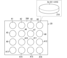
- FIG. 3 is a schematic diagram of a gas sensor in the detector.
- FIG. 4 is a graph showing an example of a model of the change in output over time in one detector.
- FIG. 5 is a graph showing an example of a model of the change over time in output from multiple detectors.
- FIG. 6 is a schematic diagram of a second embodiment of the present disclosure.
- the present disclosure provides a detection system that is less likely to lose detection accuracy when detecting substances that have volatilized from a detection target, and that can increase detection efficiency when substances that have volatilized from multiple detection targets are detected in sequence.
- the detection system 1 includes a plurality of detection units 2 and a switching mechanism 3.
- Each of the plurality of detection units 2 includes a detector 4 that detects at least one substance contained in the gas phase, a detection path 5 through which a gas containing a substance volatilized from a detection target 9 (hereinafter also referred to as a detection gas) flows, and a cleaning path 6 through which a gas not containing a substance volatilized from a detection target 9 (hereinafter also referred to as a cleaning gas) flows.
- the switching mechanism 3 switches the operating state of each of the plurality of detection units 2 between a plurality of states.
- the plurality of states include a first state in which the inflow of the detection gas from the detection path 5 to the detector 4 is permitted, and a second state in which the inflow of the detection gas from the detection path 5 to the detector 4 is not permitted, and the inflow of the cleaning gas from the cleaning path 6 to the detector 4 is permitted.
- substances can be detected while switching the operating state of each of the multiple detection units 2 between multiple states including a first state and a second state.
- each of the multiple detection units 2 can detect substances volatilized from the detection target 9 in the first state, and the detector 4 can be cleaned in the second state. Therefore, when detecting substances volatilized from the detection target 9, the detection accuracy is unlikely to decrease even if substances volatilized from multiple detection targets 9 are detected sequentially.
- the detection system 1 has one inlet 7.
- the start ends of the detection paths 5 in the multiple detection units 2 all lead to the inlet 7.
- the detection system 1 also includes a placement mechanism 8.
- the placement mechanism 8 sequentially places the multiple detection targets 9 one by one at a position facing the inlet 7.
- the placement mechanism 8 includes a mechanism for sequentially moving the multiple detection targets 9 on a path that passes through the position facing the inlet 7.
- the switching mechanism 3 sequentially switches the operating states of the multiple detection units 2 to the first state at staggered times. Furthermore, the switching mechanism 3 synchronizes the switching of the operating state with the placement of the detection target 9 by the placement mechanism 8.
- the switching mechanism 3 includes a detector 31 that detects the presence or absence of the detection target 9 at a specific position on the path along which the multiple detection targets 9 move, and a control unit 32 that controls the timing of switching the operating state based on the detection result by the detector 31.
- the switching mechanism 3 further includes a three-way valve 33.
- the detection system 1 includes five detection units 2.
- Each of the five detection units 2 includes a detector 4, a detection path 5, and a cleaning path 6.
- Each of the five detection units 2 further includes an outlet path 12 and an introduction path 14.
- Each of the detection path 5, the cleaning path 6, the outlet path 12, and the introduction path 14 is composed of, for example, a pipe.
- the detector 4 There are no particular limitations on the detector 4, so long as it outputs a detection result that corresponds to at least one substance in the gas phase. There are no limitations on the form of the detection result, so long as it is a result that depends on the substance.
- the detection result may be a numerical value, or may be a pattern such as a waveform.
- the detector 4 includes, for example, a gas sensor 20.
- the detection result is, for example, a signal output by the gas sensor 20 when at least one substance in the gas phase is supplied to the gas sensor 20, or information obtained by converting this signal.
- the gas sensor 20 includes, for example, a sensor element Ax whose electrical resistance value changes upon adsorbing a substance.
- the gas sensor 20 may be a sensor array including a plurality of sensor elements Ax having different sensing characteristics.
- the detection result is, for example, a collection of signals output by the plurality of sensor elements Ax, or information obtained by converting these signals. In this way, when the gas sensor 20 is a sensor array, various evaluations based on the detection result can be made from a combination of multiple pieces of information.
- the multiple sensor elements Ax having different sensitivity characteristics means that the multiple sensor elements Ax differ from each other in at least one of the substances they can detect and their detection sensitivity to substances. Furthermore, each of the multiple sensor elements Ax may be sensitive to only one type of substance, or may be sensitive to two or more types of substances.
- This detector 4 includes a sensor storage chamber 100, a gas sensor 20, a temperature control element 30, and a temperature sensor 40.
- the gas sensor 20, the temperature control element 30, and the temperature sensor 40 are housed in a storage space 110 inside the sensor storage chamber 100.
- the sensor storage chamber 100 is connected to an outlet path 12 and an inlet path 14.
- the temperature control element 30 is an element that heats the gas sensor 20, and is, for example, an electric heating element 310 that generates heat when electricity is applied.
- the gas sensor 20 is disposed on the electric heating element 310.
- the temperature sensor 40 is, for example, a thermistor, and is disposed near the gas sensor 20 inside the storage space 110.
- the temperature sensor 40 is a sensor for detecting the temperature of the gas sensor 20, and can indirectly detect the temperature of the gas sensor 20, for example, by detecting the temperature around the gas sensor 20 (the temperature of the storage space).
- the temperature control element 30 is controlled by the control unit 32, as described below.
- the gas sensor 20 is a sensor array including multiple sensor elements Ax with different sensing characteristics.
- the gas sensor 20 includes 16 sensor elements Ax.
- the 16 sensor elements Ax may be referred to as sensor elements A1 to A16 (see FIG. 3).
- the 16 sensor elements A1 to A16 are arranged in 4 rows and 4 columns on the substrate 200.
- the number of sensor elements Ax can be changed as appropriate. There is no restriction on how the multiple sensor elements Ax may be arranged, and the multiple sensing elements may be arranged in a line, or may be arranged at intervals on one or more concentric circles.
- Each of the multiple sensor elements Ax includes, for example, a matrix containing an organic material and conductive particles dispersed in the matrix.
- Each sensor element Ax shown in FIG. 3 is a film having a circular shape in a plan view, but the shape of each sensor element Ax is not limited to this.
- the organic material a material having the property of adsorbing at least one substance in the gas phase is selected.
- the organic material contains, for example, at least one selected from the group consisting of chromatographic column packing materials OV-17, OV-22, OV-25, OV-225, OV-330, SILAR-5CP, SILAR-7CP, and OV-275 manufactured by Shinwa Kako Co., Ltd., as well as polystyrene, poly(4-tert-butylstyrene), poly(isobutyl methacrylate), poly(butyl methacrylate), polyvinyl formal, poly(ethylene succinate), low molecular weight poly(vinylidene fluoride), and high molecular weight poly(vinylidene fluoride).
- the multiple sensor elements Ax can have different sensing characteristics.
- the organic materials are not limited to those mentioned above.
- the conductive particles include at least one material selected from the group consisting of, for example, carbon materials, conductive polymers, metals, metal oxides, semiconductors, superconductors, and complex compounds.
- each sensor element Ax When the organic material in each sensor element Ax adsorbs a substance, the volume of the matrix increases, and the distance between the conductive particles in each sensor element Ax increases. Accordingly, the electrical resistance value of each sensor element Ax increases. The greater the amount of marker component that adsorbs to the organic material, the greater the electrical resistance value of each sensor element Ax. Therefore, the change in the electrical resistance value of each sensor element Ax is information that depends on the amount of substance in the gas phase.
- the substrate 200 has electrodes connected to each sensor element Ax.
- a voltage is applied from the electrodes to the sensor element Ax, a current flows through each sensor element Ax according to its own electrical resistance value. This current according to the electrical resistance value, or information obtained by converting this current, is obtained as the output of each sensor element Ax.
- the collection of outputs from the sensor elements Ax is the detection result by the sensor device.
- the detection system 1 further includes a control module 50.
- the control module 50 includes a processing unit 500, a control unit 32, a memory unit 520, and a display unit 570.
- the processing unit 500 is a control circuit that controls the operation of the detector 4.
- the control unit 32 belongs to the switching mechanism 3 and is a control circuit that controls the operation of the switching mechanism 3.
- the processing unit 500 includes an acquisition unit 530, a learning unit 540, and an output unit 560 in addition to a determination unit 550.
- the acquisition unit 530, the learning unit 540, the determination unit 550, and the output unit 560 do not represent physical configurations, but rather represent functions realized by the processing unit 500.
- the acquisition unit 530 acquires the detection results output by the detector 4.
- the learning unit 540 generates a trained model by having an artificial intelligence program (algorithm) machine-learn the training data, and stores this trained model in the memory unit 520.
- the learning unit 540 is responsible for the learning phase of storing combinations of the detection results and judgment results by the detector 4 as training data in the memory unit 520, and creating a trained model MD1 from this training data.
- the learning unit 540 may improve the performance of the trained model MD1 by re-learning using training data newly collected by the acquisition unit 530 after the generation of the trained model MD1.
- the determination unit 550 uses the trained model MD1 stored in the memory unit 520 to make various determinations based on the detection results.
- the output unit 560 outputs the determination result by the determination unit 550 to the display unit 570.
- the memory unit 520 includes one or more storage devices.
- the storage devices are, for example, RAM, ROM, or EEPROM.
- the memory unit 520 stores the trained model MD1 described above, etc.
- the trained model MD1 may be generated by a learning phase using the detector 4 as described above, but may also be generated by a learning system other than the detector 4. If the trained model MD1 is generated by the learning system of the detector 4, the detector 4 does not need to be equipped with a learning unit 540.
- the display unit 570 displays the determination result output by the output unit 560 to the outside in a manner that can be recognized by humans.
- the display unit 570 is, for example, a device that visually displays the determination result, and in that case, the display unit 570 includes a display device such as a liquid crystal display.
- the display unit 570 may be a device that displays the determination result audibly, and in that case, the display unit 570 includes, for example, a buzzer or a speaker.
- judgment result there are no limitations on the content of the judgment result, but it may be, for example, a judgment result on the state, quality, etc. of the detection target 9 depending on the type of detection target 9, etc.
- Each of the processing unit 500 and the control unit 32 may be realized by, for example, a computer system including one or more processors (microprocessors) and one or more memories.
- the one or more processors execute one or more programs (applications) stored in one or more memories to function as the processing unit 500 or the control unit 32.
- the programs are pre-recorded in the memory or storage unit 520 of each of the processing unit 500 and the control unit 32 here, but may be provided via a telecommunications line such as the Internet, or recorded in a non-transient recording medium such as a memory card.
- the processing unit 500 and the control unit 32 include a computer system.
- the computer system is mainly composed of a processor and a memory as hardware.
- the function of the detection system 1 in the present disclosure is realized by the processor executing the program recorded in the memory of the computer system.
- the program may be pre-recorded in the memory of the computer system (such as the storage unit 520), may be provided via a telecommunications line, or may be provided by recording in a non-transient recording medium such as a memory card, an optical disk, or a hard disk drive that can be read by the computer system.
- the processor of the computer system is composed of one or more electronic circuits including a semiconductor integrated circuit (IC) or a large-scale integrated circuit (LSI).
- the IC or LSI as used here refers to an integrated circuit that is called a system LSI, a VLSI (Very Large Scale Integration), or an ULSI (Ultra Large Scale Integration).
- a field-programmable gate array (FPGA) that is programmed after the LSI is manufactured, or a logic device that allows the reconfiguration of the connection relationship within the LSI or the reconfiguration of the circuit partition within the LSI, can also be used as a processor.
- the multiple electronic circuits may be integrated into one chip or distributed among multiple chips.
- the multiple chips may be integrated into one device or distributed among multiple devices.
- the computer system as used here includes a microcontroller having one or more processors and one or more memories. Therefore, the microcontroller is also composed of one or more electronic circuits including a semiconductor integrated circuit or a large-scale integrated circuit.
- control module 50 it is not essential that the multiple functions of the control module 50 are concentrated in one housing, and the components of the control module 50 may be distributed across multiple housings. Furthermore, at least some of the functions of the detector 4 may be realized by the cloud (cloud computing) or the like.
- the sensor storage chamber 100 in the detector 4 is connected to the start of the discharge path 12 and the end of the introduction path 14. This allows gas flowing through the introduction path 14 to be supplied to the detection unit 2, and gas within the detection unit 2 can be discharged through the discharge path 12.
- the start of the introduction path 14 is connected to the end of the detection path 5 and the end of the cleaning path 6.
- the beginning of the cleaning path 6 is connected to a cleaning gas supply source.
- a cleaning gas supply source There are no particular limitations on the cleaning gas, so long as it can be used to clean the detector 4.
- the cleaning gas is, for example, clean air.
- the source of the cleaning gas is, for example, outside air or a gas cylinder.
- the ends of the five detection paths 5 join together and are connected to a single inlet 7.
- the detection system 1 further includes a pump 11 and an exhaust path 13 connected to the pump 11.
- the ends of the outlet paths 12 in the five detection units 2 are all connected to the pump 11.
- the pump 11 can operate to suck in gas in the detector 4 through the outlet path 12 and exhaust it from the exhaust path 13.
- the placement mechanism 8 in the first embodiment is a conveyor that continuously transports multiple detection targets 9, thereby moving the detection targets 9 relative to the inlet 7.
- the conveyor passes below the inlet 7. This allows the placement mechanism 8 to sequentially move the multiple detection targets 9 on a path that passes through a position facing the inlet 7.
- the switching mechanism 3 includes a detector 31, a control unit 32, and a three-way valve 33.
- the three-way valve 33 is provided in each of the five detection units 2.
- the three-way valve 33 is provided at the intersection of the end of the detection path 5, the end of the cleaning path 6, and the beginning of the introduction path 14. That is, the end of the detection path 5 and the end of the cleaning path 6 are connected to the beginning of the introduction path 14 via the three-way valve 33.
- the three-way valve 33 can be switched between a state in which the end of the detection path 5 is connected to the beginning of the introduction path 14 and the end of the cleaning path 6 is not connected to the beginning of the introduction path 14 (hereinafter also referred to as the detection state), and a state in which the end of the detection path 5 is not connected to the beginning of the introduction path 14 and the end of the cleaning path 6 is connected to the beginning of the introduction path 14 (hereinafter also referred to as the cleaning state).
- the detection state of the three-way valve 33 corresponds to the first state of the detection unit 2
- the cleaning state of the three-way valve 33 corresponds to the second state of the detection unit 2.
- the detector 31 is an optical sensor such as a photoelectric sensor, a fiber sensor, a laser sensor, or an image sensor.
- the detector 31 detects the presence or absence of the detection target 9 at a specific position on the path along which the detection target 9 moves, which is opposite the direction of movement of the detection target 9 relative to the position facing the inlet 7, as moved by the positioning mechanism 8. Therefore, the detection result of the detection target 9 by the detector 31 makes it possible to confirm the time when the detection target 9 is positioned opposite the inlet 7.
- control unit 32 is a control circuit included in the control module 50 that controls the switching mechanism 3.
- the detection results from the detector 31 are input to the control unit 32, which controls the three-way valve 33 based on these detection results.
- control unit 32 first controls each three-way valve 33 in the multiple detection units 2 so that all of the three-way valves 33 are in the cleaning state.
- the switching mechanism 3 causes all of the multiple detection units 2 to be in the second state.
- the control unit 32 switches the three-way valve 33 in one of the multiple detection units 2 to the detection state when a certain time has elapsed from that point, and switches it to the cleaning state when a certain time has elapsed again. That is, the switching mechanism 3 switches the operating state of one of the multiple detection units 2 from the second state to the first state when a certain time has elapsed from the point when the detector 31 detects the detection target 9, and then switches it from the first state to the second state when a certain time has elapsed.
- the timing of this switching of the operating state is set so that the detection target 9 detected by the detector 31 is positioned opposite the inlet 7 by the positioning mechanism 8 during the period from when the operating state of the detection unit 2 switches to the first state to when it switches to the second state.
- the control unit 32 similarly switches the operation of the three-way valve 33 of a detection unit 2 other than the previous one.
- the switching mechanism 3 similarly switches the operation state of a detection unit 2 other than the detection unit 2 whose operation state was switched last time.
- the switching mechanism 3 switches the operating state of the multiple detection units 2 in sequence each time the detector 31 detects the detection target 9. In this way, the switching mechanism 3 causes the multiple detection units 2 to sequentially perform a series of operation switches in which the operating state switches from the second state to the first state and then back to the second state.
- the control unit 32 heats the gas sensor 20 for a certain time by passing a current through the electric heating element 310.
- the temperature control unit 510 controls the temperature control element 30 based on the detection result of the temperature sensor 40 so that the temperature of the gas sensor 20 rises to a predetermined temperature.
- the predetermined temperature depends on the type of organic material contained in each sensor element Ax, but is, for example, 60°C or higher and 110°C or lower.
- the time for which the gas sensor 20 is heated is the time during which the detection unit 2 is in the second state or a shorter time.
- the pump 11 and the positioning mechanism 8 are activated when the detection system 1 starts operating.
- the operating states of the multiple detection units 2 at the start of operation are all in the second state.
- the switching mechanism 3 sequentially switches the operating state of each of the multiple detection units 2, and the processing unit 500 processes the detection results output from the detector 4 in each of the multiple detection units 2. This allows the processing unit 500 to obtain detection results based on substances that have volatilized from the detection target 9, or to further perform judgments based on these detection results.
- the operating state of the detection unit 2 when the detection system 1 starts operating is the second state.
- the pump 11 causes gas to flow through the gas path in the detection unit 2.
- the three-way valve 33 is in a cleaning state, so that cleaning gas flows sequentially through the cleaning path 6 and the introduction path 14 and flows into the sensor storage chamber 100 of the detector 4, and the flow of gas from the detection path 5 to the detector 4 is blocked.
- the control unit 32 switches the three-way valve 33 from the cleaning state to the detection state when a certain time has elapsed since the point of detection by the detector 31. This causes the switching mechanism 3 to switch the operating state of the detection unit 2 from the second state to the first state.
- the pump 11 causes gas to flow through the gas path in the detection unit 2.
- detection gas containing substances volatilized from the detection target 9 flows from the inlet 7 into the detection path 5.
- the detection gas flows sequentially through the detection path 5 and the introduction path 14, and flows into the sensor storage chamber 100 of the detector 4, and the flow of gas (cleaning gas) from the cleaning path 6 to the detector 4 is blocked.
- the sensor element Ax is exposed to the detection gas, and substances in the detection gas that volatilize from the detection target 9 are adsorbed to the sensor element Ax. This increases the value of the signal output by the sensor element Ax.
- the detector 4 outputs information about the signal output by the sensor element Ax as the detection result.
- the control unit 32 switches the three-way valve 33 from the detection state to the cleaning state.
- the switching mechanism 3 switches the operating state of the detection unit 2 from the first state to the second state.
- the control unit 32 heats the gas sensor 20 for a certain time by passing a current through the electric heating element 310 based on the detection result of the temperature sensor 40. Then, the cleaning gas flows sequentially through the cleaning path 6 and the introduction path 14 and flows into the sensor storage chamber 100 of the detector 4, and the flow of gas from the detection path 5 to the detector 4 is blocked.
- the detection gas around the gas sensor 20 in the sensor storage chamber 100 of the detector 4 is swept away by the cleaning gas, flows out of the sensor storage chamber 100 into the lead-out path 12, and is further discharged through the discharge path 13.
- a substance is desorbed from the sensor element Ax of the gas sensor 20, and this substance is also discharged.
- Heating the gas sensor 20 promotes the desorption of substances from the sensor element Ax. This attenuates the value of the signal output by the sensor element Ax. This cleans the detector 4, enabling accurate detection the next time a substance volatilized from the detection target 9 is detected.
- FIG. 4 shows a model of the relationship between the output of the detector 4 in one detection unit 2 and the elapsed time when the detection unit 2 operates as described above.
- the detection result output by the detector 4 in the first embodiment is actually a collection of signals output by multiple sensor elements Ax, or information obtained by converting these signals.
- the magnitude of the degree of change in the physical property value sensitive to the substance of the entire multiple sensor elements Ax is considered to be the output of the detector 4.
- the detection gas in the first state, the detection gas is supplied to the detector 4, and the output increases, and then in the second state, the cleaning gas is supplied to the detector 4, the detector 4 is cleaned, and the output attenuates.
- the detection unit 2 operates in this manner, accurate detection of the substance is possible by repeating the detection of the substance by the detection unit 2 and the cleaning of the detection unit 2.
- the flow of gas from the detection path 5 to the detector 4 is blocked, so the output of the detector 4 attenuates without being affected by substances volatilized from another detection target 9, which also enables accurate detection of substances.
- the detection unit 2 cannot detect substances, and there are periods during which the detection unit 2 cannot detect substances.
- the detection system 1 operates as described above, and the switching mechanism 3 sequentially switches the operating states of the multiple detection units 2 at staggered times.
- the positioning mechanism 8 sequentially positions the multiple detection targets 9 one by one at a position facing the inlet 7, and the switching mechanism 3 synchronizes the switching of the operating states of the detection units 2 with the positioning of the detection targets 9 by the positioning mechanism 8. Therefore, while one detection unit 2 is in the second state and the detector 4 of this detection unit 2 is being cleaned, the remaining detection units 2 sequentially detect substances.
- Figure 5 shows a model in which the relationship between the output of the detector 4 and the elapsed time in multiple detection units 2 is displayed in an overlapping manner.
- the magnitude of the change in the physical property value in response to the substance for the entire multiple sensor elements Ax is considered to be the output of the detector 4.
- the substance can be detected sequentially in multiple detection units 2. Therefore, when detecting a substance volatilizing from multiple detection targets 9 sequentially, although there will be periods when the substance cannot be detected in each detection unit 2, the detection can be performed by sequentially using multiple detection units 2, and therefore the detection efficiency can be improved.
- the detection result output by the detector 4 is acquired by the processing unit 500 as described above, or a judgment or the like is made based on this detection result.
- the detection result can include not only the increased output of the detector 4 in the first state, but also the attenuated output of the detector 4 in the second state.
- the output of the detector 4 in the second state attenuates without being affected by the substance volatilized from another detection target 9, so the manner in which the output attenuates depends heavily on the substance volatilized from the detection target 9. Therefore, if the detection result includes the attenuation of the output in the second state, the detection result can be used for a wider variety of judgments, etc.
- the detection system 1 has multiple inlets 7.
- the number of inlets 7 is the same as the number of detection units 2.
- the start ends of the detection paths 5 in the multiple detection units 2 each lead to one of the multiple inlets 7.
- the detection system 1 also includes a placement mechanism 8.
- the placement mechanism 8 sequentially places the multiple detection targets 9 one by one at a position facing each of the multiple inlets 7.
- the placement mechanism 8 includes a mechanism for sequentially moving the multiple detection targets 9 on a path that sequentially passes through the positions facing the multiple inlets 7.
- the switching mechanism 3 simultaneously switches the operating states of the multiple detection units 2 to the first state. Furthermore, the switching mechanism 3 synchronizes the switching of the operating state with the placement of the detection target 9 by the placement mechanism 8.
- the switching mechanism 3 includes a detector 31 that detects the presence or absence of the detection target 9 at a specific position on the path along which the multiple detection targets 9 move, and a control unit 32 that controls the timing of switching the operating state based on the detection result by the detector 31.
- the switching mechanism 3 further includes a three-way valve 33.
- the detection system 1 includes five detection units 2. Each of the five detection units 2 includes a detector 4, a detection path 5, and a cleaning path 6. Each of the five detection units 2 further includes an outlet path 12 and an introduction path 14.
- the detection system 1 further includes a control module 50.
- the control module 50 includes a processing unit 500, a control unit 32, a memory unit 520, and a display unit 570.
- the detection system 1 has five inlets 7, the same number as the detection units 2. The ends of the five detection paths 5 are connected to the five inlets 7, respectively. The five inlets 7 are arranged at intervals.
- the detection system 1 further includes a pump 11 and an exhaust path 13 connected to the pump 11.
- the ends of the outlet paths 12 in the five detection units 2 are all connected to the pump 11.
- the pump 11 can operate to suck in gas in the detector 4 through the outlet path 12 and exhaust it from the exhaust path 13.
- the placement mechanism 8 in the second embodiment is a conveyor that continuously transports the multiple detection targets 9, thereby moving the detection targets 9 relative to the inlet 7.
- the conveyor passes through positions below the multiple inlets 7 in sequence. This allows the placement mechanism 8 to move the multiple detection targets 9 in sequence on a path that passes through positions facing the multiple inlets 7 in sequence.
- the switching mechanism 3 includes a detector 31, a control unit 32, and a three-way valve 33.
- the detector 31 in the second embodiment detects the presence or absence of the detection target 9 at a specific position on the path along which the detection target 9 moves, for example, as moved by the positioning mechanism 8, which is opposite the direction of movement of the detection target 9 rather than a position facing any of the inlets 7. Therefore, the detection result of the detection target 9 by the detector 31 makes it possible to confirm the time when the detection target 9 is positioned opposite one of the inlets 7.
- the detection results from the detector 31 are input to the control unit 32, which controls the three-way valve 33 based on these detection results.
- control unit 32 first controls each three-way valve 33 in the multiple detection units 2 so that all of the three-way valves 33 are in the cleaning state.
- the switching mechanism 3 causes all of the multiple detection units 2 to be in the second state.
- the control unit 32 simultaneously switches the three-way valves 33 in all of the multiple detection units 2 to the detection state when a certain time has elapsed from that point, and then simultaneously switches them to the cleaning state when a certain time has elapsed. That is, the switching mechanism 3 simultaneously switches the operating state of all of the multiple detection units 2 from the second state to the first state when a certain time has elapsed from the point when the detector 31 detects the detection target 9, and then simultaneously switches them from the first state to the second state when a certain time has elapsed.
- the timing of this switching of the operating state is set so that the detection target 9 detected by the detector 31 is positioned by the positioning mechanism 8 to face any specific inlet 7 (for example, the inlet 7 of the multiple inlets 7 that is positioned closest to the direction of movement of the detection target 9).
- the switching mechanism 3 repeats the above operation each time the detector 31 detects the detection target 9 the same number of times as the number of detection units 2 (i.e., five times). As a result, the operating states of the multiple detection units 2 are simultaneously switched each time the detector 31 detects the detection target 9 the same number of times as the number of detection units 2. As a result, the switching mechanism 3 causes the multiple detection units 2 to simultaneously perform a series of operation switches, in which the operating state switches from the second state to the first state and then back to the second state.
- the control unit 32 heats the gas sensor 20 for a certain period of time by passing a current through the electric heating element 310, in the same manner as in the first embodiment.
- the gas sensor 20 is heated and its temperature increases, if a substance is adsorbed to the sensor element Ax, desorption of the substance from the sensor element Ax is promoted.
- the pump 11 and the arrangement mechanism 8 are activated when the detection system 1 starts operating.
- the arrangement mechanism 8 transports multiple detection targets 9 in a line with a space between them.
- the space between the detection targets 9 is set to match the space between the inlets 7.
- the operating states of the multiple detection units 2 at the start of operation are all in the second state.
- the switching mechanism 3 simultaneously switches the operating states of the multiple detection units 2, and the processing unit 500 processes the detection results output from the detector 4 in each of the multiple detection units 2. This allows the processing unit 500 to obtain detection results based on substances that have volatilized from the detection targets 9, or to further perform judgments based on these detection results.
- the individual operations of the multiple detection units 2 are the same as in the first embodiment (see FIG. 4). Therefore, in the second embodiment, too, in the second state, the detection units 2 cannot detect a substance, and there is a period during which the detection units 2 cannot detect a substance.
- the operating state of all of the multiple detection units 2 is switched to the first state. Therefore, substances volatilizing from the multiple detection units 2 are detected simultaneously.
- the switching mechanism 3 switches the operating state of all of the multiple detection units 2 to the second state simultaneously through the above-mentioned operation, and cleans all of the detectors 4 simultaneously.
- the positioning mechanism 8 moves the multiple detection targets 9 relative to the inlet 7, so that the same number of detection targets 9 as the detection units 2 that were the detection targets are positioned opposite the multiple inlets 7, followed by another number of detection targets 9 as the detection units 2.
- the operating state of all of the multiple detection units 2 has been switched back to the first state. As a result, substances volatilizing from the multiple detection units 2 are detected simultaneously.
- substance detection can be performed simultaneously in multiple detection units 2. Therefore, when detecting a substance volatilizing from multiple detection targets 9, periods in which the substance cannot be detected by multiple detection units 2 simultaneously occur, but the detection can be performed using multiple detection units 2, which can increase the efficiency of detection.
- the detection results output by the detector 4 are also acquired by the processing unit 500, or a determination is made based on the detection results.
- the detection state of the three-way valve 33 may be a state in which the end of the detection path 5 is connected to the start of the introduction path 14, and the end of the cleaning path 6 is also connected to the start of the introduction path 14.
- the switching mechanism 3 includes a three-way valve 33, and the operating state of the detection unit 2 is switched between a first state and a second state by switching the three-way valve 33 between a detection state and a cleaning state, but the aspect of the switching mechanism 3 is not limited to this.
- the switching mechanism 3 may include an on-off valve that opens and closes the flow of gas in the detection path 5 and an on-off valve that opens and closes the flow of gas in the cleaning path 6, and the first state and the second state may be realized by opening and closing these on-off valves.
- the operating state of the detection unit 2 includes the first state and the second state, but may further include other states.
- the operating state of the detection unit 2 may include a third state in which the flow of detection gas from the detection path 5 to the detector 4 is not permitted, and the flow of detection gas from the cleaning path 6 to the detector 4 is also not permitted.
- the operating state when the operating state switches from the first state to the second state, the operating state may first switch from the first state to the third state, and then switch to the second state.
- the operating state may first switch from the second state to the third state, and then switch to the first state.
- the operating state may include states other than the first state, the second state, and the third state.
- the switching mechanism 3 includes a detector 31, and the detection results of this detector 31 are used to synchronize the switching of the operating state of the detection unit 2 with the placement of the detection target 9 by the placement mechanism 8; however, the switching mechanism 3 does not need to include a detector 31.
- the switching mechanism 3 may also synchronize the switching of the operating state with the placement of the detection target 9 by the placement mechanism 8 by means other than using the detector 31.
- the switching of the operating state may be synchronized with the placement of the detection target 9 by the placement mechanism 8 by switching the operating state of the detection unit 2 at regular intervals while moving multiple detection targets 9 at a constant speed, without detecting the positions of the detection targets 9.
- the arrangement mechanism 8 includes a conveyor that transports the detection targets 9, but the arrangement mechanism 8 is not limited to this. There are no limitations on the configuration of the arrangement mechanism 8 as long as it moves the multiple detection targets 9 relative to the inlet 7.
- the arrangement mechanism 8 may also move the detection targets 9 relative to the inlet 7 by moving the position of the inlet 7 without moving the position of the detection targets 9.
- the structure of the arrangement mechanism 8 is not limited to a structure that moves the multiple detection targets 9 only in one direction relative to the inlet 7, but may be a structure that can move the detection targets 9 in two axial directions relative to the inlet 7, such as a two-axis stage. In this case, the multiple detection targets 9 may be arranged in a matrix of multiple rows and columns, rather than in a single row.
- the configuration of the detector 4 is not limited to the first and second embodiments.
- the configuration of the gas sensor is not limited to the above, and when a substance is adsorbed, bound, trapped, or interacted with an appropriate gas sensor, the weight, electrical characteristics (electrical resistance, dielectric constant, etc.), resonant frequency, intensity or change in the amount of emitted light, or amount of emitted radiation, etc. of the gas sensor may be obtained as the detection result.
- the detector 4 may be a means for quantifying a substance by measuring the absorbance of the substance in the gas phase.
- the detector 4 includes a temperature control element 30 that heats the gas sensor 20, and in the second state the gas sensor 20 is heated by the temperature control element 30, but the gas sensor 20 does not have to be heated in the second state, and therefore the detector 4 does not have to include the temperature control element 30. Even if the gas sensor 20 is not heated in the second state, the detector 4 can be cleaned if a cleaning gas is supplied to the detector 4 without supplying a detection gas to the detector 4 in the second state.
- the detection target 9 may be any object.
- the detection target 9 may be an industrial product, a drug, a specimen, a processed food, a fresh food, or a plant.
- substances volatilizing from the detection target 9 may be detected for the purpose of quality control, analysis, diagnosis, or any other type of judgment or evaluation.
- the detection system (1) includes a plurality of detection units (2) and a switching mechanism (3).
- Each of the plurality of detection units (2) includes a detector (4) for detecting at least one substance contained in a gas phase, a detection path (5) through which a gas containing a substance volatilized from a detection target (9) flows, and a cleaning path (6) through which a gas not containing a substance volatilized from the detection target (9) flows.
- the switching mechanism (3) switches the operating state of each of the plurality of detection units (2) between a plurality of states.
- the plurality of states include a first state in which gas is permitted to flow from the detection path (5) to the detector (4), and a second state in which gas is not permitted to flow from the detection path (5) to the detector (4) and gas is permitted to flow from the cleaning path (6) to the detector (4).
- the switching mechanism (3) alternately switches the operating state of each of the multiple detection units (2) between a first state and a second state.
- the detection system (1) in the first or second aspect further includes an inlet (7), and the start ends of the detection paths (5) in the multiple detection sections (2) all lead to the inlet (7).
- the substance volatilized from the detection target (9) is sent from the inlet (7) through the detection path (5) to the detector (4), where it can be detected.
- the switching mechanism (3) switches the operating states of the multiple detection units (2) to the first state sequentially at staggered times.
- substances volatilized from multiple detection targets (9) can be detected sequentially by the detectors (4) of multiple detection units (2).
- the detection system (1) in the fourth aspect further includes a positioning mechanism (8) that sequentially positions a plurality of detection targets (9) one by one at a position facing the inlet (7).
- the switching mechanism (3) synchronizes the switching of the operating state with the positioning of the detection targets (9) by the positioning mechanism (8).
- the positioning mechanism (8) includes a mechanism for sequentially moving a plurality of detection targets (9) on a path that passes through a position facing the inlet (7).
- the switching mechanism (3) includes a detector (31) that detects the presence or absence of a detection target (9) at a specific position on the path, and a control unit (32) that controls the timing of switching the operating state based on the detection result by the detector (31).
- the switching mechanism (3) can accurately synchronize the switching of the operating state with the placement of the detection target (9) by the placement mechanism (8) by using the detection results by the detector (31).
- the detection system (1) in the first or second aspect further includes a plurality of inlets (7), and the start ends of the detection paths (5) of the plurality of detection units (2) are each connected to the plurality of inlets (7).
- substances volatilized from multiple detection targets (9) can be sent from multiple inlets (7) through detection paths (5) to the detector (4) and detected, thereby improving detection efficiency.
- the switching mechanism (3) simultaneously switches the operating state of the multiple detection units (2) to the first state.
- substances volatilized from multiple detection targets (9) can be simultaneously detected by multiple detection units (2).
- the detection system (1) of the eighth aspect further includes a positioning mechanism (8) that sequentially positions a plurality of detection targets (9) one by one at positions facing each of the plurality of inlets (7), and the switching mechanism (3) synchronizes the switching of the operating state with the positioning of the detection targets (9) by the positioning mechanism (8).
- the positioning mechanism (8) includes a mechanism for sequentially moving a plurality of detection targets (9) on a path that sequentially passes through positions facing a plurality of inlets (7).
- the switching mechanism (3) includes a detector (31) that detects the presence or absence of a detection target (9) at a specific position on the path, and a control unit (32) that controls the timing of switching the operating state based on the detection result by the detector (31).
- the switching mechanism (3) can accurately synchronize the switching of the operating state with the placement of the detection target (9) by the placement mechanism (8) by using the detection results by the detector (31).
- the detector (4) is provided with a sensor element (Ax) whose electrical resistance value changes upon adsorbing a substance.
- the detector (4) is provided with a sensor array including a plurality of sensor elements (Ax) having different sensing characteristics.
- the detection method is a detection method for detecting a substance volatilized from a detection target (9) using a detection system (1).
- the detection system (1) includes a plurality of detection units (2).
- Each of the plurality of detection units (2) includes a detector (4) for detecting at least one substance contained in a gas phase, a detection path (5) through which a gas containing the substance volatilized from the detection target (9) flows, and a cleaning path (6) through which a gas not containing the substance volatilized from the detection target (9) flows.
- the detection method includes switching the operating state of each of the plurality of detection units (2) between a plurality of states.
- the plurality of states include a first state in which gas is permitted to flow from the detection path (5) to the detector (4), and a second state in which gas is not permitted to flow from the detection path (5) to the detector (4) and gas is permitted to flow from the cleaning path (6) to the detector (4).
Landscapes
- Physics & Mathematics (AREA)
- Health & Medical Sciences (AREA)
- Life Sciences & Earth Sciences (AREA)
- Chemical & Material Sciences (AREA)
- Analytical Chemistry (AREA)
- Biochemistry (AREA)
- General Health & Medical Sciences (AREA)
- General Physics & Mathematics (AREA)
- Immunology (AREA)
- Pathology (AREA)
- Investigating Or Analyzing Materials By The Use Of Electric Means (AREA)
Priority Applications (1)
| Application Number | Priority Date | Filing Date | Title |
|---|---|---|---|
| JP2024560148A JPWO2024111559A1 (https=) | 2022-11-25 | 2023-11-20 |
Applications Claiming Priority (2)
| Application Number | Priority Date | Filing Date | Title |
|---|---|---|---|
| JP2022-188669 | 2022-11-25 | ||
| JP2022188669 | 2022-11-25 |
Publications (1)
| Publication Number | Publication Date |
|---|---|
| WO2024111559A1 true WO2024111559A1 (ja) | 2024-05-30 |
Family
ID=91196140
Family Applications (1)
| Application Number | Title | Priority Date | Filing Date |
|---|---|---|---|
| PCT/JP2023/041671 Ceased WO2024111559A1 (ja) | 2022-11-25 | 2023-11-20 | 検出システム及び検出方法 |
Country Status (2)
| Country | Link |
|---|---|
| JP (1) | JPWO2024111559A1 (https=) |
| WO (1) | WO2024111559A1 (https=) |
Citations (2)
| Publication number | Priority date | Publication date | Assignee | Title |
|---|---|---|---|---|
| JP2001174373A (ja) * | 1999-12-17 | 2001-06-29 | Shimadzu Corp | におい識別装置 |
| JP2014010119A (ja) * | 2012-07-02 | 2014-01-20 | One A:Kk | 気密性検査装置及び検査対象物の気密性を検査する方法 |
-
2023
- 2023-11-20 WO PCT/JP2023/041671 patent/WO2024111559A1/ja not_active Ceased
- 2023-11-20 JP JP2024560148A patent/JPWO2024111559A1/ja active Pending
Patent Citations (2)
| Publication number | Priority date | Publication date | Assignee | Title |
|---|---|---|---|---|
| JP2001174373A (ja) * | 1999-12-17 | 2001-06-29 | Shimadzu Corp | におい識別装置 |
| JP2014010119A (ja) * | 2012-07-02 | 2014-01-20 | One A:Kk | 気密性検査装置及び検査対象物の気密性を検査する方法 |
Also Published As
| Publication number | Publication date |
|---|---|
| JPWO2024111559A1 (https=) | 2024-05-30 |
Similar Documents
| Publication | Publication Date | Title |
|---|---|---|
| Han et al. | Artificial olfactory neuron for an in‐sensor neuromorphic nose | |
| Hirtzlin et al. | Digital biologically plausible implementation of binarized neural networks with differential hafnium oxide resistive memory arrays | |
| Messaris et al. | A data-driven verilog-a reram model | |
| Attallah et al. | An electronic nose for identifying multiple combustible/harmful gases and their concentration levels via artificial intelligence | |
| JP5840727B2 (ja) | 物体検出に応答して情報を取得する装置 | |
| Betta et al. | Contaminants detection and classification through a customized IoT-based platform: A case study | |
| JP2010522322A (ja) | 発光センサ | |
| EP2502065A2 (en) | A diagnostic apparatus | |
| Song et al. | Reconfigurable and Efficient Implementation of 16 Boolean Logics and Full‐Adder Functions with Memristor Crossbar for Beyond von Neumann In‐Memory Computing | |
| Antolini et al. | Characterization and programming algorithm of phase change memory cells for analog in-memory computing | |
| US20240402143A1 (en) | Gas analyzing method, and gas analyzing system | |
| Bruschi et al. | A novel integrated smart system for indoor air monitoring and gas recognition | |
| Nandakumar et al. | A low-cost electrochemical biosensor for rapid bacterial detection | |
| WO2024111559A1 (ja) | 検出システム及び検出方法 | |
| Yang et al. | An automated point-of-care system for immunodetection of staphylococcal enterotoxin B | |
| Fernandez et al. | Matsa: An mram-based energy-efficient accelerator for time series analysis | |
| Spetalnick et al. | An edge accelerator with 5 mb of 0.256-pj/bit embedded rram and a localization solver for bristle robot surveillance | |
| CN103336026A (zh) | 一种检测气体的聚合物压电气体传感器系统 | |
| EP3791164B1 (en) | Surface plasmon resonance gas detection system | |
| Fay et al. | Optical Measurements Using LED Discharge Photometry (PEDD Approach): Critical Timing Effects Identified & Corrected | |
| UA104233C2 (en) | Intellectual sensor | |
| Fonollosa et al. | Dataset from chemical gas sensor array in turbulent wind tunnel | |
| Vyshniakova et al. | Aqueous Ammonia Sensor with Neuromorphic Detection | |
| CN204255932U (zh) | 一种便携式微量气体检测系统 | |
| WO2002077631A1 (es) | Instrumento y método para el análisis, identificación y cuantificacíon de gases o líquidos |
Legal Events
| Date | Code | Title | Description |
|---|---|---|---|
| 121 | Ep: the epo has been informed by wipo that ep was designated in this application |
Ref document number: 23894565 Country of ref document: EP Kind code of ref document: A1 |
|
| WWE | Wipo information: entry into national phase |
Ref document number: 2024560148 Country of ref document: JP |
|
| NENP | Non-entry into the national phase |
Ref country code: DE |
|
| 122 | Ep: pct application non-entry in european phase |
Ref document number: 23894565 Country of ref document: EP Kind code of ref document: A1 |