WO2024106161A1 - 電解システムおよび電解方法 - Google Patents
電解システムおよび電解方法 Download PDFInfo
- Publication number
- WO2024106161A1 WO2024106161A1 PCT/JP2023/038664 JP2023038664W WO2024106161A1 WO 2024106161 A1 WO2024106161 A1 WO 2024106161A1 JP 2023038664 W JP2023038664 W JP 2023038664W WO 2024106161 A1 WO2024106161 A1 WO 2024106161A1
- Authority
- WO
- WIPO (PCT)
- Prior art keywords
- mediator
- electrolysis
- electrode
- cathode
- cell
- Prior art date
- Legal status (The legal status is an assumption and is not a legal conclusion. Google has not performed a legal analysis and makes no representation as to the accuracy of the status listed.)
- Ceased
Links
Images
Classifications
-
- C—CHEMISTRY; METALLURGY
- C25—ELECTROLYTIC OR ELECTROPHORETIC PROCESSES; APPARATUS THEREFOR
- C25B—ELECTROLYTIC OR ELECTROPHORETIC PROCESSES FOR THE PRODUCTION OF COMPOUNDS OR NON-METALS; APPARATUS THEREFOR
- C25B1/00—Electrolytic production of inorganic compounds or non-metals
- C25B1/50—Processes
-
- C—CHEMISTRY; METALLURGY
- C25—ELECTROLYTIC OR ELECTROPHORETIC PROCESSES; APPARATUS THEREFOR
- C25B—ELECTROLYTIC OR ELECTROPHORETIC PROCESSES FOR THE PRODUCTION OF COMPOUNDS OR NON-METALS; APPARATUS THEREFOR
- C25B1/00—Electrolytic production of inorganic compounds or non-metals
- C25B1/01—Products
- C25B1/02—Hydrogen or oxygen
- C25B1/04—Hydrogen or oxygen by electrolysis of water
-
- C—CHEMISTRY; METALLURGY
- C25—ELECTROLYTIC OR ELECTROPHORETIC PROCESSES; APPARATUS THEREFOR
- C25B—ELECTROLYTIC OR ELECTROPHORETIC PROCESSES FOR THE PRODUCTION OF COMPOUNDS OR NON-METALS; APPARATUS THEREFOR
- C25B3/00—Electrolytic production of organic compounds
- C25B3/01—Products
- C25B3/03—Acyclic or carbocyclic hydrocarbons
-
- C—CHEMISTRY; METALLURGY
- C25—ELECTROLYTIC OR ELECTROPHORETIC PROCESSES; APPARATUS THEREFOR
- C25B—ELECTROLYTIC OR ELECTROPHORETIC PROCESSES FOR THE PRODUCTION OF COMPOUNDS OR NON-METALS; APPARATUS THEREFOR
- C25B3/00—Electrolytic production of organic compounds
- C25B3/20—Processes
- C25B3/25—Reduction
-
- Y—GENERAL TAGGING OF NEW TECHNOLOGICAL DEVELOPMENTS; GENERAL TAGGING OF CROSS-SECTIONAL TECHNOLOGIES SPANNING OVER SEVERAL SECTIONS OF THE IPC; TECHNICAL SUBJECTS COVERED BY FORMER USPC CROSS-REFERENCE ART COLLECTIONS [XRACs] AND DIGESTS
- Y02—TECHNOLOGIES OR APPLICATIONS FOR MITIGATION OR ADAPTATION AGAINST CLIMATE CHANGE
- Y02E—REDUCTION OF GREENHOUSE GAS [GHG] EMISSIONS, RELATED TO ENERGY GENERATION, TRANSMISSION OR DISTRIBUTION
- Y02E60/00—Enabling technologies; Technologies with a potential or indirect contribution to GHG emissions mitigation
- Y02E60/30—Hydrogen technology
- Y02E60/36—Hydrogen production from non-carbon containing sources, e.g. by water electrolysis
Definitions
- the present invention relates to an electrolysis system and an electrolysis method.
- renewable energy sources such as solar, wind, hydroelectric, and geothermal power
- One example is an electrolysis system that uses electricity derived from renewable energy sources to perform water electrolysis to generate hydrogen (see, for example, Patent Document 1).
- organic hydrides are attracting attention as an energy carrier for the large-scale transport and storage of hydrogen derived from renewable energy sources.
- a known technology for producing organic hydrides is an electrolysis system that generates protons from water at the anode electrode and hydrogenates the substance to be hydrided with the protons at the cathode electrode to produce organic hydrides.
- the present invention was made in light of these circumstances, and one of its objectives is to improve the safety of electrolysis systems.
- One aspect of the present invention is an electrolysis system.
- This electrolysis system includes an electrolysis cell and a mediator reduction cell connected to the electrolysis cell.
- the electrolysis cell has an anode electrode that electrochemically oxidizes the reduced form of the mediator, and a cathode electrode that performs at least one of generating hydrogen by electrochemical reduction of protons or water and generating an organic hydride by electrochemical reduction of the substance to be hydrided.
- the mediator reduction cell non-photochemically reduces the oxidized form of the mediator produced in the electrolysis cell.
- Another aspect of the present invention is an electrolysis method using an electrolysis system including an electrolysis cell and a mediator reduction cell connected to the electrolysis cell.
- This electrolysis method includes electrochemically oxidizing a reduced form of the mediator to generate an oxidized form of the mediator at the anode electrode of the electrolysis cell, electrochemically reducing protons or water to generate hydrogen at the cathode electrode of the electrolysis cell, or electrochemically reducing a substance to be hydrided to generate an organic hydride at the cathode electrode of the electrolysis cell, and non-photochemically reducing the oxidized form generated in the electrolysis cell to generate a reduced form in the mediator reduction cell.
- the present invention makes it possible to improve the safety of electrolysis systems.
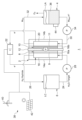
- FIG. 1 is a schematic diagram of an electrolysis system according to an embodiment.
- FIG. 1 is a schematic diagram of an electrolysis system 1 according to an embodiment.
- the electrolysis system 1 includes an electrolysis cell 2, a mediator reduction tank 4, and a cathode liquid tank 6. Although only one electrolysis cell 2 is illustrated in FIG. 1, the electrolysis system 1 may include multiple electrolysis cells 2. In this case, the electrolysis cells 2 are stacked and electrically connected in series, for example, with their cathode electrodes 8 and anode electrodes 10 aligned in the same direction. The electrolysis cells 2 may be connected in parallel, or a combination of serial and parallel connections may be used.
- the configuration of the electrolysis system 1 is not limited to that described below, and the configuration of each part may be changed as appropriate.
- the electrolysis cell 2 has a cathode electrode 8 (negative electrode), an anode electrode 10 (positive electrode), and an electrolyte membrane 12.
- the cathode electrode 8 performs at least one of the following: generating hydrogen by electrochemical reduction of protons or water, and generating organic hydrides by electrochemical reduction of the substance to be hydrided.
- electrochemical means that the reaction proceeds when a voltage is applied from outside the electrolysis cell 2 or when a current is superimposed.
- the cathode electrode 8 has a cathode catalyst 9 that generates at least one of hydrogen and organic hydrides.
- the cathode electrode 8 is provided with a cathode catalyst layer containing the cathode catalyst 9.
- a known catalyst such as platinum (Pt) can be used for the cathode catalyst 9.
- a known catalyst such as platinum or ruthenium (Ru) can be used for the cathode catalyst 9. It is also possible to generate both hydrogen and organic hydrides in one electrolysis cell 2. For example, an operation mode is possible in which hydrogen is generated during the day when hydrogen demand is high, and organic hydrides are generated and hydrogen is stored at night when hydrogen demand is low.
- the cathode catalyst 9 can be supported by a porous catalyst carrier.
- the catalyst carrier is composed of an electron conductive material such as porous carbon, porous metal, or porous metal oxide.
- the cathode catalyst 9 has resistance to deterioration of the mediator, taking into consideration the possibility that the mediator may permeate the electrolyte membrane 12. It is also preferable that the cathode catalyst 9 is difficult to adsorb the mediator. It is also preferable that the cathode catalyst 9 is difficult to precipitate the mediator.
- the cathode catalyst 9 is coated with a cation exchange ionomer.
- the catalyst carrier supporting the cathode catalyst 9 is coated with an ionomer.
- cation exchange ionomers include perfluorosulfonic acid polymers such as Nafion (registered trademark), Flemion (registered trademark), Aquivion (registered trademark), and Aciplex (registered trademark), and hydrocarbon-based sulfonic acid polymers. It is preferable that the ionomer partially coats the cathode catalyst 9. This allows the three elements (product to be hydrided, protons, and electrons) necessary for the electrochemical reaction at the cathode electrode 8 to be efficiently supplied to the reaction field.
- the cathode catalyst 9 is coated with an anion exchange type ionomer.
- the catalyst carrier supporting the cathode catalyst 9 is coated with an ionomer.
- An example of an anion exchange type ionomer is a polymer such as Fumion (registered trademark). It is preferable that the ionomer partially coats the cathode catalyst 9. This allows the three elements (product to be hydrided, water, and electrons) necessary for the electrochemical reaction at the cathode electrode 8 to be efficiently supplied to the reaction field.
- the cathode electrode 8 may be provided with a cathode diffusion layer.
- the cathode catalyst layer is disposed so as to contact one of the main surfaces of the electrolyte membrane 12.
- the cathode diffusion layer is disposed so as to contact the main surface of the cathode catalyst layer opposite the electrolyte membrane 12.
- the cathode diffusion layer is made of a conductive material such as carbon or metal.
- the cathode diffusion layer is also a porous body such as a sintered body of fibers or particles, or a foam molded body. Examples of materials constituting the cathode diffusion layer include woven carbon fabric (carbon cloth), nonwoven carbon fabric, and carbon paper.
- the cathode diffusion layer may be omitted in some cases.
- the anode electrode 10 electrochemically oxidizes the reduced form M Red of the mediator.
- the anode electrode 10 has an anode catalyst 11 that oxidizes the reduced form M Red of the mediator to generate the oxidized form M Ox of the mediator and electrons.
- the anode electrode 10 is provided with an anode catalyst layer including the anode catalyst 11.
- the anode catalyst 11 may be a known porous body having electrical conductivity. Specific examples of the anode catalyst 11 include carbon porous bodies such as carbon paper and carbon felt; metal porous bodies such as metal foam; and a three-dimensional structure composed of a mixture of conductive particles and a binder.
- the anode catalyst 11 may have a structure in which a substance having catalytic action is supported on a porous body that does not have catalytic action or has catalytic action.
- the anode catalyst 11 only needs to have activity in the oxidation reaction of the reductant M Red , and does not need to have activity in the oxygen evolution reaction (OER). For this reason, depending on the mediator used, an inexpensive electrode such as carbon can be used as the anode catalyst 11. It is preferable that the anode catalyst 11 has durability at the redox potential of the mediator.
- the anode catalyst 11 may be one that does not cause an oxidation-reduction reaction in the range of 0 to 2.5 V vs. RHE at the pH of the solution containing the mediator. It is preferable that the anode catalyst 11 does not undergo a phase change in the range of 0.1 to 2.3 V vs. RHE, and more preferably does not undergo a phase change in the range of 0.2 to 2.0 V vs. RHE.
- the mediator is a liquid or solid at room temperature and pressure.
- room temperature and pressure is, for example, 20°C and 1 atmosphere.
- the mediator is a solid at room temperature and pressure, it is preferable to use the mediator in a state dissolved in a solvent such as water, for example, as the anolyte liquid LA described below.
- a solution containing a mediator that is liquid at room temperature and pressure or a solid mediator it is possible to easily supply the mediator to the anode electrode 10. It is also possible to make the mediator react more easily at the anode electrode 10.
- mediators that are gaseous at room temperature and pressure it is possible to increase the types of mediators that can be selected.
- Inorganic materials are mainly ionic salts, and as an example, when dissolved in a solvent, the ions react as a mediator.
- Organic materials react as a mediator themselves.
- Organic materials include organometallic compounds. Inorganic materials tend to be more durable than organic materials. They are particularly stable in oxidizing environments. On the other hand, it is easier to change the structure of organic materials than inorganic materials, so it is easier to adjust physical properties such as electric potential and solubility compared to inorganic materials.
- the mediator does not undergo a phase change in the range of -0.5 to 2.5 V vs. RHE at the pH of the solution containing the mediator, more preferably, does not undergo a phase change in the range of -0.4 to 2.3 V vs. RHE, and even more preferably, does not undergo a phase change in the range of -0.3 to 2.0 V vs. RHE.
- the mediator is composed of a redox couple having an electrode potential more noble than the electrode potential at which oxygen is generated at the anode electrode 10 at the operating temperature of the electrolytic cell 2.
- redox couples include pairs of oxidized and reduced forms of at least one substance selected from the group consisting of silver (Ag), manganese (Mn), cerium (Ce), cobalt (Co), chromium (Cr), halogens, halogen oxoacids, nickel (Ni), peroxodisulfuric acid, thallium (Tl), and selenic acid.
- the redox potential of the mediator can be adjusted by forming an appropriate complex with these substances.
- the mediator can be present in a dissolved or dispersed state in the anolyte LA described below.
- the standard electrode potential for oxygen generation at the anode electrode 10 at the operating temperature of the electrolytic cell 2 can be calculated based on the Nernst equation.
- the electrode potential of the aqueous mediator solution is preferably 1.12 V vs. RHE or higher, and more preferably 1.48 V vs. RHE or higher.
- the theoretical reaction potential in the oxygen generation reaction is 1.12 V vs. RHE at 150°C.
- the thermoneutral potential is 1.48 V vs. RHE.
- “Thermonutral potential” means a potential at which no heat is absorbed or generated during the reaction.
- the oxygen generation reaction will proceed at 150°C or less in the mediator reduction tank 4.
- the electrode potential of the mediator aqueous solution is lower than 1.12 V vs. RHE, the oxygen generation reaction will not proceed spontaneously in the mediator reduction tank 4.
- the electrode potential of the mediator aqueous solution is 1.12 V vs. RHE or higher.
- the electrode potential of the mediator aqueous solution is 1.48 V vs. RHE, which is the thermoneutral potential, or higher, the external heat supply to the mediator reduction tank 4 can be omitted. This makes it easy to increase the reaction rate of the oxygen generation reaction that occurs in the mediator reduction tank 4.
- the electrode potential of the mediator aqueous solution is preferably 2.5 V vs. RHE or less, and more preferably 2.0 V vs. RHE or less.
- a heat loss equivalent to (mediator potential - thermoneutral potential) x current occurs. Therefore, the lower the mediator potential, the less energy loss during the reaction.
- the electrode potential of the mediator aqueous solution is 2.5 V vs. RHE or less.
- the electrode potential of the mediator aqueous solution is 2.0 vs. RHE or less, it becomes easier to achieve energy efficiency comparable to existing water electrolysis and organic hydride production.
- the anode electrode 10 may be provided with an anode diffusion layer.
- the anode catalyst layer is arranged so as to be in contact with the other main surface of the electrolyte membrane 12.
- the anode diffusion layer is arranged so as to be in contact with the main surface of the anode catalyst layer opposite the electrolyte membrane 12.
- the anode diffusion layer may have a structure similar to that of the cathode diffusion layer.
- the electrolyte membrane 12 is disposed between the cathode electrode 8 and the anode electrode 10.
- the electrolyte membrane 12 has proton conductivity.
- the electrolyte membrane 12 moves protons from the anode electrode 10 to the cathode electrode 8.
- the electrolyte membrane 12 is composed of a solid polymer electrolyte membrane (PEM) having proton conductivity.
- PEM include fluorine-based ion exchange membranes having sulfonic acid groups, such as Nafion (registered trademark), and hydrocarbon-based ion exchange membranes, such as Fumasep. Note that, although FIG.
- the electrolyte membrane 12 having proton conductivity, this is not particularly limited to this configuration, and the electrolyte membrane 12 may have anion conductivity.
- the electrolyte membrane 12 moves hydroxide ions from the cathode electrode 8 to the anode electrode 10.
- the electrolyte membrane 12 is composed of a solid polymer electrolyte membrane (AEM) having anion conductivity.
- AEMs include known anion exchange membranes such as Fumasep (registered trademark), Pension, and Sustainion (registered trademark). It is preferable that the electrolyte membrane 12 is one that is difficult for the mediator to permeate.
- a membrane electrode assembly consisting of a cathode electrode 8, an anode electrode 10, and an electrolyte membrane 12 is sandwiched between plate members 14a and 14b.
- the plate members 14a and 14b are made of a metal such as stainless steel or titanium.
- the plate member 14a is stacked on the membrane electrode assembly from the cathode electrode 8 side.
- the plate member 14b is stacked on the membrane electrode assembly from the anode electrode 10 side.
- the gap between the plate member 14a and the membrane electrode assembly is sealed with a gasket 16a.
- the gap between the plate member 14b and the membrane electrode assembly is sealed with a gasket 16b.
- the pair of plate members 14a and 14b may correspond to so-called end plates.
- the plate member may correspond to so-called separators.
- the cathode electrode 8 is connected to a cathode flow path 18.
- the cathode flow path 18 supplies and discharges the cathode liquid LC to the cathode electrode 8.
- a groove may be provided on the main surface of the plate member 14a facing the cathode electrode 8, and this groove may constitute the cathode flow path 18.
- the cathode liquid LC is, for example, water.
- the cathode liquid LC contains a target substance to be hydrogenated (hydrogenation target substance), which is a raw material for the organic hydride.
- the cathode liquid LC does not contain organic hydride before the electrolysis system 1 starts operating, and becomes a mixed liquid of the target substance to be hydrogenated and the organic hydride by mixing with the organic hydride generated by electrolysis after the operation starts.
- the target substance to be hydrogenated and the organic hydride are preferably liquid at 20°C and 1 atmosphere.
- the material to be hydrogenated and the organic hydride are not particularly limited as long as they are organic compounds to which hydrogen can be added/desorbed by reversibly causing hydrogenation/dehydrogenation reactions.
- a wide variety of materials such as acetone-isopropanol, benzoquinone-hydroquinone, and aromatic hydrocarbons can be used as the material to be hydrogenated and the organic hydride used in this embodiment. Of these, aromatic hydrocarbons are preferred from the standpoint of transportability during energy transport. Generally, aromatic hydrocarbon-based materials to be hydrogenated and organic hydrides are hydrophobic.
- the aromatic hydrocarbon compound used as the substance to be hydrogenated is a compound containing at least one aromatic ring.
- aromatic hydrocarbon compounds include benzene, alkylbenzene, naphthalene, alkylnaphthalene, anthracene, diphenylethane, and the like.
- Alkylbenzene includes compounds in which 1 to 4 hydrogen atoms in the aromatic ring are replaced with linear or branched alkyl groups having 1 to 6 carbon atoms. Examples of such compounds include toluene, xylene, mesitylene, ethylbenzene, diethylbenzene, and the like.
- Alkylnaphthalene includes compounds in which 1 to 4 hydrogen atoms in the aromatic ring are replaced with linear or branched alkyl groups having 1 to 6 carbon atoms. Examples of such compounds include methylnaphthalene, and the like. These may be used alone or in combination.
- the substance to be hydrogenated is preferably at least one of toluene and benzene.
- Nitrogen-containing heterocyclic aromatic compounds such as quinoline, isoquinoline, N-alkylpyrrole, N-alkylindole, and N-alkyldibenzopyrrole can also be used as the substance to be hydrogenated.
- Organic hydrides are the above-mentioned substances to be hydrogenated that have been hydrogenated, and examples of such organic hydrides include cyclohexane, methylcyclohexane, dimethylcyclohexane, and decahydroquinoline.
- An anode flow path 20 is connected to the anode electrode 10.
- the anode flow path 20 supplies and discharges the anolyte LA to and from the anode electrode 10.
- a groove may be provided on a main surface of the plate member 14b facing the anode electrode 10, and the groove may constitute the anode flow path 20.
- the anolyte LA supplied to the anode electrode 10 contains a reduced form M Red of the mediator.
- the anolyte LA discharged from the anode electrode 10 contains an oxidized form M Ox of the mediator.
- the electrolyte membrane 12 is made of a PEM
- the anolyte LA supplied to the anode electrode 10 also contains protons.
- the electrolyte membrane 12 is made of an AEM, the anolyte LA discharged from the anode electrode 10 also contains hydroxide ions.
- the electrolytic cell 2 is supplied with power from the power source 22.
- a predetermined electrolytic voltage is applied between the cathode electrode 8 and the anode electrode 10, causing an electrolytic current to flow.
- the power source 22 sends power supplied from an external power supply device 38 to the electrolytic cell 2.
- the power supply device 38 can be configured as a power generation device that generates power using renewable energy, such as a wind power generation device 40 or a solar power generation device 42. In this case, the power source 22 supplies power derived from renewable energy to the electrolytic cell 2.
- the power supply device 38 is not limited to a renewable energy power generation device, and may be a system power source, or a storage device that stores power from the renewable energy power generation device or the system power source. It may also be a combination of two or more of these.
- the reaction that occurs when hydrogen is produced in the electrolysis cell 2 equipped with a PEM is as follows: In the following reaction, a redox couple of Mn 2+ /Mn 3+ is shown as an example of a mediator. ⁇ Electrode reaction at the anode electrode> 2Mn2 + ⁇ 2Mn3 + + 2e- ⁇ Electrode reaction at the cathode electrode> 2H ++ 2e- ⁇ H2
- the electrode reaction at the anode electrode 10 and the electrode reaction at the cathode electrode 8 proceed in parallel.
- an oxidation reaction of the reductant M Red contained in the anolyte LA occurs, and an oxidant M Ox and electrons are generated. That is, the anode electrode 10 oxidizes the reductant M Red by a reaction not accompanied by gas generation.
- "oxidizing the reductant M Red by a reaction not accompanied by gas generation” means that no gas is generated in the main reaction of oxidizing the reductant M Red , and also includes a case where a side reaction accompanied by gas generation occurs during the oxidation of the reductant Red .
- the generated electrons are sent to the cathode electrode 8 via the power source 22.
- the oxidant M Ox is discharged from the anode flow path 20 to the outside of the electrolysis cell 2.
- protons in the anolyte LA move from the anode electrode 10 to the cathode electrode 8 via the electrolyte membrane 12.
- hydrogen gas is generated by a reaction between the protons that have moved from the anode electrode 10 side and the electrons.
- the generated hydrogen gas is discharged from the cathode flow channel 18 to the outside of the electrolysis cell 2 .
- the reaction that occurs when an organic hydride is produced in the electrolysis cell 2 equipped with a PEM is as follows.
- the redox couple Mn2+ /Mn3 + is shown as an example of the mediator
- toluene (TL) is shown as an example of the substance to be hydrided.
- the resulting organic hydride is methylcyclohexane (MCH).
- the electrode reaction at the anode electrode 10 and the electrode reaction at the cathode electrode 8 proceed in parallel.
- an oxidation reaction of the reductant M Red contained in the anolyte LA occurs, and an oxidant M Ox and electrons are generated.
- the generated electrons are sent to the cathode electrode 8 via the power source 22.
- the oxidant M Ox is discharged from the anode flow path 20 to the outside of the electrolysis cell 2.
- protons in the anolyte LA move from the anode electrode 10 to the cathode electrode 8 via the electrolyte membrane 12.
- toluene contained in the catholyte LC reacts with the protons that have moved from the anode electrode 10 side, and toluene is hydrogenated to generate methylcyclohexane.
- the generated methylcyclohexane is discharged from the cathode flow path 18 to the outside of the electrolysis cell 2.
- the reaction that occurs when hydrogen is produced in the electrolysis cell 2 equipped with the AEM is as follows: In the following reaction, a redox couple of Mn 2+ /Mn 3+ is shown as an example of a mediator.
- the electrode reaction at the cathode electrode 8 and the electrode reaction at the anode electrode 10 proceed in parallel.
- a reduction reaction of water contained in the cathode fluid LC occurs, and hydrogen gas and hydroxide ions are generated.
- the generated hydrogen gas is discharged from the cathode flow path 18 to the outside of the electrolysis cell 2.
- the generated hydroxide ions move from the cathode electrode 8 to the anode electrode 10 via the electrolyte membrane 12, and are further discharged from the anode flow path 20 to the outside of the electrolysis cell 2.
- an oxidant M 2 Ox and electrons are generated by a reaction of the reductant M 2 Red contained in the anolyte LA.
- the generated electrons are sent to the cathode electrode 8 via the power source 22.
- the oxidant M 2 Ox is discharged from the anode flow path 20 to the outside of the electrolysis cell 2.
- the reaction that occurs when an organic hydride is produced in the electrolysis cell 2 equipped with the AEM is as follows.
- a redox couple of Mn 2+ /Mn 3+ is shown as an example of a mediator
- toluene (TL) is shown as an example of a substance to be hydrided.
- the electrode reaction at the cathode electrode 8 and the electrode reaction at the anode electrode 10 proceed in parallel.
- a reduction reaction of toluene contained in the cathode fluid LC occurs, and methylcyclohexane and hydroxide ions are generated.
- the water used in the electrode reaction at the cathode electrode 8 is supplied by water entering from the anode electrode 10 side through the electrolyte membrane 12, for example.
- the generated methylcyclohexane is discharged from the cathode flow path 18 to the outside of the electrolysis cell 2.
- the generated hydroxide ions move from the cathode electrode 8 to the anode electrode 10 through the electrolyte membrane 12, and are further discharged from the anode flow path 20 to the outside of the electrolysis cell 2.
- an oxidant M 0x and electrons are generated by a reaction of the reductant M 1 Red contained in the anode fluid LA.
- the generated electrons are sent to the cathode electrode 8 through the power source 22.
- the oxidant M 0x is discharged from the anode flow path 20 to the outside of the electrolysis cell 2.
- the cathode flow path 18 is connected to the cathode liquid tank 6 via the first cathode pipe 24 and the second cathode pipe 26.
- the cathode liquid tank 6 stores the cathode liquid LC.
- One end of the first cathode pipe 24 is connected to the cathode liquid tank 6, and the other end of the first cathode pipe 24 is connected to the inlet of the cathode flow path 18.
- a cathode pump 28 is provided in the middle of the first cathode pipe 24.
- the cathode pump 28 can be a known pump such as a gear pump or a cylinder pump.
- the flow of the cathode liquid LC may be achieved by a liquid delivery device other than a pump.
- One end of the second cathode pipe 26 is connected to the outlet of the cathode flow path 18, and the other end of the second cathode pipe 26 is connected to the cathode liquid tank 6.
- the cathode liquid LC in the cathode liquid tank 6 flows into the cathode electrode 8 via the first cathode pipe 24 by driving the cathode pump 28.
- the cathode liquid LC in the cathode electrode 8 returns to the cathode liquid tank 6 via the second cathode pipe 26.
- hydrogen is generated in the cathode electrode 8
- the generated hydrogen gas flows into the cathode liquid tank 6 together with the cathode liquid LC.
- the cathode liquid tank 6 also functions as a gas-liquid separator, and separates the hydrogen gas in the cathode liquid LC from the cathode liquid LC. The separated hydrogen gas is taken out of the system and used.
- hydrogen gas may also be generated by a side reaction.
- the hydrogen gas is separated from the cathode liquid LC in the cathode liquid tank 6 and taken out of the system.
- a gas-liquid separator may be provided separately from the cathode liquid tank 6.
- the cathode liquid LC is circulated between the cathode electrode 8 and the cathode liquid tank 6.
- this configuration is not limited, and the cathode liquid LC may be sent from the cathode electrode 8 to the outside of the system without being returned to the cathode liquid tank 6.
- hydrogen is produced at the cathode electrode 8 of the electrolysis cell 2 equipped with a PEM
- the supply of the cathode liquid LC to the cathode electrode 8 can be omitted. Therefore, the cathode liquid tank 6, the first cathode piping 24, the cathode pump 28, etc., which are related to the supply of the cathode liquid LC, can also be omitted.
- the anode flow path 20 is connected to the mediator reduction tank 4 via the first anode pipe 30 and the second anode pipe 32. Therefore, the electrolysis cell 2 and the mediator reduction tank 4 are physically separated from each other.
- "physically separated” means that the electrolysis cell 2 itself or the housing of the electrolysis cell 2 is separated from the tank wall of the mediator reduction tank 4, that is, they are not in direct contact with each other, and there may be a space between them, or some substance or structure may be interposed between them.
- the mediator reduction tank 4 stores the anolyte LA.
- the anode electrode 10 is placed under acidic conditions, taking into consideration the oxidation reaction of the reductant M Red that occurs at the anode electrode 10. Therefore, it is preferable that the anolyte LA is acidic.
- the electrolyte membrane 12 is composed of an AEM, it is preferable that the anolyte LA is alkaline.
- the anolyte LA is, for example, a sulfuric acid aqueous solution containing Mn2 + /Mn3 + . Note that on the cathode side, the target hydrogen or organic hydride is directly generated, rather than the redox reaction of the mediator. Therefore, the cathode electrode 8 can be kept under non-acidic conditions.
- One end of the first anode pipe 30 is connected to the mediator reduction tank 4, and the other end of the first anode pipe 30 is connected to the inlet of the anode flow path 20.
- An anode pump 34 is provided midway along the first anode pipe 30.
- the anode pump 34 can be a known pump such as a gear pump or a cylinder pump.
- the circulation of the anode liquid LA may be achieved by a liquid delivery device other than a pump.
- One end of the second anode pipe 32 is connected to the outlet of the anode flow path 20, and the other end of the second anode pipe 32 is connected to the mediator reduction tank 4.
- the anode fluid LA in the mediator reduction cell 4 flows into the anode electrode 10 via the first anode piping 30 by driving the anode pump 34.
- the anode fluid LA in the anode electrode 10 returns to the mediator reduction cell 4 via the second anode piping 32.
- the oxidant MOx generated in the anode electrode 10 is sent to the mediator reduction cell 4 while being contained in the anode fluid LA.
- the electrolyte membrane 12 is composed of an AEM, the hydroxide ions that have migrated from the cathode electrode 8 to the anode electrode 10 are also sent to the mediator reduction cell 4 while being contained in the anode fluid LA.
- the mediator reduction tank 4 non-photochemically reduces the oxidized form M 2 Ox of the mediator generated in the electrolysis cell 2.
- a mediator that reacts non-photochemically for example, it is possible to operate in such a way that the mediator is oxidized with electricity obtained by solar power generation during the day and the OER reaction is carried out at night to reduce the mediator. Therefore, it is possible to construct a system that can effectively utilize solar power generation.
- non-photochemical means that the reaction proceeds without relying on a photocatalyst.
- the "photocatalyst” means a substance that has the effect of promoting the chemical reaction of other substances using the energy of light as a driving force, that is, a substance that exerts a catalytic action with the energy of light.
- the mediator reduction tank 4 has a mediator reduction catalyst 36 that reacts the oxidized form M 2 Ox with water or hydroxide ions to generate the reductant M 2 Red and oxygen.
- the mediator reduction catalyst 36 include at least one oxide or compound selected from the group consisting of iridium (Ir), ruthenium, platinum (Pt), palladium (Pd), rhodium (Rh), nickel, cobalt, manganese, chromium, iron, and the like.
- the OER catalyst used in the mediator reduction tank 4, that is, the mediator reduction catalyst 36 does not require electrical conductivity, unlike the OER catalyst used in the anode electrode where the oxygen generation reaction occurs, that is, the conventional anode catalyst.
- a highly active oxide such as a metal oxide was often used.
- oxides tend to have low electrical conductivity. For this reason, ensuring the electrical conductivity of the anode electrode was a challenge.
- the OER catalyst used in the mediator reduction tank 4 does not require electrical conductivity, the above-mentioned trade-off can be avoided.
- the mediator reduction catalyst 36 is preferably stable in the atmosphere of the anode fluid LA.
- the mediator reduction catalyst 36 has durability at the redox potential of the mediator.
- the reductant M Red may be converted to the oxidant M Ox by heating without using the mediator reduction catalyst 36.
- the oxidant M 2 Ox reacts with water or hydroxide ions as shown in the following formula (non-electrochemical and non-photochemical reaction).
- ⁇ Reaction 1 in the mediator reduction tank > nH2O + MOx ⁇ n/ 2O2 + nH++ MRed (n is an integer of 1 or more)
- ⁇ Reaction 2 in the mediator reduction tank > nOH- + M Ox ⁇ n/ 4O2 + n/ 2H2O + M Red (n is an integer of 1 or more)
- Reaction 1 is a reaction of an acidic mediator in which an n-valent oxidation-reduction occurs.
- the "acidic mediator” in this embodiment is a mediator composed of an inorganic substance that becomes an ion under an acidic condition of less than pH 7 among the inorganic substances described above, and is mainly used when the electrolyte membrane 12 is composed of a PEM.
- oxygen gas, protons, and electrons are generated from water in the anode fluid LA.
- the mediator reduction tank 4 also functions as a gas-liquid separator and separates the generated oxygen gas from the anode fluid LA. The separated oxygen gas is taken out of the system.
- a gas-liquid separator may be provided separately from the mediator reduction tank 4.
- the electrons generated from the water are donated to the oxidant M 2 Ox in the anode fluid LA.
- the oxidant M 2 Ox is reduced to generate the reductant M 2 Red .
- Reaction 2 is a reaction of an alkaline mediator that generates an n-valent oxidation-reduction.
- the "alkaline mediator” in this embodiment refers to a mediator composed of an inorganic substance that becomes an ion under alkaline conditions of pH 7 or higher among the inorganic substances described above, and is mainly used when the electrolyte membrane 12 is composed of AEM.
- reaction 2 oxygen gas, water, and electrons are generated from hydroxide ions in the anolyte LA.
- the oxygen gas is separated from the anolyte LA in the mediator reduction tank 4.
- the electrons are donated to the oxidant M Ox , and the reductant M Red is generated.
- Reaction 3 is a reaction of an organic mediator.
- the "organic mediator” refers to a mediator composed of the above-mentioned organic material, and is mainly used when the electrolyte membrane 12 is composed of a PEM.
- a reaction in which the mediator combines with two H + is shown.
- oxygen gas, protons, and electrons are generated from water in the anolyte LA.
- the oxygen gas is separated from the anolyte LA.
- the electrons and protons are donated to the oxidant M Ox in the anolyte LA, and the reductant M Red is generated.
- the reductant M Red produced in the mediator reduction cell 4 is sent to the anode electrode 10 while contained in the anolyte LA.
- the reductant M Red sent to the anode electrode 10 is again used in the production reaction (electrochemical reaction) of hydrogen or organic hydride.
- the protons produced in the mediator reduction cell 4 are also sent to the anode electrode 10 while contained in the anolyte LA.
- the protons sent to the anode electrode 10 move to the cathode electrode 8 via an electrolyte membrane 12 made of a PEM.
- the protons are in an ionized state in the anolyte LA in reaction 1, but are in a state bound to the reductant M Red in reaction 3.
- An example of a state in which a proton is bound to the reductant M Red is a state in which a proton is bound to each of two ketone groups of an anthraquinone derivative constituting an organic mediator, resulting in an anthrahydroquinone derivative.
- the operating temperature of the mediator reduction tank 4 is adjusted to a temperature higher than the operating temperature of the electrolysis cell 2.
- the electrolysis system 1 is equipped with a known heater 44 that heats the mediator reduction tank 4.
- a heater that heats the electrolysis cell 2 may also be provided.
- the inside of the mediator reduction tank 4 is heated by the heater 44 to a temperature higher than that of the membrane electrode assembly of the electrolysis cell 2.
- the oxygen generation reaction that occurs in the mediator reduction tank 4 is likely to proceed at high temperatures. For this reason, it is desirable to adjust the temperature of the mediator reduction tank 4 to, for example, 80°C or higher.
- the electrolysis cell 2 and the mediator reduction tank 4 are separated from each other. Therefore, the temperatures of the electrolysis cell 2 and the mediator reduction tank 4 can be adjusted independently of each other. Therefore, the temperature of the mediator reduction tank 4 can be made higher than the temperature of the electrolysis cell 2, making it easier to promote the oxygen generation reaction in the mediator reduction tank 4.
- the heater 44 may heat the mediator reduction tank 4 using exhaust heat from a facility such as an oil refining plant. Note that the mediator reduction tank 4 does not need to be heated. This allows the heater 44 to be omitted. Furthermore, the energy required to heat the mediator reduction tank 4 can be reduced.
- oxygen is not generated in the electrolysis cell 2, but is generated in the mediator reduction tank 4 provided separately from the electrolysis cell 2. Therefore, even if the electrolyte membrane 12 is broken, it is possible to suppress oxygen from being mixed into the hydrogen generated at the cathode electrode 8. This can improve the safety of the electrolysis system 1. Furthermore, there is a higher degree of freedom in the selection of catalysts available for the oxidation reaction of the reductant M Red compared to anode catalysts used in conventional water electrolysis and organic hydride production. This can reduce the cost of the electrolysis system 1.
- the reaction occurring at the anode electrode 10 does not involve gas generation, which would significantly increase the volume. Therefore, the diameter of the manifold of the electrolytic cell 2 and the piping located downstream of the electrolytic cell 2 can be reduced. This allows for a significant cost reduction in the electrolytic system 1.
- This allows for a reduced volume of the electrolytic cell 2 and reduced costs.
- the cathode electrode 8 when the cathode electrode 8 generates an organic hydride, the cathode electrode 8 also generates substantially no gas. This allows for a further simplified structure of the electrolytic cell 2.
- the power source 22 supplies the electrolytic cell 2 with electricity derived from renewable energy, which has a large output fluctuation, the fluctuation in the load on the electrolytic cell 2 is likely to be large.
- the electrolytic cell 2 can be made more resistant to load fluctuations. This allows for the omission of the need to provide a leveling device such as a storage battery to stabilize the supply power.
- the risk of physical damage to the electrolyte membrane 12 can be reduced.
- this oxygen may permeate the electrolyte membrane and move to the cathode electrode.
- the oxygen that has moved to the cathode electrode is reduced at the cathode electrode to form oxygen radical species.
- oxygen radical species may decompose the electrolyte membrane. Therefore, the electrolyte membrane may be chemically deteriorated.
- chemical deterioration of the electrolyte membrane 12 can also be suppressed. Therefore, the life of the electrolyte membrane 12 and the electrolysis cell 2 can be extended.
- an expensive perfluorosulfonic acid-based electrolyte membrane that is highly resistant to oxygen radical species is used to suppress chemical deterioration of the electrolyte membrane.
- the thickness of the electrolyte membrane is increased.
- the mediator reduction catalyst 36 is isolated from the electrolysis cell 2, the mediator reduction catalyst 36 can be easily replaced. This improves the maintainability of the electrolysis system 1.
- deterioration of the OER catalyst dominated the life of the electrolysis cell.
- the OER catalyst medium reduction catalyst 36
- the mediator reduction catalyst 36 is isolated from the electrolysis cell 2, the durability required of the mediator reduction catalyst 36 can be reduced. This allows the use of an OER catalyst that is less durable but less expensive. In addition, because there is no longer any restriction on the filling volume due to the size of the electrolysis cell 2, a large amount of OER catalyst can be filled into the mediator reduction tank 4. This allows the use of an OER catalyst with a slow reaction rate. In other words, there is more freedom in the selection of the mediator reduction catalyst 36, which allows the cost of the electrolysis system 1 to be reduced.
- the electrolysis system 1 can be operated at a higher current density.
- the mediator is oxidized electrochemically, not photochemically.
- the mediator is photochemically reacted, it is necessary to supply three things to the anode electrode 10: light, a catalyst, and a mediator.
- the anode liquid LA containing the mediator may also need to be translucent.
- the amount of catalyst applied may also be limited. This may make it difficult to stack the electrolysis cells 2, which may lead to a complex structure of the electrolysis cells 2 and an increase in costs.
- the above-mentioned constraints can be avoided by electrochemically oxidizing the mediator. This allows the structure of the anode electrode 10 and the electrolysis cell 2 to be simplified.
- a direct generation reaction of hydrogen or organic hydride occurs, rather than an oxidation-reduction reaction of the mediator.
- the hydrogen generation reaction at the cathode electrode 8 has an extremely small overvoltage.
- a highly durable catalyst such as Pt can also be used for the cathode electrode 8.
- the risk of hydrogen and oxygen mixing when the electrolyte membrane 12 breaks can be suppressed by using a mediator in the reaction at the anode electrode 10, so there is no reason to use a mediator in the reaction at the cathode electrode 8.
- the mediator is reduced non-photochemically.
- the mediator is necessary to supply three elements - light, catalyst, and mediator - to the mediator reduction tank 4. This may result in a need to make the mediator reduction tank 4 and the anode fluid LA translucent.
- the mediator by reducing the mediator non-photochemically, the above-mentioned constraints can be avoided. This allows the structure of the mediator reduction tank 4 to be simplified.
- a reaction occurs in the mediator reduction tank 4 in which the oxidized form M 2 Ox of the mediator and water produce the reduced form M 3 Red and oxygen.
- a reaction occurs in which the hydroxide ions derived from water and the oxidized form M 2 Ox produce the reduced form M 3 Red and oxygen.
- the mediator can be reduced directly or indirectly using water, which is inexpensive and easily available.
- the by-product generated by the reduction reaction of the mediator is oxygen, which can be discharged directly into the air. This makes it possible to build an inexpensive system in terms of procurement and processing of materials.
- the electrolysis cell (2) has an anode electrode (10) that electrochemically oxidizes a reduced form (M Red ) of a mediator, and a cathode electrode (8) that performs at least one of generating hydrogen by electrochemical reduction of protons or water and generating an organic hydride by electrochemical reduction of a substance to be hydrided;
- the mediator reduction tank (4) non-photochemically reduces the oxidized form of the mediator (M Ox ) produced in the electrolysis cell (2).
- Electrolysis system (1) Electrolysis system (1).
- the mediator reduction tank (4) reacts the oxidant (M Ox ) with water or hydroxide ions to generate a reductant (M Red ) and oxygen.
- the mediator is composed of a redox couple having an electrode potential higher than the electrode potential at which oxygen is generated at the anode electrode (10) at the operating temperature of the electrolysis cell (2).
- the operating temperature of the mediator reduction cell (4) is adjusted to a temperature higher than the operating temperature of the electrolysis cell (2); Electrolysis system (1) according to any one of claims 1 to 3.
- Electrolysis system (1) [Item 5] The anode electrode (10) oxidizes the reductant (M Red ) by a reaction that does not involve the generation of gas; Electrolysis system (1) according to any one of claims 1 to 4. [Item 6] The electrolysis cell (2) and the mediator reduction cell (4) are physically separated from each other; Electrolysis system (1) according to any one of claims 1 to 5. [Item 7] The cathode electrode (8) produces an organic hydride. Electrolysis system (1) according to any one of claims 1 to 6. [Item 8] The electrolysis system further includes a power source (22) that supplies electricity derived from renewable energy to the electrolysis cell (2). 8. An electrolysis system (1) according to any one of claims 1 to 7.
- the present invention can be used in electrolysis systems and electrolysis methods.
- Electrolysis system 2 Electrolysis cell, 4 Mediator reduction cell, 8 Cathode electrode, 9 Cathode catalyst, 10 Anode electrode, 11 Anode catalyst, 12 Electrolyte membrane, 36 Mediator reduction catalyst.
Landscapes
- Chemical & Material Sciences (AREA)
- Organic Chemistry (AREA)
- Engineering & Computer Science (AREA)
- Chemical Kinetics & Catalysis (AREA)
- Electrochemistry (AREA)
- Materials Engineering (AREA)
- Metallurgy (AREA)
- Inorganic Chemistry (AREA)
- Electrolytic Production Of Non-Metals, Compounds, Apparatuses Therefor (AREA)
Priority Applications (4)
| Application Number | Priority Date | Filing Date | Title |
|---|---|---|---|
| JP2024558736A JPWO2024106161A1 (https=) | 2022-11-18 | 2023-10-26 | |
| EP23891316.4A EP4621106A1 (en) | 2022-11-18 | 2023-10-26 | Electrolysis system and electrolysis device |
| AU2023383044A AU2023383044A1 (en) | 2022-11-18 | 2023-10-26 | Electrolysis system and electrolysis device |
| CN202380077079.5A CN120153133A (zh) | 2022-11-18 | 2023-10-26 | 电解系统及电解方法 |
Applications Claiming Priority (2)
| Application Number | Priority Date | Filing Date | Title |
|---|---|---|---|
| JP2022185160 | 2022-11-18 | ||
| JP2022-185160 | 2022-11-18 |
Publications (1)
| Publication Number | Publication Date |
|---|---|
| WO2024106161A1 true WO2024106161A1 (ja) | 2024-05-23 |
Family
ID=91084253
Family Applications (1)
| Application Number | Title | Priority Date | Filing Date |
|---|---|---|---|
| PCT/JP2023/038664 Ceased WO2024106161A1 (ja) | 2022-11-18 | 2023-10-26 | 電解システムおよび電解方法 |
Country Status (5)
| Country | Link |
|---|---|
| EP (1) | EP4621106A1 (https=) |
| JP (1) | JPWO2024106161A1 (https=) |
| CN (1) | CN120153133A (https=) |
| AU (1) | AU2023383044A1 (https=) |
| WO (1) | WO2024106161A1 (https=) |
Citations (6)
| Publication number | Priority date | Publication date | Assignee | Title |
|---|---|---|---|---|
| JPS6447890A (en) * | 1987-08-13 | 1989-02-22 | Kenzo Yamaguchi | Electrolytic synthesis method |
| JP2004256378A (ja) * | 2003-02-27 | 2004-09-16 | National Institute Of Advanced Industrial & Technology | 水素及び酸素の製造方法及びその装置 |
| JP2015509650A (ja) | 2012-03-05 | 2015-03-30 | ウオエス ホールディング ソシエテ アノニム | 水素生成用レドックスフロー電池 |
| JP2017178640A (ja) | 2016-03-28 | 2017-10-05 | 昭和シェル石油株式会社 | 硫化水素分解装置、硫化水素から硫黄及び水素を生成する方法 |
| JP2018165392A (ja) | 2017-03-28 | 2018-10-25 | 東京瓦斯株式会社 | 水電解システム |
| JP2021098872A (ja) | 2019-12-20 | 2021-07-01 | 本田技研工業株式会社 | レドックス媒体と、それを用いる水素の製造方法 |
-
2023
- 2023-10-26 WO PCT/JP2023/038664 patent/WO2024106161A1/ja not_active Ceased
- 2023-10-26 EP EP23891316.4A patent/EP4621106A1/en active Pending
- 2023-10-26 AU AU2023383044A patent/AU2023383044A1/en active Pending
- 2023-10-26 CN CN202380077079.5A patent/CN120153133A/zh active Pending
- 2023-10-26 JP JP2024558736A patent/JPWO2024106161A1/ja active Pending
Patent Citations (6)
| Publication number | Priority date | Publication date | Assignee | Title |
|---|---|---|---|---|
| JPS6447890A (en) * | 1987-08-13 | 1989-02-22 | Kenzo Yamaguchi | Electrolytic synthesis method |
| JP2004256378A (ja) * | 2003-02-27 | 2004-09-16 | National Institute Of Advanced Industrial & Technology | 水素及び酸素の製造方法及びその装置 |
| JP2015509650A (ja) | 2012-03-05 | 2015-03-30 | ウオエス ホールディング ソシエテ アノニム | 水素生成用レドックスフロー電池 |
| JP2017178640A (ja) | 2016-03-28 | 2017-10-05 | 昭和シェル石油株式会社 | 硫化水素分解装置、硫化水素から硫黄及び水素を生成する方法 |
| JP2018165392A (ja) | 2017-03-28 | 2018-10-25 | 東京瓦斯株式会社 | 水電解システム |
| JP2021098872A (ja) | 2019-12-20 | 2021-07-01 | 本田技研工業株式会社 | レドックス媒体と、それを用いる水素の製造方法 |
Non-Patent Citations (1)
| Title |
|---|
| See also references of EP4621106A1 |
Also Published As
| Publication number | Publication date |
|---|---|
| CN120153133A (zh) | 2025-06-13 |
| AU2023383044A1 (en) | 2025-06-26 |
| EP4621106A1 (en) | 2025-09-24 |
| JPWO2024106161A1 (https=) | 2024-05-23 |
Similar Documents
| Publication | Publication Date | Title |
|---|---|---|
| Ifkovits et al. | Decoupled electrochemical water-splitting systems: a review and perspective | |
| US11519082B2 (en) | Organic hydride production apparatus and method for producing organic hydride | |
| Lamy | From hydrogen production by water electrolysis to its utilization in a PEM fuel cell or in a SO fuel cell: Some considerations on the energy efficiencies | |
| Bodner et al. | H2 generation from alkaline electrolyzer | |
| JP5355385B2 (ja) | 燃料電池 | |
| WO2018037774A1 (ja) | カソード、有機ハイドライド製造用電解セル及び有機ハイドライドの製造方法 | |
| KR102610119B1 (ko) | 물 전기분해를 이용한 수소 생산 시스템에서의 물 관리 장치 | |
| KR20190083546A (ko) | 전기화학적 수소화 반응기 및 이것을 이용한 수소화물의 제조방법 | |
| ZA200300070B (en) | Electrochemical cell. | |
| Ma et al. | Direct borohydride fuel cells—current status, issues, and future directions | |
| JP2007284705A (ja) | 電解型水素発生装置、水素ガスの発生方法及び燃料電池 | |
| WO2024106161A1 (ja) | 電解システムおよび電解方法 | |
| US20260055520A1 (en) | Apparatus for producing organic hydride and method for producing organic hydride | |
| US20260035807A1 (en) | Apparatus for producing organic hydride | |
| WO2024147759A1 (en) | Reactor and method for gas phase hydrogenation of a composition | |
| CN217881590U (zh) | 一种甲醇重整及固体氧化物结合的氢燃料电池系统 | |
| Ahmed et al. | Advancements in Electrode Development for Water Electrolysis: From Support Electrodes to Self‐Supported Electrodes | |
| Yuzer et al. | Ion-exchange membranes in electrolysis process | |
| WO2022091360A1 (ja) | 有機ハイドライド製造装置 | |
| KR101497640B1 (ko) | 연료 전지 또는 수전해조용 캐소드 촉매, 이의 제조 방법, 이를 포함하는 연료 전지용막-전극 어셈블리 및 이를 포함하는 연료 전지 시스템 | |
| Kim et al. | Asymmetric Vanadium‐based Aqueous Flow Batteries | |
| Chen et al. | Electrochemical Energy Conversion Techniques | |
| Ponce de Leon et al. | Recent developments in borohydride fuel cells | |
| WO2023176197A1 (ja) | 有機ハイドライド製造装置 | |
| Vasudevan | Electrolysis-Inevitable energy transformer in a world of sustainable energy |
Legal Events
| Date | Code | Title | Description |
|---|---|---|---|
| 121 | Ep: the epo has been informed by wipo that ep was designated in this application |
Ref document number: 23891316 Country of ref document: EP Kind code of ref document: A1 |
|
| WWE | Wipo information: entry into national phase |
Ref document number: 2024558736 Country of ref document: JP |
|
| WWE | Wipo information: entry into national phase |
Ref document number: CN2023800770795 Country of ref document: CN Ref document number: 202380077079.5 Country of ref document: CN |
|
| WWE | Wipo information: entry into national phase |
Ref document number: AU2023383044 Country of ref document: AU |
|
| WWP | Wipo information: published in national office |
Ref document number: 202380077079.5 Country of ref document: CN |
|
| WWE | Wipo information: entry into national phase |
Ref document number: 2023891316 Country of ref document: EP |
|
| NENP | Non-entry into the national phase |
Ref country code: DE |
|
| ENP | Entry into the national phase |
Ref document number: 2023891316 Country of ref document: EP Effective date: 20250618 |
|
| ENP | Entry into the national phase |
Ref document number: 2023383044 Country of ref document: AU Date of ref document: 20231026 Kind code of ref document: A |
|
| WWP | Wipo information: published in national office |
Ref document number: 2023891316 Country of ref document: EP |