WO2024105814A1 - 高発熱量燃料ガスの製造方法 - Google Patents
高発熱量燃料ガスの製造方法 Download PDFInfo
- Publication number
- WO2024105814A1 WO2024105814A1 PCT/JP2022/042576 JP2022042576W WO2024105814A1 WO 2024105814 A1 WO2024105814 A1 WO 2024105814A1 JP 2022042576 W JP2022042576 W JP 2022042576W WO 2024105814 A1 WO2024105814 A1 WO 2024105814A1
- Authority
- WO
- WIPO (PCT)
- Prior art keywords
- gas
- ethanol
- hydrogen
- steam reforming
- methanation
- Prior art date
- Legal status (The legal status is an assumption and is not a legal conclusion. Google has not performed a legal analysis and makes no representation as to the accuracy of the status listed.)
- Ceased
Links
Images


Classifications
-
- C—CHEMISTRY; METALLURGY
- C07—ORGANIC CHEMISTRY
- C07B—GENERAL METHODS OF ORGANIC CHEMISTRY; APPARATUS THEREFOR
- C07B61/00—Other general methods
-
- C—CHEMISTRY; METALLURGY
- C07—ORGANIC CHEMISTRY
- C07C—ACYCLIC OR CARBOCYCLIC COMPOUNDS
- C07C1/00—Preparation of hydrocarbons from one or more compounds, none of them being a hydrocarbon
- C07C1/20—Preparation of hydrocarbons from one or more compounds, none of them being a hydrocarbon starting from organic compounds containing only oxygen atoms as heteroatoms
-
- C—CHEMISTRY; METALLURGY
- C07—ORGANIC CHEMISTRY
- C07C—ACYCLIC OR CARBOCYCLIC COMPOUNDS
- C07C9/00—Aliphatic saturated hydrocarbons
- C07C9/02—Aliphatic saturated hydrocarbons with one to four carbon atoms
- C07C9/04—Methane
-
- C—CHEMISTRY; METALLURGY
- C10—PETROLEUM, GAS OR COKE INDUSTRIES; TECHNICAL GASES CONTAINING CARBON MONOXIDE; FUELS; LUBRICANTS; PEAT
- C10L—FUELS NOT OTHERWISE PROVIDED FOR; NATURAL GAS; SYNTHETIC NATURAL GAS OBTAINED BY PROCESSES NOT COVERED BY SUBCLASSES C10G OR C10K; LIQUIFIED PETROLEUM GAS; USE OF ADDITIVES TO FUELS OR FIRES; FIRE-LIGHTERS
- C10L3/00—Gaseous fuels; Natural gas; Synthetic natural gas obtained by processes not covered by subclass C10G, C10K; Liquefied petroleum gas
- C10L3/06—Natural gas; Synthetic natural gas obtained by processes not covered by C10G, C10K3/02 or C10K3/04
- C10L3/08—Production of synthetic natural gas
Definitions
- the present invention relates to a method for producing a high calorific value fuel gas mainly composed of methane by methanating ethanol in the presence of hydrogen.
- City gas which is primarily made from natural gas, emits less carbon dioxide when burned compared to other fossil fuels such as petroleum, making it an energy source with a smaller environmental impact.
- environmental problems such as global warming have become more serious, there is a demand for further reductions in carbon dioxide emissions.
- Bioethanol is obtained by alcoholic fermentation of sugar obtained from squeezing sugarcane juice or saccharifying starch contained in grains such as corn. Carbon dioxide is produced when bioethanol is burned, but since the raw plant material takes in a corresponding amount of carbon dioxide from the air during its growth process, it can be considered that the total carbon dioxide concentration in the atmosphere is not increased when taking into account the growth process of the plant. For this reason, bioethanol is considered a carbon-neutral fuel.
- Patent Document 1 discloses a method for producing a fuel gas by catalytically cracking aliphatic alcohols having 2 to 5 carbon atoms or a mixture of such alcohols and water in the presence of a ruthenium catalyst.
- the catalytic cracking reaction is usually carried out under conditions of 400°C to 700°C and 2 to 10 kg/ cm2 (absolute pressure), and it shows that ethanol was catalytically cracked in the presence of steam to obtain a fuel gas containing, on a volume basis, 32% to 44% hydrogen, 29% to 40% methane, and 16% to 23% carbon dioxide, and having a calorie content of 4200 to 5050 kcal/ m3 .
- Patent Document 2 discloses a method for gasifying ethanol in which ethanol is mixed with water in a specified ratio and passed through a nickel-based catalyst at 300°C to 600°C. It also describes that the resulting gaseous mixture is cooled to 250°C to 350°C and then introduced into a catalytic methanation process, thereby obtaining a fuel gas with a high methane concentration that can be used as synthetic natural gas after carbon dioxide removal, but there is no specific description of the catalytic methanation process, nor of the fuel gas composition after the catalytic methanation process.
- Patent Document 3 discloses a method for producing a methane-containing gas from an ethanol-containing raw material containing ethanol and water vapor, which includes a reaction step in which the ethanol-containing raw material is passed once through a catalyst in which rhodium or ruthenium is supported on the surface of an inorganic oxide carrier at a reaction temperature of 400°C or higher.
- the methane concentration in the resulting methane-containing gas is only about 55%, and the gas cannot be used as is as a source of city gas.
- Natural gas is generally used as a raw material for city gas, and is composed mainly of methane, with small amounts of ethane, propane, and butane. Natural gas does not normally contain hydrogen or carbon monoxide, and carbon dioxide is removed during the natural gas refining process. In particular, in the case of city gas produced using liquefied natural gas as a raw material, hydrogen, carbon monoxide, and carbon dioxide are almost completely removed during the liquefaction refining process, so it contains virtually no hydrogen, carbon monoxide, or carbon dioxide.
- carbon monoxide is highly toxic, so if the gas leaks there is a risk of poisoning.
- the permissible concentration is 200 ppm, and from a safety standpoint it is desirable to keep the concentration in fuel gas below this level. Even taking into account dilution with air, it needs to be below 1000 ppm.
- carbon dioxide is not only non-flammable, but also acts to suppress combustion. Therefore, if it is mixed into fuel gas in high concentrations, it not only reduces the efficiency of gas transport in the ducts, which reduces the heating value of the fuel gas, but it may also cause a decrease in the efficiency of combustion equipment.
- Non-Patent Document 1 In pipeline networks with fuel filling stations for natural gas vehicles, there are known examples where the upper limit of hydrogen concentration is set to 2% by volume (Non-Patent Document 1). In natural gas transmission pipelines in the United States and Canada, the upper limit of carbon dioxide concentration is often set to 2 to 4% by volume (Non-Patent Document 2).
- Non-Patent Document 3 There are also known examples where the hydrogen concentration is set to 4% or less by volume, the carbon dioxide concentration is set to 0.5% or less by volume, and the carbon monoxide concentration is set to 0.05% or less by volume (Non-Patent Document 3), as well as examples where the total concentration of methane and ethane is set to 93% or more by volume, and the total concentration of components other than hydrocarbons is set to 4% or less by volume (Non-Patent Document 4).
- Patent Document 4 discloses a method for producing hydrogen from ethanol, which includes passing the ethanol over a nickel-based catalyst at 300° C. to 600° C. with a hydrogen/ethanol molar ratio of 0.1 to 1.0 and a steam/ethanol molar ratio of 1.0 to 10.0 to convert the ethanol into a stream containing methane, CO, CO2 , and H2 .
- Table 5 of this document shows that ethanol conversion was carried out over a commercially available methanation catalyst under conditions of a steam/ethanol molar ratio of 2.8, a hydrogen/ethanol molar ratio of 250, 400°C, and a pressure of 1 atm, and that a conversion rate of 90.1%, a methane selectivity of 98.8%, and a gasoline selectivity of 1.2% were obtained after a reaction time of 15 minutes, showing high methane selectivity, but the conversion rate dropped to 42.1% after a reaction time of 60 minutes.
- the gas obtained is mainly hydrogen and contains methane, and therefore cannot be used as a city gas feedstock.
- Table 7 of this document shows that in ethanol conversion over a commercially available methanation catalyst under conditions of a steam/carbon molar ratio of 3, 400°C, and a pressure of 10 atmospheres, when hydrogen was not added, an increase in pressure drop in the catalyst layer due to carbon deposition occurred within a short period of time, whereas no increase in pressure drop was observed when the hydrogen/ethanol molar ratio was 0.6.
- the composition of the obtained gas was 27.2-27.5% methane and 72.3-72.8% hydrogen, making it a gas mainly composed of hydrogen and containing methane, and therefore cannot be used as a city gas feedstock.
- Patent document 5 describes a method for producing a hydrogen-rich product by selectively reforming ethanol in the presence of a catalyst, in which a molar ratio of ethanol to hydrogen of 0.2 to 1 is passed through a dehydration/hydrogenation reactor to dehydrate/hydrogenate the ethanol to produce ethane, the ethane produced is reformed adiabatically to produce a stream containing methane, the methane-containing stream is steam reformed to produce a mixture containing hydrogen and carbon monoxide, and a water-gas shift reaction is then performed to obtain a hydrogen-rich product.
- Patent Document 6 describes a method for producing hydrogen, comprising: mixing a first feed stream containing a mixture of H 2 and at least one selected from the group consisting of a hydrocarbon having two or more carbon atoms and an alcohol having two or more carbon atoms, the mixture having a hydrogen stoichiometric ratio ( ⁇ ) of at least 0.1 with a second feed stream containing steam to produce a first product stream containing CH 4 and H 2 O in a pre-reforming reactor; feeding the first product stream into a reforming reactor; and reacting the first product stream in the reforming reactor to produce a second product stream containing CO and H 2 .
- Patent Document 7 discloses a method for producing methane by hydrocracking ethane or higher hydrocarbons, which is characterized in that when methane is produced by passing petroleum distillate oils such as LPG, naphtha, kerosene, and other hydrocarbon feedstocks and hydrogen gas in an amount that is 90% to 150% of the theoretical amount of hydrogen required to produce methane by hydrogenating the feedstock through a highly active nickel-based solid catalyst bed under heating, the amount of steam required to control the maximum temperature to within the range of 400°C to 600°C is mixed with the feedstock and added to the catalyst bed, and the heat of reaction is removed from the catalyst bed by indirect heat exchange so as to maintain the outlet temperature of the catalyst bed at least 100°C lower than the maximum temperature.
- petroleum distillate oils such as LPG, naphtha, kerosene, and other hydrocarbon feedstocks and hydrogen gas in an amount that is 90% to 150% of the theoretical amount of hydrogen required to produce methane by hydrogenating the feedstock through a highly active nickel-based solid catalyst bed
- methane is obtained directly from ethane or higher hydrocarbons without going through steam reforming and methanation, and steam is added to control the heat generated by hydrocracking.
- Equation 5 The heat of reaction for the hydrogenolysis of ethane (Equation 5) is 66 kJ per mole of ethane, but the production of methane from ethanol (Equation 6) involves a much larger amount of heat, 156 kJ per mole of ethanol, and is also different in the nature of the reaction in that it involves the cleavage of carbon-oxygen bonds, so this document does not provide any suggestions for the production of methane from ethanol.
- Patent Documents 3 and 4 Another problem in obtaining methane-based gas by steam reforming of ethanol is the problem of carbon deposition described in Patent Documents 3 and 4.
- Patent Document 3 shows that when a nickel catalyst was used in steam reforming at a water/ethanol ratio of 0.78 (weight ratio), significant carbon deposition occurred.
- Patent Document 4 shows that when ethanol was converted on a commercially available methanation catalyst at a steam/carbon molar ratio of 3 and 400°C, carbon deposition occurred in a short time when hydrogen was not added.
- the water/ethanol molar ratio is 2 in Patent Document 3 and 6 in Patent Document 4.
- Equation 4 In order to avoid carbon deposition in steam reforming of ethanol, a large amount of steam needs to be added.
- the problem that the present invention aims to solve is to provide an economically advantageous method for producing high-heat-value fuel gas with a high methane concentration that can be used as a city gas raw material without using costly carbon dioxide separation equipment when obtaining a gas mainly composed of methane with a high heat value that can be used as city gas through the methanation reaction of ethanol, and which is also less susceptible to carbon deposition.
- the characteristic configuration of the method for producing high calorific value fuel gas according to the present invention is that it includes a steam reforming process in which ethanol is contacted with a catalyst containing ruthenium or nickel under conditions where the catalyst inlet temperature is 200°C or higher and lower than 400°C in the presence of hydrogen in an amount such that the hydrogen/ethanol molar ratio is 1.0 to 10 and water vapor in an amount such that the water vapor/ethanol molar ratio is 1.2 to 5, and a methanation process in which the gas obtained in the steam reforming process is contacted with a catalyst containing ruthenium or nickel under conditions where the catalyst outlet temperature is 230°C or higher and 330°C or lower.
- the steam reforming process can be started at a lower temperature, and the energy required to preheat the feed gas for the steam reforming process can be reduced, making it possible to produce high-heat-value fuel gas more economically.
- Another characteristic feature of the method for producing high calorific value fuel gas according to the present invention is that the raw material gas supplied to the steam reforming process further contains at least one of carbon monoxide and carbon dioxide.
- This characteristic configuration allows the steam reforming process to start at a low temperature because the methanation reaction of carbon monoxide and carbon dioxide, which proceeds quickly even at low temperatures of around 200°C to 250°C and generates a relatively large amount of heat, occurs first, causing a rapid temperature rise in the steam reforming catalyst layer. This reduces the energy required to preheat the raw gas for the steam reforming process, making it possible to produce fuel gas with a high calorific value more economically.
- a further characteristic feature of the method for producing high calorific value fuel gas according to the present invention is that the amount of hydrogen supplied to the steam reforming process is an amount such that the value of ⁇ (hydrogen) + (ethanol) x 6 + (carbon monoxide) ⁇ / ⁇ (ethanol) x 2 + (carbon monoxide) + (carbon dioxide) ⁇ calculated based on the amount of substance (moles) is 3.9 or more and 4.1 or less.
- This characteristic configuration makes it possible to keep the residual hydrogen and carbon dioxide in the resulting fuel gas low, resulting in a fuel gas with high methane purity and high calorific value that can be easily used as a city gas feedstock.
- a further characteristic feature of the method for producing high calorific value fuel gas according to the present invention is that it further includes a step of adjusting the raw material gas by adding hydrogen and steam to ethanol so that the hydrogen/ethanol molar ratio is 1.8 to 2.2 and the steam/ethanol molar ratio is 1.2 to 4, and the raw material gas is fed to a steam reforming step.
- This characteristic configuration makes it possible to keep the residual hydrogen and carbon dioxide in the resulting fuel gas particularly low, resulting in a fuel gas with high methane purity and high calorific value that is easy to use as a city gas feedstock. In addition, because carbon deposition on the catalyst is unlikely to occur, fuel gas can be produced stably over the long term.
- a further characteristic feature of the method for producing high calorific value fuel gas according to the present invention is that it further includes a step of adjusting the raw material gas by adding hydrogen and steam to ethanol so that the hydrogen/ethanol molar ratio is 1.0 or more and less than 1.8, and the steam/ethanol molar ratio is 2 or more and 4 or less, and the raw material gas is fed to the steam reforming step, and hydrogen is added to the gas obtained in the steam reforming step and fed to the methanation step.
- This characteristic configuration makes it possible to suppress the peak temperature of the steam reforming catalyst layer even when the steam reforming process is carried out under adiabatic conditions, thereby suppressing thermal degradation of the catalyst.
- a method of diluting the raw material gas by returning a portion of the gas after the reaction to the reactor inlet through a recycle operation is used, but by adopting this characteristic configuration, it is possible to carry out the steam reforming process while suppressing the recycle rate or without carrying out a recycle operation. Therefore, fuel gas with high calorific value and high methane purity can be obtained more economically.
- Another characteristic feature of the method for producing high calorific value fuel gas according to the present invention is that the raw material gas prepared by adding hydrogen and steam to ethanol is mixed with a portion of the gas obtained in the steam reforming process and then sent to the steam reforming process.
- FIG. 1 is a block flow diagram showing one embodiment of a method for producing a high calorific value fuel gas according to the present invention.
- FIG. 2 is a block flow diagram showing another embodiment of the high heating value fuel gas production method of the present invention.
- FIG. 2 is a block flow diagram showing another embodiment of the high heating value fuel gas production method of the present invention.
- FIG. 2 is a block flow diagram showing another embodiment of the high heating value fuel gas production method of the present invention.
- FIG. 2 is a block flow diagram showing another embodiment of the high heating value fuel gas production method of the present invention.
- FIG. 1 is a diagram showing the relationship between the temperature and the carbon activity of the catalyst layer at various steam/ethanol ratios (H 2 O/EtOH) in Examples 3 to 6 and Comparative Example 1.
- FIG. 1 is a diagram showing the relationship between the temperature and the carbon activity of the catalyst layer at various steam/ethanol ratios (H 2 O/EtOH) in Examples 3 to 6 and Comparative Example 1.
- FIG. 1 is a diagram showing the
- FIG. 1 is a diagram showing the relationship between temperature and carbon activity at the water vapor/ethanol ratio (H 2 O/EtOH) of Comparative Examples 2 to 4.
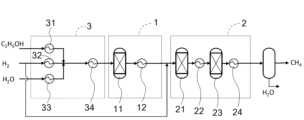
- FIG. 1 is a process flow diagram showing one embodiment of a method for producing a high calorific value fuel gas according to the present invention.
- FIG. 2 is a process flow diagram showing another embodiment of the high heating value fuel gas production method of the present invention.
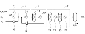
- FIG. 2 is a process flow diagram showing another embodiment of the high heating value fuel gas production method of the present invention.
- FIG. 1 is a block flow diagram showing the method for producing a high calorific value fuel gas according to the present invention.
- the method for producing a high calorific value fuel gas according to this embodiment includes a steam reforming step (steam reforming reaction section 1) in which ethanol is contacted with a catalyst containing ruthenium or nickel under conditions of a catalyst inlet temperature of 200° C. or more and less than 400° C.
- a methanation reaction section 2 in which the gas obtained in the steam reforming step is contacted with a catalyst containing ruthenium or nickel under conditions of a catalyst outlet temperature of 230° C. or more and 330° C. or less.
- the ethanol used in the method for producing high calorific value fuel gas of the present invention does not necessarily have to be produced by fermentation, but from the perspective of producing fuel gas that can be considered carbon neutral, it is preferable that the ethanol be bioethanol produced from raw materials such as sugar cane or corn.
- Ethanol usually contains a small amount of water, and may contain trace amounts of organic acids, aldehydes, thiols, and other sulfur compounds. Of these, water may be present in an amount of about 20% to 50% by mass relative to the ethanol. If the raw ethanol contains water, the amount of water vapor added can be adjusted depending on the amount of water.
- Sulfur compounds such as thiols can cause sulfur poisoning in the downstream steam reforming process and reduce activity, so if a large amount of sulfur compounds are present, it is advisable to carry out desulfurization treatment beforehand.
- the hydrogen used in the high calorific value fuel gas production method of the present invention may be produced by any method, but hydrogen produced using a water electrolysis device such as an alkaline water electrolysis device, a solid polymer water electrolysis device, or a solid oxide water electrolysis device is preferred because it does not usually contain impurities that interfere with the steam reforming process.
- a water electrolysis device such as an alkaline water electrolysis device, a solid polymer water electrolysis device, or a solid oxide water electrolysis device is preferred because it does not usually contain impurities that interfere with the steam reforming process.
- the hydrogen/ethanol molar ratio is 1.0 or more and 10 or less. If the hydrogen/ethanol molar ratio is less than 1.0, it becomes difficult to reduce the carbon dioxide concentration in the fuel gas. If the hydrogen/ethanol molar ratio is greater than 10, it becomes difficult to reduce the hydrogen concentration in the fuel gas.
- the steam/ethanol molar ratio is preferably 1.2 to 5, more preferably 1.5 to 4, and even more preferably 2 to 3.5. If the steam/ethanol molar ratio is less than 1.2, it becomes difficult to suppress carbon deposition on the catalyst. If the steam/ethanol molar ratio is greater than 5, it becomes difficult to reduce the energy required to generate steam, which tends to be economically disadvantageous.
- the method for producing high calorific value fuel gas of the present invention includes a steam reforming step in which a gas containing ethanol, hydrogen, and steam is contacted with a catalyst containing ruthenium or nickel under conditions in which the catalyst inlet temperature is 200°C or higher and lower than 400°C.
- the steam reforming catalyst used in the steam reforming process is a catalyst in which ruthenium or nickel is supported on an inorganic oxide carrier such as alumina.
- a catalyst in which ruthenium is supported on an inorganic oxide carrier such as alumina is particularly preferred because it is less likely to cause carbon deposition.
- the steam reforming process may be carried out in an adiabatic reactor, or may be carried out using a heat exchange reactor to maintain a substantially constant catalyst layer temperature.
- the steam reforming catalyst is filled into the steam reforming reaction section 1 to form a steam reforming catalyst layer.
- the steam reforming process is carried out under conditions where the inlet temperature of the steam reforming catalyst layer is 200°C or higher and lower than 400°C.
- the endothermic steam reforming reaction of ethanol and the exothermic methanation reaction occur simultaneously, resulting in an exothermic reaction overall.
- the inlet temperature of the steam reforming catalyst layer is set to about 300°C and the raw material gas is fed to carry out the reaction under substantially adiabatic conditions, the outlet temperature of the steam reforming catalyst layer is usually about 500°C to 700°C.
- the reaction can be carried out while removing the heat generated by the reaction, so the steam reforming reaction can be carried out while suppressing the rise in catalyst layer temperature, which is advantageous in terms of catalyst durability.
- the reactor is designed and operated appropriately, the heat generated by the reaction can be removed, the inlet temperature of the steam reforming catalyst layer and the outlet temperature of the steam reforming catalyst layer can be made nearly equal, and the reaction can be carried out isothermally.
- the temperature may rise to a temperature close to the outlet temperature of an adiabatic reaction.
- the methanation catalyst used in the methanation step is a catalyst in which ruthenium or nickel is supported on an inorganic oxide carrier such as alumina.
- a catalyst in which ruthenium is supported on an inorganic oxide carrier such as alumina is particularly preferred because it is less likely to cause carbon deposition.
- the methanation step may be carried out in an adiabatic reactor, or may be carried out using a heat exchange reactor to maintain a substantially constant catalyst layer temperature.
- the methanation catalyst is packed into the methanation reaction section 2 to form a methanation catalyst layer.
- the methanation reaction which is an exothermic reaction, proceeds, so if an adiabatic reactor is used for the reaction, the reaction gas will flow out at a temperature higher than the inlet temperature of the methanation catalyst layer. Since the methanation reaction proceeds in equilibrium toward methane production at lower temperatures, it is advantageous to lower the outlet temperature of the methanation catalyst layer from the perspective of obtaining fuel gas with high methane purity, and the process is carried out under conditions where the outlet temperature of the methanation catalyst layer is 330°C or lower. On the other hand, at low temperatures, the activity of the methanation catalyst decreases, and it becomes difficult to allow the reaction to proceed at temperatures below 230°C. Therefore, the outlet temperature of the methanation catalyst layer is set to 230°C or higher and 330°C or lower, and more preferably 230°C or higher and 280°C or lower.
- the methanation reactor is constructed as an adiabatic reactor, multiple reactors are provided and coolers are provided between the reactors so that the inlet temperature of each reaction stage is 230°C or higher and 330°C or lower, more preferably 230°C or higher and 280°C or lower, and the outlet temperature of the catalyst layer in the final stage reactor is 230°C or higher and 330°C or lower.
- the pressure in the steam reforming reaction section 1 in the steam reforming process is preferably 0.3 MPa or more (absolute pressure, the same applies below) because a sufficient reaction rate is easily obtained, and 5 MPa or less is economically advantageous because equipment costs can be suppressed, and is therefore preferably 0.3 MPa or more and 5 MPa or less, and more preferably 0.5 MPa or more and 3 MPa or less.
- the pressure in the methanation reaction section 2 in the methanation process is preferably 0.3 MPa or more and 5 MPa or less, and more preferably 0.5 MPa or more and 3 MPa or less, because a sufficient reaction rate is easily obtained and methanation proceeds in an equilibrium manner when the pressure is 0.3 MPa or more, and a pressure of 5 MPa or less is economically advantageous because equipment costs can be reduced.
- the pressure in the steam reforming reaction section 1 and the pressure in the methanation reaction section 2 should be between 0.3 MPa and 5 MPa, and preferably between 0.5 MPa and 3 MPa. It is not usually necessary to change the pressure between each process, but if necessary, a process of pressurizing or depressurizing the steam reforming reaction section 1 or the methanation reaction section 2 may be added. Normally, the reaction pressure decreases slightly depending on the pressure loss in each process, but this does not pose any particular problems.
- FIG. 2 is a block flow diagram showing another embodiment of the method for producing high calorific value fuel gas of the present invention.
- the raw material gas supplied to the steam reforming process contains at least one of carbon monoxide and carbon dioxide in addition to ethanol, hydrogen, and water vapor.
- the carbon dioxide may be recovered from combustion exhaust gas or exhaust gas from a chemical process using a known carbon dioxide recovery method such as the amine absorption method, or it may be carbon dioxide recovered from the atmosphere. If the carbon dioxide contains sulfur compounds, it may poison and deteriorate the steam reforming catalyst and methanation catalyst, so if necessary, a desulfurization process is performed on the carbon dioxide.
- the carbon monoxide may be synthesized by electrochemically reducing the carbon dioxide described above, or may be reduced by reacting the carbon dioxide with hydrogen (reverse water gas shift reaction).
- Fig. 3 is a block flow diagram showing another embodiment of the method for producing a high calorific value fuel gas of the present invention.
- the method for producing a high calorific value fuel gas according to this embodiment further includes a raw material gas adjustment step in which hydrogen and steam are added to ethanol in the raw material gas adjustment unit 3 to adjust the raw material gas so that the hydrogen/ethanol molar ratio is 1.8 to 2.2 and the steam/ethanol molar ratio is 1.2 to 4, and the adjusted gas after the raw material gas adjustment step is sent to a steam reforming step.
- the hydrogen/ethanol molar ratio fed to the raw gas preparation step is preferably 1.8 or more and 2.2 or less. With this configuration, it is possible to particularly suppress the residual hydrogen and carbon dioxide in the obtained fuel gas to a low level, and a fuel gas with high methane purity and high calorific value that is easy to use as a city gas raw material is obtained. If the hydrogen/ethanol molar ratio is less than 1.8, it may be difficult to reduce the carbon dioxide concentration in the fuel gas. If the hydrogen/ethanol molar ratio is greater than 2.2, it may be difficult to reduce the hydrogen concentration in the fuel gas.
- the steam/ethanol molar ratio fed to the raw material gas preparation step is preferably 1.2 or more and 4 or less.
- the heat generated by the reaction of producing 2 moles of methane and 1 mole of water from 1 mole of ethanol and 2 moles of hydrogen is 156 kJ (25°C), and if all of this is used as the heat of vaporization of water, approximately 3.5 moles of steam can be produced.
- a steam/ethanol molar ratio of 1.5 or more makes it easier to avoid carbon deposition, while a ratio of 3 or less reduces the amount of steam required, which is economically advantageous. Therefore, the steam/ethanol molar ratio is more preferably 1.5 or more and 3 or less.
- methane may be added in an amount that results in a methane/ethanol molar ratio of 0.5 to 1.5.
- Figure 4 is a block flow diagram showing another embodiment of the method for producing high calorific value fuel gas of the present invention.
- the method for producing high calorific value fuel gas according to this embodiment further includes a raw material gas adjustment process in which hydrogen and steam are added to ethanol in the raw material gas adjustment section 3 to adjust the raw material gas so that the hydrogen/ethanol molar ratio is 1.0 or more and less than 1.8, and the steam/ethanol molar ratio is 2 or more and 4 or less, and the adjusted gas after the raw material gas adjustment process is sent to the steam reforming process, and hydrogen is added to the steam reforming reaction section outlet gas obtained in the steam reforming process and sent to the methanation process.
- the hydrogen/ethanol molar ratio fed to the raw gas preparation process is 1.0 or more and less than 1.8.
- the peak temperature of the steam reforming catalyst layer is suppressed when the steam reforming process is performed under adiabatic conditions. If the hydrogen/ethanol molar ratio is 1.5 or less, the suppression effect is greater. If the hydrogen/ethanol molar ratio is less than 1.0, the methanation reaction will proceed more slowly due to a decrease in hydrogen concentration, and the temperature rise due to the progress of the methanation reaction will be small, which may result in the ethanol reforming reaction not proceeding sufficiently. If the hydrogen/ethanol molar ratio is 1.8 or more, the effect of suppressing the peak temperature of the steam reforming catalyst layer will be poor.
- the "peak temperature of the catalyst layer” refers to the maximum temperature of the catalyst layer.
- the steam/ethanol molar ratio is preferably 2 or more and 4 or less, but if the steam/ethanol molar ratio is 2.5 or more, carbon deposition on the catalyst is likely to be suppressed, and if it is 3 or less, the amount of steam required is suppressed, which is likely to be economically advantageous. Therefore, the steam/ethanol molar ratio is preferably 2.5 or more and 3 or less. If the steam/ethanol molar ratio is less than 2.5, the outlet temperature of the steam reforming reaction section will be high and the carbon activity will exceed 1, which may cause deterioration of the steam reforming catalyst due to thermal degradation or carbon deposition. If the steam/ethanol molar ratio is more than 4, a large amount of steam will be required, which may reduce economic efficiency.
- hydrogen is added to the steam reforming reaction section outlet gas obtained in the steam reforming process, and the gas is sent to the methanation process.
- the amount of hydrogen added is the total amount of hydrogen mixed with ethanol in the raw gas adjustment process, and it is preferable to set the molar ratio to ethanol to be 1.8 or more and 2.2 or less, since this makes it easier to obtain a fuel gas with high methane purity and high calorific value, and it is even more preferable for the molar ratio to be 2.0 or more and 2.1 or less.
- FIG. 5 is a block flow diagram showing another embodiment of the method for producing high calorific value fuel gas of the present invention.
- the method for producing high calorific value fuel gas according to this embodiment is configured such that the adjusted gas adjusted in the raw gas adjustment process is mixed with a portion of the steam reforming reaction section outlet gas obtained in the steam reforming process, and then the mixed gas is sent to the steam reforming process.
- the steam reforming process is an exothermic reaction, and the durability of the steam reforming catalyst may become an issue when exposed to high temperatures.
- a portion of the outlet gas from the steam reforming reaction section is mixed with the conditioned gas, diluting the conditioned gas and mitigating the temperature rise in the steam reforming process.
- the raw gas adjustment section 3 may be provided with a recycle compressor 5 for recycling a portion of the outlet gas (steam reforming reaction section outlet gas) of the steam reforming reaction section 1, and a flow rate adjustment means for adjusting the amount of recycling.
- Test Examples 1 to 4 shown below are test examples relating to the steam reforming step of the method for producing a high calorific value fuel gas of the present invention.
- Test Example 1 A sheath tube (outer diameter 6 mm) for temperature measurement was inserted into the center of a stainless steel reaction tube (inner diameter 20 mm), and 12 mL (about 9 g) of a catalyst in which 2 mass% of ruthenium was supported on an activated alumina carrier (2-4 mm spherical) was filled between the reaction tube and the sheath tube to form a catalyst layer. Alumina balls were filled to a height of 30 mm both above and below the catalyst layer.
- This reaction tube was loaded into an electric furnace, and while heating was performed so that the temperature of the center of the alumina ball layer on the catalyst layer reached 250°C, a reducing gas in which 2% hydrogen gas (by volume) was mixed with nitrogen gas was passed through, and reduction treatment was performed for 1 hour.
- the pressure inside the reaction tube was kept at 0.7 MPa (absolute pressure) and the temperature at the center of the alumina ball layer on the catalyst layer, i.e., 15 mm above the top end of the catalyst layer, was heated to 250°C, while a mixture of ethanol at 200 mL/min (volume at standard conditions of 0°C and 1 atm, the same applies below), hydrogen at 400 mL/min, and steam at 400 mL/min was passed from the inlet of the catalyst layer downward through the catalyst layer.
- the condensed components water, ethanol
- the carbon monoxide, carbon dioxide, hydrogen, and nitrogen in the gas were analyzed using a gas chromatograph (Agilent Micro-GC with TCD detector) and the hydrocarbons (methane, ethylene, ethane, propylene, propane, butane) and ethanol were analyzed using a gas chromatograph (Shimadzu GC-2014 with FID detector).
- the ethanol in the condensed water condensed in the ice-cold trap was analyzed using a gas chromatograph (Shimadzu GC-2014, equipped with an FID detector).
- the inlet temperature of the catalyst layer was changed successively to 300°C, 350°C, and 400°C while the test gas was still flowing, and the catalyst layer outlet gas was similarly analyzed by gas chromatography.
- the ethanol conversion rate in the reaction was calculated using the following formula.
- the ethanol contained in the outlet gas from the catalyst layer includes not only the gas that passed through the ice-cold trap, but also ethanol dissolved in the water condensed in the ice-cold trap.
- Ethanol conversion rate [%] 100 ⁇ 1-(amount of ethanol contained in catalyst layer outlet gas per unit time)/(amount of ethanol supplied to catalyst layer per unit time) ⁇
- Table 1 shows the temperatures at the top, middle and bottom of the catalyst layer for each catalyst layer inlet temperature, as well as the analysis results of the gas composition after separation of condensed water, and the ethanol conversion rate.
- the gas produced was mainly methane, containing 88.7% methane, 9.3% hydrogen, and 2.0% carbon dioxide.
- the ethanol conversion rate was 98.0%, with some ethanol remaining in the condensed water.
- the maximum temperature in the catalyst layer was 339°C (top), and 284°C at the outlet of the catalyst layer.
- the gas produced was a gas mainly composed of methane, containing 87.6% methane.
- the ethanol conversion rate was 100%, and no ethanol was detected in the gas or condensed water.
- the maximum temperature in the catalyst layer was 371°C. It is believed that complete conversion of ethanol was achieved because the maximum temperature in the catalyst layer was higher than when the inlet temperature of the catalyst layer was 250°C.
- the outlet temperature of the catalyst layer was increased, and as a result, the methane concentration in the generated gas was slightly lower than when the inlet temperature of the catalyst layer was 300°C.
- Test Example 2 A test was conducted in the same manner as in Test Example 1, except that half of the hydrogen in the raw material gas supplied to the catalyst layer was replaced with nitrogen, so that the flow rates were 200 mL/min of ethanol, 200 mL/min of hydrogen, 200 mL/min of nitrogen, and 400 mL/min of steam. Nitrogen was added so that the total flow rate of the gas supplied to the catalyst per unit time was the same as in Test Example 1.
- Table 2 shows the temperatures at the top, middle and bottom of the catalyst layer for each inlet temperature of the catalyst layer, as well as the analysis results of the gas composition after condensed water separation and the ethanol conversion rate.
- the gas produced was methane-based, with 51.6% methane, 5.9% hydrogen, and 8.7% carbon dioxide, with trace amounts (less than 0.02%) of ethane and propane. Even after removing nitrogen, a large amount of carbon dioxide remained in the produced gas, because stoichiometrically, there was insufficient hydrogen to methanate all the carbon contained in the ethanol. The ethanol conversion was 97.8%, and in addition to the condensed water, some ethanol remained in the gas.
- the maximum temperature in the catalyst bed was 363°C (top and middle), and 336°C at the bottom of the catalyst bed. When the inlet temperature of the catalyst bed was 300°C or higher, the ethanol conversion was 100%, and the only hydrocarbon in the produced gas was methane.
- Test Example 3 The same test as in Test Example 1 was performed except that the total amount of hydrogen in the gas supplied to the catalyst layer was replaced with nitrogen, and the amounts of ethanol, nitrogen, and steam were 200 mL/min, 400 mL/min, and 400 mL/min, respectively.
- Table 3 shows the temperatures at the top, middle and bottom of the catalyst layer for each inlet temperature of the catalyst layer, as well as the analysis results of the gas composition after condensed water separation and the ethanol conversion rate.
- the product gas (after excluding nitrogen) was mainly composed of hydrogen, and contained carbon monoxide, carbon dioxide, methane, and small amounts (0.02% to 4.0%) of C2 to C4 hydrocarbons (ethylene, ethane, propylene, propane, and butane).
- Test Example 4 The test was carried out in the same manner as in Test Example 1, except that the pressure inside the reaction tube was set to 0.1 MPa (absolute pressure).
- Table 4 shows the temperatures at the top, middle and bottom of the catalyst layer for each inlet temperature of the catalyst layer, as well as the analysis results of the gas composition after condensed water separation and the ethanol conversion rate.
- the ethanol conversion rate was only 38.4% when the inlet temperature of the catalyst layer was 250° C., but was 98.0% when the inlet temperature of the catalyst layer was 300° C., and 100% when the inlet temperature of the catalyst layer was 350° C. or higher.
- the methane concentration of the generated gas was lower than that in Test Example 1. This is thought to be because the reaction progresses with an increase in temperature, and the steam reforming reaction of ethanol proceeds quickly when the steam reforming catalyst layer temperature is 400° C. or higher.
- Test Example 1 In Test Example 1, in which hydrogen and steam were added to ethanol so that the hydrogen/ethanol molar ratio and the steam/ethanol molar ratio were 2.0 and the mixture was brought into contact with a catalyst containing ruthenium, the ethanol was almost completely converted to a gas mainly composed of methane if the inlet temperature of the catalyst layer was 250° C. or higher. Furthermore, when the mixture was brought into contact under conditions where the inlet temperature of the catalyst layer was 300° C. or higher and the maximum temperature in the catalyst layer was 370° C. or higher, the ethanol could be completely converted to a gas mainly composed of methane.
- Test Example 3 in which hydrogen was not added, ethanol was not completely converted even when the inlet temperature of the catalyst layer was 400° C. (temperature inside the catalyst layer: 392° C. to 398° C.) As disclosed in Patent Document 3, a temperature of 400° C. or higher is required to obtain a sufficient ethanol conversion rate in a simple steam reforming reaction of ethanol without adding hydrogen.
- Test Example 4 in which the reaction pressure was 0.1 MPa, the ethanol conversion rate was lower in the temperature range of 300°C or lower than in Test Example 1. This suggests that the reaction rate of the steam reforming reaction was reduced.
- the methane concentration in the generated gas was lower than in Test Example 1 is thought to be that the equilibrium conversion rate of the methanation reaction increases as the reaction pressure increases.
- Examples 1 and 2 are examples in which a catalyst is packed in two layers at the inlet and outlet of a long reaction tube, and a raw material gas containing ethanol, hydrogen, and steam is brought into contact with each catalyst layer at different temperatures, with the inlet side performing a steam reforming reaction in the steam reforming reaction section 1 and the outlet side performing a methanation reaction in the methanation reaction section 2, in an attempt to produce a high calorific value fuel gas.
- Example 1 A sheath tube (outer diameter 6 mm) for temperature measurement was inserted through the center of a stainless steel reaction tube (inner diameter 20 mm), and 12 mL (about 9 g) of a catalyst in which 2% by mass of ruthenium was supported on an activated alumina carrier (2-4 mm spherical) was filled between the reaction tube and the sheath tube to form a steam reforming catalyst layer. Alumina balls were filled to a height of 30 mm on the steam reforming catalyst layer.
- Alumina balls were filled to a height of 145 mm below the steam reforming catalyst layer to form a cooling zone for cooling the outlet gas of the steam reforming catalyst layer, and 43 mL (about 33 g) of a catalyst in which 2% by mass of ruthenium was supported on an activated alumina carrier (2-4 mm spherical) was filled below the alumina balls to form a methanation catalyst layer.
- Thermocouples for measuring temperature were installed in the sheath tube at a position corresponding to the center of the alumina ball layer above the steam reforming catalyst layer, at positions corresponding to the upper, middle and lower parts of the steam reforming catalyst layer, and at positions corresponding to the upper, middle and lower parts of the methanation catalyst layer.
- This reaction tube was loaded into an electric furnace.
- the electric furnace consists of three zones, upper, middle, and lower, and the heating output of each can be controlled individually.
- the reaction tube was loaded into the electric furnace so that the bottom end of the steam reforming catalyst layer was positioned at the same height as the bottom end of the upper heater of the electric furnace, and the top and bottom ends of the lower heater were positioned at the same height as the top and bottom ends of the methanation catalyst layer.
- the upper heater was controlled so that the temperature at the center of the alumina ball layer above the steam reforming catalyst layer was approximately 250°C, and the lower heater was controlled so that the temperature at the outlet of the methanation catalyst layer was 250°C.
- a reducing gas consisting of nitrogen gas mixed with 2% hydrogen gas (by volume) was circulated to carry out the reduction process for one hour.
- the pressure inside the reaction tube was kept at 0.7 MPa (absolute pressure), and the upper heater was controlled so that the temperature at the center of the alumina ball layer above the steam reforming catalyst layer (the inlet temperature of the steam reforming catalyst layer) was 300°C, while the lower heater was controlled so that the temperature at the outlet (lower part) of the methanation catalyst layer was 270°C.
- a mixture of ethanol at 200 mL/min, hydrogen at 400 mL/min, and steam at 400 mL/min was circulated from top to bottom through the catalyst layer.
- the catalyst layer outlet gas was analyzed in the same manner as in Test Example 1.
- Table 5 shows the inlet temperature of the steam reforming catalyst layer, the temperatures at the top, middle and bottom of the steam reforming catalyst layer, the temperatures at the top, middle and bottom of the methanation catalyst layer, as well as the analysis results of the gas composition after condensed water separation and the ethanol conversion rate at 1, 2, 3 and 4 hours after the start of the reaction.
- the inlet temperature of the steam reforming catalyst layer was 295°C
- the temperature at the top of the steam reforming catalyst was 392°C
- the outlet temperature (lower part) of the methanation catalyst layer was 269°C.
- the gas was 94.2% methane, 5.3% hydrogen, and 0.5% carbon dioxide, with methane as the main component and small amounts of hydrogen and carbon dioxide.
- the ethanol conversion rate was 100%.
- the inlet temperature of the steam reforming catalyst layer was stably controlled at 299-300°C, the upper temperature of the steam reforming catalyst layer was 397-401°C, and the outlet temperature (lower part) of the methanation catalyst layer was 270-271°C, and the reaction continued stably.
- the gas was stable at 95% methane, 4% hydrogen, and 1% carbon dioxide, and a gas with high methane purity that can be easily used as a city gas feedstock was obtained.
- the ethanol conversion rate remained at 100%.
- Example 2 The test was conducted in the same manner as in Example 1, except that the gas supplied to the steam reforming catalyst layer was a mixture of 200 mL/min of ethanol, 200 mL/min of hydrogen, and 400 mL/min of steam.
- Table 6 shows the inlet temperature of the steam reforming catalyst layer, the temperatures at the top, middle and bottom of the steam reforming catalyst layer, the temperatures at the top, middle and bottom of the methanation catalyst layer, as well as the analysis results of the gas composition after condensed water separation and the ethanol conversion rate at 1, 2, 3 and 4 hours after the start of the reaction.
- the ethanol conversion rate remained stable at 100%.
- the composition of the gas after separation of the condensed water remained stable at 85.5% methane, 1.9% hydrogen, and 12.6% carbon dioxide.
- the obtained gas is mainly composed of methane, but has a slightly high carbon dioxide concentration. In a typical city gas pipeline network, it is difficult to use this gas as a city gas feedstock as it is, but in a city gas pipeline network with a high upper limit on the allowable carbon dioxide concentration, it may be possible to use this gas as a city gas feedstock.
- Example 3 3 this embodiment includes a raw material gas adjustment unit 3 that adjusts the blending of the raw material gas before the raw material gas is supplied to the steam reforming reaction unit 1.
- Ethanol, hydrogen, and water are supplied to the raw material gas adjustment unit 3 in a molar ratio of 1:2:1.2 at a pressure of 0.7 MPa (absolute pressure).
- these are mixed and heated to 300° C. to adjust the raw material gas, and the adjusted gas is sent to the steam reforming reaction unit 1.
- the raw gas comes into contact with the steam reforming catalyst under adiabatic conditions, and the ethanol steam reforming reaction, CO shift reaction, and methanation reaction proceed until a chemical equilibrium state is reached, and the resulting gas is cooled to 250°C and sent to the methanation reaction section 2.
- the CO shift reaction and methanation reaction proceed under isothermal conditions at 250°C, reaching a state of chemical equilibrium, and a fuel gas consisting mainly of methane and water vapor is obtained.
- a fuel gas consisting mainly of methane with small amounts of hydrogen and carbon dioxide is obtained.
- the outlet temperature of the steam reforming reaction section 1 is 619°C.
- the gas composition at the outlet of the steam reforming reaction section 1 is 39.44% methane and 47.48% hydrogen, meaning that the methane concentration is less than 40%, resulting in a gas containing a high concentration of hydrogen.
- the gas composition at the outlet of the methanation reaction section 2 is 96.20% methane, 3.04% hydrogen, and 0.76% carbon dioxide, resulting in fuel gas (high calorific value fuel gas) with a high methane purity sufficient to be used as a city gas feedstock.
- the carbon activity at the outlet of both the steam reforming reaction section 1 and the methanation reaction section 2 is below 1, and carbon deposition is avoided in terms of chemical equilibrium.
- the steam reforming reaction is performed under adiabatic conditions, and the methanation reaction is performed under isothermal conditions, but even in the reaction in an adiabatic reactor, a certain amount of heat is released from the reactor surface, and even in a heat exchange reactor, a local temperature rise may occur.
- the catalyst layer temperature of the methanation catalyst layer is 250°C or higher, and the peak temperature may be about 100°C to 200°C higher than 250°C, depending on the balance between the heat generated by the reaction and the heat removed by heat exchange.
- the outlet temperature of the steam reforming catalyst layer is 619°C if the insulation is perfect, but if the insulation is not perfect, it may be about 100°C to 200°C lower.
- the minimum temperature of the catalyst layer is 250° C. or higher and the maximum temperature is 619° C. or lower. From this perspective, it is desirable that the carbon activity be less than 1 under conditions where the ethanol steam reforming reaction, the CO shift reaction, and the methanation reaction reach equilibrium in the entire temperature range of 250° C. or higher and 619° C. or lower, when the molar ratio of ethanol, hydrogen, and water is 1:2:1.2, and the pressure is 0.7 MPa.
- Figure 6 shows the carbon activity at each temperature when chemical equilibrium is reached. Since the carbon activity is below 1 in the entire temperature range from 250°C to 619°C, carbon deposition is avoided at chemical equilibrium under adiabatic, isothermal, or intermediate conditions.
- Table 8 shows the inlet and outlet temperatures in each reaction section, as well as the composition (volume basis after dehydration) and carbon activity of the outlet gas.
- the outlet temperature of the steam reforming reaction section 1 is 608°C.
- the gas composition at the outlet of the steam reforming reaction section 1 is 39.14% methane and 47.86% hydrogen. Due to the increase in added steam, it becomes more difficult for the methanation reaction, which uses water as a product, to proceed in equilibrium, and the methane concentration is slightly lower than in Example 1.
- the gas composition at the outlet of the methanation reaction section 2 is 95.90% methane, 3.28% hydrogen, and 0.82% carbon dioxide. Although the methane concentration is slightly reduced, the resulting fuel gas (high calorific value fuel gas) has a high methane purity that makes it suitable for use as a city gas feedstock.
- Table 9 shows the inlet and outlet temperatures in each reaction section, as well as the composition (volume basis after dehydration) and carbon activity of the outlet gas.
- the gas composition at the outlet of the methanation reaction section 2 is 95.42% methane, 3.66% hydrogen, and 0.92% carbon dioxide.
- the methane concentration is slightly lower than in Example 4, but the methane is of such high purity that it can be used as a city gas feedstock (high calorific value fuel gas).
- This gas composition is found to be almost identical to the gas composition obtained in Example 1 (94.9% methane, 4.2% hydrogen, 0.9% carbon dioxide), which had the same molar ratio of ethanol, hydrogen, and water, and had almost the same outlet temperature and reaction pressure as the methanation catalyst layer.
- Table 10 shows the inlet and outlet temperatures in each reaction section, as well as the composition (volume basis after dehydration) and carbon activity of the outlet gas.
- the outlet temperature of the steam reforming reaction section 1 is 562°C. This is more than 50°C lower than in Example 3, but this is because the temperature rise is mitigated by the increased amount of steam added, which is advantageous in terms of the durability of the steam reforming catalyst.
- the gas composition at the outlet of the methanation reaction section 2 is 94.51% methane, 4.39% hydrogen, and 1.10% carbon dioxide.
- the methane concentration is slightly lower than in Example 5, but the fuel gas (high calorific value fuel gas) has a high methane purity that makes it suitable for use as a city gas feedstock.
- Table 11 shows the inlet and outlet temperatures in each reaction section, as well as the composition (volume basis after dehydration) and carbon activity of the outlet gas.
- the outlet temperature of the steam reforming reaction section 1 was 628°C.
- the carbon activity at the outlet of the steam reforming reaction section 1 exceeded 1.
- the amount of steam added was small, which resulted in a higher outlet temperature of the steam reforming reaction section 1 and a carbon activity exceeding 1, raising concerns about deterioration of the steam reforming catalyst due to thermal degradation and carbon precipitation.
- the outlet temperature of the steam reforming reaction section 1 is 518°C.
- the gas composition at the outlet of the steam reforming reaction section 1 is 49.36% methane and 25.09% hydrogen.
- the methane concentration is higher compared to Example 1. This is thought to be because the outlet temperature is lower compared to Example 1, making it easier for the methanation reaction to proceed in equilibrium.
- the gas composition at the outlet of the methanation reaction section 2 is 73.87% methane, 1.13% hydrogen, and 25.00% carbon dioxide, making it difficult to use as a city gas feedstock unless the carbon dioxide is removed.
- a further problem is that the carbon activity exceeds 1 at both the outlet of the steam reforming reaction section 1 and the outlet of the methanation reaction section 2, raising concerns about deterioration of the steam reforming catalyst and methanation catalyst due to carbon deposition.
- Table 13 shows the inlet and outlet temperatures in each reaction section, as well as the composition (volume basis after dehydration) and carbon activity of the outlet gas.
- the outlet temperature of the steam reforming reaction section 1 was 502°C, and the carbon activity was below 1.
- the gas composition at the outlet of methanation reaction section 2 is 73.66% methane, 1.33% hydrogen, and 25.00% carbon dioxide, and cannot be used as a raw material for city gas unless the carbon dioxide is removed.
- the carbon activity at the outlet of methanation reaction section 2 exceeds 1, raising concerns about deterioration of the methanation catalyst due to carbon deposition.
- the temperature at the outlet of the steam reforming reaction section 1 was 488°C.
- the gas composition at the outlet of the methanation reaction section 2 is 73.46% methane, 1.54% hydrogen, and 25.00% carbon dioxide, and it is difficult to use it as a city gas raw material unless the carbon dioxide is removed.
- the carbon activity at both the outlet of the steam reforming reaction section 1 and the outlet of the methanation reaction section 2 is below 1, and carbon deposition is avoided at chemical equilibrium.
- the results of Comparative Examples 2 to 4 show that in simple steam reforming of ethanol without coexistence of hydrogen, in order to avoid carbon deposition at equilibrium, it is necessary to add steam so that the molar ratio of steam to ethanol is 3 or more (the molar ratio to the methane produced is 2 or more).
- Table 15 shows the inlet and outlet temperatures in each reaction section, as well as the composition (volume basis after dehydration) and carbon activity of the outlet gas.
- the gas composition at the outlet of the methanation reaction section 2 was 80.00% methane and 20.00% hydrogen, which means it contained a relatively high concentration of hydrogen, but the concentrations of carbon monoxide and carbon dioxide were both less than 0.01%.
- the gas composition at the outlet of methanation reaction section 2 was 91.28% methane, 2.08% hydrogen, and 6.64% carbon dioxide.
- the gas composition at the outlet of methanation reaction section 2 was 85.67% methane, 1.63% hydrogen, and 12.70% carbon dioxide.
- This gas composition is found to be almost identical to the gas composition (85.5% methane, 1.9% hydrogen, 12.6% carbon dioxide) obtained in Example 2, which had the same molar ratio of ethanol, hydrogen, and water, and had almost the same methanation catalyst layer outlet temperature and reaction pressure.
- Example 2 The carbon activity at both the outlet of the steam reforming reaction section 1 and the outlet of the methanation reaction section 2 was below 1.
- the gas composition did not change over a period of four hours, and a stable methane-based gas was obtained. It is presumed that the carbon activity being well below 1 under these reaction conditions enabled a stable reaction.
- Example 10 In this embodiment, a trial calculation example of a fuel gas production process is shown. The process flow is shown in FIG.
- the raw gas adjustment section 3 where the raw gas adjustment process is carried out, is supplied with ethanol, hydrogen, and water at flow rates of 1 mol/s, 2.0 mol/s, and 2.0 mol/s, respectively, at a temperature of 25°C and a pressure of 0.8 MPa.
- the raw gas adjustment section 3 is equipped with heat exchangers 31 to 34.
- Ethanol, hydrogen and water are heated and mixed to become a raw material gas, which is then heated further to 300°C and sent to the steam reforming reaction section 1.
- the steam reforming reaction section 1, where the steam reforming process takes place, is equipped with a steam reforming reactor 11 and a heat exchanger 12.
- the raw material gas is fed into the steam reforming reactor 11, where the ethanol steam reforming reaction, the CO shift reaction, and the methanation reaction proceed adiabatically.
- the outlet gas of the steam reforming reactor 11 is cooled to 250°C in the heat exchanger 12, and then fed into the methanation reaction section 2.
- the methanation reaction section 2 where the methanation process takes place, is equipped with a first methanation reactor 21, a heat exchanger 22, a second methanation reactor 23, and a heat exchanger 24.
- the first methanation reactor 21 is an adiabatic reactor, and its outlet gas is cooled to 250°C in a heat exchanger 22 before being sent to the second methanation reactor 23.
- the second methanation reactor 23 is a heat exchange type reactor, and the methanation reaction proceeds while maintaining the temperature at approximately 250°C, until the methanation reaction reaches the equilibrium composition at 250°C.
- the outlet gas of the second methanation reactor 23 is cooled in a heat exchanger 24, and when the water is separated and dehydrated, it becomes a fuel gas whose main component is methane.
- the composition of the resulting fuel gas (by volume after dehydration) is 95.65% methane, 3.48% hydrogen, 0.87% carbon dioxide, and 2 ppm carbon monoxide. It can be seen that the method of the present invention can produce a fuel gas with high methane purity (high calorific value fuel gas) that can be used as city gas.
- the raw material gas is heated to 300°C and fed to the steam reforming reaction section 1, and the methanation reaction proceeds in the second methanation reactor 23 while maintaining the temperature at approximately 250°C. Therefore, at the outlet of each reactor, the carbon activity is below 1, and it is expected that carbon deposition will be avoided in terms of chemical equilibrium.
- Example 11 The calculation was performed in the same manner as in Example 10, except that the flow rate of hydrogen was changed from 2.0 mol/s to 1.0 mol/s.
- the temperatures and flow rates at key points in the process are shown in Table 19.
- composition of the resulting fuel gas (by volume after dehydration) is 85.78% methane, 1.53% hydrogen, 12.69% carbon dioxide, and 18 ppm carbon monoxide.
- the raw material gas is heated to 300°C and fed to the steam reforming reaction section 1, and the methanation reaction proceeds in the second methanation reactor 23 while maintaining the temperature at approximately 250°C. Therefore, at the outlet of each reactor, the carbon activity is below 1, and it is expected that carbon deposition will be avoided in terms of chemical equilibrium.
- Example 12 In this example, a trial calculation example of a fuel gas production process in the form shown in the block flow diagram of Fig. 4 is shown. The process flow is shown in Fig. 9.
- Ethanol, hydrogen and water are heated and mixed to become a raw material gas, which is then heated further to 300°C and sent to the steam reforming reaction section 1.
- the steam reforming reaction section 1, where the steam reforming process takes place, is equipped with a steam reforming reactor 11 and a heat exchanger 12.
- the raw material gas is fed into the steam reforming reactor 11, where the ethanol steam reforming reaction, the CO shift reaction, and the methanation reaction proceed adiabatically.
- the outlet gas of the steam reforming reactor 11 is cooled to a predetermined temperature in the heat exchanger 12, and then 1.0 mol/s of hydrogen is added from the hydrogen supply line entering the raw material gas adjustment section 3, and the gas is fed into the methanation reaction section 2 at 250°C.
- the methanation reaction section 2 where the methanation process takes place, is equipped with a first methanation reactor 21, a heat exchanger 22, a second methanation reactor 23, and a heat exchanger 24.
- the first methanation reactor 21 is an adiabatic reactor, and its outlet gas is cooled to 250°C in a heat exchanger 22 before being sent to the second methanation reactor 23.
- the second methanation reactor 23 is a heat exchange type reactor, and the methanation reaction proceeds while maintaining the temperature at approximately 250°C, until the methanation reaction reaches the equilibrium composition at 250°C.
- the outlet gas of the second methanation reactor 23 is cooled in a heat exchanger 24, and when the water is separated and dehydrated, it becomes a fuel gas whose main component is methane.
- the composition of the resulting fuel gas (volume basis after dehydration) is 95.65% methane, 3.48% hydrogen, 0.87% carbon dioxide, and 2 ppm carbon monoxide. It can be seen that the method of the present invention can produce a fuel gas with high methane purity (high calorific value fuel gas) that can be used as city gas. In addition, the carbon activity at the outlet of each reactor is below 1, and carbon deposition is avoided in terms of chemical equilibrium.
- Example 10 Comparing Example 10 and Example 12, the composition of the resulting fuel gas is the same.
- the temperature at the outlet of the steam reforming reactor is 596°C in Example 10, whereas it is 568°C in Example 12, which is about 30°C lower.
- Example 12 This is because, under the conditions of Example 12, there is a stoichiometric shortage of hydrogen to methanate all the carbon in ethanol, and the progress of the methanation reaction, which is an exothermic reaction, is low. Therefore, introducing a portion of the hydrogen into the methanation reaction inlet, bypassing the steam reforming reactor, has the effect of suppressing thermal degradation of the catalyst used in the steam reforming reaction.
- Example 13 In this example, a trial calculation example of a fuel gas production process in the form shown in the block flow diagram of Fig. 5 is shown. The process flow is shown in Fig. 10.
- ethanol, hydrogen, and water are supplied at flow rates of 1 mol/s, 2.0 mol/s, and 2.0 mol/s, respectively, at a temperature of 25°C and a pressure of 0.8 MPa.
- these are heated and mixed, and are mixed with the recycled gas from the outlet of the steam reforming reactor 11, heated to 300°C, and turned into raw gas, which is sent to the steam reforming process.
- the raw gas is fed into the steam reforming reactor 11, where the reaction proceeds adiabatically.
- the outlet gas of the steam reforming reactor 11 is cooled to 250°C, and one-third of it is returned to the raw gas preparation process through the recycle compressor 5, and the remainder is fed into the first methanation reactor 21.
- the first methanation reactor 21 is an adiabatic reactor, and its outlet gas is cooled to 250°C in the heat exchanger 22, and then fed into the second methanation reactor 23.
- the second methanation reactor 23 is a heat exchange type reactor, and the methanation reaction proceeds while maintaining the temperature at approximately 250°C, and the methanation reaction proceeds until the equilibrium composition at 250°C is reached.
- the outlet gas of the second methanation reactor 23 is cooled in the heat exchanger 24, and when the water is separated and dehydrated, it becomes a fuel gas mainly composed of methane.
- the composition of the resulting fuel gas (volume basis after dehydration) is 95.65% methane, 3.48% hydrogen, 0.87% carbon dioxide, and 2 ppm carbon monoxide. It can be seen that the method of the present invention can produce a fuel gas with high methane purity (high calorific value fuel gas) that can be used as city gas. In addition, the carbon activity at the outlet of each reactor is below 1, and carbon deposition is avoided in terms of chemical equilibrium.
- Example 10 Comparing Example 10 and Example 13, the composition of the resulting fuel gas is the same.
- the temperature at the outlet of the steam reforming reactor is 596°C in Example 10, while it is 559°C in Example 12, which is about 40°C lower. This is because part of the outlet gas of the steam reforming reaction section is returned to the inlet of the steam reforming reactor for recycling, thereby diluting the reaction gas and suppressing the temperature rise. By returning part of the outlet gas of the steam reforming reaction section to the inlet of the steam reforming reactor, thermal deterioration of the catalyst used in the steam reforming reaction is suppressed.
- Example 13 the hydrogen/ethanol molar ratio and steam/ethanol molar ratio at the stage of preparation by mixing ethanol with hydrogen and steam are 2.0 and 2.0, respectively, but since the gas is mixed with the gas returned from the outlet gas of the steam reforming process and then fed to the steam reforming process, the hydrogen/ethanol molar ratio at the inlet of the steam reforming process is 2.736 and the steam/ethanol molar ratio is 3.148, which are slightly different.
- Example 14 This example shows a trial calculation example of a fuel gas production process in which the raw material supplied to the steam reforming step further contains carbon dioxide, as shown in the block flow diagram of Figure 2. As in Example 13, a configuration was adopted in which a portion of the gas at the outlet of the steam reforming reaction section was returned to the inlet of the steam reforming reactor.
- ethanol, hydrogen, water and carbon dioxide are supplied at flow rates of 1 mol/s, 6.0 mol/s, 2.0 mol/s and 1.0 mol/s, respectively, at a temperature of 25°C and a pressure of 0.8 MPa.
- these are heated and mixed, and are mixed with the recycled gas from the outlet of the steam reforming reactor 11, heated to 300°C, and turned into raw gas, which is sent to the steam reforming process.
- the raw gas is fed into the steam reforming reactor 11, where the reaction proceeds adiabatically.
- the outlet gas of the steam reforming reactor 11 is cooled to 250°C, and one-third of it is returned to the raw gas preparation process through the recycle compressor 5, and the remainder is fed into the first methanation reactor 21.
- the first methanation reactor 21 is an adiabatic reactor, and its outlet gas is cooled to 250°C in the heat exchanger 22, and then fed into the second methanation reactor 23.
- the second methanation reactor 23 is a heat exchange type reactor, and the methanation reaction proceeds while maintaining the temperature at approximately 250°C, and the methanation reaction proceeds until the equilibrium composition at 250°C is reached.
- the outlet gas of the second methanation reactor 23 is cooled in the heat exchanger 24, and when the water is separated and dehydrated, it becomes a fuel gas mainly composed of methane.
- the composition of the resulting fuel gas (volume basis after dehydration) is 95.35% methane, 3.72% hydrogen, 0.93% carbon dioxide, and 2 ppm carbon monoxide. It can be seen that the method of the present invention can produce a fuel gas with high methane purity (high calorific value fuel gas) that can be used as city gas. In addition, the carbon activity at the outlet of each reactor is below 1, and carbon deposition is avoided in terms of chemical equilibrium.
- the raw material gas is prepared by mixing ethanol with hydrogen, steam, and carbon dioxide, so the hydrogen/ethanol molar ratio at the raw material gas preparation stage is 6.0, and this is further mixed with the gas returned from the steam reforming process outlet gas before being sent to the steam reforming process, so the hydrogen/ethanol molar ratio at the steam reforming process inlet is 7.581, and the steam/ethanol molar ratio is 3.768, which are somewhat large.
- Examples 3 to 14 examples were particularly described in which the steam reforming reactor used in the steam reforming process was configured as an adiabatic reactor.
- the reactor used in the steam reforming process according to the present invention is not particularly limited, and may be configured as a heat exchange reactor.
- the methanation reactor used in the methanation step was particularly described as being configured with an adiabatic first methanation reactor 21 and a heat exchanger second methanation reactor 23.
- the reactor used in the methanation step according to the present invention is not particularly limited as long as the outlet temperature of the catalyst layer in the final stage of the methanation reactor is 230°C or higher and 330°C or lower, and may be configured with two or more stages of adiabatic reactors connected together, or may be configured with two or more stages of heat exchanger reactors connected together.
- a steam reforming reactor and a methanation reactor used in the methanation step are housed in separate reactors, and a heat exchanger is further provided so that the gas leaving the steam reforming reactor is cooled by passing through the heat exchanger before being inserted into the methanation reactor.
- the steam reforming reactor and methanation reactor of the present invention may be integrally configured, and for example, a single reactor may be filled with the same or different catalysts, and a heat exchanger may not be provided near the inlet, or the heat exchange function near the inlet may be designed to be smaller than that near the outlet, allowing the reaction to proceed under adiabatic or similar conditions in the first half of the reactor and isothermal or similar conditions in the second half.
- the raw material gas is introduced into the steam reforming reactor at 300°C, and the reaction proceeds adiabatically in the first half, with the catalyst layer temperature peaking at, for example, about 400°C, while in the second half, the gas generated by the steam reforming reaction is gradually cooled, the methanation reaction proceeds, and the gas leaves the reactor at a temperature between 230°C and 330°C.
- the steam reforming process is carried out in the first half of the reactor, and the methanation process is carried out in the second half of the reactor.
- the present invention does not exclude the use of conventionally known means for improving methane conversion.
- the reaction gas may be cooled in the middle of a multi-stage reaction to condense and separate a portion of the water vapor.
- the method of the present invention can be used to reduce the hydrogen and carbon dioxide concentrations in the fuel gas without excessively removing water vapor.
- the present invention does not exclude the use of conventionally known means for improving methane purity. For example, by adding a small amount of oxygen to the fuel gas after the methanation reaction and performing a selective oxidation reaction that selectively oxidizes only hydrogen, it is possible to reduce hydrogen in the fuel gas after the methanation reaction and obtain fuel gas with a higher methane purity.
- the raw material gas contains carbon dioxide, but this is not limited to this example, and the raw material gas may contain carbon monoxide, or may contain carbon monoxide and carbon dioxide.
- the present invention can be used, for example, as a method for producing fuel gas to be supplied as city gas.
Landscapes
- Chemical & Material Sciences (AREA)
- Organic Chemistry (AREA)
- Oil, Petroleum & Natural Gas (AREA)
- Engineering & Computer Science (AREA)
- Chemical Kinetics & Catalysis (AREA)
- General Chemical & Material Sciences (AREA)
- Hydrogen, Water And Hydrids (AREA)
Priority Applications (2)
| Application Number | Priority Date | Filing Date | Title |
|---|---|---|---|
| PCT/JP2022/042576 WO2024105814A1 (ja) | 2022-11-16 | 2022-11-16 | 高発熱量燃料ガスの製造方法 |
| JP2024558568A JPWO2024105814A1 (https=) | 2022-11-16 | 2022-11-16 |
Applications Claiming Priority (1)
| Application Number | Priority Date | Filing Date | Title |
|---|---|---|---|
| PCT/JP2022/042576 WO2024105814A1 (ja) | 2022-11-16 | 2022-11-16 | 高発熱量燃料ガスの製造方法 |
Publications (1)
| Publication Number | Publication Date |
|---|---|
| WO2024105814A1 true WO2024105814A1 (ja) | 2024-05-23 |
Family
ID=91084038
Family Applications (1)
| Application Number | Title | Priority Date | Filing Date |
|---|---|---|---|
| PCT/JP2022/042576 Ceased WO2024105814A1 (ja) | 2022-11-16 | 2022-11-16 | 高発熱量燃料ガスの製造方法 |
Country Status (2)
| Country | Link |
|---|---|
| JP (1) | JPWO2024105814A1 (https=) |
| WO (1) | WO2024105814A1 (https=) |
Citations (4)
| Publication number | Priority date | Publication date | Assignee | Title |
|---|---|---|---|---|
| JPS56120796A (en) * | 1980-01-31 | 1981-09-22 | British Gas Corp | Gas manufacture |
| JP2009227588A (ja) * | 2008-03-19 | 2009-10-08 | Osaka Gas Co Ltd | メタン含有ガス製造方法、及びメタン含有ガス製造用触媒 |
| JP2013540674A (ja) * | 2010-08-18 | 2013-11-07 | ペトロレオ ブラジレイロ ソシエダ アノニマ − ペトロブラス | エタノールからの水素の製造方法 |
| JP2022176895A (ja) * | 2021-05-17 | 2022-11-30 | 大阪瓦斯株式会社 | 高発熱量燃料ガスの製造方法 |
-
2022
- 2022-11-16 JP JP2024558568A patent/JPWO2024105814A1/ja active Pending
- 2022-11-16 WO PCT/JP2022/042576 patent/WO2024105814A1/ja not_active Ceased
Patent Citations (4)
| Publication number | Priority date | Publication date | Assignee | Title |
|---|---|---|---|---|
| JPS56120796A (en) * | 1980-01-31 | 1981-09-22 | British Gas Corp | Gas manufacture |
| JP2009227588A (ja) * | 2008-03-19 | 2009-10-08 | Osaka Gas Co Ltd | メタン含有ガス製造方法、及びメタン含有ガス製造用触媒 |
| JP2013540674A (ja) * | 2010-08-18 | 2013-11-07 | ペトロレオ ブラジレイロ ソシエダ アノニマ − ペトロブラス | エタノールからの水素の製造方法 |
| JP2022176895A (ja) * | 2021-05-17 | 2022-11-30 | 大阪瓦斯株式会社 | 高発熱量燃料ガスの製造方法 |
Also Published As
| Publication number | Publication date |
|---|---|
| JPWO2024105814A1 (https=) | 2024-05-23 |
Similar Documents
| Publication | Publication Date | Title |
|---|---|---|
| US12180072B2 (en) | Chemical synthesis plant | |
| Byrd et al. | Hydrogen production from glycerol by reforming in supercritical water over Ru/Al2O3 catalyst | |
| CA2902113C (en) | Process for producing hydrocarbons from a naphtha free hydrocarbon feedstock | |
| US7795317B2 (en) | Process to prepare a Fischer-Tropsch synthesis product | |
| US20100216633A1 (en) | Oil- based thermo-neutral reforming with a multi-component catalyst | |
| RS20060418A (sr) | Integrisani postupak za sintezu sirćetne kiseline i metanola | |
| CN104703913A (zh) | 生产合成气的方法 | |
| RU2510883C2 (ru) | Способ получения синтез-газа для производства аммиака | |
| MX2012013556A (es) | Proceso para la preparacion de gas de sintesis. | |
| CA3126620A1 (en) | Chemical synthesis plant and method for utilization of carbon dioxide | |
| CA3195610A1 (en) | Syngas stage for chemical synthesis plant | |
| US7001574B2 (en) | Apparatus for producing high molecular weight liquid hydrocarbons from methane and/or natural gas | |
| EP1858802B1 (en) | Process to prepare a mixture of carbon monoxide and hydrogen | |
| JP7829396B2 (ja) | 高発熱量燃料ガスの製造方法 | |
| JP4781652B2 (ja) | 合成ガスの製法および製造装置 | |
| NO169647B (no) | Fremgangsmaate for fremstilling av vaeskeformige hydrocarboner ut fra et gassformig hydrocarbonholdig tilfoerselsmateriale | |
| WO2024105814A1 (ja) | 高発熱量燃料ガスの製造方法 | |
| CA2852267A1 (en) | Systems and methods for the use of fischer-tropsch tail gas in a gas to liquid process | |
| JP7617755B2 (ja) | 燃料ガスの製造方法 | |
| US3975169A (en) | Process for producing a natural gas substitute | |
| US12492154B2 (en) | Method for producing fuel gas | |
| JP2025536722A (ja) | H2およびco2含有オフガスの合成燃料への変換 | |
| JP7692305B2 (ja) | 高発熱量燃料ガスの製造方法及び高発熱量燃料ガスの製造設備 | |
| WO2025059409A1 (en) | Method and system for converting non-methane hydrocarbons to recover hydrogen gas and/or methane gas therefrom | |
| JP2025540309A (ja) | 炭素酸化物から持続可能な航空燃料(saf)への転化方法 |
Legal Events
| Date | Code | Title | Description |
|---|---|---|---|
| 121 | Ep: the epo has been informed by wipo that ep was designated in this application |
Ref document number: 22965790 Country of ref document: EP Kind code of ref document: A1 |
|
| WWE | Wipo information: entry into national phase |
Ref document number: 2024558568 Country of ref document: JP |
|
| REG | Reference to national code |
Ref country code: BR Ref legal event code: B01A Ref document number: 112025007429 Country of ref document: BR |
|
| WWE | Wipo information: entry into national phase |
Ref document number: 2501003020 Country of ref document: TH |
|
| NENP | Non-entry into the national phase |
Ref country code: DE |
|
| ENP | Entry into the national phase |
Ref document number: 112025007429 Country of ref document: BR Kind code of ref document: A2 Effective date: 20250415 |
|
| 122 | Ep: pct application non-entry in european phase |
Ref document number: 22965790 Country of ref document: EP Kind code of ref document: A1 |