WO2024101334A1 - 太陽光発電システムおよび制御方法 - Google Patents
太陽光発電システムおよび制御方法 Download PDFInfo
- Publication number
- WO2024101334A1 WO2024101334A1 PCT/JP2023/039976 JP2023039976W WO2024101334A1 WO 2024101334 A1 WO2024101334 A1 WO 2024101334A1 JP 2023039976 W JP2023039976 W JP 2023039976W WO 2024101334 A1 WO2024101334 A1 WO 2024101334A1
- Authority
- WO
- WIPO (PCT)
- Prior art keywords
- power
- power supply
- storage device
- string
- power generation
- Prior art date
- Legal status (The legal status is an assumption and is not a legal conclusion. Google has not performed a legal analysis and makes no representation as to the accuracy of the status listed.)
- Ceased
Links
Images








Classifications
-
- H—ELECTRICITY
- H02—GENERATION; CONVERSION OR DISTRIBUTION OF ELECTRIC POWER
- H02J—ELECTRIC POWER NETWORKS; CIRCUIT ARRANGEMENTS OR SYSTEMS FOR SUPPLYING OR DISTRIBUTING ELECTRIC POWER; SYSTEMS FOR STORING ELECTRIC ENERGY
- H02J7/00—Circuit arrangements for charging or discharging batteries or for supplying loads from batteries
- H02J7/34—Parallel operation in networks using both storage and other DC sources, e.g. providing buffering
- H02J7/35—Parallel operation in networks using both storage and other DC sources, e.g. providing buffering with light sensitive cells
-
- H—ELECTRICITY
- H02—GENERATION; CONVERSION OR DISTRIBUTION OF ELECTRIC POWER
- H02S—GENERATION OF ELECTRIC POWER BY CONVERSION OF INFRARED RADIATION, VISIBLE LIGHT OR ULTRAVIOLET LIGHT, e.g. USING PHOTOVOLTAIC [PV] MODULES
- H02S10/00—PV power plants; Combinations of PV energy systems with other systems for the generation of electric power
- H02S10/20—Systems characterised by their energy storage means
Definitions
- the present invention relates to a solar power generation system, etc.
- Such power storage devices are generally stationary, installed in a fixed location, and are usually configured and installed as an integrated system that is premised on being connected to a commercial power grid (see, for example, Patent Document 1).
- the storage device to be installed can be determined in advance and the entire system can be planned, a power generation system with higher efficiency in all respects, including power generation and storage, can be realized. For this reason, traditionally, the specifications of the storage device were determined at the time of system design and the device was made a fixed type that was installed in a fixed location. However, if the storage device could be made an optional replaceable storage device rather than a fixed type that is installed in a fixed location, it would be possible to store electricity in the storage device over and over again, and there is a possibility that the electricity generated by solar power generation could be used effectively. However, there are various specifications for storage devices, such as capacity and voltage (rated voltage and voltage range), and accordingly, there are various appropriate charging methods, such as control of charging voltage and charging current.
- the problem that this invention aims to solve is to realize a solar power generation system that can properly charge a replaceable power storage device.
- the first invention is A solar power generation system in which a power storage device that is charged with power generated by solar power generation is configured to be replaceable, N strings (N ⁇ 2); M (M ⁇ 2) power supply units electrically connectable to the power storage device; M DC/DC converters provided for each of the power supply units for supplying charging power to a power storage device connected to the power supply unit; a switching unit capable of switching a connection relationship between each of the strings and each of the DC/DC converters; A controller for controlling the switching unit; Equipped with The switching unit is a power supply destination switching unit that switches a DC/DC converter to which power is supplied among the M DC/DC converters; a string connection switching unit that switches a string connection, which is a connection relationship of the strings that are connected to the power supply destination; having The controller controls the power supply destination switching unit and the string connection switching unit based on a power supply unit to which the power storage device is connected among the M power supply units. It is a solar power generation system.
- a method for controlling a solar power generation system in which a power storage device that is charged with power generated by solar power generation is configured to be replaceable comprising the steps of:
- the solar power generation system includes: N strings (N ⁇ 2); M (M ⁇ 2) power supply units electrically connectable to the power storage device; M DC/DC converters provided for each of the power supply units for supplying charging power to a power storage device connected to the power supply unit; a switching unit capable of switching a connection relationship between each of the strings and each of the DC/DC converters; Equipped with The switching unit is a power supply destination switching unit that switches a DC/DC converter to which power is supplied among the M DC/DC converters; a string connection switching unit that switches a string connection, which is a connection relationship of the strings that are connected to the power supply destination; It has controlling the power supply destination switching unit and the string connection switching unit based on a power supply unit to which the power storage device is connected among the M power supply units;
- a control method may be configured.
- the string connection which is the connection relationship of the strings connected to the power supply units to which power is supplied, can be switched by controlling the switching unit by the controller.
- This makes it possible to switch to an appropriate string connection according to the connected storage device. Therefore, it becomes possible to appropriately charge a plurality of replaceable storage devices. For example, by configuring the string connection so that the voltage output matches the specifications of the connected storage device, it becomes possible to suppress the conversion loss in the DC/DC converter as much as possible, and more efficient charging can be realized. If there are a plurality of storage devices connected, it is also possible to configure the string connection so that they are charged in parallel, or to configure the string connection so that charging power is preferentially allocated to the storage device that needs to be charged early.
- the second invention is the above-mentioned invention, the string connection switching unit switches between an individual connection in which the strings are individually connected to the power supply destination, a parallel connection in which the strings are connected in parallel, and a series connection in which the strings are connected in series. It is a solar power generation system.
- various voltages and currents of power can be supplied as charging power depending on the combination and number of strings to be connected, and the difference in string connection such as individual connection, parallel connection, or series connection.
- This enables appropriate charging control according to the specifications of the storage device, such as the capacity and voltage (rated voltage and voltage range).
- the storage device such as the capacity and voltage (rated voltage and voltage range).
- it is possible to configure string connections so that they are charged in parallel, or to configure string connections so that charging power is preferentially allocated to storage devices that need to be charged quickly.
- the third invention is the above-mentioned invention,
- the power storage device having a different voltage specification can be connected to the power supply unit, a voltage specification data acquisition unit that acquires voltage specification data of the power storage device connected to the power supply unit; Further comprising:
- the controller controls the string connection switching unit based on voltage specification data of the power storage device connected to the power supply unit. It is a solar power generation system.
- the switching unit by controlling the switching unit to establish a string connection that supplies power of a voltage corresponding to the voltage specification of the storage device to the power supply unit based on the voltage specification data of the storage device connected to the power supply unit, appropriate charging control for storage devices with various voltage specifications becomes possible.
- a fourth aspect of the present invention is the above-mentioned invention
- the N strings include strings with different power generation specifications related to a power generation voltage and a power generation current
- the controller controls the string connection switching unit based on voltage specification data of the power storage device connected to the power supply unit and power generation specifications of the string. It is a solar power generation system.
- the N strings include strings with different power generation specifications, so it is possible to vary the voltage and current of the power supplied to the power supply unit depending on the combination of strings connected to the power supply unit and their connection relationships.
- a fifth aspect of the present invention is the above-mentioned invention,
- the string is configured by connecting photovoltaic power generation modules in series, and connecting a bypass diode to each of the modules or each of the clusters constituting the modules, a bypass diode operation state acquisition unit that acquires an operation state of the bypass diode; Further comprising: The controller dynamically controls the string connection switching unit based on voltage specification data of the power storage device connected to the power supply unit, power generation specifications of the string, and the operation state acquired by the bypass diode operation state acquisition unit. It is a solar power generation system.
- the fifth invention by dynamically controlling the string connection switching unit based on the operating state of the bypass diode, it becomes possible to dynamically switch the string connection connected to the power supply unit to which the power is supplied.
- This enables more appropriate charging control of the power storage device.
- the power generation status related to the generated voltage and generated current of the string may change due to changes in solar radiation due to shading, adhesion of dust, etc., or failure of the solar cell.
- a sixth aspect of the present invention is the above-mentioned invention, a power generation status acquisition unit that acquires a power generation status related to a generated voltage and a generated current of each of the N strings; Further comprising: The controller dynamically controls the string connection switching unit based on voltage specification data of the power storage device connected to the power supply unit and the power generation status of each string acquired by the power generation status acquisition unit. It is a solar power generation system.
- the sixth invention by dynamically controlling the string connection switching unit based on the power generation status of each string, it becomes possible to dynamically switch the string connection connected to the power supply unit to which the power is supplied.
- the power generation status related to the generated voltage and generated current of the string may change due to changes in solar radiation due to shading, adhesion of dirt, etc., or failure of the solar cell.
- the power generation status of each string can be obtained, it becomes possible to dynamically control the string connection switching unit to switch to a string connection that can supply power optimal for the voltage specifications of the power storage device connected to the power supply unit according to changes in the current power generation status of the string. This enables more appropriate charging control according to the power generation status of the string.
- a seventh aspect of the present invention is the above-mentioned invention, a charging status acquisition unit that acquires a charging status of the power storage device connected to the power supply unit; Further comprising: The controller dynamically controls the power supply destination switching unit and the string connection switching unit based on the charging status. It is a solar power generation system.
- the seventh invention it is possible to dynamically control the power supply destination switching unit to switch the power supply unit to which power is supplied based on the charging status of the power storage device, and dynamically control the string connection switching unit to switch the string connection to be connected to the power supply unit to which power is supplied.
- This enables more appropriate charging control of the power storage devices. For example, when simultaneously charging multiple power storage devices, it is possible to control the switching unit to disconnect the power supply unit to which a power storage device that has reached a specified charging status (for example, full charge or a charging rate of 90%) is connected from the power supply destination, and further control the switching unit to add the disconnected string as a string that supplies power to other power storage devices being charged.
- a specified charging status for example, full charge or a charging rate of 90%
- FIG. 1 is a configuration diagram of a solar power generation system according to a first embodiment.
- An example of a string connection An example of a string connection.
- An example of a string connection An example of a string connection.
- An example of dynamic switching of string connections An example of dynamic switching of string connections.
- Controller configuration diagram. 13 is an example of connected power storage device data.
- FIG. 11 is a configuration diagram of a solar power generation system according to a second embodiment. 13 is an example of a connection relationship definition table. Functional configuration diagram of the controller.
- An example of solar cell array configuration data An example of power generation status data.
- 4 is a flowchart of a power generation status determination process.
- 4 is a flowchart of a switching control process.
- FIG. 11 is a configuration diagram of a solar power generation system according to a modified example.
- Fig. 1 is a configuration diagram of a solar power generation system 1 in the first embodiment.
- the solar power generation system 1 is a system configured with a replaceable power storage device 9 that is charged with power generated by solar power generation, and is configured with a solar cell array 10, a switching unit 30, a plurality of (M units, M ⁇ 2) charge control devices 40, a power supply unit 50, and a controller 60.
- the power storage device 9 is a secondary battery that can be repeatedly charged and discharged.
- the solar cell array 10 has multiple (N strings, N ⁇ 2) strings 20.
- the strings 20 are formed by connecting multiple modules (also called “panels") in series.
- a module is formed by electrically connecting multiple solar cell cells, which are the basic units of solar cells.
- all modules that make up the same string 20 have the same specifications, and their maximum operating voltages and maximum operating currents are the same.
- the maximum operating voltage is simply referred to as "generated voltage” and the maximum operating current is simply referred to as "generated current”. Therefore, the power generation specifications (generated voltage, generated current, etc.) of one string 20 are determined according to the specifications and number of modules that make up the string 20.
- the switching unit 30 has multiple switches (shown by circles in FIG. 1) and switches the connection between each of the strings 20 of the solar cell array 10 and each of the DC/DC converters 42 of the charging control device 40 to which power is supplied.
- the on/off (open/close) of the switches is controlled by the controller 60.
- Each switch may be configured as a relay circuit or as a circuit using power semiconductors.
- the switching unit 30 has a string connection switching unit 32 and a power supply destination switching unit 34.
- the string connection switching unit 32 switches the string connection, which is the connection relationship of the string 20 that is connected to the DC/DC converter 42 to which power is supplied.
- the switches of the string connection switching unit 32 are arranged in a matrix so as to connect and disconnect the intersections of the power generation positive line L1 and the power generation negative line L2 (shown as horizontal lines in FIG. 1) that are connected to the positive (+) and negative (-) poles, respectively, which are the output terminals of the string 20, and the connection line L5 (shown as a vertical line in FIG. 1).
- the power supply destination switching unit 34 switches the DC/DC converter 42 to which power is to be supplied among the M DC/DC converters 42.
- the switches in the power supply destination switching unit 34 are arranged in a matrix so as to connect and disconnect the intersections of the positive power supply line L3 and the negative power supply line L4 (shown as horizontal lines in FIG. 1) connected to the positive (+) and negative (-) input terminals of the DC/DC converter 42, respectively, and the connection line L5 (shown as a vertical line in FIG. 1).
- connection lines L5 are a plurality of electric wires wired to bridge between the string connection switching unit 32 and the power supply destination switching unit 34. Each of the connection lines L5 may be used as an electric wire for a positive electrode or may be used as an electric wire for a negative electrode.
- the switching unit 30 configures a power network that can connect the N power generation positive lines L1 and the N power generation negative lines L2 to the M power supply positive lines L3 and the M power supply negative lines L4 in any connection form via a connection line L5.
- the connection form refers to a type of connection, such as connecting a plurality of strings 20 in series or in parallel, connecting a plurality of power supply units 50 in series or in parallel, or connecting one power supply unit 50 to one string 20.
- the power supply unit 50 can be electrically connected to the power storage device 9 and has a power supply terminal that allows the connected power storage device 9 to be replaced.
- the power supply unit 50 may be realized by non-contact power supply (wireless power supply) instead of contact power supply using a power supply terminal.
- the charging control device 40 is provided for each power supply unit 50 and has a DC/DC converter 42 for supplying charging power to the storage device 9 connected to the power supply unit 50.
- the charging control device 40 controls the DC/DC converter 42 according to instructions input from the controller 60, thereby controlling the charging voltage of the storage device 9 connected to the corresponding power supply unit 50.
- the charging control device 40 controls the DC/DC converter 42 to step up or step down the input voltage (switching unit 30 side) so that the output voltage (power supply unit 50 side) becomes the instructed target charging voltage.
- the charging control device 40 outputs the output voltage of the DC/DC converter 42 to the controller 60 as the charging voltage of the storage device 9 at any time. Note that input and output of data between the charging control device 40 and the controller 60 can be realized by wired communication or wireless communication.
- the controller 60 controls the power supply destination switching unit 34 and the string connection switching unit 32 of the switching unit 30 based on the power supply unit 50 to which the power storage device 9 is connected among the M power supply units 50. Specifically, the controller 60 controls the string connection switching unit 32 based on data (specification data) on the specifications (range of voltage and current that can be safely charged, capacity, etc.) of the power storage device 9 connected to the power supply unit 50.
- the specification data includes voltage specification data.
- the specification data of the power storage device 9 can be acquired by an operator using, for example, an input device such as a button switch or keyboard provided on the controller 60, or a touch panel formed integrally with a display.
- the specification data of the power storage device 9 may be acquired by providing a reading device 50a in the power supply unit 50 that reads the specification data of the power storage device 9 from the BMS (Battery Management System) 9a of the power storage device 9 or from an IC tag 9b provided on the power storage device 9, and outputting the data read by the reading device 50a to the controller 60 (by wired or wireless communication).
- the specification data of the power storage device 9 is stored in advance in the BMS 9a and the IC tag 9b.
- the controller 60 can recognize which power supply unit the storage device 9 is connected to and the specifications of the connected storage device 9. It then controls the on/off switching of the power supply destination switching unit 34 so that the power generated by the string 20 is supplied (fed) to the power supply unit 50 to which the storage device 9 is connected, and configures the connection relationship (string connection) of the string 20 so that the power supply unit 50, which is the power supply destination, is supplied (fed) with power according to the specifications of the storage device 9. In other words, it controls the on/off switching of the string connection switching unit 32.
- the controller 60 also dynamically controls the power supply destination switching unit 34 and the string connection switching unit 32 of the switching unit 30 based on the charging status of the power storage device 9 connected to the power supply unit 50.
- the charging status of the power storage device 9 can be acquired, for example, by the controller 60 calculating it based on the output voltage and output current of the DC/DC converter 42 that the charging control device 40 outputs to the controller 60.
- the charging status may also be acquired by the reading device 50a reading the charging status from the BMS 9a and outputting it to the controller 60.
- the charging status may be, for example, the charging rate or the SoC (State of Charge).
- the controller 60 performs dynamic control based on the charging status. For example, when the storage device 9 reaches a specified charging status, such as full charge or a charging rate of 90%, the controller 60 controls the switching unit 30 to disconnect the string 20 that was connected to the power supply unit 50 to which the storage device 9 is connected, and supplies power to that string 20. The controller 60 also controls the switching unit 30 to make the disconnected string 20 supply power to a power supply unit 50 to which another storage device 9 that has not reached the specified charging status is connected.
- a specified charging status such as full charge or a charging rate of 90%
- ⁇ String connection> there are three patterns of string connection realized by the control of the string connection switching unit 32. Specifically, there are three patterns: individual connection in which the strings 20 are individually connected, parallel connection in which a plurality of strings 20 are connected in parallel to one power supply unit 50, and series connection in which a plurality of strings 20 are connected in series to one power supply unit 50.
- the power supply destination switching unit 34 may connect multiple power supply units 50 in series to form one group of power supply units 50, and a string connection may be configured to connect one string 20 to this group, or a string connection may be configured to connect multiple strings 20 in series or in parallel to this group.
- the solar power generation system 1 is equipped with M power supply units 50 and can simultaneously charge up to M power storage devices 9.
- one string 20 is connected to a maximum of one power supply unit 50 (power storage device 9).
- a preferential string connection is selected to configure a string connection in which the input voltage of the charging control device 40 approximately matches the optimal charging voltage according to the specifications of the power storage device 9.
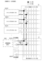
- FIGS. 2 to 4 are diagrams showing an example of string connection and an example of the on/off state of each switch of the switching unit 30 in that case.
- a black circle in the switching unit 30 indicates an on (closed) switch
- a white circle indicates an off (open) switch.
- the current flow between the string 20 and the power supply unit 50 is indicated by a thick black line.
- the charging control device 40 and other components are not shown in the figures.
- FIG. 2 shows an example of an individual connection. Of the strings 20 in the solar cell array 10, FIG. 2 shows three strings 20A to 20C with different combinations of generated voltage and generated current.
- a power storage device 9A with a voltage specification of 500V is connected to a first power supply unit 50A.
- one string 20 with a voltage specification closest to that of the power storage device 9 is connected to the power supply unit 50 to which the power storage device 9 is connected.
- string 20A whose generated voltage is 500V, the closest to (in this case, the same as) the voltage specification of 500V for power storage device 9A, is connected (individually connected) to first power supply section 50A to which power storage device 9A is connected. That is, the positive pole (+) of string 20A is connected to the positive pole (+) of first power supply section 50A, and the negative pole (-) of string 20A is connected to the negative pole (-) of first power supply section 50A.
- the switching control of switching section 30 is performed by turning on (closing) switches Q1 and Q2 of string connection switching section 32 to make the string connection of string 20A an individual connection, and turning on (closing) switches Q3 and Q4 of the power supply destination switching section to connect first power supply section 50A as the power supply destination of the individual connection.
- the DC/DC converter 42 corresponding to the first power supply unit 50A has its voltage transformation operation controlled by the charging control device 40, and outputs the charging power to the power storage device 9A. At this time, the voltage input to the DC/DC converter 42 and the voltage output from the DC/DC converter 42 are approximately the same voltage. Therefore, the voltage transformation in the DC/DC converter 42 is realized with high efficiency.
- FIG. 3 shows an example of a parallel connection.
- FIG. 3 shows three strings 20A to 20C of the strings 20 of the solar cell array 10, each having a different combination of generated voltage and generated current.
- a storage battery 9B with a voltage specification of 500V is connected to the first power supply unit 50A.
- the multiple strings 20 whose generated voltage is closest to the voltage specification of the storage battery 9 are connected in parallel to the power supply unit 50 to which the storage battery 9 is connected.
- two strings 20A, 20B whose generated voltage is 500V, the closest to (in this case, the same as) the voltage specification of the storage device 9B, are connected in parallel (parallel connection) to the first power supply section 50A to which the storage device 9B is connected. That is, the positive poles (+) of the strings 20A, 20B are connected to the positive pole (+) of the first power supply section 50A, and the negative poles (-) of the strings 20A, 20B are connected to the negative pole (-) of the first power supply section 50A.
- the switching control of the switching section 30 is performed by turning on (closing) the switches Q1, Q2, Q5, and Q6 of the string connection switching section 32 to connect the strings 20A and 20B in parallel, and turning on (closing) the switches Q3 and Q4 of the power supply destination switching section to make the first power supply section 50A the power supply destination of the parallel connection.
- the individual connection in Figure 2 and the parallel connection in Figure 3 have the same charging voltage of 500V, but the charging current is different.
- the parallel connection in Figure 3 can obtain a larger charging current.
- FIG. 4 shows an example of a series connection.
- FIG. 4 shows three strings 20A to 20C of the strings 20 of the solar cell array 10, each having a different combination of generated voltage and generated current.
- a storage battery 9C with a voltage specification of 1250V is connected to the first power supply unit 50A.
- the sum of the generated voltages of the strings 20 is closest to the voltage specification of the storage battery 9, and multiple strings 20 whose generated currents are approximately the same are connected in series to the power supply unit 50 to which the storage battery 9 is connected.
- strings 20A and 20C are connected in series (series connection). Since the generated voltage of string 20A is 500V and the generated voltage of string 20C is 750V, the total of 1250V is closest to (in this case, coincides with) the voltage specification (optimum charging voltage) of storage device 9C. In addition, both strings 20A and 20C have a generated current of 10A. Therefore, strings 20A and 20C are connected in series. In other words, the positive pole (+) of string 20A is connected to the negative pole (-) of string 20C, the positive pole (+) of string 20C is connected to the positive pole (+) of first power supply unit 50A, and the negative pole (-) of string 20A is connected to the negative pole (-) of first power supply unit 50A.
- the switching control of the switching unit 30 is performed by turning on (closing) the switches Q1, Q2, Q7, and Q8 of the string connection switching unit 32 to connect strings 20A and 20C in series, and turning on (closing) the switches Q3 and Q9 of the power supply destination switching unit to make the first power supply unit 50A the power supply destination of the series connection.
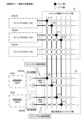
- FIGS. 5 and 6 show an example of dynamic control of the switching unit 30 according to the charging status of the storage device 9. As with the example of FIG. 2, FIGS. 5 and 6 show three strings 20A to 20C of the strings 20 of the solar cell array 10, each of which has different combinations of generated voltage and generated current.
- two storage devices 9D and 9E are charged simultaneously. That is, storage device 9D with a voltage specification of 500V is connected to first power supply section 50A, and storage device 9E with a voltage specification of 500V is connected to second power supply section 50B. Then, string 20A with a generation voltage of 500V close to the voltage specification of storage device 9D is individually connected to first power supply section 50A to which storage device 9D is connected. That is, the positive terminal (+) of string 20A is connected to the positive terminal (+) of first power supply section 50A, and the negative terminal (-) of string 20A is connected to the negative terminal (-) of first power supply section 50A.
- string 20B with a generation voltage of 500V close to the voltage specification of storage device 9E is individually connected to second power supply section 50B to which storage device 9E is connected.
- the positive pole (+) of string 20B is connected to the positive pole (+) of second power supply unit 50B
- the negative pole (-) of string 20B is connected to the negative pole (-) of second power supply unit 50B.
- the controller 60 constantly acquires and monitors the charging status of each of the two storage devices 9. For example, when charging of one of the storage devices 9 is completed first (reaches a predetermined charging status of full charge), the controller 60 controls the switching unit 30 to dynamically switch the string connection as shown in FIG. 6.
- the switches Q13 and Q14 of the power supply destination switching unit 34 are turned off (opened) and the switches Q11 and Q12 of the string connection switching unit 32 are turned off (opened) so as to disconnect the second power supply unit 50B to which the power storage device 9E is connected from the string 20B.
- the generated voltage of the disconnected string 20B is approximately the same as that of the string 20A supplying charging power to the first power supply unit 50A to which the storage device 9D is connected. Therefore, string 20B is added as a new string that supplies (feeds) charging power to the first power supply unit 50A (the first power supply unit becomes the new power supply destination of string 20B). Specifically, switches Q5 and Q6 of the string connection switching unit 32 are turned on (closed) so that the string connection connected to the first power supply unit 50A is switched to a parallel connection of strings 20A and 20B.
- two strings 20A and 20B whose generated voltage is 500V, close to (in this case, identical to) the voltage specification of 500V for the storage device 9D, are connected in parallel (parallel connection) to the first power supply section 50A to which the storage device 9D is connected.
- the positive terminals (+) of strings 20A and 20B are connected to the positive terminal (+) of the first power supply section 50A
- the negative terminals (-) of strings 20A and 20B are connected to the negative terminal (-) of the first power supply section 50A.
- the charging current to the storage device 9D is 35A, which is the sum of the generated currents of the connected strings 20A and 20B.
- ⁇ Controller> 7 is a diagram showing an example of the configuration of the controller 60.
- the controller 60 is realized as a type of computer system, and includes an input unit 102, a communication unit 104, a display unit 106, a sound emitting unit 108, a control unit 200, and a storage unit 300.
- the input unit 102 is realized as an input device or an input interface such as a button switch, a keyboard, or a touch panel formed integrally with a display, which accepts operational input from an operator.
- the communication unit 104 is realized as a wireless communication device or a wireless communication device or a communication interface thereof for communicating with an external device.
- the display unit 106 is realized as a lamp, a display, etc.
- the sound emission unit 108 is realized as a speaker, etc.
- the control unit 200 is realized by an arithmetic circuit equipped with processors such as a CPU (Central Processing Unit), MPU (Micro-Processing Unit), and DSP (Digital Signal Processor).
- processors such as a CPU (Central Processing Unit), MPU (Micro-Processing Unit), and DSP (Digital Signal Processor).
- control unit 200 may be provided by an ASIC (Application Specific Integrated Circuit), a GPU (Graphics Processing Unit), etc., or may be realized by hardware circuits such as an FPGA (Field-Programmable Gate Array) or a dedicated LSI (Large Scale Integration).
- ASIC Application Specific Integrated Circuit
- GPU Graphics Processing Unit
- hardware circuits such as an FPGA (Field-Programmable Gate Array) or a dedicated LSI (Large Scale Integration).
- the control unit 200 has, as its functional units, a switching control unit 202, a specification data acquisition unit 204, and a charging status acquisition unit 206.
- the switching control unit 202 controls the power supply destination switching unit 34 and the string connection switching unit 32 based on the power supply unit 50 to which the power storage device 9 is connected among the M power supply units 50.
- the string connection switching unit 32 can switch between an individual connection in which the strings 20 are individually connected to the power supply destination, a parallel connection in which the strings 20 are connected in parallel, and a series connection in which the strings 20 are connected in series (see Figures 2 to 4).
- power storage devices 9 with different specifications can be connected to the power supply unit 50, and the switching control unit 202 controls the string connection switching unit 32 based on the specification data of the power storage device 9 connected to the power supply unit 50.
- the specification data of the power storage device 9 is acquired by the specification data acquisition unit 204.
- the specification data acquisition unit 204 can acquire the specification data, for example, by an operation input performed by an operator via the input unit 102.
- a reading device 50a that reads the specification data of the power storage device 9 from the BMS 9a of the power storage device 9 or an IC tag 9b provided on the power storage device 9 may be provided in the power supply unit 50, and the specification data read by the reading device 50a may be output (by wired communication or wireless communication) to the controller 60, so that the specification data acquisition unit 204 acquires the data.
- the acquired specification data of the power storage device 9 is stored as connected power storage device data 306.
- FIG. 8 is an example of connected power storage device data 306.
- the connected power storage device data 306 stores the specifications (voltage, capacity, etc.) of the connected power storage device 9 for each of the M power supply units 50 in association with each other.
- the N strings 20 also include strings 20 with different power generation specifications related to the generated voltage and generated current, and the switching control unit 202 controls the string connection switching unit 32 based on the specification data of the storage device 9 connected to the power supply unit 50 and the power generation specifications of the strings 20.
- the power generation specifications of the strings 20 are prepared in advance as solar cell array configuration data 302.
- Figure 9 is an example of the solar cell array configuration data 302.
- the solar cell array configuration data 302 stores power generation specifications such as the power generation voltage and power generation current for each of the N strings 20 in the solar cell array 10.
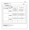
- the switching control unit 202 controls the power supply destination switching unit 34 and the string connection switching unit 32 (turning the switches on and off) according to the connection relationship definition table 304.
- connection relationship definition table 304 is an example of the connection relationship definition table 304.
- the "switch to be turned on” is determined by the number of power supply units 50 (connected to the power storage devices 9) that supply power simultaneously, the voltage specifications of the power storage devices 9 connected to the power supply units 50, and the power generation specifications of the strings 20. Since the power generation specifications of the strings 20 are fixed, the connection relationship definition table 304 defines the "switch to be turned on” in association with each combination of the number of power supply units 50 that supply power simultaneously and the voltage specifications of the power storage devices 9 connected to the power supply units 50.
- the number of string connections (number and combination of strings) that can supply charging power to a power supply unit 50 to which a power storage device 9 of a certain voltage specification is connected is not limited to one, but may be multiple.
- all combinations of switches that are turned on to realize these multiple string connections may be stored, or only those that satisfy predetermined conditions such as the charging current, the number of strings to be connected, or a specific string may be stored.
- the switching control unit 202 also dynamically controls the power supply destination switching unit 34 and the string connection switching unit 32 based on the charging status of the power storage device 9 connected to the power supply unit 50.
- the charging status of the power storage device 9 is acquired by the charging status acquisition unit 206.
- the charging status acquisition unit 206 can acquire the charging status of the power storage device 9 by calculating it based on, for example, the output voltage and output current of the DC/DC converter 42 output by the charging control device 40 to the controller 60.
- the charging status may be acquired by having the reading device 50a read the charging status from the BMS 9a.
- the charging status may be, for example, a charging rate or a State of Charge (SoC).
- the switching control unit 202 dynamically controls based on the charging status. For example, when the storage device 9 reaches a predetermined charging status, such as full charge or a charging rate of 90%, it controls the switching unit 30 to disconnect the string 20 that was connected to the power supply unit 50 to which the storage device 9 is connected, and supplies power to that string 20. It also controls the switching unit 30 to supply power to a power supply unit 50 to which another storage device 9 that has not yet reached the predetermined charging status is connected (see Figures 5 and 6).
- a predetermined charging status such as full charge or a charging rate of 90%
- the memory unit 300 is realized by a flash memory, a ROM (Read Only Memory), a RAM (Random Access Memory), a HDD (Hard Disk Drive), an SSD (Solid State Drive), an EPROM (Erasable Programmable ROM), etc.
- the memory unit 300 stores solar cell array configuration data 302, a connection relationship definition table 304, and connected energy storage device data 306.
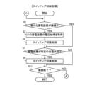
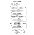
- ⁇ Processing flow> 11 is a flowchart of a switching control process executed by the controller 60.
- the initial state is a state in which the power storage device 9 is not connected to any of the power supply units 50.
- the specification data acquisition unit 204 acquires the specification data of the storage device 9 (step S3).
- the specification data acquisition unit 204 may constantly attempt to acquire the specification data, and when the acquisition of the specification data is successful, detect that a new storage device 5 is connected to the power supply unit 50.
- the switching control unit 202 performs control to switch the switch of the switching unit 30 on/off so that the power supply unit 50 to which the storage device 9 is connected is supplied with charging power according to the voltage specification of the storage device 9 based on the acquired specification data, which power supply unit 50 the storage device 9 is connected to, and the voltage specification of the connected storage device 9 (step S5).
- the switching control is performed according to a predetermined connection relationship definition table 304 based on the number of power supply units 50 to which the storage device 9 is connected and the voltage specification of the storage device 9.
- the switching control unit 202 controls the switching unit 30 to switch on/off according to the charging status (step S9). For example, when the predetermined charging status is full charge (charging completed), the string 20 that was supplied with power from the power supply unit 50 to which the fully charged power storage device 9 is connected is disconnected, and the supply of charging power is terminated. Then, if necessary, the switching unit 30 is controlled so that the new power supply destination of the string 20 is another power supply unit 50. The switching control is performed according to a predetermined connection relationship definition table 304 based on the number of power supply units 50 to which the power storage device 9 is connected and the voltage specifications of the power storage device 9.
- a predetermined charging status for example, full charge or a charging rate of 90%
- step S11 NO
- step S11 YES
- the power generation status (power generation voltage and power generation current) of the string 20 is fixed (matching the power generation specifications (power generation voltage and power generation current) determined by the configuration).
- the power generation status (charging voltage and power generation current) of the string 20 can change dynamically.
- the switching unit 30 is dynamically controlled according to such changes in the power generation status (power generation voltage and power generation current) of the string 20.
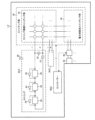
- Fig. 12 is a configuration diagram of a photovoltaic power generation system 1 ⁇ in the second embodiment.
- the main difference from the photovoltaic power generation system 1 in the first embodiment (see Fig. 1) is that a bypass diode 24 is provided for each module or cluster 22 consisting of a plurality of modules in the string 20 ⁇ .
- the bypass diode 24 is connected in parallel with the cluster 22, and operates to serve as a detour for the generated current when the cluster 22 is unable or has difficulty generating power due to a decrease in solar radiation caused by shading or a failure of a solar cell.
- the controller 60 ⁇ acquires the power generation status of the string 20 ⁇ from the operating state of the bypass diodes 24.
- the operating state of the bypass diodes 24 can be acquired, for example, by providing a current sensor 26 that detects the current through the bypass diodes 24 and a communication device 28 that outputs (by wired or wireless communication) the detection result (presence or absence of current) to the controller 60, and having the communication device 28 output (by wired or wireless communication).
- the power generation status of string 20 ⁇ can be calculated by determining the number of modules capable of generating power from the operating state of bypass diodes 24, and multiplying the number of modules by the power generation specifications (generated voltage) per module, since string 20 ⁇ is composed of multiple modules connected in series. Note that the generated current is determined by the power generation specifications (generated current) per module, regardless of the number of modules capable of generating power, since the modules are connected in series. Controller 60 ⁇ then controls switching unit 30 based on the calculated power generation status (generated voltage and generated current) of string 20 ⁇ and the voltage specifications of the storage device 9 connected to power supply unit 50.
- connection relationship of the string 20 ⁇ to be connected to the power supply unit 50 is determined based on the power generation status (power generation voltage and power generation current) of the string 20 ⁇ so as to satisfy the voltage specifications of the connected storage device 9.
- the connection relationship of the string 20 ⁇ refers to the string connection, and includes the number and combination of the strings 20 ⁇ , and the connection pattern such as individual, series, and parallel.
- the string connection is such that one string 20 ⁇ is not connected to multiple power supply units 50 (is not used as a power supply destination). Note that there may be more than one string connection capable of supplying charging power to a power supply unit 50 to which a storage device 9 with a certain voltage specification is connected.
- the switching unit 30 is controlled to realize the determined string connection.
- the control of the switching unit 30 can be performed, for example, according to a connection relationship definition table 304 ⁇ , an example of which is shown in FIG. 13.
- FIG. 13 is an example of a connection relationship definition table 304 ⁇ .
- table 304 ⁇ -m one or more corresponding strings 20 ⁇ and "switches to turn on" are defined for each combination of the number of strings (number of strings 20 ⁇ to be connected) and pattern (distinguishing between individual, parallel, and series connections) connected to the power supply unit 50.
- ⁇ Controller> 14 is a diagram showing an example of the configuration of the controller 60 ⁇ .
- the controller 60 ⁇ is realized as a type of computer system, and includes a control unit 200 ⁇ , a storage unit 300 ⁇ , an input unit 102, a communication unit 104, a display unit 106, and a sound emission unit 108.
- the control unit 200 ⁇ has a switching control unit 202 ⁇ , a specification data acquisition unit 204, a charging status acquisition unit 206, and a bypass diode operation status acquisition unit 208.
- the switching control unit 202 ⁇ dynamically controls the string connection switching unit 32 based on the specification data of the storage device 9 connected to the power supply unit 50, the power generation specifications of the string 20 ⁇ , and the operating state of the bypass diode 24.
- the operation state of the bypass diode 24 is acquired by the bypass diode operation state acquisition unit 208.
- the bypass diode operation state acquisition unit 208 acquires the operation state of the bypass diode 24, for example, by acquiring the detection result (presence or absence of current) from the current sensor 26 that detects the current flow through the bypass diode 24 via the communication device 28.
- the switching control unit 202 ⁇ determines the number of modules capable of generating power for each string 20 ⁇ from the operating state of the bypass diodes 24, and calculates the power generation status (generated voltage) of the string 20 ⁇ by multiplying the power generation specifications (generated voltage) per module by the number of modules. Since the modules are connected in series, the generated current can be determined based on the power generation specifications (generated current) of each module, regardless of the number of modules that can generate power. However, the generated current may be determined by reducing the amount of current depending on the number of modules that cannot generate power.
- the configuration of the string 20 ⁇ including the bypass diodes 24 is prepared and stored in advance as solar cell array configuration data 302 ⁇ .
- FIG. 15 is an example of the solar cell array configuration data 302 ⁇ .
- the solar cell array configuration data 302 ⁇ stores the cluster ID of each cluster 22 to which the bypass diodes 24 are connected in parallel, the number of modules constituting the cluster 22, and the bypass diode ID of the bypass diode 24 provided in the cluster 22, in association with each other.
- the power generation status of string 20 ⁇ is appropriately updated and stored as power generation status data 310.
- FIG. 16 is an example of power generation status data 310.
- the power generation status data 310 stores the current power generation status (power generation voltage and power generation current) for each string 20 ⁇ in association with each other.
- the power generation specifications (power generation voltage and power generation current) for each module are prepared and stored in advance as unit power generation specification data 308.
- the switching control unit 202 ⁇ determines the connection relationship of the string 20 ⁇ to be connected to the power supply unit 50 so as to satisfy the voltage specifications of the connected storage device 9 based on the power generation status (power generation voltage and power generation current) of the string 20 ⁇ .
- the connection relationship of the string 20 ⁇ refers to the string connection, including the number and combination of the strings 20 ⁇ , and the connection pattern such as individual, series, or parallel. Then, the switching unit 30 is controlled according to the connection relationship definition table 304 ⁇ (see FIG. 13) so as to realize the determined string connection.
- the memory unit 300 ⁇ stores solar cell array configuration data 302 ⁇ , unit power generation specification data 308, a connection relationship definition table 304 ⁇ , connected power storage device data 306, and power generation status data 310.
- ⁇ Processing flow> 17 and 18 are flowcharts of the processes executed by the controller 60 ⁇ .
- the controller 60 ⁇ performs the power generation status determination process shown in Fig. 17 and the switching control process shown in Fig. 18 in parallel.
- the initial state is a state in which the power storage device 9 is not connected to any of the power supply units 50.
- the bypass diode operation status acquisition unit 208 acquires the operation status of each bypass diode 24 (step S23). Then, based on the acquired operation status of the bypass diodes 24, the power generation status of each string 20 ⁇ is determined and the power generation status data 310 is updated (step S25).
- the power generation status determination timing can be set to arrive at a predetermined time interval, such as every 5 minutes or every 10 minutes.
- step S27: NO the process returns to step S21 and repeats the same process. If it is to end (step S27: YES), this process ends.
- the specification data acquisition unit 204 acquires the specification data of the connected storage device 9 (step S3). Then, based on the specification data, the switching control unit 202 ⁇ controls the on/off switching of the switching unit 30 so that the power supply unit 50 to which the newly connected storage device 9 is supplied with charging power according to the voltage specification of the storage device 9 (step S5).
- the switching control is performed according to the connection relationship definition table 304 ⁇ based on the number of power supply units 50 to which the storage devices 9 are connected, the voltage specification of the storage device 9, and the power generation status of the string 20 ⁇ .
- the switching control unit 202 ⁇ controls the switching unit 30 to switch on/off according to the charging status (step S9).
- the switching control unit 202 ⁇ controls the switching unit 30 to switch on/off so as to switch to a string connection according to the new power generation status after the update (step S33).
- the switching control is performed according to the connection relationship definition table 304 ⁇ based on the number of power supply units 50 to which the power storage devices 9 are connected, the voltage specifications of the power storage devices 9, and the power generation status of the strings 20.
- step S35 NO
- step S35 YES
- the photovoltaic power generation system 1 includes a plurality of (M) power supply units 50 that can be electrically connected to the storage device 9, and thus M or less storage devices can be arbitrarily replaced and connected.
- the string connection which is the connection relationship of the strings to be connected, can be switched by the control of the switching unit 30 by the controller 60. This makes it possible to switch to an appropriate string connection according to the connected storage device 9. Therefore, it becomes possible to appropriately charge a plurality of replaceable storage devices 9. For example, by configuring the string connection so as to output a voltage that matches the specifications of the connected storage device 9, it becomes possible to suppress the conversion loss in the DC/DC converter 42 as much as possible, and it becomes possible to realize more efficient charging. If there are a plurality of connected storage devices 9, it is also possible to configure the string connection so as to charge them in parallel, or to configure the string connection so as to preferentially allocate charging power to the storage device 9 that is desired to be charged early.
- various voltages and currents of power can be supplied as charging power to the power supply unit 50, which is the power supply destination.
- This enables appropriate charging control according to the specifications of the storage device 9, such as the capacity and voltage (rated voltage and voltage range).
- the string connection switching unit 32 by dynamically controlling the string connection switching unit 32 based on the operating state of the bypass diode 24, it is possible to dynamically switch the string connection connected to the power supply unit 50 to which the power is supplied.
- This enables more appropriate charging control of the power storage device 9.
- the power generation status related to the generated voltage and generated current of the string 20 ⁇ may change due to changes in solar radiation due to shading, adhesion of dust, etc., or failure of the solar cell.
- the power generation status (generated voltage and generated current) of string 20 ⁇ is determined based on the acquired operating state of the bypass diodes 24.
- a power generation status acquisition unit may be provided that acquires the power generation status related to the generated voltage and generated current of each of the N strings 20 ⁇ , and the switching control unit 202 ⁇ may control the string connection switching unit 32 based on the specification data of the storage device 9 connected to the power supply unit 50 and the power generation specifications of string 20 ⁇ acquired by the power generation status acquisition unit.
- each string 20 ⁇ is provided with a voltmeter 25 that measures the generated voltage, which is the output voltage, an ammeter 27 that measures the generated current, which is the output current, and a communication device 29 that outputs (wired or wireless communication) these measured values (generated voltage and generated current) to controller 60 ⁇ . Then, by acquiring the measured generated voltage and generated current from communication device 29, a power generation status acquisition unit can be realized.
- a communication device may be provided for each switch of the switching unit 30, and the operating state of the switch (such as the on/off state and the execution of the switching operation) may be output (by wired communication or wireless communication) to the controllers 60, 60 ⁇ .
- the controllers 60, 60 ⁇ determine whether each switch is normal or not based on the operating state of the switch acquired from these communication devices, and control the switching unit 30 so as to use only the switches determined to be normal. This enables more appropriate charging control of the storage device 9.
- the communication device provided in each switch can be, for example, a wireless communication device that complies with the Wi-SUN (Wireless Smart Utility Network) standard, which is a specific low-power wireless standard.
- Wi-SUN Wireless Smart Utility Network
- the Wi-SUN standard allows long-distance communication with very little power consumption and supports multi-hop communication, making it suitable as a communication device to be provided in a switching unit 30 that has many switches.
- the communication device 28 in the solar power generation system 1 ⁇ of the second embodiment can be a wireless communication device that complies with this Wi-SUN standard.
- charging of the power storage device 9 by the power supply unit 50 may be achieved by wireless power supply.
- a solar power generation system in which a power storage device that is charged with power generated by solar power generation is configured to be replaceable, N strings (N ⁇ 2); M (M ⁇ 2) power supply units electrically connectable to the power storage device; M DC/DC converters provided for each of the power supply units for supplying charging power to a power storage device connected to the power supply unit; a switching unit capable of switching a connection relationship between each of the strings and each of the DC/DC converters; A controller that controls the switching unit; Equipped with The switching unit is a power supply destination switching unit that switches a DC/DC converter to which power is supplied among the M DC/DC converters; a string connection switching unit that switches a string connection, which is a connection relationship of the strings that are connected to the power supply destination; having The controller controls the power supply destination switching unit and the string connection switching unit based on a power supply unit to which the power storage device is connected among the M power supply units.
- the string connection switching unit switches between an individual connection in which the strings are individually connected to the power supply destination, a parallel connection in which the strings are connected in parallel, and a series connection in which the strings are connected in series.
- a solar power generation system according to a first invention.
- the power storage device having a different voltage specification can be connected to the power supply unit, a voltage specification data acquisition unit that acquires voltage specification data of the power storage device connected to the power supply unit; Further comprising: The controller controls the string connection switching unit based on voltage specification data of the power storage device connected to the power supply unit.
- the N strings include strings with different power generation specifications related to a power generation voltage and a power generation current
- the controller controls the string connection switching unit based on voltage specification data of the power storage device connected to the power supply unit and power generation specifications of the string.
- a solar power generation system according to any one of the first to third aspects of the present invention.
- the string is configured by connecting photovoltaic power generation modules in series, and connecting a bypass diode to each of the modules or each of the clusters constituting the modules, a bypass diode operation state acquisition unit that acquires an operation state of the bypass diode; Further comprising: The controller dynamically controls the string connection switching unit based on voltage specification data of the power storage device connected to the power supply unit, power generation specifications of the string, and the operation state acquired by the bypass diode operation state acquisition unit.
- a solar power generation system according to any one of the first to fourth inventions.
- a power generation status acquisition unit that acquires a power generation status related to a generated voltage and a generated current of each of the N strings; Further comprising: The controller dynamically controls the string connection switching unit based on voltage specification data of the power storage device connected to the power supply unit and the power generation status of each string acquired by the power generation status acquisition unit.
- the controller dynamically controls the string connection switching unit based on voltage specification data of the power storage device connected to the power supply unit and the power generation status of each string acquired by the power generation status acquisition unit.
- a charging status acquisition unit that acquires a charging status of the power storage device connected to the power supply unit; Further comprising: The controller dynamically controls the power supply destination switching unit and the string connection switching unit based on the charging status.
- the solar power generation system includes: N strings (N ⁇ 2); M (M ⁇ 2) power supply units electrically connectable to the power storage device; M DC/DC converters provided for each of the power supply units for supplying charging power to a power storage device connected to the power supply unit; a switching unit capable of switching a connection relationship between each of the strings and each of the DC/DC converters; Equipped with The switching unit is a power supply destination switching unit that switches a DC/DC converter to which power is supplied among the M DC/DC converters; a string connection switching unit that switches a string connection, which is a connection relationship of the strings that are connected to the power supply destination; It has controlling the power supply destination switching unit and the string connection switching unit based on a power supply unit to which the power storage device is connected among the M power supply units; Control methods.
Landscapes
- Engineering & Computer Science (AREA)
- Power Engineering (AREA)
- Charge And Discharge Circuits For Batteries Or The Like (AREA)
Priority Applications (1)
| Application Number | Priority Date | Filing Date | Title |
|---|---|---|---|
| JP2024557410A JPWO2024101334A1 (https=) | 2022-11-10 | 2023-11-07 |
Applications Claiming Priority (2)
| Application Number | Priority Date | Filing Date | Title |
|---|---|---|---|
| JP2022-180151 | 2022-11-10 | ||
| JP2022180151 | 2022-11-10 |
Publications (1)
| Publication Number | Publication Date |
|---|---|
| WO2024101334A1 true WO2024101334A1 (ja) | 2024-05-16 |
Family
ID=91032410
Family Applications (1)
| Application Number | Title | Priority Date | Filing Date |
|---|---|---|---|
| PCT/JP2023/039976 Ceased WO2024101334A1 (ja) | 2022-11-10 | 2023-11-07 | 太陽光発電システムおよび制御方法 |
Country Status (2)
| Country | Link |
|---|---|
| JP (1) | JPWO2024101334A1 (https=) |
| WO (1) | WO2024101334A1 (https=) |
Citations (4)
| Publication number | Priority date | Publication date | Assignee | Title |
|---|---|---|---|---|
| JP2005160290A (ja) * | 2003-10-30 | 2005-06-16 | Sharp Corp | 独立電源システム |
| WO2011052407A1 (ja) * | 2009-10-29 | 2011-05-05 | 三洋電機株式会社 | 切替回路、制御装置および発電システム |
| US20220029211A1 (en) * | 2018-12-14 | 2022-01-27 | Robert Bosch Gmbh | Energy store for an electrically drivable means of transportation |
| WO2023203871A1 (ja) * | 2022-04-21 | 2023-10-26 | 株式会社日立製作所 | 直流充電装置 |
-
2023
- 2023-11-07 WO PCT/JP2023/039976 patent/WO2024101334A1/ja not_active Ceased
- 2023-11-07 JP JP2024557410A patent/JPWO2024101334A1/ja active Pending
Patent Citations (4)
| Publication number | Priority date | Publication date | Assignee | Title |
|---|---|---|---|---|
| JP2005160290A (ja) * | 2003-10-30 | 2005-06-16 | Sharp Corp | 独立電源システム |
| WO2011052407A1 (ja) * | 2009-10-29 | 2011-05-05 | 三洋電機株式会社 | 切替回路、制御装置および発電システム |
| US20220029211A1 (en) * | 2018-12-14 | 2022-01-27 | Robert Bosch Gmbh | Energy store for an electrically drivable means of transportation |
| WO2023203871A1 (ja) * | 2022-04-21 | 2023-10-26 | 株式会社日立製作所 | 直流充電装置 |
Also Published As
| Publication number | Publication date |
|---|---|
| JPWO2024101334A1 (https=) | 2024-05-16 |
Similar Documents
| Publication | Publication Date | Title |
|---|---|---|
| CN102097821B (zh) | 并网能量存储系统以及控制并网能量存储系统的方法 | |
| US8648496B2 (en) | Reconfigurable microgrid direct current interface | |
| JP5959561B2 (ja) | 直列接続された複数の電池直流マイクログリッド充放電システム | |
| CN107534298A (zh) | 用于pv串、电池、电网及备用负载的混合逆变器电力控制系统 | |
| US8536734B2 (en) | Apparatus for inverting DC voltage to AC voltage | |
| CN110116645A (zh) | 充电系统以及给电动车辆充电的方法 | |
| US9035496B2 (en) | Power control system and controlling method thereof | |
| CN102655342A (zh) | 电源系统 | |
| CN111224402A (zh) | 直流多微电网系统及控制方法 | |
| CN105075054B (zh) | 电力转换装置、控制系统和控制方法 | |
| CN106684958A (zh) | 电池系统与其控制方法 | |
| CN113162106A (zh) | 一种储能系统及一种光伏储能系统 | |
| CN114467238A (zh) | 连接至多个电力总线的储能器 | |
| CN105379048A (zh) | 电力转换装置、电力转换系统以及电力转换方法 | |
| CN114846716A (zh) | 控制能量存储器的能量模块的接通时间 | |
| CN107516893A (zh) | 能量路由器及基于该能量路由器的发电控制方法 | |
| JP2021119727A (ja) | 分散型電源システムおよび分散型電源装置 | |
| JP2019193475A (ja) | 蓄電装置、蓄電装置の制御装置及び蓄電装置の制御方法 | |
| KR102806353B1 (ko) | 비상전원 공급 기능을 가지는 에너지 저장 시스템 및 그것의 제어 방법 | |
| WO2024101334A1 (ja) | 太陽光発電システムおよび制御方法 | |
| CN112366738B (zh) | 一种保障电梯供电的微电网蓄电控制系统 | |
| WO2024101335A1 (ja) | 充電制御装置および制御方法 | |
| CN109861200A (zh) | 离网黑启动的光储直流电网系统及其运行方法 | |
| CN111406352A (zh) | 储能系统 | |
| CN106981917A (zh) | 一种组合式直流供电系统 |
Legal Events
| Date | Code | Title | Description |
|---|---|---|---|
| 121 | Ep: the epo has been informed by wipo that ep was designated in this application |
Ref document number: 23888681 Country of ref document: EP Kind code of ref document: A1 |
|
| WWE | Wipo information: entry into national phase |
Ref document number: 2024557410 Country of ref document: JP |
|
| NENP | Non-entry into the national phase |
Ref country code: DE |
|
| 122 | Ep: pct application non-entry in european phase |
Ref document number: 23888681 Country of ref document: EP Kind code of ref document: A1 |