WO2024101320A1 - 測定方法、測定システム、およびプログラム - Google Patents
測定方法、測定システム、およびプログラム Download PDFInfo
- Publication number
- WO2024101320A1 WO2024101320A1 PCT/JP2023/039926 JP2023039926W WO2024101320A1 WO 2024101320 A1 WO2024101320 A1 WO 2024101320A1 JP 2023039926 W JP2023039926 W JP 2023039926W WO 2024101320 A1 WO2024101320 A1 WO 2024101320A1
- Authority
- WO
- WIPO (PCT)
- Prior art keywords
- measurement
- electrodes
- electric field
- measuring
- sample
- Prior art date
- Legal status (The legal status is an assumption and is not a legal conclusion. Google has not performed a legal analysis and makes no representation as to the accuracy of the status listed.)
- Ceased
Links
Images





Classifications
-
- G—PHYSICS
- G01—MEASURING; TESTING
- G01N—INVESTIGATING OR ANALYSING MATERIALS BY DETERMINING THEIR CHEMICAL OR PHYSICAL PROPERTIES
- G01N27/00—Investigating or analysing materials by the use of electric, electrochemical, or magnetic means
-
- G—PHYSICS
- G01—MEASURING; TESTING
- G01N—INVESTIGATING OR ANALYSING MATERIALS BY DETERMINING THEIR CHEMICAL OR PHYSICAL PROPERTIES
- G01N27/00—Investigating or analysing materials by the use of electric, electrochemical, or magnetic means
- G01N27/02—Investigating or analysing materials by the use of electric, electrochemical, or magnetic means by investigating impedance
- G01N27/22—Investigating or analysing materials by the use of electric, electrochemical, or magnetic means by investigating impedance by investigating capacitance
-
- G—PHYSICS
- G01—MEASURING; TESTING
- G01R—MEASURING ELECTRIC VARIABLES; MEASURING MAGNETIC VARIABLES
- G01R27/00—Arrangements for measuring resistance, reactance, impedance, or electric characteristics derived therefrom
- G01R27/02—Measuring real or complex resistance, reactance, impedance, or other two-pole characteristics derived therefrom, e.g. time constant
- G01R27/26—Measuring inductance or capacitance; Measuring quality factor, e.g. by using the resonance method; Measuring loss factor; Measuring dielectric constants ; Measuring impedance or related variables
Definitions
- the present invention relates to a measurement method, a measurement system, and a program.
- a lubricant e.g., lubricating oil or grease
- the lubrication state is monitored to detect damage and wear early and prevent the occurrence of failures of rotating parts.
- Patent Document 1 discloses a method that makes it possible to easily diagnose the state of the lubricant without destroying the object to be diagnosed.
- Patent Document 1 shows a configuration that uses impedance analysis using parallel plate electrodes. However, depending on the location where the lubrication state is monitored, the state may differ from that of the parallel plates. It is also conceivable that the amount of sample whose state is to be measured may be extremely small. Therefore, there is a demand for a method of measuring a sample that can handle such conditions.
- the present invention aims to provide a method that can measure the state of a minute amount of sample with high accuracy.
- a measurement method comprising the steps of: a measuring step of measuring impedance by applying a predetermined voltage to a measurement target via a measuring unit including an electrode having a predetermined shape and a substrate on which the electrode is formed; a derivation step of deriving a complex dielectric constant of the object to be measured by inputting a measurement result from the measurement step into a predetermined calculation formula defined based on an equivalent circuit corresponding to a configuration of the measurement unit and the object to be measured; having the equivalent circuit is defined in correspondence with an electric field between the electrodes in the measurement unit, an electric field on a substrate side of the electrodes, and an electric field on the measurement target side of the electrodes;
- the predetermined calculation formula is defined to include parameters based on the measurement results of a standard sample and a background sample by the measurement unit.
- a measurement system comprising: A measuring unit including an electrode having a predetermined shape and a substrate on which the electrode is formed; A power supply unit that supplies a predetermined voltage; a measuring means for measuring impedance by applying a predetermined voltage from the power supply unit to a measurement target via the measuring unit; a derivation means for deriving a complex dielectric constant of the object to be measured by inputting a measurement result by the measurement means into a predetermined calculation formula defined based on an equivalent circuit corresponding to a configuration of the measurement unit and the object to be measured; having the equivalent circuit is defined in correspondence with an electric field between the electrodes in the measurement unit, an electric field on a substrate side of the electrodes, and an electric field on the measurement target side of the electrodes;
- the predetermined calculation formula is defined to include parameters based on the measurement results of a standard sample and a background sample by the measurement unit.
- a program comprising: On the computer, a measuring step of measuring impedance by applying a predetermined voltage to a measurement target via a measuring unit including an electrode having a predetermined shape and a substrate on which the electrode is formed; a derivation step of deriving a complex dielectric constant of the object to be measured by inputting a measurement result from the measurement step into a predetermined calculation formula defined based on an equivalent circuit corresponding to a configuration of the measurement unit and the object to be measured; Run the command, the equivalent circuit is defined in correspondence with an electric field between the electrodes in the measurement unit, an electric field on a substrate side of the electrodes, and an electric field on the measurement target side of the electrodes;
- the predetermined calculation formula is defined including parameters based on the measurement results of a standard sample and a background sample by the measurement unit.
- the present invention makes it possible to provide a method for measuring the state of minute samples with high accuracy.
- FIG. 4 is a schematic diagram showing a configuration example of an electrode unit including parallel plate electrodes and interdigital electrodes.
- FIG. 2 is a schematic diagram showing a configuration example of an electrode unit according to an embodiment of the present invention.
- FIG. 4 is a diagram for explaining an equivalent circuit of an electrode portion according to an embodiment of the present invention.
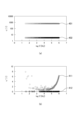
- FIG. 13 is a diagram showing examples of measurement results of an electrode portion using a parallel plate electrode and an interdigital electrode (before improvement).
- FIG. 4 is a diagram for explaining an equivalent circuit of an electrode portion according to an embodiment of the present invention.
- FIG. 4 is a diagram for explaining an equivalent circuit of an electrode portion according to an embodiment of the present invention.
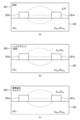
- FIG. 4 is a diagram for explaining an equivalent circuit of an electrode portion according to an embodiment of the present invention.
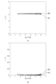
- FIG. 13 is a diagram showing examples of measurement results of an electrode portion using a parallel plate electrode and an interdigital electrode (after improvement).
- FIG. 13 is a diagram showing an example of the measurement results of the electrode portion using the interdigital electrode (improved) according to the present invention.
- the lubricant which is an example of a sample to be measured in the present embodiment, includes lubricating oil and grease, but is not particularly limited thereto.
- FIG. 1 is a conceptual diagram showing the configuration of an electrode unit and an AC power source when evaluating (measuring) the electrical properties of a lubricant.
- FIG. 1(a) shows an outline of the configuration when performing measurements using a parallel plate electrode unit 100 (hereinafter also referred to as "parallel plate electrodes") in a conventional configuration.
- a parallel plate electrode unit 100 hereinafter also referred to as "parallel plate electrodes”
- a lubricant 103 e.g., grease in a bulk state
- the distance between the parallel plate electrodes 101, 102 here may be configured to be, for example, on the order of mm.
- FIG. 1(b) shows a schematic configuration for measurement using the measurement unit 300 according to this embodiment.
- the measurement unit 300 has two interdigital electrodes 301, 302 configured on a substrate 303, to which power is applied by an AC power source 200.
- a more specific configuration example of the interdigital electrodes will be described later, but the two interdigital electrodes 301, 302 are arranged so that the teeth of the electrodes interdigitate with each other.
- FIG. 2 is a schematic diagram showing an enlarged view of the teeth 301a, 302a of the comb-shaped electrodes 301, 302 in the measuring unit 300 according to the present embodiment.
- the comb-shaped electrodes 301, 302 are arranged to mesh with each other, so that the teeth 301a, 302a are arranged alternately.
- the comb-shaped electrodes 301, 302 may be made of, for example, Au (gold), and the substrate 303 may be made of SiO 2 (silicon dioxide).
- Each of the comb-shaped electrodes 301, 302 may have a plurality of teeth, and may be formed with, for example, 66 teeth each, for a total of 132 teeth.
- the dimensions of the teeth may be 0.1 ⁇ m in height and 4.0 mm in length. Furthermore, the teeth 301a of the comb-shaped electrode 301 and the teeth 302a of the comb-shaped electrode 302 are arranged in parallel along the depth direction in FIG. 2, and the interval between them may be 5.0 ⁇ m.
- the above dimensions of the measuring unit 300 are merely an example and are not limiting.
- FIG. 2(b) shows the state in which the lubricant 400 to be measured has been dropped onto the measuring unit 300.
- the amount of lubricant 400 can be less than 10 mg, which is assumed to be approximately 1/1000 of the amount measured by a measuring device using a parallel plate electrode unit 100 as shown in FIG. 1(a).
- Fig. 3(a) is a conceptual diagram that simplifies the diagram of the measuring unit 300 shown in Fig. 2(a) and shows the teeth of the interdigital electrodes 301 and 302 as one each.
- the dashed lines indicate the electric field when an alternating current is applied.
- Fig. 3(b) shows an electrically equivalent circuit based on the configuration shown in Fig. 3(a).
- V
- I
- exp (j ⁇ )
- the complex dielectric constants ( ⁇ r ', ⁇ r ' ') can be derived from the distance and electrode area of the interdigital electrodes 301 and 302 .
- FIG. 4 shows the complex dielectric constants ( ⁇ r ', ⁇ r '') obtained from the measurement results using a measurement apparatus with a conventional configuration using parallel plate electrodes and a measurement apparatus with a comb-shaped electrode.
- the horizontal axis shows the logarithm of the frequency [Hz] by the sweep of the AC power supply
- the vertical axis shows the real part ⁇ r ' of the complex dielectric constant.
- Plot 401 shows the measurement results using the measurement apparatus with the comb-shaped electrodes
- plot 402 shows the measurement results using the measurement apparatus with the parallel plate electrodes.
- the horizontal axis is a semi-logarithmic graph showing the logarithm of the frequency [Hz] by the sweep of the AC power supply
- the vertical axis is a semi-logarithmic graph showing the imaginary part ⁇ r ′′ of the complex dielectric constant.
- Plot 411 shows the measurement results using a measuring device that uses interdigital electrodes
- plot 412 shows the measurement results using a measuring device that uses parallel plate electrodes.
- FIG. 5(a) is a conceptual diagram that simplifies the diagram of the measuring unit 300 shown in FIG. 2(a) and shows the teeth of the interdigital electrodes 301, 302 as one each.
- dashed line 501 indicates the direct electric field between the electrodes when an alternating current is applied (hereinafter also referred to as the "interelectrode electric field”).
- Dashed line 502 indicates the electric field that wraps around the upper part of the electrode (hereinafter also referred to as the "upper side electric field”).
- Dashed line 503 indicates the electric field that wraps around the substrate 303 side (hereinafter also referred to as the "substrate side electric field”).
- FIG. 5(b) shows an improved electrically equivalent circuit based on the configuration shown in FIG. 5(a). Materials with different properties are located in the regions corresponding to each electric field.
- the equivalent circuit shown in Figure 5(b) has the configuration of an electric circuit in which parallel circuits, in which a capacitor C and a resistor R corresponding to each of the three electric fields (regions) mentioned above are connected in parallel, are connected in parallel. An AC current is applied to this equivalent circuit from an AC power source.
- a calculation formula for deriving the complex dielectric constant is defined based on the configuration shown in Fig. 5.
- the dielectric constant ⁇ tol of a standard sample (toluene is used here) and the dielectric constant ⁇ air in a state without a sample (i.e., air) are derived in advance, and based on the results, parameters dependent on the fringing electric field are eliminated from the formula for deriving the dielectric constant ⁇ of the lubricant (sample). This will be explained in more detail below.
- FIG. 6(a) shows the state in which a sample 601 is placed in the measurement unit 300 in the schematic configuration shown in FIG. 5(a). At this time, the dielectric constant ⁇ of the sample 601 is unknown, and the objective is to derive it.
- FIG. 6B corresponds to a state in which a sample 601 is not placed in the measurement unit 300 in the schematic configuration shown in FIG. 5A, that is, a state in which air 602 is present at the measurement position as a background sample (hereinafter also referred to as a "background sample").
- a background sample a background sample
- the dielectric constant ⁇ air of the air 602 is known.
- Fig. 6C shows a state in which a standard sample 603 is placed in the measurement unit 300 in the schematic configuration shown in Fig. 5A. At this time, the dielectric constant ⁇ tol and the electrical conductivity ⁇ tol of the standard sample 603 are known.
- Y * complex admittance of the entire equivalent circuit of the interdigital electrodes
- Ye * complex admittance of the equivalent circuit corresponding to the upper electric field
- Yi * complex admittance of the equivalent circuit corresponding to the interelectrode electric field
- Yb * complex admittance of the equivalent circuit corresponding to the substrate electric field
- the complex admittances Y e * , Y i * , and Y b * can be expressed as the following formulas (5) to (7) using the imaginary unit j.
- S b /d b , S i /d i , and S e /d e are the reciprocals of the equivalent cell constants of the substrate, the space between the electrodes, and the upper part of the electrodes, respectively, and correspond to the electrode area/electrode distance in the case of parallel plate electrodes shown in FIG. 1(a).
- ⁇ SiO2 , Sb / db , and ( Si / di + Se / de ) shown in formula (12) are values that may vary depending on the manufacturing precision of the electrodes, and therefore are eliminated in this embodiment.
- equation (18) based on equations (12) to (14), calculations are performed as in equations (15) to (17) below, and rearranged with respect to ⁇ to obtain equation (18).
- equation (25) based on equations (15) and (20) to (22), calculations are performed as in equations (23) and (24) below, and rearranged in terms of ⁇ / ⁇ to obtain equation (25).
- FIG. 7 shows the complex dielectric constants ( ⁇ r ', ⁇ r ") obtained from the measurement results of a measurement apparatus using parallel plate electrodes of a conventional configuration and a measurement apparatus using interdigital electrodes according to this embodiment.
- the horizontal axis shows the logarithm of the frequency [Hz] by the sweep of the AC power supply
- the vertical axis shows the real part ⁇ r ' of the complex dielectric constant.
- Plot 701 shows the measurement result of the measurement apparatus using interdigital electrodes
- plot 402 shows the measurement result of the measurement apparatus using parallel plate electrodes, similar to FIG. 4(a).
- the horizontal axis indicates the logarithm of the frequency [Hz] by the sweep of the AC power supply
- the vertical axis indicates the imaginary part ⁇ r ′′ of the complex dielectric constant, which is a semi-log graph.
- Plot 702 indicates the measurement result of the measurement device using the interdigital electrode according to this embodiment
- plot 412 indicates the measurement result of the measurement device using parallel plate electrodes, similar to FIG. 4( b ).
- the measurement results obtained by the measurement device using parallel plate electrodes and the measurement device using interdigital electrodes are almost the same.
- the measurement device using interdigital electrodes according to this embodiment can achieve the same level of accuracy as the measurement device using parallel plate electrodes.
- FIG. 8 shows the complex dielectric constants ⁇ r ' and ⁇ r " obtained from the measurement results of a new lubricant and a deteriorated lubricant using the measurement device using the interdigital electrodes according to this embodiment.
- the horizontal axis is a semi-logarithmic graph showing the logarithm of the frequency [Hz] obtained by the sweep of the AC power supply
- the vertical axis is a semi-logarithmic graph showing the real part ⁇ r ' of the complex dielectric constant.
- plot 701 shows the measurement results (new lubricant) using the measurement device using the interdigital electrodes
- plot 801 shows the measurement results (deteriorated lubricant) using the measurement device using the interdigital electrodes.
- FIG. 8( b ) is a semi-log graph in which the horizontal axis indicates the logarithm of the frequency [Hz] by the sweep of the AC power supply, and the vertical axis indicates the imaginary part ⁇ r ′′ of the complex dielectric constant. Similar to FIG. 7( b ), plot 702 indicates the measurement result (new lubricant) of the measurement device using the interdigital electrode according to this embodiment, and plot 802 indicates the measurement result (deteriorated lubricant) of the measurement device using the interdigital electrode.
- the method according to this embodiment makes it possible to identify the deterioration state of a lubricant using a measuring device that uses interdigital electrodes.
- the measurement device using the interdigital electrodes can obtain measurement results equivalent to those of a measurement device using parallel plate electrodes.
- the interdigital electrodes can perform measurements using an extremely small amount of sample (e.g., lubricant) compared to parallel plate electrodes, making them more useful than parallel plate electrodes.
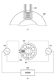
- FIG. 9 is a schematic diagram for explaining an application example of the measurement method using the interdigital electrodes according to this embodiment.
- a rolling bearing lubricated with a lubricant is used as a measurement target.
- a seal 900 is used that can be attached to a position in the rolling bearing where the lubricant can be contacted.
- the interdigital electrodes 301 and 302 of the measurement unit 300 having the interdigital electrodes as shown in FIG. 1(b) are printed on the seal 900.
- a voltage is applied to the interdigital electrodes to measure impedance.
- the detection results are input into the calculation formulas shown in the above formulas (19) and (26), and the parameters of the rolling bearing can be obtained. Note that the parameters of the background measurement and the standard sample measurement may be measured in advance.
- FIG. 9(b) is an example diagram showing an overall schematic of a measurement system including a measurement device 920 and a measurement unit 300.
- a seal 900 on which the measurement unit 300 is printed may be installed, with the lubricant 902 in a rolling bearing 901 as the measurement target.
- the measurement device 920 may be configured to perform measurements using EIS (electrochemical impedance spectroscopy) using an AC power source 200, and EIM (electrical impedance spectroscopy) using an AC power source 910. This makes it possible to improve the accuracy of EIM by correcting the measurement results by EIM based on the highly accurate measurement results by the interdigital electrodes according to this embodiment.
- EIS electrochemical impedance spectroscopy
- EIM electrical impedance spectroscopy
- the measuring device 920 may be realized, for example, by an information processing device including a control device, a storage device, and an output device (not shown).
- the control device may be composed of a CPU (Central Processing Unit), an MPU (Micro Processing Unit), a DSP (Digital Single Processor), or a dedicated circuit.
- the storage device is composed of volatile and non-volatile storage media such as a HDD (Hard Disk Drive), a ROM (Read Only Memory), or a RAM (Random Access Memory), and can input and output various information in response to instructions from the control device.
- the output device is composed of a speaker, a light, or a display device such as a liquid crystal display, and notifies the operator in response to instructions from the control device.
- the output method by the output device is not particularly limited.
- the output device may also be a network interface equipped with a communication function, and may perform output operations by transmitting data to an external device (not shown) via a network (not shown).
- the measuring device 920 specifies the input value of the power to be applied to the measuring unit 300 equipped with an interdigital electrode, which is the AC voltage V of the angular frequency ⁇ of the AC power source 200, and obtains the impedance Z and phase angle ⁇ as the corresponding output (measured value). The measuring device 920 then uses these values to derive parameters that indicate the electrical characteristics of the object to be measured, and outputs them.
- [Processing flow] 10 is a flowchart of the measurement process according to the present embodiment using the above method.
- This process is executed by the measurement device 920, and may be realized, for example, by a control device (not shown) included in the measurement device 920 reading out a program for implementing the process according to the present embodiment from a storage device (not shown) and executing it.
- the derivation of parameters in the following process may be configured to be partially implemented using the functions of general-purpose software.
- the comb-shaped electrode of the measurement unit 300 is placed at the measurement position, and is in a state such as that shown in FIG. 2(b), for example.
- the measuring device 920 controls the LCR meter (not shown) to apply power of an AC voltage V with an angular frequency ⁇ to the measurement object via the comb-shaped electrodes of the measuring unit 300 using the AC power source 200 provided in the LCR meter.
- an AC voltage V with an angular frequency ⁇ is applied to the sample (e.g., the lubricant in a rolling bearing).
- the measuring device 920 acquires the impedance Z and phase angle ⁇ from the LCR meter as the output for the input instructed in S1001.
- the LCR meter outputs the impedance Z and phase angle ⁇ to the measuring device 920 as the measurement results of the sample for the input AC voltage V of angular frequency ⁇ .
- the measuring device 920 acquires the measurement results of a previously performed background measurement (FIG. 6(b)) and various parameters of the background (air in the above example). It is assumed that this information has been input in advance by measurement or the like and registered so that it can be used by the measuring device 920.
- the various parameters related to the background may be configured to be specified by the user of the measuring device 920.
- the measuring device 920 acquires the measurement results of a previously performed standard sample measurement (FIG. 6(c)) and various parameters of the standard sample (toluene in the above example). It is assumed that this information has been input in advance by measurement or the like and registered so that it can be used by the measuring device 920.
- the various parameters related to the standard sample may be configured to be specified by the user of the measuring device 920.
- the measuring device 920 derives the complex dielectric constant of the sample by introducing the measurement results for the sample obtained in S1002 and the various parameters acquired in S1003 and S1004 into the above formula (19) and formula (26). Furthermore, the measuring device 920 derives the dielectric constant ⁇ and conductivity ⁇ for the sample using the above calculation formula based on the derived complex dielectric constant.
- the measurement device 920 outputs the value obtained in S1005 as the measurement result. Then, this processing flow ends.
- this embodiment makes it possible to measure the state of a minute amount of sample with high accuracy.
- the configuration having the measuring section of the interdigital electrode according to the present invention is not limited to lubricants, but may be used to measure various samples. For example, it may be used to detect the degree of deterioration of the sample as described above, or the inclusion of multiple substances. Furthermore, the measurement is not limited to mechanical devices, and may be performed on samples such as liquids collected from living organisms such as humans.
- the electrodes are comb-shaped, that is, arranged opposite each other so that the teeth of the comb-shaped electrodes interlock, but this is not limited to this.
- a spiral-shaped electrode may also be used.
- an example was shown in which an AC voltage was used as the applied voltage.
- this is not limited to this, and a pulse input or a predetermined rectangular voltage may also be used. Therefore, as long as the measurement results can be compared with those of background measurements and standard sample measurements, the configuration of the applied voltage is not particularly limited.
- the present invention can also be realized by supplying a program or application for realizing the functions of one or more of the above-mentioned embodiments to a system or device via a network or storage medium, etc., and having one or more processors in the computer of the system or device read and execute the program.
- ASIC Application Specific Integrated Circuit
- FPGA Field Programmable Gate Array
- the present invention is not limited to the above-described embodiment, and the invention also contemplates the mutual combination of the various components of the embodiment, as well as modifications and applications by those skilled in the art based on the descriptions in the specification and well-known technology, and these are included in the scope of the protection sought.
- a measurement step (e.g., S1001, S1002) of measuring impedance by applying a predetermined voltage to a measurement target (e.g., 400) via a measurement unit (e.g., 300) including electrodes (e.g., 301, 302) of a predetermined shape and a substrate (e.g., 303) on which the electrodes are formed;
- a derivation step (e.g., S1003, S1004, S1005) of deriving a complex dielectric constant of the object to be measured by inputting a measurement result from the measurement step into a predetermined calculation formula defined based on an equivalent circuit (e.g., FIG.
- the equivalent circuit is defined in correspondence with an electric field between the electrodes in the measurement unit (e.g., 501), an electric field on the substrate side of the electrodes (e.g., 503), and an electric field on the measurement target side of the electrodes (e.g., 502);
- the measurement method characterized in that the predetermined calculation formula is defined to include parameters based on the measurement results of a standard sample (e.g., 603) and the measurement results of a background sample (e.g., 602) by the measurement unit.
- This configuration makes it possible to measure the state of a minute amount of sample with high accuracy, and in particular to achieve measurement accuracy equivalent to that of parallel plate electrodes, but with a much smaller amount.
- the predetermined shape is a comb shape
- the measurement method according to (1) wherein two comb-shaped electrodes are arranged on the surface of the substrate so as to face each other and have interdigitated teeth.
- the comb shape increases the contact area of the electrode with the sample, enabling highly accurate measurement.
- the measuring unit is installed on a rolling bearing (e.g., 901), The measurement method according to (1), wherein the measurement object is a lubricant (e.g., 902) in the rolling bearing.
- a rolling bearing e.g., 901
- the measurement object is a lubricant (e.g., 902) in the rolling bearing.
- a measuring unit including an electrode (e.g., 301, 302) having a predetermined shape and a substrate (e.g., 303) on which the electrode is formed;
- a power supply unit e.g., 200
- a measuring means e.g., 920
- a derivation means e.g., 920
- the equivalent circuit is defined in correspondence with an electric field between the electrodes in the measurement unit (e.g., 501), an electric field on the substrate side of the electrodes (e.g., 503), and an electric field on the measurement target side of the electrodes (e.g., 502);
- a measurement system characterized in that the predetermined calculation formula is defined to include parameters based on the measurement results of a standard sample (e.g., 603) and the measurement results of a background sample (e.g., 602) by the measurement unit.
- a measurement step (e.g., S1001, S1002) of measuring impedance by applying a predetermined voltage to a measurement target (e.g., 400) via a measurement unit (e.g., 300) including electrodes (e.g., 301, 302) of a predetermined shape and a substrate (e.g., 303) on which the electrodes are formed; a derivation step (e.g., S1003, S1004, S1005) of deriving a complex dielectric constant of the object to be measured by inputting a measurement result from the measurement step into a predetermined calculation formula defined based on an equivalent circuit (e.g., FIG.
- the equivalent circuit is defined in correspondence with an electric field between the electrodes in the measurement unit (e.g., 501), an electric field on the substrate side of the electrodes (e.g., 503), and an electric field on the measurement target side of the electrodes (e.g., 502);
- the predetermined calculation formula is defined including parameters based on the measurement results of a standard sample (e.g., 603) and the measurement results of a background sample (e.g., 602) by the measurement unit.
Landscapes
- Chemical & Material Sciences (AREA)
- Physics & Mathematics (AREA)
- General Physics & Mathematics (AREA)
- Life Sciences & Earth Sciences (AREA)
- Electrochemistry (AREA)
- Health & Medical Sciences (AREA)
- Chemical Kinetics & Catalysis (AREA)
- Analytical Chemistry (AREA)
- Biochemistry (AREA)
- General Health & Medical Sciences (AREA)
- Immunology (AREA)
- Pathology (AREA)
- Measurement Of Resistance Or Impedance (AREA)
- Investigating Or Analyzing Materials By The Use Of Electric Means (AREA)
Abstract
Description
所定の形状の電極と当該電極が表面に形成される基板とを含む測定部を介して、測定対象に所定の電圧を印加させることによりインピーダンスを測定する測定工程と、
前記測定工程による測定結果を、前記測定部と前記測定対象の構成に対応する等価回路に基づいて規定される所定の算出式に入力することにより、前記測定対象の複素誘電率を導出する導出工程と、
を有し、
前記等価回路は、前記測定部における前記電極間の電場と、前記電極の基板側の電場と、前記電極の前記測定対象側の電場とに対応して規定され、
前記所定の算出式は、前記測定部による標準試料の測定結果およびバックグラウンド試料の測定結果に基づくパラメータを含んで規定される。
所定の形状の電極と当該電極が表面に形成される基板とを含む測定部と、
所定の電圧を供給する電源部と、
前記測定部を介して、測定対象に前記電源部からの所定の電圧を印加させることによりインピーダンスを測定する測定手段と、
前記測定手段による測定結果を、前記測定部と前記測定対象の構成に対応する等価回路に基づいて規定される所定の算出式に入力することにより、前記測定対象の複素誘電率を導出する導出手段と、
を有し、
前記等価回路は、前記測定部における前記電極間の電場と、前記電極の基板側の電場と、前記電極の前記測定対象側の電場とに対応して規定され、
前記所定の算出式は、前記測定部による標準試料の測定結果およびバックグラウンド試料の測定結果に基づくパラメータを含んで規定される。
コンピュータに、
所定の形状の電極と当該電極が表面に形成される基板とを含む測定部を介して、測定対象に所定の電圧を印加させることによりインピーダンスを測定する測定工程と、
前記測定工程による測定結果を、前記測定部と前記測定対象の構成に対応する等価回路に基づいて規定される所定の算出式に入力することにより、前記測定対象の複素誘電率を導出する導出工程と、
を実行させ、
前記等価回路は、前記測定部における前記電極間の電場と、前記電極の基板側の電場と、前記電極の前記測定対象側の電場とに対応して規定され、
前記所定の算出式は、前記測定部による標準試料の測定結果およびバックグラウンド試料の測定結果に基づくパラメータを含んで規定される。
以下、本発明の第1の実施形態について説明を行う。
まず、本実施形態に係る潤滑剤による潤滑状態の測定に用いられる電極構成について説明する。本実施形態において測定対象となる試料の一例である潤滑剤としては、潤滑油やグリースなどが含まれるが、特に限定するものではない。
V=|V|exp(jωt) …(1)
I=|I|exp(j(ωt-θ)) …(2)
Z=V/I=|V/I|exp(jθ)=|Z|exp(jθ) …(3)
j:虚数
ω:電圧の角周波数
t:時間
θ:位相角(電圧と電流の位相のずれ)
次に、図3に示した等価回路を前提として、本願発明者は、従来の構成である平行平板電極を用いた測定装置と、くし型電極を用いた測定装置について事前検証を行っており、その検証結果について示す。なお、例えば、特許文献1に示す平行平板電極を用いた測定装置は、高い測定精度を実現できる。
以下、本実施形態に係るくし型電極を用いた測定装置による複素誘電率の導出について説明する。図3(a)の例では、くし型電極の歯の間に直接的な電場のみを想定していた。これに対し、本実施形態に係るくし型電極を用いた測定装置では、電極を回り込む電場を更に考慮する。つまり、くし型電極の電極面積(金蒸着膜の厚さ)に対し、電極間距離が長いことに着目し、その電場の回り込みを考慮する。

Ye *:上部側電場に対応する等価回路の複素アドミッタンス
Yi *:電極間電場に対応する等価回路の複素アドミッタンス
Yb *:基板側電場に対応する等価回路の複素アドミッタンス
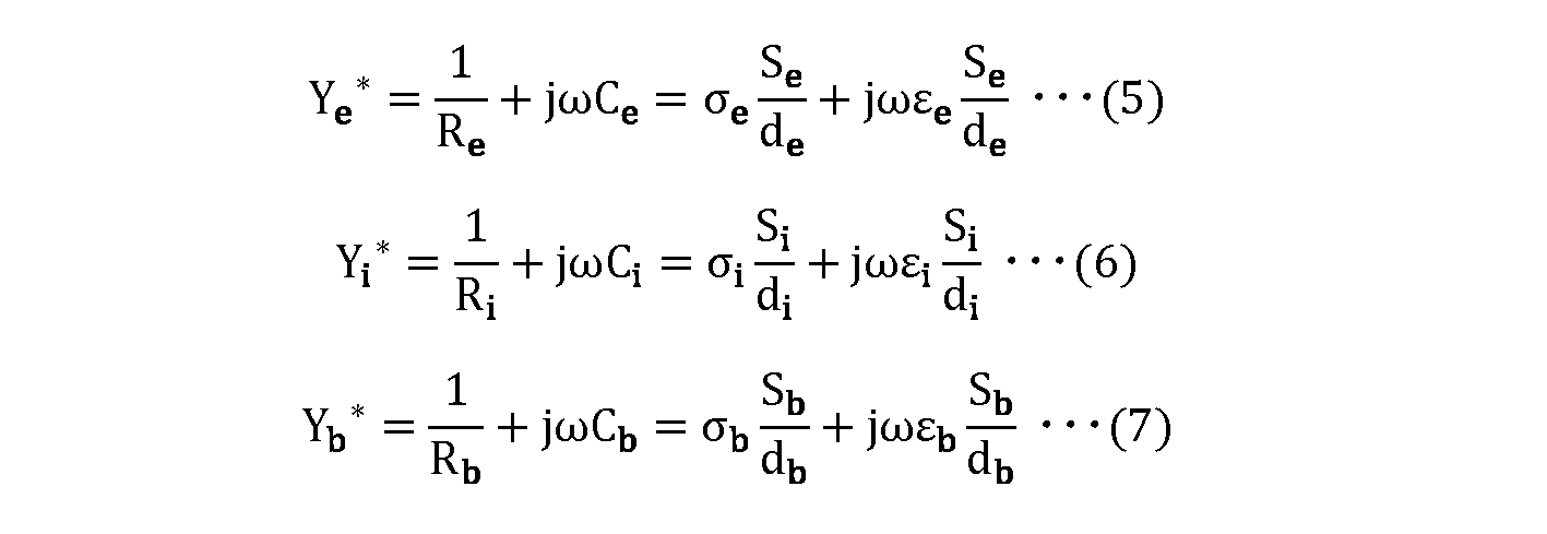
ω:電圧の角周波数
Re:電極上部に存在する物質の抵抗
Ri:電極間に存在する物質の抵抗
Rb:基板の抵抗
Ce:電極上部に存在する物質のキャパシタンス
Ci:電極間に存在する物質のキャパシタンス
Cb:基板のキャパシタンス
Se:上部側電場に対応する電極面積
Si:電極間電場に対応する電極面積
Sb:基板側電場に対応する電極面積
de:上部側電場に対応する電極間の距離
di:電極間電場に対応する電極間の距離
db:基板側電場に対応する電極間の距離
σe:電極上部に存在する導電率
σi:電極間に存在する物質の導電率
σb:基板の導電率
εe:電極上部に存在する物質の誘電率
εi:電極間に存在する物質の誘電率
εb:基板の誘電率




εSiO2:基板(SiO2)の誘電率

εair:バックグラウンド試料(空気)の誘電率

εtol:標準試料(トルエン)の誘電率




σSiO2:基板(SiO2)の導電率

σair:バックグラウンド(空気)の導電率
σb=σSiO2の関係と、上記の(10)により、以下の式(22)にて表される。

σtol:標準試料(トルエン)の導電率
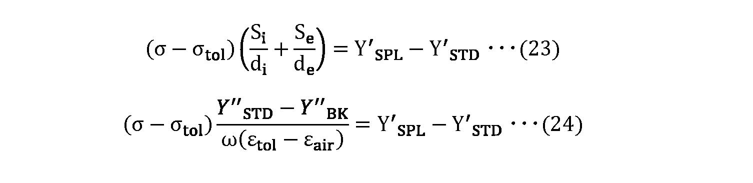



図7、および図8は、本実施形態に係る測定結果の例を示す図である。
図9は、本実施形態に係るくし型電極を用いた測定方法の適用例を説明するための概略図である。例えば、測定対象として、潤滑剤にて潤滑が行われる転がり軸受が挙げられる。そして、転がり軸受内の潤滑剤に接触可能な位置に貼り付け可能なシール900を用いる。図9(a)に示すように、シール900上には、図1(b)に示すようなくし型電極を備える測定部300のくし型電極301、302を印刷する。シール900を転がり軸受に張り付けた状態で、くし型電極に電圧を印加することでインピーダンスを測定する。その検出結果を、上記の式(19)や式(26)に示した算出式に入力することで、転がり軸受のパラメータを得ることが可能となる。なお、バックグラウンド測定や標準試料測定のパラメータは予め測定されていてよい。
図10は、上記の手法を用いた、本実施形態に係る測定処理のフローチャートである。本処理は、測定装置920により実行され、例えば、測定装置920が備える制御装置(不図示)が本実施形態に係る処理を実現するためのプログラムを記憶装置(不図示)から読み出して実行することにより実現されてよい。なお、以下の処理におけるパラメータの導出は、汎用のソフトウェアの機能を用いてその一部が実現されるように構成されてよい。また、本処理フローが開始される際には、測定部300のくし型電極が測定位置に設置され、例えば、図2(b)に示すような状態になっているものとする。
また、本発明に係るくし型電極の測定部を有する構成は、潤滑剤に限定するものではなく、様々な試料の測定に用いられてもよい。例えば、上述したような試料の劣化の程度、多物質の混入の検出に用いられてもよい。また、機械装置のみを対象とするものではなく、例えば、人などの生物などから採取された液体などの試料を対象として測定が行われてもよい。
(1) 所定の形状の電極(例えば、301、302)と当該電極が表面に形成される基板(例えば、303)とを含む測定部(例えば、300)を介して、測定対象(例えば、400)に所定の電圧を印加させることによりインピーダンスを測定する測定工程(例えば、S1001、S1002)と、
前記測定工程による測定結果を、前記測定部と前記測定対象の構成に対応する等価回路(例えば、図5(b))に基づいて規定される所定の算出式に入力することにより、前記測定対象の複素誘電率を導出する導出工程(例えば、S1003、S1004、S1005)と、
を有し、
前記等価回路は、前記測定部における前記電極間の電場(例えば、501)と、前記電極の基板側の電場(例えば、503)と、前記電極の前記測定対象側の電場(例えば、502)とに対応して規定され、
前記所定の算出式は、前記測定部による標準試料(例えば、603)の測定結果およびバックグラウンド試料(例えば、602)の測定結果に基づくパラメータを含んで規定される、ことを特徴とする測定方法。
この構成によれば、微量な試料の状態を高精度に測定することが可能となる。特に、平行平板電極と同等の測定精度を、より微小な量にて実現することが可能となる。

ε”:複素誘電率ε*の虚部成分
Y’STD:標準試料の複素アドミッタンスの実部
Y”STD:標準試料の複素アドミッタンスの虚部
Y”BK:バックグラウンドの複素アドミッタンスの虚部
Y’SPL:試料の複素アドミッタンスの実部
Y”SPL:試料の複素アドミッタンスの虚部
ω:電圧の角周波数
σtol:標準試料の導電率
εair:バックグラウンド試料の誘電率
εtol:標準試料の誘電率
にて規定される、(1)に記載の測定方法。
この構成によれば、電場解析を不要としつつ、電極間および電極への回り込みの電場を考慮した測定が可能となる。
前記基板の表面において、2つのくし型形状の電極が対向して、くしの歯が噛み合うように配置される、(1)に記載の測定方法。
この構成によれば、くし形形状により電極における試料との接触面積を広げ、精度の高い測定が可能となる。
前記測定対象は、前記転がり軸受内の潤滑剤(例えば、902)である、(1)に記載の測定方法。
この構成によれば、転がり軸受内の潤滑剤を測定対象として、微量の試料にて精度の高い測定が可能となる。
所定の電圧を供給する電源部(例えば、200)と、
前記測定部を介して、測定対象に前記電源部からの所定の電圧を印加させることによりインピーダンスを測定する測定手段(例えば、920)と、
前記測定手段による測定結果を、前記測定部と前記測定対象の構成に対応する等価回路(例えば、図5(b))に基づいて規定される所定の算出式に入力することにより、前記測定対象の複素誘電率を導出する導出手段(例えば、920)と、
を有し、
前記等価回路は、前記測定部における前記電極間の電場(例えば、501)と、前記電極の基板側の電場(例えば、503)と、前記電極の前記測定対象側の電場(例えば、502)とに対応して規定され、
前記所定の算出式は、前記測定部による標準試料(例えば、603)の測定結果およびバックグラウンド試料(例えば、602)の測定結果に基づくパラメータを含んで規定される、ことを特徴とする測定システム。
この構成によれば、微量な試料の状態を高精度に測定することが可能となる。特に、平行平板電極と同等の測定精度を、より微小な量にて実現することが可能となる。
所定の形状の電極(例えば、301、302)と当該電極が表面に形成される基板(例えば、303)とを含む測定部(例えば、300)を介して、測定対象(例えば、400)に所定の電圧を印加させることによりインピーダンスを測定する測定工程(例えば、S1001、S1002)と、
前記測定工程による測定結果を、前記測定部と前記測定対象の構成に対応する等価回路(例えば、図5(b))に基づいて規定される所定の算出式に入力することにより、前記測定対象の複素誘電率を導出する導出工程(例えば、S1003、S1004、S1005)と、
を実行させ、
前記等価回路は、前記測定部における前記電極間の電場(例えば、501)と、前記電極の基板側の電場(例えば、503)と、前記電極の前記測定対象側の電場(例えば、502)とに対応して規定され、
前記所定の算出式は、前記測定部による標準試料(例えば、603)の測定結果およびバックグラウンド試料(例えば、602)の測定結果に基づくパラメータを含んで規定される、プログラム。
この構成によれば、微量な試料の状態を高精度に測定することが可能となる。特に、平行平板電極と同等の測定精度を、より微小な量にて実現することが可能となる。
300 測定部
301、302 くし型電極
303 基板
900 シール
901 転がり軸受
902 潤滑剤
920 測定装置
Claims (6)
- 所定の形状の電極と当該電極が表面に形成される基板とを含む測定部を介して、測定対象に所定の電圧を印加させることによりインピーダンスを測定する測定工程と、
前記測定工程による測定結果を、前記測定部と前記測定対象の構成に対応する等価回路に基づいて規定される所定の算出式に入力することにより、前記測定対象の複素誘電率を導出する導出工程と、
を有し、
前記等価回路は、前記測定部における前記電極間の電場と、前記電極の基板側の電場と、前記電極の前記測定対象側の電場とに対応して規定され、
前記所定の算出式は、前記測定部による標準試料の測定結果およびバックグラウンド試料の測定結果に基づくパラメータを含んで規定される、ことを特徴とする測定方法。 - 前記所定の算出式は、

ε’:複素誘電率ε*の実部成分
ε”:複素誘電率ε*の虚部成分
Y’STD:標準試料の複素アドミッタンスの実部
Y”STD:標準試料の複素アドミッタンスの虚部
Y”BK:バックグラウンドの複素アドミッタンスの虚部
Y’SPL:試料の複素アドミッタンスの実部
Y”SPL:試料の複素アドミッタンスの虚部
ω:電圧の角周波数
σtol:標準試料の導電率
εair:バックグラウンド試料の誘電率
εtol:標準試料の誘電率
にて規定される、ことを特徴とする請求項1に記載の測定方法。 - 前記所定の形状は、くし型形状であり、
前記基板の表面において、2つのくし型形状の電極が対向して、くしの歯が噛み合うように配置される、ことを特徴とする請求項1に記載の測定方法。 - 前記測定部は、転がり軸受に設置され、
前記測定対象は、前記転がり軸受内の潤滑剤である、ことを特徴とする請求項1に記載の測定方法。 - 所定の形状の電極と当該電極が表面に形成される基板とを含む測定部と、
所定の電圧を供給する電源部と、
前記測定部を介して、測定対象に前記電源部からの所定の電圧を印加させることによりインピーダンスを測定する測定手段と、
前記測定手段による測定結果を、前記測定部と前記測定対象の構成に対応する等価回路に基づいて規定される所定の算出式に入力することにより、前記測定対象の複素誘電率を導出する導出手段と、
を有し、
前記等価回路は、前記測定部における前記電極間の電場と、前記電極の基板側の電場と、前記電極の前記測定対象側の電場とに対応して規定され、
前記所定の算出式は、前記測定部による標準試料の測定結果およびバックグラウンド試料の測定結果に基づくパラメータを含んで規定される、ことを特徴とする測定装置。 - コンピュータに、
所定の形状の電極と当該電極が表面に形成される基板とを含む測定部を介して、測定対象に所定の電圧を印加させることによりインピーダンスを測定する測定工程と、
前記測定工程による測定結果を、前記測定部と前記測定対象の構成に対応する等価回路に基づいて規定される所定の算出式に入力することにより、前記測定対象の複素誘電率を導出する導出工程と、
を実行させ、
前記等価回路は、前記測定部における前記電極間の電場と、前記電極の基板側の電場と、前記電極の前記測定対象側の電場とに対応して規定され、
前記所定の算出式は、前記測定部による標準試料の測定結果およびバックグラウンド試料の測定結果に基づくパラメータを含んで規定される、プログラム。
Priority Applications (2)
| Application Number | Priority Date | Filing Date | Title |
|---|---|---|---|
| CN202380077617.0A CN120188034A (zh) | 2022-11-07 | 2023-11-06 | 测定方法、测定系统以及程序 |
| JP2024557402A JPWO2024101320A1 (ja) | 2022-11-07 | 2023-11-06 |
Applications Claiming Priority (2)
| Application Number | Priority Date | Filing Date | Title |
|---|---|---|---|
| JP2022-178451 | 2022-11-07 | ||
| JP2022178451 | 2022-11-07 |
Publications (1)
| Publication Number | Publication Date |
|---|---|
| WO2024101320A1 true WO2024101320A1 (ja) | 2024-05-16 |
Family
ID=91032501
Family Applications (1)
| Application Number | Title | Priority Date | Filing Date |
|---|---|---|---|
| PCT/JP2023/039926 Ceased WO2024101320A1 (ja) | 2022-11-07 | 2023-11-06 | 測定方法、測定システム、およびプログラム |
Country Status (4)
| Country | Link |
|---|---|
| JP (1) | JPWO2024101320A1 (ja) |
| CN (1) | CN120188034A (ja) |
| TW (1) | TW202426913A (ja) |
| WO (1) | WO2024101320A1 (ja) |
Citations (4)
| Publication number | Priority date | Publication date | Assignee | Title |
|---|---|---|---|---|
| US20050227373A1 (en) * | 2002-06-24 | 2005-10-13 | Denis Flandre | Method and device for high sensitivity detection of the presence of dna and other probes |
| JP2012184948A (ja) * | 2011-03-03 | 2012-09-27 | Takenaka Komuten Co Ltd | コンクリート体の塩分濃度測定システム及びコンクリート体の塩分濃度測定方法 |
| JP2019028012A (ja) * | 2017-08-03 | 2019-02-21 | 東北電子産業株式会社 | 複素誘電率測定用回路、複素誘電率測定装置及び複素誘電率の測定方法 |
| US20190302078A1 (en) * | 2018-03-27 | 2019-10-03 | National Technology & Engineering Solutions Of Sandia, Llc | Sensor for the Direct Detection of Iodine |
-
2023
- 2023-11-06 JP JP2024557402A patent/JPWO2024101320A1/ja active Pending
- 2023-11-06 WO PCT/JP2023/039926 patent/WO2024101320A1/ja not_active Ceased
- 2023-11-06 CN CN202380077617.0A patent/CN120188034A/zh active Pending
- 2023-11-07 TW TW112142829A patent/TW202426913A/zh unknown
Patent Citations (4)
| Publication number | Priority date | Publication date | Assignee | Title |
|---|---|---|---|---|
| US20050227373A1 (en) * | 2002-06-24 | 2005-10-13 | Denis Flandre | Method and device for high sensitivity detection of the presence of dna and other probes |
| JP2012184948A (ja) * | 2011-03-03 | 2012-09-27 | Takenaka Komuten Co Ltd | コンクリート体の塩分濃度測定システム及びコンクリート体の塩分濃度測定方法 |
| JP2019028012A (ja) * | 2017-08-03 | 2019-02-21 | 東北電子産業株式会社 | 複素誘電率測定用回路、複素誘電率測定装置及び複素誘電率の測定方法 |
| US20190302078A1 (en) * | 2018-03-27 | 2019-10-03 | National Technology & Engineering Solutions Of Sandia, Llc | Sensor for the Direct Detection of Iodine |
Non-Patent Citations (1)
| Title |
|---|
| LEE HUAN L: "The Handbook of Dielectric Analysis and Cure Monitoring", LAMBIENT TECHNOLOGIES, 1 January 2017 (2017-01-01), XP093170040, Retrieved from the Internet <URL:https://static1.squarespace.com/static/59627b143e00be4fb1e3aed9/t/59b9c58f18b27db13da22af4/1505346973511/DielectricAnalysisCureMonitoringHandbook.pdf> * |
Also Published As
| Publication number | Publication date |
|---|---|
| CN120188034A (zh) | 2025-06-20 |
| TW202426913A (zh) | 2024-07-01 |
| JPWO2024101320A1 (ja) | 2024-05-16 |
Similar Documents
| Publication | Publication Date | Title |
|---|---|---|
| CN102667461B (zh) | 润滑油的劣化、变质度测定方法及其测定装置 | |
| TWI490490B (zh) | A method for measuring deterioration of lubricating oil and a measuring device thereof, and a lubricating oil monitoring system for a machine and a device | |
| Tolouei et al. | Development of circuit models for electrochemical impedance spectroscopy (EIS) responses of interdigitated MEMS biochemical sensors | |
| Gilbert et al. | Analysis of electrochemical impedance spectra using phase angle symmetry across log frequency | |
| Arshak et al. | Investigation of tin oxides as sensing layers in conductimetric interdigitated pH sensors | |
| RU2589526C2 (ru) | Система и способ определения толщины исследуемого слоя в многослойной структуре | |
| Chen et al. | Influence of wax precipitation on the impedance spectroscopy of waxy oils | |
| JP7071723B2 (ja) | 複素誘電率測定用回路、複素誘電率測定装置及び複素誘電率の測定方法 | |
| Oommen et al. | Enhanced performance of spiral co-planar inter-digital capacitive structures for sensing applications | |
| US7253644B2 (en) | Apparatus and method for measuring electrochemical and viscoelastic properties of a liquid | |
| Sidambarompoulé et al. | Study of electrical properties and estimation of average mobility and diffusion coefficients in several insulating liquids by dielectric spectroscopy | |
| WO2017075201A1 (en) | Dielectrostrictive sensors for shear stress measurement, process monitoring, and quality examination of viscoelastic materials | |
| JP2022180381A (ja) | 状態診断方法、状態診断装置、およびプログラム | |
| TW202426913A (zh) | 測定方法、測定系統及程式 | |
| Rustomji et al. | Thin-film electrochemical sensor electrode for rapid evaluation of electrolytic conductivity, cyclic voltammetry, and temperature measurements | |
| Sharma et al. | Fundamental characterization techniques: impedance and modulus spectroscopy | |
| JP5946782B2 (ja) | pHセンサ及び該センサを用いた油劣化度検知方法 | |
| TW202426784A (zh) | 膜狀態測定方法、膜狀態測定裝置及程式 | |
| RU2303787C1 (ru) | Способ измерения диэлектрической проницаемости жидких и плоских твердых диэлектриков | |
| RU2063023C1 (ru) | Устройство для измерения удельной электропроводности жидких сред | |
| JP2024140594A (ja) | 潤滑剤の温度および圧力の測定方法、測定装置、およびプログラム | |
| RU2234075C2 (ru) | Бесконтактный способ определения диэлектрической проницаемости твердых и жидких диэлектриков | |
| Shull et al. | Aging characterization of polymeric insulation in aircraft wiring via impedance spectroscopy | |
| JP4866998B2 (ja) | 電子装置の測定装置 | |
| Peev | Impedance approaches to motor oils |
Legal Events
| Date | Code | Title | Description |
|---|---|---|---|
| 121 | Ep: the epo has been informed by wipo that ep was designated in this application |
Ref document number: 23888667 Country of ref document: EP Kind code of ref document: A1 |
|
| WWE | Wipo information: entry into national phase |
Ref document number: 2024557402 Country of ref document: JP |
|
| WWE | Wipo information: entry into national phase |
Ref document number: CN2023800776170 Country of ref document: CN Ref document number: 202380077617.0 Country of ref document: CN |
|
| NENP | Non-entry into the national phase |
Ref country code: DE |
|
| WWP | Wipo information: published in national office |
Ref document number: 202380077617.0 Country of ref document: CN |
|
| 122 | Ep: pct application non-entry in european phase |
Ref document number: 23888667 Country of ref document: EP Kind code of ref document: A1 |