WO2024101092A1 - 衣服 - Google Patents
衣服 Download PDFInfo
- Publication number
- WO2024101092A1 WO2024101092A1 PCT/JP2023/037591 JP2023037591W WO2024101092A1 WO 2024101092 A1 WO2024101092 A1 WO 2024101092A1 JP 2023037591 W JP2023037591 W JP 2023037591W WO 2024101092 A1 WO2024101092 A1 WO 2024101092A1
- Authority
- WO
- WIPO (PCT)
- Prior art keywords
- garment
- adhesive
- nonwoven fabric
- cut parts
- joint
- Prior art date
- Legal status (The legal status is an assumption and is not a legal conclusion. Google has not performed a legal analysis and makes no representation as to the accuracy of the status listed.)
- Ceased
Links
Images



Classifications
-
- A—HUMAN NECESSITIES
- A41—WEARING APPAREL
- A41D—OUTERWEAR; PROTECTIVE GARMENTS; ACCESSORIES
- A41D13/00—Professional, industrial or sporting protective garments, e.g. surgeons' gowns or garments protecting against blows or punches
-
- A—HUMAN NECESSITIES
- A41—WEARING APPAREL
- A41D—OUTERWEAR; PROTECTIVE GARMENTS; ACCESSORIES
- A41D27/00—Details of garments or of their making
-
- A—HUMAN NECESSITIES
- A41—WEARING APPAREL
- A41D—OUTERWEAR; PROTECTIVE GARMENTS; ACCESSORIES
- A41D27/00—Details of garments or of their making
- A41D27/12—Shields or protectors
-
- A—HUMAN NECESSITIES
- A41—WEARING APPAREL
- A41H—APPLIANCES OR METHODS FOR MAKING CLOTHES, e.g. FOR DRESS-MAKING OR FOR TAILORING, NOT OTHERWISE PROVIDED FOR
- A41H43/00—Other methods, machines or appliances
-
- A—HUMAN NECESSITIES
- A41—WEARING APPAREL
- A41H—APPLIANCES OR METHODS FOR MAKING CLOTHES, e.g. FOR DRESS-MAKING OR FOR TAILORING, NOT OTHERWISE PROVIDED FOR
- A41H43/00—Other methods, machines or appliances
- A41H43/04—Joining garment parts or blanks by gluing or welding ; Gluing presses
Definitions
- the present invention relates to clothing. More specifically, the present invention relates to clothing that can shorten processing time, has excellent water pressure resistance, and is comfortable against the skin.
- the clothing described in Patent Document 1 leaves room for improvement in terms of water pressure resistance.
- the clothing described in Patent Document 1 does not have sufficient water pressure resistance, and water easily penetrates inside.
- clothing reinforced with seam tape has poor feel against the skin.
- the present invention was made in consideration of these conventional problems, and aims to provide clothing that can shorten processing time, has excellent water pressure resistance, and feels good against the skin.
- a garment according to one aspect of the present invention that solves the above-mentioned problems is a garment that includes a body portion, the body portion being a portion that covers at least either the upper or lower body of a wearer who wears the garment, the body portion having a plurality of cut parts, each of the plurality of cut parts having an end portion A that is identical in shape, the end portion A being at least a portion of each end portion of the plurality of cut parts, the plurality of cut parts having joints near each of the end portions A that are joined by adhesive, and the distance between the outer edge of the cut parts and the outer edge of the joints at the joints being 1 to 5 mm.
- a garment manufacturing method that solves the above problem includes a joining step in which adhesive is applied to the vicinity of each end A of a plurality of cut parts that have an end A of the same shape, forming a joint where the plurality of cut parts are joined by the adhesive, the distance between the outer edge of the cut parts and the outer edge of the joint at the joint is 1 to 5 mm, and the end A is at least a part of each end of the plurality of cut parts.
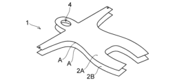
- FIG. 1 is a schematic front view of a garment according to one embodiment (first embodiment) of the present invention.
- FIG. 2 is a schematic exploded view of the garment according to one embodiment of the present invention (first embodiment).
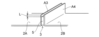
- FIG. 3 is a schematic diagram for explaining the ends and joints of a garment according to one embodiment of the present invention.
- FIG. 4 is a schematic diagram for explaining the ends and joints of a garment according to one embodiment of the present invention.
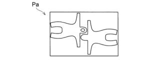
- FIG. 5 is a schematic plan view showing a cutting pattern in the case where the number of cut parts is two.
- FIG. 6 is a schematic plan view showing a cutting pattern in which the number of cut parts is six.
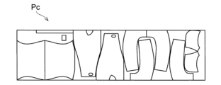
- FIG. 7 is a schematic plan view showing a cutting pattern in which the number of cut parts is 10. As shown in FIG. FIG. FIG.
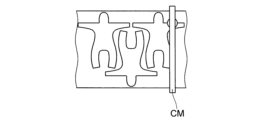
- FIG. 8A is a schematic process diagram for explaining a method for manufacturing a garment according to one embodiment of the present invention.
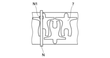
- FIG. 8B is a schematic process diagram for explaining a method for manufacturing a garment according to one embodiment of the present invention.
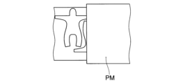
- FIG. 8C is a schematic process diagram for explaining a method for manufacturing a garment according to one embodiment of the present invention.
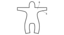
- FIG. 9 is a schematic plan view of a first garment material to which adhesive has been applied.
- FIG. 10 is a schematic plan view showing cutting positions of a first clothing material and a second clothing material.
- FIG. 1 is a schematic front view of a garment 1 according to one embodiment of the present invention (first embodiment).
- FIG. 2 is a schematic exploded view of the garment 1 according to one embodiment of the present invention (first embodiment).
- the garment 1 according to this embodiment includes a body part 2.
- the body part 2 is a part that covers at least one of the upper body or the lower body of a wearer who wears the garment 1.
- the body part 2 includes a plurality of cut parts.
- Each of the cut parts (cut parts 2A constituting the front body part 21 and cut parts 2B constituting the back body part 22) includes an end part A having the same shape.
- the end part A is at least a part of each end part of the cut parts, and the cut parts have a joint part 3 in the vicinity of each end part A joined by an adhesive 5.
- the distance between the outer edge of the cut part and the outer edge of the joint part is 1 to 5 mm.
- the body dimensions of the wearer are not particularly limited.
- a wearer with the following body dimensions is exemplified. That is, the wearer has a height of 171 cm, an upper arm length of 32 cm, a straight neck-acromion distance of 15 cm, a cervical fossa height of 140 cm, a sternal midpoint height of 128 cm, an anterior axillary width of 34 cm, a straight distance between the inferior angles of the scapulae of 20 cm, a thigh length of 44 cm, and a tibial upper border height of 43 cm.
- the use of the garment 1 of this embodiment is not particularly limited.
- the garment 1 is suitable as protective clothing to be worn over the wearer's own clothing when working with dust or radiation or when handling water.
- the garment 1 includes a body portion 2.
- the body portion 2 is a portion that covers at least either the upper or lower body of the wearer who wears the garment 1.
- the garment 1 includes a body portion 2 that covers both the upper and lower body of the wearer.
- the body portion 2 is made up of multiple cut parts.
- the body portion 2 is made up of two cut parts (cut part 2A constituting the front body portion 21 and cut part 2B constituting the back body portion 22).
- the garment 1 has an opening 4 formed at the end of the body portion.
- the opening 4 is a portion for exposing to the outside at least one of the wearer's wrists, ankles, head, face, or torso.
- an example is shown in which the openings 4 are formed at the wearer's wrists, ankles, head, or face.
- the garment 1 can be worn by the wearer.
- the garment 1 may be put on by the wearer inserting the wearer's body into the garment 1 through a back opening (not shown) formed at the back of the garment 1.
- the back opening can be opened and closed by a fastener portion (not shown).
- each of the multiple cut parts has an end A that is the same in shape.
- End A may be at least a portion of the end of each of the multiple cut parts, or may be the entire end of each of the multiple cut parts.
- the shapes of end A are not limited to being completely identical, and may differ as long as the effect of this embodiment is not impaired.
- the shape of end A is within the range of processing error in production, i.e., the ratio of the dimensions of each end A of the cut parts to be joined is within ⁇ 5%, or the ratio of the radii of curvature is within ⁇ 10%, or the angle of end A with respect to the grain is within ⁇ 30°.
- the dimensional ratio of end A here is calculated as the ratio ((dimension of first end A - dimension of second end A) ⁇ (dimension of second end A) x 100 [%]) when the end of the first cut part to be joined is the first end A (or end AA) and the end A of the second cut part is the second end A (or end AB).
- the ratio of the radius of curvature of end A when defined in the same manner as above, is calculated as the ratio ((radius of curvature of first end A - radius of curvature of second end A) ⁇ (radius of curvature of second end A) x 100 [%]).
- the difference in angle between each end A and the grain of the cut parts to be joined is calculated as the angle difference ((first angle - second angle)) when the angle between end A and the grain of the first cut part to be joined is the first angle and the angle between end A and the grain of the second cut part to be joined is the second angle.
- the garment joints are less susceptible to water penetration from the outside, have excellent water resistance, and can be easily produced by automation.
- Figures 3 and 4 are schematic diagrams for explaining the end A and joint of the garment of this embodiment.
- Figure 3 shows an embodiment in which end A1 of one cut part is joined to end A2 of another cut part by 90° adhesion.
- Figure 4 shows an embodiment in which end A3 of one cut part is joined to end A4 of another cut part by 180° adhesion.
- cut parts 2A and 2B have joints 3 near their respective ends A1 and A2, joined by adhesive 5. Also, as shown in FIG. 4, cut parts 2A and 2B have joints 3 near their respective ends A3 and A4, joined by adhesive 5. At joints 3, the distance L between the outer edge of the cut parts and the outer edge of the joints is adjusted to be 1 to 5 mm.
- the distance L between the outer edge of the cut parts and the outer edge of the joint may be 1 to 5 mm, and is preferably 2 to 3 mm. If the distance L between the outer edge of the cut parts and the outer edge of the joint is less than 1 mm, the outer edge of the cut parts will come into contact with the wearer when the garment is worn, and the garment will tend to feel uncomfortable against the skin. On the other hand, if the distance L between the outer edge of the cut parts and the outer edge of the joint exceeds 5 mm, the amount of adhesive 5 that can be applied to the garment is likely to be limited, and a joint of sufficient size 3 will not be formed. As a result, the garment may have a reduced strength or reduced water pressure resistance.
- the adhesive used in this embodiment is not particularly limited.
- the adhesive is preferably at least one adhesive selected from a urethane adhesive, an olefin adhesive, and an epoxy adhesive.
- the urethane adhesive is not particularly limited.
- the urethane adhesive is an adhesive that uses a two-component curing urethane resin that contains various polyol compounds such as polyether polyol, polyester polyol, and acrylic polyol, and a curing agent such as an isocyanate compound.
- the olefin-based adhesive is not particularly limited.
- One example is a polypropylene-based resin.
- Epoxy adhesives may be one-component or two-component.
- One-component epoxy adhesives are room temperature curing or heat curing adhesives containing a latent curing agent such as ketimine, oxazolidine, or aldimine-based compounds, and a liquid epoxy resin.
- two-component epoxy adhesives are adhesives containing a main agent selected from liquid epoxy resins, and a curing agent.
- Liquid epoxy resins include bisphenol A type epoxy resins, bisphenol F type epoxy resins, bisphenol AD type epoxy resins, cresol novolac type epoxy resins, phenol novolac type epoxy resins, ethylene glycol diglycidyl ether, glycerin triglycidyl ether, trimethylolpropane triglycidyl ether, trimethylolethane triglycidyl ether, pentaerythritol tetraglycidyl ether, hydroquinone diglycidyl ether, etc.
- Curing agents include linear aliphatic polyamines, diethylenetriamine, triethylenetetramine, tetraethylenepentamine, dipropylenediamine, diethylaminopropylamine, modified aliphatic polyamines, amine adducts, ketoimines, cyclic aliphatic polyamines, N-aminoethylpiperazine, menthene diamine, isophorone diamine, aromatic amines, m-xylylenediamine, metaphenylenediamine, diaminodiphenylmethane, diaminodiphenylsulfone, polyamidoamines, 2-methylimidazole, 2-ethyl-4-methylimidazole, 1-cyanoethyl-2-undecylimidazolium trimellitate, polythiols, polymercaptans, polysulfides, etc.
- the amount of adhesive is not particularly limited.
- the amount of adhesive applied is preferably 5 g/ m2 or more, more preferably 10 g/ m2 or more, calculated as solid content.
- the amount of adhesive applied is preferably 30 g/ m2 or less, more preferably 20 g/ m2 or less, calculated as solid content.
- the garment has sufficient adhesive strength and is excellent in feel against the skin.
- the adhesive strength at the joint of the garment of this embodiment is preferably 30N or more, and more preferably 80N or more. There is no particular upper limit to the adhesive strength, but a sufficient function can be achieved with a strength of 200N or less. With an adhesive strength within the above range, the garment has sufficient adhesive strength and is excellent in feel against the skin. That is, in the garment of this embodiment, the distance between the outer edge of the cut parts and the outer edge of the joint is 1 to 5 mm, and a sufficient amount of adhesive is applied while maintaining such a distance to form the joint. As a result, the garment is less susceptible to water penetration, has excellent water pressure resistance, and is excellent in feel against the skin when worn by a wearer. In this embodiment, the adhesive strength can be measured in accordance with JIS L 1093-2011 7.3 glove method, with the gripping distance set to 7.6 cm and the pulling speed set to 100 cm/min.
- the water pressure resistance of the garment is preferably 1000 mmH 2 O or more, more preferably 1200 mmH 2 O or more.
- the upper limit of the water pressure resistance is not particularly limited, but a water pressure of 3000 mmH 2 O or less can provide sufficient functionality.
- the garment has sufficient water pressure resistance and excellent skin contact. That is, in the garment of this embodiment, the distance between the outer edge of the cut parts and the outer edge of the joint is 1 to 5 mm, and the joint is formed to exhibit sufficient water pressure resistance while maintaining such a distance.
- the garment is less likely to allow water to penetrate inside, has excellent water pressure resistance, and is excellent in skin contact when worn by a wearer.
- the water pressure resistance can be measured in accordance with the JIS L 1092-2009 low water pressure resistance method, and the pressure increase speed was set to 60 cm/min.
- the fiber material constituting the garment may be a conventionally known fiber material. That is, the fiber material may be polyolefins such as polyethylene and polypropylene, polyesters such as polyethylene terephthalate and polylactic acid, polycarbonate, polystyrene, polyphenylene sulfite, fluorine-based resins, and mixtures of these. Among these, it is preferable that the fiber material be mainly composed of polyolefin-based resins, from the viewpoint of fabric productivity and excellent texture.
- the clothing is preferably made of a nonwoven fabric, and is preferably made of a fabric having a laminated structure of a meltblown nonwoven fabric obtained by the meltblowing method and a spunbonded nonwoven fabric obtained by the spunbonding method, and more preferably made of a laminated nonwoven fabric having a spunbonded nonwoven fabric layer A, a meltblown nonwoven fabric layer, and a spunbonded nonwoven fabric layer B in this order. Since the clothing is made of a nonwoven fabric, the clothing is easy to process, has excellent productivity, and is low cost. Since the clothing is made of the above-mentioned laminated nonwoven fabric, the clothing has sufficient adhesive strength and sufficient water pressure resistance even at the joints.
- the fabric that makes up the clothing may be given properties such as water repellency, oil repellency, antistatic properties, flame retardancy, antibacterial properties, and antifungal properties.
- the spunbonded nonwoven fabric layer A and the meltblown nonwoven fabric layer contain the adhesive in the cross section of the laminated nonwoven fabric at the joint. Furthermore, it is preferable that the amount of the adhesive in the spunbonded nonwoven fabric layer B at the joint is either the first embodiment or the second embodiment described below.
- the spunbond nonwoven fabric B of the first embodiment does not contain any adhesive.
- the ratio of the area of the adhesive contained in the spunbond nonwoven fabric layer B to the total area of the cross section of the spunbond nonwoven fabric layer B in the cross section of the laminated nonwoven fabric at the joint is preferably 5% or less, more preferably 3% or less, and even more preferably 1% or less.
- the amount of the adhesive at the joint is within the above range, so that the spunbonded nonwoven fabric layer A and the meltblown nonwoven fabric layer contain the adhesive, and the spunbonded nonwoven fabric layer B is either the first embodiment or the second embodiment.
- the garment has sufficient adhesive strength and sufficient water pressure resistance even at the joints.
- the garment of this embodiment cut parts having end portions A of the same shape are joined together with an adhesive. Therefore, the resulting garment does not require hand sewing of cut parts of different shapes, and can be produced, for example, by automation. As a result, the garment does not require skilled sewing skills, and the time required for production can be shortened. Furthermore, because the garment is joined with an adhesive, water is less likely to penetrate inside, and the garment has excellent water pressure resistance. Furthermore, in the garment, the distance between the outer edge of the cut parts and the outer edge of the joint is 1 to 5 mm at the joint. Therefore, the garment has excellent skin feel when worn by a wearer.
- the garment of one embodiment of the present invention can be produced by using cut parts cut into a predetermined shape.
- the number of cut parts is preferably 1 to 10, and more preferably 2 to 6.
- 1 to 10 cut parts when cutting parts from a fabric of a predetermined area, the amount of excess fabric after cutting can be reduced while keeping the processing time required for cutting short, resulting in a good yield. Therefore, the garment has better productivity.
- FIG. 5 is a schematic plan view showing cutting pattern Pa when the number of cut parts is two.
- Figure 6 is a schematic plan view showing cutting pattern Pb when the number of cut parts is 6.
- FIG. 7 is a schematic plan view showing a cutting pattern Pc when the number of cut parts is 10.
- processing time refers to the time required from cutting the fabric to the final completion of the garment, that is, the total time including the time to cut the fabric, the time to transport the cut parts, the time to set aside or turn over the cut parts, the time to sew the cut parts, the time to apply adhesive and glue the cut parts, the time to form the openings, and the time to attach auxiliary materials.
- the processing time to make the garment is, for example, about 1100 seconds.
- the length of fabric required per garment is 4.04 m.
- the processing time to make the garment is even longer, for example, about 1700 seconds.
- the length of fabric required per garment is 3.89 m. In this way, as the number of cut parts increases, the number of parts that need to be joined increases, so the processing time increases, but the area of fabric required decreases. Therefore, the number of cut parts can be selected taking into consideration the desired manufacturing time and fabric yield.
- the manufacturing method for clothing according to this embodiment includes a joining process in which adhesive is applied near each end A of a plurality of cut parts, each of which has an end A of the same shape, to form a joint at which the plurality of cut parts are joined by the adhesive.
- the distance between the outer edge of the cut parts at the joint and the outer edge of the joint is 1 to 5 mm.
- End A is at least a part of each end of the plurality of cut parts.
- the manufacturing method for clothing according to this embodiment only needs to include the above-mentioned joining process, and the other processes are not particularly limited.
- an embodiment having a cutting process for cutting the first clothing material 6 and the second clothing material along the outer edge of the joining portion, an opening process for making an opening in at least one area of the wrist, ankle, head, face, or torso of the wearer who will wear the garment, and an inversion process for inverting the front and back of the first clothing material 6 and the second clothing material through the opening is illustrated.
- the cutting process is a process of cutting the first garment material 6 and the second garment material along the outer edge of the joint.
- the operation of the cutting device CM is controlled by a computer (not shown) or the like.
- the cutting device CM is controlled to recognize the area where the adhesive 5 is applied on the first garment material 6 along the cutting line information of the electronic drawing data drawn by a CAD (computer-aided design) system, and to simultaneously cut the first garment material 6 and the second garment material along a line slightly outside the area where the adhesive 5 is applied.
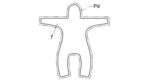
- Fig. 10 is a schematic plan view showing the cutting position Pd of the first garment material 6 and the second garment material.
- the cutting of the first garment material 6 and the second garment material can be performed by placing marking paper with a cutting line on the upper layer of the layered garment material, and manually cutting along the cutting line using scissors, a vertical blade cutter, or a round blade cutter, placing a pattern of the same shape as the parts to be cut on the upper layer of the layered garment material, and manually cutting along the pattern using a band knife, or placing a punching blade of the same shape as the parts to be cut on the upper layer of the layered garment material, and punching and cutting by applying a pressure load. More preferably, a method in which an automatic cutter is used to drive a cutting blade along a cutting line programmed in a computer to cut the garment material is preferable because the processing time of the cutting process is short and the productivity is excellent.
- the first garment material 7 and the second garment material can be layered and cut simultaneously. In this way, by cutting the first clothing material 6 and the second clothing material simultaneously, the end A of the cut parts constituting the first clothing material 6 and the joining line of the end A constituting the second clothing material have the same shape.
- the first garment material 6 and the second garment material are cut so that the distance between the outer edge of the cut part and the outer edge of the joint is 1 to 5 mm.
- the joining process is a process of applying adhesive near the end A of each of a plurality of cut parts (a first clothing material 6 and a second clothing material (not shown)) having end portions A of the same shape, and forming a joint where the plurality of cut parts are joined by the adhesive. Note that it is not necessary to apply adhesive to both the first clothing material 6 and the second clothing material. As in this embodiment, an embodiment may be adopted in which adhesive is applied to the first clothing material 6, and the second clothing material is superimposed on the first clothing material 6 to which adhesive has been applied, so that adhesive is also applied to the second clothing material, and a joint is formed.
- FIG. 9 is a schematic plan view of the first clothing material 6 to which adhesive 5 has been applied.
- adhesive 5 is applied to the fabric corresponding to the first clothing material 6 along the shape of a predetermined joining line.
- the adhesive can be applied by coating, screen printing, lithographic offset printing, inkjet printing, flexographic printing, gravure printing, gravure offset printing, stamping, dispensing, squeegee printing, etc.
- the application of adhesive 5 can be performed by discharging adhesive 5 onto the first garment material 6 while moving the discharge nozzle N1 along the shape of the garment, as shown in FIG. 8B.
- the operation of the discharge nozzle N1 is controlled by a coating device N.
- the operation of the coating nozzle N1 by the coating device N is controlled by a computer (not shown) or the like.
- the coating device N is controlled to recognize the shape of the first garment material 6, and apply adhesive 5 along the shape of the desired joint. In this way, a first garment material 6 to which adhesive 5 has been applied along the shape of the garment is prepared.
- a second garment material (not shown) that has been transported separately is placed on the first garment material 6 to which the adhesive 5 has been applied, and pressed.
- the press processing method is not particularly limited.
- the press processing can be performed by placing the garment material between two metal flat plates and applying pressure, by introducing the garment material between a pair of rolls and applying pressure, or by applying pressure to the garment material between conveyor belts.
- the press processing machine PM supplies the second garment material (not shown) to a position opposite the first garment material 6 to which the adhesive 5 has been applied, and presses the second garment material against the first garment material 6 to bond the first garment material 6 and the second garment material together via the adhesive 5.
- the adhesive is applied to the second garment material along the end A, which has the same shape as the first garment material 6, and a joint is formed.
- the opening step is a step of providing an opening in a part corresponding to at least one of the wrist, an ankle, the head, face, or the torso of a wearer who wears the garment.
- the opening step can form an opening that serves as a starting point for turning the garment inside out in the inversion step described later.
- a part where the joining part 3 is not provided, i.e., a part where the front body part 21 and the back body part 22 are not joined is provided as the opening.
- the location where the opening is formed in the opening process is not particularly limited.
- the location where the opening is formed can be determined by the type and form of the garment. That is, if the garment is a garment consisting of an upper and lower garment, the openings may be formed at positions corresponding to the wearer's wrists, ankles, and neck. On the other hand, if the garment is only a upper garment, the openings may be formed at positions corresponding to the wearer's wrists and neck. In addition, if the garment is equipped with a hood, the openings may be formed to expose the wearer's face. Furthermore, if the garment is a garment worn over underwear, such as protective clothing, a large opening may be formed for the wearer to pass through when wearing it.
- the inversion process is a process of inverting the first garment material 6 and the second garment material through the opening. That is, at the time when the opening is formed in the opening process, the garment is in a state of being cut along the outer edge of the joint. Therefore, at the joint of the first garment material 6 and the second garment material, the end of the garment material is in a state of being exposed so that the distance between the outer edge of the cut part and the outer edge of the joint is 1 to 5 mm. Therefore, by inverting the garment through the opening, the outer periphery of such a garment can be placed on the inside. In this way, the garment 1 of this embodiment (see FIG. 1) can be produced.
- the garment 1 has a portion on the inside of the garment (the side that comes into contact with the wearer's skin) where the first garment material 6 and the second garment material are exposed by 1 to 5 mm.
- a portion is not rigid and feels good against the skin.
- the above-mentioned joining and cutting processes can both be automated by one or more devices equipped with a coating function for applying adhesive, a processing function for supplying and pressing the second garment material, and a cutting function.
- the resulting garment does not require skilled sewing skills, and the time required for manufacturing can be shortened.
- the resulting garment is joined with adhesive, water is less likely to penetrate inside, and the garment has excellent water pressure resistance.
- the distance between the outer edge of the cut parts and the outer edge of the joint is 1 to 5 mm at the joint. Therefore, the resulting garment has excellent skin feel when worn by a wearer.
- the garment is manufactured by carrying out the cutting process, joining process, opening process, and inverting process in that order.
- the garment may be manufactured, for example, by first carrying out the joining process, and then carrying out the opening process and the inverting process.
- the garment of this embodiment may also be manufactured by such a manufacturing method.
- the above describes one embodiment of the present invention.
- the present invention is not particularly limited to the above embodiment.
- the present invention which solves the above problems, mainly includes the following configurations:
- a garment having a body part, the body part being a portion that covers at least either the upper or lower body of a wearer wearing the garment, the body part having a plurality of cut parts, each of the plurality of cut parts having an end part A of the same shape, the end part A being at least a part of each end part of the plurality of cut parts, the plurality of cut parts having joints near each of the end parts A that are joined by adhesive, and at the joints, the distance between the outer edge of the cut parts and the outer edge of the joints is 1 to 5 mm.
- the garment is made by bonding cut parts having end portions A of the same shape together with an adhesive. Therefore, the resulting garment does not require hand sewing of cut parts of different shapes, and can be produced, for example, by automation. As a result, the garment does not require skilled sewing skills, and the time required for production can be shortened. Furthermore, because the garment is bonded with an adhesive, water is less likely to penetrate inside, and the garment has excellent water pressure resistance. Furthermore, at the joints of the garment, the distance between the outer edge of the cut parts and the outer edge of the joints is 1 to 5 mm. Therefore, the garment has excellent skin feel when worn by the wearer.
- the adhesive is at least one adhesive selected from a urethane adhesive, an olefin adhesive, and an epoxy adhesive.
- the adhesive is at least one adhesive selected from a urethane adhesive, an olefin adhesive, and an epoxy adhesive.
- the garment is more likely to have strong joints and has better water pressure resistance.
- the clothing has sufficient adhesive strength and feels good against the skin.
- the garment according to any one of (1) to (4) which is made of a laminated nonwoven fabric having a spunbonded nonwoven fabric layer A, a meltblown nonwoven fabric layer, and a spunbonded nonwoven fabric layer B in this order, wherein in a cross section of the laminated nonwoven fabric at the joint, the spunbonded nonwoven fabric layer A and the meltblown nonwoven fabric layer contain the adhesive, and the spunbonded nonwoven fabric layer B satisfies either of the following (I) or (II).
- the spunbond nonwoven fabric layer B does not contain the adhesive.
- the spunbonded nonwoven fabric layer B contains the adhesive, and the ratio of the area of the adhesive contained in the spunbonded nonwoven fabric layer B to the total area of the cross section of the spunbonded nonwoven fabric layer B in the cross section is 5% or less.
- the garment has sufficient adhesive strength and sufficient water pressure resistance even at the joints.
- the clothing has sufficient adhesive strength and feels good against the skin.
- the clothing has sufficient water pressure resistance and feels great against the skin.
- a method for manufacturing a garment comprising a joining step of applying adhesive to the vicinity of each of a plurality of cut parts having end parts A of the same shape, and forming a joint where the plurality of cut parts are joined by the adhesive, the distance between the outer edge of the cut parts and the outer edge of the joint at the joint being 1 to 5 mm, and the end parts A being at least a part of each of the ends of the plurality of cut parts.
- the resulting garment has cut parts with end portions A of the same shape joined together by adhesive. Therefore, the resulting garment does not require hand sewing of cut parts of different shapes, and can be produced, for example, by automation. As a result, the garment does not require skilled sewing skills, and the time required for production can be shortened. Furthermore, since the resulting garment is joined together by adhesive, water is less likely to penetrate inside, and it has excellent water pressure resistance. Furthermore, in the resulting garment, the distance between the outer edge of the cut parts and the outer edge of the joint is 1 to 5 mm at the joint. Therefore, the resulting garment has excellent skin feel when worn by a wearer.
- Measurements were performed using a TEXTEST FX-3000-IV "Hydrotester" under conditions of a pressure increase rate of 600 mmH2O /min in accordance with JIS L 1092-2009 Method A (low water pressure method), except that the number of drops from near the seams was measured. The water pressure resistance was calculated by taking the average of the three measured values.
- (5) Distance between the outer edge of the garment material and the outer edge of the seam The garment was placed on a flat work bench with the front and back overlapping evenly, and the distance between the tangent to the outer edge of the garment material and the perpendicular edge of the seam was measured at five random points using a tape measure (a tape measure made by Shinwa Sokutei Co., Ltd.).
- the distance between the outer edge of the garment material and the outer edge of the seam was calculated by taking the average value.
- (6) Adhesive strength of joints The fabric was cut at 5 arbitrary points of 100 mm horizontally and 150 mm vertically to the joint direction, centered on the joint of the garment, and measurements were made using an AG-50kNG manufactured by Shimadzu Corporation under conditions of a gripping distance of 7.6 cm and a pulling speed of 100 cm/min in accordance with JIS L 1093-2011 7.3 grab method, and the adhesive strength of the joints was calculated by taking the average value.
- Example 1 A polypropylene melt-blown nonwoven fabric (basis weight 11 g/ m2 ) was directly molded onto one side of a polypropylene spun-bonded nonwoven fabric A (basis weight 18 g/ m2 ) to obtain a laminate. Next, a polypropylene spun-bonded nonwoven fabric B (basis weight 36 g/ m2 ) was directly molded onto the polypropylene melt-blown nonwoven fabric side of this laminate to obtain an SMS laminated nonwoven fabric.
- the SMS laminated nonwoven fabric had a basis weight of 65 g/m 2 and a water pressure resistance of 1150 mmH 2 O.
- a first clothing material and a second clothing material constituting a garment having a hood and comprising an integrated upper and lower garment were cut out from the obtained SMS laminated nonwoven fabric by a method in which an automatic cutting machine was used to drive a cutting blade along a cutting line programmed in a computer to cut the garment material.
- An opening for exposing the wearer's face was formed in the obtained first clothing material, and then a hot melt adhesive (TN-701Z manufactured by MORESCO CORPORATION) was discharged while moving a discharge nozzle along the shape of the garment so that the distance between the outer edge of the first clothing material and the outer edge of the joint was 3 mm and the application amount was 18 g/ m2 .
- a second clothing material that was transported separately was superimposed on the first clothing material to which the adhesive had been applied, and the material was pressed to obtain a clothing material having a front body part and a back body part.
- the water pressure resistance of the joint was 1100 mmH 2 O, and the adhesive strength was 35 N. Furthermore, the spunbonded nonwoven fabric A and the meltblown nonwoven fabric at the joint contained an adhesive, while the spunbonded nonwoven fabric B did not contain an adhesive.
- a zipper (3CFC-120BL manufactured by YKK Corporation) was sewn to the rear body section of the obtained garment material, and then the garment material having a front body section and a rear body section was turned inside out starting from the opening to obtain the garment of Example 1.
- the resulting garment had excellent water resistance, adhesive strength and skin feel.
- Example 2 The garment of Example 2 was obtained in the same manner as in Example 1, except that the distance between the outer edge of the first garment material and the outer edge of the joint was 2 mm.
- the water pressure resistance of the joint of the obtained garment was 1200 mmH2O, and the adhesive strength was 40 N.
- the spunbonded nonwoven fabric A and the meltblown nonwoven fabric at the joint contained an adhesive, while the spunbonded nonwoven fabric B did not contain an adhesive.
- the resulting garment had excellent water resistance, adhesive strength and skin feel.
- Example 3 The garment of Example 3 was obtained in the same manner as in Example 1, except that the distance between the outer edge of the first garment material and the outer edge of the joint was 5 mm.
- the water pressure resistance of the joint of the obtained garment was 1000 mmH2O, and the adhesive strength was 30 N.
- the spunbond nonwoven fabric A and the meltblown nonwoven fabric at the joint contained an adhesive, while the spunbond nonwoven fabric B did not contain an adhesive.
- the resulting garment had excellent water resistance, adhesive strength and skin feel.
- Example 4 The garment of Example 4 was obtained in the same manner as in Example 1, except that the amount of adhesive applied was 3 g/ m2 .
- the water pressure resistance of the joint of the obtained garment was 800 mmH2O, and the adhesive strength was 20 N.
- the spunbonded nonwoven fabric A at the joint contained an adhesive, while the meltblown nonwoven fabric and the spunbonded nonwoven fabric B did not contain an adhesive.
- the resulting garment had sufficient water resistance and adhesive strength, and felt good against the skin.
- Example 5 The garment of Example 5 was obtained in the same manner as in Example 1, except that the amount of adhesive applied was 8 g/ m2 .
- the water pressure resistance of the joint of the obtained garment was 1000 mmH2O, and the adhesive strength was 25 N.
- the spunbonded nonwoven fabric A and the meltblown nonwoven fabric in the joint contained an adhesive, while the spunbonded nonwoven fabric B did not contain an adhesive.
- the resulting garment had excellent water resistance, sufficient adhesive strength and skin comfort.
- Example 6 The garment of Example 6 was obtained in the same manner as in Example 1, except that the amount of adhesive applied was 28 g/ m2 .
- the water pressure resistance of the joints of the obtained garment was 1200 mmH2O , and the adhesive strength was 45 N.
- spunbonded nonwoven fabric A, meltblown nonwoven fabric, and spunbonded nonwoven fabric B at the joints contained adhesive, and the ratio of the area of the adhesive contained in spunbonded nonwoven fabric layer B to the total area of the cross section of spunbonded nonwoven fabric layer B in the cross section of the nonwoven fabrics was 3%.
- the resulting garment had excellent water resistance and adhesive strength, and was comfortable against the skin.
- Example 7 The garment of Example 7 was obtained in the same manner as in Example 1, except that the amount of adhesive applied was 31 g/ m2 .
- the water pressure resistance of the joints of the obtained garment was 1230 mmH2O , and the adhesive strength was 48 N.
- spunbonded nonwoven fabric A, meltblown nonwoven fabric, and spunbonded nonwoven fabric B at the joints contained adhesive, and the ratio of the area of the adhesive contained in spunbonded nonwoven fabric layer B to the total area of the cross section of spunbonded nonwoven fabric layer B in the cross section of the nonwoven fabrics was 7%.
- the resulting garment had excellent water resistance and adhesive strength, and was comfortable against the skin.
- Example 8 A garment of Comparative Example 4 was obtained in the same manner as in Example 1, except that the amount of adhesive applied was 33 g/ m2 .
- the water pressure resistance of the joints of the obtained garment was 1250 mmH2O, and the adhesive strength was 50 N.
- spunbonded nonwoven fabric A, meltblown nonwoven fabric, and spunbonded nonwoven fabric B at the joints contained adhesive, and the ratio of the area of the adhesive contained in spunbonded nonwoven fabric layer B to the total area of the cross section of spunbonded nonwoven fabric layer B in the cross section of the nonwoven fabrics was 10%.
- the resulting garment had excellent water resistance and adhesive strength, and was comfortable against the skin.
- Comparative Example 1 A garment of Comparative Example 1 was obtained in the same manner as in Example 1, except that the distance between the outer edge of the first garment material and the outer edge of the joint was 0 mm.
- the water pressure resistance of the joint of the obtained garment was 1200 mmH2O, and the adhesive strength was 40 N.
- the spunbond nonwoven fabric A and the meltblown nonwoven fabric in the joint contained an adhesive, while the spunbond nonwoven fabric B did not contain an adhesive.
- the resulting garment had excellent water resistance and adhesive strength, but was less comfortable against the skin.
- Comparative Example 2 A garment of Comparative Example 2 was obtained in the same manner as in Example 1, except that the distance between the outer edge of the first garment material and the outer edge of the joint was 6 mm. The water pressure resistance of the joint of the obtained garment was 700 mmH2O, and the adhesive strength was 15 N. In addition, the spunbonded nonwoven fabric A and the meltblown nonwoven fabric in the joint contained an adhesive, while the spunbonded nonwoven fabric B did not contain an adhesive.
- the resulting garment felt good against the skin, but had poor water resistance and adhesive strength.
Landscapes
- Engineering & Computer Science (AREA)
- Textile Engineering (AREA)
- Health & Medical Sciences (AREA)
- General Health & Medical Sciences (AREA)
- Physical Education & Sports Medicine (AREA)
- Details Of Garments (AREA)
Abstract
加工時間を短縮化することができ、かつ、優れた耐水圧を有し、肌当たり性の優れる衣服を提供する。身頃部を備える衣服であり、身頃部は、衣服を着用する着用者の、上半身または下半身のうち少なくともいずれか一方を被覆する部位であり、身頃部は、複数の裁断パーツを有し、複数の裁断パーツの各々は、形状が同一である端部Aを備え、端部Aは、複数の裁断パーツの各々の端部の少なくとも一部であり、複数の裁断パーツが、それぞれの端部Aの近傍において、接着剤によって接合された接合部を有し、接合部において、裁断パーツの外縁部と、接合部の外縁部との距離は、1~5mmである、衣服。
Description
本発明は、衣服に関する。より詳細には、本発明は、加工時間を短縮化することができ、かつ、優れた耐水圧を有し、肌当たり性の優れる衣服に関する。
従来、粉塵や放射線を伴う作業や水を扱う作業において、作業者は、衣服の上に防護服などの衣服を着用して作業することがある。このような用途では、優れた耐水圧が求められる。また、従来、シャツやズボン等の衣服は、生地を縫製することにより作製される。しかしながら、縫製作業は熟練を要し、かつ、製造工程が煩雑である。そこで、衣服を構成するパーツを無縫製で接合した衣服が提案されている(特許文献1参照)。
しかしながら、特許文献1に記載の衣服は、耐水圧に関して改善の余地がある。特に、粉塵や放射線を伴う作業や水を扱う作業においては、特許文献1に記載の衣服では、耐水圧が充分でなく、水が内部に侵入しやすい。また、耐水圧を高めるために、縫製部にシームテープを適用して補強することが考えられる。しかしながら、シームテープで補強した衣服は、肌当たり性が悪い。
本発明は、このような従来の課題に鑑みてなされたものであり、加工時間を短縮化することができ、かつ、優れた耐水圧を有し、肌当たり性の優れる衣服を提供することを目的とする。
上記課題を解決する本発明の一態様の衣服は、身頃部を備える衣服であり、前記身頃部は、前記衣服を着用する着用者の、上半身または下半身のうち少なくともいずれか一方を被覆する部位であり、前記身頃部は、複数の裁断パーツを有し、前記複数の裁断パーツの各々は、形状が同一である端部Aを備え、前記端部Aは、複数の裁断パーツの各々の端部の少なくとも一部であり、前記複数の裁断パーツが、それぞれの前記端部Aの近傍において、接着剤によって接合された接合部を有し、前記接合部において、前記裁断パーツの外縁部と、前記接合部の外縁部との距離は、1~5mmである、衣服である。
上記課題を解決する本発明の一態様の衣服の製造方法は、形状が同一である端部Aを備える、複数の裁断パーツのそれぞれの前記端部Aの近傍に、接着剤を付与し、前記複数の裁断パーツが前記接着剤によって接合された接合部を形成する接合工程、を有し、前記接合部における、前記裁断パーツの外縁部と、前記接合部の外縁部との距離は、1~5mmであり、前記端部Aは、複数の裁断パーツの各々の端部の少なくとも一部である、衣服の製造方法である。
<衣服>
図1は、本発明の一実施形態(第1の実施形態)の衣服1の模式的な正面図である。図2は、本発明の一実施形態(第1の実施形態)の衣服1の模式的な分解図である。本実施形態の衣服1は、身頃部2を備える。身頃部2は、衣服1を着用する着用者の、上半身または下半身のうち少なくともいずれか一方を被覆する部位である。身頃部2は、複数の裁断パーツを有する。複数の裁断パーツ(前身頃部21を構成する裁断パーツ2Aおよび後身頃部22を構成する裁断パーツ2B)の各々は、形状が同一である端部Aを備える。端部Aは、複数の裁断パーツの各々の端部の少なくとも一部であり、複数の裁断パーツが、それぞれの端部Aの近傍において、接着剤5によって接合された接合部3を有する。接合部において、裁断パーツの外縁部と、接合部の外縁部との距離は、1~5mmである。以下、それぞれについて説明する。
図1は、本発明の一実施形態(第1の実施形態)の衣服1の模式的な正面図である。図2は、本発明の一実施形態(第1の実施形態)の衣服1の模式的な分解図である。本実施形態の衣服1は、身頃部2を備える。身頃部2は、衣服1を着用する着用者の、上半身または下半身のうち少なくともいずれか一方を被覆する部位である。身頃部2は、複数の裁断パーツを有する。複数の裁断パーツ(前身頃部21を構成する裁断パーツ2Aおよび後身頃部22を構成する裁断パーツ2B)の各々は、形状が同一である端部Aを備える。端部Aは、複数の裁断パーツの各々の端部の少なくとも一部であり、複数の裁断パーツが、それぞれの端部Aの近傍において、接着剤5によって接合された接合部3を有する。接合部において、裁断パーツの外縁部と、接合部の外縁部との距離は、1~5mmである。以下、それぞれについて説明する。
ここで、本実施形態において、着用者の身体寸法は特に限定されない。本実施形態では、説明の明瞭化のため、以下の身体寸法である着用者が例示される。すなわち、着用者は、身長が171cmであり、上腕長が32cmであり、頸側・肩峰直線距離が15cmであり、頚窩高が140cmであり、胸骨中点高が128cmであり、前腋窩幅が34cmであり、肩甲骨下角間直線距離が20cmであり、大腿長が44cmであり、脛骨上縁高が43cmである。
また、本実施形態の衣服1の用途は特に限定されない。衣服1は、たとえば、粉塵や放射線を伴う作業や水を扱う作業において、着用者が着用している衣服の上に着用する防護服等として好適である。
衣服1は、身頃部2を備える。身頃部2は、衣服1を着用する着用者の、上半身または下半身のうち少なくともいずれか一方を被覆する部位である。本実施形態では、着用者の上半身および下半身の両方を被覆する身頃部2を備える衣服1が例示されている。
図1および図2に示されるように、身頃部2は、複数の裁断パーツからなる。本実施形態では、2つの裁断パーツ(前身頃部21を構成する裁断パーツ2Aおよび後身頃部22を構成する裁断パーツ2B)とからなる態様が例示されている。
衣服1は、身頃部の端部に開口部4が形成されている。開口部4は、着用者の手首、足首、頭部顔面または胴体のうち、少なくともいずれか1か所に相当する部位を、外部に露出するための部位である。本実施形態では、着用者の手首、足首、頭部顔面に開口部4が形成されている態様が例示されている。このような開口部4が形成されていることにより、衣服1は、着用者によって着用され得る。なお、衣服1の着用は、衣服1の背面に形成された背面開口部(図示せず)から、着用者が身体を衣服1内に入れることによって行われてもよい。背面開口部が、ファスナ部(図示せず)によって開閉され得る。
本実施形態において、複数の裁断パーツの各々は、形状が同一である端部Aを備える。端部Aは、複数の裁断パーツの各々の端部の少なくとも一部であればよく、複数の裁断パーツの各々の端部の全体であってもよい。また端部Aの形状は、形状が完全に一致する場合に限らず、本実施形態の効果を損なわない範囲で形状が異なっていてもよい。一例を挙げると、端部Aの形状は、生産における加工誤差範囲内、すなわち接合される裁断パーツ同士の各々の端部Aの寸法の比率がプラスマイナス5%以内、または曲率半径の比率がプラスマイナス10%以内、または地の目に対する端部Aの角度がプラスマイナス30°以内である場合を含む。
ここでいう端部Aの寸法比率とは、接合される裁断パーツ同士のうち、第一の裁断パーツの端部を第一の端部A(または端部AA)とし、第二の裁断パーツの端部Aを第二の端部A(または端部AB)とした場合、比率((第一の端部Aの寸法-第二の端部Aの寸法)÷(第二の端部Aの寸法)×100〔%〕)で求められるものである。端部Aの曲率半径の比率とは、前記同様の定義とした場合、比率((第一の端部Aの曲率半径-第二の端部Aの曲率半径)÷(第二の端部Aの曲率半径)×100〔%〕)で求められるものである。また、接合される裁断パーツ同士の各々の端部Aと地の目との角度の差異とは、接合される第一の裁断パーツの端部Aと地の目との角度を第一の角度、接合される第二の裁断パーツの端部Aと地の目との角度を第二の角度とした場合、角度の差異((第一の角度-第二の角度))で求められるものである。このように、端部Aが、複数の裁断パーツの各々の端部の少なくとも一部であることにより、衣服の接合部は、外部から水が浸入しにくく耐水性が優れ、かつ、オートメーション化により接合部を作製しやすい。
図3および図4は、本実施形態の衣服の端部Aおよび接合部を説明するための模式図である。図3では、1の裁断パーツの端部A1と、他の1の裁断パーツの端部A2とが、90°接着により接合された態様が示されている。一方、図4では、1の裁断パーツの端部A3と、他の1の裁断パーツの端部A4とが、180°接着により接合された態様が示されている。
図3に示されるように、裁断パーツ2Aおよび裁断パーツ2Bは、それぞれの端部A1および端部A2の近傍において、接着剤5によって接合された接合部3を有する。また、図4に示されるように、裁断パーツ2Aおよび裁断パーツ2Bは、それぞれの端部A3および端部A4の近傍において、接着剤5によって接合された接合部3を有する。そして、接合部3において、裁断パーツの外縁部と、接合部の外縁部との距離Lは、1~5mmとなるよう調整されている。
裁断パーツの外縁部と、接合部の外縁部との距離Lは、1~5mmであればよく、2~3mmであることが好ましい。裁断パーツの外縁部と、接合部の外縁部との距離Lが1mm未満である場合、衣服は、着用者が着用した際に、裁断パーツの外縁部が着用者に接し、肌当たりが悪くなる傾向がある。一方、裁断パーツの外縁部と、接合部の外縁部との距離Lが5mmを超える場合、衣服は、付与し得る接着剤5の量が制限されやすく、充分な大きさ3の接合部が形成されない。その結果、衣服は、強度が低下したり、耐水圧が低下するおそれがある。
図3に示される態様(90°接着により接合された態様)によれば、衣服は、接合部の段差が解消され、肌触りがよくなる。一方、図4に示される態様(180°接着により接合された態様)によれば、図3に示される形態と比較すると同じ接着剤の付着量でも接着強度が高くなる。
本実施形態において使用される接着剤は特に限定されない。一例を挙げると、接着剤は、ウレタン系接着剤、オレフィン系接着剤、エポキシ系接着剤から選択される少なくとも1つの接着剤であることが好ましい。これらの接着剤が用いられることにより、衣服は、強固な接合部が形成されやすく、耐水圧がより優れる。
ウレタン系接着剤は特に限定されない。一例を挙げると、ウレタン系接着剤は、ポリエーテルポリオール、ポリエステルポリオール、アクリルポリオール等の各種ポリオール化合物と、イソシアネート化合物等の硬化剤とを含む2液硬化型ウレタン樹脂を利用した接着剤である。
オレフィン系接着剤は特に限定されない。一例を挙げると、オレフィン系接着剤は、ポリプロピレン系樹脂等である。
エポキシ系接着剤は1液型であってもよく、2液型であってもよい。1液型のエポキシ系接着剤は、ケチミンやオキサゾリジン、アルジミン系化合物等の潜在性硬化剤と、液状エポキシ樹脂と、を含む常温硬化または加熱硬化型接着剤等である。一方、2液型のエポキシ系接着剤は、液状のエポキシ樹脂から選ばれる主剤と、硬化剤と、を含有する接着剤である。液状のエポキシ樹脂は、ビスフェノールA型エポキシ樹脂、ビスフェノールF型エポキシ樹脂、ビスフェノールAD型エポキシ樹脂、クレゾールノボラック型エポキシ樹脂、フェノールノボラック型エポキシ樹脂、エチレングリコールジグリシジルエーテル、グリセリントリグリシジルエーテル、トリメチロールプロパントリグリシジルエーテル、トリメチロールエタントリグリシジルエーテル、ペンタエリスリトールテトラグリシジルエーテル、ハイドロキノンジグリシジルエーテル等である。硬化剤は、鎖状脂肪族ポリアミン、ジエチレントリアミン、トリエチレンテトラミン、テトラエチレンペンタミン、ジプロピレンジアミン、ジエチルアミノプロピルアミン、変性脂肪族ポリアミン、アミンアダクト、ケトイミン、環状脂肪族ポリアミン、N-アミノエチルピペラジン、メンセンジアミン、イソホロンジアミン、芳香族アミン、m-キシレンジアミン、メタフェニレンジアミン、ジアミノジフェニルメタン、ジアミノジフェニルスルホン、ポリアミドアミン、2-メチルイミダゾール、2-エチル-4メチルイミダゾール、1-シアノエチル-2-ウンデシルイミダゾリウム・トリメリテート、ポリチオール、ポリメルカプタン、ポリスルフィド等である。
接着剤の量(塗布量)は特に限定されない。一例を挙げると、接着剤の塗布量は、固形分換算で、5g/m2以上であることが好ましく、10g/m2以上であることがより好ましい。一方、接着剤の塗布量は、固形分換算で、30g/m2以下であることが好ましく、20g/m2以下であることがより好ましい。接着剤の量が上記範囲内であることにより、衣服は、充分な接着強度を有し、かつ、肌当たりが優れる。
本実施形態の衣服の接合部における接着強度は、30N以上であることが好ましく、80N以上であることがより好ましい。接着強度の上限は特段制限されるものではないが、200N以下で充分な機能を発現させることができる。接着強度が上記範囲内であることにより、衣服は、充分な接着強度を有し、かつ、肌当たりが優れる。すなわち、本実施形態の衣服は、裁断パーツの外縁部と接合部の外縁部との距離が1~5mmであることに加え、そのような距離を維持しつつ、充分な量の接着剤が付与され、接合部が形成されている。その結果、衣服は、水が内部に入り込みにくく、耐水圧が優れることに加え、着用者が着用した際の肌当たり性が優れる。なお、本実施形態において、接着強度は、JIS L 1093-2011 7.3 グラブ法に順じて測定でき、このとき、掴み間隔を7.6cm、引張速度を100cm/minに設定する。
衣服の耐水圧は、1000mmH2O以上であることが好ましく、1200mmH2O以上であることがより好ましい。耐水圧の上限は特段制限されるものではないが、3000mmH2O以下で充分な機能を発現させることができる。衣服の耐水圧が上記範囲内であることにより、衣服は、充分な耐水圧を有し、かつ、肌当たりが優れる。すなわち、本実施形態の衣服は、裁断パーツの外縁部と接合部の外縁部との距離が1~5mmであることに加え、そのような距離を維持しつつ、充分な耐水圧を示すよう接合部が形成されている。その結果、衣服は、水が内部に入り込みにくく、耐水圧が優れることに加え、着用者が着用した際の肌当たり性が優れる。なお、本実施形態において、耐水圧は、JIS L 1092-2009 低耐水圧法に準じて測定でき、このとき昇圧速度を60cm/minに設定した。
なお、衣服を構成する繊維材料は、従来公知の繊維材料であってよい。すなわち、繊維材料は、ポリエチレン、ポリプロピレン等のポリオレフィン、ポリエチレンテレフタレート、ポリ乳酸等のポリエステル、ポリカーボネート、ポリスチレン、ポリフェニレンサルファイト、フッ素系樹脂、およびこれらの混合物などである。これらの中でも、繊維材料は、生地の生産性や、風合いが優れたものとなる観点から、ポリオレフィン系樹脂を主成分とすることが好ましい。
また、衣服は、不織布からなることが好ましく、メルトブロー法によって得られるメルトブロー不織布と、スパンボンド法により得られるスパンボンド不織布との積層構造からなる生地からなることが好ましく、スパンボンド不織布層A、メルトブロー不織布層、およびスパンボンド不織布層Bを、この順に備える積層不織布からなることがより好ましい。衣服が不織布からなることにより、衣服は、加工等しやすく、生産性が優れるとともに、低コストである。衣服が上記の積層不織布からなることにより、衣服は、充分な接着強度を有し、かつ、接合部においても充分な耐水圧を有する。
なお、衣服を構成する生地は、たとえば、撥水、撥油、帯電防止、難燃、防菌、および防カビ等の機能が付与されてもよい。
衣服を構成する生地が、上記スパンボンド不織布層A、上記メルトブロー不織布層、および上記スパンボンド不織布層Bを、この順に備える積層不織布である場合、上記接合部における上記積層不織布の断面において、上記スパンボンド不織布層Aおよび上記メルトブロー不織布層は、上記接着剤を含有していることが好ましい。さらに、上記接合部における上記スパンボンド不織布層Bの上記接着剤の量は、後述する第1の実施形態および第2の実施形態の何れかであることが好ましい。
ここで、上記第1の実施形態および上記第2の実施形態について、詳細に説明する。
まず、第1の実施形態のスパンボンド不織布Bにおいては、接着剤を含有しない。
また、第2の実施形態のスパンボンド不織布Bにおいては、接着剤を含有し、かつ、上記接合部での上記積層不織布の断面における上記スパンボンド不織布層Bの断面の全面積に対する上記スパンボンド不織布層Bに含有される上記接着剤の面積の割合が5%以下であることが好ましく、3%以下であることがより好ましく、1%以下であることがさらに好ましい。
すなわち、上記接合部における上記接着剤の量は、上記接着剤の量が上記範囲内であることで、上記スパンボンド不織布層Aおよび上記メルトブロー不織布層が上記接着剤を含有し、かつ、上記スパンボンド不織布層Bが上記第1の実施形態または上記第2の実施形態のいずれかとなる。
このような構成によれば、衣服は、充分な接着強度を有し、かつ、接合部においても充分な耐水圧を有する。
以上、本実施形態の衣服は、形状が同一である端部Aを備える裁断パーツ同士が接着剤によって接合される。そのため、得られる衣服は、形状の異なる裁断パーツを手作業で縫製する必要がなく、たとえば、オートメーション化して生産し得る。その結果、衣服は、習熟した縫製技能を必要とせず、かつ、製造に要する時間も短縮化され得る。また、衣服は、接着剤により接合されているため、水が内部に入り込みにくく、耐水圧が優れる。さらに、衣服は、接合部において、裁断パーツの外縁部と、接合部の外縁部との距離が1~5mmである。そのため、衣服は、着用者が着用した際の肌当たり性が優れる。
<衣服の製造方法>
本発明の一実施形態の衣服は、所定の形状に裁断された裁断パーツを用いることにより作製され得る。裁断パーツの数は、1~10であることが好ましく、2~6であることがより好ましい。裁断パーツの数が1~10であることにより、衣服は、所定面積の生地からパーツを裁断する際に、裁断に要する加工時間を短く維持しつつ、裁断後の余った生地の量を少なくすることができ、歩留まりがよい。そのため、衣服は、生産性がより優れる。
本発明の一実施形態の衣服は、所定の形状に裁断された裁断パーツを用いることにより作製され得る。裁断パーツの数は、1~10であることが好ましく、2~6であることがより好ましい。裁断パーツの数が1~10であることにより、衣服は、所定面積の生地からパーツを裁断する際に、裁断に要する加工時間を短く維持しつつ、裁断後の余った生地の量を少なくすることができ、歩留まりがよい。そのため、衣服は、生産性がより優れる。
図5は、裁断パーツ数が2である場合の裁断パターンPaを示す模式的な平面図である。
図6は、裁断パーツ数が6である場合の裁断パターンPbを示す模式的な平面図である。
図7は、裁断パーツ数が10である場合の裁断パターンPcを示す模式的な平面図である。
図5に示されるように、裁断パーツ数が2である場合、接合を要する部位の数が少ない。そのため、衣服を作製するための加工時間は、たとえば、約600秒となる。しかしながら、衣服1着あたりに必要な生地の長さは5.67mとなる。なお、加工時間とは、生地の裁断から衣服を最終的に製造完成するまでに要する時間、すなわち生地の裁断時間と裁断パーツの運搬時間、裁断パーツの取り置きまたは反転作業時間、裁断パーツの縫製時間、裁断パーツの接着剤塗布および接着時間、開口部の形成時間、副資材の取り付け作業時間、これら時間の合計時間をいう。
また、図6に示されるように、裁断パーツ数が6である場合、裁断パーツ数が2である場合と比較して、接合を要する部位の数が増える。そのため、衣服を作製するための加工時間は、たとえば、約1100秒となる。また、衣服1着あたりに必要な生地の長さは4.04mとなる。さらに、図7に示されるように、裁断パーツ数が10である場合、衣服を作製するための加工時間は、さらに長くなり、たとえば、約1700秒となる。一方、衣服1着あたりに必要な生地の長さは3.89mとなる。このように、裁断パーツ数が増えると、接合を要する部位の数が増えるため加工時間が増えるが、必要とされる生地の面積が減る。したがって、裁断パーツ数は、所望する製造時間や、生地の歩留まりを考慮して選択され得る。
図8A~図8Cは、本発明の一実施形態の衣服の製造方法を説明するための模式的な工程図である。本実施形態の衣服の製造方法は、形状が同一である端部Aを備える、複数の裁断パーツのそれぞれの端部Aの近傍に、接着剤を付与し、複数の裁断パーツが接着剤によって接合された接合部を形成する接合工程を有する。接合部における、裁断パーツの外縁部と、接合部の外縁部との距離は、1~5mmである。端部Aは、複数の裁断パーツの各々の端部の少なくとも一部である。以下、それぞれについて説明する。なお、本実施形態では、一例として、裁断パーツ数が2である場合について例示する。また、本実施形態の衣服の製造方法は、上記接合工程を有していればよく、その他の工程は特に限定されない。本実施形態では、一例として、上記接合工程のほか、接合部の外縁に沿って、第1の衣服素材6および第2の衣服素材を裁断する裁断工程と、衣服を着用する着用者の手首、足首、頭部顔面または胴体のうち、少なくともいずれか1か所に相当する部位に開口部を設ける開口工程と、開口部を介して、第1の衣服素材6および第2の衣服素材の表裏を反転させる反転工程と、を有する態様について例示する。
(裁断工程)
裁断工程は、接合部の外縁に沿って、第1の衣服素材6および第2の衣服素材を裁断する工程である。図8Aにおいて、裁断装置CMの動作は、コンピュータ(図示せず)等によって制御されている。たとえば、裁断装置CMは、CADすなわちコンピュータ支援設計システムにより作図された、電子図面データの裁断線情報に沿って、第1の衣服素材6の接着剤5の付与された領域を認識し、接着剤5が付与された領域よりも幾らか外側に沿って、第1の衣服素材6および第2の衣服素材を同時に裁断するよう制御されている。図10は、第1の衣服素材6および第2の衣服素材の裁断位置Pdを示す模式的な平面図である。第1の衣服素材6および第2の衣服素材の裁断は、積層された衣服素材の上層に、裁断線を記したマーキングペーパーを配置し、ハサミ、竪刃裁断機あるいは丸刃裁断機を用いて裁断線に沿って手動で裁断する方法や、積層された衣服素材の上層に、裁断パーツと同一形状の型紙を配置し、バンドナイフを用いて型紙に沿って手動で裁断する方法や、積層された衣服素材の上層に、裁断パーツと同一形状の打ち抜き刃を配置し、押圧荷重をかけて打ち抜き裁断する方法などがある。より好ましくは、自動裁断機を用いて、コンピュータにプログラムされた裁断線に沿って裁断刃が駆動し衣服素材を裁断する方法が、裁断工程の加工時間が短く生産性に優れ好ましい。また、裁断前に行う衣服素材の積層において、第1の衣服素材7と第2の衣服素材とを積層し、同時に裁断することができる。このように、第1の衣服素材6と第2の衣服素材とが同時に裁断されることにより、第1の衣服素材6を構成する裁断パーツの端部Aと、第2の衣服素材を構成する端部Aの接合線とは、同一形状となる。
裁断工程は、接合部の外縁に沿って、第1の衣服素材6および第2の衣服素材を裁断する工程である。図8Aにおいて、裁断装置CMの動作は、コンピュータ(図示せず)等によって制御されている。たとえば、裁断装置CMは、CADすなわちコンピュータ支援設計システムにより作図された、電子図面データの裁断線情報に沿って、第1の衣服素材6の接着剤5の付与された領域を認識し、接着剤5が付与された領域よりも幾らか外側に沿って、第1の衣服素材6および第2の衣服素材を同時に裁断するよう制御されている。図10は、第1の衣服素材6および第2の衣服素材の裁断位置Pdを示す模式的な平面図である。第1の衣服素材6および第2の衣服素材の裁断は、積層された衣服素材の上層に、裁断線を記したマーキングペーパーを配置し、ハサミ、竪刃裁断機あるいは丸刃裁断機を用いて裁断線に沿って手動で裁断する方法や、積層された衣服素材の上層に、裁断パーツと同一形状の型紙を配置し、バンドナイフを用いて型紙に沿って手動で裁断する方法や、積層された衣服素材の上層に、裁断パーツと同一形状の打ち抜き刃を配置し、押圧荷重をかけて打ち抜き裁断する方法などがある。より好ましくは、自動裁断機を用いて、コンピュータにプログラムされた裁断線に沿って裁断刃が駆動し衣服素材を裁断する方法が、裁断工程の加工時間が短く生産性に優れ好ましい。また、裁断前に行う衣服素材の積層において、第1の衣服素材7と第2の衣服素材とを積層し、同時に裁断することができる。このように、第1の衣服素材6と第2の衣服素材とが同時に裁断されることにより、第1の衣服素材6を構成する裁断パーツの端部Aと、第2の衣服素材を構成する端部Aの接合線とは、同一形状となる。
また、裁断工程によれば、第1の衣服素材6および第2の衣服素材の接合部における、裁断パーツの外縁部と、接合部の外縁部との距離が1~5mmとなるよう裁断される。
(接合工程)
接合工程は、形状が同一である端部Aを備える、複数の裁断パーツ(第1の衣服素材6および第2の衣服素材(図示せず)のそれぞれの端部Aの近傍に、接着剤を付与し、複数の裁断パーツが接着剤によって接合された接合部を形成する工程である。なお、接着剤は、第1の衣服素材6および第2の衣服素材の両方に付与する必要はない。本実施形態のように、第1の衣服素材6に接着剤が付与され、接着剤の付与された第1の衣服素材6に対して第2の衣服素材が重ね合わせられることにより、結果的に第2の衣服素材にも接着剤が付与され、接合部が形成される態様であってもよい。
接合工程は、形状が同一である端部Aを備える、複数の裁断パーツ(第1の衣服素材6および第2の衣服素材(図示せず)のそれぞれの端部Aの近傍に、接着剤を付与し、複数の裁断パーツが接着剤によって接合された接合部を形成する工程である。なお、接着剤は、第1の衣服素材6および第2の衣服素材の両方に付与する必要はない。本実施形態のように、第1の衣服素材6に接着剤が付与され、接着剤の付与された第1の衣服素材6に対して第2の衣服素材が重ね合わせられることにより、結果的に第2の衣服素材にも接着剤が付与され、接合部が形成される態様であってもよい。
接合工程では、まず、第1の衣服素材6の形状が示された生地に対し、所望する接合部の形状に沿って、接着剤が付与される。具体的には、接着剤は、第1の衣服7の端部Aの近傍に付与される。図9は、接着剤5が付与された第1の衣服素材6の模式的な平面図である。図9に示されるように、第1の衣服素材6にあたる生地に対し、所定の接合線の形状に沿って、接着剤5が付与される。上記接着剤5を付与する方法は特に限定されない。接着剤の付与は、たとえば、コーティング法、スクリーン印刷法、平版オフセット印刷法、インクジェット法、フレキソ印刷法、グラビア印刷法、グラビアオフセット印刷法、スタンピング法、ディスペンス法、スキージ印刷などを採用できる。
接着剤5の付与は一例を挙げると、図8Bに示されるように、衣服の形状に沿って吐出ノズルN1を移動させながら、接着剤5を第1の衣服素材6に対して吐出することにより実施し得る。図8Bにおいて、吐出ノズルN1は、塗工装置Nによって動作が制御されている。塗工装置Nによる塗工ノズルN1の動作は、コンピュータ(図示せず)等によって制御されている。たとえば、塗工装置Nは、第1の衣服素材6の形状を認識し、所望する接合部の形状に沿って、接着剤5を付与するよう制御されている。これにより、衣服の形状に沿って接着剤5が付与された第1の衣服素材6が準備される。
次いで、図8Cに示されるように、接着剤5の付与された第1の衣服素材6に対し、別途搬送された第2の衣服素材(図示せず)が重ね合わされ、プレス加工される。プレス加工方法は特に限定されない。プレス加工は、たとえば二つの金属平板の間に衣服素材を配して加圧する方法や、一対のロール間に衣服素材を導入して加圧する方法、コンベヤベルト間に衣服素材を加圧する方法を採用することができる。プレス加工機PMは、接着剤5の付与された第1の衣服素材6に対向する位置に第2の衣服素材(図示せず)を供給し、第2の衣服素材を第1の衣服素材6に対してプレス加工することにより、接着剤5を介して第1の衣服素材6と第2の衣服素材とを接合する。これにより、第2の衣服素材に対しても、第1の衣服素材6と同一である形状の端部Aに沿って、接着剤が付与され、接合部が形成される。
(開口工程)
開口工程は、衣服を着用する着用者の手首、足首、頭部顔面または胴体のうち、少なくともいずれか1か所に相当する部位に開口部を設ける工程である。開口工程によれば、後述する反転工程において、表裏を反転させるための起点となる開口部を形成し得る。
衣服に開口部を形成する方法は特に限定されない。一例を挙げると、開口部は、前身頃部21と後身頃部22とを接合部3で接合し身頃部2を形成する際に、接合部3を設けない箇所、すなわち前身頃部21と後身頃部22とが接合されていない箇所を設け、これを開口部とする方法がある。他の例を挙げると、開口部は、予め裁断パーツの内部を切り抜いた後、裁断パーツ同士を接合部3で接合し、前記切り抜き部を開口部として形成する方法がある。
開口工程において開口部が形成される部位は特に限定されない。開口部が形成される部位は、衣服の種類や形態によって決定され得る。すなわち、衣服が上衣および下衣が一体となった衣服である場合には、着用者の手首、足首、頸部に相当する位置に開口部が形成されればよい。一方、衣服が上衣のみである場合には、着用者の手首、頸部に相当する位置に開口部が形成されればよい。ほかにも、フード部を備える衣服である場合には、着用者の顔面を露出するための開口部が形成されればよい。また、衣服は、たとえば防護服のように、肌着などの上から着用される衣服である場合には、着用者が着用時に身体を通すための大きな開口部が形成されてもよい。
(反転工程)
反転工程は、開口部を介して、第1の衣服素材6および第2の衣服素材の表裏を反転させる工程である。すなわち、開口工程において開口部が形成された時点では、衣服は、接合部の外縁に沿って裁断された状態である。そのため、第1の衣服素材6および第2の衣服素材の接合部における、裁断パーツの外縁部と、接合部の外縁部との距離が1~5mmとなるよう、衣服素材の端部が露出した状態である。そこで、衣服は、開口部を介して表裏を反転させることにより、そのような衣服の外周縁を内側に配置させ得る。これにより、本実施形態の衣服1(図1参照)が作製され得る。
反転工程は、開口部を介して、第1の衣服素材6および第2の衣服素材の表裏を反転させる工程である。すなわち、開口工程において開口部が形成された時点では、衣服は、接合部の外縁に沿って裁断された状態である。そのため、第1の衣服素材6および第2の衣服素材の接合部における、裁断パーツの外縁部と、接合部の外縁部との距離が1~5mmとなるよう、衣服素材の端部が露出した状態である。そこで、衣服は、開口部を介して表裏を反転させることにより、そのような衣服の外周縁を内側に配置させ得る。これにより、本実施形態の衣服1(図1参照)が作製され得る。
これにより、衣服1は、衣服の内側(着用者の肌と接する側)において、第1の衣服素材6および第2の衣服素材が1~5mmだけ露出した部分が形成される。しかしながら、このような部分は、剛直ではなく、肌当たりが良好である。
以上、本実施形態の衣服の製造方法では、たとえば、上記した接合工程および裁断工程は、いずれも、接着剤を塗工するための塗工機能、第2の衣服素材を供給し、プレス加工するための加工機能、および、裁断機能等を備える1または複数の装置によってオートメーション化し得る。その結果、得られる衣服は、習熟した縫製技能を必要とせず、かつ、製造に要する時間も短縮化され得る。また、得られる衣服は、接着剤により接合されているため、水が内部に入り込みにくく、耐水圧が優れる。さらに、得られる衣服は、接合部において、裁断パーツの外縁部と、接合部の外縁部との距離が1~5mmである。そのため、得られる衣服は、着用者が着用した際の肌当たり性が優れる。
なお、本実施形態では、裁断工程、接合工程、開口工程、反転工程とが順に実施されることにより衣服が製造される場合について例示した。これに代えて、衣服は、たとえば、最初に接合工程を実施し、その後、開口工程および反転工程を実施してもよい。このような製造方法によっても、本実施形態の衣服は製造され得る。
以上、本発明の一実施形態について説明した。本発明は、上記実施形態に格別限定されない。なお、上記した実施形態は、以下の構成を有する発明を主に説明するものである。
上記課題を解決する本発明には、以下の構成が主に含まれる。
(1)身頃部を備える衣服であり、前記身頃部は、前記衣服を着用する着用者の、上半身または下半身のうち少なくともいずれか一方を被覆する部位であり、前記身頃部は、複数の裁断パーツを有し、前記複数の裁断パーツの各々は、形状が同一である端部Aを備え、前記端部Aは、複数の裁断パーツの各々の端部の少なくとも一部であり、前記複数の裁断パーツが、それぞれの前記端部Aの近傍において、接着剤によって接合された接合部を有し、前記接合部において、前記裁断パーツの外縁部と、前記接合部の外縁部との距離は、1~5mmである、衣服。
このような構成によれば、衣服は、形状が同一である端部Aを備える裁断パーツ同士が接着剤によって接合される。そのため、得られる衣服は、形状の異なる裁断パーツを手作業で縫製する必要がなく、たとえば、オートメーション化して生産し得る。その結果、衣服は、習熟した縫製技能を必要とせず、かつ、製造に要する時間も短縮化され得る。また、衣服は、接着剤により接合されているため、水が内部に入り込みにくく、耐水圧が優れる。さらに、衣服は、接合部において、裁断パーツの外縁部と、接合部の外縁部との距離が1~5mmである。そのため、衣服は、着用者が着用した際の肌当たり性が優れる。
(2)前記接着剤は、ウレタン系接着剤、オレフィン系接着剤、エポキシ系接着剤から選択される少なくとも1つの接着剤である請求項1記載の衣服、(1)記載の衣服。
このような構成によれば、衣服は、強固な接合部が形成されやすく、耐水圧がより優れる。
(3)不織布からなる、(1)または(2)記載の衣服。
このような構成によれば、衣服は、加工等しやすく、生産性が優れるとともに、低コストである。
(4)前記接着剤の量は、5~30g/m2である、(1)~(3)のいずれかに記載の衣服。
このような構成によれば、衣服は、充分な接着強度を有し、かつ、肌当たりが優れる。
(5)スパンボンド不織布層A、メルトブロー不織布層、およびスパンボンド不織布層Bを、この順に備える積層不織布からなり、前記接合部における前記積層不織布の断面において、前記スパンボンド不織布層Aおよび前記メルトブロー不織布層は、前記接着剤を含有しており、前記スパンボンド不織布層Bは、以下の(I)および(II)の何れかを充足する、(1)~(4)のいずれかに記載の衣服。
(I)前記スパンボンド不織布層Bは、前記接着剤を含有しない。
(II)前記スパンボンド不織布層Bは、前記接着剤を含有し、かつ、前記断面における前記スパンボンド不織布層Bの断面の全面積に対する前記スパンボンド不織布層Bに含有される前記接着剤の面積の割合が5%以下である。
(I)前記スパンボンド不織布層Bは、前記接着剤を含有しない。
(II)前記スパンボンド不織布層Bは、前記接着剤を含有し、かつ、前記断面における前記スパンボンド不織布層Bの断面の全面積に対する前記スパンボンド不織布層Bに含有される前記接着剤の面積の割合が5%以下である。
このような構成によれば、衣服は、充分な接着強度を有し、かつ、接合部においても充分な耐水圧を有する。
(6)接着強度は、30N以上である、(1)~(5)のいずれかに記載の衣服。
このような構成によれば、衣服は、充分な接着強度を有し、かつ、肌当たりが優れる。
(7)耐水圧は、1000mmH2O以上である、(1)~(6)のいずれかに記載の衣服。
このような構成によれば、衣服は、充分な耐水圧を有し、かつ、肌当たりが優れる。
(8)形状が同一である端部Aを備える、複数の裁断パーツのそれぞれの前記端部Aの近傍に、接着剤を付与し、前記複数の裁断パーツが前記接着剤によって接合された接合部を形成する接合工程、を有し、前記接合部における、前記裁断パーツの外縁部と、前記接合部の外縁部との距離は、1~5mmであり、前記端部Aは、複数の裁断パーツの各々の端部の少なくとも一部である、衣服の製造方法。
このような構成によれば、得られる衣服は、形状が同一である端部Aを備える裁断パーツ同士が接着剤によって接合される。そのため、得られる衣服は、形状の異なる裁断パーツを手作業で縫製する必要がなく、たとえば、オートメーション化して生産し得る。その結果、衣服は、習熟した縫製技能を必要とせず、かつ、製造に要する時間も短縮化され得る。また、得られる衣服は、接着剤により接合されているため、水が内部に入り込みにくく、耐水圧が優れる。さらに、得られる衣服は、接合部において、裁断パーツの外縁部と、接合部の外縁部との距離が1~5mmである。そのため、得られる衣服は、着用者が着用した際の肌当たり性が優れる。
以下、実施例により本発明をより具体的に説明する。なお、本発明は、これら実施例に何ら限定されない。
[測定方法]
(1)生地の目付
衣服に使用されている生地の任意の箇所2点を200mm×200mm角にカットして質量を測定し、1m2当たりの質量に換算して平均値を取ることで目付を算出した。
(2)接着剤の量
衣服の直線状の接合部を含む生地の任意の箇所2点を接合部の形状に沿って長さ50mmでカットして質量を測定し、1m2当たりの質量に換算し、以下(I)式を用いて接着剤の塗布量を算出した。
(衣服の接合部を含む生地の1m2当たりの質量)―(衣服の生地の目付)×2・・・(I)
(3)接合部を含まない生地の耐水圧
衣服に使用されている生地の接合部を含まない任意の箇所3点を150mm×150mm角にカットし、JIS L 1092―2009 A法(低水圧法)に準じて、昇圧速度600mmH2O/分の条件下で、TEXTEST社製FX-3000-IV「ハイドロテスター」を用いて測定して、3つの測定値の平均値を取ることで耐水圧を算出した。
(4)接合部を含む生地の耐水圧
衣服の接合部を含む生地の任意の箇所3点を接合部が中心に位置するように150mm×150mm角にカットし、測定位置の中心に接合部が位置するようにサンプルを設置して、接合部付近からの出滴数を計測すること以外はJIS L 1092-2009 A法(低水圧法)に準じて、昇圧速度600mmH2O/分の条件下で、TEXTEST社製FX-3000-IV「ハイドロテスター」を用いて測定して、3つの測定値の平均値を取ることで耐水圧を算出した。
(5)衣服素材の外縁部と接合部の外縁部との距離
衣服を前面と背面が均等に重なった状態となるように、平坦な作業台の上に静置し、衣服素材の外縁部の接線と接合部の外縁部に対して垂直方向の距離を任意の箇所5点についてメジャー(シンワ測定(株)製テープメジャー)を用いて測定し、平均値を取ることで衣服素材の外縁部と接合部の外縁部との距離を算出した。
(6)接合部の接着強度
衣服の接合部を中心に、接合方向に対して水平に100mm、垂直に150mmの生地を任意の箇所5点カットし、JIS L 1093-2011 7.3 グラブ法に準じて、掴み間隔7.6cm、引張速度100cm/minの条件で、(株)島津製作所製AG-50kNGを用いて測定、平均値を取ることで接合部の接着強度を算出した。
(7)不織布断面におけるスパンボンド不織布層Bの断面の全面積に対するスパンボンド不織布層Bに含有される接着剤の面積の割合
衣服を構成する生地を、片刃剃刀を用いて、生地の面と垂直な面で切断した。生地の切断面の任意の箇所3点を、(株)キーエンス製VR-3200を用いて撮影し、スパンボンド不織布層B全体の面積およびスパンボンド不織布層Bに含まれる接着剤の面積をそれぞれ計測し、得られた計測値からスパンボンド不織布層Bの断面の全面積に対するスパンボンド不織布層Bに含有される接着剤の面積の割合を算出し、算出した値の平均値を取ることで不織布断面におけるスパンボンド不織布層Bの断面の全面積に対するスパンボンド不織布層Bに含有される接着剤の面積の割合を算出した。
(8)肌当たり性
衣服を着用し、接合部の肌当たり性を評価した。
<評価基準>
・○:肌当たり性に優れていた。
・△:肌当たり性は充分であったが、長時間着用には向かなかった。
・×:肌当たり性は劣っていた。
[実施例1]
ポリプロピレン製のスパンボンド不織布A(目付18g/m2)の一方の面上に、ポリプロピレン製のメルトブロー不織布(目付11g/m2)を直接成形し積層体を得た。次に、この積層体のポリプロピレン製のメルトブロー不織布側の面上にポリプロピレン製のスパンボンド不織布B(目付36g/m2)を直接成形し、SMS積層不織布を得た。
ポリプロピレン製のスパンボンド不織布A(目付18g/m2)の一方の面上に、ポリプロピレン製のメルトブロー不織布(目付11g/m2)を直接成形し積層体を得た。次に、この積層体のポリプロピレン製のメルトブロー不織布側の面上にポリプロピレン製のスパンボンド不織布B(目付36g/m2)を直接成形し、SMS積層不織布を得た。
上記SMS積層不織布の目付は65g/m2、耐水圧は1150mmH2Oであった。
自動裁断機を用いて、コンピュータにプログラムされた裁断線に沿って裁断刃が駆動し衣服素材を裁断する方法によって、得られたSMS積層不織布から、フードを有し、上衣と下衣が一体となった衣服を構成する第1の衣服素材および第2の衣服素材を切り抜いた。得られた第1の衣服素材に対して、着用者の顔面を露出するための開口部を形成した後に、衣服の形状に沿って吐出ノズルを移動させながら、上記第1の衣服素材の外縁部と接合部の外縁部との距離が3mm、塗布量が18g/m2となるようにホットメルト接着剤((株)MORESCO製TN-701Z)を吐出し、接着剤の付与された第1の衣服素材に対し、別途搬送された第2の衣服素材を重ね合わせ、プレス加工することで、前身頃部および後身頃部を有する衣服素材を得た。
接合部の耐水圧は1100mmH2Oであり、接着強度は35Nであった。また、接合部におけるスパンボンド不織布Aおよびメルトブロー不織布は接着剤を含有し、スパンボンド不織布Bは接着剤を含有していなかった。
さらに、得られた衣服素材の後身頃部にファスナー(YKK(株)製3CFC-120BL)を縫合し、次いで、前身頃部および後身頃部を有する衣服素材を開口部を起点として表裏を反転させることで実施例1の衣服を得た。
得られた衣服は、耐水性、接着強度および肌当たり性が優れた。
[実施例2]
第1の衣服素材の外縁部と接合部の外縁部との距離を2mmとした以外は実施例1と同様にして実施例2の衣服を得た。得られた衣服の接合部の耐水圧は1200mmH2Oであり、接着強度は40Nであった。また、接合部におけるスパンボンド不織布Aおよびメルトブロー不織布は接着剤を含有し、スパンボンド不織布Bは接着剤を含有していなかった。
第1の衣服素材の外縁部と接合部の外縁部との距離を2mmとした以外は実施例1と同様にして実施例2の衣服を得た。得られた衣服の接合部の耐水圧は1200mmH2Oであり、接着強度は40Nであった。また、接合部におけるスパンボンド不織布Aおよびメルトブロー不織布は接着剤を含有し、スパンボンド不織布Bは接着剤を含有していなかった。
得られた衣服は、耐水性、接着強度および肌当たり性が優れた。
[実施例3]
第1の衣服素材の外縁部と接合部の外縁部との距離を5mmとした以外は実施例1と同様にして実施例3の衣服を得た。得られた衣服の接合部の耐水圧は1000mmH2Oであり、接着強度は30Nであった。また、接合部におけるスパンボンド不織布Aおよびメルトブロー不織布は接着剤を含有し、スパンボンド不織布Bは接着剤を含有していなかった。
第1の衣服素材の外縁部と接合部の外縁部との距離を5mmとした以外は実施例1と同様にして実施例3の衣服を得た。得られた衣服の接合部の耐水圧は1000mmH2Oであり、接着強度は30Nであった。また、接合部におけるスパンボンド不織布Aおよびメルトブロー不織布は接着剤を含有し、スパンボンド不織布Bは接着剤を含有していなかった。
得られた衣服は、耐水性、接着強度および肌当たり性が優れた。
[実施例4]
接着剤の塗布量を3g/m2とした以外は実施例1と同様にして実施例4の衣服を得た。得られた衣服の接合部の耐水圧は800mmH2Oであり、接着強度は20Nであった。また、接合部におけるスパンボンド不織布Aは接着剤を含有し、メルトブロー不織布およびスパンボンド不織布Bは接着剤を含有していなかった。
接着剤の塗布量を3g/m2とした以外は実施例1と同様にして実施例4の衣服を得た。得られた衣服の接合部の耐水圧は800mmH2Oであり、接着強度は20Nであった。また、接合部におけるスパンボンド不織布Aは接着剤を含有し、メルトブロー不織布およびスパンボンド不織布Bは接着剤を含有していなかった。
得られた衣服は、耐水性および接着強度は充分であり、肌当たり性が優れた。
[実施例5]
接着剤の塗布量を8g/m2とした以外は実施例1と同様にして実施例5の衣服を得た。得られた衣服の接合部の耐水圧は1000mmH2Oであり、接着強度は25Nであった。また、接合部におけるスパンボンド不織布Aおよびメルトブロー不織布は接着剤を含有し、スパンボンド不織布Bは接着剤を含有していなかった。
接着剤の塗布量を8g/m2とした以外は実施例1と同様にして実施例5の衣服を得た。得られた衣服の接合部の耐水圧は1000mmH2Oであり、接着強度は25Nであった。また、接合部におけるスパンボンド不織布Aおよびメルトブロー不織布は接着剤を含有し、スパンボンド不織布Bは接着剤を含有していなかった。
得られた衣服は、耐水性が優れ、接着強度および肌当たり性が充分であった。
[実施例6]
接着剤の塗布量を28g/m2とした以外は実施例1と同様にして実施例6の衣服を得た。得られた衣服の接合部の耐水圧は1200mmH2Oであり、接着強度は45Nであった。また、接合部におけるスパンボンド不織布A、メルトブロー不織布およびスパンボンド不織布Bは接着剤を含有し、かつ、不織布断面におけるスパンボンド不織布層Bの断面の全面積に対するスパンボンド不織布層Bに含有される接着剤の面積の割合が3%であった。
接着剤の塗布量を28g/m2とした以外は実施例1と同様にして実施例6の衣服を得た。得られた衣服の接合部の耐水圧は1200mmH2Oであり、接着強度は45Nであった。また、接合部におけるスパンボンド不織布A、メルトブロー不織布およびスパンボンド不織布Bは接着剤を含有し、かつ、不織布断面におけるスパンボンド不織布層Bの断面の全面積に対するスパンボンド不織布層Bに含有される接着剤の面積の割合が3%であった。
得られた衣服は、耐水性および接着強度が優れ、肌当たり性が充分であった。
[実施例7]
接着剤の塗布量を31g/m2とした以外は実施例1と同様にして実施例7の衣服を得た。得られた衣服の接合部の耐水圧は1230mmH2Oであり、接着強度は48Nであった。また、接合部におけるスパンボンド不織布A、メルトブロー不織布およびスパンボンド不織布Bは接着剤を含有し、かつ、不織布断面におけるスパンボンド不織布層Bの断面の全面積に対するスパンボンド不織布層Bに含有される接着剤の面積の割合が7%であった。
接着剤の塗布量を31g/m2とした以外は実施例1と同様にして実施例7の衣服を得た。得られた衣服の接合部の耐水圧は1230mmH2Oであり、接着強度は48Nであった。また、接合部におけるスパンボンド不織布A、メルトブロー不織布およびスパンボンド不織布Bは接着剤を含有し、かつ、不織布断面におけるスパンボンド不織布層Bの断面の全面積に対するスパンボンド不織布層Bに含有される接着剤の面積の割合が7%であった。
得られた衣服は、耐水性および接着強度が優れ、肌当たり性が充分であった。
[実施例8]
接着剤の塗布量を33g/m2とした以外は実施例1と同様にして比較例4の衣服を得た。得られた衣服の接合部の耐水圧は1250mmH2Oであり、接着強度は50Nであった。また、接合部におけるスパンボンド不織布A、メルトブロー不織布およびスパンボンド不織布Bは接着剤を含有し、かつ、不織布断面におけるスパンボンド不織布層Bの断面の全面積に対するスパンボンド不織布層Bに含有される接着剤の面積の割合が10%であった。
接着剤の塗布量を33g/m2とした以外は実施例1と同様にして比較例4の衣服を得た。得られた衣服の接合部の耐水圧は1250mmH2Oであり、接着強度は50Nであった。また、接合部におけるスパンボンド不織布A、メルトブロー不織布およびスパンボンド不織布Bは接着剤を含有し、かつ、不織布断面におけるスパンボンド不織布層Bの断面の全面積に対するスパンボンド不織布層Bに含有される接着剤の面積の割合が10%であった。
得られた衣服は、耐水性および接着強度が優れ、肌当たり性が充分であった。
[比較例1]
第1の衣服素材の外縁部と接合部の外縁部との距離を0mmとした以外は実施例1と同様にして比較例1の衣服を得た。得られた衣服の接合部の耐水圧は1200mmH2Oであり、接着強度は40Nであった。また、接合部におけるスパンボンド不織布Aおよびメルトブロー不織布は接着剤を含有し、スパンボンド不織布Bは接着剤を含有していなかった。
第1の衣服素材の外縁部と接合部の外縁部との距離を0mmとした以外は実施例1と同様にして比較例1の衣服を得た。得られた衣服の接合部の耐水圧は1200mmH2Oであり、接着強度は40Nであった。また、接合部におけるスパンボンド不織布Aおよびメルトブロー不織布は接着剤を含有し、スパンボンド不織布Bは接着剤を含有していなかった。
得られた衣服は、耐水性および接着強度が優れたが、肌当たり性が劣った。
[比較例2]
第1の衣服素材の外縁部と接合部の外縁部との距離を6mmとした以外は実施例1と同様にして比較例2の衣服を得た。得られた衣服の接合部の耐水圧は700mmH2Oであり、接着強度は15Nであった。また、接合部におけるスパンボンド不織布Aおよびメルトブロー不織布は接着剤を含有し、スパンボンド不織布Bは接着剤を含有していなかった。
第1の衣服素材の外縁部と接合部の外縁部との距離を6mmとした以外は実施例1と同様にして比較例2の衣服を得た。得られた衣服の接合部の耐水圧は700mmH2Oであり、接着強度は15Nであった。また、接合部におけるスパンボンド不織布Aおよびメルトブロー不織布は接着剤を含有し、スパンボンド不織布Bは接着剤を含有していなかった。
得られた衣服は、肌当たり性に優れたが、耐水性および接着強度が劣った。
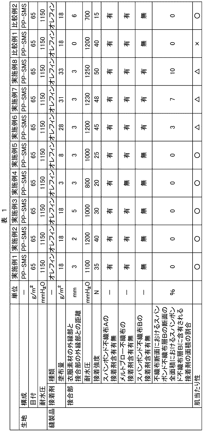
以下の表1に、上記実施例および比較例の結果を示す。
1 衣服
2 身頃部
21 前身頃部
22 後身頃部
2A、2B 裁断パーツ
3 接合部
4 開口部
5 接着剤
6 第1の衣服素材
A、A1、A2、A3、A4 端部
CM 裁断装置
L 裁断パーツの外縁部と接合部の外縁部との距離
N 塗工装置
N1 吐出ノズル
PM プレス加工機
Pa、Pb、Pc 裁断パターン
2 身頃部
21 前身頃部
22 後身頃部
2A、2B 裁断パーツ
3 接合部
4 開口部
5 接着剤
6 第1の衣服素材
A、A1、A2、A3、A4 端部
CM 裁断装置
L 裁断パーツの外縁部と接合部の外縁部との距離
N 塗工装置
N1 吐出ノズル
PM プレス加工機
Pa、Pb、Pc 裁断パターン
Claims (8)
- 身頃部を備える衣服であり、
前記身頃部は、前記衣服を着用する着用者の、上半身または下半身のうち少なくともいずれか一方を被覆する部位であり、
前記身頃部は、複数の裁断パーツを有し、
前記複数の裁断パーツの各々は、形状が同一である端部Aを備え、
前記端部Aは、複数の裁断パーツの各々の端部の少なくとも一部であり、
前記複数の裁断パーツが、それぞれの前記端部Aの近傍において、接着剤によって接合された接合部を有し、
前記接合部において、前記裁断パーツの外縁部と、前記接合部の外縁部との距離は、1~5mmである、衣服。 - 前記接着剤は、ウレタン系接着剤、オレフィン系接着剤、エポキシ系接着剤から選択される少なくとも1つの接着剤である請求項1記載の衣服、請求項1記載の衣服。
- 不織布からなる、請求項1または2記載の衣服。
- 前記接着剤の量は、5~30g/m2である、請求項1または2記載の衣服。
- スパンボンド不織布層A、メルトブロー不織布層、およびスパンボンド不織布層Bを、この順に備える積層不織布からなり、
前記接合部における前記積層不織布の断面において、前記スパンボンド不織布層Aおよびメルトブロー不織布層は、前記接着剤を含有しており、
前記スパンボンド不織布層Bは、以下の(I)および(II)の何れかを充足する、請求項4記載の衣服。
(I)前記スパンボンド不織布層Bは、前記接着剤を含有しない。
(II)前記スパンボンド不織布層Bは、前記接着剤を含有し、かつ、前記断面における前記スパンボンド不織布層Bの断面の全面積に対する前記スパンボンド不織布層Bに含有される前記接着剤の面積の割合が5%以下である。 - 接着強度は、30N以上である、請求項1または2記載の衣服。
- 耐水圧は、1000mmH2O以上である、請求項1または2記載の衣服。
- 形状が同一である端部Aを備える、複数の裁断パーツのそれぞれの前記端部Aの近傍に、接着剤を付与し、前記複数の裁断パーツが前記接着剤によって接合された接合部を形成する接合工程、を有し、
前記接合部における、前記裁断パーツの外縁部と、前記接合部の外縁部との距離は、1~5mmであり、
前記端部Aは、複数の裁断パーツの各々の端部の少なくとも一部である、衣服の製造方法。
Applications Claiming Priority (2)
| Application Number | Priority Date | Filing Date | Title |
|---|---|---|---|
| JP2022-179095 | 2022-11-08 | ||
| JP2022179095 | 2022-11-08 |
Publications (1)
| Publication Number | Publication Date |
|---|---|
| WO2024101092A1 true WO2024101092A1 (ja) | 2024-05-16 |
Family
ID=91032809
Family Applications (1)
| Application Number | Title | Priority Date | Filing Date |
|---|---|---|---|
| PCT/JP2023/037591 Ceased WO2024101092A1 (ja) | 2022-11-08 | 2023-10-17 | 衣服 |
Country Status (2)
| Country | Link |
|---|---|
| JP (1) | JP2024068645A (ja) |
| WO (1) | WO2024101092A1 (ja) |
Families Citing this family (1)
| Publication number | Priority date | Publication date | Assignee | Title |
|---|---|---|---|---|
| WO2026141542A1 (ja) * | 2024-12-27 | 2026-07-02 | 株式会社瑞光 | 衣服及び衣服の製造方法 |
Citations (4)
| Publication number | Priority date | Publication date | Assignee | Title |
|---|---|---|---|---|
| US20020002938A1 (en) * | 2000-06-07 | 2002-01-10 | Alberts Joseph Richard | 1Process for manufacturing shirts with inset sleeves |
| JP2002227013A (ja) * | 2001-02-01 | 2002-08-14 | Uni Charm Corp | 使い捨てガーメントの製造方法 |
| JP2015140494A (ja) * | 2014-01-28 | 2015-08-03 | 有限会社中田久吉商店 | 無縫の衣類 |
| JP2017222969A (ja) * | 2016-06-09 | 2017-12-21 | 株式会社金星 | 無縫製衣服 |
-
2023
- 2023-10-17 WO PCT/JP2023/037591 patent/WO2024101092A1/ja not_active Ceased
- 2023-10-31 JP JP2023186774A patent/JP2024068645A/ja active Pending
Patent Citations (4)
| Publication number | Priority date | Publication date | Assignee | Title |
|---|---|---|---|---|
| US20020002938A1 (en) * | 2000-06-07 | 2002-01-10 | Alberts Joseph Richard | 1Process for manufacturing shirts with inset sleeves |
| JP2002227013A (ja) * | 2001-02-01 | 2002-08-14 | Uni Charm Corp | 使い捨てガーメントの製造方法 |
| JP2015140494A (ja) * | 2014-01-28 | 2015-08-03 | 有限会社中田久吉商店 | 無縫の衣類 |
| JP2017222969A (ja) * | 2016-06-09 | 2017-12-21 | 株式会社金星 | 無縫製衣服 |
Also Published As
| Publication number | Publication date |
|---|---|
| JP2024068645A (ja) | 2024-05-20 |
Similar Documents
| Publication | Publication Date | Title |
|---|---|---|
| EP2445718B1 (en) | A method of manufacturing a flexible, impact-resistant material | |
| US3869726A (en) | Glove liner and glove comprising such liner | |
| US20100011484A1 (en) | Knit fabric gloves and other knit articles with improved grip/protective surfaces | |
| US20180361676A1 (en) | Systems and methods for forming adhesive bonds | |
| EP2084004A1 (en) | A method of manufacturing a flexible, impact- resistant laminate | |
| EA028487B1 (ru) | Амортизирующий щиток | |
| JP2024068645A (ja) | 衣服 | |
| TWM243955U (en) | Disposable clothes for surgery operation | |
| US10870778B2 (en) | Elastomeric tape with enhanced stretch characteristics | |
| JP2019173265A (ja) | 手袋及び該手袋の製造方法 | |
| US20110171881A1 (en) | Method for joining fabric panels and manufacturing brassieres | |
| EP3373757B1 (en) | Athletic bib | |
| CN107280079A (zh) | 一种可脱卸衣领式衬衫 | |
| JP2024068644A (ja) | 衣服 | |
| WO2020243923A1 (en) | Method of manufacturing an article of clothing | |
| TW457076B (en) | Disposable upper garment and process for making the same | |
| WO2007143928A1 (en) | Method for joining fabric panels and manufacturing brassieres | |
| US11745460B2 (en) | 3D embossed film | |
| CN107538830A (zh) | 一种复合面料以及该面料的生产工艺 | |
| WO2018224845A1 (en) | Fabric and method of making a fabric | |
| JP7832962B2 (ja) | 細長い開口部を有する複合材料 | |
| JP2024111736A (ja) | 防護服 | |
| JP2013234403A (ja) | 重量物運搬に適した衣類 | |
| EP1633921B1 (en) | Process for obtaining a fused seam for pieces of fabric | |
| JP2024037094A (ja) | 伸縮性積層体の製造方法 |
Legal Events
| Date | Code | Title | Description |
|---|---|---|---|
| 121 | Ep: the epo has been informed by wipo that ep was designated in this application |
Ref document number: 23888444 Country of ref document: EP Kind code of ref document: A1 |
|
| NENP | Non-entry into the national phase |
Ref country code: DE |
|
| 122 | Ep: pct application non-entry in european phase |
Ref document number: 23888444 Country of ref document: EP Kind code of ref document: A1 |