WO2024100970A1 - クランプ装置並びにその制御方法及び制御プログラム - Google Patents
クランプ装置並びにその制御方法及び制御プログラム Download PDFInfo
- Publication number
- WO2024100970A1 WO2024100970A1 PCT/JP2023/031523 JP2023031523W WO2024100970A1 WO 2024100970 A1 WO2024100970 A1 WO 2024100970A1 JP 2023031523 W JP2023031523 W JP 2023031523W WO 2024100970 A1 WO2024100970 A1 WO 2024100970A1
- Authority
- WO
- WIPO (PCT)
- Prior art keywords
- pair
- voltage
- component
- arms
- closed state
- Prior art date
- Legal status (The legal status is an assumption and is not a legal conclusion. Google has not performed a legal analysis and makes no representation as to the accuracy of the status listed.)
- Ceased
Links
Images




Classifications
-
- H—ELECTRICITY
- H10—SEMICONDUCTOR DEVICES; ELECTRIC SOLID-STATE DEVICES NOT OTHERWISE PROVIDED FOR
- H10W—GENERIC PACKAGES, INTERCONNECTIONS, CONNECTORS OR OTHER CONSTRUCTIONAL DETAILS OF DEVICES COVERED BY CLASS H10
- H10W72/00—Interconnections or connectors in packages
- H10W72/071—Connecting or disconnecting
- H10W72/0711—Apparatus therefor
-
- B—PERFORMING OPERATIONS; TRANSPORTING
- B23—MACHINE TOOLS; METAL-WORKING NOT OTHERWISE PROVIDED FOR
- B23K—SOLDERING OR UNSOLDERING; WELDING; CLADDING OR PLATING BY SOLDERING OR WELDING; CUTTING BY APPLYING HEAT LOCALLY, e.g. FLAME CUTTING; WORKING BY LASER BEAM
- B23K20/00—Non-electric welding by applying impact or other pressure, with or without the application of heat, e.g. cladding or plating
- B23K20/002—Non-electric welding by applying impact or other pressure, with or without the application of heat, e.g. cladding or plating specially adapted for particular articles or work
- B23K20/004—Wire welding
-
- H—ELECTRICITY
- H01—ELECTRIC ELEMENTS
- H01R—ELECTRICALLY-CONDUCTIVE CONNECTIONS; STRUCTURAL ASSOCIATIONS OF A PLURALITY OF MUTUALLY-INSULATED ELECTRICAL CONNECTING ELEMENTS; COUPLING DEVICES; CURRENT COLLECTORS
- H01R4/00—Electrically-conductive connections between two or more conductive members in direct contact, i.e. touching one another; Means for effecting or maintaining such contact; Electrically-conductive connections having two or more spaced connecting locations for conductors and using contact members penetrating insulation
- H01R4/28—Clamped connections, spring connections
-
- H—ELECTRICITY
- H10—SEMICONDUCTOR DEVICES; ELECTRIC SOLID-STATE DEVICES NOT OTHERWISE PROVIDED FOR
- H10N—ELECTRIC SOLID-STATE DEVICES NOT OTHERWISE PROVIDED FOR
- H10N30/00—Piezoelectric or electrostrictive devices
- H10N30/01—Manufacture or treatment
-
- H—ELECTRICITY
- H10—SEMICONDUCTOR DEVICES; ELECTRIC SOLID-STATE DEVICES NOT OTHERWISE PROVIDED FOR
- H10N—ELECTRIC SOLID-STATE DEVICES NOT OTHERWISE PROVIDED FOR
- H10N30/00—Piezoelectric or electrostrictive devices
- H10N30/20—Piezoelectric or electrostrictive devices with electrical input and mechanical output, e.g. functioning as actuators or vibrators
-
- H—ELECTRICITY
- H10—SEMICONDUCTOR DEVICES; ELECTRIC SOLID-STATE DEVICES NOT OTHERWISE PROVIDED FOR
- H10N—ELECTRIC SOLID-STATE DEVICES NOT OTHERWISE PROVIDED FOR
- H10N30/00—Piezoelectric or electrostrictive devices
- H10N30/50—Piezoelectric or electrostrictive devices having a stacked or multilayer structure
-
- H—ELECTRICITY
- H10—SEMICONDUCTOR DEVICES; ELECTRIC SOLID-STATE DEVICES NOT OTHERWISE PROVIDED FOR
- H10W—GENERIC PACKAGES, INTERCONNECTIONS, CONNECTORS OR OTHER CONSTRUCTIONAL DETAILS OF DEVICES COVERED BY CLASS H10
- H10W72/00—Interconnections or connectors in packages
- H10W72/071—Connecting or disconnecting
-
- H—ELECTRICITY
- H10—SEMICONDUCTOR DEVICES; ELECTRIC SOLID-STATE DEVICES NOT OTHERWISE PROVIDED FOR
- H10W—GENERIC PACKAGES, INTERCONNECTIONS, CONNECTORS OR OTHER CONSTRUCTIONAL DETAILS OF DEVICES COVERED BY CLASS H10
- H10W72/00—Interconnections or connectors in packages
- H10W72/071—Connecting or disconnecting
- H10W72/0711—Apparatus therefor
- H10W72/07141—Means for applying energy, e.g. ovens or lasers
-
- H—ELECTRICITY
- H10—SEMICONDUCTOR DEVICES; ELECTRIC SOLID-STATE DEVICES NOT OTHERWISE PROVIDED FOR
- H10W—GENERIC PACKAGES, INTERCONNECTIONS, CONNECTORS OR OTHER CONSTRUCTIONAL DETAILS OF DEVICES COVERED BY CLASS H10
- H10W72/00—Interconnections or connectors in packages
- H10W72/071—Connecting or disconnecting
- H10W72/0711—Apparatus therefor
- H10W72/07168—Means for storing or moving the material for the connector
-
- H—ELECTRICITY
- H10—SEMICONDUCTOR DEVICES; ELECTRIC SOLID-STATE DEVICES NOT OTHERWISE PROVIDED FOR
- H10W—GENERIC PACKAGES, INTERCONNECTIONS, CONNECTORS OR OTHER CONSTRUCTIONAL DETAILS OF DEVICES COVERED BY CLASS H10
- H10W72/00—Interconnections or connectors in packages
- H10W72/071—Connecting or disconnecting
- H10W72/0711—Apparatus therefor
- H10W72/07183—Means for monitoring
-
- H—ELECTRICITY
- H10—SEMICONDUCTOR DEVICES; ELECTRIC SOLID-STATE DEVICES NOT OTHERWISE PROVIDED FOR
- H10W—GENERIC PACKAGES, INTERCONNECTIONS, CONNECTORS OR OTHER CONSTRUCTIONAL DETAILS OF DEVICES COVERED BY CLASS H10
- H10W72/00—Interconnections or connectors in packages
- H10W72/071—Connecting or disconnecting
- H10W72/075—Connecting or disconnecting of bond wires
-
- H—ELECTRICITY
- H10—SEMICONDUCTOR DEVICES; ELECTRIC SOLID-STATE DEVICES NOT OTHERWISE PROVIDED FOR
- H10W—GENERIC PACKAGES, INTERCONNECTIONS, CONNECTORS OR OTHER CONSTRUCTIONAL DETAILS OF DEVICES COVERED BY CLASS H10
- H10W72/00—Interconnections or connectors in packages
- H10W72/071—Connecting or disconnecting
- H10W72/075—Connecting or disconnecting of bond wires
- H10W72/07502—Connecting or disconnecting of bond wires using an auxiliary member
-
- H—ELECTRICITY
- H10—SEMICONDUCTOR DEVICES; ELECTRIC SOLID-STATE DEVICES NOT OTHERWISE PROVIDED FOR
- H10W—GENERIC PACKAGES, INTERCONNECTIONS, CONNECTORS OR OTHER CONSTRUCTIONAL DETAILS OF DEVICES COVERED BY CLASS H10
- H10W72/00—Interconnections or connectors in packages
- H10W72/50—Bond wires
Definitions
- the present invention relates to a clamping device and its control method and control program.
- the clamping device for example, includes a pair of arms that clamp the workpiece, a drive unit having a piezoelectric element that opens and closes the pair of arms, and a supply unit that supplies voltage to the piezoelectric element.
- the clamping device may be required to have a function for determining the open/closed state of the pair of arms.
- Patent Document 1 discloses a calibration method including the steps of applying a predetermined frequency that vibrates the pair of arms in the opening and closing directions to drive the piezoelectric element, detecting whether or not the tips of the pair of arms have collided based on the output current output from the piezoelectric element when the pair of arms are vibrating in the opening and closing directions, calculating a reference voltage for the pair of arms in the closed state based on the detection result, and calibrating the drive voltage applied to the piezoelectric element based on the reference voltage.
- the determination of the open/closed state of the pair of arms may be affected by machine differences such as the ease with which the arms vibrate, the ease with which vibration is transmitted, and the ease with which the output current can be detected.
- the present invention was made in consideration of these circumstances, and aims to improve the accuracy of determining whether the pair of arms are open or closed.
- the clamping device includes a pair of arms for clamping a workpiece, a drive unit having a piezoelectric element for opening and closing the pair of arms, a supply unit configured to generate a drive voltage in which a frequency-variable AC component and a voltage-variable DC component are superimposed and supply the drive voltage to the piezoelectric element, and the supply unit raises or lowers the voltage of the DC component while setting the frequency of the AC component to the resonant frequency of the pair of arms, a detection unit that detects an output signal output from the driven piezoelectric element, and a determination unit that determines the open/closed state of the pair of arms based on the occurrence status of harmonic components of the resonant frequency in the output signal.
- the open/closed state of the pair of arms is determined based on the occurrence of harmonic components in the output signal, so the influence of machine differences such as the ease of vibration, the ease of vibration transmission, and the ease of detecting the output signal can be reduced when determining the open/closed state.
- the clamp device may further include a registration unit that registers the voltage of the DC component when the pair of arms switch between the open state and the closed state as a reference voltage, and a calibration unit that calibrates the operating voltage applied to the piezoelectric element based on the reference voltage.
- highly accurate calibration can be performed based on the highly accurate determination of the open/close state, thereby improving the accuracy and stabilizing the opening and closing operation of the clamp device.
- the detection unit may detect the output current output from the piezoelectric element as the output signal.
- the output current from the pair of arms can be expressed using the time derivative of the output voltage, so even if a change in magnitude is difficult to detect as an output voltage, it may be a detectable change in the output current. This improves the detection accuracy of the detection unit, and improves the accuracy of calibration.
- the determination unit may calculate the intensity of the harmonic components of the resonant frequency in the output signal by performing a Fourier transform on the output current.
- the components contained in the output signal can be separated based on frequency and the intensity of each component can be compared.
- the determination unit may calculate the intensity ratio of the harmonic components to the fundamental component of the resonant frequency in the output signal.
- the open/closed state can be determined based on an intensity ratio that is easier to compare than harmonic components that are easily affected by noise, improving the accuracy of the determination.
- the determination unit may calculate the rate of change of the intensity ratio relative to the voltage change of the DC component.
- the open/close state can be determined based on the rate of change of the intensity ratio, which is easier to compare than the intensity ratio, which is more susceptible to the effects of noise, thereby improving the accuracy of the determination.
- the registration unit may register the first voltage as the reference voltage when the rate of change in the intensity ratio when the voltage of the DC component is changed from the first voltage to the second voltage exceeds a threshold value.
- the rate of change of the intensity ratio changes significantly, so the first voltage when the rate of change of the intensity ratio exceeds a threshold value can be used as the reference voltage.
- the registration unit may register the voltage of the DC component when the pair of arm portions switch from the closed state to the open state as the reference voltage when the pair of arm portions start to open, and may register the voltage of the DC component when the pair of arm portions switch from the open state to the closed state as the reference voltage when the pair of arm portions finish closing.
- the registration unit may register the voltage of the DC component when the pair of arms switch from the closed state to the open state as the reference voltage when the pair of arms start to open, and may register the voltage of the DC component when the pair of arms switch from the open state to the closed state as the reference voltage when the pair of arms finish closing.
- the registration unit may register the voltage of the DC component when the pair of arms switch from the closed state to the open state as the reference voltage when the pair of arms start to open, and may register the voltage of the DC component when the pair of arms switch from the open state to the closed state as the reference voltage when the pair of arms finish closing.
- the registration unit may register, as a first reference voltage, the voltage of the DC component when the pair of arms switch between the open and closed states when the pair of arms contact each other in the closed state, and register, as a second reference voltage, the voltage of the DC component when the pair of arms switch between the open and closed states when the pair of arms clamp a calibration jig or workpiece with higher dimensional accuracy than the workpiece in the closed state, and calculate and register the rate of change of the amount of opening and closing of the pair of arms relative to the voltage applied to the piezoelectric element based on the voltage difference between the first and second reference voltages and the dimensions of the calibration jig or workpiece in the opening and closing direction of the pair of arms, and the calibration unit may calibrate the operating voltage applied to the piezoelectric element based on the rate of change of the amount of opening and closing.
- the opening and closing amount of the pair of arms can also be calibrated in relation to the operating voltage, thereby further improving the accuracy and stabilization of the opening and closing operation.
- the harmonic components of the resonant frequency may include multiple harmonic components.
- the above aspect improves the accuracy of determining the open/closed state of the pair of arms based on harmonic components, improving the accuracy of calibration and further improving the accuracy and stabilization of the opening and closing operation.
- the supply unit may increase or decrease the frequency of the AC component while setting the voltage of the DC component to a voltage at which the pair of arms are in an open state
- the determination unit may determine the resonant state of the pair of arms based on the occurrence of a component in the output signal that is caused by the collision of the pair of arms
- the registration unit may register the frequency of the AC component when the resonant state of the pair of arms is strongest as the resonant frequency of the pair of arms.
- the resonant frequency of the pair of arms can be found before calibration is performed, improving the accuracy of the calibration and further improving the accuracy and stabilization of the opening and closing operations.
- a control method is a control method for a clamping device including a pair of arms for clamping a workpiece, a drive unit having a piezoelectric element for opening and closing the pair of arms, and a supply unit configured to generate a drive voltage in which a frequency-variable AC component and a voltage-variable DC component are superimposed and supply the drive voltage to the piezoelectric element, and includes increasing or decreasing the voltage of the DC component while setting the frequency of the AC component to the resonant frequency of the pair of arms, detecting an output signal output from the driven piezoelectric element, and judging the open/closed state of the pair of arms based on the occurrence status of harmonic components of the resonant frequency in the output signal.
- the above configuration determines the open/closed state of the pair of arms based on the occurrence of harmonic components in the output signal, which reduces the effects of machine differences such as the ease of vibration, the ease of vibration transmission, and the ease of detecting the output signal when determining the open/closed state.
- a control program is a control program for operating a clamping device that includes a pair of arms for clamping a workpiece, a drive unit having a piezoelectric element for opening and closing the pair of arms, and a supply unit configured to generate a drive voltage in which a frequency-variable AC component and a voltage-variable DC component are superimposed and supply the drive voltage to the piezoelectric element, and causes a computer to increase or decrease the voltage of the DC component while setting the frequency of the AC component to the resonant frequency of the pair of arms, detect an output signal output from the driven piezoelectric element, and determine the open/closed state of the pair of arms based on the occurrence status of harmonic components of the resonant frequency in the output signal.
- the above configuration determines the open/closed state of the pair of arms based on the occurrence of harmonic components in the output signal, which reduces the effects of machine differences such as the ease of vibration, the ease of vibration transmission, and the ease of detecting the output signal when determining the open/closed state.
- the present invention can improve the accuracy of determining whether a pair of arms are open or closed.
- FIG. 1 is a diagram showing an overall outline of a wire bonding apparatus according to an embodiment of the present invention
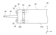
- FIG. 2 is a top view of a bonding arm of the wire bonding apparatus of FIG. 1 .
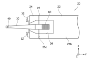
- 2 is a bottom view of a bonding arm of the wire bonding apparatus of FIG. 1 .
- FIG. 2 is a perspective view of the wire clamp device of FIG. 1 .
- 13 is a flow chart illustrating a method for registering a resonant frequency. 13 is a graph showing a Fourier transform of an output current when the tip of an arm part collides.
- 5 is a flowchart showing a part of a calibration method for a wire clamp device according to an embodiment of the present invention.
- 5 is a flowchart showing a part of a calibration method for a wire clamp device according to an embodiment of the present invention.
- 13 is a graph obtained by Fourier transforming an output current immediately before the arm portion starts to open and reaches an open state. 13 is a graph obtained by Fourier transforming an output current immediately after the arm portion starts to open and is in an open state.
- 5 is a flowchart showing a part of a calibration method for a wire clamp device according to an embodiment of the present invention.
- 5 is a flowchart showing a part of a calibration method for a wire clamp device according to an embodiment of the present invention.
- Figure 1 is a diagram showing an overall schematic of the wire bonding apparatus according to this embodiment.
- Figure 2 is a top view of a bonding arm in the wire bonding apparatus of Figure 1.
- Figure 3 is a bottom view of the bonding arm in the wire bonding apparatus of Figure 1.
- Figure 4 is a perspective view of the wire clamp device of Figure 1.
- the wire bonding apparatus 1 includes an XY drive mechanism 10, a Z drive mechanism 12, a bonding arm 20, an ultrasonic horn 30, a bonding tool 40, a load sensor 50, an ultrasonic vibrator 60, a wire clamp device 70, and a wire bonding control unit 90.
- the XY drive mechanism 10 is configured to be slidable in the XY axis direction (directions parallel to the bonding surface), and the XY drive mechanism (linear motor) 10 is provided with a Z drive mechanism (linear motor) 12 that can swing the bonding arm 20 in the Z axis direction (direction perpendicular to the bonding surface).
- the bonding arm 20 is supported by a support shaft 14 and is configured to be freely swingable relative to the XY drive mechanism 10.
- the bonding arm 20 is formed in a substantially rectangular parallelepiped shape extending from the XY drive mechanism 10 to a bonding stage 16 on which a workpiece (e.g., a semiconductor die or substrate) 18 to be bonded is placed.
- the support shaft 14 is, for example, at substantially the same height as the working surface (bonding surface) of the workpiece 18.
- the bonding arm 20 comprises an arm base end 22 attached to the XY drive mechanism 10, an arm tip end 24 located at the tip side of the arm base end 22 and to which an ultrasonic horn 30 is attached, and a flexible connecting portion 23 connecting the arm base end 22 and the arm tip end 24.
- the connecting portion 23 is composed of slits 25a, 25b of a predetermined width extending from the top surface 21a of the bonding arm 20 toward the bottom surface 21b, and a slit 25c of a predetermined width extending from the bottom surface 21b of the bonding arm 20 toward the top surface 21a.
- the connecting portion 23 is configured as a locally thin portion by each of the slits 25a, 25b, 25c, so that the arm tip portion 24 is configured to bend relative to the arm base end portion 22.
- a recess 26 is formed on the bottom surface 21b of the bonding arm 20 to accommodate the ultrasonic horn 30.
- the ultrasonic horn 30 is attached to the arm tip 24 with a horn fixing screw 32 while being accommodated in the recess 26 of the bonding arm 20.
- the ultrasonic horn 30 holds the bonding tool 40 at its tip protruding from the recess 26, and an ultrasonic vibrator 60 that generates ultrasonic vibrations is provided in the recess 26.
- Ultrasonic vibrations are generated by the ultrasonic vibrator 60, which are transmitted to the bonding tool 40 by the ultrasonic horn 30, and ultrasonic vibrations can be applied to the bonding target via the bonding tool 40.
- the ultrasonic vibrator 60 is, for example, a piezoelectric vibrator.
- slits 25a and 25b are formed in order on the top surface 21a side of the bonding arm 20 from the top surface 21a to the bottom surface 21b.
- the upper slit 25a is formed wider than the lower slit 25b.
- a load sensor 50 is provided in the upper slit 25a which is formed wider.
- the load sensor 50 is fixed to the arm tip 24 by a preload screw 52.
- the load sensor 50 is arranged so as to be sandwiched between the arm base end 22 and the arm tip 24.
- the load sensor 50 is offset from the longitudinal central axis of the ultrasonic horn 30 in the direction of approaching and retracting from the bonding target, and is attached between the center of rotation of the bonding arm 20 and the mounting surface of the ultrasonic horn 30 at the arm tip 24 (i.e., the tip surface of the arm tip 24 on the bonding tool 40 side).
- the ultrasonic horn 30 that holds the bonding tool 40 is attached to the arm tip 24.
- the arm tip 24 bends relative to the arm base end 22, making it possible for the load sensor 50 to detect the load.
- the load sensor 50 is, for example, a piezoelectric load sensor.
- the bonding tool 40 is for inserting the wire 42, and is, for example, a capillary with an insertion hole 41.
- the wire 42 used for bonding is inserted into the insertion hole 41 of the bonding tool 40, and a part of the wire 42 can be paid out from the tip.
- a pressing portion for pressing the wire 42 is provided at the tip of the bonding tool 40.
- the pressing portion has a shape that is rotationally symmetrical around the axial direction of the insertion hole 41 of the bonding tool 40, and has a pressing surface on the underside around the insertion hole 41.
- the bonding tool 40 is attached to the ultrasonic horn 30 in a replaceable manner by spring force or the like.
- a wire clamp device 70 is provided above the bonding tool 40 and is configured to restrain or release the wire 42 at a predetermined timing.
- a wire tensioner 46 is provided further above the wire clamp device 70 and is configured to pass the wire 42 through and apply an appropriate tension to the wire 42 during bonding.
- the material of the wire 42 is appropriately selected based on ease of processing and low electrical resistance, and may be, for example, gold (Au), copper (Cu) or silver (Ag).
- the wire 42 is bonded to the first bond point of the workpiece 18 by a free air ball 43 extending from the tip of the bonding tool 40.
- the wire clamp device 70 corresponds to an example of a clamp device that clamps an object to be processed.
- the object to be processed is a wire.
- the wire clamp device 70 includes a pair of arms 72a, 72b and a drive unit 76 attached to the main body of the wire bonding device 1.
- the pair of arms 72a, 72b have tip ends 73a, 73b for clamping the wire 42 and base ends 74a, 74b, and extend from the tip ends 73a, 73b to the base ends 74a, 74b in a direction approximately perpendicular to the wire axis direction.
- Clamp pieces 71a, 71b that come into contact with the wire 42 are provided on the opposing surfaces of the tip ends 73a, 73b.
- the drive unit 76 is also provided with a piezoelectric element 80 that opens and closes the tip ends 73a, 73b of the pair of arms 72a, 72b.
- the opening and closing operation of the pair of arms 72a, 72b of the piezoelectric element 80 is controlled by supplying a drive voltage from a wire bonding control unit 90 (specifically, a supply unit 90a).
- the end of the drive unit 76 opposite the pair of arms 72a, 72b is fixed to the body of the wire bonding device 1. Note that FIG. 1 shows the wire clamp device 70 in the state where the extension direction of the pair of arms 72a, 72b is viewed from the tip end 73a, 73b side.
- the pair of arm portions 72a, 72b are connected to the drive unit 76 at their base ends 74a, 74b via a plurality of connecting portions 77a, 77b, 78a, 78b.
- the pair of connecting portions 78a, 78b are provided on both outer sides of the pair of arm portions 72a, 72b, and the pair of connecting portions 77a, 77b are provided at a position sandwiched between the pair of connecting portions 78a, 78b.
- These connecting portions are configured as elastically deformable constricted portions.
- the pair of connecting portions 77a, 77b are also connected to each other by an action portion 79.
- a piezoelectric element 80 is provided between the drive unit 76 and the action portion 79 with both ends fixed.
- the piezoelectric element 80 expands and contracts in the direction in which the pair of arms 72a and 72b extend, causing each of the connecting parts 77a, 77b, 78a, and 78b to elastically deform so as to open and close the tip parts 73a and 73b of the pair of arms 72a and 72b.
- each of the connecting parts 77a, 77b, 78a, and 78b has spring properties in the direction in which the tip parts 73a and 73b close.
- the piezoelectric element 80 is, for example, a stacked piezoelectric actuator in which multiple layers of piezoelectric elements are stacked in the direction connecting the driving unit 76 and the action unit 79.
- the pair of arms 72a, 72b (clamp pieces 71a, 71b, tip portions 73a, 73b, and base portions 74a, 74b) are made of, for example, a conductive material.
- the amount of movement of the tips 73a, 73b at this time corresponds to the amount of extension of the piezoelectric element 80 expanded according to the ratio of the length from the action part 79 to the connecting part and the length from the connecting part to the tips 73a, 73b.
- the amount of opening and closing of the pair of arms 72a, 72b is the distance between the clamp pieces 71a, 71b in the opening and closing direction
- the amount of movement of the tips 73a, 73b corresponds to the amount of change in the amount of opening and closing of the pair of arms 72a, 72b.
- the wire clamp load by the tips 73a, 73b decreases in proportion to the voltage value applied to the piezoelectric element 80, and when the voltage value reaches a reference voltage value, the clamp pieces 71a, 71b of the tips 73a, 73b are in contact with each other with the wire clamp load being zero.
- the tips 73a, 73b open in the direction away from each other.
- the state in which the tips 73a, 73b are in contact with each other is the "closed state” of the pair of arms 72a, 72b, and the state in which the tips 73a, 73b are separated from each other is the "open state” of the pair of arms 72a, 72b.
- the wire bonding control unit 90 is connected to each of the components, such as the XY drive mechanism 10, the Z drive mechanism 12, the ultrasonic horn 30 (ultrasonic transducer 60), the load sensor 50, and the wire clamp device 70, so that signals can be sent and received between them. By controlling the operation of these components using the wire bonding control unit 90, the necessary processing for wire bonding can be performed.
- the wire bonding control unit 90 is connected to an operation unit 92 for inputting control information and a display unit 94 for outputting control information. This allows an operator to input the necessary control information through the operation unit 92 while viewing the screen on the display unit 94.
- the wire bonding control unit 90 is a computer device equipped with a CPU (Central Processing Unit) and memory, and the memory stores a bonding program for performing the processing required for wire bonding and various data processed by each component in the wire bonding control unit 90, which will be described later.
- the wire bonding control unit 90 is configured to control the operations required to calibrate the wire clamp device, which will be described later. For example, the wire bonding control unit 90 executes each operation for calibration by having the CPU execute a program stored in the memory.
- the wire bonding control unit 90 includes a supply unit 90a, a detection unit 90b, a determination unit 90c, a registration unit 90d, and a calibration unit 90e.
- the supply unit 90a generates a DC or pulsating voltage and supplies it to the piezoelectric element 80. Specifically, the supply unit 90a supplies a DC voltage as the operating voltage to the piezoelectric element 80 in the wire bonding process, and supplies a pulsating current in which a DC component and an AC component are superimposed as the drive voltage to the piezoelectric element 80 in the calibration process of the wire clamp device 70.
- the DC component By supplying a pulsating current to the piezoelectric element 80, the DC component applies a load to the tips 73a, 73b of the pair of arm portions 72a, 72b in the opposite direction (opening direction) to the wire clamp load, and the AC component of the pulsating current vibrates the tips 73a, 73b of the pair of arm portions 72a, 72b in the opening and closing directions.
- the voltage of the DC component of the pulsating current is variable within a range in which the pair of arm portions 72a, 72b can be switched between the open and closed states.
- the frequency of the AC component of the pulsating current is variable within a range that includes the resonant frequency fr that is determined based on the natural angular frequency of the pair of arms 72a, 72b.
- the supply unit 90a increases or decreases the voltage of the DC component stepwise or continuously during one stage of the calibration process.
- the supply unit 90a increases or decreases the frequency of the AC component stepwise or continuously during one stage of the calibration process.
- the detection unit 90b detects the output current from the piezoelectric element 80 when the pair of arms 72a, 72b vibrate in the opening and closing direction as a result of the piezoelectric element 80 being driven by the supply unit 90a.
- the output current is an example of an output signal output from the driven piezoelectric element 80.
- a potential difference is generated in the piezoelectric element 80. This potential difference changes depending on whether the pair of arms 72a, 72b collide with each other. This potential difference also changes depending on whether the pair of arms 72a, 72b are in a resonant state.
- the detection unit 90b detects a change in the output current based on such a change in the potential difference of the piezoelectric element 80.
- the detection unit 90b stores data related to the detected output current in the memory of the wire bonding control unit 90.
- the determination unit 90c acquires data on the output current stored in memory, and determines the open/closed state of the pair of arm portions 72a, 72b based on the occurrence of harmonic components of the resonant frequency fr in the output current.
- harmonic components are detected as the output current in addition to the fundamental component of the resonant frequency fr.
- the harmonic components of the resonant frequency fr contained in the output current become very small or nearly zero when the pair of arm portions 72a, 72b are in the closed state. Using this, the determination unit 90c determines the open/closed state of the pair of arm portions 72a, 72b.
- the supply unit 90a changes the voltage of the DC component of the drive voltage while setting the frequency of the AC component to the resonant frequency fr
- the determination unit 90c determines the open/closed state of the pair of arms 72a, 72b based on the presence or absence and strength of harmonic components in the output current.
- the determination unit 90c performs a Fourier transform on the output current and calculates the intensity of the fundamental component of the resonant frequency fr and the intensity of the harmonic components of the resonant frequency fr.
- the harmonic components of the resonant frequency fr may include multiple higher harmonics including the second harmonic f2 of the resonant frequency fr, and include, for example, the second harmonic f2, the third harmonic f3, and the fourth harmonic f4.
- the determination unit 90c calculates the intensity ratio of the harmonic components to the fundamental component of the resonant frequency fr, and calculates the rate of change of the intensity ratio with respect to the voltage change of the DC component in the drive voltage. Then, when the rate of change of the intensity ratio exceeds a threshold value, the determination unit 90c determines that the pair of arm portions 72a, 72b have switched between the open state and the closed state.
- the determination unit 90c improves the accuracy of the determination by making a determination based on the rate of change of the intensity ratio relative to the voltage change. However, if the determination unit 90c is capable of determining the open/closed state of the pair of arms 72a, 72b, it may also make a determination based on the intensity ratio of the harmonic components to the fundamental wave component, or based on the intensity of the harmonic components.
- the determination unit may determine the resonance state of the pair of arm portions 72a, 72b.
- the determination unit 90c determines the resonance state of the pair of arm portions 72a, 72b based on the occurrence of a component caused by the collision of the pair of arm portions 72a, 72b in the output current detected by the detection unit 90b.
- the output current includes a component caused by the AC component of the drive voltage of the pair of arm portions 72a, 72b, as well as a component caused by the collision of the pair of arm portions 72a, 72b with each other (hereinafter referred to as the "collision component").
- the determination unit 90c determines the resonance state of the pair of arm portions 72a, 72b.
- the frequency of the AC component of the drive voltage is changed while the voltages of the DC and AC components of the drive voltage are set so that the pair of arms 72a, 72b collide with each other when vibrating in a resonant state, but do not collide when vibrating in a non-resonant state.
- the determination unit 90c determines the open/closed state of the pair of arms 72a, 72b based on the presence or absence and strength of a collision component in the output current.
- the judgment unit 90c performs a Fourier transform on the output current to calculate the intensity of the collision component.
- the frequency fx of the collision component is higher than the fundamental wave of the resonance frequency fr, for example, about five times as high as the resonance frequency fr.
- the intensity of the collision component is smaller than the intensity of the fundamental wave component of the resonance frequency fr, and is greater than the intensity of the harmonic component of the resonance frequency fr.
- the judgment unit 90c judges that the pair of arm portions 72a, 72b are vibrating in a resonant state.
- the registration unit 90d registers the DC component voltage of the drive voltage when the pair of arms 72a, 72b switch between the open and closed states as a reference voltage based on the judgment result of the judgment unit 90c on the open and closed states of the pair of arms 72a, 72b.
- the reference voltage when the pair of arms 72a, 72b contact each other in the closed state is a DC voltage equivalent to a state in which they contact each other with a wire clamp load substantially zero (zero load point).
- the reference voltage when the pair of arms 72a, 72b clamp a wire or a calibration jig with higher dimensional accuracy than the wire in the closed state is a DC voltage equivalent to a state in which the pair of arms 72a, 72b clamp a wire or a calibration jig with a substantially zero wire clamp load (zero load point).
- a reference voltage may be, for example, the reference voltage when the pair of arm portions 72a, 72b switch from an open state to a closed state, or the reference voltage when the pair of arm portions 72a, 72b switch from a closed state to an open state.
- the time when the open state switches to the closed state is referred to as "end of closing" and the time when the closed state switches to the open state is referred to as "start of opening.”
- the registration unit 90d registers at least one of the reference voltage at the end of closing and the reference voltage at the beginning of opening when the pair of arms 72a, 72b contact each other in the closed state, and the reference voltage at the end of closing and the reference voltage at the beginning of opening when the pair of arms 72a, 72b clamp a wire or a calibration jig.
- the relationship between the voltage applied to the pair of arms 72a, 72b and the opening amount shows hysteresis.
- the registration unit 90d registers both the reference voltage at the end of closing and the reference voltage at the beginning of opening.
- the registration unit 90d calculates and registers the rate of change of the opening amount of the pair of arms 72a, 72b with respect to the voltage applied to the piezoelectric element 80.
- the data registered by the registration unit 90d is stored in the memory of the wire bonding control unit 90. An example of the calculation of the reference voltage and the rate of change of the opening amount in the registration unit 90d will be described later.
- the calibration unit 90e reads out from the memory the data regarding the reference voltage and the rate of change of the opening and closing amount registered by the registration unit 90d, and calibrates the operating voltage (DC voltage) to be applied to the piezoelectric element 80 in the wire bonding process.
- the calibration unit 90e may correct the value of the operating voltage that has already been set, or may set a new operating voltage to be applied to the piezoelectric element 80.
- the operating voltage calibrated by the calibration unit 90e is stored in the memory of the wire bonding control unit 90.
- the supply unit 90a can read out the calibrated operating voltage stored in the memory in the wire bonding process, and drive the piezoelectric element 80 based on the operating voltage.
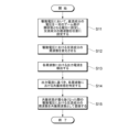
- FIG. 5 is a flowchart showing a method for registering a resonance frequency.
- FIG. 6 is a graph showing a Fourier transform of an output current when the tip of the arm part collides.
- FIGS. 7 and 8 are flowcharts showing a part of a calibration method for the wire clamp device according to the embodiment of the present invention.
- FIGS. 7 and 8 are flowcharts showing a part of a calibration method for the wire clamp device according to the embodiment of the present invention.
- FIGS. 7 and 8 are flowcharts showing a part of a calibration method for the wire clamp device according to the embodiment of the present invention.
- FIGS. 7 and 8 are flowcharts showing a part of a calibration method for the wire clamp device according to the embodiment of the present invention.
- FIGS. 7 and 8 are flowcharts showing a part of a calibration method for the wire clamp device according to the embodiment of the present invention.
- FIGS. 7 and 8 are flowcharts showing a part of a calibration method for the wire clamp device according to the embodiment of the present invention.
- FIGS. 9 and 10 are graphs showing a part of a calibration method for the wire clamp device according to the embodiment of the present invention.
- FIGS. 11 and 12 are flowchart ...
- the graphs shown in FIGS. 6, 9, and 10 are obtained by FFT (Fast Fourier Transform) processing of data obtained by sampling the output current at 100 kSPS using a current detection circuit, with the horizontal axis representing frequency and the vertical axis representing intensity.
- FFT Fast Fourier Transform
- the calibration method according to this embodiment can be performed using the wire bonding apparatus 1.
- the calibration method of the wire clamping apparatus 70 according to this embodiment can be performed when wire bonding is completed (i.e., before the next wire bonding is started), during teaching for wire bonding, etc.
- the resonant frequency fr of the pair of arms 72a, 72b is used. Therefore, if the resonant frequency fr varies due to machine differences or changes over time, it is desirable to register the resonant frequency fr immediately before calibration. For this reason, first, a method for registering the resonant frequency fr of the pair of arms 72a, 72b will be described with reference to FIG. 5. Here, as shown in FIG. 6, it is determined whether the pair of arms 72a, 72b are vibrating at the resonant frequency fr based on the occurrence of collision components at frequency fx. Note that if the resonant frequency fr is known, the process of registering the resonant frequency fr may be omitted.
- the voltage of the DC component of the drive voltage is set to a voltage that causes the pair of arm portions 72a, 72b to be in an open state, and the frequency of the AC component is set arbitrarily (S11).
- the voltage of the AC component of the drive voltage is set to a magnitude that causes the pair of arm portions 72a, 72b to collide with each other when vibrating in a resonant state, but does not collide when vibrating in a non-resonant state.
- the voltage of the DC component is set to 138V
- the voltage of the AC component is set to 10V.
- the supply unit 90a changes the frequency of the AC component within a frequency range that includes the expected resonance frequency fr. For example, the supply unit 90a increases the frequency of the AC component from 1.7 kHz to 2.7 kHz in increments of 0.05 kHz. Then, the output current at each frequency is detected (S13).
- the resonant state at each frequency is determined based on the output current (S14).
- the resonant state is determined based on the strength of the frequency fx of the collision component shown in FIG. 6.
- the frequency fx of the collision component exceeds a threshold value, it is determined that the pair of arm portions 72a, 72b is in a resonant state.
- the frequency of the AC component in the drive voltage when the resonant state is strongest is registered as the resonant frequency fr (S15).
- the frequency of the AC component when the frequency fx of the collision component is strongest is registered as the resonant frequency fr.
- the frequency of that AC component is registered as the resonant frequency fr in step S15.
- the resonant frequency fr is stored in the memory of the wire bonding control unit 90 by the registration unit 90d.
- the resonant frequency fr is, for example, 2.45 kHz.
- FIG. 7 a method for registering a reference voltage at the beginning of opening when the pair of arms 72a, 72b are not clamping anything will be described.
- a drive voltage including an AC component of the resonant frequency fr when a drive voltage including an AC component of the resonant frequency fr is applied, it is determined whether the pair of arms 72a, 72b are in an open or closed state based on the generation state of harmonic components near the second harmonic frequency f2 (f2 ⁇ fr x 2), the third harmonic frequency f3 (f3 ⁇ fr x 3), and the fourth harmonic frequency f4 (f4 ⁇ fr x 4) of the resonant frequency fr.
- the frequency of the AC component in the drive voltage is set to the resonant frequency fr
- the voltage of the DC component is set to a voltage at which the pair of arms 72a, 72b are in a closed state (S21).
- the resonant frequency fr used here is the one registered in step S15.
- the supply unit 90a reads the resonant frequency fr from the memory and sets the frequency of the AC component.
- the supply unit 90a sets the voltage of the DC component to be smaller than the expected reference voltage. For example, the voltage of the DC component is set to 40 V, and the voltage of the AC component is set to 8 V.
- the output current detected by the current detection circuit in detection unit 90b is Fourier transformed to calculate peak intensities near 1x (fundamental), 2x (second harmonic f2), 3x (third harmonic f3), and 4x (fourth harmonic f4) of the resonant frequency fr.
- the intensity of the harmonic components is the sum of the intensities of the second harmonic, third harmonic, and fourth harmonic.
- the intensity of the harmonic components is divided by the intensity of the fundamental component to calculate the intensity ratio.
- the harmonic orders included in the intensity of the harmonic components are not limited to the above. It is not necessary to include the intensities of any of the second through fourth harmonics, and the intensity of the fifth or higher harmonics may be included.
- the intensity of the harmonic components may also be the intensity of a single harmonic order.
- the voltage of the DC component in the drive voltage is increased by one step (S23). If the increase in the DC component voltage is too small, the change in the intensity of the harmonic components will be too small, reducing the accuracy of the reference voltage determination, and if the increase in the DC component voltage is too large, the error in the reference voltage will increase. For this reason, it is desirable that the change in the DC component voltage increased by the supply unit 90a in step S23 be about 1V. However, the increase in the DC component voltage is not limited to the above, and may be about 0.5V or about 1.5V.
- step S24 the intensity ratio of the harmonic components to the fundamental component of the resonant frequency fr is calculated (S24).
- the intensity of the harmonic components is divided by the intensity of the fundamental component to calculate the intensity ratio.
- a threshold value (S25).
- the intensity ratio calculated in step S24 is divided by the intensity ratio calculated in step S22 to calculate the rate of change in the intensity ratio. If this rate of change in the intensity ratio exceeds the threshold value, it is determined that the pair of arm portions 72a, 72b have switched from a closed state to an open state.
- This threshold value is, for example, a value that is set in advance, and is set to an arbitrary value, for example, between 10% and 60%.
- the threshold value for the rate of change of the intensity ratio may be a value determined during calibration.
- the threshold value may be determined based on the average value, maximum value, or median value of the rate of change of the intensity ratio when the voltage of the DC component is increased by any number of steps while the pair of arms 72a, 72b are securely in a closed state.
- the threshold value may be set to a multiple such as two or three times the average value, maximum value, or median value of the rate of change of the intensity ratio.
- step S25 NO If the rate of change in the intensity ratio does not exceed the threshold value (S25 NO), the process returns to step S23, where the voltage of the DC component in the drive voltage is increased by another step, and in step S24, the intensity ratio of the harmonic component to the fundamental component of the resonant frequency fr is calculated. Then, in step S25, the rate of change in the intensity ratio before and after the change in the DC component voltage is calculated to determine whether it exceeds the threshold value.
- the voltage of the DC component is 66V
- the intensity ratio of the harmonic components including the second harmonic f2, the third harmonic f3, and the fourth harmonic f4 to the fundamental component is approximately 3.777%.
- the rate of change in the intensity ratio when the voltage of the DC component is increased from 65V to 66V is approximately -3.038%.
- the voltage of the DC component is 67V
- the intensity ratio of the harmonic components to the fundamental component is approximately 6.138%.
- the rate of change in the intensity ratio when the voltage of the DC component is increased from 66V to 67V is approximately 62.496%.
- the rate of change in the intensity ratio becomes much larger than the previous rate of change.
- the intensity ratio is about 2.935% when the DC component voltage is 40 V, about 3.199% when the DC component voltage is 41 V, and the rate of change in the intensity ratio is about 8.988% when the DC component voltage is increased from 40 V to 41 V.
- the intensity ratio is small and is therefore susceptible to the effects of noise, etc., and the rate of change in the intensity ratio can be either positive or negative, but the rate of change in the intensity ratio when the pair of arms 72a, 72b switch from the closed state to the open state is a large positive value.
- the calibration jig is set between the pair of arms 72a, 72b (S31), and the reference voltage at which the calibration jig begins to open when clamping the calibration jig is registered (S32).
- steps S21 to S26 are executed.
- the reference voltage at the beginning of opening differs between when the pair of arms 72a, 72b clamp nothing and when the calibration jig is clamped. This is because when the calibration jig is clamped, the pair of arms 72a, 72b in the closed state are separated from each other by the dimension of the calibration jig in the opening and closing direction of the pair of arms 72a, 72b.
- the reference voltage at the beginning of opening when the calibration jig is clamped is greater than the reference voltage at the beginning of opening when nothing is clamped.
- the voltage difference of the reference voltage at the beginning of opening is calculated by subtracting the reference voltage at the beginning of opening when nothing is clamped, which was registered in step S26, from the reference voltage at the beginning of opening when the calibration jig is clamped, which was registered in step S32.
- the rate of change of the opening/closing amount of the pair of arms 72a, 72b with respect to the applied voltage when the pair of arms 72a, 72b start to open is calculated (S34).
- the voltage difference calculated in step S33 corresponds to the applied voltage added to the piezoelectric element 80 when the opening/closing amount of the pair of arms 72a, 72b is changed by the dimension of the calibration jig in the opening/closing direction.
- the opening/closing amount of the pair of arms 72a, 72b is the distance between the clamp pieces 71a, 71b in the opening/closing direction.
- the rate of change of the opening/closing amount of the pair of arms 72a, 72b with respect to the applied voltage is calculated by dividing the dimension of the calibration jig in the opening/closing direction by the voltage difference calculated in step S33.
- step S35 the rate of change in the amount of opening and closing of the pair of arm portions 72a, 72b at the beginning of opening is registered (S35).
- the rate of change in the amount of opening and closing calculated in step S34 is stored in the memory of the wire bonding control unit 90.
- Step S41 differs from step S21 in that the voltage of the DC component of the drive voltage is set to a voltage at which the pair of arms 72a, 72b are in an open state rather than a closed state.
- the voltage of the DC component is set to 100 V
- the voltage of the AC component is set to 5 V.
- Step S42 is the same as step S22.
- Step S43 differs from step S23 in that the voltage of the DC component is lowered instead of increased.
- the amount of change in the voltage of the DC component in step S43 is the same as in step S23, and is, for example, about 1 V.
- Step S44 is the same as step S24.
- Step S45 it is determined whether the rate of change of the intensity ratio exceeds a threshold value (S45), and based on the result of this determination, the voltage of the DC component before it is lowered is registered as the reference voltage at the end of closing (S46).
- Step S45 differs from step S25 in that a different threshold value is set, and the threshold value in step S45 is set to zero, for example.
- the intensity of the harmonic components decreases as the pair of arms 72a, 72b approaches the closed state from the open state, so the rate of change in the intensity ratio due to the voltage drop is a negative value.
- the balance between the input and the reaction changes due to the change in the open/closed state of the pair of arms 72a, 72b, so the rate of change in the intensity ratio is a positive value.
- the rate of change in the intensity ratio randomly repeats positive and negative values.
- the intensity ratio is about 6.383%, and when the voltage of the DC component is dropped from 58V to 57V, the rate of change in the intensity ratio is about -13.314%.
- the intensity ratio is about 5.303%, and when the voltage of the DC component is dropped from 57V to 56V, the rate of change in the intensity ratio is about -16.933%.
- the intensity ratio is about 3.540%, and when the DC component voltage is lowered from 53V to 52V, the rate of change in the intensity ratio is about -22.834%.
- the intensity ratio is about 3.591%, and when the DC component voltage is lowered from 52V to 51V, the rate of change in the intensity ratio is about 1.420%.
- the pair of arms 72a, 72b have finished closing, and the intensity ratio will not decrease any further, so even when the DC component voltage is lowered from 52V to 51V, the intensity ratio did not decrease. Therefore, 52V, which is the voltage before the drop when the rate of change in the intensity ratio becomes a positive value, is registered as the reference voltage at the end of closing.
- the threshold value of the rate of change of the intensity ratio at the end of closing is not limited to zero.
- the threshold value may be set to any value between -10% and 1%.
- the open/closed state may be determined based on whether the absolute value of the rate of change of the intensity ratio is below the threshold value.
- the absolute value of the rate of change of the intensity ratio when the absolute value of the rate of change of the intensity ratio is greater than the threshold value, it may be determined that the pair of arms 72a, 72b are in the open state, and when the absolute value of the rate of change of the intensity ratio is smaller than the threshold value, it may be determined that the pair of arms 72a, 72b are in the closed state. This is because when the pair of arms 72a, 72b approach the closed state in the open state, the rate of change of the intensity ratio is large, but when the pair of arms 72a, 72b are in the closed state, the intensity ratio does not change substantially, that is, the rate of change of the intensity ratio becomes small.
- the calibration jig is set between the pair of arms 72a, 72b (S51), and the reference voltage at the end of closing when clamping the calibration jig is registered (S52).
- steps S41 to S46 are executed.
- the voltage difference of the reference voltage at the end of closing due to the presence or absence of the calibration jig is calculated (S53).
- the voltage difference of the reference voltage at the end of closing is calculated by subtracting the reference voltage at the end of closing when nothing is clamped, which was registered in step S46, from the reference voltage at the end of closing when the calibration jig is clamped, which was registered in step S52.
- Step S54 is the same as step S34.
- Step S55 is the same as step S35.
- the operating voltage is calibrated (S36).
- the operating voltage is calibrated based on the registered reference voltage at the start of opening of the pair of arm portions 72a, 72b, the rate of change of the opening amount at the start of opening, and the reference voltage at the end of closing, and the rate of change of the opening amount at the end of closing.
- This calibration method is preferably performed each time the wire bonding process is performed in a different manner, for example, when wire bonding is performed with different wire diameters or in different temperature environments. This is particularly effective because it allows calibration according to the ease of opening the wire clamp device 70 that corresponds to each situation.
- the wire 42 to be wire-bonded after calibration may be used instead of the calibration jig.
- the open/closed state of the pair of arms 72a, 72b is determined based on the occurrence of harmonic components in the output signal, so that the influence of machine differences such as the ease of vibration, the ease of vibration transmission, and the ease of detecting the output signal can be reduced when determining the open/closed state.
- the clamp device described in [Appendix 1] further includes a registration unit 90d that registers the DC component voltage when the pair of arm portions 72a, 72b switch between an open state and a closed state as a reference voltage, and a calibration unit 90e that calibrates the operating voltage applied to the piezoelectric element 80 based on the reference voltage.
- the output current from the pair of arm portions 72a, 72b can be expressed using the time derivative of the output voltage, so even if a change in magnitude is difficult to detect as an output voltage, it may be a change in magnitude that can be detected as an output current. Therefore, the detection accuracy of the detection portion 90b can be improved, and the calibration accuracy can be improved.
- the components contained in the output signal can be separated based on frequency and the intensity of each component can be compared.
- the open/closed state can be determined based on an intensity ratio that is easier to compare than harmonic components that are easily affected by noise, improving the accuracy of the determination.
- the open/closed state can be determined based on the rate of change of the intensity ratio, which is easier to compare than the intensity ratio, which is more susceptible to the effects of noise, thereby improving the accuracy of the determination.
- the registration unit 90d when the pair of arm portions 72a, 72b are in contact with each other in the closed state, registers the DC component of the voltage when the pair of arm portions 72a, 72b switch from a closed state to an open state as a reference voltage when the pair of arm portions 72a, 72b start to open, and registers the DC component of the voltage when the pair of arm portions 72a, 72b switch from an open state to a closed state as a reference voltage when the pair of arm portions 72a, 72b finish closing.
- the registration unit 90d when the pair of arm portions 72a, 72b clamp a calibration jig having higher dimensional accuracy than the wire 42 in a closed state, registers the DC component of the voltage when the pair of arm portions 72a, 72b switch from a closed state to an open state as a reference voltage when the pair of arm portions 72a, 72b start to open, and registers the DC component of the voltage when the pair of arm portions 72a, 72b switch from an open state to a closed state as a reference voltage when the pair of arm portions 72a, 72b finish closing.
- This clamp device 70 is described in any one of [Appendix 2] to [Appendix 7].
- the registration unit 90d when the pair of arm portions 72a, 72b clamp the wire 42 in a closed state, registers the DC component voltage when the pair of arm portions 72a, 72b switch from a closed state to an open state as a reference voltage when the pair of arm portions 72a, 72b start to open, and registers the DC component voltage when the pair of arm portions 72a, 72b switch from an open state to a closed state as a reference voltage when the pair of arm portions 72a, 72b finish closing.
- the registration unit 90d registers, as a first reference voltage, a voltage of a DC component when the pair of arm portions 72a, 72b switch between an open state and a closed state in the case where the pair of arm portions 72a, 72b contact each other in the closed state, and registers, as a second reference voltage, a voltage of a DC component when the pair of arm portions 72a, 72b switch between an open state and a closed state in the case where the pair of arm portions 72a, 72b clamp a calibration jig or the wire 42 having higher dimensional accuracy than the wire 42 in the closed state.
- a calibration unit 90 e calibrates the operating voltage applied to the piezoelectric element 80 based on the rate of change of the amount of opening and closing.
- the opening and closing amount of the pair of arms 72a, 72b can also be calibrated in response to the operating voltage, thereby further improving the accuracy and stabilization of the opening and closing operation.
- the accuracy of determining the open/closed state of the pair of arm portions 72a, 72b based on the harmonic components is improved, which improves the accuracy of the calibration and allows for further improvement and stabilization of the opening and closing operation.
- the supply unit 90a increases or decreases the frequency of the AC component while setting the voltage of the DC component to a voltage at which the pair of arm portions 72a, 72b are in an open state
- the determination unit 90c determines the resonant state of the pair of arm portions 72a, 72b based on the occurrence state of components in the output signal due to collision between the pair of arm portions 72a, 72b
- the registration unit 90d registers the frequency of the AC component when the resonant state of the pair of arm portions 72a, 72b is strongest as the resonant frequency of the pair of arm portions 72a, 72b.
- the resonant frequency of the pair of arm portions 72a, 72b can be found before calibration is performed, improving the accuracy of the calibration and further improving the accuracy and stabilization of the opening and closing operation.
- a control method for a wire clamping device 70 including a pair of arm portions 72a, 72b that clamp a wire 42, a drive unit 76 having a piezoelectric element 80 that opens and closes the pair of arm portions 72a, 72b, and a supply unit 90a configured to generate a drive voltage in which a frequency-variable AC component and a voltage-variable DC component are superimposed and to be able to supply the drive voltage to the piezoelectric element 80, the control method including: increasing or decreasing the voltage of the DC component while setting the frequency of the AC component to a resonant frequency of the pair of arm portions 72a, 72b; detecting an output signal output from the driven piezoelectric element 80; and determining the open/closed state of the pair of arm portions 72a, 72b based on the generation status of harmonic components of the resonant frequency in the output signal.
- the open/closed state of the pair of arms 72a, 72b is determined based on the occurrence of harmonic components in the output signal, so that the influence of machine differences such as the ease of vibration, the ease of vibration transmission, and the ease of detecting the output signal can be reduced in determining the open/closed state.
- a control program for operating a wire clamping device 70 including a pair of arm portions 72a, 72b for clamping a wire 42, a drive unit 76 having a piezoelectric element 80 for opening and closing the pair of arm portions 72a, 72b, and a supply unit 90a configured to generate a drive voltage in which a frequency-variable AC component and a voltage-variable DC component are superimposed and supply the drive voltage to the piezoelectric element 80.
- the control program causes a computer to execute the following operations: increase or decrease the voltage of the DC component while setting the frequency of the AC component to the resonance frequency of the pair of arm portions 72a, 72b; detect an output signal output from the driven piezoelectric element 80; and determine the open/closed state of the pair of arm portions 72a, 72b based on the generation status of harmonic components of the resonance frequency in the output signal.
- the open/closed state of the pair of arms 72a, 72b is determined based on the occurrence of harmonic components in the output signal, so that the influence of machine differences such as the ease of vibration, the ease of vibration transmission, and the ease of detecting the output signal can be reduced in determining the open/closed state.
- one aspect of the present invention can improve the accuracy of determining whether a pair of arms are open or closed.
Landscapes
- Engineering & Computer Science (AREA)
- Mechanical Engineering (AREA)
- Manufacturing & Machinery (AREA)
- Wire Bonding (AREA)
- Manipulator (AREA)
- Electrical Discharge Machining, Electrochemical Machining, And Combined Machining (AREA)
Abstract
Description
まず、図1乃至図4を参照しつつ、本願発明の一実施形態に係るワイヤボンディング装置1の構成について説明する。図1は、本実施形態に係るワイヤボンディング装置の全体概略を示した図である。図2は、図1のワイヤボンディング装置のうちボンディングアームの頂面図である。図3は、図1のワイヤボンディング装置のうちボンディングアームの底面図である。図4は図1のワイヤクランプ装置の斜視図である。
次に、図5~図12を参照しつつ、本実施形態に係るワイヤクランプ装置70を用いたキャリブレーション方法について説明する。図5は、共振周波数を登録する方法を示すフローチャートである。図6は、アーム部の先端部が衝突したときの出力電流をフーリエ変換したグラフである。図7,8は、本発明の実施形態に係るワイヤクランプ装置のキャリブレーション方法の一部を示すフローチャートである。図7,8は、一対のアーム部72a,72bの開き始めにおける、基準電圧及び開閉量の変化率を登録する方法を示すフローチャートである。図9は、アーム部が開き始めにおいて開状態となる直前の出力電流をフーリエ変換したグラフである。図10は、アーム部が開き始めにおいて開状態となった直後の出力電流をフーリエ変換したグラフである。図11,12は、本発明の実施形態に係るワイヤクランプ装置のキャリブレーション方法の一部を示すフローチャートである。図11,12は、一対のアーム部72a,72bの閉じ終わりにおける、基準電圧及び開閉量の変化率を登録する方法を示すフローチャートである。なお、図6、図9及び図10に示すグラフは、出力電流を電流検出回路によって100kSPSでサンプリングして得たデータを、FFT(Fast Fourier Transform)処理したものであり、横軸は周波数、縦軸は強度を示している。
ワイヤ42をクランプする一対のアーム部72a,72bと、一対のアーム部72a,72bを開閉させるピエゾ素子80を有する駆動部76と、周波数可変の交流成分及び電圧可変の直流成分が重畳された駆動電圧を生成し、駆動電圧をピエゾ素子80に供給可能に構成された供給部90aであって、交流成分の周波数を一対のアーム部72a,72bの共振周波数に設定した状態で直流成分の電圧を上昇又は降下させる供給部90aと、駆動されたピエゾ素子80から出力される出力信号を検出する検出部90bと、出力信号における共振周波数の高調波成分の発生状況に基づいて、一対のアーム部72a,72bの開閉状態を判定する判定部90cとを備える、クランプ装置70。
一対のアーム部72a,72bにおける開状態と閉状態とが切り替わる際の直流成分の電圧を基準電圧として登録する登録部90dと、基準電圧に基づいて、ピエゾ素子80に印加する使用電圧をキャリブレーションするキャリブレーション部90eとをさらに備える、[付記1]に記載のクランプ装置。
検出部90bは、出力信号として、ピエゾ素子80から出力される出力電流を検出する、[付記2]に記載のクランプ装置70。
判定部90cは、出力電流をフーリエ変換することによって、出力信号における共振周波数の高調波成分の強度を算出する、[付記3]に記載のクランプ装置70。
判定部90cは、出力信号における共振周波数の基本波成分に対する高調波成分の強度比を算出する、[付記4]に記載のクランプ装置70。
判定部90cは、直流成分の電圧変化に対する強度比の変化率を算出する、[付記5]に記載のクランプ装置70。
登録部90dは、直流成分の電圧を第1の電圧から第2の電圧へと変化させたときの強度比の変化率が閾値を上回ったときに、第1の電圧を基準電圧として登録する、[付記6]に記載のクランプ装置70。
登録部90dは、閉状態において一対のアーム部72a,72bが互いに接触する場合において、一対のアーム部72a,72bが閉状態から開状態へと切り替わる際の直流成分の電圧を、一対のアーム部72a,72bの開き始めの基準電圧として登録し、一対のアーム部72a,72bが開状態から閉状態へと切り替わる際の直流成分の電圧を、一対のアーム部72a,72bの閉じ終わりの基準電圧として登録する、[付記2]から[付記7]のいずれか1つに記載のクランプ装置70。
登録部90dは、閉状態において一対のアーム部72a,72bがワイヤ42よりも寸法精度が高い校正治具をクランプする場合において、一対のアーム部72a,72bが閉状態から開状態へと切り替わる際の直流成分の電圧を、一対のアーム部72a,72bの開き始めの基準電圧として登録し、一対のアーム部72a,72bが開状態から閉状態へと切り替わる際の直流成分の電圧を、一対のアーム部72a,72bの閉じ終わりの基準電圧として登録する、[付記2]から[付記7]のいずれか1つに記載のクランプ装置70。
登録部90dは、閉状態において一対のアーム部72a,72bがワイヤ42をクランプする場合において、一対のアーム部72a,72bが閉状態から開状態へと切り替わる際の直流成分の電圧を、一対のアーム部72a,72bの開き始めの基準電圧として登録し、一対のアーム部72a,72bが開状態から閉状態へと切り替わる際の直流成分の電圧を、一対のアーム部72a,72bの閉じ終わりの基準電圧として登録する、[付記2]から[付記7]のいずれか1つに記載のクランプ装置70。
登録部90dは、閉状態において一対のアーム部72a,72bが互いに接触する場合において、一対のアーム部72a,72bにおける開状態と閉状態とが切り替わる際の直流成分の電圧を第1基準電圧として登録し、閉状態において一対のアーム部72a,72bがワイヤ42よりも寸法精度が高い校正治具又はワイヤ42をクランプする場合において、一対のアーム部72a,72bにおける開状態と閉状態とが切り替わる際の直流成分の電圧を第2基準電圧として登録し、第1基準電圧と第2基準電圧との電圧差分、及び、一対のアーム部72a,72bの開閉方向における校正治具又はワイヤ42の寸法に基づき、ピエゾ素子80に印加する電圧に対する一対のアーム部72a,72bの開閉量の変化率を算出して登録し、キャリブレーション部90eは、開閉量の変化率に基づいて、ピエゾ素子80に印加する使用電圧をキャリブレーションする、[付記2]から[付記7]のいずれか1つに記載のクランプ装置70。
共振周波数の高調波成分は、複数の高調波の成分を含む、[付記1]から[付記11]のいずれか1つに記載のクランプ装置70。
供給部90aは、直流成分の電圧を一対のアーム部72a,72bが開状態となる電圧に設定した状態で交流成分の周波数を上昇又は降下させ、判定部90cは、出力信号における一対のアーム部72a,72bの衝突に起因した成分の発生状況に基づいて、一対のアーム部72a,72bの共振状態を判定し、登録部90dは、一対のアーム部72a,72bの共振状態が最も強くなった際の交流成分の周波数を、一対のアーム部72a,72bの共振周波数として登録する、[付記1]から[付記12]のいずれか1つに記載のクランプ装置70。
ワイヤ42をクランプする一対のアーム部72a,72bと、一対のアーム部72a,72bを開閉させるピエゾ素子80を有する駆動部76と、周波数可変の交流成分及び電圧可変の直流成分が重畳された駆動電圧を生成し、駆動電圧をピエゾ素子80に供給可能に構成された供給部90aとを備えるワイヤクランプ装置70の制御方法であって、交流成分の周波数を一対のアーム部72a,72bの共振周波数に設定した状態で直流成分の電圧を上昇又は降下させることと、駆動されたピエゾ素子80から出力される出力信号を検出することと、出力信号における共振周波数の高調波成分の発生状況に基づいて、一対のアーム部72a,72bの開閉状態を判定することとを含む、制御方法。
ワイヤ42をクランプする一対のアーム部72a,72bと、一対のアーム部72a,72bを開閉させるピエゾ素子80を有する駆動部76と、周波数可変の交流成分及び電圧可変の直流成分が重畳された駆動電圧を生成し、駆動電圧をピエゾ素子80に供給可能に構成された供給部90aとを備えるワイヤクランプ装置70を動作させる制御プログラムであって、コンピュータに、交流成分の周波数を一対のアーム部72a,72bの共振周波数に設定した状態で直流成分の電圧を上昇又は降下させることと、駆動されたピエゾ素子80から出力される出力信号を検出させることと、出力信号における共振周波数の高調波成分の発生状況に基づいて、一対のアーム部72a,72bの開閉状態を判定させることとを実行させる、制御プログラム。
70…ワイヤクランプ装置
72a,72b…アーム部
73a,73b…先端部
74a,74b…基端部
76…駆動部
90…ワイヤボンディング制御部
90a…供給部
90b…検出部
90c…判定部
90d…登録部
90e…キャリブレーション部
Claims (15)
- 被処理物をクランプする一対のアーム部と、
前記一対のアーム部を開閉させるピエゾ素子を有する駆動部と、
周波数可変の交流成分及び電圧可変の直流成分が重畳された駆動電圧を生成し、前記駆動電圧を前記ピエゾ素子に供給可能に構成された供給部であって、前記交流成分の周波数を前記一対のアーム部の共振周波数に設定した状態で前記直流成分の電圧を上昇又は降下させる供給部と、
駆動された前記ピエゾ素子から出力される出力信号を検出する検出部と、
前記出力信号における前記共振周波数の高調波成分の発生状況に基づいて、前記一対のアーム部の開閉状態を判定する判定部と
を備える、クランプ装置。 - 前記一対のアーム部における開状態と閉状態とが切り替わる際の前記直流成分の電圧を基準電圧として登録する登録部と、
前記基準電圧に基づいて、前記ピエゾ素子に印加する使用電圧をキャリブレーションするキャリブレーション部と
をさらに備える、
請求項1に記載のクランプ装置。 - 前記検出部は、前記出力信号として、前記ピエゾ素子から出力される出力電流を検出する、
請求項2に記載のクランプ装置。 - 前記判定部は、前記出力電流をフーリエ変換することによって、前記出力信号における前記共振周波数の高調波成分の強度を算出する、
請求項3に記載のクランプ装置。 - 前記判定部は、前記出力信号における前記共振周波数の基本波成分に対する高調波成分の強度比を算出する、
請求項4に記載のクランプ装置。 - 前記判定部は、前記直流成分の電圧変化に対する前記強度比の変化率を算出する、
請求項5に記載のクランプ装置。 - 前記登録部は、前記直流成分の電圧を第1の電圧から第2の電圧へと変化させたときの前記強度比の変化率が閾値を上回ったときに、前記第1の電圧を基準電圧として登録する、
請求項6に記載のクランプ装置。 - 前記登録部は、
閉状態において前記一対のアーム部が互いに接触する場合において、
前記一対のアーム部が閉状態から開状態へと切り替わる際の前記直流成分の電圧を、前記一対のアーム部の開き始めの基準電圧として登録し、
前記一対のアーム部が開状態から閉状態へと切り替わる際の前記直流成分の電圧を、前記一対のアーム部の閉じ終わりの基準電圧として登録する、
請求項2に記載のクランプ装置。 - 前記登録部は、
閉状態において前記一対のアーム部が前記被処理物よりも寸法精度が高い校正治具をクランプする場合において、
前記一対のアーム部が閉状態から開状態へと切り替わる際の前記直流成分の電圧を、前記一対のアーム部の開き始めの基準電圧として登録し、
前記一対のアーム部が開状態から閉状態へと切り替わる際の前記直流成分の電圧を、前記一対のアーム部の閉じ終わりの基準電圧として登録する、
請求項2に記載のクランプ装置。 - 前記登録部は、
閉状態において前記一対のアーム部が前記被処理物をクランプする場合において、
前記一対のアーム部が閉状態から開状態へと切り替わる際の前記直流成分の電圧を、前記一対のアーム部の開き始めの基準電圧として登録し、
前記一対のアーム部が開状態から閉状態へと切り替わる際の前記直流成分の電圧を、前記一対のアーム部の閉じ終わりの基準電圧として登録する、
請求項2に記載のクランプ装置。 - 前記登録部は、
閉状態において前記一対のアーム部が互いに接触する場合において、前記一対のアーム部における開状態と閉状態とが切り替わる際の前記直流成分の電圧を第1基準電圧として登録し、
閉状態において前記一対のアーム部が前記被処理物よりも寸法精度が高い校正治具又は前記被処理物をクランプする場合において、前記一対のアーム部における開状態と閉状態とが切り替わる際の前記直流成分の電圧を第2基準電圧として登録し、
前記第1基準電圧と前記第2基準電圧との電圧差分、及び、前記一対のアーム部の開閉方向における前記校正治具又は前記被処理物の寸法に基づき、前記ピエゾ素子に印加する電圧に対する前記一対のアーム部の開閉量の変化率を算出して登録し、
前記キャリブレーション部は、前記開閉量の変化率に基づいて、前記ピエゾ素子に印加する使用電圧をキャリブレーションする、
請求項2に記載のクランプ装置。 - 前記共振周波数の高調波成分は、複数の高調波の成分を含む、
請求項1に記載のクランプ装置。 - 前記供給部は、前記直流成分の電圧を前記一対のアーム部が開状態となる電圧に設定した状態で前記交流成分の周波数を上昇又は降下させ、
前記判定部は、前記出力信号における前記一対のアーム部の衝突に起因した成分の発生状況に基づいて、前記一対のアーム部の共振状態を判定し、
前記登録部は、前記一対のアーム部の共振状態が最も強くなった際の前記交流成分の周波数を、前記一対のアーム部の共振周波数として登録する、
請求項2に記載のクランプ装置。 - 被処理物をクランプする一対のアーム部と、
前記一対のアーム部を開閉させるピエゾ素子を有する駆動部と、
周波数可変の交流成分及び電圧可変の直流成分が重畳された駆動電圧を生成し、前記駆動電圧を前記ピエゾ素子に供給可能に構成された供給部と
を備えるクランプ装置の制御方法であって、
前記交流成分の周波数を前記一対のアーム部の共振周波数に設定した状態で前記直流成分の電圧を上昇又は降下させることと、
駆動された前記ピエゾ素子から出力される出力信号を検出することと、
前記出力信号における前記共振周波数の高調波成分の発生状況に基づいて、前記一対のアーム部の開閉状態を判定することと
を含む、制御方法。 - 被処理物をクランプする一対のアーム部と、
前記一対のアーム部を開閉させるピエゾ素子を有する駆動部と、
周波数可変の交流成分及び電圧可変の直流成分が重畳された駆動電圧を生成し、前記駆動電圧を前記ピエゾ素子に供給可能に構成された供給部と
を備えるクランプ装置を動作させる制御プログラムであって、
コンピュータに、
前記交流成分の周波数を前記一対のアーム部の共振周波数に設定した状態で前記直流成分の電圧を上昇又は降下させることと、
駆動された前記ピエゾ素子から出力される出力信号を検出させることと、
前記出力信号における前記共振周波数の高調波成分の発生状況に基づいて、前記一対のアーム部の開閉状態を判定させることと
を実行させる、制御プログラム。
Priority Applications (2)
| Application Number | Priority Date | Filing Date | Title |
|---|---|---|---|
| KR1020257007598A KR20250048320A (ko) | 2022-11-08 | 2023-08-30 | 클램프 장치 및 그 제어 방법 및 제어 프로그램 |
| CN202380064175.6A CN119836682A (zh) | 2022-11-08 | 2023-08-30 | 夹紧装置以及其控制方法及控制程序 |
Applications Claiming Priority (2)
| Application Number | Priority Date | Filing Date | Title |
|---|---|---|---|
| JP2022-178998 | 2022-11-08 | ||
| JP2022178998A JP7510203B2 (ja) | 2022-11-08 | 2022-11-08 | クランプ装置並びにその制御方法及び制御プログラム |
Publications (1)
| Publication Number | Publication Date |
|---|---|
| WO2024100970A1 true WO2024100970A1 (ja) | 2024-05-16 |
Family
ID=91032195
Family Applications (1)
| Application Number | Title | Priority Date | Filing Date |
|---|---|---|---|
| PCT/JP2023/031523 Ceased WO2024100970A1 (ja) | 2022-11-08 | 2023-08-30 | クランプ装置並びにその制御方法及び制御プログラム |
Country Status (5)
| Country | Link |
|---|---|
| JP (1) | JP7510203B2 (ja) |
| KR (1) | KR20250048320A (ja) |
| CN (1) | CN119836682A (ja) |
| TW (1) | TWI870887B (ja) |
| WO (1) | WO2024100970A1 (ja) |
Citations (2)
| Publication number | Priority date | Publication date | Assignee | Title |
|---|---|---|---|---|
| WO2018038135A1 (ja) * | 2016-08-23 | 2018-03-01 | 株式会社新川 | ワイヤクランプ装置のキャリブレーション方法及びワイヤボンディング装置 |
| WO2021029174A1 (ja) * | 2019-08-13 | 2021-02-18 | 株式会社新川 | ワイヤボンディング装置 |
Family Cites Families (4)
| Publication number | Priority date | Publication date | Assignee | Title |
|---|---|---|---|---|
| US5314175A (en) * | 1990-02-27 | 1994-05-24 | Matsushita Electric Industrial Co., Ltd. | Wire clamping device and wire clamping method |
| TW521358B (en) * | 2000-09-22 | 2003-02-21 | Asm Tech Singapore Pte Ltd | A method of bonding wires |
| CH698828B1 (de) * | 2007-06-11 | 2009-11-13 | Esec Ag | Drahtklammer für einen Wire Bonder. |
| JP4314313B1 (ja) * | 2008-06-30 | 2009-08-12 | 株式会社新川 | ボンディング装置 |
-
2022
- 2022-11-08 JP JP2022178998A patent/JP7510203B2/ja active Active
-
2023
- 2023-06-07 TW TW112121143A patent/TWI870887B/zh active
- 2023-08-30 KR KR1020257007598A patent/KR20250048320A/ko active Pending
- 2023-08-30 CN CN202380064175.6A patent/CN119836682A/zh active Pending
- 2023-08-30 WO PCT/JP2023/031523 patent/WO2024100970A1/ja not_active Ceased
Patent Citations (2)
| Publication number | Priority date | Publication date | Assignee | Title |
|---|---|---|---|---|
| WO2018038135A1 (ja) * | 2016-08-23 | 2018-03-01 | 株式会社新川 | ワイヤクランプ装置のキャリブレーション方法及びワイヤボンディング装置 |
| WO2021029174A1 (ja) * | 2019-08-13 | 2021-02-18 | 株式会社新川 | ワイヤボンディング装置 |
Also Published As
| Publication number | Publication date |
|---|---|
| JP7510203B2 (ja) | 2024-07-03 |
| JP2024068494A (ja) | 2024-05-20 |
| TW202420492A (zh) | 2024-05-16 |
| TWI870887B (zh) | 2025-01-21 |
| CN119836682A (zh) | 2025-04-15 |
| KR20250048320A (ko) | 2025-04-08 |
Similar Documents
| Publication | Publication Date | Title |
|---|---|---|
| JP6654304B2 (ja) | ワイヤクランプ装置のキャリブレーション方法及びワイヤボンディング装置 | |
| US9899348B2 (en) | Wire bonding apparatus and method of manufacturing semiconductor device | |
| KR102147689B1 (ko) | 와이어 클램프 장치의 캘리브레이션 방법 및 와이어 본딩 장치 | |
| KR101031378B1 (ko) | 진동형 센서 | |
| JP7416491B2 (ja) | ワイヤボンディング装置、ワイヤ切断方法及びプログラム | |
| JP7510203B2 (ja) | クランプ装置並びにその制御方法及び制御プログラム | |
| US20080302857A1 (en) | Wire clamp for a wire bonder | |
| JP7191421B2 (ja) | ワイヤボンディング装置 | |
| CN114434477B (zh) | 手爪的驱动方法及手爪 | |
| TWI859868B (zh) | 打線接合裝置及所述裝置的校準方法 |
Legal Events
| Date | Code | Title | Description |
|---|---|---|---|
| 121 | Ep: the epo has been informed by wipo that ep was designated in this application |
Ref document number: 23888325 Country of ref document: EP Kind code of ref document: A1 |
|
| WWE | Wipo information: entry into national phase |
Ref document number: 202380064175.6 Country of ref document: CN |
|
| ENP | Entry into the national phase |
Ref document number: 20257007598 Country of ref document: KR Kind code of ref document: A |
|
| WWE | Wipo information: entry into national phase |
Ref document number: 1020257007598 Country of ref document: KR |
|
| WWP | Wipo information: published in national office |
Ref document number: 1020257007598 Country of ref document: KR |
|
| WWP | Wipo information: published in national office |
Ref document number: 202380064175.6 Country of ref document: CN |
|
| WWE | Wipo information: entry into national phase |
Ref document number: 11202501814V Country of ref document: SG |
|
| WWP | Wipo information: published in national office |
Ref document number: 11202501814V Country of ref document: SG |
|
| NENP | Non-entry into the national phase |
Ref country code: DE |
|
| 122 | Ep: pct application non-entry in european phase |
Ref document number: 23888325 Country of ref document: EP Kind code of ref document: A1 |