WO2024100879A1 - 通信品質予測装置、通信品質予測方法、およびプログラム - Google Patents
通信品質予測装置、通信品質予測方法、およびプログラム Download PDFInfo
- Publication number
- WO2024100879A1 WO2024100879A1 PCT/JP2022/042052 JP2022042052W WO2024100879A1 WO 2024100879 A1 WO2024100879 A1 WO 2024100879A1 JP 2022042052 W JP2022042052 W JP 2022042052W WO 2024100879 A1 WO2024100879 A1 WO 2024100879A1
- Authority
- WO
- WIPO (PCT)
- Prior art keywords
- communication quality
- point cloud
- cloud data
- quality prediction
- prediction device
- Prior art date
- Legal status (The legal status is an assumption and is not a legal conclusion. Google has not performed a legal analysis and makes no representation as to the accuracy of the status listed.)
- Ceased
Links
Images


Classifications
-
- H—ELECTRICITY
- H04—ELECTRIC COMMUNICATION TECHNIQUE
- H04W—WIRELESS COMMUNICATION NETWORKS
- H04W16/00—Network planning, e.g. coverage or traffic planning tools; Network deployment, e.g. resource partitioning or cells structures
- H04W16/18—Network planning tools
Definitions
- This disclosure relates to a communication quality prediction device, a communication quality prediction method, and a program.
- the Internet of Things in which various devices are connected to the Internet, is becoming a reality, and various devices such as automobiles, drones, and construction machinery vehicles are being connected wirelessly.
- IoT Internet of Things
- M2M Machine to Machine
- Next-generation mobile communications (5G, 6G) are expected to realize high-speed, large-capacity communications using frequencies above 30 GHz, known as millimeter waves.
- communications using high frequencies above the sub-6 GHz band are strongly affected by the surrounding environment.
- millimeter wave and terahertz wave communications the communication quality drops sharply due to obstructions such as human bodies.
- changes in the propagation environment due to the movement of reflecting objects and the Doppler shift caused by the movement of reflecting objects are also known to affect communications. Such abrupt changes in communication quality are a factor that significantly reduces the perceived communication quality.
- Non-patent document 1 a document on existing technology, proposes a device that predicts communication quality when the wireless communication path of millimeter wave communication is blocked by the passage of an object, using physical space information obtained from a depth camera, and controls handover and transmission power. In this way, it has been shown that physical space information is effective in predicting communication quality.
- LiDAR Light Detection And Ranging
- LiDAR can obtain detailed information about the surrounding three-dimensional space.
- the point cloud data obtained by LiDAR is huge in volume, making it difficult to handle in terms of data storage and processing.
- the technology for machine learning models (deep learning models) that target point cloud data is not yet as mature as the technology for handling two-dimensional image data.
- This disclosure has been made in consideration of the above, and aims to reduce the computational costs in predicting communication quality using physical space information.
- a communication quality prediction device is a communication quality prediction device that predicts communication quality, and includes an acquisition unit that acquires point cloud data of a wireless communication area in a time series, a preprocessing unit that converts the point cloud data into a two-dimensional image, and a prediction unit that predicts and calculates the communication quality of a wireless terminal in the wireless communication area from the two-dimensional image in a time series.
- a communication quality prediction method is a communication quality prediction method using a communication quality prediction device that predicts communication quality, which acquires point cloud data of a wireless communication area in a time series, converts the point cloud data into a two-dimensional image, and predicts and calculates the communication quality of a wireless terminal in the wireless communication area from the time-series two-dimensional image.
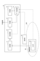
- FIG. 1 is a diagram showing an example of the configuration of a communication quality prediction device according to the present embodiment.
- FIG. 2 is a diagram illustrating an example of point cloud data.
- FIG. 3 is a diagram showing an example of a bird's-eye view.
- FIG. 4 is a flowchart illustrating an example of a process for learning a prediction model.
- FIG. 5 is a flowchart illustrating an example of a process for predicting communication quality.
- FIG. 6 is a diagram showing an indoor experimental environment.
- FIG. 7 is a diagram illustrating an example of a hardware configuration of the communication quality prediction device.
- the communication quality prediction device 10 is a device that predicts the communication quality of a wireless terminal 50 from physical space information obtained by a LiDAR 30 provided in the wireless terminal 50.
- the communication quality is, for example, the throughput and received signal strength (RSSI) of wireless communication between a base station 70 and the wireless terminal 50.
- the LiDAR 30 may be built into the wireless terminal 50, or the LiDAR 30 may be a device separate from the wireless terminal 50.
- the area 100 is a range in which the communication quality prediction device 10 predicts the communication quality of the wireless terminal 50.
- the area 100 may be determined based on a wireless communication area formed by a base station 70.
- a plurality of base stations 70 may be arranged, and the wireless communication areas formed by each base station 70 may overlap in part. Note that the solid arrows in FIG. 1 indicate the flow of data during inference, and the dashed arrows indicate the flow of data during learning.
- the communication quality prediction device 10 includes an acquisition unit 11, a preprocessing unit 12, a prediction unit 13, a learning unit 14, and a data storage unit 15.
- the acquisition unit 11 acquires physical space information around the wireless terminal 50 in a time series. Specifically, the acquisition unit 11 acquires point cloud data, which is a collection of points in the three-dimensional space around the wireless terminal 50, in a time series from the LiDAR 30 that moves together with the wireless terminal 50, as physical space information. By disposing sensors other than the LiDAR 30, the acquisition unit 11 may integrate the point cloud data obtained by the LiDAR 30 with sensor data from the other sensors.
- the acquisition unit 11 may acquire position information of the wireless terminal 50 in addition to the point cloud data. For example, the acquisition unit 11 communicates with the wireless terminal 50 and receives position information of the wireless terminal 50 itself from the wireless terminal 50.
- the preprocessing unit 12 converts the physical space information (point cloud data) acquired by the acquisition unit 11 into a two-dimensional image.
- Methods for converting point cloud data into a two-dimensional image include, for example, a method of converting the point cloud data into a two-dimensional image (bird's-eye view) by parallel projection as if looking down from a high viewpoint, and a method of converting the point cloud data into a two-dimensional image by perspective projection as if looking from the position of the LiDAR 30 (wireless terminal 50).
- Figure 2 shows an example of point cloud data
- Figure 3 shows an example of a bird's-eye view converted from the point cloud data.
- point cloud data with 30,000 elements and 700 kilobytes can be compressed into a two-dimensional image with 60 x 45 elements and 3 kilobytes.
- converting physical space information into a two-dimensional image is also referred to as generation or compression.
- the preprocessing unit 12 When generating a bird's-eye view from the point cloud data, the preprocessing unit 12 generates the bird's-eye view according to the local coordinate system of the LiDAR 30 itself, centered on the position of the LiDAR 30. For example, when the LiDAR 30 is built into the wireless terminal 50 and the LiDAR 30 moves and rotates together with the wireless terminal 50, the point cloud data is obtained in the local coordinate system of the LiDAR 30.
- the bird's-eye view generated by the preprocessing unit 12 is an image rotated around the position of the LiDAR 30 according to the movement and rotation of the LiDAR 30.
- the preprocessing unit 12 may convert the point cloud data to a global coordinate system and generate a bird's-eye view from the point cloud data converted to the global coordinate system. In this case, the pattern on the bird's-eye view changes in response to objects moving within area 100.
- the pre-processing unit 12 may generate a bird's-eye view from point cloud data that satisfies a condition in the height direction (Z-axis direction) (hereinafter referred to as the Z-axis range condition).
- the Z-axis range condition is a condition that indicates the range of the point cloud data used to generate the bird's-eye view. For example, when LiDAR 30 is used indoors, the laser light is reflected by the ceiling and floor, so the obtained point cloud data includes points corresponding to the ceiling and floor. If a bird's-eye view is generated from point cloud data that includes the ceiling and floor, it becomes difficult to obtain indoor characteristics.
- the pre-processing unit 12 sets the Z-axis range condition of the point cloud data used to generate the bird's-eye view, and generates the bird's-eye view from point cloud data that satisfies the Z-axis range condition.
- the Z-axis range condition is set so as not to include the reflection point cloud from the ceiling or floor depending on the field of view of LiDAR 30 and the distance between the position of LiDAR 30 and the ceiling or floor.
- a bird's-eye view is generated from point cloud data actually acquired by LiDAR 30 while changing the Z-axis range condition, and the Z-axis range condition is empirically set by observing the change in the bird's-eye view.
- the preprocessing unit 12 acquires the position information of the LiDAR 30 and sets the Z-axis range condition based on the distance from the position of the LiDAR 30 to the ceiling and the distance from the position of the LiDAR 30 to the floor.
- the optimal Z-axis range condition can be set each time.
- the pre-processing unit 12 may generate a two-dimensional image by integrating point cloud data obtained by multiple point cloud sensors. For example, in addition to the LiDAR 30 built into the wireless terminal 50, a fixed point cloud sensor is placed in the area 100. The pre-processing unit 12 integrates the point cloud data obtained from the LiDAR 30 and the point cloud data obtained from the fixed point cloud sensor, and generates a two-dimensional image from the integrated point cloud data.
- the point cloud data may also be integrated with sensor data from a sensor other than the point cloud sensor.
- the preprocessing unit 12 may generate a two-dimensional image by integrating the point cloud data with static information of the area 100.
- the static information may be, for example, a 3D map or a 2D map of the area 100.
- the prediction unit 13 predicts and calculates the future communication quality of the wireless terminal 50 from the time-series two-dimensional images. Specifically, the prediction unit 13 inputs the time-series two-dimensional images converted by the pre-processing unit 12 into a prediction model to predict and calculate the future communication quality of the wireless terminal 50.
- the prediction model can be a model of an existing machine learning technology for image processing.
- the prediction model is a machine learning model that infers future communication quality when a time-series two-dimensional image is input.
- the prediction unit 13 may input, in addition to the two-dimensional image, position information of the base station 70 in the two-dimensional image to the prediction model. Since the position of the base station 70 in the area 100 is known, if the position of the wireless terminal 50 is known, the relative position of the base station 70 as seen from the wireless terminal 50 can be known, and the position of the base station 70 in the two-dimensional image can be identified.
- the learning unit 14 uses the time-series two-dimensional images and communication quality stored in the data storage unit 15 as training data, and learns a prediction model that predicts communication quality when the time-series two-dimensional images are input. In addition to the training data, the learning unit 14 may also use location information of the base station 70 as training data.
- the data storage unit 15 holds time-series two-dimensional images and communication quality used to train the prediction model.
- the two-dimensional images are images into which the pre-processing unit 12 converts physical space information.
- the communication quality is an actual measurement value of the wireless communication quality between the wireless terminal 50 and the base station 70, and is acquired from the wireless terminal 50 or the base station 70.
- the physical space information acquired by the acquisition unit 11 is converted into a two-dimensional image by the pre-processing unit 12, and two-dimensional images from the same time or close to the time are associated with the communication quality and stored in the data storage unit 15.
- the data storage unit 15 may store position information of the base station 70 in the two-dimensional image in association with the two-dimensional image.
- the data storage unit 15 may store the prediction model (parameters) learned by the learning unit 14.
- step S11 the acquisition unit 11 acquires point cloud data from the LiDAR 30.
- step S12 the preprocessing unit 12 converts the point cloud data into a two-dimensional image and stores it in the data storage unit 15.
- the preprocessing unit 12 extracts a point cloud that satisfies the Z-axis range condition from the point cloud data and converts it into a two-dimensional image.
- the acquisition unit 11 acquires the position information of the LiDAR 30 in step S11.
- the preprocessing unit 12 sets the Z-axis range condition from the position information of the LiDAR 30.
- the data storage unit 15 stores the communication quality received from at least one of the wireless terminal 50 and the base station 70 in association with a two-dimensional image of the same time or close to the time.
- the data storage unit 15 may receive the communication quality via the acquisition unit 11.
- the data storage unit 15 acquires the location information of the wireless terminal 50, calculates the position of the base station 70 in the two-dimensional image, and stores the location information of the base station 70 in association with the two-dimensional image.
- step S14 the learning unit 14 acquires the time-series two-dimensional images and communication quality from the data storage unit 15, and learns a prediction model using the time-series two-dimensional images and communication quality as training data.
- the learning unit 14 may also use location information of the base station 70 as training data.
- step S21 the acquisition unit 11 acquires point cloud data in time series from the LiDAR 30.
- the acquisition unit 11 acquires the position information of the LiDAR 30.
- the acquisition unit 11 acquires the position information of the wireless terminal 50 itself from the wireless terminal 50, and calculates the relative position information of the base station 70.
- step S22 the preprocessing unit 12 converts the point cloud data into a two-dimensional image.
- the preprocessing unit 12 determines the Z-axis range condition from the position information of the LiDAR 30, extracts a point cloud that satisfies the Z-axis range condition from the point cloud data, and converts it into a two-dimensional image.
- the preprocessing unit 12 may integrate the sensor data of other sensors into the point cloud data, and then convert the point cloud data into a two-dimensional image.
- the sensor data of other sensors may be, for example, point cloud data obtained from a point cloud sensor fixed to the area 100.
- step S23 the prediction unit 13 inputs the time-series two-dimensional images into a prediction model to predict the future communication quality of the wireless terminal 50.
- the prediction unit 13 may input position information of the base station 70 in the two-dimensional images into the prediction model.
- the experimental environment shown in Figure 6 is an area 100 of approximately 20m x 6m installed indoors.
- a wireless terminal 50 equipped with a LiDAR 30 moves randomly between the points marked with square marks 110 and triangular marks 120 in the area 100. Specifically, the wireless terminal 50 moves according to the arrows, but always passes through the point marked with square marks 110 and skips the point marked with triangular marks 120 with a 50% probability.
- the wireless terminal 50 communicates with the base station 70 using the wireless communication standard IEEE 802.11ac.
- the frequency used for wireless communication is 5.6 GHz, with a bandwidth of 20 MHz.
- the antenna of the wireless terminal 50 is located 50 cm from the floor.
- the antenna of the base station 70 is located 70 cm from the floor.
- the transmission power is 10 dBm.
- the measurement frequency of RSSI and throughput was set to 100 ms.
- the acquisition frequency of point cloud data was set to 100 ms.
- a prediction model was trained using approximately 80,000 samples (equivalent to 2 hours) of training data, approximately 10,000 samples (equivalent to 15 minutes) of validation data, and approximately 10,000 samples (equivalent to 15 minutes) of test data, using Gradient Boosting Decision Tree (GBRT) and Neural Network (NN).
- the two-dimensional image used for training is a bird's-eye view converted from point cloud data obtained by the LiDAR 30 equipped in the wireless terminal 50.
- Table 1 shows the root mean square error (RMSE) when predicting RSSI and throughput one second later using a prediction model using GBRT or NN.
- RMSE root mean square error
- Table 1 shows that both prediction models can accurately predict communication quality.
- the communication quality prediction device 10 for predicting communication quality in this embodiment includes an acquisition unit 11 that acquires point cloud data of the area 100 in a time series, a preprocessing unit 12 that converts the point cloud data into a two-dimensional image, and a prediction unit 13 that predicts and calculates the communication quality of the wireless terminal 50 in the area 100 from the time-series two-dimensional image.
- an acquisition unit 11 that acquires point cloud data of the area 100 in a time series
- a preprocessing unit 12 that converts the point cloud data into a two-dimensional image
- a prediction unit 13 that predicts and calculates the communication quality of the wireless terminal 50 in the area 100 from the time-series two-dimensional image.
- the communication quality prediction device 10 described above can be, for example, a general-purpose computer system including a central processing unit (CPU) 901, a memory 902, a storage 903, a communication device 904, an input device 905, and an output device 906, as shown in FIG. 7.
- the communication quality prediction device 10 is realized by the CPU 901 executing a predetermined program loaded onto the memory 902.
- This program can be recorded on a non-transitory computer-readable recording medium such as a magnetic disk, optical disk, or semiconductor memory, or can be distributed via a network.
Landscapes
- Engineering & Computer Science (AREA)
- Computer Networks & Wireless Communication (AREA)
- Signal Processing (AREA)
- Mobile Radio Communication Systems (AREA)
Priority Applications (2)
| Application Number | Priority Date | Filing Date | Title |
|---|---|---|---|
| PCT/JP2022/042052 WO2024100879A1 (ja) | 2022-11-11 | 2022-11-11 | 通信品質予測装置、通信品質予測方法、およびプログラム |
| JP2024556985A JPWO2024100879A1 (https=) | 2022-11-11 | 2022-11-11 |
Applications Claiming Priority (1)
| Application Number | Priority Date | Filing Date | Title |
|---|---|---|---|
| PCT/JP2022/042052 WO2024100879A1 (ja) | 2022-11-11 | 2022-11-11 | 通信品質予測装置、通信品質予測方法、およびプログラム |
Publications (1)
| Publication Number | Publication Date |
|---|---|
| WO2024100879A1 true WO2024100879A1 (ja) | 2024-05-16 |
Family
ID=91032186
Family Applications (1)
| Application Number | Title | Priority Date | Filing Date |
|---|---|---|---|
| PCT/JP2022/042052 Ceased WO2024100879A1 (ja) | 2022-11-11 | 2022-11-11 | 通信品質予測装置、通信品質予測方法、およびプログラム |
Country Status (2)
| Country | Link |
|---|---|
| JP (1) | JPWO2024100879A1 (https=) |
| WO (1) | WO2024100879A1 (https=) |
Citations (2)
| Publication number | Priority date | Publication date | Assignee | Title |
|---|---|---|---|---|
| CN112528979A (zh) * | 2021-02-10 | 2021-03-19 | 成都信息工程大学 | 变电站巡检机器人障碍物判别方法及系统 |
| WO2022102064A1 (ja) * | 2020-11-12 | 2022-05-19 | 日本電信電話株式会社 | 情報出力システム、情報出力方法、情報出力装置、およびプログラム |
-
2022
- 2022-11-11 JP JP2024556985A patent/JPWO2024100879A1/ja active Pending
- 2022-11-11 WO PCT/JP2022/042052 patent/WO2024100879A1/ja not_active Ceased
Patent Citations (2)
| Publication number | Priority date | Publication date | Assignee | Title |
|---|---|---|---|---|
| WO2022102064A1 (ja) * | 2020-11-12 | 2022-05-19 | 日本電信電話株式会社 | 情報出力システム、情報出力方法、情報出力装置、およびプログラム |
| CN112528979A (zh) * | 2021-02-10 | 2021-03-19 | 成都信息工程大学 | 变电站巡检机器人障碍物判别方法及系统 |
Non-Patent Citations (1)
| Title |
|---|
| SHOKI OHTA, SATOSHI NISHIO (TOKYO INSTITUTE OF TECHNOLOGY), RIICHI KUDO, AND KAORUKO TAKAHASHI: "B-15-36 A Experimental Evaluation of Fine-tuning in mmWave Received Power Prediction Using Point Cloud Data", COMMUNICATION LECTURE PROCEEDINGS 1 OF 2022 IEICE GENERAL CONFERENCE; MARCH 15-18, 2022, IEICE, JP, 1 March 2022 (2022-03-01) - 18 March 2022 (2022-03-18), JP, pages 474, XP009555174 * |
Also Published As
| Publication number | Publication date |
|---|---|
| JPWO2024100879A1 (https=) | 2024-05-16 |
Similar Documents
| Publication | Publication Date | Title |
|---|---|---|
| Marasinghe et al. | LiDAR aided human blockage prediction for 6G | |
| CN111148112B (zh) | 一种无线网络部署方法、装置、电子设备以及存储介质 | |
| US20190101927A1 (en) | System and method for multitask processing for autonomous vehicle computation and control | |
| CN112738883B (zh) | 一种空中基站位置确定方法及装置 | |
| JP7226575B2 (ja) | 通信端末及び通信品質予測方法 | |
| JP7720520B2 (ja) | 情報処理方法、情報処理装置、及び、情報処理システム | |
| CN109387856A (zh) | 用于lidar阵列中的并行采集的方法和设备 | |
| BelMannoubi et al. | Deep neural networks for indoor localization using WiFi fingerprints | |
| CN119652934B (zh) | 一种基于边缘计算的智能电网数据通信优化方法 | |
| CN120186560A (zh) | 一种面向信号源追踪的高斯过程时空建模与无人机飞行规划方法 | |
| Qi et al. | ACT-GAN: Radio map construction based on generative adversarial networks with ACT blocks | |
| Ali et al. | A comprehensive review of radio signal propagation prediction for terrestrial wireless communication systems | |
| WO2024100879A1 (ja) | 通信品質予測装置、通信品質予測方法、およびプログラム | |
| JP7751244B2 (ja) | 通信品質予測装置、通信品質予測方法、およびプログラム | |
| Al Saadi et al. | Ground Level Mobile Signal Prediction Using Higher Altitude UAV Measurements and ANN | |
| JP7699359B2 (ja) | 通信品質予測モデル更新装置、通信品質予測モデル更新方法、および、通信品質予測モデル更新プログラム | |
| CN115839712B (zh) | 地图构建方法、装置、设备和计算机可读存储介质 | |
| JP7505569B2 (ja) | 通信情報予測装置、通信情報予測方法、および通信情報予測プログラム | |
| Kopiyawattage et al. | LiDAR aided simulation pipeline for wireless communication in vehicular traffic scenarios | |
| KR102741493B1 (ko) | 전자 장치, 이동 로봇 및 그의 작동 방법 | |
| Mukhtar | Machine learning enabled-localization in 5g and lte using image classification and deep learning | |
| Waheed et al. | Highly accurate multi-modal LTE channel prediction via semantic segmentation of satellite images | |
| Yapar et al. | On the Effective Usage of Priors in RSS-based Localization | |
| JP2022066884A (ja) | 対象情報に基づく優先度を用いて端末通信制御を行う装置、システム、プログラム及び方法 | |
| JP7502682B2 (ja) | 情報出力システム、情報出力方法、推定装置、およびプログラム |
Legal Events
| Date | Code | Title | Description |
|---|---|---|---|
| 121 | Ep: the epo has been informed by wipo that ep was designated in this application |
Ref document number: 22965203 Country of ref document: EP Kind code of ref document: A1 |
|
| WWE | Wipo information: entry into national phase |
Ref document number: 2024556985 Country of ref document: JP |
|
| NENP | Non-entry into the national phase |
Ref country code: DE |
|
| 122 | Ep: pct application non-entry in european phase |
Ref document number: 22965203 Country of ref document: EP Kind code of ref document: A1 |