WO2024100877A1 - 車用電子装置 - Google Patents
車用電子装置 Download PDFInfo
- Publication number
- WO2024100877A1 WO2024100877A1 PCT/JP2022/042046 JP2022042046W WO2024100877A1 WO 2024100877 A1 WO2024100877 A1 WO 2024100877A1 JP 2022042046 W JP2022042046 W JP 2022042046W WO 2024100877 A1 WO2024100877 A1 WO 2024100877A1
- Authority
- WO
- WIPO (PCT)
- Prior art keywords
- correction value
- optical axis
- electronic device
- rewrite
- memory
- Prior art date
- Legal status (The legal status is an assumption and is not a legal conclusion. Google has not performed a legal analysis and makes no representation as to the accuracy of the status listed.)
- Ceased
Links
Images





Classifications
-
- H—ELECTRICITY
- H04—ELECTRIC COMMUNICATION TECHNIQUE
- H04N—PICTORIAL COMMUNICATION, e.g. TELEVISION
- H04N23/00—Cameras or camera modules comprising electronic image sensors; Control thereof
- H04N23/60—Control of cameras or camera modules
Definitions
- the present invention relates to electronic devices for vehicles.
- a stereo camera device which is an electronic device for vehicles
- optical axis misalignment occurs over time.
- Optical axis misalignment occurs when the central axis of the camera lens shifts from its initial position, or when the central axis of the lens shifts between the left and right cameras. If the optical axis misalignment increases, the sensing accuracy of the stereo camera device deteriorates. Therefore, the stereo camera device periodically corrects the optical axis misalignment, stores the correction value for the optical axis misalignment in non-volatile memory, and backs up the correction value.
- Patent Document 1 discloses a camera calibration device that updates the camera parameters stored in a parameter storage unit and also includes a parameter update unit that updates the vehicle movement parameters.
- This parameter update unit has a function of finding optimal solutions for the camera parameters and vehicle movement parameters so that the positions of feature points in the images of each camera, which are transformed by a homography matrix, match the flow of feature points found by the road surface flow extraction unit.
- the present invention has been made in consideration of the above, and aims to provide an electronic device for a vehicle that can optimize the frequency with which the correction value for correcting optical axis misalignment is rewritten to memory.
- the in-vehicle electronic device of the present invention is characterized in that the rewrite frequency, which is the frequency at which a correction value for correcting the optical axis misalignment of a camera is stored in memory in image data captured by the camera, is changed based on the amount of change in the correction value.
- FIG. 1 is a diagram showing a configuration of a vehicle electronic device according to a first embodiment.
- FIG. 13 is a diagram for explaining optimization of rewrite frequency.
- 11 is a graph showing a transition of the optical axis deviation correction value when the amount of change in the optical axis deviation correction value is small.
- 4 is a graph showing the relationship between the change amount of the optical axis deviation correction value and the threshold value in the case shown in FIG. 3 .
- 11 is a graph showing a transition of the optical axis deviation correction value when the amount of change in the optical axis deviation correction value is large.
- 6 is a graph showing the relationship between the change amount of the optical axis deviation correction value and the threshold value in the case shown in FIG. 5 .
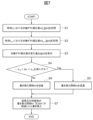
- FIG. 11 is a flowchart showing a process of optimizing a rewrite frequency according to the first embodiment.
- 13 is a graph showing threshold values set in a determination unit according to the second embodiment; 13 is a graph showing an extension time function set in a determination unit according to the third embodiment. 13 is a graph showing a shortened time function set in a determination unit according to the third embodiment.
- FIG. 13 is a diagram showing the configuration of a vehicle electronic device according to a fourth embodiment. 13 is a table for explaining optimization of rewrite frequency according to the fourth embodiment; 13 is a graph showing an extension time function set in a determination unit according to the fourth embodiment.
- 13 is a graph showing a shortened time function set in a determination unit according to the fourth embodiment; 13 is a flowchart showing a process of optimizing a rewrite frequency according to a fourth embodiment. 13 is a graph showing an extension time function set in a determination unit according to the fifth embodiment. 13 is a graph showing a shortened time function set in a determination unit according to the fifth embodiment.
- FIG. 1 is a diagram showing a configuration of an in-vehicle electronic device 1 according to the embodiment 1.
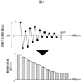
- Fig. 2 is a diagram for explaining optimization of the rewrite frequency.
- the car electronic device 1 detects objects around the vehicle and measures the distance to the objects by utilizing the parallax of overlapping areas of image data captured by multiple cameras 11, 12 arranged at a predetermined horizontal interval.
- the car electronic device 1 shown in FIG. 1 includes the cameras 11, 12 and an image processing device 20 that processes the image data captured by the cameras 11, 12.
- the image processing device 20 is configured, for example, by a computer system equipped with an arithmetic processing device 30 including a CPU, RAM, and ROM, a data storage device 40, and a memory 50.
- the image processing device 20 realizes various functions of the image processing device 20 by the CPU executing programs stored in the ROM.
- the calculation processing device 30 has an image data acquisition unit 31, a calibration unit 32, a calculation unit 33, a determination unit 34, and a control unit 35.
- the image data acquisition unit 31 acquires image data from the cameras 11 and 12.
- the calibration unit 32 performs camera calibration, including the calculation of an optical axis shift correction value, using the image data acquired by the image data acquisition unit 31.
- the camera calibration can be performed by a known method.
- the calibration unit 32 stores the calculated optical axis shift correction value in the data storage device 40.
- the data storage device 40 is composed of a volatile memory.
- the calculation unit 33 calculates the amount of change in the optical axis shift correction value stored in the data storage device 40.
- the determination unit 34 determines the rewrite frequency based on the amount of change in the optical axis shift correction value calculated by the calculation unit 33. Details of the calculation unit 33 and the determination unit 34 will be described later with reference to Figures 3 to 6.
- the control unit 35 saves the optical axis deviation correction value stored in the data storage device 40 in the memory 50 according to the rewrite frequency determined by the determination unit 34.
- the memory 50 is composed of a non-volatile memory.
- the memory 50 may be composed of a NAND type non-volatile memory.
- the NAND type non-volatile memory has fewer rewrite count limitations than the NOR type, it is cheaper than the NOR type.
- Figure 3 is a graph showing the progress of the optical axis deviation correction value when the change in the optical axis deviation correction value is small.
- the vertical axis of Figure 3 shows the optical axis deviation correction value, and the horizontal axis of Figure 3 shows time.
- the change amount ⁇ x in the optical axis shift correction value is expressed as the difference between x( tn+1 ) and x( tn ).
- FIG. 4 is a graph showing the relationship between the amount of change in the optical axis deviation correction value and the threshold value in the case shown in FIG. 3.
- the vertical axis of FIG. 4 shows the amount of change in the optical axis deviation correction value
- the horizontal axis of FIG. 4 shows time.
- the change amount ⁇ x of the optical axis shift correction value at time t n+1 is within the range of the threshold values - ⁇ th to ⁇ th .
- the fact that the change amount ⁇ x of the optical axis shift correction value is within the range of the threshold values - ⁇ th to ⁇ th satisfies the condition of formula (2), and indicates that the magnitude of the change amount ⁇ x is less than the threshold value ⁇ th .
- the threshold values - ⁇ th and ⁇ th are preset in the determination unit 34.
- the determination unit 34 extends the rewrite interval tw, which is the time interval for saving the optical axis shift correction value in the memory 50, by the extension time n [min] as shown in formula (3), to set the extended rewrite interval tw'.
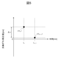
- FIG. 5 is a graph showing the change in the optical axis deviation correction value when the change in the optical axis deviation correction value is large.
- the vertical axis of FIG. 5 shows the optical axis deviation correction value, and the horizontal axis of FIG. 5 shows time.
- the change amount ⁇ x of the optical axis shift correction value is expressed as the difference between x( tn+1 ) and x( tn ), similar to the case shown in Fig. 3.
- the calculation unit 33 calculates the change amount ⁇ x of the optical axis shift correction value using formula (1), similar to the case shown in Fig. 3.
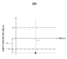
- FIG. 6 is a graph showing the relationship between the amount of change in the optical axis deviation correction value and the threshold value in the case shown in FIG. 5.
- the vertical axis of FIG. 6 shows the amount of change in the optical axis deviation correction value
- the horizontal axis of FIG. 6 shows time.
- the determination unit 34 extends the rewrite interval tw to reduce the frequency of rewriting the optical axis shift correction value to the memory 50.
- the determination unit 34 shortens the rewrite interval tw to increase the frequency of rewriting the optical axis shift correction value to the memory 50.
- step S1 the calculation processing device 30 stores the optical axis deviation correction value x(t n ) at time t n in the data storage device 40.
- step S2 the calculation processing device 30 stores the optical axis deviation correction value x(t n+1 ) at time t n+1 in the data storage device 40.
- step S3 the calculation processing device 30 calculates the amount of change ⁇ x in the stored optical axis deviation correction value.
- step S4 the arithmetic processing device 30 judges whether the calculated change amount ⁇ x of the optical axis deviation correction value satisfies - ⁇ th ⁇ ⁇ x ⁇ ⁇ th . If the change amount ⁇ x satisfies - ⁇ th ⁇ ⁇ x ⁇ ⁇ th , that is, if the magnitude of the change amount ⁇ x is less than the threshold value ⁇ th , the arithmetic processing device 30 proceeds to step S5. If the change amount ⁇ x does not satisfy - ⁇ th ⁇ ⁇ x ⁇ ⁇ th , that is, if the magnitude of the change amount ⁇ x is equal to or greater than the threshold value ⁇ th , the arithmetic processing device 30 proceeds to step S6.
- step S5 the calculation processing device 30 extends the rewrite interval tw.
- step S6 the calculation processing device 30 shortens the rewrite interval tw.
- step S7 the arithmetic processing device 30 rewrites the optical axis deviation correction value in the memory 50 after the extended or shortened rewrite interval tw' or tw'' has elapsed.
- the arithmetic processing device 30 saves the optical axis deviation correction value stored in the data storage device 40 in the memory 50 after the extended or shortened rewrite interval tw' or tw'' has elapsed. Thereafter, the arithmetic processing device 30 ends this process.
- the vehicle electronic device 1 changes the rewrite frequency, which is the frequency at which the correction values for correcting the optical axis misalignment of the cameras 11 and 12 in the image data captured by the cameras 11 and 12 are stored in the memory 50, based on the amount of change in the correction values.
- the car electronic device 1 according to the first embodiment can reduce the rewrite frequency when the change amount of the optical axis shift correction value is small, for example, and therefore can reduce the number of rewrites of the memory 50. Therefore, the car electronic device 1 according to the first embodiment can suppress the number of rewrites of the memory 50 exceeding the rewrite limit, which can cause the data retention reliability of the memory 50 to be impaired. At the same time, the car electronic device 1 according to the first embodiment can increase the rewrite frequency when the change amount of the optical axis shift correction value is large, for example, and therefore can back up the latest optical axis shift correction value corresponding to the newest optical axis shift as much as possible.
- the car electronic device 1 according to the first embodiment can correct the optical axis shift using the latest optical axis shift correction value, and therefore can suppress the deterioration of sensing accuracy due to the correction of the optical axis shift using the old optical axis shift correction value.
- the car electronic device 1 according to the first embodiment can optimize the rewrite frequency of the optical axis shift correction value to the memory 50 according to the change amount of the optical axis shift correction value. Therefore, according to the first embodiment, it is possible to provide a car electronic device 1 capable of optimizing the frequency of rewriting the correction value for correcting the optical axis shift to the memory 50.
- the vehicle electronic device 1 includes cameras 11 and 12, and an image processing device 20 that processes image data captured by the cameras 11 and 12.
- the image processing device 20 includes a memory 50, an image data acquisition unit 31 that acquires image data from the cameras 11 and 12, a calibration unit 32 that performs calibration including the calculation of an optical axis shift correction value, a calculation unit 33 that calculates the amount of change in the calculated optical axis shift correction value, a determination unit 34 that determines the rewrite frequency based on the amount of change in the calculated optical axis shift correction value, and a control unit 35 that stores the optical axis shift correction value in the memory 50 according to the determined rewrite frequency.
- the in-vehicle electronic device 1 according to the first embodiment can optimize the rewrite frequency by incorporating the calculation unit 33, the determination unit 34, and the control unit 35 into the image processing device 20 of the existing stereo camera device. Therefore, the in-vehicle electronic device 1 according to the first embodiment can easily optimize the rewrite frequency of the optical axis deviation correction value in the memory 50.
- the decision unit 34 when the magnitude of the change in the optical axis shift correction value is less than the threshold value, the decision unit 34 extends the rewrite interval, which is the time interval for storing the optical axis shift correction value in the memory 50, to reduce the rewrite frequency, and when the magnitude of the change in the optical axis shift correction value is equal to or greater than the threshold value, the decision unit 34 shortens the rewrite interval to increase the rewrite frequency.
- the car electronic device 1 according to the first embodiment can reduce the number of times the memory 50 is rewritten to ensure reliable data retention, while backing up the latest optical axis shift correction value and reliably suppressing deterioration of sensing accuracy. Therefore, the car electronic device 1 according to the first embodiment can reliably optimize the frequency of rewriting the optical axis shift correction value to the memory 50.
- the memory 50 is a NAND type non-volatile memory.
- the car electronic device 1 according to the first embodiment can use a NAND type non-volatile memory as the memory 50 for storing the optical axis deviation correction value, which has been difficult to adopt in conventional stereo camera devices because it is cheaper than a NOR type but has fewer limitations on the number of times it can be rewritten.
- the cameras 11 and 12 are multiple cameras provided in a stereo camera device.
- the car electronic device 1 according to the first embodiment can back up the latest optical axis shift correction value corresponding to the newest optical axis shift as much as possible in a stereo camera device in which optical axis shift is more likely to directly lead to deterioration in sensing accuracy than in a monocular camera device. Therefore, the car electronic device 1 according to the first embodiment can optimize the frequency of rewriting the optical axis shift correction value to the memory 50 so that the sensing accuracy in the stereo camera device does not deteriorate.
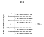
- Fig. 8 is a graph showing the threshold values set in the determination unit 34 according to the embodiment 2.
- the vertical axis of Fig. 8 indicates the amount of change in the optical axis deviation correction value, and the horizontal axis of Fig. 8 indicates time.
- the thresholds ⁇ th and - ⁇ th are preset.
- the threshold ⁇ th is set to a value larger than the threshold ⁇ th .
- the condition regarding the threshold ⁇ th is expressed as in Equation (5). ⁇ th ⁇ x ⁇ th ... (5)
- the determination unit 34 determines the rewrite interval tw based on the conditions of the formulas (2) and (5) as follows. When the condition of the formula (2) is satisfied, the determination unit 34 extends the rewrite interval tw by an extension time n [min], and sets the extended rewrite interval as tw'. If the condition of the formula (5) is not satisfied, the determination unit 34 shortens the rewrite interval tw by the shortening time m [min], and sets the shortened rewrite interval as tw''. When the condition of the formula (2) is not satisfied and the condition of the formula (5) is satisfied, the determination unit 34 maintains the current rewriting interval tw.
- the car electronic device 1 according to the second embodiment can not only extend or shorten the rewrite interval but also maintain the status quo, so that the rewrite frequency can not only be lowered or increased but also maintained as it is. Therefore, the car electronic device 1 according to the second embodiment can optimize the rewrite frequency of the optical axis deviation correction value in the memory 50 with greater precision than the first embodiment.
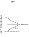
- Fig. 9 is a graph showing an extension time function set in the determination unit 34 according to the embodiment 3.
- the vertical axis of Fig. 9 indicates the amount of change in the optical axis deviation correction value
- the horizontal axis of Fig. 9 indicates the extension time.
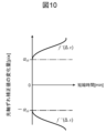
- Fig. 10 is a graph showing a reduction time function set in the determination unit 34 according to the embodiment 3.
- the vertical axis of Fig. 10 indicates the amount of change in the optical axis deviation correction value
- the horizontal axis of Fig. 10 indicates the reduction time.
- the extension time n and shortening time m which are the amounts of change in the rewrite interval tw, are constant values.
- an extension time function f( ⁇ x) as shown in FIG. 9 is defined for the extension time n, which is the amount of change in the rewrite interval tw.
- shortening time functions f'( ⁇ x) and f''( ⁇ x) as shown in FIG. 10 are defined for the shortening time m, which is the amount of change in the rewrite interval tw.
- the extension time n and shortening time m which are the amounts of change in the rewrite interval tw, can be variable values.
- the determination unit 34 calculates the shortened time m by substituting the change amount ⁇ x of the optical axis deviation correction value into the shortened time functions f'( ⁇ x) and f''( ⁇ x) as shown in formulas (7) and (8). Then, the determination unit 34 according to the third embodiment determines the shortened rewriting interval tw'' from formula (4).
- m f'( ⁇ x) ... (7)
- m f ′′( ⁇ x) ... (8)
- a function indicating the relationship between the amount of change in the optical axis deviation correction value and the amount of change in the rewrite interval is preset in the determination unit 34 according to the third embodiment.
- the determination unit 34 according to the third embodiment determines the rewrite frequency by substituting the amount of change in the optical axis deviation correction value calculated by the calculation unit 33 into the function to calculate the amount of change in the rewrite interval.
- the car electronic device 1 according to the third embodiment can set the change amount of the rewrite interval to a variable value that varies according to the amount of change in the optical axis shift correction value, and can therefore be optimized more appropriately according to the amount of change in the optical axis shift correction value. Therefore, the car electronic device 1 according to the third embodiment can optimize the frequency of rewriting the optical axis shift correction value to the memory 50 with even greater precision than the first embodiment.
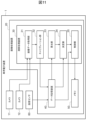
- Fig. 11 is a diagram showing a configuration of the vehicle electronic device 1 according to the fourth embodiment.
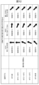
- Fig. 12 is a table for explaining the optimization of the rewrite frequency according to the fourth embodiment.
- the car electronic device 1 of Example 4 determines the rewrite frequency taking into account the temperature of the car electronic device 1.
- the car electronic device 1 according to the fourth embodiment further includes a temperature sensor 60 for detecting the temperature of the car electronic device 1, as shown in FIG. 11.
- the temperature of the car electronic device 1 detected by the temperature sensor 60 may be the temperature of the cameras 11 and 12, the temperature of the memory 50, or the ambient temperature of these.
- the temperature sensor 60 is composed of various temperature sensors including a thermistor.
- the temperature detected by the temperature sensor 60 is stored in the data storage device 40.
- the decision unit 34 according to the fourth embodiment decides the rewrite frequency based on the amount of change in the optical axis deviation correction value and the temperature of the car electronic device 1. Specifically, the decision unit 34 according to the fourth embodiment makes the rewrite frequency lower when the temperature of the car electronic device 1 is high than when the temperature of the car electronic device 1 is normal temperature.
- the car electronic device 1 of Example 4 can reliably reduce the number of times the memory 50 is rewritten at high temperatures when the data retention reliability of the memory 50 is easily impaired, thereby ensuring data retention reliability.
- the car electronic device 1 of Example 4 can back up the latest optical axis shift correction value to suppress deterioration of sensing accuracy. Therefore, the car electronic device 1 of Example 4 can optimize the frequency of rewriting the optical axis shift correction value to the memory 50 with even greater accuracy than Example 1.
- FIG. 12 shows how the rewrite interval tw is changed for each section of the temperature T of the vehicle electronic device 1 when the magnitude of the change amount ⁇ x of the optical axis shift correction value is small (for example, less than 1.0 pix), large (for example, 1.0 pix or more and 2.0 pix or less), and extremely large (for example, more than 2.0 pix ).
- small for example, less than 1.0 pix
- large for example, 1.0 pix or more and 2.0 pix or less
- extremely large for example, more than 2.0 pix
- the boundary value (for example, 1.0 pix) that distinguishes between the case where the magnitude of the change amount ⁇ x of the optical axis shift correction value is small and the case where the magnitude of the change amount ⁇ x of the optical axis shift correction value is large and the case where the magnitude of the change amount ⁇ x of the optical axis shift correction value is extremely large (for example, 2.0 pix) may be the limit value of the magnitude of the change amount ⁇ x of the optical axis shift correction value corresponding to the limit value of the allowable sensing accuracy.
- the amount of change in the rewrite interval tw is expressed as either “Medium Extension”, “Large Extension”, “Extra Large Extension”, “Medium Shortening”, “Small Shortening”, or “Minimal Shortening”.
- “Large Extension” means that the rewrite interval tw is extended, and that the extension time, which is the amount of change in the rewrite interval tw, is large.
- “Minimal Shortening” means that the rewrite interval tw is shortened, and that the shortening time, which is the amount of change in the rewrite interval tw, is extremely small.
- the decision unit 34 when the magnitude of the change amount ⁇ x of the optical axis shift correction value is less than the threshold value ( ⁇ th ), the decision unit 34 according to the fourth embodiment extends the rewrite interval tw and makes the extension time, which is the amount of change in the rewrite interval tw when the temperature T of the car electronic device 1 is high, longer than when the temperature T of the car electronic device 1 is at room temperature, thereby reducing the rewrite frequency.
- the decision unit 34 when the magnitude of the change amount ⁇ x of the optical axis shift correction value is equal to or greater than the threshold value ( ⁇ th ), the decision unit 34 according to the fourth embodiment shortens the rewrite interval tw and makes the shortening time, which is the amount of change in the rewrite interval tw when the temperature T of the car electronic device 1 is high, shorter than when the temperature T of the car electronic device 1 is at room temperature, thereby increasing the rewrite frequency.
- the car electronic device 1 of Example 4 can determine the rewrite interval so as to ensure data retention reliability and suppress deterioration of sensing accuracy, depending on the amount of change in the optical axis shift correction value and the temperature of the car electronic device 1. Therefore, the car electronic device 1 of Example 4 can optimize the rewrite frequency more appropriately than Example 1. Therefore, the car electronic device 1 of Example 4 can optimize the rewrite frequency of the optical axis shift correction value to the memory 50 more accurately than Example 1.
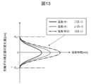
- FIG. 13 is a graph showing an extension time function set in the determination unit 34 according to the fourth embodiment.
- the vertical axis of FIG. 13 indicates the amount of change in the optical axis deviation correction value
- the horizontal axis of FIG. 13 indicates the extension time.
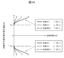
- FIG. 14 is a graph showing a reduction time function set in the determination unit 34 according to the fourth embodiment.
- the vertical axis of FIG. 14 indicates the amount of change in the optical axis deviation correction value
- the horizontal axis of FIG. 14 indicates the reduction time.
- the extension time function f( ⁇ x) is an example of an extension time function used in the case of "Extension (medium)” shown in FIG. 12.
- the extension time function g( ⁇ x) is an example of an extension time function used in the case of "Extension (large)” shown in FIG. 12.
- the extension time function h( ⁇ x) is an example of an extension time function used in the case of "Extra Large” shown in FIG. 12.
- the shortening time functions f'( ⁇ x) and f"( ⁇ x) are examples of shortening time functions used in the case of "Shortening (medium)" shown in FIG. 12.
- the shortening time functions g'( ⁇ x) and g"( ⁇ x) are examples of shortening time functions used in the case of "Shortening (small)” shown in FIG. 12.
- the shortening time functions h'( ⁇ x) and h"( ⁇ x) are examples of shortening time functions used in the case of "Shortening (minimal)" shown in FIG. 12.
- an extension time function as shown in FIG. 13 and a shortening time function as shown in FIG. 14 may be defined for the extension time and shortening time, which are the change amounts of the rewrite interval.
- the car electronic device 1 according to the fourth embodiment can set the extension time and shortening time, which are the change amounts of the rewrite interval, to variable values that change according to the change amount of the optical axis shift correction value and the temperature of the car electronic device 1. Therefore, the car electronic device 1 according to the fourth embodiment can further appropriately optimize the change amount of the rewrite interval according to the change amount of the optical axis shift correction value and the temperature of the car electronic device 1. Therefore, the car electronic device 1 according to the fourth embodiment can optimize the frequency of rewriting the optical axis shift correction value to the memory 50 with even greater accuracy than the first and third embodiments.
- FIG. 15 is a flowchart showing the rewrite frequency optimization process according to the fourth embodiment.
- step S11 the calculation processing device 30 stores the optical axis deviation correction value x(t n ) at time t n in the data storage device 40.
- step S12 the calculation processing device 30 stores the optical axis shift correction value x(t n+1 ) at time t n+1 in the data storage device 40.
- step S13 the calculation processing device 30 calculates the amount of change ⁇ x in the stored optical axis deviation correction value.
- step S14 the arithmetic processing unit 30 stores in the data storage unit 40 the temperature T of the vehicle electronic device 1 at the time t n+1 .
- step S15 the arithmetic processing device 30 judges whether the calculated change amount ⁇ x of the optical axis shift correction value satisfies - ⁇ th ⁇ ⁇ x ⁇ ⁇ th . If the change amount ⁇ x satisfies - ⁇ th ⁇ ⁇ x ⁇ ⁇ th , that is, if the magnitude of the change amount ⁇ x is less than the threshold value ⁇ th , the arithmetic processing device 30 proceeds to step S16. If the change amount ⁇ x does not satisfy - ⁇ th ⁇ ⁇ x ⁇ ⁇ th , that is, if the magnitude of the change amount ⁇ x is equal to or greater than the threshold value ⁇ th , the arithmetic processing device 30 proceeds to step S18.
- step S16 the calculation processing device 30 determines the extension time function to be used from the stored temperature T of the vehicle electronic device 1.
- step S17 the calculation processing device 30 extends the rewrite interval tw according to the determined extension time function.
- step S18 the calculation processing device 30 determines the shortened time function to be used from the stored temperature T of the vehicle electronic device 1.
- step S19 the calculation processing device 30 shortens the rewrite interval tw according to the determined shortened time function.
- step S20 the arithmetic processing device 30 rewrites the memory 50 after the extended or shortened rewrite interval tw' or tw'' has elapsed.
- the arithmetic processing device 30 saves the optical axis deviation correction value stored in the data storage device 40 in the memory 50 after the extended or shortened rewrite interval tw' or tw'' has elapsed. Thereafter, the arithmetic processing device 30 ends this process.
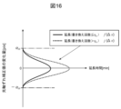
- Fig. 16 is a graph showing an extension time function set in the determination unit 34 according to Example 5.
- the vertical axis of Fig. 16 indicates the amount of change in the optical axis deviation correction value
- the horizontal axis of Fig. 16 indicates the extension time.
- Fig. 17 is a graph showing a reduction time function set in the determination unit 34 according to Example 5.
- the vertical axis of Fig. 17 indicates the amount of change in the optical axis deviation correction value
- the horizontal axis of Fig. 17 indicates the reduction time.
- the extension time function f( ⁇ x) is an example of an extension time function used when the number of times the memory 50 is rewritten is equal to or less than a predetermined value ⁇ th .
- the extension time function j( ⁇ x) is an example of an extension time function used when the number of times the memory 50 is rewritten exceeds a predetermined value ⁇ th .
- the shortening time functions f'( ⁇ x) and f''( ⁇ x) are examples of shortening time functions used when the number of times the memory 50 is rewritten is equal to or less than a predetermined value ⁇ th .
- the shortening time functions j'( ⁇ x) and j''( ⁇ x) are examples of shortening time functions used when the number of times the memory 50 is rewritten exceeds a predetermined value ⁇ th .
- the determination unit 34 can reduce the number of times the memory 50 is rewritten by the following method.
- the optical axis deviation correction value is not rewritten (stored) in the memory 50. Only the rewrite interval tw is extended, and the rewrite interval tw is not shortened.
- the extension time function f( ⁇ x) and the shortening time functions f'( ⁇ x) and f''( ⁇ x) set in the determination unit 34 in Example 3 are changed to the extension time function j( ⁇ x) and the shortening time functions j'( ⁇ x) and j''( ⁇ x) shown in Figures 16 and 17.
- the car electronic device 1 of Example 5 can further reduce the number of times the memory 50 is rewritten compared to Example 3, thereby further ensuring data retention reliability.
- the car electronic device 1 of Example 5 can back up the latest optical axis shift correction value and suppress deterioration of sensing accuracy. Therefore, the car electronic device 1 of Example 5 can optimize the frequency of rewriting the optical axis shift correction value to the memory 50 with even greater accuracy than Example 3.
- the rewrite interval is extended and shortened, but the vehicle electronic device 1 may only extend the rewrite interval and not shorten it. Also, the vehicle electronic device 1 may set at least one of a lower limit and an upper limit to the rewrite interval and change the frequency of rewriting the optical axis deviation correction value to the memory 50 within a predetermined range.
- the car electronic device 1 may also rewrite the memory 50 (save the optical axis deviation correction value in the memory 50) during at least one of the periods when the speed of the vehicle in which the car electronic device 1 is mounted is zero [km/h] and when the ignition of the vehicle is off. Since the processing load of the arithmetic processing device 30 is large while the vehicle is running, rewriting the memory 50 while the vehicle is running increases the amount of heat generated by the arithmetic processing device 30, which may adversely affect the data retention reliability and sensing accuracy of the memory 50.
- the car electronic device 1 rewrites the memory 50 while the vehicle is stopped and the processing load of the arithmetic processing device 30 is small, thereby suppressing an increase in the amount of heat generated by the arithmetic processing device 30 and suppressing adverse effects on the data retention reliability and sensing accuracy of the memory 50.
- the car electronic device 1 may change the storage area of the optical axis deviation correction value to another storage area within the memory 50 or another storage area outside the memory 50. In this way, the car electronic device 1 may reduce the number of times the memory 50 is rewritten.
- the present invention is not limited to the above-described embodiments, and includes various modified examples.
- the above-described embodiments have been described in detail to clearly explain the present invention, and are not necessarily limited to those having all of the configurations described. It is also possible to replace part of the configuration of one embodiment with the configuration of another embodiment, and it is also possible to add the configuration of another embodiment to the configuration of one embodiment. It is also possible to add, delete, or replace part of the configuration of each embodiment with other configurations.
- the above-mentioned configurations, functions, processing units, processing means, etc. may be realized in part or in whole by hardware, for example by designing them as integrated circuits.
- the above-mentioned configurations, functions, etc. may also be realized by software, in which a processor interprets and executes a program that realizes each function.
- Information on the programs, tapes, files, etc. that realize each function can be stored in a memory, a recording device such as a hard disk or SSD (solid state drive), or a recording medium such as an IC card, SD card, or DVD.
- control lines and information lines shown are those considered necessary for the explanation, and do not necessarily show all control lines and information lines on the product. In reality, it can be assumed that almost all components are interconnected.
Landscapes
- Engineering & Computer Science (AREA)
- Multimedia (AREA)
- Signal Processing (AREA)
- Traffic Control Systems (AREA)
- Testing, Inspecting, Measuring Of Stereoscopic Televisions And Televisions (AREA)
Abstract
光軸ずれを補正する補正値をメモリに書き換える頻度を最適化することが可能な車用電子装置を提供することを目的とする。車用電子装置1は、カメラ11,12によって撮影された画像データにおいてカメラ11,12の光軸ずれを補正する補正値をメモリ50に保存する頻度である書き換え頻度を、当該補正値の変化量に基づいて変更する。車用電子装置1は、カメラ11,12と、画像処理装置20と、を備えてもよい。画像処理装置20は、メモリ50と、カメラ11,12から画像データを取得する画像データ取得部31と、光軸ずれ補正値の演算を含むキャリブレーションを行うキャリブレーション部32と、演算された光軸ずれ補正値の変化量を算出する算出部33と、算出された光軸ずれ補正値の変化量に基づいて書き換え頻度を決定する決定部34と、決定された書き換え頻度に応じて光軸ずれ補正値をメモリ50に保存する制御部35と、を有してもよい。
Description
本発明は、車用電子装置に関する。
車用電子装置であるステレオカメラ装置では、時間経過に伴って光軸ずれが発生する。光軸ずれは、カメラのレンズ中心軸が初期位置からずれたり、左右のカメラの間でレンズ中心軸がずれたりすることである。光軸ずれが増大すると、ステレオカメラ装置のセンシング精度が悪化する。そこで、ステレオカメラ装置では、定期的に光軸ずれの補正を行い、光軸ずれの補正値を不揮発性メモリに保存して、当該補正値をバックアップしている。
例えば、特許文献1には、パラメータ記憶部に記憶されたカメラパラメータを更新すると共に、車両移動パラメータを更新するパラメータ更新部を備えるカメラキャリブレーション装置が開示されている。このパラメータ更新部は、各カメラの画像において、ホモグラフィー行列によって変換される特徴点の位置が、路面フロー抽出部で求めた特徴点のフローと整合するように、カメラパラメータ及び車両移動パラメータの最適解を求める機能を有する。
光軸ずれの補正値が保存される不揮発性メモリでは、生涯のデータ書き換え回数が、書き換え回数制限を超えないよう考慮される必要がある。書き換え回数が書き換え回数制限を超えてしまうと、不揮発性メモリにはデータ化け等が発生し、不揮発性メモリのデータ保持信頼性が損なわれる懸念がある。特許文献1に開示されたカメラキャリブレーション装置は、カメラパラメータの書き換え頻度に関して何ら考慮されておらず、メモリの書き換え回数制限を超えてしまう懸念がある。
本発明は、上記に鑑みてなされたものであり、光軸ずれを補正する補正値をメモリに書き換える頻度を最適化することが可能な車用電子装置を提供することを目的とする。
上記課題を解決するために、本発明に係る車用電子装置は、カメラによって撮影された画像データにおいて前記カメラの光軸ずれを補正する補正値をメモリに保存する頻度である書き換え頻度を、前記補正値の変化量に基づいて変更することを特徴とする。
本発明によれば、光軸ずれを補正する補正値をメモリに書き換える頻度を最適化することが可能な車用電子装置を提供することができる。
上記以外の課題、構成および効果は、以下の実施形態の説明により明らかにされる。
上記以外の課題、構成および効果は、以下の実施形態の説明により明らかにされる。
以下、本発明の実施形態について図面を用いて説明する。なお、各実施形態において同一の符号を付された構成については、特に言及しない限り、各実施形態において同様の機能を有し、その説明を省略する。
[実施例1]
図1は、実施例1に係る車用電子装置1の構成を示す図である。図2は、書き換え頻度の最適化を説明する図である。
図1は、実施例1に係る車用電子装置1の構成を示す図である。図2は、書き換え頻度の最適化を説明する図である。
車用電子装置1は、車両に搭載され、車両周辺を監視するセンサ装置の一種である。車用電子装置1は、レンズ又はミラー等の光学系を有するセンサ装置である。車用電子装置1は、単眼カメラ装置であってもよいし、複数のカメラが設けられたステレオカメラ装置であってもよい。本実施形態では、車用電子装置1がステレオカメラ装置であるとして説明する。
車用電子装置1は、水平方向に所定間隔をあけて配置された複数のカメラ11,12によって撮影された画像データの重複領域の視差を利用して、車両周辺の物体の検知及び物体までの距離計測を行う。図1に示す車用電子装置1は、カメラ11,12と、カメラ11,12によって撮影された画像データを処理する画像処理装置20と、を備える。
画像処理装置20は、例えば、CPU、RAM及びROMを含む演算処理装置30と、データ記憶装置40及びメモリ50と、を備えたコンピュータシステムによって構成される。画像処理装置20は、ROMに記憶されたプログラムをCPUが実行することによって画像処理装置20の各種機能を実現する。
演算処理装置30は、図2に示すように、カメラ11,12によって撮影された画像データにおいてカメラ11,12の光軸ずれを補正する補正値(以下「光軸ずれ補正値」とも称する)をメモリ50に保存する頻度(以下「書き換え頻度」とも称する)を、光軸ずれ補正値の時間的な変化量に基づいて変更する。図2では、時間経過に伴って光軸ずれ補正値が小さくなる場合に、メモリ50への光軸ずれ補正値の書き換え頻度を時間経過に伴って低くすることを示している。
演算処理装置30は、画像データ取得部31と、キャリブレーション部32と、算出部33と、決定部34と、制御部35と、を有する。
画像データ取得部31は、カメラ11,12から画像データを取得する。キャリブレーション部32は、画像データ取得部31により取得された画像データを用いて、光軸ずれ補正値の演算を含むカメラキャリブレーションを行う。カメラキャリブレーションは、公知の手法によって、カメラキャリブレーションを行うことができる。キャリブレーション部32は、演算された光軸ずれ補正値をデータ記憶装置40に記憶する。データ記憶装置40は、揮発性メモリによって構成される。
算出部33は、データ記憶装置40に記憶された光軸ずれ補正値の変化量を算出する。決定部34は、算出部33により算出された光軸ずれ補正値の変化量に基づいて、書き換え頻度を決定する。算出部33及び決定部34の詳細については、図3~図6を用いて後述する。
制御部35は、決定部34により決定された書き換え頻度に応じて、データ記憶装置40に記憶された光軸ずれ補正値をメモリ50に保存する。メモリ50は、不揮発性メモリによって構成される。特に、メモリ50は、NAND型の不揮発性メモリによって構成されてもよい。NAND型の不揮発性メモリは、書き換え回数制限がNOR型よりも少ないものの、価格がNOR型よりも安い。
図3は、光軸ずれ補正値の変化量が小さい場合における光軸ずれ補正値の推移を示すグラフである。図3の縦軸は光軸ずれ補正値を示し、図3の横軸は時間を示す。
時刻tnにおける光軸ずれ補正値をx(tn)とし、時刻tn+1における光軸ずれ補正値をx(tn+1)とする場合、光軸ずれ補正値の変化量Δxは、x(tn+1)とx(tn)との差分値として表される。算出部33は、式(1)を用いて光軸ずれ補正値の変化量Δxを算出する。
Δx=x(tn+1)-x(tn) …(1)
Δx=x(tn+1)-x(tn) …(1)
図4は、図3に示す場合における光軸ずれ補正値の変化量と閾値との関係を示すグラフである。図4の縦軸は光軸ずれ補正値の変化量を示し、図4の横軸は時間を示す。
図4では、時刻tn+1における光軸ずれ補正値の変化量Δxが、閾値-αthからαthの範囲内であることを示している。光軸ずれ補正値の変化量Δxが閾値-αthからαthの範囲内であることは、式(2)の条件を満たすことであり、当該変化量Δxの大きさが閾値αth未満であることを示している。閾値-αth及びαthは、決定部34に予め設定されている。
光軸ずれ補正値の変化量Δxが式(2)の条件を満たす場合、決定部34は、式(3)に示すように、光軸ずれ補正値をメモリ50に保存する時間間隔である書き換え間隔twを延長時間n[min]だけ延長し、延長後の書き換え間隔tw’とする。これによって、決定部34は、メモリ50への光軸ずれ補正値の書き換え頻度を変更前より低くすることができる。延長時間nは、書き換え間隔twの変更量である。
-αth<Δx<αth …(2)
tw’=tw+n …(3)
-αth<Δx<αth …(2)
tw’=tw+n …(3)
図5は、光軸ずれ補正値の変化量が大きい場合における光軸ずれ補正値の推移を示すグラフである。図5の縦軸は光軸ずれ補正値を示し、図5の横軸は時間を示す。
時刻tnにおける光軸ずれ補正値をx(tn)とし、時刻tn+1における光軸ずれ補正値をx(tn+1)とする場合、光軸ずれ補正値の変化量Δxは、図3に示す場合と同様に、x(tn+1)とx(tn)との差分値として表される。算出部33は、図3に示す場合と同様に、式(1)を用いて光軸ずれ補正値の変化量Δxを算出する。
図6は、図5に示す場合における光軸ずれ補正値の変化量と閾値との関係を示すグラフである。図6の縦軸は光軸ずれ補正値の変化量を示し、図6の横軸は時間を示す。
図6では、時刻tn+1における光軸ずれ補正値の変化量Δxが、閾値-αthからαthの範囲以外であることを示している。光軸ずれ補正値の変化量Δxが閾値-αthからαthの範囲以外であることは、式(2)の条件を満たさないことであり、当該変化量Δxの大きさが閾値αth以上であることを示している。
光軸ずれ補正値の変化量Δxが式(2)の条件を満たさない場合、決定部34は、式(4)に示すように、書き換え間隔twを短縮時間m[min]だけ短縮し、短縮後の書き換え間隔tw’’とする。これによって、決定部34は、メモリ50への光軸ずれ補正値の書き換え頻度を変更前より高くすることができる。短縮時間mは、書き換え間隔twの変更量である。
tw’’=tw+m …(4)
tw’’=tw+m …(4)
このように、決定部34は、光軸ずれ補正値の変化量Δxの大きさが閾値αth未満である場合、書き換え間隔twを延長して、メモリ50への光軸ずれ補正値の書き換え頻度を低くする。決定部34は、光軸ずれ補正値の変化量Δxの大きさが閾値αth以上である場合、書き換え間隔twを短縮して、メモリ50への光軸ずれ補正値の書き換え頻度を高くする。
図7は、実施例1に係る書き換え頻度の最適化処理を示すフローチャートである。
ステップS1において、演算処理装置30は、時刻tnにおける光軸ずれ補正値x(tn)をデータ記憶装置40に記憶する。
ステップS2において、演算処理装置30は、時刻tn+1における光軸ずれ補正値x(tn+1)をデータ記憶装置40に記憶する。
ステップS3において、演算処理装置30は、記憶された光軸ずれ補正値の変化量Δxを算出する。
ステップS4において、演算処理装置30は、算出された光軸ずれ補正値の変化量Δxが、-αth<Δx<αthを満たすか否かを判定する。変化量Δxが-αth<Δx<αthを満たす場合、すなわち、変化量Δxの大きさが閾値αth未満である場合、演算処理装置30は、ステップS5に移行する。変化量Δxが-αth<Δx<αthを満たさない場合、すなわち、変化量Δxの大きさが閾値αth以上である場合、演算処理装置30は、ステップS6に移行する。
ステップS5において、演算処理装置30は、書き換え間隔twを延長する。
ステップS6において、演算処理装置30は、書き換え間隔twを短縮する。
ステップS7において、演算処理装置30は、延長又は短縮後の書き換え間隔tw’又はtw’’が経過したら、メモリ50への光軸ずれ補正値の書き換えを行う。すなわち、演算処理装置30は、延長又は短縮後の書き換え間隔tw’又はtw’’が経過したら、データ記憶装置40に記憶された光軸ずれ補正値をメモリ50に保存する。その後、演算処理装置30は、本処理を終了する。
以上のように、実施例1に係る車用電子装置1は、カメラ11,12によって撮影された画像データにおいてカメラ11,12の光軸ずれを補正する補正値をメモリ50に保存する頻度である書き換え頻度を、当該補正値の変化量に基づいて変更する。
これにより、実施例1に係る車用電子装置1は、例えば、光軸ずれ補正値の変化量が小さい場合には書き換え頻度を低くすることができるので、メモリ50の書き換え回数を低減することができる。したがって、実施例1に係る車用電子装置1は、メモリ50の書き換え回数が書き換え回数制限を超えてしまい、メモリ50のデータ保持信頼性が損なわれることを抑制することができる。同時に、実施例1に係る車用電子装置1は、例えば、光軸ずれ補正値の変化量が大きい場合には書き換え頻度を高くすることができるので、可能な限り新しい光軸ずれに対応した最新の光軸ずれ補正値をバックアップすることができる。したがって、実施例1に係る車用電子装置1は、最新の光軸ずれ補正値を用いて光軸ずれを補正することができるので、古い光軸ずれ補正値を用いた光軸ずれの補正によってセンシング精度が悪化することを抑制することができる。このように、実施例1に係る車用電子装置1は、光軸ずれ補正値の変化量に応じてメモリ50への光軸ずれ補正値の書き換え頻度を最適化することができる。よって、実施例1によれば、光軸ずれを補正する補正値をメモリ50に書き換える頻度を最適化することが可能な車用電子装置1を提供することができる。
更に、実施例1に係る車用電子装置1は、カメラ11,12と、カメラ11,12によって撮影された画像データを処理する画像処理装置20と、を備える。画像処理装置20は、メモリ50と、カメラ11,12から画像データを取得する画像データ取得部31と、光軸ずれ補正値の演算を含むキャリブレーションを行うキャリブレーション部32と、演算された光軸ずれ補正値の変化量を算出する算出部33と、算出された光軸ずれ補正値の変化量に基づいて書き換え頻度を決定する決定部34と、決定された書き換え頻度に応じて光軸ずれ補正値をメモリ50に保存する制御部35と、を有する。
これにより、実施例1に係る車用電子装置1は、既存のステレオカメラ装置が有する画像処理装置20に算出部33、決定部34及び制御部35を組み込むことによって、書き換え頻度を最適化することができる。したがって、実施例1に係る車用電子装置1は、メモリ50への光軸ずれ補正値の書き換え頻度を容易に最適化することができる。
更に、実施例1に係る車用電子装置1において、決定部34は、光軸ずれ補正値の変化量の大きさが閾値未満である場合、光軸ずれ補正値をメモリ50に保存する時間間隔である書き換え間隔を延長して書き換え頻度を低くし、光軸ずれ補正値の変化量の大きさが閾値以上である場合、書き換え間隔を短縮して書き換え頻度を高くする。
これにより、実施例1に係る車用電子装置1は、メモリ50の書き換え回数を低減してデータ保持信頼性を確実に確保しつつ、最新の光軸ずれ補正値をバックアップしてセンシング精度の悪化を確実に抑制することができる。したがって、実施例1に係る車用電子装置1は、メモリ50への光軸ずれ補正値の書き換え頻度を確実に最適化することができる。
更に、実施例1に係る車用電子装置1において、メモリ50は、NAND型の不揮発性メモリである。
すなわち、実施例1に係る車用電子装置1は、NOR型よりも価格が安い一方で書き換え回数制限が少ないことから従来のステレオカメラ装置では採用が難しかったNAND型の不揮発性メモリを、光軸ずれ補正値を保存するメモリ50として採用することができる。これにより、実施例1に係る車用電子装置1は、メモリ50への光軸ずれ補正値の書き換え頻度を最適化しながら、低コスト化を図ることができる。
更に、実施例1に係る車用電子装置1において、カメラ11,12は、ステレオカメラ装置に設けられた複数のカメラである。
これにより、実施例1に係る車用電子装置1は、単眼カメラ装置よりも光軸ずれがセンシング精度の悪化に直結し易いステレオカメラ装置において、可能な限り新しい光軸ずれに対応した最新の光軸ずれ補正値をバックアップすることができる。したがって、実施例1に係る車用電子装置1は、ステレオカメラ装置においてセンシング精度が悪化しないよう、メモリ50への光軸ずれ補正値の書き換え頻度を最適化することができる。
[実施例2]
図8は、実施例2に係る決定部34に設定された閾値を示すグラフである。図8の縦軸は光軸ずれ補正値の変化量を示し、図8の横軸は時間を示す。
図8は、実施例2に係る決定部34に設定された閾値を示すグラフである。図8の縦軸は光軸ずれ補正値の変化量を示し、図8の横軸は時間を示す。
実施例2に係る決定部34には、図8に示すように、閾値αth,-αthだけでなく閾値βth,-βthが予め設定されている。閾値βthは、閾値αthより大きい値とする。閾値βthに関する条件は、式(5)のように示される。
-βth<Δx<βth …(5)
-βth<Δx<βth …(5)
実施例2に係る決定部34は、式(2)及び式(5)の条件に基づいて、書き換え間隔twを次のように決定する。
・式(2)の条件を満たす場合、決定部34は、書き換え間隔twを延長時間n[min]だけ延長し、延長後の書き換え間隔tw’とする。
・式(5)の条件を満たさない場合、決定部34は、書き換え間隔twを短縮時間m[min]だけ短縮し、短縮後の書き換え間隔tw’’とする。
・式(2)の条件を満たさず、且つ、式(5)の条件を満たす場合、決定部34は、書き換え間隔twを現状維持とする。
・式(2)の条件を満たす場合、決定部34は、書き換え間隔twを延長時間n[min]だけ延長し、延長後の書き換え間隔tw’とする。
・式(5)の条件を満たさない場合、決定部34は、書き換え間隔twを短縮時間m[min]だけ短縮し、短縮後の書き換え間隔tw’’とする。
・式(2)の条件を満たさず、且つ、式(5)の条件を満たす場合、決定部34は、書き換え間隔twを現状維持とする。
実施例2に係る車用電子装置1は、書き換え間隔を延長又は短縮するだけでなく現状維持とすることができるので、書き換え頻度を低く又は高くするだけでなく現状維持とすることができる。したがって、実施例2に係る車用電子装置1は、メモリ50への光軸ずれ補正値の書き換え頻度を、実施例1よりも精度良く最適化することができる。
[実施例3]
図9は、実施例3に係る決定部34に設定された延長時間関数を示すグラフである。図9の縦軸は光軸ずれ補正値の変化量を示し、図9の横軸は延長時間を示す。図10は、実施例3に係る決定部34に設定された短縮時間関数を示すグラフである。図10の縦軸は光軸ずれ補正値の変化量を示し、図10の横軸は短縮時間を示す。
図9は、実施例3に係る決定部34に設定された延長時間関数を示すグラフである。図9の縦軸は光軸ずれ補正値の変化量を示し、図9の横軸は延長時間を示す。図10は、実施例3に係る決定部34に設定された短縮時間関数を示すグラフである。図10の縦軸は光軸ずれ補正値の変化量を示し、図10の横軸は短縮時間を示す。
実施例1に係る決定部34では、書き換え間隔twの変更量である延長時間n及び短縮時間mが一定値であった。これに対し、実施例3に係る決定部34では、書き換え間隔twの変更量である延長時間nに対して、図9に示すような延長時間関数f(Δx)が定義されている。同様に、実施例3に係る決定部34では、書き換え間隔twの変更量である短縮時間mに対して、図10に示すような短縮時間関数f’(Δx)及びf’’(Δx)が定義されている。これによって、実施例3に係る決定部34では、書き換え間隔twの変更量である延長時間n及び短縮時間mを変動値とすることができる。
実施例3に係る決定部34は、式(2)の条件を満たす場合、式(6)に示すように、光軸ずれ補正値の変化量Δxを延長時間関数f(Δx)に代入して、延長時間nを計算する。そして、実施例3に係る決定部34は、式(3)から、延長後の書き換え間隔tw’を決定する。
n=f(Δx) …(6)
n=f(Δx) …(6)
実施例3に係る決定部34は、式(2)の条件を満たさない場合、式(7)及び式(8)に示すように、光軸ずれ補正値の変化量Δxを短縮時間関数f’(Δx)及びf’’(Δx)に代入して、短縮時間mを計算する。そして、実施例3に係る決定部34は、式(4)から、短縮後の書き換え間隔tw’’を決定する。
m=f’(Δx) …(7)
m=f’’(Δx) …(8)
m=f’(Δx) …(7)
m=f’’(Δx) …(8)
このように、実施例3に係る決定部34には、光軸ずれ補正値の変化量と、書き換え間隔の変更量との関係を示す関数が予め設定されている。実施例3に係る決定部34は、算出部33により算出された光軸ずれ補正値の変化量を、当該関数に代入して書き換え間隔の変更量を計算することによって、書き換え頻度を決定する。
これにより、実施例3に係る車用電子装置1は、書き換え間隔の変更量を、光軸ずれ補正値の変化量に応じて変動する変動値とすることができるので、光軸ずれ補正値の変化量に応じて更に適切に最適化することができる。したがって、実施例3に係る車用電子装置1は、メモリ50への光軸ずれ補正値の書き換え頻度を、実施例1よりも更に精度良く最適化することができる。
[実施例4]
図11は、実施例4に係る車用電子装置1の構成を示す図である。図12は、実施例4に係る書き換え頻度の最適化を説明する表である。
図11は、実施例4に係る車用電子装置1の構成を示す図である。図12は、実施例4に係る書き換え頻度の最適化を説明する表である。
メモリ50は、その物理的特性から、常温時よりも高温時のデータ書き換えにおいて、データ化け等が発生し易く、データ保持信頼性が損なわれ易くなる。そこで、実施例4に係る車用電子装置1は、車用電子装置1の温度を考慮して書き換え頻度を決定する。
実施例4に係る車用電子装置1は、図11に示すように、車用電子装置1の温度を検出する温度センサ60を更に備える。温度センサ60によって検出される車用電子装置1の温度は、カメラ11,12の温度、メモリ50の温度、又は、これらの周囲温度であってもよい。温度センサ60は、サーミスタをはじめとする各種の温度センサによって構成される。温度センサ60によって検出された温度は、データ記憶装置40に記憶される。実施例4に係る決定部34は、光軸ずれ補正値の変化量及び車用電子装置1の温度に基づいて、書き換え頻度を決定する。具体的には、実施例4に係る決定部34は、車用電子装置1の温度が高温時の書き換え頻度を、車用電子装置1の温度が常温時の書き換え頻度よりも低くする。
これにより、実施例4に係る車用電子装置1は、メモリ50のデータ保持信頼性が損なわれ易い高温時には、メモリ50の書き換え回数を確実に低減してデータ保持信頼性を確実に確保することができる。同時に、実施例4に係る車用電子装置1は、最新の光軸ずれ補正値をバックアップしてセンシング精度の悪化を抑制することができる。したがって、実施例4に係る車用電子装置1は、メモリ50への光軸ずれ補正値の書き換え頻度を、実施例1よりも更に精度良く最適化することができる。
図12は、光軸ずれ補正値の変化量Δxの大きさが小さい場合(例えば1.0pix未満)と、大きい場合(例えば1.0pix以上2.0pix以下)と、著しく大きい場合(例えば2.0pix超)とにおいて、書き換え間隔twを車用電子装置1の温度Tの区間毎にどのように変更するのかを示している。図12において、光軸ずれ補正値の変化量Δxの大きさが小さい場合と大きい場合とを区別する境界値(例えば1.0pix)は、実施例1の閾値αthであってもよい。図12において、光軸ずれ補正値の変化量Δxの大きさが大きい場合と著しく大きい場合とを区別する境界値(例えば2.0pix)は、許容できるセンシング精度の限界値に対応する、光軸ずれ補正値の変化量Δxの大きさの限界値であってもよい。
図12では、書き換え間隔twの変更量を、「延長(中)」、「延長(大)」、「延長(特大)」、「短縮(中)」、「短縮(小)」、「短縮(極小)」の何れかで表している。例えば、「延長(大)」は、書き換え間隔twを延長することを意味する共に、書き換え間隔twの変更量である延長時間が大きいことを意味している。例えば、「短縮(極小)」は、書き換え間隔twを短縮することを意味する共に、書き換え間隔twの変更量である短縮時間が極めて小さいことを意味している。
図12に示すように、実施例4に係る決定部34は、光軸ずれ補正値の変化量Δxの大きさが閾値(αth)未満である場合、書き換え間隔twを延長し、且つ、車用電子装置1の温度Tが高温時の書き換え間隔twの変更量である延長時間を、車用電子装置1の温度Tが常温時よりも大きくすることによって、書き換え頻度を低くする。一方、実施例4に係る決定部34は、光軸ずれ補正値の変化量Δxの大きさが閾値(αth)以上である場合、書き換え間隔twを短縮し、且つ、車用電子装置1の温度Tが高温時の書き換え間隔twの変更量である短縮時間を、車用電子装置1の温度Tが常温時よりも小さくすることによって、書き換え頻度を高くする。
これにより、実施例4に係る車用電子装置1は、光軸ずれ補正値の変化量及び車用電子装置1の温度に応じて、データ保持信頼性の確保とセンシング精度の悪化抑制とを両立させ得るように書き換え間隔を決定することができる。したがって、実施例4に係る車用電子装置1は、実施例1よりも更に適切に書き換え頻度を最適化することができる。よって、実施例4に係る車用電子装置1は、メモリ50への光軸ずれ補正値の書き換え頻度を、実施例1よりも更に精度良く最適化することができる。
図13は、実施例4に係る決定部34に設定された延長時間関数を示すグラフである。図13の縦軸は光軸ずれ補正値の変化量を示し、図13の横軸は延長時間を示す。図14は、実施例4に係る決定部34に設定された短縮時間関数を示すグラフである。図14の縦軸は光軸ずれ補正値の変化量を示し、図14の横軸は短縮時間を示す。
図13において、延長時間関数f(Δx)は、図12に示す「延長(中)」の場合に使用される延長時間関数の一例である。延長時間関数g(Δx)は、図12に示す「延長(大)」の場合に使用される延長時間関数の一例である。延長時間関数h(Δx)は、図12に示す「延長(特大)」の場合に使用される延長時間関数の一例である。図14において、短縮時間関数f’(Δx)及びf’’(Δx)は、図12に示す「短縮(中)」の場合に使用される短縮時間関数の一例である。短縮時間関数g’(Δx)及びg’’(Δx)は、図12に示す「短縮(小)」の場合に使用される短縮時間関数の一例である。短縮時間関数h’(Δx)及びh’’(Δx)は、図12に示す「短縮(極小)」の場合に使用される短縮時間関数の一例である。
実施例4に係る決定部34では、実施例3と同様に、書き換え間隔の変更量である延長時間及び短縮時間に対して、それぞれ、図13に示すような延長時間関数、及び、図14に示すような短縮時間関数が定義されていてもよい。
これにより、実施例4に係る車用電子装置1は、書き換え間隔の変更量である延長時間及び短縮時間を、光軸ずれ補正値の変化量及び車用電子装置1の温度に応じて変動する変動値とすることができる。したがって、実施例4に係る車用電子装置1は、書き換え間隔の変更量を、光軸ずれ補正値の変化量及び車用電子装置1の温度に応じて、更に適切に最適化することができる。したがって、実施例4に係る車用電子装置1は、メモリ50への光軸ずれ補正値の書き換え頻度を、実施例1及び実施例3よりも更に精度良く最適化することができる。
図15は、実施例4に係る書き換え頻度の最適化処理を示すフローチャートである。
ステップS11において、演算処理装置30は、時刻tnにおける光軸ずれ補正値x(tn)をデータ記憶装置40に記憶する。
ステップS12において、演算処理装置30は、時刻tn+1における光軸ずれ補正値x(tn+1)をデータ記憶装置40に記憶する。
ステップS13において、演算処理装置30は、記憶された光軸ずれ補正値の変化量Δxを算出する。
ステップS14において、演算処理装置30は、時刻tn+1における車用電子装置1の温度Tをデータ記憶装置40に記憶する。
ステップS15において、演算処理装置30は、算出された光軸ずれ補正値の変化量Δxが、-αth<Δx<αthを満たすか否かを判定する。変化量Δxが-αth<Δx<αthを満たす場合、すなわち、変化量Δxの大きさが閾値αth未満である場合、演算処理装置30は、ステップS16に移行する。変化量Δxが-αth<Δx<αthを満たさない場合、すなわち、変化量Δxの大きさが閾値αth以上である場合、演算処理装置30は、ステップS18に移行する。
ステップS16において、演算処理装置30は、記憶された車用電子装置1の温度Tから、使用する延長時間関数を決定する。
ステップS17において、演算処理装置30は、決定された延長時間関数に応じて書き換え間隔twを延長する。
ステップS18において、演算処理装置30は、記憶された車用電子装置1の温度Tから、使用する短縮時間関数を決定する。
ステップS19において、演算処理装置30は、決定された短縮時間関数に応じて書き換え間隔twを短縮する。
ステップS20において、演算処理装置30は、延長又は短縮後の書き換え間隔tw’又はtw’’が経過したら、メモリ50の書き換えを行う。すなわち、演算処理装置30は、延長又は短縮後の書き換え間隔tw’又はtw’’が経過したら、データ記憶装置40に記憶された光軸ずれ補正値をメモリ50に保存する。その後、演算処理装置30は、本処理を終了する。
[実施例5]
図16は、実施例5に係る決定部34に設定された延長時間関数を示すグラフである。図16の縦軸は光軸ずれ補正値の変化量を示し、図16の横軸は延長時間を示す。図17は、実施例5に係る決定部34に設定された短縮時間関数を示すグラフである。図17の縦軸は光軸ずれ補正値の変化量を示し、図17の横軸は短縮時間を示す。
図16は、実施例5に係る決定部34に設定された延長時間関数を示すグラフである。図16の縦軸は光軸ずれ補正値の変化量を示し、図16の横軸は延長時間を示す。図17は、実施例5に係る決定部34に設定された短縮時間関数を示すグラフである。図17の縦軸は光軸ずれ補正値の変化量を示し、図17の横軸は短縮時間を示す。
図16において、延長時間関数f(Δx)は、メモリ50の書き換え回数が所定値γth以下である場合に使用される延長時間関数の一例である。延長時間関数j(Δx)は、メモリ50の書き換え回数が所定値γthを超えた場合に使用される延長時間関数の一例である。図17において、短縮時間関数f’(Δx)及びf’’(Δx)は、メモリ50の書き換え回数が所定値γth以下である場合に使用される短縮時間関数の一例である。短縮時間関数j’(Δx)及びj’’(Δx)は、メモリ50の書き換え回数が所定値γthを超えた場合に使用される短縮時間関数の一例である。
実施例5に係る決定部34は、メモリ50の書き換え回数が所定値γthを超えた場合、次のような方法によって、メモリ50の書き換え回数を低減することができる。
・メモリ50への光軸ずれ補正値の書き換え(保存)を実施しない。
・書き換え間隔twの延長のみを行い、書き換え間隔twの短縮は実施しない。
・実施例3に係る決定部34に設定された延長時間関数f(Δx)並びに短縮時間関数f’(Δx)及びf’’(Δx)を、図16並びに図17に示す延長時間関数j(Δx)並びに短縮時間関数j’(Δx)及びj’’(Δx)に変更する。
・メモリ50への光軸ずれ補正値の書き換え(保存)を実施しない。
・書き換え間隔twの延長のみを行い、書き換え間隔twの短縮は実施しない。
・実施例3に係る決定部34に設定された延長時間関数f(Δx)並びに短縮時間関数f’(Δx)及びf’’(Δx)を、図16並びに図17に示す延長時間関数j(Δx)並びに短縮時間関数j’(Δx)及びj’’(Δx)に変更する。
これにより、実施例5に係る車用電子装置1は、メモリ50の書き換え回数を実施例3よりも更に低減してデータ保持信頼性を更に確保することができる。同時に、実施例5に係る車用電子装置1は、最新の光軸ずれ補正値をバックアップしてセンシング精度の悪化を抑制することができる。したがって、実施例5に係る車用電子装置1は、メモリ50への光軸ずれ補正値の書き換え頻度を、実施例3よりも更に精度良く最適化することができる。
[他の実施例]
なお、実施例1~3に係る車用電子装置1では書き換え間隔の延長及び短縮を行っていたが、車用電子装置1は、書き換え間隔の延長のみを行い、書き換え間隔の短縮を行わなくてもよい。また、車用電子装置1は、書き換え間隔に下限値及び上限値の少なくとも1つを設けて、メモリ50への光軸ずれ補正値の書き換え頻度を所定範囲以内において変更してもよい。
なお、実施例1~3に係る車用電子装置1では書き換え間隔の延長及び短縮を行っていたが、車用電子装置1は、書き換え間隔の延長のみを行い、書き換え間隔の短縮を行わなくてもよい。また、車用電子装置1は、書き換え間隔に下限値及び上限値の少なくとも1つを設けて、メモリ50への光軸ずれ補正値の書き換え頻度を所定範囲以内において変更してもよい。
また、車用電子装置1は、車用電子装置1が搭載された車両の車速がゼロ[km/h]の期間、及び、当該車両のイグニッションがオフの期間の少なくとも1つの期間に、メモリ50の書き換え(メモリ50への光軸ずれ補正値の保存)を行ってもよい。車両走行中は演算処理装置30の処理負荷が大きいことから、車両走行中にメモリ50の書き換えを行うと、演算処理装置30の発熱量が増大してしまい、メモリ50のデータ保持信頼性及びセンシング精度に悪影響を及ぼす可能性がある。したがって、車用電子装置1は、演算処理装置30の処理負荷が小さい車両停車中にメモリ50の書き換えを行うことによって、演算処理装置30の発熱量が増大することを抑制し、メモリ50のデータ保持信頼性及びセンシング精度に悪影響を及ぼすことを抑制することができる。
また、車用電子装置1は、メモリ50の書き換え回数が所定値γthを超えた場合、光軸ずれ補正値の保存領域を、メモリ50内の他の保存領域、又は、メモリ50外の他の保存領域に変更してもよい。これによって、車用電子装置1は、メモリ50の書き換え回数を低減してもよい。
なお、本発明は上記の実施形態に限定されるものではなく、様々な変形例が含まれる。例えば、上記の実施形態は本発明を分かりやすく説明するために詳細に説明したものであり、必ずしも説明した全ての構成を備えるものに限定されるものではない。また、或る実施形態の構成の一部を他の実施形態の構成に置き換えることが可能であり、また、或る実施形態の構成に他の実施形態の構成を加えることも可能である。また、各実施形態の構成の一部について、他の構成の追加・削除・置換をすることが可能である。
また、上記の各構成、機能、処理部、処理手段等は、それらの一部又は全部を、例えば集積回路にて設計する等によりハードウェアによって実現してもよい。また、上記の各構成、機能等は、プロセッサがそれぞれの機能を実現するプログラムを解釈し、実行することによりソフトウェアによって実現してもよい。各機能を実現するプログラム、テープ、ファイル等の情報は、メモリや、ハードディスク、SSD(solid state drive)等の記録装置、又は、ICカード、SDカード、DVD等の記録媒体に置くことができる。
また、制御線や情報線は説明上必要と考えられるものを示しており、製品上必ずしも全ての制御線や情報線を示しているとは限らない。実際には殆ど全ての構成が相互に接続されていると考えてもよい。
1…車用電子装置、11,12…カメラ、20…画像処理装置、31…画像データ取得部、32…キャリブレーション部、33…算出部、34…決定部、35…制御部、50…メモリ、60…温度センサ
Claims (8)
- カメラによって撮影された画像データにおいて前記カメラの光軸ずれを補正する補正値をメモリに保存する頻度である書き換え頻度を、前記補正値の変化量に基づいて変更する
ことを特徴とする車用電子装置。 - 前記カメラと、
前記カメラによって撮影された前記画像データを処理する画像処理装置と、を備え、
前記画像処理装置は、
前記メモリと、
前記カメラから前記画像データを取得する画像データ取得部と、
前記補正値の演算を含むキャリブレーションを行うキャリブレーション部と、
演算された前記補正値の前記変化量を算出する算出部と、
算出された前記補正値の前記変化量に基づいて前記書き換え頻度を決定する決定部と、
決定された前記書き換え頻度に応じて前記補正値を前記メモリに保存する制御部と、を有する
ことを特徴とする請求項1に記載の車用電子装置。 - 前記決定部は、
前記補正値の前記変化量の大きさが閾値未満である場合、前記補正値を前記メモリに保存する時間間隔である書き換え間隔を延長して前記書き換え頻度を低くし、
前記補正値の前記変化量の大きさが前記閾値以上である場合、前記書き換え間隔を短縮して前記書き換え頻度を高くする
ことを特徴とする請求項2に記載の車用電子装置。 - 前記決定部には、前記補正値を前記メモリに保存する時間間隔である書き換え間隔の変更量と前記補正値の前記変化量との関係を示す関数が予め設定されており、
前記決定部は、算出された前記補正値の前記変化量を前記関数に代入して前記書き換え間隔の前記変更量を計算することによって、前記書き換え頻度を決定する
ことを特徴とする請求項2に記載の車用電子装置。 - 前記車用電子装置の温度を検出する温度センサを更に備え、
前記決定部は、前記温度が高温時の前記書き換え頻度を、前記温度が常温時の前記書き換え頻度よりも低くする
ことを特徴とする請求項2に記載の車用電子装置。 - 前記決定部は、
前記補正値の前記変化量の大きさが閾値未満である場合、前記補正値を前記メモリに保存する時間間隔である書き換え間隔を延長し、且つ、前記高温時の前記書き換え間隔の変更量を前記常温時よりも大きくすることによって、前記書き換え頻度を低くし、
前記補正値の前記変化量の大きさが前記閾値以上である場合、前記書き換え間隔を短縮し、且つ、前記高温時の前記書き換え間隔の変更量を前記常温時よりも小さくすることによって、前記書き換え頻度を高くする
ことを特徴とする請求項5に記載の車用電子装置。 - 前記メモリは、NAND型の不揮発性メモリである
ことを特徴とする請求項1に記載の車用電子装置。 - 前記カメラは、ステレオカメラ装置に設けられた複数のカメラである
ことを特徴とする請求項1に記載の車用電子装置。
Priority Applications (2)
| Application Number | Priority Date | Filing Date | Title |
|---|---|---|---|
| JP2024556983A JP7797691B2 (ja) | 2022-11-11 | 2022-11-11 | 車用電子装置 |
| PCT/JP2022/042046 WO2024100877A1 (ja) | 2022-11-11 | 2022-11-11 | 車用電子装置 |
Applications Claiming Priority (1)
| Application Number | Priority Date | Filing Date | Title |
|---|---|---|---|
| PCT/JP2022/042046 WO2024100877A1 (ja) | 2022-11-11 | 2022-11-11 | 車用電子装置 |
Publications (1)
| Publication Number | Publication Date |
|---|---|
| WO2024100877A1 true WO2024100877A1 (ja) | 2024-05-16 |
Family
ID=91032183
Family Applications (1)
| Application Number | Title | Priority Date | Filing Date |
|---|---|---|---|
| PCT/JP2022/042046 Ceased WO2024100877A1 (ja) | 2022-11-11 | 2022-11-11 | 車用電子装置 |
Country Status (2)
| Country | Link |
|---|---|
| JP (1) | JP7797691B2 (ja) |
| WO (1) | WO2024100877A1 (ja) |
Citations (4)
| Publication number | Priority date | Publication date | Assignee | Title |
|---|---|---|---|---|
| JP2007143310A (ja) * | 2005-11-18 | 2007-06-07 | Mitsubishi Electric Corp | 車載駆動制御装置 |
| JP2011155687A (ja) * | 2011-04-06 | 2011-08-11 | Aisin Seiki Co Ltd | 車載カメラの校正装置 |
| US20140136583A1 (en) * | 2012-11-15 | 2014-05-15 | Elwha LLC, a limited liability corporation of the State of Delaware | Random number generator functions in memory |
| JP2015214236A (ja) * | 2014-05-09 | 2015-12-03 | 株式会社デンソー | 車載キャリブレーション装置 |
-
2022
- 2022-11-11 JP JP2024556983A patent/JP7797691B2/ja active Active
- 2022-11-11 WO PCT/JP2022/042046 patent/WO2024100877A1/ja not_active Ceased
Patent Citations (4)
| Publication number | Priority date | Publication date | Assignee | Title |
|---|---|---|---|---|
| JP2007143310A (ja) * | 2005-11-18 | 2007-06-07 | Mitsubishi Electric Corp | 車載駆動制御装置 |
| JP2011155687A (ja) * | 2011-04-06 | 2011-08-11 | Aisin Seiki Co Ltd | 車載カメラの校正装置 |
| US20140136583A1 (en) * | 2012-11-15 | 2014-05-15 | Elwha LLC, a limited liability corporation of the State of Delaware | Random number generator functions in memory |
| JP2015214236A (ja) * | 2014-05-09 | 2015-12-03 | 株式会社デンソー | 車載キャリブレーション装置 |
Also Published As
| Publication number | Publication date |
|---|---|
| JP7797691B2 (ja) | 2026-01-13 |
| JPWO2024100877A1 (ja) | 2024-05-16 |
Similar Documents
| Publication | Publication Date | Title |
|---|---|---|
| US10142545B2 (en) | Image stabilizing apparatus, its control method, image pickup apparatus, and storage medium | |
| JP5629391B2 (ja) | 半導体記憶装置及び半導体記憶装置の制御方法 | |
| CN114894214B (zh) | 自动驾驶车辆的融合定位方法、装置及电子设备 | |
| CN112784060B (zh) | 基于车联网的路面摩擦系数确定方法、装置和电子设备 | |
| CN115503759A (zh) | 车道线航向角补偿方法、装置、电子设备及存储介质 | |
| JP7797691B2 (ja) | 車用電子装置 | |
| WO2017042998A1 (ja) | 車載用ステレオカメラ装置、およびその補正方法 | |
| CN114777796B (zh) | 车辆的融合定位方法、装置及电子设备、存储介质 | |
| JP5883275B2 (ja) | 車載カメラのキャリブレーション装置 | |
| WO2015196941A1 (zh) | 一种cc-numa系统中节点的错误目录的处理方法和节点 | |
| CN107851053A (zh) | 用于管理快闪存储器内容的损坏的方法和设备 | |
| JP2018013956A (ja) | 画像処理装置及び画像処理方法 | |
| CN119803492A (zh) | 自动驾驶车辆的融合定位方法、装置及电子设备、计算机程序产品 | |
| CN111310657B (zh) | 驾驶员人脸监控方法、装置、终端和计算机可读存储介质 | |
| CN117409174B (zh) | 散斑图像温度补偿方法、装置、可读介质及电子设备 | |
| CN117078607B (zh) | 航向角修正方法、装置及电子设备、存储介质 | |
| KR102790813B1 (ko) | Adas 지도 수정 장치 및 방법 | |
| US11800243B2 (en) | Image pickup apparatus capable of preventing idle capacity from running short during consecutive photographing without increasing storage capacity of storage device that temporarily retains data, control method for image pickup apparatus, and storage medium | |
| CN105706067A (zh) | 内置闪存的微型计算机、向内置于微型计算机的闪存的数据写入方法、以及向闪存写入数据的程序 | |
| US12518426B2 (en) | In-vehicle image processing device and calibration method of the same | |
| KR20180095251A (ko) | 카메라 모니터링 시스템 및 이의 영상 보정 방법 | |
| KR20160135634A (ko) | 화상 처리 장치 및 화상 처리 방법 | |
| JP7344030B2 (ja) | モータ制御装置、モータ制御方法およびプログラム | |
| JP6674127B2 (ja) | 画像処理装置、撮影装置、プログラム、機器制御システム及び機器 | |
| KR20250150280A (ko) | 카메라 외부 파라미터의 저장 제어 장치 및 방법 |
Legal Events
| Date | Code | Title | Description |
|---|---|---|---|
| 121 | Ep: the epo has been informed by wipo that ep was designated in this application |
Ref document number: 22965201 Country of ref document: EP Kind code of ref document: A1 |
|
| WWE | Wipo information: entry into national phase |
Ref document number: 2024556983 Country of ref document: JP |
|
| NENP | Non-entry into the national phase |
Ref country code: DE |
|
| 122 | Ep: pct application non-entry in european phase |
Ref document number: 22965201 Country of ref document: EP Kind code of ref document: A1 |