WO2024100786A1 - 電力需給管理システム、電力需給管理方法、電力需給管理プログラムおよび記録媒体 - Google Patents
電力需給管理システム、電力需給管理方法、電力需給管理プログラムおよび記録媒体 Download PDFInfo
- Publication number
- WO2024100786A1 WO2024100786A1 PCT/JP2022/041671 JP2022041671W WO2024100786A1 WO 2024100786 A1 WO2024100786 A1 WO 2024100786A1 JP 2022041671 W JP2022041671 W JP 2022041671W WO 2024100786 A1 WO2024100786 A1 WO 2024100786A1
- Authority
- WO
- WIPO (PCT)
- Prior art keywords
- output suppression
- power
- information
- power generation
- output
- Prior art date
- Legal status (The legal status is an assumption and is not a legal conclusion. Google has not performed a legal analysis and makes no representation as to the accuracy of the status listed.)
- Ceased
Links
Images

Classifications
-
- H—ELECTRICITY
- H02—GENERATION; CONVERSION OR DISTRIBUTION OF ELECTRIC POWER
- H02J—ELECTRIC POWER NETWORKS; CIRCUIT ARRANGEMENTS OR SYSTEMS FOR SUPPLYING OR DISTRIBUTING ELECTRIC POWER; SYSTEMS FOR STORING ELECTRIC ENERGY
- H02J3/00—Circuit arrangements for AC mains or AC distribution networks
-
- Y—GENERAL TAGGING OF NEW TECHNOLOGICAL DEVELOPMENTS; GENERAL TAGGING OF CROSS-SECTIONAL TECHNOLOGIES SPANNING OVER SEVERAL SECTIONS OF THE IPC; TECHNICAL SUBJECTS COVERED BY FORMER USPC CROSS-REFERENCE ART COLLECTIONS [XRACs] AND DIGESTS
- Y02—TECHNOLOGIES OR APPLICATIONS FOR MITIGATION OR ADAPTATION AGAINST CLIMATE CHANGE
- Y02E—REDUCTION OF GREENHOUSE GAS [GHG] EMISSIONS, RELATED TO ENERGY GENERATION, TRANSMISSION OR DISTRIBUTION
- Y02E40/00—Technologies for an efficient electrical power generation, transmission or distribution
- Y02E40/70—Smart grids as climate change mitigation technology in the energy generation sector
Definitions
- This disclosure relates to an electricity supply and demand management system, an electricity supply and demand management method, an electricity supply and demand management program, and a recording medium.
- a power generation system uses renewable energy sources such as solar and wind power to generate surplus electricity and charge a storage battery (see, for example, Patent Document 1).
- technology is known that relates to a system that prepares multiple storage batteries and determines which storage battery to charge (see, for example, Patent Documents 2, 3, and 4).
- Electricity generated by thermal power plants and other power plants is supplied to consumers such as homes, stores, and factories by electricity transmission and distribution companies that carry out electricity transmission and distribution operations.
- electricity generated using renewable energy sources such as solar and wind power has been put to effective use.
- the amount of electricity generated often varies depending on factors such as the season, time, and weather, making it difficult to control the amount of electricity generated.
- electricity is supplied to consumers by adding together electricity generated by thermal power plants and other sources that can supply a stable amount of electricity and electricity generated using renewable energy.
- one of the objectives of this disclosure is to provide an electricity supply and demand management system that can efficiently utilize electricity generated using renewable energy.
- the electricity supply and demand management system is an electricity supply and demand management system that comprises a first power generation facility capable of stably supplying electricity within a power transmission and distribution area, a second power generation facility that generates electricity using renewable energy and can supply electricity within the power transmission and distribution area, an alternative mechanism that substitutes for the output suppression of electricity generated by the second power generation facility, and a server that controls the supply and demand of electricity by the second power generation facility and the alternative mechanism, and manages the supply and demand of electricity within the power transmission and distribution area.
- the server includes an output suppression information acquisition unit that acquires output suppression information for the second power generation equipment, including information on output suppression time periods and output suppression amount information, an output suppression substitutable information acquisition unit that acquires output suppression substitutable information, including information on time periods when the substitutable mechanism can substitute for the output suppression of power and information on the amount of power that can be substituted for the output suppression, a judgment unit that judges whether the entire amount of output suppression amount can be substituted for output suppression by the substitutable mechanism based on the output suppression information acquired by the output suppression information acquisition unit and the output suppression substitutable information acquired by the output suppression substitutable information acquisition unit, and an output suppression substitutable status control unit that controls the substituting status of the output suppression of power output from the second power generation equipment by the substitutable mechanism according to the judgment result by the judgment unit.
- an output suppression information acquisition unit that acquires output suppression information for the second power generation equipment, including information on output suppression time periods and output suppression amount information
- an output suppression substitutable information acquisition unit that acquires output suppression substitutable information, including information on time periods when the substitutable mechanism can substitute for
- the above-mentioned electricity supply and demand management system allows for efficient use of electricity generated using renewable energy.
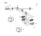
- FIG. 1 is a diagram illustrating a power supply and demand management system according to the first embodiment.
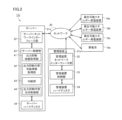
- FIG. 2 is a block diagram showing a configuration of a part of the power supply and demand management system shown in FIG.
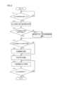
- FIG. 3 is a flowchart showing a process flow when managing the supply and demand of electricity in a power transmission and distribution area using the electricity supply and demand management system in the first embodiment.
- FIG. 4 is a diagram showing a state in which output suppression information has been transmitted.
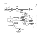
- FIG. 5 is a diagram showing a state in which output suppression information is transmitted in the power supply and demand management system in the second embodiment.
- the power supply and demand management system is a power supply and demand management system that includes a first power generation facility capable of stably supplying power within a power transmission and distribution area, a second power generation facility capable of generating power using renewable energy and supplying the power within the power transmission and distribution area, an alternative mechanism that substitutes for the output suppression of the power generated by the second power generation facility, and a server that controls the supply and demand of power by the second power generation facility and the alternative mechanism, and manages the supply and demand of power within the power transmission and distribution area.
- the server includes an output suppression information acquisition unit that acquires output suppression information for the second power generation equipment including information on output suppression time periods and information on output suppression amount to the second power generation equipment; an output suppression substitutable information acquisition unit that acquires output suppression substitutable information including information on time periods when the output suppression of power can be substituted by an alternative mechanism and information on the amount of power that can be substituted for the output suppression; a judgment unit that judges whether the entire amount of output suppression amount can be substituted for output suppression by the alternative mechanism based on the output suppression information acquired by the output suppression information acquisition unit and the output suppression substitutable information acquired by the output suppression substitutable information acquisition unit; and an output suppression substitutable status control unit that controls the substituting status of output suppression of power output from the second power generation equipment by the alternative mechanism in accordance with the judgment result by the judgment unit.
- the server acquires output suppression information for the second power generation equipment, which is a power generation equipment using renewable energy, including information on the time period during which output suppression to the second power generation equipment is performed and information on the amount of output suppression, and acquires output suppression substitutable information for the substituting mechanism that substitutes for the output suppression of the power generated by the second power generation equipment, including information on the time period during which the substituting mechanism can substitute for the output suppression of the power and information on the amount of power that can substitute for the output suppression. Then, based on the acquired output suppression information and the acquired output suppression substitutable information, it is determined whether the entire amount of the output suppression amount can be substituted for the output suppression by the substituting mechanism.
- the output suppression substituting status control unit controls the substituting status of the output suppression of the power output from the second power generation equipment by the substituting mechanism according to the judgment result, so that the power generated by the second power generation equipment can be efficiently used by utilizing the substitution of the output suppression by the substituting mechanism. Therefore, according to such a power supply and demand management system, power generation using renewable energy can be efficiently used.
- a plurality of second power generation facilities may be provided. If the determination unit does not determine that the entire amount of output suppression can be substituted for output suppression by the alternative mechanism, the output suppression substitution status control unit may control to suppress the output of any of the plurality of second power generation facilities according to a predetermined priority. In this way, when a plurality of second power generation facilities are provided, it is possible to make more effective use of the second power generation facilities in line with the needs of the power transmission and distribution business operator.
- the priority may be determined based on at least one of the following: information on the fee for using the alternative mechanism, location information of the second power generation facility, location information of the alternative mechanism, information on the stability of the voltage of the electricity transmission and distribution network, and information on the stability of the frequency of the electricity transmission and distribution network.
- information on the fee for using the alternative mechanism location information of the second power generation facility, location information of the alternative mechanism, information on the stability of the voltage of the electricity transmission and distribution network, and information on the stability of the frequency of the electricity transmission and distribution network.
- multiple alternative mechanisms may be provided. If the determination unit determines that the entire amount of output suppression can be substituted for output suppression by an alternative mechanism, the output suppression alternative status control unit may select one of the multiple alternative mechanisms and control it to substitute for the output suppression. In this way, when multiple alternative mechanisms are provided, it is possible to make effective use of the second power generation facility in line with the needs of the power transmission and distribution business operator.
- the alternative mechanism may include at least one of a storage battery, a fuel cell, a natural refrigerant heat pump water heater, and an adjustment of operation time of electrical equipment including production equipment.
- Such an alternative mechanism is a valid output destination of the electricity generated by the second power generation equipment.
- adjustment of operation time of electrical equipment including production equipment refers to, for example, adjusting the operation time of electrical equipment including production equipment to change the operation schedule of the electrical equipment including production equipment from late night to daytime when it is determined that the amount of electricity generated by renewable energy will be higher during the daytime, when the electrical equipment including production equipment is scheduled to operate during late night hours when electricity rates are cheaper than during the daytime.
- the output suppression alternative information acquisition unit may derive the amount of electricity that can be substituted for output suppression using at least one of the operation pattern, charging rate, temperature, degree of deterioration, and response record. In this way, efficient output suppression alternatives can be performed according to the usage status and environment of the alternative mechanism.
- the output suppression information acquisition unit may acquire the output suppression information by having the server receive the output suppression information transmitted from an external source. In this way, accurate and timely output suppression information transmitted from an external source can be effectively utilized to effectively utilize power generation using renewable energy.
- the output curtailment information acquisition unit may acquire output curtailment information by deriving output curtailment information using the upper capacity limit in the electricity transmission and distribution area, the predicted power generation amount in the second power generation facility, and the predicted power demand amount in the electricity transmission and distribution area. In this way, it is possible to control the alternative output curtailment situation using the derived output curtailment information without obtaining output curtailment information from outside.
- the output suppression alternative status control unit may use an alternative mechanism located outside the electricity transmission and distribution area to control the alternative status of output suppression of the electricity output from the second power generation equipment. In this way, it is possible to effectively utilize renewable energy by using equipment outside the electricity transmission and distribution area.
- the power supply and demand management method is a power supply and demand management method used in a power supply and demand management system that manages the supply and demand of power within a power transmission and distribution area, the system comprising a first power generation facility capable of stably supplying power within a power transmission and distribution area, a second power generation facility capable of generating power using renewable energy and supplying power within the power transmission and distribution area, an alternative mechanism that substitutes for the output suppression of power generated by the second power generation facility, and a server that controls the supply and demand of power by the second power generation facility and the alternative mechanism.
- the power supply and demand management method comprises the steps of acquiring output suppression information for the second power generation facility, including information on the time period during which the output suppression of power can be substituted by the alternative mechanism, and acquiring output suppression substitutable information, including information on the time period during which the alternative mechanism can substitute for the output suppression of power and information on the amount of power that can be substituted for the output suppression, determining whether the entire amount of output suppression can be substituted by the alternative mechanism based on the acquired output suppression information and the acquired output suppression substitutable information, and controlling the alternative state of the output suppression of power output from the second power generation facility by the alternative mechanism according to the determination result.
- This type of electricity supply and demand management method allows for efficient use of electricity generated using renewable energy.
- the program for an electricity supply and demand management system comprises a first power generation facility capable of stably supplying electricity within a power transmission and distribution area, a second power generation facility capable of generating electricity using renewable energy and supplying electricity within the power transmission and distribution area, an alternative mechanism that substitutes for the output suppression of electricity generated by the second power generation facility, and a server that controls the supply and demand of electricity by the second power generation facility and the alternative mechanism, and is a program for an electricity supply and demand management system that manages the supply and demand of electricity within a power transmission and distribution area, the server comprising an output suppression information acquisition unit that acquires output suppression information for the second power generation facility, including information on the time period during which output is suppressed and the amount of output suppression, and an output suppression information acquisition unit that acquires output suppression information for the second power generation facility, including information on the time period during which output is suppressed and the amount of output suppression, a power suppression substitutable information acquisition unit that acquires output suppression substitutable information including information on time periods when the substitution of the output suppression of power by the
- This type of program for an electricity supply and demand management system allows for efficient use of electricity generated using renewable energy sources.
- the storage medium disclosed herein is a computer-readable recording medium used in an electricity supply and demand management system that manages the supply and demand of electricity within a transmission and distribution area, the storage medium comprising: a first power generation facility capable of stably supplying electricity within a transmission and distribution area; a second power generation facility that generates electricity using renewable energy and is capable of supplying electricity within the transmission and distribution area; an alternative mechanism that substitutes for the output suppression of electricity generated by the second power generation facility; and a server that controls the supply and demand of electricity by the second power generation facility and the alternative mechanism, the server being an output suppression information acquisition unit that acquires output suppression information for the second power generation facility, including information on the time period during which output is suppressed and the amount of output suppression for the second power generation facility; a power suppression substitutable information acquisition unit that acquires output suppression substitutable information including information on time periods when substitution is possible and information on the amount of power that can be substituted for output suppression; a judgment unit that judges whether the entire amount of output suppression can be substituted for output suppression by the substituting mechanism
- Such a storage medium allows for efficient use of power generation using renewable energy.
- FIG. 1 is a diagram illustrating a schematic diagram of the power supply and demand management system according to the first embodiment.
- Fig. 2 is a block diagram illustrating a configuration of a part of the power supply and demand management system illustrated in Fig. 1.
- the power supply and demand management system 10a in the first embodiment manages the supply and demand of power within the power transmission and distribution area 11a under the jurisdiction of the power transmission and distribution business operator.
- the power supply and demand management system 10a includes a server 21a that manages the supply and demand of power for power supply and demand facilities arranged within the power transmission and distribution area 11a, specifically, renewable energy power generation facilities 16a, 16b, and 16c, stores 17a, houses 18a, and storage batteries 19a, which will be described later.
- the storage batteries 19a include lithium-ion batteries and NAS batteries (sodium-sulfur batteries). From the viewpoint of having a large capacity for efficient replacement and being able to efficiently charge and discharge for a long period of time, NAS batteries, which are suitable for industrial use, may be adopted as the storage batteries 19a.
- electricity is transmitted from a power plant 12a, which is a first power generation facility located outside the power transmission and distribution area 11a, via multiple transmission lines 13a, 13b, 13c, and 13d, and via multiple substations 14a and 14b to a distribution substation 14c.
- the power plant 12a is, for example, a thermal power plant, and is a power generation facility that can stably supply a constant amount of power within the power transmission and distribution area 11a. Electricity transformed by the distribution substation 14c is supplied to the power transmission and distribution area 11a via substations 14a and 14b.
- the power transmission and distribution area 11a stores 17a and houses 18a that consume electricity are located.
- the electricity transmitted to the power transmission and distribution area 11a is distributed to the stores 17a and houses 18a by the power distribution lines 15e and 15f, respectively.
- renewable energy power generation equipment 16a In addition, in the power transmission and distribution area 11a, renewable energy power generation equipment 16a, renewable energy power generation equipment 16b, and renewable energy power generation equipment 16c, which are second power generation equipment using renewable energy, are arranged. In this embodiment, a plurality of second power generation equipment are provided.
- the renewable energy power generation equipment 16a is a second power generation equipment that generates electricity using sunlight, which is renewable energy, and can supply electrodes within the power transmission and distribution area 11a.
- the amount of electricity generated by the renewable energy power generation equipment 16a depends on the hours of sunlight and the weather. In other words, the renewable energy power generation equipment 16a is a power generation equipment with an unstable supply of electricity.
- the renewable energy power generation equipment 16b and the renewable energy power generation equipment 16c have the same configuration as the renewable energy power generation equipment 16a.
- the electricity generated by the renewable energy power generation equipment 16a, the renewable energy power generation equipment 16b, and the renewable energy power generation equipment 16c is distributed to the store 17a and the house 18a by the distribution line 15b, the distribution line 15c, and the distribution line 15d, respectively.
- the distribution of electricity is controlled, for example, by a management device 31a owned by the electricity transmission and distribution company.
- the distribution lines 15b, 15c, 15d, 15e, 15f, and the distribution line 15g described below are each connected to the distribution line 15a that is connected to the distribution substation 14c.
- the renewable energy power generation facility 16a is not limited to power generation using solar light, and may be a wind power generation facility that uses wind power as renewable energy, or a biomass power generation facility that uses biomass as renewable energy.
- alternative facilities such as a storage battery 19a that stores electricity are arranged as an alternative mechanism for suppressing the output of electricity generated by the second power generation facilities, namely, the renewable energy power generation facilities 16a, 16b, and 16c.
- the storage battery 19a is connected to the power distribution line 15g, and can store electricity distributed from the power distribution line 15g according to the storage capacity of the storage battery 19a.
- the electricity stored by the storage battery 19a is supplied to the stores 17a and houses 18a under the control of a management device 31a owned by the power transmission and distribution company.
- the management device 31a is communicatively connected to the renewable energy power generation facilities 16a, 16b, 16c, and the storage battery 19a via the network 20.
- the network 20 may be the Internet, or an internal network in a closed environment constructed for the power transmission and distribution area 11a, such as an intranet.
- the network 20 may be wired or wireless.
- the management device 31a includes a management device network interface unit 32 for connecting to the network 20, a management device control unit 33 for controlling the management device 31a itself, and a management device hard disk 34 as a storage unit for storing data.
- a display for displaying data, and a keyboard and mouse for inputting data are connected to the management device 31a, which serve as the interface of the management device 31a.
- the server 21a controls the supply and demand of electricity within the power transmission and distribution area 11a. Specifically, the server 21a controls the output of the renewable energy power generation equipment 16a, the renewable energy power generation equipment 16b, and the renewable energy power generation equipment 16c, which are the second power generation equipment, and the alternative output suppression by the storage battery 19a, which is the alternative mechanism. As with the management device 31a, the server 21a is communicatively connected to the renewable energy power generation equipment 16a, the renewable energy power generation equipment 16b, the renewable energy power generation equipment 16c, and the storage battery 19a via the network 20.
- the server 21a includes a server network interface unit 22 for connecting to the network 20, a server control unit 23 for controlling the server 21a itself, and a server hard disk 24 as a storage unit for storing data.
- a display for displaying data, and a keyboard and mouse for inputting data are connected to the server 21a, which serve as the interface of the server 21a.
- the server control unit 23 includes an output suppression information acquisition unit 41, an output suppression substitutable information acquisition unit 42, a judgment unit 43, and an output suppression substitutable status control unit 44.
- the output suppression information acquisition unit 41 acquires output suppression information for the second power generation equipment, including information on output suppression time periods and output suppression amounts for the renewable energy power generation equipment 16a, the renewable energy power generation equipment 16b, and the renewable energy power generation equipment 16c, which are the second power generation equipment.
- the output suppression substitutable information acquisition unit 42 acquires output suppression substitutable information, including information on time periods when the output suppression of power can be substituted by the storage battery 19a, which is the substituting mechanism, and information on the amount of power that can be substituted for the output suppression.
- the judgment unit 43 judges whether the entire amount of output suppression amount can be substituted for the output suppression by the storage battery 19a, which is the substituting mechanism, based on the output suppression information acquired by the output suppression information acquisition unit 41 and the output suppression substitutable information acquired by the output suppression substitutable information acquisition unit 42.
- the output suppression alternative status control unit 44 controls the alternative status of the output suppression of the power output from the second power generation equipment by the storage battery 19a, which is an alternative mechanism, according to the result of the judgment by the judgment unit 43. The configuration of each unit will be described in detail later.
- the power supply and demand management system 10a adds together the stable amount of power supplied from the power plant 12a such as a thermal power plant and the power generated by the renewable energy power generation equipment 16a, the renewable energy power generation equipment 16b, and the renewable energy power generation equipment 16c, and distributes the power to stores and houses that consume the power using the power transmission and distribution network.
- the amount of power generated by the renewable energy power generation equipment 16a, etc. becomes larger than expected due to longer sunshine hours, etc., and is likely to exceed the upper limit of the power that can be transmitted by the power transmission and distribution network, it is necessary to suppress the output of power generated using renewable energy.
- the power supply and demand management system 10a of the present disclosure it is possible to substitute for output suppression.
- the power supply and demand management system 10a of the present disclosure the surplus power generated by the renewable energy power generation equipment 16a, etc., which has previously been subjected to output suppression, is absorbed and effectively used in multiple electrical equipment and production equipment. This will be described below.
- Figure 3 is a flowchart showing the process flow when managing the power supply and demand in the power transmission and distribution area 11a using the power supply and demand management system 10a in embodiment 1.
- server 21a manages the balance of supply and demand of electricity within transmission and distribution area 11a.
- server 21a manages the balance by monitoring in real time the output state of renewable energy power generation equipment 16a, renewable energy power generation equipment 16b, and renewable energy power generation equipment 16c, which are second power generation equipment in transmission and distribution area 11a, the power consumption state in stores 17a and houses 18a, the power storage state in storage battery 19a, etc.
- the management device 31a that manages these renewable energy power generation equipment 16a and the renewable energy power generation equipment 16b transmits output suppression information to the renewable energy power generation equipment 16a and the renewable energy power generation equipment 16b.
- Figure 4 is a diagram showing the state in which the output suppression information has been transmitted. In this case, as shown in Figure 4, an output suppression signal is transmitted from the management device 31a located outside the power transmission and distribution area 11a to the renewable energy power generation equipment 16a and the renewable energy power generation equipment 16b.
- an output suppression signal is transmitted from the renewable energy power generation equipment 16a and the renewable energy power generation equipment 16b to the server 21a.
- the output suppression information acquisition unit 41 acquires output suppression signals from the renewable energy power generation equipment 16a and the renewable energy power generation equipment 16b (YES in step S11 in FIG. 3, hereinafter, "step” will be omitted). That is, the output suppression information acquisition unit 41 acquires output suppression information by the server 21a receiving output suppression information transmitted from the outside. In this case, the output suppression information acquisition unit 41 acquires output suppression information by receiving an output suppression signal using the network 20.
- the output suppression information includes information on the output suppression time period and information on the output suppression amount. That is, the output suppression information acquisition unit 41 acquires output suppression information including information on the output suppression time period and information on the output suppression amount.
- the output suppression substitutable information acquisition unit 42 acquires output suppression substitutable information from the storage battery 19a, which is the substituting mechanism (S12).
- the output suppression substitutable information from the storage battery 19a includes information on the time period during which the storage battery 19a can substitute for the power output suppression and information on the amount of power that can substitute for the output suppression.
- the output suppression substitutable information acquisition unit 42 acquires output suppression substitutable information including information on the time period during which the storage battery 19a can store electricity and the amount of electricity that can be stored.
- the server 21a acquires the electricity storage information from the storage battery 19a in real time, and therefore acquires the output suppression substitutable information from this electricity storage information.
- the determination unit 43 determines whether the entire amount of output suppression can be substituted by the substitution mechanism based on the output suppression information acquired by the output suppression information acquisition unit 41 and the output suppression substitutability information acquired by the output suppression substitutability information acquisition unit 42 (S13). That is, it determines whether the amount of output suppression during the output suppression time period when output suppression is issued by the renewable energy power generation equipment 16a and the renewable energy power generation equipment 16b is an amount that can be substituted by the storage battery 19a during the output suppression time period.
- the output suppression substitution status control unit 44 controls the substitution status of the output suppression of the power output from the renewable energy power generation equipment 16a and the renewable energy power generation equipment 16b, which are the second power generation equipment by the substitution mechanism, according to the judgment result by the judgment unit 43. Specifically, the following processing is performed. If the judgment unit 43 does not judge that the entire amount of output suppression during the time period of output suppression is substitutable (NO in S13), one of the multiple second power generation equipment is selected according to a predetermined priority (S14). Specifically, for example, one of the renewable energy power generation equipment 16a and the renewable energy power generation equipment 16b is selected.
- the output suppression substitution status control unit 44 determines whether the output suppression amount is equal to or less than the output suppression substitution amount (S15). This process is also performed when one of the second power generation facilities is selected in S14.
- output control of the substitution mechanism is performed (S18). That is, control is performed so that the power output by the renewable energy power generation equipment 16a and the renewable energy power generation equipment 16b is stored in the storage battery 19a. This is performed until the output suppression time ends (S19). This control is performed while acquiring data in real time so that the amount of output suppression and the amount of output suppression substitution are equal. Note that confirmation and proof that such substitution of output suppression by the substitution mechanism is being reliably performed may be managed by tagging using blockchain.
- the server 21a acquires output suppression information for the second power generation equipment, such as the renewable energy power generation equipment 16a, which is the second power generation equipment that generates electricity using renewable energy, including information on the time period during which output suppression to the second power generation equipment is performed and information on the amount of output suppression, and acquires output suppression substitution possibility information for the storage battery 19a, which is an alternative mechanism that substitutes for the output suppression of electricity generated by the second power generation equipment, including information on the time period during which the alternative mechanism can substitute for the output suppression of electricity and information on the amount of electricity that can substitute for the output suppression.
- the renewable energy power generation equipment 16a which is the second power generation equipment that generates electricity using renewable energy
- the storage battery 19a which is an alternative mechanism that substitutes for the output suppression of electricity generated by the second power generation equipment, including information on the time period during which the alternative mechanism can substitute for the output suppression of electricity and information on the amount of electricity that can substitute for the output suppression.
- the output suppression substitution status control unit 44 controls the substitution status of the output suppression of electricity output from the second power generation equipment by the alternative mechanism according to the judgment result, so that the electricity generated by the second power generation equipment can be efficiently used by utilizing the substitution of output suppression by the alternative mechanism. Therefore, according to such a power supply and demand management system 10a, power generation using renewable energy can be efficiently used.
- a plurality of second power generation facilities such as renewable energy power generation facilities 16a. If the determination unit 43 does not determine that the entire amount of output suppression can be substituted by the substitution mechanism, the output suppression substitution status control unit 44 controls to substitute the output of one of the plurality of second power generation facilities according to a predetermined priority. Therefore, when a plurality of second power generation facilities are provided, it is possible to effectively utilize the second power generation facilities in accordance with the needs of the electricity transmission and distribution business operator.
- the output suppression information acquisition unit 41 acquires the output suppression information by having the server 21a receive the output suppression information transmitted from the outside. Therefore, it is possible to effectively utilize power generation using renewable energy by effectively utilizing accurate and timely output suppression information transmitted from the outside.
- the priority may be determined based on at least one of the following: information on the fee for using the alternative mechanism, location information of the second power generation facility, location information of the alternative mechanism, information on the stability of the voltage of the power transmission and distribution network, and information on the stability of the frequency of the power transmission and distribution network. In this way, power generation using renewable energy can be more effectively utilized based on the location information of the second power generation facility, etc.
- a plurality of alternative mechanisms may be provided. If the determination unit 43 determines that the entire amount of output suppression can be substituted for output suppression by an alternative mechanism, the output suppression alternative status control unit 44 may select one of the plurality of alternative mechanisms and control it to substitute for the output suppression. In this way, when a plurality of alternative mechanisms are provided, it is possible to effectively utilize the second power generation equipment in line with the needs of the power transmission and distribution business operator.
- the alternative mechanism may include at least one of a storage battery, a fuel cell, a natural refrigerant heat pump water heater, and an adjustment of the operating time of electrical equipment including production equipment.
- Such an alternative mechanism is an effective output destination of the power generated by the second power generation equipment.
- the output command is distributed in consideration of the required output suppression amount, for example, the state (SOC (State of Charge), temperature, degree of deterioration, etc.) of the alternative equipment that is the selected alternative mechanism, the response time, and the response record.
- the response record of each alternative equipment is collected in this system, and it is monitored whether there is a difference with respect to the required output suppression amount.
- the output command value may be changed or the alternative equipment that is the command destination may be reselected.
- actual data of the power transmission and distribution equipment may be obtained, and the required output suppression amount may be recalculated from the limitations of the power transmission and distribution equipment.
- the output suppression alternative status control unit 44 may use an alternative mechanism located outside the power transmission and distribution area to control the alternative status of output suppression of the power output from the second power generation equipment. In this way, it is possible to effectively utilize renewable energy by using equipment outside the power transmission and distribution area.
- the output of the power stored in the storage battery is controlled as follows. First, the capacity limit value of the power transmission and distribution area is confirmed, and then it is determined whether or not there is a limit due to the output. If there is no limit, output is started. On the other hand, if there is a limit, it is determined whether or not there is an exchange of power in another power transmission and distribution area. If there is an exchange of power, a prediction of power consumption in the power transmission and distribution area of the exchange destination is made, and the desired exchange amount is confirmed.
- FIG. 5 is a diagram showing a state in which output suppression information is transmitted in a power supply and demand management system in embodiment 2.
- the power supply and demand management system in embodiment 2 basically has the same configuration as in embodiment 1, and achieves the same effects. However, the power supply management system in embodiment 2 differs from embodiment 1 in the destination of the output suppression information transmitted from the management device 31a and the subsequent processing flow.
- the output suppression signal is not transmitted from the management device 31a to the renewable energy power generation facility 16a and the renewable energy power generation facility 16b as in the first embodiment, but is transmitted directly from the management device 31a to the server 21a as shown by the arrow D1 .
- This output suppression signal includes output suppression information.
- the server 21a obtains the output suppression information shown in S11 from the management device 31a (S12).
- the output suppression information includes, for example, information on the time period during which the output is suppressed and the suppression amount of the output.
- the server 21a grasps the acquired output suppression information and the alternative mechanism, specifically, for example, the state of the storage battery 19a, and responds to the management device 31a with output substitution possible information, such as the time period and amount of substitution possible, as indicated by the arrow D2 . Then, the management device 31a transmits an output suppression signal to the renewable energy power generation equipment 16a and the renewable energy power generation equipment 16b based on the response information. The management device 31a also requests the server 21a to substitute for the output suppression. The server 21a performs subsequent processing according to the content of the request. Such a configuration may be adopted.
- the server 21a may also acquire output suppression information from the renewable energy power generation equipment 16a, etc.
- the output suppression information may include the target power plant and the above-mentioned priority.
- the priority of the equipment that performs alternative output may be determined by the management device 31a, or may be determined by the server 21a in the same manner as in the other embodiments, depending on the location information, frequency information, and compensation information.
- the output suppression information acquisition unit acquires the output suppression information by having the server receive the output suppression information transmitted from the outside, but this is not limited to this. That is, the output suppression information acquisition unit may acquire the output suppression information by deriving the output suppression information using the upper limit value of the capacity in the power transmission and distribution area, the predicted value of the power generation amount in the second power generation facility, and the predicted value of the power demand amount in the power transmission and distribution area. Specifically, if the difference obtained by subtracting the predicted value of the power demand in the power transmission and distribution area from the predicted value of the power generation amount in the second power generation facility is greater than the upper limit value of the capacity in the power transmission and distribution area, it is determined that the output request information has been acquired. In this way, it is possible to control the alternative situation of output suppression by using the derived output suppression information without obtaining the output suppression information from the outside.
- the power supply and demand management method is a power supply and demand management method used in a power supply and demand management system that manages the supply and demand of power within a power transmission and distribution area, the system comprising a first power generation facility capable of stably supplying power within a power transmission and distribution area, a second power generation facility capable of generating power using renewable energy and supplying power within the power transmission and distribution area, an alternative mechanism that substitutes for the output suppression of power generated by the second power generation facility, and a server that controls the supply and demand of power by the second power generation facility and the alternative mechanism.
- the power supply and demand management method comprises the steps of acquiring output suppression information for the second power generation facility, including information on the time period during which the output suppression of power can be substituted by the alternative mechanism, and acquiring output suppression substitutable information, including information on the time period during which the alternative mechanism can substitute for the output suppression of power and information on the amount of power that can be substituted for the output suppression, determining whether the entire amount of output suppression can be substituted by the alternative mechanism based on the acquired output suppression information and the acquired output suppression substitutable information, and controlling the alternative state of the output suppression of power output from the second power generation facility by the alternative mechanism according to the determination result.
- This type of electricity supply and demand management method allows for efficient use of electricity generated using renewable energy.
- the program for an electricity supply and demand management system is a program for an electricity supply and demand management system that manages the supply and demand of electricity within a power transmission and distribution area, the program comprising: a first power generation facility capable of stably supplying electricity within a power transmission and distribution area; a second power generation facility that generates electricity using renewable energy and is capable of supplying electricity within the power transmission and distribution area; an alternative mechanism that substitutes for the output suppression of electricity generated by the second power generation facility; and a server that controls the supply and demand of electricity by the second power generation facility and the alternative mechanism, the program comprising: an output suppression mechanism that substitutes for the ...
- a suppression information acquisition unit an output suppression substitutable information acquisition unit that acquires output suppression substitutable information including information on time periods when the alternative mechanism can substitute for the suppression of power output and information on the amount of power that can be substituted for the suppression of power output; a judgment unit that judges whether the entire amount of output suppression can be substituted for the suppression of power output by the alternative mechanism based on the output suppression information acquired by the output suppression information acquisition unit and the output suppression substitutable information acquired by the output suppression substitutable information acquisition unit; and an output suppression substitutable status control unit that controls the substituting status of the suppression of power output from the second power generation facility by the alternative mechanism according to the judgment result by the judgment unit.
- This type of program for an electricity supply and demand management system allows for efficient use of electricity generated using renewable energy sources.
- the storage medium disclosed herein is a computer-readable recording medium used in an electricity supply and demand management system that manages the supply and demand of electricity within a transmission and distribution area, the storage medium comprising: a first power generation facility capable of stably supplying electricity within a transmission and distribution area; a second power generation facility that generates electricity using renewable energy and is capable of supplying electricity within the transmission and distribution area; an alternative mechanism that substitutes for the output suppression of electricity generated by the second power generation facility; and a server that controls the supply and demand of electricity by the second power generation facility and the alternative mechanism, the server being an output suppression information acquisition unit that acquires output suppression information for the second power generation facility, including information on the time period during which output is suppressed and the amount of output suppression for the second power generation facility; a power suppression substitutable information acquisition unit that acquires output suppression substitutable information including information on time periods when substitution is possible and information on the amount of power that can be substituted for output suppression; a judgment unit that judges whether the entire amount of output suppression can be substituted for output suppression by the substituting mechanism
- Such a storage medium allows for efficient use of power generation using renewable energy.
- 10a, 10b power supply and demand management system
- 11a power transmission and distribution area
- 12a power plant
- 13e power transmission lines
- 14a, 14b substations
- 14c power distribution substations.
- 15a, 15b, 15c, 15d, 15e, 15f, 15g power distribution lines
- 16a, 16b, 16c renewable energy power generation facilities
- 17a stores
- 18a houses
Landscapes
- Engineering & Computer Science (AREA)
- Power Engineering (AREA)
- Supply And Distribution Of Alternating Current (AREA)
- Remote Monitoring And Control Of Power-Distribution Networks (AREA)
- Charge And Discharge Circuits For Batteries Or The Like (AREA)
Abstract
電力需給管理システムは、第1発電設備と、再生可能エネルギーを利用して発電する第2発電設備と、第2発電設備により発電された電力の出力抑制の代替を行う代替機構と、サーバーと、を備える。サーバーは、第2発電設備への出力抑制時間帯の情報および出力抑制量の情報を含む第2発電設備への出力抑制情報を取得する出力抑制情報取得部と、代替機構による電力の出力抑制の代替が可能な時間帯の情報および出力抑制の代替が可能な電力量の情報を含む出力抑制代替可能情報を取得する出力抑制代替可能情報取得部と、出力抑制情報および出力抑制代替可能情報に基づいて、出力抑制量の全量が代替機構による出力抑制の代替が可能であるか否かを判断する判断部と、判断部による判断結果に応じて、代替機構による第2発電設備から出力された電力の出力抑制の代替状況を制御する出力抑制代替状況制御部と、を備える。
Description
本開示は、電力需給管理システム、電力需給管理方法、電力需給管理プログラムおよび記録媒体に関するものである。
太陽光や風力等の再生可能エネルギーを利用して発電された余剰電力を蓄電池に充電する発電システムが知られている(例えば、特許文献1参照)。また、複数の蓄電池を準備し、いずれの蓄電池に充電させるかを決定するシステムに関する技術が知られている(例えば、特許文献2、特許文献3および特許文献4参照)。
火力発電所等の発電所によって発電された電力は、送電事業および配電事業を行う送配電事業者によって家庭や店舗、工場といった需要者に供給される。昨今において、太陽光や風力といった再生可能エネルギーを利用して発電された電力が有効に利用される。再生可能エネルギーを利用した電力については、例えば、季節や時間、天候といった要因に起因して発電量が変化することも多く、発電量の制御が困難である。現在、安定した電力量を供給できる火力発電所等により発電された電力と、再生可能エネルギーを利用した発電による電力とを足し合わせて、需要者への電力の供給がなされている。
安定した電力供給を行うに際し、再生可能エネルギーを利用した発電による電力量が想定よりも大きくなり、送配電網の送電可能な上限量を超えそうな場合においては、再生可能エネルギーを利用した発電による電力の出力を抑制する必要がある。このような状況は、再生可能エネルギーを利用した発電が可能な状況にもかかわらず制限をかけることになり、好ましくない。再生可能エネルギーを利用した発電を有効利用しようと画策し、再生可能エネルギーを利用した発電の電力の最大値を考慮した設備を構築しようとすると、増強工事等が必要となり、発電事業者や小売事業者ひいては需要者の負担が大きくなる。送配電事業者の収益性を悪化させることになりかねない。
そこで、再生可能エネルギーを利用した発電を効率的に利用することができる電力需給管理システムを提供することを本開示の目的の1つとする。
本開示に従った電力需給管理システムは、送配電エリア内に安定して電力を供給可能な第1発電設備と、再生可能エネルギーを利用して発電し、送配電エリア内に電力を供給可能な第2発電設備と、第2発電設備により発電された電力の出力抑制の代替を行う代替機構と、第2発電設備および代替機構による電力の需給を制御するサーバーと、を備え、送配電エリア内の電力の需給を管理する電力需給管理システムである。サーバーは、第2発電設備への出力抑制時間帯の情報および出力抑制量の情報を含む第2発電設備への出力抑制情報を取得する出力抑制情報取得部と、代替機構による電力の出力抑制の代替が可能な時間帯の情報および出力抑制の代替可能な電力量の情報を含む出力抑制の代替可能情報を取得する出力抑制代替可能情報取得部と、出力抑制情報取得部により取得された出力抑制情報および出力抑制代替可能情報取得部により取得された出力抑制の代替可能情報に基づいて、出力抑制量の全量が代替機構による出力抑制の代替が可能であるか否かを判断する判断部と、判断部による判断結果に応じて、代替機構による第2発電設備から出力された電力の出力抑制の代替状況を制御する出力抑制代替状況制御部と、を備える。
上記電力需給管理システムによれば、再生可能エネルギーを利用した発電を効率的に利用することができる。
[本開示の実施形態の説明]
最初に本開示の実施態様を列記して説明する。本開示に係る電力需給管理システムは、電力需給管理システムは、送配電エリア内に安定して電力を供給可能な第1発電設備と、再生可能エネルギーを利用して発電し、送配電エリア内に電力を供給可能な第2発電設備と、第2発電設備により発電された電力の出力抑制の代替を行う代替機構と、第2発電設備および代替機構による電力の需給を制御するサーバーと、を備え、送配電エリア内の電力の需給を管理する電力需給管理システムである。サーバーは、第2発電設備への出力抑制時間帯の情報および出力抑制量の情報を含む第2発電設備への出力抑制情報を取得する出力抑制情報取得部と、代替機構による電力の出力抑制の代替が可能な時間帯の情報および出力抑制の代替可能な電力量の情報を含む出力抑制の代替可能情報を取得する出力抑制代替可能情報取得部と、出力抑制情報取得部により取得された出力抑制情報および出力抑制代替可能情報取得部により取得された出力抑制の代替可能情報に基づいて、出力抑制量の全量が代替機構による出力抑制の代替が可能であるか否かを判断する判断部と、判断部による判断結果に応じて、代替機構による第2発電設備から出力された電力の出力抑制の代替状況を制御する出力抑制代替状況制御部と、を備える。
最初に本開示の実施態様を列記して説明する。本開示に係る電力需給管理システムは、電力需給管理システムは、送配電エリア内に安定して電力を供給可能な第1発電設備と、再生可能エネルギーを利用して発電し、送配電エリア内に電力を供給可能な第2発電設備と、第2発電設備により発電された電力の出力抑制の代替を行う代替機構と、第2発電設備および代替機構による電力の需給を制御するサーバーと、を備え、送配電エリア内の電力の需給を管理する電力需給管理システムである。サーバーは、第2発電設備への出力抑制時間帯の情報および出力抑制量の情報を含む第2発電設備への出力抑制情報を取得する出力抑制情報取得部と、代替機構による電力の出力抑制の代替が可能な時間帯の情報および出力抑制の代替可能な電力量の情報を含む出力抑制の代替可能情報を取得する出力抑制代替可能情報取得部と、出力抑制情報取得部により取得された出力抑制情報および出力抑制代替可能情報取得部により取得された出力抑制の代替可能情報に基づいて、出力抑制量の全量が代替機構による出力抑制の代替が可能であるか否かを判断する判断部と、判断部による判断結果に応じて、代替機構による第2発電設備から出力された電力の出力抑制の代替状況を制御する出力抑制代替状況制御部と、を備える。
本開示における電力需給管理システムによると、サーバーは、再生可能エネルギーを利用した発電である第2発電設備について、第2発電設備への出力抑制時間帯の情報および出力抑制量の情報を含む第2発電設備への出力抑制情報を取得し、第2発電設備により発電された電力の出力抑制の代替を行う代替機構について、代替機構による電力の出力抑制の代替が可能な時間帯の情報および出力抑制の代替が可能な電力量の情報を含む出力抑制代替可能情報を取得する。そして、取得された出力抑制情報および取得された出力抑制代替可能情報に基づいて、出力抑制量の全量が代替機構による出力抑制の代替が可能であるか否かを判断する。出力抑制代替状況制御部は、判断結果に応じて代替機構による第2発電設備から出力された電力の出力抑制の代替状況を制御するため、代替機構による出力抑制の代替を利用して、第2発電設備により発電された電力を効率的に利用することができる。したがって、このような電力需給管理システムによると、再生可能エネルギーを利用した発電を効率的に利用することができる。
上記電力需給管理システムにおいて、第2発電設備は、複数設けられていてもよい。出力抑制代替状況制御部は、判断部により出力抑制量の全量が代替機構による出力抑制の代替が可能であると判断されなければ、予め定められた優先度に応じて複数の第2発電設備のうちのいずれかの出力を抑制するよう制御してもよい。このようにすることにより、複数の第2発電設備が設けられている場合において、より送配電事業者のニーズに沿った第2発電設備の有効利用を図ることができる。
上記電力需給管理システムにおいて、優先度は、代替機構を利用する際の料金の情報、第2発電設備の位置情報、代替機構の位置情報、送配電網の電圧の安定度合いの情報および送配電網の周波数の安定度合いの情報のうちの少なくともいずれか1つに基づいて定められてもよい。このようにすることにより、第2発電設備の位置情報等に基づいて、再生可能エネルギーを利用した発電をより効果的に利用することができる。
上記電力需給管理システムにおいて、代替機構は、複数設けられていてもよい。出力抑制代替状況制御部は、判断部により出力抑制量の全量が代替機構による出力抑制の代替が可能であると判断されれば、複数の代替機構のうちのいずれかを選択して出力抑制の代替をするよう制御してもよい。このようにすることにより、複数の代替機構が設けられている場合において、より送配電事業者のニーズに沿った第2発電設備の有効利用を図ることができる。
上記電力需給管理システムにおいて、代替機構は、蓄電池、燃料電池、自然冷媒ヒートポンプ給湯器および、生産設備を含む電気設備の稼働時間調整のうちの少なくともいずれか1つを含んでもよい。このような代替機構は、第2発電設備により発電された電力の有効な出力先となる。ここで、「生産設備を含む電気設備の稼働時間調整」とは、生産設備を含む電気設備について、例えば、電力の料金が昼間よりも安い深夜の時間帯に生産設備を含む電気設備を稼働させるよう予定されていた場合において、再生可能エネルギーによる発電の電力量が昼間に多くなると判断された場合に、深夜に稼働させようとしていた稼働の予定を変更して昼間に稼働させるように稼働時間を調整することをいう。
上記電力需給管理システムにおいて、出力抑制代替可能情報取得部は、代替機構が蓄電池または燃料電池であれば、運用パターン、充電率、温度、劣化度および応動実績のうちの少なくともいずれか1つを用いて出力抑制の代替が可能な電力量を導出してもよい。このようにすることにより、代替機構の使用状況や環境等に応じて、効率的な出力抑制の代替を行うことができる。
上記電力需給管理システムにおいて、出力抑制情報取得部は、外部から発信された出力抑制情報をサーバーが受信することにより出力抑制情報を取得してもよい。このようにすることにより、外部から発信された正確かつタイムリーな出力抑制情報を有効活用して、再生可能エネルギーを利用した発電を効果的に利用することができる。
上記電力需給管理システムにおいて、出力抑制情報取得部は、送配電エリアにおける容量の上限値、第2発電設備における発電量の予測値および送配電エリア内の電力の需要量の予測値を用いて出力抑制情報を導出することにより出力抑制情報を取得してもよい。このようにすることにより、外部からの出力抑制情報を入手しなくとも導出した出力抑制情報を利用して、出力抑制の代替状況を制御することができる。
上記電力需給管理システムにおいて、出力抑制代替状況制御部は、判断部により出力抑制量の全量が代替機構による出力抑制の代替が可能であると判断されなければ、送配電エリア外に配置される代替機構を利用して、第2発電設備から出力された電力の出力抑制の代替状況を制御してもよい。このようにすることにより、送配電エリア外の設備を利用して、再生可能エネルギーの有効活用を図ることができる。
本開示に係る電力需給管理方法は、送配電エリア内に安定して電力を供給可能な第1発電設備と、再生可能エネルギーを利用して発電し、送配電エリア内に電力を供給可能な第2発電設備と、第2発電設備により発電された電力の出力抑制の代替を行う代替機構と、第2発電設備および代替機構による電力の需給を制御するサーバーと、を備え、送配電エリア内の電力の需給を管理する電力需給管理システムに用いられる電力需給管理方法である。電力需給管理方法は、第2発電設備への出力抑制時間帯の情報および出力抑制量の情報を含む第2発電設備への出力抑制情報を取得する工程と、代替機構による電力の出力抑制の代替が可能な時間帯の情報および出力抑制の代替が可能な電力量の情報を含む出力抑制代替可能情報を取得する工程と、取得された出力抑制情報および取得された出力抑制代替可能情報に基づいて、出力抑制量の全量が代替機構による出力抑制の代替が可能であるか否かを判断する工程と、判断結果に応じて、代替機構による第2発電設備から出力された電力の出力抑制の代替状況を制御する工程と、を備える。
このような電力需給管理方法によれば、再生可能エネルギーを利用した発電を効率的に利用することができる。
本開示に係る電力需給管理システム用プログラムは、送配電エリア内に安定して電力を供給可能な第1発電設備と、再生可能エネルギーを利用して発電し、送配電エリア内に電力を供給可能な第2発電設備と、第2発電設備により発電された電力の出力抑制の代替を行う代替機構と、第2発電設備および代替機構による電力の需給を制御するサーバーと、を備え、送配電エリア内の電力の需給を管理する電力需給管理システム用プログラムであって、サーバーを、第2発電設備への出力抑制時間帯の情報および出力抑制量の情報を含む第2発電設備への出力抑制情報を取得する出力抑制情報取得部、代替機構による電力の出力抑制の代替が可能な時間帯の情報および出力抑制の代替が可能な電力量の情報を含む出力抑制代替可能情報を取得する出力抑制代替可能情報取得部、出力抑制情報取得部により取得された出力抑制情報および出力抑制代替可能情報取得部により取得された出力抑制代替可能情報に基づいて、出力抑制量の全量が代替機構による出力抑制の代替が可能であるか否かを判断する判断部、および判断部による判断結果に応じて、代替機構による第2発電設備から出力された電力の出力抑制の代替状況を制御する出力抑制代替状況制御部、として機能させるための電力需給管理システム用プログラムである。
このような電力需給管理システム用プログラムによれば、再生可能エネルギーを利用した発電を効率的に利用することができる。
本開示に係る記憶媒体は、送配電エリア内に安定して電力を供給可能な第1発電設備と、再生可能エネルギーを利用して発電し、送配電エリア内に電力を供給可能な第2発電設備と、第2発電設備により発電された電力の出力抑制の代替を行う代替機構と、第2発電設備および代替機構による電力の需給を制御するサーバーと、を備え、送配電エリア内の電力の需給を管理する電力需給管理システムに用いられ、コンピューター読み取り可能な記録媒体であって、サーバーを、第2発電設備への出力抑制時間帯の情報および出力抑制量の情報を含む第2発電設備への出力抑制情報を取得する出力抑制情報取得部、代替機構による電力の出力抑制の代替が可能な時間帯の情報および出力抑制の代替が可能な電力量の情報を含む出力抑制代替可能情報を取得する出力抑制代替可能情報取得部、出力抑制情報取得部により取得された出力抑制情報および出力抑制代替可能情報取得部により取得された出力抑制代替可能情報に基づいて、出力抑制量の全量が代替機構による出力抑制の代替が可能であるか否かを判断する判断部、および判断部による判断結果に応じて、代替機構による第2発電設備から出力された電力の出力抑制の代替状況を制御する出力抑制代替状況制御部、として機能させるための電力需給管理システム用プログラムを記録したコンピューター読み取り可能な記録媒体である。
このような記憶媒体によれば、再生可能エネルギーを利用した発電を効率的に利用することができる。
[本願発明の実施形態の詳細]
次に、本開示の電力需給管理システムを含む電力需給管理システムの一実施形態を、図面を参照しつつ説明する。以下の図面において同一または相当する部分には同一の参照符号を付しその説明は繰り返さない。
次に、本開示の電力需給管理システムを含む電力需給管理システムの一実施形態を、図面を参照しつつ説明する。以下の図面において同一または相当する部分には同一の参照符号を付しその説明は繰り返さない。
(実施の形態1)
本開示の実施の形態1における電力需給管理システムの構成について説明する。図1は、実施の形態1における電力需給管理システムを模式的に示す図である。図2は、図1に示す電力需給管理システムの一部の構成を示すブロック図である。
本開示の実施の形態1における電力需給管理システムの構成について説明する。図1は、実施の形態1における電力需給管理システムを模式的に示す図である。図2は、図1に示す電力需給管理システムの一部の構成を示すブロック図である。
図1および図2を参照して、実施の形態1における電力需給管理システム10aは、送配電事業者が管轄する送配電エリア11a内の電力の需給を管理する。電力需給管理システム10aは、送配電エリア11a内に配置される電力需給設備、具体的には、後述する再生可能エネルギー発電設備16a、再生可能エネルギー発電設備16b、再生可能エネルギー発電設備16c、店舗17a、家屋18aおよび蓄電池19aに関する電力の需給を管理するサーバー21aを含む。ここで、蓄電池19aとしては、例えば、リチウムイオン電池やNAS電池(ナトリウム・硫黄電池)が挙げられる。効率よく代替するために大容量という特徴を有する観点および長時間の充放電を効率よく行うことができる観点から、蓄電池19aとして産業用に好適に用いられるNAS電池を採用することにしてもよい。
送配電エリア11aには、送配電エリア11aの外部に配置された第1発電設備である発電所12aから複数の送電線13a、送電線13b、送電線13c、送電線13dを介し、複数の変電所14a、変電所14bを経由して、配電用変電所14cに送電される。発電所12aは、例えば火力発電所であり、安定して送配電エリア11a内に一定の電力を供給可能な発電設備である。送配電エリア11aには、変電所14a、変電所14bを経由して、配電用変電所14cにより変電された電力が供給される。
送配電エリア11a内には、電力を消費する店舗17aや家屋18aが配置されている。送配電エリア11a内に送電された電力は、配電線15e、配電線15fによって店舗17aや家屋18aにそれぞれ配電される。
また、送配電エリア11a内には、再生可能エネルギーを利用した第2発電設備である再生可能エネルギー発電設備16a、再生可能エネルギー発電設備16bおよび再生可能エネルギー発電設備16cが配置されている。本実施形態においては、第2発電設備は、複数設けられている。再生可能エネルギー発電設備16aは、再生可能エネルギーである太陽光を利用して発電し、送配電エリア11a内に電極を供給可能な第2発電設備である。再生可能エネルギー発電設備16aは、日照時間や天候等により発電量が左右される。すなわち、再生可能エネルギー発電設備16aは、電力の供給量が不安定な発電設備である。再生可能エネルギー発電設備16bおよび再生可能エネルギー発電設備16cについても再生可能エネルギー発電設備16aと同様の構成である。再生可能エネルギー発電設備16a、再生可能エネルギー発電設備16b、再生可能エネルギー発電設備16cによって発電された電力はそれぞれ、配電線15b、配電線15c、配電線15dによって店舗17aや家屋18aに配電される。この配電の制御については、例えば、送配電事業者の所有する管理装置31aによって行われる。配電線15b、配電線15c、配電線15d、配電線15e、配電線15fおよび後述する配電線15gはそれぞれ、配電用変電所14cと繋がる配電線15aに接続されている。なお、再生可能エネルギー発電設備16aとしては、太陽光を利用した発電に限らず、再生可能エネルギーとして風力を利用した風力発電設備であってもよいし、再生可能エネルギーとしてバイオマスを利用したバイオマス発電設備であってもよい。
送配電エリア11a内には、第2発電設備である再生可能エネルギー発電設備16a、再生可能エネルギー発電設備16bおよび再生可能エネルギー発電設備16cによる発電された電力の出力抑制の代替を行う代替機構として、電力を蓄える蓄電池19aといった代替設備が配置されている。蓄電池19aは、配電線15gに接続されており、蓄電池19aの蓄電能力に応じて、配電線15gから配電される電力を蓄えることができる。蓄電池19aによって蓄えられた電力は、送配電事業者の所有する管理装置31aによる制御により、店舗17aや家屋18aに供給される。
ここで、管理装置31aの構成について簡単に説明する。管理装置31aは、ネットワーク20を介して再生可能エネルギー発電設備16a、再生可能エネルギー発電設備16b、再生可能エネルギー発電設備16cおよび蓄電池19aに通信可能に接続されている。ネットワーク20は、インターネットでもよいし、イントラネット等、送配電エリア11a向けに構築された閉塞された環境における内部ネットワークであってもよい。ネットワーク20は、有線であってもよいし、無線であってもよい。管理装置31aは、ネットワーク20と接続するために管理装置ネットワークインターフェース部32と、管理装置31a自身を制御する管理装置制御部33と、データを記憶する記憶部としての管理装置ハードディスク34と、を含む。管理装置31aには、データを表示するディスプレイと、データを入力するキーボードおよびマウスが接続されており、これらが管理装置31aのインターフェースとなる。
次に、サーバー21aの構成について説明する。サーバー21aは、送配電エリア11a内における電力の需給を制御する。具体的には、サーバー21aは、第2発電設備である再生可能エネルギー発電設備16a、再生可能エネルギー発電設備16bおよび再生可能エネルギー発電設備16cによる出力や代替機構である蓄電池19aによる出力抑制の代替の制御を行う。サーバー21aについても、管理装置31aと同様に、ネットワーク20を介して再生可能エネルギー発電設備16a、再生可能エネルギー発電設備16b、再生可能エネルギー発電設備16cおよび蓄電池19aに通信可能に接続されている。サーバー21aは、ネットワーク20と接続するためにサーバーネットワークインターフェース部22と、サーバー21a自身を制御するサーバー制御部23と、データを記憶する記憶部としてのサーバーハードディスク24と、を含む。サーバー21aには、データを表示するディスプレイと、データを入力するキーボードおよびマウスが接続されており、これらがサーバー21aのインターフェースとなる。
次に、サーバー制御部23の具体的な構成について説明する。サーバー制御部23は、出力抑制情報取得部41と、出力抑制代替可能情報取得部42と、判断部43と、出力抑制代替状況制御部44と、を含む。出力抑制情報取得部41は、第2発電設備である再生可能エネルギー発電設備16a、再生可能エネルギー発電設備16b、再生可能エネルギー発電設備16cへの出力抑制時間帯の情報および出力抑制量の情報を含む第2発電設備への出力抑制情報を取得する。出力抑制代替可能情報取得部42は、代替機構である蓄電池19aによる電力の出力抑制の代替が可能な時間帯の情報および出力抑制の代替が可能な電力量の情報を含む出力抑制代替可能情報を取得する。判断部43は、出力抑制情報取得部41により取得された出力抑制情報および出力抑制代替可能情報取得部42により取得された出力抑制代替可能情報に基づいて、出力抑制量の全量が代替機構である蓄電池19aによる出力抑制の代替が可能であるか否かを判断する。出力抑制代替状況制御部44は、判断部43による判断結果に応じて、代替機構である蓄電池19aによる第2発電設備から出力された電力の出力抑制の代替状況を制御する。各部の構成については、後に詳述する。
ここで、電力需給管理システム10aは、火力発電所等の発電所12aから供給される、電力量が安定した電力と、再生可能エネルギー発電設備16a、再生可能エネルギー発電設備16bおよび再生可能エネルギー発電設備16cにより発電した電力とを足し合わせて、送配電網を利用して電力を消費する店舗や家屋に配電する。例えば、日照時間の長期化等により再生可能エネルギー発電設備16a等により発電される電力量が想定よりも大きくなり、送配電網の送電可能な上限量を超えそうな場合においては、再生可能エネルギーを利用した発電による電力の出力を抑制する必要がある。しかし、本開示の電力需給管理システム10aによると、出力抑制の代替が可能となる。よって、再生可能エネルギー発電設備16a等における出力抑制をすることを低減することができる。その結果、再生可能エネルギーの有効活用を図ることができる。すなわち、本開示における電力需給管理システム10aによれば、これまで出力抑制を行っていた、再生可能エネルギー発電設備16a等で発電した余剰電力を複数の電気設備や生産設備において吸収し、有効利用するものである。これについて、以下に説明する。
次に、このような電力需給管理システム10aを用いて、送配電エリア11a内における電力の需給を管理する場合について説明する。図3は、実施の形態1における電力需給管理システム10aを用いて送配電エリア11a内における電力の需給の管理を行う際の処理の流れを示すフローチャートである。
併せて図3を参照して、サーバー21aは、送配電エリア11a内における電力の需給バランスを管理している。この場合、サーバー21aは、リアルタイムで、送配電エリア11aにおける第2発電設備である再生可能エネルギー発電設備16a、再生可能エネルギー発電設備16b、再生可能エネルギー発電設備16cの出力状態、店舗17aや家屋18aにおける電力の消費状態、蓄電池19aにおける電力の蓄電状態等を監視することにより、管理している。
ここで、例えば、長期の日照時間等に基づいて再生可能エネルギー発電設備16aおよび再生可能エネルギー発電設備16bによる出力、すなわち、発電量が多くなり、送配電エリア11a内の電力の容量の上限に到達した場合、これら再生可能エネルギー発電設備16aおよび再生可能エネルギー発電設備16bを管理する管理装置31aにより、再生可能エネルギー発電設備16aおよび再生可能エネルギー発電設備16bに対して、出力抑制情報が発信される。図4は、出力抑制情報が発信された状態を示す図である。この場合、図4に示すように、送配電エリア11aの外部に配置される管理装置31aから出力抑制信号が再生可能エネルギー発電設備16aおよび再生可能エネルギー発電設備16bに発信される。そうすると、再生可能エネルギー発電設備16aおよび再生可能エネルギー発電設備16bから出力抑制信号がサーバー21aへ送信される。そして、再生可能エネルギー発電設備16aおよび再生可能エネルギー発電設備16bからの出力抑制信号を出力抑制情報取得部41は、取得する(図3において、ステップS11において、YES、以下、「ステップ」を省略する)。すなわち、出力抑制情報取得部41は、外部から発信された出力抑制情報をサーバー21aが受信することにより出力抑制情報を取得する。この場合、ネットワーク20を利用した出力抑制信号の受信により、出力抑制情報取得部41は、出力抑制情報を取得する。出力抑制情報は、出力抑制時間帯の情報および出力抑制量の情報を含む。すなわち、出力抑制情報取得部41は、出力抑制時間帯の情報および出力抑制量の情報を含む出力抑制情報を取得する。
その後、出力抑制代替可能情報取得部42は、代替機構である蓄電池19aからの出力抑制代替可能情報を取得する(S12)。蓄電池19aからの出力抑制代替可能情報は、蓄電池19aによる電力の出力抑制の代替が可能な時間帯の情報および出力抑制の代替が可能な電力量の情報を含む。すなわち、蓄電池19aの蓄電可能な時間帯および蓄電可能な蓄電量の情報を含む出力抑制代替可能情報を、出力抑制代替可能情報取得部42は取得する。この場合、サーバー21aは、リアルタイムで蓄電池19aによる蓄電情報を入手しているため、この蓄電情報により出力抑制代替可能情報を取得する。
次に、判断部43は、出力抑制情報取得部41により取得された出力抑制情報および出力抑制代替可能情報取得部42により取得された出力抑制代替可能情報に基づいて、出力抑制量の全量が代替機構による出力抑制の代替が可能であるか否かを判断する(S13)。すなわち、再生可能エネルギー発電設備16aおよび再生可能エネルギー発電設備16bによる出力抑制が発信された際の出力抑制時間帯における出力抑制量が、蓄電池19aによる出力抑制時間帯における代替出力可能な量か否かを判断する。
その後、出力抑制代替状況制御部44は、判断部43による判断結果に応じて、代替機構による第2発電設備である再生可能エネルギー発電設備16aおよび再生可能エネルギー発電設備16bから出力された電力の出力抑制の代替状況を制御する。具体的には、以下の処理を行う。判断部43により、出力抑制の時間帯において出力抑制量の全量が代替可能であると判断されなければ(S13において、NO)、予め定められた優先度に応じて複数の第2発電設備のうちのいずれかを選択する(S14)。具体的には、例えば、再生可能エネルギー発電設備16aおよび再生可能エネルギー発電設備16bのうちのいずれか一方を選択する。
一方、出力抑制の時間帯において出力抑制量の全量が代替可能であると判断されれば(S13において、YES)、出力抑制代替状況制御部44は、出力抑制量が出力抑制の代替量以下であるか否かを判断する(S15)。S14において、いずれか一方の第2発電設備の選択を行った場合もこの処理を行う。
出力抑制量が代替可能量以下であると判断されれば(S15において、YES)、代替機構の選択を行う(S16)。なお、本実施形態において図示はしないが、蓄電池19aが複数設けられていれば、いずれかの蓄電池19aを選択する。
その後、代替の可否の通知を行った後(S17)、代替機構の出力制御を行う(S18)。すなわち、再生可能エネルギー発電設備16aおよび再生可能エネルギー発電設備16bにより出力された電力を蓄電池19aへ蓄電するよう制御を行う。これを出力抑制時間が終了するまで行う(S19)。この制御については、出力抑制量と出力抑制の代替量が等しくなるように、リアルタイムでデータを取得しながら行う。なお、このような代替機構での出力抑制の代替が確実に実施されていることの確認および証明については、ブロックチェーンによるタグ付けにより管理することでもよい。
本開示の電力需給管理システム10aによると、サーバー21aは、再生可能エネルギーを利用した発電である第2発電設備である再生可能エネルギー発電設備16a等について、第2発電設備への出力抑制時間帯の情報および出力抑制量の情報を含む第2発電設備への出力抑制情報を取得し、第2発電設備により発電された電力の出力抑制の代替を行う代替機構である蓄電池19aについて、代替機構による電力の出力抑制の代替が可能な時間帯の情報および出力抑制の代替が可能な電力量の情報を含む出力抑制代替可能情報を取得する。そして、取得された出力抑制情報および取得された出力抑制代替可能情報に基づいて、出力抑制量の全量が代替機構に出力抑制の代替が可能であるか否かを判断する。出力抑制代替状況制御部44は、判断結果に応じて代替機構による第2発電設備から出力された電力の出力抑制の代替状況を制御するため、代替機構による出力抑制の代替を利用して、第2発電設備により発電された電力を効率的に利用することができる。したがって、このような電力需給管理システム10aによると、再生可能エネルギーを利用した発電を効率的に利用することができる。
すなわち、本開示の電力需給管理システム10aにおいては、再生可能エネルギーを利用した発電の出力制限時において、第2発電設備や代替装置を用いて、余剰の電力を吸収させるものである。
上記の実施の形態によれば、第2発電設備である再生可能エネルギー発電設備16a等は、複数設けられている。出力抑制代替状況制御部44は、判断部43により出力抑制量の全量が代替機構による出力抑制の代替が可能であると判断されなければ、予め定められた優先度に応じて複数の第2発電設備のうちのいずれかの出力を代替するよう制御する。よって、複数の第2発電設備が設けられている場合において、より送配電事業者のニーズに沿った第2発電設備の有効利用を図ることができる。
上記の実施の形態によれば、出力抑制情報取得部41は、外部から発信された出力抑制情報をサーバー21aが受信することにより出力抑制情報を取得する。よって、外部から発信された正確かつタイムリーな出力抑制情報を有効活用して、再生可能エネルギーを利用した発電を効果的に利用することができる。
なお、上記の実施の形態において、優先度は、代替機構を利用する際の料金の情報、第2発電設備の位置情報、代替機構の位置情報、送配電網の電圧の安定度合いの情報および送配電網の周波数の安定度合いの情報のうちの少なくともいずれか1つに基づいて定められてもよい。このようにすることにより、第2発電設備の位置情報等に基づいて、再生可能エネルギーを利用した発電をより効果的に利用することができる。
また、上記の実施の形態において、代替機構は、複数設けられていてもよい。出力抑制代替状況制御部44は、判断部43により出力抑制量の全量が代替機構による出力抑制の代替が可能であると判断されれば、複数の代替機構のうちのいずれかを選択して出力抑制の代替をするよう制御してもよい。このようにすることにより、複数の代替機構が設けられている場合において、より送配電事業者のニーズに沿った第2発電設備の有効利用を図ることができる。
なお、上記の実施の形態において、代替機構は、蓄電池、燃料電池、自然冷媒ヒートポンプ給湯器および、生産設備を含む電気設備の稼働時間調整のうちの少なくともいずれか1つを含んでもよい。このような代替機構は、第2発電設備により発電された電力の有効な出力先となる。ここで、必要な出力抑制量に対し、例えば、選択した代替機構である代替設備の状態(SOC(State Of Charge)、温度、劣化度合い等)、応動時間、応動実績を考慮して、出力指令を分配する。各代替設備の応動実績は、本システムに集約されて、必要な出力抑制量に対して差異が生じていないかモニタリングし、差異が生じた場合には、出力指令値の変更や指令先である代替設備の再選択を行ってもよい。本システムにおける制御中に、送配電設備の実際のデータを取得し、送配電設備の制限から、必要な出力抑制量を算出し直してもよい。
また、上記の実施の形態において、出力抑制代替状況制御部44は、判断部43により出力抑制量の全量が代替機構による出力抑制の代替が可能であると判断されなければ、送配電エリア外に配置される代替機構を利用して、第2発電設備から出力された電力の出力抑制の代替状況を制御してもよい。このようにすることにより、送配電エリア外の設備を利用して、再生可能エネルギーの有効活用を図ることができる。
なお、蓄電池に蓄電された電力の出力について説明する。蓄電池に蓄電された電力の出力の制御については、以下のように行う。まず送配電エリアの容量の制限値を確認した後、出力により制限が掛かるか否かが判断される。制限が掛からない場合は出力を開始する。一方、制限が掛かる場合には、他の送配電エリアにおける電力の融通があるか否かを判断する。電力の融通がある場合には、融通先の送配電エリアにおける電力の消費の予測を実施し、希望の融通量を確認する。その後、制限の範囲内で消費可能か否かを判断し、消費可能でなければ他の送配電エリア内の蓄電池等の蓄電リソースに蓄電するか否かを判断する。蓄電する場合には蓄電量を算出し、蓄電リソースへの出力を指示する。その後、制限値内での蓄電aからの出力を開始する。制限値内で消費可能であると判断した場合および蓄電リソースに蓄電しない場合においても出力を開始する。このようにして蓄電池19aに蓄電された電力の出力を制御する。
(実施の形態2)
他の実施の形態である実施の形態2について説明する。図5は、実施の形態2における電力需給管理システムにおいて、出力抑制情報が発信された状態を示す図である。実施の形態2における電力需給管理システムは、基本的には実施の形態1の場合と同様の構成を有し、同様の効果を奏する。しかし、実施の形態2の電力供給管理システムは、管理装置31aから送信される出力抑制情報の送信先およびその後の処理の流れが、実施の形態1の場合とは異なっている。
他の実施の形態である実施の形態2について説明する。図5は、実施の形態2における電力需給管理システムにおいて、出力抑制情報が発信された状態を示す図である。実施の形態2における電力需給管理システムは、基本的には実施の形態1の場合と同様の構成を有し、同様の効果を奏する。しかし、実施の形態2の電力供給管理システムは、管理装置31aから送信される出力抑制情報の送信先およびその後の処理の流れが、実施の形態1の場合とは異なっている。
図5を参照して、実施の形態2における電力需給管理システム10bにおいて、例えば、送配電エリア11a内の電力の容量の上限に到達するような場合、出力抑制信号が、実施の形態1のように管理装置31aから再生可能エネルギー発電設備16aおよび再生可能エネルギー発電設備16bに送信されるのではなく、矢印D1で示すように管理装置31aからサーバー21aに直接出力抑制信号が送信される。この出力抑制信号については、出力抑制情報が含まれる。このようにして、サーバー21aは、S11に示す出力抑制情報を、管理装置31aから取得する(S12)。この場合、出力抑制情報には、例えば、出力を抑制する時間帯や出力を抑制する抑制量の情報が含まれる。
次に、取得した出力抑制情報および代替機構、具体的には例えば蓄電池19aの状態を把握して、サーバー21aは、管理装置31aに対し、矢印D2で示すように代替可能な時間帯や代替可能量を出力代替可能情報として回答する。その後、管理装置31aは、回答情報に基づいて、再生可能エネルギー発電設備16aおよび再生可能エネルギー発電設備16bへ出力抑制信号を発信する。また、管理装置31aは、サーバー21aに対し、出力抑制の代替を依頼する。依頼内容に応じて、サーバー21aは、以後の処理を行う。このような構成としてもよい。
なお、図示はしないが、再生可能エネルギー発電設備16a等の出力抑制状況を把握するため、サーバー21aは、再生可能エネルギー発電設備16a等からも出力抑制情報を取得してもよい。また、出力抑制情報については、対象となる発電所や上記優先度が含まれていてもよい。なお、代替出力を行う設備の優先度については、管理装置31aが決定することにしてもよいし、位置情報や周波数情報、対価当に応じて、他の実施形態と同様にサーバー21aが決定してもよい。
(他の実施の形態)
なお、上記の実施の形態においては、出力抑制情報取得部は、外部から発信された出力抑制情報をサーバーが受信することにより出力抑制情報を取得することとしたが、これに限らない。すなわち、出力抑制情報取得部は、送配電エリアにおける容量の上限値、第2発電設備における発電量の予測値および送配電エリア内の電力の需要量の予測値を用いて出力抑制情報を導出することにより出力抑制情報を取得してもよい。具体的には、第2発電設備における発電量の予測値から送配電エリア内の電力の需要の予測値を差し引いた差分が、送配電エリアにおける容量の上限値よりも大きければ、出力要請情報を取得したと判断する。このようにすることにより、外部からの出力抑制情報を入手しなくとも導出した出力抑制情報を利用して、出力抑制の代替状況を制御することができる。
なお、上記の実施の形態においては、出力抑制情報取得部は、外部から発信された出力抑制情報をサーバーが受信することにより出力抑制情報を取得することとしたが、これに限らない。すなわち、出力抑制情報取得部は、送配電エリアにおける容量の上限値、第2発電設備における発電量の予測値および送配電エリア内の電力の需要量の予測値を用いて出力抑制情報を導出することにより出力抑制情報を取得してもよい。具体的には、第2発電設備における発電量の予測値から送配電エリア内の電力の需要の予測値を差し引いた差分が、送配電エリアにおける容量の上限値よりも大きければ、出力要請情報を取得したと判断する。このようにすることにより、外部からの出力抑制情報を入手しなくとも導出した出力抑制情報を利用して、出力抑制の代替状況を制御することができる。
本開示に係る電力需給管理方法は、送配電エリア内に安定して電力を供給可能な第1発電設備と、再生可能エネルギーを利用して発電し、送配電エリア内に電力を供給可能な第2発電設備と、第2発電設備により発電された電力の出力抑制の代替を行う代替機構と、第2発電設備および代替機構による電力の需給を制御するサーバーと、を備え、送配電エリア内の電力の需給を管理する電力需給管理システムに用いられる電力需給管理方法である。電力需給管理方法は、第2発電設備への出力抑制時間帯の情報および出力抑制量の情報を含む第2発電設備への出力抑制情報を取得する工程と、代替機構による電力の出力抑制の代替が可能な時間帯の情報および出力抑制の代替が可能な電力量の情報を含む出力抑制代替可能情報を取得する工程と、取得された出力抑制情報および取得された出力抑制代替可能情報に基づいて、出力抑制量の全量が代替機構による出力抑制の代替が可能であるか否かを判断する工程と、判断結果に応じて、代替機構による第2発電設備から出力された電力の出力抑制の代替状況を制御する工程と、を備える。
このような電力需給管理方法によれば、再生可能エネルギーを利用した発電を効率的に利用することができる。
本開示に係る電力需給管理システム用プログラムは、本開示に係る電力需給管理システム用プログラムは、送配電エリア内に安定して電力を供給可能な第1発電設備と、再生可能エネルギーを利用して発電し、送配電エリア内に電力を供給可能な第2発電設備と、第2発電設備により発電された電力の出力抑制の代替を行う代替機構と、第2発電設備および代替機構による電力の需給を制御するサーバーと、を備え、送配電エリア内の電力の需給を管理する電力需給管理システム用プログラムであって、サーバーを、第2発電設備への出力抑制時間帯の情報および出力抑制量の情報を含む第2発電設備への出力抑制情報を取得する出力抑制情報取得部、代替機構による電力の出力抑制の代替が可能な時間帯の情報および出力抑制の代替が可能な電力量の情報を含む出力抑制代替可能情報を取得する出力抑制代替可能情報取得部、出力抑制情報取得部により取得された出力抑制情報および出力抑制代替可能情報取得部により取得された出力抑制代替可能情報に基づいて、出力抑制量の全量が代替機構による出力抑制の代替が可能であるか否かを判断する判断部、および判断部による判断結果に応じて、代替機構による第2発電設備から出力された電力の出力抑制の代替状況を制御する出力抑制代替状況制御部、として機能させるための電力需給管理システム用プログラムである。
このような電力需給管理システム用プログラムによれば、再生可能エネルギーを利用した発電を効率的に利用することができる。
本開示に係る記憶媒体は、送配電エリア内に安定して電力を供給可能な第1発電設備と、再生可能エネルギーを利用して発電し、送配電エリア内に電力を供給可能な第2発電設備と、第2発電設備により発電された電力の出力抑制の代替を行う代替機構と、第2発電設備および代替機構による電力の需給を制御するサーバーと、を備え、送配電エリア内の電力の需給を管理する電力需給管理システムに用いられ、コンピューター読み取り可能な記録媒体であって、サーバーを、第2発電設備への出力抑制時間帯の情報および出力抑制量の情報を含む第2発電設備への出力抑制情報を取得する出力抑制情報取得部、代替機構による電力の出力抑制の代替が可能な時間帯の情報および出力抑制の代替が可能な電力量の情報を含む出力抑制代替可能情報を取得する出力抑制代替可能情報取得部、出力抑制情報取得部により取得された出力抑制情報および出力抑制代替可能情報取得部により取得された出力抑制代替可能情報に基づいて、出力抑制量の全量が代替機構による出力抑制の代替が可能であるか否かを判断する判断部、および判断部による判断結果に応じて、代替機構による第2発電設備から出力された電力の出力抑制の代替状況を制御する出力抑制代替状況制御部、として機能させるための電力需給管理システム用プログラムを記録したコンピューター読み取り可能な記録媒体である。
このような記憶媒体によれば、再生可能エネルギーを利用した発電を効率的に利用することができる。
今回開示された実施の形態はすべての点で例示であって、どのような面からも制限的なものではないと理解されるべきである。本発明の範囲は上記した意味ではなく、請求の範囲によって示され、請求の範囲と均等の意味および範囲内でのすべての変更が含まれることが意図される。
10a,10b 電力需給管理システム、11a 送配電エリア、12a 発電所、13a,13b,13c,13d,13e 送電線、14a,14b 変電所、14c 配電用変電所。15a,15b,15c,15d,15e,15f,15g 配電線、16a,16b,16c 再生可能エネルギー発電設備、17a 店舗、18a 家屋、19a 蓄電池、20 ネットワーク、21a サーバー、22 サーバーネットワークインターフェース部、23 サーバー制御部、24 サーバーハードディスク、31a 管理装置、32 管理装置ネットワークインターフェース部、33 管理装置制御部、34 管理装置ハードディスク、41 出力抑制情報取得部、42 出力抑制代替可能情報取得部、43 判断部、44 出力抑制代替状況制御部。
Claims (12)
- 送配電エリア内に安定して電力を供給可能な第1発電設備と、再生可能エネルギーを利用して発電し、前記送配電エリア内に電力を供給可能な第2発電設備と、前記第2発電設備により発電された電力の出力抑制の代替を行う代替機構と、前記第2発電設備および前記代替機構による電力の需給を制御するサーバーと、を備え、前記送配電エリア内の電力の需給を管理する電力需給管理システムであって、
前記サーバーは、
前記第2発電設備への出力抑制時間帯の情報および出力抑制量の情報を含む前記第2発電設備への出力抑制情報を取得する出力抑制情報取得部と、
前記代替機構による電力の出力抑制の代替が可能な時間帯の情報および出力抑制の代替可能な電力量の情報を含む出力抑制の代替可能情報を取得する出力抑制代替可能情報取得部と、
前記出力抑制情報取得部により取得された前記出力抑制情報および前記出力抑制代替可能情報取得部により取得された前記出力抑制の代替可能情報に基づいて、前記出力抑制量の全量が前記代替機構による出力抑制の代替が可能であるか否かを判断する判断部と、
前記判断部による判断結果に応じて、前記代替機構による前記第2発電設備から出力された電力の出力抑制の代替状況を制御する出力抑制代替状況制御部と、を備える、電力需給管理システム。 - 前記第2発電設備は、複数設けられており、
前記出力抑制代替状況制御部は、前記判断部により前記出力抑制量の全量が前記代替機構による出力抑制の代替が可能であると判断されなければ、予め定められた優先度に応じて複数の前記第2発電設備のうちのいずれかの出力を抑制するよう制御する、請求項1に記載の電力需給管理システム。 - 前記優先度は、前記代替機構を利用する際の料金の情報、前記第2発電設備の位置情報、前記代替機構の位置情報、送配電網の電圧の安定度合いの情報および送配電網の周波数の安定度合いの情報のうちの少なくともいずれか1つに基づいて定められる、請求項2に記載の電力需給管理システム。
- 前記代替機構は、複数設けられており、
前記出力抑制代替状況制御部は、前記判断部により前記出力抑制量の全量が前記代替機構による出力抑制の代替が可能であると判断されれば、複数の前記代替機構のうちのいずれかを選択して出力抑制の代替をするよう制御する、請求項1から請求項3のいずれか1項に記載の電力需給管理システム。 - 前記代替機構は、蓄電池、燃料電池、自然冷媒ヒートポンプ給湯器および、生産設備を含む電気設備の稼働時間調整のうちの少なくともいずれか1つを含む、請求項1から請求項4のいずれか1項に記載の電力需給管理システム。
- 前記出力抑制代替可能情報取得部は、前記代替機構が蓄電池または燃料電池であれば、運用パターン、充電率、温度、劣化度および応動実績のうちの少なくともいずれか1つを用いて出力抑制の代替が可能な電力量を導出する、請求項5に記載の電力需給管理システム。
- 前記出力抑制情報取得部は、外部から発信された前記出力抑制情報を前記サーバーが受信することにより前記出力抑制情報を取得する、請求項1から請求項6のいずれか1項に記載の電力需給管理システム。
- 前記出力抑制情報取得部は、前記送配電エリアにおける容量の上限値、前記第2発電設備における発電量の予測値および前記送配電エリア内の電力の需要量の予測値を用いて前記出力抑制情報を導出することにより前記出力抑制情報を取得する、請求項1から請求項6のいずれか1項に記載の電力需給管理システム。
- 前記出力抑制代替状況制御部は、前記判断部により前記出力抑制量の全量が前記代替機構による出力抑制の代替が可能であると判断されなければ、前記送配電エリア外に配置される代替機構を利用して、前記第2発電設備から出力された電力の出力抑制の代替状況を制御する、請求項1から請求項8のいずれか1項に記載の電力需給管理システム。
- 送配電エリア内に安定して電力を供給可能な第1発電設備と、再生可能エネルギーを利用して発電し、前記送配電エリア内に電力を供給可能な第2発電設備と、前記第2発電設備により発電された電力の出力抑制の代替を行う代替機構と、前記第2発電設備および前記代替機構による電力の需給を制御するサーバーと、を備え、前記送配電エリア内の電力の需給を管理する電力需給管理システムに用いられる電力需給管理方法であって、
前記第2発電設備への出力抑制時間帯の情報および出力抑制量の情報を含む前記第2発電設備への出力抑制情報を取得する工程と、
前記代替機構による電力の出力抑制の代替が可能な時間帯の情報および出力抑制の代替が可能な電力量の情報を含む出力抑制代替可能情報を取得する工程と、
取得された前記出力抑制情報および取得された前記出力抑制代替可能情報に基づいて、前記出力抑制量の全量が前記代替機構による出力抑制の代替が可能であるか否かを判断する工程と、
判断結果に応じて、前記代替機構による前記第2発電設備から出力された電力の出力抑制の代替状況を制御する工程と、を備える、電力需給管理方法。 - 送配電エリア内に安定して電力を供給可能な第1発電設備と、再生可能エネルギーを利用して発電し、前記送配電エリア内に電力を供給可能な第2発電設備と、前記第2発電設備により発電された電力の出力抑制の代替を行う代替機構と、前記第2発電設備および前記代替機構による電力の需給を制御するサーバーと、を備え、前記送配電エリア内の電力の需給を管理する電力需給管理システム用プログラムであって、
前記サーバーを、
前記第2発電設備への出力抑制時間帯の情報および出力抑制量の情報を含む前記第2発電設備への出力抑制情報を取得する出力抑制情報取得部、
前記代替機構による電力の出力抑制の代替が可能な時間帯の情報および出力抑制の代替が可能な電力量の情報を含む出力抑制代替可能情報を取得する出力抑制代替可能情報取得部、
前記出力抑制情報取得部により取得された前記出力抑制情報および前記出力抑制代替可能情報取得部により取得された前記出力抑制代替可能情報に基づいて、前記出力抑制量の全量が前記代替機構による出力抑制の代替が可能であるか否かを判断する判断部、および
前記判断部による判断結果に応じて、前記代替機構による前記第2発電設備から出力された電力の出力抑制の代替状況を制御する出力抑制代替状況制御部、として機能させるための電力需給管理システム用プログラム。 - 送配電エリア内に安定して電力を供給可能な第1発電設備と、再生可能エネルギーを利用して発電し、前記送配電エリア内に電力を供給可能な第2発電設備と、前記第2発電設備により発電された電力の出力抑制の代替を行う代替機構と、前記第2発電設備および前記代替機構による電力の需給を制御するサーバーと、を備え、前記送配電エリア内の電力の需給を管理する電力需給管理システムに用いられ、コンピューター読み取り可能な記録媒体であって、
前記サーバーを、
前記第2発電設備への出力抑制時間帯の情報および出力抑制量の情報を含む前記第2発電設備への出力抑制情報を取得する出力抑制情報取得部、
前記代替機構による電力の出力抑制の代替が可能な時間帯の情報および出力抑制の代替が可能な電力量の情報を含む出力抑制代替可能情報を取得する出力抑制代替可能情報取得部、
前記出力抑制情報取得部により取得された前記出力抑制情報および前記出力抑制代替可能情報取得部により取得された前記出力抑制代替可能情報に基づいて、前記出力抑制量の全量が前記代替機構による出力抑制の代替が可能であるか否かを判断する判断部、および
前記判断部による判断結果に応じて、前記代替機構による前記第2発電設備から出力された電力の出力抑制の代替状況を制御する出力抑制代替状況制御部、として機能させるための電力需給管理システム用プログラムを記録したコンピューター読み取り可能な記録媒体。
Priority Applications (3)
| Application Number | Priority Date | Filing Date | Title |
|---|---|---|---|
| PCT/JP2022/041671 WO2024100786A1 (ja) | 2022-11-09 | 2022-11-09 | 電力需給管理システム、電力需給管理方法、電力需給管理プログラムおよび記録媒体 |
| JP2024556905A JP7736946B2 (ja) | 2022-11-09 | 2022-11-09 | 電力需給管理システム、電力需給管理方法、電力需給管理プログラムおよび記録媒体 |
| JP2025142138A JP2025169445A (ja) | 2022-11-09 | 2025-08-28 | 電力需給管理システム、電力需給管理方法、電力需給管理プログラムおよび記録媒体 |
Applications Claiming Priority (1)
| Application Number | Priority Date | Filing Date | Title |
|---|---|---|---|
| PCT/JP2022/041671 WO2024100786A1 (ja) | 2022-11-09 | 2022-11-09 | 電力需給管理システム、電力需給管理方法、電力需給管理プログラムおよび記録媒体 |
Publications (1)
| Publication Number | Publication Date |
|---|---|
| WO2024100786A1 true WO2024100786A1 (ja) | 2024-05-16 |
Family
ID=91032500
Family Applications (1)
| Application Number | Title | Priority Date | Filing Date |
|---|---|---|---|
| PCT/JP2022/041671 Ceased WO2024100786A1 (ja) | 2022-11-09 | 2022-11-09 | 電力需給管理システム、電力需給管理方法、電力需給管理プログラムおよび記録媒体 |
Country Status (2)
| Country | Link |
|---|---|
| JP (2) | JP7736946B2 (ja) |
| WO (1) | WO2024100786A1 (ja) |
Citations (2)
| Publication number | Priority date | Publication date | Assignee | Title |
|---|---|---|---|---|
| WO2017149618A1 (ja) * | 2016-02-29 | 2017-09-08 | 日本電気株式会社 | 制御装置、発電制御装置、制御方法、システム、及び、プログラム |
| JP2020137379A (ja) * | 2019-02-26 | 2020-08-31 | 三菱日立パワーシステムズ株式会社 | 運転支援装置、運転支援方法、および運転支援プログラム |
Family Cites Families (1)
| Publication number | Priority date | Publication date | Assignee | Title |
|---|---|---|---|---|
| US20190131792A1 (en) * | 2016-03-23 | 2019-05-02 | Nec Corporation | Control apparatus, control method, and non-transitory storage medium |
-
2022
- 2022-11-09 WO PCT/JP2022/041671 patent/WO2024100786A1/ja not_active Ceased
- 2022-11-09 JP JP2024556905A patent/JP7736946B2/ja active Active
-
2025
- 2025-08-28 JP JP2025142138A patent/JP2025169445A/ja active Pending
Patent Citations (2)
| Publication number | Priority date | Publication date | Assignee | Title |
|---|---|---|---|---|
| WO2017149618A1 (ja) * | 2016-02-29 | 2017-09-08 | 日本電気株式会社 | 制御装置、発電制御装置、制御方法、システム、及び、プログラム |
| JP2020137379A (ja) * | 2019-02-26 | 2020-08-31 | 三菱日立パワーシステムズ株式会社 | 運転支援装置、運転支援方法、および運転支援プログラム |
Also Published As
| Publication number | Publication date |
|---|---|
| JP7736946B2 (ja) | 2025-09-09 |
| JPWO2024100786A1 (ja) | 2024-05-16 |
| JP2025169445A (ja) | 2025-11-12 |
Similar Documents
| Publication | Publication Date | Title |
|---|---|---|
| Hossain et al. | Energy management of community energy storage in grid-connected microgrid under uncertain real-time prices | |
| Wu et al. | Demand side management of photovoltaic-battery hybrid system | |
| JP7420272B2 (ja) | 電力調整方法および電力調整装置 | |
| JP2010233352A (ja) | 電力供給システムおよび分散型発電装置の制御装置 | |
| Lu et al. | Strategic framework of an energy management of a microgrid with a photovoltaic-based active generator | |
| JP2017093249A (ja) | 太陽光発電装置を含む電力系統の制御方法及び制御システム | |
| KR20190129511A (ko) | 다중 마이크로그리드에서의 전력 융통 방법 | |
| KR20190105173A (ko) | 에너지 저장 장치를 이용한 가상 발전소 | |
| Islam et al. | Optimizing the placement of distributed energy storage and improving distribution power system reliability via genetic algorithms and strategic load curtailment | |
| Hafiz et al. | Solar generation, storage, and electric vehicles in power grids: Challenges and solutions with coordinated control at the residential level | |
| Belloni et al. | A stochastic optimal control solution to the energy management of a microgrid with storage and renewables | |
| CN114862163A (zh) | 综合能源系统优化调度方法 | |
| GB2565307B (en) | System for dynamic demand balancing in energy networks | |
| WO2013179809A1 (ja) | 電力管理装置、電力管理システム、及び電力管理方法 | |
| KR102593444B1 (ko) | 에너지 저장 장치가 마련된 변전 시스템, 에너지 저장 장치 용량 산정 방법 및 이를 위한 제어 장치 | |
| JP7736946B2 (ja) | 電力需給管理システム、電力需給管理方法、電力需給管理プログラムおよび記録媒体 | |
| KR102148579B1 (ko) | 전력계통과 집단에너지계통의 전력 거래 시스템 및 이를 이용한 전력 거래 방법 | |
| JP6408531B2 (ja) | 蓄電池制御方法及び装置並びにそれを用いた蓄電装置 | |
| JP7710366B2 (ja) | 分散型エネルギーリソース管理装置、分散型エネルギーリソース管理システムおよび分散型エネルギーリソース管理プログラム | |
| Yang et al. | Multi-Spatial-Temporal-Scale Coordinated Optimal Scheduling of Integrated Energy System Considering Frequency Support Ability | |
| JP2017127129A (ja) | 蓄電池制御方法 | |
| Wang et al. | Distribution Network Voltage Control Based on Coordinated Optimization of PV and Air‐Conditioning | |
| US20200235584A1 (en) | System for controlling energy supply across multiple generation sites | |
| WO2025099853A1 (ja) | 電力管理システム、電力管理方法、電力管理システム用プログラムおよび記録媒体 | |
| Kërçi et al. | Frequency control and regulating reserves by VPPs |
Legal Events
| Date | Code | Title | Description |
|---|---|---|---|
| 121 | Ep: the epo has been informed by wipo that ep was designated in this application |
Ref document number: 22965111 Country of ref document: EP Kind code of ref document: A1 |
|
| WWE | Wipo information: entry into national phase |
Ref document number: 2024556905 Country of ref document: JP |
|
| NENP | Non-entry into the national phase |
Ref country code: DE |
|
| 122 | Ep: pct application non-entry in european phase |
Ref document number: 22965111 Country of ref document: EP Kind code of ref document: A1 |