WO2024100738A1 - 計測システム、工作機械、光学装置、計測方法、コンピュータプログラム及び記録媒体 - Google Patents
計測システム、工作機械、光学装置、計測方法、コンピュータプログラム及び記録媒体 Download PDFInfo
- Publication number
- WO2024100738A1 WO2024100738A1 PCT/JP2022/041449 JP2022041449W WO2024100738A1 WO 2024100738 A1 WO2024100738 A1 WO 2024100738A1 JP 2022041449 W JP2022041449 W JP 2022041449W WO 2024100738 A1 WO2024100738 A1 WO 2024100738A1
- Authority
- WO
- WIPO (PCT)
- Prior art keywords
- measurement
- stage
- optical device
- light
- head
- Prior art date
- Legal status (The legal status is an assumption and is not a legal conclusion. Google has not performed a legal analysis and makes no representation as to the accuracy of the status listed.)
- Ceased
Links
Images

























Classifications
-
- B—PERFORMING OPERATIONS; TRANSPORTING
- B23—MACHINE TOOLS; METAL-WORKING NOT OTHERWISE PROVIDED FOR
- B23Q—DETAILS, COMPONENTS, OR ACCESSORIES FOR MACHINE TOOLS, e.g. ARRANGEMENTS FOR COPYING OR CONTROLLING; MACHINE TOOLS IN GENERAL CHARACTERISED BY THE CONSTRUCTION OF PARTICULAR DETAILS OR COMPONENTS; COMBINATIONS OR ASSOCIATIONS OF METAL-WORKING MACHINES, NOT DIRECTED TO A PARTICULAR RESULT
- B23Q17/00—Arrangements for observing, indicating or measuring on machine tools
- B23Q17/24—Arrangements for observing, indicating or measuring on machine tools using optics or electromagnetic waves
- B23Q17/2428—Arrangements for observing, indicating or measuring on machine tools using optics or electromagnetic waves for measuring existing positions of tools or workpieces
-
- B—PERFORMING OPERATIONS; TRANSPORTING
- B23—MACHINE TOOLS; METAL-WORKING NOT OTHERWISE PROVIDED FOR
- B23Q—DETAILS, COMPONENTS, OR ACCESSORIES FOR MACHINE TOOLS, e.g. ARRANGEMENTS FOR COPYING OR CONTROLLING; MACHINE TOOLS IN GENERAL CHARACTERISED BY THE CONSTRUCTION OF PARTICULAR DETAILS OR COMPONENTS; COMBINATIONS OR ASSOCIATIONS OF METAL-WORKING MACHINES, NOT DIRECTED TO A PARTICULAR RESULT
- B23Q17/00—Arrangements for observing, indicating or measuring on machine tools
- B23Q17/22—Arrangements for observing, indicating or measuring on machine tools for indicating or measuring existing or desired position of tool or work
- B23Q17/2233—Arrangements for observing, indicating or measuring on machine tools for indicating or measuring existing or desired position of tool or work for adjusting the tool relative to the workpiece
-
- B—PERFORMING OPERATIONS; TRANSPORTING
- B23—MACHINE TOOLS; METAL-WORKING NOT OTHERWISE PROVIDED FOR
- B23Q—DETAILS, COMPONENTS, OR ACCESSORIES FOR MACHINE TOOLS, e.g. ARRANGEMENTS FOR COPYING OR CONTROLLING; MACHINE TOOLS IN GENERAL CHARACTERISED BY THE CONSTRUCTION OF PARTICULAR DETAILS OR COMPONENTS; COMBINATIONS OR ASSOCIATIONS OF METAL-WORKING MACHINES, NOT DIRECTED TO A PARTICULAR RESULT
- B23Q17/00—Arrangements for observing, indicating or measuring on machine tools
- B23Q17/24—Arrangements for observing, indicating or measuring on machine tools using optics or electromagnetic waves
- B23Q17/248—Arrangements for observing, indicating or measuring on machine tools using optics or electromagnetic waves using special electromagnetic means or methods
- B23Q17/2495—Arrangements for observing, indicating or measuring on machine tools using optics or electromagnetic waves using special electromagnetic means or methods using interferometers
Definitions
- the present invention relates to the technical fields of, for example, machine tools, and measurement systems, measurement methods, optical devices, measurement methods, computer programs, and recording media used in machine tools.
- Patent Document 1 describes a machine tool that calculates movement errors that occur in the translational and rotational movements of first and second machine parts. With such a machine tool, the technical challenge is to properly calculate the movement errors.
- an optical device that is attached to the spindle instead of the tool, and includes a direction change member that can change the direction of travel of a measurement light, and a light receiving unit that receives return light from each of a plurality of reference members that is generated by irradiating each of the plurality of reference members with the measurement light whose direction of travel has been changed by the direction change member, and the light receiving unit receives the return light generated by irradiating the measurement light to at least one reference member among the plurality of reference members that is arranged on the workpiece placed on the stage, and to each of the workpiece placed on the stage or at least one other reference member arranged on the stage.
- a measurement system for use in a machine tool that processes a workpiece with a tool detachably attached to a spindle of a machining head while moving at least one of a stage on which a workpiece is placed and a machining head
- the measurement system comprising an optical device that is attached to the spindle in place of the tool and has a direction change member that can change the direction of travel of a measurement light, the optical device receives return light from each of the at least four reference members generated by irradiating each of the at least four reference members with the measurement light whose direction of travel has been changed by the direction change member, and a calculation unit that calculates the position of the optical device based on the reception result of the return light from each of the at least four reference members by the optical device attached to the spindle, and the optical device receives the return light generated by irradiating the measurement light to at least one of the at least four reference members that is placed on the workpiece placed on the stage, and to each of the workpiece placed
- a machine tool including the measurement system provided by the first aspect described above, the machining head, the stage, and a drive device for moving at least one of the machining head and the mounting device.
- a measurement method used in a machine tool that processes a workpiece with a tool detachably attached to a spindle of a machining head while moving at least one of a stage on which a workpiece is placed and a machining head
- the measurement method including irradiating measurement light onto each of at least four reference members with an optical device attached to the spindle instead of the tool, receiving return light from each of the at least four reference members generated by irradiating each of the at least four reference members with the measurement light by the optical device, and calculating a position of the optical device based on the reception result of the return light from each of the at least four reference members by the optical device, wherein each of the at least four reference members is disposed on the workpiece placed on the stage or on the stage, and at least one of the at least four reference members is disposed on the workpiece placed on the stage.
- a computer program is provided that causes a computer to execute the measurement method provided by the fourth aspect described above.
- a recording medium is provided on which the computer program provided by the fifth aspect described above is recorded.
- an optical device that is attached to the spindle instead of the tool, and includes a direction change member that can change the direction of travel of a measurement light, and a light receiving unit that receives return light from each of the at least four reference members generated by irradiating each of the at least four reference members with the measurement light whose direction has been changed by the direction change member, and the light receiving unit receives the return light generated by irradiating at least one reference member placed on the workpiece placed on the stage, of the at least four reference members, and each of the workpiece placed on the stage or at least three reference members placed on the stage, and the result of receiving the return light by the light receiving unit is used to calculate the position of the optical device.
- a machine tool that machines a workpiece with a tool detachably attached to a spindle of the machining head while moving at least one of a stage on which a workpiece is placed and a machining head, and that is equipped with a calculation unit that is attached to the spindle in place of the tool and that calculates the position of the optical device based on the light reception result of an optical device that receives return light from each of at least four reference members generated by irradiating each of the at least four reference members with a measurement light, and the calculation unit calculates the position of the optical device based on the light reception result of the optical device of the return light generated by irradiating at least one reference member placed on the workpiece placed on the stage, and each of the workpiece placed on the stage or at least three reference members placed on the stage, among the at least four reference members.
- a measurement system used in a machine tool that processes a workpiece with a tool detachably attached to a spindle of a machining head while moving at least one of a stage on which a workpiece is placed and a machining head
- the measurement system including an optical device that receives return light from a reference member generated by irradiating a measurement light onto the reference member each time the stage or the machining head moves to a plurality of different positions in a situation where the spindle is located in a first space other than a second space occupied by the workpiece placed on the stage, and a calculation unit that calculates a position of the spindle in the first space based on a result of receiving the return light from the reference member received by the optical device each time the stage or the machining head moves to a plurality of different positions, and calculates a position of the spindle in the second space based on the calculated position of the spindle in the first space.
- a measurement system for use in a machine tool that processes a workpiece with a tool detachably attached to the spindle of the machining head while moving at least one of a stage on which a workpiece is placed and a machining head
- the measurement system comprising: an optical device that is attached to the spindle in place of the tool and receives return light from a reference member generated by irradiating the workpiece placed on the stage or a reference member placed on the stage with measurement light; and a calculation unit that calculates the position of the optical device based on the temperature of at least one of the workpiece and the stage detected by a temperature detector capable of detecting the temperature of at least one of the workpiece and the stage, and the result of receiving the return light from the reference member by the optical device.
- a measurement system for use in a machine tool that processes a workpiece with a tool detachably attached to a spindle of a machining head while moving at least one of a stage on which a workpiece is placed and a machining head, the system comprising: an optical device that is attached to the spindle in place of the tool and that receives return light from a reference member generated by irradiating a measurement light onto the reference member; and a calculation unit that calculates a position of the optical device based on the result of receiving the return light from the reference member by the optical device attached to the spindle, the optical device including a direction changer that can change the traveling direction of the measurement light.
- a measurement system includes a reference member, the calculation unit controls the direction change member so that the direction change member changes the traveling direction of the measurement light to scan a first region to which the measurement light can be irradiated with the measurement light, the optical device receives return light from the first region generated by scanning the first region with the measurement light, the calculation unit calculates the direction of the reference member from the optical device based on the result of receiving the return light from the first region by the optical device, and the calculation unit controls the direction change member so that the measurement light is irradiated to the reference member based on the direction of the reference member.
- a measurement system for use in a machine tool that processes a workpiece with a tool detachably attached to a spindle of a machining head while moving at least one of a stage on which a workpiece is placed and a machining head
- the measurement system comprising: an optical device that receives return light from at least four reference members arranged on at least one of the stage and the workpiece, the return light being generated by irradiating the measurement light, the direction of which has been changed by the direction change member, onto each of the at least four reference members; and a calculation unit that calculates the distance between the optical device and each of the at least four reference members based on the result of receiving the return light from each of the at least four reference members by the optical device, and generates information for controlling the machine tool based on the calculated distance.
- a machine tool that processes a workpiece with a tool detachably attached to the spindle of the machining head while moving at least one of a stage on which a workpiece is placed and a machining head
- the machine tool including an optical device that is attached to the spindle in place of the tool and that receives return light from at least four reference members disposed on at least one of the stage and the workpiece by irradiating measurement light onto each of the at least four reference members, and a calculation unit that calculates the distance between the optical device and each of the at least four reference members based on the light reception result, and that controls at least one of the stage and the machining head based on a command value regarding the movement of at least one of the stage and the machining head and the calculated distance.
- FIG. 1 is a perspective view showing the appearance of a machining system according to the present embodiment.
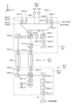
- FIG. 2 is a block diagram showing a system configuration of the machining system according to this embodiment.
- FIG. 3 is a cross-sectional view showing the configuration of the machining head in this embodiment.
- FIG. 4 is a cross-sectional view showing the configuration of the machining head in this embodiment.
- FIG. 5 is a cross-sectional view showing a processing head to which a measuring device (particularly, a measuring head) in this embodiment is attached.
- FIG. 6 is a cross-sectional view showing a processing head to which a measuring device (particularly, a measuring head) in this embodiment is attached.
- FIG. 1 is a perspective view showing the appearance of a machining system according to the present embodiment.
- FIG. 2 is a block diagram showing a system configuration of the machining system according to this embodiment.
- FIG. 3 is a cross-sectional view showing the configuration of the machining head in this embodiment.
- FIG. 4
- FIG. 7 is a cross-sectional view showing an optical system that irradiates a measurement object with measurement light and receives return light from the measurement object.
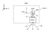
- FIG. 8 is a cross-sectional view showing the structure of an optical system provided in the measurement head in this embodiment.
- FIG. 9 is a cross-sectional view showing a reference member and a measuring head that measures the reference member.
- FIG. 10A is a top view showing a plurality of reference members
- FIG. 10B is a side view showing a plurality of reference members.
- Each of FIGS. 11A to 11E is a side view showing a measurement head that irradiates a reference member with measurement light.
- FIG. 11A to 11E is a side view showing a measurement head that irradiates a reference member with measurement light.
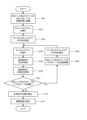
- FIG. 12 is a flowchart showing the flow of a movement error calculation operation for calculating a movement error occurring in the translational movement of at least one of the processing head and the stage.
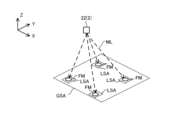
- FIG. 13 shows a schematic diagram of a measurement head that performs a global scan.
- FIG. 14 shows a schematic diagram of a measurement head that performs a local scan.
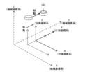
- FIG. 15 shows the measurement coordinate system.
- FIG. 16 shows the measurement coordinate system that moves within the machine coordinate system as the stage moves.
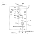
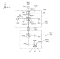
- FIG. 17 shows three measurement points and four reference members.
- FIG. 18 shows the positions of the measurement points in the measurement coordinate system.
- FIG. 19 shows the positions of the measurement points in the machine coordinate system.
- FIG. 20 shows the movement error in the machine coordinate system.
- FIG. 13 shows a schematic diagram of a measurement head that performs a global scan.
- FIG. 14 shows a schematic diagram of a measurement head that performs a local scan.
- FIG. 15 shows the measurement coordinate system.
- FIG. 16 shows the measurement coordinate
- FIG. 21 is a flowchart showing the flow of a movement error calculation operation for calculating a movement error occurring in the rotational movement of at least one of the processing head and the stage.
- FIG. 22 shows the positional relationship between the measurement head and the reference member.
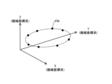
- FIG. 23 shows the position of the reference member in the machine coordinate system.
- FIG. 24 shows the movement error in the machine coordinate system.
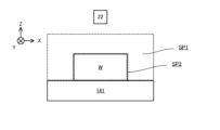
- FIG. 25 is a cross-sectional view showing the positional relationship between the stage, the workpiece, and the measurement head.
- FIG. 26 is a cross-sectional view showing the positional relationship between the stage, the workpiece, and the measurement head.
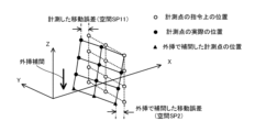
- FIG. 27 shows the movement error calculated by interpolation.
- FIG. 28 is a cross-sectional view showing the positional relationship between the stage, the workpiece, and the measurement head.
- FIG. 29 shows the movement error calculated by interpolation.
- FIG. 30 is a cross-sectional view showing the positional relationship between the stage, the workpiece, and the measuring head.
- FIG. 31 shows how the positions of measurement points in multiple spaces are combined.
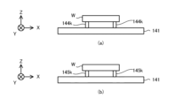
- FIG. 32(a) shows the measurement head in a first situation where no workpiece is placed on the stage
- FIG. 32(b) shows the measurement head in a second situation where a workpiece is placed on the stage.
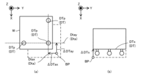
- 33(a) and 33(b) are a top view and a side view, respectively, showing the datum and the reference member of the workpiece.
- 34(a) and 34(b) are a side view and a top view, respectively, showing the datum and the reference member of the workpiece.
- FIG. 35(a) and 35(b) shows a datum point of a workpiece.
- FIG. 36(a) and 36(b) shows a datum point of a workpiece.
- FIG. 37 shows datum points on a workpiece.
- FIG. 38 is a schematic diagram showing the configuration of a processing system in the fourth modified example.
- FIG. 39 is a cross-sectional view showing an example of a measuring head included in a processing system in the fourth modified example.
- 40(a) and 40(b) are cross-sectional views showing an example of a measuring head provided in a processing system in the fourth modified example.
- FIG. 41 is a cross-sectional view showing the positional relationship between the measurement head and the reference member.
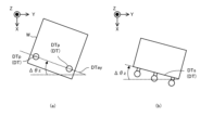
- FIG. 42(a) and 42(b) are cross-sectional views showing a rotationally moving stage and a measurement head that tracks a reference member disposed on the rotationally moving stage.
- FIG. 43 is a graph showing the distance between the measurement head and the reference member calculated from the return light of the reference member while the stage is rotating, in correspondence with the movement trajectory of the reference member.
- FIG. 44 is a cross-sectional view showing a first specific example of a measurement head in the seventh modified example.
- FIG. 45(a) and FIG. 45(b) is a cross-sectional view showing a second specific example of the measurement head in the seventh modified example.
- FIG. 46(b) is a cross-sectional view showing a third specific example of a measurement head in the seventh modified example.
- FIG. 47 is a cross-sectional view showing a fourth specific example of the measurement head in the seventh modified example.
- FIG. 48 is a cross-sectional view showing a fifth specific example of the measurement head in the seventh modified example.
- FIG. 49 is a cross-sectional view showing a sixth specific example of the measurement head in the seventh modified example.
- FIG. 50 shows the pivot point located away from the axis of rotation of the main shaft.
- Figures 51(a) to 51(c) is a cross-sectional view showing how the attitude of the spindle changes when the pivot point is located on the rotation axis of the spindle.
- FIG. 53 is a cross-sectional view showing the configuration of a measurement device according to a ninth modified example.
- FIG. 54 is a cross-sectional view showing the configuration of a first specific example of a measuring device in the ninth modified example.
- FIG. 55 is a sectional view showing the configuration of a second specific example of the measuring device in the ninth modified example.
- FIG. 56 is a cross-sectional view showing the configuration of a third specific example of the measuring device in the ninth modified example.
- FIG. 57 is a cross-sectional view showing a measurement head which repeats a unit measurement operation of irradiating a reference member with measurement light and receiving return light from the reference member.
- FIG. 58 is a cross-sectional view showing a measurement head which repeats a unit measurement operation of irradiating a reference member with measurement light and receiving return light from the reference member.
- FIG. 59 is a block diagram showing a system configuration of a processing system in the eleventh modified example.
- FIG. 60 is a cross-sectional view showing a thermally expanding workpiece.
- Each of Figures 61(a) to 61(d) is a cross-sectional view showing an example of a temperature sensor.
- FIG. 62(a) and 62(b) is a cross-sectional view showing a workpiece placed on a stage via a support member.
- FIG. 63 is a cross-sectional view showing the positional relationship between the reference member FM and each of the measuring head and processing head.
- FIG. 64 is a cross-sectional view showing the positional relationship between the reference member FM and each of the measuring head and processing head.
- FIG. 65 is a block diagram showing a system configuration of a processing system in the twelfth modified example.
- FIG. 66 is a block diagram showing a system configuration of a machining system in the thirteenth modified example.
- FIG. 67 is a block diagram showing a system configuration of a processing system in the fourteenth modified example.
- the machine coordinate system which is an XYZ orthogonal coordinate system defined by the mutually orthogonal X-axis, Y-axis, and Z-axis.
- the X-axis and Y-axis directions of the machine coordinate system are horizontal directions (i.e., specific directions within a horizontal plane), and the Z-axis direction of the machine coordinate system is vertical (i.e., a direction perpendicular to the horizontal plane, essentially an up-down direction).
- the directions of rotation around the X-axis, Y-axis, and Z-axis may be referred to as the ⁇ X direction, ⁇ Y direction, and ⁇ Z direction, respectively.
- the X-axis, Y-axis, and Z-axis refer to the X-axis in the machine coordinate system, the Y-axis in the machine coordinate system, and the Z-axis in the machine coordinate system, respectively.
- FIG. 1 is a perspective view showing the appearance of the machining system SYS (particularly, machine tool 1) in this embodiment.
- Figure 2 is a block diagram showing an example of the system configuration of the machining system SYS in this embodiment.
- the machining system SYS includes a machine tool 1 and a measurement system 2.
- the measurement system 2 is omitted from Figure 1.
- Figure 1 may be considered to mainly show the external appearance of the machine tool 1.
- an apparatus including at least a portion of the measurement system 2 and the machine tool 1 may be referred to as a machine tool.
- at least a portion of the measurement system 2 may be included in the machine tool 1.
- Machine tool 1 is a machining device capable of machining a workpiece W.
- machine tool 1 is equipped with a machining head 11, a head drive system 12, a head position measuring device 13, a stage device 14, a tool exchange device 15, and a machining control device 16.
- the machining head 11 is a processing device for processing the workpiece W.
- the machining head 11 includes a spindle 111 and a head housing 112.
- the machining head 11 will be described below with reference to Figs. 3 and 4 in addition to Figs. 1 and 2.
- Figs. 3 and 4 are cross-sectional views showing the configuration of the machining head 11.
- the machining head 11 may be simply called a head or a spindle head.
- Fig. 1 shows a vertical machine tool as an example, the machine tool 1 is not limited to a vertical machine tool.
- the machine tool 1 may be any well-known machine tool.
- the machine tool 1 may be a horizontal machine tool or a combined machine tool.
- the main shaft 111 is a member that can rotate around the rotation axis RX.
- the main shaft 111 may be, for example, a member that extends along the rotation axis RX (i.e., a member having a longitudinal shape).
- the rotation axis RX of the main shaft 111 is parallel to the Z axis.
- the main shaft 111 may also rotate around a rotation axis RX that intersects the Z axis (for example, a rotation axis RX that is perpendicular to the Z axis or inclined with respect to the Z axis).
- the main shaft 111 may also be referred to as a spindle.
- a tool 113 (i.e., a machining tool) for machining the workpiece W can be attached to the spindle 111.
- the spindle 111 has an attachment portion 1111 for attaching the tool 113.
- the tool 113 is attached to the spindle 111 via the attachment portion 1111.
- the tool 113 attached to the attachment portion 1111 can be removed from the attachment portion 1111. In other words, the tool 113 is attached removably to the spindle 111.
- the state in which "the first object is attached to the second object” may include at least one of the following: “the first object is directly attached to the second object (i.e., the first object is attached to the second object so that the first object and the second object are in contact)” and “the first object is indirectly attached to the second object (i.e., the first object is attached to the second object without the first object and the second object being in contact).”
- the state in which "the first object is indirectly attached to the second object” may also include the state in which "the first object is attached to the second object via a third object that is different from the first and second objects.”
- the spindle 111 is provided with an attachment portion 1111 having a hole 1112 (e.g., a tapered hole) formed at the tip of the spindle 111 (specifically, the tip on the workpiece W side) into which the tool 113 is fitted (or inserted).
- a hole 1112 e.g., a tapered hole
- the shank 1131 of the tool 113 which has a shape complementary to the hole 1112, is fitted (or inserted) into the hole 1112 of the attachment portion 1111, thereby attaching the tool 113 to the spindle 111.
- the attachment portion 1111 may hold the tool 113 attached to the attachment portion 1111.
- the attachment portion 1111 may have at least one of a mechanical chuck, an electrostatic chuck, a hydraulic chuck, and a vacuum suction chuck to hold the tool 113.
- the spindle 111 rotates with the tool 113 attached to it, the tool 113 also rotates around the rotation axis RX. As a result, the rotating tool 113 comes into contact with the workpiece W, machining the workpiece W. In this way, the machine tool 1 (particularly the machining head 11) can machine the workpiece W using the spindle 111 and the tool 113.
- the head housing 112 is a housing that houses the spindle 111.
- the head housing 112 may house the spindle 111 in a housing space formed inside the head housing 112.
- the spindle 111 housed in the head housing 112 may be supported by the head housing 112 via a bearing member (e.g., a bearing) not shown.
- the head drive system 12 moves the processing head 11.
- the head drive system 12 may be referred to as a drive device.
- the head drive system 12 may move the processing head 11, for example, along at least one of the X-axis, Y-axis, and Z-axis. That is, the head drive system 12 may move the processing head 11, for example, along at least one of the translation axes along the X-axis, the Y-axis, and the Z-axis.
- the movement along at least one of the translation axes along the X-axis, the Y-axis, and the Z-axis may be referred to as translation movement.
- the translation axes along the X-axis, the Y-axis, and the Z-axis are referred to as the translation axis (X), the translation axis (Y), and the translation axis (Z), respectively. Additionally, in the following description, unless otherwise specified, the translation axis may mean at least one of the translation axis (X), the translation axis (Y), and the translation axis (Z).
- the head drive system 12 may move the machining head 11 along at least one of the ⁇ X direction, the ⁇ Y direction, and the ⁇ Z direction, in addition to or instead of at least one of the translational axes along the X axis, the Y axis, and the Z axis.
- the head drive system 12 may rotate the machining head 11 around at least one of the rotational axes along the X axis, the Y axis, and the Z axis.
- rotational movement along at least one of the ⁇ X direction (direction around the rotational axis along the X axis), the ⁇ Y direction (direction around the rotational axis along the Y axis), and the ⁇ Z direction (direction around the rotational axis along the Z axis) may be referred to as rotational movement.
- the rotational axis around the X axis, the rotational axis around the Y axis, and the rotational axis around the Z axis are referred to as the rotational axis (X), the rotational axis (Y), and the rotational axis (Z), respectively.
- the rotation axis may mean at least one of the rotation axis (X), the rotation axis (Y), and the rotation axis (Z).
- the operation of moving the processing head 11 in the rotation direction around the rotation axis may be considered to be equivalent to the operation of changing the attitude of the processing head 11.
- the head drive system 12 moves the processing head 11 along each of the translation axis (X) and the translation axis (Z).
- the head drive system 12 may include, for example, a column 121, which is a wall-like member extending upward along the Z axis from a bed 140, which is the base of the stage device 14 described later, an X guide member 122 attached (or formed) to the column 121 and extending along the X axis, an X block member 123 attached to the X guide member 122 and movable along the X guide member 122, a servo motor 124 that generates a driving force for moving the X block member 123, a Z guide member 125 attached (or formed) to the X block member 123 and extending along the Z axis, a Z block member (not shown in FIG.
- the processing head 11 (particularly the head housing 112) may be attached to the Z block member.
- the machining head 11 moves along the translation axis (X) in accordance with the movement of the X-block member 123, and moves along the translation axis (Z) in accordance with the movement of the Z-block member.
- the relative positional relationship between the machining head 11 and the stage 141 changes.
- the relative positional relationship between the machining position where the machining head 11 performs machining and the workpiece W changes.
- the machining position moves with respect to the workpiece W.
- the machine tool 1 may machine the workpiece W while moving the machining head 11.
- the machine tool 1 may machine the desired position of the workpiece W while setting the machining position at the desired position of the workpiece W by moving the machining head 11.
- the machine tool 1 may machine the workpiece W without moving the machining head 11.
- the head position measuring device 13 is capable of measuring the position of the processing head 11.
- An example of the head position measuring device 13 is an encoder.
- the stage device 14 includes a bed 140, a stage 141, and a stage drive system 142.
- the stage 141 and the stage drive system 142 are supported by the bed 140.
- the workpiece W is placed on the stage 141.
- the stage 141 may be referred to as a placement device.
- the stage 141 is capable of supporting the workpiece W placed on the stage 141.
- the stage 141 may be capable of holding the workpiece W placed on the stage 141.
- the stage 141 may be equipped with at least one of a mechanical chuck, an electrostatic chuck, a vacuum chuck, and the like, in order to hold the workpiece W.
- the stage 141 is positioned in a position that allows it to face the machining head 11 (particularly, the spindle 111). In the example shown in FIG. 1, the stage 141 is positioned below the machining head 11 (particularly, the spindle 111). However, the stage 141 may be positioned in a position other than the position below the machining head 11 (particularly, the spindle 111).
- the stage drive system 142 moves the stage 141.
- the stage drive system 142 may also be referred to as a drive device.
- the stage drive system 142 may move the stage 141, for example, along at least one of the X-axis, the Y-axis, and the Z-axis. In other words, the stage drive system 142 may move the stage 141, for example, along at least one of the translational axis (X), the translational axis (Y), and the translational axis (Z).
- the stage drive system 142 may, for example, move the stage 141 along at least one of the ⁇ X direction, the ⁇ Y direction, and the ⁇ Z direction in addition to or instead of at least one of the translational axis (X), the translational axis (Y), and the translational axis (Z).
- the stage drive system 142 may rotate the stage 141 around at least one of the rotational axes (X), the rotational axis (Y), and the rotational axis (Z) in addition to or instead of moving the stage 141 along at least one of the translational axes (X), the translational axis (Y), and the translational axis (Z).
- the operation of moving the stage 141 along the rotational direction around at least one of the rotational axes (X), the rotational axis (Y), and the rotational axis (Z) may be considered equivalent to an operation of changing the attitude of the stage 141.
- the stage drive system 142 moves the stage 141 along the translation axis (Y) and rotates the stage 141 around each of the rotation axis (X) and the rotation axis (Z).
- the stage drive system 142 may include, for example, a Y guide member 1421 attached (or formed) to the bed 140 and extending along the Y axis, a trunnion (Y block member) 1422 attached to the Y guide member 1421 and movable along the Y guide member 1421, a servo motor 1423 that generates a driving force for moving the trunnion 1422, a cradle 1424 attached to the trunnion 1422 and rotatable around the rotation axis (X) relative to the trunnion 1422, and a servo motor (not shown) that generates a driving force for rotating the cradle 1424.
- the stage 141 may be attached to the cradle 1424 so that it can rotate around the rotation axis (Z) relative to the cradle 1424 using the driving force generated by the servo motor (not shown).
- the stage 141 moves along the translation axis (Y) in accordance with the movement of the trunnion 1422, rotates around the rotation axis (X) in accordance with the rotation of the cradle 1424, and rotates around the rotation axis (Z).
- the rotation axis (X) may be referred to as the A-axis.
- the rotation axis (Z) may be referred to as the C-axis.
- the relative positional relationship between the machining head 11 and the stage 141 changes.
- the relative positional relationship between the machining position where the machining head 11 performs machining and the workpiece W changes.
- the machining position moves with respect to the workpiece W.
- the machine tool 1 may machine the workpiece W while moving the stage 141.
- the machine tool 1 may machine the desired position of the workpiece W while setting the machining position at the desired position of the workpiece W by moving the stage 141.
- the machine tool 1 may machine the workpiece W without moving the stage 141.
- the position measurement device 143 is capable of measuring the position of the stage 141.
- An example of the position measurement device 143 is an encoder.
- the tool changer 15 is a device capable of changing the tool 113 attached to the spindle 111.
- the tool changer 15 may take out one tool 113 to be attached to the spindle 111 from a tool magazine (not shown) in which a plurality of tools 113 are stored, and attach the taken out tool 113 to the spindle 111.
- the tool changer 15 may function as an attachment device capable of attaching the tool 113 to the spindle 111.
- the tool changer 15 may remove the tool 113 attached to the spindle 111 from the spindle 111, and store the removed tool 113 in a tool magazine (not shown).
- the tool changer 15 may function as a removal device capable of removing the tool 113 from the spindle 111.
- An automatic tool changer (ATC) used in a machining center or the like may be used as the tool changer 15.
- ATC automatic tool changer
- the machining control device 16 controls the operation of the machine tool 1.
- the machining control device 16 may control the operation of the machining head 11 provided in the machine tool 1 (e.g., the rotation of the spindle 111).
- the machining control device 16 may control the operation of the head drive system 12 provided in the machine tool 1 (e.g., the movement of the machining head 11).
- the machining control device 16 may control the operation of the stage drive system 142 provided in the machine tool 1 (e.g., the movement of the stage 141).
- the machining control device 16 may control the operation of the tool changer 15 provided in the machine tool 1 (i.e., the change of the tool 113 attached to the spindle 111 and the measurement head 22).
- the machining control device 16 may include, for example, an arithmetic device and a storage device.
- the machining control device 16 thus including the arithmetic device may be referred to as an arithmetic unit.
- the arithmetic device may include, for example, at least one of a CPU (Central Processing Unit) and a GPU (Graphics Processing Unit).
- the storage device may include, for example, a memory.
- the machining control device 16 functions as a device that controls the operation of the machine tool 1 by the arithmetic device executing a computer program.
- This computer program is a computer program for causing the arithmetic device to perform (i.e., execute) the operation to be performed by the machining control device 16, which will be described later.
- this computer program is a computer program for causing the machining control device 16 to function so as to cause the machine tool 1 to perform the operation to be described later.
- the computer program executed by the arithmetic device may be recorded in a storage device (i.e., a recording medium) included in the machining control device 16, or may be recorded in any storage medium (e.g., a hard disk or a semiconductor memory) that is built into the machining control device 16 or that can be externally attached to the machining control device 16.
- the arithmetic device may download the computer program to be executed from a device external to the processing control device 16 via a network interface. Note that the processing control device 16 does not need to be equipped with a storage device.
- the machining control device 16 does not have to be provided inside the machine tool 1.
- the machining control device 16 may be provided outside the machine tool 1 as a server or the like.
- the machining control device 16 and the machine tool 1 may be connected by a wired and/or wireless network (or a data bus and/or a communication line).
- a wired network a network using a serial bus type interface, such as at least one of IEEE1394, RS-232x, RS-422, RS-423, RS-485, and USB, may be used.
- a network using a parallel bus type interface may be used as the wired network.
- a network using an interface compliant with Ethernet such as at least one of 10BASE-T, 100BASE-TX, and 1000BASE-T
- a network using radio waves may be used.
- An example of a network using radio waves is a network conforming to IEEE802.1x (for example, at least one of a wireless LAN and Bluetooth (registered trademark)).
- a network using infrared rays may be used as a wireless network.
- a network using optical communication may be used as a wireless network.
- the machining control device 16 and the machine tool 1 may be configured to be able to transmit and receive various information via the network.
- the machining control device 16 may be capable of transmitting information such as commands and control parameters to the machine tool 1 via the network.
- the machine tool 1 may be equipped with a receiving device that receives information such as commands and control parameters from the machining control device 16 via the network.
- the machine tool 1 may be equipped with a transmitting device (i.e., an output device that outputs information to the machining control device 16) that transmits information such as commands and control parameters to the machining control device 16 via the network.
- a first control device that performs a part of the processing performed by the machining control device 16 may be provided inside the machine tool 1, while a second control device that performs another part of the processing performed by the machining control device 16 may be provided outside the machine tool 1.
- a computational model that can be constructed by machine learning may be implemented in the processing control device 16 by the computation device executing a computer program.
- An example of a computational model that can be constructed by machine learning is, for example, a computational model including a neural network (so-called artificial intelligence (AI)).
- learning of the computational model may include learning of parameters of the neural network (for example, at least one of weights and biases).
- the processing control device 16 may use the computational model to control the operation of the machine tool 1.
- the operation of controlling the operation of the machine tool 1 may include the operation of controlling the operation of the machine tool 1 using the computational model.
- a computational model that has been constructed by offline machine learning using teacher data may be implemented in the processing control device 16.
- the computational model implemented in the processing control device 16 may be updated on the processing control device 16 by online machine learning.
- the machining control device 16 may control the operation of the machine tool 1 using a computational model implemented in a device external to the machining control device 16 (particularly, a device provided outside the machine tool 1) in addition to or instead of the computational model implemented in the machining control device 16.
- the recording medium for recording the computer program executed by the processing control device 16 may be at least one of the following: CD-ROM, CD-R, CD-RW, flexible disk, MO, DVD-ROM, DVD-RAM, DVD-R, DVD+R, DVD-RW, DVD+RW, optical disks such as Blu-ray (registered trademark), magnetic media such as magnetic tape, magneto-optical disk, semiconductor memory such as USB memory, and any other medium capable of storing a program.
- the recording medium may include a device capable of recording a computer program (for example, a general-purpose device or a dedicated device in which a computer program is implemented in a state in which it can be executed in at least one of the forms of software and firmware, etc.).
- each process or function included in the computer program may be realized by a logical processing block realized in the processing control device 16 by the processing control device 16 (i.e., a computer) executing the computer program, or may be realized by hardware such as a predetermined gate array (FPGA (Field Programmable Gate Array), ASIC (Application Specific Integrated Circuit)) provided in the processing control device 16, or may be realized in a form that combines logical processing blocks and partial hardware modules that realize some elements of the hardware.
- FPGA Field Programmable Gate Array
- ASIC Application Specific Integrated Circuit
- the measurement system 2 is capable of measuring a measurement object.
- the measurement system 2 includes a measurement device 20 and a measurement control device 24.
- the measuring device 20 is capable of measuring the object to be measured.
- the measuring device 20 may be capable of measuring the characteristics of the object to be measured.
- the characteristics of the object to be measured may include, for example, at least one of the position of the object to be measured, the shape of the object to be measured, the distance between the measuring device 20 and the object to be measured, the direction of the object to be measured as seen from the measuring device 20, the reflectance of the object to be measured, the transmittance of the object to be measured, the temperature of the object to be measured, the internal structure of the object to be measured, and the surface roughness of the object to be measured.
- the position of the measurement object may include the position of the surface of the measurement object.
- the position of the surface of the measurement object may include the position of at least a part of the surface of the measurement object.
- the position of the measurement object may mean the position of the measurement object in a machine coordinate system used as a reference in the machining system SYS (i.e., absolute position).
- the position of the measurement object may mean the position of the measurement object relative to the measuring device 20 (i.e., relative position).
- the position of the measurement object may mean the position of the measurement object in a measurement coordinate system (described later) that is used by the measuring device 20 as a coordinate system different from the machine coordinate system.
- the measurement device 20 measures the distance between the measurement device 20 and the measurement object (specifically, the distance between the measurement head 22 described later and the measurement object), and the measurement control device 24 calculates the position of the measurement object based on that distance. Therefore, the operation of at least measuring the position of the measurement object may be considered to essentially mean the operation of measuring the distance from the measurement head 22 to the measurement object, which is necessary to calculate the position of the measurement object.
- the position of the surface of the measurement object changes depending on the shape of the surface of the measurement object.
- the operation of measuring the position of the measurement object may be considered equivalent to the operation of measuring the shape of the measurement object.
- the shape of the measurement object may include at least one of the one-dimensional shape, two-dimensional shape, and three-dimensional shape of the measurement object.
- the measurement object may include, for example, the workpiece W that is processed by the processing head 11.
- the measurement object may include, for example, any object that is placed on the stage 141. Any object that is placed on the stage 141 may include, for example, the workpiece W.
- the measurement object may include a reference member FM that is used in the movement error calculation operation described below.
- the measurement object may include, for example, the stage 141.
- the measuring device 20 may be capable of measuring the object of measurement without contact.
- the measuring device 20 may be capable of measuring the object of measurement optically.
- the measuring device 20 may be capable of measuring the object of measurement electrically.
- the measuring device 20 may be capable of measuring the object of measurement magnetically.
- the measuring device 20 may be capable of measuring the object of measurement thermally.
- the measuring device 20 may be capable of measuring the object of measurement acoustically.
- the measuring device 20 may be capable of measuring the object of measurement using a probe that physically contacts the object of measurement.
- the measurement device 20 is capable of optically measuring the measurement object.
- the measurement device 20 may be referred to as an optical measurement device.
- the measurement device 20 measures the measurement object by irradiating the measurement object with measurement light ML and receiving at least a portion of the light from the measurement object irradiated with the measurement light ML.
- the light from the measurement object irradiated with the measurement light ML is light from the measurement object that is generated by irradiation with the measurement light ML.
- the light from the measurement object irradiated with the measurement light ML that enters the measurement device 20 i.e., is received by the measurement device 20
- return light RL the light from the measurement object irradiated with the measurement light ML that enters the measurement device 20
- the light from the measurement object generated by irradiation with the measurement light ML may include specular reflected light generated by the measurement object when irradiated with the measurement light ML.
- the light from the measurement object generated by irradiation with the measurement light ML may include, in addition to or instead of specular reflected light, diffuse reflected light generated by the measurement object when irradiated with the measurement light ML.
- the light from the measurement object generated by irradiation with the measurement light ML may include diffracted light generated by the measurement object when irradiated with the measurement light ML in addition to or instead of at least one of specular reflected light and diffuse reflected light.
- the measurement device 20 may include, for example, a measurement light source 21, a measurement head 22, and an output interface 23.
- the configuration and operation of the measurement device 20 will be described in detail later, but an overview of the measurement device 20 will be briefly described here.
- the measurement light source 21 can generate measurement light ML.
- the measurement head 22 is attached to the processing head 11. That is, the measurement head 22 is arranged on the processing head 11.
- the measurement head 22 attached to the processing head 11 may be fixed to the processing head 11.
- the measurement head 22 attached to the processing head 11 may be removable from the processing head 11.
- FIG. 1 the measurement head 22 attached to the processing head 11 is not shown in order to simplify the drawing, but the measurement head 22 attached to the processing head 11 is shown in FIG. 5 to FIG.
- the measurement head 22 irradiates the measurement light ML to the measurement object. Furthermore, the measurement head 22 receives return light RL from the measurement object irradiated with the measurement light ML.
- the measurement head 22 may also be referred to as an optical device.
- the output interface 23 can output the measurement results of the measurement object by the measurement head 22 (i.e., the reception results of the return light RL from the measurement object) to the measurement control device 24.
- the measurement device 20 does not have to include the measurement light source 21.
- the measurement light source 21 may be a light source arranged outside the measurement device 20.
- the measurement light source 21 may be arranged outside the machine tool 1.
- the measurement light source 21 may be arranged outside the measurement system 2.
- the measurement light source 21 may be arranged outside the measurement device 20 (typically outside the measurement system 1) and at a predetermined position inside the machine tool 1.
- An example of a predetermined position outside the measurement device 20 (typically outside the measurement system 1) and inside the machine tool 1 is, for example, a predetermined position outside or inside a housing that houses at least one of the machining head 11, head drive system 12, stage device 14, and machining control device 16 of the machine tool 1.
- the measurement light source 21 may be arranged outside the measurement device 20 and at a predetermined position inside the measurement system 2.
- a predetermined position outside the measurement device 20 and inside the measurement system 2 is, for example, a predetermined position outside or inside a housing that houses the measurement control device 24 of the measurement system 2.
- the measurement head 22 of the measurement device 20 may irradiate the measurement object with measurement light ML generated by a measurement light source 21 disposed outside the measurement device 20.
- the measurement head 22 may be attachable to the spindle 111 of the machine tool 1. That is, the measurement head 22 provided by the measuring device 20 may be attached to the spindle 111 in addition to the tool 113.
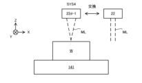
- the tool exchange device 15 may function as an attachment device capable of attaching the measurement head 22 to the spindle 111. That is, the tool exchange device 15 may remove the measurement head 22 from a tool magazine (not shown) in which the measurement head 22 is stored in addition to the tool 113 (or a head magazine (not shown) in which the measurement head 22 is stored, which is different from the tool magazine in which the tool 113 is stored) and attach the removed measurement head 22 to the spindle 111.
- the tool exchange device 15 may also function as a removal device capable of removing the measurement head 22 from the spindle 111. That is, the tool exchange device 15 may remove the measurement head 22 attached to the spindle 111 from the spindle 111 and store the removed measurement head 22 in a tool magazine (not shown) or a head magazine (not shown).
- the measurement head 22 does not have to be attached to the spindle 111.
- the measurement head 22 may be attached to the head housing 112.
- the measurement control device 24 controls the operation of the measurement system 2.
- the measurement control device 24 may control the measurement device 20 to measure the measurement object.
- the measurement control device 24 since the measurement head 22 is attached to the machine tool 1 (particularly, the spindle 111) as described above, the head drive system 12 of the machine tool 1 moves the measurement head 22. Therefore, the measurement control device 24 may control the machine tool 1 (particularly, the head drive system 12) together with the processing control device 16 so that the measurement device 20 moves to a desired position. In other words, the measurement control device 24 may control the movement of the processing head 11 together with the processing control device 16.
- the measurement control device 24 may control the machine tool 1 (particularly, the stage drive system 142) together with the processing control device 16 so that the measurement object moves to a desired position.
- the measurement control device 24 may control the movement of the stage 141 together with the processing control device 16.
- the measurement control device 24 since the measurement head 22 is attached to the machine tool 1 (spindle 111), the measurement control device 24 does not have to control the head drive system 12. In this case, the processing control device 16 may control the head drive system 12. In addition, since the measurement head 22 is attached to the machine tool 1 (spindle 111), the processing control device 16 does not have to control the head drive system 12. In this case, the measurement control device 24 may control the head drive system 12. In addition, the measurement control device 24 does not have to control the stage drive system 142. In this case, the processing control device 16 may control the stage drive system 142. In addition, the processing control device 16 does not have to control the stage drive system 142. In this case, the measurement control device 24 may control the stage drive system 142.
- the measurement control device 24 performs a movement error calculation operation.
- the movement error calculation operation may include an operation of calculating a movement error (in other words, a motion error) occurring in the movement of at least one of the machining head 11 and the stage 141 based on the measurement result of the measurement object by the measurement head 22.
- the movement error calculation operation may include an operation of generating information on the movement error occurring in the movement of at least one of the machining head 11 and the stage 141 as information for controlling the machine tool 1 based on the measurement result of the measurement object by the measurement head 22.
- the movement error calculation operation may include an operation of generating information for controlling the machine tool 1 (particularly, information different from the information on the movement error) based on the calculated movement error (information on the generated movement error).
- the measurement control device 24 may output the generated information to the processing control device 16.
- the processing control device 16 may control the machine tool 1 based on the information.
- the movement error calculation operation will be described in detail later with reference to FIG. 9 and the like, so a description thereof will be omitted here.
- the movement error may be referred to as a spatial precision error.
- the measurement control device 24 that performs the movement error calculation operation may be referred to as a movement error calculation device, a calculation device, or a calculation device.
- the measurement system 2 including the measurement device 20 and the measurement control device 24 may be referred to as a movement error calculation system, a calculation system, or a calculation system.
- a system including the measurement control device 24 and a reference member FM described below that is used to perform the movement error calculation operation may be referred to as a movement error calculation system, a calculation system, or a calculation system.
- a system including the measurement control device 24 and the reference member FM may be referred to as the measurement system 2.
- a system including the reference member FM, the measurement device 20, and the measurement control device 24 may be referred to as a movement error calculation system, a calculation system, or a calculation system.
- a system including the reference member FM, the measurement device 20, and the measurement control device 24 may be referred to as the measurement system 2.
- a system including the measurement head 22 and the measurement control device 24 may be referred to as the measurement system 2.
- the measurement control device 24 may include, for example, an arithmetic device and a storage device.
- the measurement control device 24 thus including the arithmetic device may be referred to as an arithmetic unit.
- the arithmetic device may include, for example, at least one of a CPU (Central Processing Unit) and a GPU (Graphics Processing Unit).
- the storage device may include, for example, a memory.
- the measurement control device 24 functions as a device that controls the operation of the measurement device 20 by the arithmetic device executing a computer program.
- the measurement control device 24 controls at least a part of the operation of the machine tool 1 (for example, at least one of the head drive system 12 and the stage drive system 142), the measurement control device 24 functions as a device that controls the operation of the machine tool 1 by the arithmetic device executing a computer program.
- the measurement control device 24 does not need to control at least a part of the operation of the machine tool 1, the measurement control device 24 does not need to function as a device that controls the operation of the machine tool 1.
- This computer program is a computer program for making the arithmetic device perform (i.e., execute) the operation to be performed by the measurement control device 24, which will be described later.
- this computer program is a computer program for making the measurement control device 24 function so as to make the measurement device 20 (and further the machine tool 1) perform the operation to be described later.
- the computer program executed by the arithmetic device may be recorded in a storage device (i.e., a recording medium) included in the measurement control device 24, or may be recorded in any storage medium (e.g., a hard disk or semiconductor memory) that is built into the measurement control device 24 or that can be externally attached to the measurement control device 24.
- the arithmetic device may download the computer program to be executed from a device external to the measurement control device 24 via a network interface. Note that the measurement control device 24 does not need to have a storage device.
- the measurement control device 24 does not have to be provided inside the measurement system 2.
- the measurement control device 24 may be provided outside the measurement system 2 as a server or the like.
- the measurement control device 24 and the measurement system 2 may be connected by a wired and/or wireless network (or a data bus and/or a communication line).
- a wired network a network using a serial bus type interface, such as at least one of IEEE1394, RS-232x, RS-422, RS-423, RS-485, and USB, may be used.
- a network using a parallel bus type interface may be used as a wired network.
- a network using an interface compliant with Ethernet such as at least one of 10BASE-T, 100BASE-TX, and 1000BASE-T
- a network using radio waves may be used.
- An example of a network using radio waves is a network conforming to IEEE802.1x (for example, at least one of a wireless LAN and Bluetooth (registered trademark)).
- a network using infrared rays may be used as a wireless network.
- a network using optical communication may be used as a wireless network.
- the measurement control device 24 and the measurement system 2 may be configured to be able to transmit and receive various information via the network.
- the measurement control device 24 may be able to transmit information such as commands and control parameters to the measurement system 2 via the network.
- the measurement system 2 may include a receiving device that receives information such as commands and control parameters from the measurement control device 24 via the network.
- the measurement system 2 may include a transmitting device (i.e., an output device that outputs information to the measurement control device 24) that transmits information such as commands and control parameters to the measurement control device 24 via the network.
- a first control device that performs a part of the processing performed by the measurement control device 24 may be provided inside the measurement system 2
- a second control device that performs another part of the processing performed by the measurement control device 24 may be provided outside the measurement system 2.
- At least a portion of the processing performed by the measurement control device 24 may be performed by the processing control device 16.
- the processing control device 16 may perform at least a portion of the movement error calculation operation performed by the measurement control device 24. Conversely, at least a portion of the processing performed by the processing control device 16 may be performed by the measurement control device 24.
- the machining system SYS may be provided with a control device capable of functioning as the measurement control device 24 and the machining control device 16, instead of the measurement control device 24 and the machining control device 16.
- the machining system SYS may be provided with a control device in which the measurement control device 24 and the machining control device 16 are integrated.
- the machine tool 1 may be provided with a control device capable of functioning as the measurement control device 24 and the machining control device 16, instead of the machining control device 16.
- the measurement system 2 may or may not be provided with the measurement control device 24.
- the measurement system 2 may be provided with a control device capable of functioning as the measurement control device 24 and the machining control device 16, instead of the measurement control device 24.
- the machine tool 1 may or may not be provided with the machining control device 16.
- a computation model that can be constructed by machine learning may be implemented in the measurement control device 24 by the computation device executing a computer program.
- An example of a computation model that can be constructed by machine learning is, for example, a computation model including a neural network (so-called artificial intelligence (AI)).
- learning of the computation model may include learning of parameters of the neural network (for example, at least one of the weight and bias).
- the measurement control device 24 may use the computation model to control the operation of the measurement system 2.
- the operation of controlling the operation of the measurement system 2 may include the operation of controlling the operation of the measurement system 2 using the computation model.
- a computation model that has already been constructed by offline machine learning using teacher data may be implemented in the measurement control device 24.
- the computation model implemented in the measurement control device 24 may be updated by online machine learning on the measurement control device 24.
- the measurement control device 24 may control the operation of the measurement system 2 using a calculation model implemented in a device external to the measurement control device 24 (particularly, a device provided outside the measurement system 2) in addition to or instead of the calculation model implemented in the measurement control device 24.
- the recording medium for recording the computer program executed by the measurement control device 24 may be at least one of the following: CD-ROM, CD-R, CD-RW, flexible disk, MO, DVD-ROM, DVD-RAM, DVD-R, DVD+R, DVD-RW, DVD+RW, optical disks such as Blu-ray (registered trademark), magnetic media such as magnetic tape, magneto-optical disk, semiconductor memory such as USB memory, and any other medium capable of storing a program.
- the recording medium may include a device capable of recording a computer program (for example, a general-purpose device or a dedicated device in which a computer program is implemented in a state in which it can be executed in at least one of the forms of software and firmware, etc.).
- each process or function included in the computer program may be realized by a logical processing block realized in the measurement control device 24 by the measurement control device 24 (i.e., a computer) executing the computer program, or may be realized by hardware such as a predetermined gate array (FPGA (Field Programmable Gate Array), ASIC (Application Specific Integrated Circuit)) provided in the measurement control device 24, or may be realized in a form that combines logical processing blocks and partial hardware modules that realize some elements of the hardware.
- FPGA Field Programmable Gate Array
- ASIC Application Specific Integrated Circuit
- the output device 25 is a device that outputs information to the outside of the measurement system 2.
- the output device 25 may output information as an image. That is, the output device 25 may include a display device (a so-called display) capable of displaying an image.
- the output device 25 may output information as sound. That is, the output device 25 may include an audio output device (a so-called speaker) capable of outputting sound.
- the output device 25 may output information on paper. That is, the output device 25 may include a printing device (a so-called printer) capable of printing desired information on paper.
- the output device 25 may output information as data to a recording medium that can be attached externally to the measurement system 2.
- the output device 25 may output (i.e., transmit) information as data via a communication line. That is, the output device 25 may function as a communication device.
- the measurement system 2 does not have to include the output device 25.
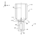
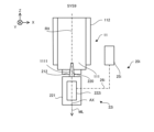
- Fig. 5 is a cross-sectional view showing the machining head 11 to which the measuring device 20 (particularly, the measuring head 22) is attached.
- the measurement head 22 is attached to the machining head 11.
- the measurement head 22 includes a head housing 221, which is attached to the machining head 11.
- the measurement head 22 is attached to the spindle 111 of the machining head 11. That is, the measurement head 22 is attached to the spindle 111 instead of the tool 113.
- the head housing 221 is attached to the attachment portion 1111 of the spindle 111. In the example shown in FIG.
- the spindle 111 includes the attachment portion 1111 in which the hole 1112 is formed, and therefore the shank 220, which corresponds to the protruding portion of the head housing 221 having a shape complementary to the hole 1112, is fitted (or inserted) into the hole 1112 of the attachment portion 1111, thereby attaching the head housing 221 to the spindle 111.
- the attachment portion 1111 may hold the head housing 221.
- the mounting portion 1111 may be equipped with at least one of a mechanical chuck, a hydraulic chuck, an electrostatic chuck, a vacuum chuck, etc. to hold the head housing 221.
- the head housing 221 (i.e., the measurement head 22) attached to the attachment portion 1111 can be removed from the attachment portion 1111. That is, the head housing 221 (i.e., the measurement head 22) is attached to the spindle 111 in a detachable manner. For example, when the measurement head 22 is attached to the spindle 111, the tool 113 is removed from the spindle 111. On the other hand, when the tool 113 is attached to the spindle 111, the measurement head 22 is removed from the spindle 111. As described above, the head housing 221 is attached and detached, and the tool 113 is attached and detached by the tool exchange device 15. However, an operator of the machining system SYS may manually attach and detach the measurement head 22 to the spindle 111, and/or the tool 113 to the spindle 111.
- the measurement head 22 may be attached to a part of the machining head 11 other than the spindle 111.
- the measurement head 22 may be attached to a part of the machining head 11 other than the spindle 111 as long as the measurement head 22 can measure the measurement object.
- FIG. 6 which is a cross-sectional view showing the machining head 11 to which the measurement device 20 (particularly the measurement head 22) is attached
- the measurement head 22 may be attached to the head housing 112 of the machining head 11.
- the head housing 221 may be attached to the head housing 112 of the machining head 11.
- the head housing 221 may be attached to the machining head 11 at a position away from the rotation axis RX of the spindle 111 along the direction intersecting the rotation axis RX.
- the head housing 221 is attached to the side of the head housing 112.
- the measurement head 22 does not have to be detachable from the machining head 11. In other words, the measurement head 22 does not have to be detachably attached to the machining head 11.
- the measurement head 22 may remain attached to the machining head 11 even during the machining period in which the machining head 11 uses the tool 113 to machine the workpiece W.
- the measurement head 22 may remain attached to the machining head 11 at all times. However, even if the measurement head 22 is attached to a part of the machining head 11 other than the spindle 111, the measurement head 22 may be detachably attached to the machining head 11.
- the measuring head 22 may be attached at a fixed position relative to the processing head 11.
- the measuring head 22 may be attached to the processing head 11 so that the positional relationship between the processing head 11 and the measuring head 22 is fixed (i.e., does not change).
- the measuring head 22 may be directly fixed and attached to the processing head 11.
- the measuring head 22 may be indirectly fixed and attached to the processing head 11.
- the measuring head 22 may be fixed to a support member, one side of which is directly fixed to the processing head 11, the other side of which is directly fixed to the processing head 11. Both the state in which the measuring head 22 is directly fixed to the processing head 11 and the state in which the measuring head 22 is directly fixed to the processing head 11 correspond to the state in which the measuring head 22 is attached at a fixed position relative to the processing head 11.
- the positional relationship between the processing head 11 and the measuring head 22 is usually fixed, unless the measuring device 20 is equipped with a drive system for moving the measuring head 22 independently of the processing head 11. Furthermore, when the measurement head 22 is attached to the spindle 111 of the processing head 11, since the spindle 111 can rotate around the rotation axis RX, the rotation of the spindle 111 may be locked using a mechanical fixing mechanism or the like when the measurement head 22 is attached to the spindle 111.
- the measurement head 22 does not have to be attached at a position where the positional relationship with the processing head 11 is fixed.
- the positional relationship between the processing head 11 and the measurement head 22 may be variable.
- the measurement device 20 may be equipped with a drive system for moving the measurement head 22 independently of the processing head 11.
- this drive system may be configured to move the processing head 11 and the measurement head 22 relatively along the rotation axis RX.
- the measurement head 22 may interfere with the processing of the workpiece W during the processing period in which the processing head 11 processes the workpiece W with the tool 113.
- the positional relationship between the machining head 11 and the measurement head 22 during at least a portion of the measurement period during which the measuring device 20 measures the measurement object may be different from the positional relationship between the machining head 11 and the measurement head 22 during at least a portion of the processing period during which the machining head 11 processes the workpiece W.
- the positional relationship between the machining head 11 and the measurement head 22 may be set to a first relationship in which the measurement head 22 does not interfere with the processing of the workpiece W, and during at least a portion of the measurement period, the positional relationship between the machining head 11 and the measurement head 22 may be set to a second relationship different from the first relationship (for example, a second relationship in which the measuring device 20 can measure the measurement object using the measurement head 22).
- the measurement control device 24 may use the head position measurement device 13 to measure the amount of movement along the rotation axis RX of the machining head 11 and the measurement head 22, respectively. Furthermore, the measurement control device 24 may measure the movement error along this movement axis in advance, and reflect this previously measured movement error when calculating the movement error of the machine tool 1 by performing the movement error calculation operation described above.
- the drive system for moving the measurement head 22 is not limited to the rotation axis RX, but may be configured to move the processing head 11 and the measurement head 22 relative to each other along a direction different from the direction along the rotation axis RX.
- the measurement head 22 When the measurement head 22 is attached to the processing head 11, the measurement head 22 also moves with the movement of the processing head 11. In other words, the measurement head 22 moves in the same way as the processing head 11. For this reason, the head drive system 12 that moves the processing head 11 may be considered to function as a head drive system for moving the measurement head 22. In this case, the movement of the measurement head 22 changes the relative positional relationship between the measurement position where the measurement head 22 performs the measurement and the measurement object. In other words, the measurement position moves with respect to the measurement object.
- the machine tool 1 may measure the measurement object while moving the measurement head 22 by moving the processing head 11.
- the processing system SYS may measure the desired position of the measurement object while setting the measurement position at the desired position of the measurement object by moving the measurement head 22.
- the processing system SYS may measure the measurement object without moving the measurement head 22.
- the measurement head 22 may also rotate around the rotation axis RX as the spindle 111 rotates.
- the measurement control device 24 may obtain in advance a movement error associated with the rotational movement of the spindle 111, and may reflect this previously measured movement error when calculating the movement error of the machine tool 1 by performing the movement error calculation operation described above.
- the measurement head 22 further includes an optical system 222.
- the optical system 222 is housed in an internal storage space of the head housing 221. For this reason, the optical system 222 is attached to the machining head 11 via the head housing 221.
- unwanted materials e.g., cutting chips, cutting fluid, etc.
- the measurement head 22 may include a measurement light source 21.
- the measurement light source 21 may be housed in the internal space of the head housing 221. In this case, the measurement light source 21 may be considered to constitute a part of the optical system 222.
- the measurement light source 21 may not be attached to the processing head 11, or may be attached to a part of the processing head 11 other than the spindle 111.
- the measurement device 202 includes multiple measurement light sources 21 (for example, measurement light sources 21#1 and 21#2 described later), at least one of the multiple measurement light sources 21 may not be attached to the processing head 11, or may be attached to a part of the processing head 11 other than the spindle 111.
- the optical system 222 is used to irradiate the measurement light ML from the measurement light source 21 onto the measurement object. Furthermore, the optical system 222 is used to receive the return light RL from the measurement object. Specifically, as shown in FIG. 7, which is a cross-sectional view of the optical system 222 that irradiates the measurement light ML onto the measurement object and receives the return light RL from the measurement object, the measurement light ML generated by the measurement light source 21 enters the optical system 222 from the measurement light source 21 via an optical transmission member (not shown), such as an optical fiber. The optical system 222 emits the measurement light ML that has entered the optical system 222 towards the measurement object. In other words, the optical system 222 irradiates the measurement light ML onto the measurement object.
- the light resulting from the irradiation of the measurement light ML is emitted from the measurement object.
- the light resulting from the irradiation of the measurement light ML may include reflected light of the measurement light ML irradiated onto the measurement object.
- the light generated due to the irradiation of the measurement light ML may include scattered light of the measurement light ML irradiated onto the measurement object.
- the light generated due to the irradiation of the measurement light ML may include transmitted light of the measurement light ML irradiated onto the measurement object.
- the light generated due to the irradiation of the measurement light ML may include diffracted light of the measurement light ML irradiated onto the measurement object.
- At least a portion of the light generated due to the irradiation of the measurement light ML is incident on the optical system 222 as return light RL from the measurement object.
- the light component of the light generated due to the irradiation of the measurement light ML that travels along the optical path of the measurement light ML is incident on the optical system 222 as return light RL.
- the optical path of the measurement light ML emitted from the optical system 222 and incident on the measurement object may be the same as the optical path of the return light RL emitted from the measurement object and incident on the optical system 222.
- the optical path of the measurement light ML between the optical system 222 and the measurement object may be the same as the optical path of the return light RL between the optical system 222 and the measurement object.
- the return light RL may be light that is mainly composed of specularly reflected light of the measurement light ML.
- the return light RL may include light other than the specularly reflected light of the measurement light ML (for example, at least one of the diffusely reflected light, scattered light, transmitted light, and diffracted light of the measurement light ML).
- the return light RL when the measurement light ML is obliquely incident on the measurement object (in other words, non-perpendicularly incident), the return light RL may be light mainly composed of the diffusely reflected light of the measurement light ML.
- the return light RL when the measurement light ML is obliquely incident on the measurement object, the return light RL may include light other than the diffusely reflected light of the measurement light ML (for example, at least one of the specularly reflected light, scattered light, transmitted light, and diffracted light of the measurement light ML).
- FIG. 8 is a cross-sectional view showing the structure of the optical system 222.
- the optical system 222 includes a beam splitter 2221, a beam splitter 2222, a photodetector (measurement unit) 2223, a beam splitter 2224, a mirror 2225, a photodetector (measurement unit) 2226, a mirror 2227, and a galvanometer mirror 2228.
- At least one of the measurement light source 21, the beam splitter 2221, the beam splitter 2222, the photodetector 2223, the beam splitter 2224, the mirror 2225, and the photodetector 2226 does not have to be housed in the head housing 221.
- at least one of the measurement light source 21, the beam splitter 2221, the beam splitter 2222, the photodetector 2223, the beam splitter 2224, the mirror 2225, and the photodetector 2226 does not have to be attached to the machining head 11, or may be attached to a part of the machining head 11 other than the main shaft 111.
- At least one of the measurement light source 21, the beam splitter 2221, the beam splitter 2222, the photodetector 2223, the beam splitter 2224, the mirror 2225, and the photodetector 2226 may be housed in a housing different from the head housing 221 attached to the spindle 111 of the machining head 11.
- the housing different from the head housing 221 may not be attached to the machining head 11, may be attached to a part of the machining head 11 different from the spindle 111, or may be attached outside or inside a housing that houses at least one of the machining head 11, the head drive system 12, the stage device 14, the measurement device 20, the machining control device 16, and the measurement control device 24 of the machine tool 1.
- At least one of the measurement light source 21, the beam splitter 2221, the beam splitter 2222, the photodetector 2223, the beam splitter 2224, the mirror 2225, and the photodetector 2226 may be located outside the machine tool 1, not limited to inside the machine tool 1.
- the measurement light ML from the measurement light source 21 is incident on the beam splitter 2221.
- the two measurement light beams ML generated by the two measurement light sources 21 (specifically, measurement light sources 21#1 and 21#2) are incident on the beam splitter 2221.
- the measurement device 20 is equipped with a measurement light source 21#1 and a measurement light source 21#2.
- the two measurement light sources 21 may each emit two measurement light beams ML that are phase-synchronized with each other and are coherent.
- the measurement device 20 may be equipped with a single measurement light source 21.
- the two measurement light sources 21 have different oscillation frequencies. Therefore, the two measurement light ML emitted by the two measurement light sources 21 are two measurement light ML with different frequencies.
- the measurement light source 21 When the measurement light source 21 generates pulsed light as the measurement light ML, the two measurement light ML emitted by the two measurement light sources 21 are two measurement light ML with different pulse frequencies (e.g., the number of pulsed lights per unit time, which is the reciprocal of the emission period of the pulsed light).
- the measurement light source 21#1 may emit a measurement light ML with a pulse frequency of 25 GHz
- the measurement light source 21#2 may emit a measurement light ML with a pulse frequency of 25 GHz+ ⁇ (e.g., +100 kHz).
- the measurement light ML generated by the measurement light source 21#1 is referred to as “measurement light ML#1”
- the measurement light ML generated by the measurement light source 21#2 is referred to as “measurement light ML#2”.
- the two measurement light sources 21 may have the same oscillation frequency.
- the measurement light source 21 includes an optical comb light source.
- the optical comb light source is a light source capable of generating light including frequency components that are evenly spaced on the frequency axis (hereinafter referred to as an "optical frequency comb") as pulsed light.
- the measurement light source 21 emits pulsed light including frequency components that are evenly spaced on the frequency axis as the measurement light ML.
- the measurement light source 21 may include a light source other than the optical comb light source.
- the two measurement beams ML#1 and ML#2 incident on the beam splitter 2221 are emitted toward the beam splitter 2222.
- the beam splitter 2221 emits the measurement beams ML2#1 and ML#2, which are incident on the beam splitter 2221 from different directions, in the same direction (i.e., the direction in which the beam splitter 2222 is disposed).
- Beam splitter 2222 emits measurement light ML#1-1, which is a part of measurement light ML#1 incident on beam splitter 2222, toward photodetector 2223. Beam splitter 2222 emits measurement light ML#1-2, which is another part of measurement light ML#1 incident on beam splitter 2222, toward beam splitter 2224. Beam splitter 2222 emits measurement light ML#2-1, which is a part of measurement light ML2#2 incident on beam splitter 2222, toward photodetector 2223. Beam splitter 2222 emits measurement light ML#2-2, which is another part of measurement light ML#2 incident on beam splitter 2222, toward beam splitter 2224.
- the measurement light ML#1-1 and ML#2-1 emitted from the beam splitter 2222 are incident on the photodetector 2223.
- the photodetector 2223 receives the measurement light ML#1-1 and the measurement light ML#2-1.
- the photodetector 2223 receives and detects the measurement light ML#1-1 and the measurement light ML#2-1.
- the state in which "an object receives light” may mean the state in which "light is incident on an object”. Therefore, in this embodiment, the state in which "an object receives light” may mean the state in which "an object capable of detecting light receives light” or the state in which "an object not capable of detecting light receives light”.
- the photodetector 2223 receives and detects the interference light generated by the interference between the measurement light ML#1-1 and the measurement light ML#2-1.
- the operation of receiving the interference light generated by the interference between the measurement light ML#1-1 and the measurement light ML#2-1 may be considered equivalent to the operation of receiving the measurement light ML#1-1 and the measurement light ML#2-1.
- the detection result by the photodetector 2223 i.e., the reception result of the interference light
- the measurement light ML#1-2 and ML#2-2 emitted from the beam splitter 2222 enter the beam splitter 2224.
- the beam splitter 2224 emits at least a portion of the measurement light ML#1-2 that entered the beam splitter 2224 toward the mirror 2225.
- the beam splitter 2224 emits at least a portion of the measurement light ML#2-2 that entered the beam splitter 2224 toward the mirror 2227.
- the measurement light ML#1-2 emitted from the beam splitter 2224 is incident on the mirror 2225.
- the measurement light ML#1-2 incident on the mirror 2225 is reflected by the reflecting surface of the mirror 2225 (the reflecting surface may be referred to as a reference surface).
- the mirror 2225 reflects the measurement light ML#1-2 incident on the mirror 2225 toward the beam splitter 2224. That is, the mirror 2225 emits the measurement light ML#1-2 incident on the mirror 2225 as the reflected light, measurement light ML#1-3, toward the beam splitter 2224.
- the measurement light ML#1-3 emitted from the mirror 2225 is incident on the beam splitter 2224.
- the beam splitter 2224 emits the measurement light ML#1-3 incident on the beam splitter 2224 toward the beam splitter 2222.
- the measurement light ML#1-3 emitted from the beam splitter 2224 is incident on the beam splitter 2222.
- the beam splitter 2222 emits the measurement light ML#1-3 incident on the beam splitter 2222 toward the photodetector 2226.
- the measurement light ML#2-2 emitted from the beam splitter 2224 toward the mirror 2227 is incident on the galvanometer mirror 2228 via the mirror 2227.
- the galvanometer mirror 2228 can change the traveling direction of the measurement light ML#2-2 emitted from the galvanometer mirror 2228 toward the measurement object so that the irradiation position of the measurement light ML (in this case, the measurement light ML#2-2) on the measurement object changes.
- the galvanometer mirror 2228 may be referred to as a direction changing member or a direction changing device.
- the galvanometer mirror 2228 may include a scanning mirror 22281, which may be referred to as a reflecting member or a deflecting member.
- the scanning mirror 22281 is a tilt angle variable mirror that can change the angle with respect to the optical path of the measurement light ML#2-2 incident on the scanning mirror 22281.
- the scanning mirror 22281 can change the angle with respect to the optical path of the measurement light ML#2-2 incident on the scanning mirror 22281 by rotating around a rotation axis intersecting the optical path on the incident side of the measurement light ML#2-2 incident on the scanning mirror 22281.
- the scanning mirror 22281 may tilt or swing around a rotation axis intersecting the optical path on the incident side of the measurement light ML#2-2 incident on the scanning mirror 22281.
- the scanning mirror 22281 may be capable of changing the traveling direction of the measurement light ML#2-2 by rotating around a first rotation axis intersecting the optical path on the incident side of the measurement light ML#2-2 incident on the scanning mirror 22281 so that the irradiation position of the measurement light ML#2-2 on the measurement object changes along the X-axis.
- the scanning mirror 22281 may be capable of changing the traveling direction of the measurement light ML#2-2 by rotating around a second rotation axis that intersects with the optical path of the incident side of the measurement light ML#2-2 incident on the scanning mirror 22281 and intersects with the first rotation axis, so that the irradiation position of the measurement light ML#2-2 on the measurement object changes along the Y axis.
- the galvanometer mirror 2228 may include, as the scanning mirror 22281, a first scanning mirror that can change the traveling direction of the measurement light ML#2-2 by rotating around the first rotation axis, so that the irradiation position of the measurement light ML#2-2 on the measurement object changes along the X axis, and a second scanning mirror that can change the traveling direction of the measurement light ML#2-2 by rotating around the second rotation axis, so that the irradiation position of the measurement light ML#2-2 on the measurement object changes along the Y axis.
- the second rotation axis of the second scanning mirror may be in a twisted relationship with the first rotation axis of the first scanning mirror.
- the galvanometer mirror 2228 may change the direction of travel of the measurement light ML#2-2 starting from a pivot point PV of the galvanometer mirror 2228.
- the pivot point PV may be a virtual point on the reflecting surface of the scanning mirror 22281. If the galvanometer mirror 2228 includes multiple scanning mirrors 22281, the pivot point PV may be a virtual point on the reflecting surface of one of the multiple scanning mirrors 22281 that is closest to the measurement object on the optical path of the measurement light ML#2-2.
- the pivot point may be the center point of the reflecting surface of the scanning mirror 22281.
- the pivot point may be the point where the measurement light ML#2-2 enters the scanning mirror 22281.
- the pivot point PV may be the point where the measurement light ML#2-2 exits from the scanning mirror 22281.
- the pivot point PV may be a point on the rotation axis of the scanning mirror 22281.
- the pivot point PV does not have to be a virtual point on the reflecting surface of the scanning mirror 22281.
- the pivot point PV may be a virtual point that serves as a reference (starting point) for calculating the distance to the measurement object.
- the pivot point PV may be a point on the reflecting surface of the scanning mirror 22281 or a predetermined point of the optical system 222.
- the pivot point for the XZ plane may be on the first rotation axis of the first scanning mirror
- the pivot point PV for the YZ plane may be on the second rotation axis of the second scanning mirror.
- the pivot point PV may be called a reference point or a measurement reference point because it can be said to be the reference of the measurement device 20 (measurement head 22).
- the measurement device 20 can sequentially irradiate multiple parts of the measurement object with the measurement light ML#2-2. As a result, the measurement device 20 can measure multiple parts of the measurement object relatively quickly. In other words, the measurement device 20 can measure multiple points on the measurement object. Note that the multiple parts to which the measurement light ML#2-2 is sequentially irradiated do not have to be arranged in sequence along a specified direction on the measurement object.
- the measurement head 22 irradiates the measurement object with the measurement light ML#2-2, which is parallel light.
- the optical system 222 may be designed so that the measurement light ML#2-2 emitted from the galvanometer mirror 2228 is parallel light.
- the measurement head 22 may irradiate the measurement object with the measurement light ML#2-2, which is convergent light.
- the optical system 222 may be equipped with a focusing optical system that focuses the measurement light ML#2-2 emitted from the galvanometer mirror 2228.
- An example of a focusing optical system is an f ⁇ lens.
- return light RL which is at least a part of the light generated by irradiating the measurement light ML onto the measurement object, is emitted from the measurement object.
- the return light RL is incident on the optical system 222 (specifically, the galvanometer mirror 2228).
- the return light RL is a light component that travels along the optical path of the measurement light ML among the light generated due to the irradiation of the measurement light ML.
- the optical path of the return light RL may overlap with the optical path of the measurement light ML#2-2.
- the optical path of the return light RL and the optical path of the measurement light ML#2-2 may be coaxial.
- the galvanometer mirror 2228 may irradiate the measurement light ML#2-2 onto the measurement object so that the measurement light ML#2-2 is perpendicularly incident on the measurement object.
- the optical path of the return light RL overlaps with the optical path of the measurement light ML#2-2 between the optical system 222 and the measurement object.
- the galvanometer mirror 2228 may irradiate the measurement light ML#2-2 on the measurement object so that the measurement light ML#2-2 is obliquely incident on the measurement object.
- the optical path of the return light RL which is mainly composed of the diffuse reflection light of the measurement light ML, overlaps with the optical path of the measurement light ML#2-2 between the optical system 222 and the measurement object.
- the return light RL incident on the galvanometer mirror 2228 is incident on the photodetector 2226 via the galvanometer mirror 2228, mirror 2227, and beam splitters 2224 and 2222. Therefore, the photodetector 2226 may be considered to receive the return light RL via the galvanometer mirror 2228.
- the measurement light ML#1-3 is incident on the photodetector 2226. That is, the return light RL that travels toward the photodetector 2226 via the measurement object, and the measurement light ML#1-3 that travels toward the photodetector 2226 without traveling through the measurement object, are incident on the photodetector 2226.
- the measurement light ML#1-3 that travels toward the photodetector 2226 is used as the reference light RB.
- the measurement light ML#1-3 that travels toward the photodetector 2226 is referred to as the reference light RB.
- the photodetector 2226 receives the reference light RB and the return light RL.
- the photodetector 2226 receives and detects the reference light RB and the return light RL.
- the photodetector 2226 receives and detects the interference light generated by the interference between the reference light RB and the return light RL.
- the operation of receiving the interference light generated by the interference between the reference light RB and the return light RL is equivalent to the operation of receiving the reference light RB and the return light RL.
- the detection result of the photodetector 2226 i.e., the reception result of the interference light
- the measurement control device 24 acquires the detection results of the photodetector 2223 and the detection results of the photodetector 2226 via the output interface 23.
- the measurement control device 24 generates measurement data of the measurement object based on the detection results of the photodetector 2223 and the detection results of the photodetector 2226 (i.e., the measurement results of the measurement device 20).
- the measurement control device 24 may first calculate the distance between the measurement head 22 and the measurement object based on the detection results of the photodetector 2223 and the detection results of the photodetector 2226. That is, the measurement control device 24 may generate measurement data related to the distance between the measurement head 22 and the measurement object. Furthermore, the measurement control device 24 may calculate the position of the measurement object based on the distance between the measurement head 22 and the measurement object. That is, the measurement control device 24 may generate measurement data related to the position of the measurement object. Furthermore, the measurement control device 24 may calculate the shape of the measurement object based on the position of the measurement object (in particular, the positions of each of the multiple parts of the measurement object). That is, the measurement control device 24 may generate measurement data related to the shape of the measurement object.
- the pulse frequency of measurement light ML#1 is different from the pulse frequency of measurement light ML#2
- the pulse frequency of measurement light ML#1-1 is different from the pulse frequency of measurement light ML#2-1. Therefore, the interference light between measurement light ML#1-1 and measurement light ML#2-1 is interference light in which a pulse light appears in synchronization with the timing when the pulse light constituting measurement light ML#1-1 and the pulse light constituting measurement light ML2#2-1 are simultaneously incident on the photodetector 2223.
- the pulse frequency of reference light RB is different from the pulse frequency of return light RL.
- the interference light between reference light RB and return light RL is interference light in which a pulse light appears in synchronization with the timing when the pulse light constituting reference light RB and the pulse light constituting return light RL are simultaneously incident on the photodetector 2226.
- the position (position on the time axis) of the pulsed light of the interference light detected by the photodetector 2226 varies depending on the positional relationship between the measurement head 22 and the measurement object (that is, substantially, the positional relationship between the processing head 11 and the measurement object).
- the interference light detected by the photodetector 2226 is interference light between the return light RL heading toward the photodetector 2226 via the measurement object and the reference light RB heading toward the photodetector 2226 without passing through the measurement object.
- the position (position on the time axis) of the pulsed light of the interference light detected by the photodetector 2223 does not vary depending on the positional relationship between the measurement head 22 and the measurement object (that is, substantially, the positional relationship between the processing head 11 and the measurement object).
- the time difference between the pulsed light of the interference light detected by the photodetector 2226 and the pulsed light of the interference light detected by the photodetector 2223 indirectly indicates the positional relationship between the measurement head 22 and the measurement object.
- the time difference between the pulsed light of the interference light detected by the photodetector 2226 and the pulsed light of the interference light detected by the photodetector 2223 indirectly indicates the distance between the measurement head 22 and the measurement object in the direction along the optical path of the measurement light ML emitted from the optical system 222 (i.e., the direction along the traveling direction of the measurement light ML).
- the measurement control device 24 can calculate the distance between the measurement head 22 and the measurement object in the direction along the optical path of the measurement light ML emitted from the optical system 222 based on the time difference between the pulsed light of the interference light detected by the photodetector 2226 and the pulsed light of the interference light detected by the photodetector 2223.
- the measurement control device 24 can calculate the direction of the irradiated portion from the measurement head 22 (for example, the direction of the irradiated portion from the pivot point PV) based on information about the driving state of the galvanometer mirror 2228. In other words, the measurement control device 24 can calculate the direction in which the measurement light ML#2-2 is emitted from the measurement head 22 as the direction of the irradiated portion from the measurement head 22 based on information about the driving state of the galvanometer mirror 2228.
- An example of the information about the driving state of the galvanometer mirror 2228 is information about the rotation angle of the scanning mirror 22281 provided in the galvanometer mirror 2228.
- the galvanometer mirror 2228 may be provided with a rotation angle detector for detecting the rotation angle of the scanning mirror 22281.
- a rotation angle detector for example, at least one of a rotary encoder and an angle detection device that irradiates light onto the scanning mirror 22281 and optically detects the angle may be used.
- the measurement control device 24 can identify the position of the measurement head 22 in the machine coordinate system using the head position measurement device 13 that can measure the position of the processing head 11 to which the measurement head 22 is attached.
- the measurement control device 24 can calculate the position of the irradiated part in the machine coordinate system (for example, the position in a three-dimensional coordinate space) based on the distance between the measurement head 22 and the irradiated part, the direction of the irradiated part from the measurement head 22, and the position of the measurement head 22 in the machine coordinate system. In other words, the measurement control device 24 can generate measurement data indicating the position of the irradiated part in the machine coordinate system.
- the measurement head 22 may irradiate the measurement light ML#2-2 to multiple parts of the measurement object.
- the galvanometer mirror 2228 may change the irradiation position of the measurement light ML#2-2 on the measurement object so that the measurement head 22 irradiates the measurement light ML#2-2 to multiple parts of the measurement object.
- at least one of the processing head 11 (measurement head 22) and the stage 141 may move so that the measurement head 22 irradiates the measurement light ML#2-2 to multiple parts of the measurement object.
- the measurement control device 24 can generate measurement data indicating the positions of the multiple parts of the measurement object.
- the measurement control device 24 can generate measurement data indicating the shape of the measurement object based on the measurement data indicating the positions of the multiple parts. For example, the measurement control device 24 can generate measurement data indicating the shape of the measurement object by calculating a three-dimensional shape consisting of a virtual plane (or a curved surface) connecting the multiple parts whose positions have been identified as the shape of the measurement object.
- the measurement device 20 can measure the measurement object by irradiating the measurement light ML onto the measurement object and receiving the return light RL from the measurement object irradiated with the measurement light ML.
- the measurement device 20 can measure the measurement object by receiving the interference light between the return light RL and the reference light RB.
- the measurement device 20 may be considered to be an interference type measurement device.
- the measurement device 20 does not have to be an interference type measurement device as long as it can measure the measurement object.
- the measurement device 20 may be a triangulation type measurement device.
- the measurement device 20 may be a stereo type measurement device.
- the measurement device 20 may be a phase shift type measurement device.
- the measurement device 20 may be a confocal type measurement device.
- the measurement device 20 may be a ToF (Time of Flight) type measurement device.
- the measuring device 20 may be a frequency modulated continuous wave (FMCW) type measuring device.
- FMCW frequency modulated continuous wave
- the movement error calculation operation is an operation for calculating a movement error occurring in the movement of at least one of the processing head 11 and the stage 141, based on the measurement result by the measurement head 22.
- the measurement head 22 receives the interference light between the reference light RB and the return light RL, and therefore the movement error calculation operation may be considered to be an operation for calculating a movement error occurring in the movement of at least one of the processing head 11 and the stage 141, based on the reception result of the interference light between the reference light RB and the return light RL.
- the movement error of the machining head 11 may, for example, include an error equivalent to the difference (i.e., deviation) between the actual position of the machining head 11 when the head drive system 12 moves the machining head 11 based on a drive control signal for controlling the head drive system 12 so as to move the machining head 11 (spindle 111) to a desired target position, and the target position of the machining head 11.
- a drive control signal for controlling the head drive system 12 is referred to as the head drive control signal.
- the movement error of the machining head 11 may include an error equivalent to the difference (i.e., deviation) between the actual position of the machining head 11 when the head drive system 12 translates the machining head 11 along the translation axis based on a head drive control signal for controlling the head drive system 12 so as to move the machining head 11 to a desired target position, and the target position of the machining head 11.
- the movement error of the machining head 11 may include a movement error that occurs in the translational movement of the machining head 11.
- the processing head 11 When the processing head 11 is rotatable about the rotation axis, the processing head 11 may include an error corresponding to the difference (i.e., deviation) between the actual position of the processing head 11 when the head drive system 12 rotates the processing head 11 about the rotation axis based on a head drive control signal for controlling the head drive system 12 to move the processing head 11 to a desired target position, and the target position of the processing head 11.
- the movement error of the processing head 11 may include a movement error that occurs in the rotational movement of the processing head 11.
- the movement error of the stage 141 may include an error equivalent to the difference (i.e., deviation) between the actual position of the stage 141 when the stage drive system 142 moves the stage 141 based on a drive control signal for controlling the stage drive system 142 to move the stage 141 to a desired target position, and the target position of the stage 141.
- the drive control signal for controlling the stage drive system 142 is referred to as a stage drive control signal.
- the stage 141 may include an error equivalent to the difference (i.e., deviation) between the actual position of the stage 141 when the stage drive system 142 translates the stage 141 along the translation axis based on a stage drive control signal for controlling the stage drive system 142 to move the stage 141 to a desired target position, and the target position of the stage 141.
- the movement error of the stage 141 may include a movement error that occurs in the translation movement of the stage 141.
- the stage 141 may include an error corresponding to the difference (i.e., deviation) between the actual position of the stage 141 when the stage drive system 142 rotates the stage 141 around the rotation axis based on a stage drive control signal for controlling the stage drive system 142 to move the stage 141 to a desired target position, and the target position of the stage 141.
- the movement error of the stage 141 may include a movement error that occurs in the rotational movement of the stage 141.
- the machining head 11 may move to a position different from the desired target position due to the movement error. Therefore, the machine tool 1 may not be able to move the machining head 11 with high precision. As a result, the machine tool 1 may not be able to machine the workpiece W placed on the stage 141 with high precision.
- the measurement head 22 or the measurement head 22d-1 described below may not move with high precision, and therefore the measurement system 2 may not be able to properly measure the workpiece W placed on the stage 141.
- the stage 141 may move to a position different from the desired target position due to the movement error. For this reason, the machine tool 1 may not be able to move the stage 141 with high precision. As a result, the machine tool 1 may not be able to accurately machine the workpiece W placed on the stage 141. Furthermore, if the measurement head 22 or the measurement head 22d-1 described below is attached to the machining head 11, the measurement system 2 may not be able to properly measure the workpiece W placed on the stage 141.
- the machining system SYS may perform a movement error calculation operation to calculate a movement error, and may move at least one of the machining head 11 and the stage 141 so as to correct (e.g., cancel) the movement error.
- the machining system SYS may control the movement of the machining head 11 so that the machining head 11 moves in the same way as when no movement error of the machining head 11 occurs, even when a movement error of the machining head 11 occurs.
- the machining system SYS may control the movement of the stage 141 so that the stage 141 moves in the same way as when no movement error of the stage 141 occurs, even when a movement error of the stage 141 occurs.
- the head drive system 12 moves the machining head 11 based on a head drive control signal for controlling the head drive system 12 to move the machining head 11 to a desired position
- the head drive system 12 can accurately move the machining head 11 to the desired position. Therefore, the machine tool 1 can move the machining head 11 with higher precision than when the movement error calculation operation is not performed. As a result, the machine tool 1 can machine the workpiece W with higher accuracy than when the movement error calculation operation is not performed.
- the measurement system 2 can properly measure the workpiece W placed on the stage 141, compared to when the movement error calculation operation is not performed.
- the stage drive system 142 moves the stage 141 based on a stage drive control signal for controlling the stage drive system 142 to move the stage 141 to a desired position
- the stage drive system 142 can accurately move the stage 141 to the desired position. Therefore, the machine tool 1 can move the stage 141 with higher accuracy than when the movement error calculation operation is not performed. As a result, the machine tool 1 can machine the workpiece W with higher accuracy than when the movement error calculation operation is not performed.
- the measurement head 22 or the measurement head 22d-1 described later is attached to the machining head 11, the measurement system 2 can properly measure the workpiece W placed on the stage 141, compared to when the movement error calculation operation is not performed.
- the machining system SYS may perform a movement error calculation operation before the machine tool 1 starts machining the workpiece W.
- it can move at least one of the machining head 11 and the stage 141 so as to correct (e.g., cancel) the movement error calculated in the movement error calculation operation.
- This allows the machine tool 1 to move the machining head 11 with high precision. In other words, the machine tool 1 can machine the workpiece W with high precision.
- the machining system SYS may perform the movement error calculation operation during at least a portion of the period during which the machine tool 1 is machining the workpiece W. In other words, the machining system SYS may perform the movement error calculation operation after the machine tool 1 starts machining the workpiece W. In further other words, the machining system SYS may perform the movement error calculation operation during at least a portion of the period from when the machine tool 1 starts machining the workpiece W to when the machine tool 1 finishes machining the workpiece W. Furthermore, the machining system SYS may perform the movement error calculation operation after the machine tool 1 finishes machining the workpiece W.
- the measurement head 22 irradiates the reference member FM with measurement light ML and receives the return light RL from the reference member FM.
- the measurement control device 24 calculates the distance between the measurement head 22 and the reference member FM based on the measurement result by the measurement head 22 (i.e., the result of receiving the interference light between the reference light RB and the return light RL).
- the measurement control device 24 then calculates the movement error based on the distance between the measurement head 22 and the reference member FM.
- a specific example of the operation of calculating the movement error based on the distance between the measurement head 22 and the reference member FM will be described in detail later.
- FIG. 10(a) and 10(b) An example of the arrangement of the reference member FM is shown in Figures 10(a) and 10(b). As shown in Figures 10(a) and 10(b), in this embodiment, at least one reference member FM is arranged on the workpiece W placed on the stage 141. Furthermore, at least one reference member FM may be arranged on the stage 141. However, the reference member FM does not have to be arranged on the stage 141. In the following explanation, as an example, an example in which the reference member FM is arranged on each of the workpiece W and the stage 141 will be explained. Note that the reference member FM does not have to be arranged on the workpiece W placed on the stage 141.
- multiple reference members FM may be arranged on the workpiece W and the stage 141.
- at least four reference members FM are arranged on the workpiece W, and at least four reference members FM are arranged on the stage 141.
- three or less or five or more reference members FM may be arranged on the workpiece W.
- Three or less or five or more reference members FM may be arranged on the stage 141.
- the multiple reference members FM may be arranged on the workpiece W and stage 141 so that at least N (N is a constant indicating an integer of 1 or more) reference members FM are included in the measurement range of the measurement head 22 located at any position in the machine coordinate system.
- the multiple reference members FM may be arranged on the workpiece W and stage 141 so that at least N reference members FM are included in the measurement range of the measurement head 22 moving in the machine coordinate system.
- the measurement range of the measurement head 22 may mean an area that can be scanned by the measurement light ML whose direction is changed by the galvanometer mirror 2228.
- "N" is a variable indicating the minimum number of reference members FM included in the measurement range of the measurement head 22, and is typically a variable indicating an integer of 1 or more.
- N may be a variable indicating an integer of 4 or more.
- the multiple reference members FM may be arranged on the workpiece W and the stage 141 such that at least N first reference members FM are included within the measurement range of the measurement head 22 located at a first position in the machine coordinate system. Furthermore, the multiple reference members FM may be arranged on the workpiece W and the stage 141 such that at least N second reference members FM are included within the measurement range of the measurement head 22 located at a second position different from the first position in the machine coordinate system. Note that the at least N second reference members FM may be different from the at least N first reference members FM. Alternatively, some of the at least N second reference members FM may be the same as some of the at least N first reference members FM. Alternatively, all of the at least N second reference members FM may be the same as all of the at least N first reference members FM.
- the multiple reference members FM may be arranged on the workpiece W and the stage 141 such that at least N third reference members FM are included in the measurement range of the measurement head 22 when the stage 141 is located at a third position in the machine coordinate system. Furthermore, the multiple reference members FM may be arranged on the workpiece W and the stage 141 such that at least N fourth reference members FM are included in the measurement range of the measurement head 22 when the stage 141 is located at a fourth position different from the third position in the machine coordinate system. Note that the at least N fourth reference members FM may be different from the at least N third reference members FM. Alternatively, some of the at least N fourth reference members FM may be the same as some of the at least N third reference members FM. Alternatively, all of the at least N fourth reference members FM may be the same as all of the at least N third reference members FM.
- variable N An example of the variable N is 4.
- the multiple reference members FM may be arranged on the workpiece W and stage 141 such that at least four reference members FM are included within the measurement range of the measurement head 22 located at a desired position in the machine coordinate system.
- the multiple reference members FM may be arranged on the workpiece W and stage 141 such that at least four reference members FM are included within the measurement range of the measurement head 22 moving within the machine coordinate system.
- the first movement error calculation operation uses the principle of multilateral surveying, as described below.
- multiple lines are prepared connecting the measurement head 22 and the reference point FM, and the position of the measurement head 22 is calculated based on the length of the lines (i.e., the distance between the measurement head 22 and the reference member FM), and the movement error is calculated based on the position of the measurement head 22.
- the number of reference members FM may be three or less.
- FIG. 11(a) shows a measurement head 22 that irradiates a measurement light ML onto a reference member FM above the workpiece W in a situation where a reference member FM is arranged on both the stage 141 and the workpiece W.
- FIG. 11(b) shows a measurement head 22 that irradiates a measurement light ML onto a reference member FM above the workpiece W in a situation where a reference member FM is arranged on the stage 141 but a reference member FM is not arranged on the workpiece W.
- FIG. 11(b) shows a measurement head 22 that irradiates a measurement light ML onto a reference member FM above the workpiece W in a situation where a reference member FM is arranged on the stage 141 but a reference member FM is not arranged on the workpiece W.
- the measurement head 22 located above the workpiece W may not be able to irradiate a measurement light ML onto a reference member FM arranged on the stage 141. This is because, as shown in FIG. 11(b), the measurement light ML may be blocked by the workpiece W.
- FIG. 11(a) when a reference member FM is also placed on the workpiece W, even if the measurement head 22 located above the workpiece W cannot irradiate the measurement light ML to the reference member FM placed on the stage 141, the measurement head 22 can irradiate the measurement light ML to the reference member FM placed on the workpiece W.
- FIG. 11(c) shows the measurement head 22 irradiating the measurement light ML onto the reference member FM above the workpiece W in a situation where the reference member FM is placed on the workpiece W but the reference member FM is not placed on the stage 141.
- the measurement head 22 can irradiate the measurement light ML onto the reference member FM placed on the workpiece W.
- 11(d) shows the measurement head 22 irradiating the measurement light ML to the reference member FM on the side of the workpiece W in a situation where the reference member FM is arranged on the workpiece W but not arranged on the stage 141.
- the measurement head 22 located on the side of the workpiece W may not be able to irradiate the measurement light ML to the reference member FM arranged on the workpiece W (particularly its upper surface).
- FIG. 11(d) shows the measurement head 22 irradiating the measurement light ML to the reference member FM on the side of the workpiece W in a situation where the reference member FM is arranged on the workpiece W but not arranged on the stage 141.
- the measurement head 22 located on the side of the workpiece W may not be able to irradiate the measurement light ML to the reference member FM arranged on the workpiece W (particularly its upper surface).
- the measurement head 22 can irradiate the measurement light ML to the reference member FM arranged on the stage 141.
- the measurement head 22 can irradiate the measurement light ML to the reference member FM arranged on the stage 141.
- the frequency with which the measurement head 22 irradiates the reference member FM with the measurement light ML on the side of the workpiece W may be lower than the frequency with which the measurement head 22 irradiates the reference member FM with the measurement light ML above the workpiece W. Therefore, even in the situation shown in FIG. 11(d), the arrangement of the reference member FM shown in FIG. 11(c) is still beneficial in the situation where the occurrence frequency is relatively high "the measurement head 22 irradiates the reference member FM with the measurement light ML above the workpiece W". It can be said that FIG.
- 11(e) emphasizes the additional effect that can be achieved by arranging the reference members FM on both the stage 141 and the workpiece W in the situation where the occurrence frequency is not so high "the measurement head 22 irradiates the reference member FM with the measurement light ML on the side of the workpiece W".
- the reference member FM may be directly disposed on the stage 141 or the workpiece W.
- the reference member FM may be disposed on the stage 141 or the workpiece W via a support member capable of supporting the reference member FM.
- the reference member FM may be indirectly disposed on the stage or the workpiece W via a support member.
- the support member that supports the reference member FM may be directly disposed on the stage 141 or the workpiece W.
- An example of a support member capable of supporting the reference member FM is a jig.
- each reference member FM is disposed on the stage 141 or the workpiece W via a rod-shaped support member. Note that a member including the reference member FM and the support member that supports the reference member FM may be referred to as the reference member FM.
- the multiple reference members FM may include at least two reference members FM that are respectively arranged at at least two different positions along the X axis of the machine coordinate system. In other words, the multiple reference members FM may include at least two reference members FM that are arranged at different positions along the X axis of the machine coordinate system. In other words, the multiple reference members FM may include at least two reference members FM that are spaced apart from each other along the X axis of the machine coordinate system. For example, at least two reference members FM that are spaced apart from each other along the X axis of the machine coordinate system may be arranged on the workpiece W. For example, at least two reference members FM that are spaced apart from each other along the X axis of the machine coordinate system may be arranged on the stage 141. For example, at least one reference member FM arranged on the workpiece W and at least one reference member FM arranged on the stage 141 may be spaced apart from each other along the X axis of the machine coordinate system.
- the multiple reference members FM may include at least two reference members FM that are respectively arranged at at least two different positions along the Y axis of the machine coordinate system.
- the multiple reference members FM may include at least two reference members FM that are arranged at different positions along the Y axis of the machine coordinate system.
- the multiple reference members FM may include at least two reference members FM that are spaced apart from each other along the Y axis of the machine coordinate system.
- at least two reference members FM that are spaced apart from each other along the Y axis of the machine coordinate system may be arranged on the workpiece W.
- at least two reference members FM that are spaced apart from each other along the Y axis of the machine coordinate system may be arranged on the stage 141.
- at least one reference member FM arranged on the workpiece W and at least one reference member FM arranged on the stage 141 may be spaced apart from each other along the Y axis of the machine coordinate system.
- the multiple reference members FM may include at least two reference members FM that are respectively arranged at at least two different positions along the Z axis of the machine coordinate system. In other words, the multiple reference members FM may include at least two reference members FM that are located at different positions along the Z axis of the machine coordinate system. In other words, the multiple reference members FM may include at least two reference members FM that are separated from each other along the Z axis of the machine coordinate system. Because the Z axis is a vertical direction, the multiple reference members FM may include at least two reference members FM that are different in height. For example, at least two reference members FM that are different in height may be arranged on the workpiece W. For example, at least two reference members FM that are different in height may be arranged on the stage 141. For example, the height of at least one reference member FM arranged on the workpiece W may be different from the height of at least one reference member FM arranged on the stage 141.
- the height of the reference member FM may be adjusted by a support member (e.g., a jig) that supports the reference member FM.
- a support member e.g., a jig
- at least two reference members FM each supported by at least two rod-shaped support members having different lengths (heights) may be arranged on the workpiece W.
- at least two reference members FM each supported by at least two rod-shaped support members having different lengths (heights) may be arranged on the stage 141.
- the reference member FM may be a member having known characteristics.
- the reference member FM may be a member having a known shape.
- the reference member FM may be a member having known dimensions.
- the reference member FM may be a member having a known reflectance (reflectance distribution).
- the reference member FM may be a member having a known transmittance (transmittance distribution).
- the reference member FM may be a retroreflective member capable of retroreflecting the incident measurement light ML.
- the retroreflective member may be a corner cube or a ball lens.
- the reference member FM may be an Spherically Mounted Retroreflector (SMR), as an example of a retroreflective member.
- the reference member FM may be called a reflector or a retroreflective member.
- the reference member FM may be called a target.
- the reference member FM may be a marker.
- the reference member FM may be an AR tag or a barcode.
- the reference member FM may be a member having at least one feature point within the measurement range of the measurement head 22.
- the state where there is at least one feature point within the measurement range may mean a state where there is at least one feature point within a region of the surface of the reference member FM that corresponds to the measurement range.
- the feature point may be a portion of the reference member FM that satisfies the condition that the feature point is distinguishable from other portions of the reference member FM.
- the feature point may be a portion of the reference member FM that satisfies the condition that the characteristic of the feature point is distinguishable from the characteristic of other portions of the reference member FM.
- a vertex or corner of one region of the reference member FM that can be distinguished from other regions may be used as the feature point.
- a boundary of one region of the reference member FM that can be distinguished from other regions may be used as the feature point.
- the movement error includes at least one of the movement error occurring in the translational movement of the processing head 11, the movement error occurring in the rotational movement of the processing head 11, and the movement error occurring in the translational movement of the stage 141 and the movement error occurring in the rotational movement of the stage 141.
- a first movement error calculation operation for calculating the movement error occurring in the translational movement of at least one of the processing head 11 and the stage 141, and a second movement error calculation operation for calculating the movement error occurring in the rotational movement of at least one of the processing head 11 and the stage 141 will be described in order.
- the measurement head 22 may irradiate the measurement light ML to each of at least N reference members FM included in the measurement range of the measurement head 22 by changing the direction of travel of the measurement light ML using the galvanometer mirror 2228 each time the machining head 11 translates and stops.
- the measurement head 22 may irradiate the measurement light ML, the direction of which has been changed by the galvanometer mirror 2228, to each of at least N reference members FM included in the measurement range of the measurement head 22 each time the machining head 11 translates to a plurality of different positions.
- the measurement head 22 receives the return light RL from each of the at least N reference members FM each time the machining head 11 translates and stops.
- the measurement control device 24 may calculate a movement error occurring in the translational movement of the processing head 11 based on the result of receiving the return light RL from each of at least N reference members FM received by the measurement head 22 each time the processing head 11 translates to multiple different positions.
- the measurement control device 24 may calculate a movement error occurring in the translational movement of the processing head 11 in a space where the processing head 11 has translated to multiple different positions based on the result of receiving the return light RL from each of at least N reference members FM received by the measurement head 22 each time the processing head 11 translates to multiple different positions.
- the measurement head 22 may irradiate the measurement light ML to each of at least N reference members FM included in the measurement range of the measurement head 22 by sequentially changing the direction of the measurement light ML using the galvanometer mirror 2228 while the processing head 11 is moving in translation (while the processing head 11 is not stopped).
- the measurement control device 24 may calculate the movement error that occurs in the translational movement of the processing head 11 in a space where the processing head 11 has moved in translation to multiple different positions, based on the result of receiving the return light RL from each of the at least N reference members FM received by the measurement head 22 each time the processing head 11 moves in translation to multiple different positions.
- the measurement head 22 may irradiate the measurement light ML to each of the at least N reference members FM included in the measurement range of the measurement head 22 by changing the direction of travel of the measurement light ML using the galvanometer mirror 2228 each time the stage 141 translates and stops. In other words, the measurement head 22 may irradiate the measurement light ML, the direction of which has been changed by the galvanometer mirror 2228, to each of the at least N reference members FM included in the measurement range of the measurement head 22 each time the stage 141 translates to a plurality of different positions.
- the measurement head 22 receives the return light RL from each of the at least N reference members FM each time the stage 141 translates and stops.
- the measurement control device 24 may calculate a movement error occurring in the translational movement of the stage 141 based on the light reception results of the return light RL from each of at least N reference members FM that are received by the measurement head 22 each time the stage 141 translates to multiple different positions.
- the measurement control device 24 may calculate a movement error occurring in the translational movement of the stage 141 in a space where the stage 141 has translated to multiple different positions based on the light reception results of the return light RL from each of at least N reference members FM that are received by the measurement head 22 each time the stage 141 translates to multiple different positions.
- the measurement head 22 may irradiate the measurement light ML to each of at least N reference members FM included in the measurement range of the measurement head 22 by sequentially changing the direction of the measurement light ML using the galvanometer mirror 2228 while the stage 141 is translationally moving (i.e., while the stage 141 is not stopped).
- the measurement control device 24 may calculate a movement error that occurs in the translational movement of the stage 141 in a space where the stage 141 has translated to multiple different positions, based on the result of receiving the return light RL from each of the at least N reference members FM that is received by the measurement head 22 each time the stage 141 translates to multiple different positions.
- the workpiece W is placed on the stage 141.
- the workpiece W on which the reference member FM is placed may be placed on the stage 141.
- the workpiece W on which the reference member FM is not placed may be placed on the stage 141.
- the workpiece W does not have to be placed on the stage 141.
- the following describes the first movement error calculation operation performed when the workpiece W on which the reference member FM is placed is placed on the stage 141.
- the processing system SYS may calculate the movement error occurring in the translational movement by performing the first movement error calculation operation described below.
- FIG. 12 is a flowchart showing the flow of the first movement error calculation operation for calculating the movement error occurring in the translational movement of at least one of the processing head 11 and the stage 141.
- the measurement control device 24 moves at least one of the machining head 11 and the stage 141 to an initial position in the machine coordinate system and then stops it at the initial position (step S101). That is, the measurement control device 24 controls at least one of the head drive system 12 and the stage drive system 142 so that at least one of the machining head 11 and the stage 141 moves to the initial position in the machine coordinate system (step S101). More specifically, under the control of the measurement control device 24, the machining control device 16 controls at least one of the head drive system 12 and the stage drive system 142 so that at least one of the machining head 11 and the stage 141 moves to the initial position in the machine coordinate system (step S101). Note that in step S101, the measurement control device 24 may translate at least one of the machining head 11 and the stage 141.
- the measurement control device 24 may move the machining head 11 to an initial head position, which is an example of an initial position.
- the machining control device 16 that controls the head drive system 12 generates a head drive control signal for controlling the head drive system 12 to move the machining head 11 to the initial head position based on the initial head position in the machine coordinate system.
- the information on the initial head position used to generate the head drive control signal may be considered to be a command value regarding the movement of the machining head 11.
- the head drive control signal itself may also be considered to be a command value regarding the movement of the machining head 11.
- the machining control device 16 controls the head drive system 12 based on the generated drive control signal.
- the head drive system 12 moves the machining head 11 so as to move the machining head 11 to the initial head position.
- the machining head 11 moves to the initial head position and then stops at the initial head position.
- the machining head 11 is actually located at the initial head position (i.e., stopped). In other words, the actual position of the machining head 11 in the machine coordinate system does not necessarily match the initial head position in the machine coordinate system.
- the initial head position may be the end position of the movement range in which the machining head 11 can move along the translation axis in the machine coordinate system.
- the machining head 11 can move along each of the translation axis (X) and the translation axis (Z).
- the initial head position may be the end position on the +X side of the movement range in which the machining head 11 can move along the translation axis (X) in the machine coordinate system.
- the initial head position may be the end position on the -X side of the movement range in which the machining head 11 can move along the translation axis (X) in the machine coordinate system.
- the initial head position may be the end position on the +Z side of the movement range in which the machining head 11 can move along the translation axis (Z) in the machine coordinate system.
- the initial head position may be the end position on the -Z side of the movement range in which the machining head 11 can move along the translation axis (Z) in the machine coordinate system.
- the current position of the machining head 11 may be used as the initial head position.
- the measurement control device 24 does not necessarily have to move the machining head 11.
- the initial head position is not limited to the positions shown here.
- the measurement control device 24 may move the stage 141 to an initial stage position, which is an example of an initial position.
- the processing control device 16 that controls the stage drive system 142 generates a stage drive control signal for controlling the stage drive system 142 to move the stage 141 to the initial stage position based on the initial stage position in the machine coordinate system.
- the information on the initial stage position used to generate the stage drive control signal may be considered to be a command value regarding the movement of the stage 141.
- the stage drive control signal itself may also be considered to be a command value regarding the movement of the stage 141.
- the processing control device 16 controls the stage drive system 142 based on the generated drive control signal.
- the stage drive system 142 moves the stage 141 so as to move the stage 141 to the initial stage position.
- the stage 141 moves to the initial stage position and then stops at the initial stage position.
- the stage 141 is actually located at the initial stage position (i.e., stopped). In other words, the actual position of the stage 141 in the machine coordinate system does not necessarily match the initial stage position in the machine coordinate system.
- the initial stage position may be the end position of the range of movement in which the stage 141 can move along the translation axis in the machine coordinate system.
- the stage 141 can move along the translation axis (Y).
- the initial stage position may be the end position on the +Y side of the range of movement in which the stage 141 can move along the translation axis (Y) in the machine coordinate system.
- the initial stage position may be the end position on the -Y side of the range of movement in which the stage 141 can move along the translation axis (Y) in the machine coordinate system.
- the current position of the stage 141 may be used as the initial stage position.
- the measurement control device 24 does not necessarily have to move the stage 141.
- the initial stage position is not limited to the position exemplified here.
- the measurement control device 24 performs a global scan (step S102). Specifically, the measurement control device 24 controls the measurement head 22 to perform a global scan (step S102). As a result, the measurement head 22 performs a global scan (step S102).
- a global scan is an operation of scanning a global scan area GSA, which corresponds to the measurement range of the measurement head 22, with measurement light ML.
- the measurement control device 24 controls the galvanometer mirror 2228 of the measurement head 22 so as to scan the global scan area GSA with the measurement light ML.
- the measurement head 22 receives the return light RL from the global scan area GSA.
- the photodetector 2226 of the measurement head 22 receives the return light RL from the global scan area GSA.
- the photodetector 2226 receives the interference light between the return light RL and the reference light RB.
- the photodetector 2226 receives the return light RL but does not need to receive the reference light RB. In other words, the photodetector 2226 does not need to receive the interference light between the return light RL and the reference light RB.
- the measurement light source 21#1 that generates the measurement light ML#1 which is the reference light RB that is incident on the photodetector 2226, does not need to generate the measurement light ML#1.
- the measurement light source 21#1 does not need to emit the measurement light ML#1.
- a light-shielding member that blocks the measurement light ML#1 may be inserted on the optical path of the measurement light ML#1 between the measurement light source 21#1 and the photodetector 2226.
- the measurement control device 24 calculates the direction of the local scan area LSA from the measurement head 22 based on the results of the global scan (step S103).
- the local scan area LSA is the region in the global scan area GSA in which the reference member FM is located, as shown in FIG. 13. Therefore, in step S103, the measurement control device 24 may be considered to be calculating the direction from the measurement head 22 of the reference member FM present in the global scan area GSA based on the results of the global scan.
- the local scan area LSA is an area smaller than the global scan area GSA. Therefore, the local scan area LSA is the area within the global scan area GSA in which the reference member FM is located and corresponds to a part of the global scan area GSA.
- the measurement control device 24 acquires the detection result (i.e., the reception result of the return light RL) by the photodetector 2226 as a result of the global scan.
- the intensity of the return light RL when the measurement light ML is irradiated on the reference member FM is likely to be different from the intensity of the return light RL when the measurement light ML is not irradiated on the reference member FM.
- the reflectance (reflectance distribution) of the reference member FM may be set so that the intensity of the return light RL when the measurement light ML is irradiated on the reference member FM is different from the intensity of the return light RL when the measurement light ML is not irradiated on the reference member FM.
- the intensity of the return light RL when the measurement light ML is irradiated on the reference member FM is likely to be higher than the intensity of the return light RL when the measurement light ML is not irradiated on the reference member FM.
- the reflectance (reflectance distribution) of the reference member FM may be set so that the intensity of the return light RL when the measurement light ML is irradiated on the reference member FM is higher than the intensity of the return light RL when the measurement light ML is not irradiated on the reference member FM.
- the measurement control device 24 can, for example, specify the period during which the measurement light ML is irradiated on the reference member FM based on the detection result by the photodetector 2226 (i.e., the light receiving result of the return light RL).
- the measurement control device 24 can distinguish between the period during which the measurement light ML is irradiated on the reference member FM and the period during which the measurement light ML is not irradiated on the reference member FM. After that, the measurement control device 24 may calculate, as the direction of the reference member FM from the measurement head 22, the direction in which the measurement light ML is emitted from the galvanometer mirror 2228 during the period during which the measurement light ML is irradiated on the reference member FM, based on information on the driving state of the galvanometer mirror 2228 during the period during which the measurement light ML is irradiated on the reference member FM.
- the measurement control device 24 may calculate the direction in which the measurement light ML is emitted from the galvanometer mirror 2228 during the period in which the measurement light ML is irradiated to the reference member FM as the direction of the local scan area LSA from the measurement head 22.
- An example of information related to the driving state of the galvanometer mirror 2228 is information related to the rotation angle of the scanning mirror 22281 provided in the galvanometer mirror 2228.
- the measurement control device 24 may calculate the direction of each of the at least N local scan areas LSA in which the at least N reference members FM are located.
- the variable N is set to 4 when the first movement error calculation operation is performed.
- the multiple reference members FM may be arranged on the workpiece W and stage 141 so that at least four reference members FM are included in the measurement range of the measurement head 22.
- the measurement control device 24 may calculate the direction of each of the at least four local scan areas LSA in which the at least four reference members FM are located within the measurement range (i.e., within the global scan area GSA).
- the measurement head 22 may receive the interference light between the return light RL from the global scan area GSA (i.e., the return light RL from the reference member FM) and the reference light RB.
- the measurement control device 24 may calculate the distance between the measurement head 22 and the local scan area LSA where the reference member FM is located based on the result of receiving the interference light between the return light RL and the reference light RB.
- the measurement control device 24 may calculate the position of the local scan area LSA in the machine coordinate system based on the calculated distance to the local scan area LSA, the direction of the local scan area LSA calculated from the intensity of the return light RL, and the position of the machining head 11 in the machine coordinate system (i.e., the position of the measurement head 22 attached to the machining head 11).
- the position of the machining head 11 in the machine coordinate system can be obtained from the position measurement device 13 that can measure the position of the machining head 11.
- the number of reference members FM included in a local scan area LSA is not limited to one. In other words, at least two reference members FM may be located in one local scan area LSA.
- the measurement control device 24 may calculate the direction of a single local scan area LSA in which at least two reference members FM are located. In this case, the measurement control device 24 does not need to calculate the direction of each of the N local scan areas LSA in which at least N reference members FM are respectively located. For example, when at least N reference members FM are included in the measurement range of the measurement head 22, the measurement control device 24 may calculate the direction of less than N but two or more local scan areas LSA.
- the measurement control device 24 performs a local scan (step S104). Specifically, the measurement control device 24 controls the measurement head 22 to perform a local scan (step S104). As a result, the measurement head 22 performs a local scan (step S104).
- Local scanning is an operation of scanning at least four local scan areas LSA with measurement light ML, as shown in FIG. 14 showing the measurement head 22 performing the local scan.
- the measurement control device 24 scans at least four local scan areas LSA with measurement light ML based on the directions of the at least four local scan areas LSA identified in step S103.
- the measurement control device 24 controls the galvanometer mirror 2228 to emit measurement light ML in the direction of one local scan area LSA identified in step S103.
- the measurement control device 24 controls the galvanometer mirror 2228 to scan one local scan area LSA with the measurement light ML emitted in the direction of one local scan area LSA identified in step S103.
- the measurement head 22 scans one local scan area LSA with the measurement light ML, and receives return light RL from one local scan area LSA. That is, the photodetector 2226 of the measurement head 22 receives the return light RL from one local scan area LSA.
- the measurement control device 24 repeats this operation for the number of local scan areas LSA.
- the measurement control device 24 calculates the direction of the reference member FM from the measurement head 22 based on the results of the local scan (step S105). In other words, the measurement control device 24 calculates the direction of each of the at least four reference members FM from the measurement head 22 based on the results of the local scan (step S105).
- the measurement control device 24 acquires the detection results (i.e., the reception results of the return light RL) by the photodetector 2226 as a result of the local scan.
- the detection results i.e., the reception results of the return light RL
- the photodetector 2226 it is highly likely that the intensity of the return light RL when the measurement light ML is irradiated onto the reference member FM is different from the intensity of the return light RL when the measurement light ML is not irradiated onto the reference member FM.
- the measurement control device 24 can identify the period during which the measurement light ML scanning one local scan area LSA is irradiated onto one reference member FM located in one local scan area LSA. That is, the measurement control device 24 can distinguish between a period in which the measurement light ML scanning one local scan area LSA is irradiated onto one reference member FM located in one local scan area LSA and a period in which the measurement light ML scanning one local scan area LSA is not irradiated onto one reference member FM located in one local scan area LSA.
- the measurement control device 24 may calculate the direction in which the measurement light ML is emitted from the galvanometer mirror 2228 during the period in which the measurement light ML is irradiated onto one reference member FM located in one local scan area LSA as the direction from the measurement head 22 of one reference member FM located in one local scan area LSA.
- the measurement control device 24 repeats this operation as many times as the number of local scan areas LSA. As a result, the directions from the measurement head 22 of at least four reference members FM are calculated.
- the scanning pitch of the measurement light ML in the local scan may be narrower than the scanning pitch of the measurement light ML in the global scan.
- the measurement head 22 may use the measurement light ML to scan the global scan area GSA at a first scanning pitch.
- the measurement head 22 may use the measurement light ML to scan each local scan area LSA at a second scanning pitch narrower than the first scanning pitch.
- the scanning pitch of the measurement light ML may mean the interval between multiple scanning points (irradiation points) to which the measurement light ML is irradiated.
- the scanning pitch of the measurement light ML may be considered to be equivalent to the period at which the photodetector 2226 detects the return light RL.
- the measurement head 22 may irradiate the measurement light ML to each of multiple scanning points (irradiation points) that are distributed in a relatively sparse distribution state within the global scan area GSA that is wider than the local scan area LSA.
- the measurement head 22 can roughly search for the position where the reference member FM exists within the global scan area GSA (i.e., the position of the local scan area LSA).
- the measurement head 22 may irradiate each of a plurality of scanning points (irradiation points) that are distributed in a relatively dense state within the local scan area LSA that is narrower than the global scan area GSA with the measurement light ML.
- the measurement head 22 can precisely search for the position where the reference member FM exists within the local scan area LSA.
- the measurement control device 24 can calculate the direction of the reference member FM more quickly compared to a case where the scanning pitch of the measurement light ML in the local scan is not narrower than the scanning pitch of the measurement light ML in the global scan.
- the measurement control device 24 does not necessarily have to perform a local scan. In other words, the measurement control device 24 does not have to perform the operations from step S103 to step S104. In this case, the measurement control device 24 may calculate the directions of at least four reference members FM from the measurement head 22 based on the results of the global scan in step S105. Specifically, the measurement control device 24 acquires the detection result by the photodetector 2226 (i.e., the light reception result of the return light RL) as the result of the global scan.
- the photodetector 2226 i.e., the light reception result of the return light RL
- the measurement control device 24 can identify the period during which the measurement light ML is irradiated on the reference member FM based on the detection result by the photodetector 2226 (i.e., the light reception result of the return light RL).
- the measurement control device 24 may calculate, based on information regarding the driving state of the galvanometer mirror 2228 during the period in which the measurement light ML is irradiated onto the reference member FM, the direction in which the measurement light ML is emitted from the galvanometer mirror 2228 during the period in which the measurement light ML is irradiated onto the reference member FM, as the direction of the reference member FM from the measurement head 22.
- the measurement head 22 may use the measurement light ML to scan the global scan area GSA at a relatively narrow scanning pitch used in local scanning.
- the measurement control device 24 may calculate the direction of the reference member FM from the measurement head 22 without using the results of the global scan and the local scan. For example, if the position of the reference member FM in the machine coordinate system is known, the direction of the reference member FM from the measurement head 22 may be calculated based on that position. In addition, the position of the reference member FM in the machine coordinate system does not have to be known. For example, if the machine tool 1 is equipped with a camera, the measurement control device 24 may calculate the direction of the reference member FM from the measurement head 22 by analyzing an image captured by the camera.
- the measurement control device 24 may calculate the position of each reference member FM in addition to or instead of calculating the direction of each reference member FM.
- the operation of calculating the direction of each reference member FM in step S105 may include an operation of calculating the position of each reference member FM.
- the measurement head 22 may receive interference light between the return light RL from the local scan area LSA (i.e., the return light RL from the reference member FM) and the reference light RB.
- the measurement control device 24 may calculate the distance between the reference member FM and the measurement head 22 based on the result of receiving the interference light between the return light RL and the reference light RB. The measurement control device 24 may then calculate the position of the reference member FM in the machine coordinate system based on the calculated distance to the reference member FM, the direction of the reference member FM calculated from the intensity of the return light RL, and the position of the machining head 11 in the machine coordinate system (i.e., the position of the measurement head 22 attached to the machining head 11).
- the measurement control device 24 controls the measurement head 22 to irradiate the measurement light ML to the reference member FM (step S106). That is, the measurement control device 24 controls the measurement head 22 to irradiate the measurement light ML to each of the at least four reference members FM (step S106). As a result, the measurement head 22 irradiates the measurement light ML to each of the at least four reference members FM (step S106). As a result, the measurement head 22 receives the return light RL from each of the at least four reference members FM (step S106).
- the measurement control device 24 irradiates the measurement light ML to each of the at least four reference members FM based on the respective directions of the at least four reference members FM identified in step S105. Specifically, the measurement control device 24 controls the galvanometer mirror 2228 to emit the measurement light ML in the direction of one of the reference members FM identified in step S105. As a result, the measurement head 22 irradiates one of the reference members FM with the measurement light ML and receives the return light RL from one of the reference members FM. In other words, the photodetector 2226 of the measurement head 22 receives the return light RL from one of the reference members FM. The measurement control device 24 repeats this operation as many times as the number of reference members FM included in the measurement range of the measurement head 22.
- the measurement control device 24 determines whether or not to move either the machining head 11 or the stage 141 (step S107). In particular, in step S107, the measurement control device 24 determines whether or not to translate either the machining head 11 or the stage 141 along the translation axis. In other words, while the operations from step S102 to step S106 are being performed, neither the machining head 11 nor the stage 141 moves. While the operations from step S102 to step S106 are being performed, both the machining head 11 and the stage 141 are stopped.
- the measurement control device 24 may determine to move either the machining head 11 or the stage 141. For example, if the number of translational movements of either the machining head 11 or the stage 141 is equal to or greater than the required number of movements, the measurement control device 24 may determine not to move either the machining head 11 or the stage 141.
- the measurement control device 24 moves either the machining head 11 or the stage 141 in the machine coordinate system (step S108).
- the measurement control device 24 translates either the machining head 11 or the stage 141 along a translation axis in the machine coordinate system (step S108).
- the measurement control device 24 may translate the machining head 11 along at least one of the translation axis (X) and the translation axis (Z) in the machine coordinate system.
- the measurement control device 24 may translate the stage 141 along the translation axis (Y) in the machine coordinate system.
- step S108 the measurement control device 24 does not translate the machining head 11 and the stage 141 at the same time.
- step S108 when the measurement control device 24 translates the machining head 11, it does not translate the stage 141 in parallel with the translational movement of the machining head 11.
- step S108 when the measurement control device 24 translates the stage 141, it does not translate the machining head 11 in parallel with the translational movement of the stage 141.
- the measurement control device 24 may translate the machining head 11 and the stage 141 at the same time.
- the measurement control device 24 may move the machining head 11 so that the machining head 11 moves to a desired head position that has not yet been specified as a movement destination of the machining head 11. Because the measurement head 22 irradiates the reference member FM with the measurement light ML while the machining head 11 is stopped as described above, the measurement control device 24 may move the machining head 11 so that the machining head 11 moves to a desired head position that satisfies the condition that the measurement head 22 has not yet irradiated the reference member FM with the measurement light ML while the machining head 11 is stopped at the desired head position.
- An example of the purpose of translating either the machining head 11 or the stage 141 in step S108 may be considered to be to set the relative positional relationship between the machining head 11 and the stage 141 to at least a plurality of different positional relationships.
- the measurement control device 24 can set a plurality of measurement points MP for calculating the movement error, and can appropriately calculate the movement error caused by the translational movement from the positions of the plurality of measurement points MP.
- the space in which the movement error can be calculated in the machine coordinate system is expanded compared to when either the machining head 11 or the stage 141 does not translate in step S208.
- step S108 an example of the purpose of translating either the machining head 11 or the stage 141 in step S108 may be considered to be to expand the space in which the movement error can be calculated in the machine coordinate system.
- the machining control device 16 When moving the machining head 11 to a desired head position in the machine coordinate system, the machining control device 16, which controls the head drive system 12 under the control of the measurement control device 24, generates a head drive control signal for controlling the head drive system 12 so as to move the machining head 11 to the desired head position based on the desired head position in the machine coordinate system.
- the information on the desired head position used to generate the head drive control signal may be considered to be a command value for the movement of the machining head 11.
- the head drive control signal itself may also be considered to be a command value for the movement of the machining head 11.
- the machining control device 16 controls the head drive system 12 based on the generated head drive control signal.
- the head drive system 12 moves the machining head 11 so as to move the machining head 11 to the desired head position.
- the machining head 11 moves to the desired head position and then stops at the desired head position.
- the machining head 11 is actually located at the desired head position (i.e., stopped). In other words, the actual position of the machining head 11 in the machine coordinate system does not necessarily match the desired head position in the machine coordinate system.
- the measurement control device 24 may move the stage 141 so that the stage 141 moves to a desired stage position that has not yet been specified as a movement destination of the stage 141. Because the measurement head 22 irradiates the reference member FM with the measurement light ML while the stage 141 is stopped as described above, the measurement control device 24 may move the stage 141 so that the stage 141 moves to a desired stage position that satisfies the condition that the measurement head 22 has not yet irradiated the reference member FM with the measurement light ML while the stage 141 is stopped at the desired stage position.
- the processing control device 16 When moving the stage 141 to a desired stage position in the machine coordinate system, the processing control device 16, which controls the stage drive system 142 under the control of the measurement control device 24, generates a stage drive control signal for controlling the stage drive system 142 so as to move the stage 141 to the desired stage position based on the desired stage position in the machine coordinate system.
- the information on the desired stage position used to generate the stage drive control signal may be considered to be a command value for the movement of the stage 141.
- the stage drive control signal itself may also be considered to be a command value for the movement of the stage 141.
- the processing control device 16 controls the stage drive system 142 based on the generated drive control signal.
- the stage drive system 142 moves the stage 141 so as to move the stage 141 to the desired stage position.
- the stage 141 moves to the desired stage position and then stops at the desired stage position.
- the stage 141 is actually located at the desired stage position (i.e., stopped). In other words, the actual position of the stage 141 in the machine coordinate system does not necessarily match the desired stage position in the machine coordinate system.
- the measurement control device 24 calculates the direction of the local scan area LSA from the measurement head 22 (step S109). That is, the measurement control device 24 calculates the direction of each of the at least four local scan areas LSA from the measurement head 22 (step S109). However, in step S109, the measurement control device 24 calculates the direction of the local scan area LSA without using the results of the global scan. That is, after at least one of the processing head 11 and the stage 141 moves in step S108, the measurement control device 24 does not need to perform a global scan again. As a result, the time required to perform the movement error calculation operation is shortened.
- step S109 the measurement control device 24 calculates the respective directions of at least four local scan areas LSA from the measurement head 22 after at least one of the machining head 11 and the stage 141 moves in step S108, based on reference member direction information regarding the respective directions of the at least four reference members FM from the measurement head 22 before at least one of the machining head 11 and the stage 141 moves in step S108, and movement information regarding at least one of the movement amount and movement direction of at least one of the machining head 11 and the stage 141 in step S108.
- the measurement control device 24 may calculate the direction of one local scan area LSA from the measurement head 22 after at least one of the processing head 11 and the stage 141 moves in step S108 by estimating in which direction one reference member FM, which was located in one direction from the measurement head 22 before at least one of the processing head 11 and the stage 141 moves in step S108, is located from the measurement head 22 after at least one of the processing head 11 and the stage 141 moves in step S108, based on the reference member direction information and the movement information.
- the reference member direction information can be acquired as a result of the operation of step S105.
- the movement information may be generated from at least one of the head drive control signal and the stage drive control signal.
- the movement information may be generated from at least one measurement result of the head position measurement device 13 that measures the position of the processing head 11 and the position measurement device 143 that measures the position of the stage 141.
- the measurement control device 24 may repeat this operation as many times as the number of local scan areas LSA. As a result, the direction from the measurement head 22 of each of at least four local scan areas LSA is calculated.
- the relative positional relationship between the machining head 11 and the stage 141 changes due to the movement of at least one of the machining head 11 and the stage 141. Specifically, the relative positional relationship between the machining head 11 and the stage 141 changes from a first positional relationship to a second positional relationship due to the movement of at least one of the machining head 11 and the stage 141.
- the reference member direction information used in step S109 may be considered to be information regarding the directions of at least four reference members FM from the measurement head 22 when the relative positional relationship between the machining head 11 and the stage 141 is the first positional relationship.
- the movement information used in step S109 may be considered to be information regarding at least one of the movement amount and movement direction of at least one of the machining head 11 and the stage 141 for changing the relative positional relationship between the machining head 11 and the stage 141 from the first positional relationship to the second positional relationship.
- the measurement control device 24 may be considered to have calculated (e.g., estimated) the directions of at least four local scan areas LSA from the measurement head 22 when the relative positional relationship between the processing head 11 and the stage 141 is the second positional relationship based on the reference member direction information and the movement information.
- the measurement control device 24 may perform a global scan again (step S102) and calculate the direction of the local scan area LSA from the measurement head 22 based on the results of the global scan (step S103).
- the measurement control device 24 After the direction of the local scan area LSA is calculated in step S109 (or step S103), the measurement control device 24 performs a local scan (step S104) and calculates the direction of the reference member FM from the measurement head 22 based on the results of the local scan (step S105).
- the measurement control device 24 does not necessarily have to perform a local scan. In other words, the measurement control device 24 does not have to perform the operations of steps S109 and S104. In this case, in step S105, the measurement control device 24 may calculate, based on the reference member orientation information and movement information, the directions of at least four reference members FM from the measurement head 22 after at least one of the machining head 11 and the stage 141 has moved in step S108.
- the measurement control device 24 may estimate, based on the reference member direction information and the movement information, in which direction a reference member FM that was located in one direction from the measurement head 22 before at least one of the processing head 11 and the stage 141 moved in step S108 is located from the measurement head 22 after at least one of the processing head 11 and the stage 141 moved in step S108, thereby calculating the direction of the reference member FM from the measurement head 22 after at least one of the processing head 11 and the stage 141 moved in step S108.
- the measurement control device 24 repeats this operation as many times as the number of reference members FM. As a result, the directions of at least four reference members FM from the measurement head 22 are calculated.
- the relative positional relationship between the machining head 11 and the stage 141 changes due to the movement of at least one of the machining head 11 and the stage 141. Specifically, the relative positional relationship between the machining head 11 and the stage 141 changes from a first positional relationship to a second positional relationship due to the movement of at least one of the machining head 11 and the stage 141.
- the measurement control device 24 may be considered to have calculated (e.g., estimated) the directions of the at least four reference members FM from the measurement head 22 when the relative positional relationship between the machining head 11 and the stage 141 is the second positional relationship based on the reference member direction information and the movement information.
- the measurement control device 24 controls the measurement head 22 to irradiate the measurement light ML to the reference member FM (step S106). That is, the measurement control device 24 controls the measurement head 22 to irradiate each of the at least four reference members FM with the measurement light ML (step S106). In particular, in step S106, the measurement control device 24 controls the measurement head 22 to irradiate each of the at least four reference members FM with the measurement light ML, which is parallel light (step S106). As a result, the measurement head 22 irradiates each of the at least four reference members FM with the measurement light ML (step S106). As a result, the measurement head 22 receives the return light RL from each of the at least four reference members FM (step S106).
- the measurement head 22 receives the return light RL from each of the at least four reference members FM. In other words, each time the machining head 11 translates to multiple different positions along the translational axis, the measurement head 22 receives the return light RL from each of the at least four reference members FM. In other words, each time the machining head 11 translates to multiple different positions along the translational axis in sequence and stops, the measurement head 22 receives the return light RL from each of the at least four reference members FM.
- the measurement head 22 receives the return light RL from each of the at least four reference members FM.
- the measurement head 22 receives the return light RL from each of the at least four reference members FM.
- the measurement head 22 receives the return light RL from each of the at least four reference members FM.
- the reference member FM arranged on the stage 141 or the workpiece W placed on the stage 141 also moves. Therefore, it can be said that each time the stage 141 moves along the translation axis and stops, the measurement head 22 receives the return light RL from each of the at least four reference members FM that have moved with the movement of the stage 141.
- the measurement control device 24 may translate at least one of the machining head 11 and the stage 141 along the same moving direction and toward the same direction in order to eliminate the influence of a backlash component occurring in the translational movement of at least one of the machining head 11 and the stage 141.
- the measurement control device 24 may first perform an X-scan movement operation in which the machining head 11 is moved along the translation axis (X) by a desired amount so that the machining head 11 moves from one end to the other of the range of movement in which the machining head 11 can move along the translation axis (X) in a first direction in the machine coordinate system.
- the measurement control device 24 may perform a Y-step movement operation in which the stage 141 is moved along the translation axis (Y) by a predetermined amount in a second direction. Thereafter, the measurement control device 24 may alternately repeat the X-scan movement operation and the Y-step movement operation until the stage 141 moves from one end of the movable range of the stage 141 along the translation axis (Y) in the machine coordinate system to the other end of the movable range of the stage 141. Thereafter, the measurement control device 24 may perform a Z-step movement operation to move the processing head 11 in the third direction by a desired amount along the translation axis (Z).
- the measurement control device 24 may alternately repeat the X-scan movement operation and the Y-step movement operation again until the stage 141 moves from one end of the movable range of the stage 141 along the translation axis (Y) in the machine coordinate system to the other end of the movable range of the stage 141. Thereafter, the same operation may be repeated until the processing head 11 moves from one end of the movable range of the stage 141 along the translation axis (Z) in the machine coordinate system to the other end of the movable range of the stage 141.
- step S107 the measurement control device 24 calculates the actual position of the measurement point MP at which the measurement head 22 measured the reference member FM based on the result of receiving the return light RL in step S106 (step S110). In other words, the measurement control device 24 calculates the actual position of the measurement head 22 at the time of measuring the reference member FM as the actual position of the measurement point MP based on the result of receiving the return light RL in step S106 (step S110). In this embodiment, the position of the reference point FP of the measurement head 22 is used as the position of the measurement point MP.
- the position of the reference point FP of the measurement head 22 is used as the position of the measurement head 22.
- the position of the measurement head 22 means the position of the reference point FP of the measurement head 22.
- the reference point FP is a portion of the measurement head 22 that serves as a reference for calculating the distance between the measurement head 22 and the measurement object described above.
- An example of the reference point FP of the measurement head 22 is the pivot point PV described above.
- the measurement control device 24 calculates the actual position of the reference point FP of the measurement head 22 based on the result of receiving the return light RL in step S106.
- the positional relationship between the machining head 11 and the stage 141 changes. Therefore, when the machining head 11 moves, the positional relationship between the measurement head 22 attached to the machining head 11 and the stage 141 also changes. Therefore, the positional relationship between the measurement point MP and the stage 141 changes. Similarly, when the stage 141 moves, the positional relationship between the machining head 11 and the stage 141 changes. Therefore, when the stage 141 moves, the positional relationship between the measurement head 22 attached to the machining head 11 and the stage 141 changes. Therefore, the positional relationship between the measurement point MP and the stage 141 changes.
- the measurement point MP may be considered to be a point that moves relative to the stage 141 as at least one of the machining head 11 and the stage 141 moves in step S101 or step S108.
- the measurement point MP may be considered to be a point that moves relative to the workpiece W placed on the stage 141 as at least one of the machining head 11 and the stage 141 moves in step S101 or step S108.
- the measurement point MP may be considered to be a point that moves relative to the reference member FM placed on the stage 141 as at least one of the machining head 11 and the stage 141 moves in step S101 or step S108.
- the measurement point MP may be considered to be a point that moves relative to the reference member FM placed on the workpiece W placed on the stage 141 as at least one of the machining head 11 and the stage 141 moves in step S101 or step S108.
- the measurement head 22 receives return light RL from at least four reference members FM each time at least one of the processing head 11 and the stage 141 moves in step S101 or step S108. Therefore, the measurement control device 24 may calculate the position of the measurement point MP that moves with the movement of at least one of the processing head 11 and the stage 141 based on the return light RL from at least four reference members FM received by the measurement head 22 each time at least one of the processing head 11 and the stage 141 moves in step S101 or step S108.
- the measurement point MP whose position is calculated based on the return light RL from at least four reference members FM received by the measurement head 22 after at least one of the processing head 11 and the stage 141 moves for the jth time in step S101 or step S108 is referred to as measurement point MP#j. That is, the measurement point MP when the measurement head 22 has performed the operation of measuring at least four reference members FM in step S106 for the jth time is referred to as measurement point MP#j.
- “j" is a variable indicating the number of times that at least one of the processing head 11 and the stage 141 has moved in step S101 or step S108.
- “j” is a variable indicating the number of times that the measurement head 22 has performed the operation of measuring at least four reference members FM in step S106.
- the movement of at least one of the processing head 11 and the stage 141 in step S101 is the first movement.
- the measurement control device 24 may calculate the position of the reference point FP of the measurement head 22 as the position of the measurement point MP#1 based on the reception result of the return light RL received by the measurement head 22 after at least one of the processing head 11 and the stage 141 moves for the first time and stops.
- the movement of at least one of the processing head 11 and the stage 141 in step S108, which is performed for the first time thereafter, is the second movement.
- the measurement control device 24 may calculate the position of the reference point FP of the measurement head 22 as the position of the measurement point MP#2 based on the reception result of the return light RL received by the measurement head 22 after at least one of the processing head 11 and the stage 141 moves for the second time and stops.
- step S110 in order to calculate the position of each of the multiple measurement points MP, the measurement control device 24 first calculates the distance between the measurement head 22 located at each measurement point MP and each of the at least four reference members FM based on the reception result of the return light RL from each of the at least four reference members FM. The measurement control device 24 repeats this distance calculation operation for the number of measurement points MP (i.e., the number of times at least one of the processing head 11 and the stage 141 has moved). The measurement control device 24 then calculates the positions of the multiple measurement points MP based on the calculated distances.
- step S110 the measurement control device 24 calculates the positions of each of the measurement points MP#1 to MP#J.
- the measurement control device 24 may newly form (in other words, define) a measurement coordinate system different from the machine coordinate system within the machine coordinate system in order to calculate the positions of the measurement points MP#1 to MP#J.
- the measurement control device 24 may calculate the positions of the measurement points MP#1 to MP#J in the measurement coordinate system.
- the measurement coordinate system may be any coordinate system as long as it is formed within the machine coordinate system.
- the measurement control device 24 may generate a measurement coordinate system that can reduce the number of unknown parameters that the measurement control device 24 must calculate to calculate the positions of the measurement points MP#1 to MP#J.
- the measurement control device 24 may generate a coordinate system in which the measurement point MP#1 serves as the origin as the measurement coordinate system.
- the position (0, 0, 0) may be used as the position ( Xp1 , Yp1 , Zp1 ) of the measurement point MP#1 in the measurement coordinate system.
- the measurement control device 24 may generate a coordinate system in which the axis connecting the measurement point MP#1 and the measurement point MP#2 is the first axis (first measurement coordinate axis) as the measurement coordinate system.
- the movement of at least one of the machining head 11 and the stage 141 to move the measurement head 22 from the measurement point MP#1 to the measurement point MP#2 may be based on a drive control signal to move at least one of the machining head 11 and the stage 141 along any one of the X-axis, Y-axis, and Z-axis (first machine coordinate axis) of the machine coordinate system.
- the first measurement coordinate axis of the measurement coordinate system can be used as an axis corresponding to the first machine coordinate axis of the machine coordinate system.
- the measurement control device 24 may generate a coordinate system in which the axis connecting the measurement point MP#1 and the measurement point MP#2 is the X-axis as the measurement coordinate system.
- the measurement control device 24 may generate a coordinate system in which the axis connecting the measurement points MP#1 and MP#2 is the Y axis as the measurement coordinate system.
- the measurement control device 24 may generate a coordinate system in which the axis connecting the measurement points MP#1 and MP#2 is the Z axis as the measurement coordinate system.
- the machining head 11 moves based on a head drive control signal that moves the machining head 11 along the X-axis of the machine coordinate system, and as a result, the measurement control device 24 generates a measurement coordinate system in which the axis connecting the measurement point MP#1 and the measurement point MP#2 is the X-axis.
- the position ( Xp2 , 0, 0) may be used as the position ( Xp2 , Yp2 , Zp2 ) of the measurement point MP#2 in the measurement coordinate system.
- the number of unknown parameters that the measurement control device 24 should calculate in order to calculate the positions of the measurement points MP#1 to MP#J is reduced.
- the measurement control device 24 may generate a coordinate system as a measurement coordinate system in which an axis that is along a plane including the measurement points MP#1, MP#2, and MP#3 and perpendicular to the first measurement coordinate axis described above is the second axis (second measurement coordinate axis).
- the movement of at least one of the machining head 11 and the stage 141 for moving the measurement head 22 from the measurement point MP#2 to the measurement point MP#3 may be based on a drive control signal for moving at least one of the machining head 11 and the stage 141 along another axis (second machine coordinate axis) that is perpendicular to the first machine coordinate axis and is one of the X-axis, Y-axis, and Z-axis of the machine coordinate system, while not moving at least one of the machining head 11 and the stage 141 along the remaining axis (third machine coordinate axis) that is perpendicular to the first machine coordinate axis and is one of the X-axis, Y-axis, and Z-axis of the machine coordinate system.
- second machine coordinate axis another axis
- third machine coordinate axis third machine coordinate axis
- the second measurement coordinate axis of the measurement coordinate system can be used as an axis corresponding to the second machine coordinate axis of the machine coordinate system.
- the measurement control device 24 may generate a coordinate system as the measurement coordinate system that is along a plane that includes measurement point MP#1, measurement point MP#2, and measurement point MP#3 and in which the Y axis is an axis perpendicular to the X axis of the above-mentioned measurement coordinate system.
- the processing head 11 moves based on a head drive control signal that moves the processing head 11 along the Z axis of the machine coordinate system, but the stage 141 does not move based on a stage drive control signal that moves the stage 141 along the Y axis of the machine coordinate system.
- the measurement control device 24 may generate, as the measurement coordinate system, a coordinate system that is along a plane that includes measurement points MP#1, MP#2, and MP#3 and in which the Z axis is an axis perpendicular to the X axis of the above-mentioned measurement coordinate system.
- the stage 141 moves based on the stage drive control signal that moves the stage 141 along the Y axis of the machine coordinate system, while the processing head 11 does not move based on the head drive control signal that moves the processing head 11 along the Z axis of the machine coordinate system, and as a result, the measurement control device 24 generates a measurement coordinate system that is along a plane including the measurement points MP#1, MP#2, and MP#3 and has an axis perpendicular to the X axis of the above-mentioned measurement coordinate system as the Y axis. In this case, as shown in FIG.
- the position (X p3 , Y p3 , 0) may be used as the position (X p3 , Y p3 , Z p3 ) of the measurement point MP#3 in the measurement coordinate system. In other words, the number of unknown parameters that the measurement control device 24 should calculate to calculate the positions of the measurement points MP#1 to MP#J is reduced.
- the measurement control device 24 may use an axis perpendicular to the first and second measurement coordinate axes as the third measurement coordinate axis of the measurement coordinate system.
- the measurement coordinate system may be formed as a coordinate system that moves within the machine coordinate system as the stage 141 moves.
- the measurement coordinate system may move along the Y axis of the machine coordinate system as the stage 141 moves along the Y axis of the machine coordinate system.
- the measurement coordinate system may be referred to as a coordinate system based on the reference member FM, or as a coordinate system based on the stage 141.
- the measurement control device 24 calculates the positions of the measurement points MP#1 to MP#J in the measurement coordinate system.
- the measurement control device 24 may calculate the positions of the measurement points MP#1 to MP#J using the principle of multilateration, as an example. Below, the operation of calculating the positions of the measurement points MP#1 to MP#J using the principle of multilateration will be described with reference to FIG. 17.
- Figure 17 shows a schematic diagram of the positional relationship between three measurement points MP (specifically, measurement point MP#1, measurement point MP#2, and measurement point MP#3) and four reference members FM (specifically, reference member FM#1, reference member FM#2, reference member FM#3, and reference member FM#4).
- the unknown parameters to be calculated by multilateration are the position of measurement point MP#1 ( Xp1 , Yp1 , Zp1 ), the position of measurement point MP#2 ( Xp2 , Yp2 , Zp2 ), the position of measurement point MP#3 ( Xp3 , Yp3 , Zp3 ), the position of reference member FM#1 ( Xt1 , Yt1 , Zt1 ), the position of reference member FM#3 ( Xt2 , Yt2 , Zt2 ), the position of reference member FM#3 ( Xt3 , Yt3 , Zt3 ), the position of reference member FM#4 ( Xt4 , Yt4 , Zt4 ), the distance d1 between measurement point MP#1 and reference member FM#1, the distance d2 between measurement point MP#1 and reference member FM# 2 , and the distance d3 between measurement point MP#1 and reference member FM#3.
- the distance between the measurement point MP#2 and the reference member FM#1 can be calculated by adding or subtracting the difference between the distance between the measurement head 22 located at the measurement point MP#1 and the reference member FM#1, calculated from the above-mentioned receiving result of the return light RL, and the distance between the measurement head 22 located at the measurement point MP#2 and the reference member FM#1, calculated from the above-mentioned receiving result of the return light RL, to the distance d1 between the measurement point MP#1 and the reference member FM#1, which is an unknown parameter. Therefore, the measurement control device 24 does not need to use the distance between the measurement point MP#2 and the reference member FM#1 as an unknown parameter. For the same reason, the measurement control device 24 does not need to use the distances between each of the measurement points MP#2 and MP#3 and each of the reference members FM#1 to FM#4 as unknown parameters.
- the measurement control device 24 can calculate the distance between the reference point FP of the measurement head 22 and the reference member FM (i.e., the distance between the measurement point MP and the reference member FM) as the distance between the measurement head 22 and the reference member FM based on the above-mentioned light receiving result of the return light RL, the measurement control device 24 does not need to use the above-mentioned distances d1 to d4 as unknown parameters.
- the above-mentioned distances d1 to d4 are unknown parameters will be described below.
- the measurement control device 24 may solve the minimization problem shown in Equation 1, for example.
- the minimization problem shown in Equation 1 is a minimization problem using the principle of multilateration.
- the variable i in Equation 1 is a variable for identifying the four reference members FM#1 to FM#4.
- "d ij " in Equation 1 indicates the difference between the first distance between the measurement head 22 located at the measurement point MP#i and the reference member #i, calculated from the light receiving result of the return light RL, and the second distance between the measurement head 22 located at the measurement point MP#j and the reference member #i, calculated from the light receiving result of the return light RL.
- Equation 1 indicates the actual change amount of the second distance between the measurement point MP#j and the reference member #i with respect to the first distance between the measurement point MP#i and the reference member #i.
- f ij (x) in Equation 1 is shown in Equation 2.
- indicates the second distance between the measurement point MP#j and the reference member #i calculated from the light receiving result of the return light RL. Therefore, "f ji (x)” shown in the formula 2 indicates the ideal (in other words, theoretical) change amount of the second distance between the measurement point MP#j and the reference member #i with respect to the first distance between the measurement point MP#i and the reference member #i.
- the calculation for solving the minimization problem shown in the formula 1 is a calculation for calculating the above-mentioned unknown parameters that satisfy the condition that the actual change amount of the second distance between the measurement point MP#j and the reference member #i with respect to the first distance between the measurement point MP#i and the reference member #i and the ideal change amount of the second distance between the measurement point MP#j and the reference member #i with respect to the first distance between the measurement point MP#i and the reference member #i are minimized.
- the measurement control device 24 may set the number of measurement points MP (i.e., the above-mentioned variable J) so that a simultaneous equation including the same number of equations as or more than the number of unknown parameters is generated.
- the measurement control device 24 may set the number of times at least one of the machining head 11 and the stage 141 is moved in step S108 of FIG. 12 described above (i.e., the above-mentioned variable J) so that a simultaneous equation including the same number of equations as or more than the number of unknown parameters is generated.
- the number of unknown parameters is reduced.
- the X position (X p1 ) of the measurement point MP#1, the Y position (Y p1 ) of the measurement point MP#1, the Z position (Z p1 ) of the measurement point MP#1, the Y position (Y p2 ) of the measurement point MP#2, the Z position (Z p2 ) of the measurement point MP#2, and the Z position (Z p3 ) of the measurement point MP#3 are no longer unknown parameters. Therefore, the number of unknown parameters is reduced from 25 to 19. Therefore, the number of equations required to solve the minimization problem shown in Equation 1 is reduced.
- the measurement control device 24 calculates the distance between the measurement head 22 located at the measurement point MP#j and the reference member FM#i based on the result of receiving the return light RL from the reference member FM#i by the measurement head 22 located at the measurement point MP#j.
- the measurement control device 24 performs the operation of calculating the distance between the measurement head 22 located at the measurement point MP#j and the reference member FM#i for all combination patterns of the measurement point MP#j and the reference member FM#i.
- the measurement control device 24 uses the calculated distance to solve the minimization problem shown in Equation 1.
- the measurement control device 24 can calculate the positions of the measurement points MP#1 to MP#J in the measurement coordinate system.
- the measurement control device 24 can also calculate the position of the reference member FM in the measurement coordinate system by solving the above-mentioned minimization problem. In other words, the measurement control device 24 can also calculate the positions of at least four reference members FM in the measurement coordinate system by solving the above-mentioned minimization problem.
- the positions of measurement points MP#1 to MP#J shown in FIG. 18 may be considered to be the positions of measurement points MP#1 to MP#J in a space in which at least one of the processing head 11 and the stage 141 moves along the translation axis.
- the positions of measurement points MP#1 to MP#J shown in FIG. 18 may be considered to be the positions of measurement points MP#1 to MP#J in a space in which at least one of the processing head 11 and the stage 141 moves along the translation axis to a plurality of mutually different positions.
- the measurement control device 24 converts the positions of the measurement points MP#1 to MP#J in the measurement coordinate system into the positions of the measurement points MP#1 to MP#J in the machine coordinate system, respectively. Specifically, because the measurement control device 24 forms a measurement coordinate system within the machine coordinate system, the measurement control device 24 can generate a coordinate transformation matrix for converting a position in either the machine coordinate system or the measurement coordinate system into a position in the other of the machine coordinate system or the measurement coordinate system. The measurement control device 24 may use this coordinate transformation matrix to convert the position of the measurement point MP#j in the measurement coordinate system into the position of the measurement point MP#j in the machine coordinate system. The measurement control device 24 may repeat this conversion operation for all measurement points MP#1 to MP#J to convert the positions of the measurement points MP#1 to MP#J in the measurement coordinate system into the positions of the measurement points MP#1 to MP#J in the machine coordinate system, respectively.
- the measurement control device 24 may convert the position of measurement point MP#j in the measurement coordinate system to the position of measurement point MP#j in the machine coordinate system by adding the coordinate value indicating the position of measurement point MP#1 in the machine coordinate system to the coordinate value indicating the position of measurement point MP#j in the measurement coordinate system.
- the position of measurement point MP#1 in the machine coordinate system may be calculated from the measurement result of the head position measurement device 13 that measures the position of the machining head 11 after the machining head 11 moves based on the head drive control signal for controlling the head drive system 12 to move the machining head 11 to an initial head position.
- the initial head position used to generate a head drive control signal for controlling the head drive system 12 to move the processing head 11 to the initial head position may be used as the position of the measurement point MP#1 in the machine coordinate system (particularly, the position along each of the X-axis and Z-axis).
- the position of the measurement point MP#1 in the machine coordinate system may be calculated from the measurement result of the position measurement device 143 that measures the position of the stage 141 after the stage 141 moves based on the stage drive control signal for controlling the stage drive system 142 to move the stage 141 to the initial stage position.
- the initial stage position used to generate a stage drive control signal for controlling the stage drive system 142 to move the stage 141 to the initial stage position may be used as the position of the measurement point MP#1 in the machine coordinate system (particularly, the position along the Y-axis).
- the measurement control device 24 can calculate the positions of the measurement points MP#1 to MP#J in the machine coordinate system.
- the positions of the measurement points MP#1 to MP#J shown in FIG. 19 may be regarded as the positions of the measurement points MP#1 to MP#J in a space in which at least one of the machining head 11 and the stage 141 moves along the translation axis.
- the positions of the measurement points MP#1 to MP#J shown in FIG. 19 may be regarded as the positions of the measurement points MP#1 to MP#J in a space in which at least one of the machining head 11 and the stage 141 moves along the translation axis to a plurality of positions different from each other.
- the positions of the measurement points MP#1 to MP#J shown in FIG. 19 may be regarded as the actual positions of the measurement points MP#1 to MP#J in a space in which at least one of the machining head 11 and the stage 141 moves along the translation axis.
- the positions of the measurement points MP#1 to MP#J shown in FIG. 19 may be considered to be the actual positions of the measurement points MP#1 to MP#J in a space in which at least one of the processing head 11 and the stage 141 translates to multiple different positions along the translation axis.
- the measurement control device 24 calculates the positions of the measurement points MP#1 to MP#J in the measurement coordinate system, and then calculates the positions of the measurement points MP#1 to MP#J in the machine coordinate system.
- the measurement control device 24 may calculate the positions of the measurement points MP#1 to MP#J in the machine coordinate system without calculating the positions of the measurement points MP#1 to MP#J in the measurement coordinate system. For example, if the stage 141 does not move along the translation axis, the position of the reference point FP of the measurement head 22 in the machine coordinate system after at least one of the machining head 11 and the stage 141 moves for the jth time in step S101 or step S108 can be used as is as the position of the measurement point MP#j in the machine coordinate system.
- the measurement control device 24 calculates the movement error that occurs in the translational movement of at least one of the machining head 11 and the stage 141 based on the actual position of the measurement point MP#j in the machine coordinate system calculated in step S110 (step S111).
- the movement error occurring in the translational movement of the machining head 11 corresponds to the difference between the actual position of the machining head 11 and the target position of the machining head 11.
- the movement error occurring in the translational movement of the stage 141 corresponds to the difference between the actual position of the stage 141 and the target position of the stage 141.
- the machining head 11 can translate along each of the translational axis (X) and the translational axis (Z), and the stage 141 translates along the translational axis (Y).
- the measurement control device 24 may perform an operation similar to that described below to calculate the movement error that occurs when the machining head 11 translates along the translation axis (Y).
- the measurement control device 24 may perform an operation similar to that described below to calculate the movement error that occurs when the stage 141 translates along at least one of the translation axes (X) and (Z).
- the X position of measurement point MP#j shown in FIG. 19 indicates the actual X position of the measurement head 22 when the measurement head 22 is located at the measurement point MP#j.
- the Y position of measurement point MP#j shown in FIG. 19 indicates the actual Y position of the stage 141 when the measurement head 22 is located at the measurement point MP#j.
- the X position of measurement point MP#j shown in FIG. 19 indicates the actual Z position of the measurement head 22 when the measurement head 22 is located at the measurement point MP#j.
- the X position of the measurement point MP#j shown in FIG. 19 may be regarded as substantially indicating the actual X position x_actual#j of the machining head 11 under the circumstances in which the measurement head 22 is located at the measurement point MP#j.
- the tool center point (TCP) is usually used as the position of the machining head 11.
- the measurement head 22 may be attached to the machining head 11 so that the reference point FP of the measurement head 22 is located at the tool center point.
- the X position of the measurement point MP#j shown in FIG. 19 indicates the actual X position x_actual#j of the machining head 11 under the circumstances in which the measurement head 22 is located at the measurement point MP#j.
- the Z position of the measurement point MP#j shown in FIG. 19 indicates the actual Z position z_actual#j of the machining head 11 under the circumstances in which the measurement head 22 is located at the measurement point MP#j.
- the reference point FP of the measurement head 22 is separated from the tool tip by a predetermined X shift amount along the X axis direction of the machine coordinate system
- the position obtained by adding a predetermined X shift amount to the X position of the measurement point MP#j shown in FIG. 19 is used as the actual X position x_actual#j of the machining head 11 under the situation where the measurement head 22 is located at the measurement point MP#j.
- the position obtained by adding a predetermined Z shift amount to the Z position of the measurement point MP#j shown in FIG. 19 is used as the actual Z position z_actual#j of the machining head 11 under the situation where the measurement head 22 is located at the measurement point MP#j.
- the measurement control device 24 can calculate the respective positions of the machining head 11 and the stage 141 in a situation where the measurement head 22 is located at the measurement point MP#j from the position of the measurement point MP#j calculated in step S110.
- the measurement control device 24 may calculate, as a movement error ⁇ x#j occurring in the translational movement of the machining head 11, the difference between the actual X position x_actual#j of the machining head 11 calculated from the measurement point MP#j and the commanded X position x_command#j where the machining head 11 should have been located in a situation where the measurement head 22 is located at the measurement point MP#j.
- the measurement control device 24 may calculate, as a movement error ⁇ y#j, the difference between the actual Y position y_actual#j of the stage 141 calculated from the measurement point MP#j and the commanded Y position y_command#j where the stage 141 should have been located when the measurement head 22 is located at the measurement point MP#j, as the movement error occurring in the translational movement of the stage 141.
- the measurement control device 24 may calculate, as a movement error ⁇ z#j, the difference between the actual Z position z_actual#j of the machining head 11 calculated from the measurement point MP#j and the commanded Z position z_command#j where the machining head 11 should have been located when the measurement head 22 is located at the measurement point MP#j, as the movement error occurring in the translational movement of the machining head 11.
- the movement error of the machining head 11 may simply be referred to as the difference between the actual position of the machining head 11 and the commanded position of the machining head 11. In other words, the movement error of the machining head 11 may simply be referred to as the difference in coordinate values between the point where the machining head 11 is actually located and the point where the machining head 11 should be located.
- the movement error of the stage 141 may simply be referred to as the difference between the actual position of the stage 141 and the commanded position of the stage 141. In other words, the movement error of the stage 141 may simply be referred to as the difference in coordinate values between the point where the stage 141 is actually located and the point where the stage 141 should be located.
- the command X position x_command#j and command Z position z_command#j may be a target position of the machining head 11 used when generating a head drive control signal for controlling the head drive system 12.
- the command X position x_command#j and command Z position z_command#j may be a measurement result of the head position measuring device 13 that measures the position of the machining head 11.
- the command X position x_command#j and command Z position z_command#j may be a target position calculated from a target movement amount of the machining head 11 that can be used when generating a head drive control signal for controlling the head drive system 12.
- the command X position x_command#j and command Z position z_command#j may be considered to be command values related to the movement of the machining head 11.
- the target position of the stage 141 used when generating a stage drive control signal for controlling the stage drive system 142 may be used as the Y position y_command#j in the command.
- the measurement result of the position measurement device 143 that measures the position of the stage 141 may be used as the Y position y_command#j in the command.
- the target position calculated from the target movement amount of the stage 141 that can be used when generating a stage drive control signal for controlling the stage drive system 142 may be used as the Y position y_command#j in the command.
- the Y position y_command#j in the command may be considered to be a command value related to the movement of the stage 141.
- the measurement control device 24 can calculate the movement error ⁇ x#j along the translation axis (X), the movement error ⁇ y#j along the translation axis (Y), and the movement error ⁇ z#j along the translation axis (Z) as the movement errors that occur when the machining head 11 and the stage 141 are moved so that the machining head 11 is located at the commanded X position x_command#j and the commanded Z position z_command#j and the stage 141 is located at the commanded Y position y_command#j.
- the measurement control device 24 can generate information regarding the movement errors, including the movement error ⁇ x#j, the movement error ⁇ y#j, and the movement error ⁇ z#j.
- the measurement control device 24 may calculate, as the movement error of the stage 141, the difference between the actual X position x_actual#j of the stage 141 calculated from the measurement point MP#j and the commanded X position x_command#j where the stage 141 should have been located under the circumstances where the measurement head 22 is located at the measurement point MP#j, as the movement error ⁇ x#j of the stage 141.
- the target position of the stage 141 used when generating a stage drive control signal for controlling the stage drive system 142 may be used as the commanded X position x_command#j.
- the measurement result of the position measurement device 143 that measures the position of the stage 141 may be used as the commanded X position x_command#j.
- the target position calculated from the target movement amount of the stage 141 that can be used when generating a stage drive control signal for controlling the stage drive system 142 may be used as the commanded X position x_command#j.
- the commanded X position x_command#j may be considered to be a command value for the movement of the stage 141.
- the measurement control device 24 may calculate, as the movement error of the machining head 11, the difference between the actual Y position y_actual#j of the machining head 11 calculated from the measurement point MP#j and the command Y position y_command#j where the machining head 11 should have been located under the circumstances where the measurement head 22 is located at the measurement point MP#j, as the movement error ⁇ y#j.
- the command Y position y_command#j the target position of the machining head 11 used when generating the head drive control signal for controlling the head drive system 12 may be used.
- the command Y position y_command#j the measurement result of the head position measurement device 13 that measures the position of the machining head 11 may be used.
- the command Y position y_command#j the target position calculated from the target movement amount of the machining head 11 that can be used when generating the head drive control signal for controlling the head drive system 12 may be used.
- the commanded Y position y_command#j may be regarded as a command value for the movement of the processing head 11.
- the measurement control device 24 may calculate, as the movement error of the stage 141, the difference between the actual Z position z_actual#j of the stage 141 calculated from the measurement point MP#j and the commanded Z position z_command#j where the stage 141 should have been located under the condition that the measurement head 22 is located at the measurement point MP#j, as the movement error ⁇ z#j.
- the commanded Z position z_command#j may be a target position of the stage 141 used when generating a stage drive control signal for controlling the stage drive system 142.
- the commanded Z position z_command#j may be a measurement result of the position measurement device 143 that measures the position of the stage 141.
- the command Z position z_command#j may be a target position calculated from a target movement amount of the stage 141 that can be used when generating a stage drive control signal for controlling the stage drive system 142.
- the command Z position z_command#j may be considered to be a command value related to the movement of the stage 141.
- the measurement control device 24 may repeat this operation as many times as the number of measurement points MP. As a result, the measurement control device 24 can calculate the movement error at each position in the machine coordinate system. In other words, the measurement control device 24 can calculate the movement error at each position in space where at least one of the machining head 11 and the stage 141 moves along the translation axis. The measurement control device 24 can calculate the movement error at each position in space where at least one of the machining head 11 and the stage 141 moves translationally along the translation axis to multiple different positions.
- the measurement control device 24 can calculate the movement error ( ⁇ x#1, ⁇ y#1, ⁇ z#1) that occurs at a first position (x_command#1, y_command#1, z_command#1) in the machine coordinate system, the movement error ( ⁇ x#2, ⁇ y#2, ⁇ z#2) that occurs at a second position (x_command#2, y_command#2, z_command#2) in the machine coordinate system, ..., the movement error ( ⁇ x#J, ⁇ y#J, ⁇ z#J) that occurs at the Jth position (x_command#J, y_command#J, z_command#J) in the machine coordinate system.
- the measurement control device 24 can calculate the movement error ( ⁇ x#1, ⁇ y#1, ⁇ z#1) that occurs when at least one of the machining head 11 and the stage 141 moves to be located at a first position (x_command#1, y_command#1, z_command#1) in the machine coordinate system, the movement error ( ⁇ x#2, ⁇ y#2, ⁇ z#2) that occurs when at least one of the machining head 11 and the stage 141 moves to be located at a second position (x_command#2, y_command#2, z_command#2) in the machine coordinate system, and the movement error ( ⁇ x#J, ⁇ y#J, ⁇ z#J) that occurs when at least one of the machining head 11 and the stage 141 moves to be located at a Jth position (x_command#J, y_command#J, z_command#J) in the machine coordinate system.
- the measurement control device 24 may generate a function representing a movement error occurring at any position in the machine coordinate system as information related to the movement error. Specifically, when coordinate information indicating any position in the machine coordinate system is input, the measurement control device 24 may calculate a function that outputs the movement error occurring at that position. In this case, the measurement control device 24 may generate the function itself. The measurement control device 24 may also generate parameters of the function (e.g., coefficients, etc.).
- the measurement control device 24 may generate, as information on the movement error, a function that represents the actual position (i.e., x_actual#j, z_actual#j) of the machining head 11 when the machining head 11 moves based on a head drive control signal that moves the machining head 11 to a desired position in the machine coordinate system.
- the measurement control device 24 may generate, as information on the movement error, a function that represents the actual position (i.e., y_actual#j) of the stage 141 when the stage 141 moves based on a stage drive control signal that moves the stage 141 to a desired position in the machine coordinate system.
- the measurement control device 24 may generate the function itself.
- the measurement control device 24 may generate parameters (e.g., coefficients, etc.) of the function.
- the measurement control device 24 may generate error correction information for correcting the movement error based on the information about the movement error.
- the measurement control device 24 may generate a correction value C#j for correcting the above-mentioned command X position x_command#j, command Y position y_command#j, and command Z position z_command#j as error correction information.
- the machining head 11 moves based on a head drive control signal that moves the machining head 11 to a desired position in the machine coordinate system, the machining head 11 is actually located at a position obtained by adding a movement error ⁇ x#j to the command X position x_command#j, not the command X position x_command#j.
- the measurement control device 24 may set the movement error ⁇ x#j to a correction value Cx#j for correcting the X position x_command#j in the command. For the same reason, the measurement control device 24 may set the movement error ⁇ y#j to a correction value Cy#j for correcting the Y position y_command#j in the command.
- the measurement control device 24 may set the movement error ⁇ z#j to a correction value Cz#j for correcting the Z position z_command#j in the command.
- the measurement control device 24 may generate error correction information that includes multiple information sets of any position (x_command#j, y_command#j, z_command#j) in the machine coordinate system and the correction values (Cx#j, Cy#j, Cz#j) at that position.
- the measurement control device 24 may generate a function representing a correction value C#j at an arbitrary position in the machine coordinate system as the error correction information.
- the measurement control device 24 may generate a function that outputs at least one of the correction value Cx#j, the correction value Cy#j, and the correction value Cz#j when at least one of the X position x_command#j in the command, the Y position y_command#j in the command, and the Z position z_command#j in the command is input.
- An example of such a function is a function that indicates at least one of the correction value Cx#j, the correction value Cy#j, and the correction value Cz#j by exponentiation.
- "X" indicates the X position x_command#j in the command
- "ax" and "bx" indicate coefficients.
- the measurement control device 24 may generate the function itself, or may generate parameters of the function (for example, coefficient ax and coefficient bx).
- the measurement control device 24 may output the error correction information to the machine tool 1 (particularly, the machining control device 16) as information for controlling the machine tool 1.
- the machining control device 16 may control the translational movement of at least one of the machining head 11 and the stage 141 based on the error correction information.
- the machining control device 16 may correct the command position of at least one of the machining head 11 and the stage 141 based on the error correction information, and generate a drive control signal for translating at least one of the machining head 11 and the stage 141 using the corrected command position.
- the machine tool 1 can translate the machining head 11 so that the machining head 11 is located at the original command position before correction, as in the case where no movement error occurs in the translational movement of the machining head 11. In other words, the machine tool 1 can translate the machining head 11 with high precision.
- the machine tool 1 can translate the stage 141 so that the stage 141 is positioned at the original command position before correction, just as in the case where no translation error occurs in the translation of the stage 141. In other words, the machine tool 1 can translate the stage 141 with high precision. As a result, the machine tool 1 can machine the workpiece W with high precision.
- the machining control device 16 may correct the measurement result of the head position measurement device 13, which measures the position of the machining head 11, based on the error correction information. Specifically, the machining control device 16 normally controls the head drive system 12 based on the head drive control signal so that the position of the machining head 11 measured by the head position measurement device 13 becomes the commanded position. In other words, the machining control device 16 normally moves the machining head 11 until the position of the machining head 11 measured by the head position measurement device 13 becomes the commanded position.
- the head position measurement device 13 outputs the commanded position of the machining head 11 without reflecting the movement error as the measurement result of the position of the machining head 11, rather than the actual position of the machining head 11 reflecting the movement error.
- the processing control device 16 may correct the position of the processing head 11 measured by the head position measurement device 13 based on the error correction information so that the measurement result of the head position measurement device 13 represents the actual position of the processing head 11 reflecting the movement error. As a result, the processing control device 16 can translate the processing head 11 until the corrected position of the processing head 11 becomes the commanded position.
- the head position measuring device 13 may detect the amount of movement of the machining head 11 in addition to or instead of detecting the position of the machining head 11.
- the machining control device 16 may correct the measurement result of the head position measuring device 13, which measures the amount of movement of the machining head 11, based on the error correction information.
- the machining control device 16 may correct the amount of movement of the machining head 11 measured by the head position measuring device 13 based on the error correction information.
- processing control device 16 may correct the measurement result of position measurement device 143, which measures the position of stage 141, based on the error correction information. Specifically, processing control device 16 normally controls stage drive system 142 based on the stage drive control signal so that the position of stage 141 measured by position measurement device 143 becomes the commanded position. In other words, processing control device 16 normally moves stage 141 until the position of stage 141 measured by position measurement device 143 becomes the commanded position. For this reason, when a movement error of stage 141 occurs, position measurement device 143 outputs the commanded position of stage 141 without the movement error reflected as the measurement result of the position of stage 141, rather than the actual position of stage 141 reflecting the movement error.
- the processing control device 16 may correct the position of the stage 141 measured by the position measurement device 143 based on the error correction information so that the measurement result of the position measurement device 143 represents the actual position of the stage 141 reflecting the movement error. As a result, the processing control device 16 can translate the stage 141 until the corrected position of the stage 141 becomes the commanded position.
- the stage position measuring device 143 may detect the amount of movement of the stage 141 in addition to or instead of detecting the position of the stage 141.
- the processing control device 16 may correct the measurement result of the stage position measuring device 143, which measures the amount of movement of the stage 141, based on the error correction information.
- the processing control device 16 may correct the amount of movement of the stage 141 measured by the stage position measuring device 143 based on the error correction information.
- the measurement control device 24 may generate machining path correction information for correcting a machining path indicating the machining path of the workpiece W by the machine tool 1 based on information related to the movement error, as information for controlling the machine tool 1.
- the machining path may indicate, for example, the movement path of the tool tip point.
- the machining path may indicate, for example, the movement path of the tool tip point relative to the workpiece W.
- the machining path may indicate, for example, the movement path of the machining position where the machine tool 1 machines the workpiece W.
- the machining path may indicate, for example, the movement path of the machining position where the machine tool 1 machines the workpiece W relative to the workpiece W.
- Such machining paths are usually generated based on the three-dimensional shape of the workpiece W before machining and the target three-dimensional shape of the workpiece W after machining.
- the machining path correction information may be information for correcting a machining path generated based on the three-dimensional shape of the workpiece W before machining and the target three-dimensional shape of the workpiece W after machining.
- the measurement control device 24 may generate machining path correction information for correcting the machining path so that the workpiece W is machined in the same way as if no movement error occurs in the translational movement of at least one of the machining head 11 and the stage 141.
- the machining control device 16 of the machine tool 1 may correct the machining path based on the machining path correction information.
- the measurement control device 24 may correct the machining path and output the corrected machining path to the machining control device 16 as information for controlling the machine tool 1.
- the measurement control device 24 may generate measurement path correction information for correcting a measurement path indicating a measurement path of the workpiece W by the measurement system 2 when the measurement system 2 measures the three-dimensional shape of the workpiece W.
- the measurement path may indicate the movement path of the tool tip point, similar to the above-mentioned machining path.
- the measurement path may indicate the movement path of the tool tip point relative to the workpiece W, similar to the above-mentioned machining path.
- the measurement path may indicate, for example, the movement path of the measurement position where the measurement system 2 measures the workpiece W.
- the measurement path may indicate, for example, the movement path of the reference point FP of the measurement head 22.
- the measurement path may indicate, for example, the movement path of the pivot point PV of the measurement head 22.
- the measurement path may indicate, for example, the movement path of the measurement position where the measurement system 2 measures the workpiece W, relative to the workpiece W.
- the measurement position may mean the irradiation position of the measurement light ML on the surface of the workpiece W.
- Such a measurement path is usually generated based on the three-dimensional shape of the workpiece W.
- the measurement path correction information may be information for correcting a measurement path generated based on the three-dimensional shape of the workpiece W.
- the measurement control device 24 may generate measurement path correction information for correcting the measurement path so that the workpiece W is measured in the same manner as when no movement error occurs in the translational movement of at least one of the machining head 11 and the stage 141.
- the machining control device 16 of the machine tool 1 may correct the measurement path based on the measurement path correction information.
- the measurement control device 24 may correct the measurement path and output the corrected measurement path to the machining control device 16 as information for controlling the machine tool 1.
- the machine tool 1 can translate at least one of the machining head 11 and the stage 141 in the same manner as when no movement error occurs in the translational movement of at least one of the machining head 11 and the stage 141.
- the measurement system 2 can measure the workpiece W in the same manner as when no movement error occurs in the translational movement of at least one of the machining head 11 and the stage 141.
- the measurement control device 24 may generate measurement path correction information for correcting a measurement path indicating a measurement path of the workpiece W by the measurement system 2 when the measurement system 2 measures at least one of the position, orientation, and dimensions of the workpiece W, which will be described later, based on the information on the movement error.
- the processing control device 16 may correct the measurement path based on the generated measurement path correction information.
- the measurement control device 24 may generate drive correction information for correcting the drive control signal generated by the processing control device 16 to control the translational movement of at least one of the processing head 11 and the stage 141 based on the information on the movement error as information for controlling the machine tool 1.
- the measurement control device 24 may generate drive correction information for correcting the drive control signal generated by the processing control device 16 to control at least one of the head drive system 12 and the stage drive system 142 based on the information on the movement error as information for controlling the machine tool 1.
- the measurement control device 24 may generate drive correction information for correcting the drive control signal generated by the processing control device 16 so that the workpiece W is processed in the same way as when no movement error occurs in the translational movement of at least one of the processing head 11 and the stage 141.
- the processing control device 16 of the machine tool 1 may correct the drive control signal based on the drive correction information.
- the machine tool 1 can machine the workpiece W in the same way as if no movement error occurs in the translational movement of at least one of the machining head 11 and the stage 141.
- the measurement control device 24 may correct the drive control signal generated by the processing control device 16 based on information related to the movement error. For example, the measurement control device 24 may acquire the drive control signal generated by the processing control device 16 from the processing control device 16 and correct the acquired drive control signal. In this case, even if a movement error occurs in the translational movement of at least one of the processing head 11 and the stage 141, the measurement control device 24 may correct the drive control signal generated by the processing control device 16 so that the workpiece W is processed in the same manner as when no movement error occurs in the translational movement of at least one of the processing head 11 and the stage 141. The measurement control device 24 may output the corrected drive control signal to the processing control device 16 as information for controlling the machine tool 1.
- the operation of correcting the drive control signal may be considered equivalent to the operation of generating information for controlling the machine tool 1.
- the processing control device 16 of the machine tool 1 may control at least one of the head drive system 12 and the stage drive system 142 based on the drive control signal (corrected drive signal) corrected by the measurement control device 24.
- the measurement control device 24 may control at least one of the head drive system 12 and the stage drive system 142 based on the corrected drive control signal (corrected drive signal) instead of the machining control device 16.
- the measurement control device 24 may generate a drive control signal based on information regarding the movement error. In this case, even if a movement error occurs in the translational movement of at least one of the machining head 11 and the stage 141, the measurement control device 24 may generate a drive control signal so that the workpiece W is machined in the same manner as if no movement error occurs in the translational movement of at least one of the machining head 11 and the stage 141.
- the measurement control device 24 may output the generated drive control signal to the machining control device 16 as information for controlling the machine tool 1. For this reason, the operation of generating the drive control signal may be considered equivalent to the operation of generating information for controlling the machine tool 1.
- the machining control device 16 of the machine tool 1 may control at least one of the head drive system 12 and the stage drive system 142 based on the drive control signal generated by the measurement control device 24.
- the measurement control device 24 may control at least one of the head drive system 12 and the stage drive system 142 based on the generated drive control signal, instead of the processing control device 16.
- the measurement head 22 may irradiate the measurement light ML to each of at least N reference members FM included in the measurement range of the measurement head 22 by changing the traveling direction of the measurement light ML using the galvanometer mirror 2228 every time the processing head 11 rotates and stops.
- the measurement head 22 may irradiate the measurement light ML whose traveling direction has been changed by the galvanometer mirror 2228 to each of at least N reference members FM included in the measurement range of the measurement head 22 every time the processing head 11 rotates and stops.
- the measurement head 22 receives the return light RL from each of at least N reference members FM every time the processing head 11 rotates and stops.
- the measurement control device 24 may calculate the movement error occurring in the rotational movement of the processing head 11 based on the reception result of the return light RL from each of at least N reference members FM received by the measurement head 22 every time the processing head 11 rotates and stops. In particular, the measurement control device 24 may calculate a movement error that occurs in the rotational movement of the processing head 11 in a space where the processing head 11 has been rotated to multiple different positions based on the results of receiving return light RL from each of at least N reference members FM that are received by the measurement head 22 each time the processing head 11 is rotated to multiple different positions.
- the measurement head 22 may irradiate the measurement light ML to each of at least N reference members FM included in the measurement range of the measurement head 22 by sequentially changing the direction of the measurement light ML using the galvanometer mirror 2228 while the processing head 11 is rotating (while the processing head 11 is not stopped).
- the measurement control device 24 may calculate the movement error that occurs in the rotational movement of the processing head 11 in a space where the processing head 11 has been rotated to multiple different positions, based on the reception result of the return light RL from each of the at least N reference members FM received by the measurement head 22 each time the processing head 11 is rotated to multiple different positions.
- the measurement head 22 may irradiate the measurement light ML to each of at least N reference members FM included in the measurement range of the measurement head 22 by changing the traveling direction of the measurement light ML using the galvanometer mirror 2228 every time the stage 141 rotates and stops.
- the measurement head 22 may irradiate the measurement light ML whose traveling direction has been changed by the galvanometer mirror 2228 to each of at least N reference members FM included in the measurement range of the measurement head 22 every time the stage 141 rotates and stops.
- the measurement head 22 receives the return light RL from each of at least N reference members FM every time the stage 141 rotates and stops.
- the measurement control device 24 may calculate the movement error occurring in the rotational movement of the stage 141 based on the reception result of the return light RL from each of at least N reference members FM received by the measurement head 22 every time the stage 141 rotates and stops. In particular, the measurement control device 24 may calculate a movement error that occurs in the rotational movement of the stage 141 in space where the stage 141 has been rotated to multiple different positions, based on the results of receiving return light RL from each of at least N reference members FM that are received by the measurement head 22 each time the stage 141 is rotated to multiple different positions.
- the measurement head 22 may irradiate the measurement light ML to each of at least N reference members FM included in the measurement range of the measurement head 22 by sequentially changing the direction of travel of the measurement light ML using the galvanometer mirror 2228 while the stage 141 is rotationally moving (i.e., while the stage 141 is not stopped).
- the measurement control device 24 may calculate a movement error that occurs in the rotational movement of the stage 141 in a space where the stage 141 has been rotationally moved to multiple different positions, based on the light reception results of the return light RL from each of the at least N reference members FM that is received by the measurement head 22 each time the stage 141 is rotationally moved to multiple different positions.
- the workpiece W is placed on the stage 141.
- the workpiece W on which the reference member FM is placed may be placed on the stage 141.
- the workpiece W on which the reference member FM is not placed may be placed on the stage 141.
- the workpiece W does not have to be placed on the stage 141.
- the following describes the first movement error calculation operation performed when the workpiece W on which the reference member FM is placed is placed on the stage 141.
- the processing system SYS may calculate the movement error occurring in the rotational movement by performing the first movement error calculation operation described below.
- FIG. 21 is a flowchart showing the flow of the second movement error calculation operation for calculating the movement error occurring in the rotational movement of at least one of the processing head 11 and the stage 141.
- the machining head 11 does not. For this reason, the following description can be said to be mainly about the operation for calculating the movement error that occurs in the rotational movement of the stage 141.
- the following operation can be performed to calculate the movement error that occurs in the rotational movement of the machining head 11. This is because both the rotational movement of the machining head 11 and the rotational movement of the stage 141 can be considered to be relative rotational movement of the stage 141 with respect to the machining head 11.
- the measurement system 2 can calculate the movement error that occurs in the rotational movement of the machining head 11 by the following operation.
- the measurement control device 24 moves at least one of the machining head 11 and the stage 141 to an initial position in the machine coordinate system and then stops it at the initial position (step S201).
- the measurement control device 24 controls at least one of the head drive system 12 and the stage drive system 142 so that at least one of the machining head 11 and the stage 141 moves to the initial position in the machine coordinate system (step S201).
- the operation of step S201 may be the same as the operation of step S101 in FIG. 12 described above. For this reason, a detailed description of the operation of step S201 will be omitted.
- step S201 the measurement control device 24 corrects (i.e., cancels) the movement error occurring in the translational movement of at least one of the machining head 11 and the stage 141 based on the error correction information generated in the above-mentioned first movement error calculation operation (i.e., information for correcting the movement error occurring in the translational movement of at least one of the machining head 11 and the stage 141). That is, the measurement control device 24 translates at least one of the machining head 11 and the stage 141 based on the error correction information generated in the above-mentioned first movement error calculation operation. For this reason, in this embodiment, it is preferable that the machining system SYS performs the second movement error calculation operation after performing the above-mentioned first movement error calculation operation.
- the error correction information generated in the above-mentioned first movement error calculation operation i.e., information for correcting the movement error occurring in the translational movement of at least one of the machining head 11 and the stage 141. That is, the measurement control device 24 translates at least one of
- the machining head 11 can move to the initial position and stop. That is, the actual position of the machining head 11 in the machine coordinate system coincides with the initial head position in the machine coordinate system.
- the stage 141 can move to the initial stage position and stop. In other words, the actual position of the stage 141 in the machine coordinate system coincides with the initial stage position in the machine coordinate system.
- the measurement control device 24 does not need to correct the movement error occurring in the translational movement of at least one of the machining head 11 and the stage 141 using the error correction information generated in the first movement error calculation operation.
- the measurement control device 24 may use, as the initial position, a position calculated from any one of the measurement points MP#1 to MP#J calculated in the first movement error calculation operation described above.
- the measurement control device 24 may use, as the initial position, a position calculated from the measurement point MP#m (where m is a variable indicating an integer greater than or equal to 1 and less than or equal to J) calculated in the first movement error calculation operation described above.
- the measurement control device 24 can calculate, from the position of the measurement point MP#m, the X position x_actual#m where the machining head 11 was actually located when it moved according to the head drive control signal generated based on the X position x_command#m in the command, the Y position y_actual#m where the stage 141 was actually located when it moved according to the stage drive control signal generated based on the Y position y_command#m in the command, and the actual Z position z_actual#m of the machining head 11 when it moved according to the head drive control signal generated based on the Z position z_command#m in the command.
- the measurement control device 24 may use the X position x_actual#m and the Z position z_actual#m as the initial head position, and the Y position y_actual#m as the initial stage position. In this case, the measurement control device 24 may move the processing head 11 to the X position x_actual#m and the Z position z_actual#m based on a head drive control signal generated based on the X position x_command#m and the Z position z_command#m in the command, and may move the stage 141 to the Y position y_actual#m based on a stage drive control signal generated based on the Y position y_command#m in the command.
- step S201 of the second movement error calculation operation the machining head 11 and stage 141 are positioned based on information about the movement error generated by the first movement error calculation operation.
- information about the actual positions of the machining head 11 and stage 141 moved in step S201 is known to the measurement control device 24.
- the second post-movement calculation operation can be said to differ from the first movement error calculation operation in which information about the actual positions of the machining head 11 and stage 141 moved in step S101 is unknown to the measurement control device 24. Note that when moving at least one of the machining head 11 and stage 141 in the second movement error calculation operation, the measurement control device 24 does not need to use information about the movement error generated by the first movement error calculation operation.
- step S202 the measurement control device 24 performs a global scan. Note that the operation of step S202 may be the same as the operation of step S102 in FIG. 12 described above. For this reason, a detailed description of the operation of step S202 will be omitted.
- step S203 the measurement control device 24 calculates the directions of at least N local scan areas LSA from the measurement head 22 based on the results of the global scan. Note that the operation of step S203 may be the same as the operation of step S103 in FIG. 12 described above. For this reason, a detailed description of the operation of step S203 will be omitted.
- variable N is set to 3 when the second movement error calculation operation is performed.
- multiple reference members FM may be arranged on the workpiece W and stage 141 so that at least three reference members FM are included within the measurement range of the measurement head 22.
- the measurement control device 24 may calculate the directions of at least three local scan areas LSA in which at least three reference members FM are respectively located within the measurement range (i.e., within the global scan area GSA).
- step S204 the measurement control device 24 performs a local scan.
- step S204 may be the same as the operation of step S104 in FIG. 12 described above. For this reason, a detailed description of the operation of step S204 will be omitted.
- step S205 the measurement control device 24 calculates the directions of at least three reference members FM from the measurement head 22 based on the results of the local scan. Note that the operation of step S205 may be the same as the operation of step S105 in FIG. 12 described above. For this reason, a detailed description of the operation of step S205 will be omitted.
- step S206 the measurement control device 24 controls the measurement head 22 to irradiate the measurement light ML onto at least three reference members FM.
- step S206 the operation of step S206 may be the same as the operation of step S106 in FIG. 12 described above. For this reason, a detailed description of the operation of step S206 will be omitted.
- step S207 determines whether or not to translate at least one of the processing head 11 and the stage 141 (step S207). Note that the operation of step S207 may be the same as the operation of step S107 in FIG. 12 described above. For this reason, a detailed description of the operation of step S207 will be omitted.
- step S207: Yes the measurement control device 24 translates at least one of the machining head 11 and the stage 141 in the machine coordinate system. Specifically, if, for example, it is determined that the machining head 11 is to be translated (step S207: Yes), the measurement control device 24 translates the machining head 11 in the machine coordinate system (step S208). If, for example, it is determined that the stage 141 is to be translated (step S207: Yes), the measurement control device 24 translates the stage 141 in the machine coordinate system (step S208).
- the operation of step S208 may be the same as the operation of step S108 in FIG. 12 described above. For this reason, a detailed explanation of the operation of step S208 will be omitted.
- step S208 the measurement control device 24 corrects (i.e., cancels) the movement error occurring in the translational movement of at least one of the machining head 11 and the stage 141 based on the error correction information generated in the above-mentioned first movement error calculation operation (i.e., information for correcting the movement error occurring in the translational movement of at least one of the machining head 11 and the stage 141). That is, the measurement control device 24 translates at least one of the machining head 11 and the stage 141 based on the error correction information generated in the above-mentioned first movement error calculation operation. In this case, even if a movement error occurs in the translational movement of the machining head 11, the machining head 11 can move to the desired head position and stop.
- the error correction information generated in the above-mentioned first movement error calculation operation i.e., information for correcting the movement error occurring in the translational movement of at least one of the machining head 11 and the stage 141. That is, the measurement control device 24 translates at least one of the machining head
- the actual position of the machining head 11 in the machine coordinate system coincides with the desired head position in the machine coordinate system.
- the stage 141 can move to the desired stage position and stop. That is, the actual position of the stage 141 in the machine coordinate system coincides with the desired stage position in the machine coordinate system.
- the measurement control device 24 does not need to use error correction information to correct the movement error occurring in the translational movement of at least one of the machining head 11 and the stage 141.
- the measurement control device 24 may use a position calculated from any one of the measurement points MP#1 to MP#J calculated in the first movement error calculation operation described above as the desired head position and the desired stage position.
- the measurement control device 24 may use a position calculated from the measurement point MP#n (n is a variable indicating an integer greater than or equal to 1 and less than or equal to N) calculated in the first movement error calculation operation described above as the desired head position and the desired stage position.
- the measurement control device 24 can calculate, from the position of the measurement point MP#n, the X position x_actual#n where the machining head 11 was actually located when it moved according to the head drive control signal generated based on the X position x_command#n in the command, the Y position y_actual#n where the stage 141 was actually located when it moved according to the stage drive control signal generated based on the Y position y_command#n in the command, and the actual Z position z_actual#n of the machining head 11 moved according to the head drive control signal generated based on the Z position z_command#n in the command.
- the measurement control device 24 may use the X position x_actual#n and the Z position z_actual#n as the desired head position, and the Y position y_actual#n as the desired stage position. In this case, the measurement control device 24 may move the processing head 11 to the X position x_actual#n and the Z position z_actual#n based on a head drive control signal generated based on the commanded X position x_command#n and Z position z_command#n, and may move the stage 141 to the Y position y_actual#n based on a stage drive control signal generated based on the commanded Y position y_command#n.
- step S208 of the second movement error calculation operation the machining head 11 and stage 141 are positioned based on information about the movement error generated by the first movement error calculation operation.
- information about the actual positions of the machining head 11 and stage 141 moved in step S208 is known to the measurement control device 24.
- the second post-movement calculation operation can be said to differ from the first movement error calculation operation in which information about the actual positions of the machining head 11 and stage 141 moved in step S108 is unknown to the measurement control device 24.
- the measurement control device 24 does not need to use information about the movement error generated by the first movement error calculation operation when translating at least one of the machining head 11 and stage 141 in the second movement error calculation operation.
- step S209 the measurement control device 24 calculates the directions of at least three local scan areas LSA from the measurement head 22 (step S209).
- step S209 may be the same as the operation of step S109 in FIG. 12 described above. For this reason, a detailed description of the operation of step S209 will be omitted.
- the measurement control device 24 After the directions of at least three local scan areas LSA are calculated in step S209 (or step S203), the measurement control device 24 performs a local scan (step S204) and calculates the directions of at least three reference members FM from the measurement head 22 based on the results of the local scan (step S205). After that, the measurement control device 24 controls the measurement head 22 to irradiate the measurement light ML to the at least three reference members FM (step S206).
- the measurement control device 24 determines whether or not to translate at least one of the machining head 11 and the stage 141 (step S207). In this embodiment, the measurement control device 24 may determine to translate at least one of the machining head 11 and the stage 141 until the relative positional relationship between the machining head 11 and the stage 141 changes between at least three different positional relationships due to the translational movement of at least one of the machining head 11 and the stage 141 in step S208.
- the measurement control device 24 may determine to translate at least one of the machining head 11 and the stage 141 until the measurement head 22 irradiates the measurement light ML to at least three reference members FM under a situation in which the relative positional relationship between the machining head 11 and the stage 141 becomes each of at least three different positional relationships. Therefore, an example of the purpose of translating at least one of the machining head 11 and the stage 141 in step S208 may be considered to be to set the relative positional relationship between the machining head 11 and the stage 141 to each of at least three different positional relationships.
- step S208 when at least one of the machining head 11 and the stage 141 translates in step S208, the space in which the movement error can be calculated in the machine coordinate system is expanded compared to when at least one of the machining head 11 and the stage 141 does not translate in step S208.
- An example of the purpose of translating at least one of the machining head 11 and the stage 141 in step S208 may be considered to be to expand the space in which the movement error can be calculated in the machine coordinate system.
- the measurement control device 24 may determine that the measurement head 22 irradiates the measurement light ML to at least three reference members FM under a condition in which the relative positional relationship between the processing head 11 and the stage 141 is a first positional relationship, that the measurement head 22 irradiates the measurement light ML to at least three reference members FM under a condition in which the relative positional relationship between the processing head 11 and the stage 141 is a second positional relationship different from the first positional relationship, and that the measurement head 22 irradiates the measurement light ML to at least three reference members FM under a condition in which the relative positional relationship between the processing head 11 and the stage 141 is a third positional relationship different from the first and second positional relationships, to move at least one of the processing head 11 and the stage 141 in a translational manner.
- step S207 determines whether or not to rotate the stage 141 (step S210). In other words, the stage 141 does not rotate during the period in which the operations from step S202 to step S209 are being performed.
- the measurement control device 24 may determine that the stage 141 should be rotated. For example, if the number of times that the stage 141 has been rotated is equal to or greater than the required number of movements, the measurement control device 24 may determine that the stage 141 should not be rotated.
- step S210 If it is determined in step S210 that the stage 141 is to be rotated (step S210: Yes), the measurement control device 24 rotates the stage 141 in the machine coordinate system (step S211). For example, the measurement control device 24 may rotate the stage 141 around at least one of the rotation axis (X) and the rotation axis (Z) in the machine coordinate system.
- the processing control device 16 which controls the stage drive system 142 under the control of the measurement control device 24, generates a stage drive control signal for controlling the stage drive system 142 so as to rotate the stage 141 around the rotation axis (X) until the rotation angle of the stage 141 around the rotation axis (X) becomes the desired X angle, based on the desired X angle.
- the information on the desired X angle used to generate the stage drive control signal may be considered to be a command value for the movement of the stage 141.
- the processing control device 16 controls the stage drive system 142 based on the generated stage drive control signal.
- the stage drive system 142 rotates around the rotation axis (X) so that the rotation angle of the stage 141 around the rotation axis (X) becomes the desired X angle.
- the stage 141 rotates around the rotation axis (X) until the rotation angle of the stage 141 around the rotation axis (X) becomes the desired X angle, and then stops.
- the rotation angle of stage 141 around the rotation axis (X) is not necessarily the desired X angle.
- the actual rotation angle of stage 141 around the rotation axis (X) is not necessarily the same as the desired X angle.
- the processing control device 16 which controls the stage drive system 142 under the control of the measurement control device 24, generates a stage drive control signal for controlling the stage drive system 142 so as to rotate the stage 141 around the rotation axis (Z) until the rotation angle of the stage 141 around the rotation axis (Z) becomes the desired Z angle, based on the desired Z angle.
- the information on the desired Z angle used to generate the stage drive control signal may be considered to be a command value for the movement of the stage 141.
- the processing control device 16 controls the stage drive system 142 based on the generated stage drive control signal.
- the stage drive system 142 rotates around the rotation axis (Z) so that the rotation angle of the stage 141 around the rotation axis (Z) becomes the desired Z angle.
- the stage 141 rotates around the rotation axis (Z) until the rotation angle of the stage 141 around the rotation axis (Z) becomes the desired Z angle, and then stops.
- the rotation angle of stage 141 around the rotation axis (Z) is not necessarily the desired Z angle.
- the actual rotation angle of stage 141 around the rotation axis (Z) is not necessarily the same as the desired Z angle.
- step S211 the measurement control device 24 does not rotate the machining head 11 and the stage 141 simultaneously.
- step S211 when the measurement control device 24 rotates the machining head 11, it does not rotate the stage 141 in parallel with the rotation of the machining head 11.
- step S211 when the measurement control device 24 rotates the stage 141, it does not rotate the machining head 11 in parallel with the rotation of the stage 141.
- the measurement control device 24 may rotate the machining head 11 and the stage 141 simultaneously.
- the measurement control device 24 calculates the directions of at least three local scan areas LSA from the measurement head 22 (step S209).
- the measurement control device 24 performs a local scan (step S204) and calculates the directions of at least three reference members FM from the measurement head 22 based on the results of the local scan (step S205).
- the measurement control device 24 then controls the measurement head 22 to irradiate the measurement light ML onto at least three reference members FM (step S206).
- the measurement control device 24 determines whether or not to translate at least one of the processing head 11 and the stage 141 (step S207).
- the measurement head 22 receives the return light RL from each of the at least three reference members FM.
- the measurement head 22 receives the return light RL from each of the at least three reference members FM under a situation in which the positional relationship between the processing head 11 and the stage 141 is one of at least three different positional relationships.
- the measurement system 2 repeats an operation of using the head drive system 12 and the stage drive system 142 to translate at least one of the processing head 11 and the stage 141 to change the positional relationship between the processing head 11 and the stage 141 (step S208), and an operation of using the measurement head 22 to receive the return light RL from each of the at least three reference members FM (step S206).
- the measurement head 22 may receive the return light RL from each of the at least three reference members FM every time the processing head 11 moves along the rotation axis and stops.
- the measurement head 22 may receive the return light RL from each of the at least three reference members FM under a situation in which the positional relationship between the processing head 11 and the stage 141 is each of at least three different positional relationships every time the processing head 11 moves along the rotation axis and stops.
- the measurement system 2 may repeat an operation of changing the positional relationship between the processing head 11 and the stage 141 by translating at least one of the processing head 11 and the stage 141 using the head drive system 12 and the stage drive system 142 (step S208), and an operation of receiving the return light RL from each of the at least three reference members FM using the measurement head 22 (step S206).
- the measurement control device 24 may rotate at least one of the machining head 11 and the stage 141 in the same direction along the same rotational direction in order to eliminate the influence of backlash components that occur in the rotational movement of at least one of the machining head 11 and the stage 141.
- the measurement control device 24 may move the stage 141 by a desired rotational angle in one direction around each of the rotational axes (X) and (Z) without changing the rotational direction and orientation of the stage 141.
- step S210 determines whether the stage 141 is not to be rotated. If the result of the judgment in step S210 is, for example, that the stage 141 is not to be rotated (step S210: No), the measurement control device 24 calculates the actual positions of at least three reference members FM based on the result of receiving the return light RL in step S206 (step S212).
- the measurement head 22 receives the return light RL from each of the at least three reference members FM under conditions in which the positional relationship between the processing head 11 and the stage 141 is in at least three different positional relationships. For example, as shown in FIG. 22
- the measurement head 22 receives the return light RL from the reference member FM under a first condition in which the positional relationship between the processing head 11 and the stage 141 is in a first positional relationship, receives the return light RL from the reference member FM under a second condition in which the positional relationship between the processing head 11 and the stage 141 is in a second positional relationship different from the first positional relationship, and receives the return light RL from the reference member FM under a third condition in which the positional relationship between the processing head 11 and the stage 141 is in a third positional relationship different from the first and second positional relationships.
- the positions (positions in the machine coordinate system) of the processing head 11 and the stage 141 in each of the first to third situations are known information to the measurement control device 24.
- the measurement control device 24 may calculate the distance d1 between the measurement head 22 and the reference member FM in the first situation based on the result of receiving the return light RL by the measurement head 22 in the first situation. Furthermore, the measurement control device 24 may calculate the distance d2 between the measurement head 22 and the reference member FM in the second situation based on the result of receiving the return light RL by the measurement head 22 in the second situation. Furthermore, the measurement control device 24 may calculate the distance d3 between the measurement head 22 and the reference member FM in the third situation based on the result of receiving the return light RL by the measurement head 22 in the third situation.
- the measurement control device 24 calculates the position of the reference member FM in the machine coordinate system based on the distances d1 to d3 and the positions (positions in the machine coordinate system) of the machining head 11 and the stage 141 in each of the first to third situations. For example, the measurement control device 24 may calculate, as the position of the reference member FM, the position of the intersection of a sphere centered on the measurement head 22 under the first situation and having a radius of the distance d1, a sphere centered on the measurement head 22 under the second situation and having a radius of the distance d2, and a sphere centered on the measurement head 22 under the third situation and having a radius of the distance d3.
- the measurement control device 24 can calculate the direction in which the measurement light ML is emitted from the measurement head 22 based on information about the driving state of the galvanometer mirror 2228. That is, as shown in FIG. 22, the measurement control device 24 can calculate the azimuth angle ⁇ representing the direction in which the measurement light ML is emitted from the measurement head 22 based on information about the driving state of the galvanometer mirror 2228.
- the azimuth angle ⁇ is the angle between the vertical axis passing through the reference point FP of the measurement head 22 and an axis extending along the direction in which the measurement light ML is emitted from the measurement head 22.
- the measurement control device 24 may calculate the position of the reference member FM based on the distances d1 and d2, the positions (positions in the machine coordinate system) of the processing head 11 and the stage 141 in each of the first and second situations, and the direction in which the measurement light ML is emitted from the measurement head 22 in each of the first and second situations.
- at least one of the processing head 11 and the stage 141 may move in a translational manner so that the positional relationship between the processing head 11 and the stage 141 changes between at least two different positional relationships each time the stage 141 rotates and stops.
- the measurement head 22 may receive the return light RL from the reference member FM in a first situation in which the positional relationship between the processing head 11 and the stage 141 is in a first positional relationship, and may receive the return light RL from the reference member FM in a second situation in which the positional relationship between the processing head 11 and the stage 141 is in a second positional relationship different from the first positional relationship, while not receiving the return light RL from the reference member FM in a third situation in which the positional relationship between the processing head 11 and the stage 141 is in a third positional relationship different from the first and second positional relationships.
- the measurement control device 24 may calculate the position of the reference member FM based on the distance d1, the positions of the machining head 11 and the stage 141 in the first situation (positions in the machine coordinate system), and the direction in which the measurement light ML is emitted from the measurement head 22 in the first situation. In this case, the machining head 11 and the stage 141 do not need to be translated each time the stage 141 rotates and stops.
- the measurement head 22 receives the return light RL from the reference member FM in a first situation in which the positional relationship between the machining head 11 and the stage 141 is a first positional relationship, while not receiving the return light RL from the reference member FM in each of a second situation in which the positional relationship between the machining head 11 and the stage 141 is a second positional relationship different from the first positional relationship and a third situation in which the positional relationship between the machining head 11 and the stage 141 is a third positional relationship different from the first and second positional relationships.
- the measurement control device 24 repeats this operation of calculating the position of the reference member FM as many times as there are reference members FM. As a result, the measurement control device 24 can calculate the positions of at least three reference members FM when the rotation angles of the machining head 11 and stage 141 are at a predetermined angle.
- the measurement control device 24 repeats the operation of calculating the positions of at least three reference members FM for each rotation angle of the stage 141 when the rotation angle of the stage 141 is a predetermined angle. As a result, as shown in FIG. 23, the measurement control device 24 can calculate the position in the machine coordinate system of the reference members FM that rotate in accordance with the rotational movement of the stage 141.
- the measurement control device 24 may calculate the position of the reference member FM in the machine coordinate system as shown in FIG. 23 based on the positions of at least three reference members FM calculated under a situation in which the rotation angle of the stage 141 is a predetermined angle.
- the position of the reference member FM in the machine coordinate system as shown in FIG. 23 may be the average of the positions of at least three reference members FM calculated under a situation in which the rotation angle of the stage 141 is a predetermined angle.
- the position of the reference member FM in the machine coordinate system as shown in FIG. 23 may be the average of the positions of at least three reference members FM calculated under a situation in which the rotation angle of the stage 141 is a predetermined angle.
- the number of reference members FM used in the second movement error calculation operation of FIG. 21 is not limited to at least three.
- the number of reference members FM used in the second movement error calculation operation may be two or less, or may be four or more.
- the measurement control device 24 calculates the movement error that occurs in the rotational movement of at least one of the machining head 11 and the stage 141 based on the actual position of the reference member FM in the machine coordinate system calculated in step S212 (step S213).
- the movement error occurring in the rotational movement of the processing head 11 corresponds to the difference between the actual rotation angle of the processing head 11 and the target rotation angle of the processing head 11.
- the movement error of the stage 141 corresponds to the difference between the actual rotation angle of the stage 141 and the target rotation angle of the stage 141.
- the explanation is given using an example in which the stage 141 rotates around each of the rotation axis (X) and the rotation axis (Z). For this reason, the following will specifically explain the operation of calculating the movement error occurring when the stage 142 rotates around each of the rotation axis (X) and the rotation axis (Z).
- the measurement control device 24 may calculate the movement error occurring when the processing head 11 rotates around at least one of the rotation axis (X), the rotation axis (Y), and the rotation axis (Z) by performing an operation similar to the operation described below.
- the measurement control device 24 may perform operations similar to those described below to calculate the movement error that occurs when the stage 141 rotates around the rotation axis (Y).
- the measurement control device 24 can calculate the actual rotation angle of the stage 141 based on the actual position of the reference member FM shown in FIG. 23.
- the measurement control device 24 can calculate the actual X rotation angle ⁇ x_actual of the stage 141 around the rotation axis (X) based on the actual position of the reference member FM that moves with the rotational movement of the stage 141 around the rotation axis (X).
- the measurement control device 24 can calculate the actual Z rotation angle ⁇ z_actual of the stage 141 around the rotation axis (Z) based on the actual position of the reference member FM that moves with the rotational movement of the stage 141 around the rotation axis (Z).
- the measurement control device 24 may calculate the difference ⁇ x between the actual X rotation angle ⁇ x_actual of the stage 141 and the commanded X rotation angle ⁇ x_command of the stage 141 as the movement error occurring in the rotational movement of the stage 141.
- the measurement control device 24 may calculate the difference ⁇ z between the actual Z rotation angle ⁇ z_actual of the stage 141 and the commanded Z rotation angle ⁇ z_command of the stage 141 as a movement error occurring in the rotational movement of the stage 141. Note that FIG.
- FIG. 24 shows a schematic diagram of the difference ⁇ z between the actual Z rotation angle ⁇ z_actual of the stage 141 and the commanded Z rotation angle ⁇ z_command of the stage 141 as an example of a movement error occurring in the rotational movement of the stage 141.
- the command X rotation angle ⁇ x_command and the command Z rotation angle ⁇ z_command may use a target rotation angle of the processing head 11 used when generating a stage drive control signal for controlling the stage drive system 142.
- the command X rotation angle ⁇ x_command and the command Z rotation angle ⁇ z_command may use the measurement result of the position measurement device 143 that measures the position of the stage 141.
- the command X rotation angle ⁇ x_command and the command Z rotation angle ⁇ z_command may use a target rotation angle calculated from a target rotation amount of the stage 141 that can be used when generating a stage drive control signal for controlling the stage drive system 142.
- the command X rotation angle ⁇ x_command and the command Z rotation angle ⁇ z_command may be considered to be command values related to the movement of the stage 141.
- the measurement control device 24 may calculate the actual Y rotation angle ⁇ y_actual of the stage 141 around the rotation axis (Y) based on the actual position of the reference member FM that moves in conjunction with the rotational movement of the stage 141 around the rotation axis (Y). After that, the measurement control device 24 may calculate the difference ⁇ y between the actual Y rotation angle ⁇ y_actual of the stage 141 and the commanded Y rotation angle ⁇ y_command of the stage 141 as the movement error that occurs in the rotational movement of the stage 141.
- the measurement control device 24 may calculate the actual X rotation angle ⁇ x_actual of the machining head 11 around the rotation axis (X) based on the actual position of the reference member FM that moves relative to the machining head 11 as the machining head 11 rotates around the rotation axis (X). After that, the measurement control device 24 may calculate the difference ⁇ x between the actual X rotation angle ⁇ x_actual of the machining head 11 and the commanded X rotation angle ⁇ x_command of the machining head 11 as the movement error occurring in the rotational movement of the machining head 11.
- the measurement control device 24 may calculate the actual Y rotation angle ⁇ y_actual of the machining head 11 around the rotation axis (Y) based on the actual position of the reference member FM that moves relative to the machining head 11 as the machining head 11 rotates around the rotation axis (Y). The measurement control device 24 may then calculate the difference ⁇ y between the actual Y rotation angle ⁇ y_actual of the machining head 11 and the commanded Y rotation angle ⁇ y_command of the machining head 11 as the movement error that occurs in the rotational movement of the machining head 11.
- the measurement control device 24 may calculate the actual Z rotation angle ⁇ z_actual of the machining head 11 around the rotation axis (Z) based on the actual position of the reference member FM that moves relative to the machining head 11 as the machining head 11 rotates around the rotation axis (Z). After that, the measurement control device 24 may calculate the difference ⁇ z between the actual Z rotation angle ⁇ z_actual of the machining head 11 and the commanded Z rotation angle ⁇ z_command of the machining head 11 as the movement error occurring in the rotational movement of the machining head 11.
- the measurement control device 24 may generate a function representing the movement error as information related to the movement error. For example, when an arbitrary command rotation angle is input, the measurement control device 24 may calculate a function that outputs a movement error that occurs in a rotation movement based on the arbitrary command rotation angle. In this case, the measurement control device 24 may generate the function itself. The measurement control device 24 may also generate parameters of the function (e.g., coefficients, etc.).
- the measurement control device 24 may generate, as information on the movement error, a function that represents the actual rotation angle of the stage 141 when the stage 141 is rotated based on a stage drive control signal that rotates the stage 141 by an arbitrary command rotation angle. If the machining head 11 is capable of rotational movement, the measurement control device 24 may generate, as information on the movement error, a function that represents the actual rotation angle of the machining head 11 when the machining head 11 is rotated based on a head drive control signal that rotates the machining head 11 by an arbitrary command rotation angle, in addition to or instead of the above-mentioned movement error ( ⁇ x, ⁇ z). In this case, the measurement control device 24 may generate the function itself. The measurement control device 24 may generate parameters of the function (e.g., coefficients, etc.).
- the measurement control device 24 may generate error correction information for correcting the movement error based on the information about the movement error.
- the measurement control device 24 may generate a correction value Ca for correcting the commanded X rotation angle ⁇ x_command as the error correction information. Specifically, when the stage 141 moves based on a stage drive control signal that rotates the stage 141 by the commanded X rotation angle ⁇ x_command, the stage 141 rotates by a rotation angle obtained by adding the movement error ⁇ x to the commanded X rotation angle ⁇ x_command, not the commanded X rotation angle ⁇ x_command.
- the measurement control device 24 may set the movement error ⁇ x to the correction value Ca for correcting the commanded X rotation angle ⁇ x_command.
- the measurement control device 24 may generate error correction information including multiple information sets of an X rotation angle ⁇ x_command#p in an arbitrary command and a correction value Ca#p for the X rotation angle in the command.
- the measurement control device 24 may set the movement error ⁇ z to a correction value Cc for correcting the Z rotation angle ⁇ z_command in the command.
- the measurement control device 24 may generate error correction information including multiple information sets of a Z rotation angle ⁇ z_command#q in an arbitrary command and a correction value Cc#q for the Z rotation angle in the command.
- the measurement control device 24 may generate, as error correction information, a function that represents at least one of the correction values Ca and Cc when at least one of an arbitrary commanded X rotation angle ⁇ x_command and a commanded Z rotation angle ⁇ z_command is input.
- a function that represents at least one of the correction values Ca#p and Cc#q in exponentiation.
- "A" represents the commanded X rotation angle ⁇ x_command#p
- "aa" and "ba” represent coefficients.
- the measurement control device 24 may generate the function itself.
- the measurement control device 24 may generate parameters of the function (for example, coefficient aa and coefficient ba, etc.).
- the measurement control device 24 may output error correction information to the machine tool 1 (particularly, the processing control device 16) as information for controlling the machine tool 1.
- the processing control device 16 may control the rotational movement of at least one of the processing head 11 and the stage 141 based on the error correction information.
- the processing control device 16 may correct the command rotation angle of at least one of the processing head 11 and the stage 141 based on the error correction information, and generate a drive control signal for rotating at least one of the processing head 11 and the stage 141 using the corrected command rotation angle.
- the machine tool 1 can rotate the stage 141 by the original command rotation angle before correction, as in the case where no movement error occurs in the rotational movement of the stage 141. In other words, the machine tool 1 can rotate the stage 141 with high precision.
- the machine tool 1 can rotate the machining head 11 by the original commanded rotation angle before correction, even if a movement error occurs in the rotational movement of the machining head 11, in the same way as when no movement error occurs in the rotational movement of the machining head 11. In other words, the machine tool 1 can rotate the machining head with high precision. As a result, the machine tool 1 can machine the workpiece W with high precision.
- the processing control device 16 may correct the measurement results of the head position measuring device 13 that measures the position of the processing head 11 based on the error correction information, instead of controlling the rotational movement of the processing head 11 based on the error correction information.
- the processing control device 16 may correct the measurement results of the position measuring device 143 that measures the position of the stage 141 based on the error correction information, instead of controlling the rotational movement of the stage 141 based on the error correction information.
- the measurement control device 24 may generate machining path correction information for correcting a machining path indicating the machining path of the workpiece W by the machine tool 1 based on information related to the movement error, as information for controlling the machine tool 1.
- the measurement control device 24 may generate measurement path correction information for correcting a measurement path indicating the measurement path of the workpiece W by the measurement system 2 based on information related to the movement error.
- the measurement control device 24 may generate drive correction information for correcting the drive control signal generated by the processing control device 16 to control the movement of at least one of the processing head 11 and the stage 141 based on information on the movement error as information for controlling the machine tool 1.
- the measurement control device 24 may correct the drive control signal generated by the processing control device 16 based on information on the movement error. In this case, the measurement control device 24 may control at least one of the head drive system 12 and the stage drive system 142 based on the corrected drive control signal (corrected drive signal) instead of the processing control device 16.
- the measurement control device 24 may generate a drive control signal based on information on the movement error. In this case, the measurement control device 24 may control at least one of the head drive system 12 and the stage drive system 142 based on the generated drive control signal instead of the processing control device 16.
- the processing system SYS may separately perform an operation of calculating a movement error occurring in the rotational movement of stage 141 about the rotational axis (X) by rotating stage 141 about the rotational axis (X) in step S210 of Figure 21, and an operation of calculating a movement error occurring in the rotational movement of stage 141 about the rotational axis (Z) by rotating stage 141 about the rotational axis (Z) in step S210 of Figure 21.
- the processing system SYS may perform an operation of calculating a movement error occurring in the rotational movement of at least one of the processing head 11 and the stage 141 around one rotation axis by rotating and moving at least one of the processing head 11 and the stage 141 around one rotation axis in step S210 of FIG.
- the processing system SYS may perform an operation of calculating a movement error occurring in the rotational movement of at least one of the processing head 11 and the stage 141 using the principle of multilateration, similar to the first movement error calculation operation.
- the processing system SYS may not use any one of the measurement points MP#1 to MP#J as the initial position in step S201 of FIG. 21.
- any one of the measurement points MP#1 to MP#J may not be used.
- the measurement control device 24 can calculate the positions of the measurement point MP and the reference member FM in a state in which the rotation angle of at least one of the processing head 11 and the stage 141 is a predetermined rotation angle by solving the minimization problem shown in the above-mentioned formula 1.
- the measurement control device 24 repeats this operation every time at least one of the processing head 11 and the stage 141 is rotated and stopped.
- the measurement control device 24 can calculate the movement error that occurs in the rotational movement of at least one of the machining head 11 and the stage 141.
- the machining system SYS does not need to perform the second movement error calculation operation after performing the first movement error calculation operation described above.
- the machining system SYS may perform the second movement error calculation operation before performing the first movement error calculation operation described above. In this case, the machining system SYS may perform the first movement error calculation operation after performing the second post-movement calculation operation.
- the machine tool 1 may machine the workpiece W under the control of the machining control device 16.
- the machining control device 16 may control the movement of at least one of the machining head 11 and the stage 141 based on the error correction information acquired from the measurement control device 24.
- the machine tool 1 can move the machining head 11 so that the machining head 11 is located at the command position in the same way as when no movement error occurs in the movement of the machining head 11. That is, the machine tool 1 can move the machining head 11 with high precision.
- the machine tool 1 can move the stage 141 so that the stage 141 is located at the original command position that has not been corrected in the same way as when no movement error occurs in the movement of the stage 141. That is, the machine tool 1 can move the stage 141 with high precision. As a result, the machine tool 1 can machine the workpiece W with high precision.
- the measurement system 2 may measure the three-dimensional shape of the workpiece W machined by the machine tool 1. Specifically, the tool changer 15 of the machine tool 1 may remove the tool 113 attached to the spindle 111 and attach the measurement head 22 to the spindle 111. The measurement system 2 may then use the measurement head 22 attached to the spindle 111 to measure the three-dimensional shape of the workpiece W machined by the machine tool 1. In this case, the machining control device 16 may control the movement of at least one of the machining head 11 and the stage 141 based on the error correction information acquired from the measurement control device 24.
- the machining control device 16 may control the movement of at least one of the measurement head 22 attached to the machining head 11 and the stage 141 based on the error correction information acquired from the measurement control device 24.
- the machine tool 1 can move the machining head 11 so that the machining head 11 is located at the command position, similar to the case where no movement error occurs in the movement of the machining head 11. That is, the machine tool 1 can move the machining head 11 with high precision.
- the machine tool 1 can move the measurement head 22 attached to the machining head 11 with high precision.
- the machine tool 1 can move the stage 141 so that the stage 141 is positioned at the original uncorrected command position, just as in the case where no movement error occurs in the movement of the stage 141. That is, the machine tool 1 can move the stage 141 with high precision. As a result, the measurement system 2 can properly measure the three-dimensional shape of the workpiece W.
- the machine tool 1 may perform additional processing on the workpiece W so that the three-dimensional shape of the workpiece W becomes the target shape of the workpiece W.
- the measurement control device 24 may calculate the three-dimensional shape of the workpiece W by receiving return light RL from each of the multiple locations of the workpiece W generated by irradiating each of the multiple locations of the workpiece W with the measurement light ML from the measurement head 22.
- the measurement control device 24 may determine whether or not additional processing of the workpiece W is required by comparing the calculated three-dimensional shape of the workpiece W with a reference model indicating the target shape of the workpiece W (for example, a CAD model indicating the target shape of the workpiece W). If additional processing of the workpiece W is required, the measurement control device 24 may generate additional processing information based on the comparison result between the calculated three-dimensional shape of the workpiece W and the reference model indicating the target shape of the workpiece W.
- the additional machining information may include, for example, at least one of the position of additional machining on the workpiece W and the amount of additional machining. Alternatively, the additional machining information may include information on the calculated three-dimensional shape of the workpiece W.
- the measurement control device 24 may output the generated additional machining information to the machining control device 16 of the machine tool 1.
- the machining control device 16 may control the machine tool 1 to perform additional machining on the workpiece W based on the additional machining information output from the measurement control device 24.
- the processing system SYS may perform the above-mentioned movement error calculation operation again.
- the movement error may vary while the machine tool 1 is processing the workpiece W.
- the weight of the workpiece W may change as the workpiece W is processed, which may cause the movement error of the stage 141 on which the workpiece W is placed to vary.
- the temperature of the stage 141 may change as the workpiece W is processed, which may cause the movement error of the stage 141 to vary.
- the temperature of the processing head 11 may change as the workpiece W is processed, which may cause the movement error of the processing head 11 to vary.
- the temperature of the head drive system 12 may change as the workpiece W is processed, which may cause the movement error of the processing head 11 to vary.
- the processing control device 16 can control the movement of at least one of the processing head 11 and the stage 141, taking into account the changed movement error. Therefore, compared to a case where the movement error calculation operation is not performed again, the processing control device 16 can move at least one of the processing head 11 and the stage 141 with high precision.
- the measurement control device 24 of the measurement system 2 performs a first operation of calculating the distance between the measurement head 22 and the reference member FM based on the result of reception of the return light RL from the reference member FM by the measurement head 22 (step S110 in FIG. 12 or step S212 in FIG. 21), a second operation of calculating the position of at least one of the measurement point MP and the reference member FM based on the calculated distance (step S110 in FIG. 12 or step S212 in FIG. 21), and information regarding the movement error based on the position of at least one of the measurement point MP and the reference member FM. as information for controlling the machine tool (step S111 in FIG. 12 or step S213 in FIG.
- a fourth operation (step S111 in FIG. 12 or step S213 in FIG. 21) of generating error correction information for correcting the movement error based on the information regarding the movement error as information for controlling the machine tool
- a fifth operation (step S111 in FIG. 12 or step S213 in FIG. 21) of generating information for controlling the machine tool 1 (particularly information different from the information generated in the third and fourth operations) based on the information regarding the movement error.
- the machining control device 16 of the machine tool 1 may perform at least one of the first to fifth operations.
- the processing control device 16 may perform a first operation.
- the measurement control device 24 may output information relating to the result of reception of the return light RL from the reference member FM by the measurement head 22 to the machine tool 1 (particularly, the processing control device 16) as information for controlling the machine tool 1.
- the processing control device 16 may perform a first operation of calculating the distance between the measurement head 22 and the reference member FM based on the result of reception of the return light RL from the reference member FM by the measurement head 22.
- the measurement control device 24 may perform a first operation, and the processing control device 16 may perform a second operation.
- the measurement control device 24 may output information about the distance between the measurement head 22 and the reference member FM calculated in the first operation to the machine tool 1 (particularly, the processing control device 16) as information for controlling the machine tool 1.
- the processing control device 16 may perform a second operation to calculate the position of at least one of the measurement point MP and the reference member FM based on the distance information obtained from the measurement control device 24.
- the measurement control device 24 may perform the first and second operations, and the machining control device 16 may perform the third operation.
- the measurement control device 24 may output information regarding the position of at least one of the measurement point MP and the reference member FM calculated in the second operation to the machine tool 1 (particularly the machining control device 16) as information for controlling the machine tool 1.
- the machining control device 16 may perform a third operation of generating information regarding the movement error based on the information regarding the position of at least one of the measurement point MP and the reference member FM obtained from the measurement control device 24.
- the measurement control device 24 may perform the first to third operations, and the machining control device 16 may perform the fourth operation.
- the measurement control device 24 may output information relating to the movement error generated in the third operation to the machine tool 1 (particularly the machining control device 16) as information for controlling the machine tool 1.
- the machining control device 16 may perform a fourth operation of generating error correction information for correcting the movement error based on the information relating to the movement error obtained from the measurement control device 24.
- the machining control device 16 of the machine tool 1 may control the movement of at least one of the machining head 11 and the stage 141 based on information acquired from the measurement control device 24 of the measurement system 2. For example, when the machining control device 16 acquires information on the result of reception of the return light RL from the reference member FM by the measurement head 22 from the measurement control device 24, the machining control device 16 may control the movement of at least one of the machining head 11 and the stage 141 based on the information on the result of reception and the command position of at least one of the machining head 11 and the stage 141.
- the machining control device 16 may correct the command position of at least one of the machining head 11 and the stage 141 based on the information on the result of reception so that at least one of the machining head 11 and the stage 141 moves in the same way as when no movement error occurs, even when a movement error occurs.
- the processing control device 16 may generate information on the distance between the measurement head 22 and the reference member FM based on the light receiving result, calculate the position of at least one of the measurement point MP and the reference member FM based on the generated information on the distance, and generate information on the movement error based on the calculated positions of at least one of the measurement point MP and the reference member FM.
- the processing control device 16 may correct the command position of at least one of the processing head 11 and the stage 141 based on the generated information on the movement error. For example, when the processing control device 16 acquires information on the distance between the measurement head 22 and the reference member FM from the measurement control device 24, the processing control device 16 may control the movement of at least one of the processing head 11 and the stage 141 based on the information on the distance and the command position of at least one of the processing head 11 and the stage 141. As an example, the processing control device 16 may correct the command position of at least one of the processing head 11 and the stage 141 based on the information on the distance so that at least one of the processing head 11 and the stage 141 moves in the same way as when no movement error occurs even when a movement error occurs.
- the machining control device 16 may calculate the position of at least one of the measurement point MP and the reference member FM based on the information on the distance, similar to the processing of the measurement control device 24 described above, and generate information on the movement error based on the calculated position of at least one of the measurement point MP and the reference member FM. Then, the machining control device 16 may correct the command position of at least one of the machining head 11 and the stage 141 based on the generated information on the movement error.
- the machining control device 16 may control the movement of at least one of the machining head 11 and the stage 141 based on the information on the position and the command position of at least one of the machining head 11 and the stage 141.
- the machining control device 16 may correct the command position of at least one of the machining head 11 and the stage 141 based on the information on the position so that at least one of the machining head 11 and the stage 141 moves in the same way as when no movement error occurs, even when a movement error occurs.
- the processing control device 16 may generate information on the movement error based on information on the position of at least one of the measurement point MP and the reference member FM, similar to the processing of the measurement control device 24 described above. Then, the processing control device 16 may correct the command position of at least one of the processing head 11 and the stage 141 based on the generated information on the movement error. For example, when the processing control device 16 acquires information on the movement error from the measurement control device 24, the processing control device 16 may control the movement of at least one of the processing head 11 and the stage 141 based on the information on the movement error and the command position of at least one of the processing head 11 and the stage 141.
- the processing control device 16 may correct the command position of at least one of the processing head 11 and the stage 141 based on the information on the movement error so that at least one of the processing head 11 and the stage 141 moves in the same way as when no movement error occurs, even when a movement error occurs.
- the measurement control device 24 calculates the position of at least one of the measurement points MP and the reference member FM based on the result of receiving the return light RL from the reference member FM by the measurement head 22, and generates information on the movement error based on the position of at least one of the measurement points MP and the reference member FM.
- the information on the position of at least one of the measurement points MP and the reference member FM used to generate the information on the movement error is generated based on the distance between the measurement head 22 and the reference member FM.
- the operation of generating information on the movement error based on the position of at least one of the measurement points MP and the reference member FM may be considered equivalent to the operation of generating information on the movement error based on the distance between the measurement head 22 and the reference member FM.
- the information on the movement error is information for controlling the machine tool 1
- the operation of generating information for controlling the machine tool 1 based on the position of at least one of the measurement points MP and the reference member FM may be considered equivalent to the operation of generating information for controlling the machine tool 1 based on the distance between the measurement head 22 and the reference member FM.
- the information on the position of at least one of the measurement points MP and the reference member FM used to generate information on the movement error is generated based on the result of reception of the return light RL from the reference member FM by the measurement head 22. Therefore, the operation of generating information on the movement error based on the position of at least one of the measurement points MP and the reference member FM may be considered equivalent to the operation of generating information on the movement error based on the result of reception of the return light RL from the reference member FM by the measurement head 22.
- the operation of generating information for controlling the machine tool 1 based on the position of at least one of the measurement points MP and the reference member FM may be considered equivalent to the operation of generating information for controlling the machine tool 1 based on the result of reception of the return light RL from the reference member FM by the measurement head 22.
- the measurement control device 24 may calculate the distance between the measurement head 22 and the reference member FM from the position of at least one of the measurement point MP and the reference member FM. This operation may be considered as an operation of calculating the distance between the measurement head 22 and the reference member FM based on the result of the measurement head 22 receiving the return light RL from the reference member FM.
- the measurement control device 24 may output information regarding the position of the reference member FM calculated in step S110 of FIG. 12 or step S212 of FIG. 21 to the machine tool 1 (particularly the machining control device 16) as information for controlling the machine tool 1.
- the machining control device 16 may control the operation of the machine tool 1 based on the information regarding the position of the reference member FM.
- the machining control device 16 may correct or generate a machining path based on the information regarding the position of the reference member FM.
- the machining control device 16 may correct or generate a head drive control signal based on the information regarding the position of the reference member FM.
- the machining control device 16 may correct or generate a stage drive control signal based on the information regarding the position of the reference member FM.
- the measurement control device 24 can calculate a movement error occurring in the movement of at least one of the machining head 11 and the stage 141, based on the result of receiving the return light RL from the reference member FM. Therefore, the machine tool 1 can move at least one of the machining head 11 and the stage 141 with high precision. As a result, the machine tool 1 can machine the workpiece W with high precision. Furthermore, the measurement system 2 can appropriately measure the three-dimensional shape of the workpiece W.
- a reference member FM is disposed on both the stage 141 and the workpiece W. Therefore, as explained with reference to Figures 11(a) and 11(b), compared to the case where a reference member FM is disposed only on the stage 141, there is a higher possibility that at least N reference members FM will be included within the measurement range of the measurement head 22. This reduces the possibility that the measurement control device 24 will be unable to irradiate the measurement light ML to at least N reference members FM. This reduces the number of situations in which the measurement control device 24 is unable to calculate the movement error.
- a reference member FM is disposed on each of the stage 141 and the workpiece W. Therefore, the measurement head 22 can irradiate the measurement light ML to at least N reference members FM when the workpiece W is placed on the stage 141. Therefore, compared to the case where the measurement head 22 irradiates the measurement light ML to at least N reference members FM when the workpiece W is not placed on the stage 141, the measurement head 22 can irradiate the measurement light ML to at least N reference members FM in an environment closer to the environment in which the machine tool 1 actually processes the workpiece W.
- the movement error calculated based on the light reception result of the return light RL of the reference member FM irradiated with the measurement light ML when the workpiece W is placed on the stage 141 is closer to the movement error that occurs in the environment in which the machine tool 1 actually processes the workpiece W, compared to the movement error calculated based on the light reception result of the return light RL of the reference member FM irradiated with the measurement light ML when the workpiece W is not placed on the stage 141. This allows the measurement control device 24 to accurately calculate the movement error.
- the measurement head 22 can irradiate the measurement light ML to at least N reference members FM with the workpiece W placed on the stage 141. Therefore, compared to the case where the measurement head 22 irradiates the measurement light ML to at least N reference members FM with the workpiece W not placed on the stage 141, the measurement head 22 can irradiate the measurement light ML to at least N reference members FM in an environment closer to the environment in which the machine tool 1 actually processes the workpiece W.
- the movement error calculated based on the light reception result of the return light RL of the reference member FM irradiated with the measurement light ML with the workpiece W placed on the stage 141 is closer to the movement error that occurs in the environment in which the machine tool 1 actually processes the workpiece W, compared to the movement error calculated based on the light reception result of the return light RL of the reference member FM irradiated with the measurement light ML with the workpiece W not placed on the stage 141. This allows the measurement control device 24 to calculate the movement error with high accuracy.
- the measurement head 22 located above the workpiece W is likely to be able to irradiate the measurement light ML to at least N reference members FM.
- the measurement control device 24 can properly calculate the movement error occurring in the space above the workpiece W.
- the machine tool 1 processes the workpiece W
- the machining head 11 is likely to be located above the workpiece W.
- the machining system SYS can properly correct the error occurring in the movement of at least one of the machining head 11 and the stage 141 under the condition that the machining head 11 is located above the workpiece W to machine the workpiece W, compared to the case where the movement error occurring in the space above the workpiece W is not properly calculated.
- the machining system SYS can properly correct the error occurring in the movement of at least one of the machining head 11 and the stage 141 when the machining head 11 processes the workpiece W.
- the machine tool 1 can precisely machine the workpiece W.
- the measurement head 22 irradiates at least N reference members FM with the measurement light ML, which is parallel light. Therefore, the measurement control device 24 can calculate the movement error without being affected by the defocus of the measurement light ML. Specifically, as described above, the measurement head 22 irradiates at least N reference members FM with the measurement light ML by changing the traveling direction of the measurement light ML using the galvanometer mirror 2228. In this case, the distance between the measurement head 22 and one reference member FM may be significantly different from the distance between the measurement head 22 and the other reference members FM.
- the measurement head 22 may irradiate one reference member FM with the measurement light ML in a focused state, while irradiating the other reference members FM with the measurement light ML in a defocused state.
- the light receiving result of the return light RL of the reference member FM may unintentionally vary due to the difference in the focus state of the measurement light ML.
- the measurement control device 24 can calculate the movement error without being affected by the defocus of the measurement light ML.
- the reference member FM is disposed on the workpiece W.
- the reference member FM does not necessarily have to be disposed on the workpiece W.
- the machining system SYS in the first modification may calculate the movement error by the method shown below. Specifically, in the first modification, in step S111 of Fig. 12, the measurement control device 24 may calculate the movement error occurring in a first space SP1 in the machine coordinate system, and then calculate the movement error occurring in a second space SP2 in the machine coordinate system different from the first space SP1 based on the calculation result of the movement error occurring in the first space SP1 in the machine coordinate system.
- the second space SP2 may include a space occupied by the workpiece W when the workpiece W is placed on the stage 141.
- the first space SP1 may include a space other than the second space SP2.
- the first space SP1 may include a space around the second space SP2.
- the first space SP1 may include a space that is not occupied by the workpiece W when the workpiece W is placed on the stage 141.
- the measurement control device 24 performs the above-mentioned first movement error calculation operation when the workpiece W is placed on the stage 141, thereby being able to calculate a movement error that occurs in at least a part of the space of the first space SP1 into which the measurement head 22 can enter when the workpiece W is placed on the stage 141.
- the measurement control device 24 performs the above-mentioned first movement error calculation operation when the workpiece W is placed on the stage 141, it cannot calculate the movement error that occurs in the second space SP2 into which the measurement head 22 cannot enter when the workpiece W is placed on the stage 141.
- the measurement control device 24 can calculate the movement error that occurs in the second space SP2 into which the measurement head 22 cannot enter when the workpiece W is placed on the stage 141 from the movement error that occurs in the first space SP1 into which the measurement head 22 can enter when the workpiece W is placed on the stage 141.
- the measurement control device 24 may calculate the movement error occurring in the second space SP2 based on the movement error occurring in a space SP11 located above the workpiece W, which is an example of the first space SP1.
- the measurement control device 24 may calculate at least the movement error occurring in the space SP11 by performing the above-mentioned first movement error calculation operation while the workpiece W is placed on the stage 141. Specifically, the measurement control device 24 may move at least one of the machining head 11 and the stage 141 so that the measurement head 22 is positioned at least in the space SP11 in step S108 of FIG. 12. As a result, the measurement control device 24 may calculate the position of the measurement point MP in the space SP11 (i.e., the position of the measurement head 22) (step S110 of FIG. 12). Thereafter, the measurement control device 24 may calculate the movement error occurring in the space SP11 based on the position of the measurement point MP in the space SP11.
- a reference member FM may be placed on the workpiece W placed on the stage 141.
- the measurement head 22 located in the space SP11 can irradiate the measurement light ML to at least N reference members FM, and the measurement control device 24 can calculate the movement error occurring in at least a part of the space SP11.
- the reference member FM does not have to be placed on the stage 141, and the reference member FM may be placed only on the workpiece W placed on the stage 141.
- the measurement control device 24 may calculate the movement error occurring in at least a part of the second space SP2 based on the movement error occurring in at least a part of the space SP11. For example, the measurement control device 24 may calculate the movement error occurring in at least a part of the second space SP2 in the machine coordinate system by interpolating the movement error occurring in at least a part of the space SP11. In particular, because the space SP11 and the second space SP2 are adjacent to each other, the measurement control device 24 may calculate the movement error occurring in the second space SP2 by extrapolating the movement error occurring in at least a part of the space SP11, as shown in FIG. 27.
- the measurement control device 24 may calculate the movement error occurring in at least a part of the second space SP2 based on the position of the measurement point MP (i.e., the position of the measurement head 22) in at least a part of the space SP11 calculated to calculate the movement error occurring in at least a part of the space SP11.
- the measurement control device 24 may calculate (in this case, estimate) the position of the measurement point MP (i.e., the position of the measurement head 22) in at least a part of the space SP2 based on the position of the measurement point MP in at least a part of the space SP11.
- the measurement control device 24 may calculate the position of the measurement point MP in at least a part of the space SP2 by interpolating the position of the measurement point MP in at least a part of the space SP11.
- the measurement control device 24 may calculate the position of the measurement point MP in at least a part of the space SP2 by extrapolating the position of the measurement point MP in at least a part of the space SP11, as shown in FIG. 27.
- the measurement control device 24 may then calculate a movement error occurring in at least a portion of the second space SP2 based on the position of the measurement point MP in at least a portion of the second space SP2.
- the measurement control device 24 may calculate the movement error occurring in at least a part of the second space SP2 without calculating the position of the measurement point MP in the second space SP2 based on the position of the measurement point MP in at least a part of the space SP11 or after calculating the position of the measurement point MP in at least a part of the space SP2.
- the measurement control device 24 may generate error correction information for correcting the movement error occurring in at least a part of the second space SP2 without calculating the movement error occurring in the second space or after calculating the movement error occurring in at least a part of the space SP2 based on the position of the measurement point MP in at least a part of the space SP11.
- the measurement control device 24 may further generate error correction information for correcting the movement error occurring in at least a part of the space SP11 after calculating the movement error occurring in at least a part of the space SP11 as described above. Thereafter, the measurement control device 24 may generate error correction information for correcting the movement error occurring in at least a portion of the second space SP2 based on the error correction information for correcting the movement error occurring in at least a portion of the space SP11. In either case, the fact remains that information regarding the movement error occurring in at least a portion of the second space SP2 into which the measurement head 22 cannot enter, or error correction information for correcting the movement error, is generated.
- the measurement control device 24 may calculate a movement error occurring in at least a part of the second space SP2 based on a movement error occurring in at least a part of the space SP12 located to the side of the workpiece W, which is an example of the first space SP1.
- the description of the operation of calculating the movement error occurring in at least a part of the second space SP2 based on the movement error occurring in at least a part of the space SP11 described above can be used as a description of the operation of calculating the movement error occurring in at least a part of the second space SP2 based on the movement error occurring in at least a part of the space SP12 by replacing the word "space SP11" with the word "space SP12".
- the description of the operation of calculating the movement error occurring in at least a part of the second space SP2 based on the movement error occurring in the space SP12 will be omitted.
- the reference member FM does not have to be placed on the workpiece W placed on the stage 141, and the reference member FM may be placed only on the stage 141.
- the measurement control device 24 may calculate the movement error occurring in at least a portion of the second space SP2 based on the movement error occurring in a portion of the space SP12 calculated by performing the first movement error calculation operation described above.
- the measurement control device 24 may calculate the movement error occurring in at least a portion of the second space SP2 by interpolating the movement error occurring in the space SP12. As shown in FIG. 29, the measurement control device 24 may calculate the position of the measurement point MP in at least a portion of the second space SP2 by interpolating the position of the measurement point MP in at least a portion of the space SP12, and calculate the movement error occurring in at least a portion of the second space SP2 based on the position of the measurement point MP in at least a portion of the second space SP2.
- a reference member FM may be formed on the stage 141.
- at least N reference members FM are included within the measurement range of the measurement head 22 located in at least a portion of the space SP12 to the side of the workpiece W.
- the measurement head 22 located in at least a portion of the space SP12 can irradiate the measurement light ML to at least N reference members FM, and the measurement control device 24 can calculate movement errors occurring in at least a portion of the space SP12.
- a movement error occurring in at least a part of the second space SP2 may be calculated based on a movement error occurring in at least a part of a plurality of spaces SP13, each of which is an example of a first space SP1.
- Figure 30 shows an example in which the plurality of spaces SP13 include a space SP13#1 located above the workpiece W, a space SP13#2 located to the side of the workpiece W on the -X side of the workpiece W, and a space SP13#3 located to the side of the workpiece W on the +X side of the workpiece W. At least two of the plurality of spaces SP13 may partially overlap.
- the above-mentioned description of the operation of calculating the movement error occurring in at least a part of the second space SP2 based on the movement error occurring in at least a part of the space SP11 can be used as a description of the operation of calculating the movement error occurring in at least a part of the second space SP2 based on the movement error occurring in at least a part of the multiple spaces SP13 by replacing the word "space SP11" with the word "each of the multiple spaces SP13.” Therefore, the description of the operation of calculating the movement error occurring in at least a part of the second space SP2 based on the movement error occurring in at least a part of the multiple spaces SP13 will be omitted.
- the measurement control device 24 may combine (in other words, synthesize or merge) the positions of the measurement points MP (i.e., the positions of the measurement head 22) in each of the multiple spaces SP13 as shown in FIG. 31 to calculate the position of the measurement point MP in one space SP14 that includes the multiple spaces SP13. Specifically, the measurement control device 24 performs the above-mentioned first movement error calculation operation on each of the multiple spaces SP13.
- the measurement control device 24 performs the above-mentioned first movement error calculation operation on the space SP13#1 to calculate the position of the measurement point MP in the space SP13#1, performs the above-mentioned first movement error calculation operation on the space SP13#2 to calculate the position of the measurement point MP in the space SP13#2, and performs the above-mentioned first movement error calculation operation on the space SP13#3 to calculate the position of the measurement point MP in the space SP13#3. Then, the measurement control device 24 combines the position of the measurement point MP in the space SP13#1, the position of the measurement point MP in the space SP13#2, and the position of the measurement point MP in the space SP13#3.
- the measurement control device 24 may combine the positions of the measurement point MP in each of the multiple spaces SP13 based on the position of the measurement point MP in an overlapping area SPol where at least two of the multiple spaces SP13 overlap. Specifically, the measurement control device 24 combines the positions of the measurement point MP in each of the multiple spaces SP13 based on one of the multiple spaces SP13, according to the premise that the position of the measurement point MP in the overlapping area SPol is the same between at least two of the multiple spaces SP13. Then, the measurement control device 24 may calculate a movement error occurring in at least a part of the space SP14 based on the position of the measurement point MP in the space SP14. The measurement control device 24 may then calculate the movement error occurring in at least a portion of the second space SP2 based on the movement error occurring in at least a portion of the space SP14.
- the measurement control device 24 can calculate the movement error that occurs in the second space SP2 into which the measurement head 22 cannot enter when the workpiece W is placed on the stage 141. Therefore, the measurement control device 24 can calculate the movement error that occurs in a larger space that includes both the first space SP1 into which the measurement head 22 can enter when the workpiece W is placed on the stage 141, and the second space SP2 into which the measurement head 22 cannot enter when the workpiece W is placed on the stage 141.
- the measurement system 2 uses the measurement head 22 attached to the machining head 11 (particularly, the spindle 111) to calculate the movement error occurring in the movement of at least one of the machining head 11 and the stage 141.
- the measurement system 2 may calculate the movement error occurring in the movement of at least one of the machining head 11 and the stage 141 using another movement error calculation method different from the one movement error calculation method that calculates the measurement error using the measurement head 22 attached to the machining head 11 (particularly, the spindle 111). Even in this case, the measurement system 2 may calculate the movement error occurring in the first space SP1 using the other movement error calculation method, and then calculate the movement error occurring in the second space SP2 based on the calculation result of the movement error occurring in the first space SP1.
- a method is given in which, while moving at least one of the machining head 11 and the stage 141, a measurement light is irradiated from the laser head toward a reflector (reference member) arranged on the spindle 111, and the interference light between the measurement light and its reflected light is detected using an interferometer arranged on the stage 141 to detect the position of the reflector (i.e., the position of the spindle 111), and a movement error occurring in the movement of at least one of the machining head 11 and the stage 141 is calculated based on the position of the spindle 111.
- a method is given in which, while moving at least one of the machining head 11 and the stage 141, a measurement light is irradiated from an autocollimator attached to the spindle 111 to a reflector (reference member) arranged on the stage 141, and the change in the focal position of the reflected light from the reflected light is detected by the autocollimator to detect the attitude of the reflector (attitude of the stage 141), and a movement error occurring in the movement of at least one of the machining head 11 and the stage 141 is calculated based on the attitude of the stage 141.
- a movement error calculation method there is a method of calculating a movement error occurring in the movement of at least one of the machining head 11 and the stage 141 by measuring the straightness of a straight edge placed on the stage 141 using a displacement meter attached to the spindle 111 while moving at least one of the machining head 11 and the stage 141.
- a movement error calculation method there is a method of calculating a movement error occurring in the movement of at least one of the machining head 11 and the stage 141 by measuring an artifact (i.e., a measurement standard whose shape is calibrated in advance) placed on the stage 141 using a touch probe or a non-contact sensor attached to the spindle 111 while moving at least one of the machining head 11 and the stage 141.
- an artifact i.e., a measurement standard whose shape is calibrated in advance
- a laser interferometer arranged on the stage 141 irradiates measurement light onto a reflector (a retroreflector and reference member) attached to the main shaft 111 to calculate the distance from the laser interferometer to the reflector, and then calculates the position of the reflector (i.e., the position of the main shaft 111) based on the calculated distance and the direction in which the measurement light is emitted from the interferometer (i.e., the direction of the reflector from the interferometer), thereby calculating the movement error occurring in the movement of at least one of the machining head 11 and the stage 141.
- a method is given in which, while moving at least one of the machining head 11 and the stage 141, a plurality of laser interferometers arranged on the stage 141 irradiate a measuring light to a reflector (retroreflector) attached to the spindle 111, thereby calculating the distance from each of the plurality of laser interferometers to the reflector, and calculating the position of the reflector (i.e., the position of the spindle 111) based on the calculated distance, thereby calculating the movement error occurring in the movement of at least one of the machining head 11 and the stage 141.
- a method is given in which the motion accuracy of a machine tool using a ball bar defined in ISO (International Standard Organization) 10791-6 is calculated.
- a method is given in which the movement error occurring in the movement of at least one of the machining head 11 and the stage 141 is calculated by laser ranging the diagonal of a three-dimensional grid in the space in which at least one of the machining head 11 and the stage 141 moves.
- a method of calculating a movement error occurring in the movement of at least one of the machining head 11 and the stage 141 by measuring a reference sphere placed on the stage 141 with a touch probe attached to the main shaft 111 while moving at least one of the machining head 11 and the stage 141.
- the movement error calculation methods described in this paragraph are broadly divided into a method of calculating the movement error by calculating the position of the moving machining head 11 (spindle 111), a method of calculating the movement error by calculating the position of the moving stage 141 (typically, a reference placed on the stage 141), and a method of calculating the movement error without calculating the positions of the machining head 11 (spindle 111) and the stage 141 (typically, a reference placed on the stage 141).
- the movement error may be calculated using a movement error calculation method different from the movement error calculation method exemplified here.
- the measurement system 2 may calculate the movement error occurring in the movement of at least one of the machining head 11 and the stage 141 using another movement error calculation method different from the one movement error calculation method that calculates the measurement error using the measurement head 22 attached to the machining head 11 (particularly the spindle 111).
- the machining system SYS in the second modification may calculate the movement error by the method shown below. Specifically, in the above-mentioned first modification, the measurement control device 24 calculates the movement error occurring in the second space SP2 based on the movement error occurring in the first space SP1 calculated by the first movement error calculation operation performed under the second situation in which the workpiece W is placed on the stage 141.
- the measurement control device 24 may calculate the movement error occurring in the second space SP2 under the second situation in which the workpiece W is placed on the stage 141 based on the movement error calculated by the first movement error calculation operation performed under the first situation in which the workpiece W is not placed on the stage 141, in addition to the movement error occurring in the first space SP1 calculated by the first movement error calculation operation performed under the second situation in which the workpiece W is placed on the stage 141.
- the second modified example may differ from the first modified example in that the second modified example uses a movement error calculated by a first movement error calculation operation performed under a first situation in which the workpiece W is not placed on the stage 141.
- Other features of the second modified example may be the same as other features of the first modified example. The second modified example will be further described below.
- the third space SP3 may include a space SP32 corresponding to the above-mentioned second space SP2 occupied by the workpiece W in the second situation in which the workpiece W is placed.
- the space SP32 may be the same space as the second space SP2, or may be a space that partially overlaps with the second space SP2.
- the third space SP3 may include a space SP31 corresponding to the above-mentioned first space SP1 that is not occupied by the workpiece W in the second situation in which the workpiece W is placed.
- the space SP31 may be the same space as the first space SP1, or may be a space that partially overlaps with the first space SP1.
- the measurement control device 24 may calculate the movement error occurring in at least a part of the space of the third space SP3 by performing the above-mentioned first movement error calculation operation under the first situation in which the workpiece W is not placed on the stage 141. In other words, the measurement control device 24 may calculate the movement error occurring in at least a part of the space of the third space SP3 by performing the above-mentioned first movement error calculation operation under the first situation in which the workpiece W is not placed on the stage 141 and the measurement head 22 is located in the third space SP3.
- the measurement control device 24 may calculate the movement error occurring in at least a part of the space SP31 by performing the above-mentioned first movement error calculation operation under the first situation in which the workpiece W is not placed on the stage 141 and the measurement head 22 is located in the space SP31.
- the measurement control device 24 does not have to perform the above-mentioned first movement error calculation operation under the first situation in which the workpiece W is not placed on the stage 141 and the measurement head 22 is located in the space SP31.
- the measurement control device 24 may calculate the movement error occurring in at least a part of the space SP32 by performing the first movement error calculation operation described above in a first situation in which the workpiece W is not placed on the stage 141 and the measurement head 22 is located in at least a part of the space SP32.
- the measurement control device 24 does not need to perform the first movement error calculation operation described above in the first situation in which the workpiece W is not placed on the stage 141 and the measurement head 22 is located in the space SP32.
- the measurement control device 24 calculates the movement error occurring in at least one of at least a part of the space SP31 and at least a part of the space SP32 as the movement error occurring in at least a part of the space of the third space SP3.
- FIG. 32(b) shows the measurement head 22 in a second situation in which the workpiece W is placed on the stage 141.
- the measurement control device 24 may calculate the movement error occurring in the first space SP1 by performing the first movement error calculation operation described above in the second situation in which the workpiece W is placed on the stage 141.
- the measurement control device 24 may calculate the movement error occurring in at least a portion of the first space SP1 by performing the first movement error calculation operation described above in the second situation in which the workpiece W is placed on the stage 141 and the measurement head 22 is located in the first space SP1.
- the measurement head 22 irradiates the measurement light ML to at least four (or N) reference members FM placed on the stage 141.
- the measurement head 22 irradiates the measurement light ML to at least four (or N) reference members FM placed on at least one of the stage 141 and the workpiece W.
- the at least four reference members FM irradiated with the measurement light ML under the first situation may be the same as the at least four reference members FM irradiated with the measurement light ML under the second situation.
- At least one of the at least four reference members FM onto which the measurement light ML is irradiated under the first situation may be different from at least one of the at least four reference members FM onto which the measurement light ML is irradiated under the second situation.
- the measurement control device 24 may calculate (in this case, estimate) a movement error occurring in at least a portion of the second space SP2 under the second situation in which the workpiece W is placed on the stage 141 based on the movement error occurring in at least a portion of the third space SP3 and the movement error occurring in at least a portion of the first space SP1.
- the measurement control device 24 may estimate the tendency of the difference between the movement error occurring under a first situation and the movement error occurring under a second situation based on the movement error occurring in at least a portion of the third space SP3 and the movement error occurring in at least a portion of the first space SP1, and calculate the movement error occurring in at least a portion of the second space SP2 under the second situation by converting the movement error occurring in at least a portion of the third space SP3 based on the tendency of the difference.
- the measurement control device 24 may estimate the tendency of the difference between the movement error occurring under the first situation and the movement error occurring under the second situation by comparing the movement error occurring in at least a part of the space SP31 of the third space SP3 with the movement error occurring in at least a part of the space of the first space SP1, and may calculate the movement error occurring in at least a part of the space of the second space SP2 under the second situation by converting the movement error occurring in at least a part of the space SP32 of the third space SP3 based on the tendency of the difference.
- the measurement control device 24 may calculate conversion information (e.g., a conversion matrix or a conversion formula) for converting the movement error occurring in at least a part of the space of the third space SP3 into the movement error occurring in at least a part of the space of the first space SP1, and may calculate the movement error occurring in at least a part of the space of the second space SP2 under the second situation by converting the movement error occurring in at least a part of the space of the third space SP3 using the conversion information.
- conversion information e.g., a conversion matrix or a conversion formula
- the measurement control device 24 may calculate conversion information (e.g., a conversion matrix or a conversion formula) for converting a movement error occurring in at least a portion of the space SP31 of the third space SP3 into a movement error occurring in at least a portion of the space SP1, and use the conversion information to convert a movement error occurring in at least a portion of the space SP32 of the third space SP3, thereby calculating a movement error occurring in at least a portion of the space of the second space SP2 under the second circumstances.
- conversion information e.g., a conversion matrix or a conversion formula
- the measurement control device 24 may calculate a movement error occurring in at least a portion of the second space SP2 based on the position of the measurement point MP (i.e., the position of the measurement head 22) in each of the first space SP1 and the third space SP3 calculated to calculate the movement error occurring in at least a portion of the first space SP1 and at least a portion of the third space SP3.
- the measurement control device 24 may calculate (in this case, estimate) the position of the measurement point MP (i.e., the position of the measurement head 22) in the second space SP2 based on the position of the measurement point MP in each of the first space SP1 and the third space SP3.
- the measurement control device 24 may calculate a movement error occurring in at least a portion of the second space SP2 based on the position of the measurement point MP in the second space SP2. Alternatively, the measurement control device 24 may calculate the movement error occurring in at least a part of the second space SP2 without calculating the position of the measurement point MP in the second space SP2 or after calculating the position of the measurement point MP in the second space SP2 based on the position of the measurement point MP in each of the first space SP1 and the third space SP3.
- the measurement control device 24 may generate error correction information for correcting the movement error occurring in at least a part of the second space SP2 without calculating the movement error occurring in at least a part of the second space SP2 or after calculating the movement error occurring in at least a part of the second space SP2 based on the position of the measurement point MP in each of the first space SP1 and the third space SP3.
- the measurement control device 24 may calculate the movement error occurring in at least a part of the first space SP1 and at least a part of the third space SP3, and then further generate error correction information for correcting the movement error occurring in at least a part of the first space SP1 and at least a part of the third space SP3.
- the measurement control device 24 may generate error correction information for correcting the movement error occurring in at least a part of the second space SP2 based on the error correction information for correcting the movement error occurring in at least a part of the first space SP1 and at least a part of the third space SP3. In either case, the information regarding the movement error occurring in at least a part of the second space SP2 into which the measurement head 22 cannot enter under the second situation or the error correction information for correcting the movement error is generated.
- the measurement control device 24 can calculate the movement error occurring in the second space SP2 into which the measurement head 22 cannot enter in the second situation in which the workpiece W is placed on the stage 141.
- the measurement control device 24 can calculate the movement error occurring in the second space SP2 in the second situation by also using the movement error occurring in the third space SP3 in the first situation in which the workpiece W is not placed on the stage 141. Therefore, the movement error occurring in the second space SP2 in the second situation can be calculated more accurately than when the movement error occurring in the second space SP2 in the second situation is calculated without using the movement error occurring in the third space SP3 in the first situation.
- the machining system SYS (particularly, the measurement system 2) in the third modification may perform a work position calculation operation for calculating the position of the workpiece W.
- the measurement system 2 may perform a work position calculation operation for calculating the position of the workpiece W in parallel with the above-described movement error calculation operation.
- the measurement system 2 may perform a work position calculation operation for calculating the position of the workpiece W after performing the above-described movement error calculation operation.
- the measurement system 2 may calculate at least one of the posture of the workpiece W and the dimensions of the workpiece W in addition to or instead of the position of the workpiece W by performing the workpiece position calculation operation. Therefore, the workpiece position calculation operation may be considered to be an operation that calculates at least one of the position of the workpiece W, the posture of the workpiece W, and the dimensions of the workpiece W.
- the at least N reference members FM included in the measurement range of the measurement head 22 in the above-mentioned movement error calculation operation may include at least one reference member FM placed on the work W.
- the at least N reference members FM included in the measurement range of the measurement head 22 in the above-mentioned movement error calculation operation may include at least one reference member FM placed on the work W to perform the work position calculation operation.
- the measurement control device 24 may calculate the position of the workpiece W on which the reference member FM is placed, based on the result of receiving the return light RL from the reference member FM placed on the workpiece W. For example, if a workpiece position calculation operation is performed in parallel with the movement error calculation operation described above, in the movement error calculation operation described above, the measurement control device 24 calculates the positions of at least N reference members FM based on the result of receiving the return light RL from at least N reference members FM. In this case, the measurement control device 24 may calculate the position of the workpiece W based on the position of at least one reference member FM placed on the workpiece W calculated by the movement error calculation operation.
- the machining head 11 and the stage 141 may move with the movement error corrected.
- the exact position in the machine coordinate system of the measurement head 22 that irradiates the measurement light ML to the reference member FM placed on the workpiece W becomes known information for the measurement control device 24.
- the measurement control device 24 may calculate the position of the reference member FM placed on the workpiece W based on the result of receiving the return light RL from the reference member FM without using the principle of multilateration used in the movement error calculation operation.
- the measurement control device 24 may recalculate the position of the reference member FM placed on the workpiece W based on the result of receiving the return light RL from the reference member FM without using the position of the reference member FM calculated in the movement error calculation operation. Specifically, as described with reference to FIG.
- the measurement control device 24 may calculate the distance between the measurement head 22 and the reference member FM arranged on the workpiece W based on the result of receiving the return light RL from the reference member FM, and may calculate the direction in which the measurement light ML is emitted from the measurement head 22 as the direction of the reference member FM from the measurement head 22 based on information regarding the driving state of the galvanometer mirror 2228, and may calculate the position of at least one reference member FM arranged on the workpiece W based on the calculated distance between the measurement head 22 and the reference member FM, the calculated direction of the reference member FM from the measurement head 22, and the position of the measurement head 22 in the machine coordinate system. Thereafter, the measurement control device 24 may calculate the position of the workpiece W based on the position of at least one reference member FM arranged on the workpiece W.
- the measurement control device 24 may calculate the position of the workpiece W using the position of the reference member FM placed on the workpiece W calculated in the movement error calculation operation. Also, even if the workpiece position calculation operation is performed in parallel with the movement error calculation operation, the measurement control device 24 may recalculate the position of the reference member FM placed on the workpiece W based on the result of receiving the return light RL from the reference member FM placed on the workpiece W, without using the position of the reference member FM calculated in the movement error calculation operation.
- the operation of calculating the position of the reference member FM placed on the workpiece W in order to calculate the position of the workpiece W after the movement error calculation operation has been performed may be considered equivalent to an operation of calculating the position of the reference member FM placed on the workpiece W based on information on the movement error generated by the movement error calculation operation and the result of reception by the photodetector 2226 of the return light RL from the reference member FM placed on the workpiece W.
- the operation of calculating the position of the reference member FM placed on the workpiece W in order to calculate the position of the workpiece W after the movement error calculation operation has been performed may be considered equivalent to an operation of calculating the position of the reference member FM placed on the workpiece W based on the result of reception of the return light RL from at least N reference members FM for which the measurement light ML has been calculated in the movement error calculation operation and the result of reception of the return light RL from the reference member FM to which the measurement light ML has been irradiated in the work state calculation operation.
- the operation of calculating the position of the reference member FM placed on the workpiece W in order to calculate the position of the workpiece W after the movement error calculation operation has been performed may be considered equivalent to the operation of calculating the position of the reference member FM placed on the workpiece W based on the position of the measurement point MP (position of the measurement head 22) calculated in the movement error calculation operation and the result of receiving the return light RL from the reference member FM irradiated with the measurement light ML in the workpiece state calculation operation.
- the measurement control device 24 may extract the position of at least one reference member FM placed on the work W from the positions of at least N reference members FM calculated by the movement error calculation operation, and calculate the position of the work W based on the position of the at least one extracted reference member FM. In this case, the measurement control device 24 may calculate the position of the work W based on the information on the movement error generated by the movement error calculation operation in addition to the position of the at least one extracted reference member FM.
- the measurement control device 24 may correct the position of the at least one extracted reference member FM based on the information on the movement error so that the error component is eliminated from the position of the at least one extracted reference member FM, and calculate the position of the work W based on the corrected position of the at least one reference member FM.
- the measurement control device 24 may calculate the position of the work W based on the position of the at least one extracted reference member FM without using the information on the movement error.
- the measurement control device 24 may calculate the position of any one of the multiple reference members FM based on the result of receiving the return light RL from any one of the multiple reference members FM, and calculate the position of the workpiece W based on the position of any one of the multiple reference members FM.
- the measurement control device 24 may calculate the positions of at least two of the multiple reference members FM based on the result of receiving the return light RL from at least two of the multiple reference members FM, and calculate the position of the workpiece W based on the positions of at least two of the multiple reference members FM.
- the measurement control device 24 may calculate the positions of at least three of the multiple reference members FM based on the result of receiving the return light RL from at least three of the multiple reference members FM, and calculate the position of the workpiece W based on the positions of at least three of the multiple reference members FM.
- the reference member FM placed on the workpiece W may include a reference member FM placed on the datum of the workpiece W.
- at least one reference member FM may be placed on the datum DT of the workpiece W.
- the datum DT of the workpiece W is a portion that serves as a reference for the workpiece W.
- the datum DT of the workpiece W can also be said to be a portion that serves as a reference for machining the workpiece W.
- the datum DT of the workpiece W can also be said to be a portion that serves as a reference for measuring the workpiece W.
- the measurement control device 24 may calculate the position of the reference member FM placed on the datum DT based on the result of receiving the return light RL from the reference member FM placed on the datum DT. Thereafter, the measurement control device 24 may calculate the position of the datum DT as the position of the workpiece W based on the position of the reference member FM placed on the datum DT.
- An example of a datum DT of the workpiece W is a datum point DTp that indicates a reference point of the workpiece W.
- at least one reference member FM may be disposed at a position that has a predetermined positional relationship with at least one datum point DTp of the workpiece W.
- Figures 33(a) and 33(b) show an example in which at least two reference members FM are disposed at at least two positions that have a predetermined positional relationship with at least two datum points DTp set on the top surface of the workpiece W.
- the state in which "the reference member FM and the datum point DTp have a predetermined positional relationship” may include the state in which "the reference member FM is placed at the datum point DTp.”
- the state in which "the reference member FM and the datum point DTp have a predetermined positional relationship” may include the state in which "the reference member FM is placed so that the position of the reference member FM coincides with the position of the datum point DTp.”
- the state in which "the reference member FM and the datum point DTp have a predetermined positional relationship” may include the state in which "although the reference member FM is not placed at the datum point DTp, the position of the datum point DTp can be calculated from the position of the reference member FM.” Note that information regarding the positional relationship between the reference member FM and the datum point DTp is known to the measurement control device 24.
- the measurement control device 24 may calculate the position of the datum point DTp based on the result of receiving the return light RL from a reference member FM having a predetermined positional relationship with the datum point DTp. For example, the measurement control device 24 may calculate the position of the reference member FM having a predetermined positional relationship with the datum point DTp based on the result of receiving the return light RL from the reference member FM having a predetermined positional relationship with the datum point DTp. Thereafter, the measurement control device 24 may calculate the position of the datum point DTp of the workpiece W based on the position of the reference member FM having a predetermined positional relationship with the datum point DTp.
- Figures 33(a) and 33(b) show an example in which the reference member FM is a sphere (e.g., a ball lens).
- the measurement control device 24 may calculate the position of the center fmc of the sphere that is the reference member FM as the position of the reference member FM.
- the measurement control device 24 may calculate the position of the datum point DTp based on the information regarding the positional relationship between the reference member FM and the datum point DTp and the position of the reference member FM.
- the measurement control device 24 may calculate the position of the datum point DTp by adding the difference (diff) between the position of the reference member FM and the position of the datum point DTp to the position of the reference member FM.
- the position of the reference member FM and the position of the datum point DTp coincide with each other, the position of the reference member FM may be used as the position of the datum point DTp as it is.
- FIG. 34(a) and 34(b) An example of a datum DT of the workpiece W is the datum surface DTs that indicates the reference surface of the workpiece W.
- at least one reference member FM may be arranged at a position that has a predetermined positional relationship with the datum surface DTs of the workpiece W.
- at least three reference members FM may be arranged at positions that have a predetermined positional relationship with the datum surface DTs of the workpiece W.
- Figures 34(a) and 34(b) show an example in which the side surface of the workpiece W is set as the datum surface DTs.
- the state in which "the reference member FM and the datum surface DTs have a predetermined positional relationship” may include the state in which "the reference member FM is placed on the datum surface DTs".
- the state in which "the reference member FM and the datum surface DTs have a predetermined positional relationship” may include the state in which "the reference member FM is placed so that the position of the reference member FM coincides with the position within the datum surface DTs".
- the state in which "the reference member FM and the datum surface DTs have a predetermined positional relationship” may include the state in which "although the reference member FM is not placed on the datum surface DTs, the position of the datum surface DTs can be calculated from the position of the reference member FM". Note that information regarding the positional relationship between the reference member FM and the datum surface DTs is known to the measurement control device 24.
- the measurement control device 24 may calculate the position of the datum surface DTs based on the result of receiving the return light RL from at least three reference members FM arranged on the datum surface DTs. For example, the measurement control device 24 may calculate the positions of at least three reference members FM arranged on the datum surface DTs based on the result of receiving the return light RL from at least three reference members FM arranged on the datum surface DTs. Thereafter, the measurement control device 24 may calculate the position of the datum surface DTs of the workpiece W based on the positions of the at least three reference members FM arranged on the datum surface DTs.
- the measurement control device 24 may identify a virtual plane VP that includes (in other words, passes through) the positions of the at least three reference members FM based on the positions of the at least three reference members FM arranged on the datum surface DTs, and calculate the position of the virtual plane VP as the position of the datum surface DTs of the workpiece W.
- the measurement control device 24 may calculate the position of the datum surface DTs based on information on the positional relationship between the reference member FM and the datum surface DTs and the positions of at least three reference members FM. For example, the measurement control device 24 may calculate the position of the datum surface DTs by adding the difference (diff) between the positions of at least three reference members FM and the position of the datum surface DTs to the position of a virtual plane VP including the positions of at least three reference members FM. However, if the position of the reference member FM matches the position of the datum surface DTs, the position of the virtual plane VP including the positions of at least three reference members FM may be used as the position of the datum surface DTs as it is.
- the measurement control device 24 may calculate the position of the workpiece W based on the position of the datum DT.
- the measurement control device 24 may calculate the position of the workpiece W based on a datum axis DTa that connects at least two datum points DTp. For example, the measurement control device 24 may calculate the position of the datum axis DTa as the position of the workpiece W. For example, the measurement control device 24 may calculate the position of the datum axis DTa in a direction intersecting the datum axis DTa as the position of the workpiece W in a direction intersecting the datum axis DTa. In the example shown in FIG.
- a datum axis DTax that connects two datum points DTp aligned along the X-axis direction and a datum axis DTay that connects two datum points DTp aligned along the Y-axis direction can be generated.
- the measurement control device 24 may calculate the position of the datum axis DTax in the Y-axis direction that intersects the datum axis DTax as the position of the workpiece W in the Y-axis direction, and the position of the datum axis DTay in the X-axis direction that intersects the datum axis DTay as the position of the workpiece W in the X-axis direction.
- the measurement control device 24 may calculate the position of the workpiece W by calculating the amount of shift of the datum axis DTa from the reference position BP.
- the measurement control device 24 may calculate the position of the workpiece W in a direction intersecting the datum axis DTa by calculating the amount of shift of the datum axis DTa from the reference position BP in the direction intersecting the datum axis DTa.
- the measurement control device 24 may calculate the position of the workpiece W in the Y-axis direction by calculating the amount of shift ⁇ DTax of the datum axis DTa from the reference position BP in the Y-axis direction intersecting the datum axis DTax.
- the measurement control device 24 may calculate the position of the workpiece W in the X-axis direction by calculating the amount of shift ⁇ DTay of the datum axis DTay from the reference position BP in the X-axis direction intersecting the datum axis DTay.
- the measurement control device 24 may calculate the position of the workpiece W based on the datum surface DTs as shown in FIG. 35(b). For example, the measurement control device 24 may calculate the position of the datum surface DTs as the position of the workpiece W. For example, the measurement control device 24 may calculate the position of the datum surface DTs in a direction intersecting the datum surface DTs as the position of the workpiece W in the direction intersecting the datum surface DTs. In the example shown in FIG. 35(b), since the datum surface DTs intersects the X-axis, the measurement control device 24 may calculate the position of the datum surface DTs in the X-axis direction as the position of the workpiece W in the X-axis direction.
- the measurement control device 24 may calculate the position of the workpiece W by calculating the amount of shift of the datum surface DTs from the reference position BP.
- the measurement control device 24 may calculate the position of the workpiece W in the direction intersecting the datum surface DTs by calculating the amount of shift of the datum surface DTs from the reference position BP in the direction intersecting the datum surface DTs.
- the measurement control device 24 may calculate the position of the workpiece W in the X-axis direction by calculating the shift amount ⁇ DTs from the reference position BP of the datum surface DTs in the X-axis direction that intersects with the datum surface DTs.
- the measurement control device 24 may calculate the posture of the workpiece W based on the position of the datum DT.
- the measurement control device 24 may calculate the posture of the workpiece W based on the angle (amount of rotation) that the datum axis DTa makes with respect to each of the X-axis, Y-axis, and Z-axis of the machine coordinate system.
- the measurement control device 24 can generate a datum axis DTay that is an axis along the XY plane when the posture of the workpiece W is the reference posture.
- the measurement control device 24 may calculate the angle (amount of rotation) that the datum axis DTay makes with the X-axis or Y-axis as the posture of the workpiece W about the Z-axis.
- the measurement control device 24 may calculate the posture of the workpiece W based on the angle (amount of rotation) that the datum surface DTs makes with respect to each of the X-axis, Y-axis, and Z-axis of the machine coordinate system.
- the datum surface DTs is a surface that is perpendicular to the X-axis when the posture of the workpiece W is the reference posture.
- the measurement control device 24 may calculate the angle (amount of rotation) that the datum surface DTs makes with the X-axis or Y-axis as the posture of the workpiece W about the Z-axis.
- the measurement control device 24 may calculate the dimensions of the workpiece W based on the position of the datum DT. For example, as shown in FIG. 37, the measurement control device 24 may calculate the dimensions of the workpiece W based on the positions of two datum points DTp. Specifically, the measurement control device 24 may calculate the distance between the two datum points DTp based on the positions of the two datum points DTp. Then, the measurement control device 24 may calculate the expansion coefficient of the workpiece W based on the calculation result of the distance between the two datum points DTp and the reference distance. The expansion coefficient of the workpiece W may be the ratio of the calculation result of the distance between the two datum points DTp to the reference distance.
- the measurement control device 24 may calculate the dimensions of the workpiece W based on the expansion coefficient of the workpiece W and the reference dimension of the workpiece W. For example, the measurement control device 24 may calculate the value obtained by multiplying the expansion coefficient of the workpiece W by the reference dimension of the workpiece W as the dimension of the workpiece W. Note that one of the causes of the expansion of the workpiece W is heat transferred to the workpiece W. For this reason, the expansion coefficient may be considered to be a thermal expansion coefficient.
- the measurement control device 24 may calculate the distance Dx between two datum points DTp aligned along the X-axis direction, and calculate the expansion rate of the workpiece W in the X-axis direction based on the distance Dx and the reference distance Dx0. The measurement control device 24 may then calculate the dimension of the workpiece W in the X-axis direction based on the expansion rate of the workpiece W in the X-axis direction and the reference dimension of the workpiece W in the X-axis direction.
- the measurement control device 24 may calculate the distance Dy between two datum points DTp aligned along the Y-axis direction, and calculate the expansion rate of the workpiece W in the Y-axis direction based on the distance Dy and the reference distance Dy0. The measurement control device 24 may then calculate the dimension of the workpiece W in the Y-axis direction based on the expansion rate of the workpiece W in the Y-axis direction and the reference dimension of the workpiece W in the Y-axis direction.
- the measurement control device 24 may calculate at least one of the position, posture, and dimensions of the workpiece W based on the position of the reference member FM arranged on the datum DT or arranged on an arbitrary portion of the workpiece W different from the datum DT, without calculating the position of the datum DT.
- the measurement control device 24 may calculate at least one of the position, posture, and dimensions of the workpiece W based on the result of receiving the return light RL from the reference member FM arranged on the datum DT or arranged on an arbitrary portion of the workpiece W different from the datum DT, without calculating the position of the datum DT.
- the measurement control device 24 may calculate at least one of the position, posture, and dimensions of the workpiece W based on the distance between the measurement head 22 and the reference member FM arranged on an arbitrary portion of the workpiece W, without calculating the position of the datum DT.
- the measurement control device 24 may calculate the change in the position of the workpiece W between two different times by calculating the position of the workpiece W at each of two different times.
- the measurement control device 24 may calculate a change in the position of the datum DT of the workpiece W between two different times by calculating the position of the datum DT of the workpiece W at each of two different times.
- the measurement control device 24 may calculate a change in the attitude of the workpiece W between two different times by calculating the attitude of the workpiece W at each of two different times.
- the measurement control device 24 may calculate a change in the dimension of the workpiece W between two different times by calculating the dimensions of the workpiece W at each of two different times.
- the measurement control device 24 may generate machining path correction information for correcting the machining path indicating the machining path of the workpiece W by the machine tool 1 as information for controlling the machine tool 1 based on workpiece position calculation information indicating the calculation result of at least one of the position, posture, and dimensions of the workpiece W.
- the measurement control device 24 may generate machining path correction information for correcting the machining path so that the workpiece W is machined in the same way as when the position of the workpiece W is the desired position, even if the calculated position of the workpiece W is different from the desired position.
- the measurement control device 24 may generate machining path correction information for correcting the machining path so that the workpiece W is machined in the same way as when the posture of the workpiece W is the desired posture, even if the calculated posture of the workpiece W is different from the desired posture.
- the measurement control device 24 may generate machining path correction information for correcting the machining path so that the workpiece W is machined in the same way as when the posture of the workpiece W is the desired posture, even if the calculated dimensions of the workpiece W are different from the desired dimensions.
- the machining control device 16 of the machine tool 1 may correct the machining path based on the machining path correction information. Alternatively, the measurement control device 24 may correct the machining path and output the corrected machining path to the machining control device 16 as information for controlling the machine tool 1.
- the machine tool 1 can machine the workpiece W in the same manner as if at least one of the position, posture, and dimensions of the workpiece W were in a desired state.
- the measurement control device 24 may generate measurement path correction information for correcting the measurement path indicating the measurement path of the workpiece W by the measurement system 2 based on the workpiece position calculation information indicating the calculation result of at least one of the position, posture, and dimensions of the workpiece W.
- the measurement control device 24 may generate measurement path correction information for correcting the measurement path so that the workpiece W is measured in the same manner as when the position of the workpiece W is the desired position, even if the calculated position of the workpiece W is different from the desired position.
- the measurement control device 24 may generate measurement path correction information for correcting the measurement path so that the workpiece W is measured in the same manner as when the posture of the workpiece W is the desired posture, even if the calculated posture of the workpiece W is different from the desired posture.
- the measurement control device 24 may generate measurement path correction information for correcting the measurement path so that the workpiece W is measured in the same manner as when the posture of the workpiece W is the desired posture, even if the calculated dimensions of the workpiece W are different from the desired dimensions.
- the machining control device 16 of the machine tool 1 may correct the measurement path based on the measurement path correction information. Alternatively, the measurement control device 24 may correct the measurement path and output the corrected measurement path to the processing control device 16 as information for controlling the machine tool 1.
- the machine tool 1 can move at least one of the processing head 11 and the stage 141 in the same manner as when at least one of the position, posture, and dimensions of the workpiece W is in the desired state.
- the measurement system 2 can measure the workpiece W in the same manner as when at least one of the position, posture, and dimensions of the workpiece W is in the desired state.
- the operation of generating at least one of the machining path correction information and the measurement path correction information based on the workpiece position calculation information may be considered equivalent to the operation of generating at least one of the machining path correction information and the measurement path correction information based on the result of receiving the return light RL from the reference member FM placed on the workpiece W.
- the measurement control device 24 may generate at least one of the machining path correction information and the measurement path correction information based on the result of receiving the return light RL from the reference member FM placed on the workpiece W without calculating at least one of the position, posture, and dimensions of the workpiece W.
- the measurement control device 24 may output workpiece position calculation information indicating the calculation results of at least one of the position, posture, and dimensions of the workpiece W to the processing control device 16 as information for controlling the machine tool 1, in addition to or instead of at least one of the processing path correction information and the measurement path correction information.
- the processing control device 16 may generate at least one of the processing path correction information and the measurement path correction information based on the workpiece position calculation information.
- the processing control device 16 may correct at least one of the processing path and the measurement path based on the workpiece position calculation information.
- the measurement control device 24 may output information on the position of the reference member FM used to calculate at least one of the position, posture, and dimensions of the workpiece W to the processing control device 16 as information for controlling the machine tool 1, in addition to or instead of at least one of the processing path correction information and the measurement path correction information.
- the processing control device 16 may calculate at least one of the position, posture, and dimensions of the workpiece W based on the information on the position of the reference member FM. Note that when the measurement control device 24 outputs information on the position of the reference member FM to the processing control device 16, it is not necessary to calculate at least one of the position, posture, and dimensions of the workpiece W based on the information on the position of the reference member FM.
- the processing control device 16 may generate at least one of the processing path correction information and the measurement path correction information based on the workpiece position calculation information indicating the calculation result of at least one of the position, posture, and dimensions of the workpiece W.
- the processing control device 16 may correct at least one of the processing path and the measurement path based on the workpiece position calculation information.
- the measurement control device 24 may output information on the result of receiving the return light RL from the reference member FM used to calculate the position of the reference member FM to the processing control device 16 as information for controlling the machine tool 1, in addition to or instead of at least one of the processing path correction information and the measurement path correction information.
- the processing control device 16 may calculate the position of the reference member FM based on the information on the result of receiving the return light RL from the reference member FM.
- the processing control device 16 may then calculate at least one of the position, posture, and dimensions of the workpiece W based on the information on the position of the reference member FM.
- the processing control device 16 may then generate at least one of the processing path correction information and the measurement path correction information based on the workpiece position calculation information indicating the calculation result of at least one of the position, posture, and dimensions of the workpiece W.
- the machining control device 16 may correct at least one of the machining path and the measurement path based on the workpiece position calculation information.
- the measurement system 2 may perform the above-mentioned movement error calculation operation with the workpiece W placed on the stage 141. At this time, the measurement system 2 may provisionally calculate at least one of the position of the workpiece W, the attitude of the workpiece W, and the dimensions of the workpiece W based on the result of receiving the return light RL from the reference member FM arranged on a part of the workpiece W different from the datum DT. The measurement system 2 may generate information for controlling the machine tool 1 based on the provisional calculation result of at least one of the position of the workpiece W, the attitude of the workpiece W, and the dimensions of the workpiece W.
- the machine tool 1 may process the workpiece W so as to form a datum DT on the workpiece W.
- at least one reference member FM may be placed on the datum DT formed on the workpiece W.
- the measurement system 2 may perform the workpiece position calculation operation based on the result of receiving the return light RL from the reference member FM on the datum DT formed by the machine tool 1.
- the measurement system 2 may perform a work position calculation operation based on the result of receiving the return light RL from a characteristic point of the work W, in addition to or instead of the result of receiving the return light RL from a reference member FM placed on the work W.
- the characteristic point of the work W may be used as the reference member FM placed on the work W.
- the measurement system 2 may irradiate the measurement light ML onto the work W itself, in addition to or instead of the reference member FM placed on the work W. As a result, even if a reference member FM is not placed on the work W, the measurement system 2 can perform a work position calculation operation.
- the characteristic point of the work W may be a part of the work W that satisfies the condition that the characteristic point of the work W is distinguishable from parts of the work W other than the characteristic point.
- the characteristic point of the work W may be a part of the work W that satisfies the condition that the characteristics of the characteristic point of the work W are distinguishable from the characteristics of parts of the work W other than the characteristic point.
- the characteristic point of the work W at least one of a vertex, a corner, and an edge of an area of the work W that can be distinguished from other areas of the work W may be used.
- a boundary of an area of the work W that can be distinguished from other areas of the work W may be used.
- the measurement system 2 may perform a work position calculation operation based on the result of receiving the return light RL from an arbitrary part of the work W, in addition to or instead of the result of receiving the return light RL from a characteristic point of the work W.
- an arbitrary part of the work W may be used as a reference member FM placed on the work W.
- the measurement system 2 can perform a work position calculation operation even if a reference member FM is not placed on the work W.
- the measurement system 2 may perform a work position calculation operation based on the results of receiving return light RL from a characteristic point (or any part) of the work W, independently of the movement error calculation operation. For example, after the movement error calculation operation is performed and before the machine tool 1 starts machining the work W, the measurement system 2 may perform a work position calculation operation to calculate at least one of the position, attitude, and dimensions of the work W based on the results of receiving return light RL from a characteristic point (or any part) of the work W.
- the machining system SYS in at least one of the first and second modified examples described above may perform the workpiece position calculation operation described in the third modified example.
- the third modified example may be combined with at least one of the first and second modified examples.
- the processing system SYS of the fourth modification can switch between convergent light and parallel light for the measurement light ML emitted from the measurement head 22.
- the processing system SYS of the fourth modification will be referred to as a processing system SYS4.
- the machining system SYS4 may irradiate the reference member FM with the measurement light ML, which is parallel light.
- the machining system SYS4 can calculate the movement error without being affected by the defocus of the measurement light ML.
- the machining system SYS4 may irradiate the reference member FM with the measurement light ML, which is parallel light.
- the processing system SYS4 may irradiate the measurement light ML, which is a convergent light, to the reference member FM. This is because, when the work position calculation operation of the third modified example is performed separately from the above-mentioned movement error calculation operation, the processing system SYS4 does not need to irradiate each of the multiple reference members FM with the measurement light ML when the multiple reference members FM are included in the measurement range of the measurement head 22.
- the processing system SYS4 may irradiate the first reference member FM with the measurement light ML when the first reference member FM is included in the measurement range of the measurement head 22, and then move the measurement head 22 so that the second reference member FM is included in the measurement range of the measurement head 22, and then irradiate the measurement light ML to the second reference member FM.
- the distance between the measurement head 22 and each of the multiple reference members FM to which the measurement light ML is irradiated in sequence does not fluctuate significantly.
- the processing system SYS4 may irradiate the measurement light ML, which is convergent light, onto the reference member FM placed on the workpiece W.
- the processing system SYS4 can accurately calculate at least one of the position of the workpiece W, the orientation of the workpiece W, and the dimensions of the workpiece W.
- the processing system SYS4 may irradiate the workpiece W with the measurement light ML, which is convergent light. This is because, as in the case where the workpiece position calculation operation of the third modified example is performed separately from the movement error calculation operation described above, the effect of defocusing of the measurement light ML described above is reduced. For this reason, the processing system SYS4 may irradiate the workpiece W with the measurement light ML, which is convergent light. As a result, the processing system SYS4 can calculate the three-dimensional shape of the workpiece W with higher accuracy than when the measurement light ML, which is parallel light, is used. However, when measuring the three-dimensional shape of the workpiece W, the processing system SYS4 may irradiate the workpiece W with the measurement light ML, which is parallel light.
- FIG. 38 shows a first specific example of the processing system SYS4.
- the first specific example of the processing system SYS4 differs from the above-mentioned processing system SYS in that, in addition to the measurement head 22 capable of emitting the measurement light ML, which is parallel light, as described above, the first specific example of the processing system SYS4 may further include a measurement head 22d-1 capable of emitting the measurement light ML, which is convergent light.
- Other features of the first specific example of the processing system SYS4 may be the same as other features of the processing system SYS.
- An example of the configuration of the measurement head 22d-1 is shown in FIG. 39. As shown in FIG.
- the measurement head 22d-1 differs from the measurement head 22 in that it includes an optical system 222d-1 instead of the optical system 222.
- Other features of the measurement head 22d-1 may be the same as other features of the measurement head 22.
- the optical system 222d-1 differs from the optical system 222 in that it includes a focusing optical system 2229d-1.
- Other features of the optical system 222d-1 may be the same as the other features of the optical system 222.
- An example of the focusing optical system 2229d-1 is an f ⁇ lens.
- the focusing optical system 2229d-1 is disposed on the optical path of the measurement light ML between the galvanometer mirror 2228 and the measurement object.
- the focusing optical system 2229d-1 focuses the measurement light ML emitted from the galvanometer mirror 2228 on a predetermined focusing surface.
- the focusing surface may be set, for example, on the surface of the measurement object or in its vicinity.
- the measurement head 22d-1 can irradiate the measurement light ML, which is a converging light, onto the measurement object (for example, at least one of the workpiece W and the reference member FM).
- the focusing optical system 2229d-1 may typically have a finite focal length.
- the focusing optical system 2229d-1 may be a telecentric optical system on the measurement object side. In this case, even if the traveling direction of the measurement light ML emitted from the focusing optical system 2229d-1 is changed by the galvanometer mirror 2228, the traveling direction of the measurement light ML emitted from the focusing optical system 2229d-1 is parallel to the optical axis of the focusing optical system 2229d-1.
- Figures 40(a) and 40(b) show a second specific example of the processing system SYS4.
- the second specific example of the processing system SYS4 differs from the above-mentioned processing system SYS in that it may be provided with a measurement head 22d-2 capable of selectively emitting a measurement light ML that is a convergent light and a measurement light ML that is a parallel light, instead of the measurement head 22.
- Other features of the second specific example of the processing system SYS4 may be the same as the other features of the processing system SYS.
- the measurement head 22d-2 differs from the measurement head 22d-1 shown in Figure 39 in that it is provided with an optical system 222d-2 instead of the optical system 222d-1.
- Other features of the measurement head 22d-2 may be the same as the other features of the measurement head 22d-1.
- the optical system 222d-2 differs from the optical system 222d-1 in that it includes a focusing optical system 2229d-2.
- Other features of the optical system 222d-2 may be the same as other features of the optical system 222d-1.
- the focusing optical system 2229d-2 is disposed on the optical path of the measurement light ML between the focusing optical system 2229d-1 and the photodetector 2226.
- the focusing optical system 2229d-2 is disposed on the optical path of the measurement light ML between the beam splitter 2224 and the mirror 2227.
- the focusing optical system 2229d-2 forms a focusing position of the measurement light ML at the focal position PP (or near the focal position PP, the same below) on the photodetector 2226 side of the focusing optical system 2229d-1.
- the measurement light ML which is parallel light, is emitted from the focusing optical system 2229d-1.
- the focusing optical system 2229d-2 may be movable relative to the optical path of the measurement light ML.
- the measurement head 22d-2 may include a drive system 24d-2 capable of moving the focusing optical system 2229d-2.
- the drive system 24d-2 may move the focusing optical system 2229d-2 to insert or remove the focusing optical system 2229d-2 relative to the optical path of the measurement light ML.
- the drive system 24d-2 may move the focusing optical system 2229d-2 to switch the state of the focusing optical system 2229d-2 between a state in which the focusing optical system 2229d-2 is located on the optical path of the measurement light ML (see FIG. 40(a)) and a state in which the focusing optical system 2229d-2 is not located on the optical path of the measurement light ML (see FIG. 40(b)).
- the measurement light ML emitted from the focusing optical system 2229d-1 becomes parallel light, as shown in FIG. 40(a). That is, the measurement head 22d-1 may irradiate the measurement light ML, which is parallel light, to the measurement object via an optical system that includes both the focusing optical systems 2229d-1 and 2229d-2.
- the measurement light ML emitted from the focusing optical system 2229d-1 becomes convergent light, as shown in FIG. 40(b).
- the measurement head 22d-1 may irradiate the measurement light ML, which is convergent light, to the measurement object via an optical system that includes the focusing optical system 2229d-1 but does not include the focusing optical system 2229d-2.
- the measurement head 22d-2 can selectively emit measurement light ML, which is convergent light, and measurement light ML, which is parallel light.
- the focusing optical system 2229d-2 may be a variable focal length optical system whose focal length can be changed. Such a variable focal length optical system may be called a variable magnification optical system or a zoom optical system.
- a variable focal length optical system may be called a variable magnification optical system or a zoom optical system.
- the focusing optical system 2229d-1 is a variable focal length optical system
- the state of the focusing optical system 2229d-1 when its focal length is set to infinity, the state of the focusing optical system 2229d-1 is equivalent to the state shown in FIG. 40(b), that is, the measurement light ML emitted from the focusing optical system 2229d-1 becomes convergent light.
- the focal length of the variable focal length optical system is set to a finite focal length
- the state of the focusing optical system 2229d-1 is equivalent to the state shown in FIG. 40(a), that is, the measurement light ML emitted from the focusing optical system 2229d-1 becomes parallel light.
- the processing system SYS in at least one of the above-mentioned first to third modified examples may be capable of switching the measurement light ML emitted from the measurement head 22 between convergent light and parallel light, similar to the processing system SYS in the fourth modified example.
- the fourth modified example may be combined with at least one of the first to third modified examples.
- the machining system SYS in the fifth modification may calculate the movement error by the method shown below.
- the measurement control device 24 uses the principle of multilateration to calculate the position of the measurement point MP in the above-mentioned first movement error calculation operation.
- the measurement control device 24 does not need to use the principle of multilateration to calculate the position of the measurement point MP in the above-mentioned first movement error calculation operation.
- the following mainly describes operations unique to the fifth modification. Therefore, unless otherwise specified, operations similar to the above-mentioned first movement error calculation operation may be performed.
- the measurement head 22 irradiates the measurement light ML onto the reference member FM and receives the return light RL from the reference member FM. Thereafter, the measurement control device 24 calculates the distance L from the measurement head 22 to the reference member FM based on the reception of the return light RL from the reference member FM. In the fifth modified example, the measurement control device 24 further calculates the direction in which the measurement light ML is emitted from the measurement head 22 based on the driving state of the galvanometer mirror 2228. In the example shown in Fig. 41(a) and Fig.
- the measurement control device 24 can calculate the azimuth angle ⁇ representing the direction in which the measurement light ML is emitted from the measurement head 22 based on information on the driving state of the galvanometer mirror 2228.
- the azimuth angle ⁇ is the angle between a vertical axis VX in the vertical direction passing through the reference point FP of the measurement head 22 and an optical direction axis OX extending along the direction in which the measurement light ML is emitted from the measurement head 22.
- the position ( Xt , Yt , Zt ) of the reference member FM in the machine coordinate system is known information to the measurement control device 24.
- the measurement control device 24 calculates the position of the measurement head 22 (i.e., the position of the measurement point MP) based on the distance L, the azimuth angle ⁇ (particularly, the azimuth angles ⁇ x and ⁇ y), and the position ( Xt , Yt , Zt ) of the reference member FM.
- the measurement control device 24 does not necessarily need to use a measurement coordinate system.
- the measurement control device 24 repeats the same operation while moving at least one of the processing head 11 and the stage 141 (step S108 in FIG. 12).
- the measurement control device 24 may calculate the position ( Xp , Yp , Zp ) of the measurement point MP by appropriately adding the movement amount of the stage 141 to the position (Xt, Yt , Zt ) of the reference member FM, which is known information.
- the positions of the multiple measurement points MP i.e. , the actual positions of the measurement head 22
- the movement error can be calculated in the same manner as in the first movement error calculation operation described above.
- the number of reference members FM onto which the measurement light ML is irradiated to calculate the movement error can be four or less. This makes it possible to reduce the cost of arranging the reference members FM.
- the measurement control device 24 can calculate the movement error based on the result of receiving the return light RL from one reference member FM. This makes it possible to further reduce the cost of arranging the reference member FM.
- the reference member FM onto which the measurement light ML is irradiated to calculate the movement error may be placed on the workpiece W. That is, the measurement head 22 may irradiate the measurement light ML onto the reference member FM placed on the workpiece W. In this case, the measurement head 22 can irradiate the measurement light ML onto the reference member FM with the workpiece W placed on the stage 141. Therefore, compared to the case where the measurement head 22 irradiates the measurement light ML onto the reference member FM with the workpiece W not placed on the stage 141, the measurement head 22 can irradiate the measurement light ML onto the reference member FM in an environment that is closer to the environment in which the machine tool 1 actually machines the workpiece W.
- the movement error calculated based on the result of receiving the return light RL of the reference member FM irradiated with the measurement light ML when the workpiece W is placed on the stage 141 is closer to the movement error that occurs in the environment in which the machine tool 1 actually machines the workpiece W, compared to the movement error calculated based on the result of receiving the return light RL of the reference member FM irradiated with the measurement light ML when the workpiece W is not placed on the stage 141. Therefore, the measurement control device 24 can calculate the movement error with high accuracy.
- the reference member FM onto which the measurement light ML is irradiated to calculate the movement error may be placed on the stage 141.
- the measurement head 22 may irradiate the measurement light ML onto the reference member FM placed on the stage 141. Even in this case, the measurement control device 24 can calculate the movement error.
- the measurement head 22 may irradiate the measurement light ML onto a plurality of reference members FM.
- each of the plurality of reference members FM may be disposed on at least one of the workpiece W placed on the stage 141 and the stage 141.
- the reference member FM may be disposed on the workpiece W placed on the stage 141, and the reference member FM may also be disposed on the stage 141.
- the reference member FM may be disposed on the workpiece W, but not on the stage 141.
- the reference member FM may be disposed on the workpiece W placed on the stage 141, but not on the stage 141.
- the reference member FM may be disposed on the workpiece W placed on the stage 141, but not on the stage 141.
- the reference member FM may be disposed on the workpiece W placed on the stage 141, but not on the stage 141.
- the reference member FM may be disposed on the stage 141, but not on the workpiece W.
- the machining system SYS in at least one of the above-mentioned first to fourth modified examples may calculate the position of the measurement point MP by the method described in the fifth modified example.
- the fifth modified example may be combined with at least one of the first to fourth modified examples.
- the machining system SYS in the sixth modification may perform the following operation in order to calculate a movement error occurring in the rotational movement of at least one of the machining head 11 and the stage 141.
- the measurement control device 24 may calculate a movement error occurring in the rotational movement of either the machining head 11 or the stage 141 by rotating the machining head 11 and the stage 141 and translating the other of the machining head 11 and the stage 141 so as to follow the other of the machining head 11 and the stage 141.
- the following describes the operation of calculating the movement error that occurs in the rotational movement of the stage 141.
- the following explanation can be used as an explanation of the operation of calculating the movement error that occurs in the rotational movement of the machining head 11 by replacing the rotational movement of the stage 141 with the rotational movement of the machining head 11 and replacing the translational movement of the machining head 11 with the translational movement of the stage 141.
- the measurement control device 24 may calculate the movement error occurring in the rotational movement of the stage 141 about the rotational axis (X) by rotating the stage 141 about the rotational axis (X) and translating the processing head 11 so that the measurement head 22 follows a reference member FM placed on the stage 141 that rotates about the rotational axis (X) as shown in FIG. 42(a).
- the processing head 11 in order to translate the processing head 11 so that the measurement head 22 follows a reference member FM placed on the stage 141 that rotates about the rotational axis (X), it is preferable that the processing head 11 be capable of translational movement along both the translational axis (Y) and the translational axis (Z).
- the measurement control device 24 may calculate a movement error occurring in the rotational movement of the stage 141 around the rotational axis (Z) by rotating the stage 141 around the rotational axis (Z) and translating the processing head 11 so that the measurement head 22 follows a reference member FM placed on the stage 141 that rotates around the rotational axis (Z).
- the processing head 11 in order to translate the processing head 11 so that the measurement head 22 follows a reference member FM placed on the stage 141 that rotates around the rotational axis (Z), it is preferable that the processing head 11 be capable of translational movement along each of the translational axes (X) and (Y).
- the measurement control device 24 may calculate a movement error occurring in the rotational movement of the stage 141 around the rotation axis (Y) by rotating the stage 141 around the rotation axis (Y) and translating the machining head 11 so that the measurement head 22 follows a reference member FM placed on the stage 141 that rotates around the rotation axis (Y).
- the machining head 11 in order to translate the machining head 11 so that the measurement head 22 follows a reference member FM placed on the stage 141 that rotates around the rotation axis (Y), it is preferable that the machining head 11 be translatable along each of the translation axis (X) and the translation axis (Z).
- the measurement control device 24 may move the processing head 11 so that the positional relationship between the one reference member FM that moves in conjunction with the rotational movement of the stage 141 and the measurement head 22 that moves to follow the one reference member FM does not change. In other words, the measurement control device 24 may move the processing head 11 so that the positional relationship between the moving reference member FM and the measurement head 22 that moves to follow the reference member FM is maintained.
- the measurement head 22 may irradiate the reference member FM with the measurement light ML intermittently or continuously. As a result, while the measurement head 22 tracks the reference member FM, the measurement head 22 may receive the return light RL from the reference member FM as the measurement light ML intermittently or continuously.
- the measurement control device 24 may calculate the movement error occurring in the rotational movement of the stage 141 based on the position at which the rotational movement of the stage 141 is completed, based on the result of receiving the return light RL from the reference member FM. Specifically, the measurement control device 24 may calculate the distance between the measurement head 22 and the reference member FM based on the result of receiving the return light RL from the reference member FM. In particular, because the reference member FM moves, the measurement control device 24 may calculate the distance between the measurement head 22 and the reference member FM at each position on the movement trajectory of the reference member FM.
- FIG. 43 shows the distance between the measurement head 22 and the reference member FM calculated from the return light RL of the reference member FM under the condition in which the stage 141 is rotating around the rotation axis (Z), in correspondence with the movement trajectory of the reference member FM around the rotation axis (Z).
- the distance between the measurement head 22 and the reference member FM is likely to vary depending on the position on the movement trajectory of the reference member FM.
- the measurement control device 24 may calculate the amount of variation from the reference value of the distance between the measurement head 22 and the reference member FM as the movement error at each position on the movement trajectory of the reference member FM. Since each position on the movement trajectory of the reference member FM corresponds to the rotation angle of the stage 141, the measurement control device 24 may calculate the amount of variation from the reference value of the distance between the measurement head 22 and the reference member FM when the rotation angle of the stage 141 is a commanded rotation angle as the movement error that occurs when the rotation angle of the stage 141 is a commanded rotation angle.
- the machining system SYS in at least one of the above-mentioned first to fifth modified examples may calculate the movement error occurring in the rotational movement of at least one of the machining head 11 and the stage 141 using a method similar to that of the machining system SYS in the sixth modified example.
- the sixth modified example may be combined with at least one of the first to fifth modified examples.
- Fig. 44 is a cross-sectional view showing the configuration of the first specific example of the measurement head 22 in the seventh modified example.
- the first specific example of the measurement head 22 in the seventh modified example will be referred to as "measurement head 22g-1".
- the measurement head 22g-1 differs from the measurement head 22 in that it includes an optical system 222g-1 instead of the optical system 222.
- Other features of the measurement head 22g-1 may be the same as the other features of the measurement head 22.
- the optical system 222g-1 differs from the optical system 222 in that it includes a relay optical system 2229g-1.
- Other features of the optical system 222g-1 may be the same as the other features of the optical system 222.
- the relay optical system 2229g-1 is disposed on the optical path of the measurement light ML between the galvanometer mirror 2228 and the object to be measured.
- the relay optical system 2229g-1 irradiates the measurement light ML from the galvanometer mirror 2228 onto the object to be measured.
- the deflection angle ⁇ 2 of the measurement light emitted from the relay optical system 2229g-1 is larger than the deflection angle ⁇ 1 of the measurement light emitted from the galvanometer mirror 2228.
- the scanning mirror 22281 of the galvanometer mirror 2228 rotates, the deflection angle ⁇ 2 of the measurement light emitted from the relay optical system 2229g-1 is larger than the deflection angle ⁇ 1 of the measurement light emitted from the galvanometer mirror 2228.
- the relay optical system 2229g-1 is designed so that when the galvanometer mirror 2228 changes the traveling direction of the measurement light ML, the deflection angle ⁇ 2 of the measurement light emitted from the relay optical system 2229g-1 is larger than the deflection angle ⁇ 1 of the measurement light emitted from the galvanometer mirror 2228.
- the relay optical system 2229g-1 is designed so that when the scanning mirror 22281 of the galvanometer mirror 2228 rotates, the deflection angle ⁇ 2 of the measurement light emitted from the relay optical system 2229g-1 is larger than the deflection angle ⁇ 1 of the measurement light emitted from the galvanometer mirror 2228.
- the measurement range of the measurement head 22g-1 is larger than when the measurement head 22g-1 does not have the relay optical system 2229g-1.
- the measurement range of the measurement head 22g-1 will include at least N reference members FM to which the measurement light ML should be irradiated in order to calculate the movement error.
- the relay optical system 2229g-1 may include a refractive optical element (so-called a lens).
- the relay optical system 2229g-1 may be an afocal system.
- the relay optical system 2229g-1 may be an afocal system into which the measurement light ML, which is parallel light, is incident and from which the measurement light ML, which is parallel light, is emitted.
- the angular magnification of the relay optical system 2229g-1, which is an afocal system may be a positive angular magnification, or may be +1.1 times or more.
- the angular magnification of the relay optical system 2229g-1 which is an afocal system, may be a negative angular magnification, or may be -1.1 times or more.
- the absolute value of the angular magnification of the relay optical system 2229g-1 may be 1.1 times or more, or may be 2 times or more, or 3 times or more.
- the relay optical system 2229g-1 having a refractive optical element may include a real image optical system having a refractive optical element and forming a real image.
- the relay optical system 2229g-1 may include an optical system that forms a real image of the scanning mirror 22281 of the galvanometer mirror 2228.
- the relay optical system 2229g-1 may form a real image of the scanning mirror 22281 of the galvanometer mirror 2228 in the space on the exit side of the relay optical system 2229g-1.
- the image plane on which the relay optical system 2229g-1 forms a real image may be considered to be optically conjugate with the scanning mirror 22281 of the galvanometer mirror 2228.
- the relay optical system 2229g-1 may be considered to form the pivot point PV located on the scanning mirror 22281 of the galvanometer mirror 2228 described above at the position where the relay optical system 2229g-1 forms a real image.
- the relay optical system 2229g-1 may be considered to be relaying the pivot point PV located on the scanning mirror 22281 of the galvanometer mirror 2228 described above. Therefore, in this case, the above-mentioned pivot point PV may be considered to be located at the position where the relay optical system 2229g-1 forms a real image.
- the relay optical system 2229g-1 that forms a real image may be an optical system that forms an intermediate image therein.
- the relay optical system 2229g-1 having a refractive optical element may include a real image optical system having a refractive optical element and forming a virtual image.
- the relay optical system 2229g-1 may include an optical system that forms a virtual image of the scanning mirror 22281 of the galvanometer mirror 2228.
- the relay optical system 2229g-1 may form a virtual image of the scanning mirror 22281 of the galvanometer mirror 2228 within the relay optical system 2229g-1.
- the image plane on which the relay optical system 2229g-1 forms a virtual image may be considered to be optically conjugate with the scanning mirror 22281 of the galvanometer mirror 2228.
- the relay optical system 2229g-1 may be considered to form the pivot point PV located on the scanning mirror 22281 of the galvanometer mirror 2228 described above at the position where the relay optical system 2229g-1 forms a virtual image.
- the relay optical system 2229g-1 may be considered to be relaying the pivot point PV located on the scanning mirror 22281 of the galvanometer mirror 2228 described above. Therefore, in this case, the pivot point PV described above may be considered to be located at the position where the relay optical system 2229g-1 forms a virtual image.
- the relay optical system 2229g-1 that forms the virtual image may be an optical system that forms an intermediate image outside of it.
- the relay optical system 2229g-1 forms a virtual image of the scanning mirror 22281
- some of the multiple optical members constituting the relay optical system 2229g-1 are arranged on the measurement object side of the virtual image
- other parts of the multiple optical members constituting the relay optical system 2229g-1 are arranged on the galvanometer mirror 2228 side of the virtual image.
- the second partial optical system may include one or more meniscus-shaped lenses with a concave surface facing the virtual image side.
- the second partial optical system may be composed only of one or more meniscus-shaped lenses with a concave surface facing the virtual image side.
- Fig. 45(a) and Fig. 45(b) are cross-sectional views showing the configuration of the second specific example of the measurement head 22 in the seventh modified example.
- the second specific example of the measurement head 22 in the seventh modified example will be referred to as "measurement head 22g-2".
- measurement head 22g-2 differs from measurement head 22 in that it is possible to change the change range CR of the traveling direction of measurement light ML emitted from galvanometer mirror 2228.
- Other features of measurement head 22g-2 may be the same as other features of measurement head 22.
- Figure 45(a) shows a state in which the change range of the traveling direction of measurement light ML of measurement head 22g-2 is set to a first range CR1
- Figure 45(b) shows a state in which the change range of the traveling direction of measurement light ML of measurement head 22g-2 is set to a second range CR2.
- the change range CR of the direction of travel of the measurement light ML emitted from the galvanometer mirror 2228 may mean the range through which the measurement light ML whose direction of travel is changed by the galvanometer mirror 2228 passes.
- the change range CR of the direction of travel of the measurement light ML emitted from the galvanometer mirror 2228 may mean the maximum range that can be occupied by the optical path of the measurement light whose direction of travel is changed by the galvanometer mirror 2228. For example, as shown in FIG. 45(a), when the change range CR is set to the first range CR1, the measurement light ML whose direction of travel is changed by the galvanometer mirror 2228 passes through the first range CR1 and enters the measurement object. On the other hand, as shown in FIG.
- the change range CR when the change range CR is set to the second range CR2 that is at least partially different from the first range CR1, the measurement light ML whose direction of travel is changed by the galvanometer mirror 2228 passes through the second range CR2 and enters the measurement object.
- the change range CR of the traveling direction of the measurement light ML emitted from the galvanometer mirror 2228 may also be referred to as the orientation direction of the measurement light ML emitted from the galvanometer mirror 2228.
- the measurement range of the measurement head 22g-2 may change the change range CR so that at least N reference members FM to which the measurement light ML should be irradiated in order to calculate the movement error are included in the measurement range of the measurement head 22g-2.
- the measurement head 22g-2 may change the change range CR of the traveling direction of the measurement light ML emitted from the galvanometer mirror 2228 by changing the mounting angle of the galvanometer mirror 2228, as shown in Figures 45(a) and (b).
- the mounting angle of the galvanometer mirror 2228 may mean the mounting angle of the galvanometer mirror 2228 relative to the housing of the optical system 222.
- the mounting angle of the galvanometer mirror 2228 may mean the mounting angle of the galvanometer mirror 2228 relative to the traveling direction of the measurement light ML emitted from the mirror 2227.
- the measurement head 22g-2 may change the change range CR of the traveling direction of the measurement light ML emitted from the galvanometer mirror 2228 by changing the attitude of the galvanometer mirror 2228, as shown in FIG. 45(a) and FIG. 45(b).
- the attitude of the galvanometer mirror 2228 may mean the attitude of the galvanometer mirror 2228 with respect to the housing of the optical system 222.
- the mounting angle of the galvanometer mirror 2228 may mean the attitude of the galvanometer mirror 2228 with respect to the traveling direction of the measurement light ML emitted from the mirror 2227.
- the measurement head 22g-2 may change the mounting angle of the galvanometer mirror 2228 using a drive system capable of moving the galvanometer mirror 2228.
- an operator of the processing system SYS may change the mounting angle of the galvanometer mirror 2228.
- the galvanometer mirror 2228 may be fixed with a fixing member such as a screw so that the mounting angle of the galvanometer mirror 2228 does not change unintentionally after the operator changes the mounting angle of the galvanometer mirror 2228.
- the fixation of the galvanometer mirror 2228 may be released.
- the head drive system 12 can be considered as a drive system capable of moving the galvanometer mirror 2228.
- Fig. 46(a) and Fig. 46(b) are cross-sectional views showing the configuration of the third specific example of the measurement head 22 in the seventh modification.
- the third specific example of the measurement head 22 in the seventh modification will be referred to as "measurement head 22g-3".
- Fig. 46(a) shows a state in which the change range of the traveling direction of the measurement light ML of the measurement head 22g-3 is set to the third range CR3
- Fig. 46(b) shows a state in which the change range of the traveling direction of the measurement light ML of the measurement head 22g-3 is set to the fourth range CR4.
- measurement head 22g-3 differs from measurement head 22 in that it can change the change range CR of the traveling direction of measurement light ML emitted from galvanometer mirror 2228.
- measurement head 22g-3 can change the change range CR of the traveling direction of measurement light ML emitted from galvanometer mirror 2228.
- measurement head 22g-2 differs from measurement head 22 in that it is equipped with optical system 222g-3 instead of optical system 222.
- Other features of measurement head 22g-3 may be the same as other features of measurement head 22.
- Optical system 222g-3 differs from optical system 222 in that it includes galvanometer mirror 2221g-3, mirror 2222g-3, mirror 2223g-3, and mirror 2224g-3. Other features of optical system 222g-3 may be the same as other features of optical system 222.
- the galvanometer mirror 2221g-3 is disposed on the optical path of the measurement light ML between the mirror 2227 and the galvanometer mirror 2228.
- the galvanometer mirror 2221g-3 includes a scanning mirror 22211g-3.
- the scanning mirror 22211g-3 is an inclination angle variable mirror that can change the angle with respect to the optical path of the measurement light ML that is incident on the scanning mirror 22211g-3.
- the scanning mirror 22211g-3 can change the angle with respect to the optical path of the measurement light ML that is incident on the scanning mirror 22211g-3 by rotating around a rotation axis that intersects with the optical path on the incident side of the measurement light ML that is incident on the scanning mirror 22211g-3.
- the galvanometer mirror 2221g-3 rotates the scanning mirror 22211g-3 to change the direction in which the measurement light ML is emitted from the galvanometer mirror 2221g-3. Specifically, the galvanometer mirror 2221g-3 rotates the scanning mirror 22211g-3 to change the direction in which the measurement light ML is emitted from the galvanometer mirror 2221g-3 between a first direction in which the measurement light ML emitted from the galvanometer mirror 2221g-3 is directed toward the mirror 2222g-3 and a second direction in which the measurement light ML emitted from the galvanometer mirror 2221g-3 is directed toward the mirror 2223g-3.
- the galvanometer mirror 2221g-3 switches the optical path of the measurement light ML emitted from the galvanometer mirror 2221g-3 between a first optical path in which the measurement light ML is directed toward the mirror 2222g-3 and a second optical path in which the measurement light ML is directed toward the mirror 2223g-3.
- the galvanometer mirror 2221g-3 may be referred to as an optical path switching optical element.
- the galvanometer mirror 2221g-3 when the direction in which the measurement light ML is emitted from the galvanometer mirror 2221g-3 is set to a first direction in which the measurement light ML emitted from the galvanometer mirror 2221g-3 is directed toward the mirror 2222g-3, the galvanometer mirror 2221g-3 emits the measurement light ML toward the mirror 2222g-3.
- the mirror 2222g-3 is a reflective optical element that reflects the measurement light ML incident on the mirror 2222g-3 toward the galvanometer mirror 2228.
- the mirror 2222g-3 reflects the measurement light ML incident on the mirror 2222g-3 so that the measurement light ML reflected by the mirror 2222g-3 is incident on the galvanometer mirror 2228 from the first incident direction.
- the measurement light ML is incident on the galvanometer mirror 2228 from the first incident direction.
- the galvanometer mirror 2228 reflects the measurement light ML incident on the galvanometer mirror 2228 from the first incident direction by the scanning mirror 22281.
- the change range CR of the traveling direction of the measurement light ML emitted from the galvanometer mirror 2228 is a third range CR3 determined according to the first incident direction.
- the galvanometer mirror 2221g-3 when the direction in which the measurement light ML is emitted from the galvanometer mirror 2221g-3 is set to a second direction in which the measurement light ML emitted from the galvanometer mirror 2221g-3 heads toward the mirror 2223g-3, the galvanometer mirror 2221g-3 emits the measurement light ML toward the mirror 2223g-3.
- the mirror 2223g-3 is a reflective optical element that reflects the measurement light ML incident on the mirror 2223g-3 toward the mirror 2224g-3.
- the mirror 2224g-3 is a reflective optical element that reflects the measurement light ML incident on the mirror 2224g-3 toward the galvanometer mirror 2228.
- the mirror 2224g-3 reflects the measurement light ML incident on the mirror 2224g-3 so that the measurement light ML reflected by the mirror 2224g-3 is incident on the galvanometer mirror 2228 from a second incident direction different from the first incident direction.
- the measurement light ML is incident on the galvanometer mirror 2228 from the second incident direction.
- the galvanometer mirror 2228 reflects the measurement light ML incident on the galvanometer mirror 2228 from the second incident direction by the scanning mirror 22281.
- the change range CR of the traveling direction of the measurement light ML emitted from the galvanometer mirror 2228 is the fourth range CR4 determined according to the second incident direction.
- the fourth range CR4 determined according to the second incident direction is typically at least partially different from the third range CR3 determined according to the first incident direction.
- the optical path of the measurement light ML from the galvanometer mirror 2221g-3 to the galvanometer mirror 2228 may be considered to be located between the optical path of the measurement light ML incident on the galvanometer mirror 2221g-3 and the optical path of the measurement light ML reflected by the galvanometer mirror 2228 (particularly, the scanning mirror 22281).
- the measurement head 22g-3 of the third modified example can change the change range CR of the traveling direction of the measurement light ML emitted from the galvanometer mirror 2228.
- the measurement head 22g-3 of the third modified example can achieve the same effects as those achieved by the measurement head 22g-2 of the second modified example.
- the measurement head 22-g-3 may be rotated along at least one of the ⁇ X direction, the ⁇ Y direction, and the ⁇ Z direction.
- Fig. 47 is a cross-sectional view showing the configuration of the fourth specific example of the measurement head 22 in the seventh modified example.
- the fourth specific example of the measurement head 22 in the seventh modified example will be referred to as "measurement head 22g-4".
- measurement head 22g-4 differs from measurement head 22 in that it includes optical system 222g-4 instead of optical system 222.
- Other features of measurement head 22g-4 may be the same as other features of measurement head 22.
- Optical system 222g-4 differs from optical system 222 in that it includes galvanometer mirror 2221g-4 and galvanometer mirror 2222g-4 instead of galvanometer mirror 2228.
- Other features of optical system 222g-4 may be the same as other features of optical system 222.
- Galvanometer mirror 2221g-4 can change the direction of travel of measurement light ML emitted from galvanometer mirror 2221g-4 so that the irradiation position of measurement light ML on the measurement object changes. For this reason, galvanometer mirror 2221g-4 may be referred to as a direction changing member.
- Galvanometer mirror 2221g-4 may include scanning mirror 22211g-4, which may be referred to as a reflecting member. Scanning mirror 22211g-4 is a tilt angle variable mirror that can change the angle with respect to the optical path of measurement light ML incident on scanning mirror 22211g-4.
- the scanning mirror 22211g-4 can change the angle of the measurement light ML incident on the scanning mirror 22211g-4 relative to the optical path of the measurement light ML incident on the scanning mirror 22211g-4 by rotating around a rotation axis that intersects with the optical path of the measurement light ML incident on the scanning mirror 22211g-4.
- the scanning mirror 22211g-4 may change the traveling direction of the measurement light ML so that the irradiation position of the measurement light ML on the measurement object changes along either the X-axis or the Y-axis.
- the measurement light ML emitted from the galvanometer mirror 2221g-4 is incident on the galvanometer mirror 2222g-4.
- the galvanometer mirror 2222g-4 can change the direction of travel of the measurement light ML emitted from the galvanometer mirror 2222g-4 so that the irradiation position of the measurement light ML on the measurement object changes. For this reason, the galvanometer mirror 2222g-4 may be referred to as a direction changing member.
- the galvanometer mirror 2222g-4 may include a scanning mirror 22221g-4, which may be referred to as a reflecting member.
- the scanning mirror 22221g-4 is a tilt angle variable mirror that can change the angle with respect to the optical path of the measurement light ML incident on the scanning mirror 22221g-4.
- the scanning mirror 22221g-4 can change the angle of the measurement light ML incident on the scanning mirror 22221g-4 with respect to the optical path of the measurement light ML by rotating around a rotation axis intersecting the optical path of the incident side of the measurement light ML incident on the scanning mirror 22221g-4.
- the scanning mirror 22221g-4 may change the traveling direction of the measurement light ML so that the irradiation position of the measurement light ML on the measurement object changes along the other of the X-axis and the Y-axis.
- the rotation axis of the scanning mirror 22221g-4 is in a twisted relationship with the rotation axis of the scanning mirror 22211g-4.
- the pivot point PV may be located at a position midway between the scanning mirror 22211g-4 and the scanning mirror 22221g-4.
- multiple pivot points PV may be located on the rotation axis of the scanning mirror 22211g-4 and on the rotation axis of the scanning mirror 22221g-4.
- the optical system including the galvanometer mirrors 2221g-4 and 2222g-4 can essentially function as the above-mentioned galvanometer mirror 2228.
- the measurement head 22g-4 can irradiate the measurement object with the measurement light ML and receive the return light RL from the measurement object, similar to the above-mentioned measurement head 22.
- Fig. 48 is a cross-sectional view showing the configuration of the fifth specific example of the measurement head 22 in the seventh modified example.
- the fifth specific example of the measurement head 22 in the seventh modified example will be referred to as "measurement head 22g-5".
- the measurement head 22g-5 differs from the measurement head 22g-4 described above in that it includes an optical system 222g-5 instead of the optical system 222g-4.
- Other features of the measurement head 22g-5 may be the same as the other features of the measurement head 22g-4.
- the optical system 222g-5 differs from the optical system 222g-4 in that it includes a relay optical system 2223g-5.
- Other features of the optical system 222g-5 may be the same as the other features of the optical system 222g-4.
- the relay optical system 2223g-5 is disposed on the optical path of the measurement light ML between the galvanometer mirror 2221g-4 and the galvanometer mirror 2222g-4.
- the relay optical system 2223g-5 places the galvanometer mirror 2221g-4 and the galvanometer mirror 2222g-4 in an optically conjugate relationship.
- the relay optical system 2223g-5 places the scanning mirror 22211g-4 of the galvanometer mirror 2221g-4 and the scanning mirror 22221g-4 of the galvanometer mirror 2222g-4 in an optically conjugate relationship.
- the pivot point PV1g-4 of the galvanometer mirror 2221g-4 is optically conjugate with the pivot point PV2g-4 of the galvanometer mirror 2222g-4.
- the pivot point PV2g-4 does not move on the scanning mirror 22221g-4 of the galvanometer mirror 2222g-4. In other words, the position of the pivot point PV2g-4 does not change on the scanning mirror 22221g-4 of the galvanometer mirror 2222g-4. Therefore, even if the pivot point PV2g-4 is used as the reference point FP of the measurement head 22 described above, there is little possibility that the measurement accuracy of the distance between the measurement head 22 and the measurement object will deteriorate.
- the pivot point PV2g-4 may move on the scanning mirror 22221g-4 of the galvanometer mirror 2222g-4.
- the calculation result of the distance between the measurement head 22 and the measurement object may fluctuate due to the movement of the pivot point PV2g-4 used as the reference point FP of the measurement head 22g-4.
- the measurement control device 24 may correct the calculation result of the distance between the measurement head 22 and the measurement object based on the movement amount of the pivot point PV2g-4. As a result, even if the pivot point PV2g-4 moves, the measurement control device 24 can accurately calculate the distance between the measurement head 22 and the measurement object.
- the magnification of the relay optical system 2223g-5 may be 1x.
- Fig. 49 is a cross-sectional view showing the configuration of the sixth specific example of the measurement head 22 in the seventh modification.
- the sixth specific example of the measurement head 22 in the seventh modification will be referred to as "measurement head 22g-6".
- the measurement head 22g-6 differs from the measurement head 22g-4 described above in that it includes an optical system 222g-6 instead of the optical system 222g-4.
- Other features of the measurement head 22g-6 may be the same as the other features of the measurement head 22g-4.
- the optical system 222g-6 differs from the optical system 222g-4 in that it includes a galvanometer mirror 2221g-4 but does not include a galvanometer mirror 2222g-4.
- Other features of the optical system 222g-6 may be the same as the other features of the optical system 222g-4.
- the scanning mirror 22211g-4 changes the traveling direction of the measurement light ML so that the irradiation position of the measurement light ML on the measurement object changes along either the X-axis or the Y-axis. Therefore, the measurement head 22g-6 that does not have the galvanometer mirror 2222g-4 cannot change the irradiation position of the measurement light ML on the measurement object along the other of the X-axis and the Y-axis. In other words, in this state, the measurement head 22g-6 cannot two-dimensionally scan the surface of the measurement object with the measurement light ML.
- the processing control device 16 may rotate the spindle 111 to which the measurement head 22g-6 is attached around the rotation axis RX under the control of the measurement control device 24. As a result, even the measurement head 22g-6 can two-dimensionally scan the surface of the measurement object with the measurement light ML.
- the measurement head 22g-6 or the head housing 112 may be equipped with a rotation angle detection device that detects the rotation angle of the measurement head 22g-6 relative to the head housing 112.
- the rotation angle detection device may detect the rotation angle of the main shaft 111.
- the pivot point PV of the galvanometer mirror 2221g-4 is located on the rotation axis RX of the spindle 111.
- the pivot point PV of the galvanometer mirror 2228 may also be located on the rotation axis RX of the spindle 111.
- the machining system SYS in at least one of the first to sixth modified examples described above may be equipped with the measurement head 22 described in the seventh modified example (for example, at least one of the measurement heads 22g-1 to 22g-6).
- the seventh modified example may be combined with at least one of the first to sixth modified examples.
- the pivot point PV of the galvanometer mirror 2228 may be located at a position away from the rotation axis RX of the main shaft 111. Specifically, the pivot point PV of the galvanometer mirror 2228 may be located at a position away from the rotation axis RX of the main shaft 111 along a direction intersecting the rotation axis RX. Even in this case, the galvanometer mirror 2228 can still change the traveling direction of the measurement light ML.
- the distance between the measurement head 22 and the measurement object changes due to the change in the attitude of the spindle 111.
- the distance between the measurement head 22 and the measurement object e.g., the reference member FM
- the distance between the measurement head 22 and the measurement object does not change due to the change in the attitude of the spindle 111.
- the distance between the measurement head 22 and the reference member FM changes from distance L21 to distance L22, which is different from distance L21.
- the distance between the measurement head 22 and the reference member FM calculated from the reception result of the return light RL of the reference member FM also changes from distance L21 to distance L22.
- the measurement control device 24 can calculate the attitude of the spindle 111 based on the distance between the measurement head 22 and the reference member FM.
- the measurement control device 24 may repeat the operation of changing the attitude of the spindle 111 until the pivot point PV is located at at least three different positions in the machine coordinate system.
- the measurement head 22 may irradiate the measurement light ML to at least one reference member FM and receive the return light RL from the at least one reference member FM. The measurement head 22 may then calculate the distance from the measurement head 22 to at least one reference member FM.
- the measurement control device 24 may then calculate the attitude of the spindle 111 based on the calculated distance. For example, the measurement control device 24 may calculate at least one of the orientation of the spindle 111 around the rotation axis (X), the orientation of the spindle 111 around the rotation axis (Y), and the orientation of the spindle 111 around the rotation axis (Z) based on the calculated distance.
- the measurement system 2 may repeat the operation of calculating the attitude of the spindle 111 described above while translating the machining head 11.
- the measurement control device 24 may calculate the change in attitude of the spindle 111 caused by the translational movement of the machining head 11.
- Information on the change in attitude of the spindle 111 caused by the translational movement of the machining head 11 may be used as information on the movement error caused by the translational movement of the machining head 11 described above.
- the machining head 11 can translate without unintentionally changing the attitude of the spindle 111.
- the pivot point PV of the galvanometer mirror 2228 may be located at a position away from the rotation axis RX of the spindle 111.
- the eighth modified example may be combined with at least one of the first to seventh modified examples.
- FIG. 53 is a cross-sectional view showing the configuration of the measuring device 20i of the ninth modification.
- the measuring device 20i differs from the measuring device 20 in that it includes a measuring head 22i instead of the measuring head 22. Furthermore, the measuring device 20i differs from the measuring device 20 in that it includes a light detection device 25i. Other features of the measuring device 20i may be the same as other features of the measuring device 20.
- the measurement head 22i differs from the measurement head 22 in that it includes an optical system 222i instead of the optical system 222. Other features of the measurement head 22i may be the same as the other features of the measurement head 22.
- the optical system 222i differs from the optical system 222 in that it does not need to include a photodetector (e.g., the above-mentioned photodetector 2226) that detects the return light RL and the reference light RB (i.e., receives and detects light, the same as in the ninth modified example below). Other features of the optical system 222i may be the same as the other features of the optical system 222.
- the optical detection device 25i includes an optical detector (e.g., the optical detector 2226 described above) that detects the return light RL and the reference light RB.
- the measurement device 20i of the ninth modified example differs from the measurement device 20 described above in that the optical detector that detects the return light RL and the reference light RB is disposed outside the measurement head 22i, in that the optical detector that detects the return light RL and the reference light RB is disposed inside the measurement head 22.
- the measurement head 22i (particularly the optical system 222i) and the light detection device 25i are optically connected via the light transmission member 26i.
- Examples of the light transmission member 26i include an optical fiber and a light pipe.
- the return light RL from the measurement object may be transmitted from the measurement head 22i to the light detection device 25i via the light transmission member 26i.
- the reference light RB may also be transmitted from the measurement head 22i to the light detection device 25i via the light transmission member 26i.
- the light transmission device 25i may detect interference light generated by interference between the return light RL incident on the light transmission device 25i via the light transmission member 26i and the reference light RB incident on the light transmission device 25i via the light transmission member 26i. In other words, the return light RL and the reference light RB interfere within the light transmission device 25i, and the light transmission device 25i may detect the interference light generated by the interference.
- the return light RL and the reference light RB may interfere with each other within the measurement head 22i (specifically, within the optical system 222i).
- the interference light generated by the interference may be transmitted from the measurement head 22i to the light detection device 25i via the optical transmission member 26i.
- the optical transmission device 25i may detect the interference light incident on the optical transmission device 25i via the optical transmission member 26i.
- the light detection device 25i arranged outside the measurement head 22i can detect (receive) the interference light generated by the interference between the return light RL and the reference light RB. Therefore, the measurement device 20i can perform the same operation as the measurement device 20 described above. Furthermore, in the ninth modified example, since the detector that detects the return light RL and the reference light RB is arranged outside the measurement head 22i, it is possible to reduce the size of the measurement head 22i.
- the measurement head 22i can be made smaller in size, the measurement head 22i can be brought closer to the workpiece W. Alternatively, the measurement head 22i can enter a narrower space around the workpiece W. Therefore, the above-mentioned movement error can be calculated in a wider space around the workpiece W.
- Fig. 54 is a cross-sectional view showing the configuration of the first specific example of the measuring apparatus 20i in the ninth modified example.
- the first specific example of the measuring apparatus 20i in the ninth modified example will be referred to as measuring apparatus 20i-1.
- the measurement device 20i-1 includes a measurement head 22i-1, which is a first specific example of the measurement head 22i, and a light detection device 25i-1, which is a first specific example of the light detection device 25i.
- the measurement head 22i-1 includes an optical system 222i-1, which is a first specific example of the optical system 222i.
- the measurement head 22i-1 (particularly the optical system 222i-1) and the light detection device 25i-1 are optically connected via an optical transmission member 26i-1, which is a first specific example of the optical transmission member 26i.
- Optical system 222i-1 includes beam splitter 2224, mirror 2225, mirror 2227, and galvanometer mirror 2228, which are included in optical system 222 described above.
- photodetector 25i-1 includes beam splitter 2221, beam splitter 2222, photodetector 2223, and photodetector 2226, which are included in optical system 222 described above.
- each of the measurement beams ML#1-2 and ML#2-2 emitted from the beam splitter 2222 is transmitted from the light detection device 25i-1 to the measurement head 22i-1 (particularly, the optical system 222i-1) via the optical transmission member 26i-1.
- Each of the measurement beams ML#1-2 and ML#2-2 transmitted to the optical system 222i-1 via the optical transmission member 26i-1 is incident on the beam splitter 2224.
- the mirror 2225 can generate the reference beam RB by reflecting the measurement beam ML#1-2 incident on the mirror 2225 via the beam splitter 2224.
- the measurement beam ML#2-2 incident on the beam splitter 2224 is irradiated onto the measurement object via the mirror 2227 and the galvanometer mirror 2228.
- the return light from the measurement object is incident on the beam splitter 2224 via the galvanometer mirror 2228 and the mirror 2227.
- the reference light RB generated by the mirror 2225 is also incident on the beam splitter 2224.
- the return light RL and the reference light RB emitted from the beam splitter 2224 are each transmitted from the measurement head 22i-1 (particularly the optical system 222i-1) to the light detection device 25i-1 via the light transmission member 26i-1.
- the return light RL and the reference light RB transmitted to the light detection device 25i-1 via the light transmission member 26i-1 are incident on the light detector 2226 via the beam splitter 2222.
- the light detector 2226 detects the interference light that occurs when the return light RL and the reference light RB interfere with each other.
- Fig. 55 is a cross-sectional view showing the configuration of the second specific example of the measuring apparatus 20i in the ninth modified example.
- the second specific example of the measuring apparatus 20i in the ninth modified example will be referred to as measuring apparatus 20i-2.
- the measurement device 20i-2 includes a measurement head 22i-2 that is a second specific example of the measurement head 22i, and a light detection device 25i-2 that is a second specific example of the light detection device 25i.
- the measurement head 22i-2 includes an optical system 222i-2 that is a second specific example of the optical system 222i.
- the measurement head 22i-2 (particularly the optical system 222i-2) and the light detection device 25i-2 are optically connected via an optical transmission member 26i-2 that is a second specific example of the optical transmission member 26i.
- the optical detection device 25i-2 includes a prism unit 250i-2, a polarizing beam splitter 2511i-2, a polarizing beam splitter 2512i-2, a lens 2513i-2, a polarizing beam splitter 2521i-2, a half-wave plate 2522i-2, a mirror 2523i-2, a lens 2531i-2, a mirror 2532i-2, a half-wave plate 2533i-2, a photodetector 2541i-2, a photodetector 2542i-2, a photodetector 2543i-2, and a photodetector 2544i-2.
- the optical system 222i-2 includes a lens 2220i-2, a polarizing beam splitter 2221i-2, a quarter-wave plate 2222i-2, a retroreflector 2223i-2, a polarizing beam splitter 2224i-2, a galvanometer mirror 2225i-2, a focusing optical system 2226i-2, a quarter-wave plate 2227i-2, a mirror 2228i-2, and a lens 2229i-2.
- the measurement light source 21#1 emits s-polarized measurement light ML#1.
- the measurement light source 21#2 emits s-polarized measurement light ML#2.
- the measurement light ML#1 and ML#2 emitted by the measurement light sources 21#1 and 21#2, respectively, are incident on the prism unit 250i-2.
- the prism unit 250i-2 is a known prism unit described in JP 2015-072137 A. For this reason, a detailed description of the prism unit 250i-2 will be omitted.
- Prism unit 250i-2 splits measurement light ML#1 into p-polarized measurement light ML#11 and s-polarized measurement light ML#12. Prism unit 250i-2 splits measurement light ML#2 into p-polarized measurement light ML#21 and s-polarized measurement light ML#22.
- p-polarized light and s-polarized light may be defined with respect to a polarization separation surface (not shown) in prism unit 250i-2.
- p-polarized light may be referred to as the first polarization
- s-polarized light may be referred to as the second polarization perpendicular to the first polarization.
- Prism unit 250i-2 emits measurement light ML#11 toward polarizing beam splitter 2511i-2.
- Prism unit 250i-2 emits measurement light ML#21 toward polarizing beam splitter 2521i-2.
- the measurement light ML#11 emitted from the prism unit 250i-2 passes through the polarizing beam splitter 2511i-2, then passes through the polarizing beam splitter 2512i-2, and enters the polarization-maintaining fiber 261i-2 of the optical transmission member 26i-2 via the lens 2513i-2.
- the lens 2513i-2 is an optical element for making the measurement light ML#11, which is parallel light, enter the polarization-maintaining fiber 261i-2.
- the lens 2513i-2 focuses the measurement light ML#11 on the incident end face of the polarization-maintaining fiber 261i-2, particularly within the core of the polarization-maintaining fiber 261i-2.
- the measurement light ML#11 is transmitted from the photodetector 25i-2 to the measurement head 22i-2 (particularly the optical system 222i-2) via the polarization-maintaining fiber 261i-2.
- the measurement light ML#11 transmitted from the light detection device 25i-2 to the measurement head 22i-2 is incident on the polarizing beam splitter 2221i-2 via the lens 2220i-2.
- the lens 2220i-2 is an optical element for returning the measurement light ML#11 transmitted via the polarization-maintaining fiber 261i-2 to parallel light.
- the measurement light ML#11 incident on the polarizing beam splitter 2221i-2 passes through the polarizing beam splitter 2221i-2 and then through the quarter-wave plate 2222i-2. As a result, the measurement light ML#11, which is circularly polarized light, is emitted from the quarter-wave plate 2222i-2.
- the measurement light ML#11 emitted from the quarter-wave plate 2222i-2 is reflected by the retroreflector 2223i-2.
- the measurement light ML#11 reflected by the retroreflector 2223i-2 passes through the quarter-wave plate 2222i-2 as the reference light RB.
- the reference light RB which is s-polarized light, is emitted from the quarter-wave plate 2222i-2.
- the reference light RB emitted from the quarter-wave plate 2222i-2 is reflected by the polarizing beam splitter 2221i-2, reflected by the mirror 2228i-2, and enters the polarization-maintaining fiber 262i-2 of the optical transmission member 26i-2 via the lens 2229i-2.
- the lens 2229i-2 is an optical element for making the reference light RB, which is a parallel light, enter the polarization-maintaining fiber 262i-2.
- the lens 2229i-2 focuses the reference light RB on the incident end face of the polarization-maintaining fiber 262i-2, particularly in the core of the polarization-maintaining fiber 262i-2.
- the reference light RB is transmitted from the measurement head 22i-2 (particularly, the optical system 222i-2) to the light detection device 25i-2 via the polarization-maintaining fiber 262i-2.
- the reference light RB transmitted from the measurement head 22i-2 to the light detection device 25i-2 is incident on the mirror 2532i-2 via the lens 2531i-2.
- the lens 2531i-2 is an optical element for returning the reference light RB transmitted via the polarization-maintaining fiber 262i-2 to a parallel light.
- the reference light RB incident on the mirror 2532i-2 is reflected by the mirror 2532i-2, reflected by the polarizing beam splitter 2511i-2, and incident on the prism unit 250i-2.
- the measurement light ML#21 emitted from the prism unit 250i-2 passes through the polarizing beam splitter 2521i-2 and the half-wave plate 2522i-2.
- the measurement light ML#21 which is s-polarized light, is emitted from the half-wave plate 2522i-2.
- the measurement light ML#21 emitted from the half-wave plate 2522i-2 is reflected by the mirror 2523i-2, reflected by the polarizing beam splitter 2512i-2, and enters the polarization-maintaining fiber 261i-2 provided in the optical transmission member 26i-2 via the lens 2513i-2.
- the lens 2513i-2 is an optical element for making the measurement light ML#21, which is parallel light, enter the polarization-maintaining fiber 261i-2.
- the lens 2513i-2 focuses the measurement light ML#21 on the incident end face of the polarization-maintaining fiber 261i-2, particularly within the core of the polarization-maintaining fiber 261i-2.
- the measurement light ML#21 from the lens 2513i-2 is transmitted from the photodetector 25i-2 to the measurement head 22i-2 (particularly, the optical system 222i-2) via the polarization-maintaining fiber 261i-2.
- the measurement device 20i-2 transmits the measurement light ML#11 and ML#21 from the photodetector 25i-2 to the measurement head 22i-2 (particularly, the optical system 222i-2) via the same polarization-maintaining fiber 261i-2.
- the measurement light ML#21 transmitted from the light detection device 25i-2 to the measurement head 22i-2 is incident on the polarizing beam splitter 2221i-2 via the lens 2220i-2.
- the lens 2220i-2 is an optical element for returning the measurement light ML#21 transmitted via the polarization-maintaining fiber 261i-2 to a parallel light.
- the measurement light ML#21 incident on the polarizing beam splitter 2221i-2 is reflected by the polarizing beam splitter 2221i-2, reflected by the mirror 2224i-2, and incident on the galvanometer mirror 2225i-2.
- the galvanometer mirror 2225i-2 has a configuration similar to that of the galvanometer mirror 2228 described above.
- the galvanometer mirror 2225i-2 changes the direction of travel of the measurement light ML#21, thereby changing the irradiation position of the measurement light ML#21 on the measurement object along the X-axis and Y-axis.
- the measurement light ML#21 emitted from the galvanometer mirror 2225i-2 is irradiated onto the measurement object via the focusing optical system 2226i-2 and the quarter-wave plate 2227i-2. Therefore, the measurement object is irradiated with the measurement light ML#21, which is circularly polarized light.
- the measurement light ML#21 reflected by the measurement object passes through the quarter-wave plate 2227i-2 as return light RL.
- return light RL which is p-polarized light
- the return light RL emitted from the quarter-wave plate 2227i-2 is incident on the mirror 2224i-2 via the focusing optical system 2226i-2 and the galvanometer mirror 2225i-2, reflected by the mirror 2224i-2, passes through the polarizing beam splitter 2221i-2, is reflected by the mirror 2228i-2, and is incident on the polarization-maintaining fiber 262i-2 of the optical transmission member 26i-2 via the lens 2229i-2.
- the lens 2229i-2 is an optical element for making the return light RL, which is parallel light, incident on the polarization-maintaining fiber 262i-2.
- the lens 2229i-2 focuses the return light RL on the incident end face of the polarization-maintaining fiber 262i-2, particularly in the core of the polarization-maintaining fiber 262i-2.
- the return light RL is transmitted from the measurement head 22i-2 (particularly, the optical system 222i-2) to the optical detection device 25i-2 via the polarization-maintaining fiber 262i-2.
- the measurement device 20i-2 transmits the reference light RB and the return light RL from the measurement head 22i-2 (particularly, the optical system 222i-2) to the optical detection device 25i-2 via the same polarization-maintaining fiber 262i-2.
- the return light RL transmitted from the measurement head 22i-2 to the light detection device 25i-2 is incident on the mirror 2532i-2 via the lens 2531i-2.
- the lens 2531i-2 is an optical element for returning the return light RL transmitted via the polarization-maintaining fiber 262i-2 to parallel light.
- the return light RL incident on the mirror 2532i-2 is reflected by the mirror 2532i-2, passes through the polarizing beam splitter 2511i-2, and passes through the half-wave plate 2533i-2.
- the return light RL which is s-polarized light, is emitted from the half-wave plate 2533i-2.
- the return light RL emitted from the half-wave plate 2533i-2 is reflected by the polarizing beam splitter 2521i-2, and enters the prism unit 250i-2.
- Prism unit 250i-2 splits reference light RB incident on prism unit 250i-2 into two reference lights RB#1 and RB#2.
- Prism unit 250i-2 splits return light RL incident on prism unit 250i-2 into two return lights RL#1 and RL#2.
- Reference light RB#1 and return light RL#1 are incident on photodetector 2543i-3.
- photodetector 2543i-3 detects interference light generated by interference between reference light RB#1 and return light RL#1.
- Reference light RB#2 and return light RL#2 are incident on photodetector 2544i-3.
- photodetector 2544i-2 detects interference light generated by interference between reference light RB#2 and return light RL#2.
- the prism unit 250i-2 splits the measurement light ML#12 into two measurement lights ML#13 and ML#14.
- the prism unit 250i-2 splits the measurement light ML#22 into two measurement lights ML#23 and ML#24.
- the measurement lights ML#13 and ML#23 are incident on the photodetector 2541i-2.
- the photodetector 2541i-3 detects the interference light generated by the interference between the measurement light ML#13 and the measurement light ML#23.
- the measurement lights ML#14 and ML#24 are incident on the photodetector 2542i-2.
- the photodetector 2542i-2 detects the interference light generated by the interference between the measurement light ML#14 and the measurement light ML#24.
- the position (position on the time axis) of the pulsed light of the interference light detected by each of the photodetectors 2543i-2 and 2544i-2 varies depending on the positional relationship between the measurement head 22i-2 and the measurement object. This is because the interference light detected by each of the photodetectors 2543i-2 and 2544i-2 is interference light between the return light RL that travels to each of the photodetectors 2543i-2 and 2544i-2 via the measurement object and the reference light RB that travels to each of the photodetectors 2543i-2 and 2544i-2 without traveling through the measurement object.
- the position (position on the time axis) of the pulsed light of the interference light detected by each of the photodetectors 2541i-2 and 2542i-2 does not vary depending on the positional relationship between the measurement head 22i-2 and the measurement object (that is, essentially, the positional relationship between the processing head 11 and the measurement object). Therefore, like the measurement head 22 described above, the measurement system 2 equipped with the measurement head 22i-2 can calculate the distance between the measurement head 22i-2 and the measurement object based on the time difference between the pulsed light of the interference light detected by each of the photodetectors 2543i-2 and 2544i-2 and the pulsed light of the interference light detected by each of the photodetectors 2541i-2 and 2542i-2.
- the measurement device 20i-2 transmits the measurement light ML#11 and ML#21 from the photodetector 25i-2 to the measurement head 22i-2 (particularly the optical system 222i-2) via the same polarization-maintaining fiber 261i-2. Therefore, the influence of disturbances on the measurement light ML#11 and the influence of disturbances on the measurement light ML#12 are the same. As a result, the noise contained in the detection results of the photodetectors 2543i-2 and 2544i-2 is reduced compared to the case where the measurement light ML#11 and ML#21 are transmitted via two different polarization-maintaining fibers. Therefore, the measurement system 2 including the measurement device 20i-2 can more accurately calculate the distance between the measurement head 22i-2 and the measurement object. As a result, the measurement system 2 can more accurately calculate the respective positions of the measurement head 22i-2 and the measurement object.
- the measurement device 20i-2 transmits the reference light RB and the return light RL from the measurement head 22i-2 (particularly the optical system 222i-2) to the photodetector 25i-2 via the same polarization-maintaining fiber 262i-2. Therefore, the influence of disturbances on the reference light RB and the return light RL are the same. As a result, the noise contained in the detection results of the photodetectors 2543i-2 and 2544i-2 is reduced compared to when the reference light RB and the return light RL are transmitted via two different polarization-maintaining fibers. Therefore, the measurement system 2 including the measurement device 20i-2 can more accurately calculate the distance between the measurement head 22i-2 and the measurement object. As a result, the measurement system 2 can more accurately calculate the respective positions of the measurement head 22i-2 and the measurement object.
- Fig. 56 is a cross-sectional view showing the configuration of the third specific example of the measuring device 20i in the ninth modified example.
- the third specific example of the measuring device 20i in the ninth modified example will be referred to as measuring device 20i-3.
- the measurement device 20i-3 includes a measurement head 22i-3 which is a third specific example of the measurement head 22i, and a light detection device 25i-3 which is a third specific example of the light detection device 25i.
- the measurement head 22i-3 includes an optical system 222i-3 which is a third specific example of the optical system 222i.
- the measurement head 22i-3 (particularly the optical system 222i-3) and the light detection device 25i-3 are optically connected via an optical transmission member 26i-3 which is a third specific example of the optical transmission member 26i.
- the optical detection device 25i-3 includes a prism unit 250i-2, a half-wave plate 251i-3, a lens 252i-3, a lens 253i-3, a lens 254i-3, a lens 255i-3, a photodetector 256i-3, and a photodetector 257i-3.
- the optical system 222i-3 includes a lens 22201i-3, a lens 22202i-3, a lens 22203i-3, a lens 22204i-3, a polarizing beam splitter 2221i-3, a galvanometer mirror 2222i-3, a focusing optical system 2223i-3, a quarter-wave plate 2224i-3, a mirror 2225i-3, a half mirror 2226i-3, a mirror 2227i-3, and a mirror 2228i-3.
- the prism unit 250i-2 of the photodetector 25i-3 shown in FIG. 56 emits p-polarized measurement light ML#11 and p-polarized measurement light ML#21, similar to the prism unit 250i-2 of the photodetector 25i-2 shown in FIG. 55.
- p-polarized light and s-polarized light may be defined with respect to a polarization separation surface (not shown) in the prism unit 250i-2.
- the p-polarized light may be referred to as the first polarized light
- the s-polarized light may be referred to as the second polarized light that is perpendicular to the first polarized light.
- the measurement light ML#11 emitted from the prism unit 250i-2 is incident on the half-wave plate 251i-3.
- the measurement light ML#11 which is s-polarized light, is emitted from the half-wave plate 251i-3.
- the measurement light ML#11 emitted from the half-wave plate 251i-3 is incident on the polarization-maintaining fiber 261i-3 provided in the optical transmission member 26i-3 via the lens 252i-3.
- the lens 252i-3 is an optical element for making the measurement light ML#11, which is parallel light, incident on the polarization-maintaining fiber 261i-3.
- the lens 252i-3 focuses the measurement light ML#11 on the incident end face of the polarization-maintaining fiber 261i-3, particularly within the core of the polarization-maintaining fiber 261i-3.
- the measurement light ML#11 is transmitted from the optical detection device 25i-3 to the measurement head 22i-3 (particularly, the optical system 222i-3) via the polarization-maintaining fiber 261i-3.
- the measurement light ML#11 transmitted from the light detection device 25i-3 to the measurement head 22i-3 is incident on the mirror 2225i-3 via the lens 22201i-3.
- the lens 22201i-3 is an optical element for returning the measurement light ML#11 transmitted via the polarization-maintaining fiber 261i-3 to a parallel light.
- the measurement light ML#11 incident on the mirror 2225i-3 is reflected by the mirror 2225i-3 and is incident on the half mirror 2226i-3.
- the measurement light ML#21 emitted from the prism unit 250i-2 is incident on the polarization-maintaining fiber 262i-3 of the optical transmission member 26i-2 via the lens 253i-3.
- the lens 253i-3 is an optical element for making the measurement light ML#21, which is parallel light, incident on the polarization-maintaining fiber 262i-3.
- the lens 253i-3 focuses the measurement light ML#21 on the incident end face of the polarization-maintaining fiber 262i-3, particularly within the core of the polarization-maintaining fiber 262i-3.
- the measurement light ML#21 is transmitted from the photodetector 25i-3 to the measurement head 22i-3 (particularly the optical system 222i-3) via the polarization-maintaining fiber 262i-3.
- the measurement light ML#21 transmitted from the light detection device 25i-3 to the measurement head 22i-3 is incident on the polarizing beam splitter 2221i-3 via the lens 22202i-3.
- the lens 22202i-3 is an optical element for returning the measurement light ML#21 transmitted via the polarization-maintaining fiber 262i-3 to a parallel light.
- the measurement light ML#21 incident on the polarizing beam splitter 2221i-3 passes through the polarizing beam splitter 2221i-3 and is incident on the galvanometer mirror 2222i-3.
- the galvanometer mirror 2222i-3 has a configuration similar to that of the galvanometer mirror 2228 described above.
- the galvanometer mirror 2222i-3 changes the direction of travel of the measurement light ML#21, thereby changing the irradiation position of the measurement light ML#21 on the measurement object along the X-axis and Y-axis.
- the measurement light ML#21 emitted from the galvanometer mirror 2222i-3 is irradiated onto the measurement object via the focusing optical system 2223i-3 and the quarter-wave plate 2224i-3. Therefore, the measurement object is irradiated with the measurement light ML#21, which is circularly polarized light.
- the measurement light ML#21 reflected by the measurement object passes through the quarter-wave plate 2224i-3 as return light RL.
- return light RL which is s-polarized light
- the return light RL emitted from the quarter-wave plate 2224i-3 is incident on the polarizing beam splitter 2221i-3 via the focusing optical system 2223i-3 and the galvanometer mirror 2222i-3, is reflected by the polarizing beam splitter 2221i-3, is reflected by the mirror 2227i-3, and is incident on the half mirror 2226i-3.
- Measuring light ML#12 which corresponds to half of the measuring light ML#11 incident on the half mirror 2226i-3, passes through the half mirror 2226i-3.
- Measuring light ML#13 which corresponds to the remaining half of the measuring light ML#11 incident on the half mirror 2226i-3, is reflected by the half mirror 2226i-3.
- returning light RL#1 which corresponds to half of the returning light RL incident on the half mirror 2226i-3, passes through the half mirror 2226i-3.
- Returning light RL#2 which corresponds to the remaining part of the returning light RL incident on the half mirror 2226i-3, is reflected by the half mirror 2226i-3.
- the return light RL#1 that passes through the half mirror 2226i-3 and the measurement light ML#13 that is reflected by the half mirror 2226i-3 interfere with each other.
- interference light IL#1 is generated.
- the return light RL#2 that is reflected by the half mirror 2226i-3 and the measurement light ML#12 that passes through the half mirror 2226i-3 interfere with each other.
- interference light IL#2 is generated.
- the interference light IL#1 is incident on the optical fiber 263i-3 of the optical transmission member 26i-2 via the lens 22203i-3.
- the lens 22203i-3 is an optical element for making the interference light IL#1, which is parallel light, incident on the optical fiber 263i-3.
- the interference light IL#1 is transmitted from the measurement head 22i-3 (particularly, the optical system 222i-3) to the light detection device 25i-3 via the optical fiber 263i-3.
- the interference light IL#1 transmitted from the measurement head 22i-3 to the light detection device 25i-3 is incident on the light detector 256i-3 via the lens 254i-3.
- the lens 254i-3 is an optical element for returning the interference light IL#1 transmitted via the polarization-maintaining fiber 263i-3 to parallel light.
- the light detector 256i-3 detects the interference light #1.
- the interference light IL#2 is incident on the optical fiber 264i-3 of the optical transmission member 26i-2 via the lens 22204i-3.
- the lens 22204i-3 is an optical element for making the interference light IL#2, which is parallel light, incident on the optical fiber 264i-3.
- the interference light IL#2 is transmitted from the measurement head 22i-3 (particularly, the optical system 222i-3) to the light detection device 25i-3 via the optical fiber 264i-3.
- the interference light IL#2 transmitted from the measurement head 22i-3 to the light detection device 25i-3 is incident on the photodetector 257i-3 via the lens 255i-3.
- the lens 255i-3 is an optical element for returning the interference light IL#2 transmitted via the polarization-maintaining fiber 264i-3 to parallel light. As a result, the photodetector 257i-3 detects the interference light #2.
- the measurement system 2 equipped with the measurement head 22i-3 can calculate the distance between the measurement head 22i-3 and the measurement object based on the detection results of the photodetectors 256i-3 and 257i-3.
- the measurement device 20i-3 transmits each of the interference light IL#1 and IL#2 generated in the measurement head 22i-3 from the light detection device 25i-3 to the measurement head 22i-3 (particularly the optical system 222i-3) via the optical fibers 263i-3 and 264i-3, respectively. Therefore, the noise contained in the detection results of each of the optical detectors 256i-3 and 257i-3 is reduced compared to when the measurement light ML#12, the measurement light ML#13, the return light RL#1 and the return light RL#2 are transmitted via the optical fibers 263i-3 and 264i-3.
- the interference light IL#1 and IL#2 are intensity-modulated lights and are therefore less susceptible to disturbances than the measurement light ML#12, the measurement light ML#13, the return light RL#1 and the return light RL#2. Therefore, the measurement system 2 equipped with the measurement device 20i-3 can more accurately calculate the distance between the measurement head 22i-3 and the measurement object. As a result, the measurement system 2 can more accurately calculate the respective positions of the measurement head 22i-3 and the measurement object.
- processing system SYS in at least one of the first to eighth modified examples described above may be equipped with the measurement head 22i of the ninth modified example.
- the ninth modified example may be combined with at least one of the first to eighth modified examples.
- the processing system SYS of the tenth modification may calculate the distance between the measurement head 22 and the measurement object based on the result of receiving the return light RL from the measurement object by performing the operation described below. Note that, as an example, the operation of calculating the distance between the measurement head 22 and a reference member FM, which is an example of the measurement object, will be described below.
- the measurement head 22 may repeat a unit measurement operation of irradiating a reference member FM with a measurement light ML and receiving a return light RL from the reference member FM under the control of the measurement control device 24 multiple times.
- the optical paths of the measurement light ML and the return light RL are separately illustrated for ease of viewing, but in reality, the optical paths of the measurement light ML and the return light RL may overlap.
- the measurement control device 24 may repeat the operation of calculating the distance between the measurement head 22 and the reference member FM as a provisional value based on the result of receiving the return light RL in one unit measurement operation, the number of times the unit measurement operation has been performed.
- the measurement control device 24 may calculate multiple provisional values of the distance. Thereafter, the measurement control device 24 may calculate a definitive value of the distance between the measurement head 22 and the reference member FM based on the multiple provisional values of the distance. For example, the measurement control device 24 may calculate the average value of multiple provisional distance values as the final value of the distance between the measurement head 22 and one reference member FM.
- the measurement control device 24 can calculate the distance between the measurement head 22 and one reference member FM with greater accuracy than when a definite value of the distance between the measurement head 22 and one reference member FM is not calculated based on multiple provisional distance values. This is because even if the light reception result of the return light RL in one unit measurement operation accidentally contains the influence of a disturbance, the influence of the disturbance is averaged out by multiple unit measurement operations.
- the measurement head 22 may, under the control of the measurement control device 24, slightly vibrate the scanning mirror 22281 of the galvanometer mirror 2228 each time one unit measurement operation is performed. Note that in FIG. 58, the optical path of the measurement light ML and the optical path of the return light RL are separately described for ease of viewing, but in reality, the optical path of the measurement light ML and the optical path of the return light RL may overlap.
- the measurement head 22 may set the rotation angle of the scanning mirror 22281 to a first angle that can realize a state in which the measurement light ML emitted from the scanning mirror 22281 is irradiated to one reference member FM, and then irradiate the measurement light ML to one reference member FM and receive the return light RL from the one reference member FM. After that, the measurement head 22 may stop emitting the measurement light ML. However, the measurement head 22 may continue emitting the measurement light ML. Thereafter, the measurement head 22 may rotate the scanning mirror 22281 so that the rotation angle of the scanning mirror 22281 becomes a second angle different from the first angle.
- the measurement head 22 may rotate the scanning mirror 22281 so that the rotation angle of the scanning mirror 22281 returns from the second angle to the first angle.
- this operation of changing the rotation angle of the scanning mirror 22281 from the first angle to the second angle and then returning it from the second angle to the first angle is called micro-vibration of the scanning mirror 22281.
- the measurement head 22 may irradiate one reference member FM with the measurement light ML and receive the return light RL from one reference member FM. Thereafter, the measurement head 22 may repeat the same operation.
- the measurement control device 24 can more accurately calculate the distance between the measurement head 22 and one reference member FM while reducing the effect of the size of the gap between the scanning mirror 22281 and the members surrounding the scanning mirror 22281.
- the gap between the scanning mirror 22281 and the periphery of the scanning mirror 22281 may be referred to as play. Such a gap may be formed to avoid collision between the scanning mirror 22281 and surrounding members as the scanning mirror 22281 rotates.
- the processing system SYS in at least one of the above-mentioned first to ninth modified examples may calculate the distance between the measurement head 22 and the measurement object by the method described in the tenth modified example.
- the tenth modified example may be combined with at least one of the first to ninth modified examples.
- a machining system SYS of an eleventh modification will be described with reference to Fig. 59.
- Fig. 59 is a block diagram showing a system configuration of the machining system SYS of the eleventh modification.
- the machining system SYS of the eleventh modification will be referred to as a machining system SYS11.
- the machining system SYS11 of the eleventh modified example differs from the machining system SYS described above in that it includes a machine tool 1k instead of the machine tool 1.
- Other features of the machining system SYS11 may be the same as other features of the machining system SYS.
- the machine tool 1k differs from the machine tool 1 in that it includes a temperature sensor 17k.
- Other features of the machine tool 1k may be the same as other features of the machine tool 1.
- the temperature sensor 17k is capable of detecting the temperature of the machine tool 1k. Temperature information indicating the temperature measurement result by the temperature sensor 17k may be output from the temperature sensor 17k to the processing control device 16. Temperature information indicating the temperature measurement result by the temperature sensor 17k may be output from the temperature sensor 17k to the measurement control device 24 via the processing control device 16.
- the measurement control device 24 may refer to temperature information. In other words, the measurement control device 24 may calculate the position of the reference member FM based on the result of receiving the return light RL from the reference member FM and temperature information. Note that, although detailed explanations will be omitted below to avoid repetition, the measurement control device 24 may calculate the position of any measurement object other than the reference member FM based on the result of receiving the return light RL from the measurement object other than the reference member FM and temperature information.
- the machining system SYS11 can take temperature measures to reduce the effects caused by the temperature of the machine tool 1k. Next, specific examples of temperature measures will be explained in order.
- the temperature sensor 17k may be capable of measuring the temperature of at least one of the workpiece W and the stage 141 as the temperature of the machine tool 1.
- the measurement control device 24 may calculate the position of the reference member FM based on the result of receiving the return light RL from the reference member FM and temperature information relating to the temperature of at least one of the workpiece W and the stage 141.
- the workpiece W when the temperature of the workpiece W changes, the workpiece W may expand or contract.
- the temperature of the stage 141 changes affects the temperature of the workpiece W placed on the stage 141, so the workpiece W may thermally expand or contract.
- the stage 141 itself may also thermally expand or contract.
- the workpiece W placed on the stage 141 may deform in accordance with the thermal expansion or thermal contraction of the stage 141, so that the state of the workpiece W may become substantially equivalent to the state in which the workpiece W has thermally expanded or contracted.
- FIG. 60 shows an example in which the workpiece W has thermally expanded.
- the position of the reference member FM placed on the workpiece W temporarily changes due to the thermal expansion or thermal contraction of the workpiece W (i.e., deformation of the workpiece W, the same applies below).
- the position of the reference member FM placed on the stage 141 temporarily changes.
- the measurement control device 24 calculates the distance L between the measurement head 22 and the reference member FM as the distance L112, which includes the fluctuation component ⁇ L due to thermal expansion or contraction, instead of the distance L111 that should be calculated.
- the measurement control device 24 may calculate the above-mentioned fluctuation component ⁇ L based on the temperature information. For example, the measurement control device 24 may calculate the fluctuation component ⁇ L using a table or the like that indicates the relationship between the temperature of at least one of the stage 141 and the workpiece W indicated by the temperature information and the fluctuation component ⁇ L. Thereafter, the measurement control device 24 may correct the distance L calculated based on the reception result of the return light RL using the fluctuation component ⁇ L calculated based on the temperature information. For example, the measurement control device 24 may correct the distance L by adding or subtracting the fluctuation component ⁇ L to the distance L. Thereafter, the measurement control device 24 may use the corrected distance L to calculate the position of at least one of the measurement point MP and the reference member FM described above.
- the measurement control device 24 can accurately calculate the distance between the measurement head 22 and the reference member FM in the same way as when at least one of the stage 141 and the workpiece W is not thermally expanded or contracted.
- a temperature sensor 17k may be disposed on the workpiece W.
- the temperature sensor 17k can appropriately measure the temperature of the workpiece W.
- a temperature sensor 17k may be disposed on the stage 141.
- the temperature sensor 17k can appropriately measure the temperature of the stage 141.
- the temperature sensor 17k may be disposed on both the stage 141 and the workpiece W.
- the temperature of at least one of the stage 141 and the workpiece W may be detected using a thermo camera 17k-1, which is an example of a temperature sensor 17k.
- the imaging range of the thermo camera 17k-1 may include both the stage 141 and the workpiece W.
- the thermo camera 17k-1 can measure the temperature of the stage 141 and the temperature of the workpiece W simultaneously.
- the temperature sensor 17k may be disposed on the reference member FM.
- the temperature sensor 17k may be built into the reference member FM.
- the state in which the temperature sensor 17k is disposed on the reference member FM may include the state in which the temperature sensor 17k is disposed on the reference member FM itself.
- the state in which the temperature sensor 17k is disposed on the reference member FM may include the state in which the temperature sensor 17k is disposed on a support member that supports the reference member FM. In this case, when the reference member FM on which the temperature sensor 17k is disposed is disposed on the stage 141, the temperature sensor 17k can appropriately measure the temperature of the stage 141.
- the temperature sensor 17k can appropriately measure the temperature of the workpiece W. In addition, in this case, the effort of separately disposing the temperature sensor 17k and the reference member FM is reduced.
- one of the causes of thermal expansion or thermal contraction of the workpiece W is that the workpiece W placed on the stage 141 is deformed in accordance with the thermal expansion or thermal contraction of the stage 141.
- the workpiece W may be placed on the stage 141 via a support member 144k formed from a low thermal expansion material.
- the low thermal expansion material may be a material whose linear expansion coefficient is equal to or less than a predetermined value.
- An example of the predetermined value is a value smaller than the thermal expansion coefficient of the stage 141.
- the linear expansion coefficient of the support member 144k may be smaller than the linear expansion coefficient of the stage 141.
- the measurement control device 24 may calculate the position of the reference member FM without using temperature information. Alternatively, even in this case, the measurement control device 24 may calculate the position of the reference member FM based on the temperature information.
- the workpiece W may be placed on the stage 141 via a support member 145k made of a heat insulating material.
- the heat insulating material may be a material having a thermal conductivity of a predetermined value or less.
- the measurement control device 24 may calculate the position of the reference member FM without using temperature information. Alternatively, even in this case, the measurement control device 24 may calculate the position of the reference member FM based on the temperature information.
- the temperature sensor 17k may be capable of measuring the temperature of the optical path space including at least one of the optical paths of the measurement light ML and the return light RL as the temperature of the machine tool 1.
- the temperature sensor 17k may be capable of measuring the temperature of the optical path space including at least one of the optical paths of the measurement light ML and the return light RL between the measurement head 22 and the workpiece W.
- the temperature sensor 17k may be capable of measuring the temperature of the optical path space including at least one of the optical paths of the measurement light ML and the return light RL between the measurement head 22 and the stage 141.
- the temperature sensor 17k may be capable of measuring the temperature of the optical path space including at least one of the optical paths of the measurement light ML and the return light RL between the measurement head 22 and the reference member FM.
- the measurement control device 24 may calculate the position of the reference member FM based on the light reception result of the return light RL from the reference member FM and the temperature information regarding the temperature of the optical path space.
- the measurement control device 24 calculates the distance L between the measurement head 22 and the reference member FM as a distance including the fluctuation component ⁇ L of the distance L caused by the change in the refractive index. Therefore, in the eleventh modified example, the measurement control device 24 may calculate the above-mentioned fluctuation component ⁇ L based on the temperature information. For example, the measurement control device 24 may calculate the fluctuation component ⁇ L using a table or the like showing the relationship between the temperature of the optical path space indicated by the temperature information and the fluctuation component ⁇ L.
- the measurement control device 24 may correct the distance L calculated based on the light receiving result of the return light RL using the fluctuation component ⁇ L calculated based on the temperature information. For example, the measurement control device 24 may correct the distance L by adding or subtracting the fluctuation component ⁇ L to the distance L. Thereafter, the measurement control device 24 may calculate the position of at least one of the above-mentioned measurement point MP and the reference member FM using the corrected distance L.
- the measurement control device 24 can accurately calculate the distance between the measurement head 22 and the reference member FM in the same way as when the temperature of the optical path space does not fluctuate.
- the temperature sensor 17k may be capable of measuring the temperature of the measurement head 22.
- the temperature sensor 17k may be disposed inside the head housing 221, and may measure the temperature of the space inside the head housing 221 as the temperature of the measurement head 22.
- the measurement control device 24 may calculate the position of the reference member FM based on the result of receiving the return light RL from the reference member FM and temperature information related to the temperature of at least one of the workpiece W and the stage 141.
- the measurement control device 24 calculates the distance L between the measurement head 22 and the reference member FM as a distance including the fluctuation component ⁇ L of the distance L caused by the thermal expansion or contraction of the measurement head 22. Therefore, in the eleventh modified example, the measurement control device 24 may calculate the above-mentioned fluctuation component ⁇ L based on the temperature information. For example, the measurement control device 24 may calculate the fluctuation component ⁇ L using a table or the like that shows the relationship between the temperature of the measurement head 22 indicated by the temperature information and the fluctuation component ⁇ L.
- the measurement control device 24 may correct the distance L calculated based on the light reception result of the return light RL using the fluctuation component ⁇ L calculated based on the temperature information. For example, the measurement control device 24 may correct the distance L by adding or subtracting the fluctuation component ⁇ L from the distance L. Thereafter, the measurement control device 24 may calculate the position of at least one of the measurement point MP and the reference member FM described above using the corrected distance L.
- the measurement control device 24 can accurately calculate the distance between the measurement head 22 and the reference member FM in the same way as when the measurement head 22 is not thermally expanded or contracted.
- the effect on distance L of deformation of the measurement head 22 in the Z-axis direction (i.e., the vertical direction) caused by thermal expansion or thermal contraction of the measurement head 22 is greater than the effect on distance L of deformation of the measurement head 22 in a direction different from the Z-axis direction (e.g., at least one of the X-axis direction and the Y-axis direction) caused by thermal expansion or thermal contraction of the measurement head 22. Therefore, the measurement system 2 may calculate the deformation amount ⁇ mz of the measurement head 22 in the Z-axis direction (i.e., the vertical direction) caused by thermal expansion or thermal contraction of the measurement head 22, and calculate the distance between the measurement head 22 and the reference member FM based on the calculated deformation amount ⁇ mz.
- the measurement head 22 may irradiate the reference member FM with measurement light ML and receive return light RL from the reference member FM at a first time under the control of the measurement control device 24.
- the measurement control device 24 may then calculate the distance between the measurement head 22 and the reference member FM at the first time based on the result of receiving the return light RL.
- the measurement control device 24 may obtain information regarding the position of the machining head 11 at the first time (particularly, the position in the Z-axis direction) from the head position measurement device 13.
- the measurement head 22 may irradiate the reference member FM with the measurement light ML through a slit member 27k in which a slit is formed.
- the slit member 27k may be arranged so that the measurement head 22, the slit, and the reference member FM are aligned along the Z-axis direction.
- the measurement head 22 can appropriately irradiate the measurement light ML propagating along the Z-axis direction to the reference member FM.
- the measurement control device 24 may calculate the distance between the measurement head 22 and the reference member FM in the Z-axis direction based on the result of receiving the return light RL.
- the measurement head 22 may irradiate the measurement light ML to the same reference member FM that was irradiated with the measurement light ML at the first time, and receive the return light RL from the reference member FM.
- the measurement control device 24 may then calculate the distance between the measurement head 22 and the reference member FM at the second time based on the reception result of the return light RL.
- the processing control device 16 may control the head drive system 12 to move the processing head 11 along the Z-axis direction so that the distance calculated based on the reception result of the return light RL at the second time is the same as the distance calculated based on the reception result of the return light RL at the first time.
- the measurement control device 24 may acquire information about the position (particularly, the position in the Z-axis direction) of the machining head 11 at the time when the distance calculated based on the reception result of the return light RL at the second time becomes the same as the distance calculated based on the reception result of the return light RL at the first time from the head position measurement device 13 as information about the position (particularly, the position in the Z-axis direction) of the machining head 11 at the second time.
- the position of the machining head 11 at the second time does not match the position of the machining head 11 at the first time (particularly, the position in the Z-axis direction) as shown in FIG. 63. This is because the position of the machining head 11 in the Z-axis direction changes due to the deformation of the measurement head 22 in the Z-axis direction.
- the measurement control device 24 may calculate the deformation amount ⁇ mz of the measurement head 22 in the Z-axis direction (i.e., the vertical direction) based on the difference between the position of the machining head 11 at the second time (particularly, the position in the Z-axis direction) and the position of the machining head 11 at the first time (particularly, the position in the Z-axis direction).
- the measurement control device 24 may calculate the difference in the Z-axis direction between the position of the machining head 11 at the second time (particularly, the position in the Z-axis direction) and the position of the machining head 11 at the first time (particularly, the position in the Z-axis direction) as the deformation amount ⁇ mz of the measurement head 22 in the Z-axis direction (i.e., the vertical direction).
- a heat source that generates heat within the head housing 221 may be thermally connected (coupled) to the head housing 221. In this case, the heat generated by the heat source may be released to the outside of the head housing 221 via the head housing 221.
- An example of a heat source that generates heat within the head housing 221 is a circuit board on which a drive circuit for driving the galvanometer mirror 2228 is formed.
- An example of a heat source that generates heat within the head housing 221 is an actuator that drives the galvanometer mirror 2228.
- An example of a heat source that generates heat within the head housing 221 is any circuit board arranged within the head housing 221.
- the processing system SYS in at least one of the above-mentioned first to tenth modified examples may be equipped with the temperature sensor 17k described in the eleventh modified example.
- the eleventh modified example may be combined with at least one of the first to tenth modified examples.
- a machining system SYS according to a twelfth modification will be described with reference to Fig. 65.
- Fig. 65 is a block diagram showing a system configuration of the machining system SYS according to the twelfth modification.
- the machining system SYS according to the twelfth modification will be referred to as a machining system SYS12.
- the machining system SYS12 of the 12th modified example differs from the machining system SYS described above in that it includes a machine tool 1l instead of the machine tool 1.
- Other features of the machining system SYS12 may be the same as other features of the machining system SYS.
- the machine tool 1l differs from the machine tool 1 in that it includes a machining head 11l instead of the machining head 11.
- Other features of the machine tool 1l may be the same as other features of the machine tool 1.
- the machining head 11l differs from the machining head 11 in that it is capable of machining the workpiece W using a machining light.
- Other features of the machining head 11l may be the same as other features of the machining head 11.
- the processing head 11l may be equipped with a processing optical system 111l.
- the processing optical system 111l may be housed in a head housing of the processing head 11l.
- the processing optical system 111l may be attached to the processing head 11l.
- the processing optical system 111l emits processing light generated by a processing light source (not shown) toward the workpiece W.
- the machine tool 1l may process the workpiece W by irradiating the processing light from the processing optical system 111l to the workpiece W while moving at least one of the processing head 11l and the stage 141.
- the machine tool 1l may perform additional processing on the workpiece W by irradiating the processing light on the workpiece W.
- the machine tool 1l may perform subtractive processing on the workpiece W by irradiating the processing light on the workpiece W.
- the machine tool 1l that processes the workpiece W using the processing light may be called an optical processing machine.
- the measurement head 22 may be attached to the mounting portion of the processing head 11l to which the processing optical system 111l is attached. If the processing optical system 111l is not detachable from the processing head 11l, the measurement head 22 may be attached at a position relatively close to the mounting portion of the processing head 11l to which the processing optical system 111l is attached. The measurement head 22 may be attached at a position as close as possible to the mounting portion of the processing head 11l to which the processing optical system 111l is attached.
- the machine tool 1l may also process the workpiece W by irradiating the workpiece W with an energy beam, called processing light, which is different from light.
- processing light an energy beam
- At least one of a charged particle beam (e.g., an electron beam or an ion beam) and an electromagnetic wave may be used as the energy beam.
- the processing system SYS in at least one of the above-mentioned first to eleventh modified examples may be capable of processing the workpiece W using processing light.
- the twelfth modified example may be combined with at least one of the first to eleventh modified examples.
- a machining system SYS according to a thirteenth modification will be described with reference to Fig. 66.
- Fig. 66 is a block diagram showing a system configuration of the machining system SYS according to the thirteenth modification.
- the machining system SYS according to the thirteenth modification will be referred to as a machining system SYS13.
- the machining system SYS13 of the thirteenth modified example is different from the above-mentioned machining system SYS in that it includes a machine tool 1m instead of the machine tool 1.
- Other features of the machining system SYS13 may be the same as other features of the machining system SYS.
- the machine tool 1m is different from the machine tool 1 in that it does not have to be able to machine the workpiece W.
- the machine tool 1m is different from the machine tool 1 in that it includes a moving head 11m that can be moved by a head drive system 12 instead of the machining head 11.
- Other features of the machine tool 1m may be the same as other features of the machine tool 1.
- the machine tool 1m including the moving head 11m is referred to as the "moving device 1m". As shown in FIG. 66, the moving head 11m is different from the machining head 11 in that it does not have to be able to machine the workpiece W. Other features of the moving head 11m may be the same as other features of the processing head 11.
- the moving head 11m may be equipped with a measuring device (measuring unit) 111m.
- the measuring device 111m may be housed in a head housing of the moving head 11m.
- the measuring device 111m may be attached to the moving head 11m.
- the measuring device 111m may be a device capable of measuring at least one of, for example, the position of the measurement object, the shape of the measurement object, the distance between the measuring device 111m and the measurement object, the direction of the measurement object as seen from the measuring device 111m, the reflectance of the measurement object, the transmittance of the measurement object, the temperature of the measurement object, the internal structure of the measurement object, and the surface roughness of the measurement object.
- the measuring device 111m is capable of measuring the measurement object.
- the measurement object measured by the measuring device 111m may be the same as or different from the measurement object measured by the measurement system 2.
- the measuring device 111m may be capable of measuring the workpiece W.
- the measuring device 111m may be capable of measuring the measurement object without contact.
- the measurement device 111m may be capable of optically measuring the measurement object.
- the measurement device 111m may be capable of electrically measuring the measurement object.
- the measurement device 111m may be capable of magnetically measuring the measurement object.
- the measurement device 111m may be capable of thermally measuring the measurement object.
- the measurement device 111m may be capable of measuring the measurement object using a probe that physically contacts the measurement object.
- the measuring device 111m when the measuring device 111m is capable of measuring at least one of the position of the measurement object, the shape of the measurement object, the distance between the measuring device 111m and the measurement object, and the surface roughness shape of the measurement object, the measuring device 111m may measure the measurement object by irradiating light onto the measurement object and receiving return light from the measurement object irradiated with the light.
- the measuring device 111m may be an interference type measuring device.
- the measuring device 111m does not have to be an interference type measuring device as long as it can measure the measurement object.
- the measuring device 111m may be a triangulation type measuring device.
- the measuring device 111m may be a stereo type measuring device.
- the measuring device 111m may be a phase shift type measuring device.
- the measuring device 111m may be a confocal type measuring device.
- the measuring device 111m may be a ToF (Time of Flight) type measuring device.
- the measuring device 111m may be a frequency modulated continuous wave (FMCW) type measuring device.
- the measuring device 111m may be a touch probe capable of measuring the three-dimensional coordinates of a measuring object by physically contacting the measuring object.
- the moving device 1m may measure the measurement object using the measuring device 111m while moving at least one of the moving head 11m and the stage 141.
- the moving head 11m When the moving head 11m is equipped with the measuring device 111m capable of measuring the measurement object, the moving head 11m may be referred to as a measuring head.
- the moving device 1m when the moving head 11m is equipped with the measuring device 111m, the moving device 1m may be referred to as a work measuring device, a measuring device, or an object measuring device. In this case, the moving device 1m may be capable of functioning as a coordinate measuring machine (CMM: Coordinate Measuring Machine).
- CCM Coordinate Measuring Machine
- the measuring head 22 may be attached to the mounting portion of the moving head 11m to which the measuring device 111m is attached. If the measuring device 111m is not detachable from the moving head 11m, the measuring head 22 may be attached at a position relatively close to the mounting portion of the moving head 11m to which the measuring device 111m is attached. The measuring head 22 may be attached at a position as close as possible to the mounting portion of the moving head 11m to which the measuring device 111m is attached.
- the processing system SYS in at least one of the above-mentioned first to twelfth modified examples may not be capable of processing the workpiece W.
- the processing system SYS in at least one of the above-mentioned first to twelfth modified examples may be equipped with the moving head 11m in the thirteenth modified example. In other words, the thirteenth modified example may be combined with at least one of the first to twelfth modified examples.
- FIG. 67 is a side view showing the configuration of the head drive system 12n in the fourteenth modification.
- the head drive system 12n may be different from the head drive system 12 in that it is a robot arm.
- the robot arm may be a manipulator with three or more degrees of freedom.
- the robot arm may function as a robot having a so-called vertical multi-joint structure.
- the robot arm may function as a polar coordinate type robot having a horizontal multi-joint structure.
- the robot arm may function as a cylindrical coordinate type robot.
- the robot arm may function as a Cartesian coordinate type robot.
- the robot arm may function as a parallel link type robot.
- the machining head 11 may be attached to the tip of the robot arm. In other words, the machining head 11 may be attached to the robot arm as an end effector.
- the other features of the head drive system 12n may be the same as those of the head drive system 12.
- processing system SYS in at least one of the first to thirteenth modified examples described above may be equipped with a head drive system 12n instead of the head drive system 12.
- the fourteenth modified example may be combined with at least one of the first to thirteenth modified examples.
- the measurement device 20 is an interference measurement device that uses an optical comb light source as the measurement light source 21.
- the measurement device 20 may be an interference measurement device that uses a light source other than the optical comb light source as the measurement light source 21.
- the measurement device 20 may be an optical coherence tomography (OCT) measurement device.
- OCT optical coherence tomography
- An example of an OCT measurement device is described in JP 2020-101499 A.
- the measurement device 20 may be a measurement device equipped with a white confocal displacement meter.
- An example of a white confocal displacement meter is described in JP 2020-085633 A.
- the measurement device 20 may be a phase modulation measurement device.
- phase modulation measurement device An example of a phase modulation measurement device is described in JP 2010-025922 A.
- the measurement device 20 may be an intensity modulation measurement device.
- An example of an intensity modulation type measurement device is described in JP 2016-510415 A and US Patent Application Publication No. 2014/226145 A.
- the machine tool 1 is equipped with a head drive system 12. In other words, the machining head 11 is movable. However, the machine tool 1 does not have to be equipped with a head drive system 12. In other words, the machining head 11 does not have to be movable.
- the machine tool 1 is equipped with a stage drive system 142.
- the stage 141 is movable.
- the machine tool 1 does not have to be equipped with a stage drive system 142.
- the stage 141 does not have to be movable.
- a processing system SYS may be used that combines at least two of the above-mentioned first to fourteenth modified examples.
- a measurement system for use in a machine tool that processes a workpiece with a tool detachably attached to a spindle of a processing head while moving at least one of a stage on which a workpiece is placed and a processing head comprising: an optical device that receives return light from a reference member that is generated by irradiating a measurement light onto the reference member that is disposed on at least one of the stage and the workpiece; and a calculation unit that calculates a distance between the optical device and the reference member based on a result of receiving return light from the reference member by the optical device.
- the optical device receives return light from each of the plurality of reference members generated by irradiating the measurement light onto each of at least four reference members disposed on at least one of the stage and the workpiece; The measurement system according to any one of appendixes 1 to 3, wherein at least one of the at least four reference members is disposed on the workpiece placed on the stage.
- the calculation unit generates at least one of information regarding a movement error occurring in the movement of the stage and information regarding a movement error occurring in the movement of the processing head based on the calculated distance.
- [Appendix 6] The measurement system according to any one of appendixes 1 to 5, wherein the calculation unit generates at least one of information for correcting a movement error occurring in the movement of the stage and information for correcting a movement error occurring in the movement of the processing head based on the calculated distance.
- [Appendix 7] The measurement system according to any one of appendixes 1 to 6, wherein the calculation unit generates information for correcting a machining path of the workpiece on the machine tool based on the calculated distance.
- [Appendix 8] The measurement system according to any one of appendixes 1 to 7, wherein the calculation unit corrects a machining path of the workpiece on the machine tool based on the calculated distance.
- [Appendix 9] The measurement system according to any one of appendixes 1 to 8, wherein the calculation unit generates or corrects a drive control signal for controlling a drive system for moving the processing head based on the calculated distance.
- [Appendix 10] The measurement system according to any one of claims 1 to 9, wherein the calculation unit generates or corrects a drive control signal for controlling a drive system for moving the stage based on the calculated distance.
- the machine tool further includes a position measuring device that measures a position of at least one of the processing head and the stage, The measurement system according to any one of claims 1 to 10, wherein the calculation unit corrects a measurement result of the position of at least one of the processing head and the stage measured by the position measurement device based on the calculated distance.
- [Appendix 12] The measurement system according to any one of appendixes 1 to 11, wherein the calculation unit generates information for controlling a machine tool based on the calculated distance.
- Appendix 13 The measurement system described in Appendix 5, wherein the calculation unit generates at least one of information for correcting a movement error occurring in the movement of the stage and information for correcting a movement error occurring in the movement of the processing head based on the information regarding the movement error.
- Appendix 14 The measurement system according to claim 5 or 13, wherein the calculation unit generates information for correcting a machining path of the workpiece in the machine tool based on the information relating to the movement error.
- [Appendix 15] The measurement system according to any one of appendixes 5 and 13 to 14, wherein the calculation unit corrects a machining path of the workpiece in the machine tool based on information related to the movement error.
- [Appendix 16] The measurement system according to any one of appendixes 5 and 13 to 15, wherein the calculation unit generates or corrects a drive control signal for controlling a drive system for moving the processing head based on information about the movement error.
- [Appendix 17] The measurement system according to any one of appendixes 5 and 13 to 16, wherein the calculation unit generates or corrects a drive control signal for controlling a drive system for moving the stage based on information about the movement error.
- the machine tool further includes a position measuring device that measures a position of at least one of the processing head and the stage, The measurement system according to any one of appendixes 5 and 13 to 17, wherein the calculation unit corrects a measurement result of the position of at least one of the processing head and the stage measured by the position measurement device based on information related to the movement error.
- the measurement system according to any one of appendixes 1 to 18, wherein the calculation unit outputs distance information relating to the calculated distance to a control device that controls the machine tool.
- Appendix 20 The measurement system of claim 19, wherein the control device generates at least one of information regarding a movement error occurring in the movement of the stage and information regarding a movement error occurring in the movement of the processing head based on the distance information.
- Appendix 21 The measurement system of claim 20, wherein the control device generates at least one of information for correcting a movement error occurring in the movement of the stage and information for correcting a movement error occurring in the movement of the processing head based on the information regarding the movement error.
- Appendix 22 The measurement system according to claim 20 or 21, wherein the control device generates information for correcting a machining path of the workpiece on the machine tool based on the information relating to the movement error.
- Appendix 23 The measurement system according to any one of appendices 20 to 22, wherein the control device corrects a machining path of the workpiece on the machine tool based on information related to the movement error.
- Appendix 24 The measurement system according to any one of appendixes 20 to 23, wherein the control device generates or corrects a drive control signal for controlling a drive system for moving the processing head based on information about the movement error.
- Appendix 25 The measurement system according to any one of appendixes 20 to 24, wherein the control device generates or corrects a drive control signal for controlling a drive system for moving the stage based on information about the movement error.
- the machine tool further includes a position measuring device that measures a position of at least one of the processing head and the stage, The measurement system according to any one of appendixes 20 to 25, wherein the control device corrects a measurement result of the position of at least one of the processing head and the stage by the position measurement device based on the information related to the movement error.
- the optical device receives return light from the reference member generated by irradiating the reference member with the measurement light each time the stage or the processing head moves to a plurality of different positions;
- the calculation unit calculates a distance between the optical device and the reference member in a space where the stage or the processing head has moved to multiple different positions based on a result of receiving return light from the reference member that is received by the optical device each time the stage or the processing head moves to multiple different positions, and calculates a position of the optical device in the space based on the distance.
- Appendix 28 The measurement system described in Appendix 27, wherein the calculation unit generates at least one of information regarding a movement error occurring in the movement of the stage in the space and information regarding a movement error occurring in the movement of the processing head in the space based on the calculated position of the optical device in the space.
- Appendix 29 The measurement system described in Appendix 28, wherein the calculation unit generates at least one of information for correcting a movement error occurring in the movement of the stage in the space and information for correcting a movement error occurring in the movement of the processing head in the space based on the calculated position of the optical device in the space.
- the optical device receives return light from the reference member generated by irradiating the measurement light onto the reference member each time the stage or the processing head moves to a plurality of positions different from each other under a condition in which the optical device is located in a first space other than a second space occupied by the workpiece placed on the stage,
- the optical device receives return light from the reference member generated by irradiating the measurement light onto the reference member each time the stage or the processing head moves to a plurality of positions different from each other under a condition in which the optical device is located in a first space other than a second space occupied by the workpiece placed on the stage,
- the optical device receives return light from the reference member generated by irradiating the measurement light onto the reference member each time the stage or the processing head moves to a plurality of positions different from each other under a condition in which the optical device is located in a first space other than a second space occupied by the workpiece placed on the stage,
- the optical device receives return light from the reference member generated by irradiating the measurement light onto the reference member each time the stage or the processing head moves to a plurality of positions different from each other under a condition in which the optical device is located in a first space other than a second space occupied by the workpiece placed on the stage,
- the optical device receives return light from the reference member generated by irradiating the measurement light onto the reference member each time the stage or the processing head moves to a plurality of positions different from each other under a condition in which the optical device is located in a first space other than a second space occupied by the workpiece placed on the stage,
- the optical device receives return light from the first reference member generated by irradiating the first reference member with the measurement light each time the stage or the machining head moves to a plurality of different positions under a first condition in which the workpiece is not placed on the stage, and receives return light from the second reference member generated by irradiating the second reference member with the measurement light each time the stage or the machining head moves to a plurality of different positions under a second condition in which the workpiece is placed on the stage and the optical device is located in the first space
- the calculation unit generates information regarding the movement error in the second space that occurs when the workpiece is placed on the stage based on information regarding the movement error generated based on the light reception result by the optical device under the first situation and information regarding the movement error in the first space generated based on the light reception result by the optical device under the second situation.
- the optical device receives return light from the first reference member generated by irradiating the first reference member with the measurement light each time the stage or the machining head moves to a plurality of different positions under a first condition in which the workpiece is not placed on the stage, and receives return light from the second reference member generated by irradiating the second reference member with the measurement light each time the stage or the machining head moves to a plurality of different positions under a second condition in which the workpiece is placed on the stage and the optical device is located in the first space
- the calculation unit calculates a position of the optical device under the first situation based on a result of light reception by the optical device under the first situation, calculates a position of the optical device in the first space under the second situation based on a result of light reception by the optical device under the second situation, and calculates a position of the optical device in
- Appendix 37 When the reference member is a second reference member, and when the workpiece is not placed on the stage, a reference member placed on the stage is a first reference member, The optical device receives return light from the first reference member generated by irradiating the first reference member with the measurement light each time the stage or the machining head moves to a plurality of different positions under a first condition in which the workpiece is not placed on the stage, and receives return light from the second reference member generated by irradiating the second reference member with the measurement light each time the stage or the machining head moves to a plurality of different positions under a second condition in which the workpiece is placed on the stage and the optical device is located in the first space, The calculation unit calculates a position of the optical device under the first situation based on a result of light reception by the optical device under the first situation, calculates a position of the optical device in the first space under the second situation based on a result of light reception by the optical device
- Appendix 38 When the reference member is a second reference member, and when the workpiece is not placed on the stage, a reference member placed on the stage is a first reference member, The optical device receives return light from the first reference member generated by irradiating the first reference member with the measurement light each time the stage or the machining head moves to a plurality of different positions under a first condition in which the workpiece is not placed on the stage, and receives return light from the second reference member generated by irradiating the second reference member with the measurement light each time the stage or the machining head moves to a plurality of different positions under a second condition in which the workpiece is placed on the stage and the optical device is located in the first space, The calculation unit calculates a position of the optical device under the first situation based on a result of light reception by the optical device under the first situation, calculates a position of the optical device in the first space under the second situation based on a result of light reception by the optical
- a reference member placed on the stage is a first reference member
- the optical device receives return light from the first reference member generated by irradiating the first reference member with the measurement light each time the stage or the machining head moves to a plurality of different positions under a first condition in which the workpiece is not placed on the stage, and receives return light from the second reference member generated by irradiating the second reference member with the measurement light each time the stage or the machining head moves to a plurality of different positions under a second condition in which the workpiece is placed on the stage and the optical device is located in the first space
- the calculation unit calculates information for correcting the movement error occurring under the first situation based on a result of light reception by the optical device under the first situation, calculates information for correcting the movement error in the first space occurring in the first space under the second situation based on a result
- the first situation is a situation in which the optical device is located in a third space including a space occupied by the workpiece when placed on the stage and a space other than the space occupied by the workpiece when placed on the stage.
- [Appendix 41] The measurement system of any one of appendixes 30 to 40, wherein the first space includes a space surrounding the second space.
- Appendix 42 The measurement system of any one of appendixes 30 to 41, wherein the first space includes at least one of a space above the second space and a space to a side of the second space.
- the measurement system according to any one of appendixes 1 to 42, wherein the calculation unit calculates the position of the reference member placed on the workpiece placed on the stage based on the result of receiving return light from the reference member by the optical device.
- the calculation unit is Generate at least one of information regarding a movement error occurring in the movement of the stage in a space where the stage has moved to a plurality of different positions based on a result of receiving return light from the reference member, which is received by the optical device each time the stage moves to a plurality of different positions, and information regarding a movement error occurring in the movement of the processing head in a space where the processing head has moved to a plurality of different positions based on a result of receiving return light from the reference member, which is received by the optical device each time the processing head moves to a plurality of different positions;
- the measurement system according to claim 43, further comprising: a position of the reference member being calculated based on the generated movement error in the space and a result of receiving return light from
- the calculation unit is calculating positions of the at least two reference members based on the generated movement error in the space and a result of receiving the return light from the at least two reference members by the optical device;
- the measurement system of claim 47 further comprising: calculating at least one of a position of the workpiece, an attitude of the workpiece, and a dimension of the workpiece based on the positions of the at least two reference members.
- [Appendix 49] The measurement system of claim 43, wherein the reference member is disposed on the workpiece placed on the stage.
- the calculation unit calculates at least one of a position of the workpiece, an attitude of the workpiece, and a dimension of the workpiece based on the position of the reference member.
- Appendix 51 The measurement system of any one of appendixes 43 and 49 to 50, wherein at least two reference members are disposed on the workpiece placed on the stage.
- the calculation unit is Calculating positions of the at least two reference members based on a result of receiving the return light from the at least two reference members by the optical device;
- the measurement system of claim 51 further comprising: calculating at least one of a position of the workpiece, an attitude of the workpiece, and a dimension of the workpiece based on the positions of the at least two reference members.
- [Appendix 53] The measurement system according to any one of appendixes 1 to 52, wherein the calculation unit calculates the position of the workpiece based on the result of receiving return light from the reference member by the optical device.
- [Appendix 54] The measurement system of claim 53, wherein the reference member is disposed on the workpiece placed on the stage.
- [Appendix 55] The measurement system of any one of appendices 1 to 54, wherein the calculation unit generates information for correcting the machining path of the workpiece in the machine tool based on the result of receiving return light from the reference member by the optical device.
- [Appendix 56] The measurement system according to any one of appendixes 1 to 55, wherein the calculation unit corrects the machining path of the workpiece in the machine tool based on the result of receiving return light from the reference member by the optical device.
- the optical device receives return light from the workpiece generated by irradiating the measurement light onto the workpiece along a measurement path;
- the calculation unit calculates a three-dimensional shape of the workpiece based on a result of receiving, by the optical device, return light from the workpiece generated by irradiating the measurement light onto the workpiece along the measurement path, and
- the measurement system according to any one of appendixes 1 to 56, wherein the calculation unit generates information for correcting the measurement path based on a result of receiving return light from the reference member by the optical device.
- the optical device receives return light from the workpiece generated by irradiating the measurement light onto the workpiece along a measurement path;
- the calculation unit calculates a three-dimensional shape of the workpiece based on a result of receiving, by the optical device, return light from the workpiece generated by irradiating the measurement light onto the workpiece along the measurement path, and
- the measurement system according to any one of appendixes 1 to 57, wherein the calculation unit corrects the measurement path based on a result of receiving return light from the reference member by the optical device.
- the reference member is disposed on a datum of the workpiece placed on the stage; The measurement system according to any one of appendices 53 to 58, wherein the calculation unit calculates the position of the datum of the work as the position of the work based on the result of receiving return light from the reference member by the optical device.
- the reference member is disposed on a datum of the workpiece placed on the stage; The measurement system according to any one of appendix 53 to 59, wherein the calculation unit calculates the position of the datum based on a result of receiving light returned from the reference member by the optical device.
- the reference member is disposed on a datum of the workpiece placed on the stage;
- the calculation unit is generating at least one of information regarding a movement error occurring in the movement of the stage in the space through which the stage has moved, based on a result of receiving return light from the reference member that is received by the optical device each time the stage moves, and information regarding a movement error occurring in the movement of the processing head in the space through which the processing head has moved, based on a result of receiving return light from the reference member that is received by the optical device each time the processing head moves;
- the measurement system according to any one of appendices 53 to 60, further comprising: calculating a position of the datum based on the generated information about the movement error in the space and a result of receiving return light from the reference member placed on the datum by the optical device.
- the reference member is disposed so as to have a predetermined positional relationship with a datum point of the workpiece included in the datum; 62.
- the reference member is disposed on a datum surface of the workpiece included in the datum; 63.
- Appendix 64 The measurement system according to any one of appendixes 59 to 63, wherein the calculation unit generates information for correcting a machining path of the workpiece on the machine tool based on the calculated position of the datum.
- Appendix 65 The measurement system according to any one of appendixes 59 to 64, wherein the calculation unit corrects a machining path of the workpiece on the machine tool based on the calculated position of the datum.
- the optical device receives return light from the workpiece generated by irradiating the measurement light onto the workpiece along a measurement path;
- the calculation unit calculates a three-dimensional shape of the workpiece based on a result of receiving, by the optical device, return light from the workpiece generated by irradiating the measurement light onto the workpiece along the measurement path, and
- the optical device receives return light from the workpiece generated by irradiating the measurement light onto the workpiece along a measurement path;
- the calculation unit calculates a three-dimensional shape of the workpiece based on a result of receiving, by the optical device, return light from the workpiece generated by irradiating the measurement light onto the workpiece along the measurement path, and
- At least two reference members are disposed on the workpiece placed on the stage;
- the measurement system according to any one of appendices 1 to 67, wherein the calculation unit calculates the positions of each of the at least two reference members placed on the workpiece placed on the stage based on the results of receiving return light from each of the at least two reference members by the optical device.
- the calculation unit generates at least one of information regarding a movement error occurring in the movement of the stage in a space where the stage has moved to a plurality of different positions based on a result of receiving return light from each of the at least two reference members, which is received by the optical device each time the stage moves to a plurality of different positions, and information regarding a movement error occurring in the movement of the machining head in a space where the machining head has moved to a plurality of different positions based on a result of receiving return light from each of the at least two reference members, which is received by the optical device each time the machining head moves to a plurality of different positions;
- the measurement system described in Appendix 68 wherein the calculation unit calculates the positions of the at least two reference members based on the generated movement error in the space and the result of receiving return light from the at least two reference members placed on the work by the optical device.
- Appendix 70 At least two reference members are disposed on the workpiece placed on the stage; The measurement system of any one of appendices 1 to 69, wherein the calculation unit calculates at least one of the position, the posture, and the dimension of the work based on the result of receiving return light from each of the at least two reference members by the optical device.
- Appendix 71 The measurement system described in Appendix 70, wherein the calculation unit generates information for correcting the machining path of the workpiece on the machine tool based on at least one of the calculation results of the position of the workpiece, the attitude of the workpiece, and the dimension of the workpiece.
- Appendix 72 The measurement system described in Appendix 70 or 71, wherein the calculation unit corrects a machining path of the workpiece on the machine tool based on at least one of the calculation results of the position of the workpiece, the attitude of the workpiece, and the dimension of the workpiece.
- the optical device receives return light from the workpiece generated by irradiating the measurement light onto the workpiece along a measurement path;
- the calculation unit calculates a three-dimensional shape of the workpiece based on a result of receiving, by the optical device, return light from the workpiece generated by irradiating the measurement light onto the workpiece along the measurement path, and
- the measurement system according to any one of appendices 70 to 72, wherein the calculation unit generates information for correcting the measurement path based on calculation results of at least one of the position of the workpiece, the attitude of the workpiece, and the dimension of the workpiece.
- the optical device receives return light from the workpiece generated by irradiating the measurement light onto the workpiece along a measurement path;
- the calculation unit calculates a three-dimensional shape of the workpiece based on a result of receiving, by the optical device, return light from the workpiece generated by irradiating the measurement light onto the workpiece along the measurement path, and
- the measurement system according to any one of appendices 70 to 73, wherein the calculation unit corrects the measurement path based on calculation results of at least one of the position of the workpiece, the attitude of the workpiece, and the dimension of the workpiece.
- Each of the at least two reference members is disposed on a datum of the workpiece placed on the stage;
- the calculation unit calculates a position of the datum of the workpiece based on a result of receiving return light from each of the at least two reference members by the optical device,
- the measurement system of any one of appendices 70 to 74 wherein the calculation unit calculates at least one of the position of the workpiece, the attitude of the workpiece, and a dimension of the workpiece based on the calculated position of the datum.
- Each of the at least two reference members is disposed on a datum of the workpiece placed on the stage;
- Each of the at least two reference members is disposed on a datum of the workpiece placed on the stage;
- the calculation unit is generating at least one of information regarding a movement error occurring in the movement of the stage in a space where the stage has moved to a plurality of different positions based on a result of receiving return light from each of the at least two reference members received by the optical device each time the stage moves to a plurality of different positions, and information regarding a movement error occurring in the movement of the processing head in a space where the processing head has moved based on a result of receiving return light from each of the at least two reference members received by the optical device each time the processing head moves;
- a measurement system described in any one of appendices 70 to 76 which calculates the position of the datum based on the generated movement error in the space and the result of receiving return light from each of the at least two reference members placed on the datum by the optical device.
- Each of the at least two reference members is disposed so as to have a predetermined positional relationship with a datum point of the workpiece included in the datum; The measurement system of any one of appendixes 70 to 77, wherein the calculation unit calculates the position of the datum point as the position of the datum of the workpiece.
- Each of the at least two reference members is disposed on a datum surface of the workpiece included in the datum; 79. The measurement system of any one of appendixes 70 to 78, wherein the calculation unit calculates the position of the datum surface as the position of the datum of the workpiece.
- Appendix 80 The measurement system according to any one of appendices 75 to 79, wherein the calculation unit generates information for correcting a machining path of the workpiece in the machine tool based on the calculated position of the datum.
- Appendix 81 The measurement system according to any one of appendices 75 to 80, wherein the calculation unit corrects a machining path of the workpiece in the machine tool based on the calculated position of the datum.
- the optical device receives return light from the workpiece generated by irradiating the measurement light onto the workpiece along a measurement path;
- the calculation unit calculates a three-dimensional shape of the workpiece based on a result of receiving, by the optical device, return light from the workpiece generated by irradiating the measurement light onto the workpiece along the measurement path, and
- the optical device receives return light from the workpiece generated by irradiating the measurement light onto the workpiece along a measurement path;
- the calculation unit calculates a three-dimensional shape of the workpiece based on a result of receiving, by the optical device, return light from the workpiece generated by irradiating the measurement light onto the workpiece along the measurement path, and
- the optical device receives return light from a predetermined portion of the workpiece, the return light being generated by irradiating the predetermined portion of the workpiece with the measurement light,
- the measurement system according to any one of claims 1 to 83, wherein the calculation unit calculates a position of the predetermined portion based on a result of receiving return light from the predetermined portion by the optical device.
- the optical device receives return light from each of the at least two predetermined portions of the workpiece generated by irradiating the measurement light onto each of the at least two predetermined portions of the workpiece;
- the measurement system according to any one of appendixes 1 to 84, wherein the calculation unit calculates the positions of each of the at least two specified locations based on a result of receiving return light from each of the at least two specified locations by the optical device.
- the predetermined portion includes a feature point of the workpiece.
- Appendix 87 The measurement system according to any one of appendices 84 to 87, wherein the calculation unit generates information for correcting a machining path of the workpiece in the machine tool based on a result of receiving return light from the specified portion by the optical device.
- Appendix 88 The measurement system according to any one of appendices 84 to 87, wherein the calculation unit corrects a machining path of the workpiece in the machine tool based on a result of receiving return light from the specified portion by the optical device.
- the optical device receives return light from the workpiece generated by irradiating the measurement light onto the workpiece along a measurement path;
- the calculation unit calculates a three-dimensional shape of the workpiece based on a result of receiving, by the optical device, return light from the workpiece generated by irradiating the measurement light onto the workpiece along the measurement path, and
- the measurement system according to any one of appendixes 84 to 88, wherein the calculation unit generates information for correcting the measurement path based on a result of receiving return light from the predetermined portion by the optical device.
- the optical device receives return light from the workpiece generated by irradiating the measurement light onto the workpiece along a measurement path;
- the calculation unit calculates a three-dimensional shape of the workpiece based on a result of receiving, by the optical device, return light from the workpiece generated by irradiating the measurement light onto the workpiece along the measurement path, and
- the measurement system according to any one of appendixes 84 to 89, wherein the calculation unit corrects the measurement path based on a result of receiving return light from the predetermined portion by the optical device.
- Appendix 93 The measurement system described in Appendix 91 or 92, wherein the calculation unit generates information for correcting a machining path of the workpiece on the machine tool based on at least one of the calculation results of the position of the workpiece, the attitude of the workpiece, and the dimension of the workpiece.
- Appendix 94 The measurement system according to any one of appendices 91 to 93, wherein the calculation unit corrects the machining path of the workpiece on the machine tool based on at least one of the calculation results of the position of the workpiece, the attitude of the workpiece, and the dimension of the workpiece.
- the optical device receives return light from the workpiece generated by irradiating the measurement light onto the workpiece along a measurement path;
- the calculation unit calculates a three-dimensional shape of the workpiece based on a result of receiving, by the optical device, return light from the workpiece generated by irradiating the measurement light onto the workpiece along the measurement path, and
- the measurement system according to any one of appendices 91 to 94, wherein the calculation unit generates information for correcting the measurement path based on calculation results of at least one of the position of the workpiece, the attitude of the workpiece, and the dimension of the workpiece.
- the optical device receives return light from the workpiece generated by irradiating the measurement light onto the workpiece along a measurement path;
- the calculation unit calculates a three-dimensional shape of the workpiece based on a result of receiving, by the optical device, return light from the workpiece generated by irradiating the measurement light onto the workpiece along the measurement path, and
- the measurement system according to any one of appendices 91 to 95, wherein the calculation unit corrects the measurement path based on calculation results of at least one of the position of the workpiece, the attitude of the workpiece, and the dimension of the workpiece.
- Appendix 97 the reference member is placed on the workpiece placed on the stage, the optical device irradiates the reference member with convergent light as the measurement light;
- Appendix 98 The optical device irradiates the predetermined area with convergent light as the measurement light, The measurement system described in any one of Appendixes 1 to 96, wherein the calculation unit calculates at least one of the position, posture, and dimension of the workpiece based on the result of receiving return light from the specified portion by the optical device when the convergent light is irradiated onto the specified portion as the measurement light.
- Appendix 99 The measurement system described in Appendix 98, wherein the calculation unit generates information for correcting the machining path of the workpiece on the machine tool based on the calculation results of at least one of the position of the workpiece, the attitude of the workpiece, and the dimension of the workpiece.
- the optical device receives return light from the workpiece generated by irradiating the measurement light onto the workpiece along a measurement path;
- the calculation unit calculates a three-dimensional shape of the workpiece based on a result of receiving, by the optical device, return light from the workpiece generated by irradiating the measurement light onto the workpiece along the measurement path, and
- the measurement system according to any one of appendices 98 to 100, wherein the calculation unit generates information for correcting the measurement path based on calculation results of at least one of the position of the workpiece, the attitude of the workpiece, and the dimension of the workpiece.
- the optical device receives return light from the workpiece generated by irradiating the measurement light onto the workpiece along a measurement path;
- the calculation unit calculates a three-dimensional shape of the workpiece based on a result of receiving, by the optical device, return light from the workpiece generated by irradiating the measurement light onto the workpiece along the measurement path, and
- the measurement system according to any one of appendices 98 to 101, wherein the calculation unit corrects the measurement path based on a calculation result of at least one of a position of the workpiece, an attitude of the workpiece, and a dimension of the workpiece.
- Appendix 103 The optical device irradiates the workpiece with convergent light as the measurement light, The measurement system according to any one of appendixes 1 to 102, wherein the calculation unit calculates a three-dimensional shape of the workpiece based on a result of receiving return light from the workpiece by the optical device when the convergent light is irradiated onto the workpiece as the measurement light.
- Appendix 104 the optical device irradiates the reference member with parallel light as the measurement light, The measurement system according to any one of appendixes 1 to 103, wherein the calculation unit calculates a distance between the optical device and the reference member based on a result of the optical device receiving return light from the reference member when the parallel light is irradiated onto the reference member as the measurement light.
- the optical device includes an optical member movable with respect to an optical path of the measurement light, the optical device irradiates the reference member with either the convergent light or the parallel light as the measurement light when the optical member is located on an optical path of the measurement light; the optical device irradiates the reference member with the other of the convergent light and the parallel light as the measurement light when the optical member is not located on the optical path of the measurement light; the calculation unit calculates at least one of a position of the workpiece, an attitude of the workpiece, and a dimension of the workpiece based on a result of receiving return light from the reference member by the optical device when the convergent light is irradiated onto the reference member as the measurement light;
- the measurement system according to any one of appendixes 1 to 104, wherein the calculation unit calculates a distance between the optical device and the reference member based on a result of the optical device receiving return light from the reference member when the parallel light is irradiated onto the reference member as
- the optical device irradiates the reference member with one of the convergent light and the parallel light as the measurement light via a first optical system; the optical device irradiates the reference member with the other of the convergent light and the parallel light as the measurement light via a second optical system at least partially different from the first optical system; the calculation unit calculates at least one of a position of the workpiece, an attitude of the workpiece, and a dimension of the workpiece based on a result of receiving return light from the reference member by the optical device when the convergent light is irradiated onto the reference member as the measurement light;
- the measurement system according to any one of appendixes 1 to 105, wherein the calculation unit calculates a distance between the optical device and the reference member based on a result of the optical device receiving return light from the reference member when the parallel light is irradiated onto the reference member as the measurement light.
- the optical device is a first optical device
- the measurement light is a first measurement light which is a parallel light
- the calculation unit calculates a distance between the optical device and the reference member based on a result of receiving the return light from the reference member by the first optical device
- the measurement system further includes a second optical device that receives return light from the reference member generated by irradiating the reference member with a second measurement light that is a convergent light
- the calculation unit calculates at least one of the position, the attitude, and the dimension of the work based on the result of receiving return light from the reference member by the second optical device.
- the optical device receives return light from the workpiece generated by irradiating the measurement light onto the workpiece,
- the measurement system according to any one of claims 1 to 107, wherein the calculation unit calculates a three-dimensional shape of the workpiece based on a result of receiving light returned from the workpiece by the optical device.
- the calculation unit generates at least one of information regarding a movement error occurring in the movement of the stage and information regarding a movement error occurring in the movement of the processing head based on the calculated distance,
- the measurement system described in Appendix 108 wherein the optical device irradiates the measurement light onto the workpiece such that an irradiation position of the measurement light moves on the workpiece along a measurement path corrected based on information about the movement error.
- the measurement system described in Appendix 109 wherein at least one of the processing head and the stage is controlled so that the irradiation position of the measurement light on the workpiece is moved along a measurement path corrected based on the information about the movement error.
- the reference member is placed on the workpiece placed on the stage
- the calculation unit calculates at least one of a position of the workpiece, an attitude of the workpiece, and a dimension of the workpiece based on a result of receiving the return light from the reference member by the optical device
- the optical device irradiates the measurement light onto the workpiece such that the irradiation position of the measurement light moves on the workpiece along a measurement path corrected based on at least one of the position of the workpiece, the attitude of the workpiece, and the dimension of the workpiece.
- Appendix 112 The measurement system according to any one of appendices 1 to 111, wherein the calculation unit calculates the position of the optical device based on a temperature of at least one of the workpiece and the stage detected by a temperature detector capable of detecting the temperature of at least one of the workpiece and the stage and a result of the optical device receiving return light from the reference member.
- Appendix 113 The measurement system described in any one of Appendices 1 to 112, wherein the calculation unit calculates the position of the optical device based on the temperature of the machine tool detected by a temperature detector capable of detecting the temperature of the machine tool and the result of the optical device receiving return light from the reference member.
- Appendix 114 The measurement system described in Appendix 113, wherein the temperature detector is capable of detecting at least one of the temperature of a space including the optical path of the measurement light between the optical device and the workpiece, the temperature of the stage, and the temperature of the workpiece as the temperature of the machine tool.
- Appendix 115 The measurement system of any one of appendixes 112 to 114, comprising the temperature detector.
- Appendix 116 The measurement system of any one of claims 112 to 115, wherein the temperature detector includes a thermal camera.
- Appendix 117 the reference member is disposed on the stage or the work via a support member that supports the reference member; 117.
- the reference member is a first reference member
- the optical device calculates a distance between the optical device and the second reference member based on a light receiving result of return light from the second reference member generated by irradiating the second reference member with the measurement light at a first time and a second time different from the first time
- the calculation unit calculates a position of the optical device based on a difference in position of the processing head when a distance between the optical device and the second reference member calculated based on a result of receiving the return light from the second reference member at the first time and a distance between the optical device and the second reference member calculated based on a result of receiving the return light from the second reference member at the second time become substantially equal to each other, and based on a result of receiving the return light by the optical device from each of the first reference members;
- the reference member is disposed on the workpiece placed on the stage or on the stage,
- the second reference member is the same reference member as the first reference member, or the second reference member is a reference member different from the first reference member.
- the calculation unit calculates a distance between the optical device and each of the plurality of reference members based on a temperature of at least one of the workpiece and the stage detected by a temperature detector capable of detecting a temperature of at least one of the workpiece and the stage and a light reception result by the optical device of return light from each of the plurality of reference members;
- the calculation unit calculates a position of the optical device based on the calculated distances between the optical device and each of the plurality of reference members.
- the plurality of reference members are a plurality of first reference members
- the optical device receives return light from a second reference member generated by irradiating the second reference member with the measurement light at a first time and a second time different from the first time
- the calculation unit calculates a distance between the optical device and each of the plurality of first reference members based on a difference in position of the processing head when the distance between the optical device and the second reference member calculated based on the result of receiving the return light from the second reference member at the first time and the distance between the optical device and the second reference member calculated based on the result of receiving the return light from the second reference member at the second time become substantially equal to each other, and based on the result of receiving the return light by the optical device from each of the plurality of first reference members; the calculation unit calculates a position of the optical device based on the calculated distances between the optical device and each of the plurality of first reference members;
- the second reference member is disposed on the workpiece placed on the stage or on the stage, The second reference member is
- the position of the optical device is a reference point on the optical device side that is used as a reference for calculating the distance. 15. The measurement system of any one of appendix 120 and 122 to 124.
- the optical device includes a direction changing member capable of changing a traveling direction of the measurement light, the calculation unit controls the direction changing member so that the direction changing member changes a traveling direction of the measurement light to scan a first region that can be irradiated with the measurement light, with the measurement light; the optical device receives return light from the first area generated by scanning the first area with the measurement light, The calculation unit calculates a direction of the reference member from the optical device based on a result of receiving the return light from the first region by the optical device, and The calculation unit controls the direction changing member so that the measurement light is irradiated onto the reference member based on the calculated direction.
- the calculation unit calculates, based on a result of receiving the return light from the first area by the optical device, a direction from the optical device to a second area in which the reference member is located and which is smaller than the first area; the calculation unit controls the direction changing member so as to scan the second area with the measurement light based on a direction of the second area; the optical device receives return light from the second area generated by scanning the second area with the measurement light, The calculation unit calculates a direction of the reference member from the optical device based on a result of receiving the return light from the second region by the optical device.
- the measurement system of claim 126 The measurement system of claim 126.
- the calculation unit calculates a direction of the reference member from the optical device when the first positional relationship is present, based on at least one of a movement amount and a movement direction of at least one of the stage and the processing head for changing the relative positional relationship between the stage and the processing head from the first positional relationship to a second positional relationship, the calculation unit controls the direction changing member so as to irradiate the reference member with the measurement light based on the calculated direction of the reference member when the second positional relationship is established; and When the optical device is in the second positional relationship, the optical device receives return light from the reference member, the return light being generated by irradiating the reference member with the measurement light whose traveling direction has been changed by the direction changing member.
- the calculation unit calculates, in the case of the second positional relationship, a direction from the optical device of a second region in which the reference member is located and which is smaller than the first region, based on a direction of the reference member from the optical device in the case of the first positional relationship and at least one of a movement amount and a movement direction of at least one of the stage and the processing head for changing the first positional relationship to the second positional relationship; when the second positional relationship is established, the calculation unit controls the direction changing member so as to scan the second area with the measurement light based on the calculated direction of the second area from the optical device; the optical device receives return light from the second area generated by scanning the second area with the measurement light when the optical device is in the second positional relationship; The calculation unit calculates a direction of the reference member from the optical device in the second positional relationship based on a result of receiving the return light from the second region by the optical device.
- the calculation unit is calculating a position of the optical device in the first positional relationship and a position of the optical device in the second positional relationship based on a result of receiving the return light from the reference member by the optical device in the first positional relationship and a result of receiving the return light from the reference member in the second positional relationship; Based on the calculated position of the optical device in the first positional relationship and the calculated position of the optical device in the second positional relationship, at least one of a movement error occurring in the movement of the stage in a space to which the stage has moved in association with the change from the first positional relationship to the second positional relationship and a movement error occurring in the movement of the processing head in a space to which the processing head has moved in association with the change from the first positional relationship to the second positional relationship is calculated.
- the movement of the stage or the processing head includes translational movement along at least one of a first translational axis, a second translational axis, and a third translational axis that are orthogonal to each other;
- the optical device receives return light from the reference member generated by irradiating the reference member with the measurement light each time the stage or the processing head translates to a plurality of positions different from one another;
- the calculation unit calculates a position of the optical device in a space where the stage or the processing head has translated to a plurality of different positions based on a result of receiving return light from the reference member received by the optical device each time the stage or the processing head has translated to a plurality of different positions,
- the calculation unit generates at least one of information regarding a movement error occurring in the translational movement of the stage in the space through which the stage has moved and information regarding a movement error occurring in the translational movement of the processing head in the space through which the processing head has moved, based
- the optical device receives return light from the reference member each time the processing head translates to a plurality of positions different from one another along at least one of the first to third translation axes; the calculation unit calculates a position of the optical device in a space where the processing head has been translated to a plurality of different positions along at least one of the first to third translation axes based on a result of receiving return light from the reference member received by the optical device each time the processing head is translated to a plurality of different positions; The calculation unit calculates information about a movement error occurring in the translational movement of the processing head along at least one of the first to third translation axes in the space, based on the calculated position of the optical device in the space.
- the optical device receives return light from each of the reference members that have moved in association with the translational movement of the stage, each time the stage translates to a plurality of positions that are different from one another along at least one of the first to third translation axes; the calculation unit calculates a position of the optical device relative to the reference member in a space where the stage has translated to a plurality of different positions along at least one of the first to third translation axes based on a result of receiving return light from the reference member received by the optical device each time the stage translates to a plurality of different positions; The calculation unit calculates a movement error occurring in the translational movement of the stage along at least one of the first to third translation axes in the space based on the calculated position of the optical device in the space.
- the reference member is a first reference member
- the movement of the stage or the processing head includes, in addition to the translational movement, a rotational movement around at least one of a first rotation axis, a second rotation axis, and a third rotation axis that are orthogonal to each other, the optical device receives return light from the second reference member generated by irradiating the measurement light onto the second reference member in at least three positional relationships in which the relative positional relationship between the stage and the processing head is different from one another, each time the stage or the processing head rotates and moves to a plurality of positions different from one another around at least one of the first to third rotation axes; the calculation unit calculates a position of the second reference member for each of the rotational movements based on a light reception result by the optical device of the return light from the second reference member received in each of the at least three positional relationships; the calculation unit calculates at least one of a movement error occurring in the rotational
- the optical device receives return light from each of the at least three second reference members generated by irradiating the measurement light onto each of the at least three second reference members in at least three positional relationships in which the relative positional relationship between the stage and the processing head is different from each other, each time the stage or the processing head rotates and moves to a plurality of positions different from each other around at least one of the first to third rotation axes; the calculation unit calculates positions of the at least three second reference members for each of the rotational movements based on a result of receiving, by the optical device, return light from each of the at least three second reference members in each of the at least three positional relationships; the calculation unit calculates at least one of a movement error occurring in the rotational movement of the stage around at least one of the first to third rotation axes and a movement error occurring in the rotational movement of the processing head around at least one of the first to third rotation axes based on the calculated positions of the at
- the optical device includes a direction changing member capable of changing a traveling direction of the measurement light
- the reference member is a first reference member
- the movement of the stage or the processing head includes, in addition to the translational movement, a rotational movement around at least one of a first rotation axis, a second rotation axis, and a third rotation axis that are orthogonal to each other
- the optical device receives return light from the second reference member, the return light being generated by irradiating the measurement light, whose traveling direction has been changed by the direction change member, onto the second reference member in at least two positional relationships in which the relative positional relationship between the stage and the processing head is different from each other, each time the stage or the processing head rotates and moves to a plurality of positions different from each other around at least one of the first to third rotation axes
- the calculation unit calculates a position of the second reference member for each of the rotational movements based on a light reception result by the optical device of the return
- the optical device includes a direction changing member capable of changing a traveling direction of the measurement light
- the reference member is a first reference member
- the movement of the stage or the processing head includes, in addition to the translational movement, a rotational movement around at least one of a first rotation axis, a second rotation axis, and a third rotation axis that are orthogonal to each other
- the optical device receives return light from the second reference member, the return light being generated by irradiating the measurement light, the direction of which has been changed by the direction change member, onto the second reference member, in a state in which a relative positional relationship between the stage and the processing head is a predetermined positional relationship, each time the stage or the processing head is rotationally moved to a plurality of positions different from one another around at least one of the first to third rotation axes; the calculation unit calculates a position of the second reference member for each rotational movement based on a result of receiving,
- the optical device receives return light from the reference member generated by irradiating the reference member with the measurement light under a condition in which the workpiece is placed on the stage before the machine tool starts machining the workpiece,
- the calculation unit calculates a distance between the optical device and the reference member based on a result of reception of return light from each of the reference members by the optical device before the machine tool starts to process the workpiece. 18.
- the optical device irradiates the reference member with the measurement light traveling along one optical path between the optical device and the workpiece; The optical device receives, as the return light, light traveling along the one optical path from the reference member generated by irradiating the reference member with the measurement light. 19.
- the measurement light is a parallel light. 140.
- the measurement system further includes a photodetector for detecting interference light generated by interference between the return light from the reference member received by the optical device and the reference light. 141.
- the measurement system of any one of claims 1 to 140 is irradiates the reference member with the measurement light traveling along one optical path between the optical device and the workpiece; The optical device receives, as the return light, light traveling along the one optical path from the reference member generated by irradiating the reference member with the measurement light. 19.
- the measurement light is a parallel light.
- the photodetector is disposed within the optical device. 142. The measurement system of claim 141 .
- the photodetector is disposed external to the optical device. 142.
- the photodetector and the optical device are optically connected by a polarization maintaining fiber. 144.
- the photodetector transmits the measurement light and the reference light to the optical device through the same first polarization-maintaining fiber. 145. The measurement system of claim 143 or 144.
- the optical device transmits the return light and the reference light to the photodetector through the same second polarization-maintaining fiber. 146.
- the optical device includes a reflecting element that reflects the return light and the reference light toward the second polarization-maintaining fiber. 146.
- the photodetector detects interference light generated by interference between the return light incident on the photodetector and the reference light incident on the photodetector. 147.
- the optical device transmits interference light generated by interference between the return light and the reference light to the photodetector.
- the measurement light is transmitted from another optical device including the photodetector to the optical device via a third polarization-maintaining fiber;
- the reference light is transmitted to the optical device from another optical device including the photodetector via a fourth polarization-maintaining fiber.
- the optical device includes a direction changing member capable of changing a traveling direction of the measurement light,
- the direction-changing member includes a reflective member,
- the reflecting member is capable of changing the traveling direction of the measurement light by rotating about a rotation axis that intersects with an optical path on an incident side of the measurement light that is incident on the reflecting member.
- the optical device further includes an irradiation optical system that irradiates the measurement light emitted from the direction changing member onto the workpiece, When the mirror rotates around the rotation axis, a deflection angle of the measurement light emitted from the irradiation optical system is larger than a deflection angle of the measurement light emitted from the direction changing member.
- the measurement system of claim 151 The measurement system of claim 151.
- the irradiation optical system includes a first optical system that forms a real image of the reflecting member, or a second optical system that forms a virtual image of the reflecting member. 153. The measurement system of claim 152.
- the rotation axis is a first rotation axis
- the reflecting member is capable of changing a traveling direction of the measurement light by rotating about a second rotation axis that intersects with an optical path on an incident side of the measurement light incident on the reflecting member and intersects with the first rotation axis.
- the optical device is capable of changing a range of a traveling direction of the measurement light emitted from the direction changing member. 154.
- the optical device is capable of changing a range in which the traveling direction of the measurement light is changed by changing an attachment angle of the direction changing member with respect to the optical device. 156.
- the optical device is capable of changing a range in which the traveling direction of the measurement light is changed by changing an incident direction of the measurement light with respect to the direction changing member. 157.
- the optical device comprises: a first reflecting optical element that reflects the measurement light toward the direction changing member so that the measurement light is incident on the direction changing member from a first incident direction; a second reflecting optical element that reflects the measurement light toward the direction changing member so that the measurement light is incident on the direction changing member from a second incident direction different from the first incident direction; an optical path switching optical element that switches an optical path of the measurement light between a first optical path along which the measurement light travels toward the first reflecting optical element and a second optical path along which the measurement light travels toward the second reflecting optical element; Including, the measurement light incident on the direction changing member from the first incident direction is reflected by the reflecting member and travels in a travel direction within a change range of a first travel direction, The measurement light incident on the direction changing optical system from the second incident direction is reflected by the reflecting member and travels in a travel direction within a second travel direction change range that is at least partially different from the first travel direction change range.
- the direction-changing member is a first direction-changing member
- the reflecting member is a first reflecting member
- the optical device includes a second direction changing member that is capable of changing a traveling direction of the measurement light by using a second reflecting member that intersects an optical path on an incident side of the measurement light that is incident on the reflecting member and is rotatable around a second rotation axis that intersects with the first rotation axis, The measurement light emitted from the second direction changing member is incident on the first direction changing member.
- the optical device further includes a relay optical system that is disposed on an optical path of the measurement light between the first and second direction-changing members and that makes the first and second direction-changing members optically conjugate with each other. 160.
- the optical device irradiates the reference member with the measurement light a plurality of times, and receives return light from the reference member each time the measurement light is irradiated onto the reference member, thereby receiving the return light from the reference member a plurality of times;
- the calculation unit calculates a plurality of distances between the optical device and the reference member based on a plurality of light receiving results of the return light from the reference member, and calculates an average of the plurality of calculated distances as the distance between the optical device and the reference member. 161.
- the optical device includes a direction changing member capable of changing a traveling direction of the measurement light
- the direction-changing member includes a reflective member
- the reflecting member is capable of changing a traveling direction of the measurement light by rotating about a rotation axis intersecting an optical path on an incident side of the measurement light incident on the reflecting member, The reflecting member rotates each time the optical device receives return light from the reference member.
- a machine tool comprising: [Appendix 164]
- Appendix 165 A computer program causing a computer to execute the measurement method described in Appendix 164.
- Appendix 166 A recording medium having the computer program described in Appendix 165 recorded thereon.
- Appendix 167 In a machine tool that processes a workpiece with a tool detachably attached to a spindle of a processing head while moving at least one of a stage on which a workpiece is placed and a processing head, an optical device is attached to the spindle in place of the tool, a light receiving unit that receives return light from a reference member that is disposed on at least one of the stage and the workpiece and that is generated by irradiating the reference member with measurement light; Optical device.
- [Appendix 168] The result of receiving the return light by the light receiving unit is used to calculate the distance between the optical device and the reference member. 168.
- a control device that acquires a result of receiving the return light by the light receiving unit calculates a distance between the optical device and the reference member based on the result of receiving the return light by the light receiving unit. 19.
- the control device generates at least one of information regarding a movement error occurring in the movement of the stage and information regarding a movement error occurring in the movement of the processing head based on the calculated distance between the optical device and the reference member. 170.
- the control device generates at least one of information for correcting a movement error occurring in the movement of the stage and information for correcting a movement error occurring in the movement of the processing head based on the calculated distance between the optical device and the reference member. 171.
- the control device generates information for controlling the machine tool based on the calculated distance between the optical device and the reference member. 172.
- the light receiving unit receives return light from the reference member generated by irradiating the reference member with the measurement light each time the stage or the processing head moves to a plurality of positions different from each other;
- the control device which acquires the reception result of the return light by the light receiving unit, calculates a distance between the optical device and the reference member in a space where the stage or the processing head has moved to a plurality of different positions based on the reception result of the return light from the reference member that is received by the optical device every time the stage or the processing head moves to a plurality of different positions, and calculates a position of the optical device in the space based on the distance. 175.
- the control device generates at least one of information regarding a movement error occurring in the movement of the stage in the space and information regarding a movement error occurring in the movement of the processing head in the space based on the calculated position of the optical device in the space. 174.
- the control device generates at least one of information for correcting a movement error occurring in the movement of the stage in the space and information for correcting a movement error occurring in the movement of the processing head, based on the calculated position of the optical device in the space. 175.
- the control device generates information for controlling the machine tool based on the calculated position of the optical device in the space. 176.
- a first control device that controls the machine tool is used as the control device. 177.
- a second control device provided in a measurement system including the optical device is used as the control device. 178.
- the reference member is disposed on the workpiece placed on the stage. 179.
- the light receiving unit receives return light from each of a plurality of reference members that is generated by irradiating the measurement light onto each of a plurality of reference members that are disposed on at least one of the stage and the workpiece placed on the stage; At least one of the plurality of reference members is disposed on the workpiece placed on the stage. 180.
- the light receiving unit receives return light from each of the plurality of reference members generated by irradiating the measurement light onto at least four reference members disposed on at least one of the stage and the workpiece; At least one of the at least four reference members is disposed on the workpiece placed on the stage. 181.
- the optical device includes an optical member movable with respect to an optical path of the measurement light, the optical device irradiates the reference member with either the convergent light or the parallel light as the measurement light when the optical member is located on an optical path of the measurement light; When the optical member is not positioned on the optical path of the measurement light, the optical device irradiates the reference member with the other of the convergent light and the parallel light as the measurement light. 182.
- the optical device irradiates the reference member with one of the convergent light and the parallel light as the measurement light via a first optical system;
- the optical device irradiates the reference member with the other of the convergent light and the parallel light as the measurement light via a second optical system that is at least partially different from the first optical system.
- a control device that acquires a result of receiving the return light by the light receiving unit calculates at least one of a position of the workpiece, an attitude of the workpiece, and a dimension of the workpiece based on a result of receiving the return light from the reference member by the optical device when the convergent light is irradiated onto the reference member as the measurement light;
- the control device generates at least one of information regarding a movement error occurring in the movement of the stage and information regarding a movement error occurring in the movement of the processing head based on a result of receiving light returned from the reference member by the optical device when the parallel light is irradiated onto the reference member as the measurement light.
- a measurement system comprising: [Appendix 186] An optical device according to any one of claims 167 to 184; a calculation unit that calculates a distance between the optical device and the reference member based on a result of receiving the return light by the light receiving unit;
- a machine tool comprising: [Appendix 187]
- the measurement system of claim 187 [Appendix 189] The calculation unit generates at least one of information for correcting a movement error occurring in the movement of the stage and information for correcting a movement error occurring in the movement of the measurement head based on the calculated distance between the optical device and the reference member. 19. The measurement system of claim 187 or 188. [Appendix 190] The calculation unit generates information for controlling the workpiece measuring device based on the calculated distance between the optical device and the reference member. 190. The measurement system of any one of claims 187 to 189.
- the optical device receives return light from the reference member generated by irradiating the reference member with the measurement light each time the stage or the measurement head moves to a plurality of positions different from one another;
- the calculation unit calculates a distance between the optical device and the reference member in a space where the stage or the measurement head has moved to a plurality of different positions based on a result of receiving return light from the reference member, the return light being received by the optical device each time the stage or the measurement head has moved to a plurality of different positions, and calculates a position of the optical device in the space based on the distance. 191.
- the calculation unit generates at least one of information regarding a movement error occurring in the movement of the stage in the space where the stage has moved to a plurality of positions different from one another, and information regarding a movement error occurring in the movement of the measurement head in the space where the measurement head has moved to a plurality of positions different from one another, based on the calculated position of the optical device in the space. 192.
- the calculation unit generates, based on the calculated position of the optical device in the space, at least one of information for correcting a movement error occurring in the movement of the stage in the space where the stage has moved to a plurality of positions different from one another, and information for correcting a movement error occurring in the movement of the measurement head in the space where the measurement head has moved to a plurality of positions different from one another. 13.
- the calculation unit generates information for controlling the workpiece measuring device based on the calculated position of the optical device in the space. 194.
- a control device that controls the workpiece measuring device calculates a distance between the optical device and the reference member based on a result of receiving the return light from the reference member by the optical device. 195. The measurement system of any one of claims 187 to 194.
- a control device that controls the workpiece measuring device generates at least one of information regarding a movement error that occurs in the movement of the stage and information regarding a movement error that occurs in the movement of the measuring head based on the calculated distance between the optical device and the reference member. 196. The measurement system of any one of claims 187 to 195.
- a control device that controls the workpiece measuring device generates at least one of information for correcting a movement error occurring in the movement of the stage and information for correcting a movement error occurring in the movement of the measuring head, based on the calculated distance between the optical device and the reference member. 197.
- a control device that controls the workpiece measuring device generates information for controlling the workpiece measuring device based on the calculated distance between the optical device and the reference member. 198.
- the reference member is disposed on the workpiece placed on the stage. 199.
- the calculation unit calculates a distance between the optical device and each of the plurality of reference members based on a light receiving result of the optical device that receives return light from each of the plurality of reference members generated by irradiating the measurement light onto each of the plurality of reference members arranged on at least one of the stage and the workpiece, and At least one of the plurality of reference members is disposed on the workpiece placed on the stage. 200.
- the calculation unit calculates a distance between the optical device and each of the at least four reference members based on a light receiving result of the optical device, which receives return light from each of the at least four reference members generated by irradiating the measurement light onto each of the at least four reference members disposed on at least one of the stage and the workpiece; At least one of the at least four reference members is disposed on the workpiece placed on the stage.
- the optical device includes an optical member movable with respect to an optical path of the measurement light, the optical device irradiates the reference member with either the convergent light or the parallel light as the measurement light when the optical member is located on an optical path of the measurement light; When the optical member is not positioned on the optical path of the measurement light, the optical device irradiates the reference member with the other of the convergent light and the parallel light as the measurement light.
- the optical device includes an optical member movable with respect to an optical path of the measurement light, the optical device irradiates the reference member with either the convergent light or the parallel light as the measurement light when the optical member is located on an optical path of the measurement light; When the optical member is not positioned on the optical path of the measurement light, the optical device irradiates the reference member with the other of the convergent light and the parallel light as the measurement light.
Landscapes
- Engineering & Computer Science (AREA)
- Mechanical Engineering (AREA)
- Physics & Mathematics (AREA)
- Optics & Photonics (AREA)
- Electromagnetism (AREA)
- Length Measuring Devices By Optical Means (AREA)
- Machine Tool Sensing Apparatuses (AREA)
Priority Applications (4)
| Application Number | Priority Date | Filing Date | Title |
|---|---|---|---|
| EP22965065.0A EP4616996A1 (en) | 2022-11-07 | 2022-11-07 | Measurement system, machine tool, optical device, measurement method, computer program, and recording medium |
| JP2024556865A JPWO2024100738A1 (https=) | 2022-11-07 | 2022-11-07 | |
| PCT/JP2022/041449 WO2024100738A1 (ja) | 2022-11-07 | 2022-11-07 | 計測システム、工作機械、光学装置、計測方法、コンピュータプログラム及び記録媒体 |
| CN202280101103.XA CN120051352A (zh) | 2022-11-07 | 2022-11-07 | 测量系统、机床、光学装置、测量方法、计算机程序及记录介质 |
Applications Claiming Priority (1)
| Application Number | Priority Date | Filing Date | Title |
|---|---|---|---|
| PCT/JP2022/041449 WO2024100738A1 (ja) | 2022-11-07 | 2022-11-07 | 計測システム、工作機械、光学装置、計測方法、コンピュータプログラム及び記録媒体 |
Publications (1)
| Publication Number | Publication Date |
|---|---|
| WO2024100738A1 true WO2024100738A1 (ja) | 2024-05-16 |
Family
ID=91032283
Family Applications (1)
| Application Number | Title | Priority Date | Filing Date |
|---|---|---|---|
| PCT/JP2022/041449 Ceased WO2024100738A1 (ja) | 2022-11-07 | 2022-11-07 | 計測システム、工作機械、光学装置、計測方法、コンピュータプログラム及び記録媒体 |
Country Status (4)
| Country | Link |
|---|---|
| EP (1) | EP4616996A1 (https=) |
| JP (1) | JPWO2024100738A1 (https=) |
| CN (1) | CN120051352A (https=) |
| WO (1) | WO2024100738A1 (https=) |
Cited By (1)
| Publication number | Priority date | Publication date | Assignee | Title |
|---|---|---|---|---|
| WO2026069639A1 (ja) * | 2024-09-30 | 2026-04-02 | 株式会社ニコン | 計測システム及び工作機械 |
Citations (11)
| Publication number | Priority date | Publication date | Assignee | Title |
|---|---|---|---|---|
| JPH0768451A (ja) * | 1993-06-30 | 1995-03-14 | Nikon Corp | 形状測定方法および装置 |
| JP2006005137A (ja) * | 2004-06-17 | 2006-01-05 | Canon Inc | 位置決めステージ装置 |
| JP2010025922A (ja) | 2008-06-20 | 2010-02-04 | Nikon Corp | 干渉装置 |
| US20140226145A1 (en) | 2013-02-12 | 2014-08-14 | Faro Technologies, Inc. | Multi-mode optical measurement device and method of operation |
| JP2014232113A (ja) * | 2011-03-14 | 2014-12-11 | ファロ テクノロジーズ インコーポレーテッド | レーザトラッカによる寸法データの自動計測方法 |
| JP2015072137A (ja) | 2013-10-01 | 2015-04-16 | 株式会社 光コム | 光学式計測装置 |
| JP2017067704A (ja) * | 2015-10-01 | 2017-04-06 | トヨタ紡織株式会社 | 3次元形状データ作成方法及びそれを用いた部品検査方法、並びに3次元形状データ作成装置及び部品検査プログラム |
| US20180174317A1 (en) | 2015-06-04 | 2018-06-21 | Lumincode As | Free Space Position Finder |
| JP2020085633A (ja) | 2018-11-22 | 2020-06-04 | 株式会社キーエンス | 変位測定システム、変位測定装置、変位測定方法 |
| JP2020101499A (ja) | 2018-12-25 | 2020-07-02 | 株式会社Xtia | 光学測定機器及びそのデータ生成方法 |
| WO2022162893A1 (ja) * | 2021-01-29 | 2022-08-04 | 株式会社ニコン | 工作機械、光学系及び計測装置 |
-
2022
- 2022-11-07 JP JP2024556865A patent/JPWO2024100738A1/ja active Pending
- 2022-11-07 CN CN202280101103.XA patent/CN120051352A/zh active Pending
- 2022-11-07 EP EP22965065.0A patent/EP4616996A1/en active Pending
- 2022-11-07 WO PCT/JP2022/041449 patent/WO2024100738A1/ja not_active Ceased
Patent Citations (12)
| Publication number | Priority date | Publication date | Assignee | Title |
|---|---|---|---|---|
| JPH0768451A (ja) * | 1993-06-30 | 1995-03-14 | Nikon Corp | 形状測定方法および装置 |
| JP2006005137A (ja) * | 2004-06-17 | 2006-01-05 | Canon Inc | 位置決めステージ装置 |
| JP2010025922A (ja) | 2008-06-20 | 2010-02-04 | Nikon Corp | 干渉装置 |
| JP2014232113A (ja) * | 2011-03-14 | 2014-12-11 | ファロ テクノロジーズ インコーポレーテッド | レーザトラッカによる寸法データの自動計測方法 |
| US20140226145A1 (en) | 2013-02-12 | 2014-08-14 | Faro Technologies, Inc. | Multi-mode optical measurement device and method of operation |
| JP2016510415A (ja) | 2013-02-12 | 2016-04-07 | ファロ テクノロジーズ インコーポレーテッド | マルチモード光学測定機器と作動方法 |
| JP2015072137A (ja) | 2013-10-01 | 2015-04-16 | 株式会社 光コム | 光学式計測装置 |
| US20180174317A1 (en) | 2015-06-04 | 2018-06-21 | Lumincode As | Free Space Position Finder |
| JP2017067704A (ja) * | 2015-10-01 | 2017-04-06 | トヨタ紡織株式会社 | 3次元形状データ作成方法及びそれを用いた部品検査方法、並びに3次元形状データ作成装置及び部品検査プログラム |
| JP2020085633A (ja) | 2018-11-22 | 2020-06-04 | 株式会社キーエンス | 変位測定システム、変位測定装置、変位測定方法 |
| JP2020101499A (ja) | 2018-12-25 | 2020-07-02 | 株式会社Xtia | 光学測定機器及びそのデータ生成方法 |
| WO2022162893A1 (ja) * | 2021-01-29 | 2022-08-04 | 株式会社ニコン | 工作機械、光学系及び計測装置 |
Non-Patent Citations (1)
| Title |
|---|
| See also references of EP4616996A1 |
Cited By (1)
| Publication number | Priority date | Publication date | Assignee | Title |
|---|---|---|---|---|
| WO2026069639A1 (ja) * | 2024-09-30 | 2026-04-02 | 株式会社ニコン | 計測システム及び工作機械 |
Also Published As
| Publication number | Publication date |
|---|---|
| JPWO2024100738A1 (https=) | 2024-05-16 |
| CN120051352A (zh) | 2025-05-27 |
| EP4616996A1 (en) | 2025-09-17 |
Similar Documents
| Publication | Publication Date | Title |
|---|---|---|
| US6057967A (en) | Apparatus for extracting pattern features | |
| CN114248154B (zh) | 五轴机床空间定位精度检测装置及方法 | |
| JP4015161B2 (ja) | 産業用ロボットの制御装置 | |
| JP2001515236A (ja) | ロボット検査システムを較正するための方法 | |
| JP7540441B2 (ja) | 処理システム | |
| US11276198B2 (en) | Apparatus for determining dimensional and geometric properties of a measurement object | |
| JP2025186392A (ja) | 移動誤差算出システム、工作機械、算出装置、較正方法、光計測装置 | |
| CN118635656A (zh) | 加工装置以及方法 | |
| Shirinzadeh | Laser‐interferometry‐based tracking for dynamic measurements | |
| JP2021189003A (ja) | 形状測定装置および形状測定方法 | |
| WO2024100738A1 (ja) | 計測システム、工作機械、光学装置、計測方法、コンピュータプログラム及び記録媒体 | |
| KR102856484B1 (ko) | 간섭 측정 디바이스 | |
| US7764387B2 (en) | Apparatus and method for measuring suspension and head assemblies in a stack | |
| Charrett et al. | Workpiece positioning sensor (wPOS): A three-degree-of-freedom relative end-effector positioning sensor for robotic manufacturing | |
| CN117760336B (zh) | 一种五轴干涉测量系统的标定方法、介质及电子设备 | |
| JP3093192B2 (ja) | ワーク加工装置及びコンピュータ読み取り可能な記録媒体 | |
| WO2022162893A1 (ja) | 工作機械、光学系及び計測装置 | |
| Mewes et al. | The correction of the nozzle-bed-distance in robotic fused deposition modeling | |
| JP7747047B2 (ja) | 加工システム | |
| WO2026069639A1 (ja) | 計測システム及び工作機械 | |
| WO2023228401A1 (ja) | 加工システム | |
| JP2002221409A (ja) | 光学面の形状測定方法および装置および記録媒体 | |
| Nguyen et al. | High precision laser tracker system for contactless position measurement | |
| Nguyen et al. | Nonlinear modelling and identification of a high precision laser tracking system | |
| WO2024100717A1 (ja) | 位置計測システム及び位置計測方法 |
Legal Events
| Date | Code | Title | Description |
|---|---|---|---|
| 121 | Ep: the epo has been informed by wipo that ep was designated in this application |
Ref document number: 22965065 Country of ref document: EP Kind code of ref document: A1 |
|
| WWE | Wipo information: entry into national phase |
Ref document number: 202280101103.X Country of ref document: CN |
|
| WWE | Wipo information: entry into national phase |
Ref document number: 2024556865 Country of ref document: JP |
|
| WWP | Wipo information: published in national office |
Ref document number: 202280101103.X Country of ref document: CN |
|
| WWE | Wipo information: entry into national phase |
Ref document number: 2022965065 Country of ref document: EP |
|
| NENP | Non-entry into the national phase |
Ref country code: DE |
|
| ENP | Entry into the national phase |
Ref document number: 2022965065 Country of ref document: EP Effective date: 20250610 |
|
| WWP | Wipo information: published in national office |
Ref document number: 2022965065 Country of ref document: EP |