WO2024100718A1 - 数値制御装置及び数値制御システム - Google Patents
数値制御装置及び数値制御システム Download PDFInfo
- Publication number
- WO2024100718A1 WO2024100718A1 PCT/JP2022/041386 JP2022041386W WO2024100718A1 WO 2024100718 A1 WO2024100718 A1 WO 2024100718A1 JP 2022041386 W JP2022041386 W JP 2022041386W WO 2024100718 A1 WO2024100718 A1 WO 2024100718A1
- Authority
- WO
- WIPO (PCT)
- Prior art keywords
- robot
- load
- control device
- numerical control
- setting
- Prior art date
- Legal status (The legal status is an assumption and is not a legal conclusion. Google has not performed a legal analysis and makes no representation as to the accuracy of the status listed.)
- Ceased
Links
Images





Classifications
-
- B—PERFORMING OPERATIONS; TRANSPORTING
- B25—HAND TOOLS; PORTABLE POWER-DRIVEN TOOLS; MANIPULATORS
- B25J—MANIPULATORS; CHAMBERS PROVIDED WITH MANIPULATION DEVICES
- B25J9/00—Program-controlled manipulators
- B25J9/16—Program controls
- B25J9/1674—Program controls characterised by safety, monitoring, diagnostic
- B25J9/1676—Avoiding collision or forbidden zones
-
- G—PHYSICS
- G05—CONTROLLING; REGULATING
- G05B—CONTROL OR REGULATING SYSTEMS IN GENERAL; FUNCTIONAL ELEMENTS OF SUCH SYSTEMS; MONITORING OR TESTING ARRANGEMENTS FOR SUCH SYSTEMS OR ELEMENTS
- G05B2219/00—Program-control systems
- G05B2219/30—Nc systems
- G05B2219/39—Robotics, robotics to robotics hand
- G05B2219/39082—Collision, real time collision avoidance
-
- G—PHYSICS
- G05—CONTROLLING; REGULATING
- G05B—CONTROL OR REGULATING SYSTEMS IN GENERAL; FUNCTIONAL ELEMENTS OF SUCH SYSTEMS; MONITORING OR TESTING ARRANGEMENTS FOR SUCH SYSTEMS OR ELEMENTS
- G05B2219/00—Program-control systems
- G05B2219/30—Nc systems
- G05B2219/40—Robotics, robotics mapping to robotics vision
- G05B2219/40201—Detect contact, collision with human
-
- G—PHYSICS
- G05—CONTROLLING; REGULATING
- G05B—CONTROL OR REGULATING SYSTEMS IN GENERAL; FUNCTIONAL ELEMENTS OF SUCH SYSTEMS; MONITORING OR TESTING ARRANGEMENTS FOR SUCH SYSTEMS OR ELEMENTS
- G05B2219/00—Program-control systems
- G05B2219/30—Nc systems
- G05B2219/40—Robotics, robotics mapping to robotics vision
- G05B2219/40202—Human robot coexistence
Definitions
- This disclosure relates to a numerical control device and a numerical control system.
- One aspect of the present disclosure is a numerical control device that controls a robot via a robot control device using a numerical control program, the numerical control device comprising: an analysis unit that analyzes a robot control command in the numerical control program; a load switching distance setting unit that generates a signal for setting a load switching distance required for switching the load setting of the robot in accordance with the robot control command analyzed by the analysis unit; a load setting selection unit that generates a signal for selecting a load setting of the robot in accordance with the robot control command analyzed by the analysis unit; and a robot command signal generation unit that generates a robot command signal including a signal for setting the load switching distance and a signal for selecting a load setting of the robot in accordance with the robot control command analyzed by the analysis unit and transmits the robot command signal to the robot control device, and after switching the load setting, the robot control device prohibits a contact stop operation in which the robot stops the operation of the robot in response to an external contact force while the robot is moving within the load switching distance.
- One aspect of the present disclosure is a numerical control system that controls a robot via a robot control device using a numerical control program of a numerical control device, the numerical control device including an analysis unit that analyzes a robot control command in the numerical control program, a load switching distance setting unit that generates a signal for setting a load switching distance required for switching the load setting of the robot in accordance with the robot control command analyzed by the analysis unit, a load setting selection unit that generates a signal for selecting a load setting of the robot in accordance with the robot control command analyzed by the analysis unit, and a robot control unit including a signal for setting the load switching distance and a signal for selecting a load setting of the robot in accordance with the robot control command analyzed by the analysis unit.
- a robot control device includes a robot command signal generation unit that generates a command signal and transmits the robot command signal to the robot control device.
- the robot control device includes a robot load setting selection unit that switches the load setting based on the robot command signal, a dynamics control unit that performs inverse dynamics calculations of the robot according to the load setting based on the robot command signal, a robot load switching distance setting unit that sets the load switching distance based on the robot command signal, and a contact control unit that prohibits a contact stop operation in which the robot stops the operation of the robot in response to an external contact force while the robot is moving within the load switching distance after the load setting is switched in response to the notification of the load setting.
- One aspect of the present disclosure is a numerical control device that controls a robot via a robot control device using a numerical control program, the numerical control device comprising: an analysis unit that analyzes a robot control command in the numerical control program; a prohibition signal output unit that generates a contact stop operation prohibition signal for prohibiting a contact stop operation of the robot in response to the robot control command analyzed by the analysis unit; a load setting selection unit that generates a signal for selecting a load setting for the robot in response to the robot control command analyzed by the analysis unit; and a robot command signal generation unit that generates a robot command signal including the contact stop operation prohibition signal and a signal for selecting a load setting for the robot in response to the robot control command analyzed by the analysis unit and transmits the robot command signal to the robot control device, and after switching the load setting, the robot control device prohibits a contact stop operation in which the robot stops operation of the robot in response to an external contact force in response to the contact stop operation prohibition signal.
- One aspect of the present disclosure is a numerical control system that controls a robot via a robot control device using a numerical control program of a numerical control device, the numerical control device including an analysis unit that analyzes a robot control command in the numerical control program, a prohibition signal output unit that generates a contact stop operation prohibition signal for prohibiting a contact stop operation of the robot in response to the robot control command analyzed by the analysis unit, a load setting selection unit that generates a signal for selecting a load setting for the robot in response to the robot control command analyzed by the analysis unit, and a load setting selection unit that generates a signal for selecting a load setting for the robot in response to the robot control command analyzed by the analysis unit.
- a numerical control system that includes a robot command signal generation unit that generates a robot command signal including a signal for selecting a load setting and transmits the robot command signal to the robot control device.
- the robot control device includes a robot load setting selection unit that switches the load setting based on the robot command signal, a dynamics control unit that performs an inverse dynamics calculation of the robot according to the load setting based on the robot command signal, and a contact control unit that prohibits a contact stop operation in which the robot stops operation in response to an external contact force in response to the contact stop operation prohibition signal after the load setting is switched in response to the notification of the load setting.
- FIG. 1 is a block diagram showing a configuration of a numerical control system according to an embodiment of the present invention
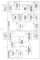
- 1 is a functional block diagram of a numerical control device and a robot control device according to a first embodiment.
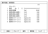
- FIG. FIG. 4 is a diagram illustrating an example of load information.
- FIG. 4 is a diagram showing load information of group 1 displayed when group 1 in FIG. 3 is selected.
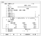
- FIG. 13 is a diagram illustrating an example of setting an operating area of a collaborative robot.
- FIG. 4 is a diagram showing an example of a numerical control program according to the first embodiment.
- 7 is a sequence diagram showing the flow of signals and information between the numerical control device and the robot control device when the numerical control program shown in FIG. 6 is executed.
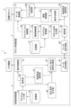
- FIG. 11 is a functional block diagram of a numerical control device and a robot control device according to a second embodiment.
- FIG. 11 is a diagram showing an example of a numerical control program according to the second embodiment.
- 10 is a sequence diagram showing the flow of signals and information between a numerical control device and a robot control device when the numerical control program shown in FIG. 9 is executed.
- Figure 1 is a schematic diagram of a numerical control system 1 according to this embodiment.
- the numerical control system 1 comprises a machine tool 2 that processes a workpiece (not shown), a numerical control device (CNC) 4 that controls the operation of the machine tool 2, a collaborative robot 3 provided near the machine tool 2, and a robot control device 5 that controls the operation of the collaborative robot 3.
- the numerical control system 1 controls the operation of the machine tool 2 and the collaborative robot 3 in a coordinated manner by using the numerical control device 4 and the robot control device 5 that are connected to each other so that they can communicate with each other.
- the machine tool 2 processes a workpiece (not shown) in response to a machine tool control signal sent from the numerical control device 4.
- the machine tool 2 is, for example, a lathe, a drill press, a milling machine, a grinding machine, a laser processing machine, an injection molding machine, etc., but is not limited to these.
- the collaborative robot 3 operates under the control of the robot control device 5, and performs a predetermined task on a workpiece being machined by, for example, the machine tool 2.
- the collaborative robot 3 is, for example, a multi-joint robot, and a tool 3b for gripping, machining, and inspecting the workpiece is attached to the arm tip 3a.
- the collaborative robot 3 will be described as a six-axis multi-joint robot, but this is not limited to this.
- the collaborative robot 3 will be described as a six-axis multi-joint robot, but the number of axes is not limited to this.
- the collaborative robot 3 has functions such as a contact stop function, an escape mode function, and an inversion operation function, and can work safely in collaboration with humans.
- the contact stop function is a function that immediately stops the collaborative robot 3 when it comes into contact with a human with a light force (for example, 10 to 20 N (i.e., 1 to 2 kgf)).
- the escape mode function is a function that allows the arm of the collaborative robot 3 to escape on each axis by the human pushing the arm.
- the inversion operation function is a function that reduces pinching by instantly inverting the arm when the collaborative robot 3 comes into contact with a hard object.
- the collaborative robot 3 is equipped with an external force detection sensor to detect external forces such as contact with a human.
- the external force detection sensor is, for example, a torque sensor or a force sensor. That is, the collaborative robot 3 detects contact with a human using the external force detection sensor, and the robot control device 5 stops the operation of the collaborative robot 3 according to the external force detected by the external force detection sensor. This allows the collaborative robot 3 to work safely in collaboration with humans.
- the numerical control device 4 and the robot control device 5 are computers that are each composed of hardware such as a calculation processing means such as a CPU (Central Processing Unit), auxiliary storage means such as an HDD (Hard Disk Drive) or SSD (Solid State Drive) that stores various computer programs, a main storage means such as a RAM (Random Access Memory) for storing data temporarily required for the calculation processing means to execute the computer programs, an operation means such as a keyboard that allows the operator to perform various operations, and a display means such as a display that displays various information to the operator.
- the numerical control device 4 and the robot control device 5 are capable of sending and receiving various signals to each other, for example, via Ethernet (registered trademark).
- Fig. 2 is a functional block diagram of the numerical control device 4 and the robot control device 5 according to the first embodiment. First, a detailed configuration of the numerical control device 4 will be described. As shown in Fig. 2, the numerical control device 4 realizes various functions such as a function to control the operation of the machine tool 2 and a function to generate a motion path of the control axis of the collaborative robot 3, by using the above hardware configuration.
- the numerical control device 4 uses a numerical control program to control the collaborative robot 3 via the robot control device 5. That is, the numerical control device 4 generates various commands for controlling the operation of the collaborative robot 3 and the tool 3b according to the numerical control program for the robot, and transmits them to the robot control device 5. More specifically, the numerical control device 4 includes a program input unit 41, an analysis unit 42, an operation control unit 43, a memory unit 44, a robot command signal generation unit 45, a load switching distance setting unit 46, a load setting selection unit 47, and a data transmission/reception unit 48.
- the program input unit 41 reads out a numerical control program for a robot, which is composed of multiple robot command blocks, from the memory unit 44 and inputs it sequentially to the analysis unit 42.
- the analysis unit 42 analyzes the command type based on the numerical control program input from the program input unit 41 for each command block, and outputs the analysis result to the operation control unit 43 and the robot command signal generation unit 45. More specifically, when the command type of the command block is a machine tool numerical control command for the machine tool 2, the analysis unit 42 transmits this machine tool numerical control command to the operation control unit 43. When the command type of the command block is a robot numerical control command for the collaborative robot 3, the analysis unit 42 outputs this robot numerical control command (hereinafter also referred to as a robot control command) to the robot command signal generation unit 45.
- a robot control command hereinafter also referred to as a robot control command
- the operation control unit 43 generates a machine tool control signal for controlling the operation of the machine tool 2 according to the analysis results sent from the analysis unit 42, and inputs the signal to the actuators that drive the various axes of the machine tool 2.
- the machine tool 2 operates according to the machine tool control signal input from the operation control unit 43, and machines a workpiece (not shown).
- the memory unit 44 stores, for example, a plurality of numerical control programs created based on operations by an operator. More specifically, the memory unit 44 stores numerical control programs that are composed of a plurality of command blocks for the machine tool 2 for controlling the operation of the machine tool 2, a plurality of command blocks for the collaborative robot 3 for controlling the operation of the collaborative robot 3, and the like.
- the numerical control programs stored in the memory unit 44 are written in a known programming language for controlling the operation of the machine tool 2, such as G-code or M-code.
- the memory unit 44 also stores, for example, machine coordinate values indicating the positions of various axes of the machine tool 2 operating under the above-mentioned numerical control program (i.e., the positions of the tool rest, table, etc. of the machine tool 2). These machine coordinate values are defined under a machine tool coordinate system that has as its origin a reference point determined at an arbitrary position on the machine tool 2 or in the vicinity of the machine tool 2. The machine coordinate values, which change sequentially under the numerical control program, are successively updated by a process not shown in the figures so that the latest values are stored in the memory unit 44.
- the memory unit 44 also stores, for example, robot coordinate values indicating the position and orientation of the control point (e.g., the arm tip 3a of the collaborative robot 3) of the collaborative robot 3 operating under the control of the robot control device 5, in other words, the position of each control axis of the collaborative robot 3.
- these robot coordinate values are defined under a robot coordinate system that is different from the machine tool coordinate system.
- the memory unit 44 is updated sequentially with the robot coordinate values obtained from the robot control device 5 by a process not shown in the figure so that the latest values of the robot coordinate values that change sequentially under the numerical control program are stored.
- the memory unit 44 also stores teaching positions, such as the start point and end point of the collaborative robot 3, input by the operator. Specifically, the memory unit 44 stores teaching positions of the collaborative robot 3 input from a teach pendant or the like, teaching positions input from a keyboard or the like, etc.
- the teaching positions of the collaborative robot 3 include robot coordinate values indicating the positions of each control axis of the collaborative robot 3, and these robot coordinate values are defined under a robot coordinate system that is different from the machine tool coordinate system.
- the robot command signal generation unit 45 generates a robot command signal for each robot command block based on the analysis results for each robot command block input from the analysis unit 42, and writes the generated robot command signal to the data transmission/reception unit 48.
- the robot command signal generation unit 45 generates a robot command signal for each robot command block based on the robot numerical control command as the analysis result input from the analysis unit 42, and writes the generated robot command signal to the data transmission/reception unit 48.
- the load switching distance setting unit 46 generates a signal for setting the load switching distance required to switch the load setting of the collaborative robot 3 in response to the robot control command analyzed by the analysis unit 42, and transmits the generated signal to the robot command signal generation unit 45.
- the load switching distance setting unit 46 when a load switching distance setting command is extracted from the robot control command analyzed by the analysis unit 42, the load switching distance setting unit 46 generates a signal for setting the load switching distance in accordance with the load switching distance setting command, and transmits the generated signal to the robot command signal generation unit 45. This allows the numerical control device 4 to notify the robot control device 5 of the load switching distance.
- the load setting selection unit 47 generates a signal for selecting a load setting for the collaborative robot 3 in accordance with the robot control command analyzed by the analysis unit 42, and transmits the generated signal to the robot command signal generation unit 45.
- the load setting selection unit 47 when a command to select a load setting is extracted from the robot control command analyzed by the analysis unit 42, the load setting selection unit 47 generates a signal for selecting a load setting for the collaborative robot 3 in response to the command to select a load setting, and transmits the generated signal to the robot command signal generation unit 45. This enables the numerical control device 4 to notify the robot control device 5 of a command to select a load setting.
- the robot command signal generator 45 also writes a robot command signal including a signal for setting the load switching distance described above or a signal for selecting a load setting to the data transmitter/receiver 48.
- the data transmission/reception unit 48 transmits and receives various data such as commands and robot coordinate values to and from the data transmission/reception unit 60 of the robot control device 5. Specifically, the data transmission/reception unit 48 transmits the robot command signal generated by the robot command signal generation unit 45 to the data transmission/reception unit 60 of the robot control device 5.
- the data transmission/reception unit 48 transmits a robot command signal including a signal for setting the load switching distance and a signal for selecting the load setting of the collaborative robot 3 to the robot control device 5 in response to the robot control command analyzed by the analysis unit 42.
- the above hardware configuration of the robot control device 5 realizes various functions such as a memory unit 51, an analysis unit 52, a robot command generation unit 53, a program management unit 54, a trajectory control unit 55, a kinematics control unit 56, a servo control unit 57, a load setting selection unit 58, a dynamics control unit 59, a data transmission/reception unit 60, a contact control unit 61, and a load switching distance setting unit 62.
- the robot control device 5 controls the operation of the collaborative robot 3 based on commands sent from the numerical control device 4.
- the memory unit 51 stores the robot program and various information for controlling the collaborative robot 3.
- the memory unit 51 also stores the load setting of the collaborative robot 3. Note that in this embodiment, the memory unit 51 is provided in the robot control device 5, but the memory unit 51 may be provided in the numerical control device 4, or in an external electronic device or external server outside the numerical control device 4 and the robot control device 5.
- the load setting of the collaborative robot 3 includes setting the operating area of the collaborative robot 3 where switching of the load setting is permitted, together with the load information.
- the load information includes the load setting number, the load weight, the position of the center of gravity of the load, the inertia of the load, etc. This load information is input in advance by the operator and stored in the memory unit 51.
- FIG. 3 is a diagram showing an example of load information.
- the load information is displayed on the display screen of the display device of the numerical control device 4.
- a group with a load weight of 50 kg is assigned multiple load setting numbers (No. 1 to 10).
- FIG. 4 shows the load information for group 1 that is displayed when group 1 in FIG. 3 is selected.
- the load information for group 1 stores the weight of the load, the position of the center of gravity of the load, and the inertia value of the load. In this way, the weight, the position of the center of gravity, and the inertia are associated with each load and stored in the memory unit 51.
- FIG. 5 is a diagram showing an example of setting the operating area of the collaborative robot 3.
- the robot control device 5 sets an operating area A1 of the collaborative robot 3 in which switching of the load setting is permitted.
- the operating area A1 is set between position 1 and position 2 in FIG. 5.
- the operating area A1 is set, for example, in the vicinity of the workpiece. This allows the robot control device 5 to switch the load setting of the collaborative robot 3 within the operating area A1.
- the collaborative robot 3 will not stop if it comes into contact with the user after the load setting is switched. Therefore, it is preferable to set the operating area A1 at a position that does not affect the work of the collaborative robot 3 or the user, such as near the work.
- the data transmission/reception unit 60 receives the robot command signal transmitted from the data transmission/reception unit 48 of the numerical control device 4.
- the data transmission/reception unit 60 also outputs the received robot command signal to the analysis unit 52 in sequence.
- the analysis unit 52 analyzes the robot command signal input from the data transmission/reception unit 60.
- the analysis unit 52 also outputs the analysis result to the robot command generation unit 53.
- the analysis unit 52 detects a signal for selecting a load setting for the collaborative robot 3 from the robot command signal, it notifies a load setting selection unit 58 (described below) of the load setting.
- the analysis unit 52 detects a signal for setting a load switching distance from the robot command signal, it notifies a load switching distance setting unit 62 (described below) of the load switching distance.
- the robot command generation unit 53 generates a robot command corresponding to the robot command signal based on the analysis result of the robot command signal input from the analysis unit 52.
- the robot command generation unit 53 outputs the generated robot command to the program management unit 54.
- the program management unit 54 When the program management unit 54 receives a robot command from the robot command generation unit 53, it executes the robot commands sequentially to generate an operation plan for the collaborative robot 3 according to the robot command signal, and outputs the operation plan to the trajectory control unit 55.
- the program management unit 54 adds the input block robot command to the robot program stored in the memory unit 51.
- a robot program corresponding to the robot command signal sent from the numerical control device 4 is generated and stored in the memory unit 51.
- the stored robot program is started and played when the program management unit 54 receives a robot program start command as a robot command.
- the trajectory control unit 55 calculates time series data of the control points of the collaborative robot 3 and outputs it to the kinematics control unit 56.
- the kinematics control unit 56 calculates the target angles of each joint of the collaborative robot 3 from the input time series data and inputs them to the servo control unit 57.
- the servo control unit 57 generates a robot control signal for the collaborative robot 3 by feedback controlling each servo motor of the collaborative robot 3 so that the target angle input from the kinematics control unit 56 is realized, and inputs the signal to the servo motor of the collaborative robot 3.
- the servo control unit 57 also generates a robot control signal that reflects the torque calculated by the dynamics control unit 59, which will be described later. This enables the robot control device 5 to control the collaborative robot 3 based on the load setting.
- the load setting selection unit 58 selects a load setting stored in the memory unit 51 in response to the robot command signal analyzed by the analysis unit 52, and notifies the dynamics control unit 59 of the selected load setting.
- the dynamics control unit 59 calculates the torque to be input to the collaborative robot 3 by inverse dynamics calculation based on the load setting selected by the load setting selection unit 58.
- the dynamics control unit 59 outputs the torque obtained by calculation to the servo control unit 57.
- the inverse dynamics calculation of the collaborative robot 3 is a method of calculating the input torque to each motor to realize the desired motion (time series data of the position, speed, and acceleration of each joint) calculated in the motion trajectory plan of the collaborative robot 3, taking into account the hand load, gravity, and the weight of the collaborative robot 3.
- Numerical calculation methods such as the calculated torque method and the Newton-Euler method have been disclosed as methods related to this type of inverse dynamics calculation (for example, JP 8-118275 A and JP 2015-58520 A).
- the load switching distance setting unit 62 sets the load switching distance in the contact control unit 61.
- the load switching distance of the collaborative robot 3 may be set according to at least one of the weight of the load and the inertia of the load.
- the load switching distance may be set for each coordinate axis direction of each coordinate axis of the collaborative robot 3.
- the contact control unit 61 controls the contact stop operation according to the result of external force detection by the external force detection sensor in the collaborative robot 3. After the load setting is switched by the load switching distance setting unit 62, the contact control unit 61 prohibits the contact stop operation while the collaborative robot 3 is moving within the load switching distance, i.e., until the collaborative robot 3 has completed moving the load switching distance.
- the contact stop operation refers to the operation of the collaborative robot 3 to stop the operation of the collaborative robot 3 in response to an external contact force.
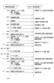
- FIG. 6 is a diagram showing an example of a numerical control program according to the first embodiment.
- FIG. 7 is a sequence diagram showing the flow of signals and information between the numerical control device 4 and the robot control device 5 when the numerical control program shown in FIG. 6 is executed.
- the numerical control program shown in FIG. 6 includes commands to select a load setting and set a load setting switching distance, as described above.
- the numerical control device 4 can notify the robot control device 5 of the center of gravity of the load, the position of the center of gravity of the load, and the inertia information of the load for load setting 1.
- the robot control device 5 starts to calculate the torque to be input to the collaborative robot 3 by inverse dynamics calculation based on the notified load setting 1.
- the load switching distance setting unit 46 generates a signal for setting the load switching distance in the + direction, and transmits the generated signal to the robot control device 5 via the robot command signal generating unit 45 and the data transmitting/receiving unit 48.
- the robot control device 5 updates the load switching distance in the + direction, and prohibits (disables) the contact stop operation until the collaborative robot 3 moves 5.0 mm in the +Z direction.
- the load switching distance setting unit 46 generates a signal for setting the load switching distance in the - direction, and transmits the generated signal to the robot control device 5 via the data transmission/reception unit 48.
- the robot control device 5 updates the load switching distance in the - direction, and the collaborative robot 3 enables the contact stop operation in the - direction.
- the robot control device 5 can disable the contact stop operation the next time the load setting is switched. Note that the robot control device 5 may disable the contact stop operation when the load setting is switched this time, rather than the next time.
- the robot control device 5 moves the collaborative robot 3 in a straight line to the specified position on the Cartesian coordinate system, and the collaborative robot 3 lifts the workpiece.
- the contact control unit 61 enables the contact stop operation.
- the load switching distance setting unit 46 generates a signal for setting the load switching distance in the +X direction, and transmits the generated signal to the robot control device 5 via the robot command signal generating unit 45 and the data transmitting/receiving unit 48.
- the robot control device 5 prohibits (disables) the contact stop operation until the collaborative robot 3 moves 5.0 mm in the +X direction.
- the load switching distance setting unit 46 generates a signal for setting the load switching distance in the - direction, and transmits the generated signal to the robot control device 5 via the robot command signal generating unit 45 and the data transmitting/receiving unit 48.
- the robot control device 5 updates the load switching distance in the - direction, and enables the contact stop operation in the - direction.
- the robot control device 5 can disable the contact stop operation the next time the load setting is switched. Note that the robot control device 5 may disable the contact stop operation when the load setting is switched this time, rather than the next time.
- the robot control device 5 moves the hand of the collaborative robot 3 in a straight line from the chuck position and retracts the hand of the collaborative robot 3 from the chuck position.
- the contact control unit 61 enables the contact stop operation when the collaborative robot 3 moves outside the load switching distance.
- "M30" is commanded and the numerical control program ends.
- the numerical control device 4 includes an analysis unit 42 that analyzes the robot control command in the numerical control program, a load switching distance setting unit 46 that generates a signal for setting a load switching distance required for switching the load setting of the collaborative robot 3 in accordance with the robot control command analyzed by the analysis unit 42, a load setting selection unit 47 that generates a signal for selecting a load setting for the collaborative robot 3 in accordance with the robot control command analyzed by the analysis unit 42, and a robot command signal generation unit 45 that generates a robot command signal including a signal for setting the load switching distance and a signal for selecting a load setting for the collaborative robot 3 in accordance with the robot control command analyzed by the analysis unit 42, and transmits the robot command signal to the robot control device 5.
- the robot control device 5 prohibits the collaborative robot 3 from performing a contact stop operation in which the collaborative robot 3 stops the operation of the collaborative robot 3 in response to an external contact force while the collaborative robot 3 is moving within the load switching distance.
- the numerical control device 4 prevents the collaborative robot 3 from making a contact stop within the specified load switching distance after changing the load setting, thereby preventing erroneous contact stops when the collaborative robot 3 acts on a workpiece, such as when the collaborative robot 3 picks up or places a workpiece.
- the load setting of the collaborative robot 3 also includes setting the operating area of the robot in which switching of the load setting is permitted, along with the load information.
- the numerical control device 4 can suitably switch the load setting and set the load setting distance.
- the load switching distance of the collaborative robot 3 may also be set according to at least one of the weight and inertia of the load.
- the load switching distance of the collaborative robot 3 may also be set for each coordinate axis direction of each coordinate axis of the collaborative robot 3.
- the numerical control device 4 can set a load setting distance suitable for the operation of the collaborative robot 3.
- the numerical control device 4 includes an analysis unit 42 that analyzes the robot control command in the numerical control program, a load switching distance setting unit 46 that generates a signal for setting a load switching distance required for switching the load setting of the collaborative robot 3 according to the robot control command analyzed by the analysis unit 42, a load setting selection unit 47 that generates a signal for selecting a load setting of the collaborative robot 3 according to the robot control command analyzed by the analysis unit 42, and a robot command signal generation unit 45 that generates a robot command signal including a signal for setting the load switching distance and a signal for selecting the load setting of the collaborative robot 3 according to the robot control command analyzed by the analysis unit 42, and transmits the robot command signal to the robot control device 5.
- an analysis unit 42 that analyzes the robot control command in the numerical control program
- a load switching distance setting unit 46 that generates a signal for setting a load switching distance required for switching the load setting of the collaborative robot 3 according to the robot control command analyzed by the analysis unit 42
- a load setting selection unit 47 that generates a
- the robot control device 5 further includes a load setting selection unit 58 that switches the load setting based on the robot command signal, a dynamics control unit that performs an inverse dynamics calculation of the collaborative robot 3 according to the load setting based on the robot command signal, a load switching distance setting unit 62 that sets the load switching distance based on the robot command signal, and a contact control unit 61 that prohibits the collaborative robot 3 from performing a contact stop operation that stops the operation of the collaborative robot 3 in response to an external contact force while the collaborative robot 3 is moving within the load switching distance after the load setting is switched in response to the notification of the load setting.
- a load setting selection unit 58 that switches the load setting based on the robot command signal
- a dynamics control unit that performs an inverse dynamics calculation of the collaborative robot 3 according to the load setting based on the robot command signal
- a load switching distance setting unit 62 that sets the load switching distance based on the robot command signal
- a contact control unit 61 that prohibits the collaborative robot 3 from performing a contact stop operation that stops the operation of
- the numerical control system 1 prevents the collaborative robot 3 from making a contact stop within the specified load switching distance after the load setting is changed, thereby preventing erroneous contact stops when the collaborative robot 3 acts on a workpiece, such as when the collaborative robot 3 picks up or places a workpiece.
- [Second embodiment] 8 is a functional block diagram of a numerical control device 4 and a robot control device 5 according to the second embodiment.
- the same components as those in the first embodiment are denoted by the same reference numerals, and the description thereof will be omitted or simplified.
- the numerical control device 4 and the robot control device 5 of the second embodiment are mainly different from the first embodiment in that they include a prohibition signal output unit 49 and an operation switching unit 63, and other configurations are the same as those of the first embodiment shown in FIGS. 2 and 3.
- the load setting selection unit 47 generates a signal for selecting a load setting for the collaborative robot 3 in accordance with the robot control command analyzed by the analysis unit 42, and transmits the generated signal to the robot command signal generation unit 45.
- the load setting selection unit 47 when a command to select a load setting is extracted from the robot control command analyzed by the analysis unit 42, the load setting selection unit 47 generates a signal for selecting a load setting for the collaborative robot 3 in response to the command to select a load setting, and transmits the generated signal to the robot command signal generation unit 45. This enables the numerical control device 4 to notify the robot control device 5 of a command to select a load setting.
- the prohibition signal output unit 49 generates a contact stop operation prohibition signal for prohibiting the contact stop operation of the collaborative robot 3 in response to the robot control command analyzed by the analysis unit 42, and transmits the generated contact stop operation prohibition signal to the robot command signal generation unit 45.
- the prohibition signal output unit 49 when a command to enable the contact stop operation prohibition signal is extracted from the robot control command analyzed by the analysis unit 42, the prohibition signal output unit 49 generates a contact stop operation prohibition signal in response to the command to enable the contact stop operation prohibition signal, and transmits the generated contact stop operation prohibition signal to the robot command signal generation unit 45. This enables the numerical control device 4 to notify the robot control device 5 of a command to prohibit (disable) the contact stop operation.
- the prohibition signal output unit 49 when a command to disable the contact stop operation prohibition signal is extracted from the robot control command analyzed by the analysis unit 42, the prohibition signal output unit 49 generates a signal to disable the contact stop operation prohibition signal in response to the command to disable the contact stop operation prohibition signal, and transmits the generated signal to the robot command signal generation unit 45. This allows the numerical control device 4 to notify the robot control device 5 of a command to enable the contact stop operation.
- the robot command signal generating unit 45 generates a robot command signal for each robot command block based on the analysis results for each robot command block input from the analyzing unit 42, and writes the generated robot command signal to the data transmitting/receiving unit 48.
- the robot command signal generating unit 45 also writes a robot command signal including a signal for selecting the load setting described above, a contact stop operation prohibition signal, or a signal for disabling the contact stop operation prohibition signal to the data transmitting/receiving unit 48.
- the data transmission/reception unit 48 transmits to the robot control device 5 a robot command signal including a contact stop operation prohibition signal, a signal for disabling the contact stop operation prohibition signal, and a signal for selecting the load setting of the collaborative robot 3 in response to the robot control command analyzed by the analysis unit 42.
- the operation switching unit 63 switches between enabling and disabling the contact stop operation in the contact control unit 61 according to the robot command signal analyzed by the analysis unit 52. Specifically, if a contact stop operation prohibition signal is extracted from the robot command signal, the operation switching unit 63 sets the contact stop operation to disabled after the next load setting is switched. Also, if a signal that disables (turns off) the contact stop operation prohibition signal is extracted from the robot command signal, the operation switching unit 63 sets the contact stop operation to enabled after the next load setting is switched.
- the contact control unit 61 prohibits the collaborative robot 3 from performing a contact stop operation in which the collaborative robot 3 stops operating in response to an external contact force in response to a contact stop operation prohibition signal.
- the contact control unit 61 sets the contact stop operation to disabled after the load setting is switched next time. Also, when the contact stop operation is enabled by the operation switching unit 63 in response to a signal that disables the contact stop operation prohibition signal, the contact control unit 61 sets the contact stop operation to enabled after the load setting is switched next time.
- FIG. 9 is a diagram showing an example of a numerical control program according to the second embodiment.
- FIG. 10 is a sequence diagram showing the flow of signals and information between the numerical control device 4 and the robot control device 5 when the numerical control program shown in FIG. 9 is executed.
- the numerical control program shown in FIG. 9 includes commands to select a load setting and output a contact stop operation prohibition signal, as described above.
- the numerical control device 4 can notify the robot control device 5 of the center of gravity of the load, the position of the center of gravity of the load, and the inertia information of the load for load setting 1.
- the robot control device 5 starts to calculate the torque to be input to the collaborative robot 3 by inverse dynamics calculation based on the notified load setting 1.
- the prohibition signal output unit 49 generates a contact stop operation prohibition signal for prohibiting the contact stop operation of the collaborative robot 3, and transmits the generated contact stop operation prohibition signal to the robot control device 5 via the robot command signal generation unit 45 and the data transmission/reception unit 48.
- the robot control device 5 can disable the contact stop operation in response to the contact stop operation prohibition signal the next time the load setting is switched.
- load setting 2 corresponding to the grasped workpiece, which has been stored in advance in memory unit 51, is selected.
- the selected load setting 2 is updated by load setting selection unit 58 from load setting 1 that had been set up until then to the newly notified load setting 2.
- dynamics control unit 59 calculates inverse dynamics based on the updated load setting 2, and collaborative robot 3 is controlled according to a robot control command that reflects the calculated input torque.
- the contact control unit 61 since the contact control unit 61 has switched load setting 1 to load setting 2, it disables the contact stop operation of collaborative robot 3.
- the robot control device 5 moves the collaborative robot 3 in a straight line to the specified position (work position) on the Cartesian coordinate system and lifts the work.
- the prohibition signal output unit 49 generates a contact stop operation prohibition signal for prohibiting the contact stop operation of the collaborative robot 3, and transmits a signal for disabling (turning off) the generated contact stop operation prohibition signal to the robot control device 5 via the robot command signal generation unit 45 and the data transmission/reception unit 48. This allows the robot control device 5 to enable the contact stop operation in response to the signal for disabling the contact stop operation prohibition signal.
- the prohibition signal output unit 49 generates a contact stop operation prohibition signal for prohibiting the contact stop operation of the collaborative robot 3, and transmits the generated contact stop operation prohibition signal to the robot control device 5 via the robot command signal generation unit 45 and the data transmission/reception unit 48.
- the robot control device 5 can disable the contact stop operation in response to the contact stop operation prohibition signal the next time the load setting is switched.
- load setting 1 corresponding to the grasped workpiece, which has been pre-stored in memory unit 51, is selected.
- the selected load setting 2 is updated by load setting selection unit 58 from the already set load setting 2 to the newly notified load setting 1.
- dynamics control unit 59 calculates inverse dynamics based on the updated load setting 1, and collaborative robot 3 is controlled according to the robot control command reflecting the calculated input torque.
- the contact control unit 61 since the contact control unit 61 has switched load setting 2 to load setting 1, it disables the contact stop operation of collaborative robot 3.
- the robot control device 5 moves the collaborative robot 3 in a straight line from the chuck position and moves the collaborative robot 3 away from the chuck position.
- the numerical control device 4 includes an analysis unit 42 that analyzes the robot control command in the numerical control program, a prohibition signal output unit 49 that generates a contact stop operation prohibition signal for prohibiting the contact stop operation of the collaborative robot 3 in accordance with the robot control command analyzed by the analysis unit 42, a load setting selection unit 47 that generates a signal for selecting a load setting for the collaborative robot 3 in accordance with the robot control command analyzed by the analysis unit 42, and a robot command signal generation unit 45 that generates a robot command signal including the contact stop operation prohibition signal and a signal for selecting a load setting for the collaborative robot 3 in accordance with the robot control command analyzed by the analysis unit 42 and transmits the robot command signal to the robot control device 5, and after switching the load setting, the robot control device 5 prohibits a contact stop operation in which the robot command signal generation unit 45 stops the operation of the robot command signal generation unit 45 in accordance with an external contact force in response to the contact stop operation prohibition signal.
- the numerical control device 4 prevents the collaborative robot 3 from making a contact stop within the specified load switching distance after changing the load setting, thereby preventing erroneous contact stops when the collaborative robot 3 acts on a workpiece, such as when the collaborative robot 3 picks up or places a workpiece.
- the numerical control device 4 includes an analysis unit 42 that analyzes the robot control command in the numerical control program, a prohibition signal output unit 49 that generates a contact stop operation prohibition signal for prohibiting the contact stop operation of the collaborative robot 3 in accordance with the robot control command analyzed by the analysis unit 42, a load setting selection unit 47 that generates a signal for selecting a load setting for the collaborative robot 3 in accordance with the robot control command analyzed by the analysis unit 42, and a robot command signal generation unit 45 that generates a robot command signal including the contact stop operation prohibition signal and a signal for selecting a load setting for the collaborative robot 3 in accordance with the robot control command analyzed by the analysis unit 42, and transmits the robot command signal to the robot control device 5.
- an analysis unit 42 that analyzes the robot control command in the numerical control program
- a prohibition signal output unit 49 that generates a contact stop operation prohibition signal for prohibiting the contact stop operation of the collaborative robot 3 in accordance with the robot control command analyzed by the analysis unit 42
- a load setting selection unit 47 that generates a
- the robot control device 5 further includes a load setting selection unit 58 that switches the load setting based on the robot command signal, a dynamics control unit 59 that performs inverse dynamics calculations of the collaborative robot 3 according to the load setting based on the robot command signal, and a contact control unit 61 that prohibits a contact stop operation in which the collaborative robot 3 stops the operation of the collaborative robot 3 in response to an external contact force in response to a contact stop operation prohibition signal after the load setting has been switched based on the notification of the load setting.
- a load setting selection unit 58 that switches the load setting based on the robot command signal
- a dynamics control unit 59 that performs inverse dynamics calculations of the collaborative robot 3 according to the load setting based on the robot command signal
- a contact control unit 61 that prohibits a contact stop operation in which the collaborative robot 3 stops the operation of the collaborative robot 3 in response to an external contact force in response to a contact stop operation prohibition signal after the load setting has been switched based on the notification of the load setting.
- the numerical control system 1 prevents the collaborative robot 3 from making a contact stop within the specified load switching distance after the load setting is changed, thereby preventing erroneous contact stops when the collaborative robot 3 acts on a workpiece, such as when the collaborative robot 3 picks up or places a workpiece.
- the above-mentioned numerical control system 1 can be realized by hardware, software, or a combination of these. Furthermore, the control method performed by the above-mentioned numerical control system 1 can also be realized by hardware, software, or a combination of these.
- being realized by software means being realized by a computer reading and executing a program.
- Non-transitory computer readable media include various types of tangible storage media.
- Examples of non-transitory computer readable media include magnetic recording media (e.g., hard disk drives), magneto-optical recording media (e.g., magneto-optical disks), CD-ROMs (Read Only Memory), CD-Rs, CD-R/Ws, and semiconductor memories (e.g., mask ROMs, PROMs (Programmable ROMs), EPROMs (Erasable PROMs), flash ROMs, and RAMs (random access memory)).
- a numerical control device (4) that controls a robot (3) via a robot control device (5) using a numerical control program, an analysis unit (42) that analyzes a robot control command in the numerical control program; a load switching distance setting unit (46) that generates a signal for setting a load switching distance required for switching a load setting of the robot in response to the robot control command analyzed by the analysis unit; a load setting selection unit (47) that generates a signal for selecting a load setting of the robot in response to the robot control command analyzed by the analysis unit; a robot command signal generation unit (45) that generates a robot command signal including a signal for setting the load switching distance and a signal for selecting a load setting for the robot in response to the robot control command analyzed by the analysis unit, and transmits the robot command signal to the robot control device; Equipped with After the load setting is switched, the robot control device (5) prohibits the robot from performing a contact stop operation in which the robot stops operation in response to an
- Numerical control device (4) The numerical control device (4) according to appendix 1, wherein the load setting of the robot includes setting, together with the load information, an operating area of the robot in which switching of the load setting is permitted.
- Appendix 3) The numerical control device (4) according to appendix 1, wherein a load switching distance of the robot is set according to at least one of a weight and an inertia of a load.
- Appendix 4) The numerical control device (4) according to appendix 1, wherein a load switching distance of the robot is set for each coordinate axis direction of each coordinate axis of the robot.
- Appendix 5 2. The numerical control device according to claim 1, wherein the robot is a collaborative robot that detects contact with a human and stops moving.
- the numerical control device (4) comprises: an analysis unit (42) that analyzes a robot control command in the numerical control program; a load switching distance setting unit (46) that generates a signal for setting a load switching distance required for switching a load setting of the robot in response to the robot control command analyzed by the analysis unit; a load setting selection unit (47) that generates a signal for selecting a load setting of the robot in response to the robot control command analyzed by the analysis unit; a robot command signal generation unit (45) that generates a robot command signal including a signal for setting the load switching distance and a signal for selecting a load setting for the robot in response to the robot control command analyzed by the analysis unit, and transmits the robot command signal to the robot control device; Equipped with The robot control device (5) a robot side load setting selection unit (58) that switches the load setting based on the robot command signal; a dynamics control
- Numerical control device (4) The numerical control device (4) described in Appendix 11, wherein the load setting of the robot includes setting, together with the load information, an operating area of the robot in which switching of the load setting is permitted.
- Appendix 13 12. The numerical control device according to claim 11, wherein the robot is a collaborative robot that detects contact with a human and stops its operation.
- the numerical control device (4) comprises: an analysis unit (42) that analyzes a robot control command in the numerical control program; a prohibition signal output unit (49) that generates a contact stop operation prohibition signal for prohibiting a contact stop operation of the robot in response to the robot control command analyzed by the analysis unit; a load setting selection unit (47) that generates a signal for selecting a load setting of the robot in response to the robot control command analyzed by the analysis unit; a robot command signal generation unit (45) that generates a robot command signal including the contact stop operation prohibition signal and a signal for selecting a load setting of the robot in response to the robot control command analyzed by the analysis unit, and transmits the robot command signal to the robot control device; Equipped with The robot control device (5) a robot side load setting selection unit (58) that switches the load setting based on the robot command signal; a dynamics control unit (59) that performs
Landscapes
- Engineering & Computer Science (AREA)
- Robotics (AREA)
- Mechanical Engineering (AREA)
- Numerical Control (AREA)
- Manipulator (AREA)
Abstract
Description
図2は、第1実施形態に係る数値制御装置4及びロボット制御装置5の機能ブロック図である。先ず、数値制御装置4の詳細な構成について説明する。図2に示すように数値制御装置4は、上記ハードウェア構成によって、工作機械2の動作を制御する機能、協働ロボット3の制御軸の動作経路を生成する機能等のような各種機能を実現する。
図8は、第2実施形態に係る数値制御装置4及びロボット制御装置5の機能ブロック図である。なお、第2実施形態の説明にあたっては、第1実施形態と同一の構成要件については同一符号を付し、その説明を省略もしくは簡略化する。第2実施形態の数値制御装置4及びロボット制御装置5は、禁止信号出力部49及び動作切替部63を備える点が第1実施形態とは主として異なり、他の構成は、図2及び3に示される第1実施形態と同様の構成を備える。
(付記1)
数値制御プログラムを用いてロボット制御装置(5)を介してロボット(3)を制御する数値制御装置(4)であって、
前記数値制御プログラム中のロボット制御指令を解析する解析部(42)と、
前記解析部により解析した前記ロボット制御指令に応じて、前記ロボットの負荷設定の切替に必要な負荷切替距離を設定するための信号を生成する負荷切替距離設定部(46)と、
前記解析部により解析した前記ロボット制御指令に応じて、前記ロボットの負荷設定を選択するための信号を生成する負荷設定選択部(47)と、
前記解析部により解析した前記ロボット制御指令に応じて、前記負荷切替距離を設定するための信号及び前記ロボットの負荷設定を選択するための信号を含むロボット指令信号を生成し、前記ロボット指令信号を前記ロボット制御装置へ送信するロボット指令信号生成部(45)と、
を備え、
前記負荷設定の切り替え後、前記ロボット制御装置(5)は、前記ロボットが前記負荷切替距離内を移動している間、前記ロボットが外部からの接触力に応じて前記ロボットの動作を停止する接触停止動作を禁止させる、
数値制御装置(4)。
(付記2)
前記ロボットの負荷設定は、負荷情報と共に、前記負荷設定の切替を許可する前記ロボットの動作領域を設定することを含む、付記1に記載の数値制御装置(4)。
(付記3)
前記ロボットの負荷切替距離は、負荷の重量及びイナーシャの少なくとも1つに応じて設定される、付記1に記載の数値制御装置(4)。
(付記4)
前記ロボットの負荷切替距離は、前記ロボットの各座標軸の座標軸方向毎に設定される、付記1に記載の数値制御装置(4)。
(付記5)
前記ロボットは、人との接触を検知して動作を停止する協働ロボットである、付記1に記載の数値制御装置。
(付記6)
数値制御装置(4)の数値制御プログラムを用いてロボット制御装置(5)を介してロボット(3)を制御する数値制御システム(1)であって、
前記数値制御装置(4)は、
前記数値制御プログラム中のロボット制御指令を解析する解析部(42)と、
前記解析部により解析した前記ロボット制御指令に応じて、前記ロボットの負荷設定の切替に必要な負荷切替距離を設定するための信号を生成する負荷切替距離設定部(46)と、
前記解析部により解析した前記ロボット制御指令に応じて、前記ロボットの負荷設定を選択するための信号を生成する負荷設定選択部(47)と、
前記解析部により解析した前記ロボット制御指令に応じて、前記負荷切替距離を設定するための信号及び前記ロボットの負荷設定を選択するための信号を含むロボット指令信号を生成し、前記ロボット指令信号を前記ロボット制御装置へ送信するロボット指令信号生成部(45)と、
を備え、
前記ロボット制御装置(5)は、
前記ロボット指令信号に基づいて、前記負荷設定を切り替えるロボット側負荷設定選択部(58)と、
前記ロボット指令信号に基づいて、前記負荷設定に応じて前記ロボットの逆動力学計算を行うダイナミクス制御部(59)と、
前記ロボット指令信号に基づいて、前記負荷切替距離を設定するロボット側負荷切替距離設定部(62)と、
前記負荷設定の通知による前記負荷設定の切替後、前記ロボットが前記負荷切替距離内を移動している間、前記ロボットが外部からの接触力に応じて前記ロボットの動作を停止する接触停止動作を禁止させる接触制御部(61)と、
を備える数値制御システム(1)。
(付記7)
前記ロボットの負荷設定は、負荷情報と共に、前記負荷設定の切替を許可する前記ロボットの動作領域を設定することを含む、付記6に記載の数値制御システム(1)。
(付記8)
前記ロボットの負荷切替距離は、負荷の重量及びイナーシャの少なくとも1つに応じて設定される、付記6に記載の数値制御システム(1)。
(付記9)
前記ロボットの負荷切替距離は、前記ロボットの各座標軸の座標軸方向毎に設定される、付記6に記載の数値制御システム(1)。
(付記10)
前記ロボットは、人との接触を検知して動作を停止する協働ロボットである、付記6に記載の数値制御システム。
(付記11)
数値制御プログラムを用いてロボット制御装置(5)を介してロボットを制御する数値制御装置(4)であって、
前記数値制御プログラム中のロボット制御指令を解析する解析部(42)と、
前記解析部により解析した前記ロボット制御指令に応じて、前記ロボットの接触停止動作を禁止するための接触停止動作禁止信号を生成する禁止信号出力部(49)と、
前記解析部により解析した前記ロボット制御指令に応じて、前記ロボットの負荷設定を選択するための信号を生成する負荷設定選択部(47)と、
前記解析部により解析した前記ロボット制御指令に応じて、前記接触停止動作禁止信号及び前記ロボットの負荷設定を選択するための信号を含むロボット指令信号を生成し、前記ロボット指令信号を前記ロボット制御装置へ送信するロボット指令信号生成部(45)と、
を備え、
前記負荷設定の切り替え後、前記ロボット制御装置(5)は、前記接触停止動作禁止信号に応じて、前記ロボットが外部からの接触力に応じて前記ロボットの動作を停止する接触停止動作を禁止させる、
数値制御装置(4)。
(付記12)
前記ロボットの負荷設定は、負荷情報と共に、前記負荷設定の切替を許可する前記ロボットの動作領域を設定することを含む、付記11に記載の数値制御装置(4)。
(付記13)
前記ロボットは、人との接触を検知して動作を停止する協働ロボットである、付記11に記載の数値制御装置。
(付記14)
数値制御装置(4)の数値制御プログラムを用いてロボット制御装置(5)を介してロボットを制御する数値制御システム(1)であって、
前記数値制御装置(4)は、
前記数値制御プログラム中のロボット制御指令を解析する解析部(42)と、
前記解析部により解析した前記ロボット制御指令に応じて、前記ロボットの接触停止動作を禁止するための接触停止動作禁止信号を生成する禁止信号出力部(49)と、
前記解析部により解析した前記ロボット制御指令に応じて、前記ロボットの負荷設定を選択するための信号を生成する負荷設定選択部(47)と、
前記解析部により解析した前記ロボット制御指令に応じて、前記接触停止動作禁止信号及び前記ロボットの負荷設定を選択するための信号を含むロボット指令信号を生成し、前記ロボット指令信号を前記ロボット制御装置へ送信するロボット指令信号生成部(45)と、
を備え、
前記ロボット制御装置(5)は、
前記ロボット指令信号に基づいて、前記負荷設定を切り替えるロボット側負荷設定選択部(58)と、
前記ロボット指令信号に基づいて、前記負荷設定に応じて前記ロボットの逆動力学計算を行うダイナミクス制御部(59)と、
前記負荷設定の通知による前記負荷設定の切替後、前記接触停止動作禁止信号に応じて、前記ロボットが外部からの接触力に応じて前記ロボットの動作を停止する接触停止動作を禁止させる接触制御部(61)と、
を備える数値制御システム(1)。
(付記15)
前記ロボットの負荷設定は、負荷情報と共に、前記負荷設定の切替を許可する前記ロボットの動作領域を設定することを含む、付記14に記載の数値制御システム。
(付記16)
前記ロボットは、人との接触を検知して動作を停止する協働ロボットである、付記14に記載の数値制御システム。
2 工作機械
3 協働ロボット
4 数値制御装置
5 ロボット制御装置
41 プログラム入力部
42 解析部
43 動作制御部
44 記憶部
45 ロボット指令信号生成部
46 負荷切替距離設定部
47 負荷設定選択部
48 データ送受信部
49 禁止信号出力部
51 記憶部
52 解析部
53 ロボット命令生成部
54 プログラム管理部
55 軌跡制御部
56 キネマティクス制御部
57 サーボ制御部
58 負荷設定選択部
59 ダイナミクス制御部
60 データ送受信部
61 接触制御部
62 負荷切替距離設定部
63 動作切替部
Claims (16)
- 数値制御プログラムを用いてロボット制御装置を介してロボットを制御する数値制御装置であって、
前記数値制御プログラム中のロボット制御指令を解析する解析部と、
前記解析部により解析した前記ロボット制御指令に応じて、前記ロボットの負荷設定の切替に必要な負荷切替距離を設定するための信号を生成する負荷切替距離設定部と、
前記解析部により解析した前記ロボット制御指令に応じて、前記ロボットの負荷設定を選択するための信号を生成する負荷設定選択部と、
前記解析部により解析した前記ロボット制御指令に応じて、前記負荷切替距離を設定するための信号及び前記ロボットの負荷設定を選択するための信号を含むロボット指令信号を生成し、前記ロボット指令信号を前記ロボット制御装置へ送信するロボット指令信号生成部と、
を備え、
前記負荷設定の切り替え後、前記ロボット制御装置は、前記ロボットが前記負荷切替距離内を移動している間、前記ロボットが外部からの接触力に応じて前記ロボットの動作を停止する接触停止動作を禁止させる、
数値制御装置。 - 前記ロボットの負荷設定は、負荷情報と共に、前記負荷設定の切替を許可する前記ロボットの動作領域を設定することを含む、請求項1に記載の数値制御装置。
- 前記ロボットの負荷切替距離は、負荷の重量及びイナーシャの少なくとも1つに応じて設定される、請求項1に記載の数値制御装置。
- 前記ロボットの負荷切替距離は、前記ロボットの各座標軸の座標軸方向毎に設定される、請求項1に記載の数値制御装置。
- 前記ロボットは、人との接触を検知して動作を停止する協働ロボットである、請求項1に記載の数値制御装置。
- 数値制御装置の数値制御プログラムを用いてロボット制御装置を介してロボットを制御する数値制御システムであって、
前記数値制御装置は、
前記数値制御プログラム中のロボット制御指令を解析する解析部と、
前記解析部により解析した前記ロボット制御指令に応じて、前記ロボットの負荷設定の切替に必要な負荷切替距離を設定するための信号を生成する負荷切替距離設定部と、
前記解析部により解析した前記ロボット制御指令に応じて、前記ロボットの負荷設定を選択するための信号を生成する負荷設定選択部と、
前記解析部により解析した前記ロボット制御指令に応じて、前記負荷切替距離を設定するための信号及び前記ロボットの負荷設定を選択するための信号を含むロボット指令信号を生成し、前記ロボット指令信号を前記ロボット制御装置へ送信するロボット指令信号生成部と、
を備え、
前記ロボット制御装置は、
前記ロボット指令信号に基づいて、前記負荷設定を切り替えるロボット側負荷設定選択部と、
前記ロボット指令信号に基づいて、前記負荷設定に応じて前記ロボットの逆動力学計算を行うダイナミクス制御部と、
前記ロボット指令信号に基づいて、前記負荷切替距離を設定するロボット側負荷切替距離設定部と、
前記負荷設定の通知による前記負荷設定の切替後、前記ロボットが前記負荷切替距離内を移動している間、前記ロボットが外部からの接触力に応じて前記ロボットの動作を停止する接触停止動作を禁止させる接触制御部と、
を備える数値制御システム。 - 前記ロボットの負荷設定は、負荷情報と共に、前記負荷設定の切替を許可する前記ロボットの動作領域を設定することを含む、請求項6に記載の数値制御システム。
- 前記ロボットの負荷切替距離は、負荷の重量及びイナーシャの少なくとも1つに応じて設定される、請求項6に記載の数値制御システム。
- 前記ロボットの負荷切替距離は、前記ロボットの各座標軸の座標軸方向毎に設定される、請求項6に記載の数値制御システム。
- 前記ロボットは、人との接触を検知して動作を停止する協働ロボットである、請求項6に記載の数値制御システム。
- 数値制御プログラムを用いてロボット制御装置を介してロボットを制御する数値制御装置であって、
前記数値制御プログラム中のロボット制御指令を解析する解析部と、
前記解析部により解析した前記ロボット制御指令に応じて、前記ロボットの接触停止動作を禁止するための接触停止動作禁止信号を生成する禁止信号出力部と、
前記解析部により解析した前記ロボット制御指令に応じて、前記ロボットの負荷設定を選択するための信号を生成する負荷設定選択部と、
前記解析部により解析した前記ロボット制御指令に応じて、前記接触停止動作禁止信号及び前記ロボットの負荷設定を選択するための信号を含むロボット指令信号を生成し、前記ロボット指令信号を前記ロボット制御装置へ送信するロボット指令信号生成部と、
を備え、
前記負荷設定の切り替え後、前記ロボット制御装置は、前記接触停止動作禁止信号に応じて、前記ロボットが外部からの接触力に応じて前記ロボットの動作を停止する接触停止動作を禁止させる、
数値制御装置。 - 前記ロボットの負荷設定は、負荷情報と共に、前記負荷設定の切替を許可する前記ロボットの動作領域を設定することを含む、請求項11に記載の数値制御装置。
- 前記ロボットは、人との接触を検知して動作を停止する協働ロボットである、請求項11に記載の数値制御装置。
- 数値制御装置の数値制御プログラムを用いてロボット制御装置を介してロボットを制御する数値制御システムであって、
前記数値制御装置は、
前記数値制御プログラム中のロボット制御指令を解析する解析部と、
前記解析部により解析した前記ロボット制御指令に応じて、前記ロボットの接触停止動作を禁止するための接触停止動作禁止信号を生成する禁止信号出力部と、
前記解析部により解析した前記ロボット制御指令に応じて、前記ロボットの負荷設定を選択するための信号を生成する負荷設定選択部と、
前記解析部により解析した前記ロボット制御指令に応じて、前記接触停止動作禁止信号及び前記ロボットの負荷設定を選択するための信号を含むロボット指令信号を生成し、前記ロボット指令信号を前記ロボット制御装置へ送信するロボット指令信号生成部と、
を備え、
前記ロボット制御装置は、
前記ロボット指令信号に基づいて、前記負荷設定を切り替えるロボット側負荷設定選択部と、
前記ロボット指令信号に基づいて、前記負荷設定に応じて前記ロボットの逆動力学計算を行うダイナミクス制御部と、
前記負荷設定の通知による前記負荷設定の切替後、前記接触停止動作禁止信号に応じて、前記ロボットが外部からの接触力に応じて前記ロボットの動作を停止する接触停止動作を禁止させる接触制御部と、
を備える数値制御システム。 - 前記ロボットの負荷設定は、負荷情報と共に、前記負荷設定の切替を許可する前記ロボットの動作領域を設定することを含む、請求項14に記載の数値制御システム。
- 前記ロボットは、人との接触を検知して動作を停止する協働ロボットである、請求項14に記載の数値制御システム。
Priority Applications (5)
| Application Number | Priority Date | Filing Date | Title |
|---|---|---|---|
| DE112022007698.4T DE112022007698T5 (de) | 2022-11-07 | 2022-11-07 | Numerische Steuerungsvorrichtung und numerisches Steuerungssystem |
| CN202280101462.5A CN120129877A (zh) | 2022-11-07 | 2022-11-07 | 数值控制装置以及数值控制系统 |
| JP2023504082A JP7288157B1 (ja) | 2022-11-07 | 2022-11-07 | 数値制御装置及び数値制御システム |
| PCT/JP2022/041386 WO2024100718A1 (ja) | 2022-11-07 | 2022-11-07 | 数値制御装置及び数値制御システム |
| TW112139550A TW202419995A (zh) | 2022-11-07 | 2023-10-17 | 數值控制裝置及數值控制系統 |
Applications Claiming Priority (1)
| Application Number | Priority Date | Filing Date | Title |
|---|---|---|---|
| PCT/JP2022/041386 WO2024100718A1 (ja) | 2022-11-07 | 2022-11-07 | 数値制御装置及び数値制御システム |
Publications (1)
| Publication Number | Publication Date |
|---|---|
| WO2024100718A1 true WO2024100718A1 (ja) | 2024-05-16 |
Family
ID=86611017
Family Applications (1)
| Application Number | Title | Priority Date | Filing Date |
|---|---|---|---|
| PCT/JP2022/041386 Ceased WO2024100718A1 (ja) | 2022-11-07 | 2022-11-07 | 数値制御装置及び数値制御システム |
Country Status (5)
| Country | Link |
|---|---|
| JP (1) | JP7288157B1 (ja) |
| CN (1) | CN120129877A (ja) |
| DE (1) | DE112022007698T5 (ja) |
| TW (1) | TW202419995A (ja) |
| WO (1) | WO2024100718A1 (ja) |
Cited By (1)
| Publication number | Priority date | Publication date | Assignee | Title |
|---|---|---|---|---|
| JP7735600B1 (ja) * | 2025-02-12 | 2025-09-08 | Dmg森精機株式会社 | 情報処理装置、ロボットシステム、および負荷設定の支援方法 |
Citations (5)
| Publication number | Priority date | Publication date | Assignee | Title |
|---|---|---|---|---|
| JP2008183680A (ja) * | 2007-01-31 | 2008-08-14 | Yaskawa Electric Corp | 負荷機械の制御装置とその衝突検出しきい値更新方法 |
| JP2009050958A (ja) * | 2007-08-27 | 2009-03-12 | Fanuc Ltd | 停止監視機能を備えたロボット制御装置 |
| JP6647472B1 (ja) * | 2019-01-09 | 2020-02-14 | 三菱電機株式会社 | 数値制御装置および数値制御方法 |
| WO2020045483A1 (ja) * | 2018-08-30 | 2020-03-05 | 株式会社不二越 | ロボット制御装置 |
| WO2022224425A1 (ja) * | 2021-04-23 | 2022-10-27 | ファナック株式会社 | 数値制御装置及び数値制御システム |
-
2022
- 2022-11-07 CN CN202280101462.5A patent/CN120129877A/zh active Pending
- 2022-11-07 DE DE112022007698.4T patent/DE112022007698T5/de active Pending
- 2022-11-07 JP JP2023504082A patent/JP7288157B1/ja active Active
- 2022-11-07 WO PCT/JP2022/041386 patent/WO2024100718A1/ja not_active Ceased
-
2023
- 2023-10-17 TW TW112139550A patent/TW202419995A/zh unknown
Patent Citations (5)
| Publication number | Priority date | Publication date | Assignee | Title |
|---|---|---|---|---|
| JP2008183680A (ja) * | 2007-01-31 | 2008-08-14 | Yaskawa Electric Corp | 負荷機械の制御装置とその衝突検出しきい値更新方法 |
| JP2009050958A (ja) * | 2007-08-27 | 2009-03-12 | Fanuc Ltd | 停止監視機能を備えたロボット制御装置 |
| WO2020045483A1 (ja) * | 2018-08-30 | 2020-03-05 | 株式会社不二越 | ロボット制御装置 |
| JP6647472B1 (ja) * | 2019-01-09 | 2020-02-14 | 三菱電機株式会社 | 数値制御装置および数値制御方法 |
| WO2022224425A1 (ja) * | 2021-04-23 | 2022-10-27 | ファナック株式会社 | 数値制御装置及び数値制御システム |
Cited By (1)
| Publication number | Priority date | Publication date | Assignee | Title |
|---|---|---|---|---|
| JP7735600B1 (ja) * | 2025-02-12 | 2025-09-08 | Dmg森精機株式会社 | 情報処理装置、ロボットシステム、および負荷設定の支援方法 |
Also Published As
| Publication number | Publication date |
|---|---|
| TW202419995A (zh) | 2024-05-16 |
| DE112022007698T5 (de) | 2025-07-17 |
| CN120129877A (zh) | 2025-06-10 |
| JP7288157B1 (ja) | 2023-06-06 |
| JPWO2024100718A1 (ja) | 2024-05-16 |
Similar Documents
| Publication | Publication Date | Title |
|---|---|---|
| JP7590554B2 (ja) | 数値制御装置及び数値制御システム | |
| JP7288158B1 (ja) | 数値制御装置 | |
| WO2024100718A1 (ja) | 数値制御装置及び数値制御システム | |
| JP7633371B2 (ja) | 指令生成装置及びコンピュータプログラム | |
| WO2024161517A1 (ja) | 数値制御装置及び数値制御システム | |
| WO2024116221A1 (ja) | 数値制御装置及び数値制御システム | |
| JP7332822B1 (ja) | 数値制御装置及び数値制御システム | |
| TWI919126B (zh) | 數值控制裝置及數值控制系統 | |
| JP7260728B1 (ja) | 数値制御装置及び数値制御システム | |
| JP7614220B2 (ja) | 数値制御装置、及び数値制御システム | |
| WO2024100720A1 (ja) | 数値制御装置及び数値制御システム | |
| TWI917819B (zh) | 數值控制裝置及數值控制系統 | |
| US20230249337A1 (en) | Numerical control system | |
| WO2025046677A1 (ja) | 数値制御装置及び数値制御システム | |
| WO2024116223A1 (ja) | ロボット制御装置 | |
| JP7695336B2 (ja) | ロボット制御装置、ロボット制御システム、及びコンピュータプログラム | |
| US20240160181A1 (en) | Motion-path generation device, numerical control device, numerical control system, and non-transitory computer-readable medium storing computer program | |
| WO2025062629A1 (ja) | 数値制御装置及び数値制御システム | |
| WO2024166216A1 (ja) | 数値制御装置及び数値制御システム | |
| WO2022004647A1 (ja) | 数値制御システム |
Legal Events
| Date | Code | Title | Description |
|---|---|---|---|
| WWE | Wipo information: entry into national phase |
Ref document number: 2023504082 Country of ref document: JP |
|
| 121 | Ep: the epo has been informed by wipo that ep was designated in this application |
Ref document number: 22965045 Country of ref document: EP Kind code of ref document: A1 |
|
| WWE | Wipo information: entry into national phase |
Ref document number: 112022007698 Country of ref document: DE |
|
| WWE | Wipo information: entry into national phase |
Ref document number: 202280101462.5 Country of ref document: CN |
|
| WWP | Wipo information: published in national office |
Ref document number: 202280101462.5 Country of ref document: CN |
|
| WWP | Wipo information: published in national office |
Ref document number: 112022007698 Country of ref document: DE |
|
| 122 | Ep: pct application non-entry in european phase |
Ref document number: 22965045 Country of ref document: EP Kind code of ref document: A1 |