WO2024095607A1 - 通信端末制御装置、通信端末制御方法、およびプログラム - Google Patents
通信端末制御装置、通信端末制御方法、およびプログラム Download PDFInfo
- Publication number
- WO2024095607A1 WO2024095607A1 PCT/JP2023/032781 JP2023032781W WO2024095607A1 WO 2024095607 A1 WO2024095607 A1 WO 2024095607A1 JP 2023032781 W JP2023032781 W JP 2023032781W WO 2024095607 A1 WO2024095607 A1 WO 2024095607A1
- Authority
- WO
- WIPO (PCT)
- Prior art keywords
- communication terminal
- communication
- base station
- beamforming
- control device
- Prior art date
- Legal status (The legal status is an assumption and is not a legal conclusion. Google has not performed a legal analysis and makes no representation as to the accuracy of the status listed.)
- Ceased
Links
Images





Classifications
-
- H—ELECTRICITY
- H04—ELECTRIC COMMUNICATION TECHNIQUE
- H04B—TRANSMISSION
- H04B7/00—Radio transmission systems, i.e. using radiation field
- H04B7/02—Diversity systems; Multi-antenna system, i.e. transmission or reception using multiple antennas
- H04B7/04—Diversity systems; Multi-antenna system, i.e. transmission or reception using multiple antennas using two or more spaced independent antennas
- H04B7/06—Diversity systems; Multi-antenna system, i.e. transmission or reception using multiple antennas using two or more spaced independent antennas at the transmitting station
-
- H—ELECTRICITY
- H04—ELECTRIC COMMUNICATION TECHNIQUE
- H04B—TRANSMISSION
- H04B7/00—Radio transmission systems, i.e. using radiation field
- H04B7/02—Diversity systems; Multi-antenna system, i.e. transmission or reception using multiple antennas
- H04B7/04—Diversity systems; Multi-antenna system, i.e. transmission or reception using multiple antennas using two or more spaced independent antennas
- H04B7/08—Diversity systems; Multi-antenna system, i.e. transmission or reception using multiple antennas using two or more spaced independent antennas at the receiving station
-
- H—ELECTRICITY
- H04—ELECTRIC COMMUNICATION TECHNIQUE
- H04W—WIRELESS COMMUNICATION NETWORKS
- H04W16/00—Network planning, e.g. coverage or traffic planning tools; Network deployment, e.g. resource partitioning or cells structures
- H04W16/24—Cell structures
- H04W16/28—Cell structures using beam steering
-
- H—ELECTRICITY
- H04—ELECTRIC COMMUNICATION TECHNIQUE
- H04W—WIRELESS COMMUNICATION NETWORKS
- H04W64/00—Locating users or terminals or network equipment for network management purposes, e.g. mobility management
-
- H—ELECTRICITY
- H04—ELECTRIC COMMUNICATION TECHNIQUE
- H04W—WIRELESS COMMUNICATION NETWORKS
- H04W84/00—Network topologies
- H04W84/02—Hierarchically pre-organised networks, e.g. paging networks, cellular networks, WLAN [Wireless Local Area Network] or WLL [Wireless Local Loop]
- H04W84/04—Large scale networks; Deep hierarchical networks
- H04W84/06—Airborne or Satellite Networks
-
- H—ELECTRICITY
- H04—ELECTRIC COMMUNICATION TECHNIQUE
- H04W—WIRELESS COMMUNICATION NETWORKS
- H04W88/00—Devices specially adapted for wireless communication networks, e.g. terminals, base stations or access point devices
- H04W88/02—Terminal devices
Definitions
- This disclosure relates to a communication terminal control device, a communication terminal control method, and a program.
- Beamforming technology in which a device transmits and receives radio waves in a specific direction.
- Patent Document 1 discloses a space communications system including a satellite that detects the electromagnetic radiation state of each observation area on Earth using multiple antenna elements and transmits framed data generated based on the detected electromagnetic radiation state to a communications terminal.
- the communications terminal performs processing related to beamforming in the satellite.
- Patent Document 1 does not take into account cases where the communication terminal has a beamforming function. Therefore, with the technology described in Patent Document 1, for example, when the communication terminal executes a handover, it is not possible to cause the communication terminal to beamform in the appropriate direction, which may result in a disconnection and the need to scan again, or when the communication terminal starts communication, it is not possible to cause the communication terminal to scan in the appropriate direction, which may result in a long time required for scanning.
- the present disclosure has been made in consideration of the above problems, and an exemplary objective thereof is to provide a technology that enables a communication terminal to perform beamforming in an appropriate direction.
- a communication terminal control device includes a beamforming function and an instruction means for instructing a communication terminal capable of communicating with both terrestrial base stations and non-terrestrial network base stations of a beamforming direction to be used to start communication with a base station with which the communication terminal is not communicating.
- a communication terminal control method includes a communication terminal control device instructing a communication terminal that has a beamforming function and is capable of communicating with a terrestrial base station and a non-terrestrial network base station of a beamforming direction to be used to start communication with a base station with which the communication terminal is not communicating.
- a program according to an exemplary aspect of the present disclosure is a program that causes a computer to function as a communications terminal control device, and causes the computer to function as an instruction means that instructs a communications terminal that has a beamforming function and is capable of communicating with terrestrial base stations and non-terrestrial network base stations on the beamforming direction to be used to start communications with a base station with which the communications terminal is not communicating.
- An exemplary aspect of the present disclosure provides an exemplary effect of enabling a communication terminal to perform beamforming in an appropriate direction.
- FIG. 1 is a block diagram showing a configuration of a communication terminal control device according to the present disclosure.
- 1 is a flow diagram showing the flow of a communication terminal control method according to the present disclosure.
- 1 is a block diagram showing a configuration of a communication system according to the present disclosure.
- FIG. 13 is a diagram illustrating an example of a heat map in the present disclosure.
- FIG. 2 is a diagram showing an example of a format of trajectory information in the present disclosure.
- FIG. 13 is a diagram showing another example of a heat map in the present disclosure.
- FIG. 2 is a diagram illustrating an example of processing in a communication system according to the present disclosure.
- FIG. 11 is a diagram illustrating another example of processing in the communication system according to the present disclosure.
- 2 is a block diagram showing an example of a hardware configuration of a communication terminal control device and a communication terminal according to the present disclosure.
- Example embodiment 1 A first exemplary embodiment of the present invention will be described in detail with reference to the drawings.
- This exemplary embodiment is the basic form of the exemplary embodiments described below.
- the scope of application of each technical means adopted in this exemplary embodiment is not limited to this exemplary embodiment. That is, each technical means adopted in this exemplary embodiment can be adopted in other exemplary embodiments included in this disclosure to the extent that no particular technical hindrance occurs.
- each technical means shown in the drawings referred to for explaining this exemplary embodiment can also be adopted in other exemplary embodiments included in this disclosure to the extent that no particular technical hindrance occurs.
- the communication terminal control device 1 is a device that has a beamforming function and controls a communication terminal that can communicate with a terrestrial base station and a non-terrestrial network (NTN) base station.
- NTN non-terrestrial network
- the communication terminal control device 1 is a device that instructs a communication terminal on a beamforming direction to be used for starting communication with a base station with which the communication terminal is not communicating.
- a terrestrial base station is a base station installed on the ground.
- a non-terrestrial network base station is a base station that is not installed on the ground and is a base station for communication between communication terminals located on the ground, at sea, or in the air.
- An example of a non-terrestrial network base station is one or more low-orbit satellites.
- information indicating the specific orbit is referred to as orbit information.
- Fig. 1 is a block diagram showing the configuration of the communication terminal control device 1 according to this exemplary embodiment.
- the communication terminal control device 1 includes an instruction unit 11.
- the instruction unit 11 is a component that realizes an instruction means in this exemplary embodiment.
- the instruction unit 11 has a beamforming function and instructs a communication terminal capable of communicating with terrestrial base stations and non-terrestrial network base stations of a beamforming direction to be used to start communication with a base station with which the communication terminal is not communicating.
- the base station with which the communication terminal is not communicating may be a base station to which the communication terminal is handed over when the communication terminal executes a handover, or a base station to which the communication terminal is connected when the communication terminal starts communication.
- the beamforming direction to be used to start communication with a base station with which the communication terminal is not communicating may be, for example, a beamforming direction toward the base station to which the communication terminal is handed over, or a beamforming direction to be used for scanning to start communication.
- the communication terminal control device 1 employs a configuration including an instruction unit 11 that has a beamforming function and instructs a communication terminal capable of communicating with terrestrial base stations and non-terrestrial network base stations on the beamforming direction to be used to start communication with a base station with which the communication terminal is not communicating. Therefore, according to the communication terminal control device 1 according to this exemplary embodiment, when the communication terminal starts communication with a base station with which it is not communicating, for example, when executing a handover or starting communication, the beamforming direction is instructed, so that it is possible to obtain the effect of allowing the communication terminal to perform beamforming in an appropriate direction.
- Flow of communication terminal control method S1 The flow of the communication terminal control method S1 according to this exemplary embodiment will be described with reference to Fig. 2.
- Fig. 2 is a flow diagram showing the flow of the communication terminal control method S1 according to this exemplary embodiment.
- step S11 the instruction unit 11 instructs a communication terminal that has a beamforming function and is capable of communicating with terrestrial base stations and non-terrestrial network base stations of a beamforming direction to be used to start communication with a base station with which the communication terminal is not communicating.
- the communication terminal control method S1 a configuration is adopted in which in step S11 the instruction unit 11 instructs a communication terminal that has a beamforming function and is capable of communicating with terrestrial base stations and non-terrestrial network base stations of a beamforming direction to be used to start communication with a base station with which the communication terminal is not communicating. Therefore, according to the communication control method S1 according to this exemplary embodiment, the same effects as those of the communication terminal control device 1 described above can be obtained.
- Fig. 3 is a block diagram showing the configuration of the communication system 100 according to this exemplary embodiment.
- the communication system 100 includes a communication terminal control device 3 and a communication terminal 4.
- the communication terminal control device 3 and the communication terminal 4 can transmit and receive data via wireless communication.
- the communication system 100 shown in Fig. 3 includes only one communication terminal 4, but may include multiple communication terminals 4.
- the communication terminal 4 has a beamforming function and can communicate with terrestrial base stations and non-terrestrial network base stations.
- non-terrestrial network base stations include low earth orbit satellites (LEO: Low Earth Orbit) and LEO constellation systems.
- the communication terminal control device 3 instructs the beamforming direction to be used by the communication terminal 4 to start communication with a base station with which the communication terminal 4 is not communicating.
- the communication terminal control device 3 instructs the beamforming direction according to the position and time of the communication terminal 4.
- the communication terminal control device 3 instructs the beamforming direction by referring to a heat map in which the position of the communication terminal 4 and the instructed beamforming direction are associated. Details of the heat map will be described later.
- the communication terminal control device 3 includes a device control unit 31, a device storage unit 36, and a device communication unit 37.
- the device storage unit 36 is a storage device that stores data.
- the device storage unit 36 stores data referenced by the device control unit 31.
- An example of data stored in the device storage unit 36 is a heat map.
- the device communication unit 37 communicates with the communication terminal 4 via wireless communication.
- the device communication unit 37 receives, from the communication terminal 4, BF direction information indicating the beamforming direction of the communication terminal 4 and position information indicating the position of the communication terminal 4, and transmits information indicating the beamforming direction of the communication terminal 4 to the communication terminal 4.
- the device control unit 31 controls each component included in the communication terminal control device 3. As shown in Fig. 3, the device control unit 31 also includes an instruction unit 11, an acquisition unit 32, a generation unit 33, and a learning unit 34.
- the instruction unit 11, the acquisition unit 32, and the generation unit 33 are components that respectively realize an instruction means, an acquisition means, and a generation means.
- the instruction unit 11 instructs the communication terminal 4 via the device communication unit 37.
- the instruction unit 11 instructs the beamforming direction according to the position and time of the communication terminal 4.
- the instruction unit 11 instructs the beamforming direction by referring to a heat map in which the position of the communication terminal 4 is associated with the instructed beamforming direction.
- the instruction unit 11 also instructs the communication terminal 4 on the beamforming direction including the azimuth angle and elevation angle.
- the acquisition unit 32 acquires data via the device communication unit 37.
- the acquisition unit 32 stores the acquired data in the device storage unit 36.
- the acquisition unit 32 acquires BF direction information indicating the beamforming direction of each of the multiple communication terminals 4, and position information indicating the position of each of the multiple communication terminals 4.
- the acquisition unit 32 further acquires, from each of the multiple communication terminals 4, attitude information indicating the attitude of the multiple communication terminals 4.
- the acquisition unit 32 may further acquire the time and the frequency used by each of the multiple communication terminals 4.
- the generating unit 33 generates a heat map.
- the generating unit 33 stores the generated heat map in the device storage unit 36.
- the generating unit 33 refers to the BF direction information and position information stored in the device storage unit 36 to generate a heat map indicating the beamforming direction instructed by the instruction unit 11.
- the generating unit 33 further refers to the posture information stored in the device storage unit 36 to generate a heat map indicating the beamforming direction instructed by the instruction unit 11. The method by which the generating unit 33 generates a heat map will be described later.
- the learning unit 34 trains the trained model.
- the learning unit 34 trains the trained model to input information about the communication terminal 4 and output a direction in which the radio wave strength is estimated to be high in the communication terminal 4.
- Examples of the information about the communication terminal 4 include location information of the communication terminal 4, information about the surroundings of the communication terminal 4, the positions of terrestrial base stations in the vicinity of the communication terminal 4, the trajectory of non-terrestrial network base stations with which the communication terminal 4 can communicate, information about the time, and the attitude of the communication terminal 4.
- An example of the trained model is a Convolutional Neural Network (CNN).
- CNN Convolutional Neural Network
- the communication terminal 4 includes a terminal control unit 41, a terminal communication unit 51, a GPS (Global Positioning System) and a GPS receiver.
- the vehicle is equipped with a GPS (Radio Positioning System) signal receiving unit 52, a sensor 53, and a camera 54.
- GPS Global Positioning System
- the terminal communication unit 51 communicates with the communication terminal control device 3 via wireless communication.
- the terminal communication unit 51 receives information indicating the beamforming direction of the communication terminal 4 from the communication terminal control device 3, and transmits BF direction information indicating the beamforming direction of the communication terminal 4 and position information indicating the position of the communication terminal 4 to the communication terminal control device 3.
- the GPS signal receiving unit 52 receives a GPS signal as position information based on the satellite positioning system.
- the GPS signal receiving unit 52 supplies the received GPS signal to the terminal control unit 41.
- the sensor 53 includes one or more various sensors.
- the sensor 53 includes an acceleration sensor and a gyro sensor.
- the sensor 53 supplies the detected information to the terminal control unit 41.
- Camera 54 is a device that captures an image of a subject within its angle of view. Camera 54 supplies an image including the subject to terminal control unit 41.
- the terminal control unit 41 controls each component included in the communication terminal 4. Furthermore, as shown in FIG. 3 , the terminal control unit 41 includes an acquisition unit 42, a BF control unit 43, a BF direction acquisition unit 44, a position information acquisition unit 45, an attitude information acquisition unit 46, and an image acquisition unit 47.
- the acquisition unit 42 acquires data via the terminal communication unit 51.
- One example of the data acquired by the acquisition unit 42 is information indicating the beamforming direction.
- the BF control unit 43 controls the beamforming direction of the communication terminal 4. As an example, the BF control unit 43 changes the beamforming direction to the direction indicated by the information indicating the beamforming direction acquired by the acquisition unit 42.
- the BF direction acquisition unit 44 acquires BF direction information indicating the direction in which the communication terminal 4 is beamforming. As an example, the BF direction acquisition unit 44 acquires the direction of the terrestrial base station or non-terrestrial network base station with which the communication terminal 4 is communicating as the BF direction information. The BF direction acquisition unit 44 transmits the acquired BF direction information to the communication terminal control device 3 via the terminal communication unit 51.
- the location information acquisition unit 45 acquires location information indicating the location of the communication terminal 4. As an example, the location information acquisition unit 45 acquires a GPS signal supplied from the GPS signal receiving unit 52 as location information. The location information acquisition unit 45 transmits the acquired location information to the communication terminal control device 3 via the terminal communication unit 51.
- the posture information acquisition unit 46 acquires posture information indicating the posture of the communication terminal 4. As an example, the posture information acquisition unit 46 acquires information supplied from the sensor 53 as posture information. The posture information acquisition unit 46 transmits the acquired posture information to the communication terminal control device 3 via the terminal communication unit 51.
- the image acquisition unit 47 acquires an image. As an example, the image acquisition unit 47 acquires an image supplied from the camera 54. The image acquisition unit 47 transmits the acquired image to the communication terminal control device 3 via the terminal communication unit 51.
- Fig. 4 is a diagram showing an example of a heat map in this exemplary embodiment.
- the BF direction acquisition unit 44 and the position information acquisition unit 45 in each of the multiple communication terminals 4 transmit the BF direction information and position information, respectively, to the communication terminal control device 3 via the terminal communication unit 51.
- the acquisition unit 32 of the communication terminal control device 3 acquires BF direction information and position information from each of the multiple communication terminals 4.
- the acquisition unit 32 may further acquire usage frequency information from each of the multiple communication terminals 4.
- the acquisition unit 32 may further acquire time information.
- the acquisition unit 32 supplies the acquired BF direction information and position information (and usage frequency information and time information, if necessary) to the generation unit 33.
- the acquisition unit 32 may acquire the BF direction information and the position information (and, if necessary, the frequency information used) from the terrestrial base station and the non-terrestrial network base station.
- the terrestrial base station and the non-terrestrial network base station acquire the position information (and, if necessary, the frequency information used) from each of the multiple communication terminals 4.
- the beamforming direction of the communication terminal 4 is identified from the position of the communication terminal 4 indicated by the position information and the positions of the terrestrial base station and the non-terrestrial network base station, and BF direction information indicating the identified beamforming direction is generated.
- the terrestrial base station and the non-terrestrial network base station transmit the generated BF direction information and the acquired position information (and, if necessary, the frequency information used) to the communication terminal control device 3.
- the generating unit 33 generates a heat map indicating the beamforming direction of the communication terminal 4 by referring to the BF direction information and position information supplied from the acquiring unit 32.
- the generation unit 33 first divides an area in which multiple communication terminals 4 exist into multiple meshes, as shown on the left side of FIG. 4.
- the generation unit 33 may set an identification number for each mesh to distinguish it from other meshes.
- the generation unit 33 refers to the position information to identify the mesh in which each of the multiple communication terminals 4 exists. Then, the generation unit 33 refers to the BF direction information to generate a heat map in which the mesh in which each communication terminal 4 exists is associated with the beamforming direction indicated by the BF direction information. Note that while FIG. 4 illustrates a mesh divided in the x and y directions, the mesh may also be divided in the z direction. In other words, the generation unit 33 may generate a three-dimensional heat map.
- the generation unit 33 may create a heat map for each time and each frequency.
- the heat map on the left is a heat map for time t0 and frequency f1
- the heat map on the right is a heat map for time t2 and frequency f1.
- the generation unit 33 refers to the BF direction information and position information and associates, as shown on the right side of FIG. 4, that at time t2 and frequency f1, in mesh 1 where communication terminal 4a exists, the largest number of communication terminals 4 communicating in the direction of angle ag1 (BF direction 1) exist in mesh 1. Furthermore, the generation unit 33 associates, in mesh 1 where communication terminal 4a exists, that the second largest number of communication terminals 4 communicating in the direction of angle ag2 exist in mesh 1.
- the generation unit 33 associates with the mesh 9 in which communication terminal 4b exists, at time t2 and frequency f1, that in the mesh 9, there are the most communication terminals 4 communicating in the direction of angle ag3 (BF direction 2). Furthermore, the generation unit 33 associates with the mesh 9 in which communication terminal 4b exists, that in the mesh 9, there are the next most communication terminals 4 communicating in the direction of angle ag4.
- the generation unit 33 acquires BF direction information and location information (and, if necessary, frequency used information and time information) from each of the multiple communication terminals, and generates a heat map by referring to the BF direction information and location information (and, if necessary, frequency used information and time information). Furthermore, the generation unit 33 may generate a three-dimensional heat map for each time, frequency, azimuth angle, and elevation angle, as shown in FIG. 4. Then, the instruction unit 11 refers to the heat map and instructs the beamforming direction to be used by the communication terminal 4 to start communication with a base station with which it is not communicating.
- instruction unit 11 can refer to the heat map to determine an appropriate beamforming direction at the location where communication terminal 4 is located.
- the generation unit 33 may obtain information indicating the direction in which the received power has the highest radio wave strength for each mesh, time, and frequency of the heat map, and generate a heat map based on the obtained information.
- the acquisition unit 32 acquires information indicating the direction (azimuth and elevation) in which the received power has the highest radio wave strength for each mesh, time, and frequency of the heat map from a device (not shown in FIG. 3) capable of measuring received power.
- the generation unit 33 then generates a heat map by referring to the information acquired by the acquisition unit 32. For example, the generation unit 33 associates the received power and the direction in which the radio wave strength is highest for each time and frequency with the mesh indicated by the acquired information as the beamforming direction.
- the generation unit 33 acquires information indicating the direction in which the received power has the highest radio wave strength for each mesh, time, and frequency of the heat map, and generates a heat map based on the acquired information.
- the instruction unit 11 then refers to the heat map and instructs the beamforming direction to be used by the communication terminal 4 to start communication with a base station with which it is not communicating.
- instruction unit 11 can refer to the heat map to determine an appropriate beamforming direction at the location where communication terminal 4 is located.
- the generation unit 33 may refer to orbit information indicating the orbit of the low-orbit satellite to generate a heat map. As an example, the generation unit 33 refers to the orbit information, and if the low-orbit satellite is in a position where it can communicate with the communication terminal 4, sets the beamforming direction in the direction in which the low-orbit satellite is located.
- FIG. 5 is a diagram showing an example of the format of the orbit information in this exemplary embodiment.
- the format shown in FIG. 5 is a format called two-row orbit elements.
- the generation unit 33 references the orbit information represented in the format shown in FIG. 5 and generates a heat map.
- the generation unit 33 may generate a heat map for the period until the low-orbit satellite orbits the same orbit, and predict future heat maps. For example, if a low-orbit satellite orbits the same orbit every 15 hours, the generation unit 33 may predict a heat map for the future 15 hours from the heat map for the past 15 hours, and generate it in advance.
- the generation unit 33 may generate a heat map by referring to the orbit information of each of the multiple low-orbit satellites.
- the generation unit 33 references orbit information indicating the orbits of low-orbit satellites to generate a heat map.
- the instruction unit 11 then references the heat map to instruct the communication terminal 4 on the beamforming direction to be used to start communication with a base station with which it is not communicating. Therefore, the instruction unit 11 can instruct the communication terminal 4 on the beamforming direction according to the position of the low-orbit satellite.
- the instruction unit 11 may refer to orbit information instead of a heat map and instruct the communication terminal 4 on a beamforming direction according to the position of the low-orbit satellite. That is, the instruction unit 11 is not necessarily configured to refer to a heat map, but may refer to orbit information instead of a heat map and instruct the communication terminal 4 on a beamforming direction according to the position of the low-orbit satellite. Specifically, the instruction unit 11 may refer to orbit information and instruct the communication terminal 4, which is capable of communicating with the low-orbit satellite, on the direction of the low-orbit satellite as the beamforming direction.
- the generation unit 33 may generate a heat map by further referring to posture information indicating the posture of the communication terminal 4 in addition to the BF direction information and position information.
- the posture information acquisition unit 46 in each of the multiple communication terminals 4 transmits the posture information to the communication terminal control device 3 via the terminal communication unit 51.
- the acquisition unit 32 of the communication terminal control device 3 acquires posture information in addition to BF direction information and position information from each of the multiple communication terminals 4.
- the acquisition unit 32 supplies the acquired BF direction information, position information, and posture information to the generation unit 33.
- the generating unit 33 generates a heat map by referring to the BF direction information and position information in the above-mentioned manner. Similarly, the generating unit 33 refers to the acquired attitude information and associates the attitude information with each mesh of the heat map. The generating unit 33 then generates a three-dimensional heat map for each time, frequency, azimuth angle, elevation angle, and attitude of the communication terminal 4. For example, the generating unit 33 generates a heat map that associates mesh 1, time t2, frequency f1, and the state in which the communication terminal 4 is facing in the positive direction of the x-axis with the azimuth angle and elevation angle (beamforming direction).
- the generation unit 33 references posture information indicating the posture of the communication terminal 4 and generates a heat map.
- the instruction unit 11 then references the heat map and instructs the beamforming direction to be used to start communication with a base station with which the communication terminal 4 is not communicating. Therefore, when the communication terminal 4 is in a posture that does not allow beamforming in a certain direction, the instruction unit 11 can prevent the instruction to beamform in that certain direction. In other words, the instruction unit 11 can instruct the communication terminal 4 on a beamforming direction that corresponds to the posture of the communication terminal 4.
- the generation unit 33 may generate a heat map using a learned model that takes information about the communication terminal 4 as input, instead of information acquired from the communication terminal 4, the terrestrial base station, and the non-terrestrial network base station, and outputs a direction in which the radio wave strength is estimated to be high in the communication terminal 4.
- the learning unit 34 first trains a learned model using multiple pairs of information about the communication terminal 4 and directions of high radio wave intensity in the communication terminal 4 as teacher data.
- the generation unit 33 then inputs information about the communication terminal 4 into the learned model learned by the learning unit 34, and generates a heat map by referring to the beamforming direction output from the learned model.
- Examples of information about the communication terminal 4 to be input to the trained model include position information of the communication terminal 4, information about the surroundings of the communication terminal 4, the positions of terrestrial base stations around the communication terminal 4, the trajectory of a non-terrestrial network base station capable of communicating with the communication terminal 4, and the attitude of the communication terminal 4.
- position information acquired by a position information acquisition unit of the communication terminal 4 may be used.
- a device that generates a three-dimensional map of the surroundings of the communication terminal 4 aerial photographs, or images acquired by an image acquisition unit 47 of the communication terminal 4 may be used.
- For the trajectory of the non-terrestrial network base station orbit information of the non-terrestrial network base station may be used.
- attitude information acquired by an attitude information acquisition unit 46 of the communication terminal 4 may be used.
- the trained model outputs information indicating the azimuth angle and elevation angle (beamforming direction) as the direction in which the radio wave strength is estimated to be high in the communication terminal 4.
- the trained model may also output the azimuth angle and elevation angle for each position of the non-terrestrial network base station.
- the generation unit 33 receives information about the communication terminal 4 as input and generates a heat map using a trained model that has been trained to output a direction (beamforming direction) in which radio wave strength is estimated to be high in the communication terminal 4.
- the instruction unit 11 refers to the heat map and instructs the beamforming direction to be used for starting communication with a base station with which the communication terminal 4 is not communicating. Therefore, even if the instruction unit 11 is unable to obtain information in advance, such as when it is unable to obtain BF direction information from the communication terminal 4 indicating the direction in which the communication terminal 4 is beamforming, the instruction unit 11 can instruct the communication terminal 4 of an appropriate beamforming direction.
- FIG. 6 is a diagram showing another example of a heat map in this exemplary embodiment.
- the generation unit 33 cannot associate a beamforming direction with a mesh for which data could not be acquired, for example. Therefore, the generation unit 33 determines the beamforming direction for a mesh for which a beamforming direction is not set by referring to the beamforming directions for meshes neighboring the mesh.
- neighboring meshes include, for example, meshes that are located at the same x, y, or z coordinates as a mesh for which a beamforming direction is not set, and meshes that are adjacent or diagonally adjacent to a mesh for which a beamforming direction is not set.
- the generation unit 33 determines the beamforming direction of mesh 7, which is a mesh with the same y coordinate as mesh 3, mesh 11, and mesh 15 and has no beamforming direction set, to be BF direction 7, which is the same beamforming direction as mesh 3, mesh 11, and mesh 15.
- mesh 1, mesh 3, mesh 5, and mesh 7 are associated with a beamforming direction toward mesh 6.
- the generation unit 33 determines the beamforming direction of mesh 2, which is adjacent or diagonally adjacent to mesh 1, mesh 3, mesh 5, and mesh 7, to be BF direction 2, which is a beamforming direction toward mesh 6, like mesh 1, mesh 3, mesh 5, and mesh 7.
- the generation unit 33 determines BF direction 9 and BF direction 11, which are beamforming directions associated with adjacent or diagonally adjacent meshes and are beamforming directions toward mesh 10.
- an example of a method for determining the beamforming method for mesh 2, mesh 9, and mesh 11 is a configuration for calculating the number of beamforming directions directed to each mesh.
- mesh 6 has four beamforming directions directed to it: mesh 1, mesh 3, mesh 5, and mesh 7.
- the generation unit 33 determines the beamforming direction of a mesh (mesh 2) that is adjacent or diagonally adjacent to the mesh and has no beamforming direction set to be BF direction 2 directed to mesh 6.
- the generation unit 33 determines whether or not the difference in the angle of the beamforming direction between a mesh and each of a plurality of meshes adjacent or diagonally adjacent to the mesh is equal to the difference in the angle between the mesh and each of a plurality of meshes adjacent or diagonally adjacent to the mesh.
- the generation unit 33 calculates the angle between mesh 6 and mesh 1, which is diagonally adjacent to mesh 6 (-45°, with the y-axis direction being 0°). The generation unit 33 also calculates the angle of the beamforming direction in mesh 1 (135°).
- the generation unit 33 calculates the angle (-135°) between mesh 6 and mesh 3, which is diagonally adjacent to mesh 6.
- the generation unit 33 also calculates the angle (45°) of the beamforming direction in mesh 3.
- the generation unit 33 determines the beamforming direction in a mesh for which information could not be acquired by referring to the beamforming direction in a mesh neighboring that mesh. Therefore, even if the instruction unit 11 is unable to acquire information in advance, such as when BF direction information indicating the direction in which the communication terminal 4 is beamforming cannot be acquired from the communication terminal 4, the instruction unit 11 can instruct the communication terminal 4 on an appropriate beamforming direction.
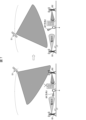
- FIG. 7 is a diagram showing an example of processing in the communication system 100 according to the present exemplary embodiment.
- communication terminal 4 cannot communicate with terrestrial base station B2 and non-terrestrial network base station S1 because they are blocked by a building. Therefore, communication terminal 4 is beamforming in BF direction 1 toward terrestrial base station B1, which is far away and has low reception power.
- the instruction unit 11 refers to at least one of the heat map and the trajectory information to instruct the communication terminal 4 on the beamforming direction to be used to start communication with a base station with which the communication terminal 4 is not communicating.
- the non-terrestrial network base station S1 has moved to a position where it can communicate with the communication terminal 4, so the instruction unit 11 instructs the communication terminal 4 to perform beamforming in the BF direction 2 to start communication with a base station with which the communication terminal 4 is not communicating, as shown on the right side of FIG. 7.
- the instruction unit 11 transmits instruction information to the communication terminal 4 indicating that it is instructing the communication terminal 4 to perform beamforming in the BF direction 2.
- the acquisition unit 42 of the communication terminal 4 acquires the instruction information from the communication terminal control device 3, it supplies the instruction information to the BF control unit 43.
- the BF control unit 43 performs beamforming in the BF direction 2 based on the instruction information.
- FIG. 8 is a diagram showing another example of the process in the communication system 100 according to the present exemplary embodiment.
- the communication terminal 4 is beamforming in the right direction of FIG. 8 based on the attitude of the communication terminal 4.
- the communication terminal 4 shown on the left side of FIG. 8 is in an attitude that does not allow beamforming in the left direction of FIG. 8. Therefore, the communication terminal 4 is beamforming in the BF direction 1 toward the non-terrestrial network base station S1.
- the instruction unit 11 refers to at least one of the heat map and the trajectory information to instruct the communication terminal 4 on the beamforming direction to be used to start communication with a base station with which the communication terminal 4 is not communicating.
- the non-terrestrial network base station S1 has moved to a position where the communication terminal 4 cannot perform beamforming, so the instruction unit 11 instructs the communication terminal 4 to perform beamforming in BF direction 2, which is a direction in which the communication terminal 4 can perform beamforming and in which terrestrial base station B2 is located, as shown on the right side of FIG. 8.
- the instruction unit 11 transmits instruction information to the communication terminal 4 indicating that it is instructing the communication terminal 4 to perform beamforming in BF direction 2.
- the acquisition unit 42 of the communication terminal 4 acquires the instruction information from the communication terminal control device 3, it supplies the instruction information to the BF control unit 43.
- the BF control unit 43 performs beamforming in the BF direction 2 based on the instruction information.
- the instruction unit 11 refers to the heat map, the trajectory information, and the attitude information to instruct the communication terminal 4 on the beamforming direction to be used to start communication with a base station with which the communication terminal 4 is not communicating. Therefore, the instruction unit 11 can cause the communication terminal 4 to perform beamforming in an appropriate direction when the communication terminal 4 starts handover or communication.
- the communication terminal 4 can instruct the communication terminal 4 on the beamforming direction toward the base station of the handover destination, so that the communication terminal 4 knows the handover destination in advance and can communicate without disconnection.
- the communication terminal 4 can be instructed on the beamforming direction to shorten the time of scanning to start communication. This can shorten the scan time.
- Some or all of the functions of the communication terminal control devices 1 and 3 and the communication terminal 4 may be realized by hardware such as an integrated circuit (IC chip), or may be realized by software.
- the communication terminal control devices 1, 3, and communication terminal 4 are realized, for example, by a computer that executes program instructions, which is software that realizes each function.
- a computer that executes program instructions, which is software that realizes each function.
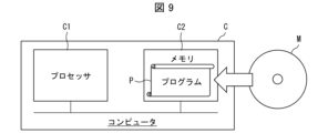
- An example of such a computer (hereinafter referred to as computer C) is shown in Figure 9.
- Computer C has at least one processor C1 and at least one memory C2.
- Memory C2 stores program P for operating computer C as communication terminal control devices 1, 3, and communication terminal 4.
- processor C1 reads and executes program P from memory C2, thereby realizing each function of communication terminal control devices 1, 3, and communication terminal 4.
- the processor C1 may be, for example, a CPU (Central Processing Unit), GPU (Graphic Processing Unit), DSP (Digital Signal Processor), MPU (Micro Processing Unit), FPU (Floating point number Processing Unit), PPU (Physics Processing Unit), microcontroller, or a combination of these.
- the memory C2 may be, for example, a flash memory, HDD (Hard Disk Drive), SSD (Solid State Drive), or a combination of these.
- Computer C may further include a RAM (Random Access Memory) for expanding program P during execution and for temporarily storing various data.
- Computer C may further include a communications interface for sending and receiving data to and from other devices.
- Computer C may further include an input/output interface for connecting input/output devices such as a keyboard, mouse, display, and printer.
- the program P can also be recorded on a non-transitory, tangible recording medium M that can be read by the computer C.
- a recording medium M can be, for example, a tape, a disk, a card, a semiconductor memory, or a programmable logic circuit.
- the computer C can obtain the program P via such a recording medium M.
- the program P can also be transmitted via a transmission medium.
- a transmission medium can be, for example, a communications network or broadcast waves.
- the computer C can also obtain the program P via such a transmission medium.
- a communication terminal control device having a beamforming function and including an instruction means for instructing a communication terminal capable of communicating with a terrestrial base station and a non-terrestrial network base station of a beamforming direction to be used to start communication with a base station with which the communication terminal is not communicating.
- the communication terminal control device comprising: an acquisition means for acquiring beamforming direction information indicating a beamforming direction of each of the plurality of communication terminals capable of communicating with the terrestrial base station and the non-terrestrial network base station, and location information indicating a location of each of the plurality of communication terminals; and a generation means for generating the heat map by referring to the beamforming direction information and the location information.
- Appendix 5 The communication terminal control device described in Appendix 4, wherein the acquisition means further acquires posture information indicating the posture of the multiple communication terminals from each of the multiple communication terminals, and the generation means further refers to the posture information and generates the heat map.
- the generation means divides an area included in the heat map into a plurality of meshes, and determines a beamforming direction in a mesh for which the acquisition means was unable to acquire BF direction information and position information by referring to a beamforming direction in a mesh adjacent to the mesh.
- the communication terminal control device according to claims 4 to 6.
- the non-terrestrial network base station is a low-earth orbit satellite, and the instruction means refers to orbit information indicating the orbit of the low-earth orbit satellite and instructs the beamforming direction of the communication terminal.
- the communication terminal control device according to any one of claims 1 to 7.
- Appendix 9 The communication terminal control device according to any one of appendices 1 to 8, wherein the instruction means instructs the communication terminal of a beamforming direction including an azimuth angle and an elevation angle.
- a communication terminal control method including a communication terminal control device instructing a communication terminal having a beamforming function and capable of communicating with a terrestrial base station and a non-terrestrial network base station of a beamforming direction to be used for starting communication with a base station with which the communication terminal is not communicating.
- Appendix 11 A program that causes a computer to function as a communications terminal control device, the program causing the computer to function as an instruction means for instructing a communications terminal that has a beamforming function and is capable of communicating with terrestrial base stations and non-terrestrial network base stations of a beamforming direction to be used to start communications with a base station with which the communications terminal is not communicating.
- a communication terminal control device comprising at least one processor, the processor having a beamforming function, and executing instruction processing to instruct a communication terminal capable of communicating with a terrestrial base station and a non-terrestrial network base station of a beamforming direction to be used to start communication with a base station with which the communication terminal is not communicating.
- the communication terminal control device may further include a memory, and the memory may store a program for causing the processor to execute the instruction process.
- the program may also be recorded on a computer-readable, non-transitory, tangible recording medium.
- a communication terminal control device comprising at least one processor, the at least one processor having a beamforming function, and executing an instruction process for instructing a communication terminal capable of communicating with a terrestrial base station and a non-terrestrial network base station of a beamforming direction to be used to start communication with a base station with which the communication terminal is not communicating.
- Appendix 4 The communication terminal control device described in Appendix 3, wherein the at least one processor executes an acquisition process to acquire BF direction information indicating the beamforming direction of each of the multiple communication terminals capable of communicating with the terrestrial base station and the non-terrestrial network base station and location information indicating the location of each of the multiple communication terminals, and a generation process to generate the heat map by referring to the BF direction information and the location information.
- Appendix 5 The communication terminal control device described in Appendix 4, wherein, in the acquisition process, the at least one processor further acquires posture information indicating the posture of the multiple communication terminals from each of the multiple communication terminals, and in the generation process, further refers to the posture information to generate the heat map.
- Appendix 6 The communication terminal control device described in Appendix 4 or 5, wherein, in the generation process, the at least one processor generates the heat map using a trained model that has been trained to input information about the communication terminal and output a direction in which radio wave strength is estimated to be high in the communication terminal.
- the at least one processor in the generation process, divides the area included in the heat map into a plurality of meshes, and determines the beamforming direction in a mesh for which the acquisition means was unable to acquire BF direction information and position information by referring to the beamforming direction in a mesh adjacent to the mesh.
- a communication terminal control device as described in any one of appendixes 4 to 6.
- the non-terrestrial network base station is a low-earth orbit satellite, and the at least one processor, in the instruction process, refers to orbit information indicating an orbit of the low-earth orbit satellite and instructs a beamforming direction of the communication terminal.
Landscapes
- Engineering & Computer Science (AREA)
- Computer Networks & Wireless Communication (AREA)
- Signal Processing (AREA)
- Physics & Mathematics (AREA)
- Astronomy & Astrophysics (AREA)
- General Physics & Mathematics (AREA)
- Mobile Radio Communication Systems (AREA)
Priority Applications (1)
| Application Number | Priority Date | Filing Date | Title |
|---|---|---|---|
| JP2024554294A JPWO2024095607A1 (https=) | 2022-10-31 | 2023-09-08 |
Applications Claiming Priority (2)
| Application Number | Priority Date | Filing Date | Title |
|---|---|---|---|
| JP2022174891 | 2022-10-31 | ||
| JP2022-174891 | 2022-10-31 |
Publications (1)
| Publication Number | Publication Date |
|---|---|
| WO2024095607A1 true WO2024095607A1 (ja) | 2024-05-10 |
Family
ID=90930169
Family Applications (1)
| Application Number | Title | Priority Date | Filing Date |
|---|---|---|---|
| PCT/JP2023/032781 Ceased WO2024095607A1 (ja) | 2022-10-31 | 2023-09-08 | 通信端末制御装置、通信端末制御方法、およびプログラム |
Country Status (2)
| Country | Link |
|---|---|
| JP (1) | JPWO2024095607A1 (https=) |
| WO (1) | WO2024095607A1 (https=) |
Citations (2)
| Publication number | Priority date | Publication date | Assignee | Title |
|---|---|---|---|---|
| WO2022028749A1 (en) * | 2020-08-06 | 2022-02-10 | Panasonic Intellectual Property Corporation Of America | Apparatuses and methods for determining if a user equipment is located in a registration area |
| WO2022037698A1 (en) * | 2020-08-21 | 2022-02-24 | Huawei Technologies Co., Ltd. | Systems and methods forangular direction indication in wireless communication |
-
2023
- 2023-09-08 JP JP2024554294A patent/JPWO2024095607A1/ja active Pending
- 2023-09-08 WO PCT/JP2023/032781 patent/WO2024095607A1/ja not_active Ceased
Patent Citations (2)
| Publication number | Priority date | Publication date | Assignee | Title |
|---|---|---|---|---|
| WO2022028749A1 (en) * | 2020-08-06 | 2022-02-10 | Panasonic Intellectual Property Corporation Of America | Apparatuses and methods for determining if a user equipment is located in a registration area |
| WO2022037698A1 (en) * | 2020-08-21 | 2022-02-24 | Huawei Technologies Co., Ltd. | Systems and methods forangular direction indication in wireless communication |
Also Published As
| Publication number | Publication date |
|---|---|
| JPWO2024095607A1 (https=) | 2024-05-10 |
Similar Documents
| Publication | Publication Date | Title |
|---|---|---|
| JP6633816B2 (ja) | 衛星プラットフォームにおけるソフトウェアアプリケーション展開のオーケストレーション | |
| US10299314B2 (en) | Autonomous mobile robot, movement control method, movement control program, and system | |
| US11878817B2 (en) | Satellite constellation forming system, satellite constellation forming method, satellite constellation, and ground device | |
| CN108886392B (zh) | 天线选择方法和电子设备 | |
| US12103711B2 (en) | Satellite constellation forming system, satellite constellation forming method, computer readable medium, and ground device | |
| CN120049171A (zh) | 电子设备对准卫星的方法和电子设备 | |
| CN114577203A (zh) | 个人导航装置、导航系统及相关方法 | |
| WO2024095607A1 (ja) | 通信端末制御装置、通信端末制御方法、およびプログラム | |
| US20210234606A1 (en) | System and method for providing beam planning for interference-aware satellite beam pattern design | |
| JP7586851B2 (ja) | 制御装置、プログラム、飛行体、システム、及び制御方法 | |
| CN116470284A (zh) | 一种波束指向高刷新率机载卫星通信相控阵天线 | |
| JP2018091786A (ja) | 妨害波源位置推定装置および妨害波源位置推定方法 | |
| JP2022093658A (ja) | 通信制御装置、通信制御方法、通信制御プログラム、通信制御システム、中継衛星、及び衛星システム | |
| CN115118330B (zh) | 多星协同在轨信息交互协议及时序设计方法、装置及介质 | |
| CN118740245A (zh) | 波束确认方法、装置、终端、可读存储介质和程序产品 | |
| JP7770687B2 (ja) | 通信処理回路および通信処理方法 | |
| US20220177165A1 (en) | Satellite constellation forming system, satellite constellation forming method, satellite constellation, deorbit method, debris collection method, and ground device | |
| JP7187503B2 (ja) | 通信装置、プログラム、移動体、システム、及び通信方法 | |
| JP7128386B1 (ja) | 宇宙航行体制御システム、宇宙航行体制御方法、及びサーバ装置。 | |
| JP5167902B2 (ja) | 情報伝送システム、該情報伝送システムに用いられる空中線制御方法及び空中線制御プログラム | |
| US20260113728A1 (en) | Communication control device | |
| JP7783667B1 (ja) | 信号発生源の位置を推定する推定装置、地球局、システム、方法、及びプログラム。 | |
| US12400385B2 (en) | Information processing apparatus, information processing method, program, and information processing system | |
| US20250167891A1 (en) | Communication planning device, satellite, and satellite system | |
| JP7607547B2 (ja) | 衛星情報伝送システム、静止衛星、および、地上設備 |
Legal Events
| Date | Code | Title | Description |
|---|---|---|---|
| 121 | Ep: the epo has been informed by wipo that ep was designated in this application |
Ref document number: 23885373 Country of ref document: EP Kind code of ref document: A1 |
|
| WWE | Wipo information: entry into national phase |
Ref document number: 2024554294 Country of ref document: JP |
|
| NENP | Non-entry into the national phase |
Ref country code: DE |
|
| 122 | Ep: pct application non-entry in european phase |
Ref document number: 23885373 Country of ref document: EP Kind code of ref document: A1 |