WO2024090279A1 - Rotor - Google Patents
Rotor Download PDFInfo
- Publication number
- WO2024090279A1 WO2024090279A1 PCT/JP2023/037447 JP2023037447W WO2024090279A1 WO 2024090279 A1 WO2024090279 A1 WO 2024090279A1 JP 2023037447 W JP2023037447 W JP 2023037447W WO 2024090279 A1 WO2024090279 A1 WO 2024090279A1
- Authority
- WO
- WIPO (PCT)
- Prior art keywords
- arc
- straight line
- shaped portion
- inter
- magnet insertion
- Prior art date
Links
- 238000003780 insertion Methods 0.000 claims abstract description 176
- 230000037431 insertion Effects 0.000 claims abstract description 176
- 230000001154 acute effect Effects 0.000 claims description 22
- 238000004519 manufacturing process Methods 0.000 description 19
- 230000000694 effects Effects 0.000 description 11
- 230000004907 flux Effects 0.000 description 6
- 239000013256 coordination polymer Substances 0.000 description 4
- 238000013459 approach Methods 0.000 description 2
- 230000000052 comparative effect Effects 0.000 description 2
- 230000007423 decrease Effects 0.000 description 2
- 230000004048 modification Effects 0.000 description 2
- 238000012986 modification Methods 0.000 description 2
- 238000005192 partition Methods 0.000 description 2
- 230000002093 peripheral effect Effects 0.000 description 2
- 229910000976 Electrical steel Inorganic materials 0.000 description 1
- 229910000831 Steel Inorganic materials 0.000 description 1
- 238000010586 diagram Methods 0.000 description 1
- 229910001172 neodymium magnet Inorganic materials 0.000 description 1
- 230000001151 other effect Effects 0.000 description 1
- 239000010959 steel Substances 0.000 description 1
Images


Classifications
-
- H—ELECTRICITY
- H02—GENERATION; CONVERSION OR DISTRIBUTION OF ELECTRIC POWER
- H02K—DYNAMO-ELECTRIC MACHINES
- H02K1/00—Details of the magnetic circuit
- H02K1/06—Details of the magnetic circuit characterised by the shape, form or construction
- H02K1/22—Rotating parts of the magnetic circuit
- H02K1/27—Rotor cores with permanent magnets
- H02K1/2706—Inner rotors
- H02K1/272—Inner rotors the magnetisation axis of the magnets being perpendicular to the rotor axis
- H02K1/274—Inner rotors the magnetisation axis of the magnets being perpendicular to the rotor axis the rotor consisting of two or more circumferentially positioned magnets
- H02K1/2753—Inner rotors the magnetisation axis of the magnets being perpendicular to the rotor axis the rotor consisting of two or more circumferentially positioned magnets the rotor consisting of magnets or groups of magnets arranged with alternating polarity
- H02K1/276—Magnets embedded in the magnetic core, e.g. interior permanent magnets [IPM]
Definitions
- the present invention relates to a rotor.
- rotors are known that have rotor cores that include bridge sections that are arranged adjacent to magnet insertion holes. Such rotors are disclosed, for example, in JP 2021-136785 A.
- JP 2021-136785 A discloses a rotor having a rotor core including a magnet insertion hole (magnet insertion hole) in which a permanent magnet is arranged, and a partition portion (bridge portion) arranged adjacent to the magnet insertion hole.
- the partition portion is arranged so that its width is as small as possible within a range that ensures the mechanical strength of the rotor core when viewed from the axial direction.
- the side surface of the magnet insertion hole is provided with a straight line (first straight line) that forms a bridge portion when viewed from the axial direction, a straight line (second straight line) that is arranged to extend in a direction along the long side of the permanent magnet, and an arc-shaped portion that is connected to the first straight line and the second straight line.
- JP 2021-136785 A in the conventional rotor as described in JP 2021-136785 A, it is considered that the arc-shaped portion is connected to the first straight line and the second straight line so that the first straight line and the second straight line are tangents to the circle corresponding to the arc-shaped portion so that the connection portion between the arc-shaped portion and the first straight line and the connection portion between the arc-shaped portion and the second straight line are not angular.
- the position of the connection portion where the arc-shaped portion and the first straight line are connected and the position of the connection portion where the arc-shaped portion and the second straight line are connected change. That is, the position of the arc-shaped portion of the magnet insertion hole changes.
- the angle between the first straight line and the second straight line is relatively small, the change in the position of the arc-shaped portion is relatively large. Accordingly, the shape (width or length) of the bridge portion formed by the first straight line connected to the arc-shaped portion changes.
- the bridge portion is provided so that its width is as small as possible when viewed from the axial direction within a range that ensures the mechanical strength of the rotor core. Therefore, if the shape of the bridge portion changes, the mechanical strength of the rotor core varies greatly. In addition, if the shape of the bridge portion changes, magnetic flux leakage may occur in the bridge portion. For this reason, a rotor that can suppress the increase in the variation in the mechanical strength of the rotor core caused by the change in the shape of the bridge portion and the occurrence of magnetic flux leakage in the bridge portion is desired.
- This invention was made to solve the above problems, and one of the objectives of this invention is to provide a rotor that can suppress the increase in variation in the mechanical strength of the rotor core caused by changes in the shape of the bridge section and the occurrence of magnetic flux leakage in the bridge section.
- a rotor in one aspect of the present invention includes a rotor core including a magnet insertion hole and a bridge portion provided adjacent to the magnet insertion hole, and a permanent magnet arranged in the magnet insertion hole, and the side surface of the magnet insertion hole is provided with a first straight line forming the bridge portion when viewed from the axial direction, a second straight line arranged to extend in a direction along the long side of the permanent magnet, a first arc-shaped portion connected to the first straight line and arranged between the first straight line and the second straight line, a second arc-shaped portion connected to the second straight line and arranged between the first straight line and the second straight line, and an inter-arc straight line portion connected to the first arc-shaped portion and connected to the second arc-shaped portion, or an inter-arc curved portion having a smaller curvature than the first arc-shaped portion and the second arc-shaped portion.
- the "direction along the long side of the permanent magnet” is a broad concept that
- the side surface of the magnet insertion hole is provided with a first straight line forming a bridge portion when viewed from the axial direction, a second straight line arranged to extend in a direction along the long side of the permanent magnet, a first arc-shaped portion connected to the first straight line and arranged between the first and second straight lines, a second arc-shaped portion connected to the second straight line and arranged between the first and second straight lines, and an inter-arc straight portion connected to the first arc-shaped portion and connected to the second arc-shaped portion, or an inter-arc curved portion having a smaller curvature than the first and second arc-shaped portions.
- first arc-shaped portion connected to the first straight line and connected to the inter-arc straight portion or the inter-arc curved portion
- second arc-shaped portion connected to the second straight line and connected to the inter-arc straight portion or the inter-arc curved portion.
- the tangent at the connection portion between the inter-arc straight line portion or the inter-arc curved line portion and the first arc-shaped portion and the tangent at the connection portion between the inter-arc curved line portion and the second arc-shaped portion extend in a direction intersecting the first straight line and the second straight line, so the angle between the first straight line and the tangent at the connection portion between the inter-arc straight line portion or the inter-arc curved line portion and the first arc-shaped portion and the angle between the second straight line and the tangent at the connection portion between the inter-arc straight line portion or the inter-arc curved line portion and the second arc-shaped portion are greater than the angle between the first straight line and the second straight line.
- the amount of change in the position of the arc-shaped portion in the direction in which the arc-shaped portion protrudes due to the change in the radius of the circle corresponding to the arc-shaped portion within the tolerance range increases as the absolute value of the angle between the straight line connected to one end of the arc-shaped portion and the straight line connected to the other end of the arc-shaped portion, or the angle between the straight line connected to one end of the arc-shaped portion and the tangent at the connection portion between the arc-shaped portion and the curve connected to the other end of the arc-shaped portion and having a smaller curvature than the arc-shaped portion, approaches 0 degrees (as the absolute value decreases).
- the amount of change in the shape of the bridge portion formed by the first straight line due to the change in the radius of the circle corresponding to the arc-shaped portion within the tolerance range can be reduced.
- the angle between the first line and the second line is preferably an acute angle.
- the angle between the first straight line and the tangent at the connection between the inter-arc straight line portion or the inter-arc curved line portion and the first arc-shaped portion, and the angle between the second straight line and the tangent at the connection between the inter-arc straight line portion or the inter-arc curved line portion and the second arc-shaped portion are preferably obtuse angles.
- the angle between the first straight line and the tangent to the connection between the inter-arc straight line portion or the inter-arc curved line portion and the first arc-shaped portion, and the angle between the second straight line and the tangent to the connection between the inter-arc straight line portion and the second arc-shaped portion are relatively large obtuse angles, so that the amount of change in the shape of the bridge portion formed by the first straight line that accompanies changes within the tolerance range (manufacturing error range) can be sufficiently reduced.
- the first straight line is preferably provided adjacent to a gap portion of the magnet insertion hole in which no permanent magnet is disposed.
- the bridge portion formed by the first straight line is positioned adjacent to the gap in the magnet insertion hole, and therefore the change in shape has a particularly large impact on the mechanical strength of the rotor core. Therefore, the amount of change in the shape of the bridge portion formed by the first straight line that occurs when the radius of the circle corresponding to the arc-shaped portion changes within the tolerance range (manufacturing error range) can be effectively reduced.
- the first straight line is preferably arranged to form a bridge portion located between adjacent magnet insertion holes arranged in a V-shape.
- the angle between the first straight line forming the bridge portion located between adjacent magnet insertion holes arranged in a V-shape and the second straight line is a relatively small acute angle, so that the amount of change in the shape of the bridge portion formed by the first straight line that accompanies changes within the tolerance range (manufacturing error range) can be effectively reduced.
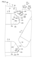
- FIG. 1 is a plan view showing a rotor according to a first embodiment of the present invention
- 3 is a plan view showing a first straight line, a second straight line, a first arc-shaped portion, a second arc-shaped portion, and an inter-arc straight line portion in a magnet insertion hole and a cutout of a rotor according to a first embodiment of the present invention.
- FIG. 13 is a diagram for explaining a change in the position of an arc-shaped portion as the radius of a circle corresponding to the arc-shaped portion changes within a tolerance range.
- FIG. 10 is a plan view showing a first straight line, a second straight line, a first arc-shaped portion, a second arc-shaped portion, and an inter-arc curve portion in a magnet insertion hole and a cutout of a rotor according to a second embodiment of the present invention.
- FIG. 13 is a plan view showing a first straight line, a second straight line, a first arc-shaped portion, a second arc-shaped portion, and an inter-arc straight line portion in a magnet insertion hole and a cutout of a rotor according to a comparative example.
- FIG. 13 is a plan view showing a first straight line, a second straight line, a first arc-shaped portion, a second arc-shaped portion, and an inter-arc straight line portion in a magnet insertion hole and a cutout of a rotor according to a comparative example.
- the axial, radial, and circumferential directions of the rotor 100 are referred to as the Z direction, R direction, and C direction, respectively.
- the inside and outside of the rotor 100 in the radial direction (R direction) are referred to as the R1 side and R2 side, respectively.
- One side and the other side of the rotor 100 in the circumferential direction (C direction) are referred to as the C1 side and C2 side, respectively.
- the rotor 100 is formed in an annular shape.
- the rotor 100 constitutes a part of an inner rotor type rotating electric machine (not shown) together with a stator (not shown) disposed on the R2 side of the rotor 100 so as to face the rotor 100.
- the rotating electric machine is, for example, a motor, a generator, or a motor/generator.
- the rotor 100 includes a rotor core 1.
- the rotor core 1 is constructed by stacking multiple electromagnetic steel plates (e.g., silicon steel plates) in the Z direction.
- Rotor core 1 includes magnet insertion holes 10. Magnet insertion holes 10 penetrate rotor core 1 in the Z direction. A plurality of magnet insertion holes 10 are provided in a portion of rotor core 1 on the R2 side.
- the magnet insertion holes 10 include a first magnet insertion hole 11, a second magnet insertion hole 12, a third magnet insertion hole 13, a fourth magnet insertion hole 14, a fifth magnet insertion hole 15, and a sixth magnet insertion hole 16.
- a set of the first magnet insertion hole 11, the second magnet insertion hole 12, the third magnet insertion hole 13, the fourth magnet insertion hole 14, the fifth magnet insertion hole 15, and the sixth magnet insertion hole 16 corresponds to one magnetic pole in the rotor core 1.
- the first magnet insertion hole 11 is positioned on the C1 side of the q axis so that the longitudinal direction of the first magnet insertion hole 11 extends along the R direction.
- the second magnet insertion hole 12 is positioned on the C2 side of the q axis so that the longitudinal direction of the second magnet insertion hole 12 extends along the R direction.
- the third magnet insertion hole 13 is arranged on the d-axis side of the first magnet insertion hole 11 so as to extend along the C direction.
- the C1 side end of the third magnet insertion hole 13 is arranged near the d-axis.
- the C2 side end of the third magnet insertion hole 13 is arranged near the R1 side end of the first magnet insertion hole 11.
- the first magnet insertion hole 11 and the third magnet insertion hole 13 are arranged in a V shape.
- the fourth magnet insertion hole 14 is arranged on the d-axis side of the second magnet insertion hole 12 so as to extend along the C direction.
- the C2 side end of the fourth magnet insertion hole 14 is arranged near the d-axis and opposite the C1 side end of the third magnet insertion hole 13.
- the C1 side end of the fourth magnet insertion hole 14 is arranged near the R1 side end of the second magnet insertion hole 12.
- the second magnet insertion hole 12 and the fourth magnet insertion hole 14 are arranged in a V shape.
- the fifth magnet insertion hole 15 is located on the R2 side of the third magnet insertion hole 13.
- the fifth magnet insertion hole 15 is located on the C2 side of the d axis, extending along the C direction.
- the C1 side end of the fifth magnet insertion hole 15 is located near the d axis.
- the sixth magnet insertion hole 16 is disposed on the R2 side of the fourth magnet insertion hole 14.
- the sixth magnet insertion hole 16 is disposed so as to extend along the C direction on the C1 side of the d axis.
- the C2 side end of the sixth magnet insertion hole 16 is disposed near the d axis and opposite the C1 side end of the fifth magnet insertion hole 15.
- the rotor core 1 includes a notch 20.
- the notch 20 penetrates the rotor core 1 in the Z direction.
- the notch 20 is formed in the outer circumferential portion 1a of the rotor core 1.
- the notch 20 is formed along the R direction.
- the notch 20 includes a first notch 21 and a second notch 22.
- the R1 end of the first cutout 21 is located near the C2 end of the fifth magnet insertion hole 15.
- the first cutout 21 and the fifth magnet insertion hole 15 are arranged in a V shape.
- the R1 end of the second cutout 22 is located near the C1 end of the sixth magnet insertion hole 16.
- the second cutout 22 and the sixth magnet insertion hole 16 are arranged in a V shape.
- Rotor core 1 includes bridge portions 30.
- Bridge portions 30 are provided adjacent to magnet insertion holes 10.
- Bridge portions 30 are formed so as to have a relatively small width when viewed from the Z direction, within a range in which the mechanical strength of rotor core 1 can be ensured.
- the bridge portion 30 includes a first bridge portion 31, a second bridge portion 32, a third bridge portion 33, a fourth bridge portion 34, a fifth bridge portion 35, a sixth bridge portion 36, a seventh bridge portion 37, and an eighth bridge portion 38.
- the first bridge portion 31 is provided between the R2 end of the first magnet insertion hole 11 and the outer peripheral surface of the rotor core 1.
- the second bridge portion 32 is provided between the R1 end of the first magnet insertion hole 11 and the C2 end of the third magnet insertion hole 13. In other words, the second bridge portion 32 is located between the adjacent first magnet insertion holes 11 and third magnet insertion holes 13 that are arranged in a V shape.
- the third bridge portion 33 is provided between the R2 end of the second magnet insertion hole 12 and the outer peripheral surface of the rotor core 1.
- the fourth bridge portion 34 is provided between the R1 end of the second magnet insertion hole 12 and the C1 end of the fourth magnet insertion hole 14. In other words, the fourth bridge portion 34 is located between the adjacent second magnet insertion holes 12 and fourth magnet insertion holes 14 that are arranged in a V shape.
- the fifth bridge portion 35 is provided between the C1 end of the third magnet insertion hole 13 and the C2 end of the fourth magnet insertion hole 14.
- the sixth bridge portion 36 is provided between the C1 end of the fifth magnet insertion hole 15 and the C2 end of the sixth magnet insertion hole 16.
- the seventh bridge portion 37 is provided between the C2 side end of the fifth magnet insertion hole 15 and the R1 side end of the first notch 21. That is, the seventh bridge portion 37 is located between the adjacent fifth magnet insertion holes 15 and the first notch 21, which are arranged in a V shape. In other words, the first notch 21 is formed so as to sandwich the seventh bridge portion 37 between itself and the fifth magnet insertion hole 15.
- the eighth bridge portion 38 is provided between the C1 side end of the sixth magnet insertion hole 16 and the R1 side end of the second notch 22. That is, the eighth bridge portion 38 is located between the adjacent sixth magnet insertion holes 16 and the second notch 22 that are arranged in a V shape. In other words, the second notch 22 is formed so as to sandwich the eighth bridge portion 38 between itself and the sixth magnet insertion hole 16.
- the rotor 100 includes a permanent magnet 2.
- the permanent magnet 2 has a rectangular shape when viewed from the Z direction.
- One permanent magnet 2 is disposed in each of the magnet insertion holes 10.
- the permanent magnet 2 is, for example, a neodymium magnet. Note that a gap 10a (see FIG. 2) is formed in a portion of the magnet insertion hole 10 where the permanent magnet 2 is not disposed.
- a first straight line L4a forming the fourth bridge portion 34
- a second straight line L4b arranged so as to extend in a direction along the long side of the permanent magnet 2
- a first arc-shaped portion L4c connected to the first straight line L4a and arranged between the first straight line L4a and the second straight line L4b
- a second arc-shaped portion L4d connected to the second straight line L4b and arranged between the first straight line L4a and the second straight line L4b
- an inter-arc straight portion L4e connected to the first arc-shaped portion L4c and connected to the second arc-shaped portion L4d.
- the first straight line L4a, the first arc-shaped portion L4c, the inter-arc straight portion L4e, the second arc-shaped portion L4d, and the second straight line L4b are connected in this order.
- the first arc-shaped portion L4c is connected to the first straight line L4a so that the first straight line L4a is a tangent to the first arc-shaped portion L4c so that the connection between the first straight line L4a and the first arc-shaped portion L4c is not angular. In other words, the first straight line L4a and the first arc-shaped portion L4c are smoothly connected. Furthermore, the first arc-shaped portion L4c is connected to the inter-arc straight line portion L4e so that the connection between the inter-arc straight line portion L4e and the first arc-shaped portion L4c is not angular. In other words, the inter-arc straight line portion L4e and the first arc-shaped portion L4c are smoothly connected.
- the second arc-shaped portion L4d is connected to the inter-arc straight line portion L4e so that the inter-arc straight line portion L4e is a tangent to the second arc-shaped portion L4d so that the connection between the inter-arc straight line portion L4e and the second arc-shaped portion L4d is not angular. That is, the inter-arc straight line portion L4e and the second arc-shaped portion L4d are smoothly connected.
- the second arc-shaped portion L4d is connected to the second straight line L4b so that the second straight line L4b is a tangent to the second arc-shaped portion L4d so that the connection portion between the second straight line L4b and the second arc-shaped portion L4d is not angular. That is, the second straight line L4b and the second arc-shaped portion L4d are smoothly connected.
- the angle A41 between the first straight line L4a and the second straight line L4b is an acute angle. That is, the first arc-shaped portion L4c, the second arc-shaped portion L4d, and the inter-arc straight line portion L4e are provided between the first straight line L4a and the second straight line L4b, which form the angle A41.
- the angle A42 between the first straight line L4a and the inter-arc straight line portion L4e is an obtuse angle. That is, the inter-arc straight line portion L4e is positioned so that the angle A42 with the first straight line L4a is an obtuse angle. Also, the angle A43 between the second straight line L4b and the inter-arc straight line portion L4e is an obtuse angle. That is, the inter-arc straight line portion L4e is positioned so that the angle A43 with the second straight line L4b is an obtuse angle.
- the first straight line L4a is arranged so as to be adjacent to the gap portion 10a of the fourth magnet insertion hole 14 where the permanent magnet 2 is not arranged.
- the first straight line L4a is also arranged so as to form a fourth bridge portion 34 located between the adjacent fourth magnet insertion holes 14 and second magnet insertion holes 12 arranged in a V-shape.
- a first straight line L6a forming the eighth bridge portion 38
- a second straight line L6b arranged so as to extend in a direction along the long side of the permanent magnet 2
- a first arc-shaped portion L6c connected to the first straight line L6a and arranged between the first straight line L6a and the second straight line L6b
- a second arc-shaped portion L6d connected to the second straight line L6b and arranged between the first straight line L6a and the second straight line L6b
- an inter-arc straight line portion L6e connected to the first arc-shaped portion L6c and connected to the second arc-shaped portion L6d.
- the first straight line L6a, the first arc-shaped portion L6c, the inter-arc straight line portion L6e, the second arc-shaped portion L6d, and the second straight line L6b are connected in this order.
- the first arc-shaped portion L6c is connected to the first straight line L6a so that the first straight line L6a is a tangent to the first arc-shaped portion L6c so that the connection portion between the first straight line L6a and the first arc-shaped portion L6c is not angular. In other words, the first straight line L6a and the first arc-shaped portion L6c are smoothly connected. Furthermore, the first arc-shaped portion L6c is connected to the inter-arc straight line portion L6e so that the connection portion between the inter-arc straight line portion L6e and the first arc-shaped portion L6c is not angular. In other words, the inter-arc straight line portion L6e and the first arc-shaped portion L6c are smoothly connected.
- the second arc-shaped portion L6d is connected to the inter-arc straight line portion L6e so that the inter-arc straight line portion L6e is a tangent to the second arc-shaped portion L6d so that the connection portion between the inter-arc straight line portion L6e and the second arc-shaped portion L6d is not angular. That is, the inter-arc straight line portion L6e and the second arc-shaped portion L6d are smoothly connected.
- the second arc-shaped portion L6d is connected to the second straight line L6b so that the second straight line L6b is a tangent to the second arc-shaped portion L6d so that the connection portion between the second straight line L6b and the second arc-shaped portion L6d is not angular. That is, the second straight line L6b and the second arc-shaped portion L6d are smoothly connected.
- the angle A61 between the first straight line L6a and the second straight line L6b is an acute angle.
- the first arc-shaped portion L6c, the second arc-shaped portion L6d, and the inter-arc straight line portion L6e are provided between the first straight line L6a and the second straight line L6b, which form the angle A61.
- the angle A62 between the first straight line L6a and the inter-arc straight line portion L6e is an obtuse angle. That is, the inter-arc straight line portion L6e is positioned so that the angle A62 with the first straight line L6a is an obtuse angle. Also, the angle A63 between the second straight line L6b and the inter-arc straight line portion L6e is an obtuse angle. That is, the inter-arc straight line portion L6e is positioned so that the angle A63 with the second straight line L6b is an obtuse angle.
- the first straight line L6a is arranged so as to be adjacent to the gap portion 10a of the sixth magnet insertion hole 16 in which the permanent magnet 2 is not arranged.
- the first straight line L6a is also arranged so as to form an eighth bridge portion 38 located between the adjacent sixth magnet insertion holes 16 and second cutouts 22 arranged in a V-shape.
- a first straight line L2a forming an eighth bridge portion 38
- a second straight line L2b arranged so as to face the first straight line L2a in the second cutout 22
- a first arc-shaped portion L2c connected to the first straight line L2a and arranged between the first straight line L2a and the second straight line L2b
- a second arc-shaped portion L2d connected to the second straight line L2b and arranged between the first straight line L2a and the second straight line L2b
- an inter-arc straight line portion L2e connected to the first arc-shaped portion L2c and connected to the second arc-shaped portion L2d.
- the first straight line L2a, the first arc-shaped portion L2c, the inter-arc straight line portion L2e, the second arc-shaped portion L2d, and the second straight line L2b are connected in this order.
- the first arc-shaped portion L2c is connected to the first straight line L2a so that the first straight line L2a is a tangent to the first arc-shaped portion L2c, so that the connection between the first straight line L2a and the first arc-shaped portion L2c is not angular. In other words, the first straight line L2a and the first arc-shaped portion L2c are smoothly connected. Furthermore, the first arc-shaped portion L2c is connected to the inter-arc straight line portion L2e so that the connection between the inter-arc straight line portion L2e and the first arc-shaped portion L2c is not angular. In other words, the inter-arc straight line portion L2e and the first arc-shaped portion L2c are smoothly connected.
- the second arc-shaped portion L2d is connected to the inter-arc straight line portion L2e so that the inter-arc straight line portion L2e is a tangent to the second arc-shaped portion L2d, so that the connection between the inter-arc straight line portion L2e and the second arc-shaped portion L2d is not angular. That is, the inter-arc straight line portion L2e and the second arc-shaped portion L2d are smoothly connected.
- the second arc-shaped portion L2d is connected to the second straight line L2b so that the second straight line L2b is a tangent to the second arc-shaped portion L2d so that the connection portion between the second straight line L2b and the second arc-shaped portion L2d is not angular. That is, the second straight line L2b and the second arc-shaped portion L2d are smoothly connected.
- the angle A21 between the first straight line L2a and the second straight line L2b is an acute angle. That is, the first arc-shaped portion L2c, the second arc-shaped portion L2d, and the inter-arc straight line portion L2e are provided between the first straight line L2a and the second straight line L2b, which form the angle A21.
- the angle A22 between the first straight line L2a and the inter-arc straight line portion L2e is an obtuse angle. That is, the inter-arc straight line portion L2e is positioned so that the angle A22 with the first straight line L2a is an obtuse angle. Also, the angle A23 between the second straight line L2b and the inter-arc straight line portion L2e is an obtuse angle. That is, the inter-arc straight line portion L2e is positioned so that the angle A23 with the second straight line L2b is an obtuse angle.
- the first straight line L2a is arranged to form an eighth bridge portion 38 located between adjacent second notches 22 and sixth magnet insertion holes 16 arranged in a V shape.
- the position of the connection portion CP S where the arc-shaped portion CA S and the straight line L1a are connected when the radius R of the circle is the minimum value R S of the tolerance range ⁇ R (range of manufacturing error)
- the position of the connection portion CP L where the arc-shaped portion CA L and the straight line L1a are connected when the radius R of the circle is the maximum value R L of the tolerance range ⁇ R, change by ⁇ X along the extension direction of the straight line L1a.
- connection portion CP S where the arc-shaped portion CA S and the straight line L1b are connected when the radius R of the circle is the minimum value R S of the tolerance range ⁇ R
- position of the connection portion CP L where the arc-shaped portion CA L and the straight line L1b are connected when the radius R of the circle is the maximum value R L of the tolerance range ⁇ R change by ⁇ X along the extension direction of the straight line L1b.
- an angle A42 formed by the first straight line L4a and the inter-arc straight portion L4e is an obtuse angle, so that the amount of change in the position of the first arc-shaped portion L4c that changes as the radius R of the circle corresponding to the first arc-shaped portion L4c changes within the tolerance range ⁇ R (the range of manufacturing error) is relatively small.
- an angle A43 formed by the second straight line L4b and the inter-arc straight portion L4e is an obtuse angle, so that the amount of change in the position of the second arc-shaped portion L4d that changes as the radius R of the circle corresponding to the second arc-shaped portion L4d changes within the tolerance range ⁇ R is relatively small.
- the first arc-shaped portion L4c when the radius R of the circle corresponding to the first arc-shaped portion L4c is the minimum value R_S of the tolerance range ⁇ R and the second arc-shaped portion L4d when the radius R of the circle corresponding to the second arc-shaped portion L4d is the minimum value R_S of the tolerance range ⁇ R are shown by solid lines, and the first arc-shaped portion L4c when the radius R of the circle corresponding to the first arc-shaped portion L4c is the maximum value R_L of the tolerance range ⁇ R and the second arc-shaped portion L4d when the radius R of the circle corresponding to the second arc-shaped portion L4d is the maximum value R_L of the tolerance range ⁇ R are shown by dotted lines.
- the content regarding the amount of change in the position of the above-mentioned arc-shaped portions in a configuration in which a first arc-shaped portion L4c, a second arc-shaped portion L4d, and an inter-arc straight portion L4e are provided between the first straight line L4a and the second straight line L4b is also the same in a configuration in which a first arc-shaped portion L6c, a second arc-shaped portion L6d, and an inter-arc straight portion L6e are provided between the first straight line L6a and the second straight line L6b, and in a configuration in which a first arc-shaped portion L2c, a second arc-shaped portion L2d, and an inter-arc straight portion L2e are provided between the first straight line L2a and the second straight line L2b.
- the angle A41 formed by the first straight line L4a and the second straight line L4b is an acute angle, so the amount of change in the position of the arc-shaped portion C4a that changes as the radius R of the circle corresponding to the arc-shaped portion C4a changes within the tolerance range ⁇ R (the range of manufacturing error) is relatively large. Note that in Fig.
- the arc-shaped portion C4a when the radius R of the circle corresponding to the arc-shaped portion C4a is the minimum value R S of the tolerance range ⁇ R is shown by a solid line
- the arc-shaped portion C4a when the radius R of the circle corresponding to the arc-shaped portion C4a is the maximum value R L of the tolerance range ⁇ R is shown by a dotted line.
- the content regarding the amount of change in the position of the above-mentioned arc-shaped portion in a configuration in which only one arc-shaped portion C4a is provided between the first straight line L4a and the second straight line L4b is the same as in a configuration in which only one arc-shaped portion is provided between the first straight line L6a and the second straight line L6b, and in a configuration in which only one arc-shaped portion is provided between the first straight line L2a and the second straight line L2b.
- the side surface of the fourth magnet insertion hole 14 is provided with a first straight line L4a that forms the fourth bridge portion 34 when viewed from the Z direction, a second straight line L4b that is arranged to extend in a direction along the long side of the permanent magnet 2, a first arc-shaped portion L4c that is connected to the first straight line L4a and arranged between the first straight line L4a and the second straight line L4b, a second arc-shaped portion L4d that is connected to the second straight line L4b and arranged between the first straight line L4a and the second straight line L4b, and an inter-arc straight portion L4e that is connected to the first arc-shaped portion L4c and connected to the second arc-shaped portion L4d.
- the angle A42 formed by the first straight line L4a and the inter-arc straight portion L4e and the angle A43 formed by the second straight line L4b and the inter-arc straight portion L4e are greater than the angle A41 formed by the first straight line L4a and the second straight line L4b.
- the amount of change ⁇ C in the position of the arc-shaped portion CA in the direction in which the arc-shaped portion CA protrudes which is caused by the radius R of the circle corresponding to the arc-shaped portion CA changing within the tolerance range ⁇ R (the range of manufacturing error), becomes larger as the absolute value of the angle ⁇ formed by the line connected to one end of the arc-shaped portion CA and the line connected to the other end of the arc-shaped portion CA becomes closer to 0 degrees (smaller).
- the amount of change in the shape of the fourth bridge portion 34 formed by the first straight line L4a due to the change in the radius R of the circle corresponding to the first arc-shaped portion L4c and the radius R of the circle corresponding to the second arc-shaped portion L4d within the tolerance range ⁇ R can be reduced.
- the sixth magnet insertion hole 16 and the second cutout 22 also provide the same effect as the fourth magnet insertion hole 14 described above.
- the angle A41 between the first straight line L4a and the second straight line L4b is an acute angle.
- the amount of change in the shape of the fourth bridge portion 34 formed by the first straight line L4a due to the change in each of the radius R of the circle corresponding to the first arc-shaped portion L4c and the radius R of the circle corresponding to the second arc-shaped portion L4d within the tolerance range ⁇ R becomes relatively large.
- the amount of change in the shape of the fourth bridge portion 34 formed by the first straight line L4a due to the change in each of the radius R of the circle corresponding to the first arc-shaped portion L4c and the radius R of the circle corresponding to the second arc-shaped portion L4d within the tolerance range ⁇ R (manufacturing error range) can be effectively reduced.
- the sixth magnet insertion hole 16 and the second notch 22 also provide the same effect as the fourth magnet insertion hole 14 described above.
- the angle A42 between the first straight line L4a and the inter-arc straight line portion L4e is an obtuse angle.
- the angle A43 between the second straight line L4b and the inter-arc straight line portion L4e is an obtuse angle.
- the angle A42 between the first straight line L4a and the inter-arc straight line portion L4e and the angle A43 between the second straight line L4b and the inter-arc straight line portion L4e are relatively large obtuse angles, so that the amount of change in the shape of the fourth bridge portion 34 formed by the first straight line L4a caused by the change in each of the radius R of the circle corresponding to the first arc-shaped portion L4c and the radius R of the circle corresponding to the second arc-shaped portion L4d within the tolerance range ⁇ R (manufacturing error range) can be sufficiently reduced.
- the sixth magnet insertion hole 16 and the second cutout 22 also provide the same effect as the fourth magnet insertion hole 14.
- the first straight line L4a is provided adjacent to the gap 10a of the fourth magnet insertion hole 14 where the permanent magnet 2 is not arranged.
- the fourth bridge portion 34 formed by the first straight line L4a has a particularly large effect on the mechanical strength of the rotor core 1 due to the change in shape, caused by being provided adjacent to the gap 10a of the fourth magnet insertion hole 14.
- the amount of change in the shape of the fourth bridge portion 34 formed by the first straight line L4a caused by the change in each of the radius R of the circle corresponding to the first arc-shaped portion L4c and the radius R of the circle corresponding to the second arc-shaped portion L4d within the tolerance range ⁇ R (manufacturing error range) can be effectively reduced. Note that the same effect as the fourth magnet insertion hole 14 described above can be obtained in the sixth magnet insertion hole 16 as well.
- the first straight line L4a is provided to form the fourth bridge portion 34 located between the adjacent fourth magnet insertion holes 14 and second magnet insertion holes 12 arranged in a V-shape.
- the angle A41 formed by the first straight line L4a, which forms the fourth bridge portion 34 located between the adjacent fourth magnet insertion holes 14 and second magnet insertion holes 12 arranged in a V-shape, and the second straight line L4b is a relatively small acute angle, so that the amount of change in the shape of the fourth bridge portion 34 formed by the first straight line L4a that accompanies changes in each of the radius R of the circle corresponding to the first arc-shaped portion L4c and the radius R of the circle corresponding to the second arc-shaped portion L4d within the tolerance range ⁇ R (manufacturing error range) can be effectively reduced.
- the rotor 200 includes a rotor core 201 .
- the rotor core 201 includes magnet insertion holes 210.
- the magnet insertion holes 210 include a second magnet insertion hole 212, a fourth magnet insertion hole 214, and a sixth magnet insertion hole 216.
- the rotor core 201 includes a notch 220.
- the notch 220 includes a second notch 222.
- the rotor core 201 includes a bridge portion 230.
- the bridge portion 230 includes a fourth bridge portion 234 and an eighth bridge portion 238.
- the side surface of the fourth magnet insertion hole 214 is provided with a first straight line L4a forming the fourth bridge portion 234, a second straight line L4b arranged to extend in a direction along the long side of the permanent magnet 2, a first arc-shaped portion L24c connected to the first straight line L4a and arranged between the first straight line L4a and the second straight line L4b, a second arc-shaped portion L24d connected to the second straight line L4b and arranged between the first straight line L4a and the second straight line L4b, and an arc-to-arc curved portion L24e connected to the first arc-shaped portion L24c and to the second arc-shaped portion L24d and having a smaller curvature than the first arc-shaped portion L24c and the second arc-shaped portion L24d, as viewed from the Z direction.
- the first straight line L4a, the first arc-shaped portion L24c, the arc-to-arc curved portion L24e, the second arc-shaped portion L24d, and the second straight line L4b are connected in this order.
- the first arc-shaped portion L24c is connected to the first straight line L4a such that the first straight line L4a is tangent to the first arc-shaped portion L24c so that the connection portion between the first straight line L4a and the first arc-shaped portion L24c is not angular.
- the first straight line L4a and the first arc-shaped portion L24c are smoothly connected.
- the first arc-shaped portion L24c is connected to the inter-arc curved portion L24e such that the inter-arc curved portion L24e is tangent to the first arc-shaped portion L24c so that the connection portion between the inter-arc curved portion L24e and the first arc-shaped portion L24c is not angular.
- the inter-arc curved portion L24e and the first arc-shaped portion L24c are smoothly connected.
- the second arc-shaped portion L24d is connected to the inter-arc curve portion L24e so that the inter-arc curve portion L24e is tangent to the second arc-shaped portion L24d so that the connection portion between the inter-arc curve portion L24e and the second arc-shaped portion L24d is not angular. That is, the inter-arc curve portion L24e and the second arc-shaped portion L24d are smoothly connected.
- the second arc-shaped portion L24d is connected to the second straight line L4b so that the second straight line L4b is tangent to the second arc-shaped portion L24d so that the connection portion between the second straight line L4b and the second arc-shaped portion L24d is not angular. That is, the second straight line L4b and the second arc-shaped portion L24d are smoothly connected.
- the first arc-shaped portion L24c, the inter-arc curved portion L24e, and the second arc-shaped portion L24d are formed so that 2 ⁇ R ⁇ r1+r2+(L/cos(2- ⁇ /2)) holds, where r1 is the radius of the first arc-shaped portion L24c, r2 is the radius of the second arc-shaped portion L24d, L is the distance between the center of the circle corresponding to the first arc-shaped portion L24c and the center of the circle corresponding to the second arc-shaped portion L24d, R is the radius of the inter-arc curved portion L24e, and ⁇ is the angle between the first straight line L4a and the second straight line L4b.
- the angle A242 between the first straight line L4a and the tangent at the connection between the inter-arc curved portion L24e and the first arc-shaped portion L24c is an obtuse angle.
- the angle A243 between the second straight line L4b and the tangent at the connection between the inter-arc curved portion L24e and the second arc-shaped portion L24d is an obtuse angle.
- the first straight line L6a, the first arc-shaped portion L26c, the inter-arc curved portion L26e, the second arc-shaped portion L26d, and the second straight line L6b are connected in this order.
- the first straight line L6a and the first arc-shaped portion L26c are smoothly connected so that the connection portion between them is not angular. Furthermore, the inter-arc curved portion L26e and the first arc-shaped portion L26c are smoothly connected so that the connection portion between them is not angular. Furthermore, the inter-arc curved portion L26e and the second arc-shaped portion L26d are smoothly connected so that the connection portion between them is not angular. Furthermore, the second straight line L4b and the second arc-shaped portion L26d are smoothly connected so that the connection portion between them is not angular.
- the first arc-shaped portion L26c, the inter-arc curved portion L26e and the second arc-shaped portion L26d are formed so that 2 ⁇ R ⁇ r1+r2+(L/cos(2- ⁇ /2)) holds, where r1 is the radius of the first arc-shaped portion L26c, r2 is the radius of the second arc-shaped portion L26d, L is the distance between the center of the circle corresponding to the first arc-shaped portion L26c and the center of the circle corresponding to the second arc-shaped portion L26d, R is the radius of the inter-arc curved portion L26e and ⁇ is the angle between the first straight line L4a and the second straight line L4b.
- the angle A262 between the first straight line L6a and the tangent at the connection between the inter-arc curved portion L26e and the first arc-shaped portion L26c is an obtuse angle.
- the angle A263 between the second straight line L6b and the tangent at the connection between the inter-arc curved portion L26e and the second arc-shaped portion L26d is an obtuse angle.
- the first straight line L2a, the first arc-shaped portion L22c, the inter-arc curved portion L22e, the second arc-shaped portion L22d, and the second straight line L2b are connected in this order.
- the first arc-shaped portion L22c is connected to the first straight line L2a such that the first straight line L2a is tangent to the first arc-shaped portion L22c so that the connection portion between the first straight line L2a and the first arc-shaped portion L22c is not angular.
- the first straight line L2a and the first arc-shaped portion L22c are smoothly connected.
- the first arc-shaped portion L22c is connected to the inter-arc curved portion L22e such that the inter-arc curved portion L22e is tangent to the first arc-shaped portion L22c so that the connection portion between the inter-arc curved portion L22e and the first arc-shaped portion L22c is not angular.
- the inter-arc curved portion L22e and the first arc-shaped portion L22c are smoothly connected.
- the second arc-shaped portion L22d is connected to the inter-arc curve portion L22e so that the inter-arc curve portion L22e is tangent to the second arc-shaped portion L22d so that the connection portion between the inter-arc curve portion L22e and the second arc-shaped portion L22d is not angular. That is, the inter-arc curve portion L22e and the second arc-shaped portion L22d are smoothly connected.
- the second arc-shaped portion L22d is connected to the second straight line L2b so that the second straight line L2b is tangent to the second arc-shaped portion L22d so that the connection portion between the second straight line L2b and the second arc-shaped portion L22d is not angular. That is, the second straight line L2b and the second arc-shaped portion L22d are smoothly connected.
- the first arc-shaped portion L22c, the inter-arc curved portion L22e, and the second arc-shaped portion L22d are formed so that 2 ⁇ R ⁇ r1+r2+(L/cos(2 ⁇ /2)) holds, where r1 is the radius of the first arc-shaped portion L22c, r2 is the radius of the second arc-shaped portion L22d, L is the distance between the center of the circle corresponding to the first arc-shaped portion L22c and the center of the circle corresponding to the second arc-shaped portion L26d, R is the radius of the inter-arc curved portion L22e, and ⁇ is the angle between the first straight line L4a and the second straight line L4b.
- the angle A222 between the first straight line L2a and the tangent at the connection between the inter-arc curved portion L22e and the first arc-shaped portion L22c is an obtuse angle.
- the angle A223 between the second straight line L2b and the tangent at the connection between the inter-arc curved portion L22e and the second arc-shaped portion L22d is an obtuse angle.
- the rest of the configuration of the rotor 200 of the second embodiment is the same as that of the rotor 100 of the first embodiment.
- the side of the fourth magnet insertion hole 214 is provided with a first straight line L4a that forms the fourth bridge portion 234 when viewed from the Z direction, a second straight line L4b that is arranged to extend in a direction along the long side of the permanent magnet 2, a first arc-shaped portion L24c that is connected to the first straight line L4a and is arranged between the first straight line L4a and the second straight line L4b, a second arc-shaped portion L24d that is connected to the second straight line L4b and is arranged between the first straight line L4a and the second straight line L4b, and an inter-arc curve portion L24e that is connected to the first arc-shaped portion L24c and to the second arc-shaped portion L24d and has a smaller curvature than the first arc-shaped portion L24c and the second arc-shaped portion L24d.
- first arc-shaped portion L24c connected to the first straight line L4a and connected to the arc-to-arc curve portion L24e
- second arc-shaped portion L24d connected to the second straight line L4b and connected to the arc-to-arc curve portion L24e.
- the tangent at the connection portion between the arc-arc curved portion L24e and the first arc-shaped portion L24c and the tangent at the connection portion between the arc-arc curved portion L24e and the second arc-shaped portion L24d extend in a direction intersecting the first straight line L4a and the second straight line L4b, so the angle A242 formed by the first straight line L4a and the tangent at the connection portion between the arc-arc curved portion L24e and the first arc-shaped portion L24c, and the angle A243 formed by the second straight line L4b and the tangent at the connection portion between the arc-arc curved portion L24e and the second arc-shaped portion L24d are greater than the angle A41 formed by the first straight line L4a and the second straight line L4b.
- the change amount ⁇ C of the position of the arc-shaped portion CA in the protruding direction of the arc-shaped portion CA accompanying the change in the radius R of the circle corresponding to the arc-shaped portion CA within the tolerance range ⁇ R increases as the absolute value of the angle ⁇ between the straight line connected to one end of the arc-shaped portion CA and the tangent of the connection portion between the arc-shaped portion and the curve connected to the other end of the arc-shaped portion and having a smaller curvature than the arc-shaped portion approaches 0 degrees (as the angle ⁇ decreases).
- the change amount of the shape of the fourth bridge portion 234 formed by the first straight line L4a accompanying the change in the radius R of the circle corresponding to the first arc-shaped portion L24c and the radius R of the circle corresponding to the second arc-shaped portion L24d within the tolerance range ⁇ R can be reduced.
- the sixth magnet insertion hole 216 and the second cutout 222 also provide the same effect as the fourth magnet insertion hole 214 described above.
- the angle A242 between the first straight line L4a and the tangent at the connection between the inter-arc curved portion L24e and the first arc-shaped portion L24c is an obtuse angle.
- the angle A243 between the second straight line L4b and the tangent at the connection between the inter-arc curved portion L24e and the second arc-shaped portion L24d is an obtuse angle.
- the angle A242 between the first straight line L4a and the tangent at the connection between the inter-arc curved portion L24e and the first arc-shaped portion L24c, and the angle A243 between the second straight line L4b and the tangent at the connection between the inter-arc curved portion L24e and the second arc-shaped portion L24d are relatively large obtuse angles, so that the amount of change in the shape of the fourth bridge portion 234 formed by the first straight line L4a caused by the change in each of the radius R of the circle corresponding to the first arc-shaped portion L24c and the radius R of the circle corresponding to the second arc-shaped portion L24d within the tolerance range ⁇ R (manufacturing error range) can be sufficiently reduced.
- the sixth magnet insertion hole 216 and the second cutout 222 also have the same effect as the fourth magnet insertion hole 214.
- the first straight line L2a is provided to form the eighth bridge portion 38 (238) located between the adjacent second cutouts 22 (222) and the sixth magnet insertion hole 16 (216) arranged in a V-shape, but the present invention is not limited to this.
- the first straight line L2a does not have to be provided to form the eighth bridge portion 38 (238) located between the adjacent second cutouts 22 (222) and the sixth magnet insertion hole 16 (216) arranged in a V-shape
- the first straight line may be provided to form the seventh bridge portion 37 located between the adjacent first cutouts 21 and the fifth magnet insertion hole 15 arranged in a V-shape.
- first straight line L4a is arranged to form a fourth bridge portion 34 (234) located between adjacent fourth magnet insertion holes 14 (214) and second magnet insertion holes 12 (212) arranged in a V-shape
- first straight line L6a is arranged to form an eighth bridge portion 38 (238) located between adjacent sixth magnet insertion holes 16 (216) and second notches 22 (222) arranged in a V-shape
- present invention is not limited to this.
- the first straight line L4a does not have to be arranged to form the fourth bridge portion 34 (234) located between the adjacent fourth magnet insertion holes 14 (214) and second magnet insertion holes 12 (212) arranged in a V-shape
- the first straight line L6a does not have to be arranged to form the eighth bridge portion 38 (238) located between the adjacent sixth magnet insertion holes 16 (216) and second notch 22 (222) arranged in a V-shape
- the first straight line may be arranged to form a bridge portion other than the fourth bridge portion 34 (234) and the sixth bridge portion 36 (236) located between the adjacent magnet insertion holes arranged in a V-shape.
- first straight line L4a is arranged adjacent to the gap portion 10a in the fourth magnet insertion hole 14 (214) in which a permanent magnet 2 is not placed
- first straight line L6a is arranged adjacent to the gap portion 10a in the sixth magnet insertion hole 16 (216) in which a permanent magnet 2 is not placed
- present invention is not limited to this.
- the first straight line L4a does not have to be arranged adjacent to the gap 10a in the fourth magnet insertion hole 14 (214) in which the permanent magnet 2 is not arranged
- the first straight line L6a does not have to be arranged adjacent to the gap 10a in the sixth magnet insertion hole 16 (216) in which the permanent magnet 2 is not arranged
- the first straight line may be arranged adjacent to the gap 10a in the magnet insertion holes 10 (210) other than the fourth magnet insertion hole 14 (214) and the sixth magnet insertion hole 16 (216) in which the permanent magnet 2 is not arranged.
- the angle A42 (A242) between the first straight line L4a and the inter-arc straight line portion L4e (the tangent at the connection portion between the inter-arc curved portion L24e and the first arc-shaped portion L24c), and the angle A43 (A243) between the second straight line L4b and the inter-arc straight line portion L4e (the tangent at the connection portion between the inter-arc curved portion L24e and the second arc-shaped portion L24d) are obtuse angles
- the angle A62 (A262) between the first straight line L6a and the inter-arc straight line portion L6e (the tangent at the connection portion between the inter-arc curved portion L26e and the first arc-shaped portion L26c) An example has been shown in which the angle A63 (A263) between the second straight line L6b and the inter-arc straight portion L6e (a tangent to the connection portion between the inter-arc curved portion L26e and the second arc-shaped portion L26c).
- the angle A42 (A242) between the first straight line L4a and the inter-arc straight line portion L4e (a tangent to a connection portion between the inter-arc curved line portion L24e and the first arc-shaped portion L24c) and the angle A43 (A243) between the second straight line L4b and the inter-arc straight line portion L4e (a tangent to a connection portion between the inter-arc curved line portion L24e and the second arc-shaped portion L24d) may be an acute angle
- the angle A43 (A243) between the first straight line L6a and the inter-arc straight line portion L6e (the inter-arc curved line portion L24d) may be an acute angle.
- the angle A62 (A262) between the second straight line L6b and the inter-arc straight line portion L6e (a tangent at a connection portion between the inter-arc curved line portion L26e and the first arc-shaped portion L26c) and the angle A63 (A263) between the second straight line L6b and the inter-arc straight line portion L2e (a tangent at a connection portion between the inter-arc curved line portion L26e and the second arc-shaped portion L26d) may be an acute angle
- the angle A63 (A263) between the first straight line L2a and the inter-arc straight line portion L2e (a tangent at a connection portion between the inter-arc curved line portion L22e and the first arc-shaped portion L22c) may be an acute angle.
- the angle A23 (A223) between the second straight line L2b and the inter-arc straight line portion L2e (a tangent to the connection portion between the inter-arc curved line portion L22e and the second arc-shaped portion L22d) may be an acute angle, or in magnet insertion holes 10 (210) other than the fourth magnet insertion hole 14 (214) and the sixth magnet insertion hole 16 (216), the angle A23 (A223) between the first straight line and the inter-arc straight line portion (a tangent to the connection portion between the inter-arc curved line portion and the first arc-shaped portion) may be an acute angle.
- the angle and the angle between the second straight line and the inter-arc straight line portion may be obtuse angles, and in the first cutout 21, the angle between the first straight line and the inter-arc straight line portion (tangent to the connection between the inter-arc curved portion and the first arc-shaped portion) and the angle between the second straight line and the inter-arc straight line portion (tangent to the connection between the inter-arc curved portion and the second arc-shaped portion) may be obtuse angles.
- the angle A41 between the first line L4a and the second line L4b is an acute angle
- the angle A61 between the first line L6a and the second line L6b is an acute angle
- the angle A21 between the first line L2a and the second line L2b is an acute angle.
- the present invention is not limited to this.
- the angle A41 between the first line L4a and the second line L4b may be an obtuse angle
- the angle A61 between the first line L6a and the second line L6b may be an obtuse angle
- the angle A21 between the first line L2a and the second line L2b may be an obtuse angle
- the angle between the first line and the second line in the magnet insertion holes 10 (210) other than the fourth magnet insertion hole 14 (214) and the sixth magnet insertion hole 16 (216) and in the first cutout 21 may be an acute angle.
- Reference Signs List 1 201 rotor core 1a outer periphery (of rotor core) 2 permanent magnet 10, 210 magnet insertion hole 10a gap (adjacent to the permanent magnet on the bridge portion side of the magnet insertion hole) 30, 230 bridge portion 100, 200 rotor A41, A61 angle (between first line and second line) A42, A43 angle (between first line and inter-arc straight line portion) A62, A63 angle (between second line and inter-arc straight line portion) A242, A243 angle (between first line and inter-arc curved line portion) A262, A263 angle (between second line and inter-arc curved line portion) L4a, L6a first line L4b, L6b second line L4c, L6c, L24c, L26c first arc-shaped portion L4d, L6d, L24d, L26d: second arc-shaped portion L4e, L6e: straight line portion between arcs L24e, L26e: curved portion between arcs
Landscapes
- Engineering & Computer Science (AREA)
- Power Engineering (AREA)
- Permanent Field Magnets Of Synchronous Machinery (AREA)
Abstract
Ce rotor a, sur la surface latérale d'un trou d'insertion d'aimant lorsqu'il est vu dans une direction axiale, une première ligne droite formant une partie de pont, une seconde ligne droite disposée de façon à s'étendre dans une direction le long du côté long d'un aimant permanent, une première partie d'arc circulaire reliée à la première ligne droite et disposée entre les première et seconde lignes droites, une seconde partie d'arc circulaire reliée à la seconde ligne droite et disposée entre les première et seconde lignes droites, et une partie droite inter-arc circulaire reliée à la première partie d'arc circulaire et à la seconde partie d'arc circulaire.
Applications Claiming Priority (2)
| Application Number | Priority Date | Filing Date | Title |
|---|---|---|---|
| JP2022-172716 | 2022-10-27 | ||
| JP2022172716 | 2022-10-27 |
Publications (1)
| Publication Number | Publication Date |
|---|---|
| WO2024090279A1 true WO2024090279A1 (fr) | 2024-05-02 |
Family
ID=90830685
Family Applications (1)
| Application Number | Title | Priority Date | Filing Date |
|---|---|---|---|
| PCT/JP2023/037447 WO2024090279A1 (fr) | 2022-10-27 | 2023-10-16 | Rotor |
Country Status (1)
| Country | Link |
|---|---|
| WO (1) | WO2024090279A1 (fr) |
Citations (4)
| Publication number | Priority date | Publication date | Assignee | Title |
|---|---|---|---|---|
| JP2013081302A (ja) * | 2011-10-04 | 2013-05-02 | Hitachi Automotive Systems Ltd | 永久磁石式回転電機および永久磁石式回転電機を備えた車両 |
| JP2014060836A (ja) * | 2012-09-14 | 2014-04-03 | Denso Corp | 回転電機のロータ |
| WO2015087773A1 (fr) * | 2013-12-09 | 2015-06-18 | 三菱電機株式会社 | Moteur électrique à aimant permanent intégré |
| JP2022544250A (ja) * | 2019-09-30 | 2022-10-17 | ファーウェイ デジタル パワー テクノロジーズ カンパニー リミテッド | ロータコア層状体、ロータコア、ロータ、永久磁石同期モータ及び関連製品 |
-
2023
- 2023-10-16 WO PCT/JP2023/037447 patent/WO2024090279A1/fr unknown
Patent Citations (4)
| Publication number | Priority date | Publication date | Assignee | Title |
|---|---|---|---|---|
| JP2013081302A (ja) * | 2011-10-04 | 2013-05-02 | Hitachi Automotive Systems Ltd | 永久磁石式回転電機および永久磁石式回転電機を備えた車両 |
| JP2014060836A (ja) * | 2012-09-14 | 2014-04-03 | Denso Corp | 回転電機のロータ |
| WO2015087773A1 (fr) * | 2013-12-09 | 2015-06-18 | 三菱電機株式会社 | Moteur électrique à aimant permanent intégré |
| JP2022544250A (ja) * | 2019-09-30 | 2022-10-17 | ファーウェイ デジタル パワー テクノロジーズ カンパニー リミテッド | ロータコア層状体、ロータコア、ロータ、永久磁石同期モータ及び関連製品 |
Similar Documents
| Publication | Publication Date | Title |
|---|---|---|
| US9705366B2 (en) | Embedded permanent magnet rotary electric machine | |
| JP5104554B2 (ja) | ロータ | |
| US10439459B2 (en) | Rotor | |
| JP5443778B2 (ja) | 永久磁石式回転電機の回転子及びその回転電機 | |
| EP1164684A2 (fr) | Rotor pour moteur synchrone | |
| US8519593B2 (en) | Brushless motor with low cogging torque | |
| JP5695747B2 (ja) | 回転電機用ローター | |
| US9912204B2 (en) | Permanent magnet type rotating electric machine | |
| US11190070B2 (en) | Rotor for rotating electrical machine | |
| US20150270752A1 (en) | Permanent-magnet-type rotating electric mechanism | |
| JP2018153047A (ja) | 回転電機のロータ | |
| JP6947284B2 (ja) | 回転電機のロータおよび回転電機のロータコア支持構造 | |
| JP2007295708A (ja) | 永久磁石埋め込み型モータ | |
| TWI575843B (zh) | 徑向繞線馬達定子 | |
| US20130207501A1 (en) | Rotary electric machine | |
| WO2024090279A1 (fr) | Rotor | |
| US11611251B2 (en) | Motor having asymmetric rotor core | |
| WO2020100675A1 (fr) | Rotor et machine électrique rotative équipée de celui-ci | |
| EP4220899A1 (fr) | Noyau de rotor | |
| JP5879848B2 (ja) | 埋込磁石形回転電機のロータ | |
| WO2023045264A1 (fr) | Structure de rotor, structure de moteur électrique et dispositif électronique | |
| EP3480928B1 (fr) | Machine électrique rotative à réluctance synchrone | |
| US20210159745A1 (en) | Rotor lamination, rotor laminated core, rotor, electric machine, and vehicle | |
| US20220045564A1 (en) | Rotor | |
| WO2023190446A1 (fr) | Rotor de machine électrique rotative |
Legal Events
| Date | Code | Title | Description |
|---|---|---|---|
| 121 | Ep: the epo has been informed by wipo that ep was designated in this application |
Ref document number: 23882485 Country of ref document: EP Kind code of ref document: A1 |