WO2024090206A1 - Negative electrode for secondary battery, and secondary battery - Google Patents
Negative electrode for secondary battery, and secondary battery Download PDFInfo
- Publication number
- WO2024090206A1 WO2024090206A1 PCT/JP2023/036845 JP2023036845W WO2024090206A1 WO 2024090206 A1 WO2024090206 A1 WO 2024090206A1 JP 2023036845 W JP2023036845 W JP 2023036845W WO 2024090206 A1 WO2024090206 A1 WO 2024090206A1
- Authority
- WO
- WIPO (PCT)
- Prior art keywords
- negative electrode
- dicarboxylic acid
- half region
- content
- acid component
- Prior art date
Links
- OFOBLEOULBTSOW-UHFFFAOYSA-N Malonic acid Chemical compound OC(=O)CC(O)=O OFOBLEOULBTSOW-UHFFFAOYSA-N 0.000 claims abstract description 93
- 239000000203 mixture Substances 0.000 claims abstract description 82
- 150000008064 anhydrides Chemical class 0.000 claims abstract description 15
- 239000007773 negative electrode material Substances 0.000 claims description 48
- VZCYOOQTPOCHFL-OWOJBTEDSA-N Fumaric acid Chemical compound OC(=O)\C=C\C(O)=O VZCYOOQTPOCHFL-OWOJBTEDSA-N 0.000 claims description 46
- OKTJSMMVPCPJKN-UHFFFAOYSA-N Carbon Chemical compound [C] OKTJSMMVPCPJKN-UHFFFAOYSA-N 0.000 claims description 28
- VZCYOOQTPOCHFL-UHFFFAOYSA-N trans-butenedioic acid Natural products OC(=O)C=CC(O)=O VZCYOOQTPOCHFL-UHFFFAOYSA-N 0.000 claims description 25
- 239000001530 fumaric acid Substances 0.000 claims description 23
- 239000000463 material Substances 0.000 claims description 20
- 239000011246 composite particle Substances 0.000 claims description 17
- VYPSYNLAJGMNEJ-UHFFFAOYSA-N Silicium dioxide Chemical compound O=[Si]=O VYPSYNLAJGMNEJ-UHFFFAOYSA-N 0.000 claims description 15
- 229910052799 carbon Inorganic materials 0.000 claims description 15
- BPQQTUXANYXVAA-UHFFFAOYSA-N Orthosilicate Chemical compound [O-][Si]([O-])([O-])[O-] BPQQTUXANYXVAA-UHFFFAOYSA-N 0.000 claims description 14
- XUIMIQQOPSSXEZ-UHFFFAOYSA-N Silicon Chemical compound [Si] XUIMIQQOPSSXEZ-UHFFFAOYSA-N 0.000 claims description 14
- 229910052710 silicon Inorganic materials 0.000 claims description 14
- 239000010703 silicon Substances 0.000 claims description 14
- 229910052814 silicon oxide Inorganic materials 0.000 claims description 13
- 150000001991 dicarboxylic acids Chemical class 0.000 claims description 10
- LVHBHZANLOWSRM-UHFFFAOYSA-N itaconic acid Chemical compound OC(=O)CC(=C)C(O)=O LVHBHZANLOWSRM-UHFFFAOYSA-N 0.000 claims description 10
- PAZHGORSDKKUPI-UHFFFAOYSA-N lithium metasilicate Chemical compound [Li+].[Li+].[O-][Si]([O-])=O PAZHGORSDKKUPI-UHFFFAOYSA-N 0.000 claims description 9
- 229910052912 lithium silicate Inorganic materials 0.000 claims description 9
- 239000007770 graphite material Substances 0.000 claims description 4
- HNEGQIOMVPPMNR-NSCUHMNNSA-N mesaconic acid Chemical compound OC(=O)C(/C)=C/C(O)=O HNEGQIOMVPPMNR-NSCUHMNNSA-N 0.000 claims description 4
- HNEGQIOMVPPMNR-UHFFFAOYSA-N methylfumaric acid Natural products OC(=O)C(C)=CC(O)=O HNEGQIOMVPPMNR-UHFFFAOYSA-N 0.000 claims description 4
- LIVNPJMFVYWSIS-UHFFFAOYSA-N silicon monoxide Chemical compound [Si-]#[O+] LIVNPJMFVYWSIS-UHFFFAOYSA-N 0.000 claims description 2
- 239000013543 active substance Substances 0.000 abstract 1
- 239000010410 layer Substances 0.000 description 94
- 239000002131 composite material Substances 0.000 description 45
- 239000002002 slurry Substances 0.000 description 37
- 239000002245 particle Substances 0.000 description 27
- 239000011248 coating agent Substances 0.000 description 19
- 238000000576 coating method Methods 0.000 description 19
- 230000000052 comparative effect Effects 0.000 description 15
- 229910052751 metal Inorganic materials 0.000 description 14
- 239000002184 metal Substances 0.000 description 14
- 239000006229 carbon black Substances 0.000 description 10
- 238000007789 sealing Methods 0.000 description 10
- 239000011230 binding agent Substances 0.000 description 9
- 229910003481 amorphous carbon Inorganic materials 0.000 description 8
- 239000004020 conductor Substances 0.000 description 8
- 238000001035 drying Methods 0.000 description 8
- 239000010408 film Substances 0.000 description 8
- 150000003839 salts Chemical class 0.000 description 8
- 239000003125 aqueous solvent Substances 0.000 description 7
- 229920005989 resin Polymers 0.000 description 7
- 239000011347 resin Substances 0.000 description 7
- 239000007784 solid electrolyte Substances 0.000 description 7
- XLYOFNOQVPJJNP-UHFFFAOYSA-N water Substances O XLYOFNOQVPJJNP-UHFFFAOYSA-N 0.000 description 7
- 229920002134 Carboxymethyl cellulose Polymers 0.000 description 6
- 150000002739 metals Chemical class 0.000 description 6
- -1 polytetrafluoroethylene Polymers 0.000 description 6
- 229920003048 styrene butadiene rubber Polymers 0.000 description 6
- RYGMFSIKBFXOCR-UHFFFAOYSA-N Copper Chemical compound [Cu] RYGMFSIKBFXOCR-UHFFFAOYSA-N 0.000 description 5
- WHXSMMKQMYFTQS-UHFFFAOYSA-N Lithium Chemical compound [Li] WHXSMMKQMYFTQS-UHFFFAOYSA-N 0.000 description 5
- 239000006230 acetylene black Substances 0.000 description 5
- 239000003575 carbonaceous material Substances 0.000 description 5
- 239000010949 copper Substances 0.000 description 5
- 229910052744 lithium Inorganic materials 0.000 description 5
- 238000005259 measurement Methods 0.000 description 5
- 238000005096 rolling process Methods 0.000 description 5
- HBBGRARXTFLTSG-UHFFFAOYSA-N Lithium ion Chemical compound [Li+] HBBGRARXTFLTSG-UHFFFAOYSA-N 0.000 description 4
- 239000002033 PVDF binder Substances 0.000 description 4
- 239000004372 Polyvinyl alcohol Substances 0.000 description 4
- 229910045601 alloy Inorganic materials 0.000 description 4
- 239000000956 alloy Substances 0.000 description 4
- 229910052796 boron Inorganic materials 0.000 description 4
- 239000002041 carbon nanotube Substances 0.000 description 4
- 229910021393 carbon nanotube Inorganic materials 0.000 description 4
- 239000001768 carboxy methyl cellulose Substances 0.000 description 4
- 235000010948 carboxy methyl cellulose Nutrition 0.000 description 4
- 239000008112 carboxymethyl-cellulose Substances 0.000 description 4
- 239000003792 electrolyte Substances 0.000 description 4
- 229910002804 graphite Inorganic materials 0.000 description 4
- 239000010439 graphite Substances 0.000 description 4
- 229910001416 lithium ion Inorganic materials 0.000 description 4
- 238000000034 method Methods 0.000 description 4
- PXHVJJICTQNCMI-UHFFFAOYSA-N nickel Substances [Ni] PXHVJJICTQNCMI-UHFFFAOYSA-N 0.000 description 4
- 239000011255 nonaqueous electrolyte Substances 0.000 description 4
- 229920002239 polyacrylonitrile Polymers 0.000 description 4
- 229920005672 polyolefin resin Polymers 0.000 description 4
- 229920001343 polytetrafluoroethylene Polymers 0.000 description 4
- 239000004810 polytetrafluoroethylene Substances 0.000 description 4
- 229920002451 polyvinyl alcohol Polymers 0.000 description 4
- 229920002981 polyvinylidene fluoride Polymers 0.000 description 4
- 239000007774 positive electrode material Substances 0.000 description 4
- 229920000178 Acrylic resin Polymers 0.000 description 3
- 239000004925 Acrylic resin Substances 0.000 description 3
- 229910052783 alkali metal Inorganic materials 0.000 description 3
- 229910052784 alkaline earth metal Inorganic materials 0.000 description 3
- 229910052782 aluminium Inorganic materials 0.000 description 3
- 229910052787 antimony Inorganic materials 0.000 description 3
- 125000003178 carboxy group Chemical group [H]OC(*)=O 0.000 description 3
- 150000001875 compounds Chemical class 0.000 description 3
- 239000011889 copper foil Substances 0.000 description 3
- 239000011888 foil Substances 0.000 description 3
- 239000003273 ketjen black Substances 0.000 description 3
- 229910052745 lead Inorganic materials 0.000 description 3
- 229910003002 lithium salt Inorganic materials 0.000 description 3
- 159000000002 lithium salts Chemical class 0.000 description 3
- 239000011777 magnesium Substances 0.000 description 3
- 229910052748 manganese Inorganic materials 0.000 description 3
- 238000004519 manufacturing process Methods 0.000 description 3
- 239000011159 matrix material Substances 0.000 description 3
- 229920000642 polymer Polymers 0.000 description 3
- 230000009467 reduction Effects 0.000 description 3
- 239000011734 sodium Substances 0.000 description 3
- 239000007787 solid Substances 0.000 description 3
- 239000000243 solution Substances 0.000 description 3
- 239000002904 solvent Substances 0.000 description 3
- 229910052725 zinc Inorganic materials 0.000 description 3
- JAHNSTQSQJOJLO-UHFFFAOYSA-N 2-(3-fluorophenyl)-1h-imidazole Chemical compound FC1=CC=CC(C=2NC=CN=2)=C1 JAHNSTQSQJOJLO-UHFFFAOYSA-N 0.000 description 2
- OIFBSDVPJOWBCH-UHFFFAOYSA-N Diethyl carbonate Chemical compound CCOC(=O)OCC OIFBSDVPJOWBCH-UHFFFAOYSA-N 0.000 description 2
- KMTRUDSVKNLOMY-UHFFFAOYSA-N Ethylene carbonate Chemical compound O=C1OCCO1 KMTRUDSVKNLOMY-UHFFFAOYSA-N 0.000 description 2
- YCKRFDGAMUMZLT-UHFFFAOYSA-N Fluorine atom Chemical compound [F] YCKRFDGAMUMZLT-UHFFFAOYSA-N 0.000 description 2
- 239000004698 Polyethylene Substances 0.000 description 2
- 239000004743 Polypropylene Substances 0.000 description 2
- 229920002125 Sokalan® Polymers 0.000 description 2
- 230000002378 acidificating effect Effects 0.000 description 2
- 125000001931 aliphatic group Chemical group 0.000 description 2
- 239000012736 aqueous medium Substances 0.000 description 2
- QHIWVLPBUQWDMQ-UHFFFAOYSA-N butyl prop-2-enoate;methyl 2-methylprop-2-enoate;prop-2-enoic acid Chemical compound OC(=O)C=C.COC(=O)C(C)=C.CCCCOC(=O)C=C QHIWVLPBUQWDMQ-UHFFFAOYSA-N 0.000 description 2
- 239000011575 calcium Substances 0.000 description 2
- 239000011247 coating layer Substances 0.000 description 2
- 229910052802 copper Inorganic materials 0.000 description 2
- 230000000694 effects Effects 0.000 description 2
- 239000008151 electrolyte solution Substances 0.000 description 2
- JBTWLSYIZRCDFO-UHFFFAOYSA-N ethyl methyl carbonate Chemical compound CCOC(=O)OC JBTWLSYIZRCDFO-UHFFFAOYSA-N 0.000 description 2
- 229910052731 fluorine Inorganic materials 0.000 description 2
- 239000011737 fluorine Substances 0.000 description 2
- 125000000524 functional group Chemical group 0.000 description 2
- 229910021385 hard carbon Inorganic materials 0.000 description 2
- 229910052739 hydrogen Inorganic materials 0.000 description 2
- 239000001257 hydrogen Substances 0.000 description 2
- 229910003480 inorganic solid Inorganic materials 0.000 description 2
- 229910052742 iron Inorganic materials 0.000 description 2
- 230000002427 irreversible effect Effects 0.000 description 2
- 229910052747 lanthanoid Inorganic materials 0.000 description 2
- 150000002602 lanthanoids Chemical class 0.000 description 2
- 239000011244 liquid electrolyte Substances 0.000 description 2
- 229910021437 lithium-transition metal oxide Inorganic materials 0.000 description 2
- 229910052749 magnesium Inorganic materials 0.000 description 2
- VZCYOOQTPOCHFL-UPHRSURJSA-N maleic acid Chemical compound OC(=O)\C=C/C(O)=O VZCYOOQTPOCHFL-UPHRSURJSA-N 0.000 description 2
- 239000011976 maleic acid Substances 0.000 description 2
- 239000002609 medium Substances 0.000 description 2
- 239000012046 mixed solvent Substances 0.000 description 2
- 238000002156 mixing Methods 0.000 description 2
- 150000007524 organic acids Chemical class 0.000 description 2
- 229910052760 oxygen Inorganic materials 0.000 description 2
- 229920000573 polyethylene Polymers 0.000 description 2
- 229920001721 polyimide Polymers 0.000 description 2
- 239000009719 polyimide resin Substances 0.000 description 2
- 239000005518 polymer electrolyte Substances 0.000 description 2
- 239000002861 polymer material Substances 0.000 description 2
- 229920001155 polypropylene Polymers 0.000 description 2
- 238000002360 preparation method Methods 0.000 description 2
- 239000011856 silicon-based particle Substances 0.000 description 2
- 229910052708 sodium Inorganic materials 0.000 description 2
- 229910021384 soft carbon Inorganic materials 0.000 description 2
- 238000000859 sublimation Methods 0.000 description 2
- 230000008022 sublimation Effects 0.000 description 2
- 238000003466 welding Methods 0.000 description 2
- 229910052727 yttrium Inorganic materials 0.000 description 2
- 239000011701 zinc Substances 0.000 description 2
- XVOUMQNXTGKGMA-OWOJBTEDSA-N (E)-glutaconic acid Chemical compound OC(=O)C\C=C\C(O)=O XVOUMQNXTGKGMA-OWOJBTEDSA-N 0.000 description 1
- SMZOUWXMTYCWNB-UHFFFAOYSA-N 2-(2-methoxy-5-methylphenyl)ethanamine Chemical compound COC1=CC=C(C)C=C1CCN SMZOUWXMTYCWNB-UHFFFAOYSA-N 0.000 description 1
- NIXOWILDQLNWCW-UHFFFAOYSA-N 2-Propenoic acid Natural products OC(=O)C=C NIXOWILDQLNWCW-UHFFFAOYSA-N 0.000 description 1
- GYXGAEAOIFNGAE-UHFFFAOYSA-N 2-propan-2-ylidenebutanedioic acid Chemical compound CC(C)=C(C(O)=O)CC(O)=O GYXGAEAOIFNGAE-UHFFFAOYSA-N 0.000 description 1
- SBLRHMKNNHXPHG-UHFFFAOYSA-N 4-fluoro-1,3-dioxolan-2-one Chemical compound FC1COC(=O)O1 SBLRHMKNNHXPHG-UHFFFAOYSA-N 0.000 description 1
- ZDZVKPXKLLLOOA-UHFFFAOYSA-N Allylmalonic acid Chemical compound OC(=O)C(C(O)=O)CC=C ZDZVKPXKLLLOOA-UHFFFAOYSA-N 0.000 description 1
- OYPRJOBELJOOCE-UHFFFAOYSA-N Calcium Chemical compound [Ca] OYPRJOBELJOOCE-UHFFFAOYSA-N 0.000 description 1
- 229920003043 Cellulose fiber Polymers 0.000 description 1
- LFQSCWFLJHTTHZ-UHFFFAOYSA-N Ethanol Chemical compound CCO LFQSCWFLJHTTHZ-UHFFFAOYSA-N 0.000 description 1
- 208000033962 Fontaine progeroid syndrome Diseases 0.000 description 1
- UFHFLCQGNIYNRP-UHFFFAOYSA-N Hydrogen Chemical compound [H][H] UFHFLCQGNIYNRP-UHFFFAOYSA-N 0.000 description 1
- DGAQECJNVWCQMB-PUAWFVPOSA-M Ilexoside XXIX Chemical compound C[C@@H]1CC[C@@]2(CC[C@@]3(C(=CC[C@H]4[C@]3(CC[C@@H]5[C@@]4(CC[C@@H](C5(C)C)OS(=O)(=O)[O-])C)C)[C@@H]2[C@]1(C)O)C)C(=O)O[C@H]6[C@@H]([C@H]([C@@H]([C@H](O6)CO)O)O)O.[Na+] DGAQECJNVWCQMB-PUAWFVPOSA-M 0.000 description 1
- 229910001357 Li2MPO4F Inorganic materials 0.000 description 1
- 229910001556 Li2Si2O5 Inorganic materials 0.000 description 1
- 229910007843 Li2zSiO Inorganic materials 0.000 description 1
- 229910001305 LiMPO4 Inorganic materials 0.000 description 1
- 229910001290 LiPF6 Inorganic materials 0.000 description 1
- 229910001091 LixCoO2 Inorganic materials 0.000 description 1
- 229910016780 LixCoyM1-yOz Inorganic materials 0.000 description 1
- 229910016784 LixCoyM1−yOz Inorganic materials 0.000 description 1
- 229910016819 LixCoyNi1-yO2 Inorganic materials 0.000 description 1
- 229910016818 LixCoyNi1−yO2 Inorganic materials 0.000 description 1
- 229910015220 LixMn2-yMyO4 Inorganic materials 0.000 description 1
- 229910015329 LixMn2O4 Inorganic materials 0.000 description 1
- 229910015283 LixMn2−yMyO4 Inorganic materials 0.000 description 1
- 229910003007 LixMnO2 Inorganic materials 0.000 description 1
- 229910014240 LixNi1-yMyOz Inorganic materials 0.000 description 1
- 229910014052 LixNi1−yMyOz Inorganic materials 0.000 description 1
- 229910014149 LixNiO2 Inorganic materials 0.000 description 1
- 229910052765 Lutetium Inorganic materials 0.000 description 1
- FYYHWMGAXLPEAU-UHFFFAOYSA-N Magnesium Chemical compound [Mg] FYYHWMGAXLPEAU-UHFFFAOYSA-N 0.000 description 1
- CERQOIWHTDAKMF-UHFFFAOYSA-N Methacrylic acid Chemical compound CC(=C)C(O)=O CERQOIWHTDAKMF-UHFFFAOYSA-N 0.000 description 1
- 239000004721 Polyphenylene oxide Substances 0.000 description 1
- ZLMJMSJWJFRBEC-UHFFFAOYSA-N Potassium Chemical compound [K] ZLMJMSJWJFRBEC-UHFFFAOYSA-N 0.000 description 1
- 229910000676 Si alloy Inorganic materials 0.000 description 1
- UCKMPCXJQFINFW-UHFFFAOYSA-N Sulphide Chemical compound [S-2] UCKMPCXJQFINFW-UHFFFAOYSA-N 0.000 description 1
- 238000002441 X-ray diffraction Methods 0.000 description 1
- 239000002253 acid Substances 0.000 description 1
- 239000000853 adhesive Substances 0.000 description 1
- 230000001070 adhesive effect Effects 0.000 description 1
- 125000003158 alcohol group Chemical group 0.000 description 1
- 150000001340 alkali metals Chemical class 0.000 description 1
- XAGFODPZIPBFFR-UHFFFAOYSA-N aluminium Chemical compound [Al] XAGFODPZIPBFFR-UHFFFAOYSA-N 0.000 description 1
- 150000001408 amides Chemical class 0.000 description 1
- 229910021486 amorphous silicon dioxide Inorganic materials 0.000 description 1
- 239000004760 aramid Substances 0.000 description 1
- 229920003235 aromatic polyamide Polymers 0.000 description 1
- 229910021383 artificial graphite Inorganic materials 0.000 description 1
- 125000003118 aryl group Chemical group 0.000 description 1
- QVGXLLKOCUKJST-UHFFFAOYSA-N atomic oxygen Chemical compound [O] QVGXLLKOCUKJST-UHFFFAOYSA-N 0.000 description 1
- 229910052788 barium Inorganic materials 0.000 description 1
- DSAJWYNOEDNPEQ-UHFFFAOYSA-N barium atom Chemical compound [Ba] DSAJWYNOEDNPEQ-UHFFFAOYSA-N 0.000 description 1
- 239000002585 base Substances 0.000 description 1
- 239000011324 bead Substances 0.000 description 1
- 230000005540 biological transmission Effects 0.000 description 1
- 230000015572 biosynthetic process Effects 0.000 description 1
- 229910052797 bismuth Inorganic materials 0.000 description 1
- 230000003139 buffering effect Effects 0.000 description 1
- 229910052791 calcium Inorganic materials 0.000 description 1
- 239000011203 carbon fibre reinforced carbon Substances 0.000 description 1
- 150000001732 carboxylic acid derivatives Chemical class 0.000 description 1
- 229920002678 cellulose Polymers 0.000 description 1
- 239000001913 cellulose Substances 0.000 description 1
- 239000000919 ceramic Substances 0.000 description 1
- 229910052804 chromium Inorganic materials 0.000 description 1
- HNEGQIOMVPPMNR-IHWYPQMZSA-N citraconic acid Chemical compound OC(=O)C(/C)=C\C(O)=O HNEGQIOMVPPMNR-IHWYPQMZSA-N 0.000 description 1
- 229940018557 citraconic acid Drugs 0.000 description 1
- 238000007906 compression Methods 0.000 description 1
- 229920001577 copolymer Polymers 0.000 description 1
- IFDVQVHZEKPUSC-UHFFFAOYSA-N cyclohex-3-ene-1,2-dicarboxylic acid Chemical compound OC(=O)C1CCC=CC1C(O)=O IFDVQVHZEKPUSC-UHFFFAOYSA-N 0.000 description 1
- IEJIGPNLZYLLBP-UHFFFAOYSA-N dimethyl carbonate Chemical compound COC(=O)OC IEJIGPNLZYLLBP-UHFFFAOYSA-N 0.000 description 1
- 238000007599 discharging Methods 0.000 description 1
- 239000007772 electrode material Substances 0.000 description 1
- 150000002148 esters Chemical class 0.000 description 1
- 150000002170 ethers Chemical class 0.000 description 1
- 238000001125 extrusion Methods 0.000 description 1
- 239000000835 fiber Substances 0.000 description 1
- 239000007789 gas Substances 0.000 description 1
- 238000002290 gas chromatography-mass spectrometry Methods 0.000 description 1
- 239000000499 gel Substances 0.000 description 1
- 229910052736 halogen Inorganic materials 0.000 description 1
- 125000005843 halogen group Chemical group 0.000 description 1
- 150000002367 halogens Chemical class 0.000 description 1
- 230000020169 heat generation Effects 0.000 description 1
- 125000004435 hydrogen atom Chemical group [H]* 0.000 description 1
- 125000002887 hydroxy group Chemical group [H]O* 0.000 description 1
- 238000009413 insulation Methods 0.000 description 1
- 230000010220 ion permeability Effects 0.000 description 1
- 150000002500 ions Chemical class 0.000 description 1
- 238000010030 laminating Methods 0.000 description 1
- 229910052746 lanthanum Inorganic materials 0.000 description 1
- FZLIPJUXYLNCLC-UHFFFAOYSA-N lanthanum atom Chemical compound [La] FZLIPJUXYLNCLC-UHFFFAOYSA-N 0.000 description 1
- RSNHXDVSISOZOB-UHFFFAOYSA-N lithium nickel Chemical compound [Li].[Ni] RSNHXDVSISOZOB-UHFFFAOYSA-N 0.000 description 1
- OHSVLFRHMCKCQY-UHFFFAOYSA-N lutetium atom Chemical compound [Lu] OHSVLFRHMCKCQY-UHFFFAOYSA-N 0.000 description 1
- 230000007246 mechanism Effects 0.000 description 1
- 239000011859 microparticle Substances 0.000 description 1
- 239000000178 monomer Substances 0.000 description 1
- 229910021382 natural graphite Inorganic materials 0.000 description 1
- 229910052759 nickel Inorganic materials 0.000 description 1
- 229910052758 niobium Inorganic materials 0.000 description 1
- 150000002825 nitriles Chemical class 0.000 description 1
- 239000004745 nonwoven fabric Substances 0.000 description 1
- 239000001301 oxygen Substances 0.000 description 1
- 230000000737 periodic effect Effects 0.000 description 1
- 230000002093 peripheral effect Effects 0.000 description 1
- 229910052698 phosphorus Inorganic materials 0.000 description 1
- 229920000570 polyether Polymers 0.000 description 1
- 229910052700 potassium Inorganic materials 0.000 description 1
- 239000011591 potassium Substances 0.000 description 1
- 230000036316 preload Effects 0.000 description 1
- 239000002994 raw material Substances 0.000 description 1
- 230000002441 reversible effect Effects 0.000 description 1
- 229910052706 scandium Inorganic materials 0.000 description 1
- 239000000377 silicon dioxide Substances 0.000 description 1
- 235000012239 silicon dioxide Nutrition 0.000 description 1
- 229910052712 strontium Inorganic materials 0.000 description 1
- CIOAGBVUUVVLOB-UHFFFAOYSA-N strontium atom Chemical compound [Sr] CIOAGBVUUVVLOB-UHFFFAOYSA-N 0.000 description 1
- 230000001629 suppression Effects 0.000 description 1
- 239000002344 surface layer Substances 0.000 description 1
- 229910052715 tantalum Inorganic materials 0.000 description 1
- UFDHBDMSHIXOKF-UHFFFAOYSA-N tetrahydrophthalic acid Natural products OC(=O)C1=C(C(O)=O)CCCC1 UFDHBDMSHIXOKF-UHFFFAOYSA-N 0.000 description 1
- 229920005992 thermoplastic resin Polymers 0.000 description 1
- 239000010409 thin film Substances 0.000 description 1
- 229910052718 tin Inorganic materials 0.000 description 1
- 229910052719 titanium Inorganic materials 0.000 description 1
- 229910052723 transition metal Inorganic materials 0.000 description 1
- 229910052721 tungsten Inorganic materials 0.000 description 1
- 229910052720 vanadium Inorganic materials 0.000 description 1
- 239000002759 woven fabric Substances 0.000 description 1
- 229910052726 zirconium Inorganic materials 0.000 description 1
Images


Classifications
-
- H—ELECTRICITY
- H01—ELECTRIC ELEMENTS
- H01M—PROCESSES OR MEANS, e.g. BATTERIES, FOR THE DIRECT CONVERSION OF CHEMICAL ENERGY INTO ELECTRICAL ENERGY
- H01M4/00—Electrodes
- H01M4/02—Electrodes composed of, or comprising, active material
- H01M4/13—Electrodes for accumulators with non-aqueous electrolyte, e.g. for lithium-accumulators; Processes of manufacture thereof
- H01M4/133—Electrodes based on carbonaceous material, e.g. graphite-intercalation compounds or CFx
-
- H—ELECTRICITY
- H01—ELECTRIC ELEMENTS
- H01M—PROCESSES OR MEANS, e.g. BATTERIES, FOR THE DIRECT CONVERSION OF CHEMICAL ENERGY INTO ELECTRICAL ENERGY
- H01M4/00—Electrodes
- H01M4/02—Electrodes composed of, or comprising, active material
- H01M4/13—Electrodes for accumulators with non-aqueous electrolyte, e.g. for lithium-accumulators; Processes of manufacture thereof
- H01M4/134—Electrodes based on metals, Si or alloys
-
- H—ELECTRICITY
- H01—ELECTRIC ELEMENTS
- H01M—PROCESSES OR MEANS, e.g. BATTERIES, FOR THE DIRECT CONVERSION OF CHEMICAL ENERGY INTO ELECTRICAL ENERGY
- H01M4/00—Electrodes
- H01M4/02—Electrodes composed of, or comprising, active material
- H01M4/13—Electrodes for accumulators with non-aqueous electrolyte, e.g. for lithium-accumulators; Processes of manufacture thereof
- H01M4/136—Electrodes based on inorganic compounds other than oxides or hydroxides, e.g. sulfides, selenides, tellurides, halogenides or LiCoFy
-
- H—ELECTRICITY
- H01—ELECTRIC ELEMENTS
- H01M—PROCESSES OR MEANS, e.g. BATTERIES, FOR THE DIRECT CONVERSION OF CHEMICAL ENERGY INTO ELECTRICAL ENERGY
- H01M4/00—Electrodes
- H01M4/02—Electrodes composed of, or comprising, active material
- H01M4/36—Selection of substances as active materials, active masses, active liquids
- H01M4/38—Selection of substances as active materials, active masses, active liquids of elements or alloys
-
- H—ELECTRICITY
- H01—ELECTRIC ELEMENTS
- H01M—PROCESSES OR MEANS, e.g. BATTERIES, FOR THE DIRECT CONVERSION OF CHEMICAL ENERGY INTO ELECTRICAL ENERGY
- H01M4/00—Electrodes
- H01M4/02—Electrodes composed of, or comprising, active material
- H01M4/36—Selection of substances as active materials, active masses, active liquids
- H01M4/58—Selection of substances as active materials, active masses, active liquids of inorganic compounds other than oxides or hydroxides, e.g. sulfides, selenides, tellurides, halogenides or LiCoFy; of polyanionic structures, e.g. phosphates, silicates or borates
- H01M4/583—Carbonaceous material, e.g. graphite-intercalation compounds or CFx
- H01M4/587—Carbonaceous material, e.g. graphite-intercalation compounds or CFx for inserting or intercalating light metals
-
- H—ELECTRICITY
- H01—ELECTRIC ELEMENTS
- H01M—PROCESSES OR MEANS, e.g. BATTERIES, FOR THE DIRECT CONVERSION OF CHEMICAL ENERGY INTO ELECTRICAL ENERGY
- H01M4/00—Electrodes
- H01M4/02—Electrodes composed of, or comprising, active material
- H01M4/62—Selection of inactive substances as ingredients for active masses, e.g. binders, fillers
Definitions
- This disclosure relates to negative electrodes for secondary batteries and secondary batteries.
- secondary batteries with high power and high energy density have come into widespread use, for example, secondary batteries that have a positive electrode, a negative electrode, and a non-aqueous electrolyte and that charge and discharge by transferring lithium ions between the positive and negative electrodes.
- Patent Documents 1 and 2 disclose a negative electrode for a secondary battery in which a negative electrode mixture layer containing a negative electrode active material and a dicarboxylic acid is disposed on a negative electrode current collector.
- Patent Document 3 discloses a negative electrode active material that is composed of particles made of silicon oxide represented by SiOx (0.3 ⁇ x ⁇ 1.6) and a resin coating that covers the surface of the particles, the resin coating being a copolymer of acrylic acid and an acid monomer such as methacrylic acid, itaconic acid, fumaric acid, or maleic acid.
- Patent Document 4 discloses a method for producing a negative electrode composition, which includes a step of suspending an electrode active material, a binder, and an electron conductivity generator in an aqueous medium, and discloses that the aqueous medium is a non-buffered acidic medium with a pH of 1 or a buffered acidic medium with a pH of 4 or less obtained by adding a strong base and an organic acid, and that fumaric acid is used as the organic acid.
- a dicarboxylic acid such as fumaric acid tends to reduce the interfacial resistance between the negative electrode mixture layer and the negative electrode current collector.
- a secondary battery negative electrode in which a dicarboxylic acid is included in the negative electrode mixture layer has a problem in that the binding strength (adhesion) between the particles of the negative electrode active material in the negative electrode mixture layer is reduced. It is believed that when the binding strength (adhesion) between the particles of the negative electrode active material in the negative electrode mixture layer is reduced, the particles of the negative electrode active material that are isolated from the conductive path will increase.
- the purpose of this disclosure is to provide a negative electrode for a secondary battery that is capable of reducing the interfacial resistance between the negative electrode composite layer and the negative electrode current collector and suppressing a decrease in the binding strength (adhesion strength) between particles of the negative electrode active material in the negative electrode composite layer, and a secondary battery including the negative electrode for a secondary battery.
- a negative electrode for a secondary battery comprises a negative electrode current collector and a negative electrode composite layer provided on the negative electrode current collector, the negative electrode composite layer having a negative electrode active material and a dicarboxylic acid component including at least one of a dicarboxylic acid and an anhydride thereof, and when the negative electrode composite layer is divided into two equal parts in a thickness direction into a lower half region on the negative electrode current collector side and an upper half region on a surface side, a content of the dicarboxylic acid component in the lower half region (C A ) and a content of the dicarboxylic acid component in the upper half region (C B ) satisfy a relationship of C A >C B.
- a secondary battery according to one aspect of the present disclosure is characterized by having the above-mentioned negative electrode for a secondary battery.
- a negative electrode for a secondary battery that is capable of reducing the interfacial resistance between the negative electrode composite layer and the negative electrode current collector and suppressing a decrease in the binding strength (adhesion strength) between particles of the negative electrode active material in the negative electrode composite layer, and a secondary battery including the negative electrode for a secondary battery.
- FIG. 1 is a cross-sectional view of a secondary battery according to an embodiment
- FIG. 2 is a cross-sectional view of a negative electrode according to an embodiment of the present invention.
- the negative electrode for secondary batteries comprises a negative electrode current collector and a negative electrode mixture layer provided on the negative electrode current collector, the negative electrode mixture layer having a negative electrode active material and a dicarboxylic acid component containing at least one of a dicarboxylic acid and an anhydride thereof, and when the negative electrode mixture layer is divided into two equal parts in the thickness direction into a lower half region on the negative electrode current collector side and an upper half region on the surface side, the content (C A ) of the dicarboxylic acid component in the lower half region and the content (C B ) of the dicarboxylic acid component in the upper half region satisfy the relationship of C A >C B.
- the negative electrode for secondary batteries it is possible to reduce the interfacial resistance between the negative electrode mixture layer and the negative electrode current collector and to suppress a decrease in the binding force (adhesion force) between particles of the negative electrode active material in the negative electrode mixture layer.
- the mechanism by which the above effect is achieved is not clear, but the following is considered.
- a coating derived from dicarboxylic acid is formed on the surface of the negative electrode active material.
- the functional group on the surface of the negative electrode active material and the carboxyl group of the dicarboxylic acid are chemically bonded, and the carboxylic acid is adsorbed to the negative electrode active material to form a coating.
- the functional group on the surface of the negative electrode active material is a hydroxyl group, it is hydrogen bonded with the carboxyl group.
- the coating derived from dicarboxylic acid formed on the surface of the negative electrode active material improves the electronic conductivity of the negative electrode active material, which is thought to lead to a reduction in the interface resistance between the negative electrode composite layer and the negative electrode current collector.
- a coating derived from dicarboxylic acid is formed on the surface of the negative electrode current collector.
- the negative electrode current collector is a Cu-based negative electrode current collector such as Cu foil
- Cu reacts with the carboxyl group to form a coating derived from dicarboxylic acid on the surface of the negative electrode current collector.
- the formation of a coating derived from dicarboxylic acid on the surface of the negative electrode current collector destroys the oxide film of the negative electrode current collector, improving the electronic conductivity of the negative electrode current collector, which is thought to lead to a reduction in the interface resistance between the negative electrode composite layer and the negative electrode current collector.
- an unsaturated dicarboxylic acid when used as the dicarboxylic acid, it is believed that the contribution of the ⁇ electron cloud of the carbon-carbon double bond will lead to a greater reduction in the interfacial resistance between the negative electrode mixture layer and the negative electrode current collector. Also, in terms of reducing the interfacial resistance between the negative electrode mixture layer and the negative electrode current collector, it is believed that a combination of an unsaturated dicarboxylic acid and a Cu-based negative electrode current collector is preferable. This combination can further reduce the content of the dicarboxylic acid component in the negative electrode mixture layer, making it possible to further enhance the effect of suppressing a decrease in the binding strength (adhesion strength) between particles of the negative electrode active material in the negative electrode mixture layer.
- the secondary battery 10 shown in FIG. 1 includes a wound electrode body 14 in which a positive electrode 11 and a negative electrode 12 are wound with a separator 13 interposed therebetween, a non-aqueous electrolyte, insulating plates 18, 19 arranged above and below the electrode body 14, and a battery case 15 that houses the above-mentioned components.
- the battery case 15 is composed of a cylindrical case body 16 with a bottom and a sealing body 17 that closes the opening of the case body 16.
- other types of electrode bodies may be used, such as a laminated electrode body in which positive and negative electrodes are alternately laminated with separators interposed therebetween.
- Examples of the battery case 15 include a cylindrical, square, coin-shaped, button-shaped, or other metal case, and a resin case formed by laminating resin sheets (so-called laminate type).
- the non-aqueous electrolyte is, for example, an electrolyte having lithium ion conductivity, and may be a liquid electrolyte (electrolytic solution) or a solid electrolyte.
- the liquid electrolyte contains, for example, a non-aqueous solvent and an electrolyte salt dissolved in the non-aqueous solvent.
- a non-aqueous solvent for example, esters, ethers, nitriles, amides, and mixed solvents of two or more of these are used as the non-aqueous solvent.
- the non-aqueous solvent include ethylene carbonate (EC), ethyl methyl carbonate (EMC), dimethyl carbonate (DMC), diethyl carbonate (DEC), and mixed solvents of these.
- the non-aqueous solvent may contain a halogen-substituted product (e.g., fluoroethylene carbonate, etc.) in which at least a part of the hydrogen of these solvents is replaced with a halogen atom such as fluorine.
- a halogen-substituted product e.g., fluoroethylene carbonate, etc.
- a lithium salt such as LiPF6 is used as the electrolyte salt.
- the solid electrolyte for example, a solid or gel-like polymer electrolyte, an inorganic solid electrolyte, etc.
- an inorganic solid electrolyte a material known in all-solid-state lithium ion secondary batteries, etc. (for example, an oxide-based solid electrolyte, a sulfide-based solid electrolyte, a halogen-based solid electrolyte, etc.) can be used.
- the polymer electrolyte includes, for example, a lithium salt and a matrix polymer, or a non-aqueous solvent, a lithium salt, and a matrix polymer.
- the matrix polymer for example, a polymer material that absorbs a non-aqueous solvent and gels is used.
- the polymer material include fluororesin, acrylic resin, polyether resin, etc.
- the non-aqueous electrolyte is just one example, and an aqueous electrolyte may be used if applicable.
- the case body 16 is, for example, a cylindrical metal container with a bottom.
- a gasket 28 is provided between the case body 16 and the sealing body 17 to ensure airtightness inside the battery.
- the case body 16 has a protruding portion 22 that supports the sealing body 17, for example, a part of the side surface that protrudes inward.
- the protruding portion 22 is preferably formed in an annular shape along the circumferential direction of the case body 16, and supports the sealing body 17 on its upper surface.
- the sealing body 17 has a structure in which, in order from the electrode body 14 side, a filter 23, a lower valve body 24, an insulating member 25, an upper valve body 26, and a cap 27 are stacked.
- Each member constituting the sealing body 17 has, for example, a disk shape or a ring shape, and each member except the insulating member 25 is electrically connected to each other.
- the lower valve body 24 and the upper valve body 26 are connected to each other at their respective centers, and the insulating member 25 is interposed between each of their peripheral edges.
- the lower valve body 24 deforms and breaks so as to push the upper valve body 26 toward the cap 27, and the current path between the lower valve body 24 and the upper valve body 26 is interrupted.
- the upper valve body 26 breaks, and gas is discharged from the opening of the cap 27.
- the positive electrode lead 20 attached to the positive electrode 11 extends through a through hole in the insulating plate 18 toward the sealing body 17, and the negative electrode lead 21 attached to the negative electrode 12 extends through the outside of the insulating plate 19 toward the bottom side of the case body 16.
- the positive electrode lead 20 is connected by welding or the like to the underside of the filter 23, which is the bottom plate of the sealing body 17, and the cap 27, which is the top plate of the sealing body 17 and is electrically connected to the filter 23, serves as the positive electrode terminal.
- the negative electrode lead 21 is connected by welding or the like to the inner bottom surface of the case body 16, and the case body 16 serves as the negative electrode terminal.
- the positive electrode 11, negative electrode 12, and separator 13 are described in detail below.
- [Negative electrode] 2 is a cross-sectional view of a negative electrode according to an embodiment.
- the negative electrode 12 has a negative electrode current collector 40 and a negative electrode mixture layer 42 provided on the negative electrode current collector 40.
- the negative electrode mixture layer 42 may be provided on one surface of the negative electrode current collector 40, or on both surfaces of the negative electrode current collector 40.
- the negative electrode current collector 40 is made of, for example, a foil of a metal such as copper that is stable in the potential range of the negative electrode, or a film with the metal disposed on the surface.
- the negative electrode mixture layer 42 includes a negative electrode active material and a dicarboxylic acid component including at least one of a dicarboxylic acid and its anhydride.
- a dicarboxylic acid and its anhydride may be referred to as a dicarboxylic acid and/or its anhydride.
- the negative electrode mixture layer 42 preferably includes a binder, a conductive material, and the like.
- the negative electrode 12 can be produced, for example, by preparing a negative electrode mixture slurry including a negative electrode active material, a dicarboxylic acid component, a binder, and the like, applying the negative electrode mixture slurry onto the negative electrode current collector 40, drying the slurry to form the negative electrode mixture layer 42, and rolling the negative electrode mixture layer 42.
- the method for producing the negative electrode mixture layer 42 will be described in detail later.
- the negative electrode mixture layer 42 shown in FIG. 2 when the negative electrode mixture layer 42 shown in FIG. 2 is divided into two equal parts in the thickness direction into a lower half region 42a on the negative electrode current collector 40 side and an upper half region 42b on the surface side, the content (C A ) of the dicarboxylic acid component in the lower half region 42a and the content (C B ) of the dicarboxylic acid component in the upper half region 42b satisfy the relationship of C A > C B.
- C A > C B it is possible to reduce the interface resistance between the negative electrode mixture layer 42 and the negative electrode current collector 40 and to suppress a decrease in the binding force (adhesion force) between the particles of the negative electrode active material in the negative electrode mixture layer 42.
- dividing the negative electrode mixture layer 42 into two equal parts in the thickness direction means that when the stacking direction of the negative electrode current collector 40 and the negative electrode mixture layer 42 is the thickness direction of the negative electrode mixture layer 42, the negative electrode mixture layer 42 is divided into half at the middle Z of the thickness of the negative electrode mixture layer 42.
- the negative electrode mixture layer 42 is divided into two equal parts in the thickness direction, with the negative electrode mixture layer 42 located closer to the negative electrode current collector 40 as the lower half region 42a, and the negative electrode mixture layer 42 located further from the negative electrode current collector 40 as the upper half region 42b.
- the content (C A ) of the dicarboxylic acid component in the lower half region 42a is the ratio (mass %) of the mass of the dicarboxylic acid component contained in the lower half region 42a to the mass of the lower half region 42a.
- the content (C B ) of the dicarboxylic acid component in the upper half region 42b is the ratio (mass %) of the mass of the dicarboxylic acid component contained in the upper half region 42b to the mass of the upper half region 42b.
- the ratio (C B /C A ) of the content of dicarboxylic acid component in the upper half region 42 a (C B ) to the content of dicarboxylic acid component in the lower half region 42 a (C A ) is, for example, preferably 0 or more and 0.7 or less, more preferably 0 or more and 0.5 or less, and even more preferably 0 or more and 0.3 or less, in terms of further reducing the interfacial resistance between the negative electrode mixture layer 42 and the negative electrode current collector 40 or further suppressing a decrease in the binding strength (adhesion strength) between the particles of the negative electrode active material in the negative electrode mixture layer 42.
- the content (C A ) of the dicarboxylic acid component in the lower half region 42a is preferably 0.1 mass % or more and 2 mass % or less, and more preferably 0.4 mass % or more and 1.5 mass % or less, in order to further reduce the interfacial resistance between the negative electrode mixture layer 42 and the negative electrode current collector 40 or to further suppress a decrease in the binding force (adhesion) between the particles of the negative electrode active material in the negative electrode mixture layer 42.
- the content (C B ) of the dicarboxylic acid component in the upper half region is preferably 0 mass % or more and 1.4 mass % or less, in order to further reduce the interfacial resistance between the negative electrode mixture layer 42 and the negative electrode current collector 40 or to further suppress a decrease in the binding force (adhesion) between the particles of the negative electrode active material in the negative electrode mixture layer 42.
- dicarboxylic acid and/or its anhydride examples include aliphatic dicarboxylic acid and/or its anhydride, or aromatic dicarboxylic acid and/or its anhydride.
- aliphatic dicarboxylic acid and/or its anhydride examples include saturated dicarboxylic acid and/or its anhydride, unsaturated dicarboxylic acid and/or its anhydride. These may be used alone or in combination of two or more. Among these, unsaturated dicarboxylic acid and/or its anhydride are preferred, for example, in terms of further reducing the interfacial resistance between the negative electrode mixture layer 42 and the negative electrode current collector 40.
- unsaturated dicarboxylic acids include fumaric acid, maleic acid, itaconic acid, mesaconic acid, methylenesuccinic acid, citraconic acid, glutaconic acid, tetrahydrophthalic acid, 2-allylmalonic acid, and isopropylidenesuccinic acid.
- fumaric acid, mesaconic acid, and methylenesuccinic acid are preferred, for example, in terms of further reducing the interfacial resistance between the negative electrode composite layer 42 and the negative electrode current collector 40. These may be used alone or in combination of two or more types.
- a method for calculating the content of the dicarboxylic acid component from the negative electrode 12 after preparation will be described.
- the negative electrode mixture layer 42 in the upper half region 42b is scraped off, and the scraped sample is put into an alcohol solution to dissolve the dicarboxylic acid component contained in the sample.
- the dicarboxylic acid component contained in the negative electrode mixture layer 42 may be combined with lithium or the like and exist in the form of a dicarboxylate. In that case, it is preferable to replace the alcohol solution with pure water.
- the dicarboxylic acid component is quantified by performing GCMS measurement using the solution into which the dicarboxylic acid component is dissolved, and the content (C B ) of the dicarboxylic acid component in the upper half region 42b is calculated.
- the negative electrode mixture layer 42 in the lower half region 42a is scraped off, and the same procedure as above is performed to calculate the content (C A ) of the dicarboxylic acid component in the lower half region 42a.
- the negative electrode active material can, for example, reversibly store and release lithium ions, and specific examples thereof include carbon materials, metals capable of forming an alloy with lithium, alloys containing such metals, or compounds containing such metals.
- carbon materials include graphite materials such as natural graphite and artificial graphite.
- metals capable of forming an alloy with lithium, alloys containing such metals, or compounds containing such metals include well-known materials such as Si-containing materials, Sn-containing materials, and Ti-containing materials. It is preferable that the negative electrode active material contains a graphite material or a Si-containing material, for example, in terms of increasing the capacity of the battery and improving the charge/discharge cycle characteristics.
- the Si-containing material may be, for example, Si, a Si alloy, a Si compound, etc.
- the Si-containing material may also be, for example, a composite particle including an ion-conducting phase and a silicon phase (silicon particles in one respect) dispersed within the ion-conducting phase.
- the ion-conducting phase is a phase that conducts ions, and may be, for example, a silicate phase, a carbon phase, a silicon oxide phase, etc.
- the Si-containing material preferably includes at least one of a first composite particle having a carbon phase and a silicon phase dispersed within the carbon phase, a second composite particle having a silicate phase and a silicon phase dispersed within the silicate phase, and a third composite particle having a silicon oxide phase and a silicon phase dispersed within the silicon oxide phase.
- the carbon phase may be composed of, for example, amorphous carbon.
- amorphous carbon examples include hard carbon, soft carbon, and other amorphous carbon.
- Amorphous carbon is a carbon material having an average interplanar spacing d 002 of the (002) planes measured by X-ray diffraction method exceeding 0.34 nm.
- the main component of the silicon oxide phase may be silicon dioxide.
- the composition of the composite particle including the silicon oxide phase and the silicon phase dispersed therein can be expressed as SiOx as a whole.
- SiOx has a structure in which silicon particles are dispersed in amorphous SiO2 .
- the content ratio x of oxygen to silicon is, for example, preferably 0.5 ⁇ x ⁇ 2.0, more preferably 0.8 ⁇ x ⁇ 1.5.
- the silicate phase may satisfy the following conditions (1) and/or (2).
- the silicate phase contains at least one element selected from the group consisting of alkali metal elements and Group 2 elements (Group 2 elements of the long form periodic table).
- the silicate phase contains an element L.
- the element L is at least one selected from the group consisting of B, Al, Zr, Nb, Ta, V, lanthanoids, Y, Ti, P, Bi, Zn, Sn, Pb, Sb, Co, Er, F, and W.
- Lanthanoids is a general term for 15 elements ranging from lanthanum (La) with atomic number 57 to lutetium (Lu) with atomic number 71.
- examples of alkali metal elements include lithium (Li), potassium (K), and sodium (Na).
- Examples of Group 2 elements include magnesium (Mg), calcium (Ca), strontium (Sr), and barium (Ba).
- a silicate phase containing lithium hereinafter, may be referred to as "lithium silicate phase" is preferable in that it has, for example, a small irreversible capacity and a high initial charge/discharge efficiency.
- the lithium silicate phase may be an oxide phase containing Li, Si, and O, and may contain other elements.
- the atomic ratio of O to Si in the lithium silicate phase: O/Si is, for example, greater than 2 and less than 4.
- O/Si is greater than 2 and less than 3.
- the atomic ratio of Li to Si in the lithium silicate phase: Li/Si is, for example, greater than 0 and less than 4.
- the Si-containing material may also include composite particles containing an ion-conducting phase and a silicon phase dispersed within the ion-conducting phase, and a coating layer covering at least a portion of the surface of the composite particles.
- the coating layer present on the surface of the composite particle includes, for example, a conductive layer.
- a conductive layer By forming a conductive layer on the surface of the composite particle, the conductivity of the Si-containing material may be increased.
- the conductive material constituting the conductive layer is preferably a conductive material containing carbon.
- conductive materials containing carbon include conductive carbon materials.
- conductive carbon materials include carbon black, graphite, amorphous carbon (amorphous carbon) with low crystallinity, etc.
- Amorphous carbon is preferable because it has a large buffering effect on the silicon phase that changes in volume during charging and discharging.
- the amorphous carbon may be easily graphitized carbon (soft carbon) or difficult to graphitize carbon (hard carbon).
- the thickness of the conductive layer may be, for example, in the range of 1 to 200 nm.
- the thickness of the conductive layer can be measured by observing the cross section of the Si-containing material using a SEM or a TEM (transmission electron microscope).
- the content of the Si-containing material is preferably 1% by mass or more and 20% by mass or less, and more preferably 5% by mass or more and 15% by mass or less, based on the total mass of the negative electrode active material, for example, in terms of increasing the capacity of the battery or improving the charge/discharge cycle characteristics.
- Binders include, for example, fluororesins such as polytetrafluoroethylene (PTFE) and polyvinylidene fluoride (PVDF), polyacrylonitrile (PAN), polyimide resins, acrylic resins, polyolefin resins, styrene-butadiene rubber (SBR), carboxymethyl cellulose (CMC) or its salts, polyacrylic acid (PAA) or its salts (PAA-Na, PAA-K, etc., or partially neutralized salts), polyvinyl alcohol (PVA), etc. These may be used alone or in combination of two or more types.
- fluororesins such as polytetrafluoroethylene (PTFE) and polyvinylidene fluoride (PVDF), polyacrylonitrile (PAN), polyimide resins, acrylic resins, polyolefin resins, styrene-butadiene rubber (SBR), carboxymethyl cellulose (CMC) or its salts, polyacrylic
- Conductive materials include, for example, carbon-based particles such as carbon black (CB), acetylene black (AB), ketjen black, carbon nanotubes (CNT), and graphite. These may be used alone or in combination of two or more types.
- CB carbon black
- AB acetylene black
- CNT carbon nanotubes
- graphite graphite
- a negative electrode active material, a dicarboxylic acid, and a binder are mixed with a solvent such as water to prepare a negative electrode composite slurry for the lower half region 42a.
- a negative electrode active material, a binder, and, if necessary, a dicarboxylic acid are mixed with a solvent such as water to prepare a negative electrode composite slurry for the upper half region 42b.
- the content of dicarboxylic acid in the slurry is adjusted to be smaller than the content of dicarboxylic acid in the negative electrode composite slurry for the lower half region 42a. Then, the negative electrode composite slurry for the lower half region 42a is applied to both sides of the negative electrode current collector 40 and dried, and then the negative electrode composite slurry for the upper half region 42b is applied to the coating film formed by the negative electrode composite slurry for the lower half region 42a and dried, thereby forming the negative electrode composite layer 42.
- the negative electrode composite slurry for the lower half region 42a is applied and dried, and then the negative electrode composite slurry for the upper half region 42b is applied.
- the negative electrode composite slurry for the upper half region 42b may be applied after the negative electrode composite slurry for the lower half region 42a is applied and before drying, or the negative electrode composite slurry for the lower half region 42a and the negative electrode composite slurry for the upper half region 42b may be applied simultaneously.
- the drying temperature of the negative electrode mixture slurry is desirably lower than the temperature at which the dicarboxylic acid decomposes and vaporizes (e.g., sublimes). In this disclosure, it is not prohibited to set the drying temperature of the negative electrode mixture slurry to a temperature equal to or higher than the temperature at which the dicarboxylic acid decomposes and vaporizes. However, when drying at a temperature equal to or higher than the temperature at which the dicarboxylic acid decomposes and vaporizes, care must be taken to prevent the dicarboxylic acid from completely disappearing from within the negative electrode mixture layer 42.
- the raw materials can be mixed to obtain the negative electrode composite slurry using, for example, a cutter mill, a pin mill, a bead mill, a microparticle compounder (a device that generates shear force between a specially shaped rotor that rotates at high speed inside a tank and a collision plate), a granulator, or a kneader such as a twin-screw extrusion kneader or planetary mixer.
- a cutter mill a pin mill, a bead mill, a microparticle compounder (a device that generates shear force between a specially shaped rotor that rotates at high speed inside a tank and a collision plate), a granulator, or a kneader such as a twin-screw extrusion kneader or planetary mixer.
- the negative electrode composite slurry can be applied using, for example, a slit die coater, reverse roll coater, lip coater, blade coater, knife coater, gravure coater, or dip coater.
- the coating can be rolled several times using, for example, a roll press at a specified line pressure until the coating reaches the specified thickness.
- the positive electrode 11 is composed of a positive electrode current collector such as a metal foil and a positive electrode composite layer formed on the positive electrode current collector.
- the positive electrode current collector may be a foil of a metal such as aluminum that is stable in the potential range of the positive electrode, or a film having the metal disposed on the surface layer.
- the positive electrode composite layer includes, for example, a positive electrode active material, a binder, a conductive material, etc.
- the positive electrode 11 can be produced, for example, by applying a positive electrode composite slurry containing a positive electrode active material, a binder, a conductive material, etc., onto a positive electrode current collector, drying it to form a positive electrode composite layer, and then performing a compression process in which this positive electrode composite layer is compressed using a rolling roller or the like.
- the positive electrode active material may be, for example, a lithium transition metal oxide containing a transition metal element such as Co, Mn, or Ni.
- lithium transition metal oxides include LixCoO2 , LixNiO2 , LixMnO2, LixCoyNi1-yO2, LixCoyM1-yOz, LixNi1-yMyOz, LixMn2O4, LixMn2-yMyO4, LiMPO4, and Li2MPO4F (M: at least one of Na , Mg , Sc , Y , Mn , Fe , Co , Ni , Cu , Zn , Al , Cr , Pb, Sb, and B; 0 ⁇ x ⁇ 1.2 , 0 ⁇ y ⁇ 0.9, 2.0 ⁇ z ⁇ 2.3).
- the positive electrode active material preferably contains a lithium nickel composite oxide such as Li x NiO 2 , Li x Co y Ni 1-y O 2 , or Li x Ni 1-y M y O z (M: at least one of Na, Mg, Sc, Y, Mn, Fe, Co, Ni, Cu, Zn, Al, Cr, Pb, Sb, and B; 0 ⁇ x ⁇ 1.2, 0 ⁇ y ⁇ 0.9, and 2.0 ⁇ z ⁇ 2.3).
- a lithium nickel composite oxide such as Li x NiO 2 , Li x Co y Ni 1-y O 2 , or Li x Ni 1-y M y O z (M: at least one of Na, Mg, Sc, Y, Mn, Fe, Co, Ni, Cu, Zn, Al, Cr, Pb, Sb, and B; 0 ⁇ x ⁇ 1.2, 0 ⁇ y ⁇ 0.9, and 2.0 ⁇ z ⁇ 2.3).
- Conductive materials include, for example, carbon-based particles such as carbon black (CB), acetylene black (AB), ketjen black, carbon nanotubes (CNT), and graphite. These may be used alone or in combination of two or more types.
- CB carbon black
- AB acetylene black
- CNT carbon nanotubes
- graphite graphite
- binders include fluorine-based resins such as polytetrafluoroethylene (PTFE) and polyvinylidene fluoride (PVDF), polyacrylonitrile (PAN), polyimide resins, acrylic resins, polyolefin resins, styrene-butadiene rubber (SBR), carboxymethyl cellulose (CMC) or its salts, polyacrylic acid (PAA) or its salts (PAA-Na, PAA-K, etc., or partially neutralized salts), polyvinyl alcohol (PVA), etc. These may be used alone or in combination of two or more types.
- fluorine-based resins such as polytetrafluoroethylene (PTFE) and polyvinylidene fluoride (PVDF), polyacrylonitrile (PAN), polyimide resins, acrylic resins, polyolefin resins, styrene-butadiene rubber (SBR), carboxymethyl cellulose (CMC) or its salts, polyacrylic
- a porous sheet having ion permeability and insulation is used for the separator 13.
- the porous sheet include a microporous thin film, a woven fabric, and a nonwoven fabric.
- the material of the separator 13 is preferably an olefin resin such as polyethylene or polypropylene, or cellulose.
- the separator 13 may be a laminate having a cellulose fiber layer and a thermoplastic resin fiber layer such as an olefin resin.
- the separator 13 may be a multilayer separator including a polyethylene layer and a polypropylene layer, and a separator having a material such as an aramid resin or ceramic applied to the surface thereof may be used.
- the negative electrode composite slurry for the lower half region was applied to both sides of the copper foil, the coating was dried, and then the negative electrode composite slurry for the upper half region was applied to the coating, dried, and the coating was rolled with a rolling roller to produce a negative electrode in which a negative electrode composite layer was formed on both sides of the negative electrode current collector.
- the coating thickness of each negative electrode composite slurry was set to the same thickness.
- the temperature during drying was set to 150° C. to suppress sublimation of fumaric acid. Therefore, the content of fumaric acid in the lower half region (C A ) is estimated to be the same as the content of fumaric acid in the solid content of the negative electrode composite slurry for the lower half region, which is 1.46% by mass.
- the content of fumaric acid in the upper half region (C B ) is estimated to be the same as the content of fumaric acid in the solid content of the negative electrode composite slurry for the upper half region, which is 0.72% by mass.
- a negative electrode mixture slurry was prepared by mixing 98 parts by mass of the negative electrode active material, 1 part by mass of carboxymethyl cellulose, and 1 part by mass of styrene-butadiene rubber, and then mixing with any amount of water.
- This negative electrode mixture slurry was applied to both sides of a copper foil, the coating film was dried, and then the coating film was rolled with a rolling roller to produce a negative electrode in which a negative electrode mixture layer was formed on both sides of a negative electrode current collector.
- the content of fumaric acid in the lower half region (C A ) and the content of fumaric acid in the upper half region (C B ) of the negative electrode mixture layer were both 0 mass%.
- a negative electrode was prepared in the same manner as in the Example, except that the negative electrode composite slurry used in Comparative Example 1 was used as the negative electrode composite slurry for the lower half region, and the amount of fumaric acid added in preparing the negative electrode composite slurry for the upper half region was 0.75 parts by mass.
- the content of fumaric acid in the lower half region (C A ) was 0 mass%
- the content of fumaric acid in the upper half region (C B ) was 0.75 mass%.
- ⁇ Comparative Example 3> 98 parts by mass of the negative electrode active material, 1 part by mass of carboxymethyl cellulose, 1 part by mass of styrene-butadiene rubber, and 1.57 parts by mass of fumaric acid were mixed and mixed with any water to prepare a negative electrode mixture slurry.
- This negative electrode mixture slurry was applied to both sides of a copper foil, the coating film was dried, and then the coating film was rolled with a rolling roller to prepare a negative electrode in which a negative electrode mixture layer was formed on both sides of the negative electrode current collector.
- the temperature during drying was set to 150° C. to suppress sublimation of fumaric acid. Therefore, the content of fumaric acid in the lower half region of the negative electrode mixture layer (C A ) and the content of fumaric acid in the upper half region (C B ) were both 1.57% by mass.
- the content of the dicarboxylic acid component in the lower half region (C A ) and the content of the dicarboxylic acid component in the upper half region (C B ) satisfy the relationship of C A > C B.
- the interface resistance between the negative electrode mixture layer and the negative electrode current collector was reduced compared to Comparative Example 1, which does not contain a dicarboxylic acid component, and the binding force (adhesion) between the particles of the negative electrode active material in the negative electrode mixture layer was about the same.
- Comparative Example 2 which satisfies the relationship of C A ⁇ C B
- the interface resistance between the negative electrode mixture layer and the negative electrode current collector was not reduced and was about the same compared to Comparative Example 1.
- a negative electrode current collector and a negative electrode mixture layer provided on the negative electrode current collector
- the negative electrode mixture layer has a negative electrode active material and a dicarboxylic acid component including at least one of a dicarboxylic acid and an anhydride thereof,
- the negative electrode mixture layer is divided into two equal parts in the thickness direction into a lower half region on the negative electrode current collector side and an upper half region on the surface side, the content of the dicarboxylic acid component in the lower half region (C A ) and the content of the dicarboxylic acid component in the upper half region (C B ) satisfy the relationship C A > C B.
- the negative electrode active material contains a graphite material and a Si-containing material.
- the unsaturated dicarboxylic acid includes at least one of fumaric acid, mesaconic acid, and methylene succinic acid.
- the silicate phase of the second composite particles contains a lithium silicate phase represented by the formula Li 2z SiO (2+z) (0 ⁇ z ⁇ 2).
- a secondary battery comprising the negative electrode for secondary batteries according to any one of (1) to (11) above.
Landscapes
- Chemical & Material Sciences (AREA)
- Chemical Kinetics & Catalysis (AREA)
- Electrochemistry (AREA)
- General Chemical & Material Sciences (AREA)
- Engineering & Computer Science (AREA)
- Materials Engineering (AREA)
- Inorganic Chemistry (AREA)
- Battery Electrode And Active Subsutance (AREA)
Abstract
In the present invention, a negative electrode (12) for a secondary battery is characterized by comprising a negative electrode current collector (40) and a negative electrode mixture layer (42) provided on the negative electrode current collector (40), and is characterized in that: the negative electrode mixture layer (42) has a negative electrode active substance and a dicarboxylic acid component that includes a dicarboxylic acid and/or an anhydride thereof; and if the negative electrode mixture layer (42) is divided into two equal parts in the thickness direction to form a lower half region (42a) on the negative electrode current collector (40) side and an upper half region (42b) on the surface side, the content (CA) of the dicarboxylic acid component in the lower half region (42a) and the content (CB) of the dicarboxylic acid component in the upper half region (42b) satisfy the relationship CA>CB.
Description
本開示は、二次電池用負極及び二次電池に関する。
This disclosure relates to negative electrodes for secondary batteries and secondary batteries.
近年、高出力、高エネルギー密度の二次電池として、例えば、正極、負極、及び非水電解質を備え、正極と負極との間でリチウムイオン等を移動させて充放電を行う二次電池が広く利用されている。
In recent years, secondary batteries with high power and high energy density have come into widespread use, for example, secondary batteries that have a positive electrode, a negative electrode, and a non-aqueous electrolyte and that charge and discharge by transferring lithium ions between the positive and negative electrodes.
例えば、特許文献1及び2には、負極集電体上に、負極活物質及びジカルボン酸を含む負極合材層が配置された二次電池用負極が開示されている。
For example, Patent Documents 1 and 2 disclose a negative electrode for a secondary battery in which a negative electrode mixture layer containing a negative electrode active material and a dicarboxylic acid is disposed on a negative electrode current collector.
また、例えば、特許文献3には、SiOx(0.3≦x≦1.6)で表されるケイ素酸化物からなる粒子と、該粒子の表面を被覆する樹脂被膜とからなり、当該樹脂被膜が、アクリル酸と、メタクリル酸、イタコン酸、フマル酸、マレイン酸などの酸モノマーとの共重合物である負極活物質が開示されている。
For example, Patent Document 3 discloses a negative electrode active material that is composed of particles made of silicon oxide represented by SiOx (0.3≦x≦1.6) and a resin coating that covers the surface of the particles, the resin coating being a copolymer of acrylic acid and an acid monomer such as methacrylic acid, itaconic acid, fumaric acid, or maleic acid.
また、例えば、特許文献4には、水性媒体中に電極活性材料、バインダー及び電子伝導性発生剤を懸濁させる工程を含む負極組成物の製造方法について開示され、前記水性媒体がpH1の非緩衝酸性媒体又は強塩基及び有機酸を加えることによって得られるpH4以下の緩衝酸性媒体であり、前記有機酸としてフマル酸を使用することが開示されている。
For example, Patent Document 4 discloses a method for producing a negative electrode composition, which includes a step of suspending an electrode active material, a binder, and an electron conductivity generator in an aqueous medium, and discloses that the aqueous medium is a non-buffered acidic medium with a pH of 1 or a buffered acidic medium with a pH of 4 or less obtained by adding a strong base and an organic acid, and that fumaric acid is used as the organic acid.
ところで、本発明者らが鋭意検討したところ、負極合材層にフマル酸等のジカルボン酸を含有させることで、負極合材層と負極集電体との界面抵抗が減少する傾向にあることを見出した。しかし、負極合材層にジカルボン酸を含有させた二次電池用負極では、負極合材層内の負極活物質の粒子同士の結着力(密着力)が低下するという問題が生じることも分かった。負極合材層内の負極活物質の粒子同士の結着力(密着力)が低下すると、導電パスから孤立する負極活物質の粒子が増加することが考えられる。
By the way, after extensive research, the inventors have found that the inclusion of a dicarboxylic acid such as fumaric acid in the negative electrode mixture layer tends to reduce the interfacial resistance between the negative electrode mixture layer and the negative electrode current collector. However, it has also been found that a secondary battery negative electrode in which a dicarboxylic acid is included in the negative electrode mixture layer has a problem in that the binding strength (adhesion) between the particles of the negative electrode active material in the negative electrode mixture layer is reduced. It is believed that when the binding strength (adhesion) between the particles of the negative electrode active material in the negative electrode mixture layer is reduced, the particles of the negative electrode active material that are isolated from the conductive path will increase.
そこで、本開示の目的は、負極合材層と負極集電体との界面抵抗の減少を図ると共に負極合材層内の負極活物質の粒子同士の結着力(密着力)の低下を抑制することが可能な二次電池用負極及び当該二次電池用負極を備える二次電池を提供することにある。
The purpose of this disclosure is to provide a negative electrode for a secondary battery that is capable of reducing the interfacial resistance between the negative electrode composite layer and the negative electrode current collector and suppressing a decrease in the binding strength (adhesion strength) between particles of the negative electrode active material in the negative electrode composite layer, and a secondary battery including the negative electrode for a secondary battery.
本開示の一態様である二次電池用負極は、負極集電体と、前記負極集電体上に設けられた負極合材層と、を備え、前記負極合材層は、負極活物質と、ジカルボン酸及びその無水物のうちの少なくともいずれか一方を含むジカルボン酸成分と、を有し、前記負極合材層を厚み方向において2等分して、前記負極集電体側の下半分の領域と表面側の上半分の領域とに分けた場合、前記下半分の領域中の前記ジカルボン酸成分の含有量(CA)と、前記上半分の領域中の前記ジカルボン酸成分の含有量(CB)とが、CA>CBの関係を満たすことを特徴とする。
A negative electrode for a secondary battery according to one aspect of the present disclosure comprises a negative electrode current collector and a negative electrode composite layer provided on the negative electrode current collector, the negative electrode composite layer having a negative electrode active material and a dicarboxylic acid component including at least one of a dicarboxylic acid and an anhydride thereof, and when the negative electrode composite layer is divided into two equal parts in a thickness direction into a lower half region on the negative electrode current collector side and an upper half region on a surface side, a content of the dicarboxylic acid component in the lower half region (C A ) and a content of the dicarboxylic acid component in the upper half region (C B ) satisfy a relationship of C A >C B.
また、本開示の一態様である二次電池は、上記二次電池用負極を備えることを特徴とする。
Furthermore, a secondary battery according to one aspect of the present disclosure is characterized by having the above-mentioned negative electrode for a secondary battery.
本開示の一態様によれば、負極合材層と負極集電体との界面抵抗の減少を図ると共に負極合材層内の負極活物質の粒子同士の結着力(密着力)の低下を抑制することが可能な二次電池用負極及び当該二次電池用負極を備える二次電池を提供することができる。
According to one aspect of the present disclosure, it is possible to provide a negative electrode for a secondary battery that is capable of reducing the interfacial resistance between the negative electrode composite layer and the negative electrode current collector and suppressing a decrease in the binding strength (adhesion strength) between particles of the negative electrode active material in the negative electrode composite layer, and a secondary battery including the negative electrode for a secondary battery.
本開示の一態様である二次電池用負極は、負極集電体と、前記負極集電体上に設けられた負極合材層と、を備え、前記負極合材層は、負極活物質と、ジカルボン酸及びその無水物のうちの少なくともいずれか一方を含むジカルボン酸成分と、を有し、前記負極合材層を厚み方向において2等分して、前記負極集電体側の下半分の領域と表面側の上半分の領域とに分けた場合、前記下半分の領域中の前記ジカルボン酸成分の含有量(CA)と、前記上半分の領域中の前記ジカルボン酸成分の含有量(CB)とが、CA>CBの関係を満たすことを特徴とする。そして、本開示の一態様である二次電池用負極によれば、負極合材層と負極集電体との界面抵抗の減少を図ると共に負極合材層内の負極活物質の粒子同士の結着力(密着力)の低下を抑制することが可能となる。上記効果を奏するメカニズムは明らかでないが、以下のことが考えられる。
The negative electrode for secondary batteries according to one embodiment of the present disclosure comprises a negative electrode current collector and a negative electrode mixture layer provided on the negative electrode current collector, the negative electrode mixture layer having a negative electrode active material and a dicarboxylic acid component containing at least one of a dicarboxylic acid and an anhydride thereof, and when the negative electrode mixture layer is divided into two equal parts in the thickness direction into a lower half region on the negative electrode current collector side and an upper half region on the surface side, the content (C A ) of the dicarboxylic acid component in the lower half region and the content (C B ) of the dicarboxylic acid component in the upper half region satisfy the relationship of C A >C B. According to the negative electrode for secondary batteries according to one embodiment of the present disclosure, it is possible to reduce the interfacial resistance between the negative electrode mixture layer and the negative electrode current collector and to suppress a decrease in the binding force (adhesion force) between particles of the negative electrode active material in the negative electrode mixture layer. The mechanism by which the above effect is achieved is not clear, but the following is considered.
負極活物質表面には、ジカルボン酸由来の被膜が形成されると考えられる。例えば、負極活物質表面の官能基とジカルボン酸のカルボキシル基が化学結合して、カルボン酸が負極活物質に吸着して被膜が形成される。例えば、負極活物質表面の官能基が水酸基であれば、カルボキシル基と水素結合する。そして、負極活物質表面に形成されたジカルボン酸由来の被膜により、負極活物質の電子伝導性が改善され、負極合材層と負極集電体との界面抵抗の減少に繋がると考えられる。また、負極集電体の表面でもジカルボン酸由来の被膜が形成されると考えられる。例えば、負極集電体がCu箔等のCu系負極集電体の場合には、Cuとカルボキシル基とが反応して、負極集電体の表面にジカルボン酸由来の被膜が形成される。そして、負極集電体表面にジカルボン酸由来の被膜が形成されることにより、負極集電体の酸化皮膜が破壊される等して、負極集電体の電子伝導性が改善されるため、負極合材層と負極集電体との界面抵抗の減少に繋がると考えられる。
It is believed that a coating derived from dicarboxylic acid is formed on the surface of the negative electrode active material. For example, the functional group on the surface of the negative electrode active material and the carboxyl group of the dicarboxylic acid are chemically bonded, and the carboxylic acid is adsorbed to the negative electrode active material to form a coating. For example, if the functional group on the surface of the negative electrode active material is a hydroxyl group, it is hydrogen bonded with the carboxyl group. Then, the coating derived from dicarboxylic acid formed on the surface of the negative electrode active material improves the electronic conductivity of the negative electrode active material, which is thought to lead to a reduction in the interface resistance between the negative electrode composite layer and the negative electrode current collector. It is also believed that a coating derived from dicarboxylic acid is formed on the surface of the negative electrode current collector. For example, when the negative electrode current collector is a Cu-based negative electrode current collector such as Cu foil, Cu reacts with the carboxyl group to form a coating derived from dicarboxylic acid on the surface of the negative electrode current collector. Then, the formation of a coating derived from dicarboxylic acid on the surface of the negative electrode current collector destroys the oxide film of the negative electrode current collector, improving the electronic conductivity of the negative electrode current collector, which is thought to lead to a reduction in the interface resistance between the negative electrode composite layer and the negative electrode current collector.
そして、下半分の領域中のジカルボン酸成分の含有量(CA)と、上半分の領域中の前記ジカルボン酸成分の含有量(CB)とが、CA>CBの関係を満たす場合、ジカルボン酸成分が負極合材層内に均一に存在している場合(CA=CB)と比較して、ジカルボン酸成分の含有量が少量でも、負極合材層と負極集電体との界面抵抗を減少させることが可能となる。そして、負極合材層内のジカルボン酸成分の含有量が抑えられることで、負極合材層内の負極活物質の粒子同士の結着力(密着力)の低下抑制に繋がると考えられる。
When the content of the dicarboxylic acid component in the lower half region (C A ) and the content of the dicarboxylic acid component in the upper half region (C B ) satisfy the relationship C A >C B , it is possible to reduce the interfacial resistance between the negative electrode mixture layer and the negative electrode current collector even with a small content of the dicarboxylic acid component, compared to the case where the dicarboxylic acid component is uniformly present in the negative electrode mixture layer (C A =C B ). It is considered that the suppression of the decrease in the binding strength (adhesion strength) between particles of the negative electrode active material in the negative electrode mixture layer is achieved by suppressing the content of the dicarboxylic acid component in the negative electrode mixture layer.
さらに、ジカルボン酸として不飽和ジカルボン酸を用いた場合、炭素-炭素二重結合部のπ電子雲の寄与により、負極合材層と負極集電体との界面抵抗のより大きな減少に繋がると考えられる。また、負極合材層と負極集電体との界面抵抗を減少させる点では、不飽和ジカルボン酸とCu系負極集電体との組み合わせが好ましいと考えられる。この組合せにより、さらに負極合材層中へのジカルボン酸成分の含有量を少なくできるため、負極合材層内の負極活物質の粒子同士の結着力(密着力)の低下抑制の効果をより高めることが可能となる。
Furthermore, when an unsaturated dicarboxylic acid is used as the dicarboxylic acid, it is believed that the contribution of the π electron cloud of the carbon-carbon double bond will lead to a greater reduction in the interfacial resistance between the negative electrode mixture layer and the negative electrode current collector. Also, in terms of reducing the interfacial resistance between the negative electrode mixture layer and the negative electrode current collector, it is believed that a combination of an unsaturated dicarboxylic acid and a Cu-based negative electrode current collector is preferable. This combination can further reduce the content of the dicarboxylic acid component in the negative electrode mixture layer, making it possible to further enhance the effect of suppressing a decrease in the binding strength (adhesion strength) between particles of the negative electrode active material in the negative electrode mixture layer.
以下、図面を参照しながら、実施形態の一例について詳細に説明する。なお、本開示の二次電池は、以下で説明する実施形態に限定されない。また、実施形態の説明で参照する図面は、模式的に記載されたものである。
Below, an example of an embodiment will be described in detail with reference to the drawings. Note that the secondary battery of the present disclosure is not limited to the embodiment described below. Also, the drawings referred to in the description of the embodiment are schematic.
図1は、実施形態の一例である二次電池の断面図である。図1に示す二次電池10は、正極11及び負極12がセパレータ13を介して巻回されてなる巻回型の電極体14と、非水電解質と、電極体14の上下にそれぞれ配置された絶縁板18,19と、上記部材を収容する電池ケース15と、を備える。電池ケース15は、有底円筒形状のケース本体16と、ケース本体16の開口部を塞ぐ封口体17とにより構成される。なお、巻回型の電極体14の代わりに、正極及び負極がセパレータを介して交互に積層されてなる積層型の電極体など、他の形態の電極体が適用されてもよい。また、電池ケース15としては、円筒形、角形、コイン形、ボタン形等の金属製ケース、樹脂シートをラミネートして形成された樹脂製ケース(所謂ラミネート型)などが例示できる。
1 is a cross-sectional view of a secondary battery as an example of an embodiment. The secondary battery 10 shown in FIG. 1 includes a wound electrode body 14 in which a positive electrode 11 and a negative electrode 12 are wound with a separator 13 interposed therebetween, a non-aqueous electrolyte, insulating plates 18, 19 arranged above and below the electrode body 14, and a battery case 15 that houses the above-mentioned components. The battery case 15 is composed of a cylindrical case body 16 with a bottom and a sealing body 17 that closes the opening of the case body 16. Note that, instead of the wound electrode body 14, other types of electrode bodies may be used, such as a laminated electrode body in which positive and negative electrodes are alternately laminated with separators interposed therebetween. Examples of the battery case 15 include a cylindrical, square, coin-shaped, button-shaped, or other metal case, and a resin case formed by laminating resin sheets (so-called laminate type).
非水電解質は、例えば、リチウムイオン伝導性を有する電解質であり、液状の電解質(電解液)でもよいし、固体電解質でもよい。
The non-aqueous electrolyte is, for example, an electrolyte having lithium ion conductivity, and may be a liquid electrolyte (electrolytic solution) or a solid electrolyte.
液状の電解質(電解液)は、例えば、非水溶媒と、非水溶媒に溶解した電解質塩とを含む。非水溶媒には、例えば、エステル類、エーテル類、ニトリル類、アミド類、及びこれらの2種以上の混合溶媒等が用いられる。非水溶媒の一例としては、エチレンカーボネート(EC)、エチルメチルカーボネート(EMC)、ジメチルカーボネート(DMC)、ジエチルカーボネート(DEC)、及びこれらの混合溶媒等が挙げられる。非水溶媒は、これら溶媒の水素の少なくとも一部をフッ素等のハロゲン原子で置換したハロゲン置換体(例えば、フルオロエチレンカーボネート等)を含有していてもよい。電解質塩には、例えば、LiPF6等のリチウム塩が使用される。
The liquid electrolyte (electrolytic solution) contains, for example, a non-aqueous solvent and an electrolyte salt dissolved in the non-aqueous solvent. For example, esters, ethers, nitriles, amides, and mixed solvents of two or more of these are used as the non-aqueous solvent. Examples of the non-aqueous solvent include ethylene carbonate (EC), ethyl methyl carbonate (EMC), dimethyl carbonate (DMC), diethyl carbonate (DEC), and mixed solvents of these. The non-aqueous solvent may contain a halogen-substituted product (e.g., fluoroethylene carbonate, etc.) in which at least a part of the hydrogen of these solvents is replaced with a halogen atom such as fluorine. For example, a lithium salt such as LiPF6 is used as the electrolyte salt.
また、固体電解質としては、例えば、固体状もしくはゲル状のポリマー電解質、無機固体電解質等を用いることができる。無機固体電解質としては、全固体リチウムイオン二次電池等で公知の材料(例えば、酸化物系固体電解質、硫化物系固体電解質、ハロゲン系固体電解質等)を用いることができる。ポリマー電解質は、例えば、リチウム塩とマトリックスポリマー、あるいは、非水溶媒とリチウム塩とマトリックスポリマーとを含む。マトリックスポリマーとしては、例えば、非水溶媒を吸収してゲル化するポリマー材料が使用される。ポリマー材料としては、フッ素樹脂、アクリル樹脂、ポリエーテル樹脂等が挙げられる。なお、非水電解質は一例であって、適用可能であれば水系電解質であってもよい。
In addition, as the solid electrolyte, for example, a solid or gel-like polymer electrolyte, an inorganic solid electrolyte, etc. can be used. As the inorganic solid electrolyte, a material known in all-solid-state lithium ion secondary batteries, etc. (for example, an oxide-based solid electrolyte, a sulfide-based solid electrolyte, a halogen-based solid electrolyte, etc.) can be used. The polymer electrolyte includes, for example, a lithium salt and a matrix polymer, or a non-aqueous solvent, a lithium salt, and a matrix polymer. As the matrix polymer, for example, a polymer material that absorbs a non-aqueous solvent and gels is used. Examples of the polymer material include fluororesin, acrylic resin, polyether resin, etc. Note that the non-aqueous electrolyte is just one example, and an aqueous electrolyte may be used if applicable.
ケース本体16は、例えば有底円筒形状の金属製容器である。ケース本体16と封口体17との間にはガスケット28が設けられ、電池内部の密閉性が確保される。ケース本体16は、例えば側面部の一部が内側に張出した、封口体17を支持する張り出し部22を有する。張り出し部22は、ケース本体16の周方向に沿って環状に形成されることが好ましく、その上面で封口体17を支持する。
The case body 16 is, for example, a cylindrical metal container with a bottom. A gasket 28 is provided between the case body 16 and the sealing body 17 to ensure airtightness inside the battery. The case body 16 has a protruding portion 22 that supports the sealing body 17, for example, a part of the side surface that protrudes inward. The protruding portion 22 is preferably formed in an annular shape along the circumferential direction of the case body 16, and supports the sealing body 17 on its upper surface.
封口体17は、電極体14側から順に、フィルタ23、下弁体24、絶縁部材25、上弁体26、及びキャップ27が積層された構造を有する。封口体17を構成する各部材は、例えば円板形状又はリング形状を有し、絶縁部材25を除く各部材は互いに電気的に接続されている。下弁体24と上弁体26は各々の中央部で互いに接続され、各々の周縁部の間には絶縁部材25が介在している。内部短絡等による発熱で二次電池10の内圧が上昇すると、例えば下弁体24が上弁体26をキャップ27側に押し上げるように変形して破断し、下弁体24と上弁体26の間の電流経路が遮断される。さらに内圧が上昇すると、上弁体26が破断し、キャップ27の開口部からガスが排出される。
The sealing body 17 has a structure in which, in order from the electrode body 14 side, a filter 23, a lower valve body 24, an insulating member 25, an upper valve body 26, and a cap 27 are stacked. Each member constituting the sealing body 17 has, for example, a disk shape or a ring shape, and each member except the insulating member 25 is electrically connected to each other. The lower valve body 24 and the upper valve body 26 are connected to each other at their respective centers, and the insulating member 25 is interposed between each of their peripheral edges. When the internal pressure of the secondary battery 10 increases due to heat generation caused by an internal short circuit, for example, the lower valve body 24 deforms and breaks so as to push the upper valve body 26 toward the cap 27, and the current path between the lower valve body 24 and the upper valve body 26 is interrupted. When the internal pressure further increases, the upper valve body 26 breaks, and gas is discharged from the opening of the cap 27.
図1に示す二次電池10では、正極11に取り付けられた正極リード20が絶縁板18の貫通孔を通って封口体17側に延び、負極12に取り付けられた負極リード21が絶縁板19の外側を通ってケース本体16の底部側に延びている。正極リード20は封口体17の底板であるフィルタ23の下面に溶接等で接続され、フィルタ23と電気的に接続された封口体17の天板であるキャップ27が正極端子となる。負極リード21はケース本体16の底部内面に溶接等で接続され、ケース本体16が負極端子となる。
In the secondary battery 10 shown in FIG. 1, the positive electrode lead 20 attached to the positive electrode 11 extends through a through hole in the insulating plate 18 toward the sealing body 17, and the negative electrode lead 21 attached to the negative electrode 12 extends through the outside of the insulating plate 19 toward the bottom side of the case body 16. The positive electrode lead 20 is connected by welding or the like to the underside of the filter 23, which is the bottom plate of the sealing body 17, and the cap 27, which is the top plate of the sealing body 17 and is electrically connected to the filter 23, serves as the positive electrode terminal. The negative electrode lead 21 is connected by welding or the like to the inner bottom surface of the case body 16, and the case body 16 serves as the negative electrode terminal.
以下に、正極11、負極12、セパレータ13について詳述する。
The positive electrode 11, negative electrode 12, and separator 13 are described in detail below.
[負極]
図2は、実施形態の一例である負極の断面図である。負極12は、負極集電体40と、負極集電体40上に設けられた負極合材層42と、を有する。負極合材層42は、負極集電体40の一方の面上に設けられてもよいし、負極集電体40の両面上に設けられてもよい。 [Negative electrode]
2 is a cross-sectional view of a negative electrode according to an embodiment. Thenegative electrode 12 has a negative electrode current collector 40 and a negative electrode mixture layer 42 provided on the negative electrode current collector 40. The negative electrode mixture layer 42 may be provided on one surface of the negative electrode current collector 40, or on both surfaces of the negative electrode current collector 40.
図2は、実施形態の一例である負極の断面図である。負極12は、負極集電体40と、負極集電体40上に設けられた負極合材層42と、を有する。負極合材層42は、負極集電体40の一方の面上に設けられてもよいし、負極集電体40の両面上に設けられてもよい。 [Negative electrode]
2 is a cross-sectional view of a negative electrode according to an embodiment. The
負極集電体40は、例えば、銅などの負極の電位範囲で安定な金属の箔、当該金属を表層に配置したフィルム等が用いられる。
The negative electrode current collector 40 is made of, for example, a foil of a metal such as copper that is stable in the potential range of the negative electrode, or a film with the metal disposed on the surface.
負極合材層42は、負極活物質と、ジカルボン酸及びその無水物のうちの少なくともいずれか一方を含むジカルボン酸成分と、を含む。なお、以下では、ジカルボン酸及びその無水物のうちの少なくともいずれか一方を、ジカルボン酸及び/又はその無水物と称する場合がある。負極合材層42は、結着材や導電材等を含むことが好ましい。負極12は、例えば、負極活物質、ジカルボン酸成分、結着材等を含む負極合材スラリーを調製し、この負極合材スラリーを負極集電体40上に塗布、乾燥して負極合材層42を形成し、この負極合材層42を圧延することにより作製できる。なお、負極合材層42の作製方法の詳細は後述する。
The negative electrode mixture layer 42 includes a negative electrode active material and a dicarboxylic acid component including at least one of a dicarboxylic acid and its anhydride. In the following, at least one of a dicarboxylic acid and its anhydride may be referred to as a dicarboxylic acid and/or its anhydride. The negative electrode mixture layer 42 preferably includes a binder, a conductive material, and the like. The negative electrode 12 can be produced, for example, by preparing a negative electrode mixture slurry including a negative electrode active material, a dicarboxylic acid component, a binder, and the like, applying the negative electrode mixture slurry onto the negative electrode current collector 40, drying the slurry to form the negative electrode mixture layer 42, and rolling the negative electrode mixture layer 42. The method for producing the negative electrode mixture layer 42 will be described in detail later.
本実施形態では、図2に示す負極合材層42を厚み方向において2等分して、負極集電体40側の下半分の領域42aと表面側の上半分の領域42bとに分けた場合、下半分の領域42a中のジカルボン酸成分の含有量(CA)と、上半分の領域42b中のジカルボン酸成分の含有量(CB)とが、CA>CBの関係を満たす。そして、CA>CBの関係を満たすことで、前述したように、負極合材層42と負極集電体40との界面抵抗の減少を図ると共に負極合材層42内の負極活物質の粒子同士の結着力(密着力)の低下を抑制することが可能となる。なお、負極合材層42を厚み方向において2等分したとは、負極集電体40と負極合材層42の積層方向を負極合材層42の厚み方向としたとき、負極合材層42の厚みの中間Zで半分に分割することを意味する。そして、負極合材層42を厚み方向において2等分して、負極集電体40から見て近くに位置する負極合材層42を下半分の領域42aとし、負極集電体40から見て遠くに位置する負極合材層42を上半分の領域42bとするものである。また、下半分の領域42a中のジカルボン酸成分の含有量(CA)は、下半分の領域42aの質量に対する下半分の領域42aに含まれるジカルボン酸成分の質量の割合(質量%)である。また、上半分の領域42b中のジカルボン酸成分の含有量(CB)は、上半分の領域42bの質量に対する上半分の領域42bに含まれるジカルボン酸成分の質量の割合(質量%)である。
In this embodiment, when the negative electrode mixture layer 42 shown in FIG. 2 is divided into two equal parts in the thickness direction into a lower half region 42a on the negative electrode current collector 40 side and an upper half region 42b on the surface side, the content (C A ) of the dicarboxylic acid component in the lower half region 42a and the content (C B ) of the dicarboxylic acid component in the upper half region 42b satisfy the relationship of C A > C B. By satisfying the relationship of C A > C B , as described above, it is possible to reduce the interface resistance between the negative electrode mixture layer 42 and the negative electrode current collector 40 and to suppress a decrease in the binding force (adhesion force) between the particles of the negative electrode active material in the negative electrode mixture layer 42. Note that dividing the negative electrode mixture layer 42 into two equal parts in the thickness direction means that when the stacking direction of the negative electrode current collector 40 and the negative electrode mixture layer 42 is the thickness direction of the negative electrode mixture layer 42, the negative electrode mixture layer 42 is divided into half at the middle Z of the thickness of the negative electrode mixture layer 42. The negative electrode mixture layer 42 is divided into two equal parts in the thickness direction, with the negative electrode mixture layer 42 located closer to the negative electrode current collector 40 as the lower half region 42a, and the negative electrode mixture layer 42 located further from the negative electrode current collector 40 as the upper half region 42b. The content (C A ) of the dicarboxylic acid component in the lower half region 42a is the ratio (mass %) of the mass of the dicarboxylic acid component contained in the lower half region 42a to the mass of the lower half region 42a. The content (C B ) of the dicarboxylic acid component in the upper half region 42b is the ratio (mass %) of the mass of the dicarboxylic acid component contained in the upper half region 42b to the mass of the upper half region 42b.
下半分の領域42a中のジカルボン酸成分の含有量(CA)に対する上半分の領域中のジカルボン酸成分の含有量(CB)の比(CB/CA)は、例えば、負極合材層42と負極集電体40との界面抵抗をより減少させたり、或いは負極合材層42内の負極活物質の粒子同士の結着力(密着力)の低下をより抑制したりする点で、0以上、0.7以下であることが好ましく、0以上、0.5以下であることがより好ましく、0以上、0.3以下であることがより好ましい。
The ratio (C B /C A ) of the content of dicarboxylic acid component in the upper half region 42 a (C B ) to the content of dicarboxylic acid component in the lower half region 42 a (C A ) is, for example, preferably 0 or more and 0.7 or less, more preferably 0 or more and 0.5 or less, and even more preferably 0 or more and 0.3 or less, in terms of further reducing the interfacial resistance between the negative electrode mixture layer 42 and the negative electrode current collector 40 or further suppressing a decrease in the binding strength (adhesion strength) between the particles of the negative electrode active material in the negative electrode mixture layer 42.
下半分の領域42a中のジカルボン酸成分の含有量(CA)は、例えば、負極合材層42と負極集電体40との界面抵抗をより減少させたり、或いは負極合材層42内の負極活物質の粒子同士の結着力(密着力)の低下をより抑制したりする点で、0.1質量%以上、2質量%以下であることが好ましく、0.4質量%以上、1.5質量%以下であることがより好ましい。また、上半分の領域中のジカルボン酸成分の含有量(CB)は、例えば、負極合材層42と負極集電体40との界面抵抗をより減少させたり、或いは負極合材層42内の負極活物質の粒子同士の結着力(密着力)の低下をより抑制したりする点で、0質量%以上、1.4質量%以下であることが好ましい。
The content (C A ) of the dicarboxylic acid component in the lower half region 42a is preferably 0.1 mass % or more and 2 mass % or less, and more preferably 0.4 mass % or more and 1.5 mass % or less, in order to further reduce the interfacial resistance between the negative electrode mixture layer 42 and the negative electrode current collector 40 or to further suppress a decrease in the binding force (adhesion) between the particles of the negative electrode active material in the negative electrode mixture layer 42. The content (C B ) of the dicarboxylic acid component in the upper half region is preferably 0 mass % or more and 1.4 mass % or less, in order to further reduce the interfacial resistance between the negative electrode mixture layer 42 and the negative electrode current collector 40 or to further suppress a decrease in the binding force (adhesion) between the particles of the negative electrode active material in the negative electrode mixture layer 42.
ジカルボン酸及び/又はその無水物は、例えば、脂肪族ジカルボン酸及び/又はその無水物、或いは芳香族ジカルボン酸及び/又はその無水物等が挙げられる。脂肪族ジカルボン酸及び/又はその無水物は、例えば、飽和ジカルボン酸及び/又はその無水物、不飽和ジカルボン酸及び/又はその無水物等が挙げられる。これらは、単独で用いてもよいし、2種類以上を組み合わせて用いてもよい。これらの中では、例えば、負極合材層42と負極集電体40との界面抵抗をより減少させる等の点で、不飽和ジカルボン酸及び/又はその無水物が好ましい。
Examples of the dicarboxylic acid and/or its anhydride include aliphatic dicarboxylic acid and/or its anhydride, or aromatic dicarboxylic acid and/or its anhydride. Examples of the aliphatic dicarboxylic acid and/or its anhydride include saturated dicarboxylic acid and/or its anhydride, unsaturated dicarboxylic acid and/or its anhydride. These may be used alone or in combination of two or more. Among these, unsaturated dicarboxylic acid and/or its anhydride are preferred, for example, in terms of further reducing the interfacial resistance between the negative electrode mixture layer 42 and the negative electrode current collector 40.
不飽和ジカルボン酸は、例えば、フマル酸、マレイン酸、イタコン酸、メサコン酸、メチレンコハク酸、シトラコン酸、グルタコン酸、テトラヒドロフタル酸、2-アリルマロン酸、イソプロピリデンコハク酸等が挙げられる。これらの中では、例えば、負極合材層42と負極集電体40との界面抵抗をより減少させる等の点で、フマル酸、メサコン酸、メチレンコハク酸が好ましい。また、これらは、単独で用いてもよいし、2種類以上を組み合わせて用いてもよい。
Examples of unsaturated dicarboxylic acids include fumaric acid, maleic acid, itaconic acid, mesaconic acid, methylenesuccinic acid, citraconic acid, glutaconic acid, tetrahydrophthalic acid, 2-allylmalonic acid, and isopropylidenesuccinic acid. Among these, fumaric acid, mesaconic acid, and methylenesuccinic acid are preferred, for example, in terms of further reducing the interfacial resistance between the negative electrode composite layer 42 and the negative electrode current collector 40. These may be used alone or in combination of two or more types.
作製後の負極12から、ジカルボン酸成分の含有量を算出する方法を説明する。まず、上半分の領域42bの負極合材層42を削り取り、削り取った試料をアルコール溶液に投入して、試料に含まれるジカルボン酸成分を溶出させる。なお、負極合材層42に含まれるジカルボン酸成分は、リチウム等と結合してジカルボン酸塩の状態で存在している場合があるが、その場合には、アルコール溶液を純水に代えることが望ましい。そして、ジカルボン酸成分が溶出した溶液を用いてGCMS測定を行うことにより、ジカルボン酸成分を定量し、上半分の領域42b中のジカルボン酸成分の含有量(CB)を算出する。また、下半分の領域42aの負極合材層42を削り取り、上記と同様の手順を行い、下半分の領域42a中のジカルボン酸成分の含有量(CA)を算出する。
A method for calculating the content of the dicarboxylic acid component from the negative electrode 12 after preparation will be described. First, the negative electrode mixture layer 42 in the upper half region 42b is scraped off, and the scraped sample is put into an alcohol solution to dissolve the dicarboxylic acid component contained in the sample. The dicarboxylic acid component contained in the negative electrode mixture layer 42 may be combined with lithium or the like and exist in the form of a dicarboxylate. In that case, it is preferable to replace the alcohol solution with pure water. Then, the dicarboxylic acid component is quantified by performing GCMS measurement using the solution into which the dicarboxylic acid component is dissolved, and the content (C B ) of the dicarboxylic acid component in the upper half region 42b is calculated. In addition, the negative electrode mixture layer 42 in the lower half region 42a is scraped off, and the same procedure as above is performed to calculate the content (C A ) of the dicarboxylic acid component in the lower half region 42a.
負極活物質は、例えば、リチウムイオンを可逆的に吸蔵、放出できるものであり、具体的には、炭素材料、リチウムと合金を形成することが可能な金属、その金属を含む合金又はその金属を含む化合物等が挙げられる。炭素材料としては、天然黒鉛、人造黒鉛等の黒鉛材料等が挙げられる。リチウムと合金を形成することが可能な金属、その金属を含む合金又はその金属を含む化合物としては、Si含有材料、Sn含有材料、Ti含有材料等の公知の材料が挙げられる。負極活物質は、例えば、電池の高容量化や充放電サイクル特性等の点で、黒鉛材料及びSi含有材料を含むことが好ましい。
The negative electrode active material can, for example, reversibly store and release lithium ions, and specific examples thereof include carbon materials, metals capable of forming an alloy with lithium, alloys containing such metals, or compounds containing such metals. Examples of carbon materials include graphite materials such as natural graphite and artificial graphite. Examples of metals capable of forming an alloy with lithium, alloys containing such metals, or compounds containing such metals include well-known materials such as Si-containing materials, Sn-containing materials, and Ti-containing materials. It is preferable that the negative electrode active material contains a graphite material or a Si-containing material, for example, in terms of increasing the capacity of the battery and improving the charge/discharge cycle characteristics.
Si含有材料は、例えば、Si、Si合金、Si化合物等が挙げられる。また、Si含有材料は、例えば、イオン伝導相と、イオン伝導相内に分散しているシリコン相(1つの観点ではシリコン粒子)とを含む複合粒子でもよい。イオン伝導相は、イオンを伝導する相であり、例えば、シリケート相、炭素相、酸化シリコン相等が挙げられる。Si含有材料は、例えば、充放電サイクル特性の点で、炭素相と、前記炭素相内に分散しているシリコン相とを有する第1複合粒子、シリケート相と、前記シリケート相内に分散しているシリコン相とを有する第2複合粒子、酸化シリコン相と、前記酸化シリコン相内に分散しているシリコン相とを有する第3複合粒子のうちの少なくともいずれか1つを含むことが好ましい。
The Si-containing material may be, for example, Si, a Si alloy, a Si compound, etc. The Si-containing material may also be, for example, a composite particle including an ion-conducting phase and a silicon phase (silicon particles in one respect) dispersed within the ion-conducting phase. The ion-conducting phase is a phase that conducts ions, and may be, for example, a silicate phase, a carbon phase, a silicon oxide phase, etc. In terms of charge/discharge cycle characteristics, the Si-containing material preferably includes at least one of a first composite particle having a carbon phase and a silicon phase dispersed within the carbon phase, a second composite particle having a silicate phase and a silicon phase dispersed within the silicate phase, and a third composite particle having a silicon oxide phase and a silicon phase dispersed within the silicon oxide phase.
炭素相は、例えば、非晶質炭素(無定形炭素)で構成されてもよい。炭素層を構成する非晶質炭素は、例えば、ハードカーボン、ソフトカーボン、及びその他の非晶質炭素等が挙げられる。非晶質炭素は、X線回折法によって測定される(002)面の平均面間隔d002が0.34nmを超える炭素材料である。
The carbon phase may be composed of, for example, amorphous carbon. Examples of the amorphous carbon constituting the carbon layer include hard carbon, soft carbon, and other amorphous carbon. Amorphous carbon is a carbon material having an average interplanar spacing d 002 of the (002) planes measured by X-ray diffraction method exceeding 0.34 nm.
酸化シリコン相の主成分(例えば95質量%以上、100質量%以下)は、二酸化ケイ素であってもよい。酸化シリコン相とこれに分散しているシリコン相とを含む複合粒子の組成は、全体として、SiOxで表すことができる。SiOxは、ケイ素の微粒子がアモルファス状のSiO2中に分散した構造を有している。ケイ素に対する酸素の含有比率xは、例えば、0.5≦x<2.0が好ましく、0.8≦x≦1.5がより好ましい。
The main component of the silicon oxide phase (e.g., 95% by mass or more and 100% by mass or less) may be silicon dioxide. The composition of the composite particle including the silicon oxide phase and the silicon phase dispersed therein can be expressed as SiOx as a whole. SiOx has a structure in which silicon particles are dispersed in amorphous SiO2 . The content ratio x of oxygen to silicon is, for example, preferably 0.5≦x<2.0, more preferably 0.8≦x≦1.5.
シリケート相は、以下の(1)および/または(2)の条件を満たしてもよい。
(1)シリケート相は、アルカリ金属元素および第2族元素(長周期型周期表の第2族元素)からなる群より選択される少なくとも1種を含む。
(2)シリケート相は、元素Lを含む。当該元素Lは、B、Al、Zr、Nb、Ta、V、ランタノイド、Y、Ti、P、Bi、Zn、Sn、Pb、Sb、Co、Er、F、及びWからなる群より選択される少なくとも1種である。なお、ランタノイドは、原子番号57のランタン(La)から原子番号71のルテチウム(Lu)までの15の元素の総称である。 The silicate phase may satisfy the following conditions (1) and/or (2).
(1) The silicate phase contains at least one element selected from the group consisting of alkali metal elements and Group 2 elements (Group 2 elements of the long form periodic table).
(2) The silicate phase contains an element L. The element L is at least one selected from the group consisting of B, Al, Zr, Nb, Ta, V, lanthanoids, Y, Ti, P, Bi, Zn, Sn, Pb, Sb, Co, Er, F, and W. Lanthanoids is a general term for 15 elements ranging from lanthanum (La) with atomic number 57 to lutetium (Lu) with atomic number 71.
上記の条件(1)に関して、アルカリ金属元素は、例えば、リチウム(Li)、カリウム(K)、及びナトリウム(Na)が挙げられる。第2族元素は、例えば、マグネシウム(Mg)、カルシウム(Ca)、ストロンチウム(Sr)、バリウム(Ba)が挙げられる。アルカリ金属元素および/または第2族元素を含むことによって、シリケート相の不可逆容量が低減される場合がある。リチウムを含むシリケート相(以下、「リチウムシリケート相」と称する場合がある)は、例えば、不可逆容量が小さく、初期の充放電効率が高い点で好ましい。
Regarding the above condition (1), examples of alkali metal elements include lithium (Li), potassium (K), and sodium (Na). Examples of Group 2 elements include magnesium (Mg), calcium (Ca), strontium (Sr), and barium (Ba). By including an alkali metal element and/or a Group 2 element, the irreversible capacity of the silicate phase may be reduced. A silicate phase containing lithium (hereinafter, may be referred to as "lithium silicate phase") is preferable in that it has, for example, a small irreversible capacity and a high initial charge/discharge efficiency.
リチウムシリケート相は、Li、SiおよびOを含む酸化物相であればよく、他の元素を含んでもよい。リチウムシリケート相におけるSiに対するOの原子比:O/Siは、例えば、2より大きく、4未満である。好ましくは、O/Siは、2より大きく、3未満である。リチウムシリケート相におけるSiに対するLiの原子比:Li/Siは、例えば、0より大きく、4未満である。
The lithium silicate phase may be an oxide phase containing Li, Si, and O, and may contain other elements. The atomic ratio of O to Si in the lithium silicate phase: O/Si is, for example, greater than 2 and less than 4. Preferably, O/Si is greater than 2 and less than 3. The atomic ratio of Li to Si in the lithium silicate phase: Li/Si is, for example, greater than 0 and less than 4.
リチウムシリケート相は、式:Li2zSiO(2+z)(0<z<2)で表されるリチウムシリケート相を含んでもよく、当該リチウムシリケート相で構成されてもよい。zは、0<z<1の関係を満たすことが好ましく、z=1/2(すなわち、Li2Si2O5)がより好ましい。
The lithium silicate phase may contain a lithium silicate phase represented by the formula Li2zSiO (2+z) (0<z<2), or may be composed of the lithium silicate phase. It is preferable that z satisfies the relationship 0<z<1, and more preferably z=1/2 (i.e., Li2Si2O5 ) .
また、Si含有材料は、イオン伝導相と、イオン伝導相内に分散しているシリコン相とを含む複合粒子と、複合粒子の表面の少なくとも一部を覆うコーティング層とを含んでもよい。
The Si-containing material may also include composite particles containing an ion-conducting phase and a silicon phase dispersed within the ion-conducting phase, and a coating layer covering at least a portion of the surface of the composite particles.
複合粒子の表面に存在するコーティング層は、例えば、導電層が含まれる。複合粒子の表面に導電層を形成することによって、Si含有材料の導電性を高めることができる場合がある。導電層を構成する導電性材料としては、炭素を含有する導電性材料が好ましい。炭素を含有する導電性材料の例には、導電性炭素材料が含まれる。導電性炭素材料は、例えば、カーボンブラック、黒鉛、結晶性の低い無定形炭素(非晶質炭素)等が挙げられる。無定形炭素は、充放電で体積変化するシリコン相に対する緩衝作用が大きい点で好ましい。無定形炭素は、易黒鉛化炭素(ソフトカーボン)でもよく、難黒鉛化炭素(ハードカーボン)でもよい。カーボンブラックは、例えば、アセチレンブラック、ケッチェンブラック等が挙げられる。導電層の厚さは、例えば、1~200nmの範囲でよい。導電層の厚さは、SEM又はTEM(透過型電子顕微鏡)を用いたSi含有材料の断面観察により計測できる。
The coating layer present on the surface of the composite particle includes, for example, a conductive layer. By forming a conductive layer on the surface of the composite particle, the conductivity of the Si-containing material may be increased. The conductive material constituting the conductive layer is preferably a conductive material containing carbon. Examples of conductive materials containing carbon include conductive carbon materials. Examples of conductive carbon materials include carbon black, graphite, amorphous carbon (amorphous carbon) with low crystallinity, etc. Amorphous carbon is preferable because it has a large buffering effect on the silicon phase that changes in volume during charging and discharging. The amorphous carbon may be easily graphitized carbon (soft carbon) or difficult to graphitize carbon (hard carbon). Examples of carbon black include acetylene black and ketjen black. The thickness of the conductive layer may be, for example, in the range of 1 to 200 nm. The thickness of the conductive layer can be measured by observing the cross section of the Si-containing material using a SEM or a TEM (transmission electron microscope).
Si含有材料の含有量は、例えば、電池の高容量化或いは充放電サイクル特性の点で、負極活物質の総質量に対して、1質量%以上、20質量%以下であることが好ましく、5質量%以上、15質量%以下であることがより好ましい。
The content of the Si-containing material is preferably 1% by mass or more and 20% by mass or less, and more preferably 5% by mass or more and 15% by mass or less, based on the total mass of the negative electrode active material, for example, in terms of increasing the capacity of the battery or improving the charge/discharge cycle characteristics.
結着材としては、例えば、ポリテトラフルオロエチレン(PTFE)、ポリフッ化ビニリデン(PVDF)等のフッ素系樹脂、ポリアクリロニトリル(PAN)、ポリイミド系樹脂、アクリル系樹脂、ポリオレフィン系樹脂、スチレン-ブタジエンゴム(SBR)、カルボキシメチルセルロース(CMC)又はその塩、ポリアクリル酸(PAA)又はその塩(PAA-Na、PAA-K等、また部分中和型の塩であってもよい)、ポリビニルアルコール(PVA)等が挙げられる。これらは、単独で用いてもよく、2種類以上を組み合わせて用いてもよい。
Binders include, for example, fluororesins such as polytetrafluoroethylene (PTFE) and polyvinylidene fluoride (PVDF), polyacrylonitrile (PAN), polyimide resins, acrylic resins, polyolefin resins, styrene-butadiene rubber (SBR), carboxymethyl cellulose (CMC) or its salts, polyacrylic acid (PAA) or its salts (PAA-Na, PAA-K, etc., or partially neutralized salts), polyvinyl alcohol (PVA), etc. These may be used alone or in combination of two or more types.
導電材は、例えば、カーボンブラック(CB)、アセチレンブラック(AB)、ケッチェンブラック、カーボンナノチューブ(CNT)、黒鉛等のカーボン系粒子などが挙げられる。これらは、単独で用いてもよく、2種類以上を組み合わせて用いてもよい。
Conductive materials include, for example, carbon-based particles such as carbon black (CB), acetylene black (AB), ketjen black, carbon nanotubes (CNT), and graphite. These may be used alone or in combination of two or more types.
負極合材層42の作製方法の一例を説明する。例えば、負極活物質、ジカルボン酸、結着材を、水等の溶媒と共に混合して、下半分の領域42a用の負極合材スラリーを調製する。また、当該スラリーとは別に、負極活物質、結着材、及び必要に応じてジカルボン酸を、水等の溶媒と共に混合して、上半分の領域42b用の負極合材スラリーを調製する。なお、上半分の領域42b用の負極合材スラリーにジカルボン酸を添加する場合には、当該スラリー中のジカルボン酸の含有量が、下半分の領域42a用の負極合材スラリー中のジカルボン酸の含有量より小さくなるように調整する。そして、負極集電体40の両面に、下半分の領域42a用の負極合材スラリーを塗布、乾燥した後、下半分の領域42a用の負極合材スラリーにより形成された塗膜の上に、上半分の領域42b用の負極合材スラリーを塗布、乾燥することにより、負極合材層42を形成することができる。上記方法では、下半分の領域42a用の負極合材スラリーを塗布、乾燥させてから、上半分の領域42b用の負極合材スラリーを塗布したが、下半分の領域42a用の負極合材スラリーを塗布後、乾燥前に、上半分の領域42b用の負極合材スラリーを塗布してもよいし、下半分の領域42a用の負極合材スラリーと上半分の領域42b用の負極合材スラリーを同時に塗布してもよい。
An example of a method for producing the negative electrode composite layer 42 will be described. For example, a negative electrode active material, a dicarboxylic acid, and a binder are mixed with a solvent such as water to prepare a negative electrode composite slurry for the lower half region 42a. In addition to the slurry, a negative electrode active material, a binder, and, if necessary, a dicarboxylic acid are mixed with a solvent such as water to prepare a negative electrode composite slurry for the upper half region 42b. When dicarboxylic acid is added to the negative electrode composite slurry for the upper half region 42b, the content of dicarboxylic acid in the slurry is adjusted to be smaller than the content of dicarboxylic acid in the negative electrode composite slurry for the lower half region 42a. Then, the negative electrode composite slurry for the lower half region 42a is applied to both sides of the negative electrode current collector 40 and dried, and then the negative electrode composite slurry for the upper half region 42b is applied to the coating film formed by the negative electrode composite slurry for the lower half region 42a and dried, thereby forming the negative electrode composite layer 42. In the above method, the negative electrode composite slurry for the lower half region 42a is applied and dried, and then the negative electrode composite slurry for the upper half region 42b is applied. However, the negative electrode composite slurry for the upper half region 42b may be applied after the negative electrode composite slurry for the lower half region 42a is applied and before drying, or the negative electrode composite slurry for the lower half region 42a and the negative electrode composite slurry for the upper half region 42b may be applied simultaneously.
負極合材スラリーの乾燥温度は、例えば、ジカルボン酸が分解・気化(例えば、昇華)する温度未満とすることが望ましい。本開示では、負極合材スラリーの乾燥温度をジカルボン酸が分解・気化する温度以上とすることを禁止するものではないが、ジカルボン酸が分解・気化する温度以上で乾燥する場合、負極合材層42内からジカルボン酸が完全に消失しないように注意する必要がある。
The drying temperature of the negative electrode mixture slurry is desirably lower than the temperature at which the dicarboxylic acid decomposes and vaporizes (e.g., sublimes). In this disclosure, it is not prohibited to set the drying temperature of the negative electrode mixture slurry to a temperature equal to or higher than the temperature at which the dicarboxylic acid decomposes and vaporizes. However, when drying at a temperature equal to or higher than the temperature at which the dicarboxylic acid decomposes and vaporizes, care must be taken to prevent the dicarboxylic acid from completely disappearing from within the negative electrode mixture layer 42.
負極合材スラリーを得る際の原料の混合は、例えば、カッターミル、ピンミル、ビーズミル、微粒子複合化装置(タンク内部で高速回転する特殊形状を有するローターと衝突板の間でせん断力が生み出される装置)、造粒機、二軸押出混練機やプラネタリミキサーといった混練機等が挙げられる。
The raw materials can be mixed to obtain the negative electrode composite slurry using, for example, a cutter mill, a pin mill, a bead mill, a microparticle compounder (a device that generates shear force between a specially shaped rotor that rotates at high speed inside a tank and a collision plate), a granulator, or a kneader such as a twin-screw extrusion kneader or planetary mixer.
負極合材スラリーの塗布は、例えば、スリットダイコーター、リバースロールコーター、リップコーター、ブレードコーター、ナイフコーター、グラビアコーター、およびディップコーターなどが用いられる。
The negative electrode composite slurry can be applied using, for example, a slit die coater, reverse roll coater, lip coater, blade coater, knife coater, gravure coater, or dip coater.
塗膜の圧延は、例えば、ロールプレス機によって、塗膜が所定の厚みになるまで、所定の線圧で数回行えばよい。
The coating can be rolled several times using, for example, a roll press at a specified line pressure until the coating reaches the specified thickness.
[正極]
正極11は、例えば金属箔等の正極集電体と、正極集電体上に形成された正極合材層とで構成される。正極集電体には、アルミニウムなどの正極の電位範囲で安定な金属の箔、当該金属を表層に配置したフィルム等を用いることができる。正極合材層は、例えば、正極活物質、結着材、導電材等を含む。 [Positive electrode]
Thepositive electrode 11 is composed of a positive electrode current collector such as a metal foil and a positive electrode composite layer formed on the positive electrode current collector. The positive electrode current collector may be a foil of a metal such as aluminum that is stable in the potential range of the positive electrode, or a film having the metal disposed on the surface layer. The positive electrode composite layer includes, for example, a positive electrode active material, a binder, a conductive material, etc.
正極11は、例えば金属箔等の正極集電体と、正極集電体上に形成された正極合材層とで構成される。正極集電体には、アルミニウムなどの正極の電位範囲で安定な金属の箔、当該金属を表層に配置したフィルム等を用いることができる。正極合材層は、例えば、正極活物質、結着材、導電材等を含む。 [Positive electrode]
The
正極11は、例えば、正極活物質、結着材、導電材等を含む正極合材スラリーを正極集電体上に塗布、乾燥して正極合材層を形成した後、圧延ローラ等により、この正極合材層を圧縮する圧縮工程を行うことにより作製できる。
The positive electrode 11 can be produced, for example, by applying a positive electrode composite slurry containing a positive electrode active material, a binder, a conductive material, etc., onto a positive electrode current collector, drying it to form a positive electrode composite layer, and then performing a compression process in which this positive electrode composite layer is compressed using a rolling roller or the like.
正極活物質としては、Co、Mn、Ni等の遷移金属元素を含有するリチウム遷移金属酸化物が例示できる。リチウム遷移金属酸化物は、例えばLixCoO2、LixNiO2、LixMnO2、LixCoyNi1-yO2、LixCoyM1-yOz、LixNi1-yMyOz、LixMn2O4、LixMn2-yMyO4、LiMPO4、Li2MPO4F(M;Na、Mg、Sc、Y、Mn、Fe、Co、Ni、Cu、Zn、Al、Cr、Pb、Sb、Bのうち少なくとも1種、0<x≦1.2、0<y≦0.9、2.0≦z≦2.3)である。これらは、1種単独で用いてもよいし、複数種を混合して用いてもよい。二次電池の高容量化を図ることができる点で、正極活物質は、LixNiO2、LixCoyNi1-yO2、LixNi1-yMyOz(M;Na、Mg、Sc、Y、Mn、Fe、Co、Ni、Cu、Zn、Al、Cr、Pb、Sb、Bのうち少なくとも1種、0<x≦1.2、0<y≦0.9、2.0≦z≦2.3)等のリチウムニッケル複合酸化物を含むことが好ましい。
The positive electrode active material may be, for example, a lithium transition metal oxide containing a transition metal element such as Co, Mn, or Ni. Examples of lithium transition metal oxides include LixCoO2 , LixNiO2 , LixMnO2, LixCoyNi1-yO2, LixCoyM1-yOz, LixNi1-yMyOz, LixMn2O4, LixMn2-yMyO4, LiMPO4, and Li2MPO4F (M: at least one of Na , Mg , Sc , Y , Mn , Fe , Co , Ni , Cu , Zn , Al , Cr , Pb, Sb, and B; 0<x≦ 1.2 , 0<y≦0.9, 2.0 ≦z≦2.3). These may be used alone or in combination of two or more. In terms of increasing the capacity of the secondary battery, the positive electrode active material preferably contains a lithium nickel composite oxide such as Li x NiO 2 , Li x Co y Ni 1-y O 2 , or Li x Ni 1-y M y O z (M: at least one of Na, Mg, Sc, Y, Mn, Fe, Co, Ni, Cu, Zn, Al, Cr, Pb, Sb, and B; 0<x≦1.2, 0<y≦0.9, and 2.0≦z≦2.3).
導電材は、例えば、カーボンブラック(CB)、アセチレンブラック(AB)、ケッチェンブラック、カーボンナノチューブ(CNT)、黒鉛等のカーボン系粒子などが挙げられる。これらは、単独で用いてもよく、2種類以上を組み合わせて用いてもよい。
Conductive materials include, for example, carbon-based particles such as carbon black (CB), acetylene black (AB), ketjen black, carbon nanotubes (CNT), and graphite. These may be used alone or in combination of two or more types.
結着材は、例えば、ポリテトラフルオロエチレン(PTFE)、ポリフッ化ビニリデン(PVDF)等のフッ素系樹脂、ポリアクリロニトリル(PAN)、ポリイミド系樹脂、アクリル系樹脂、ポリオレフィン系樹脂、スチレン-ブタジエンゴム(SBR)、カルボキシメチルセルロース(CMC)又はその塩、ポリアクリル酸(PAA)又はその塩(PAA-Na、PAA-K等、また部分中和型の塩であってもよい)、ポリビニルアルコール(PVA)等が挙げられる。これらは、単独で用いてもよく、2種類以上を組み合わせて用いてもよい。
Examples of binders include fluorine-based resins such as polytetrafluoroethylene (PTFE) and polyvinylidene fluoride (PVDF), polyacrylonitrile (PAN), polyimide resins, acrylic resins, polyolefin resins, styrene-butadiene rubber (SBR), carboxymethyl cellulose (CMC) or its salts, polyacrylic acid (PAA) or its salts (PAA-Na, PAA-K, etc., or partially neutralized salts), polyvinyl alcohol (PVA), etc. These may be used alone or in combination of two or more types.
[セパレータ]
セパレータ13には、例えば、イオン透過性及び絶縁性を有する多孔性シート等が用いられる。多孔性シートの具体例としては、微多孔薄膜、織布、不織布等が挙げられる。セパレータ13の材質としては、ポリエチレン、ポリプロピレン等のオレフィン系樹脂、セルロースなどが好適である。セパレータ13は、セルロース繊維層及びオレフィン系樹脂等の熱可塑性樹脂繊維層を有する積層体であってもよい。また、ポリエチレン層及びポリプロピレン層を含む多層セパレータであってもよく、セパレータの表面にアラミド系樹脂、セラミック等の材料が塗布されたものを用いてもよい。 [Separator]
For example, a porous sheet having ion permeability and insulation is used for theseparator 13. Specific examples of the porous sheet include a microporous thin film, a woven fabric, and a nonwoven fabric. The material of the separator 13 is preferably an olefin resin such as polyethylene or polypropylene, or cellulose. The separator 13 may be a laminate having a cellulose fiber layer and a thermoplastic resin fiber layer such as an olefin resin. Alternatively, the separator 13 may be a multilayer separator including a polyethylene layer and a polypropylene layer, and a separator having a material such as an aramid resin or ceramic applied to the surface thereof may be used.
セパレータ13には、例えば、イオン透過性及び絶縁性を有する多孔性シート等が用いられる。多孔性シートの具体例としては、微多孔薄膜、織布、不織布等が挙げられる。セパレータ13の材質としては、ポリエチレン、ポリプロピレン等のオレフィン系樹脂、セルロースなどが好適である。セパレータ13は、セルロース繊維層及びオレフィン系樹脂等の熱可塑性樹脂繊維層を有する積層体であってもよい。また、ポリエチレン層及びポリプロピレン層を含む多層セパレータであってもよく、セパレータの表面にアラミド系樹脂、セラミック等の材料が塗布されたものを用いてもよい。 [Separator]
For example, a porous sheet having ion permeability and insulation is used for the
以下、実施例により本開示をさらに説明するが、本開示は以下の実施例に限定されるものではない。
The present disclosure will be further explained below with reference to examples, but the present disclosure is not limited to the following examples.
<実施例>
[負極の作製]
黒鉛粒子が90質量部、Si含有材料が10質量部となるように混合し、これを負極活物質とした。負極活物質98質量部、カルボキシメチルセルロース1質量部、スチレン-ブタジエンゴム1質量部、フマル酸1.46質量部を混合して、任意の水と混ぜて、下半分の領域用の負極合材スラリーを調製した。また、上記負極活物質98質量部、カルボキシメチルセルロース1質量部、スチレン-ブタジエンゴム1質量部、フマル酸0.72質量部を混合して、任意の水と混ぜて、上半分の領域用の負極合材スラリーを調製した。 <Example>
[Preparation of negative electrode]
The graphite particles were mixed to 90 parts by mass and the Si-containing material was mixed to 10 parts by mass, and this was used as the negative electrode active material. 98 parts by mass of the negative electrode active material, 1 part by mass of carboxymethylcellulose, 1 part by mass of styrene-butadiene rubber, and 1.46 parts by mass of fumaric acid were mixed and mixed with any water to prepare a negative electrode mixture slurry for the lower half region. In addition, 98 parts by mass of the negative electrode active material, 1 part by mass of carboxymethylcellulose, 1 part by mass of styrene-butadiene rubber, and 0.72 parts by mass of fumaric acid were mixed and mixed with any water to prepare a negative electrode mixture slurry for the upper half region.
下半分の領域用の負極合材スラリーを銅箔の両面に塗布し、塗膜を乾燥した後、塗膜上に上半分の領域用の負極合材スラリーを塗布、乾燥して、圧延ローラにより塗膜を圧延することにより、負極集電体の両面に負極合材層が形成された負極を作製した。各負極合材スラリーの塗布厚を同じ厚みに設定した。また、乾燥時の温度を150℃に設定し、フマル酸の昇華を抑えた。したがって、下半分の領域中のフマル酸の含有量(CA)は、下半分の領域用の負極合材スラリーの固形分中のフマル酸の含有量と同じであると推定され、1.46質量%である。また、上半分の領域中のフマル酸の含有量(CB)は、上半分の領域用の負極合材スラリーの固形分中のフマル酸の含有量と同じであると推定され、0.72質量%である。
The negative electrode composite slurry for the lower half region was applied to both sides of the copper foil, the coating was dried, and then the negative electrode composite slurry for the upper half region was applied to the coating, dried, and the coating was rolled with a rolling roller to produce a negative electrode in which a negative electrode composite layer was formed on both sides of the negative electrode current collector. The coating thickness of each negative electrode composite slurry was set to the same thickness. In addition, the temperature during drying was set to 150° C. to suppress sublimation of fumaric acid. Therefore, the content of fumaric acid in the lower half region (C A ) is estimated to be the same as the content of fumaric acid in the solid content of the negative electrode composite slurry for the lower half region, which is 1.46% by mass. In addition, the content of fumaric acid in the upper half region (C B ) is estimated to be the same as the content of fumaric acid in the solid content of the negative electrode composite slurry for the upper half region, which is 0.72% by mass.
<比較例1>
上記負極活物質98質量部、カルボキシメチルセルロース1質量部、スチレン-ブタジエンゴム1質量部を混合して、任意の水と混ぜて、負極合材スラリーを調製した。この負極合材スラリーを、銅箔の両面に塗布し、塗膜を乾燥した後、圧延ローラにより塗膜を圧延することにより、負極集電体の両面に負極合材層が形成された負極を作製した。負極合材層における下半分の領域中のフマル酸の含有量(CA)及び上半分の領域中のフマル酸の含有量(CB)はいずれも、0質量%である。 <Comparative Example 1>
A negative electrode mixture slurry was prepared by mixing 98 parts by mass of the negative electrode active material, 1 part by mass of carboxymethyl cellulose, and 1 part by mass of styrene-butadiene rubber, and then mixing with any amount of water. This negative electrode mixture slurry was applied to both sides of a copper foil, the coating film was dried, and then the coating film was rolled with a rolling roller to produce a negative electrode in which a negative electrode mixture layer was formed on both sides of a negative electrode current collector. The content of fumaric acid in the lower half region (C A ) and the content of fumaric acid in the upper half region (C B ) of the negative electrode mixture layer were both 0 mass%.
<比較例2>
比較例1で使用した負極合材スラリーを下半分の領域用の負極合材スラリーとして用いたこと、上半分の領域用の負極合材スラリーの調製において、フマル酸の添加量を0.75質量部としたこと以外は、実施例と同様に負極を作製した。したがって、下半分の領域中のフマル酸の含有量(CA)は、0質量%であり、上半分の領域中のフマル酸の含有量(CB)は、0.75質量%である。 <Comparative Example 2>
A negative electrode was prepared in the same manner as in the Example, except that the negative electrode composite slurry used in Comparative Example 1 was used as the negative electrode composite slurry for the lower half region, and the amount of fumaric acid added in preparing the negative electrode composite slurry for the upper half region was 0.75 parts by mass. Thus, the content of fumaric acid in the lower half region (C A ) was 0 mass%, and the content of fumaric acid in the upper half region (C B ) was 0.75 mass%.
<比較例3>
上記負極活物質98質量部、カルボキシメチルセルロース1質量部、スチレン-ブタジエンゴム1質量部、フマル酸1.57質量部を混合して、任意の水と混ぜて、負極合材スラリーを調製した。この負極合材スラリーを、銅箔の両面に塗布し、塗膜を乾燥した後、圧延ローラにより塗膜を圧延することにより、負極集電体の両面に負極合材層が形成された負極を作製した。乾燥時の温度を150℃に設定し、フマル酸の昇華を抑えた。したがって、負極合材層における下半分の領域中のフマル酸の含有量(CA)及び上半分の領域中のフマル酸の含有量(CB)はいずれも、1.57質量%である。 <Comparative Example 3>
98 parts by mass of the negative electrode active material, 1 part by mass of carboxymethyl cellulose, 1 part by mass of styrene-butadiene rubber, and 1.57 parts by mass of fumaric acid were mixed and mixed with any water to prepare a negative electrode mixture slurry. This negative electrode mixture slurry was applied to both sides of a copper foil, the coating film was dried, and then the coating film was rolled with a rolling roller to prepare a negative electrode in which a negative electrode mixture layer was formed on both sides of the negative electrode current collector. The temperature during drying was set to 150° C. to suppress sublimation of fumaric acid. Therefore, the content of fumaric acid in the lower half region of the negative electrode mixture layer (C A ) and the content of fumaric acid in the upper half region (C B ) were both 1.57% by mass.
[界面抵抗(Ω・cm2)の測定]
HIOKI社製の電極抵抗測定システムRM2610を用いて、実施例及び比較例1,2の各負極における負極合材層と負極集電体との界面抵抗(Ω・cm2)を測定した。当該界面抵抗の測定原理は、特開2016-27311号公報に基づくものである。表1に、実施例及び比較例1,2の各負極における負極合材層と負極集電体との界面抵抗の結果をまとめた。 [Measurement of interface resistance (Ω·cm 2 )]
Using an electrode resistance measurement system RM2610 manufactured by HIOKI Corporation, the interface resistance (Ω·cm 2 ) between the negative electrode composite layer and the negative electrode current collector in each of the negative electrodes in Example and Comparative Examples 1 and 2 was measured. The principle of measuring the interface resistance is based on JP 2016-27311 A. Table 1 summarizes the results of the interface resistance between the negative electrode composite layer and the negative electrode current collector in each of the negative electrodes in Example and Comparative Examples 1 and 2.
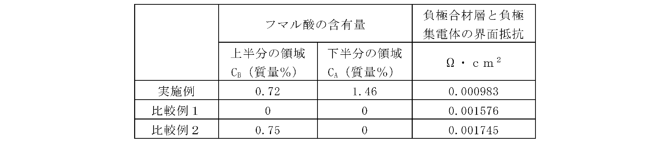
[負極活物質の粒子同士の結着力(密着力)の測定]
レスカ社製のタッキング試験機TAC-IIを用いて、実施例、比較例1,3の各負極における負極合材層内の負極活物質の粒子同士の結着力(密着力)を測定した。具体的な測定条件等は下記の通りである。作製した負極を所定サイズ(2cm×3cm)にカットしたものを試験サンプルとした。そして、接着面積2mmφの金属棒の先端に日東製両面テープ#515を貼り、試験サンプルに400gfの予加重で10秒間押さえた後、600mm/minの速さで剥がした。このとき、前記テープ表面に一部の負極活物質の粒子が接着した状態となり、負極合材層内の負極活物質粒子の間で引き剥がされることとなる。この際の、剥がすのに必要な応力を負極合材層内の負極活物質の粒子同士の結着力(密着力)とした。表2に、実施例及び比較例1,3の各負極における負極合材層内の負極活物質の粒子同士の結着力(密着力)の結果をまとめた。但し、表2では、比較例1の負極活物質の粒子同士の結着力(密着力)の値を基準(100)として、他の実施例及び比較例3の負極活物質の粒子同士の結着力(密着力)の値を相対値として示している。 [Measurement of adhesion (binding strength) between particles of negative electrode active material]
Using a tacking tester TAC-II manufactured by Rhesca, the binding force (adhesion force) between the particles of the negative electrode active material in the negative electrode mixture layer in each of the negative electrodes of the Example, Comparative Examples 1 and 3 was measured. Specific measurement conditions are as follows. The prepared negative electrode was cut to a predetermined size (2 cm x 3 cm) to be used as a test sample. Then, Nitto double-sided tape #515 was attached to the tip of a metal bar with an adhesive area of 2 mmφ, and the test sample was pressed with a preload of 400 gf for 10 seconds, and then peeled off at a speed of 600 mm/min. At this time, some of the particles of the negative electrode active material were adhered to the surface of the tape, and were peeled off between the particles of the negative electrode active material in the negative electrode mixture layer. The stress required for peeling at this time was taken as the binding force (adhesion force) between the particles of the negative electrode active material in the negative electrode mixture layer. Table 2 summarizes the results of the binding force (adhesion force) between the particles of the negative electrode active material in the negative electrode mixture layer in each of the negative electrodes of the Example and Comparative Examples 1 and 3. However, in Table 2, the value of the binding strength (adhesion strength) between particles of the negative electrode active material in Comparative Example 1 is set as the reference (100), and the values of the binding strength (adhesion strength) between particles of the negative electrode active material in other Examples and Comparative Example 3 are shown as relative values.

負極合材層において、下半分の領域中のジカルボン酸成分の含有量(CA)と、上半分の領域中のジカルボン酸成分の含有量(CB)とが、CA>CBの関係を満たす実施例は、ジカルボン酸成分を含まない比較例1と比べて、負極合材層と負極集電体との界面抵抗は減少し、負極合材層内の負極活物質の粒子同士の結着力(密着力)は同程度であった。なお、CA<CBの関係を満たす比較例2は、比較例1と比べて、負極合材層と負極集電体との界面抵抗の減少は見られず、同程度であった。また、下半分の領域及び上半分の領域の両方にジカルボン酸成分を含むが、CA=CBの関係を満たす比較例3は、比較例1と比べて、負極合材層内の負極活物質の粒子同士の結着力(密着力)が15%も低下した。
In the negative electrode mixture layer, the content of the dicarboxylic acid component in the lower half region (C A ) and the content of the dicarboxylic acid component in the upper half region (C B ) satisfy the relationship of C A > C B. In the example, the interface resistance between the negative electrode mixture layer and the negative electrode current collector was reduced compared to Comparative Example 1, which does not contain a dicarboxylic acid component, and the binding force (adhesion) between the particles of the negative electrode active material in the negative electrode mixture layer was about the same. In addition, in Comparative Example 2, which satisfies the relationship of C A < C B , the interface resistance between the negative electrode mixture layer and the negative electrode current collector was not reduced and was about the same compared to Comparative Example 1. In addition, in Comparative Example 3, which contains a dicarboxylic acid component in both the lower half region and the upper half region but satisfies the relationship of C A = C B , the binding force (adhesion) between the particles of the negative electrode active material in the negative electrode mixture layer was reduced by 15% compared to Comparative Example 1.
[付記]
(1)
負極集電体と、前記負極集電体上に設けられた負極合材層と、を備え、
前記負極合材層は、負極活物質と、ジカルボン酸及びその無水物のうちの少なくともいずれか一方を含むジカルボン酸成分と、を有し、
前記負極合材層を厚み方向において2等分して、前記負極集電体側の下半分の領域と表面側の上半分の領域とに分けた場合、前記下半分の領域中の前記ジカルボン酸成分の含有量(CA)と、前記上半分の領域中の前記ジカルボン酸成分の含有量(CB)とが、CA>CBの関係を満たす、二次電池用負極。
(2)
前記下半分の領域中の前記ジカルボン酸成分の含有量(CA)に対する前記上半分の領域中の前記ジカルボン酸成分の含有量(CB)の比(CB/CA)は0以上、0.7以下である、上記(1)に記載の二次電池用負極。
(3)
前記下半分の領域中の前記ジカルボン酸成分の含有量(CA)に対する前記上半分の領域中の前記ジカルボン酸成分の含有量(CB)の比(CB/CA)は0以上、0.5以下である、上記(2)に記載の二次電池用負極。
(4)
前記下半分の領域中の前記ジカルボン酸成分の含有量(CA)は、0.1質量%以上、2質量%以下である、上記(1)~(3)のいずれか1つに記載の二次電池用負極。
(5)
前記下半分の領域中の前記ジカルボン酸成分の含有量(CA)は、0.4質量%以上、1.5質量%以下である、上記(1)~(4)のいずれか1つに記載の二次電池用負極。
(6)
前記上半分の領域中の前記ジカルボン酸成分の含有量(CB)は、0質量%以上、1.4質量%以下である、上記(1)~(5)のいずれか1つに記載の二次電池用負極。
(7)
前記ジカルボン酸は不飽和ジカルボン酸である、上記(1)~(6)のいずれか1つに記載の二次電池用負極。
(8)
前記負極活物質は、黒鉛材料及びSi含有材料を含む、上記(1)~(7)のいずれか1つに記載の二次電池用負極。
(9)
前記不飽和ジカルボン酸は、フマル酸、メサコン酸及びメチレンコハク酸のうちの少なくともいずれか1つを含む、上記(7)に記載の二次電池用負極。
(10)
Si含有材料は、炭素相と、前記炭素相内に分散しているシリコン相とを有する第1複合粒子、シリケート相と、前記シリケート相内に分散しているシリコン相とを有する第2複合粒子、酸化シリコン相と、前記酸化シリコン相内に分散しているシリコン相とを有する第3複合粒子のうちの少なくともいずれか1つを含む、上記(1)~(9)のいずれか1つに記載の二次電池用負極。
(11)
前記第2複合粒子の前記シリケート相は、式:Li2zSiO(2+z)(0<z<2)で表されるリチウムシリケート相を含む、上記(10)に記載の二次電池用負極。
(12)
上記(1)~(11)のいずれか1つに記載の二次電池用負極を備える、二次電池。 [Additional Notes]
(1)
a negative electrode current collector; and a negative electrode mixture layer provided on the negative electrode current collector,
The negative electrode mixture layer has a negative electrode active material and a dicarboxylic acid component including at least one of a dicarboxylic acid and an anhydride thereof,
When the negative electrode mixture layer is divided into two equal parts in the thickness direction into a lower half region on the negative electrode current collector side and an upper half region on the surface side, the content of the dicarboxylic acid component in the lower half region (C A ) and the content of the dicarboxylic acid component in the upper half region (C B ) satisfy the relationship C A > C B.
(2)
The negative electrode for secondary batteries according to the above (1), wherein a ratio ( CB / CA ) of a content ( CB ) of the dicarboxylic acid component in the upper half region to a content ( CA ) of the dicarboxylic acid component in the lower half region is 0 or more and 0.7 or less.
(3)
The negative electrode for secondary batteries according to the above (2), wherein a ratio ( CB / CA ) of a content ( CB ) of the dicarboxylic acid component in the upper half region to a content ( CA ) of the dicarboxylic acid component in the lower half region is 0 or more and 0.5 or less.
(4)
The negative electrode for secondary batteries according to any one of (1) to (3) above, wherein the content (C A ) of the dicarboxylic acid component in the lower half region is 0.1 mass % or more and 2 mass % or less.
(5)
The negative electrode for secondary batteries according to any one of (1) to (4) above, wherein the content (C A ) of the dicarboxylic acid component in the lower half region is 0.4 mass % or more and 1.5 mass % or less.
(6)
The negative electrode for secondary batteries according to any one of (1) to (5) above, wherein the content (C B ) of the dicarboxylic acid component in the upper half region is 0 mass % or more and 1.4 mass % or less.
(7)
The negative electrode for secondary batteries according to any one of (1) to (6) above, wherein the dicarboxylic acid is an unsaturated dicarboxylic acid.
(8)
The negative electrode for a secondary battery according to any one of (1) to (7) above, wherein the negative electrode active material contains a graphite material and a Si-containing material.
(9)
The negative electrode for a secondary battery according to (7) above, wherein the unsaturated dicarboxylic acid includes at least one of fumaric acid, mesaconic acid, and methylene succinic acid.
(10)
The negative electrode for a secondary battery according to any one of (1) to (9) above, wherein the Si-containing material includes at least one of a first composite particle having a carbon phase and a silicon phase dispersed in the carbon phase, a second composite particle having a silicate phase and a silicon phase dispersed in the silicate phase, and a third composite particle having a silicon oxide phase and a silicon phase dispersed in the silicon oxide phase.
(11)
The negative electrode for a secondary battery according to (10) above, wherein the silicate phase of the second composite particles contains a lithium silicate phase represented by the formula Li 2z SiO (2+z) (0<z<2).
(12)
A secondary battery comprising the negative electrode for secondary batteries according to any one of (1) to (11) above.
(1)
負極集電体と、前記負極集電体上に設けられた負極合材層と、を備え、
前記負極合材層は、負極活物質と、ジカルボン酸及びその無水物のうちの少なくともいずれか一方を含むジカルボン酸成分と、を有し、
前記負極合材層を厚み方向において2等分して、前記負極集電体側の下半分の領域と表面側の上半分の領域とに分けた場合、前記下半分の領域中の前記ジカルボン酸成分の含有量(CA)と、前記上半分の領域中の前記ジカルボン酸成分の含有量(CB)とが、CA>CBの関係を満たす、二次電池用負極。
(2)
前記下半分の領域中の前記ジカルボン酸成分の含有量(CA)に対する前記上半分の領域中の前記ジカルボン酸成分の含有量(CB)の比(CB/CA)は0以上、0.7以下である、上記(1)に記載の二次電池用負極。
(3)
前記下半分の領域中の前記ジカルボン酸成分の含有量(CA)に対する前記上半分の領域中の前記ジカルボン酸成分の含有量(CB)の比(CB/CA)は0以上、0.5以下である、上記(2)に記載の二次電池用負極。
(4)
前記下半分の領域中の前記ジカルボン酸成分の含有量(CA)は、0.1質量%以上、2質量%以下である、上記(1)~(3)のいずれか1つに記載の二次電池用負極。
(5)
前記下半分の領域中の前記ジカルボン酸成分の含有量(CA)は、0.4質量%以上、1.5質量%以下である、上記(1)~(4)のいずれか1つに記載の二次電池用負極。
(6)
前記上半分の領域中の前記ジカルボン酸成分の含有量(CB)は、0質量%以上、1.4質量%以下である、上記(1)~(5)のいずれか1つに記載の二次電池用負極。
(7)
前記ジカルボン酸は不飽和ジカルボン酸である、上記(1)~(6)のいずれか1つに記載の二次電池用負極。
(8)
前記負極活物質は、黒鉛材料及びSi含有材料を含む、上記(1)~(7)のいずれか1つに記載の二次電池用負極。
(9)
前記不飽和ジカルボン酸は、フマル酸、メサコン酸及びメチレンコハク酸のうちの少なくともいずれか1つを含む、上記(7)に記載の二次電池用負極。
(10)
Si含有材料は、炭素相と、前記炭素相内に分散しているシリコン相とを有する第1複合粒子、シリケート相と、前記シリケート相内に分散しているシリコン相とを有する第2複合粒子、酸化シリコン相と、前記酸化シリコン相内に分散しているシリコン相とを有する第3複合粒子のうちの少なくともいずれか1つを含む、上記(1)~(9)のいずれか1つに記載の二次電池用負極。
(11)
前記第2複合粒子の前記シリケート相は、式:Li2zSiO(2+z)(0<z<2)で表されるリチウムシリケート相を含む、上記(10)に記載の二次電池用負極。
(12)
上記(1)~(11)のいずれか1つに記載の二次電池用負極を備える、二次電池。 [Additional Notes]
(1)
a negative electrode current collector; and a negative electrode mixture layer provided on the negative electrode current collector,
The negative electrode mixture layer has a negative electrode active material and a dicarboxylic acid component including at least one of a dicarboxylic acid and an anhydride thereof,
When the negative electrode mixture layer is divided into two equal parts in the thickness direction into a lower half region on the negative electrode current collector side and an upper half region on the surface side, the content of the dicarboxylic acid component in the lower half region (C A ) and the content of the dicarboxylic acid component in the upper half region (C B ) satisfy the relationship C A > C B.
(2)
The negative electrode for secondary batteries according to the above (1), wherein a ratio ( CB / CA ) of a content ( CB ) of the dicarboxylic acid component in the upper half region to a content ( CA ) of the dicarboxylic acid component in the lower half region is 0 or more and 0.7 or less.
(3)
The negative electrode for secondary batteries according to the above (2), wherein a ratio ( CB / CA ) of a content ( CB ) of the dicarboxylic acid component in the upper half region to a content ( CA ) of the dicarboxylic acid component in the lower half region is 0 or more and 0.5 or less.
(4)
The negative electrode for secondary batteries according to any one of (1) to (3) above, wherein the content (C A ) of the dicarboxylic acid component in the lower half region is 0.1 mass % or more and 2 mass % or less.
(5)
The negative electrode for secondary batteries according to any one of (1) to (4) above, wherein the content (C A ) of the dicarboxylic acid component in the lower half region is 0.4 mass % or more and 1.5 mass % or less.
(6)
The negative electrode for secondary batteries according to any one of (1) to (5) above, wherein the content (C B ) of the dicarboxylic acid component in the upper half region is 0 mass % or more and 1.4 mass % or less.
(7)
The negative electrode for secondary batteries according to any one of (1) to (6) above, wherein the dicarboxylic acid is an unsaturated dicarboxylic acid.
(8)
The negative electrode for a secondary battery according to any one of (1) to (7) above, wherein the negative electrode active material contains a graphite material and a Si-containing material.
(9)
The negative electrode for a secondary battery according to (7) above, wherein the unsaturated dicarboxylic acid includes at least one of fumaric acid, mesaconic acid, and methylene succinic acid.
(10)
The negative electrode for a secondary battery according to any one of (1) to (9) above, wherein the Si-containing material includes at least one of a first composite particle having a carbon phase and a silicon phase dispersed in the carbon phase, a second composite particle having a silicate phase and a silicon phase dispersed in the silicate phase, and a third composite particle having a silicon oxide phase and a silicon phase dispersed in the silicon oxide phase.
(11)
The negative electrode for a secondary battery according to (10) above, wherein the silicate phase of the second composite particles contains a lithium silicate phase represented by the formula Li 2z SiO (2+z) (0<z<2).
(12)
A secondary battery comprising the negative electrode for secondary batteries according to any one of (1) to (11) above.
10 二次電池、11 正極、12 負極、13 セパレータ、14 電極体、15 電池ケース、16 ケース本体、17 封口体、18,19 絶縁板、20 正極リード、21 負極リード、22 張り出し部、23 フィルタ、24 下弁体、25 絶縁部材、26 上弁体、27 キャップ、28 ガスケット、40 負極集電体、42 負極合材層、42a 下半分の領域、42b 上半分の領域。
10 secondary battery, 11 positive electrode, 12 negative electrode, 13 separator, 14 electrode body, 15 battery case, 16 case body, 17 sealing body, 18, 19 insulating plate, 20 positive electrode lead, 21 negative electrode lead, 22 protruding portion, 23 filter, 24 lower valve body, 25 insulating member, 26 upper valve body, 27 cap, 28 gasket, 40 negative electrode current collector, 42 negative electrode composite layer, 42a lower half region, 42b upper half region.
Claims (12)
- 負極集電体と、前記負極集電体上に設けられた負極合材層と、を備え、
前記負極合材層は、負極活物質と、ジカルボン酸及びその無水物のうちの少なくともいずれか一方を含むジカルボン酸成分と、を有し、
前記負極合材層を厚み方向において2等分して、前記負極集電体側の下半分の領域と表面側の上半分の領域とに分けた場合、前記下半分の領域中の前記ジカルボン酸成分の含有量(CA)と、前記上半分の領域中の前記ジカルボン酸成分の含有量(CB)とが、CA>CBの関係を満たす、二次電池用負極。 a negative electrode current collector; and a negative electrode mixture layer provided on the negative electrode current collector,
The negative electrode mixture layer has a negative electrode active material and a dicarboxylic acid component including at least one of a dicarboxylic acid and an anhydride thereof,
When the negative electrode mixture layer is divided into two equal parts in the thickness direction into a lower half region on the negative electrode current collector side and an upper half region on the surface side, the content of the dicarboxylic acid component in the lower half region (C A ) and the content of the dicarboxylic acid component in the upper half region (C B ) satisfy the relationship C A >C B. - 前記下半分の領域中の前記ジカルボン酸成分の含有量(CA)に対する前記上半分の領域中の前記ジカルボン酸成分の含有量(CB)の比(CB/CA)は0以上、0.7以下である、請求項1に記載の二次電池用負極。 2. The negative electrode for secondary batteries according to claim 1, wherein a ratio ( CB / CA ) of a content ( CB ) of the dicarboxylic acid component in the upper half region to a content ( CA ) of the dicarboxylic acid component in the lower half region is 0 or more and 0.7 or less.
- 前記下半分の領域中の前記ジカルボン酸成分の含有量(CA)に対する前記上半分の領域中の前記ジカルボン酸成分の含有量(CB)の比(CB/CA)は0以上、0.5以下である、請求項2に記載の二次電池用負極。 3. The negative electrode for secondary batteries according to claim 2, wherein a ratio ( CB / CA ) of a content ( CB ) of the dicarboxylic acid component in the upper half region to a content ( CA ) of the dicarboxylic acid component in the lower half region is 0 or more and 0.5 or less.
- 前記下半分の領域中の前記ジカルボン酸成分の含有量(CA)は、0.1質量%以上、2質量%以下である、請求項1~3のいずれか1項に記載の二次電池用負極。 4. The negative electrode for secondary batteries according to claim 1, wherein the content (C A ) of the dicarboxylic acid component in the lower half region is 0.1 mass % or more and 2 mass % or less.
- 前記下半分の領域中の前記ジカルボン酸成分の含有量(CA)は、0.4質量%以上、1.5質量%以下である、請求項1~3のいずれか1項に記載の二次電池用負極。 4. The negative electrode for secondary batteries according to claim 1, wherein the content (C A ) of the dicarboxylic acid component in the lower half region is 0.4 mass % or more and 1.5 mass % or less.
- 前記上半分の領域中の前記ジカルボン酸成分の含有量(CB)は、0質量%以上、1.4質量%以下である、請求項1~3のいずれか1項に記載の二次電池用負極。 4. The negative electrode for secondary batteries according to claim 1, wherein the content (C B ) of the dicarboxylic acid component in the upper half region is 0 mass % or more and 1.4 mass % or less.
- 前記ジカルボン酸は不飽和ジカルボン酸である、請求項1~3のいずれか1項に記載の二次電池用負極。 The negative electrode for a secondary battery according to any one of claims 1 to 3, wherein the dicarboxylic acid is an unsaturated dicarboxylic acid.
- 前記負極活物質は、黒鉛材料及びSi含有材料を含む、請求項1~3のいずれか1項に記載の二次電池用負極。 The negative electrode for a secondary battery according to any one of claims 1 to 3, wherein the negative electrode active material includes a graphite material and a Si-containing material.
- 前記不飽和ジカルボン酸は、フマル酸、メサコン酸及びメチレンコハク酸のうちの少なくともいずれか1つを含む、請求項7に記載の二次電池用負極。 The negative electrode for a secondary battery according to claim 7, wherein the unsaturated dicarboxylic acid includes at least one of fumaric acid, mesaconic acid, and methylene succinic acid.
- Si含有材料は、炭素相と、前記炭素相内に分散しているシリコン相とを有する第1複合粒子、シリケート相と、前記シリケート相内に分散しているシリコン相とを有する第2複合粒子、酸化シリコン相と、前記酸化シリコン相内に分散しているシリコン相とを有する第3複合粒子のうちの少なくともいずれか1つを含む、請求項1~3のいずれか1項に記載の二次電池用負極。 The negative electrode for a secondary battery according to any one of claims 1 to 3, wherein the Si-containing material includes at least one of a first composite particle having a carbon phase and a silicon phase dispersed within the carbon phase, a second composite particle having a silicate phase and a silicon phase dispersed within the silicate phase, and a third composite particle having a silicon oxide phase and a silicon phase dispersed within the silicon oxide phase.
- 前記第2複合粒子の前記シリケート相は、式:Li2zSiO(2+z)(0<z<2)で表されるリチウムシリケート相を含む、請求項10に記載の二次電池用負極。 The negative electrode for a secondary battery according to claim 10 , wherein the silicate phase of the second composite particles includes a lithium silicate phase represented by the formula Li 2z SiO (2+z) (0<z<2).
- 請求項1~3のいずれか1項に記載の二次電池用負極を備える、二次電池。 A secondary battery comprising the negative electrode for a secondary battery according to any one of claims 1 to 3.
Applications Claiming Priority (2)
| Application Number | Priority Date | Filing Date | Title |
|---|---|---|---|
| JP2022-170929 | 2022-10-25 | ||
| JP2022170929 | 2022-10-25 |
Publications (1)
| Publication Number | Publication Date |
|---|---|
| WO2024090206A1 true WO2024090206A1 (en) | 2024-05-02 |
Family
ID=90830753
Family Applications (1)
| Application Number | Title | Priority Date | Filing Date |
|---|---|---|---|
| PCT/JP2023/036845 WO2024090206A1 (en) | 2022-10-25 | 2023-10-11 | Negative electrode for secondary battery, and secondary battery |
Country Status (1)
| Country | Link |
|---|---|
| WO (1) | WO2024090206A1 (en) |
Citations (8)
| Publication number | Priority date | Publication date | Assignee | Title |
|---|---|---|---|---|
| JP2004006188A (en) * | 2002-04-10 | 2004-01-08 | Sony Corp | Non-aqueous electrolyte battery |
| CN101436677A (en) * | 2007-11-12 | 2009-05-20 | 比亚迪股份有限公司 | Method for preparing battery |
| JP2016110900A (en) * | 2014-12-09 | 2016-06-20 | 三星エスディアイ株式会社Samsung SDI Co., Ltd. | Lithium ion secondary battery |
| WO2019009239A1 (en) * | 2017-07-03 | 2019-01-10 | 株式会社村田製作所 | Secondary battery, battery pack, electric vehicle, power storage system, power tool, and electronic device |
| WO2020203420A1 (en) * | 2019-03-29 | 2020-10-08 | パナソニックIpマネジメント株式会社 | Nonaqueous electrolyte secondary battery |
| JP2020184473A (en) * | 2019-05-09 | 2020-11-12 | 株式会社クラレ | Method for producing negative electrode active material composite for nonaqueous secondary battery |
| WO2021172443A1 (en) * | 2020-02-28 | 2021-09-02 | パナソニックIpマネジメント株式会社 | Secondary-battery negative electrode, method for manufacturing same, and secondary battery |
| WO2021199587A1 (en) * | 2020-03-30 | 2021-10-07 | パナソニックIpマネジメント株式会社 | Negative electrode active material for secondary batteries, and secondary battery using same |
-
2023
- 2023-10-11 WO PCT/JP2023/036845 patent/WO2024090206A1/en unknown
Patent Citations (8)
| Publication number | Priority date | Publication date | Assignee | Title |
|---|---|---|---|---|
| JP2004006188A (en) * | 2002-04-10 | 2004-01-08 | Sony Corp | Non-aqueous electrolyte battery |
| CN101436677A (en) * | 2007-11-12 | 2009-05-20 | 比亚迪股份有限公司 | Method for preparing battery |
| JP2016110900A (en) * | 2014-12-09 | 2016-06-20 | 三星エスディアイ株式会社Samsung SDI Co., Ltd. | Lithium ion secondary battery |
| WO2019009239A1 (en) * | 2017-07-03 | 2019-01-10 | 株式会社村田製作所 | Secondary battery, battery pack, electric vehicle, power storage system, power tool, and electronic device |
| WO2020203420A1 (en) * | 2019-03-29 | 2020-10-08 | パナソニックIpマネジメント株式会社 | Nonaqueous electrolyte secondary battery |
| JP2020184473A (en) * | 2019-05-09 | 2020-11-12 | 株式会社クラレ | Method for producing negative electrode active material composite for nonaqueous secondary battery |
| WO2021172443A1 (en) * | 2020-02-28 | 2021-09-02 | パナソニックIpマネジメント株式会社 | Secondary-battery negative electrode, method for manufacturing same, and secondary battery |
| WO2021199587A1 (en) * | 2020-03-30 | 2021-10-07 | パナソニックIpマネジメント株式会社 | Negative electrode active material for secondary batteries, and secondary battery using same |
Similar Documents
| Publication | Publication Date | Title |
|---|---|---|
| JP4487220B1 (en) | Positive electrode for lithium secondary battery and method for producing the same | |
| JP5158452B2 (en) | Positive electrode for lithium secondary battery and its utilization | |
| JP5773208B2 (en) | Lithium secondary battery | |
| JP5773209B2 (en) | Lithium secondary battery | |
| JP5748108B2 (en) | Lithium secondary battery | |
| WO2018225515A1 (en) | Negative electrode for nonaqueous electrolyte secondary batteries, and nonaqueous electrolyte secondary battery | |
| JP2017183051A (en) | Negative electrode active material for lithium ion secondary battery, lithium ion secondary battery negative electrode arranged by use thereof, and lithium ion secondary battery arranged by use thereof | |
| WO2019107067A1 (en) | Nonaqueous electrolyte secondary battery | |
| WO2011108119A1 (en) | Lithium secondary battery and separator for use in said battery | |
| JP5297109B2 (en) | Nonaqueous electrolyte secondary battery | |
| JP2011028898A (en) | Positive electrode for lithium secondary battery and method of manufacturing the same | |
| JP7150448B2 (en) | ELECTRODE FOR LITHIUM-ION SECONDARY BATTERY, MANUFACTURING METHOD THEREOF, AND LITHIUM-ION SECONDARY BATTERY | |
| JP2010251047A (en) | Manufacturing method of cathode | |
| WO2020213499A1 (en) | Negative electrode for non-aqueous electrolyte secondary battery and non-aqueous electrolyte secondary battery | |
| WO2020044931A1 (en) | Negative electrode active material for nonaqueous electrolyte secondary batteries, negative electrode for nonaqueous electrolyte secondary batteries, and nonaqueous electrolyte secondary battery | |
| JP2014022245A (en) | Lithium ion secondary battery and manufacturing method thereof | |
| WO2024090206A1 (en) | Negative electrode for secondary battery, and secondary battery | |
| JP2020126733A (en) | Electrode for lithium ion secondary battery and lithium ion secondary battery | |
| WO2021241027A1 (en) | Positive electrode active material for nonaqueous electrolyte secondary batteries, and nonaqueous electrolyte secondary battery | |
| JP2011134589A (en) | Manufacturing method of electrode for secondary battery | |
| US10211456B2 (en) | Positive electrode active material for lithium ion secondary battery, and lithium ion secondary battery positive electrode and lithium ion secondary battery using the same | |
| WO2023053842A1 (en) | Negative electrode for secondary batteries, and secondary battery | |
| WO2022230661A1 (en) | Secondary battery negative electrode, secondary battery, and method for manufacturing secondary battery negative electrode | |
| WO2023181912A1 (en) | Positive electrode for non-aqueous electrolyte secondary battery, and non-aqueous electrolyte secondary battery | |
| WO2024048183A1 (en) | Negative electrode for secondary batteries, secondary battery, and method for producing negative electrode for secondary batteries |