JP5773209B2 - Lithium secondary battery - Google Patents
Lithium secondary battery Download PDFInfo
- Publication number
- JP5773209B2 JP5773209B2 JP2011550754A JP2011550754A JP5773209B2 JP 5773209 B2 JP5773209 B2 JP 5773209B2 JP 2011550754 A JP2011550754 A JP 2011550754A JP 2011550754 A JP2011550754 A JP 2011550754A JP 5773209 B2 JP5773209 B2 JP 5773209B2
- Authority
- JP
- Japan
- Prior art keywords
- positive electrode
- secondary battery
- lithium secondary
- pore
- mixture layer
- Prior art date
- Legal status (The legal status is an assumption and is not a legal conclusion. Google has not performed a legal analysis and makes no representation as to the accuracy of the status listed.)
- Active
Links
- 229910052744 lithium Inorganic materials 0.000 title claims description 109
- WHXSMMKQMYFTQS-UHFFFAOYSA-N Lithium Chemical compound [Li] WHXSMMKQMYFTQS-UHFFFAOYSA-N 0.000 title claims description 95
- 239000011148 porous material Substances 0.000 claims description 194
- 239000000203 mixture Substances 0.000 claims description 106
- 238000009826 distribution Methods 0.000 claims description 44
- 239000007774 positive electrode material Substances 0.000 claims description 30
- 239000002245 particle Substances 0.000 claims description 28
- OKTJSMMVPCPJKN-UHFFFAOYSA-N Carbon Chemical compound [C] OKTJSMMVPCPJKN-UHFFFAOYSA-N 0.000 claims description 22
- 239000004020 conductor Substances 0.000 claims description 22
- 238000004519 manufacturing process Methods 0.000 claims description 19
- -1 lithium transition metal Chemical class 0.000 claims description 15
- 229910052723 transition metal Inorganic materials 0.000 claims description 13
- 238000005259 measurement Methods 0.000 claims description 10
- QSHDDOUJBYECFT-UHFFFAOYSA-N mercury Chemical compound [Hg] QSHDDOUJBYECFT-UHFFFAOYSA-N 0.000 claims description 10
- 229910052753 mercury Inorganic materials 0.000 claims description 10
- 239000002905 metal composite material Substances 0.000 claims description 8
- 239000006230 acetylene black Substances 0.000 claims description 4
- 239000006232 furnace black Substances 0.000 claims description 3
- 239000003273 ketjen black Substances 0.000 claims description 3
- 239000010410 layer Substances 0.000 description 95
- 239000000463 material Substances 0.000 description 25
- 239000011255 nonaqueous electrolyte Substances 0.000 description 19
- HBBGRARXTFLTSG-UHFFFAOYSA-N Lithium ion Chemical compound [Li+] HBBGRARXTFLTSG-UHFFFAOYSA-N 0.000 description 17
- 229910001416 lithium ion Inorganic materials 0.000 description 17
- PXHVJJICTQNCMI-UHFFFAOYSA-N nickel Substances [Ni] PXHVJJICTQNCMI-UHFFFAOYSA-N 0.000 description 17
- 239000003125 aqueous solvent Substances 0.000 description 15
- 239000011230 binding agent Substances 0.000 description 14
- 238000000034 method Methods 0.000 description 13
- 239000002904 solvent Substances 0.000 description 12
- 229910052751 metal Inorganic materials 0.000 description 11
- 238000012360 testing method Methods 0.000 description 10
- 239000008151 electrolyte solution Substances 0.000 description 9
- 229910052759 nickel Inorganic materials 0.000 description 9
- XLYOFNOQVPJJNP-UHFFFAOYSA-N water Substances O XLYOFNOQVPJJNP-UHFFFAOYSA-N 0.000 description 9
- SECXISVLQFMRJM-UHFFFAOYSA-N N-Methylpyrrolidone Chemical compound CN1CCCC1=O SECXISVLQFMRJM-UHFFFAOYSA-N 0.000 description 8
- 239000011572 manganese Substances 0.000 description 8
- 239000007773 negative electrode material Substances 0.000 description 8
- 239000002131 composite material Substances 0.000 description 7
- 239000002184 metal Substances 0.000 description 6
- 230000000717 retained effect Effects 0.000 description 6
- 229920003048 styrene butadiene rubber Polymers 0.000 description 6
- RYGMFSIKBFXOCR-UHFFFAOYSA-N Copper Chemical compound [Cu] RYGMFSIKBFXOCR-UHFFFAOYSA-N 0.000 description 5
- 239000002800 charge carrier Substances 0.000 description 5
- 239000011248 coating agent Substances 0.000 description 5
- 238000000576 coating method Methods 0.000 description 5
- 239000000470 constituent Substances 0.000 description 5
- 239000003792 electrolyte Substances 0.000 description 5
- 239000010439 graphite Substances 0.000 description 5
- 229910002804 graphite Inorganic materials 0.000 description 5
- 229920000642 polymer Polymers 0.000 description 5
- 239000000843 powder Substances 0.000 description 5
- KMTRUDSVKNLOMY-UHFFFAOYSA-N Ethylene carbonate Chemical compound O=C1OCCO1 KMTRUDSVKNLOMY-UHFFFAOYSA-N 0.000 description 4
- 239000002033 PVDF binder Substances 0.000 description 4
- 239000002174 Styrene-butadiene Substances 0.000 description 4
- 229910052782 aluminium Inorganic materials 0.000 description 4
- XAGFODPZIPBFFR-UHFFFAOYSA-N aluminium Chemical compound [Al] XAGFODPZIPBFFR-UHFFFAOYSA-N 0.000 description 4
- 239000003575 carbonaceous material Substances 0.000 description 4
- 150000001875 compounds Chemical class 0.000 description 4
- 230000006835 compression Effects 0.000 description 4
- 238000007906 compression Methods 0.000 description 4
- 239000010949 copper Substances 0.000 description 4
- JBTWLSYIZRCDFO-UHFFFAOYSA-N ethyl methyl carbonate Chemical compound CCOC(=O)OC JBTWLSYIZRCDFO-UHFFFAOYSA-N 0.000 description 4
- 229910052748 manganese Inorganic materials 0.000 description 4
- 229920002981 polyvinylidene fluoride Polymers 0.000 description 4
- 229920005989 resin Polymers 0.000 description 4
- 239000011347 resin Substances 0.000 description 4
- 150000003839 salts Chemical class 0.000 description 4
- 235000002639 sodium chloride Nutrition 0.000 description 4
- ZWEHNKRNPOVVGH-UHFFFAOYSA-N 2-Butanone Chemical compound CCC(C)=O ZWEHNKRNPOVVGH-UHFFFAOYSA-N 0.000 description 3
- 229920002134 Carboxymethyl cellulose Polymers 0.000 description 3
- 229910013716 LiNi Inorganic materials 0.000 description 3
- PWHULOQIROXLJO-UHFFFAOYSA-N Manganese Chemical compound [Mn] PWHULOQIROXLJO-UHFFFAOYSA-N 0.000 description 3
- YXFVVABEGXRONW-UHFFFAOYSA-N Toluene Chemical compound CC1=CC=CC=C1 YXFVVABEGXRONW-UHFFFAOYSA-N 0.000 description 3
- 230000015572 biosynthetic process Effects 0.000 description 3
- 229920001577 copolymer Polymers 0.000 description 3
- 229910052802 copper Inorganic materials 0.000 description 3
- 238000001035 drying Methods 0.000 description 3
- 239000011888 foil Substances 0.000 description 3
- 239000000446 fuel Substances 0.000 description 3
- 239000012046 mixed solvent Substances 0.000 description 3
- 238000004804 winding Methods 0.000 description 3
- 229920000049 Carbon (fiber) Polymers 0.000 description 2
- 229920000623 Cellulose acetate phthalate Polymers 0.000 description 2
- OIFBSDVPJOWBCH-UHFFFAOYSA-N Diethyl carbonate Chemical compound CCOC(=O)OCC OIFBSDVPJOWBCH-UHFFFAOYSA-N 0.000 description 2
- 229920002153 Hydroxypropyl cellulose Polymers 0.000 description 2
- XEEYBQQBJWHFJM-UHFFFAOYSA-N Iron Chemical compound [Fe] XEEYBQQBJWHFJM-UHFFFAOYSA-N 0.000 description 2
- 229910013870 LiPF 6 Inorganic materials 0.000 description 2
- 229920003171 Poly (ethylene oxide) Polymers 0.000 description 2
- 239000004372 Polyvinyl alcohol Substances 0.000 description 2
- 229910045601 alloy Inorganic materials 0.000 description 2
- 239000000956 alloy Substances 0.000 description 2
- 239000011575 calcium Substances 0.000 description 2
- 229910052799 carbon Inorganic materials 0.000 description 2
- 239000004917 carbon fiber Substances 0.000 description 2
- 239000001768 carboxy methyl cellulose Substances 0.000 description 2
- 235000010948 carboxy methyl cellulose Nutrition 0.000 description 2
- 239000008112 carboxymethyl-cellulose Substances 0.000 description 2
- 229940081734 cellulose acetate phthalate Drugs 0.000 description 2
- 239000011651 chromium Substances 0.000 description 2
- 229910017052 cobalt Inorganic materials 0.000 description 2
- 239000010941 cobalt Substances 0.000 description 2
- GUTLYIVDDKVIGB-UHFFFAOYSA-N cobalt atom Chemical compound [Co] GUTLYIVDDKVIGB-UHFFFAOYSA-N 0.000 description 2
- 238000010276 construction Methods 0.000 description 2
- 239000011889 copper foil Substances 0.000 description 2
- 238000013461 design Methods 0.000 description 2
- 238000010586 diagram Methods 0.000 description 2
- IEJIGPNLZYLLBP-UHFFFAOYSA-N dimethyl carbonate Chemical compound COC(=O)OC IEJIGPNLZYLLBP-UHFFFAOYSA-N 0.000 description 2
- 238000007599 discharging Methods 0.000 description 2
- 229920001971 elastomer Polymers 0.000 description 2
- 229920000840 ethylene tetrafluoroethylene copolymer Polymers 0.000 description 2
- 239000000835 fiber Substances 0.000 description 2
- 239000001863 hydroxypropyl cellulose Substances 0.000 description 2
- 235000010977 hydroxypropyl cellulose Nutrition 0.000 description 2
- 239000001866 hydroxypropyl methyl cellulose Substances 0.000 description 2
- 229920003088 hydroxypropyl methyl cellulose Polymers 0.000 description 2
- 235000010979 hydroxypropyl methyl cellulose Nutrition 0.000 description 2
- UFVKGYZPFZQRLF-UHFFFAOYSA-N hydroxypropyl methyl cellulose Chemical compound OC1C(O)C(OC)OC(CO)C1OC1C(O)C(O)C(OC2C(C(O)C(OC3C(C(O)C(O)C(CO)O3)O)C(CO)O2)O)C(CO)O1 UFVKGYZPFZQRLF-UHFFFAOYSA-N 0.000 description 2
- 229920003132 hydroxypropyl methylcellulose phthalate Polymers 0.000 description 2
- 229940031704 hydroxypropyl methylcellulose phthalate Drugs 0.000 description 2
- 150000002642 lithium compounds Chemical class 0.000 description 2
- RSNHXDVSISOZOB-UHFFFAOYSA-N lithium nickel Chemical compound [Li].[Ni] RSNHXDVSISOZOB-UHFFFAOYSA-N 0.000 description 2
- 239000011777 magnesium Substances 0.000 description 2
- VNWKTOKETHGBQD-UHFFFAOYSA-N methane Chemical compound C VNWKTOKETHGBQD-UHFFFAOYSA-N 0.000 description 2
- 229920000609 methyl cellulose Polymers 0.000 description 2
- 239000001923 methylcellulose Substances 0.000 description 2
- 238000002156 mixing Methods 0.000 description 2
- 239000010955 niobium Substances 0.000 description 2
- 239000002861 polymer material Substances 0.000 description 2
- 229920001343 polytetrafluoroethylene Polymers 0.000 description 2
- 239000004810 polytetrafluoroethylene Substances 0.000 description 2
- 229920002451 polyvinyl alcohol Polymers 0.000 description 2
- 238000002360 preparation method Methods 0.000 description 2
- 238000003825 pressing Methods 0.000 description 2
- RUOJZAUFBMNUDX-UHFFFAOYSA-N propylene carbonate Chemical compound CC1COC(=O)O1 RUOJZAUFBMNUDX-UHFFFAOYSA-N 0.000 description 2
- 239000005060 rubber Substances 0.000 description 2
- 239000000126 substance Substances 0.000 description 2
- 239000010936 titanium Substances 0.000 description 2
- 238000003466 welding Methods 0.000 description 2
- SMZOUWXMTYCWNB-UHFFFAOYSA-N 2-(2-methoxy-5-methylphenyl)ethanamine Chemical compound COC1=CC=C(C)C=C1CCN SMZOUWXMTYCWNB-UHFFFAOYSA-N 0.000 description 1
- NIXOWILDQLNWCW-UHFFFAOYSA-N 2-Propenoic acid Natural products OC(=O)C=C NIXOWILDQLNWCW-UHFFFAOYSA-N 0.000 description 1
- OYPRJOBELJOOCE-UHFFFAOYSA-N Calcium Chemical compound [Ca] OYPRJOBELJOOCE-UHFFFAOYSA-N 0.000 description 1
- 229910052684 Cerium Inorganic materials 0.000 description 1
- VYZAMTAEIAYCRO-UHFFFAOYSA-N Chromium Chemical compound [Cr] VYZAMTAEIAYCRO-UHFFFAOYSA-N 0.000 description 1
- LFQSCWFLJHTTHZ-UHFFFAOYSA-N Ethanol Chemical compound CCO LFQSCWFLJHTTHZ-UHFFFAOYSA-N 0.000 description 1
- 239000001856 Ethyl cellulose Substances 0.000 description 1
- ZZSNKZQZMQGXPY-UHFFFAOYSA-N Ethyl cellulose Chemical compound CCOCC1OC(OC)C(OCC)C(OCC)C1OC1C(O)C(O)C(OC)C(CO)O1 ZZSNKZQZMQGXPY-UHFFFAOYSA-N 0.000 description 1
- YCKRFDGAMUMZLT-UHFFFAOYSA-N Fluorine atom Chemical compound [F] YCKRFDGAMUMZLT-UHFFFAOYSA-N 0.000 description 1
- GYHNNYVSQQEPJS-UHFFFAOYSA-N Gallium Chemical compound [Ga] GYHNNYVSQQEPJS-UHFFFAOYSA-N 0.000 description 1
- 229910015015 LiAsF 6 Inorganic materials 0.000 description 1
- 229910013063 LiBF 4 Inorganic materials 0.000 description 1
- 229910013372 LiC 4 Inorganic materials 0.000 description 1
- 229910013684 LiClO 4 Inorganic materials 0.000 description 1
- 229910013733 LiCo Inorganic materials 0.000 description 1
- 229910010707 LiFePO 4 Inorganic materials 0.000 description 1
- 229910013275 LiMPO Inorganic materials 0.000 description 1
- 229910001228 Li[Ni1/3Co1/3Mn1/3]O2 (NCM 111) Inorganic materials 0.000 description 1
- FYYHWMGAXLPEAU-UHFFFAOYSA-N Magnesium Chemical compound [Mg] FYYHWMGAXLPEAU-UHFFFAOYSA-N 0.000 description 1
- 229910018584 Mn 2-x O 4 Inorganic materials 0.000 description 1
- ZOKXTWBITQBERF-UHFFFAOYSA-N Molybdenum Chemical compound [Mo] ZOKXTWBITQBERF-UHFFFAOYSA-N 0.000 description 1
- 239000004698 Polyethylene Substances 0.000 description 1
- 239000004743 Polypropylene Substances 0.000 description 1
- 239000004793 Polystyrene Substances 0.000 description 1
- FAPWRFPIFSIZLT-UHFFFAOYSA-M Sodium chloride Chemical group [Na+].[Cl-] FAPWRFPIFSIZLT-UHFFFAOYSA-M 0.000 description 1
- ATJFFYVFTNAWJD-UHFFFAOYSA-N Tin Chemical compound [Sn] ATJFFYVFTNAWJD-UHFFFAOYSA-N 0.000 description 1
- RTAQQCXQSZGOHL-UHFFFAOYSA-N Titanium Chemical compound [Ti] RTAQQCXQSZGOHL-UHFFFAOYSA-N 0.000 description 1
- QXZUUHYBWMWJHK-UHFFFAOYSA-N [Co].[Ni] Chemical compound [Co].[Ni] QXZUUHYBWMWJHK-UHFFFAOYSA-N 0.000 description 1
- KLARSDUHONHPRF-UHFFFAOYSA-N [Li].[Mn] Chemical compound [Li].[Mn] KLARSDUHONHPRF-UHFFFAOYSA-N 0.000 description 1
- SOXUFMZTHZXOGC-UHFFFAOYSA-N [Li].[Mn].[Co].[Ni] Chemical compound [Li].[Mn].[Co].[Ni] SOXUFMZTHZXOGC-UHFFFAOYSA-N 0.000 description 1
- 239000011149 active material Substances 0.000 description 1
- 239000000654 additive Substances 0.000 description 1
- 229910002056 binary alloy Inorganic materials 0.000 description 1
- 229910052791 calcium Inorganic materials 0.000 description 1
- 239000006229 carbon black Substances 0.000 description 1
- 235000019241 carbon black Nutrition 0.000 description 1
- 229920002678 cellulose Polymers 0.000 description 1
- 239000001913 cellulose Substances 0.000 description 1
- GWXLDORMOJMVQZ-UHFFFAOYSA-N cerium Chemical compound [Ce] GWXLDORMOJMVQZ-UHFFFAOYSA-N 0.000 description 1
- 239000013626 chemical specie Substances 0.000 description 1
- 229910052804 chromium Inorganic materials 0.000 description 1
- 238000004581 coalescence Methods 0.000 description 1
- CKFRRHLHAJZIIN-UHFFFAOYSA-N cobalt lithium Chemical compound [Li].[Co] CKFRRHLHAJZIIN-UHFFFAOYSA-N 0.000 description 1
- MZZUATUOLXMCEY-UHFFFAOYSA-N cobalt manganese Chemical compound [Mn].[Co] MZZUATUOLXMCEY-UHFFFAOYSA-N 0.000 description 1
- 238000007796 conventional method Methods 0.000 description 1
- 238000002050 diffraction method Methods 0.000 description 1
- 230000000694 effects Effects 0.000 description 1
- 230000005611 electricity Effects 0.000 description 1
- 238000010894 electron beam technology Methods 0.000 description 1
- 229920001249 ethyl cellulose Polymers 0.000 description 1
- 235000019325 ethyl cellulose Nutrition 0.000 description 1
- 238000011156 evaluation Methods 0.000 description 1
- 230000001747 exhibiting effect Effects 0.000 description 1
- 230000002349 favourable effect Effects 0.000 description 1
- 238000010304 firing Methods 0.000 description 1
- 239000011737 fluorine Substances 0.000 description 1
- 229910052731 fluorine Inorganic materials 0.000 description 1
- 229910052733 gallium Inorganic materials 0.000 description 1
- 229910021385 hard carbon Inorganic materials 0.000 description 1
- 125000002887 hydroxy group Chemical group [H]O* 0.000 description 1
- 229910052738 indium Inorganic materials 0.000 description 1
- APFVFJFRJDLVQX-UHFFFAOYSA-N indium atom Chemical compound [In] APFVFJFRJDLVQX-UHFFFAOYSA-N 0.000 description 1
- 238000005342 ion exchange Methods 0.000 description 1
- 150000002500 ions Chemical class 0.000 description 1
- 229910052742 iron Inorganic materials 0.000 description 1
- 150000002576 ketones Chemical class 0.000 description 1
- 239000005001 laminate film Substances 0.000 description 1
- 238000010030 laminating Methods 0.000 description 1
- 238000003475 lamination Methods 0.000 description 1
- 229910052746 lanthanum Inorganic materials 0.000 description 1
- FZLIPJUXYLNCLC-UHFFFAOYSA-N lanthanum atom Chemical compound [La] FZLIPJUXYLNCLC-UHFFFAOYSA-N 0.000 description 1
- 239000004816 latex Substances 0.000 description 1
- 229920000126 latex Polymers 0.000 description 1
- 239000011254 layer-forming composition Substances 0.000 description 1
- 239000007788 liquid Substances 0.000 description 1
- 229910021439 lithium cobalt complex oxide Inorganic materials 0.000 description 1
- 229910021445 lithium manganese complex oxide Inorganic materials 0.000 description 1
- 229910001386 lithium phosphate Inorganic materials 0.000 description 1
- 229910003002 lithium salt Inorganic materials 0.000 description 1
- 159000000002 lithium salts Chemical class 0.000 description 1
- 229910052749 magnesium Inorganic materials 0.000 description 1
- 229910052987 metal hydride Inorganic materials 0.000 description 1
- 229910052750 molybdenum Inorganic materials 0.000 description 1
- 239000011733 molybdenum Substances 0.000 description 1
- 229910052758 niobium Inorganic materials 0.000 description 1
- GUCVJGMIXFAOAE-UHFFFAOYSA-N niobium atom Chemical compound [Nb] GUCVJGMIXFAOAE-UHFFFAOYSA-N 0.000 description 1
- 229910021470 non-graphitizable carbon Inorganic materials 0.000 description 1
- 239000010450 olivine Substances 0.000 description 1
- 229910052609 olivine Inorganic materials 0.000 description 1
- 239000003960 organic solvent Substances 0.000 description 1
- 229920000573 polyethylene Polymers 0.000 description 1
- 229920005672 polyolefin resin Polymers 0.000 description 1
- 229920001155 polypropylene Polymers 0.000 description 1
- 229920002223 polystyrene Polymers 0.000 description 1
- 239000005033 polyvinylidene chloride Substances 0.000 description 1
- 230000002265 prevention Effects 0.000 description 1
- 238000010298 pulverizing process Methods 0.000 description 1
- 239000002994 raw material Substances 0.000 description 1
- 238000000790 scattering method Methods 0.000 description 1
- 238000007789 sealing Methods 0.000 description 1
- VSZWPYCFIRKVQL-UHFFFAOYSA-N selanylidenegallium;selenium Chemical compound [Se].[Se]=[Ga].[Se]=[Ga] VSZWPYCFIRKVQL-UHFFFAOYSA-N 0.000 description 1
- 239000002002 slurry Substances 0.000 description 1
- 159000000000 sodium salts Chemical class 0.000 description 1
- 229910021384 soft carbon Inorganic materials 0.000 description 1
- 229910052596 spinel Chemical group 0.000 description 1
- 239000011029 spinel Chemical group 0.000 description 1
- JBQYATWDVHIOAR-UHFFFAOYSA-N tellanylidenegermanium Chemical compound [Te]=[Ge] JBQYATWDVHIOAR-UHFFFAOYSA-N 0.000 description 1
- 239000002562 thickening agent Substances 0.000 description 1
- 229910052719 titanium Inorganic materials 0.000 description 1
- TWQULNDIKKJZPH-UHFFFAOYSA-K trilithium;phosphate Chemical compound [Li+].[Li+].[Li+].[O-]P([O-])([O-])=O TWQULNDIKKJZPH-UHFFFAOYSA-K 0.000 description 1
- WFKWXMTUELFFGS-UHFFFAOYSA-N tungsten Chemical compound [W] WFKWXMTUELFFGS-UHFFFAOYSA-N 0.000 description 1
- 229910052721 tungsten Inorganic materials 0.000 description 1
- 239000010937 tungsten Substances 0.000 description 1
- LEONUFNNVUYDNQ-UHFFFAOYSA-N vanadium atom Chemical compound [V] LEONUFNNVUYDNQ-UHFFFAOYSA-N 0.000 description 1
- 239000011800 void material Substances 0.000 description 1
Images


Classifications
-
- H—ELECTRICITY
- H01—ELECTRIC ELEMENTS
- H01M—PROCESSES OR MEANS, e.g. BATTERIES, FOR THE DIRECT CONVERSION OF CHEMICAL ENERGY INTO ELECTRICAL ENERGY
- H01M4/00—Electrodes
- H01M4/02—Electrodes composed of, or comprising, active material
- H01M4/13—Electrodes for accumulators with non-aqueous electrolyte, e.g. for lithium-accumulators; Processes of manufacture thereof
-
- H—ELECTRICITY
- H01—ELECTRIC ELEMENTS
- H01M—PROCESSES OR MEANS, e.g. BATTERIES, FOR THE DIRECT CONVERSION OF CHEMICAL ENERGY INTO ELECTRICAL ENERGY
- H01M10/00—Secondary cells; Manufacture thereof
- H01M10/05—Accumulators with non-aqueous electrolyte
- H01M10/052—Li-accumulators
- H01M10/0525—Rocking-chair batteries, i.e. batteries with lithium insertion or intercalation in both electrodes; Lithium-ion batteries
-
- H—ELECTRICITY
- H01—ELECTRIC ELEMENTS
- H01M—PROCESSES OR MEANS, e.g. BATTERIES, FOR THE DIRECT CONVERSION OF CHEMICAL ENERGY INTO ELECTRICAL ENERGY
- H01M4/00—Electrodes
- H01M4/02—Electrodes composed of, or comprising, active material
- H01M4/13—Electrodes for accumulators with non-aqueous electrolyte, e.g. for lithium-accumulators; Processes of manufacture thereof
- H01M4/131—Electrodes based on mixed oxides or hydroxides, or on mixtures of oxides or hydroxides, e.g. LiCoOx
-
- H—ELECTRICITY
- H01—ELECTRIC ELEMENTS
- H01M—PROCESSES OR MEANS, e.g. BATTERIES, FOR THE DIRECT CONVERSION OF CHEMICAL ENERGY INTO ELECTRICAL ENERGY
- H01M4/00—Electrodes
- H01M4/02—Electrodes composed of, or comprising, active material
- H01M4/62—Selection of inactive substances as ingredients for active masses, e.g. binders, fillers
- H01M4/624—Electric conductive fillers
- H01M4/625—Carbon or graphite
-
- H—ELECTRICITY
- H01—ELECTRIC ELEMENTS
- H01M—PROCESSES OR MEANS, e.g. BATTERIES, FOR THE DIRECT CONVERSION OF CHEMICAL ENERGY INTO ELECTRICAL ENERGY
- H01M10/00—Secondary cells; Manufacture thereof
- H01M10/05—Accumulators with non-aqueous electrolyte
- H01M10/052—Li-accumulators
-
- H—ELECTRICITY
- H01—ELECTRIC ELEMENTS
- H01M—PROCESSES OR MEANS, e.g. BATTERIES, FOR THE DIRECT CONVERSION OF CHEMICAL ENERGY INTO ELECTRICAL ENERGY
- H01M4/00—Electrodes
- H01M4/02—Electrodes composed of, or comprising, active material
- H01M2004/021—Physical characteristics, e.g. porosity, surface area
-
- H—ELECTRICITY
- H01—ELECTRIC ELEMENTS
- H01M—PROCESSES OR MEANS, e.g. BATTERIES, FOR THE DIRECT CONVERSION OF CHEMICAL ENERGY INTO ELECTRICAL ENERGY
- H01M2220/00—Batteries for particular applications
- H01M2220/20—Batteries in motive systems, e.g. vehicle, ship, plane
-
- Y—GENERAL TAGGING OF NEW TECHNOLOGICAL DEVELOPMENTS; GENERAL TAGGING OF CROSS-SECTIONAL TECHNOLOGIES SPANNING OVER SEVERAL SECTIONS OF THE IPC; TECHNICAL SUBJECTS COVERED BY FORMER USPC CROSS-REFERENCE ART COLLECTIONS [XRACs] AND DIGESTS
- Y02—TECHNOLOGIES OR APPLICATIONS FOR MITIGATION OR ADAPTATION AGAINST CLIMATE CHANGE
- Y02E—REDUCTION OF GREENHOUSE GAS [GHG] EMISSIONS, RELATED TO ENERGY GENERATION, TRANSMISSION OR DISTRIBUTION
- Y02E60/00—Enabling technologies; Technologies with a potential or indirect contribution to GHG emissions mitigation
- Y02E60/10—Energy storage using batteries
-
- Y—GENERAL TAGGING OF NEW TECHNOLOGICAL DEVELOPMENTS; GENERAL TAGGING OF CROSS-SECTIONAL TECHNOLOGIES SPANNING OVER SEVERAL SECTIONS OF THE IPC; TECHNICAL SUBJECTS COVERED BY FORMER USPC CROSS-REFERENCE ART COLLECTIONS [XRACs] AND DIGESTS
- Y02—TECHNOLOGIES OR APPLICATIONS FOR MITIGATION OR ADAPTATION AGAINST CLIMATE CHANGE
- Y02P—CLIMATE CHANGE MITIGATION TECHNOLOGIES IN THE PRODUCTION OR PROCESSING OF GOODS
- Y02P70/00—Climate change mitigation technologies in the production process for final industrial or consumer products
- Y02P70/50—Manufacturing or production processes characterised by the final manufactured product
-
- Y—GENERAL TAGGING OF NEW TECHNOLOGICAL DEVELOPMENTS; GENERAL TAGGING OF CROSS-SECTIONAL TECHNOLOGIES SPANNING OVER SEVERAL SECTIONS OF THE IPC; TECHNICAL SUBJECTS COVERED BY FORMER USPC CROSS-REFERENCE ART COLLECTIONS [XRACs] AND DIGESTS
- Y02—TECHNOLOGIES OR APPLICATIONS FOR MITIGATION OR ADAPTATION AGAINST CLIMATE CHANGE
- Y02T—CLIMATE CHANGE MITIGATION TECHNOLOGIES RELATED TO TRANSPORTATION
- Y02T10/00—Road transport of goods or passengers
- Y02T10/60—Other road transportation technologies with climate change mitigation effect
- Y02T10/70—Energy storage systems for electromobility, e.g. batteries
-
- Y—GENERAL TAGGING OF NEW TECHNOLOGICAL DEVELOPMENTS; GENERAL TAGGING OF CROSS-SECTIONAL TECHNOLOGIES SPANNING OVER SEVERAL SECTIONS OF THE IPC; TECHNICAL SUBJECTS COVERED BY FORMER USPC CROSS-REFERENCE ART COLLECTIONS [XRACs] AND DIGESTS
- Y10—TECHNICAL SUBJECTS COVERED BY FORMER USPC
- Y10T—TECHNICAL SUBJECTS COVERED BY FORMER US CLASSIFICATION
- Y10T29/00—Metal working
- Y10T29/49—Method of mechanical manufacture
- Y10T29/49002—Electrical device making
- Y10T29/49108—Electric battery cell making
Landscapes
- Chemical & Material Sciences (AREA)
- Engineering & Computer Science (AREA)
- Chemical Kinetics & Catalysis (AREA)
- Electrochemistry (AREA)
- General Chemical & Material Sciences (AREA)
- Materials Engineering (AREA)
- Manufacturing & Machinery (AREA)
- Battery Electrode And Active Subsutance (AREA)
- Secondary Cells (AREA)
Description
本発明は、リチウム二次電池および該電池の製造方法に関する。詳しくは、該電池の正極に関する。 The present invention relates to a lithium secondary battery and a method for producing the battery. Specifically, the present invention relates to the positive electrode of the battery.
近年、リチウム二次電池やニッケル水素電池等の二次電池は、電気を駆動源とする車両搭載用電源、あるいはパソコン及び携帯端末その他の電気製品等に搭載される電源として重要性が高まっている。特に、軽量で高エネルギー密度が得られるリチウム二次電池(典型的にはリチウムイオン電池)は、車両(例えば自動車、特にハイブリッド自動車、電気自動車)搭載用高出力電源として好ましく用いられるものとして期待されている。 In recent years, secondary batteries such as lithium secondary batteries and nickel metal hydride batteries have become increasingly important as power sources mounted on vehicles using electricity as a drive source, or power sources mounted on personal computers, portable terminals, and other electrical products. . In particular, a lithium secondary battery (typically a lithium ion battery) that is lightweight and has a high energy density is expected to be preferably used as a high-output power source for mounting on a vehicle (for example, an automobile, particularly a hybrid automobile or an electric automobile). ing.
特に、上記車両搭載用高出力電源として、急速充放電(いわゆるハイレート充放電)を繰り返し行われる態様で使用されるリチウム二次電池においては、長期に亘って良好な電気的性能を備える電池、即ち耐久性(サイクル特性)に優れる電池が求められている。かかる要求に対する一つの検討課題として、電極集電体の表面に形成された電荷担体(リチウムイオン)を可逆的に吸蔵および放出し得る電極合材層(正極合材層および負極合材層)の構造をよりハイレート特性およびサイクル特性に優れるように改良する試みが行われている。 In particular, a lithium secondary battery used in a mode in which rapid charging / discharging (so-called high-rate charging / discharging) is repeatedly performed as a high-output power source mounted on a vehicle, a battery having good electrical performance over a long period of time, that is, A battery having excellent durability (cycle characteristics) is demanded. As one study subject to such a requirement, an electrode mixture layer (a positive electrode mixture layer and a negative electrode mixture layer) capable of reversibly occluding and releasing charge carriers (lithium ions) formed on the surface of the electrode current collector. Attempts have been made to improve the structure to have better high rate and cycle characteristics.
この種のリチウム二次電池において、正極合材層の構造について検討された先行技術として、特許文献1が挙げられる。特許文献1では、正極合材層における細孔径あるいは正極合材層における正極活物質の単位重量当たりの細孔容積を所定の範囲に設定することにより、電池の低温特性の向上が図られている。また、特許文献2および特許文献3では、正極合材層を構成する正極活物質の細孔分布等についてそれぞれ検討されている。
In this type of lithium secondary battery,
しかしながら、特許文献1は、ハイレート特性またはサイクル特性に優れたリチウム二次電池に求められる一つの検討課題ともいえる、良好な導電性を有する正極合材層の構造に関する技術的検討は未だ十分とは言えない。例えば、正極合材層を構成する材料に伴って形成される正極合材層内の細孔(空隙)状態についての十分な開示がない。そのため、かかる細孔中に非水電解液が十分に保持(含浸)されず、良好な導電経路(導電パス)が形成されない虞がある。その結果、ハイレート充放電を繰り返す態様でかかるリチウム二次電池が使用されると、内部抵抗を上昇させてしまう虞がある。
However,
そこで、本発明は、リチウム二次電池に関する上記従来の問題点を解決すべく創出されたものであり、その目的とするところは、正極合材層における細孔分布状態を規定することにより、かかる細孔に非水電解液が十分に保持し得る構造を備える、電池特性(ハイレート特性またはサイクル特性)に優れたリチウム二次電池を提供することを目的とする。 Therefore, the present invention was created to solve the above-described conventional problems related to lithium secondary batteries, and the object of the present invention is to define the pore distribution state in the positive electrode mixture layer. An object of the present invention is to provide a lithium secondary battery having a battery characteristic (high rate characteristic or cycle characteristic) having a structure that can sufficiently hold a non-aqueous electrolyte in pores.
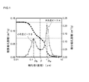
上記目的を実現するべく本発明により、正極集電体および該集電体の表面に正極活物質および導電材を含む正極合材層を有する正極を備えるリチウム二次電池が提供される。本発明に係るリチウム二次電池の上記正極合材層は、水銀ポロシメータで測定される細孔分布曲線において、細孔径0.01μm〜10μmの範囲に大小2つの微分細孔容積のピークを有する。上記大小2つのピークのうち、微分細孔容積の小さい方のピークBの細孔径は、微分細孔容積の大きい方のピークAの細孔径よりも小孔径に構成されていることを特徴とする。 To achieve the above object, the present invention provides a lithium secondary battery including a positive electrode current collector and a positive electrode having a positive electrode mixture layer containing a positive electrode active material and a conductive material on the surface of the current collector. The positive electrode mixture layer of the lithium secondary battery according to the present invention has two large and small differential pore volume peaks in a pore diameter range of 0.01 μm to 10 μm in a pore distribution curve measured with a mercury porosimeter. Among the two large and small peaks, the pore diameter of peak B having the smaller differential pore volume is configured to be smaller than the pore diameter of peak A having the larger differential pore volume. .
なお、本明細書において「リチウム二次電池」とは、電解質イオンとしてリチウムイオンを利用し、正負極間のリチウムイオンの移動により充放電が実現される二次電池をいう。一般にリチウムイオン電池と称される二次電池は、本明細書におけるリチウム二次電池に包含される典型例である。
また、本明細書において「正極活物質」とは、二次電池において電荷担体となる化学種(ここではリチウムイオン)を可逆的に吸蔵および放出(典型的には挿入および脱離)可能な正極側の活物質をいう。In the present specification, the “lithium secondary battery” refers to a secondary battery that uses lithium ions as electrolyte ions and is charged and discharged by movement of lithium ions between the positive and negative electrodes. A secondary battery generally referred to as a lithium ion battery is a typical example included in the lithium secondary battery in this specification.
In this specification, the “positive electrode active material” refers to a positive electrode capable of reversibly occluding and releasing (typically inserting and desorbing) chemical species (here, lithium ions) that serve as charge carriers in a secondary battery. The active material on the side.
本発明者は、ハイレート特性またはサイクル特性に優れたリチウム二次電池における正極では、正極合材層内に多数の細孔が好適な状態で存在することにより、かかる細孔中に非水電解液が含浸(保持)され、良好な導電経路(導電パス)が形成されていることを見出し、本発明を完成するに至った。
すなわち、本発明に係るリチウム二次電池は、正極活物質および導電材を含む正極合材層を有する正極を備えており、水銀ポロシメータで測定される正極合材層の細孔分布曲線において、大小2つの微分細孔容積のピークを有し、当該大小2つのピークのうち、微分細孔容積の小さい方のピークBの細孔径は、微分細孔容積の大きい方の大孔径ピークAよりも小孔径に構成されている。
好ましくは、上記細孔分布曲線において、上記大小2つのピークの間の最小値における細孔径P[μm]が、0.1μm〜0.7μmの間に存在する。
ここで、正極合材層の構成材料の一つである、カーボン粉末等の導電性粉末材料からなる導電材は、嵩高く非常に小さい粒径(典型的には1μm以下、例えば0.001μm〜1μm)を有するのに対し、リチウム遷移金属複合酸化物などが用いられる正極活物質は、導電材の粒径よりも粒径が大きい物質(典型的には1μm〜50μm、好適には2μm〜20μm、例えば3μm〜8μm)が用いられる。そのため、上述の細孔分布曲線において、大孔径ピークAは概ね正極活物質同士の間隙で生じる細孔を示し、小孔径ピークBは概ね導電材同士の間隙で生じる細孔をそれぞれ示すものであることが考えられる。本発明では、このような大孔径ピークAおよび小孔径ピークBからなる細孔が正極合材層に形成されることにより非水電解液の拡散性が向上するため、当該細孔中に含浸(保持)された電解液を介して、リチウムイオンの移動が効率良く行われるようになる。その結果、ハイレート充放電を繰り返す態様で使用されても優れた電池性能(サイクル特性またはハイレート特性)を有するリチウム二次電池を製造することができる。In the positive electrode in a lithium secondary battery excellent in high rate characteristics or cycle characteristics, the present inventor presents a nonaqueous electrolyte solution in the pores because a large number of pores are present in a suitable state in the positive electrode mixture layer. Was found to be impregnated (held) and a good conductive path (conductive path) was formed, and the present invention was completed.
That is, the lithium secondary battery according to the present invention includes a positive electrode having a positive electrode mixture layer containing a positive electrode active material and a conductive material, and the pore distribution curve of the positive electrode mixture layer measured by a mercury porosimeter is large or small. It has two differential pore volume peaks, and of the two large and small peaks, the pore diameter of peak B having the smaller differential pore volume is smaller than that of large pore diameter peak A having the larger differential pore volume. The hole diameter is configured.
Preferably, in the pore distribution curve, the pore diameter P [μm] at the minimum value between the two large and small peaks is between 0.1 μm and 0.7 μm.
Here, the conductive material made of a conductive powder material such as carbon powder, which is one of the constituent materials of the positive electrode mixture layer, is bulky and has a very small particle size (typically 1 μm or less, for example, 0.001 μm to 1 μm), a positive electrode active material using a lithium transition metal composite oxide or the like is a material having a particle size larger than that of the conductive material (typically 1 μm to 50 μm, preferably 2 μm to 20 μm). For example, 3 μm to 8 μm). Therefore, in the pore distribution curve described above, the large pore peak A generally indicates pores generated in the gap between the positive electrode active materials, and the small pore peak B generally indicates pores generated in the gap between the conductive materials. It is possible. In the present invention, since the diffusibility of the non-aqueous electrolyte is improved by forming such a pore having the large pore diameter peak A and the small pore diameter peak B in the positive electrode mixture layer, the pores are impregnated ( The lithium ions are efficiently transferred through the retained electrolyte solution. As a result, it is possible to manufacture a lithium secondary battery having excellent battery performance (cycle characteristics or high rate characteristics) even when used in a mode in which high rate charge / discharge is repeated.
また、本発明によって提供されるリチウム二次電池の一態様では、上記大孔径ピークAの最大値における細孔径Pa[μm]と、上記小孔径ピークBの最大値における細孔径Pb[μm]とが、0.1≦(Pb/Pa)≦0.8を満たしている。
上記細孔分布曲線において示される大小2つのピークの細孔径比(Pb/Pa)が上記範囲を満たすリチウム二次電池では、正極合材層内における非水電解液の拡散性がさらに向上し、当該細孔に好適量の非水電解液が十分に保持されるため、正極合材層の導電性が向上する。その結果、優れた電池性能(サイクル特性またはハイレート特性)を有するリチウム二次電池を製造することができる。In one aspect of the lithium secondary battery provided by the present invention, the pore diameter Pa [μm] at the maximum value of the large pore diameter peak A and the pore diameter Pb [μm] at the maximum value of the small pore diameter peak B are However, 0.1 ≦ (Pb / Pa) ≦ 0.8 is satisfied.
In the lithium secondary battery in which the pore size ratio (Pb / Pa) of the two large and small peaks shown in the pore distribution curve satisfies the above range, the diffusibility of the non-aqueous electrolyte in the positive electrode mixture layer is further improved, Since a suitable amount of the non-aqueous electrolyte is sufficiently retained in the pores, the conductivity of the positive electrode mixture layer is improved. As a result, a lithium secondary battery having excellent battery performance (cycle characteristics or high rate characteristics) can be manufactured.
さらに、本発明によって提供されるリチウム二次電池の好ましい他の一態様では、上記細孔分布曲線において、上記細孔径Pa[μm]は、0.2μm〜1.2μmの間に存在する。
上記細孔分布曲線において示される大小2つのピークのうち、大孔径ピークAは、導電材の粒径(典型的には1μm以下、例えば0.001μm〜1μm)よりも大きい粒径(典型的には1μm〜50μm、好適には2μm〜20μm、例えば3μm〜8μm)からなる正極活物質同士の間隙によって形成された細孔を概ね示している。従って、大孔径ピークAの最大値におけるPa[μm]が上記範囲を満たす細孔を有する正極合材層は、良好な導電性を備え得る。その結果、正極合材層内の細孔中に含浸された電解液を介して、リチウムイオンの移動が効率良く行われるようになり、ハイレート充放電に対しても内部抵抗の上昇が抑制されたリチウム二次電池を提供することができる。Furthermore, in another preferable aspect of the lithium secondary battery provided by the present invention, in the pore distribution curve, the pore diameter Pa [μm] is between 0.2 μm and 1.2 μm.
Of the two large and small peaks shown in the pore distribution curve, the large pore diameter peak A is a particle diameter (typically 1 μm or less, typically 0.001 μm to 1 μm) larger than the particle diameter (typically 0.001 μm to 1 μm). Generally indicates pores formed by gaps between positive electrode active materials composed of 1 μm to 50 μm, preferably 2 μm to 20 μm, for example, 3 μm to 8 μm. Therefore, the positive electrode mixture layer having pores in which Pa [μm] at the maximum value of the large pore diameter peak A satisfies the above range can have good conductivity. As a result, lithium ions are efficiently transferred through the electrolyte solution impregnated in the pores in the positive electrode mixture layer, and an increase in internal resistance is suppressed even for high-rate charge / discharge. A lithium secondary battery can be provided.
また、好ましく提供されるリチウム二次電池の他の一態様では、上記正極合材層に含まれる正極活物質として、平均粒径1μm〜10μmからなるリチウム遷移金属複合酸化物が使用される。 In another aspect of the lithium secondary battery that is preferably provided, a lithium transition metal composite oxide having an average particle diameter of 1 μm to 10 μm is used as the positive electrode active material contained in the positive electrode mixture layer.
さらに、好ましい一態様では、上記正極合材層に含まれる導電材として、アセチレンブラック、ファーネスブラック、ケッチェンブラックおよびグラファイト粉末からなる群より選択される少なくとも1種が使用される。
正極活物質よりも粒径が小さく導電性が良好な上記材料は、正極合材層中において細孔径の小さい間隙(細孔)を好適に形成する。その結果、かかる細孔中に非水電解液が含浸され易く、導電効率の優れたリチウム二次電池を提供し得る。Further, in a preferred embodiment, at least one selected from the group consisting of acetylene black, furnace black, ketjen black and graphite powder is used as the conductive material contained in the positive electrode mixture layer.
The material having a smaller particle size and better conductivity than the positive electrode active material suitably forms gaps (pores) having a small pore diameter in the positive electrode mixture layer. As a result, it is possible to provide a lithium secondary battery that is easy to be impregnated with the non-aqueous electrolyte in the pores and has excellent conductivity efficiency.
また、本発明は、他の側面として、リチウム二次電池を製造する方法を提供する。すなわち、本発明によって提供される製造方法は、正極集電体および該集電体の表面に正極活物質および導電材を含む正極合材層を有する正極を備えるリチウム二次電池の製造方法であって、以下の工程、(1)上記正極集電体の表面に上記正極合材層を形成する工程、(2)上記正極合材層の細孔分布を水銀ポロシメータで測定し、該測定で得られる細孔分布曲線が以下の条件を具備する正極を選択する工程、
(a)細孔径0.01μm〜10μmの範囲に大小2つの微分細孔容積のピークを有すること、
(b)上記大小2つのピークのうち、微分細孔容積の小さい方のピークBの細孔径は、微分細孔容積の大きい方のピークAの細孔径よりも小孔径に構成されていること、
(3)上記選択した正極を用いてリチウム二次電池を構築する工程、を包含することを特徴とする。
かかる製造方法によると、上記大孔径ピークAおよび小孔径ピークBからなる細孔を正極合材層に形成することができる。これにより、当該細孔における非水電解液の拡散性が向上するため、細孔中に含浸(保持)された電解液を介してリチウムイオンの移動が効率良く行われるようになる。その結果、ハイレート充放電を繰り返す態様で使用されても優れた電池性能(サイクル特性またはハイレート特性)を有するリチウム二次電池を製造することができる。
好ましくは、上記測定で得られる細孔分布曲線において、上記大小2つのピークの間の最小値における細孔径P[μm]が、0.1μm〜0.7μmの間に存在する正極を選択する。Moreover, this invention provides the method of manufacturing a lithium secondary battery as another aspect. That is, the manufacturing method provided by the present invention is a method for manufacturing a lithium secondary battery including a positive electrode current collector and a positive electrode having a positive electrode mixture layer containing a positive electrode active material and a conductive material on the surface of the current collector. Then, (1) the step of forming the positive electrode mixture layer on the surface of the positive electrode current collector, (2) the pore distribution of the positive electrode mixture layer is measured with a mercury porosimeter and obtained by the measurement. A step of selecting a positive electrode having a pore distribution curve having the following conditions:
(A) having two large and small differential pore volume peaks in the pore diameter range of 0.01 μm to 10 μm;
(B) Among the two large and small peaks, the pore diameter of peak B having the smaller differential pore volume is configured to be smaller than the pore diameter of peak A having the larger differential pore volume,
(3) A step of constructing a lithium secondary battery using the selected positive electrode is included.
According to this manufacturing method, pores composed of the large pore diameter peak A and the small pore diameter peak B can be formed in the positive electrode mixture layer. Thereby, since the diffusibility of the nonaqueous electrolytic solution in the pores is improved, lithium ions can be efficiently transferred through the electrolytic solution impregnated (held) in the pores. As a result, it is possible to manufacture a lithium secondary battery having excellent battery performance (cycle characteristics or high rate characteristics) even when used in a mode in which high rate charge / discharge is repeated.
Preferably, in the pore distribution curve obtained by the above measurement, a positive electrode having a pore diameter P [μm] at a minimum value between the two large and small peaks between 0.1 μm and 0.7 μm is selected.
また、本発明によって提供される好ましい一態様のリチウム二次電池を製造する方法では、上記測定で得られる細孔分布曲線において、さらに条件として、前記大孔径ピークAの最大値における細孔径Pa[μm]と、前記小孔径ピークBの最大値における細孔径Pb[μm]とが、0.1≦(Pb/Pa)≦0.8を満たしている正極を選択する。
上記細孔分布曲線において示される大小2つのピークの細孔径比(Pb/Pa)が上記範囲を満たすリチウム二次電池では、正極合材層内における非水電解液の拡散性が向上し、当該細孔に好適量の非水電解液が十分に保持されるため、正極合材層の導電性が向上する。その結果、優れた電池性能(サイクル特性またはハイレート特性)を有するリチウム二次電池を製造することができる。Moreover, in the method for producing a lithium secondary battery according to a preferred embodiment provided by the present invention, in the pore distribution curve obtained by the above measurement, the pore diameter Pa [ μm] and a positive electrode having a pore diameter Pb [μm] at the maximum value of the small pore diameter peak B satisfying 0.1 ≦ (Pb / Pa) ≦ 0.8 is selected.
In the lithium secondary battery in which the pore size ratio (Pb / Pa) of the two large and small peaks shown in the pore distribution curve satisfies the above range, the diffusibility of the non-aqueous electrolyte in the positive electrode mixture layer is improved. Since a suitable amount of the non-aqueous electrolyte is sufficiently retained in the pores, the conductivity of the positive electrode mixture layer is improved. As a result, a lithium secondary battery having excellent battery performance (cycle characteristics or high rate characteristics) can be manufactured.
また、本発明によると、ここに開示されるいずれかのリチウム二次電池を備える車両が提供される。本発明によって提供されるリチウム二次電池は、車両に搭載される動力源として適した電池特性(サイクル特性またはハイレート特性)を示すものであり得る。したがって、かかるリチウム二次電池は、ハイブリッド自動車、電気自動車、燃料電池自動車のような電動機を備える自動車等の車両に搭載されるモーター(電動機)用の電源として好適に使用され得る。 Moreover, according to this invention, a vehicle provided with one of the lithium secondary batteries disclosed here is provided. The lithium secondary battery provided by the present invention may exhibit battery characteristics (cycle characteristics or high rate characteristics) suitable as a power source mounted on a vehicle. Therefore, such a lithium secondary battery can be suitably used as a power source for a motor (electric motor) mounted on a vehicle such as an automobile equipped with an electric motor such as a hybrid vehicle, an electric vehicle, and a fuel cell vehicle.
以下、本発明の好適な実施形態を説明する。なお、本明細書において特に言及している事項以外の事柄であって本発明の実施に必要な事柄は、当該分野における従来技術に基づく当業者の設計事項として把握され得る。本発明は、本明細書に開示されている内容と当該分野における技術常識とに基づいて実施することができる。 Hereinafter, preferred embodiments of the present invention will be described. Note that matters other than matters specifically mentioned in the present specification and necessary for the implementation of the present invention can be grasped as design matters of those skilled in the art based on the prior art in this field. The present invention can be carried out based on the contents disclosed in this specification and common technical knowledge in the field.
まず、本実施形態に係るリチウム二次電池の正極の各構成要素について説明する。ここで開示されるリチウム二次電池(典型的にはリチウムイオン電池)は、上述のとおり、正極活物質および導電材を含む正極合材層が正極集電体の表面に形成された正極を備えている。上記正極合材層には、電荷担体となるリチウムイオンを吸蔵および放出可能な粉末状の正極活物質と導電材とを含んでいる。 First, each component of the positive electrode of the lithium secondary battery according to the present embodiment will be described. As described above, the lithium secondary battery (typically a lithium ion battery) disclosed herein includes a positive electrode in which a positive electrode mixture layer including a positive electrode active material and a conductive material is formed on the surface of the positive electrode current collector. ing. The positive electrode mixture layer includes a powdered positive electrode active material capable of inserting and extracting lithium ions serving as charge carriers and a conductive material.
上記正極合材層に含まれる正極活物質としては、本発明の目的を実現し得る限りにおいて従来からリチウム二次電池に用いられる物質の一種または二種以上を特に限定なく使用することができる。典型的な正極活物質として、層状岩塩構造あるいはスピネル構造等を有するリチウム遷移金属複合酸化物が挙げられる。例えば、リチウム(Li)と少なくとも一種の遷移金属元素を含む、リチウムニッケル系複合酸化物、リチウムコバルト系複合酸化物、リチウムマンガン系複合酸化物、リチウムニッケルコバルトマンガン系複合酸化物等が例示される。 As the positive electrode active material contained in the positive electrode mixture layer, one or more kinds of substances conventionally used in lithium secondary batteries can be used without particular limitation as long as the object of the present invention can be realized. A typical positive electrode active material is a lithium transition metal composite oxide having a layered rock salt structure or a spinel structure. For example, lithium nickel based composite oxide, lithium cobalt based composite oxide, lithium manganese based composite oxide, lithium nickel cobalt manganese based composite oxide, etc. containing lithium (Li) and at least one transition metal element are exemplified. .
ここで、リチウムニッケル系複合酸化物とは、リチウム(Li)とニッケル(Ni)とを構成金属元素とする酸化物のほか、LiおよびNi以外に他の少なくとも一種の金属元素(すなわち、LiとNi以外の遷移金属元素および/または典型金属元素)を典型的にはNiよりも少ない割合(原子数換算。LiおよびNi以外の金属元素を二種以上含む場合にはそれらの合計量としてNiよりも少ない割合)で構成金属元素として含む酸化物をも包含する意味である。上記LiおよびNi以外の金属元素は、例えば、カルシウム(Ca),コバルト(Co),アルミニウム(Al),マンガン(Mn),クロム(Cr),鉄(Fe),バナジウム(V),マグネシウム(Mg),チタン(Ti),ジルコニウム(Zr),ニオブ(Nb),モリブデン(Mo),タングステン(W),銅(Cu),亜鉛(Zn),ガリウム(Ga),インジウム(In),スズ(Sn),ランタン(La)およびセリウム(Ce)からなる群から選択される一種または二種以上の金属元素であり得る。リチウムコバルト系複合酸化物およびリチウムマンガン系複合酸化物についても同様の意味である。 Here, the lithium nickel-based composite oxide is an oxide having lithium (Li) and nickel (Ni) as constituent metal elements, and at least one other metal element (that is, Li and Ni) in addition to Li and Ni. A transition metal element other than Ni and / or a typical metal element) is typically less than Ni (in terms of the number of atoms. When two or more metal elements other than Li and Ni are included, the total amount thereof is more than Ni. In a small proportion) includes oxides contained as constituent metal elements. Examples of the metal elements other than Li and Ni include calcium (Ca), cobalt (Co), aluminum (Al), manganese (Mn), chromium (Cr), iron (Fe), vanadium (V), and magnesium (Mg). ), Titanium (Ti), zirconium (Zr), niobium (Nb), molybdenum (Mo), tungsten (W), copper (Cu), zinc (Zn), gallium (Ga), indium (In), tin (Sn) ), Lanthanum (La) and cerium (Ce), or one or more metal elements. The same meaning is applied to the lithium cobalt complex oxide and the lithium manganese complex oxide.
または、リチウム以外の遷移金属元素を複数種含む、ニッケル・マンガン系のLiNixMn1−xO2(0<x<1)やLiNixMn2−xO4(0<x<2)、ニッケル・コバルト系のLiNixCo1−xO2(0<x<1)、コバルト・マンガン系のLiCoxMn1−xO2(0<x<1)で表わされるような、二元系リチウム遷移金属複合酸化物でもよい。あるいは、ニッケル・コバルト・マンガン系のような三元系リチウム遷移金属複合酸化物(典型的にはLiNi1/3Co1/3Mn1/3O2)でもよい。なお、一般式がLiMPO4(MはCo、Ni、Mn、Feのうちの少なくとも一種以上の元素;例えばLiFePO4、LiMnPO4)で表記されるオリビン型リン酸リチウムを正極活物質として用いてもよい。Alternatively, a nickel / manganese-based LiNi x Mn 1-x O 2 (0 <x <1) or LiNi x Mn 2-x O 4 (0 <x <2) containing a plurality of transition metal elements other than lithium, Binary system represented by nickel-cobalt-based LiNi x Co 1-x O 2 (0 <x <1) and cobalt-manganese-based LiCo x Mn 1-x O 2 (0 <x <1) Lithium transition metal composite oxide may be used. Alternatively, a ternary lithium transition metal composite oxide (typically LiNi 1/3 Co 1/3 Mn 1/3 O 2 ) such as nickel, cobalt, and manganese may be used. Note that olivine type lithium phosphate represented by the general formula LiMPO 4 (M is at least one element of Co, Ni, Mn, Fe; for example, LiFePO 4 , LiMnPO 4 ) may be used as the positive electrode active material. Good.
また、上記正極活物質として、タップ密度が凡そ0.5g/cm3〜3g/cm3、好適には概ね1.0g/cm3〜2.0g/cm3であって、平均粒径が典型的には1μm〜50μm、好適には2μm〜20μm、例えば3μm〜8μmを好ましく使用し得る。ここで、「平均粒径」とは、レーザ散乱・回折法に基づく粒度分布測定装置に基づいて測定した粒度分布から導き出せるメジアン径(D50:50%体積平均粒子径)をいう。The positive electrode active material has a tap density of about 0.5 g / cm 3 to 3 g / cm 3 , preferably about 1.0 g / cm 3 to 2.0 g / cm 3 , and an average particle size is typical. Specifically, 1 μm to 50 μm, preferably 2 μm to 20 μm, for example, 3 μm to 8 μm can be preferably used. Here, the “average particle diameter” refers to a median diameter (D50: 50% volume average particle diameter) that can be derived from a particle size distribution measured based on a particle size distribution measuring apparatus based on a laser scattering / diffraction method.
なお、正極活物質として使用し得る上記リチウム遷移金属複合酸化物としては、例えば、従来公知の方法で調製・提供されるリチウム遷移金属複合酸化物粉末をそのまま使用することができる。例えば、原子組成に応じて適宜選択されるいくつかの原料化合物を所定のモル比で混合し、適当な手段で焼成することによって該酸化物を調製することができる。また、焼成物を適当な手段で粉砕、造粒および分級することにより、タップ密度および/または平均粒径を有する粒子によって実質的に構成された粒状のリチウム遷移金属複合酸化物粉末を得ることができる。 In addition, as said lithium transition metal complex oxide which can be used as a positive electrode active material, the lithium transition metal complex oxide powder prepared and provided by a conventionally well-known method can be used as it is, for example. For example, the oxide can be prepared by mixing several raw material compounds appropriately selected according to the atomic composition at a predetermined molar ratio and firing by an appropriate means. In addition, by pulverizing, granulating and classifying the fired product by appropriate means, a granular lithium transition metal composite oxide powder substantially composed of particles having a tap density and / or an average particle diameter can be obtained. it can.
また、上記正極合材層に含まれる導電材としては、カーボン粉末やカーボンファイバー等の導電性粉末材料が好ましく用いられる。カーボン粉末としては、種々のカーボンブラックを使用してよい。例えば、アセチレンブラック、ファーネスブラック、ケッチェンブラックおよびグラファイト粉末からなる群より選択される少なくとも1種を好適に使用し得る。また、炭素繊維、金属繊維などの導電性繊維類などを単独又はこれらの混合物として含ませることができる。なお、これらのうち一種のみを用いても、二種以上を併用してもよい。また、導電材の平均粒径は限定されないが、典型的には1μm以下、例えば0.001μm〜1μmの平均粒径を有する材料をより好ましく使用し得る。 Moreover, as a conductive material contained in the positive electrode mixture layer, a conductive powder material such as carbon powder or carbon fiber is preferably used. Various carbon blacks may be used as the carbon powder. For example, at least one selected from the group consisting of acetylene black, furnace black, ketjen black and graphite powder can be suitably used. In addition, conductive fibers such as carbon fiber and metal fiber can be contained alone or as a mixture thereof. In addition, only 1 type may be used among these, or 2 or more types may be used together. The average particle diameter of the conductive material is not limited, but typically, a material having an average particle diameter of 1 μm or less, for example, 0.001 μm to 1 μm can be used more preferably.
また、ここに開示される上記正極合材層には、結着材等の任意成分を必要に応じて含有し得る。結着材としては、一般的なリチウム二次電池の正極に使用される結着材と同様のもの等を適宜採用することができる。使用する溶媒に溶解または分散可溶なポリマーを選択することが好ましい。
例えば、非水系溶媒を用いる場合においては、ポリフッ化ビニリデン(PVDF)、ポリ塩化ビニリデン(PVDC)等のポリマーを好ましく採用することができる。このような結着材は、一種を単独で用いてもよく、二種以上を組み合わせて用いてもよい。なお、上記で例示したポリマー材料は、結着材としての機能の他に、増粘材その他の添加材としての機能を発揮する目的で使用されることもあり得る。
また、水系溶媒を用いる場合においては、水系溶媒に溶解するポリマーまたは分散するポリマーを使用することができ、水系溶媒に溶解するポリマーとしては、カルボキシメチルセルロース(CMC;典型的にはナトリウム塩)、ヒドロキシエチルセルロース(HEC)、ヒドロキシプロピルセルロース(HPC)、メチルセルロース(MC)、酢酸フタル酸セルロース(CAP)、ヒドロキシプロピルメチルセルロース(HPMC)、ヒドロキシプロピルメチルセルロースフタレート(HPMCP)等のセルロース誘導体、または、ポリビニルアルコール(PVA)等が挙げられる。また、水系溶媒に分散するポリマーとしては、ポリエチレンオキサイド(PEO)、ポリテトラフルオロエチレン(PTFE)、テトラフルオロエチレン−パーフルオロアルキルビニルエーテル共重含体(PFA)、テトラフルオロエチレン−ヘキサフルオロプロピレン共重合体(FEP)、エチレン−テトラフルオロエチレン共重合体(ETFE)等のフッ素系樹脂、酢酸ビニル共重合体、スチレンブタジエンブロック共重合体(SBR)、アクリル酸変性SBR樹脂(SBR系ラテックス)、アラビアゴム等のゴム類が挙げられる。Further, the positive electrode mixture layer disclosed herein may contain an optional component such as a binder as necessary. As the binder, the same binder as that used for the positive electrode of a general lithium secondary battery can be appropriately employed. It is preferable to select a polymer that is soluble or dispersible in the solvent used.
For example, when a non-aqueous solvent is used, a polymer such as polyvinylidene fluoride (PVDF) or polyvinylidene chloride (PVDC) can be preferably used. Such a binder may be used individually by 1 type, and may be used in combination of 2 or more type. In addition, the polymer material illustrated above may be used for the purpose of exhibiting a function as a thickener and other additives in addition to the function as a binder.
In the case of using an aqueous solvent, a polymer that can be dissolved or dispersed in an aqueous solvent can be used. Examples of the polymer that can be dissolved in an aqueous solvent include carboxymethyl cellulose (CMC; typically sodium salt), hydroxy Cellulose derivatives such as ethylcellulose (HEC), hydroxypropylcellulose (HPC), methylcellulose (MC), cellulose acetate phthalate (CAP), hydroxypropylmethylcellulose (HPMC), hydroxypropylmethylcellulose phthalate (HPMCP), or polyvinyl alcohol (PVA) ) And the like. Polymers dispersed in the aqueous solvent include polyethylene oxide (PEO), polytetrafluoroethylene (PTFE), tetrafluoroethylene-perfluoroalkyl vinyl ether copolymer (PFA), tetrafluoroethylene-hexafluoropropylene copolymer. Fluorine resin such as coalescence (FEP), ethylene-tetrafluoroethylene copolymer (ETFE), vinyl acetate copolymer, styrene butadiene block copolymer (SBR), acrylic acid modified SBR resin (SBR latex), Arabic Examples thereof include rubbers such as rubber.
なお、ここで開示されるリチウム二次電池では、上記溶媒として水系溶媒および非水系溶媒のいずれも使用可能である。水系溶媒としては、典型には水であるが、全体として水性を示すものであればよく、すなわち、水または水を主体とする混合溶媒を好ましく用いることができる。該混合溶媒を構成する水以外の溶媒としては、水と均一に混合し得る有機溶剤(低級アルコール、低級ケトン等)の一種または二種以上を適宜選択して用いることができる。例えば、水系溶媒の凡そ80質量%以上(より好ましくは凡そ90質量%以上、さらに好ましくは凡そ95質量%以上)が水である溶媒の使用が好ましい。特に好ましい例として、実質的に水からなる溶媒が挙げられる。また、非水系溶媒の好適例としては、N−メチル−2−ピロリドン(NMP)、メチルエチルケトン、トルエン等が例示される。 Note that in the lithium secondary battery disclosed herein, any of an aqueous solvent and a non-aqueous solvent can be used as the solvent. The aqueous solvent is typically water, but may be any water-based solvent as a whole, that is, water or a mixed solvent mainly composed of water can be preferably used. As the solvent other than water constituting the mixed solvent, one or more organic solvents (lower alcohol, lower ketone, etc.) that can be uniformly mixed with water can be appropriately selected and used. For example, it is preferable to use a solvent in which about 80% by mass or more (more preferably about 90% by mass or more, more preferably about 95% by mass or more) of the aqueous solvent is water. A particularly preferred example is a solvent consisting essentially of water. Further, preferred examples of the non-aqueous solvent include N-methyl-2-pyrrolidone (NMP), methyl ethyl ketone, toluene and the like.
ここで、上記正極合材層を構成する材料のうち、カーボン粉末等の導電性粉末材料からなる導電材は、嵩高く非常に小さい粒径(典型的には1μm以下、例えば0.001μm〜1μm)を有するのに対し、リチウム遷移金属複合酸化物などが用いられる正極活物質は、導電材の粒径よりも大きい粒径(典型的には1μm〜50μm、好適には2μm〜20μm、例えば3μm〜8μm)を有する物質が用いられるため、これらの材料同士の間隙によって正極合材層内に多数の細孔が形成されている。そこで、かかる正極合材層の細孔分布を水銀ポロシメータで測定すると、図1に示されるような細孔分布曲線を有する。 Here, among the materials constituting the positive electrode mixture layer, a conductive material made of a conductive powder material such as carbon powder has a bulky and very small particle size (typically 1 μm or less, for example, 0.001 μm to 1 μm). ), A positive electrode active material in which a lithium transition metal composite oxide or the like is used has a particle size larger than the particle size of the conductive material (typically 1 μm to 50 μm, preferably 2 μm to 20 μm, for example 3 μm). Since a substance having ˜8 μm) is used, a large number of pores are formed in the positive electrode mixture layer by gaps between these materials. Therefore, when the pore distribution of the positive electrode mixture layer is measured with a mercury porosimeter, a pore distribution curve as shown in FIG. 1 is obtained.
図1は、一実施形態に係るリチウム二次電池の正極合材層の細孔分布状態を示す図である。図1における細孔径と微分細孔容積との関係を示す細孔分布曲線(白色プロット)によると、ここで開示されるリチウム二次電池の正極合材層は、細孔径0.01μm〜10μmの範囲に大小2つの微分細孔容積のピークを有する構造を備えている。そして、かかる大小2つのピークの間の最小値における細孔径P[μm]が0.1μm〜0.7μm(概ね0.2μm〜0.7μm、例えば0.2μm〜0.5μm)の間に存在する。 FIG. 1 is a diagram illustrating a pore distribution state of a positive electrode mixture layer of a lithium secondary battery according to an embodiment. According to the pore distribution curve (white plot) showing the relationship between the pore diameter and the differential pore volume in FIG. 1, the positive electrode mixture layer of the lithium secondary battery disclosed here has a pore diameter of 0.01 μm to 10 μm. It has a structure having two large and small differential pore volume peaks in the range. And the pore diameter P [μm] at the minimum value between the two peaks is between 0.1 μm and 0.7 μm (approximately 0.2 μm to 0.7 μm, for example, 0.2 μm to 0.5 μm). To do.
さらに、上記微分細孔容積の小さい方のピークBの細孔径は、上記微分細孔容積の大きい方のピークAの細孔径よりも小孔径に構成されている。すなわち、粒径(典型的には1μm〜50μm、好適には2μm〜20μm、例えば3μm〜8μm)の大きい正極活物質同士の間隙で生じる大きい細孔径を有する細孔と、粒径(典型的には1μm以下、例えば0.001μm〜1μm)の小さい導電材同士の間隙で生じる小さい細孔径を有する細孔がそれぞれ正極合材層に存在することを示唆するものである。このような大孔径と小孔径の2つの細孔径ピークを有する細孔が正極合材層に形成されることにより、当該細孔における非水電解液の拡散性が向上し、細孔中に含浸(保持)された電解液を介してリチウムイオンの移動が効率良く行われるようになる。 Furthermore, the pore diameter of peak B having the smaller differential pore volume is configured to be smaller than the pore diameter of peak A having the larger differential pore volume. That is, pores having a large pore size generated in a gap between large positive electrode active materials having a particle size (typically 1 μm to 50 μm, preferably 2 μm to 20 μm, for example 3 μm to 8 μm), and a particle size (typically Indicates that the positive electrode mixture layer has pores each having a small pore diameter generated in a gap between small conductive materials of 1 μm or less (for example, 0.001 μm to 1 μm). By forming such a pore having two pore diameter peaks, a large pore diameter and a small pore diameter, in the positive electrode mixture layer, the diffusibility of the non-aqueous electrolyte in the pore is improved and the pores are impregnated. The lithium ions are efficiently moved through the (held) electrolytic solution.
また、図1に示されるように、上記大孔径ピークAの最大値における細孔径Pa[μm]と、上記小孔径ピークBの最大値における細孔径Pb[μm]とが、0.1≦(Pb/Pa)≦0.8(より好ましくは0.12≦(Pb/Pa)≦0.78)を満たしている。上記細孔分布曲線において示される大小2つのピークの細孔径比が上記範囲を満たすリチウム二次電池では、正極合材層内の細孔に好適量の非水電解液が十分に保持されるため、正極合材層の液保持力が向上する。その結果、ハイレート充放電を繰り返す態様で使用されても優れた電池性能(サイクル特性またはハイレート特性)を有するリチウム二次電池を提供することができる。 Further, as shown in FIG. 1, the pore diameter Pa [μm] at the maximum value of the large pore diameter peak A and the pore diameter Pb [μm] at the maximum value of the small pore diameter peak B are 0.1 ≦ ( Pb / Pa) ≦ 0.8 (more preferably 0.12 ≦ (Pb / Pa) ≦ 0.78). In a lithium secondary battery in which the pore size ratio of the two large and small peaks shown in the pore distribution curve satisfies the above range, a suitable amount of non-aqueous electrolyte is sufficiently retained in the pores in the positive electrode mixture layer. The liquid holding power of the positive electrode mixture layer is improved. As a result, it is possible to provide a lithium secondary battery having excellent battery performance (cycle characteristics or high rate characteristics) even when used in a mode in which high rate charge / discharge is repeated.
さらに、図1に示される細孔分布曲線において、上記細孔径Pa[μm]は、0.2μm〜1.2μmの間に存在する。上記細孔分布曲線において示される大小2つのピークのうち、大孔径ピークAは、正極活物質同士の間隙によって形成された細孔を概ね示している。従って、大孔径ピークAの最大値におけるPa[μm]が上記範囲を満たす細孔を有する正極合材層は、良好な導電性を備え得る。これにより、当該細孔中に含浸された電解液を介して、リチウムイオンの移動が効率良く行われるようになる。 Further, in the pore distribution curve shown in FIG. 1, the pore diameter Pa [μm] is between 0.2 μm and 1.2 μm. Of the two large and small peaks shown in the pore distribution curve, the large pore diameter peak A generally indicates pores formed by the gaps between the positive electrode active materials. Therefore, the positive electrode mixture layer having pores in which Pa [μm] at the maximum value of the large pore diameter peak A satisfies the above range can have good conductivity. Accordingly, lithium ions can be efficiently transferred through the electrolytic solution impregnated in the pores.
ここで、上記正極合材層における細孔分布は、以下のようにして測定することができる。正極集電体の表面に正極合材層が形成された正極を所定面積に切り分けて試料片を用意し、市販される水銀ポロシメータを用いて圧力範囲約4psi〜60000psiの出力で試料片の細孔分布を測定する。これにより、細孔径と細孔容積との関係を示す細孔分布曲線(典型的には、上記圧力範囲において50μm〜0.003μmの範囲内の細孔分布曲線)が得られ、正極合材層に形成された細孔分布状態が確認される。但し、5μm以上は試料片間の隙間と考えられる。 Here, the pore distribution in the positive electrode mixture layer can be measured as follows. A positive electrode having a positive electrode mixture layer formed on the surface of the positive electrode current collector is cut into a predetermined area, and a sample piece is prepared. Using a commercially available mercury porosimeter, the pores of the sample piece are output in a pressure range of about 4 psi to 60000 psi. Measure the distribution. As a result, a pore distribution curve showing the relationship between the pore diameter and the pore volume (typically, a pore distribution curve in the range of 50 μm to 0.003 μm in the pressure range) is obtained, and the positive electrode mixture layer The pore distribution state formed in is confirmed. However, 5 μm or more is considered as a gap between the sample pieces.
なお、上記正極の基材となる正極集電体としては、導電性の良好な金属からなる導電性部材が好ましく用いられる。例えば、アルミニウムまたはアルミニウムを主成分とする合金を用いることができる。正極集電体の形状は、リチウム二次電池の形状等に応じて異なり得るため、特に制限はなく、棒状、板状、シート状、箔状、メッシュ状等の種々の形態であり得る。 In addition, as a positive electrode electrical power collector used as the said base material of a positive electrode, the electroconductive member which consists of metal with favorable electroconductivity is used preferably. For example, aluminum or an alloy containing aluminum as a main component can be used. The shape of the positive electrode current collector can vary depending on the shape of the lithium secondary battery, and is not particularly limited, and may be various forms such as a rod shape, a plate shape, a sheet shape, a foil shape, and a mesh shape.
次いで、本発明に係るリチウム二次電池の製造方法の好ましい態様の一例として正極の製造方法について説明する。
ここに開示される製造方法は、正極活物質および導電材を含む正極合材層が正極集電体の表面に形成された正極を備えるリチウム二次電池を製造する方法であって、本発明の目的を実現し得る限りにおいて、従来から用いられる正極の製造方法と同様の技法を適宜採用することができる。具体的には以下の工程、(1)上記正極集電体の表面に上記正極合材層を形成する工程、(2)上記正極合材層の細孔分布を水銀ポロシメータで測定し、該測定で得られる細孔分布曲線が以下の条件を具備する正極を選択する工程、
(a)細孔径0.01μm〜10μmの範囲に大小2つの微分細孔容積のピークを有すること、
(b)上記大小2つのピークのうち、微分細孔容積の小さい方のピークBの細孔径は、微分細孔容積の大きい方のピークAの細孔径よりも小孔径に構成されていること、
(3)上記選択した正極を用いてリチウム二次電池を構築する工程、を包含する。Next, a method for producing a positive electrode will be described as an example of a preferred embodiment of the method for producing a lithium secondary battery according to the present invention.
The manufacturing method disclosed herein is a method of manufacturing a lithium secondary battery including a positive electrode in which a positive electrode mixture layer including a positive electrode active material and a conductive material is formed on the surface of a positive electrode current collector, As long as the object can be realized, a technique similar to a conventionally used method for manufacturing a positive electrode can be appropriately employed. Specifically, (1) the step of forming the positive electrode mixture layer on the surface of the positive electrode current collector, (2) the pore distribution of the positive electrode mixture layer is measured with a mercury porosimeter, and the measurement is performed. A step of selecting a positive electrode having a pore distribution curve obtained under the following conditions:
(A) having two large and small differential pore volume peaks in the pore diameter range of 0.01 μm to 10 μm;
(B) Among the two large and small peaks, the pore diameter of peak B having the smaller differential pore volume is configured to be smaller than the pore diameter of peak A having the larger differential pore volume,
(3) including a step of constructing a lithium secondary battery using the selected positive electrode.
まず、正極活物質、導電材および結着材等の正極合材層を形成するための材料を適当な溶媒(水系溶媒または非水系溶媒)に添加して混練し、ペーストまたはスラリー状の正極合材層形成用組成物を調製する。なお、正極活物質としては、特に限定されるものではないが、タップ密度が凡そ0.5g/cm3〜3g/cm3、好適には概ね1.0g/cm3〜2.0g/cm3であって、平均粒径が典型的には1μm〜50μm、好ましくは2μm〜20μm、例えば3μm〜8μmを好ましく使用し得る。First, a material for forming a positive electrode mixture layer such as a positive electrode active material, a conductive material, and a binder is added to an appropriate solvent (aqueous solvent or non-aqueous solvent) and kneaded to form a paste or slurry-like positive electrode composite. A material layer forming composition is prepared. The positive electrode active material is not particularly limited, but the tap density is about 0.5 g / cm 3 to 3 g / cm 3 , preferably about 1.0 g / cm 3 to 2.0 g / cm 3. The average particle diameter is typically 1 to 50 μm, preferably 2 to 20 μm, for example 3 to 8 μm.
次いで、正極集電体の表面に上記組成物の塗布量が12mg/cm2〜20mg/cm2になるように塗布した。そして、溶媒を揮発させて乾燥させた後、圧縮(プレス)することにより正極合材層の層密度が、1.0g/cm3〜3.0g/cm3、好適には概ね1.5g/cm3〜2.8g/cm3の範囲になるようにプレスを行い、リチウム二次電池用の正極を製造した。Then, the coating amount of the composition was coated such that the 12mg / cm 2 ~20mg / cm 2 on the surface of the positive electrode current collector. Then, after the solvent is volatilized and dried, the positive electrode mixture layer has a layer density of 1.0 g / cm 3 to 3.0 g / cm 3 , preferably about 1.5 g / cm by compression (pressing). Pressing was performed so as to be in the range of cm 3 to 2.8 g / cm 3 to produce a positive electrode for a lithium secondary battery.
なお、正極集電体に上記組成物を塗布する方法としては、従来公知の方法と同様の技法を適宜採用することができる。例えば、スリットコーター、ダイコーター、グラビアコーター、コンマコーター等の適当な塗布装置を使用することにより、正極集電体に該ペーストを好適に塗布することができる。また、溶媒を乾燥するにあたっては、自然乾燥、熱風、低湿風、真空、赤外線、遠赤外線、および電子線を、単独または組合せにて用いることにより良好に乾燥し得る。さらに、圧縮方法としては、従来公知のロールプレス法、平板プレス法等の圧縮方法を採用することができる。かかる厚さを調整するにあたり、膜厚測定器で該厚みを測定し、プレス圧を調整して所望の厚さになるまで複数回圧縮してもよい。 In addition, as a method of apply | coating the said composition to a positive electrode electrical power collector, the technique similar to a conventionally well-known method is employable suitably. For example, the paste can be suitably applied to the positive electrode current collector by using an appropriate application device such as a slit coater, a die coater, a gravure coater, or a comma coater. Moreover, when drying a solvent, it can dry favorably by using natural drying, a hot air, low-humidity air, a vacuum, infrared rays, far-infrared rays, and an electron beam individually or in combination. Furthermore, as a compression method, a conventionally known compression method such as a roll press method or a flat plate press method can be employed. In adjusting the thickness, the thickness may be measured with a film thickness measuring instrument, and the press pressure may be adjusted to compress a plurality of times until a desired thickness is obtained.
こうして正極合材層を形成した後に、正極を所定面積に切り分けて正極合材層の細孔分布を水銀ポロシメータで測定し、該測定で得られる細孔分布曲線が以下の条件を具備する正極を選択する。かかる条件とは、(a)細孔径0.01μm〜10μmの範囲に大小2つの微分細孔容積のピークを有すること、(b)上記大小2つのピークのうち、微分細孔容積の小さい方のピークBの細孔径は、微分細孔容積の大きい方のピークAの細孔径よりも小孔径に構成されていること、である。さらに好ましくは、上記測定で得られる細孔分布曲線において、上記大孔径ピークAの最大値における細孔径Pa[μm]と、前記小孔径ピークBの最大値における細孔径Pb[μm]とが、0.1≦(Pb/Pa)≦0.8(より好ましくは0.12≦(Pb/Pa)≦0.78)を満たしている正極を選択する。 After forming the positive electrode mixture layer in this manner, the positive electrode is cut into a predetermined area, the pore distribution of the positive electrode mixture layer is measured with a mercury porosimeter, and the pore distribution curve obtained by the measurement has a positive electrode having the following conditions: select. Such conditions include (a) having two large and small differential pore volume peaks in the pore diameter range of 0.01 μm to 10 μm, and (b) of the two large and small peaks having the smaller differential pore volume. The peak B has a smaller pore size than the peak A having a larger differential pore volume. More preferably, in the pore distribution curve obtained by the above measurement, the pore diameter Pa [μm] at the maximum value of the large pore diameter peak A and the pore diameter Pb [μm] at the maximum value of the small pore diameter peak B are: A positive electrode satisfying 0.1 ≦ (Pb / Pa) ≦ 0.8 (more preferably 0.12 ≦ (Pb / Pa) ≦ 0.78) is selected.
上記大孔径ピークAおよび小孔径ピークBからなる細孔を正極合材層に有する正極は、当該細孔における非水電解液の拡散性が向上するため、細孔中に含浸(保持)された電解液を介してリチウムイオンの移動が効率良く行われるようになる。従って、上記選択した正極を用いてリチウム二次電池を構築することにより、ハイレート充放電を繰り返す態様で使用されても優れた電池性能(サイクル特性またはハイレート特性)を有するリチウム二次電池を提供することができる。 The positive electrode having the pores composed of the large pore diameter peak A and the small pore diameter peak B in the positive electrode mixture layer is impregnated (held) in the pores in order to improve the diffusibility of the nonaqueous electrolytic solution in the pores. Lithium ions can be efficiently transferred through the electrolytic solution. Therefore, by constructing a lithium secondary battery using the selected positive electrode, a lithium secondary battery having excellent battery performance (cycle characteristics or high rate characteristics) even when used in a mode in which high rate charge / discharge is repeated is provided. be able to.
次に、ここで開示されるリチウム二次電池の負極の各構成要素について説明する。かかる負極は、負極集電体の表面に負極合材層が形成された構成を備える。上記負極の基材となる負極集電体としては、導電性の良好な金属からなる導電性部材が好ましく用いられる。例えば、銅、または銅を主成分とする合金を用いることができる。負極集電体の形状は、リチウム二次電池の形状等に応じて異なり得るため特に制限はなく、棒状、板状、シート状、箔状、メッシュ状等の種々の形態であり得る。車両搭載用高出力電源として用いられるリチウム二次電池の負極の集電体としては、厚さが5〜100μm程度の銅箔が好適に用いられる。 Next, each component of the negative electrode of the lithium secondary battery disclosed here will be described. Such a negative electrode has a configuration in which a negative electrode mixture layer is formed on the surface of a negative electrode current collector. As the negative electrode current collector serving as the base material of the negative electrode, a conductive member made of a highly conductive metal is preferably used. For example, copper or an alloy containing copper as a main component can be used. The shape of the negative electrode current collector may vary depending on the shape of the lithium secondary battery and the like, and thus is not particularly limited, and may be various forms such as a rod shape, a plate shape, a sheet shape, a foil shape, and a mesh shape. A copper foil having a thickness of about 5 to 100 μm is suitably used as a negative electrode current collector of a lithium secondary battery used as a high-output power source for mounting on a vehicle.
上記負極集電体の表面に形成された負極合材層には、電荷担体となるリチウムイオンを吸蔵および放出可能な負極活物質が含まれる。負極活物質としては、従来からリチウム二次電池に用いられる物質の一種または二種以上を特に限定なく使用することができる。例えば、カーボン粒子が挙げられる。少なくとも一部にグラファイト構造(層状構造)を含む粒子状の炭素材料(カーボン粒子)が好ましく用いられる。いわゆる黒鉛質のもの(グラファイト)、難黒鉛化炭素質のもの(ハードカーボン)、易黒鉛化炭素質のもの(ソフトカーボン)、これらを組み合わせた構造を有するもののいずれの炭素材料も好適に使用され得る。中でも特に、黒鉛粒子を好ましく使用することができる。黒鉛粒子(例えばグラファイト)は、電荷担体としてのリチウムイオンを好適に吸蔵することができるため導電性に優れる。また、粒径が小さく単位体積当たりの表面積が大きいことからよりハイレート充放電に適した負極活物質となり得る。 The negative electrode mixture layer formed on the surface of the negative electrode current collector contains a negative electrode active material capable of inserting and extracting lithium ions serving as charge carriers. As the negative electrode active material, one type or two or more types of materials conventionally used in lithium secondary batteries can be used without any particular limitation. An example is carbon particles. A particulate carbon material (carbon particles) containing a graphite structure (layered structure) at least partially is preferably used. Any carbon material of a so-called graphitic material (graphite), non-graphitizable carbon material (hard carbon), easily graphitized carbon material (soft carbon), or a combination of these materials is preferably used. obtain. Among these, graphite particles can be preferably used. Graphite particles (eg, graphite) are excellent in conductivity because they can suitably occlude lithium ions as charge carriers. Further, since the particle size is small and the surface area per unit volume is large, it can be a negative electrode active material more suitable for high-rate charge / discharge.
また、上記負極合材層は、典型的には、その構成成分として、上記負極活物質の他に、結着材等の任意成分を必要に応じて含有し得る。かかる結着材としては、一般的なリチウム二次電池の負極に使用される結着材と同様のものを適宜採用することができ、上述の正極の構成要素で列挙した結着材として機能し得る各種のポリマー材料を好適に使用し得る。 Moreover, the said negative electrode compound material layer can typically contain arbitrary components, such as a binder, as needed in addition to the said negative electrode active material as the structural component. As such a binder, the same binder as that used for the negative electrode of a general lithium secondary battery can be adopted as appropriate, and functions as the binder listed in the components of the positive electrode described above. The various polymer materials obtained can be suitably used.
次いで、上記リチウム二次電池の負極の製造方法について説明する。上記負極集電体の表面に負極合材層を形成するため、まず、負極活物質を、結着材等と共に適当な溶媒(水系溶媒または非水系溶媒)で混合して、ペーストまたはスラリー状の負極合材層形成用組成物を調製する。 Subsequently, the manufacturing method of the negative electrode of the said lithium secondary battery is demonstrated. In order to form the negative electrode mixture layer on the surface of the negative electrode current collector, first, the negative electrode active material is mixed with a binder or the like with an appropriate solvent (aqueous solvent or non-aqueous solvent) to obtain a paste or slurry A composition for forming a negative electrode mixture layer is prepared.
なお、各構成材料の配合比率は、例えば、負極合材層に占める負極活物質の割合が、凡そ50質量%以上であることが好ましく、凡そ85〜99質量%(例えば90〜97質量%)であることがより好ましい。また、負極合材層に占める結着材の割合を例えば凡そ1〜15質量%とすることができ、通常は凡そ3〜10質量%とすることが好ましい。こうして調製した組成物を負極集電体に塗布し、溶媒を揮発させて乾燥させた後、圧縮(プレス)する。これにより該ペーストを用いて形成された負極合材層を負極集電体上に有するリチウム二次電池の負極が得られる。なお、塗布、乾燥および圧縮方法は、上述の正極の製造方法と同様に従来公知の手段を用いることができる。 In addition, as for the blending ratio of each constituent material, for example, the ratio of the negative electrode active material in the negative electrode mixture layer is preferably about 50% by mass or more, and about 85 to 99% by mass (for example, 90 to 97% by mass). It is more preferable that Further, the ratio of the binder in the negative electrode mixture layer can be, for example, about 1 to 15% by mass, and usually about 3 to 10% by mass is preferable. The composition prepared in this manner is applied to a negative electrode current collector, the solvent is evaporated and dried, and then compressed (pressed). Thereby, the negative electrode of the lithium secondary battery which has the negative electrode compound material layer formed using this paste on a negative electrode collector is obtained. In addition, the application | coating, drying, and the compression method can use a conventionally well-known means similarly to the manufacturing method of the above-mentioned positive electrode.
以下、ここに開示される正極を用いて構築される角型形状のリチウム二次電池(リチウムイオン電池)を例にして詳細に説明するが、本発明をかかる実施形態に限定することを意図したものではない。また、本明細書において特に言及している事項以外の事柄であって本発明の実施に必要な事柄(例えば、電極体の構成および製造方法、セパレータの構成および製造方法、リチウム二次電池その他の電池の構築に係る一般的技術等)は、当該分野における従来技術に基づく当業者の設計事項として把握され得る。
なお、以下の図面において、同じ作用を奏する部材・部位には同じ符号を付し、重複する説明は省略又は簡略化することがある。また、各図における寸法関係(長さ、幅、厚さ等)は実際の寸法関係を反映するものではない。Hereinafter, a square-shaped lithium secondary battery (lithium ion battery) constructed using the positive electrode disclosed herein will be described in detail as an example, but the present invention is intended to be limited to such an embodiment. It is not a thing. Further, matters other than the matters specifically mentioned in the present specification and matters necessary for carrying out the present invention (for example, the configuration and manufacturing method of the electrode body, the configuration and manufacturing method of the separator, the lithium secondary battery, etc. General techniques related to battery construction, etc.) can be grasped as design matters of those skilled in the art based on conventional techniques in the field.
In addition, in the following drawings, the same code | symbol is attached | subjected to the member and site | part which show | plays the same effect | action, and the overlapping description may be abbreviate | omitted or simplified. In addition, the dimensional relationships (length, width, thickness, etc.) in each drawing do not reflect actual dimensional relationships.
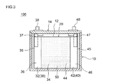
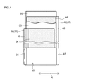
図2は、一実施形態に係る角型形状のリチウム二次電池を模式的に示す斜視図であり、図3は、図2中のIII−III線断面図である。また、図4は、電極体を捲回して作製する状態を模式的に示す斜視図である。
図2および図3に示されるように、本実施形態に係るリチウム二次電池100は、直方体形状の角型の電池ケース10と、該ケース10の開口部12を塞ぐ蓋体14とを備える。この開口部12より電池ケース10内部に扁平形状の電極体(捲回電極体20)及び電解質を収容することができる。また、蓋体14には、外部接続用の正極端子38と負極端子48とが設けられており、それら端子38,48の一部は蓋体14の表面側に突出している。また、外部端子38,48の一部はケース内部で内部正極端子37または内部負極端子47にそれぞれ接続されている。2 is a perspective view schematically showing a rectangular lithium secondary battery according to an embodiment, and FIG. 3 is a cross-sectional view taken along line III-III in FIG. FIG. 4 is a perspective view schematically showing a state in which the electrode body is wound and manufactured.
As shown in FIGS. 2 and 3, the lithium
次に、図3および図4を参照し、本実施形態に係る捲回電極体20について説明する。図4に示されるように、捲回電極体20は、長尺状の正極集電体32の表面に正極合材層34を有するシート状の正極シート30、長尺シート状のセパレータ50、長尺状の負極集電体42の表面に負極合材層44を有するシート状の負極シート40とから構成される。そして、捲回軸方向Rの方向での断面視において、正極シート30及び負極シート40は、2枚のセパレータ50を介して積層されており、正極シート30、セパレータ50、負極シート40、セパレータ50の順に積層されている。該積層物は、軸芯(図示しない)の周囲に筒状に捲回され、得られた捲回電極体20を側面方向から押しつぶして拉げさせることによって扁平形状に成形されている。
Next, the
また、図3に示されるように、本実施形態に係る捲回電極体20は、その捲回軸方向Rの中心部には、正極集電体32の表面上に形成された正極合材層34と、負極集電体42の表面上に形成された負極合材層44とが重なり合って密に積層された部分が形成されている。また、捲回軸方向Rに沿う方向での断面視において、該方向Rの一方の端部において、正極合材層34が形成されずに正極集電体32の露出した部分(正極合材層非形成部36)がセパレータ50および負極シート40(あるいは、正極合材層34と負極合材層44との密な積層部分)からはみ出た状態で積層されて構成されている。即ち、上記電極体20の端部には、正極集電体32における正極合材層非形成部36が積層されて成る正極集電体積層部35が形成されている。また、電極体20の他方の端部も正極シート30と同様の構成であり、負極集電体42における負極合材層非形成部46が積層されて、負極集電体積層部45が形成されている。なお、セパレータ50は、ここでは正極合材層34および負極合材層44の積層部分の幅より大きく、該電極体20の幅より小さい幅を備えるセパレータが用いられ、正極集電体32と負極集電体42が互いに接触して内部短絡を生じさせないように正極合材層34および負極合材層44の積層部分に挟まれるように配されている。
Further, as shown in FIG. 3, the
セパレータ50は、正極シート30および負極シート40の間に介在するシートであって、正極シート30の正極合材層34と、負極シート40の負極合材層44にそれぞれ接するように配置される。そして、正極シート30と負極シート40における両合材層34,44の接触に伴う短絡防止や、該セパレータ50の空孔内に電解質(非水電解液)を含浸させることにより電極間の伝導パス(導電経路)を形成する役割を担っている。
かかるセパレータ50の構成材料としては、樹脂からなる多孔性シート(微多孔質樹脂シート)を好ましく用いることができる。ポリプロピレン、ポリエチレン、ポリスチレン等の多孔質ポリオレフィン系樹脂が特に好ましい。The
As a constituent material of the
本実施形態に係るリチウム二次電池は、以下のように構築することができる。上述した態様で正極(典型的には正極シート30)及び負極(典型的には負極シート40)を2枚のセパレータ50と共に積重ね合わせて捲回し、得られた捲回電極体20を側面方向から押しつぶして拉げさせることによって扁平形状に成形する。そして、正極集電体32の正極合材層非形成部36に内部正極端子37を、負極集電体42の負極合材層非形成部46には内部負極端子47をそれぞれ超音波溶接、抵抗溶接等により接合し、上記扁平形状に形成された捲回電極体20の正極シート30または負極シート40と電気的に接続する。こうして得られた捲回電極体20を電池ケース10に収容した後、非水電解液を注入し、注入口を封止することによって、本実施形態のリチウム二次電池100を構築することができる。なお、電池ケース10の構造、大きさ、材料(例えば金属製またはラミネートフィルム製であり得る)、および正負極を主構成要素とする電極体の構造(例えば捲回構造や積層構造)等について特に制限はない。
The lithium secondary battery according to the present embodiment can be constructed as follows. In the above-described embodiment, the positive electrode (typically positive electrode sheet 30) and the negative electrode (typically negative electrode sheet 40) are stacked and wound together with two
なお、非水電解液は、従来からリチウム二次電池に用いられる非水電解液と同様のものを特に限定なく使用することができる。かかる非水電解液は、典型的には、適当な非水溶媒に支持塩を含有させた組成を有する。上記非水溶媒としては、例えば、プロピレンカーボネート(PC)、エチレンカーボネート(EC)、ジエチルカーボネート(DEC)、ジメチルカーボネート(DMC)、エチルメチルカーボネート(EMC)等からなる群から選択された一種又は二種以上を用いることができる。また、上記支持塩としては、例えば、LiPF6、LiBF4、LiClO4、LiAsF6、LiCF3SO3、LiC4F9SO3、LiN(CF3SO2)2、LiC(CF3SO2)3、LiI等のリチウム化合物(リチウム塩)を用いることができる。なお、非水電解液における支持塩の濃度は、従来のリチウム二次電池で使用される非水電解液と同様でよく、特に制限はない。適当なリチウム化合物(支持塩)を0.5〜1.5mol/L程度の濃度で含有させた電解質を使用することができる。In addition, the nonaqueous electrolyte can use the same thing as the nonaqueous electrolyte conventionally used for a lithium secondary battery without limitation. Such a nonaqueous electrolytic solution typically has a composition in which a supporting salt is contained in a suitable nonaqueous solvent. Examples of the non-aqueous solvent include one or two selected from the group consisting of propylene carbonate (PC), ethylene carbonate (EC), diethyl carbonate (DEC), dimethyl carbonate (DMC), ethyl methyl carbonate (EMC), and the like. More than seeds can be used. Examples of the supporting salt include LiPF 6 , LiBF 4 , LiClO 4 , LiAsF 6 , LiCF 3 SO 3 , LiC 4 F 9 SO 3 , LiN (CF 3 SO 2 ) 2 , LiC (CF 3 SO 2 ). 3. Lithium compounds (lithium salts) such as LiI can be used. In addition, the density | concentration of the support salt in a nonaqueous electrolyte solution may be the same as that of the nonaqueous electrolyte solution used with the conventional lithium secondary battery, and there is no restriction | limiting in particular. An electrolyte containing an appropriate lithium compound (supporting salt) at a concentration of about 0.5 to 1.5 mol / L can be used.
このようにして構築されたリチウム二次電池100は、上述したように、車両搭載用高出力電源として優れた電池特性(ハイレート特性またはサイクル特性)を示すものであり得る。従って、本発明に係るリチウム二次電池100は、特に自動車等の車両に搭載されるモーター(電動機)用電源として好適に使用し得る。従って、図5に模式的に示すように、かかるリチウム二次電池100(当該リチウム二次電池100を複数個直列に接続して形成される組電池の形態であり得る。)を電源として備える車両(典型的には自動車、特にハイブリッド自動車、電気自動車、燃料電池自動車のような電動機を備える自動車)1を提供する。
As described above, the lithium
以下、本発明に関する試験例につき説明するが、本発明をかかる具体例に示すものに限定することを意図したものではない。 Hereinafter, although the test example regarding this invention is demonstrated, it is not intending to limit this invention to what is shown to this specific example.
[試験用リチウム二次電池の正極の作製]
試験用リチウム二次電池の正極を作製した。まず、正極における正極合材層を形成するにあたり、正極活物質としての平均粒径が3μm〜7μm、タップ密度が凡そ1.0g/cm3〜2.0g/cm3のLi1.0Ni0.34Co0.33Mn0.33O2と、結着材としてのポリフッ化ビニリデン(PVDF)と、導電材としてのアセチレンブラックとを、これら材料の質量%比が様々な値をとり得るようにN−メチル−2−ピロリドン(NMP)を加えて混合し、ペースト状の正極合材層形成用組成物を調製した。
そして、正極集電体としての厚み約15μmのアルミニウム箔の両面に上記ペースト状組成物を塗布量が12mg/cm2〜20mg/cm2になるように塗布した。塗布後、乾燥させてローラプレス機にてプレスを行い、層密度が凡そ1.5〜2.8g/cm3となるように正極合材層を形成し、計15通りの正極シートを作製した。[Preparation of positive electrode for test lithium secondary battery]
A positive electrode of a test lithium secondary battery was produced. First, in forming a positive-electrode mixture layer of the positive electrode, Li 1.0 Ni 0 of the average particle diameter of the positive electrode active material ranges from 3 m to 7 m, a tap density of about 1.0g / cm 3 ~2.0g / cm 3 .34 Co 0.33 Mn 0.33 O 2 , polyvinylidene fluoride (PVDF) as a binder, and acetylene black as a conductive material so that the mass% ratio of these materials can take various values. N-methyl-2-pyrrolidone (NMP) was added and mixed to prepare a paste-like composition for forming a positive electrode mixture layer.
The coating amount of the paste composition to both sides of an aluminum foil having a thickness of about 15μm as the positive electrode current collector was coated so as to 12mg / cm 2 ~20mg / cm 2 . After coating, the film was dried and pressed with a roller press to form a positive electrode mixture layer so that the layer density was approximately 1.5 to 2.8 g / cm 3, and a total of 15 positive electrode sheets were prepared. .
<細孔分布測定>
上記作製した各正極シートを約2cm×1cm角に切り分けて試料片を調製し、正極合材層内の細孔分布を測定した。試料片重量は凡そ0.5g、ステム使用率10〜25%とした。測定には、水銀ポロシメータ(株式会社島津製作所製「オートポアIII9410」)を用いた。上記試料片をセルに入れ、圧力4psi〜60000psiで、正極合材層内の細孔分布を測定した。そして、細孔径0.01μm〜10μmの範囲の細孔分布曲線から、上述のとおり、大孔径ピークAの最大値における細孔径Pa[μm]と、上記小孔径ピークBの最大値における細孔径Pb[μm]との細孔径比(Pb/Pa)を算出した(図1参照)。<Measurement of pore distribution>
Each of the prepared positive electrode sheets was cut into approximately 2 cm × 1 cm squares to prepare sample pieces, and the pore distribution in the positive electrode mixture layer was measured. The weight of the sample piece was about 0.5 g and the stem usage rate was 10 to 25%. For the measurement, a mercury porosimeter (“Autopore III 9410” manufactured by Shimadzu Corporation) was used. The sample piece was placed in a cell, and the pore distribution in the positive electrode mixture layer was measured at a pressure of 4 psi to 60000 psi. From the pore distribution curve in the range of 0.01 μm to 10 μm, the pore diameter Pa [μm] at the maximum value of the large pore diameter peak A and the pore diameter Pb at the maximum value of the small pore diameter peak B as described above. The pore diameter ratio (Pb / Pa) with [μm] was calculated (see FIG. 1).
[試験用リチウム二次電池の負極の作製]
次に、試験用リチウム二次電池の負極を作製した。まず、負極における負極合材層を形成するにあたり、負極活物質としての黒鉛と、結着材としてのスチレンブタジエンブロック共重合体(SBR)と、カルボキシメチルセルロース(CMC)とを、これら材料の質量%比が98:1:1となるようにイオン交換水を加えて混合し、ペースト状の負極活物質層形成用組成物を調製した。
そして、負極集電体としての厚み約10μmの銅箔に単位面積あたりの塗布量が6.4〜11mg/cm2になるように上記ペースト状組成物を負極集電体の両面に塗布した。塗布後、乾燥させてローラプレス機にてプレスを行い、負極シートを作製した。[Preparation of negative electrode for test lithium secondary battery]
Next, a negative electrode of a test lithium secondary battery was produced. First, in forming the negative electrode mixture layer in the negative electrode, graphite as a negative electrode active material, styrene butadiene block copolymer (SBR) as a binder, and carboxymethyl cellulose (CMC) are mass% of these materials. Ion exchange water was added and mixed so that the ratio was 98: 1: 1 to prepare a paste-like composition for forming a negative electrode active material layer.
And the said paste-form composition was apply | coated on both surfaces of the negative electrode collector so that the application quantity per unit area might be 6.4-11 mg / cm < 2 > on the copper foil of thickness about 10 micrometers as a negative electrode collector. After the application, it was dried and pressed with a roller press to produce a negative electrode sheet.
[試験用リチウム二次電池の構築]
上記作製した各正極シートと負極シートとを用いて試験用リチウム二次電池を構築した。すなわち、正極シート及び負極シートを2枚のセパレータとともに積層し、この積層シートを捲回して捲回電極体を作製した。そして、この電極体を電解質とともに容器に収容して、18650型電池(径18mm、高さ65mm)を構築した。非水電解液としては、エチレンカーボネート(EC)とジメチルカーボネート(DMC)とエチルメチルカーボネート(EMC)との3:4:3(体積比)混合溶媒に1mol/LのLiPF6を溶解させた組成を用いた。[Construction of test lithium secondary battery]
A test lithium secondary battery was constructed using each of the prepared positive electrode sheet and negative electrode sheet. That is, a positive electrode sheet and a negative electrode sheet were laminated together with two separators, and this laminated sheet was wound to produce a wound electrode body. And this electrode body was accommodated in the container with electrolyte, and the 18650 type battery (diameter 18mm, height 65mm) was constructed | assembled. As the non-aqueous electrolyte, 1 mol / L LiPF 6 was dissolved in a 3: 4: 3 (volume ratio) mixed solvent of ethylene carbonate (EC), dimethyl carbonate (DMC), and ethyl methyl carbonate (EMC). Was used.
<ハイレートサイクル特性評価>
上記構築した各電池をSOC(State of Charge)60%に調整し、−15℃の温度下にて20Cの定電流で放電させ、その10秒後電圧降下から初期IV抵抗を求めた。<High rate cycle characteristics evaluation>
Each battery constructed as described above was adjusted to SOC (State of Charge) 60%, discharged at a constant current of 20 C at a temperature of −15 ° C., and 10 seconds later, the initial IV resistance was determined from the voltage drop.
次に、各電池を再びSOC60%に調整し、−15℃において、以下の(1)〜(4)からなる充放電サイクルを2500回繰り返すハイレートサイクル試験を行った。その間、100サイクル毎に、SOCを60%に調整する操作を行った。
(1)20Cの定電流で10秒間放電させる。
(2)5秒間休止する。
(3)1Cの定電流で200秒間充電する。
(4)145秒間休止する。Next, each battery was adjusted to SOC 60% again, and a high rate cycle test was performed by repeating the charge / discharge cycle consisting of the following (1) to (4) 2500 times at −15 ° C. Meanwhile, an operation of adjusting the SOC to 60% was performed every 100 cycles.
(1) Discharge at a constant current of 20 C for 10 seconds.
(2) Pause for 5 seconds.
(3) Charge with a constant current of 1 C for 200 seconds.
(4) Pause for 145 seconds.
上記ハイレートサイクル試験後の各電池につき、初期IV抵抗の測定と同様にして、ハイレートサイクル後IV抵抗を測定した。そして、ハイレートサイクル後のIV抵抗値を初期のIV抵抗値で除すことにより、上記ハイレートサイクル試験による抵抗上昇率を算出した。また、上記算出した大孔径ピークAの最大値における細孔径Pa[μm]と、小孔径ピークBの最大値における細孔径Pb[μm]との細孔径比(Pb/Pa)とハイレートサイクル後の抵抗上昇率との関係を図6に示す。 For each battery after the high rate cycle test, the IV resistance after the high rate cycle was measured in the same manner as the measurement of the initial IV resistance. Then, the resistance increase rate by the high rate cycle test was calculated by dividing the IV resistance value after the high rate cycle by the initial IV resistance value. Further, the pore diameter ratio (Pb / Pa) between the pore diameter Pa [μm] at the maximum value of the large pore diameter peak A calculated above and the pore diameter Pb [μm] at the maximum value of the small pore diameter peak B and the high rate cycle The relationship with the resistance increase rate is shown in FIG.
図6に示されるように、大孔径ピークAの最大値における細孔径Pa[μm]と、小孔径ピークBの最大値における細孔径Pb[μm]との細孔径比(Pb/Pa)が凡そ0.1μm〜0.8μmを示すリチウム二次電池では、ハイレートサイクル後の抵抗上昇率が2.0よりも低い数値を示した。このことから、細孔径比(Pb/Pa)とハイレートサイクル後の抵抗上昇率とは明らかな相関が示された。 As shown in FIG. 6, the pore diameter ratio (Pb / Pa) between the pore diameter Pa [μm] at the maximum value of the large pore diameter peak A and the pore diameter Pb [μm] at the maximum value of the small pore diameter peak B is approximately. In the lithium secondary battery showing 0.1 μm to 0.8 μm, the resistance increase rate after the high-rate cycle showed a numerical value lower than 2.0. From this, a clear correlation was shown between the pore diameter ratio (Pb / Pa) and the resistance increase rate after the high rate cycle.
以上、本発明を詳細に説明したが、上記実施形態および実施例は例示にすぎず、ここで開示される発明には上述の具体例を様々に変形、変更したものが含まれる。例えば、上述した捲回型の電池に限られず、種々の形状のリチウム二次電池に適用することができる。また、該電池の大きさおよびその他の構成についても、用途(典型的には車載用)によって適切に変更することができる。 As mentioned above, although this invention was demonstrated in detail, the said embodiment and Example are only illustrations and what changed and changed the above-mentioned specific example is contained in the invention disclosed here. For example, the present invention is not limited to the above-described wound type battery, and can be applied to various shapes of lithium secondary batteries. Further, the size and other configurations of the battery can be appropriately changed depending on the application (typically for in-vehicle use).
本発明に係るリチウム二次電池100は、正極合材層内の細孔に非水電解液が十分に保持し得る細孔分布を有し、優れた電池特性(ハイレート特性またはサイクル特性)を備える。かかる特性により、本発明に係るリチウム二次電池100は、特に自動車等の車両に搭載されるモーター(電動機)用電源として好適に使用し得る。従って、図5に示されるように、かかるリチウム二次電池100(当該リチウム二次電池100を複数個直列に接続して形成される組電池の形態であり得る。)を電源として備える車両1(典型的には自動車、特にハイブリッド自動車、電気自動車、燃料電池自動車のような電動機を備える自動車)を提供する。
The lithium
Claims (6)
前記正極合材層は、水銀ポロシメータで測定される細孔分布曲線において、細孔径0.01μm〜10μmの範囲に大小2つの微分細孔容積のピークを有し、
前記大小2つのピークのうち、微分細孔容積の大きい方のピークAは前記正極活物質同士の間隙で生じる細孔を示し、微分細孔容積の小さい方のピークBは前記導電材同士の間隙で生じる細孔を示し、前記ピークBの細孔径は前記ピークAの細孔径よりも小孔径に構成されており、
前記細孔分布曲線において、前記大小2つのピークの間の最小値における細孔径P[μm]が、0.1μm〜0.7μmの間に存在し、且つ、前記ピークAの最大値における細孔径Pa[μm]と、前記ピークBの最大値における細孔径Pb[μm]とが、0.1≦(Pb/Pa)≦0.8を満たしている、リチウム二次電池。 A lithium secondary battery comprising a positive electrode current collector and a positive electrode having a positive electrode mixture layer containing a positive electrode active material and a conductive material on the surface of the current collector,
The positive electrode mixture layer has two large and small differential pore volume peaks in a pore diameter range of 0.01 μm to 10 μm in a pore distribution curve measured with a mercury porosimeter,
Of the two large and small peaks, the peak A with the larger differential pore volume indicates the pore generated in the gap between the positive electrode active materials, and the peak B with the smaller differential pore volume indicates the gap between the conductive materials. The pore diameter of the peak B is configured to be smaller than the pore diameter of the peak A ,
Wherein in a pore distribution curve, the pore size P [[mu] m] at the minimum value between the two large and small peaks exists between 0.1Myuemu~0.7Myuemu, and the maximum value before Kipi over click A a pore diameter Pa [[mu] m], the pore diameter Pb [[mu] m] at the maximum value before Kipi over click B but in meets 0.1 ≦ (Pb / Pa) ≦ 0.8, a lithium secondary battery .
前記正極集電体の表面に前記正極合材層を形成する工程;
前記正極合材層の細孔分布を水銀ポロシメータで測定し、該測定で得られる細孔分布曲線が以下の条件:
細孔径0.01μm〜10μmの範囲に大小2つの微分細孔容積のピークを有すること:
前記大小2つのピークのうち、微分細孔容積の大きい方のピークAは前記正極活物質同士の間隙で生じる細孔を示し、微分細孔容積の小さい方のピークBは前記導電材同士の間隙で生じる細孔を示し、前記ピークBの細孔径は前記ピークAの細孔径よりも小孔径に構成されていること:
前記大小2つのピークの間の最小値における細孔径P[μm]が、0.1μm〜0.7μmの間に存在すること:
前記ピークAの最大値における細孔径Pa[μm]と、前記ピークBの最大値における細孔径Pb[μm]とが、0.1≦(Pb/Pa)≦0.8を満たしていること:
を具備する正極を選択する工程;
前記選択した正極を用いてリチウム二次電池を構築する工程;
を包含することを特徴とする、製造方法。 A method for producing a lithium secondary battery comprising a positive electrode current collector and a positive electrode having a positive electrode mixture layer containing a positive electrode active material and a conductive material on the surface of the current collector, the following steps:
Forming the positive electrode mixture layer on the surface of the positive electrode current collector;
The pore distribution of the positive electrode mixture layer was measured with a mercury porosimeter, and the pore distribution curve obtained by the measurement was as follows:
Having two large and small differential pore volume peaks in the pore diameter range of 0.01 μm to 10 μm:
Of the two large and small peaks, the peak A with the larger differential pore volume indicates the pore generated in the gap between the positive electrode active materials, and the peak B with the smaller differential pore volume indicates the gap between the conductive materials. Wherein the peak B has a pore diameter smaller than that of the peak A :
The pore diameter P [μm] at the minimum value between the two large and small peaks should be between 0.1 μm and 0.7 μm:
Before a pore diameter Pa [[mu] m] at the maximum value of Kipi over click A, a pore diameter Pb [[mu] m] at the maximum value before Kipi over click B but, 0.1 ≦ (Pb / Pa) ≦ 0.8 Meet:
Selecting a positive electrode comprising:
Building a lithium secondary battery using the selected positive electrode;
The manufacturing method characterized by including.
Applications Claiming Priority (1)
| Application Number | Priority Date | Filing Date | Title |
|---|---|---|---|
| PCT/JP2010/050728 WO2011089702A1 (en) | 2010-01-21 | 2010-01-21 | Lithium secondary battery |
Publications (2)
| Publication Number | Publication Date |
|---|---|
| JPWO2011089702A1 JPWO2011089702A1 (en) | 2013-05-20 |
| JP5773209B2 true JP5773209B2 (en) | 2015-09-02 |
Family
ID=44306525
Family Applications (1)
| Application Number | Title | Priority Date | Filing Date |
|---|---|---|---|
| JP2011550754A Active JP5773209B2 (en) | 2010-01-21 | 2010-01-21 | Lithium secondary battery |
Country Status (5)
| Country | Link |
|---|---|
| US (1) | US9263729B2 (en) |
| JP (1) | JP5773209B2 (en) |
| KR (2) | KR101621589B1 (en) |
| CN (1) | CN102714301B (en) |
| WO (1) | WO2011089702A1 (en) |
Families Citing this family (16)
| Publication number | Priority date | Publication date | Assignee | Title |
|---|---|---|---|---|
| JP5522844B2 (en) * | 2010-09-02 | 2014-06-18 | 日立マクセル株式会社 | Electrode for electrochemical element and lithium ion secondary battery |
| JP2012216500A (en) * | 2011-03-30 | 2012-11-08 | Toyota Central R&D Labs Inc | Lithium secondary battery |
| CN104272520B (en) * | 2012-04-27 | 2016-10-26 | 丰田自动车株式会社 | Rechargeable nonaqueous electrolytic battery and manufacture method thereof |
| JP6135253B2 (en) * | 2012-06-07 | 2017-05-31 | ソニー株式会社 | Electrode, lithium secondary battery, battery pack, electric vehicle, power storage system, electric tool and electronic device |
| JP6456630B2 (en) | 2013-09-18 | 2019-01-23 | 株式会社東芝 | Non-aqueous electrolyte battery |
| CN105518909B (en) * | 2013-09-20 | 2018-10-02 | 株式会社东芝 | Electrode for non-queous electrolytic cells, nonaqueous electrolyte battery and battery pack |
| KR102307910B1 (en) | 2014-12-31 | 2021-10-05 | 삼성에스디아이 주식회사 | Cathode active material for lithium ion secondary battery, method for preparing the same, and lithium ion secondary battery including the same |
| JP6187655B2 (en) * | 2015-08-25 | 2017-08-30 | 日亜化学工業株式会社 | Cathode active material for non-aqueous electrolyte secondary battery and method for producing the same |
| KR102100879B1 (en) | 2015-10-30 | 2020-04-13 | 주식회사 엘지화학 | Positive electrode for secondary battery, preparation method thereof, and lithium secondary battery comprising the same |
| KR20190032549A (en) * | 2016-08-29 | 2019-03-27 | 가부시키가이샤 지에스 유아사 | Power storage device and manufacturing method thereof |
| JP7011890B2 (en) * | 2016-09-26 | 2022-01-27 | 株式会社Gsユアサ | Power storage element |
| WO2019069402A1 (en) * | 2017-10-04 | 2019-04-11 | 株式会社 東芝 | Electrode, non-aqueous electrolyte battery, and battery pack |
| JP7296994B2 (en) * | 2021-01-14 | 2023-06-23 | プライムプラネットエナジー&ソリューションズ株式会社 | Graphite-based negative electrode active material |
| WO2022254871A1 (en) * | 2021-05-31 | 2022-12-08 | パナソニックIpマネジメント株式会社 | Coated active material, electrode material and battery |
| JPWO2023037816A1 (en) * | 2021-09-13 | 2023-03-16 | ||
| CN114864924B (en) * | 2022-05-26 | 2023-04-28 | 上海瑞浦青创新能源有限公司 | Ternary positive electrode material and application |
Citations (11)
| Publication number | Priority date | Publication date | Assignee | Title |
|---|---|---|---|---|
| JP2005123179A (en) * | 2003-09-26 | 2005-05-12 | Mitsubishi Chemicals Corp | Lithium compound oxide particle for lithium secondary battery positive electrode material, and lithium secondary battery positive electrode using the same, and the lithium secondary battery |
| JP2007049029A (en) * | 2005-08-11 | 2007-02-22 | Tdk Corp | Method of manufacturing electrochemical device |
| JP2008243448A (en) * | 2007-03-26 | 2008-10-09 | Mitsubishi Chemicals Corp | Lithium transition metal composite oxide, cathode for lithium secondary battery using it, and lithium secondary battery using it |
| WO2008126824A1 (en) * | 2007-04-09 | 2008-10-23 | Kao Corporation | Positive electrode active material sintered body for battery |
| JP2008305688A (en) * | 2007-06-08 | 2008-12-18 | Panasonic Corp | Negative electrode for nonaqueous electrolyte secondary battery and nonaqueous electrolyte secondary battery using the negative electrode |
| JP2009048876A (en) * | 2007-08-21 | 2009-03-05 | Hitachi Maxell Ltd | Nonaqueous secondary battery |
| JP2009081130A (en) * | 2007-09-04 | 2009-04-16 | Mitsubishi Chemicals Corp | Lithium transition-metal compound powder, its manufacturing method, spray drying object acquired during spray drying process, positive electrode for lithium secondary battery using it, and lithium secondary battery |
| JP2009117261A (en) * | 2007-11-08 | 2009-05-28 | Mitsubishi Chemicals Corp | Positive-electrode active material for lithium secondary battery, and positive electrode and lithium secondary battery using positive electrode active material |
| JP2009158396A (en) * | 2007-12-27 | 2009-07-16 | Toshiba Corp | Nonaqueous electrolyte battery |
| JP2009158167A (en) * | 2007-12-25 | 2009-07-16 | Kao Corp | Compound metal oxide calcined body |
| JP2009164140A (en) * | 2006-12-26 | 2009-07-23 | Mitsubishi Chemicals Corp | Lithium transition metal based compound powder material, its producing method, spray dried material as its burned precursor, positive electrode for lithium secondary cell using it, and lithium secondary cell |
Family Cites Families (1)
| Publication number | Priority date | Publication date | Assignee | Title |
|---|---|---|---|---|
| US20100012403A1 (en) | 2005-06-02 | 2010-01-21 | Hideaki Fujita | Electrode for non-aqueous electrolyte secondary battery, non-aqueous electrolyte secondary battery, and automobile, electric power tool or stationary equipment mounting the same |
-
2010
- 2010-01-21 CN CN201080061986.3A patent/CN102714301B/en active Active
- 2010-01-21 WO PCT/JP2010/050728 patent/WO2011089702A1/en active Application Filing
- 2010-01-21 KR KR1020127021727A patent/KR101621589B1/en active IP Right Grant
- 2010-01-21 JP JP2011550754A patent/JP5773209B2/en active Active
- 2010-01-21 US US13/522,758 patent/US9263729B2/en active Active
- 2010-01-21 KR KR1020147035778A patent/KR101621646B1/en active IP Right Grant
Patent Citations (11)
| Publication number | Priority date | Publication date | Assignee | Title |
|---|---|---|---|---|
| JP2005123179A (en) * | 2003-09-26 | 2005-05-12 | Mitsubishi Chemicals Corp | Lithium compound oxide particle for lithium secondary battery positive electrode material, and lithium secondary battery positive electrode using the same, and the lithium secondary battery |
| JP2007049029A (en) * | 2005-08-11 | 2007-02-22 | Tdk Corp | Method of manufacturing electrochemical device |
| JP2009164140A (en) * | 2006-12-26 | 2009-07-23 | Mitsubishi Chemicals Corp | Lithium transition metal based compound powder material, its producing method, spray dried material as its burned precursor, positive electrode for lithium secondary cell using it, and lithium secondary cell |
| JP2008243448A (en) * | 2007-03-26 | 2008-10-09 | Mitsubishi Chemicals Corp | Lithium transition metal composite oxide, cathode for lithium secondary battery using it, and lithium secondary battery using it |
| WO2008126824A1 (en) * | 2007-04-09 | 2008-10-23 | Kao Corporation | Positive electrode active material sintered body for battery |
| JP2008305688A (en) * | 2007-06-08 | 2008-12-18 | Panasonic Corp | Negative electrode for nonaqueous electrolyte secondary battery and nonaqueous electrolyte secondary battery using the negative electrode |
| JP2009048876A (en) * | 2007-08-21 | 2009-03-05 | Hitachi Maxell Ltd | Nonaqueous secondary battery |
| JP2009081130A (en) * | 2007-09-04 | 2009-04-16 | Mitsubishi Chemicals Corp | Lithium transition-metal compound powder, its manufacturing method, spray drying object acquired during spray drying process, positive electrode for lithium secondary battery using it, and lithium secondary battery |
| JP2009117261A (en) * | 2007-11-08 | 2009-05-28 | Mitsubishi Chemicals Corp | Positive-electrode active material for lithium secondary battery, and positive electrode and lithium secondary battery using positive electrode active material |
| JP2009158167A (en) * | 2007-12-25 | 2009-07-16 | Kao Corp | Compound metal oxide calcined body |
| JP2009158396A (en) * | 2007-12-27 | 2009-07-16 | Toshiba Corp | Nonaqueous electrolyte battery |
Also Published As
| Publication number | Publication date |
|---|---|
| US9263729B2 (en) | 2016-02-16 |
| KR20150016339A (en) | 2015-02-11 |
| CN102714301B (en) | 2014-12-10 |
| KR101621589B1 (en) | 2016-05-16 |
| KR101621646B1 (en) | 2016-05-16 |
| CN102714301A (en) | 2012-10-03 |
| JPWO2011089702A1 (en) | 2013-05-20 |
| KR20120105056A (en) | 2012-09-24 |
| US20120295157A1 (en) | 2012-11-22 |
| WO2011089702A1 (en) | 2011-07-28 |
Similar Documents
| Publication | Publication Date | Title |
|---|---|---|
| JP5773208B2 (en) | Lithium secondary battery | |
| JP5773209B2 (en) | Lithium secondary battery | |
| JP5229598B2 (en) | Lithium secondary battery and manufacturing method thereof | |
| JP4766348B2 (en) | Lithium secondary battery and manufacturing method thereof | |
| JP5614600B2 (en) | Lithium ion secondary battery and manufacturing method thereof | |
| JP4487220B1 (en) | Positive electrode for lithium secondary battery and method for producing the same | |
| JP5158452B2 (en) | Positive electrode for lithium secondary battery and its utilization | |
| KR101203277B1 (en) | Lithium secondary battery and manufacturing method therefor | |
| JP5696904B2 (en) | Lithium ion secondary battery and manufacturing method thereof | |
| JP2010282873A (en) | Lithium secondary battery, and method of manufacturing the same | |
| JP5527597B2 (en) | Method for manufacturing lithium secondary battery | |
| WO2011108119A1 (en) | Lithium secondary battery and separator for use in said battery | |
| JP5585834B2 (en) | Lithium ion secondary battery | |
| JP5605614B2 (en) | Method for manufacturing lithium secondary battery | |
| JP5510704B2 (en) | Secondary battery and method of manufacturing the battery |
Legal Events
| Date | Code | Title | Description |
|---|---|---|---|
| A131 | Notification of reasons for refusal |
Free format text: JAPANESE INTERMEDIATE CODE: A131 Effective date: 20131128 |
|
| A131 | Notification of reasons for refusal |
Free format text: JAPANESE INTERMEDIATE CODE: A131 Effective date: 20140925 |
|
| A521 | Request for written amendment filed |
Free format text: JAPANESE INTERMEDIATE CODE: A523 Effective date: 20141125 |
|
| TRDD | Decision of grant or rejection written | ||
| A01 | Written decision to grant a patent or to grant a registration (utility model) |
Free format text: JAPANESE INTERMEDIATE CODE: A01 Effective date: 20150604 |
|
| A61 | First payment of annual fees (during grant procedure) |
Free format text: JAPANESE INTERMEDIATE CODE: A61 Effective date: 20150617 |
|
| R151 | Written notification of patent or utility model registration |
Ref document number: 5773209 Country of ref document: JP Free format text: JAPANESE INTERMEDIATE CODE: R151 |
|
| R250 | Receipt of annual fees |
Free format text: JAPANESE INTERMEDIATE CODE: R250 |
|
| R250 | Receipt of annual fees |
Free format text: JAPANESE INTERMEDIATE CODE: R250 |
|
| R250 | Receipt of annual fees |
Free format text: JAPANESE INTERMEDIATE CODE: R250 |
|
| R250 | Receipt of annual fees |
Free format text: JAPANESE INTERMEDIATE CODE: R250 |
|
| R250 | Receipt of annual fees |
Free format text: JAPANESE INTERMEDIATE CODE: R250 |
|
| R250 | Receipt of annual fees |
Free format text: JAPANESE INTERMEDIATE CODE: R250 |
|
| R250 | Receipt of annual fees |
Free format text: JAPANESE INTERMEDIATE CODE: R250 |