WO2024089869A1 - Dispositif de projection et lentille de contact ayant une fonction de projection - Google Patents
Dispositif de projection et lentille de contact ayant une fonction de projection Download PDFInfo
- Publication number
- WO2024089869A1 WO2024089869A1 PCT/JP2022/040324 JP2022040324W WO2024089869A1 WO 2024089869 A1 WO2024089869 A1 WO 2024089869A1 JP 2022040324 W JP2022040324 W JP 2022040324W WO 2024089869 A1 WO2024089869 A1 WO 2024089869A1
- Authority
- WO
- WIPO (PCT)
- Prior art keywords
- light
- projection
- irradiation
- projection device
- light irradiation
- Prior art date
Links
- 210000001525 retina Anatomy 0.000 claims abstract description 36
- 239000011159 matrix material Substances 0.000 claims abstract description 26
- 230000003287 optical effect Effects 0.000 claims description 29
- 239000000758 substrate Substances 0.000 claims description 14
- 238000002955 isolation Methods 0.000 claims description 10
- 238000000926 separation method Methods 0.000 claims description 5
- 238000006073 displacement reaction Methods 0.000 claims description 3
- 238000005286 illumination Methods 0.000 claims 1
- 210000000695 crystalline len Anatomy 0.000 abstract description 92
- 210000004087 cornea Anatomy 0.000 abstract description 18
- 238000004891 communication Methods 0.000 description 18
- 230000004270 retinal projection Effects 0.000 description 12
- 210000001508 eye Anatomy 0.000 description 9
- 238000010586 diagram Methods 0.000 description 7
- 239000007789 gas Substances 0.000 description 5
- 238000000034 method Methods 0.000 description 4
- 238000005192 partition Methods 0.000 description 4
- 239000005394 sealing glass Substances 0.000 description 4
- 238000001444 catalytic combustion detection Methods 0.000 description 3
- 230000000694 effects Effects 0.000 description 3
- IJGRMHOSHXDMSA-UHFFFAOYSA-N Atomic nitrogen Chemical compound N#N IJGRMHOSHXDMSA-UHFFFAOYSA-N 0.000 description 2
- 210000005252 bulbus oculi Anatomy 0.000 description 2
- 239000003086 colorant Substances 0.000 description 2
- 238000005516 engineering process Methods 0.000 description 2
- 230000004424 eye movement Effects 0.000 description 2
- 230000001678 irradiating effect Effects 0.000 description 2
- 210000000608 photoreceptor cell Anatomy 0.000 description 2
- 210000001747 pupil Anatomy 0.000 description 2
- 230000015556 catabolic process Effects 0.000 description 1
- 238000006731 degradation reaction Methods 0.000 description 1
- 238000001514 detection method Methods 0.000 description 1
- 239000001307 helium Substances 0.000 description 1
- 229910052734 helium Inorganic materials 0.000 description 1
- SWQJXJOGLNCZEY-UHFFFAOYSA-N helium atom Chemical compound [He] SWQJXJOGLNCZEY-UHFFFAOYSA-N 0.000 description 1
- 238000003384 imaging method Methods 0.000 description 1
- 239000011261 inert gas Substances 0.000 description 1
- 238000004519 manufacturing process Methods 0.000 description 1
- 229910052757 nitrogen Inorganic materials 0.000 description 1
- 230000005855 radiation Effects 0.000 description 1
Images


Classifications
-
- G—PHYSICS
- G02—OPTICS
- G02B—OPTICAL ELEMENTS, SYSTEMS OR APPARATUS
- G02B27/00—Optical systems or apparatus not provided for by any of the groups G02B1/00 - G02B26/00, G02B30/00
- G02B27/02—Viewing or reading apparatus
-
- G—PHYSICS
- G02—OPTICS
- G02C—SPECTACLES; SUNGLASSES OR GOGGLES INSOFAR AS THEY HAVE THE SAME FEATURES AS SPECTACLES; CONTACT LENSES
- G02C7/00—Optical parts
- G02C7/02—Lenses; Lens systems ; Methods of designing lenses
- G02C7/04—Contact lenses for the eyes
Definitions
- the present invention relates to a projection device that projects a dot matrix image onto the retina, and to a contact lens with a projection function that is equipped with this projection device.
- the human eye recognizes the outside world by forming an image of external shapes on the retina through the cornea and lens.
- objects close to the cornea cannot be imaged, so they become blurred and cannot be seen clearly.
- contact lenses with display devices such as those proposed as smart contact lenses, have the problem that characters and other images displayed on a display device placed on the cornea or close to the cornea cannot be clearly recognized because they are not imaged on the retina.
- an image projection device has also been proposed that projects an image directly onto the retina by scanning the retina directly with a thin beam such as laser light (see, for example, Patent Document 1).
- the image projection device described in Patent Document 1 is compact, with a glasses-type frame that scans the light emitted from a light source in the main scanning direction by vibrating a first mirror and in the sub-scanning direction by vibrating a second mirror, and is able to suppress degradation of image quality by emitting image light rays only to an image range that is smaller than the search range.
- the image projection device described in Patent Document 1 directly irradiates the retina with an imaging light beam for scanning, it is necessary to control the amount of light so as not to damage the photoreceptor cells of the retina.
- the image projection device described in Patent Document 1 has a complex control system for scanning the retina with a beam, and since the complex control system cannot be contained in a glasses-type frame, it is configured separately as an external device, and it cannot be said to be easy to use as an image projection device.
- the irradiation position will not be stable and it may not be possible to recognize it as an image.
- a function is required to detect the rotation and movement of the eyeball with a sensor and automatically adjust the beam scanning position on the retina based on the detection result of the sensor, which inevitably leads to further size and high cost.
- the present invention aims to provide an easy-to-use projection device that can stably project an image onto the retina, and contact lenses with a projection function.
- the present invention is a projection device that arranges an irradiation surface, on which light in the visible light range is irradiated from a plurality of light irradiation units arranged two-dimensionally, facing the retina, and projects a dot matrix image onto the retina using the light irradiation units as individual pixels, and is characterized in that the plurality of light irradiation units are provided with irradiation light adjustment means that converts diffuse light from a point light source into parallel light and adjusts the optical axis so that the irradiation direction corresponds to the distance and direction from the central region of the irradiation surface to the light irradiation unit, and projects an enlarged dot matrix image similar to the two-dimensional shape formed by the arrangement of the plurality of light irradiation units onto the retina.
- the point light source of the light irradiation unit may be each light-emitting element in a small light-emitting element array substrate in which a plurality of light-emitting elements are two-dimensionally arranged on a substrate to form an array.
- the irradiation light adjustment means of the light irradiation unit may include a partition wall surrounding each light-emitting element of the light-emitting element array substrate and a convex lens disposed at the tip side of the partition wall, and may convert the light irradiated from the light-emitting element into parallel light by the convex lens, and adjust the amount and direction of displacement of the center position of the convex lens relative to the optical axis of the light irradiated from the light-emitting element, thereby adjusting the optical axis so that the irradiation direction corresponds to the distance and direction of separation from the central region of the irradiation surface to the light irradiation unit.
- the contact lens with projection function according to the present invention is characterized in that the projection device having the above configuration is attached to the center of the contact lens so that the irradiation surface faces the back surface of the contact lens.
- the projection device of the present invention is easy to use and can stably project images onto the retina. Furthermore, the contact lens with projection function of the present invention allows the projection device to be placed on the cornea with the irradiation surface of the projection device facing the retina.
- FIG. 1 is a perspective view showing the front side (irradiation surface side) of a projection device according to the present invention.
- 1 is a perspective view showing the rear side (LED array side) of a projection device according to the present invention
- 1 is a front view of a contact lens with a projection function according to the present invention.
- 4 is a schematic vertical cross-sectional view taken along line IV-IV in FIG. 3.
- FIG. 1 is a schematic diagram showing a first example of a retinal projection system using a projection device.
- FIG. 11 is a schematic diagram showing a second example of a retinal projection system using a projection device.
- FIG. 1 is a diagram showing the layout of a retinal projection system in a contact lens with a projection function.
- FIG. 1 is an explanatory diagram showing the process in which light emitted from a projection device (9 dots x 7 dots) placed on the cornea passes through the cornea and the crystalline lens and forms an image on the retina.
- FIG. 9 is an explanatory diagram showing a dot matrix image projected onto a virtual screen indicated by IX-IX in FIG.
- FIG. 9 is an explanatory diagram showing a dot matrix image projected onto a virtual screen indicated by XX in FIG.
- FIG. 10 is an explanatory diagram showing a dot matrix image projected onto a virtual screen indicated by XI-XI in FIG.
- FIG. 1 is a schematic vertical cross-sectional view of a projection device (9 dots x 7 dots).
- FIG. 2 is an external view of a lens array.
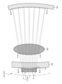
- Figures 1 and 2 show the appearance of a projection device 1 that projects a dot matrix image onto the retina of the eye.
- a projection device 1 that projects a dot matrix image onto the retina of the eye.
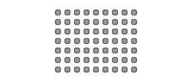
- one opening of a rectangular frame 2 is closed by a sealing glass 3 that is transparent in the visible range (see Figure 1), and the other opening of the main frame 2 is closed by a small LED array substrate 4 (see Figure 2), and multiple light irradiation units 5 are arranged at equal intervals inside.
- the number of light irradiation units 5 that irradiate light in the visible range is not particularly limited, but by arranging, for example, 640 dots in the horizontal direction and 480 dots in the vertical direction, the projection device 1 can project a 640 x 480 dot matrix image with each light irradiation unit 5 as an individual pixel. Note that, with a general technology for constructing an LED array on a substrate, it is possible to realize an LED element size of 1 [ ⁇ m] x 1 [ ⁇ m], so an LED array substrate 4 of about 640 x 480 can be formed as small as about 2 [mm] x 1.5 [mm].
- the projection device 1 is very small, and even if it is placed on the cornea of the eye and made to face the retina, it is not focused and the irradiation surface 1a cannot be recognized.
- the projection device 1 of this embodiment can project an enlarged dot matrix image similar to the two-dimensional shape (for example, a horizontally elongated rectangular shape of 640:480) formed by the arrangement of each light irradiation unit 5 onto the retina by the irradiation light adjustment means provided in each light irradiation unit 5, so that the irradiation content of the irradiation surface 1a can be recognized by the eye.
- the irradiation light adjustment means provided in each light irradiation unit 5 converts the diffused light from the LED elements (point light sources) that are the light-emitting elements of the LED array substrate 4 as the light-emitting element array substrate into parallel light, and adjusts the optical axis so that the irradiation direction corresponds to the distance and direction from the center area CA of the irradiation surface 1a to each light irradiation unit 5.
- the light-emitting element is not limited to the LED element, and an organic EL element may be used. If the light irradiation unit 5 is provided on an organic EL array substrate in which organic EL elements as point light sources are arrayed, it functions as a similar irradiation light adjustment means.
- each light irradiation section 5 functions as one pixel, but the adjustment contents of the irradiation light adjustment means differ depending on the position of the pixel. Therefore, for the sake of convenience, in the following, the pixel in the first row and first column will be referred to as light irradiation section 5 (1, 1), the pixel in the 480th row and 640th column will be referred to as light irradiation section 5 (480, 640), and so on.
- the light irradiation units 5 are arranged in an even number x even number matrix as in this embodiment, there are no light irradiation units 5 in the central area CA of the irradiation surface 1a, and light irradiation units 5 (240, 320), 5 (240, 321), 5 (241, 320), and 5 (241, 321) are adjacent to the central area CA.
- the light irradiation units 5 (240, 320), 5 (240, 321), 5 (241, 320), and 5 (241, 321) adjacent to the central area CA are projected onto the virtual screen VS as projected dots PD (240, 320), PD (240, 321), PD (241, 320), and PD (241, 321). Since the light irradiation unit 5 (240, 320) is located diagonally above and to the right of the central area CA facing the virtual screen VS, the irradiation direction is diagonally above and to the right, and since the distance from the central area CA is very short, the inclination angle with respect to the perpendicular line perpendicular to the irradiation surface 1a is also small.
- the light irradiation unit 5 (240, 321) is located diagonally above the left of the central area CA toward the virtual screen VS, so the irradiation direction is diagonally upward to the left, and since the distance from the central area CA is very short, the inclination angle with respect to the perpendicular line perpendicular to the irradiation surface 1a is also small.
- the light irradiation unit 5 (241, 320) is located diagonally below the right of the central area CA toward the virtual screen VS, so the irradiation direction is diagonally downward to the right, and since the distance from the central area CA is very short, the inclination angle with respect to the perpendicular line perpendicular to the irradiation surface 1a is also small.
- the light irradiation unit 5 (241, 321) is located diagonally below the left of the central area CA toward the virtual screen VS, so the irradiation direction is diagonally downward to the left, and since the distance from the central area CA is very short, the inclination angle with respect to the perpendicular line perpendicular to the irradiation surface 1a is also small.
- the light irradiation units 5(1,1), 5(1,640), 5(480,1), and 5(480,680), which are the furthest from the central area CA, are projected onto the virtual screen VS as the projected dots PD(1,1), PD(1,640), PD(480,1), and PD(480,640).
- the light irradiation unit 5(1,1) is located diagonally above the central area CA toward the virtual screen VS, so the irradiation direction is diagonally upward to the right, and since the distance from the central area CA is the longest, the inclination angle with respect to the perpendicular line perpendicular to the irradiation surface 1a is also large.
- the light irradiation unit 5(1,640) is located diagonally above the central area CA toward the virtual screen VS, so the irradiation direction is diagonally upward to the left, and since the distance from the central area CA is the longest, the inclination angle with respect to the perpendicular line perpendicular to the irradiation surface 1a is also large. Since the light irradiation unit 5 (480, 1) is located diagonally below the center area CA toward the virtual screen VS, the irradiation direction is diagonally below the right, and since the distance from the center area CA is the longest, the inclination angle with respect to the perpendicular line perpendicular to the irradiation surface 1a is also large.
- the light irradiation unit 5 (480, 680) is located diagonally below the center area CA toward the virtual screen VS, the irradiation direction is diagonally below the left, and since the distance from the center area CA is the longest, the inclination angle with respect to the perpendicular line perpendicular to the irradiation surface 1a is also large.
- the projection dots PD (1, 1), PD (1, 640), PD (480, 1), and PD (480, 640) projected on the virtual screen VS are in a state in which the distance between them is increased without changing the relative positions.
- the shape of the light irradiation surface of the light irradiation unit 5 is not limited to a square shape, but may be a round shape, a triangular shape, or a polygonal shape with pentagons or more.
- the light irradiation unit 5 is not limited to one that forms dots by emitting or not emitting light in a single color, but may form one pixel that can be displayed in color with three colors of RGB (or four colors of RGBW).
- this contact lens with projection function 101 is attached to the center of the contact lens 10 so that the irradiation surface 1a of the projection device 1 faces the back surface 10b.
- the thickness of the projection device 1 (the front-to-back width of the main frame 2) can be formed to be about 0.2 mm to 0.5 mm, so the projection device 1 does not protrude from the front surface 10a of the contact lens 10 and can be contained within the thickness of the contact lens 10.
- the projection device 1 of this embodiment only functions as a projector, a power source for operating the projection device 1 and a function for transmitting and receiving image data projected by the projection device 1 are separately required.
- FIG. 5 shows a first example of a retinal projection system 100 consisting of a contact lens with projection function 101 and an external projection control device 20.
- the contact lens with projection function 101 is provided with a communication antenna 11, a communication and power supply control device 12, and a projection control device 13.
- the external projection control device 20 has a function for wirelessly supplying power to the contact lens with projection function 101, and a communication function for sending retinal projection instructions and image data for projection to the contact lens with projection function 101.
- the communication antenna 11 receives radio waves from the external projection control device 20, and the communication and power supply control device 12 performs communication and contactless power supply and transmits the necessary data to the projection control device 13, and retinal projection is performed by the projection device 1 under the control of this projection control device 13.
- FIG. 6 shows a second example of a retinal projection system 100' consisting of a contact lens with projection function 101', an external projection control device 20', and a wireless charger 30.
- the contact lens with projection function 101' is provided with a battery 14 in addition to a projection device 1, a communication antenna 11, a communication and power supply control device 12, and a projection control device 13.
- the external projection control device 20' has a communication function for instructing the contact lens with projection function 101' to perform retinal projection and transmitting image data for projection, but does not have a function for wirelessly supplying power to the contact lens with projection function 101'. For this reason, the contact lens with projection function 101' charges the battery 14 via the wireless charger 30 when the contact lens with projection function 101' is not in operation.
- the external projection control device 20 In the first example of the retinal projection system 100, the external projection control device 20 must continue to wirelessly power the contact lens 101 with projection function, so if the external projection control device 20 moves away from the contact lens 101 with projection function and exceeds the power supply distance, which is equal to or shorter than the communication distance, the contact lens 101 with projection function will no longer function.
- the contact lens 101' with projection function can still operate with power from the battery 14, so a message can be projected to the effect that data cannot be received from the external projection control device 20 to alert the user.
- each functional device is also integrated with the projection device 1 using a miniaturization process, all functions can be placed near the center of the contact lens 10 together with the projection device 1.
- the projection device 1 can be placed near the center of the contact lens 10, and the other functional devices can be provided in positions that do not block the pupil (for example, the periphery of the contact lens 10).
- Figure 7 shows an example of the arrangement of each functional device in a contact lens 101' with a projection function and a battery 14.
- a communication antenna 11 is arranged in a circular shape (for example, 13 mm in diameter) on the outermost periphery of the contact lens 10 and is connected to a communication and power supply control device 12.
- This communication and power supply control device 12 and projection control device 13 are connected via a circular wiring 15 provided inside the communication antenna 11.
- multiple batteries 14 are distributed along the wiring 15 and are connected to the communication and power supply control device 12 via the wiring 15 so that they can be charged and discharged.
- the projection control device 13 and the projection device 1 are connected via a wiring 16.
- This wiring 16 blocks the pupil in order to connect to the projection device 1 located near the center of the contact lens 10, but the width is only a few tenths of a millimeter, so it does not have a significant effect on narrowing the field of view of the person using the contact lens 101' with projection function.
- FIG. 8 shows the state in which the projection device 1 is placed on the cornea 102 by wearing the contact lens with projection function 101 (or the contact lens with projection function 101') on the eye.
- the projection device 1 is assumed to have light irradiation units 5 of 9 dots x 7 dots, and the process in which the light irradiated from light irradiation units 5 (1,1) to 5 (7,9) passes through the cornea 102 and the crystalline lens 103 to form an image on the retina 104 is shown.
- the light emitted from the irradiation surface 1a of the projection device 1 is incident on the cornea 102 as a dot matrix image (see FIG. 9) with an aspect ratio according to the arrangement of the light irradiation units 5 (1,1) to 5 (7,9). Since the arrangement intervals of the light irradiation units 5 (1,1) to 5 (7,9) are narrow, on the order of a few microns, the effect of refraction of the irradiated light from the cornea 102 is small, and the change in the optical path can be ignored, and a dot matrix image (see FIG. 10) that maintains the aspect ratio is incident on the crystalline lens 103.
- the crystalline lens 103 is a convex lens, the light beam that passes through the crystalline lens 103 is narrowed and projected onto the retina 104 (see FIG. 11). If each dot of the dot matrix image formed on the retina 104 is wide enough to stimulate the photoreceptor cells on the retina 104 individually, each dot of the dot matrix image can be recognized. That is, the text information and image information displayed by the light irradiation units 5 (1,1) to 5 (7,9), which are spaced closely together on the order of a few microns, are enlarged and projected onto the retina 104, allowing the text information and image information to be viewed.
- each light irradiation unit 5 does not necessarily need to be designed to be focused; it is sufficient if the crystalline lens 103 can be adjusted to focus on the text information and image information of the projection device 1 when a person wants to view the text information and image information of the projection device 1.
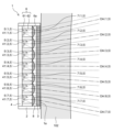
- each light irradiation unit 5 is not particularly limited, but FIG. 12 shows an example of a configuration for realizing an irradiation light adjustment means.
- FIG. 12 shows a schematic central vertical section of a projection device 1 equipped with light irradiation units 5 of 9 dots x 7 dots, and only light irradiation unit 5 (1, 5), light irradiation unit 5 (2, 5), light irradiation unit 5 (3, 5), light irradiation unit 5 (4, 5), light irradiation unit 5 (5, 5), light irradiation unit 5 (6, 5), and light irradiation unit 5 (7, 5) in the first to seventh rows of five rows are visible.
- the center of light irradiation unit 5 (4, 5) is the central area CA, so the irradiation direction of the other light irradiation units 5 is adjusted according to the distance and direction of separation from light irradiation unit 5 (4, 5).
- Each LED element 41 is surrounded by an isolation wall 6 to prevent the emitted light from mixing.
- the isolation wall 6 has, for example, a structure in which horizontal walls 61 and vertical walls 62 are arranged at equal intervals, dividing the space in front of each LED element 41 into a lattice shape and guiding the light emitted from each LED element 41 to the tip 6a of the isolation wall 6.
- a convex lens 7 corresponding to each light emitting section 5 is arranged at the tip 6a, which is the tip side of the isolation wall 6.
- a plano-convex lens is used as the convex lens 7, and the flat surface of the convex lens 7 is brought into close contact with the tip 6a of the isolation wall 6.
- a gas-filled cavity 8 is formed between the front side of each convex lens 7 and the sealing glass 3, and an inert gas such as nitrogen or helium is filled therein.
- the convex lenses 7 are microlenses with a curvature and medium such that the light irradiated from each LED element 41 becomes nearly parallel when it passes through the gas-filled cavity 8. That is, when the light irradiated from the LED element 41 of each light irradiating unit 5 passes through the convex lens 7 and reaches the gas-filled cavity 8, it passes through the sealing glass 3 as approximately parallel light and is irradiated from the irradiation surface 1a.
- Such a light irradiating unit 5 can be easily realized by applying existing image sensor technology.
- the image sensor focuses parallel light from a subject or the like with a convex lens and focuses the light on the light receiving unit of a CCD or CMOS sensor
- an LED element 41 is placed as a point light source instead of a CCD or CMOS sensor, it is possible to convert the light irradiated from the LED element 41 into parallel light and output it.
- LED elements are easier to make than CCDs or CMOS sensors, and have the advantage that the projection device 1 can be manufactured at low cost.
- the relationship between the optical axis of the irradiation light irradiated from each LED element 41 and the central position of the convex lens 7 is adjusted.
- the optical axis of the light irradiated from the LED element 41 (4,5) is aligned with the central position of the convex lens 7 (4,5) 7, so that the optical axis OA (4,5) travels straight.
- the central position of the convex lens 7 (3,5) is shifted slightly upward with respect to the optical axis of the light irradiated from the LED element 41 (3,5), so that the optical axis OA (3,5) is adjusted to face upward.
- the center position of the convex lens 7 (5,5) is shifted slightly downward with respect to the optical axis of the light irradiated by the LED element 41 (5,5), so that the optical axis OA (5,5) is adjusted to face downward.
- the center position of the convex lens 7 (2,5) is shifted further upward with respect to the optical axis of the light irradiated by the LED element 41 (2,5), so that the optical axis OA (2,5) is adjusted to face further upward.
- the center position of the convex lens 7 (6,5) located below the light irradiation unit 5 (5,5) is shifted further downward with respect to the optical axis of the light irradiated by the LED element 41 (6,5), so that the optical axis OA (6,5) is adjusted to face further downward.
- the center position of the convex lens 7 (1,5) is further shifted upward with respect to the optical axis of the light emitted by the LED element 41 (1,5), so that the optical axis OA (1,5) is adjusted to face further upward.
- the center position of the convex lens 7 (7,5) located below the light irradiation unit 5 (6,5) is further shifted downward with respect to the optical axis of the light emitted by the LED element 41 (7,5), so that the optical axis OA (7,5) is adjusted to face further downward.
- the irradiation light adjustment means which is composed of a partition wall 6 surrounding each LED element 41 on the LED array board 4 and a convex lens 7 arranged at the tip side of the partition wall 6, converts the irradiation light from each LED element 41 into parallel light by each convex lens 7, and by adjusting the amount and direction of displacement of the center position of each convex lens 7 relative to the optical axis of the irradiation light from each LED element 41, it is possible to adjust the optical axis so that the irradiation direction corresponds to the distance and direction of separation from the central area CA of the irradiation surface 1a to each light irradiation section 5.
- each convex lens 7 When a biconvex lens is used as the convex lens 7, the curvature and medium of each convex lens 7 can be set so that the light emitted from each LED element 41 can be converted into parallel light, taking into account both the incident refraction from the isolation wall 6 side to the convex lens 7 and the outgoing refraction from the convex lens 7 to the gas-filled space 8. Also, if the convex lenses 7(1,1) to 7(7,9) are formed as an integrated lens array (see FIG.
- each LED element 41 on the LED array board 4 is used as a point light source, and an external laser light source or the like is not required, making it easy to use. Moreover, the current-driven LED elements 41 make it easy to control the light emission intensity, and text information and image information can be safely projected without damaging the retina 104.
- the contact lens 101 with the projection function to which the projection device 1 is attached can place the projection device 1 on the cornea 102 with the irradiation surface 1a of the projection device 1 facing the retina 104. If the contact lens 101 with the projection function is worn on only one eye, the projection image from the projection device 1 can be seen at the same time as the field of view of the other eye, making it easy to use as an AR device. In addition, if the projection device 1 is placed near the center of the contact lens 101 with the projection function, a dot matrix image is projected near the fovea on the retina 104, which has the advantage of high resolution.
- the contact lens 101 with the projection function when the eye is moved, the contact lens 101 with the projection function also moves at the same time while being attached to the cornea 102, so the dot matrix image generated by the projection device 1 is seen at the center of the place of interest. Furthermore, if a system for recognizing eye movement information is added to the contact lens 101 with the projection function, field of view information according to eye movement can be identified, and a function for displaying information corresponding to the place or building that the person is trying to see by the projection device 1 can be realized.
- Projection device 1a Irradiation surface 2 Main frame 3 Sealing glass 4 LED array substrate 41 LED element 5 Light irradiation section 6 Isolation wall 6a Tip 61 Horizontal wall 62 Vertical wall 7 Convex lens 8 Gas-filled space 10 Contact lens 10a Front surface 10b Back surface 11 Communication antenna 12 Communication and power supply control device 13 Projection control device 14 Battery 20, 20' External projection control device 30 Wireless charger 100, 100' Retinal projection system 101, 101' Contact lens with projection function 102 Cornea 103 Lens 104 Retina
Landscapes
- Physics & Mathematics (AREA)
- General Physics & Mathematics (AREA)
- Optics & Photonics (AREA)
- Health & Medical Sciences (AREA)
- Ophthalmology & Optometry (AREA)
- General Health & Medical Sciences (AREA)
- Liquid Crystal (AREA)
Abstract
L'invention concerne un dispositif de projection qui présente une facilité d'utilisation élevée et qui peut projeter de manière stable une vidéo sur une rétine. Un dispositif de projection 1 est disposé sur une cornée 102 en portant une lentille de contact 101 ayant une fonction de projection sur un œil. Des faisceaux lumineux émis à partir d'unités d'émission de lumière respectives 5 du dispositif de projection 1 sont convertis en faisceaux lumineux parallèles, ont les directions d'émission respectives changées en un motif radial dans lequel une région centrale CA est située au centre, et sont émis à partir d'une surface d'émission 1a. Par conséquent, une image de matrice de points qui est transmise à travers la cornée 102 et une lentille cristalline 103 et qui est agrandie tout en maintenant une forme similaire est projetée sur une rétine 104.
Priority Applications (1)
| Application Number | Priority Date | Filing Date | Title |
|---|---|---|---|
| PCT/JP2022/040324 WO2024089869A1 (fr) | 2022-10-28 | 2022-10-28 | Dispositif de projection et lentille de contact ayant une fonction de projection |
Applications Claiming Priority (1)
| Application Number | Priority Date | Filing Date | Title |
|---|---|---|---|
| PCT/JP2022/040324 WO2024089869A1 (fr) | 2022-10-28 | 2022-10-28 | Dispositif de projection et lentille de contact ayant une fonction de projection |
Publications (1)
| Publication Number | Publication Date |
|---|---|
| WO2024089869A1 true WO2024089869A1 (fr) | 2024-05-02 |
Family
ID=90830349
Family Applications (1)
| Application Number | Title | Priority Date | Filing Date |
|---|---|---|---|
| PCT/JP2022/040324 WO2024089869A1 (fr) | 2022-10-28 | 2022-10-28 | Dispositif de projection et lentille de contact ayant une fonction de projection |
Country Status (1)
| Country | Link |
|---|---|
| WO (1) | WO2024089869A1 (fr) |
Citations (5)
| Publication number | Priority date | Publication date | Assignee | Title |
|---|---|---|---|---|
| JPH10319342A (ja) * | 1997-05-15 | 1998-12-04 | Olympus Optical Co Ltd | 眼球投影型映像表示装置 |
| JP2018092111A (ja) * | 2016-11-25 | 2018-06-14 | 株式会社ユニバーサルビュー | ピンホールコンタクトレンズ及びスマートコンタクトシステム |
| JP2019056937A (ja) * | 2018-12-28 | 2019-04-11 | 株式会社ニコン | ヘッドマウントディスプレイ |
| JP2019152851A (ja) * | 2018-02-28 | 2019-09-12 | シャープ株式会社 | 表示素子及び表示装置 |
| WO2021111792A1 (fr) * | 2019-12-02 | 2021-06-10 | ソニーグループ株式会社 | Dispositif d'affichage et système d'affichage |
-
2022
- 2022-10-28 WO PCT/JP2022/040324 patent/WO2024089869A1/fr unknown
Patent Citations (5)
| Publication number | Priority date | Publication date | Assignee | Title |
|---|---|---|---|---|
| JPH10319342A (ja) * | 1997-05-15 | 1998-12-04 | Olympus Optical Co Ltd | 眼球投影型映像表示装置 |
| JP2018092111A (ja) * | 2016-11-25 | 2018-06-14 | 株式会社ユニバーサルビュー | ピンホールコンタクトレンズ及びスマートコンタクトシステム |
| JP2019152851A (ja) * | 2018-02-28 | 2019-09-12 | シャープ株式会社 | 表示素子及び表示装置 |
| JP2019056937A (ja) * | 2018-12-28 | 2019-04-11 | 株式会社ニコン | ヘッドマウントディスプレイ |
| WO2021111792A1 (fr) * | 2019-12-02 | 2021-06-10 | ソニーグループ株式会社 | Dispositif d'affichage et système d'affichage |
Similar Documents
| Publication | Publication Date | Title |
|---|---|---|
| KR102625625B1 (ko) | 투사형 3d 라이트 필드 생성을 위한 라이트 필드 이미지 방법 및 장치 | |
| EP3384337B1 (fr) | Système de projection d'images | |
| US20170301270A1 (en) | Imaging Structure Emitter Configurations | |
| CN104254800B (zh) | 图像生成系统及图像生成方法 | |
| US9726887B2 (en) | Imaging structure color conversion | |
| CN108375840B (zh) | 基于小型阵列图像源的光场显示单元及使用其的三维近眼显示装置 | |
| CA2220283C (fr) | Afficheur retinien virtuel a source ponctuelle par fibre optique | |
| US7564630B2 (en) | Scanning image display apparatus | |
| US5311220A (en) | Autostereoscopic display | |
| US6813085B2 (en) | Virtual reality display device | |
| EP1310819B1 (fr) | Appareil optique autostéréoscopique avec source d'image linéaire à balayage | |
| CA2147634C (fr) | Affichage virtuel de la retine | |
| WO2015129584A1 (fr) | Appareil de projection | |
| JPH07506220A (ja) | 垂直キャビティ・面発光レーザアレイディスプレイシステム | |
| US20130207964A1 (en) | Imaging structure with embedded light sources | |
| US6781760B2 (en) | Display device | |
| CN107561701B (zh) | 近眼显示系统、虚拟现实设备及增强现实设备 | |
| CN105934902A (zh) | 虚拟和增强现实系统与方法 | |
| JP6535340B2 (ja) | 表示装置 | |
| KR20140128134A (ko) | 단일 방향성의 빔을 이용한 영상 표시 장치, 증강 현실 영상 구현 방법 및 장치 | |
| US10417950B2 (en) | Subpixel layouts for eye-mounted displays | |
| WO2024089869A1 (fr) | Dispositif de projection et lentille de contact ayant une fonction de projection | |
| US12007661B2 (en) | Display apparatus | |
| CN112600995A (zh) | 摄像头组件及其标定方法、电子设备 | |
| WO2020159883A1 (fr) | Système d'affichage comportant un réseau de pixels unidimensionnel pourvu d'un miroir de balayage |
Legal Events
| Date | Code | Title | Description |
|---|---|---|---|
| 121 | Ep: the epo has been informed by wipo that ep was designated in this application |
Ref document number: 22963516 Country of ref document: EP Kind code of ref document: A1 |