WO2024085151A1 - 筆記具の替芯パッケージ及び替芯セット - Google Patents
筆記具の替芯パッケージ及び替芯セット Download PDFInfo
- Publication number
- WO2024085151A1 WO2024085151A1 PCT/JP2023/037572 JP2023037572W WO2024085151A1 WO 2024085151 A1 WO2024085151 A1 WO 2024085151A1 JP 2023037572 W JP2023037572 W JP 2023037572W WO 2024085151 A1 WO2024085151 A1 WO 2024085151A1
- Authority
- WO
- WIPO (PCT)
- Prior art keywords
- refill
- lead
- package
- storage chamber
- flat plate
- Prior art date
- Legal status (The legal status is an assumption and is not a legal conclusion. Google has not performed a legal analysis and makes no representation as to the accuracy of the status listed.)
- Ceased
Links
Images




Classifications
-
- B—PERFORMING OPERATIONS; TRANSPORTING
- B43—WRITING OR DRAWING IMPLEMENTS; BUREAU ACCESSORIES
- B43K—IMPLEMENTS FOR WRITING OR DRAWING
- B43K31/00—Writing implement receptacles functioning as, or combined with, writing implements
- B43K31/005—Distributors for leads, cartridges and the like
-
- B—PERFORMING OPERATIONS; TRANSPORTING
- B43—WRITING OR DRAWING IMPLEMENTS; BUREAU ACCESSORIES
- B43K—IMPLEMENTS FOR WRITING OR DRAWING
- B43K19/00—Non-propelling pencils; Styles; Crayons; Chalks
- B43K19/14—Sheathings
-
- B—PERFORMING OPERATIONS; TRANSPORTING
- B65—CONVEYING; PACKING; STORING; HANDLING THIN OR FILAMENTARY MATERIAL
- B65D—CONTAINERS FOR STORAGE OR TRANSPORT OF ARTICLES OR MATERIALS, e.g. BAGS, BARRELS, BOTTLES, BOXES, CANS, CARTONS, CRATES, DRUMS, JARS, TANKS, HOPPERS, FORWARDING CONTAINERS; ACCESSORIES, CLOSURES, OR FITTINGS THEREFOR; PACKAGING ELEMENTS; PACKAGES
- B65D83/00—Containers or packages with special means for dispensing contents
- B65D83/02—Containers or packages with special means for dispensing contents for dispensing rod-shaped articles, e.g. needles
Definitions
- This invention relates to a refill set that includes a refill package capable of storing a relatively large amount of refills for writing implements, and a refill case capable of storing refills dispensed from the package.
- Patent document 1 discloses a replacement lead case having a cylindrical body made of paper with a disk-shaped bottom plate attached to the lower end and a cylindrical lid body made of paper with a top plate attached in a rotatable manner to the top of the cylindrical body.
- the refill lead stored inside the cylindrical body can be removed through the notch by aligning the notch formed on the cylindrical body with the notch formed on the top plate of the lid.
- Patent Document 2 discloses a refill case in which an inner case for accommodating refills is inserted into an outer case so as to be movable up and down, and a lid that pivots to open and close is formed on the upper end of the inner case.
- a tongue is provided at the top of the pivotable lid that engages with a part of the outer case, and the lid is opened by the engagement of the tongue with the outer case as the inner case rises.
- the outer case and the inner case are each made of paper and are folded and molded.
- Patent Document 3 discloses a refill cartridge comprising an inner paper case in the shape of a rectangular tube that houses a refill cartridge, and an outer paper case in the shape of a rectangular tube that covers the inner case.
- a lead removal opening is formed in the corner of the top panel of the inner case, and a hinged opening and closing part that can cover the top panel of the inner case is formed on the outer case. Therefore, by opening the hinged opening and closing part, a replacement lead can be removed from the lead removal opening of the inner case.
- the refill cartridge cases made from paper as mentioned above are all constructed by combining two or more components, such as an inner case and an outer case, and mass-producing them requires automatic machines that can fold and shape the paper material that makes up the inner and outer cases, which inevitably leads to a rise in the manufacturing costs of the refill cartridge cases.
- lead replacements for mechanical pencils are provided in lead replacement cases, stored in units of several dozen (for example, 40), and when the lead replacements are used up, the lead replacement cases are also disposed of. Therefore, the lead replacement cases are discarded without achieving sufficient usage to justify the manufacturing costs of the lead replacement cases.
- This invention was made in response to the above-mentioned situation, and aims to create a refill package capable of storing a relatively large amount of refills for writing instruments, using so-called cardboard in order to contribute to reducing the amount of plastic material used, and to enable one or more refills to be removed in small portions from the refill package and transferred to a refill case for use.
- This aims to provide a refill lead package and a refill lead set for a writing instrument that achieves a plastic-free product while preventing a rise in manufacturing costs.
- the refill lead package for a writing instrument which was made to solve the above-mentioned problems, is composed of a flat cardboard body with a corrugated paper-based core and a paper-based liner attached to both sides of the core, and is characterized in that the linear space formed between the core and the liner serves as a refill lead storage chamber, and the refill lead for the writing instrument is stored in the refill lead storage chamber.
- a lead removal opening for the lead storage chamber is formed at the end of the flat plate, and a label sticker covering the lead removal opening is affixed to the flat plate.
- a part of the refill cartridge chamber is set as an empty refill cartridge chamber that does not contain a refill cartridge, and the refill cartridges are intermittently stored in the refill cartridge chamber in groups of multiple small refill cartridges, except for the empty refill cartridge chamber.
- the flat plate is also provided with a compression closure in a direction perpendicular to the surface of the flat plate, so that one of the linear spaces forming the refill cartridge chamber is closed.
- the refill set for a writing instrument is provided in a form including the refill package for the writing instrument described above and a refill case capable of storing one or more refills removed from the refill package for the writing instrument.
- the refill lead package for the writing instrument according to the present invention described above is composed of a flat plate of cardboard with liners attached to both sides of a corrugated core.
- the linear space formed between the core and the liner serves as a refill lead storage chamber, and the writing instrument is provided with the refill lead stored in the refill lead storage chamber.
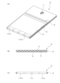
- FIG. 1A and 1B show a refill lead package according to the present invention, in which FIG. 1A is a perspective view of the refill package from the front side, FIG. 1B is an end view of the upper part, and FIG. 1C is an end view of the lower part.
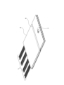
- 1 shows an example of assembly of a flat plate that constitutes a refill package, where (A) shows the state before the core and liner are joined, (B) shows the joined state, and (C) shows the state after a compression closure portion etc. has been applied.
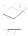
- 1 is a perspective view showing a state in which a refill is filled into a refill package.
- FIG. 1A is a perspective view of the refill package from the front side
- FIG. 1B is an end view of the upper part
- FIG. 1C is an end view of the lower part.
- 1 shows an example of assembly of a flat plate that constitutes a refill package, where (A) shows the state before the core and liner are joined, (B) shows the joined state, and (C) shows the
- FIG. 1A and 1B show a preferred embodiment in which a refill package is filled with refills, in which (A) is a perspective view and (B) is an end view of the lower part of the refill package.
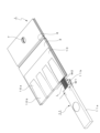
- 13A and 13B show the state in which a refill is being removed from a refill package, in which FIG. 1 is a perspective view showing the state in which refills are being refilled from a refill package into a refill case, with the refill case facing forward.
- FIG. FIG. 2 is a perspective view showing the refill package facing forward.
- FIGS. 1 to 6 show a refill package for a writing instrument
- Figures 1 and 2 show the external configuration of the entire refill package.
- This refill package 1 is composed of a flat plate body 2 made by forming corrugated cardboard, which is made of paper, into a rectangular shape. Examples of the components that make up this flat cardboard body 2 are shown in Figure 3.
- the flat cardboard body 2 is composed of a corrugated core 3 made of a paper base material, a front liner 4 made of a paper base material and arranged on both sides of the core 3, and a back liner 5, as shown in Figure 3 (A).
- a compressed closure section 6 is formed in a direction that crosses the wavy pattern on the core 3 as shown in Figure 3(C), and this compressed closure section 6 is formed in a straight line by compressing and concaving the flat body 2 from both the front and back sides.
- the positions of one of the concave and convex teeth of the upper and lower opposing jigs used to form the compressed closure portion 6 are shifted from each other in the linear direction, i.e., arranged so that the concave and convex portions face each other, thereby effectively imparting concave and convex marks from front to back along the longitudinal direction of the compressed closure portion 6.
- This makes it difficult for the front liner 4 and the back liner 5, which are centered around the core 3, to peel off, and allows the shape of the compressed closure portion 6 to be maintained for a long period of time.
- the compression closing portion 6 closes one side (upper portion) of each of the replacement lead accommodating chambers 8 formed of a number of linear spaces formed in parallel to each other, which will be described later.
- a hanging hole 7 formed in a circular shape is formed in the center of the upper part of the compression closure portion 6, which is used to hang the refill package 1 from a bar hook for hanging products when it is displayed and sold at a stationery store or the like.
- the compression closing portion 6 and the hanging hole 7 can be formed simultaneously on the flat plate body 2 .
- FIGS. 4 and 5 show examples of the state in which refills are stored in the refill chambers formed in the flat plate 2 made of the above-mentioned corrugated cardboard, and a preferable arrangement of the refills stored in the refill chambers.
- the linear space formed between the corrugated core 3 and the front and back liners 4, 5 is utilized as a replacement core storage chamber 8.
- a large number of linear spaces arranged vertically form refill lead storage chambers 8 [see Figure 5 (B)].
- the lower end of the flat body 2 in the refill lead package 1 in the suspended state serves as a refill lead removal opening 9 which also serves as an insertion opening for the refill lead L.
- a part of the refill lead storage chamber 8 is set as an empty refill lead storage chamber that does not store a refill lead L, and the refill leads L are stored in the refill lead storage chamber 8 intermittently, except for the empty refill lead storage chamber, in groups of multiple (e.g., 40) small refill leads for mechanical pencils (see FIG. 5).
- four sets of refills L are accommodated in one refill package 1 (see FIG. 4).
- a label sticker 10 is attached from the front side (front liner 4) to the back side (back liner 5) of the refill cartridge chamber 8, and this label sticker 10 seals the refill cartridge removal opening 9 formed at the lower end of the flat plate body 2. This prevents the four sets of refill cartridges L stored in the refill cartridge chamber 8 from scattering.
- the label sticker 10 has flaps 10a that are not glued on the back side of the lead refill package 1 shown in Fig. 1(B) corresponding to the storage positions of the four sets of lead refills L. Following the flaps 10a, a glued peelable portion 10b surrounded by perforations is formed in a rectangular shape. The peelable portion 10b surrounded by perforations continues to the front side of the lead refill package 1 as shown in Fig. 1(A). Therefore, the user can remove one set (40 refills) of refills L from the refill package 1 by pinching any one of the flaps 10a formed on the label sticker 10 and peeling off the peel-off portion 10b.
- FIG. 6 shows an example in which the refill L of the set on the right side is taken out with the refill package 1 turned over.
- a set of refills L divided from the refill package 1 can be refilled into an existing refill case and used, so even if the refill case that contains the divided refills is made of a resin material, it can be used continuously and not thrown away.
- FIGS. 7 and 8 show an example in which the refill lead package 1 and the refill lead case 11 are provided as a refill lead set in the case where the user does not have the refill lead case.
- the refill lead case 11 shown in this example can accommodate a set of refill leads L (40 pieces) divided from the refill lead package 1, and as shown in Figure 7, the width dimension W1 of the refill lead storage opening formed in the refill lead case 11 is set to a wide opening relationship (W1 > W2) relative to the overall width dimension W2 of the set of refill leads L when divided and stored in the refill lead package 1.
- the refill case 11 is attached to the cover member 11a so that the case body 11b on the back side can slide forward relative to the cover member 11a.
- the tip of the case body 11b bends toward the back side and deforms, opening the refill storage port.
- the refill lead case 11 is positioned diagonally below the refill lead package 1, and the refill leads L are slid from the refill lead package 1 toward the refill lead case 11 and poured into the open refill lead storage opening, allowing the entire set of refill leads L to be smoothly transferred to the refill lead case 11 side.
- the applicant has previously filed an application for the replacement lead case 11, which has been published as Japanese Patent Application Laid-Open No. 2022-96637.
- the refill package and refill set for a writing instrument according to the present invention can achieve the effects described in the Effects of the Invention section above, such as making it possible to eliminate the use of plastic and preventing rising manufacturing costs.
- the refill lead package 1 has been described as an example of storing refills for mechanical pencils.
- the refill lead package of the present invention is not limited to storing refills for mechanical pencils, and can achieve the same effects even if it stores, for example, refills for ballpoint pens (ballpoint pen refills).
- the refill package and refill set for a writing instrument according to the present invention are useful as one approach to global environmental issues (promoting a shift away from plastic).
Landscapes
- Engineering & Computer Science (AREA)
- Mechanical Engineering (AREA)
- Packaging Of Annular Or Rod-Shaped Articles, Wearing Apparel, Cassettes, Or The Like (AREA)
- Packages (AREA)
Abstract
Description
しかし、近年において海洋に流出するマイクロプラスチックの問題が注目されており、使い捨てを前提としたプラスチックの使用を控えるなど、地球環境問題に対する取り組みの機運が高まっている。
特許文献1には、紙素材による円筒状本体の下端に、円盤状の底板を取り付け、円筒状本体の上部に天板を備えた紙素材による円筒状の蓋体を回動可能に取り付けた替芯ケースが開示されている。
この替芯ケースによると、円筒状本体側に形成された切り欠きと、蓋体の天板に形成された切り欠きを一致させることで、切り欠きを介して円筒状本体内に収容された替芯を取り出すことができる。
この替芯ケースにおいては、回動開閉する蓋の上端に、外ケースの一部に係止する舌片が設けられており、中ケースの上昇に伴う外ケースへの前記舌片の係止作用により、開閉蓋を開くように構成されている。そして、前記外ケースと中ケースはそれぞれ紙素材を利用して折り曲げ成形されている。
内ケースの天面パネルの隅角部には芯取出し口が形成され、外ケースには内ケースの天面パネルを覆うことができるヒンジ開閉部が形成されている。従って、ヒンジ開閉部を開くことによって、内ケースの芯取り出し口から替芯を取り出すことができる。
また、シャープペンシル用の替芯は、替芯ケース内に数十本(例えば40本)程度の単位で収容されて提供されており、この替芯が使い終われば、替芯ケースも廃棄処理されることになる。従って、替芯ケースの製造コストに見合う十分な利用実績を果たすことなく替芯ケースは廃棄されるものとなる。
これにより、脱プラスチック化を図ると共に、製造コストの高騰を抑えた筆記具の替芯パッケージ及び替芯セットを提供することを課題とするものである。
先ず、図1~図6は筆記具の替芯パッケージについて示しており、図1及び図2は替芯パッケージ全体の外観構成を示している。この替芯パッケージ1は、紙を素材とした段ボールを矩形状に成形した平板体2により構成されている。
この段ボールによる平板体2を構成する各部材の例が図3に示されており、平板体2は図3(A)に示すように紙基材により波状に形成された中しん3と、前記中しん3の両面に配置される紙基材による表ライナ4と、裏ライナ5により構成される。
これにより、中しん3を中央とした表ライナ4と裏ライナ5が剥がれにくくなり、長期にわたり圧縮閉鎖部6の形態を維持させることができる。
なお、前記圧縮閉鎖部6は、後で説明する互いに平行状態に形成される多数の直線状空間部による替芯収容室8の各一方(上部)を閉塞するものとなる。
なお、前記圧縮閉鎖部6と吊り下げ孔7とは、平板体2に対して同時に成形加工することができる。
この実施の形態においては、前記した波状に形成された中しん3と、表裏のライナ4,5との間に形成された直線状空間部を替芯収容室8として利用している。
すなわち、替芯パッケージ1を吊り下げ孔7を利用して吊り下げた状態において、前記した圧縮閉鎖部6から下側の領域において、垂直方向に配列された多数の直線状空間部が、替芯収容室8〔図5(B)参照〕となる。
そして、吊り下げられた状態の替芯パッケージ1における平板体2の下端部が、替芯Lの挿入口を兼ねる替芯取出し口9となる。
そして、図示例においては、1つの替芯パッケージ1に4組の替芯Lが収容されるものとなる(図4参照)。
従って、ユーザーはラベルシール10に形成されたいずれかのフラップ10aをつまんで、剥離部10bを引き剥がすことで、一組(40本)の替芯Lを替芯パッケージ1から取り出すことができる。
なお、図6は、替芯パッケージ1を裏面にした状態で、向かって右側の組の替芯Lを、取り出す例を示している。
この例に示す替芯ケース11は、替芯パッケージ1から小分けした一組の替芯L(40本)を収容することができ、かつ図7に示すように替芯ケース11に形成された替芯収容口の幅寸法W1は、替芯パッケージ1に小分けして収容された状態の一組の替芯Lの全体の幅寸法W2に対して、広口となる関係(W1>W2)に設定されている。
なお、前記した替芯ケース11については、本出願人において先に出願をしており、これは、特開2022-96637号として公開されている。
なお、前記した実施の形態においては、替芯パッケージ1として、シャープペンシルの替芯を収容する例に基づいて説明したが、この発明に係る替芯パッケージは、シャープペンシルの替芯に限らず、例えばボールペンの替芯(ボールペンリフィル)を収容するものであっても、同様の作用効果を発揮することができる。
2 平板体
3 中しん
4 表ライナ
5 裏ライナ
6 圧縮閉鎖部
7 吊り下げ孔
8 替芯収容室
9 替芯取出し口
10 ラベルシール
10a フラップ
10b 剥離部
11 替芯ケース
11a カバー部材
11b ケース本体部
L 替芯
Claims (5)
- 紙基材により波状に形成された中しんと、前記中しんの両面に貼着された紙基材によるライナとを備えた段ボールによる平板体で構成され、
前記中しんとライナの間に形成された直線状空間部を替芯収容室として、当該替芯収容室内に筆記具の替芯を収容したことを特徴とする筆記具の替芯パッケージ。 - 前記平板体の端部には、前記替芯収容室の替芯取出し口が形成され、前記替芯取出し口を覆うラベルシールが、前記平板体に貼着されていることを特徴とする請求項1に記載の筆記具の替芯パッケージ。
- 前記替芯収容室の一部には、替芯を収容しない空き室の替芯収容室が設定され、前記替芯は小分けした複数本の替芯を組として、前記空き室となる替芯収容室を除いて、間欠的に前記替芯収容室に収容されていることを特徴とする請求項1に記載の筆記具の替芯パッケージ。
- 前記平板体には、平板体の面に直交する方向に圧縮閉鎖部が施されることで、前記替芯収容室を形成する前記直線状空間部の一方を閉塞したことを特徴とする請求項1に記載の筆記具の替芯パッケージ。
- 請求項1乃至4のいずれか1項に記載の筆記具の替芯パッケージと、当該筆記具の替芯パッケージから取り出された複数本の替芯を収容可能な替芯ケースとを含むことを特徴とする筆記具の替芯セット。
Priority Applications (2)
| Application Number | Priority Date | Filing Date | Title |
|---|---|---|---|
| KR1020247036315A KR20250088681A (ko) | 2022-10-18 | 2023-10-17 | 필기구의 교체심 패키지 및 교체심 세트 |
| CN202380036349.8A CN119255919A (zh) | 2022-10-18 | 2023-10-17 | 书写工具的替换芯包装体和替换芯组 |
Applications Claiming Priority (2)
| Application Number | Priority Date | Filing Date | Title |
|---|---|---|---|
| JP2022-166991 | 2022-10-18 | ||
| JP2022166991A JP7845984B2 (ja) | 2022-10-18 | 2022-10-18 | 筆記具の替芯パッケージ及び替芯セット |
Publications (1)
| Publication Number | Publication Date |
|---|---|
| WO2024085151A1 true WO2024085151A1 (ja) | 2024-04-25 |
Family
ID=90737807
Family Applications (1)
| Application Number | Title | Priority Date | Filing Date |
|---|---|---|---|
| PCT/JP2023/037572 Ceased WO2024085151A1 (ja) | 2022-10-18 | 2023-10-17 | 筆記具の替芯パッケージ及び替芯セット |
Country Status (4)
| Country | Link |
|---|---|
| JP (1) | JP7845984B2 (ja) |
| KR (1) | KR20250088681A (ja) |
| CN (1) | CN119255919A (ja) |
| WO (1) | WO2024085151A1 (ja) |
Citations (3)
| Publication number | Priority date | Publication date | Assignee | Title |
|---|---|---|---|---|
| JPS633220U (ja) * | 1986-06-25 | 1988-01-11 | ||
| DE19541443A1 (de) * | 1994-12-29 | 1996-07-04 | Caran D Ache Crayons | Verpackung für Bleistifte |
| JP2003080889A (ja) * | 2001-09-13 | 2003-03-19 | Mikuni Corp | 替芯ケース |
Family Cites Families (3)
| Publication number | Priority date | Publication date | Assignee | Title |
|---|---|---|---|---|
| JPH0723587A (ja) | 1993-06-22 | 1995-01-24 | Zexel Corp | 磁極検出回路及びそれを用いた三相ブラシレス同期電動機の駆動装置 |
| JP5049942B2 (ja) | 2008-10-28 | 2012-10-17 | キヤノン株式会社 | 復号装置、復号方法、及びプログラム |
| JP2011180090A (ja) | 2010-03-03 | 2011-09-15 | Nippon Telegr & Teleph Corp <Ntt> | アラーム装置 |
-
2022
- 2022-10-18 JP JP2022166991A patent/JP7845984B2/ja active Active
-
2023
- 2023-10-17 WO PCT/JP2023/037572 patent/WO2024085151A1/ja not_active Ceased
- 2023-10-17 KR KR1020247036315A patent/KR20250088681A/ko active Pending
- 2023-10-17 CN CN202380036349.8A patent/CN119255919A/zh active Pending
Patent Citations (3)
| Publication number | Priority date | Publication date | Assignee | Title |
|---|---|---|---|---|
| JPS633220U (ja) * | 1986-06-25 | 1988-01-11 | ||
| DE19541443A1 (de) * | 1994-12-29 | 1996-07-04 | Caran D Ache Crayons | Verpackung für Bleistifte |
| JP2003080889A (ja) * | 2001-09-13 | 2003-03-19 | Mikuni Corp | 替芯ケース |
Also Published As
| Publication number | Publication date |
|---|---|
| CN119255919A (zh) | 2025-01-03 |
| JP2024059361A (ja) | 2024-05-01 |
| JP7845984B2 (ja) | 2026-04-14 |
| KR20250088681A (ko) | 2025-06-17 |
Similar Documents
| Publication | Publication Date | Title |
|---|---|---|
| CN102448844B (zh) | 展示包装用品 | |
| CN102905992B (zh) | 钮扣电池分配封装件 | |
| US20090026209A1 (en) | Organizer system | |
| EP1515901B1 (en) | Packaging for disposable items | |
| BR112017028136B1 (pt) | Recipiente para bens de consumo com mecanismo de fechamento | |
| JP3192052U (ja) | デンタルフロスパッケージ | |
| US20050218027A1 (en) | Package with integral plug | |
| JP5719307B2 (ja) | ヒンジ蓋を有する容器 | |
| WO2024085151A1 (ja) | 筆記具の替芯パッケージ及び替芯セット | |
| WO2014054694A1 (ja) | 詰替え容器 | |
| ES2856298T3 (es) | Contenedor | |
| US20130129262A1 (en) | Flexible vase | |
| JP6186823B2 (ja) | 詰替え容器 | |
| JP4577767B2 (ja) | ブリスターパック | |
| CN87103414A (zh) | 包装结构 | |
| JP6554856B2 (ja) | ブリスターパック | |
| JP5739688B2 (ja) | 包装用箱 | |
| JP2025033577A (ja) | 文房具包装体 | |
| CN201086948Y (zh) | 纸制彩色笔包装盒 | |
| JP4649164B2 (ja) | 包装箱 | |
| JP6458592B2 (ja) | ブリスターパック | |
| CN208102882U (zh) | 组合式包装盒 | |
| TW202337787A (zh) | 裝有物品之包裝體、包裝體及裝有物品之包裝體之製造方法 | |
| JP2007244588A (ja) | 化粧用脂取りシート包装体 | |
| JP3106600U (ja) | 商品見本収納容器 |
Legal Events
| Date | Code | Title | Description |
|---|---|---|---|
| 121 | Ep: the epo has been informed by wipo that ep was designated in this application |
Ref document number: 23879794 Country of ref document: EP Kind code of ref document: A1 |
|
| WWE | Wipo information: entry into national phase |
Ref document number: 202380036349.8 Country of ref document: CN |
|
| WWP | Wipo information: published in national office |
Ref document number: 202380036349.8 Country of ref document: CN |
|
| NENP | Non-entry into the national phase |
Ref country code: DE |
|
| WWP | Wipo information: published in national office |
Ref document number: 1020247036315 Country of ref document: KR |
|
| 122 | Ep: pct application non-entry in european phase |
Ref document number: 23879794 Country of ref document: EP Kind code of ref document: A1 |