WO2024084724A1 - 制御装置、制御方法および空気調和機 - Google Patents
制御装置、制御方法および空気調和機 Download PDFInfo
- Publication number
- WO2024084724A1 WO2024084724A1 PCT/JP2023/015810 JP2023015810W WO2024084724A1 WO 2024084724 A1 WO2024084724 A1 WO 2024084724A1 JP 2023015810 W JP2023015810 W JP 2023015810W WO 2024084724 A1 WO2024084724 A1 WO 2024084724A1
- Authority
- WO
- WIPO (PCT)
- Prior art keywords
- value
- motor
- normalized
- pattern
- torque
- Prior art date
Links
- 238000000034 method Methods 0.000 title claims description 25
- 238000011156 evaluation Methods 0.000 claims abstract description 57
- 230000008859 change Effects 0.000 claims abstract description 27
- 238000010586 diagram Methods 0.000 description 17
- 230000008569 process Effects 0.000 description 14
- 230000006870 function Effects 0.000 description 12
- 238000006243 chemical reaction Methods 0.000 description 9
- 238000004378 air conditioning Methods 0.000 description 6
- 230000009471 action Effects 0.000 description 4
- 230000000694 effects Effects 0.000 description 4
- 238000012545 processing Methods 0.000 description 4
- 238000010606 normalization Methods 0.000 description 3
- 238000004891 communication Methods 0.000 description 2
- 230000003247 decreasing effect Effects 0.000 description 2
- 238000012986 modification Methods 0.000 description 2
- 230000004048 modification Effects 0.000 description 2
- 230000002093 peripheral effect Effects 0.000 description 2
- 239000003507 refrigerant Substances 0.000 description 2
- 230000006835 compression Effects 0.000 description 1
- 238000007906 compression Methods 0.000 description 1
- 238000012937 correction Methods 0.000 description 1
- 230000003111 delayed effect Effects 0.000 description 1
- 238000013461 design Methods 0.000 description 1
- 238000012544 monitoring process Methods 0.000 description 1
- 238000004549 pulsed laser deposition Methods 0.000 description 1
- 238000005070 sampling Methods 0.000 description 1
- 239000004065 semiconductor Substances 0.000 description 1
- 239000007787 solid Substances 0.000 description 1
Images


Classifications
-
- F—MECHANICAL ENGINEERING; LIGHTING; HEATING; WEAPONS; BLASTING
- F04—POSITIVE - DISPLACEMENT MACHINES FOR LIQUIDS; PUMPS FOR LIQUIDS OR ELASTIC FLUIDS
- F04B—POSITIVE-DISPLACEMENT MACHINES FOR LIQUIDS; PUMPS
- F04B49/00—Control, e.g. of pump delivery, or pump pressure of, or safety measures for, machines, pumps, or pumping installations, not otherwise provided for, or of interest apart from, groups F04B1/00 - F04B47/00
- F04B49/06—Control using electricity
-
- F—MECHANICAL ENGINEERING; LIGHTING; HEATING; WEAPONS; BLASTING
- F24—HEATING; RANGES; VENTILATING
- F24F—AIR-CONDITIONING; AIR-HUMIDIFICATION; VENTILATION; USE OF AIR CURRENTS FOR SCREENING
- F24F11/00—Control or safety arrangements
- F24F11/70—Control systems characterised by their outputs; Constructional details thereof
- F24F11/80—Control systems characterised by their outputs; Constructional details thereof for controlling the temperature of the supplied air
- F24F11/86—Control systems characterised by their outputs; Constructional details thereof for controlling the temperature of the supplied air by controlling compressors within refrigeration or heat pump circuits
-
- F—MECHANICAL ENGINEERING; LIGHTING; HEATING; WEAPONS; BLASTING
- F25—REFRIGERATION OR COOLING; COMBINED HEATING AND REFRIGERATION SYSTEMS; HEAT PUMP SYSTEMS; MANUFACTURE OR STORAGE OF ICE; LIQUEFACTION SOLIDIFICATION OF GASES
- F25B—REFRIGERATION MACHINES, PLANTS OR SYSTEMS; COMBINED HEATING AND REFRIGERATION SYSTEMS; HEAT PUMP SYSTEMS
- F25B1/00—Compression machines, plants or systems with non-reversible cycle
-
- H—ELECTRICITY
- H02—GENERATION; CONVERSION OR DISTRIBUTION OF ELECTRIC POWER
- H02P—CONTROL OR REGULATION OF ELECTRIC MOTORS, ELECTRIC GENERATORS OR DYNAMO-ELECTRIC CONVERTERS; CONTROLLING TRANSFORMERS, REACTORS OR CHOKE COILS
- H02P27/00—Arrangements or methods for the control of AC motors characterised by the kind of supply voltage
- H02P27/04—Arrangements or methods for the control of AC motors characterised by the kind of supply voltage using variable-frequency supply voltage, e.g. inverter or converter supply voltage
- H02P27/06—Arrangements or methods for the control of AC motors characterised by the kind of supply voltage using variable-frequency supply voltage, e.g. inverter or converter supply voltage using DC to AC converters or inverters
Definitions
- This disclosure relates to a control device, a control method, and an air conditioner.
- This application claims priority to Japanese Patent Application No. 2022-169319, filed on October 21, 2022, the contents of which are incorporated herein by reference.
- the control device described in Patent Document 1 suppresses motor speed fluctuations by compensating the output torque command according to the estimated rotor position using the product of the average torque and the normalized torque pattern.
- the normalized torque pattern described in Patent Document 1 is a pattern of coefficient values set for every 30 degrees of rotation angle of the motor rotor, for example, and the coefficient value of each section is normalized so that the product of the average torque and the coefficient value of each section matches the average torque in total over all sections.
- the normalized torque pattern is adjusted by multiplying the normalized torque pattern by one modulation factor selected from multiple modulation factors prepared in advance.
- This modulation factor is applied to the entire range or a portion of the motor rotation angle.
- the modulation factor is selected by increasing or decreasing the modulation factor set in multiple stages so that the estimated rotation speed fluctuation range is below a predetermined value or is at a minimum value while determining whether the estimated rotation speed fluctuation range has increased or decreased as a result of setting the modulation factor.
- the control device described in Patent Document 1 even if the waveform of the load torque of the compressor changes due to, for example, pressure fluctuations, the motor output torque can be appropriately matched to the load torque.
- Patent Document 1 also states that it may be possible to increase or decrease only a certain part of the normalized torque pattern, or to change the pattern, but does not mention any specific configuration.
- This disclosure has been made in consideration of the above circumstances, and aims to provide a control device, control method, and air conditioner that can appropriately adjust the normalized torque pattern.
- the control device is a control device that controls the rotation speed of the motor by controlling an inverter that drives an AC motor that rotates a compressor, calculates a compensation torque value by multiplying an average output torque command value calculated according to the deviation between the rotation speed of the motor and a rotation speed command value by a normalized torque pattern, which is a pattern of multiple coefficient values that change according to the rotation angle of the motor that is set so that the total value for one rotation is zero, and controls the inverter by setting the output torque command value of the motor according to the rotation angle by adding the compensation torque value to the average output torque command value, and compares the normalized torque pattern before adjustment with a normalized torque pattern after adjustment, which is a normalized torque pattern obtained by adjusting the multiple coefficient values individually using one of multiple bit patterns each having a bit number based on the number of the multiple coefficient values, based on the calculation results of a predetermined evaluation value related to the fluctuation in the rotation speed obtained as a result of actually using
- the control method is a control method for controlling the rotation speed of a motor by controlling an inverter that drives an AC motor to rotate a compressor, and calculates a compensation torque value by multiplying an average output torque command value calculated according to the deviation between the rotation speed of the motor and a rotation speed command value by a normalized torque pattern, which is a pattern of multiple coefficient values that change according to the rotation angle of the motor set so that the total value for one rotation is zero, and controls the inverter by setting the output torque command value of the motor according to the rotation angle by adding the compensation torque value to the average output torque command value, and compares the normalized torque pattern before adjustment with a normalized torque pattern after adjustment, which is a normalized torque pattern obtained by adjusting the multiple coefficient values individually using one of multiple bit patterns each having a bit number based on the number of the multiple coefficient values, based on the calculation results of a predetermined evaluation value related to the fluctuation in the rotation speed obtained as a result of actually using the normalized torque pattern to control the motor, and adopts one of the
- the air conditioner includes a compressor, a motor that drives the compressor to rotate, an inverter that drives the motor with an AC current, and a control device that controls the inverter to control the rotation speed of the motor, and calculates a compensation torque value by multiplying an average output torque command value calculated according to the deviation between the rotation speed of the motor and a rotation speed command value by a normalized torque pattern, which is a pattern of multiple coefficient values that change according to the rotation angle of the motor that is set so that the total value for one rotation is zero, and controls the inverter by setting the output torque command value of the motor according to the rotation angle by adding the compensation torque value to the average output torque command value, and compares the normalized torque pattern before adjustment with a normalized torque pattern after adjustment, which is a normalized torque pattern obtained by adjusting the multiple coefficient values individually using one of multiple bit patterns each having a bit number based on the number of the multiple coefficient values, based on the calculation results of a predetermined evaluation value related to the fluctuation in the rotation speed obtained as a result
- control device control method, and air conditioner disclosed herein can appropriately adjust the normalized torque pattern.
- FIG. 2 is a block diagram showing a configuration example of a control device for a motor connected to the air conditioning rotary compressor according to the first embodiment of the present disclosure.
- FIG. FIG. 4 is a schematic diagram showing a configuration example of a normalized torque pattern table according to the first embodiment of the present disclosure.
- FIG. 4 is a schematic diagram showing a configuration example of a normalized torque pattern table according to the first embodiment of the present disclosure.
- 5 is a flowchart showing an example of operation of the control device according to the first embodiment of the present disclosure.
- FIG. 4 is a schematic diagram showing an example of operation of the control device according to the first embodiment of the present disclosure.
- FIG. 11 is a schematic diagram showing a configuration example of a normalized torque pattern table according to a second embodiment of the present disclosure.
- FIG. 11 is a schematic diagram showing a configuration example of a normalized torque pattern table according to a second embodiment of the present disclosure.
- FIG. 13 is a block diagram showing an example configuration of a control device for a motor connected to an air conditioning rotary compressor according to a third embodiment of the present disclosure.
- FIG. 13 is a block diagram showing an example configuration of a control device for a motor connected to an air conditioning rotary compressor according to a fifth embodiment of the present disclosure.
- 13 is a flowchart showing an example of the operation of a control device according to a fifth embodiment of the present disclosure.
- FIG. 1 is a schematic block diagram illustrating a configuration of a computer according to at least one embodiment.
- Fig. 1 is a block diagram showing an example of the configuration of a control device for a motor connected to an air conditioning rotary compressor according to the first embodiment of the present disclosure.
- Figs. 2 and 3 are schematic diagrams showing an example of the configuration of a normalized torque pattern table according to the first embodiment of the present disclosure.
- Fig. 4 is a flowchart showing an example of the operation of a control device according to the first embodiment of the present disclosure.
- Fig. 5 is a schematic diagram showing an example of the operation of a control device according to the first embodiment of the present disclosure.
- Figs. 1 is a block diagram showing an example of the configuration of a control device for a motor connected to an air conditioning rotary compressor according to the first embodiment of the present disclosure.
- Figs. 2 and 3 are schematic diagrams showing an example of the configuration of a normalized torque pattern table according to the first embodiment of the present disclosure.
- Fig. 4 is a flowchart showing an example of the operation of a control device according to the first embodiment
- FIG. 6 and 7 are schematic diagrams showing an example of the configuration of a normalized torque pattern table according to the second embodiment of the present disclosure.
- Fig. 8 is a block diagram showing an example of the configuration of a control device for a motor connected to an air conditioning rotary compressor according to the third embodiment of the present disclosure.
- Fig. 9 is a block diagram showing an example of the configuration of a control device for a motor connected to an air conditioning rotary compressor according to the fifth embodiment of the present disclosure.
- Fig. 10 is a flowchart showing an example of the operation of a control device according to the fifth embodiment of the present disclosure.
- Fig. 11 is a schematic block diagram showing the configuration of a computer according to at least one embodiment. Note that the same or corresponding configurations in each figure are designated by the same reference numerals and the description will be omitted as appropriate.
- FIG. 1 shows a configuration example of a control device 1 according to the first embodiment of the present disclosure.
- the inverter 4 uses an AC power source 3 as a power source to supply power to the motor 2.
- the current sensor 10 detects the current value passed from the inverter 4 to the motor 2.
- the air conditioner 100 includes a control device 1, a motor 2, an inverter 4, and a current sensor 10.
- the control device 1 includes a computer such as a microcontroller, and peripheral devices and peripheral circuits of the computer.
- the control device 1 includes a subtraction unit 14, a speed control unit 20, a load torque compensation unit 13, a normalized torque pattern adjustment unit 26, a speed/position estimation unit 11, a two-phase/three-phase conversion unit 21, and a three-phase/two-phase conversion unit 22 as a functional configuration configured by a combination of hardware such as a computer and software such as a program executed by the computer.
- the speed control unit 20 includes a speed PI control unit (speed proportional integral control unit) 12 , an adder 15 , a current conversion unit 16 , a subtractor 17 , and a current PI control unit 18 .
- the control device is not limited to the example shown in FIG. 1, and may be any control device that controls a motor that drives a compressor such as a rotary compressor.
- the compressor is not limited to one provided in an air conditioner.
- FIG. 1 shows the main components related to the control of the rotation speed of the motor 2 by the control device 1, and some other components within the air conditioner 100 or control device 1, such as the refrigerant circuit, fan, and components related to temperature control and humidity control, are not shown.
- the three-phase/two-phase converter 22 receives the three-phase current values I detected by the current sensor 10 and the rotational position (rotational angle) ⁇ es of the rotor of the motor 2 estimated by the speed/position estimator 11, converts the three-phase current values I detected by the current sensor 10 into a d-axis current value id and a q-axis current value iq of two phases of the d-axis and q-axis, and outputs them.
- the two-phase/three-phase converter 21 receives the rotational position ⁇ es and the d-axis command voltage value vd* and the q-axis command voltage value vq* of two phases of the d-axis and q-axis output by the current PI control unit 18, converts them into three-phase voltage values V, and outputs them to the inverter 4.
- the inverter 4 controls a plurality of switching elements (not shown) provided in the inverter based on the three-phase voltage values V output by the two-phase/three-phase converter 21.
- the speed/position estimation unit 11 estimates the rotational position ⁇ es and rotational speed ⁇ mes of the rotor of the motor 2 based on the two-phase d-axis voltage value vd and q-axis voltage value vq output by the current PI control unit 18 and the two-phase d-axis current value id and q-axis current value iq output by the three-phase/two-phase conversion unit 22.
- the subtraction unit 14 subtracts the rotation speed ⁇ mes from the rotation speed command value ⁇ m* to calculate the deviation ⁇ m, and outputs it to the speed PI control unit 12 and the normalized torque pattern adjustment unit 26.
- the speed PI control unit 12 calculates an average torque command value, which is the average value of the output torque command value of the motor 2 for reducing the deviation ⁇ m by proportional-integral action with respect to the deviation ⁇ m, and outputs it to the adding unit 15 and the load torque compensation unit 13. In this case, the speed PI control unit 12 calculates and outputs the average output torque command value according to the deviation ⁇ m between the rotation speed ⁇ mes of the motor 2 and the rotation speed command value ⁇ m*.
- the load torque compensation unit 13 includes a normalized torque pattern table 131, and receives the average torque command value output by the speed PI control unit 12 and the rotational position ⁇ es output by the speed/position estimation unit 11. Using the normalized torque pattern table 131, the load torque compensation unit 13 calculates a compensation torque value and outputs it to the addition unit 15.
- the compensation torque value is a torque value for compensating for fluctuations in the load torque of the motor 2 during one rotation of the motor 2.
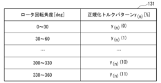
- the normalized torque pattern table 131 is a table that defines a normalized torque pattern, which is a pattern of multiple coefficient values that change according to the rotational position (rotational angle) ⁇ es of the motor 2.
- the load torque compensation unit 13 determines a coefficient value according to the rotational position (rotational angle) ⁇ es of the motor 2 based on the normalized torque pattern table 131, and calculates a compensation torque value by multiplying the average torque command value by the determined coefficient value.
- an output torque command value (output value of the adder 15) in which the fluctuation of the load torque is compensated according to the rotational position ⁇ es is calculated.
- the compensation torque value is a value that compensates for the load torque fluctuation during one rotation, and the average value of the output torque command value for one rotation compensated by the compensation torque value is required to match the average torque command value.
- the total value of the compensation torque value for one rotation is required to be zero.
- the sum of the coefficient values that make up (define) the normalized torque pattern over one rotation is also required to be zero.
- Figure 2 shows an example of the configuration of the normalized torque pattern table 131.
- Figure 3 shows an example of the relationship between the rotor rotation angle and multiple coefficient values, with the horizontal axis representing the rotor rotation angle [deg] and the vertical axis representing the coefficient value [%].
- the normalized torque pattern table 131 divides one rotation (360 degrees) into 12 intervals, each of which is divided into 30 degrees, and a coefficient value y(n)(m) is set for each interval.
- n represents the number of times the normalized torque pattern table 131 has been adjusted.
- a pattern consisting of the coefficient values y(n)(m) is called a normalized torque pattern y(n).
- the coefficient values y(n)(m) are set so that the total value for one rotation is zero.
- the number of divisions of the rotational position in the normalized torque pattern table 131 i.e., the number of divisions of the phase axis
- the phase axis of the normalized torque pattern is divided up to 2 x lcm(1, ..., k) x ndiv.
- 2 represents a coefficient based on the sampling theorem.
- lcm(1, ..., k) represents the least common multiple of the natural numbers from 1 to k.
- ndiv is an arbitrary natural number. This makes it possible to express torque fluctuations including harmonics up to the kth order. For example, when reducing the 1st to 3rd order components, when ndiv is 1, the number of divisions is 2 x 6 x 1, or 12 divisions.
- the adder 15 adds the average torque command value output by the speed PI control unit 12 and the compensation torque value output by the load torque compensation unit 13 to calculate the output torque command value, and outputs it to the current conversion unit 16.
- the current conversion unit 16 inputs the output torque command value output by the addition unit 15, converts the output torque command value into a current, calculates the d-axis command current value id* and the q-axis command current value iq*, and outputs them to the subtraction unit 17.
- the subtraction unit 17 inputs the d-axis command current value id*, the q-axis command current value iq*, and the d-axis current value id and the q-axis current value iq, subtracts the d-axis current value id and the q-axis current value iq from the d-axis command current value id* and the q-axis command current value iq*, respectively, calculates the deviations of the d-axis component and the q-axis component between the command value and the motor current value, and outputs them to the current PI control unit 18.
- the current PI control unit 18 calculates the d-axis command voltage value vd* and the q-axis command voltage value vq* to reduce each deviation output by the subtraction unit 17 through proportional-integral operation, and outputs them to the 2-phase/3-phase conversion unit 21 and the speed/position estimation unit 11.
- the normalized torque pattern adjustment unit 26 compares the normalized torque pattern before adjustment currently used as a reference with the normalized torque pattern after adjustment, which is a normalized torque pattern in which the multiple coefficient values are individually adjusted using one of multiple bit patterns each having a bit number based on the number of multiple coefficient values constituting the normalized torque pattern (the division number is 12 in the example shown in FIG. 2 and FIG. 3), based on each calculation result of a predetermined evaluation value related to the fluctuation in the rotation speed obtained as a result of actually using the normalized torque pattern to control the motor 2, and adopts one of the normalized torque patterns as the next normalized torque pattern.
- the multiple bit patterns are pseudo-random number sequences.
- Example of operation of normalized torque pattern adjuster 4 shows an example of the operation of the normalized torque pattern adjustment unit 26.
- the normalized torque pattern adjustment unit 26 starts the process shown in FIG. 4, adjusts each coefficient value y(n)(m) of the normalized torque pattern y(n) set in the normalization pattern table 131 to generate the next normalized torque pattern y(n+1), evaluates the normalized torque pattern y(n+1) based on a predetermined evaluation value related to the fluctuation of the rotation speed, and determines whether to adopt the normalized torque pattern y(n+1) or adopt the normalized torque pattern y(n) as it is.
- the predetermined condition when the process shown in FIG.
- the number of divisions of the normalized torque pattern table 131 is 12 as shown in FIG. 2 and FIG. 3.
- the normalized torque pattern adjustment unit 26 actually controls the motor 2 for a predetermined time using the normalized torque pattern y(n) after the nth adjustment, which is currently being used as a reference before adjustment, and calculates an evaluation value J ⁇ m(n) (step S10).
- the evaluation value J ⁇ m(n) is an evaluation value related to the fluctuation of the rotation speed ⁇ m estimated by the speed/position estimation unit 11, and can be expressed as the following formula (1), for example. Note that formula (1) is an equation that does not specify the number of adjustments n.
- the evaluation value J ⁇ m indicates that the smaller the value, the smaller the fluctuation range (indicates better).
- the evaluation value J ⁇ m is an example of a "predetermined evaluation value related to the fluctuation of the rotation speed obtained as a result of actually using the motor to control it" according to the present disclosure.
- the function LPF(argument) is a function that executes a process to remove a specified high-frequency component from the time series value of the "argument" (passing through a low-pass filter).
- a low-pass filter can be configured using the moving average method, frequency space cutoff, Gaussian convolution, or one-time lag processing.
- the time constant of the low-pass filter is set to be longer than the rotation period and shorter than the change period of the normalization pattern.
- the evaluation value J ⁇ m is the square of the effective value (Root Mean Square) of the speed fluctuation, so it includes all harmonic components (taking the square root gives the effective value, but this does not affect the magnitude relationship).
- the effect of the speed fluctuation on vibration is inversely proportional to the frequency, since the integral of the speed fluctuation becomes the position fluctuation. For this reason, the value obtained by multiplying ⁇ m by the function LPF can be used as the evaluation value.
- the normalized torque pattern adjustment unit 26 calculates a pseudo-random number A, which is a bit pattern having a number of bits based on the number of coefficient values constituting the normalized torque pattern (12 in the example shown in Fig. 2 and Fig. 3) (step S11).
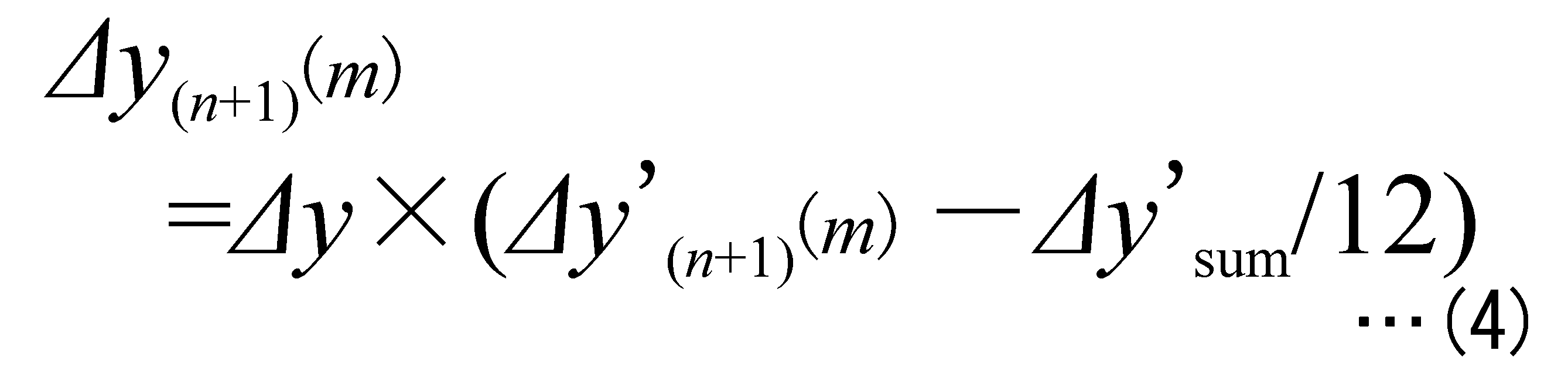
- the normalized torque pattern adjustment unit 26 calculates the normalized pattern change amount (also called the correction amount) ⁇ y(n+1)(0) to ⁇ y(n+1)(11) for the next adjustment iteration n+1 based on the pseudo-random number A using equations (2) to (4) (step S12).
- the normalized pattern change amount also called the correction amount
- the function int is a function that truncates to 1, and the function mod is a remainder function.
- ⁇ y'(n+1)(m) is the amount of change in the provisional coefficient value based on pseudo-random number A before the process of making the sum of each coefficient value zero is performed
- ⁇ y(n+1)(m) is the amount of change in the coefficient value based on pseudo-random number A after the process of making the sum of each coefficient value zero is performed
- ⁇ y is the adjustment range. Note that equation (3) represents the sum of ⁇ y'(n+1)(0) to ⁇ y'(n+1)(11).
- the normalized torque pattern adjustment unit 26 uses equation (5) to calculate a candidate for the normalized torque pattern y(n+1) for the n+1th adjustment based on the amount of change ⁇ y(n+1) (step S13).
- the normalized torque pattern adjustment unit 26 judges whether or not there is a normalized torque pattern coefficient value y(n+1)(m) that exceeds the upper limit or lower limit (greater than the upper limit or smaller than the lower limit) (step S14). If there is a normalized torque pattern coefficient value y(n+1)(m) that exceeds the upper limit or lower limit (step S14: YES), the normalized torque pattern adjustment unit 26 does not use the normalized torque pattern as the adjusted normalized torque pattern, but returns to step S11 and calculates a new pseudo-random number A (step S11).
- step S14 it is possible to set upper and lower limits for the normalized torque pattern, and for example, it is possible to determine a normalized torque pattern with small speed fluctuations within a range in which the maximum value of the torque command (current command) is limited.
- step S14 If there is no normalized torque pattern coefficient value y(n+1)(m) that exceeds the upper or lower limit (step S14: NO), the normalized torque pattern adjustment unit 26 actually controls the motor 2 for a predetermined time using the candidate normalized torque pattern y(n) for the n+1th adjustment round, and calculates the evaluation value J ⁇ m(n+1) (step S15).
- the normalized torque pattern adjustment unit 26 compares the evaluation value J ⁇ m(n+1) with the evaluation value J ⁇ m(n) and determines whether the evaluation value J ⁇ m(n+1) is smaller than the evaluation value J ⁇ m(n) (step S16). If the evaluation value J ⁇ m(n+1) is not smaller than the evaluation value J ⁇ m(n) (step S16: NO), the normalized torque pattern adjustment unit 26 discards the candidate for the normalized torque pattern y(n+1) for the n+1th adjustment (step S17), returns to step S11, and calculates a new pseudo-random number A (step S11).
- step S16 If the evaluation value J ⁇ m(n+1) is smaller than the evaluation value J ⁇ m(n) (step S16: YES), the normalized torque pattern adjustment unit 26 adopts the candidate for the normalized torque pattern y(n+1) for the n+1th adjustment as the next standard (step S18), and ends the process shown in FIG. 4.
- Figure 5 shows an example of adjustment of the normalized torque pattern.
- the normalized pattern change amount ⁇ y(n+1) is shown as a dotted line, and the n+1th normalized pattern y(n+1) is shown as a solid line.
- the evaluation value J ⁇ m is calculated based on the deviation ⁇ m, but it may also be a value based on, for example, the estimated fluctuation range of the motor's rotation speed (the difference between the maximum and minimum rotation speeds during one rotation of the motor 2).
- FIG. 6 shows an example of the configuration of the normalized torque pattern table 131a (corresponding to the normalized torque pattern table 131 shown in FIG. 2).
- FIG. 7 shows an example of the relationship between the rotor rotation angle and a plurality of coefficient values (black circles) with the horizontal axis representing the rotor rotation angle [deg] and the vertical axis representing the coefficient value [%].
- the coefficient value (table value) is constant between, for example, 0 and 30 [deg], but in the second embodiment, it is defined as a value of 15 [deg] at the center of the coefficient value (table value), and the value between adjacent coefficient values (table values) is an interpolated value obtained by linear interpolation as shown by the dashed line.
- the interpolated value is a value connecting the center values, so the average value does not change. That is, it is a normalized pattern.
- FIG. 8 shows a configuration example of the control device 1a according to the third embodiment of the present disclosure.
- the control device 1a according to the third embodiment further changes the adjustment value ⁇ es of the rotational position as one of the parameters of the normalized torque pattern.
- the control device 1a shown in FIG. 8 is different from the control device 1 shown in FIG. 1 in the configuration of the normalized torque pattern adjustment unit 26a shown in FIG. 8 corresponding to the normalized torque pattern adjustment unit 26 shown in FIG. 1, and is newly equipped with an adder 27.
- the adder 27 adds the rotational position ⁇ es output by the speed/position estimation unit 11 and the ⁇ es output by the normalized torque pattern adjustment unit 26a, and inputs the addition result to the load torque compensation unit 13 in place of the rotational position ⁇ es in the first embodiment.
- the normalized torque pattern adjustment unit 26a has a function of changing and outputting the adjustment value ⁇ es while monitoring the evaluation value J ⁇ m.
- the current control can be delayed with respect to the torque command (current command), so that the delay of the output torque can be compensated.
- the normalized torque pattern adjustment unit 26 shown in FIG. 1 adjusts the multiple coefficient values individually using one of multiple bit patterns, each of which has a bit number based on the number of multiple coefficient values that make up the normalized torque pattern
- the bit pattern is generated by sequentially combining a first number of consecutive "1"s and a second number of consecutive "0"s.
- the control device 1b shown in Fig. 9 differs from the control device 1 according to the first embodiment described with reference to Fig. 1 etc. in the following respects. That is, the control device 1b shown in Fig. 9 differs from the control device 1 shown in Fig. 1 in a part of the configuration of a speed control unit 20b corresponding to the speed control unit 20 shown in Fig. 1. Also, the operation of a normalized torque pattern adjustment unit 26b corresponding to the normalized torque pattern adjustment unit 26 shown in Fig. 1 is partially different.
- the maximum values (upper and lower limits) (step S14 in FIG. 4) set for the normalized torque pattern coefficient values y(n)(m) in the first embodiment are calculated based on the average torque command value, which is the output of the speed PI control unit 12.
- the output of the speed PI control unit 12 is represented as the average torque command value pre_ ⁇ _cmd.
- the input to the current conversion unit 16 is represented as the output torque command value ⁇ _cmd.
- the output of the load torque compensation unit 13 is represented as the compensation torque value ⁇ _cmp.
- the maximum value of the output torque command value ⁇ _cmd obtained from a value having a predetermined margin from the maximum value of the instantaneous current that can be passed through the switching element (hereinafter referred to as "element") of the inverter 4 based on the current capacity of the element is set to the maximum output torque command value ⁇ _max.
- the maximum value y_max of the normalized torque pattern coefficient value y(n)(m) can be calculated from the average torque command value pre_ ⁇ _cmd and the maximum output torque command value ⁇ _max using the following formula (6):
- the normalized torque pattern coefficient value y(n)(m) can be limited based on the current limit value of the elements of the inverter 4, thereby preventing the need to increase the current capacity of the elements, for example.
- the load torque compensation unit 13 calculates a compensation torque value ⁇ _cmp by multiplying the average torque command value pre_ ⁇ _cmd, which is the output of the speed PI control unit 12, by the value of the normalized torque pattern table 131. Then, the adder 15 adds this compensation torque value ⁇ _cmp to the average torque command value pre_ ⁇ _cmd to determine the torque command value ⁇ _cmd to be input to the current change unit 16.
- a limiter 29 is provided at the output of the adder 15 to limit the torque command value ⁇ _cmd to the maximum output torque command value ⁇ _max.
- the limiter 29 receives the output of the adder 15, limits the upper limit of the output torque command value ⁇ _cmd to + ⁇ _max, limits the lower limit to - ⁇ _max, and outputs the result to the current converter 16.
- ⁇ _max is the maximum value of the output torque command that is set according to the maximum rated current of the switching element of the inverter 4, etc.
- the speed control unit 20b of the fifth embodiment is newly equipped with a zero-order holder 28.
- the zero-order holder 28 inputs the average torque command value pre_ ⁇ _cmd output by the speed PI control unit 12, and performs sample-holding at each comparison timing so that the same average torque command value pre_ ⁇ _cmd is used to calculate the compensation torque value ⁇ _cmp in the load torque compensation unit 13 while the normalized torque pattern adjustment unit 26b compares the speed fluctuation due to the current normalized torque pattern y(n) with the speed fluctuation due to the candidate for the next normalized torque pattern y(n+1), and outputs the same value to the load torque compensation unit 13. Furthermore, when the speed fluctuation is not compared, the zero-order holder 28 outputs the average torque command value pre_ ⁇ _cmd output by the speed PI control unit 12 directly to the load torque compensation unit 13.
- the average torque command value pre_ ⁇ _cmd is set to the same value while comparing the speed fluctuation with the normalized torque pattern, so that the speed fluctuation can be compared using the same y_max.
- the speed control unit 20b according to the fifth embodiment differs in that it is newly equipped with a zero-order holder 28 and a limiter 29, but the other configurations and operations are the same as those of the speed control unit 20 shown in FIG. 1.
- the normalized torque pattern adjustment unit 26b starts the process shown in FIG. 10 when a predetermined condition is satisfied.
- the normalized torque pattern adjustment unit 26b adjusts each coefficient value y(n)(m) of the normalized torque pattern y(n) set in the normalization pattern table 131 to generate a candidate for the next normalized torque pattern y(n+1), evaluates the normalized torque pattern y(n+1) based on a predetermined evaluation value related to the fluctuation of the rotation speed, and determines whether to adopt the normalized torque pattern y(n+1) or to adopt the normalized torque pattern y(n) as is.
- the predetermined condition when the process shown in FIG.
- the number of divisions in the normalized torque pattern table 131 is assumed to be 12, as shown in Figures 2 and 3.
- the normalized torque pattern adjustment unit 26b causes the zero-order holder 28 to hold the average torque command value pre_ ⁇ _cmd (step S20).
- the normalized torque pattern adjustment unit 26b actually controls the motor 2 for a predetermined time using the normalized torque pattern y(n) before adjustment, which has been adjusted the nth time and is currently being used as a reference, and calculates, for example, the evaluation value J ⁇ m(n) of equation (1) (step S21).
- the normalized torque pattern adjustment unit 26b calculates a pseudo-random number A, which is a bit pattern having a number of bits based on the number of coefficient values that make up the normalized torque pattern (12 in the example shown in Figures 2 and 3) (step S22).
- the normalized torque pattern adjustment unit 26b calculates the maximum value y_max of each coefficient value y'(n+1)(m) based on the average torque command value pre_ ⁇ _cmd using equation (6) (step S25).
- formula (8) is a formula obtained by inverting the sign of the right-hand side of formula (2).
- the normalized torque pattern adjustment unit 26b uses equations (3) to (5) to calculate a candidate for the normalized torque pattern y(n+1) for the n+1th adjustment based on the amount of change ⁇ y(n+1) (step S27).
- the normalized pattern y(n+1) is calculated from this normalized pattern amount of change ⁇ y(n+1) using equation (5), the value of the normalized pattern can be kept within the range of -ymax to +ymax.
- the normalized torque pattern adjustment unit 26b actually controls the motor 2 for a predetermined time using the candidate normalized torque pattern y(n) for the n+1th adjustment round, and calculates the evaluation value J ⁇ m(n+1) (step S28).
- the normalized torque pattern adjustment unit 26b compares the evaluation value J ⁇ m(n+1) with the evaluation value J ⁇ m(n) and determines whether the evaluation value J ⁇ m(n+1) is smaller than the evaluation value J ⁇ m(n) (step S29). On the other hand, if the evaluation value J ⁇ m(n+1) is not smaller than the evaluation value J ⁇ m(n) (step S29: NO), the normalized torque pattern adjustment unit 26b discards the candidate for the normalized torque pattern y(n+1) after the nth adjustment and adopts the normalized torque pattern y(n) after the nth adjustment as the next standard (step S30).
- step S29 YES
- the normalized torque pattern adjustment unit 26b adopts the candidate for the normalized torque pattern y(n+1) after the nth adjustment as the next standard (step S31).
- step S30 or step S31 the normalized torque pattern adjustment unit 26b releases the hold of the average torque command value pre_ ⁇ _cmd in the zero-order holder 28 (step S32) and ends the process shown in FIG. 10.
- the normalized torque pattern is not limited based on the maximum output torque command value ⁇ _max, for example, when the average torque command value pre_ ⁇ _cmd is relatively large, the output torque command value ⁇ _cmd becomes larger than the maximum output torque command value ⁇ _max, compensation according to the compensation torque value ⁇ _cmp is not performed, and even if the normalized torque pattern is changed for adjustment, it is not reflected in the speed fluctuation. In this case, it is considered that the normalized torque pattern cannot be adjusted.
- the change amount ⁇ y is limited based on the average torque command value pre_ ⁇ _cmd and the maximum value ⁇ _max, so that it is possible to compare before and after changing the normalized torque pattern based on the speed fluctuation.
- the coefficient value y(n+1)(m) of the normalized torque pattern is adjusted to fall within the range of the maximum coefficient value y_max based on the average torque command value pre_ ⁇ _cmd (average output torque command value) and the maximum value ⁇ _max of the output torque command value ⁇ _cmd corresponding to the elements possessed by the inverter 4.
- the control device 1b of this embodiment calculates the evaluation value J ⁇ m(n) using the normalized torque pattern y(n) before adjustment and the evaluation value J ⁇ m(n+1) using the normalized torque pattern y(n+1) after adjustment using the same average torque command value pre_ ⁇ _cmd (average output torque command value).
- a normalized torque pattern before adjustment and a normalized torque pattern after adjustment which is a normalized torque pattern in which multiple coefficient values are individually adjusted using one of multiple bit patterns each having a bit number based on the number of multiple coefficient values constituting the normalized torque pattern, are compared based on each calculation result of a predetermined evaluation value related to the fluctuation of the rotation speed obtained as a result of actually using the normalized torque pattern to control a motor, and one of the normalized torque patterns is adopted. Therefore, the normalized torque pattern can be appropriately adjusted.
- the rotation position, rotation speed, etc. are estimated based on the current value, etc., without detecting the rotation position, rotation speed, etc. using a sensor.
- the current value is not limited to detecting the AC current using a sensor, and the AC current may be estimated by detecting the DC current input to the inverter circuit, for example.
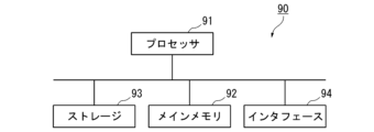
- FIG. 11 is a schematic block diagram illustrating a configuration of a computer according to at least one embodiment.
- the computer 90 comprises a processor 91 , a main memory 92 , a storage 93 , and an interface 94 .
- the above-mentioned control devices 1, 1a, and 1b are implemented in a computer 90.
- the operations of the above-mentioned processing units are stored in the form of a program in a storage 93.
- the processor 91 reads the program from the storage 93, loads it in the main memory 92, and executes the above-mentioned processing in accordance with the program.
- the processor 91 also secures storage areas in the main memory 92 corresponding to the above-mentioned storage units in accordance with the program.
- the program may be for realizing some of the functions to be performed by the computer 90.
- the program may be for realizing functions by combining with other programs already stored in storage, or in combination with other programs implemented in other devices.
- the computer may include a custom LSI (Large Scale Integrated Circuit) such as a PLD (Programmable Logic Device) in addition to or instead of the above configuration.
- PLDs include PAL (Programmable Array Logic), GAL (Generic Array Logic), CPLD (Complex Programmable Logic Device), FPGA (Field Programmable Gate Array), etc.
- PLDs Programmable Logic Device
- PAL Programmable Array Logic
- GAL Generic Array Logic
- CPLD Complex Programmable Logic Device
- FPGA Field Programmable Gate Array
- storage 93 examples include HDD (Hard Disk Drive), SSD (Solid State Drive), magnetic disk, magneto-optical disk, CD-ROM (Compact Disc Read Only Memory), DVD-ROM (Digital Versatile Disc Read Only Memory), semiconductor memory, etc.
- Storage 93 may be internal media directly connected to the bus of computer 90, or may be external media connected to computer 90 via interface 94 or a communication line.
- computer 90 that receives the program may expand the program into main memory 92 and execute the above-mentioned processing.
- storage 93 is a non-transitory tangible storage medium.
- control devices 1, 1a, and 1b described in each embodiment can be understood, for example, as follows.
- the control devices 1, 1a, and 1b are control devices 1, 1a, and 1b that control the rotation speed of the motor 2 by controlling an inverter 4 that AC drives the motor 2 that rotates the compressor 5, and calculate a compensation torque value ( ⁇ _cmp) by multiplying an average output torque command value (average torque command value pre_ ⁇ _cmd) calculated according to the deviation ⁇ m between the rotation speed ⁇ mes of the motor 2 and the rotation speed command value ⁇ m* by a normalized torque pattern y(n), which is a pattern of multiple coefficient values y(n)(m) that change according to the rotation angle ⁇ es of the motor 2 that is set so that the total value for one rotation is zero, and multiplying the average output torque command value by the compensation torque value ( ⁇ _cmp).
- the control device controls the inverter 4 by setting an output torque command value ( ⁇ _cmd) of the motor 2 according to the rotation angle ⁇ es by adding a torque value, and compares the normalized torque pattern y(n) before adjustment with a normalized torque pattern after adjustment y(n+1) in which the multiple coefficient values are individually adjusted using one of multiple bit patterns each having a bit number based on the number of the multiple coefficient values y(n)(m) based on each calculation result of a predetermined evaluation value J ⁇ m related to the fluctuation of the rotation speed ⁇ m obtained as a result of actually using the normalized torque pattern y(n) to control the motor 2, and adopts one of the normalized torque patterns.
- the normalized torque pattern can be appropriately adjusted.
- control devices 1, 1a, and 1b according to the second aspect are the control devices 1, 1a, and 1b according to (1), in which the multiple bit patterns are pseudo-random number sequences. According to this aspect, it is not necessary to prepare multiple patterns for adjustment in advance.
- control devices 1, 1a, and 1b according to a third aspect are the control devices 1, 1a, and 1b according to (1) or (2), wherein the evaluation value is a value obtained by removing a predetermined high-frequency component from the squared value ⁇ m2 of the time series value of the deviation or the time series value ⁇ m of the deviation.
- the control devices 1 and 1a according to the fourth aspect are the control devices 1 and 1a according to (1) to (3), in which upper and lower limit values are set for the coefficient values, and if any of the multiple coefficient values exceeds the upper limit value or the lower limit value, the normalized torque pattern is not set as the adjusted normalized torque pattern.
- the control devices 1, 1a, and 1b according to the fifth aspect are the control devices 1, 1a, and 1b of (1) to (4), and further change the estimated value ⁇ es of the rotation angle of the motor when actually controlling the motor using the adjusted normalized torque pattern to calculate the evaluation value.
- the control devices 1, 1a, and 1b according to the sixth aspect are the control devices 1, 1a, and 1b according to (1), (3) to (5), in which the bit pattern is generated by sequentially combining a first number of consecutive "1"s and a second number of consecutive "0"s.
- the control device 1b according to the seventh aspect is the control device 1b according to (1), (2), (3), (5) and (6), in which the coefficient value is adjusted to fall within a maximum value range of the coefficient value based on the average output torque command value and the maximum value of the output torque command value corresponding to the elements possessed by the inverter.
- the control device 1b according to the eighth aspect is the control device 1b according to (1) to (7), in which the calculation of the evaluation value using the normalized torque pattern before the adjustment and the calculation of the evaluation value using the normalized torque pattern after the adjustment are performed using the same average output torque command value.
- the normalized torque pattern can be appropriately adjusted.
Landscapes
- Engineering & Computer Science (AREA)
- Mechanical Engineering (AREA)
- General Engineering & Computer Science (AREA)
- Physics & Mathematics (AREA)
- Thermal Sciences (AREA)
- Power Engineering (AREA)
- Chemical & Material Sciences (AREA)
- Combustion & Propulsion (AREA)
- Control Of Ac Motors In General (AREA)
Abstract
制御装置は、圧縮機を回転駆動するモータを交流駆動するインバータを制御することでモータの回転数を制御する制御装置であって、モータの回転数と回転数指令値との偏差に応じて算出した平均出力トルク指令値に、1回転の合計値がゼロとなるように設定されたモータの回転角に応じて変化する複数の係数値のパターンである正規化トルクパターン、を乗じることで補償トルク値を算出し、平均出力トルク指令値に補償トルク値を加算することで回転角に応じてモータの出力トルク指令値を設定してインバータを制御するとともに、調整前の正規化トルクパターンと、複数の係数値の個数に基づくビット数をそれぞれ有する複数のビットパターンのいずれかを用いて複数の係数値を個々に調整した正規化トルクパターンである調整後正規化トルクパターンとを、実際に用いてモータを制御した結果得られた回転数の変動に係る所定の評価値の各算出結果に基づいて比較し、いずれか一方の正規化トルクパターンを採用する。
Description
本開示は、制御装置、制御方法および空気調和機に関する。本願は、2022年10月21日に、日本に出願された特願2022-169319号に基づき優先権を主張し、その内容をここに援用する。
ロータリ圧縮機においては、1回転の間に吸入、圧縮、および吐出の各行程における冷媒ガス圧の変化が発生するため、定常的な負荷トルク変動が発生する。そこで、特許文献1に記載されている制御装置は、平均トルクと正規化トルクパターンとの積により、推定回転子位置に合わせて出力トルク指令を補償することで、モータの速度変動を抑えている。特許文献1に記載されている正規化トルクパターンは、例えばモータのロータの回転角度30度毎に設定された係数値のパターンであり、平均トルクと各区間の係数値との積が全区間の合計では平均トルクに一致するように、各区間の係数値が正規化されている。また、この制御装置では、予め用意した複数の変調率から選択した1つの変調率を正規化トルクパターンに乗じることで、正規化トルクパターンが調整される。この変調率は、モータの回転角度の全域あるいは一部の区間に適用される。また、変調率の選択は、変調率を設定した結果、推定回転数変動幅が増加したか減少したかを判定しながら、推定回転数変動幅が所定値以下あるいは最小値となるように、複数段階に設定された変調率を増減させることで行われる。特許文献1に記載されている制御装置によれば、例えば圧力変動等によって圧縮機の負荷トルクの波形が変化した場合でも、モータ出力トルクを負荷トルクに対して適切にマッチングさせることができる。なお、特許文献1には、正規化トルクパターンのある部分だけの増減もパターンの変更も可能としてもよい、との記述はあるが、具体的な構成についての言及はなかった。
本開示は、上記事情に鑑みてなされたものであり、適切に正規化トルクパターンを調整することができる制御装置、制御方法および空気調和機を提供することを目的とする。
適切に正規化トルクパターンを調整することができるようにするため、本開示に係る制御装置は、圧縮機を回転駆動するモータを交流駆動するインバータを制御することで前記モータの回転数を制御する制御装置であって、前記モータの回転数と回転数指令値との偏差に応じて算出した平均出力トルク指令値に、1回転の合計値がゼロとなるように設定された前記モータの回転角に応じて変化する複数の係数値のパターンである正規化トルクパターン、を乗じることで補償トルク値を算出し、前記平均出力トルク指令値に前記補償トルク値を加算することで前記回転角に応じて前記モータの出力トルク指令値を設定して前記インバータを制御するとともに、調整前の前記正規化トルクパターンと、前記複数の係数値の個数に基づくビット数をそれぞれ有する複数のビットパターンのいずれかを用いて前記複数の係数値を個々に調整した前記正規化トルクパターンである調整後正規化トルクパターンとを、実際に用いて前記モータを制御した結果得られた前記回転数の変動に係る所定の評価値の各算出結果に基づいて比較し、いずれか一方の前記正規化トルクパターンを採用する。
本開示に係る制御方法は、圧縮機を回転駆動するモータを交流駆動するインバータを制御することで前記モータの回転数を制御する制御方法であって、前記モータの回転数と回転数指令値との偏差に応じて算出した平均出力トルク指令値に、1回転の合計値がゼロとなるように設定された前記モータの回転角に応じて変化する複数の係数値のパターンである正規化トルクパターン、を乗じることで補償トルク値を算出し、前記平均出力トルク指令値に前記補償トルク値を加算することで前記回転角に応じて前記モータの出力トルク指令値を設定して前記インバータを制御するとともに、調整前の前記正規化トルクパターンと、前記複数の係数値の個数に基づくビット数をそれぞれ有する複数のビットパターンのいずれかを用いて前記複数の係数値を個々に調整した前記正規化トルクパターンである調整後正規化トルクパターンとを、実際に用いて前記モータを制御した結果得られた前記回転数の変動に係る所定の評価値の各算出結果に基づいて比較し、いずれか一方の前記正規化トルクパターンを採用する。
本開示に係る空気調和機は、圧縮機と、前記圧縮機を回転駆動するモータと、前記モータを交流駆動するインバータと、前記インバータを制御することで前記モータの回転数を制御する制御装置であって、前記モータの回転数と回転数指令値との偏差に応じて算出した平均出力トルク指令値に、1回転の合計値がゼロとなるように設定された前記モータの回転角に応じて変化する複数の係数値のパターンである正規化トルクパターン、を乗じることで補償トルク値を算出し、前記平均出力トルク指令値に前記補償トルク値を加算することで前記回転角に応じて前記モータの出力トルク指令値を設定して前記インバータを制御するとともに、調整前の前記正規化トルクパターンと、前記複数の係数値の個数に基づくビット数をそれぞれ有する複数のビットパターンのいずれかを用いて前記複数の係数値を個々に調整した前記正規化トルクパターンである調整後正規化トルクパターンとを、実際に用いて前記モータを制御した結果得られた前記回転数の変動に係る所定の評価値の各算出結果に基づいて比較し、いずれか一方の前記正規化トルクパターンを採用する制御装置とを備える。
本開示の制御装置、制御方法および空気調和機によれば、適切に正規化トルクパターンを調整することができる。
以下、本開示の実施形態に係る制御装置、制御方法および空気調和機について、図1~図11を参照して説明する。図1は、本開示の第1実施形態に係る空調回転圧縮機に接続されたモータの制御装置の構成例を示すブロック図である。図2および図3は、本開示の第1実施形態に係る正規化トルクパターンテーブルの構成例を示す模式図である。図4は、本開示の第1実施形態に係る制御装置の動作例を示すフローチャートである。図5は、本開示の第1実施形態に係る制御装置の動作例を示す模式図である。図6および図7は、本開示の第2実施形態に係る正規化トルクパターンテーブルの構成例を示す模式図である。図8は、本開示の第3実施形態に係る空調回転圧縮機に接続されたモータの制御装置の構成例を示すブロック図である。図9は、本開示の第5実施形態に係る空調回転圧縮機に接続されたモータの制御装置の構成例を示すブロック図である。図10は、本開示の第5実施形態に係る制御装置の動作例を示すフローチャートである。図11は、少なくとも1つの実施形態に係るコンピュータの構成を示す概略ブロック図である。なお、各図において同一または対応する構成には同一の符号を用いて説明を適宜省略する。
<第1実施形態>
図1は、本開示の第1実施形態に係る制御装置1の構成例を示す。制御装置1は、空気調和機100が備える圧縮機5を回転駆動するモータ2を交流駆動するインバータ4を制御することでモータ2の回転数(=回転速度)を制御する制御装置である。インバータ4は、交流電源3を電源として、モータ2へ電力を供給する。電流センサ10は、インバータ4からモータ2に通電される電流値を検出する。図1に示す例では、空気調和機100は、制御装置1、モータ2、インバータ4、および、電流センサ10を備える。制御装置1は、例えばマイクロコントローラ等のコンピュータと、そのコンピュータの周辺装置、周辺回路等とを備える。そして、制御装置1は、コンピュータ等のハードウェアと、そのコンピュータが実行するプログラム等のソフトウェアとの組み合わせ等から構成される機能的構成として、減算部14、速度制御部20、負荷トルク補償部13、正規化トルクパターン調整部26、速度・位置推定部11、2相/3相変換部21、および3相/2相変換部22を備える。速度制御部20は、速度PI制御部(速度比例積分(Proportional Integral)制御部)12と、加算部15と、電流変換部16と、減算部17と、電流PI制御部18とを備える。
図1は、本開示の第1実施形態に係る制御装置1の構成例を示す。制御装置1は、空気調和機100が備える圧縮機5を回転駆動するモータ2を交流駆動するインバータ4を制御することでモータ2の回転数(=回転速度)を制御する制御装置である。インバータ4は、交流電源3を電源として、モータ2へ電力を供給する。電流センサ10は、インバータ4からモータ2に通電される電流値を検出する。図1に示す例では、空気調和機100は、制御装置1、モータ2、インバータ4、および、電流センサ10を備える。制御装置1は、例えばマイクロコントローラ等のコンピュータと、そのコンピュータの周辺装置、周辺回路等とを備える。そして、制御装置1は、コンピュータ等のハードウェアと、そのコンピュータが実行するプログラム等のソフトウェアとの組み合わせ等から構成される機能的構成として、減算部14、速度制御部20、負荷トルク補償部13、正規化トルクパターン調整部26、速度・位置推定部11、2相/3相変換部21、および3相/2相変換部22を備える。速度制御部20は、速度PI制御部(速度比例積分(Proportional Integral)制御部)12と、加算部15と、電流変換部16と、減算部17と、電流PI制御部18とを備える。
なお、本実施形態に係る制御装置は、図1に示す例に限定されず、例えばロータリ圧縮機等の圧縮機を駆動するモータを制御する制御装置であればよい。また、圧縮機は空気調和機が備えるものに限定されない。なお、図1は、制御装置1によるモータ2の回転数制御に係る主な構成を示したものであり、例えば、冷媒回路、ファン、温度制御や湿度制御に係る構成等、空気調和機100または制御装置1内の他の一部の構成については図示を省略している。
(制御装置の構成)
3相/2相変換部22は、電流センサ10が検出した3相電流値Iと速度・位置推定部11が推定したモータ2のロータの回転位置(回転角度)θesとを入力し、電流センサ10が検出した3相電流値Iをd軸およびq軸の2相のd軸電流値idおよびq軸電流値iqに変換して出力する。2相/3相変換部21は、回転位置θesと電流PI制御部18が出力したd軸およびq軸の2相のd軸指令電圧値vd*およびq軸指令電圧値vq*とを入力し、3相電圧値Vに変換してインバータ4へ出力する。なお、インバータ4は、2相/3相変換部21が出力した3相電圧値Vに基づいてインバータが備える図示してない複数のスイッチング素子を制御する。
3相/2相変換部22は、電流センサ10が検出した3相電流値Iと速度・位置推定部11が推定したモータ2のロータの回転位置(回転角度)θesとを入力し、電流センサ10が検出した3相電流値Iをd軸およびq軸の2相のd軸電流値idおよびq軸電流値iqに変換して出力する。2相/3相変換部21は、回転位置θesと電流PI制御部18が出力したd軸およびq軸の2相のd軸指令電圧値vd*およびq軸指令電圧値vq*とを入力し、3相電圧値Vに変換してインバータ4へ出力する。なお、インバータ4は、2相/3相変換部21が出力した3相電圧値Vに基づいてインバータが備える図示してない複数のスイッチング素子を制御する。
速度・位置推定部11は、電流PI制御部18が出力した2相のd軸電圧値vdおよびq軸電圧値vqと3相/2相変換部22が出力した2相のd軸電流値idおよびq軸電流値iqに基づきモータ2のロータの回転位置θesと回転数ωmesとを推定する。
減算部14は、回転数指令値ωm*から回転数ωmesを減算し、偏差Δωmを算出して、速度PI制御部12と正規化トルクパターン調整部26へ出力する。
速度PI制御部12は、偏差Δωmに対して比例積分動作によって偏差Δωmを小さくするためのモータ2の出力トルク指令値の平均値である平均トルク指令値を算出して加算部15と負荷トルク補償部13へ出力する。この場合、速度PI制御部12は、モータ2の回転数ωmesと回転数指令値ωm*との偏差Δωmに応じて平均出力トルク指令値を算出して出力する。
負荷トルク補償部13は、正規化トルクパターンテーブル131を含み、速度PI制御部12が出力した平均トルク指令値と、速度・位置推定部11が出力した回転位置θesとを入力し、正規化トルクパターンテーブル131を用いて、補償トルク値を算出して、加算部15へ出力する。補償トルク値は、モータ2の1回転中のモータ2の負荷トルクの変動を補償するためのトルク値である。
正規化トルクパターンテーブル131は、モータ2の回転位置(回転角)θesに応じて変化する複数の係数値のパターンである正規化トルクパターンを定義するテーブルである。負荷トルク補償部13は、正規化トルクパターンテーブル131に基づきモータ2の回転位置(回転角)θesに応じて係数値を決定し、平均トルク指令値に決定した係数値を乗じることで補償トルク値を算出する。補償トルク値と係数値は、正負またはゼロの値をとる。この場合、負荷トルク補償部13は、(各回転位置における補償トルク値=平均トルク指令値×各回転位置における正規化トルクパターン)の式で各回転位置における補償トルク値を算出する。この補償トルク値を平均トルク指令値に加算することで、回転位置θesに応じて負荷トルクの変動分が補償された出力トルク指令値(加算部15の出力値)が算出される。なお、補償トルク値は、1回転中の負荷トルク変動を補償する値であり、補償トルク値によって補償された1回転の出力トルク指令値の平均値は、平均トルク指令値に一致することが求められる。すなわち、補償トルク値の1回転の合計値はゼロであることが求められる。この場合、正規化トルクパターンを構成する(定義する)係数値の1回転の合計値もゼロであることが求められる。図2は、正規化トルクパターンテーブル131の構成例を示す。また、図3は、横軸をロータ回転角度[deg]、縦軸を係数値[%]として、ロータ回転角度と複数の係数値との関係の一例を示す。
図2に示す例では、正規化トルクパターンテーブル131は、1回転360度(deg)を30度毎に区分して12の区間に分け、区間毎に係数値y(n)(m)を設定している。ここで、nは正規化トルクパターンテーブル131の調整回数を表す。また、mは区間の番号(m=0~11)を表す。各係数値y(n)(m)からなるパターンは、正規化トルクパターンy(n)という。上述したように、係数値y(n)(m)は、1回転の合計値がゼロとなるように設定されている。
なお、正規化トルクパターンテーブル131における回転位置の分割数、すなわち位相軸の分割数は次のように決定することができる。すなわち、圧縮機5の負荷トルク変動のk次成分までの低減に対応するには、正規化トルクパターンの位相軸を2×lcm(1,…,k)×ndivまで分割することになる。2はサンプリング定理に基づく係数を表す。lcm(1,…,k)は1からkまでの自然数の最小公倍数を表す。ndivは任意の自然数である。これにより、k次まで高調波を含むトルク変動を表現できる。例えば、1次~3次成分までを低減する場合、ndivを1としたとき、分割数は2×6×1で12分割となる。
加算部15は、速度PI制御部12が出力した平均トルク指令値と、負荷トルク補償部13が出力した補償トルク値を加算して、出力トルク指令値を算出し、電流変換部16へ出力する。
電流変換部16は、加算部15が出力した出力トルク指令値を入力し、出力トルク指令値を電流変換して、d軸指令電流値id*およびq軸指令電流値iq*を算出して減算部17へ出力する。
減算部17は、d軸指令電流値id*およびq軸指令電流値iq*とd軸電流値idおよびq軸電流値iqを入力し、d軸指令電流値id*およびq軸指令電流値iq*からd軸電流値idおよびq軸電流値iqをそれぞれ減算し、指令値とモータ電流値とのd軸成分およびq軸成分の各偏差を算出して、電流PI制御部18へ出力する。
電流PI制御部18は、減算部17が出力した各偏差に対して比例積分動作によって各偏差を小さくするためのd軸指令電圧値vd*とq軸指令電圧値vq*を算出して、2相/3相変換部21と速度・位置推定部11へ出力する。
次に、図4等を参照して正規化トルクパターン調整部26について説明する。本実施形態において、正規化トルクパターン調整部26は、現在基準として使用している調整前の正規化トルクパターンと、正規化トルクパターンを構成する複数の係数値の個数(図2および図3に示す例では分割数12)に基づくビット数をそれぞれ有する複数のビットパターンのいずれかを用いて複数の係数値を個々に調整した正規化トルクパターンである調整後正規化トルクパターンとを、実際に用いてモータ2を制御した結果得られた回転数の変動に係る所定の評価値の各算出結果に基づいて比較し、いずれか一方の正規化トルクパターンを次の正規化トルクパターンとして採用する。なお、本実施形態では、複数のビットパターンは、擬似乱数列である。
(正規化トルクパターン調整部の動作例)
図4は、正規化トルクパターン調整部26の動作例を示す。正規化トルクパターン調整部26は、所定の条件が満たされた場合に、図4に示す処理を開始し、正規化パターンテーブル131に設定されている正規化トルクパターンy(n)の各係数値y(n)(m)を調整して次の正規化トルクパターンy(n+1)を生成し、正規化トルクパターンy(n+1)を回転数の変動に係る所定の評価値に基づいて評価して、正規化トルクパターンy(n+1)を採用するか、正規化トルクパターンy(n)をそのまま採用するかを決定する。なお、図4に示す処理が開始される場合の所定の条件は、例えば、一定の時間であったり、評価値が所定の閾値以上(評価値が小さいほど変動幅が小さい場合)となったりした場合である。また、正規化トルクパターンテーブル131の分割数は図2および図3に示す12とする。
図4は、正規化トルクパターン調整部26の動作例を示す。正規化トルクパターン調整部26は、所定の条件が満たされた場合に、図4に示す処理を開始し、正規化パターンテーブル131に設定されている正規化トルクパターンy(n)の各係数値y(n)(m)を調整して次の正規化トルクパターンy(n+1)を生成し、正規化トルクパターンy(n+1)を回転数の変動に係る所定の評価値に基づいて評価して、正規化トルクパターンy(n+1)を採用するか、正規化トルクパターンy(n)をそのまま採用するかを決定する。なお、図4に示す処理が開始される場合の所定の条件は、例えば、一定の時間であったり、評価値が所定の閾値以上(評価値が小さいほど変動幅が小さい場合)となったりした場合である。また、正規化トルクパターンテーブル131の分割数は図2および図3に示す12とする。
図4に示す処理が開始されると、正規化トルクパターン調整部26は、現在基準として使用している調整前の調整回数n回目の正規化トルクパターンy(n)によって実際に所定時間、モータ2を制御し、評価値Jωm(n)を算出する(ステップS10)。評価値Jωm(n)は、速度・位置推定部11が推定した回転数ωmの変動に係る評価値であり、例えば下式(1)とすることができる。なお、式(1)は調整回数nを指定しない式である。評価値Jωmは、値が小さいほど変動幅が小さいことを示す(良好であることを示す)。評価値Jωmは、本開示に係る「実際に用いてモータを制御した結果得られた回転数の変動に係る所定の評価値」の一例である。

関数LPF(引数)は、「引数」の時系列値に対して所定の高周波成分を除去する処理(ローパスフィルタに掛ける処理)を実行する関数である。高周波成分を除去する処理では、例えば、移動平均法、周波数空間での遮断、ガウス畳込み、一時遅れ系の処理によってローパスフィルタを構成することができる。なお、一時遅れ系でローパスフィルタを構成する場合、ローパスフィルタの時定数を回転周期より長く、正規化パターンの変更周期より短く設定する。
評価値Jωmは速度変動の実効値(Route Mean Square)の二乗なので、すべての高調波成分を含んでいる(平方根を取れば実効値となるが大小関係には影響しないため)。速度変動が振動に与える影響は、速度変動を積分したものが位置変動となるので、周波数に反比例する。このため、Δωmに関数LPFを掛けた値を評価値としてもよい。
次に、正規化トルクパターン調整部26は、正規化トルクパターンを構成する複数の係数値の個数(図2および図3に示す例では12個)に基づくビット数を有するビットパターンである擬似乱数Aを算出する(ステップS11)。ステップS11において、正規化トルクパターン調整部26は、正規化トルクパターンテーブル131を12分割している場合、例えば0~4095(=212-1)の整数Aを乱数(例えばM系列のような擬似乱数)で発生させる。
次に、正規化トルクパターン調整部26は、擬似乱数Aに基づき、次の調整回数n+1回目への正規化パターン変化量(補正量ともいう)Δy(n+1)(0)~Δy(n+1)(11)を、式(2)~式(4)を用いて求める(ステップS12)。


関数intは、小数点以下を切捨てる関数、関数modは剰余関数である。mは回転角度の分割区間の番号(m=0~11)、nは調整回数である。Δy’(n+1)(m)は各係数値の合計値をゼロにする処理を行う前の擬似乱数Aに基づく仮の係数値の変化量であり、Δy(n+1)(m)は各係数値の合計値をゼロにする処理を行った後の擬似乱数Aに基づく係数値の変化量であり、Δyは調整幅である。なお、式(3)は、Δy’(n+1)(0)~Δy’(n+1)(11)の和を表す。
次に、正規化トルクパターン調整部26は、式(5)を用いて、変化量Δy(n+1)に基づき調整回数n+1回目の正規化トルクパターンy(n+1)の候補を算出する(ステップS13)。

次に、正規化トルクパターン調整部26は、上限値または下限値を超える(上限値より大きいかまたは下限値より小さい)正規化トルクパターン係数値y(n+1)(m)があるか否かを判定する(ステップS14)。上限値または下限値を超える正規化トルクパターン係数値y(n+1)(m)がある場合(ステップS14:YES)、正規化トルクパターン調整部26は、当該正規化トルクパターンを調整後正規化トルクパターンとせず、ステップS11へ戻り、新たな擬似乱数Aを算出する(ステップS11)。ステップS14の判定処理を設けることで、正規化トルクパターンに上限値および下限値を設定することができ、例えば、トルク指令(電流指令)の最大値を制限した範囲で、速度変動の小さい正規化トルクパターンを決定することができる。
上限値または下限値を超える正規化トルクパターン係数値y(n+1)(m)がない場合(ステップS14:NO)、正規化トルクパターン調整部26は、調整回数n+1回目の正規化トルクパターンy(n)の候補によって実際に所定時間、モータ2を制御し、評価値Jωm(n+1)を算出する(ステップS15)。
次に、正規化トルクパターン調整部26は、評価値Jωm(n+1)と評価値Jωm(n)を比較し、評価値Jωm(n+1)が評価値Jωm(n)より小さいか否かを判定する(ステップS16)。評価値Jωm(n+1)が評価値Jωm(n)より小さくない場合(ステップS16:NO)、正規化トルクパターン調整部26は、調整回数n+1回目の正規化トルクパターンy(n+1)の候補を破棄し(ステップS17)、ステップS11へ戻り、新たな擬似乱数Aを算出する(ステップS11)。評価値Jωm(n+1)が評価値Jωm(n)より小さい場合(ステップS16:YES)、正規化トルクパターン調整部26は、調整回数n+1回目の正規化トルクパターンy(n+1)の候補を次の基準として採用し(ステップS18)、図4に示す処理を終了する。
図5は、正規化トルクパターンの調整例を示す。図5は、図3に示すn回目の正規化パターンy(n)(破線)に対して、例として、擬似乱数A=604、調整幅Δy=30[%]としたときの調整例を示す。正規化パターン変化量Δy(n+1)は鎖線のようになり、n+1回目の正規化パターンy(n+1)は実線となる。
(作用・効果)
本実施形態によれば、速度変動の実効値を求め、速度変動が小さくなるように負荷トルクパターンを調整することができるので、個別の高調波成分を求めることなく、負荷変動の高調波成分を含めて、速度変動を抑えることができる。また、正規化トルクパターンを構成する複数の係数値を乱数に基づいて調整することで、複数の変更パターンを自動的に生成することができ、正規化トルクパターンを柔軟に調整することができる。
本実施形態によれば、速度変動の実効値を求め、速度変動が小さくなるように負荷トルクパターンを調整することができるので、個別の高調波成分を求めることなく、負荷変動の高調波成分を含めて、速度変動を抑えることができる。また、正規化トルクパターンを構成する複数の係数値を乱数に基づいて調整することで、複数の変更パターンを自動的に生成することができ、正規化トルクパターンを柔軟に調整することができる。
(変形例)
なお、上記では評価値Jωmは偏差Δωmに基づいて算出しているが、例えばモータの推定回転数変動幅(モータ2が1回転する間の最大回転数と最小回転数の差)に基づく値としてもよい。
なお、上記では評価値Jωmは偏差Δωmに基づいて算出しているが、例えばモータの推定回転数変動幅(モータ2が1回転する間の最大回転数と最小回転数の差)に基づく値としてもよい。
<第2実施形態>
第2実施形態は、第1実施形態と比較して、正規化トルクパターンテーブル131の構成が異なる。図6は、正規化トルクパターンテーブル131a(図2に示す正規化トルクパターンテーブル131に対応)の構成例を示す。また、図7は、横軸をロータ回転角度[deg]、縦軸を係数値[%]として、ロータ回転角度と複数の係数値(黒丸)との関係の一例を示す。第1実施形態では係数値(テーブル値)は例えば0~30[deg]の間は一定としたが、第2実施形態では係数値(テーブル値)中心の15[deg]の値として定義し、隣接する係数値(テーブル値)の間は破線で示すように線形補間した補間値とする。この場合、補間値は中心値間を接続した値なので平均値は変化しない。すなわち、正規化パターンとなっている。
第2実施形態は、第1実施形態と比較して、正規化トルクパターンテーブル131の構成が異なる。図6は、正規化トルクパターンテーブル131a(図2に示す正規化トルクパターンテーブル131に対応)の構成例を示す。また、図7は、横軸をロータ回転角度[deg]、縦軸を係数値[%]として、ロータ回転角度と複数の係数値(黒丸)との関係の一例を示す。第1実施形態では係数値(テーブル値)は例えば0~30[deg]の間は一定としたが、第2実施形態では係数値(テーブル値)中心の15[deg]の値として定義し、隣接する係数値(テーブル値)の間は破線で示すように線形補間した補間値とする。この場合、補間値は中心値間を接続した値なので平均値は変化しない。すなわち、正規化パターンとなっている。
<第3実施形態>
図8は、本開示の第3実施形態に係る制御装置1aの構成例を示す。第3実施形態の制御装置1aは、正規トルクパターンのパラメータの1つとして、さらに、回転位置の調整値Δθesを変更する。図8に示す制御装置1aは、図1に示す制御装置1と比較して、図1に示す正規化トルクパターン調整部26に対応する図8に示す正規化トルクパターン調整部26aの構成が一部異なるとともに、新たに加算部27を備えている。加算部27は、速度・位置推定部11が出力した回転位置θesと正規化トルクパターン調整部26aが出力したΔθesとを加算して、加算結果を第1実施形態における回転位置θesに代えて負荷トルク補償部13へ入力する。正規化トルクパターン調整部26aは、正規化トルクパターン調整部26による正規化トルクパターンの調整機能に加え、評価値Jωmを監視しながら調整値Δθesを変化させて出力する機能を有する。第3実施形態によれば、例えば、トルク指令(電流指令)に対して電流制御が遅らせることができるため、出力トルクが遅れることを補償することができる。
図8は、本開示の第3実施形態に係る制御装置1aの構成例を示す。第3実施形態の制御装置1aは、正規トルクパターンのパラメータの1つとして、さらに、回転位置の調整値Δθesを変更する。図8に示す制御装置1aは、図1に示す制御装置1と比較して、図1に示す正規化トルクパターン調整部26に対応する図8に示す正規化トルクパターン調整部26aの構成が一部異なるとともに、新たに加算部27を備えている。加算部27は、速度・位置推定部11が出力した回転位置θesと正規化トルクパターン調整部26aが出力したΔθesとを加算して、加算結果を第1実施形態における回転位置θesに代えて負荷トルク補償部13へ入力する。正規化トルクパターン調整部26aは、正規化トルクパターン調整部26による正規化トルクパターンの調整機能に加え、評価値Jωmを監視しながら調整値Δθesを変化させて出力する機能を有する。第3実施形態によれば、例えば、トルク指令(電流指令)に対して電流制御が遅らせることができるため、出力トルクが遅れることを補償することができる。
<第4実施形態>
第4実施形態は、第1実施形態と比較して、乱数Aにより正規化トルクパターンy(n+1)を決めるかわりに、基本波を調整するΔy’(n+1)のうち6つの値が連続する(A=001111110000,A=000011111100(2進数)など12 通り)のみで調整する。この構成によれば基本波が調整できる。同様に2次成分を調整するΔy’(n+1)のうち3つの値が連続する(A=001110001110,A=110001110001(2進数)など6通り)のみで調整すれば2次成分が調整でき、2つの値が連続する(A=001100110011,A=100110011001(2進数)など4通り)のみで調整すれば3次成分が調整できる。
第4実施形態は、第1実施形態と比較して、乱数Aにより正規化トルクパターンy(n+1)を決めるかわりに、基本波を調整するΔy’(n+1)のうち6つの値が連続する(A=001111110000,A=000011111100(2進数)など12 通り)のみで調整する。この構成によれば基本波が調整できる。同様に2次成分を調整するΔy’(n+1)のうち3つの値が連続する(A=001110001110,A=110001110001(2進数)など6通り)のみで調整すれば2次成分が調整でき、2つの値が連続する(A=001100110011,A=100110011001(2進数)など4通り)のみで調整すれば3次成分が調整できる。
本実施形態においては、図1に示す正規化トルクパターン調整部26が、正規化トルクパターンを構成する複数の係数値の個数に基づくビット数をそれぞれ有する複数のビットパターンのいずれかを用いて複数の係数値を個々に調整する際に、第4実施形態では、ビットパターンを第1のビット数の「1」の連続と第2のビット数の「0」の連続とを順に組み合わせることで生成する。この構成によれば、例えば特定の次数だけを調整することができる。
<第5実施形態>
図9は、本開示の第5実施形態に係る制御装置1bの構成例を示す。図9に示す制御装置1bは、図1等を参照して説明した第1実施形態に係る制御装置1に対して、次の点が異なる。すなわち、図9に示す制御装置1bは、図1に示す制御装置1に対して、図1に示す速度制御部20に対応する速度制御部20bの構成の一部が異なる。また、図1に示す正規化トルクパターン調整部26に対応する正規化トルクパターン調整部26bの動作の一部が異なる。
図9は、本開示の第5実施形態に係る制御装置1bの構成例を示す。図9に示す制御装置1bは、図1等を参照して説明した第1実施形態に係る制御装置1に対して、次の点が異なる。すなわち、図9に示す制御装置1bは、図1に示す制御装置1に対して、図1に示す速度制御部20に対応する速度制御部20bの構成の一部が異なる。また、図1に示す正規化トルクパターン調整部26に対応する正規化トルクパターン調整部26bの動作の一部が異なる。
第5実施形態では、第1実施形態で正規化トルクパターン係数値y(n)(m)に対して設定した最大値(上限値と下限値)(図4のステップS14)を、速度PI制御部12の出力である平均トルク指令値に基づいて算出する。なお、図9では、速度PI制御部12の出力を平均トルク指令値pre_τ_cmdと表記する。また、電流変換部16の入力を出力トルク指令値τ_cmdと表記する。また、負荷トルク補償部13の出力を補償トルク値τ_cmpと表記する。また、第5実施形態では、インバータ4のスイッチング素子(以下、「素子」という)の電流容量から素子に流せる瞬時電流の最大値から所定のマージンを持った値から得られる出力トルク指令値τ_cmdの最大値を、出力トルク指令最大値τ_maxとする。この場合、正規化トルクパターン係数値y(n)(m)の最大値y_maxは、平均トルク指令値pre_τ_cmdと出力トルク指令最大値τ_maxとから下式(6)で算出することができる。

正規化トルクパターンy(n)の調整を行う際に、インバータ4の素子の電流制限値に基づいて正規化トルクパターン係数値y(n)(m)に制限を行うことで、例えば素子の電流容量を増加させる必要が生じることを防ぐことができる。
なお、第5実施形態でも、第1実施形態と同様、負荷トルクの変動を補償するため、負荷トルク補償部13が、速度PI制御部12の出力である平均トルク指令値pre_τ_cmdに対して、正規化トルクパターンテーブル131の値を掛け合わせることで補償トルク値τ_cmpを算出する。そして、加算部15によってこの補償トルク値τ_cmpを平均トルク指令値pre_τ_cmdに加えることで、電流変化部16へ入力するトルク指令値τ_cmdを求めている。第5実施形態では、この加算部15の出力にリミッタ29を設けることで、トルク指令値τ_cmdを、出力トルク指令最大値τ_maxに制限している。
リミッタ29は、加算部15の出力を入力し、出力トルク指令値τ_cmdの上限値を+τ_maxで制限するとともに、下限値を-τ_maxで制限して、電流変換部16へ出力する。τ_maxは、上述したように、インバータ4が備えるスイッチング素子の最大定格電流等に応じて設定される出力トルク指令の最大値である。
また、第5実施形態では、現在基準として用いている正規化トルクパターンy(n)と、次の基準の候補の正規化トルクパターンy(n+1)とを比較する際に、平均トルク指令値pre_τ_cmdを同一の値とする。このため、第5実施形態の速度制御部20bは、新たに0次ホルダ28を備える。0次ホルダ28は、速度PI制御部12が出力した平均トルク指令値pre_τ_cmdを入力し、正規化トルクパターン調整部26bが現在の正規化トルクパターンy(n)による速度変動と次の正規化トルクパターンy(n+1)の候補による速度変動とを比較する間、同一の平均トルク指令値pre_τ_cmdが負荷トルク補償部13での補償トルク値τ_cmpの演算に使用されるよう、比較タイミング毎にサンプルホールドを実施し、同一値を負荷トルク補償部13へ出力する。また、0次ホルダ28は、速度変動が比較されていない場合は速度PI制御部12が出力した平均トルク指令値pre_τ_cmdをそのまま負荷トルク補償部13へ出力する。
平均トルク指令値pre_τ_cmdの変動が比較的、大きい場合、平均トルク指令値pre_τ_cmdから求めるy_maxも変動してしまう。そこで、本実施形態では、正規化トルクパターンに対する速度変動を比較する間は平均トルク指令値pre_τ_cmdを同一の値とすることで、速度変動を同じy_maxにより比較することができるようにしている。
なお、第5実施形態に係る速度制御部20bは、新たに0次ホルダ28とリミッタ29とを備える点で異なるが、他の構成および動作については図1に示す速度制御部20と同一である。
次に、図10を参照して、第5実施形態の正規化トルクパターン調整部26bの動作例について説明する。なお、第1実施形態と同一の部分については説明を適宜省略する。
図10は、正規化トルクパターン調整部26bの動作例を示す。正規化トルクパターン調整部26bは、所定の条件が満たされた場合に、図10に示す処理を開始する。図10に示す処理において、正規化トルクパターン調整部26bは、正規化パターンテーブル131に設定されている正規化トルクパターンy(n)の各係数値y(n)(m)を調整して次の正規化トルクパターンy(n+1)の候補を生成し、正規化トルクパターンy(n+1)を回転数の変動に係る所定の評価値に基づいて評価して、正規化トルクパターンy(n+1)を採用するか、正規化トルクパターンy(n)をそのまま採用するかを決定する。なお、図10に示す処理が開始される場合の所定の条件は、例えば、一定の時間の経過であったり、評価値が所定の閾値以上(評価値が小さいほど変動幅が小さい場合)となったり、新たに生成した正規化トルクパターンy(n+1)が不採用となった場合に不採用となってから所定時間が経過したとき等である。なお、正規化トルクパターンテーブル131の分割数は図2および図3に示す12であるとする。
図10に示す処理が開始されると、正規化トルクパターン調整部26bは、0次ホルダ28に平均トルク指令値pre_τ_cmdをホールドさせる(ステップS20)。次に、正規化トルクパターン調整部26bは、現在基準として使用している調整前の調整回数n回目の正規化トルクパターンy(n)によって実際に所定時間、モータ2を制御し、例えば式(1)の評価値Jωm(n)を算出する(ステップS21)。
次に、正規化トルクパターン調整部26bは、正規化トルクパターンを構成する複数の係数値の個数(図2および図3に示す例では12個)に基づくビット数を有するビットパターンである擬似乱数Aを算出する(ステップS22)。
次に、正規化トルクパターン調整部26bは、擬似乱数Aに基づき、各係数値の合計値をゼロにする処理を行う前の擬似乱数Aに基づく仮の変化量Δy’(n+1)(m)(=Δy’(n+1)(0)~Δy’(n+1)(11))を、式(2)を用いて算出する(ステップS23)。
次に、正規化トルクパターン調整部26bは、変化量Δy’(n+1)で補正した場合の調整回数n+1回目の仮の正規化トルクパターンy’(n+1)(=y’(n+1)(0)~y’(n+1)(11))を下式(7)で算出する(ステップS24)。

次に、正規化トルクパターン調整部26bは、式(6)を用いて平均トルク指令値pre_τ_cmdに基づき各係数値y’(n+1)(m)の最大値y_maxを算出する(ステップS25)。
次に、正規化トルクパターン調整部26bは、各係数値Δy’(n+1)(m)(=Δy’(n+1)(0)~Δy’(n+1)(11))が+y_max~-y_maxの範囲内にあるか否かを判定し、-ymax~+ymaxの範囲内にある場合は整数Aによるパターン変化量Δy’(n+1)(m)をそのまま採用するが、その範囲を外れる場合は、変化量Δy’(n+1)(m)を下式(8)で算出する(ステップS26)。ここで、式(8)は、式(2)の右辺の符号を反転させた式である。

次に、正規化トルクパターン調整部26bは、式(3)~(5)を用いて、変化量Δy(n+1)に基づき調整回数n+1回目の正規化トルクパターンy(n+1)の候補を算出する(ステップS27)。この正規化パターン変化量Δy(n+1)から式(5)により正規化パターンy(n+1)を求めることで、正規化パターンの値を-ymax~+ymaxに収めることができる。
次に、正規化トルクパターン調整部26bは、調整回数n+1回目の正規化トルクパターンy(n)の候補によって実際に所定時間、モータ2を制御し、評価値Jωm(n+1)を算出する(ステップS28)。
次に、正規化トルクパターン調整部26bは、評価値Jωm(n+1)と評価値Jωm(n)を比較し、評価値Jωm(n+1)が評価値Jωm(n)より小さいか否かを判定する(ステップS29)。一方、評価値Jωm(n+1)が評価値Jωm(n)より小さくない場合(ステップS29:NO)、正規化トルクパターン調整部26bは、調整回数n+1回目の正規化トルクパターンy(n+1)の候補を破棄し、調整回数n回目の正規化トルクパターンy(n)を次の基準として採用する(ステップS30)。他方、評価値Jωm(n+1)が評価値Jωm(n)より小さい場合(ステップS29:YES)、正規化トルクパターン調整部26bは、調整回数n+1回目の正規化トルクパターンy(n+1)の候補を次の基準として採用する(ステップS31)。
ステップS30またはステップS31の後、正規化トルクパターン調整部26bは、0次ホルダ28における平均トルク指令値pre_τ_cmdのホールドを解除し(ステップS32)、図10に示す処理を終了する。
(作用・効果)
仮に、本実施形態と異なり、出力トルク指令最大値τ_maxに基づく正規化トルクパターンの制限を行わない場合、例えば、平均トルク指令値pre_τ_cmdが比較的大きいと、出力トルク指令値τ_cmdが出力トルク指令最大値τ_maxより大きくなり、補償トルク値τ_cmp通りの補償がされなくなり、調整のため正規化トルクパターンを変更しても速度変動に反映されなくなってしまう場合が考えられる。この場合、正規化トルクパターンの調整ができなくなることが考えられる。これに対し、本実施形態では、平均トルク指令値pre_τ_cmdと最大値τ_maxとに基づいて変化量Δyを制限するので、正規化トルクパターンを変更する前後を、速度変動に基づいて比較することができる。なお、この場合、本実施形態の制御装置1bでは、正規化トルクパターンの係数値y(n+1)(m)が、平均トルク指令値pre_τ_cmd(平均出力トルク指令値)と、インバータ4が有する素子に応じた出力トルク指令値τ_cmdの最大値τ_maxとに基づく、係数値の最大値y_maxの範囲内に収まるよう調整されていることになる。
仮に、本実施形態と異なり、出力トルク指令最大値τ_maxに基づく正規化トルクパターンの制限を行わない場合、例えば、平均トルク指令値pre_τ_cmdが比較的大きいと、出力トルク指令値τ_cmdが出力トルク指令最大値τ_maxより大きくなり、補償トルク値τ_cmp通りの補償がされなくなり、調整のため正規化トルクパターンを変更しても速度変動に反映されなくなってしまう場合が考えられる。この場合、正規化トルクパターンの調整ができなくなることが考えられる。これに対し、本実施形態では、平均トルク指令値pre_τ_cmdと最大値τ_maxとに基づいて変化量Δyを制限するので、正規化トルクパターンを変更する前後を、速度変動に基づいて比較することができる。なお、この場合、本実施形態の制御装置1bでは、正規化トルクパターンの係数値y(n+1)(m)が、平均トルク指令値pre_τ_cmd(平均出力トルク指令値)と、インバータ4が有する素子に応じた出力トルク指令値τ_cmdの最大値τ_maxとに基づく、係数値の最大値y_maxの範囲内に収まるよう調整されていることになる。
また、本実施形態では、評価値Jωmを用いた比較の際に、平均トルク指令値pre_τ_cmdの値を同一の値に保持するようにしたので、平均トルク指令値pre_τ_cmdの変動が比較的大きい場合であっても、評価値Jωmによる比較を精度良く行うことができる。なお、この場合、本実施形態の制御装置1bは、調整前の正規化トルクパターンy(n)による評価値Jωm(n)の算出と、調整後正規化トルクパターンy(n+1)による評価値Jωm(n+1)の算出とを、同一の平均トルク指令値pre_τ_cmd(平均出力トルク指令値)を用いて行うことになる。
(変形例)
なお、第5実施形態においても、第1実施形態と同様、第2~第4実施形態として説明した構成を組み合わせることができる。
なお、第5実施形態においても、第1実施形態と同様、第2~第4実施形態として説明した構成を組み合わせることができる。
<作用効果>
上記各実施形態の制御装置、制御方法および空気調和機では、調整前の正規化トルクパターンと、正規化トルクパターンを構成する複数の係数値の個数に基づくビット数をそれぞれ有する複数のビットパターンのいずれかを用いて複数の係数値を個々に調整した正規化トルクパターンである調整後正規化トルクパターンとを、実際に用いてモータを制御した結果得られた回転数の変動に係る所定の評価値の各算出結果に基づいて比較し、いずれか一方の正規化トルクパターンを採用するようにした。したがって、適切に正規化トルクパターンを調整することができる。
上記各実施形態の制御装置、制御方法および空気調和機では、調整前の正規化トルクパターンと、正規化トルクパターンを構成する複数の係数値の個数に基づくビット数をそれぞれ有する複数のビットパターンのいずれかを用いて複数の係数値を個々に調整した正規化トルクパターンである調整後正規化トルクパターンとを、実際に用いてモータを制御した結果得られた回転数の変動に係る所定の評価値の各算出結果に基づいて比較し、いずれか一方の正規化トルクパターンを採用するようにした。したがって、適切に正規化トルクパターンを調整することができる。
<その他の実施形態>
以上、本開示の実施の形態について図面を参照して詳述したが、具体的な構成はこの実施の形態に限られるものではなく、本開示の要旨を逸脱しない範囲の設計変更等も含まれる。なお、上記実施形態では回転位置、回転数等をセンサを用いて検知せず、電流値等に基づいて推定することとしたが、センサを用いて回転位置、回転数等を検知してもよい。また、電流値は、センサを用いて交流電流を検出するのに限らず、例えば、インバータ回路に入力される直流電流を検知することで交流電流を推定するようにしてもよい。
以上、本開示の実施の形態について図面を参照して詳述したが、具体的な構成はこの実施の形態に限られるものではなく、本開示の要旨を逸脱しない範囲の設計変更等も含まれる。なお、上記実施形態では回転位置、回転数等をセンサを用いて検知せず、電流値等に基づいて推定することとしたが、センサを用いて回転位置、回転数等を検知してもよい。また、電流値は、センサを用いて交流電流を検出するのに限らず、例えば、インバータ回路に入力される直流電流を検知することで交流電流を推定するようにしてもよい。
<コンピュータ構成>
図11は、少なくとも1つの実施形態に係るコンピュータの構成を示す概略ブロック図である。
コンピュータ90は、プロセッサ91、メインメモリ92、ストレージ93、および、インタフェース94を備える。
上述の制御装置1、1aおよび1bは、コンピュータ90に実装される。そして、上述した各処理部の動作は、プログラムの形式でストレージ93に記憶されている。プロセッサ91は、プログラムをストレージ93から読み出してメインメモリ92に展開し、当該プログラムに従って上記処理を実行する。また、プロセッサ91は、プログラムに従って、上述した各記憶部に対応する記憶領域をメインメモリ92に確保する。
図11は、少なくとも1つの実施形態に係るコンピュータの構成を示す概略ブロック図である。
コンピュータ90は、プロセッサ91、メインメモリ92、ストレージ93、および、インタフェース94を備える。
上述の制御装置1、1aおよび1bは、コンピュータ90に実装される。そして、上述した各処理部の動作は、プログラムの形式でストレージ93に記憶されている。プロセッサ91は、プログラムをストレージ93から読み出してメインメモリ92に展開し、当該プログラムに従って上記処理を実行する。また、プロセッサ91は、プログラムに従って、上述した各記憶部に対応する記憶領域をメインメモリ92に確保する。
プログラムは、コンピュータ90に発揮させる機能の一部を実現するためのものであってもよい。例えば、プログラムは、ストレージに既に記憶されている他のプログラムとの組み合わせ、または他の装置に実装された他のプログラムとの組み合わせによって機能を発揮させるものであってもよい。なお、他の実施形態においては、コンピュータは、上記構成に加えて、または上記構成に代えてPLD(Programmable Logic Device)などのカスタムLSI(Large Scale Integrated Circuit)を備えてもよい。PLDの例としては、PAL(Programmable Array Logic)、GAL(Generic Array Logic)、CPLD(Complex Programmable Logic Device)、FPGA(Field Programmable Gate Array)等が挙げられる。この場合、プロセッサによって実現される機能の一部または全部が当該集積回路によって実現されてよい。
ストレージ93の例としては、HDD(Hard Disk Drive)、SSD(Solid State Drive)、磁気ディスク、光磁気ディスク、CD-ROM(Compact Disc Read Only Memory)、DVD-ROM(Digital Versatile Disc Read Only Memory)、半導体メモリ等が挙げられる。ストレージ93は、コンピュータ90のバスに直接接続された内部メディアであってもよいし、インタフェース94または通信回線を介してコンピュータ90に接続される外部メディアであってもよい。また、このプログラムが通信回線によってコンピュータ90に配信される場合、配信を受けたコンピュータ90が当該プログラムをメインメモリ92に展開し、上記処理を実行してもよい。少なくとも1つの実施形態において、ストレージ93は、一時的でない有形の記憶媒体である。
<付記>
各実施形態に記載の制御装置1、1aおよび1bは、例えば以下のように把握される。
各実施形態に記載の制御装置1、1aおよび1bは、例えば以下のように把握される。
(1)第1の態様に係る制御装置1、1aおよび1bは、圧縮機5を回転駆動するモータ2を交流駆動するインバータ4を制御することで前記モータ2の回転数を制御する制御装置1、1aおよび1bであって、前記モータ2の回転数ωmesと回転数指令値ωm*との偏差Δωmに応じて算出した平均出力トルク指令値(平均トルク指令値pre_τ_cmd)に、1回転の合計値がゼロとなるように設定された前記モータ2の回転角θesに応じて変化する複数の係数値y(n)(m)のパターンである正規化トルクパターンy(n)、を乗じることで補償トルク値(τ_cmp)を算出し、前記平均出力トルク指令値に前記補償トルク値を加算することで前記回転角θesに応じて前記モータ2の出力トルク指令値(τ_cmd)を設定して前記インバータ4を制御するとともに、調整前の前記正規化トルクパターンy(n)と、前記複数の係数値y(n)(m)の個数に基づくビット数をそれぞれ有する複数のビットパターンのいずれかを用いて前記複数の係数値を個々に調整した前記正規化トルクパターンである調整後正規化トルクパターンy(n+1)とを、実際に用いて前記モータ2を制御した結果得られた前記回転数ωmの変動に係る所定の評価値Jωmの各算出結果に基づいて比較し、いずれか一方の前記正規化トルクパターンを採用する制御装置である。本態様および以下の各態様によれば、適切に正規化トルクパターンを調整することができる。
(2)第2の態様に係る制御装置1、1aおよび1bは、(1)の制御装置1、1aおよび1bであって、前記複数のビットパターンが擬似乱数列である。本態様によれば、予め調整用のパターンを複数用意しなくてもよい。
(3)第3の態様に係る制御装置1、1aおよび1bは、(1)または(2)の制御装置1、1aおよび1bであって、前記評価値は、前記偏差の時系列値の二乗値Δωm2または前記偏差の時系列値Δωmから、所定の高周波成分を除去した値である。
(4)第4の態様に係る制御装置1および1aは、(1)~(3)の制御装置1および1aであって、前記係数値には上限値と下限値とが設定されていて、前記複数の係数値のいずれかが前記上限値または前記下限値を超える場合、当該正規化トルクパターンを前記調整後正規化トルクパターンとしない。
(5)第5の態様に係る制御装置1、1aおよび1bは、(1)~(4)の制御装置1、1aおよび1bであって、前記調整後正規化トルクパターンを用いて実際に前記モータを制御して前記評価値を算出する際に、さらに前記モータの回転角の推定値θesを変化させる。
(6)第6の態様に係る制御装置1、1aおよび1bは、(1)、(3)~(5)の制御装置1、1aおよび1bであって、前記ビットパターンは、第1のビット数の「1」の連続と、第2のビット数の「0」の連続とを順に組み合わせることで生成されている。
(7)第7の態様に係る制御装置1bは、(1)、(2)、(3)、(5)および(6)の制御装置1bであって、前記係数値が、前記平均出力トルク指令値と、前記インバータが有する素子に応じた前記出力トルク指令値の最大値とに基づく、前記係数値の最大値の範囲内に収まるよう調整されている。
(8)第8の態様に係る制御装置1bは、(1)~(7)の制御装置1bであって、前記調整前の前記正規化トルクパターンによる前記評価値の算出と、前記調整後正規化トルクパターンによる前記評価値の算出とを、同一の前記平均出力トルク指令値を用いて行う。
本発明の各態様によれば、適切に正規化トルクパターンを調整することができる。
1、1a 制御装置
2 モータ
3 交流電源
4 インバータ
5 圧縮機
10 電流センサ
11 速度・位置推定部
12 速度PI制御部
13 負荷トルク補償部
14 減算部
15 加算部
16 電流変換部
17 減算部
18 電流PI制御部
20、20b 速度制御部
26、26a、26b 正規化トルクパターン調整部
27 加算部
28 0次ホルダ
29 リミッタ
100 空気調和機
131、131a 正規化トルクパターンテーブル
2 モータ
3 交流電源
4 インバータ
5 圧縮機
10 電流センサ
11 速度・位置推定部
12 速度PI制御部
13 負荷トルク補償部
14 減算部
15 加算部
16 電流変換部
17 減算部
18 電流PI制御部
20、20b 速度制御部
26、26a、26b 正規化トルクパターン調整部
27 加算部
28 0次ホルダ
29 リミッタ
100 空気調和機
131、131a 正規化トルクパターンテーブル
Claims (10)
- 圧縮機を回転駆動するモータを交流駆動するインバータを制御することで前記モータの回転数を制御する制御装置であって、
前記モータの回転数と回転数指令値との偏差に応じて算出した平均出力トルク指令値に、1回転の合計値がゼロとなるように設定された前記モータの回転角に応じて変化する複数の係数値のパターンである正規化トルクパターン、を乗じることで補償トルク値を算出し、前記平均出力トルク指令値に前記補償トルク値を加算することで前記回転角に応じて前記モータの出力トルク指令値を設定して前記インバータを制御するとともに、
調整前の前記正規化トルクパターンと、前記複数の係数値の個数に基づくビット数をそれぞれ有する複数のビットパターンのいずれかを用いて前記複数の係数値を個々に調整した前記正規化トルクパターンである調整後正規化トルクパターンとを、実際に用いて前記モータを制御した結果得られた前記回転数の変動に係る所定の評価値の各算出結果に基づいて比較し、いずれか一方の前記正規化トルクパターンを採用する
制御装置。 - 前記複数のビットパターンが擬似乱数列である
請求項1に記載の制御装置。 - 前記評価値は、前記偏差の時系列値の二乗値または前記偏差の時系列値から、所定の高周波成分を除去した値である
請求項2に記載の制御装置。 - 前記係数値には上限値と下限値とが設定されていて、
前記複数の係数値のいずれかが前記上限値または前記下限値を超える場合、当該正規化トルクパターンを前記調整後正規化トルクパターンとしない
請求項3に記載の制御装置。 - 前記調整後正規化トルクパターンを用いて実際に前記モータを制御して前記評価値を算出する際に、さらに前記モータの回転角の推定値を変化させる
請求項4に記載の制御装置。 - 前記ビットパターンは、第1のビット数の「1」の連続と、第2のビット数の「0」の連続とを順に組み合わせることで生成されている
請求項1、3、4または5に記載の制御装置。 - 前記係数値が、前記平均出力トルク指令値と、前記インバータが有する素子に応じた前記出力トルク指令値の最大値とに基づく、前記係数値の最大値の範囲内に収まるよう調整されている
請求項1、2、3または5に記載の制御装置。 - 前記調整前の前記正規化トルクパターンによる前記評価値の算出と、前記調整後正規化トルクパターンによる前記評価値の算出とを、同一の前記平均出力トルク指令値を用いて行う
請求項7に記載の制御装置。 - 圧縮機を回転駆動するモータを交流駆動するインバータを制御することで前記モータの回転数を制御する制御方法であって、
前記モータの回転数と回転数指令値との偏差に応じて算出した平均出力トルク指令値に、1回転の合計値がゼロとなるように設定された前記モータの回転角に応じて変化する複数の係数値のパターンである正規化トルクパターン、を乗じることで補償トルク値を算出し、前記平均出力トルク指令値に前記補償トルク値を加算することで前記回転角に応じて前記モータの出力トルク指令値を設定して前記インバータを制御するとともに、
調整前の前記正規化トルクパターンと、前記複数の係数値の個数に基づくビット数をそれぞれ有する複数のビットパターンのいずれかを用いて前記複数の係数値を個々に調整した前記正規化トルクパターンである調整後正規化トルクパターンとを、実際に用いて前記モータを制御した結果得られた前記回転数の変動に係る所定の評価値の各算出結果に基づいて比較し、いずれか一方の前記正規化トルクパターンを採用する
制御方法。 - 圧縮機と、
前記圧縮機を回転駆動するモータと、
前記モータを交流駆動するインバータと、
前記インバータを制御することで前記モータの回転数を制御する制御装置であって、
前記モータの回転数と回転数指令値との偏差に応じて算出した平均出力トルク指令値に、1回転の合計値がゼロとなるように設定された前記モータの回転角に応じて変化する複数の係数値のパターンである正規化トルクパターン、を乗じることで補償トルク値を算出し、前記平均出力トルク指令値に前記補償トルク値を加算することで前記回転角に応じて前記モータの出力トルク指令値を設定して前記インバータを制御するとともに、
調整前の前記正規化トルクパターンと、前記複数の係数値の個数に基づくビット数をそれぞれ有する複数のビットパターンのいずれかを用いて前記複数の係数値を個々に調整した前記正規化トルクパターンである調整後正規化トルクパターンとを、実際に用いて前記モータを制御した結果得られた前記回転数の変動に係る所定の評価値の各算出結果に基づいて比較し、いずれか一方の前記正規化トルクパターンを採用する制御装置と
を備える空気調和機。
Applications Claiming Priority (2)
| Application Number | Priority Date | Filing Date | Title |
|---|---|---|---|
| JP2022-169319 | 2022-10-21 | ||
| JP2022169319 | 2022-10-21 |
Publications (1)
| Publication Number | Publication Date |
|---|---|
| WO2024084724A1 true WO2024084724A1 (ja) | 2024-04-25 |
Family
ID=90737229
Family Applications (1)
| Application Number | Title | Priority Date | Filing Date |
|---|---|---|---|
| PCT/JP2023/015810 WO2024084724A1 (ja) | 2022-10-21 | 2023-04-20 | 制御装置、制御方法および空気調和機 |
Country Status (1)
| Country | Link |
|---|---|
| WO (1) | WO2024084724A1 (ja) |
Citations (2)
| Publication number | Priority date | Publication date | Assignee | Title |
|---|---|---|---|---|
| JP5291325B2 (ja) * | 2007-02-28 | 2013-09-18 | 三菱重工業株式会社 | 圧縮機に接続されたモータの制御装置 |
| JP2019187087A (ja) * | 2018-04-10 | 2019-10-24 | 三菱重工サーマルシステムズ株式会社 | 制御装置、電力変換装置、空調システム、制御方法、及びプログラム |
-
2023
- 2023-04-20 WO PCT/JP2023/015810 patent/WO2024084724A1/ja unknown
Patent Citations (2)
| Publication number | Priority date | Publication date | Assignee | Title |
|---|---|---|---|---|
| JP5291325B2 (ja) * | 2007-02-28 | 2013-09-18 | 三菱重工業株式会社 | 圧縮機に接続されたモータの制御装置 |
| JP2019187087A (ja) * | 2018-04-10 | 2019-10-24 | 三菱重工サーマルシステムズ株式会社 | 制御装置、電力変換装置、空調システム、制御方法、及びプログラム |
Similar Documents
| Publication | Publication Date | Title |
|---|---|---|
| JP5412820B2 (ja) | 交流電動機の制御装置及び制御方法 | |
| WO2024084724A1 (ja) | 制御装置、制御方法および空気調和機 | |
| CN109724297B (zh) | 压缩机转速波动控制方法 | |
| CN109450331B (zh) | 一种抑制压缩机转速波动的方法及装置 | |
| CN109510555B (zh) | 抑制压缩机转速波动的方法及装置 | |
| CN109724335B (zh) | 抑制压缩机转速波动的方法和装置 | |
| CN109510553B (zh) | 控制空调压缩机转速波动的方法 | |
| CN109458336B (zh) | 用于控制单转子压缩机转速的方法 | |
| CN109586643B (zh) | 用于单转子压缩机转速波动控制的方法 | |
| CN109698647B (zh) | 一种空调压缩机转速波动抑制方法 | |
| CN109660173B (zh) | 抑制单转子压缩机转速波动的方法和装置 | |
| CN109724300B (zh) | 用于压缩机转速控制的方法 | |
| CN109458339B (zh) | 用于单转子压缩机转速控制的方法 | |
| CN109469613B (zh) | 抑制压缩机转速波动的方法 | |
| CN109560739B (zh) | 一种控制压缩机转速的方法及装置 | |
| CN109660172B (zh) | 一种抑制压缩机转速波动的方法和装置 | |
| CN109724319B (zh) | 一种空调器压缩机转速控制方法 | |
| CN109724327B (zh) | 控制空调器压缩机转速波动的方法 | |
| CN109713965B (zh) | 一种抑制空调压缩机转速波动的方法及装置 | |
| JP2025018495A (ja) | 制御装置、制御方法および空気調和機 | |
| WO2025022931A1 (ja) | 制御装置、制御方法および空気調和機 | |
| WO2019198421A1 (ja) | 制御装置、電力変換装置、空調システム、制御方法、及びプログラム | |
| WO2024100911A1 (ja) | 制御装置、制御方法および空気調和機 | |
| CN109713966B (zh) | 抑制空调压缩机转速波动的方法及装置 | |
| CN109742995B (zh) | 单转子压缩机转速波动控制方法 |
Legal Events
| Date | Code | Title | Description |
|---|---|---|---|
| 121 | Ep: the epo has been informed by wipo that ep was designated in this application |
Ref document number: 23879378 Country of ref document: EP Kind code of ref document: A1 |