WO2024084595A1 - 情報処理装置、情報処理制御方法及び記録媒体 - Google Patents
情報処理装置、情報処理制御方法及び記録媒体 Download PDFInfo
- Publication number
- WO2024084595A1 WO2024084595A1 PCT/JP2022/038815 JP2022038815W WO2024084595A1 WO 2024084595 A1 WO2024084595 A1 WO 2024084595A1 JP 2022038815 W JP2022038815 W JP 2022038815W WO 2024084595 A1 WO2024084595 A1 WO 2024084595A1
- Authority
- WO
- WIPO (PCT)
- Prior art keywords
- image
- passenger
- gate device
- person
- facial recognition
- Prior art date
- Legal status (The legal status is an assumption and is not a legal conclusion. Google has not performed a legal analysis and makes no representation as to the accuracy of the status listed.)
- Ceased
Links
Images








Classifications
-
- G—PHYSICS
- G07—CHECKING-DEVICES
- G07C—TIME OR ATTENDANCE REGISTERS; REGISTERING OR INDICATING THE WORKING OF MACHINES; GENERATING RANDOM NUMBERS; VOTING OR LOTTERY APPARATUS; ARRANGEMENTS, SYSTEMS OR APPARATUS FOR CHECKING NOT PROVIDED FOR ELSEWHERE
- G07C9/00—Individual registration on entry or exit
- G07C9/30—Individual registration on entry or exit not involving the use of a pass
- G07C9/32—Individual registration on entry or exit not involving the use of a pass in combination with an identity check
- G07C9/37—Individual registration on entry or exit not involving the use of a pass in combination with an identity check using biometric data, e.g. fingerprints, iris scans or voice recognition
-
- G—PHYSICS
- G06—COMPUTING OR CALCULATING; COUNTING
- G06F—ELECTRIC DIGITAL DATA PROCESSING
- G06F21/00—Security arrangements for protecting computers, components thereof, programs or data against unauthorised activity
- G06F21/30—Authentication, i.e. establishing the identity or authorisation of security principals
- G06F21/31—User authentication
- G06F21/32—User authentication using biometric data, e.g. fingerprints, iris scans or voiceprints
-
- G—PHYSICS
- G07—CHECKING-DEVICES
- G07B—TICKET-ISSUING APPARATUS; FARE-REGISTERING APPARATUS; FRANKING APPARATUS
- G07B15/00—Arrangements or apparatus for collecting fares, tolls or entrance fees at one or more control points
Definitions
- This disclosure relates to the technical fields of information processing devices, information processing methods, and recording media.
- Patent Document 1 For example, a system has been proposed that detects a user who is a predetermined distance away from a gate device connected to a biometric authentication control unit as an authenticated person, initiates biometric authentication and tracking of the authenticated person, and allows the authenticated person to pass through the gate device if the biometric authentication and tracking of the authenticated person are successful at the entrance to the gate device (see Patent Document 1).
- Patent Documents 2 to 5 Other prior art documents related to this disclosure include Patent Documents 2 to 5.
- the objective of this disclosure is to provide an information processing device, an information processing method, and a recording medium that aim to improve upon the technology described in prior art documents.
- One aspect of the information processing device includes a setting means for setting a first area including at least a part of a route along which people flow toward a facial recognition gate device based on gate information of a plurality of gate devices including the facial recognition gate device, an image acquisition means for acquiring a first image including the first area, and a first determination means for determining whether or not a first authenticated person, who is included in the acquired first image and is present in the first area, can pass through the facial recognition gate device based on a result of facial recognition performed using the acquired first image.
- One aspect of the information processing method is to set a first area including at least a part of a route along which people flow toward the facial recognition gate device based on gate information from multiple gate devices including a facial recognition gate device, acquire a first image including the first area, and determine whether a first authenticated person who is included in the acquired first image and is present in the first area can pass through the facial recognition gate device based on the results of facial recognition performed using the acquired first image.
- a computer program is recorded on a computer to execute an information processing method for setting a first area including at least a part of a route along which people flow toward a facial recognition gate device based on gate information of a plurality of gate devices including the facial recognition gate device, acquiring a first image including the first area, and determining whether a first authenticated person, who is included in the acquired first image and is present in the first area, can pass through the facial recognition gate device based on the results of facial authentication performed using the acquired first image.
- Another aspect of the information processing device includes a route identification means for identifying a route along which people flow toward a facial recognition gate device; an image acquisition means for acquiring a third image including the identified route; a position detection means for detecting a position of a third authenticated person included in the third image based on the acquired third image; a first determination means for determining whether or not the third authenticated person can pass through the facial recognition gate device based on a result of facial recognition performed on the third authenticated person using the acquired third image; and a second determination means for determining whether or not to output third authenticated person information indicating the third authenticated person based on the identified route and the direction of movement of the third authenticated person based on a change in the position of the third authenticated person when the first determination means determines that the third authenticated person cannot pass through the facial recognition gate device.
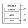
- FIG. 1 is a block diagram showing an example of a configuration of an information processing device.
- FIG. 1 is a block diagram showing an example of a configuration of an airport system.
- FIG. 1 is a plan view showing an example of a floor where boarding gates of an airport are provided.
- FIG. 11 is a plan view showing an example of a virtual authentication area.
- FIG. 13 is a block diagram showing another example of the configuration of the information processing device.
- FIG. 2 is a diagram illustrating an example of a face database included in the information processing device.
- FIG. 13 is a diagram for explaining passenger tracking processing.
- FIG. 13 is a diagram illustrating an example of an ID correspondence table.
- FIG. 2 illustrates an example of a terminal device. 10 is a flowchart showing a determination operation according to the second embodiment.
- FIG. 2 is a block diagram showing an example of a configuration of an authentication device.
- FIG. 11 is a plan view showing another example of the virtual authentication area.
- This section describes embodiments of an information processing device, an information processing method, and a recording medium.
- the information processing device 1 includes an image acquisition unit 11, a setting unit 12, and a determination unit 13.
- the setting unit 12 sets a first area including at least a part of a route along which people flow toward the facial recognition gate device based on gate information of multiple gate devices including the facial recognition gate device.
- the multiple gate devices may be installed in one location (e.g., one entrance/exit) or multiple locations (e.g., multiple entrance/exit).
- the gate information may include at least one of the operating status of each of the multiple gate devices, identification information of each of the multiple gate devices (i.e., information for identifying each gate device), location, and device type.
- the gate information may include at least one of the number of operating facial recognition gate devices, the location of the operating facial recognition gate, and identification information set for the facial recognition gate device.
- the operating state of the gate device may include an operating state (e.g., a state in which processing related to determining whether or not to allow a person to pass can be executed) and a dormant state (e.g., a state in which processing related to determining whether or not to allow a person to pass cannot be executed).
- the dormant state may include a state in which power is not supplied to the gate device (e.g., a power-off state) and a state in which power is supplied to a part of the gate device but the gate device cannot perform its function (so-called a standby state).
- the facial recognition gate device is not limited to a gate device that has only the function of determining whether or not to allow a person to pass by facial recognition processing, but may also include a gate device in which the function of determining whether or not to allow a person to pass by facial recognition processing is active (i.e., a gate device functioning as a facial recognition gate device) among gate devices that can switch between the function of determining whether or not to allow a person to pass by facial recognition processing and the function of determining whether or not to allow a person to pass by processing other than facial recognition processing (e.g., reading a two-dimensional barcode).
- the setting unit 12 may set the first area based on a map (e.g., a floor map) of a location where multiple gate devices are installed.
- the first area is an area that includes at least a part of a route along which people flow toward the facial recognition gate device.
- the setting unit 12 may estimate a route along which people flow toward the facial recognition gate device, for example, based on the position of the facial recognition gate device on the map and the shape of the passage leading to the facial recognition gate device.
- the setting unit 12 may set the first area based on the estimated route.
- the map e.g., a floor map
- the facility information may include store information and equipment information (e.g., at least one of toilets, stairs, escalators, and elevator halls).
- the setting unit 12 may set the first area based on the facility information included in the map. In this case, the setting unit 12 may estimate a route along which people flow toward the facial recognition gate device, based on the facility information.
- the first area may be a virtually set area. If the gate information indicates that the facial recognition gate device is not operating (i.e., if the facial recognition gate device is in a dormant state), the setting unit 12 does not need to set the first area. In other words, the setting unit 12 may set the first area only if the gate information indicates that the facial recognition gate device is operating.
- the facial recognition gate device allows people whose facial recognition has been successful to pass through, but does not allow people whose facial recognition has been unsuccessful to pass through (for example, if the facial recognition gate device is a flap-type gate device, the flap is closed).
- the facial recognition gate device may determine that facial recognition has been successful when the face of the person attempting to pass through the facial recognition gate device corresponds to a face shown in a pre-registered facial image. In other words, the facial recognition gate device may determine that facial recognition has been successful when there is a person whose facial image is registered in advance that corresponds to the person attempting to pass through the facial recognition gate device.
- the facial recognition gate device will not allow that person to pass through. For this reason, when a person whose facial image is not registered enters a facial recognition gate device, the flow of people passing through the facial recognition gate device is impeded because that person is not allowed to pass through. In other words, the throughput of the facial recognition gate device decreases.
- the image acquisition unit 11 acquires a first image, which is an image including the first area.
- the first image may be an image captured by a camera capable of capturing an image of the first area.
- the first image is an image including the first area. Therefore, the first image may include a person heading toward the facial recognition gate device.
- a person included in the first image and present in the first area is referred to as a first person to be authenticated.
- the determination unit 13 determines whether or not the first person to be authenticated can pass through the facial recognition gate device based on the result of facial recognition performed using the first image for the first person to be authenticated.
- the determination result by the determination unit 13 may be output to a display device (not shown).
- the display device may be provided in the information processing device 1 or may be a device different from the information processing device 1.
- at least one of a guide and a security guard near the facial recognition gate device can refer to the determination result by the determination unit 13 to determine who cannot pass through the facial recognition gate device.
- at least one of the guide and the security guard can guide people who cannot pass through the facial recognition gate device not to enter the facial recognition gate device. Therefore, according to the information processing device 1, it is possible to prevent people who cannot pass through the facial recognition gate device from entering the facial recognition gate device. Therefore, according to the information processing device 1, it is possible to prevent a decrease in the throughput of the facial recognition gate device.
- the setting unit 12 may set a first area including at least a part of a route along which people flow toward the facial recognition gate device based on gate information of multiple gate devices including the facial recognition gate device.
- the image acquisition unit 12 may acquire a first image that is an image including the first area.
- the determination unit 13 may determine whether or not a first authenticated person, who is included in the acquired first image and is a person present in the first area, can pass through the facial recognition gate device based on the result of facial recognition performed using the acquired first image.
- Such an information processing device 1 may be realized, for example, by a computer reading a computer program recorded on a recording medium.
- the recording medium can be said to have recorded thereon a computer program for causing a computer to execute an information processing method that sets a first area including at least a part of a route along which a flow of people heads toward the facial recognition gate device based on gate information of a plurality of gate devices including the facial recognition gate device, acquires a first image including the first area, and, for a first authenticated person who is included in the acquired first image and is present in the first area, determines whether or not the first authenticated person can pass through the facial recognition gate device based on the result of facial authentication performed using the acquired first image.
- Second Embodiment A second embodiment of the display control device, the display control method, and the recording medium will be described with reference to Fig. 2 to Fig. 12. In the following, the second embodiment of the display control device, the display control method, and the recording medium will be described using an information processing device 3 used in an airport.
- the airport system 2 of the airport will be described with reference to FIG. 2.
- the airport system 2 comprises a management server 21, a check-in terminal 22, and a plurality of gate devices installed at the boarding gates.
- the management server 21, the check-in terminal 22, and the plurality of gate devices are connected to each other via a network NW.
- the airport system 2 may include other check-in terminals in addition to the check-in terminal 22.
- the airport system 2 may include multiple check-in terminals.
- the network NW may be a wide area network (WAN) such as the Internet, or a local area network (LAN).
- WAN wide area network
- LAN local area network
- the multiple gate devices have a facial recognition function that performs facial recognition processing, and include a facial recognition gate device 23 that determines whether or not a passenger can pass based on the results of the facial recognition processing, and a gate device 24 that determines whether or not a passenger can pass based on the airline ticket held by the passenger.
- Gate device 24 will hereinafter be referred to as "normal gate device 24" as appropriate.
- the airport is provided with boarding gates G1, G2, and G3.
- the facial recognition gate device 23 and normal gate device 24 are provided at boarding gate G1.
- air ticket may mean at least one of a paper airline ticket and an electronic airline ticket.
- air ticket may also be a concept that includes something that indicates personal information associated with an electronic airline ticket (e.g., a passport, a credit card used to purchase the airline ticket, etc.).
- the management server 21 has a face database 211 (hereinafter referred to as “face DB 211”), an operation database 212 (hereinafter referred to as “operation DB 212”), and a gate database 213 (hereinafter referred to as “gate DB 213").
- Facial images used in facial recognition processing are registered in face DB211.
- features related to facial images may be registered in face DB211.
- Flight information (so-called flight information) of aircraft is registered in operation DB212. Flight information may include the flight name of the aircraft, gate identification information for identifying the boarding gate (e.g., boarding gate number), and boarding start time. Note that the flight name, identification information, and boarding start time of the aircraft may be associated with each other.
- Gate DB213 has registered therein a plurality of pieces of boarding gate information corresponding to a plurality of boarding gates.
- the person who manages and/or operates airport system 2 may be different from the airport company that manages and operates the airport and the airline that operates the aircraft.
- the plurality of pieces of boarding gate information registered in gate DB213 may be obtained from a system related to at least one of the airport company and the airline.
- Gate DB213 may be shared between airport system 2 and a system related to at least one of the airport company and the airline.
- the boarding gate information may include gate identification information (e.g., boarding gate number) for identifying the boarding gate, and device information related to the installed gate device.
- the device information may be information indicating the number of gate devices, and at least one of the type, operating status, and installation location of each gate device.
- the types of gate devices may include a first type capable of facial recognition, and a second type not capable of facial recognition.
- the second type of gate device may include a gate device capable of reading something (e.g., a two-dimensional barcode) that indicates information for identifying a passenger (e.g., an ID).
- the operating state of the gate device may include an operating state in which the gate device is operating and an inactive state in which the gate device is inactive (i.e., not operating).
- the installation position of the gate device may be expressed as the relative positional relationship of the two or more gate devices when, for example, two or more gate devices are installed at one boarding gate.
- the installation position of the gate device may be expressed as the coordinates of each gate device in a coordinate system related to the floor (so-called departure floor) on which the boarding gates of the airport are installed. Note that, when only one gate device is installed at one boarding gate, the device information does not need to include the installation position of the gate device.
- the multiple boarding gate information registered in the gate DB 213 may be determined in advance according to at least one of the airline and the flight of the aircraft.
- the multiple boarding gate information registered in the gate DB 213 may be automatically updated according to the departure time of the aircraft, etc.
- the boarding gate information corresponds to an example of "gate information" in the first embodiment.
- the check-in terminal 22 is a terminal used for boarding procedures (i.e., check-in).
- the check-in terminal 22 may be operated by airport staff or by passengers (i.e., the check-in terminal 22 may be a so-called automatic check-in machine).
- "airport staff" is not limited to people who belong to the airport company that manages and operates the airport, but also includes people who work at the airport, such as people who belong to the airlines that operate aircraft.
- the check-in terminal 22 performs check-in procedures for passengers based on the airline tickets held by the passengers.
- the check-in terminal 22 may acquire facial images of passengers during check-in procedures.
- the check-in terminal 22 may acquire facial images of passengers by capturing images of the passengers with a camera, or may acquire facial images of passengers by reading facial photographs printed on the passports held by the passengers. Note that the check-in terminal 22 does not have to acquire facial images of all passengers.
- the check-in terminal 22 transmits passenger information (e.g., name and flight number) of a passenger who has completed boarding procedures and a facial image of the passenger to the management server 21.
- the check-in terminal 22 may obtain the passenger information from information printed on the airline ticket (in other words, information associated with the airline ticket).
- the management server 21 registers the passenger information and facial image sent from the check-in terminal 22 in the face DB 211 in association with each other. At this time, the management server 21 may assign passenger identification information for identifying the passenger to the passenger information and facial image. As described below, the facial image is used in facial recognition processing. For this reason, the passenger identification information assigned to the passenger information and facial image will hereinafter be referred to as an "authentication ID" as appropriate.
- the passenger's facial image may be acquired by an application (e.g., an application provided by an airline) installed on a terminal device (e.g., a smartphone) carried by the passenger in addition to or instead of the check-in terminal 22, or may be acquired by a gate device installed in the immigration area of the airport.
- the management server 21 may identify, based on the current time, from the operation information registered in the operation DB 212, the flight name of an aircraft that is a first predetermined time (e.g., several minutes to several tens of minutes) before the boarding start time. Based on the gate identification information associated with the identified flight name, the management server 21 may extract boarding gate information corresponding to the above gate identification information from multiple boarding gate information registered in the gate DB 213. Based on the extracted boarding gate information, the management server 21 may determine whether or not a facial recognition gate device (e.g., facial recognition gate device 23) is installed at the boarding gate corresponding to the extracted boarding gate information.
- a facial recognition gate device e.g., facial recognition gate device 23
- the management server 21 may extract from the face DB 211 a facial image of a passenger associated with passenger information including the specified flight name (in other words, scheduled to board an aircraft with the specified flight name). The management server 21 may transmit the extracted facial image to a facial recognition gate device (e.g., facial recognition gate device 23) specified by the extracted boarding gate information. If it is determined that a facial recognition gate device is not installed, the management server 21 may not perform these processes. If it is determined that a facial recognition gate device is installed, the management server 21 may determine whether the installed facial recognition gate device is operating based on the extracted boarding gate information. If features related to a facial image are registered in the face DB 211, the management server 21 may transmit the features related to the facial image to the facial recognition gate device instead of or in addition to the facial image.
- a facial recognition gate device e.g., facial recognition gate device 23
- the facial recognition gate device 23 has a camera 231, a face database 232 (hereinafter referred to as "face DB 232"), and a facial recognition device 233. Face images transmitted from the management server 21 are registered in the face DB 232.
- the facial recognition gate device 23 may have a display device 234.
- the display device 234 may display at least one of an image captured by the camera 231 and information indicating the results of the facial recognition process.
- the facial recognition device 233 performs facial recognition processing using an image captured by the camera 231 (e.g., an image that includes the passenger's face) and a facial image registered in the face DB 232. If facial recognition is successful, the facial recognition gate device 23 allows the passenger to pass. On the other hand, if facial recognition is unsuccessful, the facial recognition gate device 23 does not allow the passenger to pass. Note that various existing methods (e.g., at least one of a two-dimensional (2D) authentication method and a three-dimensional (3D) authentication method) can be applied to the facial recognition processing.
- 2D two-dimensional
- 3D three-dimensional
- the face recognition gate device 23 may be a flap-type gate device.
- the face recognition device 233 may extract features of an image captured by the camera 231.
- the face recognition device 233 may compare the extracted features with features related to face images registered in the face DB 232. At this time, the face recognition device 233 may calculate a matching score (or a similarity score) based on the extracted features and features related to face images registered in the face DB 232. If the matching score is equal to or greater than a threshold (i.e., if face recognition is successful), the face recognition device 233 may allow the passenger to pass through. At this time, the face recognition device 233 may identify an authentication ID related to the passenger.
- the face recognition gate device 23 may open the flap. If the matching score is less than a threshold (i.e., if face recognition is unsuccessful), the face recognition device 233 may not allow the passenger to pass through. In this case, the facial recognition gate device 23 may close the flap.
- features related to the facial image may be registered in the face DB 232.
- a device e.g., the management server 21
- the facial recognition device 233 of the facial recognition gate device 23 may extract features of the image captured by the camera 231. The facial recognition device 233 may transmit the extracted features to the other device.
- the other device may compare the features transmitted from the facial recognition device 233 with features related to the facial image registered in a face database (e.g., the face DB 211).
- the other device may transmit information indicating the comparison result (e.g., information indicating whether the comparison score is equal to or greater than a threshold) to the facial recognition gate device 23.
- the comparison score is equal to or greater than a threshold
- the other device may include an authentication ID related to the passenger in the information indicating the comparison result. If the information indicating the matching result indicates that the matching score is equal to or greater than the threshold, the facial recognition device 233 may allow the passenger to pass. If the information indicating the matching result indicates that the matching score is less than the threshold, the facial recognition device 233 may not allow the passenger to pass.
- the facial recognition gate device 23 is expected to enable passengers to pass through at a faster rate than the normal gate device 24. In other words, the number of passengers passing through the facial recognition gate device 23 in a given period of time is expected to be greater than the number of passengers passing through the normal gate device 24. In other words, the facial recognition gate device 23 can improve throughput at the boarding gate.
- the facial recognition gate device 23 only passengers whose faces have been successfully authenticated can pass through the facial recognition gate device 23.
- the passenger's facial image must be registered in the face DB 232 of the facial recognition gate device 23. If a passenger whose facial image is not registered in the face DB 232 enters the facial recognition gate device 23, the throughput at the boarding gate will decrease because the passenger will not be allowed to pass through.
- the information processing device 3 determines whether or not a passenger can pass through the facial recognition gate device 23 before the passenger enters the facial recognition gate device 23. In other words, the information processing device 3 determines whether or not a passenger can pass through the facial recognition gate device 23 separately from the facial recognition gate device 23.
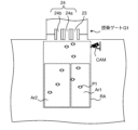
- a virtual authentication area RA is provided around boarding gate G1 where face recognition gate device 23 and normal gate device 24 are installed.
- the authentication area RA is an area through which multiple passengers heading to either face recognition gate device 23 or normal gate device 24 pass.
- the camera CAM is installed so that it can capture the authentication area RA.
- the camera CAM may be connected to the information processing device 3 via the network NW.
- the camera CAM does not have to be installed so that the entire authentication area RA is included within its viewing angle. In other words, the camera CAM may be installed so that it can capture at least a part of the authentication area RA.
- the camera CAM may be installed in a position that does not interfere with the passage of passengers (for example, a position higher than the passenger's head). As described later, the image captured by the camera CAM may be used for face recognition processing. For this reason, the camera CAM may be a high-resolution camera such as a 4K resolution camera.
- the camera CAM does not have to be connected to the information processing device 3 via the network NW. In this case, the camera CAM may be connected to the information processing device 3 via a cable (for example, a USB (Universal Serial Bus) cable).
- a cable for example, a USB (Universal Serial Bus) cable
- the camera CAM may capture an image of the authentication area RA to generate a first image that includes the authentication area RA.
- the first image may be an image that corresponds to one frame of a video.
- the information processing device 3 performs face recognition processing using a first image generated by the camera CAM capturing an image of the recognition area RA, and determines whether or not a passenger included in the first image is able to pass through the face recognition gate device 23 before the passenger enters the face recognition gate device 23.
- the information processing device 3 will be described in detail below.
- the information processing device 3 includes a calculation device 31, a storage device 32, and a communication device 33.
- the information processing device 3 may include an input device 34 and an output device 35.
- the information processing device 3 may include a face database 36 (hereinafter, referred to as "face DB 36").
- face DB 36 a face database 36
- the information processing device 3 may not include at least one of the input device 34 and the output device 35.
- the calculation device 31, the storage device 32, the communication device 33, the input device 34, the output device 35, and the face DB 36 may be connected via a data bus 37.
- the information processing device 3 is connected to the management server 21 via the communication device 33 and the network NW.
- the information processing device 3 may constitute a part of the airport system 2. In other words, the airport system 2 may include the information processing device 3.
- the computing device 31 may include, for example, at least one of a CPU (Central Processing Unit), a GPU (Graphics Processing Unit), an FPGA (Field Programmable Gate Array), a TPU (Tensor Processing Unit), and a quantum processor.
- a CPU Central Processing Unit
- GPU Graphics Processing Unit
- FPGA Field Programmable Gate Array
- TPU Torsor Processing Unit
- quantum processor a quantum processor
- the storage device 32 may include, for example, at least one of a RAM (Random Access Memory), a ROM (Read Only Memory), a hard disk device, a magneto-optical disk device, a Solid State Drive (SSD), and an optical disk array.
- the storage device 32 may include a non-transient recording medium.
- the storage device 32 is capable of storing desired data.
- the storage device 32 may temporarily store a computer program executed by the arithmetic device 31.
- the storage device 32 may temporarily store data that is temporarily used by the arithmetic device 31 when the arithmetic device 31 is executing a computer program.
- the communication device 33 is capable of communicating with the management server 21 via the network NW.
- the communication device 33 may also be capable of communicating with devices external to the information processing device 3 other than the management server 21 via the network NW.
- the communication device 33 may perform wired communication or wireless communication.
- the input device 34 is a device capable of accepting information input to the information processing device 3 from the outside. It may include an operating device (e.g., a keyboard, a mouse, a touch panel, etc.) that can be operated by an operator of the information processing device 3.
- the input device 34 may include a recording medium reading device that can read information recorded on a recording medium that is detachable from the information processing device 3, such as a USB memory. Note that when information is input to the information processing device 3 via the communication device 33 (in other words, when the display control device 2 obtains information via the communication device 33), the communication device 33 may function as an input device.
- the output device 35 is a device capable of outputting information to the outside of the information processing device 3.
- the output device 35 may output visual information such as characters and images, auditory information such as sound, or tactile information such as vibration, as the above information.
- the output device 35 may include at least one of a display, a speaker, a printer, and a vibration motor, for example.
- the output device 35 may be capable of outputting information to a recording medium that is detachable from the information processing device 3, such as a USB memory. Note that when the information processing device 3 outputs information via the communication device 33, the communication device 33 may function as an output device.
- the calculation device 31 may have, as logically realized functional blocks or as physically realized processing circuits, an image acquisition unit 311, an information acquisition unit 312, a setting unit 313, a tracking unit 314, a face authentication unit 315, a determination unit 316, and a guidance unit 317. At least one of the image acquisition unit 311, the information acquisition unit 312, the setting unit 313, the tracking unit 314, the face authentication unit 315, the determination unit 316, and the guidance unit 317 may be realized in a form that mixes logical functional blocks and physical processing circuits (i.e., hardware).
- the image acquisition unit 311, the information acquisition unit 312, the setting unit 313, the tracking unit 314, the face authentication unit 315, the determination unit 316, and the guidance unit 317 are functional blocks
- at least some of the image acquisition unit 311, the information acquisition unit 312, the setting unit 313, the tracking unit 314, the face authentication unit 315, the determination unit 316, and the guidance unit 317 may be realized by the calculation device 31 executing a predetermined computer program.
- the arithmetic device 31 may obtain (in other words, read) the above-mentioned specific computer program from the storage device 32.
- the arithmetic device 31 may read the above-mentioned specific computer program stored in a computer-readable and non-transient recording medium using a recording medium reading device (not shown) provided in the information processing device 3.
- the arithmetic device 31 may obtain (in other words, download or read) the above-mentioned specific computer program from a device (not shown) external to the information processing device 3 via the communication device 33.
- the recording medium for recording the above-mentioned specific computer program executed by the arithmetic device 31 may be at least one of an optical disk, a magnetic medium, a magneto-optical disk, a semiconductor memory, and any other medium capable of storing a program.
- the management server 21 transmits at least a part of the facial image registered in the face DB 211 together with the authentication ID (i.e., passenger identification information) assigned to the facial image to the information processing device 3.
- the management server 21 may transmit gate identification information and boarding start time in addition to the facial image to the information processing device 3.
- the management server 21 may identify the gate identification information and boarding start time based on the flight name of the aircraft included in the passenger information associated with the facial image registered in the face DB 211 and the operation information registered in the operation DB 212. In other words, the management server 21 may identify the gate identification information and boarding start time related to the aircraft on which the passenger indicated by the facial image is boarding. Note that, if feature amounts related to the facial image are registered in the face DB 211 instead of or in addition to the facial image, the management server 21 may transmit the feature amounts related to the facial image instead of or in addition to the facial image to the display control device 3.
- the information processing device 3 registers the facial image transmitted from the management server 21 in the face DB 36.
- the information processing device 3 may register gate identification information and boarding start time in the face DB 36 in addition to the facial image.
- the face DB 36 may include (i) a plurality of facial images and (ii) a table that associates an authentication ID, gate identification information (e.g., boarding gate number), boarding start time, and facial image with each other.
- the management server 21 may transmit at least a part of the facial images registered in the face DB 211 to the information processing device 3 at a predetermined cycle.
- the information processing device 3 may update the facial images registered in the face DB 36 every time a facial image is transmitted from the management server 21.
- the management server 21 transmits a feature amount related to the facial image to the display control device 3 instead of or in addition to the facial image
- the feature amount related to the facial image may be registered in the face DB 36 instead of or in addition to the facial image.
- the image acquisition unit 311 of the calculation device 31 may acquire one or more first images generated by the camera CAM via the communication device 33.
- the image acquisition unit 311 may store the acquired one or more first images in the storage device 32.
- the information acquisition unit 312 of the calculation device 31 acquires boarding gate information related to boarding gate G1 from the gate DB 213 of the management server 21 via the communication device 33.
- the information acquisition unit 312 may store the acquired boarding gate information in the storage device 32.
- the setting unit 313 of the calculation device 31 may identify the gate device installed at the boarding gate G1 based on the device information included in the boarding gate information related to the boarding gate G1.
- the face recognition gate device 23 and normal gate devices 24a and 24b as the normal gate device 24 are installed at the boarding gate G1 (see FIG. 4).
- the setting unit 313 may identify which of the identified gate devices is in operation based on the device information.
- the setting unit 313 may identify the location of the gate device in operation based on the device information. Here, it is assumed that the face recognition gate device 23 and the normal gate devices 24a and 24b are in operation.
- the setting unit 313 may set a virtual area Ar1 including at least a portion of the route along which people flow toward the facial recognition gate device 23 based on the position of the facial recognition gate device 23 (see FIG. 4).
- the setting unit 313 may set a virtual area Ar2 including at least a portion of the route along which people flow toward the normal gate devices 24a and 24b based on the positions of the normal gate devices 24a and 24b (see FIG. 4).
- areas Ar1 and Ar2 are set as areas within the authentication area RA. However, at least a portion of area Ar1 may be outside the authentication area RA. Similarly, at least a portion of area Ar2 may be outside the authentication area RA.
- the setting unit 313 does not need to set the area Ar1.
- the setting unit 313 does not need to set the area Ar2.
- the setting unit 313 may change at least one of the position and size of the area Ar2 based on the position of one of the normal gate devices 24a and 24b.
- the setting unit 313 may determine whether to set an area (e.g., at least one of areas Ar1 and Ar2) based on the operating state of each of a plurality of gate devices including the facial recognition gate device 23 and the normal gate devices 24a and 24b, and may determine at least one of the position and size of the area to be set.
- the setting unit 313 may associate the set area with device identification information for identifying the gate device.
- the setting unit 313 may associate the area Ar1 with device identification information related to the facial recognition gate device 23.
- the setting unit 313 may associate the area Ar2 with device identification information related to each of the normal gate devices 24a and 24b.
- the operation state of each of the multiple gate devices may be changed according to the flight information of the aircraft.
- the operation state of the gate device may be changed from an active state to an inactive state when the current time passes the departure time of an aircraft.
- the operation state of the gate device may be changed from an inactive state to an active state when the current time is a second predetermined time (e.g., 30 minutes) before the boarding start time of an aircraft.
- the setting unit 313 may acquire boarding gate information from the gate DB 213 of the management server 21 based on the flight information of the aircraft. For example, when the current time passes the departure time of an aircraft, the setting unit 313 may acquire boarding gate information from the gate DB 213.
- the setting unit 313 may cancel the setting of the area (e.g., at least one of the areas Ar1 and Ar2) that was set when the gate device was in an active state. For example, when the current time is a second predetermined time before the boarding start time of an aircraft, the setting unit 313 may acquire boarding gate information from the gate DB 213. Then, for a gate device whose operating state has been changed from a dormant state to an active state, the setting unit 313 may set a new area (for example, at least one of areas Ar1 and Ar2) according to the position of the gate device.
- a new area for example, at least one of areas Ar1 and Ar2
- the operational state of the gate device may be determined in advance for each flight of an aircraft. That is, the operational state of each of the multiple gate devices when boarding one aircraft and the operational state of each of the multiple gate devices when boarding another aircraft may be determined in advance. For example, when the current time has passed the departure time of the one aircraft, or when the current time is a second predetermined time before the boarding start time of the other aircraft, the setting unit 313 may acquire boarding gate information when boarding the other aircraft from the gate DB 213. In this case, the setting unit 313 may change the area (e.g., at least one of areas Ar1 and Ar2) that was set when boarding the one aircraft based on the acquired boarding gate information (specifically, the operational state of the gate device).
- the area e.g., at least one of areas Ar1 and Ar2
- the setting unit 313 may change the size of the area Ar1 according to the number of facial recognition gate devices 23 installed at the boarding gate G1.
- the setting unit 313 may change the position of the area Ar1 according to the position of the facial recognition gate device 23 at the boarding gate G1.
- the setting unit 313 may determine the vertical width of the area Ar1 (e.g., the width in the direction along the travel direction when the passenger passes through the facial recognition gate device 23) according to the number of facial recognition gate devices 23 installed at the boarding gate G1, and may determine the horizontal width of the area Ar1 (e.g., the width in the direction intersecting the travel direction when the passenger passes through the facial recognition gate device 23) according to the position of the facial recognition gate device 23.
- the setting unit 313 may determine at least one of the maximum value and the minimum value of each of the vertical width and the horizontal width of the area Ar1 based on the floor map of the airport.
- the setting unit 313 may determine the shape of the area Ar1 (e.g., square, rectangular, L-shaped, etc.) based on the floor map of the airport.
- the setting unit 313 may change the size of the area Ar2 according to the number of normal gate devices 24 installed at the boarding gate G1.
- the setting unit 313 may change the position of the area Ar2 according to the position of the normal gate device 24 at the boarding gate G1.
- the setting unit 313 may determine the vertical width of the area Ar2 (e.g., the width in the direction along the travel direction when the passenger passes through the normal gate device 24) according to the number of normal gate devices 24 installed at the boarding gate G1, and may determine the horizontal width of the area Ar2 (e.g., the width in the direction intersecting the travel direction when the passenger passes through the normal gate device 24) according to the position of the normal gate device 24.
- the setting unit 313 may determine at least one of the maximum value and minimum value of each of the vertical width and horizontal width of the area Ar2 based on the floor map of the airport.
- the setting unit 313 may determine the shape of the area Ar2 (e.g., square, rectangular, L-shaped, etc.) based on the floor map of the airport.
- Facility information may also be included in the airport floor map.
- the facility information may include store information and equipment information (e.g., at least one of toilets, stairs, escalators, and elevator halls).
- the operation patterns of multiple gate devices at a certain boarding gate may be associated in advance with the position and size of an area (e.g., at least one of areas Ar1 and Ar2).
- the setting unit 313 may identify the above-mentioned operation pattern based on the boarding gate information acquired from the gate DB 213. Then, the setting unit 313 may set the area based on the position and size of the area associated with the identified operation pattern.
- the tracking unit 314 of the calculation device 31 uses the multiple first images acquired by the image acquisition unit 311 (i.e., the multiple first images generated by the camera CAM) to track one or more passengers passing through the authentication area RA.
- the face recognition unit 315 of the calculation device 31 uses the multiple first images acquired by the image acquisition unit 311 to perform face recognition processing of one or more passengers passing through the authentication area RA.
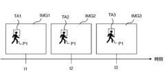
- Images IMG1, IMG2, and IMG3 shown in FIG. 7 are images that include passenger P1 (in other words, images in which passenger P1 is captured).
- Image IMG1 is an image generated by camera CAM capturing an image of authentication area RA at time t1.
- Image IMG2 is an image generated by camera CAM capturing an image of authentication area RA at time t2, which is later than time t1.
- Image IMG3 is an image generated by camera CAM capturing an image of authentication area RA at time t3, which is later than time t2.
- Each of images IMG1, IMG2, and IMG3 may be an image corresponding to one frame of a video.
- image IMG2 does not have to be an image corresponding to the frame immediately following the frame corresponding to image IMG1.
- image IMG2 may be an image corresponding to a frame that is two or more frames later than the frame corresponding to image IMG1.
- image IMG3 does not have to be an image corresponding to the frame immediately following the frame corresponding to image IMG2.
- image IMG3 may be an image corresponding to a frame that is two or more frames later than the frame corresponding to image IMG2.
- the tracking unit 314 detects the head of passenger P1 contained in image IMG1 from image IMG1. Note that existing technology is applied to the method of detecting a person's head from an image, so a detailed explanation is omitted. Based on the detected head of passenger P1, the tracking unit 314 sets the area including the head of passenger P1 as a tracking area TA1.
- the tracking unit 314 sets the tracking area TA1, it sets a tracking ID, which is identification information for identifying the passenger P1 related to the tracking area TA1, to the passenger P1.
- the tracking unit 314 calculates the position of the passenger P1 based on the tracking area TA1. Note that since existing technology can be applied to a method for calculating the position of a subject contained in an image from the image, a detailed explanation is omitted.
- the tracking unit 314 may register the tracking ID and the position of the passenger P1 in an ID correspondence table 321 stored in the storage device 32 in correspondence with each other.
- the tracking unit 314 may determine whether or not the face of passenger P1 is reflected in the tracking area TA1. In other words, the tracking unit 314 may perform face detection on the tracking area TA1. When it is determined that the face of passenger P1 is reflected in the tracking area TA1, the tracking unit 314 generates a face image including the face area of passenger P1. The tracking unit 314 associates the generated face image with the tracking ID related to passenger P1 and transmits it to the face authentication unit 315. Note that when it is determined that the face of passenger P1 is not reflected in the tracking area TA1, the tracking unit 314 does not need to generate a face image.
- the face authentication unit 315 performs face authentication processing using the face image sent from the tracking unit 314 and the face images registered in the face DB 36 .
- the face authentication unit 315 may extract features of the face image transmitted from the tracking unit 314.
- the face authentication unit 315 may compare the features of the face image transmitted from the tracking unit 314 with features related to the face image registered in the face DB 36.
- the face authentication unit 315 may calculate a matching score (or a similarity score) based on the extracted features and the features related to the face image registered in the face DB 36.
- the face authentication unit 315 may compare the matching score with a threshold.
- the face authentication unit 315 may determine that the face indicated by the face image transmitted from the tracking unit 314 corresponds to a face indicated by one of the face images registered in the face DB 36. If the matching score is less than the threshold, the face authentication unit 315 may determine that a face image indicating a face corresponding to the face indicated by the face image transmitted from the tracking unit 314 is not registered in the face DB 36.
- the facial authentication unit 315 registers the authentication ID associated with the one facial image in the ID correspondence table 321 in association with the tracking ID associated with the facial image transmitted from the tracking unit 314. In addition to the authentication ID, the facial authentication unit 315 may register the authentication time, which is the time when the facial authentication process was performed, in the ID correspondence table 321.
- the facial authentication unit 315 may register information indicating that there is no corresponding person (e.g., "N/A (Not Applicable)" in the ID correspondence table 321 by associating it with the tracking ID associated with the facial image transmitted from the tracking unit 314.
- the tracking unit 314 may use images IMG2 and IMG1 to identify passenger P1 included in image IMG2. Identifying passenger P1 included in image IMG2 is synonymous with associating passenger P1 included in image IMG1 with passenger P1 included in image IMG2. Therefore, at least one of a matching method and an optical flow method for associating images can be applied to identify passenger P1 included in image IMG2. Note that since various existing aspects can be applied to each of the matching method and optical flow method, detailed explanations thereof will be omitted.
- the tracking unit 314 detects the head of passenger P1. Based on the detected head of passenger P1, the tracking unit 314 sets the area including the head of passenger P1 as tracking area TA2. Since passenger P1 included in image IMG1 and passenger P1 included in image IMG2 are the same passenger, the tracking ID of passenger P1 related to tracking area TA2 is the same as the tracking ID of passenger P1 related to tracking area TA1. The tracking unit 314 calculates the position of passenger P1 based on tracking area TA2.
- the tracking unit 314 registers the position of passenger P1 in the ID correspondence table 321 in association with the tracking ID related to passenger P1. In this case, since the position of passenger P1 calculated based on tracking area TA1 is registered in the ID correspondence table 321, the tracking unit 314 registers the position of passenger P1 calculated based on tracking area TA2 in the ID correspondence table 321, thereby updating the position of passenger P1.
- the tracking unit 314 may determine whether or not the face of the passenger P1 is reflected in the tracking area TA2. In other words, the tracking unit 314 may perform face detection on the tracking area TA2. When it is determined that the face of the passenger P1 is reflected in the tracking area TA2, the tracking unit 314 generates a face image including the face area of the passenger P1. The tracking unit 314 transmits the generated face image to the face authentication unit 315 in association with the tracking ID related to the passenger P1. Note that, when it is determined that the face of the passenger P1 is not reflected in the tracking area TA2, the tracking unit 314 does not need to generate a face image.
- the tracking unit 314 does not need to generate a face image.
- the face authentication unit 315 performs face authentication processing using the face image sent from the tracking unit 314 and the face image registered in the face DB 36. If the face shown by the face image sent from the tracking unit 314 corresponds to the face shown by one of the face images registered in the face DB 36 (in other words, if face authentication is successful), the face authentication unit 315 registers the authentication ID associated with the one face image in the ID correspondence table 321 in association with the tracking ID associated with the face image sent from the tracking unit 314. In addition to the authentication ID, the face authentication unit 315 may register the authentication time, which is the time when the face authentication processing was performed, in the ID correspondence table 321. Note that if the authentication time has already been registered in the ID correspondence table 321 (i.e., if face authentication was successful in the past), the face authentication unit 315 may update the authentication time registered in the ID correspondence table 321.
- the facial recognition unit 315 may register information indicating that there is no corresponding person in the ID correspondence table 321 by associating it with the tracking ID associated with the facial image sent from the tracking unit 314.
- the tracking unit 314 may use the images IMG3 and IMG2 to identify passenger P1 included in image IMG3.
- the tracking unit 314 detects the head of passenger P1.
- the tracking unit 314 sets an area including the head of passenger P1 as tracking area TA3. Since passenger P1 included in image IMG2 and passenger P1 included in image IMG3 are the same passenger, the tracking ID of passenger P1 related to tracking area TA3 is the same as the tracking ID of passenger P1 related to tracking area TA2.
- the tracking unit 314 calculates the position of passenger P1 based on tracking area TA3.
- the tracking unit 314 registers the position of passenger P1 in the ID correspondence table 321 in association with the tracking ID related to passenger P1. In this case, since the position of passenger P1 calculated based on tracking area TA2 is registered in the ID correspondence table 321, the tracking unit 314 registers the position of passenger P1 calculated based on tracking area TA3 in the ID correspondence table 321, thereby updating the position of passenger P1.
- the tracking unit 314 may determine whether or not the face of the passenger P1 is reflected in the tracking area TA3. In other words, the tracking unit 314 may perform face detection on the tracking area TA3. When it is determined that the face of the passenger P1 is reflected in the tracking area TA3, the tracking unit 314 generates a face image including the face area of the passenger P1. The tracking unit 314 transmits the generated face image to the face authentication unit 315 in association with the tracking ID related to the passenger P1. Note that, when it is determined that the face of the passenger P1 is not reflected in the tracking area TA3, the tracking unit 314 does not need to generate a face image.
- the tracking unit 314 does not need to generate a face image.
- the face authentication unit 315 performs face authentication processing using the face image sent from the tracking unit 314 and the face image registered in the face DB 36. If the face shown by the face image sent from the tracking unit 314 corresponds to the face shown by one of the face images registered in the face DB 36 (in other words, if face authentication is successful), the face authentication unit 315 registers the authentication ID associated with the one face image in the ID correspondence table 321 in association with the tracking ID associated with the face image sent from the tracking unit 314. In addition to the authentication ID, the face authentication unit 315 may register the authentication time, which is the time when the face authentication processing was performed, in the ID correspondence table 321. Note that if the authentication time has already been registered in the ID correspondence table 321 (i.e., if face authentication has been successful in the past), the face authentication unit 315 may update the authentication time registered in the ID correspondence table 321.
- the facial recognition unit 315 may register information indicating that there is no corresponding person in the ID correspondence table 321, in association with the tracking ID associated with the facial image sent from the tracking unit 314.
- the tracking unit 314 and the face authentication unit 315 may repeat the above-mentioned process until passenger P1 passes through the authentication area RA. As described above, the tracking unit 314 calculates the position of passenger P1. In other words, it can be said that the tracking unit 314 detects the position of passenger P1. For this reason, the tracking unit 314 may be referred to as a position detection means.
- a tracking ID, a tracking position (e.g., the position of passenger P1), an authentication ID, and an authentication time may be associated with each other.
- a tracking ID is associated with a specific authentication ID in the ID correspondence table 321 this indicates that a facial image of a person corresponding to the passenger to whom the tracking ID is set is registered in the face DB 36.
- a tracking ID is associated with the character string "N/A"
- this indicates that a facial image of a person corresponding to the passenger to whom the tracking ID is set is not registered in the face DB 36.
- a tracking ID is not associated with an authentication ID (i.e., when the authentication ID field is blank), this indicates that facial recognition processing has never been performed.
- the tracking unit 314 may perform the following process. After tracking of passenger P1 is interrupted, the tracking unit 314 may determine whether a new passenger has been detected from the first image acquired by the image acquisition unit 311 (i.e., the first image generated by the camera CAM). A "new passenger" refers to a passenger for whom a tracking ID has not been set.
- the tracking unit 314 may compare the feature amount of the tracking area (e.g., at least one of the tracking areas TA1, TA2, and TA3) related to passenger P1 with the feature amount of the tracking area related to the new passenger to determine whether passenger P1 and the new passenger are the same person. If it is determined that passenger P1 and the new passenger are the same person, the tracking unit 314 may set the tracking ID related to passenger P1 to the new passenger. As a result, the tracking unit 314 can track passenger P1 again.
- the feature amount may be a feature amount related to the passenger's head, a feature amount related to the passenger's upper body, or a feature amount related to the passenger's entire body. Therefore, the tracking area may include the passenger's head, the passenger's upper body, or the passenger's entire body.
- the feature amount may be obtained, for example, by Person Re-Identification technology.
- the tracking unit 314 and the face authentication unit 315 may perform the above-mentioned tracking process and face authentication process for each of the multiple passengers included in one first image generated by the camera CAM.
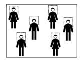
- the authentication area RA may be, for example, an area of 5 meters by 5 meters. A distance of 5 meters is a distance that allows 5 to 6 passengers to pass in a horizontal line. If the authentication area RA is an area of 5 meters by 5 meters, 20 to 30 passengers may be present within the authentication area RA. Therefore, as shown in FIG. 9, the information processing device 3 can perform tracking process and face authentication process for multiple passengers based on one first image generated by the camera CAM. Note that the multiple dotted rectangles in FIG. 9 represent the tracking area.
- the tracking area (e.g., at least one of tracking areas TA1, TA2, and TA3) may include not only the head of the passenger (e.g., passenger P1) for which the tracking unit 314 performs tracking processing, but also parts of the passenger other than the head (e.g., shoulders).
- the tracking area may be set to include the upper body of the passenger, or may be set to include the entire body of the passenger.
- the tracking unit 314 detects one or more passengers (i.e., people) from the first image acquired by the image acquisition unit 311 (i.e., the first image generated by the camera CAM) (step S101).
- the tracking unit 314 may detect the head of the passenger.
- the tracking unit 314 may set a tracking area including the detected head of the passenger based on the detected head of the passenger.
- the tracking unit 314 may perform face detection of the detected one or more passengers.
- the tracking unit 314 uses another first image acquired by the image acquisition unit 311 to perform a tracking process of at least one of the one or more passengers detected in the process of step S101 (step S102).
- the tracking unit 314 may perform face detection of the detected one or more passengers. If the face of at least one of the one or more passengers is detected in the process of at least one of steps S101 and S102, the tracking unit 314 transmits a face image including the facial area of at least one person to the face authentication unit 315.
- the face authentication unit 315 performs face authentication processing using the face image sent from the tracking unit 314 (step S103).
- the face authentication unit 315 registers the result of the face authentication processing in the ID correspondence table 321, or updates the ID correspondence table 321 based on the result of the face authentication processing (step S104).
- the determination unit 316 obtains the position of passenger P2 from the ID correspondence table 321 based on the tracking ID related to passenger P2.
- the position of passenger P2 may be represented by the value of the tracking position associated with the tracking ID related to passenger P2 in the ID correspondence table 321.
- the determination unit 316 may determine whether or not passenger P2 can pass through the facial recognition gate device 23 based on the ID correspondence table 321. If the tracking ID for passenger P2 is associated with a specific authentication ID in the ID correspondence table 321, the determination unit 316 may determine that passenger P2 can pass through the facial recognition gate device 23. If the tracking ID for passenger P2 is associated with the character string "N/A" in the ID correspondence table 321, or if the tracking ID for passenger P2 is not associated with an authentication ID (i.e., if the authentication ID field is blank), the determination unit 316 may determine that passenger P2 cannot pass through the facial recognition gate device 23.
- the determination unit 316 may determine that passenger P2 will use the facial recognition gate device 23.
- the determination unit 316 acquires information related to area Ar1 (e.g., information indicating at least one of the position and size of area Ar1) associated with the device identification information related to the facial recognition gate device 23.
- the determination unit 316 may acquire information related to area Ar1 from the setting unit 313.
- the determination unit 316 determines whether or not passenger P2 is in area Ar1 based on the position of passenger P2 and information related to area Ar1.
- area Ar1 is an area that includes at least a portion of a route along which people flow toward the facial recognition gate device 23. If it is determined that passenger P2 is in area Ar1, the determination unit 316 determines that passenger P2 is heading toward the facial recognition gate device 23. If it is determined that passenger P2 is not in area Ar1, the determination unit 316 determines that passenger P2 is not heading toward the facial recognition gate device 23. In this case, the determination unit 316 transmits information indicating passenger P2 and information indicating the gate device that passenger P2 should use to the guidance unit 317.
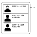
- the guidance unit 317 may transmit information indicating passenger P2 and information indicating the gate device that passenger P2 should use to a terminal device 4 (see FIG. 11) used by airport staff (e.g., at least one of a guidance staff member and a security guard) near boarding gate G1. As a result, a screen such as that shown in FIG. 11 may be displayed on the terminal device 4.
- the airport staff may guide passenger P2 to the facial recognition gate device 23 based on the information displayed on the terminal device 4.
- the information processing device 3 may be connected to a terminal device 4 via a network NW.
- the terminal device 4 may be configured as any one of a tablet terminal, a smartphone, and a notebook PC (Personal Computer).
- the determination unit 316 may determine that passenger P2 will use the normal gate device 24a or 24b.
- the determination unit 316 acquires information related to the area Ar2 (e.g., information indicating at least one of the position and size of the area Ar2) associated with the device identification information related to the normal gate device 24a or 24b.
- the determination unit 316 may acquire the information related to the area Ar2 from the setting unit 313.
- the determination unit 316 determines whether or not passenger P2 is in area Ar2 based on the position of passenger P2 and information related to area Ar2.
- area Ar2 is an area that includes at least a portion of a route along which there is a flow of people heading toward the normal gate devices 24a and 24b. If it is determined that passenger P2 is in area Ar2, the determination unit 316 determines that passenger P2 is heading toward one of the normal gate devices 24a and 24b. If it is determined that passenger P2 is not in area Ar2, the determination unit 316 determines that passenger P2 is not heading toward one of the normal gate devices 24a and 24b. In this case, the determination unit 316 transmits information indicating passenger P2 and information indicating the gate device that passenger P2 should use to the guidance unit 317.
- the guidance unit 317 may transmit information indicating passenger P2 and information indicating the gate device that passenger P2 should use to the terminal device 4. Based on the information displayed on the terminal device 4, airport staff may guide passenger P2 to one of the normal gate devices 24a and 24b.
- the guidance unit 317 may, for example, emit a voice via a speaker (not shown) to guide passenger P2 to the facial recognition gate device 23, or may project an image via a projection device (not shown) to guide passenger P2 to the facial recognition gate device 23.
- the guidance unit 317 may, for example, transmit information indicating the gate device that passenger P2 should use to a mobile device (e.g., at least one of a smartphone and a tablet device) carried by passenger P2.
- the determination unit 316 acquires the position of a passenger as a target person (e.g., passenger P2) from the ID correspondence table 321 based on the tracking ID related to the passenger (step S201).
- the determination unit 316 may determine the gate device used by the passenger based on the tracking ID related to the passenger and the ID correspondence table 321.
- the determination unit 316 acquires device identification information related to the gate device used by the passenger (step S202).
- the determination unit 316 obtains information related to the area (e.g., one of areas Ar1 and Ar2) associated with the gate device used by the passenger based on the device identification information obtained in the processing of step S202 (step S203). The determination unit 316 determines whether the passenger is in a specified area based on the passenger's position obtained in the processing of step S201 and the area-related information obtained in the processing of step S203 (step S204).
- the "specified area” means the area associated with the gate device used by the passenger.
- step S204: Yes the determination unit 316 may change the target person (e.g., from one passenger to another passenger) and perform the processing of step S201. If it is determined in the processing of step S204 that the passenger is not within the specified area (step S204: No), the determination unit 316 may transmit information indicating the passenger and information indicating the gate device that the passenger should use to the guidance unit 317 (step S205). Thereafter, the determination unit 316 may change the target person and perform the processing of step S201.
- the target person e.g., from one passenger to another passenger
- step S205 the determination unit 316 may change the target person and perform the processing of step S201.
- the determination unit 316 may determine whether the gate device is operating based on the boarding gate information.
- the operations of the information processing device 3 described above may be realized by the information processing device 3 reading a computer program recorded on a recording medium. In this case, it can be said that the recording medium has recorded thereon a computer program for causing the information processing device 3 to execute the operations described above.
- the information processing device 3 determines whether each of the passengers is heading toward the gate device to be used based on the position of each of the passengers and information related to the area (e.g., one of the areas Ar1 and Ar2) associated with the gate device to be used by each of the passengers.
- the information processing device 3 may transmit, for example, to the terminal device 4, information indicating a passenger among the passengers who is not heading toward the gate device to be used and information indicating the gate device to be used by that passenger.
- airport staff e.g., at least one of a guide and a security guard
- the information processing device 3 can prevent those who cannot pass through the facial recognition gate device 23 from entering the facial recognition gate device 23. Therefore, the information processing device 3 can prevent a decrease in the throughput of the facial recognition gate device 23.
- the information processing device 3 may be applied to, for example, at least one of the security gates at airports (i.e., gates installed at security checkpoints at airports) and immigration gates.
- the display control device 3 may be applied to, for example, at least one of offices, train stations, theme parks, and event venues that use face recognition gate devices for at least one of entry and exit.
- the information processing device 3 (specifically, the face authentication unit 315) performs face authentication processing.
- the information processing device 3 does not have to perform face authentication processing.
- the information processing device 3 does not have to include the face authentication unit 315 and the face DB 36.
- the face authentication processing may be performed by an authentication device 5 different from the information processing device 3.
- the information processing device 3 and the authentication device 5 may be connected via a network NW.
- the information processing device 3 and the authentication device 5 may constitute one system.
- the one system may be referred to as an information processing system or an authentication system.
- the authentication device 5 includes a face authentication unit 51 and a face database 52 (hereinafter referred to as "face DB 52").
- the face authentication unit 51 is configured to be able to execute face authentication processing.
- the authentication device 5 is an authentication device having a face authentication function.
- the management server 21 of the airport system 2 may transmit at least a part of the face image registered in the face DB 211 to the authentication device 5 together with an authentication ID (i.e., passenger identification information) assigned to the face image.
- the management server 21 may transmit gate identification information and boarding start time in addition to the face image to the authentication device 5.
- the authentication device 5 may register the face image transmitted from the management server 21 in the face DB 52.
- the authentication device 5 may register gate identification information and boarding start time in addition to the face image in the face DB 52.
- the tracking unit 312 of the information processing device 3 may detect a passenger (e.g., passenger P1) included in the image acquired by the image acquisition unit 311.
- the tracking unit 312 may set a tracking area including the head of the detected passenger.
- the tracking unit 312 may perform face detection of the detected passenger.
- the tracking unit 312 may transmit a face image including the facial area of the passenger to the authentication device 5 via the communication device 33.
- the face authentication unit 51 of the authentication device 5 may perform face authentication processing using the face image transmitted from the information processing device 3 (specifically, the tracking unit 312) and the face DB 52.
- the face authentication unit 51 may transmit information indicating the result of the face authentication processing to the information processing device 3.
- the information processing device 3 may register the result of the face authentication processing indicated by the information transmitted from the authentication device 5 (specifically, the face authentication unit 51) in the ID correspondence table 321.
- the determination unit 316 may determine whether or not to transmit information indicating the passenger and information indicating the boarding gate information to be used by the passenger to the guidance unit 317 based on the passenger's position, the area corresponding to the gate device to be used by the passenger (e.g., one of area Ar1 and area Ar2), as well as the passenger's direction of movement.
- the determination unit 316 may determine that passenger P2 will use the facial recognition gate device 23.
- the determination unit 316 acquires information related to the area Ar1 associated with the device identification information related to the facial recognition gate device 23 (e.g., information indicating at least one of the position and size of the area Ar1).
- the determination unit 316 may estimate the movement direction of passenger P2 based on a change in the position of passenger P2.
- the determination unit 316 determines whether or not passenger P2 is in area Ar1 based on the position of passenger P2 and information related to area Ar1. If it is determined that passenger P2 is in area Ar1, the determination unit 316 may determine whether or not the direction of movement of passenger P2 is toward the facial recognition gate device 23. If it is determined that the direction of movement of passenger P2 is toward the facial recognition gate device 23, the determination unit 316 may determine that passenger P2 is heading toward the facial recognition gate device 23.
- the determination unit 316 may determine that passenger P2 is not toward the facial recognition gate device 23. In this case, the determination unit 316 may transmit information indicating passenger P2 and information indicating the gate device that passenger P2 should use to the guidance unit 317.
- the determination unit 316 may determine whether the direction of movement of passenger P2 is toward the end of the line formed by passengers waiting to pass through the facial recognition gate device 23. If it is determined that the direction of movement of passenger P2 is toward the end of the line, the determination unit 316 may determine that passenger P2 is heading toward the facial recognition gate device 23.
- the determination unit 316 may determine that passenger P2 is not heading toward the face recognition gate device 23. In this case, the determination unit 316 may transmit information indicating passenger P2 and information indicating the gate device that passenger P2 should use to the guidance unit 317.
- the determination unit 316 may determine whether the direction of movement of passenger P2 is toward the facial recognition gate device 23. If it is determined that the direction of movement of passenger P2 is toward the facial recognition gate device 23, the determination unit 316 may determine that passenger P2 is heading toward the facial recognition gate device 23.
- the determination unit 316 may determine that passenger P2 is not toward the facial recognition gate device 23. In this case, the determination unit 316 may transmit information indicating passenger P2 and information indicating the gate device that passenger P2 should use to the guidance unit 317.
- the determination unit 316 may determine whether the direction of movement of passenger P2 is toward the end of the line formed by passengers waiting to pass through the facial recognition gate device 23. If it is determined that the direction of movement of passenger P2 is toward the end of the line, the determination unit 316 may determine that passenger P2 is heading toward the facial recognition gate device 23.
- the determination unit 316 may determine that passenger P2 is not heading toward the face recognition gate device 23. In this case, the determination unit 316 may transmit information indicating passenger P2 and information indicating the gate device that passenger P2 should use to the guidance unit 317.
- the determination unit 316 may determine that passenger P2 will use the normal gate device 24a or 24b.
- the determination unit 316 acquires information related to the area Ar2 (e.g., information indicating at least one of the position and size of the area Ar2) that is associated with the device identification information related to the normal gate device 24a or 24b.
- the determination unit 316 may estimate the movement direction of passenger P2 based on the change in the position of passenger P2.
- the determination unit 316 determines whether or not passenger P2 is in area Ar2 based on the position of passenger P2 and information related to area Ar2. If it is determined that passenger P2 is in area Ar2, the determination unit 316 may determine whether or not the direction of movement of passenger P2 is toward one of the normal gate devices 24a and 24b. If it is determined that the direction of movement of passenger P2 is toward one of the normal gate devices 24a and 24b, the determination unit 316 may determine that passenger P2 is toward one of the normal gate devices 24a and 24b.
- the determination unit 316 may determine that passenger P2 is not toward one of the normal gate devices 24a and 24b. In this case, the determination unit 316 may transmit information indicating passenger P2 and information indicating the gate device that passenger P2 should use to the guidance unit 317.
- the determination unit 316 may determine whether the direction of movement of passenger P2 is toward the end of the line formed by passengers waiting to pass through one of the regular gate devices 24a and 24b. If it is determined that the direction of movement of passenger P2 is toward the end of the line, the determination unit 316 may determine that passenger P2 is heading toward one of the regular gate devices 24a and 24b.
- the determination unit 316 may determine that passenger P2 is not heading toward the normal gate devices 24a and 24b. In this case, the determination unit 316 may transmit information indicating passenger P2 and information indicating the gate device that passenger P2 should use to the guidance unit 317.
- the determination unit 316 may determine whether the direction of movement of passenger P2 is toward one of the normal gate devices 24a and 24b. If it is determined that the direction of movement of passenger P2 is toward one of the normal gate devices 24a and 24b, the determination unit 316 may determine that passenger P2 is toward one of the normal gate devices 24a and 24b.
- the determination unit 316 may determine that passenger P2 is not toward one of the normal gate devices 24a and 24b. In this case, the determination unit 316 may transmit information indicating passenger P2 and information indicating the gate device that passenger P2 should use to the guidance unit 317.
- the determination unit 316 may determine whether the direction of movement of passenger P2 is toward the end of the line formed by passengers waiting to pass through one of the regular gate devices 24a and 24b. If it is determined that the direction of movement of passenger P2 is toward the end of the line, the determination unit 316 may determine that passenger P2 is heading toward one of the regular gate devices 24a and 24b.
- the determination unit 316 may determine that passenger P2 is not heading toward the normal gate devices 24a and 24b. In this case, the determination unit 316 may transmit information indicating passenger P2 and information indicating the gate device that passenger P2 should use to the guidance unit 317.
- the setting unit 313 may set an area Ar3 including at least a part of the first line (i.e., an area corresponding to the area Ar1 in Fig. 4) based on the shape of the first line. Also, the setting unit 313 may set an area Ar4 including at least a part of the second line (i.e., an area corresponding to the area Ar2 in Fig. 4) based on the shape of the second line.
- the setting unit 313 may estimate the shape of at least one of the first and second rows based on multiple images acquired by the image acquisition unit 311. For example, the setting unit 313 may calculate multiple trajectories corresponding to multiple passengers, respectively, based on changes in the position of each of the multiple passengers included in the images. The setting unit 313 may estimate the shape of at least one of the first and second rows based on the multiple trajectories. In addition to or instead of the multiple trajectories, the setting unit 313 may estimate the shape of at least one of the first and second rows based on the arrangement of partition poles included in the images.
- the gate device may be powered on (in other words, the gate device is in operation) but not in operation until boarding guidance for the other aircraft begins (e.g., until boarding time for the other aircraft arrives).
- the setting unit 313 may set an area (e.g., at least one of areas Ar1 and Ar2) based on the operation status of the gate device and the operation information of the aircraft.
- the setting unit 313 may identify a time period during which the gate device is not in operation based on the operation information of the aircraft.
- the setting unit 313 may not set an area (e.g., at least one of areas Ar1 and Ar2) for a time period during which the gate device is not in operation, even if the operation status of the gate device is in an active state.
- the information processing device 3 may not perform the above-mentioned tracking process and face authentication process during a time period during which the gate device is not in operation.
- the information processing device 3 may stop functions related to tracking process and face authentication process during a time period during which the gate device is not in operation.
- Third Embodiment A third embodiment of the information processing device will be described.
- the third embodiment of the information processing device, the information processing method, and the recording medium will be described using the information processing device 3.
- a part of the operation of the setting unit 313 and the determination unit 316 is different from the second embodiment described above.
- Other points related to the third embodiment may be the same as those of the second embodiment.
- the setting unit 313 does not need to set a virtual area (e.g., at least one of areas Ar1 and Ar3) that includes at least a portion of a route along which people flow toward the facial recognition gate device 23, and a virtual area (e.g., at least one of areas Ar2 and Ar4) that includes at least a portion of a route along which people flow toward the normal gate devices 24a and 24b.
- a virtual area e.g., at least one of areas Ar1 and Ar3
- a virtual area e.g., at least one of areas Ar2 and Ar4
- the setting unit 313 may identify a first line formed by passengers waiting to pass through the facial recognition gate device 23, and a second line formed by passengers waiting to pass through one of the normal gate devices 24a and 24b.
- the setting unit 313 may identify at least one of the first and second lines based on a plurality of images acquired by the image acquisition unit 311. For example, the setting unit 313 may calculate a plurality of trajectories corresponding to the plurality of passengers respectively based on the change in position of each of the plurality of passengers included in the above images.
- the setting unit 313 may identify at least one of the first and second lines based on the plurality of trajectories.
- the setting unit 313 may identify the first row based on, for example, at least one of the position and orientation of the facial recognition gate device 23, rather than the row actually formed by the passengers. Similarly, the setting unit 313 may identify the second row based on, for example, at least one of the position and orientation of at least one of the normal gate devices 24a and 24b.
- the determination unit 316 may determine whether or not passenger P3 can pass through the facial recognition gate device 23 based on the ID correspondence table 321. If it is determined that passenger P3 can pass through the facial recognition gate device 23, the determination unit 316 may determine that passenger P3 will use the facial recognition gate device 23. The determination unit 316 may determine whether or not the direction of movement of passenger P3, based on a change in the position of passenger P3, is toward the end of the first line (i.e., the line formed by passengers waiting to pass through the facial recognition gate device 23).
- the determination unit 316 may determine that passenger P3 is moving toward the facial recognition gate device 23. If passenger P3 is moving in a direction that is not toward the end of the first row, the determination unit 316 may determine that passenger P3 is not moving toward the facial recognition gate device 23. In this case, the determination unit 316 may transmit information indicating passenger P3 and information indicating the gate device that passenger P3 should use to the guidance unit 317.
- the determination unit 316 may determine that passenger P3 will use one of the normal gate devices 24a and 24b. The determination unit 316 may determine whether the direction of movement of passenger P3, based on the change in position of passenger P3, is toward the end of the second row (i.e., the row formed by passengers waiting to pass through one of the normal gate devices 24a and 24b).
- the determination unit 316 may determine that passenger P3 is moving toward one of the normal gate devices 24a and 24b. If passenger P3 is not moving in a direction toward the end of the second row, the determination unit 316 may determine that passenger P3 is not moving toward one of the normal gate devices 24a and 24b. In this case, the determination unit 316 may transmit information indicating passenger P3 and information indicating the gate device that passenger P3 should use to the guidance unit 317.
- the operations of the information processing device 3 described above may be realized by the information processing device 3 reading a computer program recorded on a recording medium.
- the recording medium has recorded thereon a computer program for causing the information processing device 3 to execute the operations described above.
- An information processing device comprising:
- Appendix 2 The information processing device described in Appendix 1 includes an output means for outputting first authenticated person information indicating the first authenticated person when the first determination means determines that the first authenticated person cannot pass through the face recognition gate device.
- the information processing device includes: a detection means for detecting a change in a position of the first person to be authenticated based on a plurality of first images acquired by the image acquisition means; a second determination means for determining whether or not to output the first authenticated user information based on a change in the position of the authenticated user; Equipped with The information processing device described in Appendix 2, wherein the output means outputs the first authenticated person information when the first determination means determines that the first authenticated person cannot pass through the face recognition gate device and the second determination means determines that the first authenticated person information should be output.
- Appendix 4 The information processing device described in Appendix 3, wherein the second judgment means judges to output the first authenticated person information when the first judgment means judges that the first authenticated person cannot pass through the facial recognition gate device and when a movement direction of the first authenticated person based on a change in position of the first authenticated person is a direction toward the facial recognition gate device.
- Appendix 5 The information processing device described in Appendix 3, wherein the second judgment means judges to output the first authenticated person information when the first judgment means judges that the first authenticated person cannot pass through the facial recognition gate device and when the direction of movement of the first authenticated person based on a change in position of the first authenticated person is a direction toward the end of a line formed by people waiting to pass through the facial recognition gate device.
- the plurality of gate devices include another gate device different from the face recognition gate device,
- the setting means sets a second area including at least a part of a route along which a flow of people headed toward the other gate device exists, based on the gate information;
- the image acquisition means acquires a second image including the second region;
- the information processing device according to any one of appendices 1 to 7, wherein the first determination means determines whether or not a second person to be authenticated, who is included in the acquired second image and is present in the second area, can pass through the facial recognition gate device based on a result of facial recognition performed using the acquired second image.
- Appendix 9 The information processing device described in Appendix 8, further comprising an output means for outputting second authenticated person information indicating the second authenticated person when the first determination means determines that the second authenticated person can pass through the face recognition gate device.
- the information processing device includes: a detection means for detecting a change in a position of the second person to be authenticated based on a plurality of second images acquired by the image acquisition means; a second determination means for determining whether or not to output the second authenticated person information based on a change in a position of the second authenticated person; Equipped with The information processing device described in Appendix 9, wherein the output means outputs the second authenticated person information when the first determination means determines that the second authenticated person can pass through the face recognition gate device and the second determination means determines that the second authenticated person information should be output.
- Appendix 11 The information processing device described in Appendix 10, wherein the second determination means determines to output the second authenticated person information when the first determination means determines that the second authenticated person can pass through the facial recognition gate device and when the direction of movement of the second authenticated person based on a change in position of the second authenticated person is not a direction toward the facial recognition gate device.
- Appendix 12 The information processing device described in Appendix 10, wherein the second determination means determines to output the second authenticated person information when the first determination means determines that the second authenticated person can pass through the facial recognition gate device and when the direction of movement of the second authenticated person based on a change in position of the second authenticated person is not a direction toward the end of a line formed by people waiting to pass through the facial recognition gate device.
- a route identification means for identifying a route along which a flow of people headed toward the face recognition gate device exists; an image acquisition means for acquiring a third image including the specified path; a position detection means for detecting a position of a third person to be authenticated included in the third image based on the acquired third image; a first determination means for determining whether or not the third person to be authenticated is allowed to pass through the face recognition gate device based on a result of face recognition performed on the third person to be authenticated using the acquired third image; a second determination means for determining whether or not to output third-person information indicating the third person to be authenticated based on a moving direction of the third person based on a change in position of the third person to be authenticated and the specified route when the first determination means determines that the third person to be authenticated cannot pass through the face recognition gate device;
- An information processing device comprising:
- a face recognition gate device a setting means for setting a first area including at least a part of a route along which a flow of people headed toward the facial recognition gate device is present, based on gate information of a plurality of gate devices including the facial recognition gate device; an image capture means for capturing a first image including the first region; a first determination means for determining whether or not a first person to be authenticated, who is included in the acquired first image and is present in the first area, is allowed to pass through the face recognition gate device based on a result of face recognition performed using the acquired first image; An authentication means for performing face authentication using the acquired first image;
- An information processing system comprising:
- Reference Signs List 1 Reference Signs List 1, 3 Information processing device 2 Airport system 4 Terminal device 5 Authentication device 11, 311 Image acquisition unit 12, 313 Setting unit 13, 316 Determination unit 21 Management server 22 Check-in terminal 23 Face recognition gate device 24 Normal gate device 31 Computing device 32 Storage device 33 Communication device 34 Input device 35 Output device 36, 52, 211, 232 Face database 51, 315 Face authentication unit 312 Information acquisition unit 314 Tracking unit
Landscapes
- Engineering & Computer Science (AREA)
- General Physics & Mathematics (AREA)
- Physics & Mathematics (AREA)
- Computer Security & Cryptography (AREA)
- Theoretical Computer Science (AREA)
- Human Computer Interaction (AREA)
- Software Systems (AREA)
- General Engineering & Computer Science (AREA)
- Computer Hardware Design (AREA)
- Business, Economics & Management (AREA)
- Finance (AREA)
- Collating Specific Patterns (AREA)
- Time Recorders, Dirve Recorders, Access Control (AREA)
- Devices For Checking Fares Or Tickets At Control Points (AREA)
Priority Applications (3)
| Application Number | Priority Date | Filing Date | Title |
|---|---|---|---|
| US19/118,878 US20260112222A1 (en) | 2022-10-18 | 2022-10-18 | Information processing apparatus, information processing method, and recording medium |
| JP2024551105A JPWO2024084595A1 (https=) | 2022-10-18 | 2022-10-18 | |
| PCT/JP2022/038815 WO2024084595A1 (ja) | 2022-10-18 | 2022-10-18 | 情報処理装置、情報処理制御方法及び記録媒体 |
Applications Claiming Priority (1)
| Application Number | Priority Date | Filing Date | Title |
|---|---|---|---|
| PCT/JP2022/038815 WO2024084595A1 (ja) | 2022-10-18 | 2022-10-18 | 情報処理装置、情報処理制御方法及び記録媒体 |
Publications (1)
| Publication Number | Publication Date |
|---|---|
| WO2024084595A1 true WO2024084595A1 (ja) | 2024-04-25 |
Family
ID=90737077
Family Applications (1)
| Application Number | Title | Priority Date | Filing Date |
|---|---|---|---|
| PCT/JP2022/038815 Ceased WO2024084595A1 (ja) | 2022-10-18 | 2022-10-18 | 情報処理装置、情報処理制御方法及び記録媒体 |
Country Status (3)
| Country | Link |
|---|---|
| US (1) | US20260112222A1 (https=) |
| JP (1) | JPWO2024084595A1 (https=) |
| WO (1) | WO2024084595A1 (https=) |
Citations (3)
| Publication number | Priority date | Publication date | Assignee | Title |
|---|---|---|---|---|
| JP2010122978A (ja) * | 2008-11-20 | 2010-06-03 | Panasonic Corp | エリア入退管理装置、表示装置、無線装置及びエリア入退管理方法 |
| JP2010277147A (ja) * | 2009-05-26 | 2010-12-09 | Fujitsu Ltd | 入退場管理装置、入退場管理方法および入退場管理プログラム |
| WO2019053789A1 (ja) * | 2017-09-12 | 2019-03-21 | 日本電気株式会社 | 情報処理装置、制御方法、及びプログラム |
Family Cites Families (1)
| Publication number | Priority date | Publication date | Assignee | Title |
|---|---|---|---|---|
| JP2018092293A (ja) * | 2016-12-01 | 2018-06-14 | 清水建設株式会社 | 入退場管理システム |
-
2022
- 2022-10-18 JP JP2024551105A patent/JPWO2024084595A1/ja active Pending
- 2022-10-18 WO PCT/JP2022/038815 patent/WO2024084595A1/ja not_active Ceased
- 2022-10-18 US US19/118,878 patent/US20260112222A1/en active Pending
Patent Citations (3)
| Publication number | Priority date | Publication date | Assignee | Title |
|---|---|---|---|---|
| JP2010122978A (ja) * | 2008-11-20 | 2010-06-03 | Panasonic Corp | エリア入退管理装置、表示装置、無線装置及びエリア入退管理方法 |
| JP2010277147A (ja) * | 2009-05-26 | 2010-12-09 | Fujitsu Ltd | 入退場管理装置、入退場管理方法および入退場管理プログラム |
| WO2019053789A1 (ja) * | 2017-09-12 | 2019-03-21 | 日本電気株式会社 | 情報処理装置、制御方法、及びプログラム |
Also Published As
| Publication number | Publication date |
|---|---|
| JPWO2024084595A1 (https=) | 2024-04-25 |
| US20260112222A1 (en) | 2026-04-23 |
Similar Documents
| Publication | Publication Date | Title |
|---|---|---|
| JP6787391B2 (ja) | 顔照合システム、顔照合方法、及びプログラム | |
| US11798332B2 (en) | Information processing apparatus, information processing system, and information processing method | |
| JP7727899B2 (ja) | 情報処理装置、情報処理方法及びプログラム | |
| US11170086B2 (en) | Face image processing method and face image processing device that narrow a search range of face images utilizing a registration database | |
| JP7576950B2 (ja) | 画像処理装置、画像処理システム、画像処理方法およびプログラム | |
| JPWO2020075280A1 (ja) | 情報処理装置、情報処理方法及びプログラム | |
| US20250022089A1 (en) | Information processing apparatus, information processing method, and storage medium | |
| JP7127703B2 (ja) | 情報処理装置、情報処理方法及びプログラム | |
| JP7663849B2 (ja) | 情報処理装置、情報処理方法及びプログラム | |
| WO2021059537A1 (ja) | 情報処理装置、端末装置、情報処理システム、情報処理方法及び記録媒体 | |
| US20230368639A1 (en) | Server device, visitor notification system, visitor notification method, and storage medium | |
| US20250117078A1 (en) | Display controlling apparatus, display controlling method and non-transitory recording medium | |
| JP2026016517A (ja) | 情報処理装置、情報処理制御方法及び記録媒体 | |
| JP7124994B1 (ja) | 方法、プログラム、及び情報処理装置 | |
| JP2021135663A (ja) | 情報処理装置、顔認証システム、及び、情報処理方法 | |
| WO2024084595A1 (ja) | 情報処理装置、情報処理制御方法及び記録媒体 | |
| JP7823763B2 (ja) | 情報処理装置、情報処理制御方法及び記録媒体 | |
| EP4607483A1 (en) | Display control device, display control method, and recording medium | |
| KR102632212B1 (ko) | 얼굴 인식을 이용하여 차량 정보를 관리하는 전자 장치 및 그 동작 방법 | |
| EP4722998A1 (en) | Information processing system, information processing method, and recording medium | |
| WO2024195121A1 (ja) | 認証システム、認証方法及び記録媒体 | |
| WO2024111119A1 (ja) | 認証システム、認証方法及び記録媒体 | |
| WO2024261973A1 (ja) | 情報処理装置、情報処理方法及び記録媒体 | |
| WO2024214281A1 (ja) | 情報処理装置、情報処理方法及び記録媒体 | |
| US20250363847A1 (en) | Information processing apparatus, information processing method, and non-transitory recording medium |
Legal Events
| Date | Code | Title | Description |
|---|---|---|---|
| 121 | Ep: the epo has been informed by wipo that ep was designated in this application |
Ref document number: 22962707 Country of ref document: EP Kind code of ref document: A1 |
|
| WWE | Wipo information: entry into national phase |
Ref document number: 2024551105 Country of ref document: JP |
|
| NENP | Non-entry into the national phase |
Ref country code: DE |
|
| 122 | Ep: pct application non-entry in european phase |
Ref document number: 22962707 Country of ref document: EP Kind code of ref document: A1 |