WO2024084589A1 - 乗物用電池冷却構造 - Google Patents
乗物用電池冷却構造 Download PDFInfo
- Publication number
- WO2024084589A1 WO2024084589A1 PCT/JP2022/038792 JP2022038792W WO2024084589A1 WO 2024084589 A1 WO2024084589 A1 WO 2024084589A1 JP 2022038792 W JP2022038792 W JP 2022038792W WO 2024084589 A1 WO2024084589 A1 WO 2024084589A1
- Authority
- WO
- WIPO (PCT)
- Prior art keywords
- cooling
- flow path
- section
- vehicle
- flow passage
- Prior art date
- Legal status (The legal status is an assumption and is not a legal conclusion. Google has not performed a legal analysis and makes no representation as to the accuracy of the status listed.)
- Ceased
Links
Images




Classifications
-
- B—PERFORMING OPERATIONS; TRANSPORTING
- B60—VEHICLES IN GENERAL
- B60K—ARRANGEMENT OR MOUNTING OF PROPULSION UNITS OR OF TRANSMISSIONS IN VEHICLES; ARRANGEMENT OR MOUNTING OF PLURAL DIVERSE PRIME-MOVERS IN VEHICLES; AUXILIARY DRIVES FOR VEHICLES; INSTRUMENTATION OR DASHBOARDS FOR VEHICLES; ARRANGEMENTS IN CONNECTION WITH COOLING, AIR INTAKE, GAS EXHAUST OR FUEL SUPPLY OF PROPULSION UNITS IN VEHICLES
- B60K1/00—Arrangement or mounting of electrical propulsion units
- B60K1/04—Arrangement or mounting of electrical propulsion units of the electric storage means for propulsion
-
- B—PERFORMING OPERATIONS; TRANSPORTING
- B60—VEHICLES IN GENERAL
- B60K—ARRANGEMENT OR MOUNTING OF PROPULSION UNITS OR OF TRANSMISSIONS IN VEHICLES; ARRANGEMENT OR MOUNTING OF PLURAL DIVERSE PRIME-MOVERS IN VEHICLES; AUXILIARY DRIVES FOR VEHICLES; INSTRUMENTATION OR DASHBOARDS FOR VEHICLES; ARRANGEMENTS IN CONNECTION WITH COOLING, AIR INTAKE, GAS EXHAUST OR FUEL SUPPLY OF PROPULSION UNITS IN VEHICLES
- B60K11/00—Arrangement in connection with cooling of propulsion units
- B60K11/02—Arrangement in connection with cooling of propulsion units with liquid cooling
Definitions
- This disclosure relates to a vehicle battery cooling structure.
- Patent Document 1 discloses a cooling device that includes a cooling plate having a long plate-shaped plate body arranged on the bottom side of multiple battery cells (batteries), an inlet pipe for introducing a coolant (refrigerant) into the plate body, and an outlet pipe for discharging the coolant from the plate body, and that cools each battery from the bottom side by heat exchange with the coolant flowing inside the plate body.
- the plate body extends in the longitudinal direction of the battery (the direction of the short side of the plate body), and has coolant piping through which the coolant flows.
- One end of the coolant piping is connected to the inlet pipe and the other end is connected to the outlet pipe, and multiple coolant piping is lined up in the long side direction of the plate body.
- This disclosure is a technology that was developed based on the above circumstances, and aims to provide a battery cooling structure for vehicles that can cool the battery evenly.
- the present disclosure provides a cooling section having a cooling flow path through which a refrigerant flows in a predetermined direction and on which a battery is mounted, a front flow path portion having a flow path connected to the cooling flow path and disposed on the front side of the vehicle of the cooling section, and a rear flow path portion having a flow path connected to the cooling flow path and disposed on the rear side of the cooling section of the vehicle, the cooling section comprising at least a first flow path extending in the fore-and-aft direction of the vehicle and a second flow path extending in the fore-and-aft direction of the vehicle and disposed to the side of the first flow path, the front flow path portion being connected to the first flow path
- the vehicle battery cooling structure includes a front-side first connection part connected to the first flow path and a front-side second connection part connected to the second flow path, and the rear-side flow path part includes a rear-side first connection part connected to the first flow path and a rear-side second connection part connected to the second flow path,
- the difference in pressure loss between the first flow path and the second flow path can be reduced by making the length of the first flow path equal to the length of the second flow path. This makes it possible to prevent the occurrence of parts with different temperatures in the cooling section, even if the cooling section has multiple flow paths (first flow path and second flow path), and to evenly cool the battery placed on the cooling section.
- a first total area which is the sum of the cross-sectional area of the flow path through which the refrigerant flows in the front first connection part and the cross-sectional area of the flow path through which the refrigerant flows in the rear first connection part
- a second total area which is the sum of the cross-sectional area of the flow path through which the refrigerant flows in the front second connection part and the cross-sectional area of the flow path through which the refrigerant flows in the rear second connection part
- the difference in pressure loss between the first and second paths can be reduced by the structure of the first connection part. This allows the battery placed on the cooling part to be cooled more evenly.
- the "cross-sectional area of the flow path" may refer to the total cross-sectional area of the multiple flow paths.
- the cooling section includes a third flow path as the cooling flow path, extending in the fore-and-aft direction of the vehicle and arranged to the side of the second flow path
- the front flow path section includes a front third connection section connected to the third flow path
- the rear flow path section includes a rear third connection section connected to the third flow path
- the front second connection section is provided between the front first connection section and the front third connection section
- the second total area may be larger than the first total area or a third total area which is the sum of the cross-sectional area of the flow path through which the refrigerant flows at the front third connection section and the cross-sectional area of the flow path through which the refrigerant flows at the rear third connection section.
- the pressure loss in the path (second path) including the flow path (second flow path) located in the center of the multiple flow paths may be greater than the pressure loss in the path (first path or third path) including the flow path (first path or third path) provided to the side of it.
- the second total area is greater than the first total area or the third total area, so that the difference between the pressure loss in the second path and the pressure loss in the first path or the third path can be reduced. This prevents the cooling section from having different temperatures, and allows the battery placed on the cooling section to be evenly cooled.
- the first total area may be adjusted in at least one of the front first connection portion and the rear first connection portion without relying on other members
- the second total area may be adjusted in at least one of the front second connection portion and the rear second connection portion without relying on other members
- the third total area may be adjusted in at least one of the front third connection portion and the rear third connection portion without relying on other members.
- This configuration makes it possible to provide a vehicle battery cooling structure that uses a reduced number of components.
- the vehicle battery cooling structure may include a side flow passage portion that is disposed on one of the two sides of the cooling portion in the vehicle width direction, is connected to at least one of the front flow passage portion and the rear flow passage portion, and extends from the front side of the vehicle to the rear side of the vehicle, and the refrigerant may flow in the side flow passage portion in a direction opposite to the predetermined direction.
- the refrigerant that flows from the front flow passage section through the cooling flow passage of the cooling section in a predetermined direction to the rear flow passage section can be returned to the front flow passage section by flowing in the opposite direction to the predetermined direction in a side flow passage section arranged on one of the two sides of the cooling section in the vehicle width direction.
- the vehicle battery cooling structure may include two first frame sections arranged on both sides of the cooling section in the vehicle width direction and extending in the fore-and-aft direction of the vehicle, and the side flow path section may be housed inside one of the two first frame sections.
- one of the two first frame parts can protect the side flow passage part from a side impact (side collision).
- the two first frame parts can protect the cooling part and the battery from a side impact.
- the vehicle battery cooling structure includes two second frame sections arranged on both sides of the cooling section in the fore-and-aft direction of the vehicle and extending in the width direction of the vehicle, and a third frame section extending in the fore-and-aft direction of the vehicle between the two second frame sections, and the front flow passage section may penetrate the third frame section in the width direction of the vehicle.
- the third frame portion can protect the front flow passage portion from vehicle collisions.
- the two second frame portions can protect the cooling portion and the battery from collisions from the front and rear of the vehicle.
- the cooling section may include a first cooling section having the first flow path and a second cooling section having the second flow path and provided on the side of the first cooling section, and the third frame section may be configured to connect the first cooling section and the second cooling section in the vehicle width direction.
- the third frame portion that protects the front flow passage portion can also serve the function of connecting the first cooling portion and the second cooling portion in the vehicle width direction. This makes it possible to reduce the number of components and ensure sufficient space for mounting the battery.
- This disclosure makes it possible to provide a vehicle battery cooling structure that can cool the battery evenly.
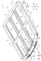
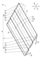
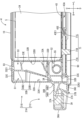
- FIG. 1 is a perspective view of a vehicle according to an embodiment, viewed from the upper left; Exploded perspective view of the cooling structure A perspective view of the housing of the cooling structure seen from the upper left A perspective view of the cooling structure from the upper left Cross-sectional view of the housing (cross-section taken along line V-V in FIG. 3) Cross-sectional view of the housing (cross-section taken along line VI-VI in FIG. 3) FIG. 6 is an enlarged cross-sectional view of the first frame portion and its periphery on the right side in FIG. 5 (showing the state in which the upper panel is attached).
- a battery cooling structure (vehicle battery cooling structure) 4 provided in an automobile (vehicle) 1 will be described.
- Each figure will be described with the arrow direction FR as the forward direction (front of the vehicle), the arrow direction RR as the rearward direction (rear of the vehicle), the arrow direction U as the upward direction, the arrow direction D as the downward direction, the arrow direction L as the leftward direction, and the arrow direction R as the rightward direction.
- the left-right direction may also be referred to as the vehicle width direction (vehicle width direction).
- automobile 1 comprises seats 2, 3 arranged in the passenger compartment, a cooling structure 4 arranged below the seats 2, 3, a plurality of batteries 5 (see FIG. 5) arranged inside the cooling structure 4, and a radiator 6 and a pump 7 connected to the cooling structure 4 via a refrigerant pipe 8 (shown by a dashed line).
- the seats 2, 3 are attached to the upper side of a floor panel (not shown) that constitutes the floor surface of the passenger compartment.
- the cooling structure 4 is attached to the lower side of the floor panel.
- automobile 1 is a right-hand drive vehicle with the steering wheel located on the right side, and of the seats 2, 3, the right seat 2 is the driver's seat and the left seat 3 is the passenger seat.
- the automobile 1 is an electric vehicle, a hybrid vehicle, or the like, that moves using electricity stored in a battery 5.
- the automobile 1 cools the battery 5 with a cooling system that is made up of a cooling structure 4, a radiator 6, and a pump 7 connected by a refrigerant pipe 8.
- a refrigerant (cooling water) such as LLC (Long Life Coolant) circulates in the refrigerant pipe 8.
- the refrigerant that is heated by heat exchange with the battery 5 in the cooling structure 4 circulates in the refrigerant pipe 8 and is cooled by heat exchange with the air outside the passenger compartment that passes through the radiator 6, and is sent back to the cooling structure 4 by driving the pump 7.
- a refrigerant cooling method is merely an example and is not limited to this embodiment.
- the cooling structure 4 has a plate surface 4A that extends in the front-to-rear direction (front-to-rear direction of the vehicle) and the vehicle width direction, and is shaped like a long plate with the long side in the front-to-rear direction as a whole.
- the front portion 4F of the cooling structure 4 has a shape in which the length in the vehicle width direction decreases the further forward it is.
- the cooling structure 4 comprises a housing 11 that is open at the top, and an upper panel 10 that covers the housing 11 from above.
- the upper panel 10 is a metal plate made of a metal such as aluminum, and forms the top surface of the cooling structure 4.
- a floor panel on which the seats 2 and 3 are attached is arranged above the upper panel 10.
- the housing 11 is a structure made of a metal such as aluminum.
- the housing 11 includes a plate-shaped lower panel 90 having the same external shape as the upper panel 10, a support 70 disposed above the lower panel 90, a cooling structure 40 disposed above the support 70, and a frame-shaped frame 20 that forms the skeleton of the housing 11.
- the cooling structure 40 has a cooling section 44 having a plurality of (three) cooling flow paths 41A, 42A, 43A through which the refrigerant flows in a predetermined direction, and has a flow path section 50 arranged on the outer side of the cooling section 44 in the vehicle width direction and connected to the plurality of cooling flow paths 41A, 42A, 43A.
- the cooling section 44 extends in a plane extending in the front-rear and left-right directions, and includes a first cooling section 41, a second cooling section 42, and a third cooling section 43 that are rectangular in top view with the long side extending in the front-rear direction.
- the first cooling section 41 has a tubular shape extending in the front-rear direction inside it and has a plurality of first flow paths 41A aligned in the vehicle width direction.
- the second cooling section 42 is provided to the right (side) of the first cooling section 41.
- the second cooling section 42 has a tubular shape extending in the front-rear direction inside it and has a plurality of second flow paths 42A aligned in the vehicle width direction.
- the second flow paths 42A are arranged to the right of the first flow paths 41A.
- the third cooling section 43 is provided to the right of the second cooling section 42.
- the third cooling section 43 has a tubular shape extending in the front-rear direction inside and includes a plurality of third flow paths 43A arranged in the vehicle width direction.
- the third flow paths 43A are arranged to the right of the second flow paths 42A.
- the flow path section 50 includes a front flow path section 50A that has flow paths connected to the multiple cooling flow paths 41A, 42A, 43A, is arranged on the front side of the cooling section 44, and extends in the vehicle width direction; a rear flow path section 50B that has flow paths connected to the multiple cooling flow paths 41A, 42A, 43A, is arranged on the rear side of the cooling section 44, and extends in the vehicle width direction; and a side flow path section 55 that is arranged on the right side of the cooling section 44 (one of both sides in the vehicle width direction, the driver's seat 2 side), is connected to the right end of the rear flow path section 50B (the right end of the rear third connection section 58), and extends from the front side of the vehicle (front flow path section 50A side) to the rear side of the vehicle (rear flow path section 50B side).
- the flow path section 50 is a tubular body in which a flow path through which the refrigerant passes is formed, and is configured by connecting a plurality of these.
- the front end of the side flow passage section 55 is connected to the radiator 6 via the refrigerant pipe 8 (see FIG. 1), and is connected to an outflow pipe 50D that extends at an angle inward (leftward) in the vehicle width direction as it approaches the front.
- the front flow path section 50A comprises a front first connection section 51 provided in front of the first cooling section 41, extending in the vehicle width direction and having an internal flow path connected to the first flow path 41A, a front second connection section 52 provided in front of the second cooling section 42 to the right of the front first connection section 51 (between the front first connection section 51 and the front third connection section 53), extending in the vehicle width direction and having an internal flow path connected to the second flow path 42A, and a front third connection section 53 provided in front of the third cooling section 43 to the right of the front second connection section 52, extending in the vehicle width direction and having an internal flow path connected to the third flow path 43A.
- the front flow passage 50A is tubular and extends in the vehicle width direction, and includes a front joint 54A that connects the right end of the front first connection 51 and the left end of the front second connection 52, and a front joint 54B that connects the right end of the front second connection 52 and the left end of the front third connection 53.
- the left end of the front first connection 51 is connected to an inlet pipe 50C that is connected to the pump 7 via a refrigerant pipe 8 (see FIG. 1) and extends at an angle inward (right side) in the vehicle width direction as it approaches the front.
- the rear flow path section 50B comprises a rear first connection section 56 provided rearward of the first cooling section 41, extending in the vehicle width direction and having an internal flow path connected to the first flow path 41A, a rear second connection section 57 provided rearward of the second cooling section 42 to the right of the rear first connection section 56 (between the rear first connection section 56 and the rear third connection section 58), extending in the vehicle width direction and having an internal flow path connected to the second flow path 42A, and a rear third connection section 58 provided rearward of the third cooling section 43 to the right of the rear second connection section 57, extending in the vehicle width direction and having an internal flow path connected to the third flow path 43A.
- the rear flow passage section 50B is tubular and extends in the vehicle width direction, and includes a rear joint section 59A that connects the right end of the rear first connection section 56 and the left end of the rear second connection section 57, and a rear joint section 59B that connects the right end of the rear second connection section 57 and the left end of the rear third connection section 58.
- the side flow passage section 55 is a straight pipe that does not have a joint (branched portion) like the joint section described above, and there is no joint in the part of the side flow passage section 55 that is on the outer side of the cooling section 44 in the vehicle width direction.
- the length of the side flow passage section 55 in the front-rear direction is approximately equal to the length of the cooling section 44 in the front-rear direction, and is longer than the length of the front flow passage section 50A in the vehicle width direction and the length of the rear flow passage section 50B in the vehicle width direction.
- the refrigerant flowing in from the inlet pipe 50C flows in the order of the front flow passage section 50A, the cooling section 44, the rear flow passage section 50B, and the side flow passage section 55, and flows out from the outlet pipe 50D.
- the refrigerant flows backward (opposite to the specified direction) RR, and in the side flow passage section 55, the refrigerant flows forward (specified direction) FR.
- the refrigerant flowing through the front flow passage section 50A is partially diverted through the front first connection section 51 into the multiple first flow passages 41A, partially diverted through the front second connection section 52 into the multiple second flow passages 42A, and partially diverted through the front third connection section 53 into the multiple third flow passages 43A.
- the refrigerant flowing rearward through the multiple first flow passages 41A joins at the rear first connection section 56 and flows to the right (rear joint section 59A).
- the refrigerant flowing rearward through the multiple second flow passages 42A joins at the rear second connection section 57 with the refrigerant flowing to the right from the rear first connection section 56 and flows further to the right (rear joint section 59B).
- the refrigerant flowing rearward through the multiple third flow passages 43A joins at the rear third connection section 58 with the refrigerant flowing to the right from the rear second connection section 57 and flows further to the right (side flow passage section 55).
- the refrigerant flow paths are indicated by dashed lines.
- the multiple first flow paths 41A (see Figure 5) provided in the first cooling section 41 are indicated by a single dashed line extending in the fore-and-aft direction at the central portion in the vehicle width direction of the first cooling section 41 (the same applies to the second flow path 42A provided in the second cooling section 42 and the third flow path 43A provided in the third cooling section 43).
- the length of the first path L1 from the front first connection portion 51 to the first flow path 41A, the rear first connection portion 56, the rear joint portion 59A, the rear second connection portion 57, the rear joint portion 59B, the rear third connection portion 58, and the side flow path portion 55 is equal to the length of the second path L2 from the front first connection portion 51 to the front joint portion 54A, the front second connection portion 52, the second flow path 42A, the rear second connection portion 57, the rear joint portion 59B, the rear third connection portion 58, and the side flow path portion 55.
- the lengths of the first path L1 and the second path L2 are equal to the length of the third path L3 that extends from the front first connection portion 51 to the front joint portion 54A, the front second connection portion 52, the front joint portion 54B, the front third connection portion 53, the third flow path 43A, the rear third connection portion 58, and the side flow path portion 55.
- the lengths of the paths L1, L2, and L3 need only be equal to each other.
- the joints 54A, 54B, 59A, and 59B and the side flow path 55 are not essential components of the paths L1, L2, and L3.
- the paths L1, L2, and L3 may be paths that omit the joints 54A, 54B, 59A, and 59B and the side flow path 55.
- the lengths of the paths are equal. For example, in the first path L1, the length of the left path passing through the left flow path 41A1 (see FIG.
- the front first connection part 51 includes a front main pipe part 61 having a circular tube shape extending in the vehicle width direction, and a front connection pipe part 62 connected to the front main pipe part 61, extending in the fore-aft direction, and inclined downward as it approaches the first cooling part 41 side (rear).
- the rear first connection part 56 includes a rear main pipe part 66 having a circular tube shape extending in the vehicle width direction, and a rear connection pipe part 67 connected to the rear main pipe part 66, forming a circular tube extending in the fore-aft direction, and inclined downward as it approaches the first cooling part 41 side (forward).
- FIG. 6 shows a cross section including the right-side flow path 41A3 located at the rightmost position among the plurality of first flow paths 41A and the front connection pipe part 62 connected to the right-side flow path 41A3.
- the front connecting pipe section 62 and the rear connecting pipe section 67 are each integrally formed members.
- the front connecting pipe section 62 and the rear connecting pipe section 67 are provided with a plurality of cylindrical flow paths through which the refrigerant flows.
- the cross-sectional area of the flow path (and thus the first total area described below) can be adjusted by adjusting the hole diameter of the flow path.
- the hole diameter is adjusted in the portion of each of the flow paths provided in the front connecting pipe section 62 and the rear connecting pipe section 67 that has the smallest cross-sectional area and has the greatest effect on pressure loss.
- the first total area described below is adjusted for the front first connecting section 51 and the rear first connecting section 56 without relying on other members.
- the front second connecting section 52 and the rear second connecting section 57, as well as the front third connecting section 53 and the rear third connecting section 58, are also configured in the same manner as the front first connecting section 51 and the rear first connecting section 56.
- the second total area of the front second connection portion 52 and the rear second connection portion 57 is adjusted without relying on other members
- the third total area of the front third connection portion 53 and the rear third connection portion 58 is adjusted without relying on other members.
- the refrigerant flowing through the front main pipe section 61 is divided by the multiple front connecting pipe sections 62 and flows into the multiple first flow paths 41A.
- the refrigerant flowing through the multiple first flow paths 41A passes through the multiple rear connecting pipe sections 67 and flows into the rear main pipe section 66 where it merges.
- each of the flow paths 41A1, 41A2, and 41A3 of the first flow path 41A is surrounded by plate portions on both the top and bottom sides and the left and right sides, and has a rectangular cross section with the longer side extending in the vehicle width direction.
- the cross-sectional shapes of the second flow path 42A and the third flow path 43A may also be similar to the cross-sectional shape of the first flow path 41A.
- the sum of the cross-sectional area of the flow path through which the refrigerant flows at the front first connection part 51 and the cross-sectional area of the flow path through which the refrigerant flows at the rear first connection part 56 is defined as the first total area
- the sum of the cross-sectional area of the flow path through which the refrigerant flows at the front second connection part 52 and the cross-sectional area of the flow path through which the refrigerant flows at the rear second connection part 57 is defined as the second total area
- the sum of the cross-sectional area of the flow path through which the refrigerant flows at the front third connection part 53 and the cross-sectional area of the flow path through which the refrigerant flows at the rear third connection part 58 is defined as the third total area.
- the first total area is different from the second total area.
- the first total area and the second total area are determined so that the difference between the pressure loss of the refrigerant flowing through the first path L1 and the pressure loss of the refrigerant flowing through the second path L2 is smaller than when the first total area and the second total area are equal.
- the third total area is different from the second total area. The third total area and the second total area are set so that the difference between the pressure loss of the refrigerant flowing through the third path L3 and the pressure loss of the refrigerant flowing through the second path L2 is smaller than when the third total area and the second total area are equal.
- the first total area and the third total area are set so that the difference between the pressure loss of the refrigerant flowing through the first path L1 and the pressure loss of the refrigerant flowing through the third path L3 is smaller.
- the first total area is smaller than the second total area.
- the first total area may be equal to the third total area, or may be adjusted to a cross-sectional area different from each other to reduce the difference in pressure loss.
- the second total area is larger than both the first total area and the third total area.
- the cross-sectional area of the flow passages (total area) is adjusted by adjusting the hole diameter of the flow passages drilled in each connecting pipe section as described above, so the cross-sectional areas of the multiple cooling flow passages 41A, 42A, 43A are uniform with each other. Also, the hole diameter of each flow passage in the cooling flow passages 41A, 42A, 43A is larger than the hole diameter of the flow passages drilled in each connecting pipe section.
- the frame 20 is disposed so as to surround the cooling section 44, and divides the upper surface of the cooling section 44 into six regions A1 to A6.
- the frame 20 is provided with two columnar first frame portions 21, 22 disposed on both sides of the cooling section 44 in the vehicle width direction (outside in the vehicle width direction) and extending in the front-rear direction, two columnar second frame portions 23, 24 disposed on both sides of the cooling section 44 in the front-rear direction and extending in the vehicle width direction, two columnar third frame portions 25, 26 extending in the front-rear direction between the two second frame portions 23, 24, and a columnar fourth frame portion 27 extending in the vehicle width direction between the two first frame portions 21, 22.
- a plurality of rectangular batteries 5 (see Figures 5 and 6) with their long sides aligned in the vehicle width direction are arranged in a row in the front-to-rear direction.
- the configuration of the batteries 5 is not particularly limited, but secondary batteries such as lead-acid batteries and lithium-ion batteries can be used.
- the first frame part 21 on the right side (driver's seat 2 side) of the two first frame parts 21, 22 is housed inside (inside the frame main body 21A) with the side flow passage part 55.
- the first frame part 21 on the right side is a frame main body 21A extending in the front-rear direction, and has a cross section (called an axial cross section, the same applies below) perpendicular to the axial direction along which it extends that is L-shaped as a whole.
- the frame main body 21A has a main body part 21B whose axial cross section is generally rectangular with the long sides extending in the up-down direction as a whole, and a protruding part 21C protruding from the lower right end of the main body part 21B to the outside (right) in the vehicle width direction.
- the first frame part 22 on the left side is symmetrical to the first frame part 21 on the right side, except that the side flow passage part 55 is not housed inside.
- the first frame part 22 on the left side has a frame main body 22A having a main body part 22B and a protruding part 21C.
- the main body 21B includes a first outer wall portion (outer wall portion) 32A having a plate shape extending in the vertical and longitudinal directions, and a first inner wall portion (inner wall portion) 32B having a plate shape extending in the vertical and longitudinal directions, facing the battery 5, and disposed on the vehicle width direction inner side (vehicle inner side) than the first outer wall portion 32A.
- the main body 21B also includes a first upper wall portion (upper wall portion) 32C having a plate shape extending in the vertical and longitudinal directions and connecting the upper end of the first outer wall portion 32A and the upper end of the first inner wall portion 32B, and a first lower wall portion 32D having a plate shape extending in the vertical and longitudinal directions and extending from the lower end of the lower portion 32A3 of the first outer wall portion 32A to the vehicle width direction inner side (left side).
- the first outer wall portion 32A extends downwardly from the first inner wall portion 32B.
- a plate-shaped first inclined portion (inclined portion) 33A is provided connecting the inner surface 32A1 of the first outer wall portion 32A and the inner surface 32B1 of the first inner wall portion 32B.
- a side flow passage portion 55 is arranged below the first inclined portion 33A.
- the first inclined portion 33A extends at an incline upward (in a direction moving away from the side flow passage portion 55 in the height direction) from the first outer wall portion 32A side (outside in the vehicle width direction: outside the vehicle) toward the first inner wall portion 32B side (inside in the vehicle width direction).
- the first inclined portion 33A is arranged below the center portion in the up-down direction of the main body 21B.
- the portion where the first outer wall portion 32A and the first inclined portion 33A are connected is called the connecting portion 34.
- a plate-shaped first intermediate wall portion 33B connecting the upper surface of the first inclined portion 33A and the lower surface of the first upper wall portion 32C
- a plate-shaped second intermediate wall portion 33C connecting the lower surface of the first inclined portion 33A and the left end portion of the first lower wall portion 32D
- a plate-shaped third intermediate wall portion 33D connecting the lower surface of the first inclined portion 33A and the inner surface 32B1 of the first inner wall portion 32B
- a plate-shaped fourth intermediate wall portion 33E connecting the inner surface of the first intermediate wall portion 33B and the inner surface 32B1 of the first inner wall portion 32B.
- the first intermediate wall portion 33B extends from the first outer wall portion 32A toward the first inner wall portion 32B in an axial cross section, inclining upward, and includes a lower wall portion 33B1 connecting the first inclined portion 33A and the right end of the fourth intermediate wall portion 33E, and an upper wall portion 33B2 extending in the vertical direction and connecting the upper end of the lower wall portion 33B1 and the first upper wall portion 32C.
- the first intermediate wall portion 33B is bent at a portion between the lower wall portion 33B1 and the upper wall portion 33B2, and the right end of the fourth intermediate wall portion 33E is connected to this bent portion.
- the portion surrounded by the first outer wall portion 32A, the first inclined portion 33A, the first intermediate wall portion 33B, and the first upper wall portion 32C is called a hollow portion S1.
- the hollow portion S1 is located at the upper right of the side flow passage portion 55, and expands on both sides in the vehicle width direction as it moves upward.
- the hollow portion S1 is a portion that does not have a wall portion extending in the vehicle width direction that connects the first outer wall portion 32A and the first intermediate wall portion 33B (does not have a middle rib extending in the inside-outside direction of the vehicle).
- the second intermediate wall portion 33C is connected to the first inclined portion 33A at a position where its upper end is more inward in the vehicle width direction than the lower end of the first intermediate wall portion 33B.
- the third intermediate wall portion 33D is located more inward in the vehicle width direction than the first intermediate wall portion 33B and the second intermediate wall portion 33C, and extends with a downward inclination toward the first inner wall portion 32B.
- the portion surrounded by the second intermediate wall portion 33C, the first inclined portion 33A, the third intermediate wall portion 33D, the first inner wall portion 32B, and the base portion 71A of the side support portion 71 described later is the storage portion S2.
- the side flow path portion 55 is stored in the storage portion S2.
- the fourth intermediate wall portion 33E extends in a slightly upward inclined manner toward the first inner wall portion 32B.
- the portion surrounded by the first inner wall portion 32B, the first upper wall portion 32C, the upper wall portion 33B2 of the first intermediate wall portion 33B, and the fourth intermediate wall portion 33E is the receiving portion S3.
- the first upper wall portion 32C has a first mounting portion (mounting portion) 32C1 to which the upper panel 10 covering the cooling portion 44 and the battery 5 is attached by a mounting member such as a screw 93.
- the first mounting portion 32C1 is a hole that penetrates in the vertical direction and is provided at a position in the vehicle width direction between the first outer wall portion 32A and the first inner wall portion 32B (and further between the upper wall portion 33B2 of the first intermediate wall portion 33B and the first inner wall portion 32B).
- the first mounting portion 32C1 is connected to the receiving portion S3.
- the tip (lower end) of the screw 93 is inserted into the receiving portion S3.
- the protrusion 21C includes a second outer wall portion 36A having a plate shape extending in the vertical and longitudinal directions, a second upper wall portion 36B having a plate shape extending in the longitudinal direction and connecting the upper end of the second outer wall portion 36A to the first outer wall portion 32A (more specifically, connecting the upper end of the second outer wall portion 36A to the connecting portion 34), and a second lower wall portion 36C located below the second upper wall portion 36B and extending from the lower end of the lower portion 32A3 of the first outer wall portion 32A to the outside (right) in the vehicle width direction.
- the protrusion 21C also includes a second mounting portion 39 that vertically penetrates the second upper wall portion 36B and the sixth intermediate wall portion 37C.
- the second mounting portion 39 is attached to a side sill or the like (not shown) that constitutes the framework of the automobile 1 via a mounting member such as a bolt.
- a plate-shaped second inclined portion (inclined portion) 37A is provided that connects the lower surface of the upper wall main body portion 36B1 of the second upper wall portion 36B and the outer surface of the lower portion 32A3 of the first outer wall portion 32A.
- the second inclined portion 37A extends at an incline downward (in a direction away from the side flow passage portion 55) from the second outer wall portion 36A side (outside in the vehicle width direction) toward the lower portion 32A3 side (inside in the vehicle width direction) of the first outer wall portion 32A.
- the side flow passage portion 55 does not exist on the extension line of the second inclined portion 37A, in the event of a collision from the outside of the automobile 1, the force applied to the frame main body 21A due to the collision can be transmitted through the second inclined portion 37A so as to avoid the side flow passage portion 55.
- the second upper wall portion 36B includes an upper wall main body portion 36B1 extending in the vehicle width direction, and a third inclined portion (inclined portion) 36B2 located to the left of the upper wall main body portion 36B1 (inner side in the vehicle width direction) and connected to the connecting portion 34.
- a side flow path portion 55 is arranged on the extension line of the upper wall main body portion 36B1 on the inner side in the vehicle width direction.
- the third inclined portion 36B2 extends at an incline upward (in the direction away from the side flow path portion 55) from the upper wall main body portion 36B1 side (outer side in the vehicle width direction) toward the connecting portion 34 side (inner side in the vehicle width direction).
- the angle with respect to the horizontal plane is equal to the angle with respect to the horizontal plane in the first inclined portion 33A.
- the first inclined portion 33A is located on the inner side in the vehicle width direction of the third inclined portion 36B2 and on the extension line of the third inclined portion 36B2.
- the distance between the first inclined portion 33A and the third inclined portion 36B2 and the second inclined portion 37A increases toward the inside in the vehicle width direction.
- the side flow passage portion 55 is provided between the first inclined portion 33A and the third inclined portion 36B2 and the second inclined portion 37A.
- a plate-shaped fifth intermediate wall portion 37B that connects the lower surface of the second inclined portion 37A to the right end of the second lower wall portion 36C, and a sixth intermediate wall portion 37C that connects the outer surface of the fifth intermediate wall portion 37B to the inner surface of the second outer wall portion 36A.
- the fifth intermediate wall portion 37B extends in a manner that is inclined outward in the vehicle width direction as it extends downward.
- the sixth intermediate wall portion 37C extends horizontally.
- the front second frame portion 23 comprises a central portion 23A, a right side portion 23B that is connected to the central portion 23A and the right first frame portion 21 and extends with a slight rearward incline as it approaches the right, and a left side portion 23C that is connected to the central portion 23A and the left first frame portion 22 and extends with a slight rearward incline as it approaches the left.
- An inlet pipe 50C is housed inside the left side portion 23C.
- An outlet pipe 50D is housed inside the right side portion 23B.
- a rear flow passage portion 50B is housed inside the rear second frame portion 24.
- the left third frame portion 25 has a plate-shaped base portion 25A extending in the front-rear direction and the vehicle width direction, and a rising portion 25B rising upward from the center of the base portion 25A in the vehicle width direction, and has an inverted T-shaped cross section in the axial direction as a whole.
- the battery 5 is attached to the base portion 25A via a mounting member such as a bolt.
- the lower surface of the base portion 25A faces the lower panel 90.
- the left and right ends of the base portion 25A are fitted into the right end of the first cooling portion 41 and the left end of the second cooling portion 42, so that the left third frame portion 25 connects the first cooling portion 41 and the second cooling portion 42 in the vehicle width direction.
- the right third frame portion 26 is configured similarly to the left third frame portion 25, and connects the second cooling portion 42 and the third cooling portion 43 in the vehicle width direction.
- the front end 25E of the third frame portion 25 on the left side is provided with a frame opening 25E1 that opens in the vehicle width direction.
- the front joint portion 54A of the front flow passage portion 50A penetrates the frame opening 25E1 in the vehicle width direction.
- the front end 26E of the third frame portion 26 on the right side is provided with a frame opening 26E1 that opens in the vehicle width direction.
- the front joint portion 54B of the front flow passage portion 50A penetrates the frame opening 26E1 in the vehicle width direction.
- the fourth frame portion 27 intersects with the two third frame portions 25 and 26.
- the support 70 has two plate-shaped side support parts (first intermediate parts) 71 arranged on both sides in the vehicle width direction, and a plate-shaped front support part (second intermediate part) 72 arranged in front of the two side support parts 71.
- the two side support parts 71 are interposed between the cooling part 44 and the frame main bodies 21A, 22A of the two first frame parts 21, 22, respectively, and are interposed parts that do not have a flow path through which the refrigerant flows.
- the left side support part 71 is disposed on the outer side of the first cooling part 41 in the vehicle width direction, and extends in the front-rear direction along the side plate part 41D which serves as the left end part (end part in the vehicle width direction) of the first cooling part 41.
- the right side support part 71 is disposed on the outer side of the third cooling part 43 in the vehicle width direction, and extends in the front-rear direction along the side plate part 43E which serves as the right end part (end part in the vehicle width direction) of the third cooling part 43.
- the right side support part 71 comprises a plate-shaped base part 71A, a fourth mounting part 71B that is arranged in the center of the base part 71A in the vehicle width direction and to which the battery 5 is attached via a mounting member such as a bolt, and a recessed part 71C that is arranged on the inside of the base part 71A in the vehicle width direction.
- a side flow passage part 55 is arranged on the upper right side of the base part 71A.
- the lower surface of the fourth mounting part 71B faces the lower panel 90.
- the recessed part 71C fits into a protrusion part 43E1 that protrudes outward in the vehicle width direction from the right side plate part 43E of the third cooling part 43.
- the left side support part 71 is configured symmetrically to the right side support part 71.
- the left third frame portion 25 has an extension portion 25E2 at its front end portion 25E that extends forward (outside in the vehicle's fore-and-aft direction) further forward than the first cooling portion 41.
- the front support portion 72 is located between the cooling portion 44 and the second frame portion 23 and below the extension portion 25E2 (and the extension portion in the right third frame portion 26), and is an intermediate portion that does not have a flow path through which the refrigerant flows.
- the front support portion 72 has a plate portion 72B having a configuration similar to the base portion 71A and the fourth mounting portion 71B of the side support portion 71.
- the rear end portion 72B1 of the plate portion 72B is fitted into each of the connection portions 51, 52, and 53 of the front flow path portion 50A.
- a cooling structure 4 that includes a cooling section 44 on which a battery 5 is placed, the cooling section 44 having cooling flow paths 41A, 42A, 43A through which the refrigerant flows in a predetermined direction, a front flow path section 50A having flow paths connected to the cooling flow paths 41A, 42A, 43A and disposed on the front side of the vehicle of the cooling section 44, a rear flow path section 50B having flow paths connected to the cooling flow paths 41A, 42A, 43A and disposed on the rear side of the vehicle of the cooling section 44, and a side flow path section 55 that is disposed on one of both sides in the vehicle width direction of the cooling section 44, connects to the rear flow path section 50B, and extends from the front side of the vehicle to the rear side of the vehicle, and in the side flow path section 55, the refrigerant flows in the opposite direction to the predetermined direction.
- the refrigerant that flows from the front flow passage section 50A through the cooling flow passages 41A, 42A, 43A of the cooling section 44 in a predetermined direction to the rear flow passage section 50B can be returned to the front flow passage section 50A side by flowing in the opposite direction to the predetermined direction in the side flow passage section 55 arranged on one of the two sides (right side) of the cooling section 44 in the vehicle width direction.
- the side flow passage section 55 is located on either side of the cooling section 44 in the vehicle width direction, on the driver's seat 2 side of the vehicle.
- the cooling structure 4 is provided with two first frame sections 21, 22 arranged on both sides of the cooling section 44 in the vehicle width direction and extending in the fore-and-aft direction of the vehicle, and the side flow passage section 55 is housed inside the first frame section 21, which is one of the two first frame sections 21, 22.
- the side flow passage section 55 can be protected from a side impact by one of the two first frame sections 21, 22, the first frame section 21.
- the two first frame sections 21, 22 can protect the cooling section 44 and the battery 5 from a side impact.
- the length of the first path L1 from the front first connection part 51 to the first flow path 41A, the rear first connection part 56, the rear second connection part 57, and the side flow path part 55 is equal to the length of the second path L2 from the front first connection part 51 to the front second connection part 52, the second flow path 42A, the rear second connection part 57, and the side flow path part 55.
- the difference in pressure loss occurring in the first flow path 41A and the second flow path 42A can be reduced by making the length of the first path L1 equal to the length of the second path L2. This makes it possible to prevent the occurrence of parts with different temperatures in the cooling part 44, and to evenly cool the batteries 5 placed on the cooling part 44, even if the cooling part 44 has multiple flow paths (first flow path 41A and second flow path 42A).
- the first total area which is the sum of the cross-sectional area of the flow path through which the refrigerant flows at the front first connection part 51 and the cross-sectional area of the flow path through which the refrigerant flows at the rear first connection part 56, is different from the second total area, which is the sum of the cross-sectional area of the flow path through which the refrigerant flows at the front second connection part 52 and the cross-sectional area of the flow path through which the refrigerant flows at the rear second connection part 57, and the first total area and the second total area are set so that the difference between the pressure loss of the refrigerant flowing through the first path L1 and the pressure loss of the refrigerant flowing through the second path L2 is smaller than when the first total area and the second total area are equal.
- the difference in pressure loss that occurs in the first path L1 and the second path L2 can be reduced due to the structure of the front first connection part 51. This allows the battery 5 placed on the cooling part 44 to be cooled more evenly.
- the cooling structure 4 is provided with two second frame parts 23, 24 arranged on both sides of the cooling section 44 in the vehicle longitudinal direction and extending in the vehicle width direction, and third frame parts 25, 26 extending in the vehicle longitudinal direction between the two second frame parts 23, 24, and the front flow passage part 50A penetrates the third frame parts 25, 26 in the vehicle width direction.
- the third frame parts 25, 26 can protect the front flow passage part 50A from collisions with the vehicle.
- the two second frame parts 23, 24 can protect the cooling part 44 and the battery 5 from collisions from the front and rear of the vehicle.
- the cooling section 44 has cooling flow paths 41A, 42A, 43A that extend in the fore-and-aft direction of the vehicle and a third flow path 43A arranged to the side of the second flow path 42A, the front flow path section 50A has a front third connection section 53 connected to the third flow path 43A, the rear flow path section 50B has a rear third connection section 58 connected to the third flow path 43A, the front second connection section 52 is provided between the front first connection section 51 and the front third connection section 53, and the second total area is larger than the first total area or a third total area that is the sum of the cross-sectional area of the flow path through which the refrigerant flows at the front third connection section 53 and the cross-sectional area of the flow path through which the refrigerant flows at the rear third connection section 58.
- the pressure loss in the path (second path L2) including the flow path (second flow path 42A) located in the center of the multiple flow paths may be greater than the pressure loss in the path (first path L1 or third path) including the flow path (first flow path 41A or third flow path 43A) provided on the side of it.
- the cooling structure 4 since the second total area is greater than the first total area or the third total area, the difference between the pressure loss in the second path L2 and the pressure loss in the first path L1 or the third path can be reduced. This prevents the occurrence of parts with different temperatures in the cooling section 44, and allows the batteries 5 placed on the cooling section 44 to be evenly cooled.
- the cooling section 44 includes a first cooling section 41 having a first flow path 41A and a second cooling section 42 having a second flow path 42A and provided to the side of the first cooling section 41, and the third frame section 25 is configured to connect the first cooling section 41 and the second cooling section 42 in the vehicle width direction.
- the third frame portion 25 that protects the front flow passage portion 50A can also function as connecting the first cooling portion 41 and the second cooling portion 42 in the vehicle width direction. This makes it possible to reduce the number of components and ensure the space for mounting the battery 5.
- a cooling structure 4 that includes a flow path section 50 that is arranged on the outer side of the cooling section 44 in the vehicle width direction and connects to the cooling flow paths 41A, 42A, and 43A, and a frame 20 that is arranged to surround the cooling section 44, the frame 20 houses the flow path section 50 inside its frame body 21A, and the frame body 21A includes inclined sections 33A, 36B2, and 37A that extend in an axial cross section at an angle away from the flow path section 50 in the height direction as they move from the outer side in the vehicle width direction toward the inner side in the vehicle width direction.
- the cooling structure 4 has intervening parts 71, 72 that are interposed between the cooling part 44 and the frame main body 21A and do not have a flow path through which the refrigerant flows.
- the force applied to the frame main body 21A due to a collision can be buffered by being transmitted to the intervening parts 71, 72 (and further transmitted from the intervening parts 71, 72 to the cooling part 44). This makes it difficult for the force of the collision to be directly transmitted to the battery 5 placed on the cooling part 44.
- the intervening parts 71, 72 do not have a flow path through which the refrigerant flows, no flow path malfunction occurs in the intervening parts 71, 72 during a collision.
- the frame body 21A has a hollow section S1 above the flow passage section 50 that does not have a center rib extending in the inside/outside direction of the vehicle.
- the hollow portion S1 does not have any portion that extends in the inside or outside direction of the vehicle, so the force transmitted from the outside of the hollow portion S1 in the vehicle width direction during a collision is unlikely to be directly transmitted to the inside of the hollow portion S1 in the vehicle width direction. If the battery 5 is arranged on the inside of the hollow portion S1 in the vehicle width direction, it will be easier to protect the battery 5 from a collision.
- the intervening portions 71, 72 are interposed between the cooling portion 44 and the first frame portions 21, 22, extend in the fore-and-aft direction of the vehicle along the ends 41D, 43E on both sides of the cooling portion 44 in the vehicle width direction, and include a first intervening portion 71 that does not have a flow path through which the refrigerant flows.
- the first frame parts 21, 22 can protect the cooling part 44 from side collisions. Furthermore, the force applied laterally to the first frame parts 21, 22 due to a side collision can be transmitted to the first intermediate part 71 (and further transmitted from the first intermediate part 71 to the cooling part 44) and buffered. This makes it difficult for the force of a side collision to be directly transmitted to the battery 5 placed on the cooling part 44. Furthermore, because the first intermediate part 71 does not have a flow path through which the refrigerant flows, no flow path malfunction occurs in the first intermediate part 71 during a side collision.
- the third frame portion 25 has an extension portion 25E2 that extends further outward in the fore-and-aft direction of the vehicle than the cooling portion 44, and the intervening portions 71, 72 include a second intervening portion 72 that is located between the cooling portion 44 and the second frame portions 23, 24 and below the extension portion 25E2.
- the third frame parts 25, 26 that protect the cooling part 44 and the battery 5 connect the first cooling part 41 and the second cooling part 42 in the vehicle width direction, while transmitting the force applied to the second frame parts 23, 24 due to a collision from the front-to-rear direction of the vehicle to the second intermediate part 72 located below the extension part 25E2 (and further from the second intermediate part 72 to the cooling part 44), thereby cushioning the force. Furthermore, the force during a collision from the front-to-rear direction of the vehicle is unlikely to be directly transmitted to the battery 5 placed on the cooling part 44.
- the frame body 21A comprises a first outer wall portion 32A, a first inner wall portion 32B disposed on the inside of the first outer wall portion 32A in the vehicle width direction, and a first upper wall portion 32C connecting the upper portion of the first outer wall portion 32A and the upper portion of the first inner wall portion 32B.
- the first upper wall portion 32C has an attachment portion to which an upper panel 10 that covers the cooling portion 44 is attached, and which is located between the first outer wall portion 32A and the first inner wall portion 32B.
- the direction in which the refrigerant flows in the side flow passage section and the cooling section may be opposite to that of the above embodiment.
- the refrigerant may flow backward in the side flow passage section and forward in the cooling section.
- the number of cooling passages is not particularly limited.
- a fourth passage, a fifth passage, etc., having a configuration similar to that of the first passage, may be arranged side by side in the vehicle width direction.
- At least one of the first inclined portion, the second inclined portion, and the third inclined portion may be disposed inside the frame body as the inclined portion.
- the first inclined portion may be disposed inside the frame body as the inclined portion, or only the first inclined portion and the second inclined portion may be disposed as the inclined portion.
- the driver's seat is provided on the right side of the vehicle's width direction, but this is not limited to this.
- the driver's seat may be provided on the left side of the vehicle's width direction.
- the side flow path portion is housed inside the frame body of the first frame portion on the left side.
- the vehicle battery cooling structure illustrated in the above embodiment is not limited to use in vehicles, and may be provided in various types of vehicles.
- the vehicle battery cooling structure may be applied to ground vehicles such as trains and recreational vehicles.
Landscapes
- Engineering & Computer Science (AREA)
- Chemical & Material Sciences (AREA)
- Combustion & Propulsion (AREA)
- Transportation (AREA)
- Mechanical Engineering (AREA)
- Cooling, Air Intake And Gas Exhaust, And Fuel Tank Arrangements In Propulsion Units (AREA)
Abstract
冷媒が所定方向に流れる冷却流路を有し、電池5が載せられる冷却部44と、冷却部44の乗物前方側に配された前側流路部50Aと、冷却部44の乗物後方側に配された後側流路部50Bと、を備え、冷却部44は、第1流路41Aと、第1流路41Aの側方に配された第2流路42Aと、を少なくとも備え、前側流路部50Aは、第1流路41Aに接続した前側第1接続部51と、第2流路42Aに接続した前側第2接続部52と、を備え、後側流路部50Bは、第1流路41Aに接続した後側第1接続部56と、第2流路42Aに接続した後側第2接続部57と、を備え、前側第1接続部51から、第1流路41A、後側第1接続部56、及び後側第2接続部57に至る第1経路L1の長さは、前側第1接続部51から、前側第2接続部52、第2流路42A、及び後側第2接続部57に至る第2経路L2の長さと等しい、冷却構造4。
Description
本開示は、乗物用電池冷却構造に関する。
従来、乗物用電池冷却構造として、特許文献1に記載の技術が知られている。具体的に、特許文献1には、複数の電池セル(電池)の底面側に配置された長板状のプレート本体と、プレート本体に冷却液(冷媒)を流入させる流入管と、プレート本体から冷却液を流出させる流出管と、を有する冷却プレートを備え、プレート本体の内部を流れる冷却液との熱交換によって各電池を底面側から冷却する、冷却装置が開示されている。プレート本体は、電池の長手方向(プレート本体の短辺方向)に延出し、内部に冷却液が流通する冷却液配管を有する。冷却液配管は、一端部が流入管に連通するとともに他端部が流出管に連通しており、プレート本体の長辺方向に複数本並んでいる。
しかしながら、特許文献1に開示の構成のように、プレート本体において冷媒が流れる流路が複数設けられる場合、それぞれの流路によって異なる圧力損失が生じる可能性がある。すると、プレート本体において温度が異なる部分が生じ、プレート本体に配置された電池を均等に冷却し難くなる。
本開示は上記のような事情に基づいて完成された技術であって、電池を均等に冷却できる乗物用電池冷却構造を提供することを目的とする。
本開示は、冷媒が所定方向に流れる冷却流路を有し、電池が載せられる冷却部と、前記冷却流路に接続する流路を有し、前記冷却部の乗物前方側に配された前側流路部と、前記冷却流路に接続する流路を有し、前記冷却部の乗物後方側に配された後側流路部と、を備え、前記冷却部は、前記冷却流路として、乗物前後方向に延びた第1流路と、乗物前後方向に延び、前記第1流路の側方に配された第2流路と、を少なくとも備え、前記前側流路部は、前記第1流路に接続した前側第1接続部と、前記第2流路に接続した前側第2接続部と、を備え、前記後側流路部は、前記第1流路に接続した後側第1接続部と、前記第2流路に接続した後側第2接続部と、を備え、前記前側第1接続部から、前記第1流路、前記後側第1接続部、及び前記後側第2接続部に至る第1経路の長さは、前記前側第1接続部から、前記前側第2接続部、前記第2流路、及び前記後側第2接続部に至る第2経路の長さと等しい、乗物用電池冷却構造である。
このような乗物用電池冷却構造によると、第1経路の長さと第2経路の長さを等しくすることで、第1流路及び第2流路に生じる圧力損失の差を小さくすることができる。これにより、冷却部に複数の流路(第1流路、及び第2流路)が設けられていた場合でも、冷却部において温度が異なる部分が生じることを抑制し、冷却部に載せられた電池を均等に冷却することができる。
上記構成において、前記前側第1接続部において冷媒が流れる流路の断面積と前記後側第1接続部において冷媒が流れる流路の断面積の合計である第1合計面積は、前記前側第2接続部において冷媒が流れる流路の断面積と前記後側第2接続部において冷媒が流れる流路の断面積の合計である第2合計面積と異なり、前記第1合計面積および前記第2合計面積は、前記第1経路を流れる冷媒の圧力損失と前記第2経路を流れる冷媒の圧力損失との差が小さくなるように定められていてもよい。
このような乗物用電池冷却構造によると、第1接続部の構造により第1経路及び第2経路に生じる圧力損失の差を小さくすることができる。これにより、冷却部に載せられた電池の冷却をより均等に行うことができる。尚、仮に第1接続部において複数の流路が設けられている場合は、「流路の断面積」とは、当該複数の流路の合計の断面積を指すこととしてもよい。
上記構成において、前記冷却部は、前記冷却流路として、乗物前後方向に延び、前記第2流路の前記側方に配された第3流路を備え、前記前側流路部は、前記第3流路に接続した前側第3接続部を備え、前記後側流路部は、前記第3流路に接続した後側第3接続部を備え、前記前側第2接続部は、前記前側第1接続部と前記前側第3接続部との間に設けられており、前記第2合計面積は、前記第1合計面積、又は、前記前側第3接続部において冷媒が流れる流路の断面積と前記後側第3接続部において冷媒が流れる流路の断面積の合計である第3合計面積よりも大きいこととしてもよい。
一つの流路(前側流路部)が複数の流路(第1流路、第2流路及び第3流路)に分岐し、再び一つの流路(後側流路部)に合流する場合、複数の流路のうち中央に位置する流路(第2流路)を含む経路(第2経路)における圧力損失は、その側方に設けられた流路(第1流路又は第3流路)を含む経路(第1経路又は第3経路)における圧力損失よりも大きくなることがある。しかしながら、上記のような乗物用電池冷却構造によると、第2合計面積は、第1合計面積、又は、第3合計面積よりも大きいので、第2経路における圧力損失と第1経路又は第3経路における圧力損失との差を小さくすることができる。これにより、冷却部において温度が異なる部分が生じることを抑制し、冷却部に載せられた電池を均等に冷却することができる。
上記構成において、前記前側第1接続部と前記後側第1接続部の少なくとも一方では、他の部材によることなく前記第1合計面積が調整され、前記前側第2接続部と前記後側第2接続部の少なくとも一方では、他の部材によることなく前記第2合計面積が調整され、前記前側第3接続部と前記後側第3接続部の少なくとも一方では、他の部材によることなく前記第3合計面積が調整されていてもよい。
このような構成によると、部材の数を抑えた乗物用電池冷却構造を提供することができる。
上記乗物用電池冷却構造は、前記冷却部の乗物幅方向両側のうち一方側に配され、前記前側流路部と前記後側流路部の少なくとも一方に接続し、前記乗物前方側から前記乗物後方側に延びた側方流路部を備え、前記側方流路部において、冷媒が前記所定方向とは反対方向に流れていてもよい。
このような乗物用電池冷却構造によると、例えば前側流路部から冷却部の冷却流路を所定方向に通って後側流路部に流れる冷媒が、冷却部の乗物幅方向両側のうち一方側に配された側方流路部において所定方向とは反対方向に流れることで、この冷媒を前側流路部側に戻すことができる。これにより、冷却部の乗物幅方向両側のうち他方側に冷媒の流路を設ける必要が無く、他方側からの衝突によって例えば冷媒が漏れるといった影響を抑制することができる。
上記乗物用電池冷却構造は、前記冷却部の乗物幅方向両側に配され、乗物前後方向に延びた2つの第1フレーム部を備え、前記側方流路部は、前記2つの第1フレーム部のうち一方の内部に収容されていてもよい。
このような乗物用電池冷却構造によると、2つの第1フレーム部のうちの一方によって側方流路部を側方からの衝突(側突)から保護することができる。また、2つの第1フレーム部によって側突から冷却部や電池を保護することができる。
上記構成において、前記側方流路部のうち前記冷却部よりも乗物幅方向外側にある部分には、継手が存在していなくてもよい。
このような乗物用電池冷却構造によると、第1流路及び第2流路を繋ぎ、各流路に冷媒を流すような継手を冷却部の側方に設ける必要がなく、側突によって例えば冷媒が漏れるといった影響を一層抑制することができる。
上記乗物用電池冷却構造は、前記冷却部の乗物前後方向両側に配され、乗物幅方向に延びた2つの第2フレーム部と、前記2つの第2フレーム部の間において、乗物前後方向に延びた第3フレーム部と、を備え、前記前側流路部は、前記第3フレーム部を乗物幅方向に貫通していてもよい。
このような乗物用電池冷却構造によると、第3フレーム部によって乗物の衝突から前側流路部を保護することができる。また、2つの第2フレーム部によって乗物の前後側からの衝突に対し冷却部や電池を保護することができる。
上記構成において、前記冷却部は、前記第1流路を有する第1冷却部と、前記第2流路を有し、前記第1冷却部の前記側方に設けられた第2冷却部と、を備え、前記第3フレーム部は、前記第1冷却部と前記第2冷却部とを乗物幅方向に繋ぐ構成とされていてもよい。
このような乗物用電池冷却構造によると、前側流路部を保護する第3フレーム部が、第1冷却部と第2冷却部とを乗物幅方向に繋ぐ機能を兼用することができる。これにより、部材の数を抑えて電池の載置スペースを確保することができる。
本開示によれば、電池を均等に冷却できる乗物用電池冷却構造を提供することが可能となる。
<実施形態>
本開示の実施形態を図1から図7によって説明する。本実施形態では、自動車(乗物)1に設けられる電池の冷却構造(乗物用電池冷却構造)4を説明する。尚、矢印方向FRを前方(乗物前方)、矢印方向RRを後方(乗物後方)、矢印方向Uを上方、矢印方向Dを下方、矢印方向Lを左方、矢印方向Rを右方として各図を説明する。また、左右方向は、車幅方向(乗物幅方向)と呼ぶこともある。
本開示の実施形態を図1から図7によって説明する。本実施形態では、自動車(乗物)1に設けられる電池の冷却構造(乗物用電池冷却構造)4を説明する。尚、矢印方向FRを前方(乗物前方)、矢印方向RRを後方(乗物後方)、矢印方向Uを上方、矢印方向Dを下方、矢印方向Lを左方、矢印方向Rを右方として各図を説明する。また、左右方向は、車幅方向(乗物幅方向)と呼ぶこともある。
図1に示すように、自動車1は、車室内に配された座席2,3と、座席2,3の下方に配された冷却構造4と、冷却構造4の内部に配された複数の電池5(図5参照)と、冷却構造4に対し冷媒管8(一点鎖線で示す)を介して接続されたラジエータ6及びポンプ7と、を備える。座席2,3は、車室の床面を構成するフロアパネル(不図示)の上面側に取り付けられている。冷却構造4は、フロアパネルの下面側に取り付けられている。本実施形態では、自動車1は、右側にハンドルが位置する右ハンドル車とし、座席2,3のうち、右側の座席2を運転席とし、左側の座席3を助手席とする。
自動車1は、電気自動車やハイブリッド車等、電池5に貯められた電気を使用して移動する車とされる。自動車1は、冷却構造4、ラジエータ6、及びポンプ7が冷媒管8によって接続されてなる冷却システムによって、電池5を冷却する。冷媒管8内には、例えば、LLC(Long Life Coolant)等の冷媒(冷却水)が循環している。冷却構造4において電池5と熱交換して温められた冷媒は、冷媒管8内を循環し、ラジエータ6を通過する車室外側の空気と熱交換することで冷却され、ポンプ7の駆動により再び冷却構造4へと送られる。尚、このような冷媒の冷却方法は、一例であり、本実施形態に限定されない。
冷却構造4は、板面4Aが前後方向(乗物前後方向)及び車幅方向に広がり、全体として前後方向を長辺とする長板状をなしている。冷却構造4の前側部分4Fは、前方に向かうほど車幅方向の長さが小さくなる形をなしている。図2及び図3に示すように、冷却構造4は、上方が開口した筐体11と、筐体11を上方から塞ぐアッパーパネル10と、を備える。アッパーパネル10は、アルミニウム等の金属からなる板金とされ、冷却構造4の上面を構成している。アッパーパネル10の上方には、座席2,3が取り付けられるフロアパネルが配されている。
筐体11は、アルミニウム等の金属からなる構造体である。筐体11は、アッパーパネル10と同様の外形をなす板状のロアパネル90と、ロアパネル90の上方に配された支持体70と、支持体70の上方に配された冷却構造体40と、当該筐体11の骨格をなす枠状のフレーム20と、を備える。
図4及び図5に示すように、冷却構造体40は、冷媒が所定方向に流れる複数(3つ)の冷却流路41A,42A,43Aを有し、複数の電池5が上面に載せられる冷却部44と、冷却部44の車幅方向外側に配され、複数の冷却流路41A,42A,43Aに接続する流路部50と、を備える。冷却部44は、前後方向及び左右方向に延びた平面に広がり、前後方向を長辺として延びた上方視長方形状の第1冷却部41、第2冷却部42、及び第3冷却部43を備える。第1冷却部41は、その内部において前後方向に延びた管状をなし、車幅方向に並んだ複数の第1流路41Aを備える。第2冷却部42は、第1冷却部41の右方(側方)に設けられている。第2冷却部42は、その内部において前後方向に延びた管状をなし、車幅方向に並んだ複数の第2流路42Aを備える。複数の第2流路42Aは、複数の第1流路41Aの右方に配されている。第3冷却部43は、第2冷却部42の右方に設けられている。第3冷却部43は、その内部において前後方向に延びた管状をなし、車幅方向に並んだ複数の第3流路43Aを備える。複数の第3流路43Aは、複数の第2流路42Aの右方に配されている。
流路部50は、複数の冷却流路41A,42A,43Aに接続する流路を有し、冷却部44の前方側に配され、車幅方向に延びた前側流路部50Aと、複数の冷却流路41A,42A,43Aに接続する流路を有し、冷却部44の後方側に配され、車幅方向に延びた後側流路部50Bと、冷却部44の右方(車幅方向両側のうち一方側であって運転席2側)に配され、後側流路部50Bの右端部(後側第3接続部58の右端部)に接続し、車両前方側(前側流路部50A側)から車両後方側(後側流路部50B側)に延びた側方流路部55と、を備える。流路部50は、内部に冷媒が通る流路が形成された管状体とされ、これらが複数接続されて構成されている。側方流路部55の前端部には、冷媒管8(図1参照)を介してラジエータ6に接続し、前方に向かうほど車幅方向内側(左側)に傾斜して延びる流出管50Dが接続されている。
前側流路部50Aは、第1冷却部41の前側に設けられ、車幅方向に延び、内部の流路が第1流路41Aに接続した前側第1接続部51と、第2冷却部42の前側であって前側第1接続部51の右方(前側第1接続部51と前側第3接続部53との間)に設けられ、車幅方向に延び、内部の流路が第2流路42Aに接続した前側第2接続部52と、第3冷却部43の前側であって前側第2接続部52の右方に設けられ、車幅方向に延び、内部の流路が第3流路43Aに接続した前側第3接続部53と、を備える。また、前側流路部50Aは、車幅方向に延びた管状をなし、前側第1接続部51の右端部と前側第2接続部52の左端部とを繋ぐ前側継手部54Aと、車幅方向に延びた管状をなし、前側第2接続部52の右端部と前側第3接続部53の左端部とを繋ぐ前側継手部54Bと、を備える。前側第1接続部51の左端部には、冷媒管8(図1参照)を介してポンプ7に接続し、前方に向かうほど車幅方向内側(右側)に傾斜して延びる流入管50Cが接続されている。
後側流路部50Bは、第1冷却部41の後側に設けられ、車幅方向に延び、内部の流路が第1流路41Aに接続した後側第1接続部56と、第2冷却部42の後側であって後側第1接続部56の右方(後側第1接続部56と後側第3接続部58との間)に設けられ、車幅方向に延び、内部の流路が第2流路42Aに接続した後側第2接続部57と、第3冷却部43の後側であって後側第2接続部57の右方に設けられ、車幅方向に延び、内部の流路が第3流路43Aに接続した後側第3接続部58と、を備える。また、後側流路部50Bは、車幅方向に延びた管状をなし、後側第1接続部56の右端部と後側第2接続部57の左端部とを繋ぐ後側継手部59Aと、車幅方向に延びた管状をなし、後側第2接続部57の右端部と後側第3接続部58の左端部とを繋ぐ後側継手部59Bと、を備える。
側方流路部55は、上記継手部のような継手(分岐した部分)を有さない直管とされ、側方流路部55のうち冷却部44よりも車幅方向外側にある部分には、継手が存在していない。側方流路部55の前後方向における長さは、冷却部44の前後方向における長さに略等しく、前側流路部50Aの車幅方向における長さや後側流路部50Bの車幅方向における長さよりも長い。冷却構造体40において、流入管50Cから流入する冷媒は、前側流路部50A、冷却部44、後側流路部50B、側方流路部55の順で流れ、流出管50Dから流出する。この場合、冷却部44では冷媒が後方(所定方向とは反対方向)RRに流れ、側方流路部55では冷媒が前方(所定方向)FRに流れる。
前側流路部50Aを流れる冷媒は、一部が前側第1接続部51を通って複数の第1流路41Aに分流され、一部が前側第2接続部52を通って複数の第2流路42Aに分流され、一部が前側第3接続部53を通って複数の第3流路43Aに分流される。複数の第1流路41Aを後方に流れる冷媒は、後側第1接続部56において合流し、右方(後側継手部59A)に流れる。複数の第2流路42Aを後方に流れる冷媒は、後側第2接続部57において後側第1接続部56から右方に流れる冷媒に合流し、右方(後側継手部59B)に更に流れる。複数の第3流路43Aを後方に流れる冷媒は、後側第3接続部58において後側第2接続部57から右方に流れる冷媒に合流し、右方(側方流路部55)に更に流れる。
図4では、冷媒の流路を一点鎖線で示している。第1冷却部41に設けられた複数の第1流路41A(図5参照)は、便宜上、第1冷却部41の車幅方向における中央部分にて前後方向に延びる1本の一点鎖線で示している(第2冷却部42に設けられた第2流路42A、及び第3冷却部43に設けられた第3流路43Aにおいても同様とする)。前側第1接続部51から、第1流路41A、後側第1接続部56、後側継手部59A、後側第2接続部57、後側継手部59B、後側第3接続部58、及び側方流路部55に至る第1経路L1の長さは、前側第1接続部51から、前側継手部54A、前側第2接続部52、第2流路42A、後側第2接続部57、後側継手部59B、後側第3接続部58、及び側方流路部55に至る第2経路L2の長さと等しい。また、第1経路L1及び第2経路L2の長さは、前側第1接続部51から、前側継手部54A、前側第2接続部52、前側継手部54B、前側第3接続部53、第3流路43A、後側第3接続部58、及び側方流路部55に至る第3経路L3の長さと等しい。
各経路L1,L2,L3の長さは、互いに等しければよい。各継手部54A,54B,59A,59Bや側方流路部55は、各経路L1,L2,L3の必須の構成要素ではない。各経路L1,L2,L3は、各継手部54A,54B,59A,59Bや側方流路部55を省いた経路であってもよい。また、第1経路L1が、複数の第1流路41Aのうちどの流路を通る経路であったとしても、それぞれの経路の長さは等しい。例えば、第1経路L1において、複数の第1流路41Aのうち最も左側に位置する左側流路41A1(図5参照)を通る左側経路の長さは、複数の第1流路41Aのうち中央側に位置する中央流路41A2を通る中央経路の長さや、複数の第1流路41Aのうち最も右側に位置する右側流路41A3を通る右側経路の長さと等しい。これは、第2経路L2及び第3経路L3においても同様である。
図6に示すように、前側第1接続部51は、車幅方向に延びる円管状の前側主管部61と、前側主管部61に接続し前後方向に延び、第1冷却部41側(後方)に向かうほど下方に傾いた前側接続管部62と、を備える。同様に、後側第1接続部56は、車幅方向に延びる円管状の後側主管部66と、後側主管部66に接続し前後方向に延びる円管をなし、第1冷却部41側(前方)に向かうほど下方に傾いた後側接続管部67と、を備える。このような構成は、前側第2接続部52、前側第3接続部53、後側第2接続部57、及び後側第3接続部58においても同様とする。即ち、前側第2接続部52及び前側第3接続部53が、前側主管部61と同様の構成の前側主管部と前側接続管部62と同様の構成の前側接続管部とをそれぞれ備え、後側第2接続部57、及び後側第3接続部58が、後側主管部66と同様の構成の後側主管部と後側接続管部67と同様の構成の複数の後側接続部とをそれぞれ備える。尚、図6では、複数の第1流路41Aのうち最も右側に位置する右側流路41A3と当該右側流路41A3に接続する前側接続管部62を含んだ断面を示している。
図6に示すように、前側接続管部62と後側接続管部67は、それぞれ、一体的に形成された部材である。前側接続管部62と後側接続管部67には、冷媒が流れる円柱状の流路が複数穿設されている。この穿設される流路の穴径を調節することにより、当該流路の断面積(ひいては、後述する第1合計面積)を調整することができる。尚、前側接続管部62と後側接続管部67に穿設されたそれぞれの流路のうち、最も断面積が小さく圧力損失への影響度が大きい部分において、穴径を調整する。これにより、前側第1接続部51及び後側第1接続部56は、他の部材によることなく、後述する第1合計面積が調整される。また、前側第2接続部52及び後側第2接続部57、並びに、前側第3接続部53及び後側第3接続部58においても、前側第1接続部51及び後側第1接続部56と同様の構成とする。これにより、前側第2接続部52及び後側第2接続部57は、他の部材によることなく後述する第2合計面積が調整され、前側第3接続部53及び後側第3接続部58は、他の部材によることなく後述する第3合計面積が調整される。以上のような構成によると、部材の数を抑えた冷却構造4を提供することができる。
前側主管部61を流れる冷媒は、複数の前側接続管部62によって分流され、複数の第1流路41Aに流れる。複数の第1流路41Aを流れる冷媒は、複数の後側接続管部67を通り、後側主管部66に流れて合流する。
図5に示すように、第1流路41Aの各流路41A1,41A2,41A3は、それぞれ、上下両側及び左右両側が板部によって囲まれてなる部分とされ、断面が車幅方向を長辺とする長方形状をなしている。第2流路42Aおよび第3流路43Aの断面形状も、第1流路41Aの断面形状と同様であってもよい。
ここで、前側第1接続部51において冷媒が流れる流路の断面積と後側第1接続部56において冷媒が流れる流路の断面積の合計を、第1合計面積とし、前側第2接続部52において冷媒が流れる流路の断面積と後側第2接続部57において冷媒が流れる流路の断面積の合計を、第2合計面積とし、前側第3接続部53において冷媒が流れる流路の断面積と後側第3接続部58において冷媒が流れる流路の断面積の合計、第3合計面積とする。第1合計面積は、第2合計面積と異なる。第1合計面積および第2合計面積は、第1合計面積および第2合計面積が等しい場合よりも、第1経路L1を流れる冷媒の圧力損失と第2経路L2を流れる冷媒の圧力損失との差が小さくなるように定められている。また、第3合計面積は、第2合計面積と異なる。第3合計面積および第2合計面積は、第3合計面積および第2合計面積が等しい場合よりも、第3経路L3を流れる冷媒の圧力損失と第2経路L2を流れる冷媒の圧力損失との差が小さくなるように定められている。さらに、第1合計面積および第3合計面積は、第1経路L1を流れる冷媒の圧力損失と第3経路L3を流れる冷媒の圧力損失との差が小さくなるように定められている。具体的には、第1合計面積は、第2合計面積よりも小さい。また、第1合計面積は、第3合計面積に等しくてもよく、圧力損失の差を低減するために、互いに異なる断面積に調整されていてもよい。第2合計面積は、第1合計面積、および第3合計面積のいずれに対しても、大きい。
尚、本技術では、上述のように各接続管部において穿設された流路の穴径を調整することにより、流路の断面積(各合計面積)を調整するため、複数の冷却流路41A,42A,43Aの断面積は、互いに均一であることとする。また、冷却流路41A,42A,43Aにおける各流路の穴径は、各接続管部において穿設された流路の穴径よりも大きいこととする。
図3に示すように、フレーム20は、冷却部44を囲むように配されており、冷却部44の上面を6つの領域A1からA6に区分している。フレーム20は、冷却部44の車幅方向両側(乗物幅方向における外側)に配され、前後方向に延びた柱状の2つの第1フレーム部21,22と、冷却部44の前後方向両側に配され、車幅方向に延びた柱状の2つの第2フレーム部23,24と、2つの第2フレーム部23,24の間において、前後方向に延びた柱状の2つの第3フレーム部25,26と、2つの第1フレーム部21,22の間において、車幅方向に延びた柱状の第4フレーム部27と、を備える。
冷却部44の上面であって領域A1からA6のそれぞれには、車幅方向を長辺とする直方体状の電池5(図5及び図6参照)が前後方向に複数並んで配されている。尚、電池5の構成は、特に限定されないが、鉛蓄電池やリチウムイオン電池等の二次電池を採用することができる。
図5に示すように、2つの第1フレーム部21,22のうち、右側(運転席2側)の第1フレーム部21の内部(フレーム本体21Aの内部)には、側方流路部55が収容されている。右側の第1フレーム部21は、前後方向に延びたフレーム本体21Aであって、その延びる軸方向(前後方向)に直交する断面(軸断面と呼ぶ、以下同じ)が全体としてL字状をなすフレーム本体21Aを備える。フレーム本体21Aは、軸断面が全体として上下方向を長辺とする長方形状をなす本体部21Bと、本体部21Bの右下端部から車幅方向外側(右方)に突出した突出部21Cと、を備える。尚、左側の第1フレーム部22は、その内部に側方流路部55が収容されていないこと以外は、右側の第1フレーム部21と左右対称の構成とされる。例えば、左側の第1フレーム部22は、本体部22Bと突出部21Cとを有するフレーム本体22Aを備える。
図7に示すように、本体部21Bは、上下方向及び前後方向に広がる板状をなす第1外壁部(外壁部)32Aと、上下方向及び前後方向に広がる板状をなし、電池5に対向し、第1外壁部32Aよりも車幅方向内側(乗物内側)に配された第1内壁部(内壁部)32Bと、を備える。また、本体部21Bは、前後方向及び車幅方向に広がる板状をなし、第1外壁部32Aの上端部と第1内壁部32Bの上端部とを繋ぐ第1上壁部(上壁部)32Cと、前後方向及び車幅方向に広がる板状をなし、第1外壁部32Aの下部32A3の下端部から車幅方向内側(左方)に延びた第1下壁部32Dと、を備える。第1外壁部32Aは、第1内壁部32Bよりも下方に延びている。
本体部21Bの内部には、第1外壁部32Aの内面32A1と第1内壁部32Bの内面32B1とを繋ぐ板状の第1傾斜部(傾斜部)33Aが設けられている。第1傾斜部33Aの下方には、側方流路部55が配されている。第1傾斜部33Aは、フレーム本体21Aの軸断面において、第1外壁部32A側(車幅方向外側:乗物外側)から第1内壁部32B側(車幅方向内側)に向かうほど上方(側方流路部55に対し高さ方向に離間する方向)に傾いて延びている。第1傾斜部33Aは、本体部21Bの上下方向における中央部分よりも下方に配されている。第1外壁部32Aと第1傾斜部33Aとが接続した部分を、繋ぎ部34とする。
また、本体部21Bの内部には、第1傾斜部33Aの上面と第1上壁部32Cの下面とを繋ぐ板状の第1中間壁部33Bと、第1傾斜部33Aの下面と第1下壁部32Dの左端部とを繋ぐ板状の第2中間壁部33Cと、第1傾斜部33Aの下面と第1内壁部32Bの内面32B1とを繋ぐ板状の第3中間壁部33Dと、第1中間壁部33Bの内面と第1内壁部32Bの内面32B1とを繋ぐ板状の第4中間壁部33Eと、が設けられている。
第1中間壁部33Bは、軸断面において、第1外壁部32A側から第1内壁部32B側に向かうほど上方に傾いて延び、第1傾斜部33Aと第4中間壁部33Eの右端部とを繋ぐ下側壁部33B1と、上下方向に延び、下側壁部33B1の上端部と第1上壁部32Cとを繋ぐ上側壁部33B2と、を備える。第1中間壁部33Bは、下側壁部33B1と上側壁部33B2との間の部分で折れ曲がっており、この折れ曲がった部分に第4中間壁部33Eの右端部が繋がっている。第1外壁部32A、第1傾斜部33A、第1中間壁部33B、及び第1上壁部32Cで囲まれた部分を、中空部S1とする。中空部S1は、側方流路部55の右上方に位置しており、上方に向かうほど車幅方向両側に広がる。中空部S1は、第1外壁部32Aと第1中間壁部33Bとを繋ぐような車幅方向に延びた壁部を有さない(乗物内外方向に延びた中リブを有さない)部分とされる。
第2中間壁部33Cは、その上端部が、第1中間壁部33Bの下端部よりも車幅方向内側となる位置で、第1傾斜部33Aに接続している。第3中間壁部33Dは、第1中間壁部33Bや第2中間壁部33Cよりも車幅方向内側に位置しており、第1内壁部32B側に向かうほど下方に傾いた形で延びている。第2中間壁部33C、第1傾斜部33A、第3中間壁部33D、第1内壁部32B、及び後述する側方支持部71の基部71Aによって囲まれた部分を、収容部S2とする。収容部S2には、側方流路部55が収容されている。
第4中間壁部33Eは、第1内壁部32B側に向かうほどやや上方に傾いた形で延びている。第1内壁部32B、第1上壁部32C、第1中間壁部33Bの上側壁部33B2、及び第4中間壁部33Eによって囲まれた部分を、受容部S3とする。第1上壁部32Cは、冷却部44や電池5を覆うアッパーパネル10がビス93等の取付部材によって取り付けられる第1取付部(取付部)32C1を備える。第1取付部32C1は、上下方向に貫通した孔であり、車幅方向における位置が、第1外壁部32Aと第1内壁部32Bとの間(さらには、第1中間壁部33Bの上側壁部33B2と第1内壁部32Bとの間)となる位置に設けられている。第1取付部32C1は、受容部S3に連通している。ビス93の先端(下端)は、受容部S3に挿通される。
突出部21Cは、上下方向及び前後方向に広がる板状をなす第2外壁部36Aと、前後方向に広がる板状をなし、第2外壁部36Aの上端部と第1外壁部32Aとを繋ぐ(より詳しくは、第2外壁部36Aの上端部と繋ぎ部34とを繋ぐ)第2上壁部36Bと、第2上壁部36Bの下方に位置し、第1外壁部32Aの下部32A3の下端部から車幅方向外側(右方)に延びた第2下壁部36Cと、を備える。また、突出部21Cは、第2上壁部36B及び第6中間壁部37Cを上下に貫通する第2取付部39を備える。第2取付部39は、自動車1の骨格を構成するサイドシル等(不図示)に対し、ボルト等の取付部材を介して取り付けられる。
また、突出部21Cの内部には、第2上壁部36Bの上壁本体部36B1の下面と第1外壁部32Aの下部32A3の外面とを繋ぐ板状の第2傾斜部(傾斜部)37Aが設けられている。第2傾斜部37Aは、フレーム本体21Aの軸断面において、第2外壁部36A側(車幅方向外側)から第1外壁部32Aの下部32A3側(車幅方向内側)に向かうほど下方(側方流路部55に対し離間する方向)に傾いて延びている。第2傾斜部37Aの延長線上に、側方流路部55が存在していないので、自動車1の外側から衝突があった場合に、この衝突によってフレーム本体21Aに加わる力を、第2傾斜部37Aを通じて側方流路部55を避けるように伝達させることができる。
第2上壁部36Bは、車幅方向に延びた上壁本体部36B1と、上壁本体部36B1の左方(車幅方向内側)に位置し、繋ぎ部34に繋がる第3傾斜部(傾斜部)36B2と、を備える。上壁本体部36B1の車幅方向内側の延長線上には、側方流路部55が配されている。第3傾斜部36B2は、フレーム本体21Aの軸断面において、上壁本体部36B1側(車幅方向外側)から繋ぎ部34側(車幅方向内側)に向かうほど上方(側方流路部55に対し離間する方向)に傾いて延びている。第3傾斜部36B2において、水平面に対する角度は、第1傾斜部33Aにおいて、水平面に対する角度に等しい。第1傾斜部33Aは、第3傾斜部36B2の車幅方向内側であって第3傾斜部36B2の延長線上に位置している。第1傾斜部33A及び第3傾斜部36B2と、第2傾斜部37Aと、の間の距離は、車幅方向内側に向かうほど大きくなる。側方流路部55は、第1傾斜部33A及び第3傾斜部36B2と、第2傾斜部37Aと、の間に設けられている。
また、突出部21Cの内部には、第2傾斜部37Aの下面と第2下壁部36Cの右端部とを繋ぐ板状の第5中間壁部37Bと、第5中間壁部37Bの外面と第2外壁部36Aの内面とを繋ぐ第6中間壁部37Cと、が設けられている。第5中間壁部37Bは、下方に向かうほど車幅方向外側に傾いた形で延びている。第6中間壁部37Cは、水平方向に延びている。
図3及び図6に示すように、前側の第2フレーム部23は、中央部23Aと、中央部23Aと右側の第1フレーム部21とに接続し、右方に向かうほどやや後方に傾斜して延びる右側部23Bと、中央部23Aと左側の第1フレーム部22とに接続し、左方に向かうほどやや後方に傾斜して延びる左側部23Cと、を備える。左側部23Cの内部には、流入管50Cが収容されている。右側部23Bの内部には、流出管50Dが収容されている。後側の第2フレーム部24の内部には、後側流路部50Bが収容されている。
図3及び図5に示すように、左側の第3フレーム部25は、前後方向及び車幅方向に延びた板状の基部25Aと、基部25Aの車幅方向における中央部分から上方に立ち上がった立上部25Bと、を備え、全体として、軸方向における断面が逆T字状をなしている。基部25Aには、ボルト等の取付部材を介して電池5が取り付けられる。基部25Aの下面は、ロアパネル90に対向している。基部25Aの左右両側の端部が、第1冷却部41の右端部と第2冷却部42の左端部とに嵌合することにより、左側の第3フレーム部25は、第1冷却部41と第2冷却部42とを車幅方向に繋いでいる。尚、右側の第3フレーム部26は、左側の第3フレーム部25と同様の構成とされ、第2冷却部42と第3冷却部43とを車幅方向に繋いでいる。
図3及び図6に示すように、左側の第3フレーム部25の前端部25Eには、車幅方向に開口したフレーム開口部25E1が設けられている。フレーム開口部25E1には、前側流路部50Aの前側継手部54Aが車幅方向に貫通している。同様に、右側の第3フレーム部26の前端部26Eには、車幅方向に開口したフレーム開口部26E1が設けられている。フレーム開口部26E1には、前側流路部50Aの前側継手部54Bが車幅方向に貫通している。
図3に示すように、第4フレーム部27は、2つの第3フレーム部25,26に交差する。
図2に示すように、支持体70は、車幅方向両側に配された板状の2つの側方支持部(第1介在部)71と、2つの側方支持部71の前方に配された板状の前方支持部(第2介在部)72と、を備える。
図5に示すように、2つの側方支持部71は、冷却部44と2つの第1フレーム部21,22のフレーム本体21A,22Aとの間にそれぞれ介在し、冷媒が流れる流路を有さない介在部とされる。図4及び図5に示すように、左側の側方支持部71は、第1冷却部41の車幅方向外側に配され、第1冷却部41の左側の端部(乗物幅方向における端部)としての側板部41Dに沿って前後方向に延びている。右側の側方支持部71は、第3冷却部43の車幅方向外側に配され、第3冷却部43の右側の端部(乗物幅方向における端部)としての側板部43Eに沿って前後方向に延びている。
図7に示すように、右側の側方支持部71は、板状の基部71Aと、基部71Aの車幅方向における中央部分に配され、ボルト等の取付部材を介して電池5が取り付けられる第4取付部71Bと、基部71Aの車幅方向内側に配された凹部71Cと、を備える。基部71Aの右上側には、側方流路部55が配されている。第4取付部71Bの下面は、ロアパネル90に対向している。凹部71Cは、第3冷却部43の右側の側板部43Eから車幅方向外側に突出した凸部43E1に嵌合している。尚、左側の側方支持部71は、右側の側方支持部71と左右対称の構成とする。
図6に示すように、左側の第3フレーム部25は、その前端部25Eにおいて、第1冷却部41よりも前方(乗物前後方向における外側)に延びた延在部25E2を備える。前方支持部72は、冷却部44と第2フレーム部23との間であって延在部25E2(及び右側の第3フレーム部26における延在部)の下方に位置しており、冷媒が流れる流路を有さない介在部とされる。前方支持部72は、側方支持部71の基部71A及び第4取付部71Bと同様の形の構成を有する板部72Bを備える。板部72Bの後端部72B1は、前側流路部50Aの各接続部51,52,53に嵌合している。
続いて、本実施形態の効果について説明する。本実施形態では、冷媒が所定方向に流れる冷却流路41A,42A,43Aを有し、電池5が載せられる冷却部44と、冷却流路41A,42A,43Aに接続する流路を有し、冷却部44の乗物前方側に配された前側流路部50Aと、冷却流路41A,42A,43Aに接続する流路を有し、冷却部44の乗物後方側に配された後側流路部50Bと、冷却部44の車幅方向両側のうち一方側に配され、後側流路部50Bに接続し、乗物前方側から乗物後方側に延びた側方流路部55と、を備え、側方流路部55において、冷媒が所定方向とは反対方向に流れる、冷却構造4を示した。
このような冷却構造4によると、例えば前側流路部50Aから冷却部44の冷却流路41A,42A,43Aを所定方向に通って後側流路部50Bに流れる冷媒が、冷却部44の車幅方向両側のうち一方側(右側)に配された側方流路部55において所定方向とは反対方向に流れることで、この冷媒を前側流路部50A側に戻すことができる。これにより、冷却部44の車幅方向両側のうち他方側(左側)に冷媒の流路を設ける必要が無く、他方側からの衝突によって例えば冷媒が漏れるといった影響を抑制することができる。
側方流路部55は、冷却部44の車幅方向両側のうち、乗物の運転席2側となる位置に配されている。
このような冷却構造4によると、例えば運転席2側に曲がるように移動する乗物に対し、対向する乗物が側方から衝突したとしても、側方流路部55が運転席2側(衝突される部分の反対側)に位置するので、この衝突により側方流路部55から冷媒が漏れることを抑制することができる。
冷却構造4は、冷却部44の車幅方向両側に配され、乗物前後方向に延びた2つの第1フレーム部21,22を備え、側方流路部55は、2つの第1フレーム部21,22のうち一方である第1フレーム部21の内部に収容されている。
このような冷却構造4によると、2つの第1フレーム部21,22のうちの一方の第1フレーム部21によって側方流路部55を側突から保護することができる。また、2つの第1フレーム部21,22によって側突から冷却部44や電池5を保護することができる。
側方流路部55のうち冷却部44よりも乗物幅方向外側にある部分には、継手が存在していない。
このような冷却構造4によると、第1流路41A及び第2流路42Aを繋いで、各流路に冷媒を流すような継手を冷却部44の側方に設ける必要がなく、側突により冷媒が漏れる可能性を一層抑制することができる。
前側第1接続部51から、第1流路41A、後側第1接続部56、後側第2接続部57、及び側方流路部55に至る第1経路L1の長さは、前側第1接続部51から、前側第2接続部52、第2流路42A、後側第2接続部57、及び側方流路部55に至る第2経路L2の長さと等しい。
このような冷却構造4によると、第1経路L1の長さと第2経路L2の長さを等しくすることで、第1流路41A及び第2流路42Aに生じる圧力損失の差を小さくすることができる。これにより、冷却部44に複数の流路(第1流路41A、及び第2流路42A)が設けられていた場合でも、冷却部44において温度が異なる部分が生じることを抑制し、冷却部44に載せられた電池5を均等に冷却することができる。
前側第1接続部51において冷媒が流れる流路の断面積と後側第1接続部56において冷媒が流れる流路の断面積の合計である第1合計面積は、前側第2接続部52において冷媒が流れる流路の断面積と後側第2接続部57において冷媒が流れる流路の断面積の合計である第2合計面積と異なり、第1合計面積および第2合計面積は、第1合計面積および第2合計面積が等しい場合よりも、第1経路L1を流れる冷媒の圧力損失と第2経路L2を流れる冷媒の圧力損失との差が小さくなるように定められている。
このような冷却構造4によると、前側第1接続部51の構造により第1経路L1及び第2経路L2に生じる圧力損失の差を小さくすることができる。これにより、冷却部44に載せられた電池5の冷却をより均等に行うことができる。
冷却構造4は、冷却部44の乗物前後方向両側に配され、車幅方向に延びた2つの第2フレーム部23,24と、2つの第2フレーム部23,24の間において、乗物前後方向に延びた第3フレーム部25,26と、を備え、前側流路部50Aは、第3フレーム部25,26を車幅方向に貫通している。
このような冷却構造4によると、第3フレーム部25,26によって乗物の衝突から前側流路部50Aを保護することができる。また、2つの第2フレーム部23,24によって乗物の前後側からの衝突に対し冷却部44や電池5を保護することができる。
冷却部44は、冷却流路41A,42A,43Aとして、乗物前後方向に延び、第2流路42Aの側方に配された第3流路43Aを備え、前側流路部50Aは、第3流路43Aに接続した前側第3接続部53を備え、後側流路部50Bは、第3流路43Aに接続した後側第3接続部58を備え、前側第2接続部52は、前側第1接続部51と前側第3接続部53との間に設けられており、第2合計面積は、第1合計面積、又は、前側第3接続部53において冷媒が流れる流路の断面積と後側第3接続部58において冷媒が流れる流路の断面積の合計である第3合計面積よりも大きい。
一つの流路(前側流路部50A)が複数の流路(第1流路41A、第2流路42A及び第3流路43A)に分岐し、再び一つの流路(後側流路部50B)に合流する場合、複数の流路のうち中央に位置する流路(第2流路42A)を含む経路(第2経路L2)における圧力損失は、その側方に設けられた流路(第1流路41A又は第3流路43A)を含む経路(第1経路L1又は第3経路)における圧力損失よりも大きくなることがある。しかしながら、上記のような冷却構造4によると、第2合計面積は、第1合計面積、又は、第3合計面積よりも大きいので、第2経路L2における圧力損失と第1経路L1又は第3経路における圧力損失との差を小さくすることができる。これにより、冷却部44において温度が異なる部分が生じることを抑制し、冷却部44に載せられた電池5を均等に冷却することができる。
冷却部44は、第1流路41Aを有する第1冷却部41と、第2流路42Aを有し、第1冷却部41の側方に設けられた第2冷却部42と、を備え、第3フレーム部25は、第1冷却部41と第2冷却部42とを車幅方向に繋ぐ構成とされている。
このような冷却構造4によると、前側流路部50Aを保護する第3フレーム部25が、第1冷却部41と第2冷却部42とを車幅方向に繋ぐ機能を兼用することができる。これにより、部材の数を抑えて電池5の載置スペースを確保することができる。
また、本実施形態では、冷却部44の車幅方向外側に配され、冷却流路41A,42A,43Aに接続する流路部50と、冷却部44を囲むように配されるフレーム20と、を備え、フレーム20は、そのフレーム本体21A内部に流路部50を収容し、フレーム本体21Aは、その軸断面において、車幅方向外側から車幅方向内側に向かうほど、流路部50に対し高さ方向に離間する方向に傾いて延びる傾斜部33A,36B2,37Aを備える、冷却構造4を示した。
このような冷却構造4によると、乗物の外側から衝突があった場合に、この衝突によってフレーム本体21Aに加わる力を、傾斜部33A,36B2,37Aを通じて流路部50を避けるように伝達させることができる。これにより、衝突から流路部50を保護し、例えば流路部50から冷媒が漏れるといった影響を抑制することができる。
冷却構造4は、冷却部44とフレーム本体21Aとの間に介在し、冷媒が流れる流路を有さない介在部71,72を備えている。
このような冷却構造4によると、衝突によってフレーム本体21Aに加わる力を、介在部71,72に伝えて(さらには介在部71,72から冷却部44に伝えて)緩衝させることができる。これにより、冷却部44に載せられる電池5に対し衝突の際の力が直接伝わり難い。また、介在部71,72は冷媒が流れる流路を有さないため、衝突の際に介在部71,72において流路の不具合が生じない。
フレーム本体21Aは、流路部50の上方において、乗物内外方向に延びた中リブを有さない中空部S1を備えている。
このような冷却構造4によると、中空部S1では、乗物内外方向に延びた部分が無いため、衝突の際に中空部S1の車幅方向外側から伝わる力が中空部S1の車幅方向内側に直接伝わり難い。仮に中空部S1の車幅方向内側の方向に電池5が配されている場合、衝突から電池5を保護し易くなる。
介在部71,72は、冷却部44と第1フレーム部21,22との間に介在し、冷却部44の車幅方向における両側の端部41D,43Eに沿って乗物前後方向に延び、冷媒が流れる流路を有さない第1介在部71を含んでいる。
このような冷却構造4によると、第1フレーム部21,22によって冷却部44を側突から保護することができる。また、側突によって第1フレーム部21,22に側方から加わる力を、第1介在部71に伝えて(さらには第1介在部71から冷却部44に伝えて)緩衝させることができる。これにより、冷却部44に載せられる電池5に対し側突の際の力が直接伝わり難い。また、第1介在部71は冷媒が流れる流路を有さないため、側突の際に第1介在部71において流路の不具合が生じない。
第3フレーム部25は、冷却部44よりも乗物前後方向における外側に延びた延在部25E2を備え、介在部71,72は、冷却部44と第2フレーム部23,24との間であって延在部25E2の下方に位置する第2介在部72を含んでいる。
このような構成によると、冷却部44や電池5を保護する第3フレーム部25,26が、第1冷却部41と第2冷却部42とを車幅方向に繋ぎつつ、乗物の前後方向からの衝突によって第2フレーム部23,24に加わる力を、延在部25E2の下方に位置する第2介在部72に伝えて(さらには第2介在部72から冷却部44に伝えて)緩衝させることができる。そして、冷却部44に載せられる電池5に対し乗物の前後方向からの衝突の際の力が直接伝わり難い。
フレーム本体21Aは、第1外壁部32Aと、第1外壁部32Aよりも車幅方向内側に配された第1内壁部32Bと、第1外壁部32Aの上部と第1内壁部32Bの上部とを繋ぐ第1上壁部32Cと、を備え、第1上壁部32Cは、冷却部44を覆うアッパーパネル10が取り付けられ、第1外壁部32Aと第1内壁部32Bとの間に位置する取付部を備えている。
このような冷却構造4によると、仮に取付部に対しビス93等を用いてアッパーパネル10が取り付けられた場合に、当該ビス93等の先端部分が第1外壁部32Aと第1内壁部32Bとの間に収まる。これにより、この先端部分が第1外壁部32Aよりも車幅方向外側に露出することを防ぐことができる。
<他の実施形態>
本開示は上記記述及び図面によって説明した実施形態に限定されず、例えば次のような実施形態も本開示の技術的範囲に含まれ、さらに、下記以外にも要旨を逸脱しない範囲内で種々変更して実施することができる。
本開示は上記記述及び図面によって説明した実施形態に限定されず、例えば次のような実施形態も本開示の技術的範囲に含まれ、さらに、下記以外にも要旨を逸脱しない範囲内で種々変更して実施することができる。
(1)側方流路部や冷却部において冷媒が流れる方向は、上記実施形態に対して逆向きでもよい。例えば、側方流路部において冷媒が後方に流れ、冷却部において冷媒が前方に流れていてもよい。
(2)冷却流路の数は特に限定されない。例えば、第1流路と同様の構成の第4流路、第5流路等が乗物幅方向に並んで設けられていてもよい。
(3)フレーム本体の内部には、傾斜部として、第1傾斜部、第2傾斜部、及び第3傾斜部のうち少なくとも1つが配されていればよい。例えば、フレーム本体の内部には、傾斜部として第1傾斜部のみが配されていてもよく、傾斜部として第1傾斜部及び第2傾斜部のみが配されていてもよい。
(4)上記実施形態では、乗物の車幅方向両側のうち右側に運転席が設けられることとしたが、これに限定されない。例えば、乗物の車幅方向両側のうち左側に運転席が設けられていてもよい。その場合、側方流路部は、左側の第1フレーム部のフレーム本体内部に収容される。
(5)上記実施形態で例示した乗物用電池冷却構造は、車両用に限定されず、種々の乗物において提供されてもよい。例えば、地上の乗物としての列車や遊戯用車両などの乗物についても上記乗物用電池冷却構造を適用することができる。
1…自動車(乗物)、2…運転席、4…冷却構造(乗物用電池冷却構造)、5…電池、20…フレーム、21,22…第1フレーム部、21A,22A…フレーム本体、23,24…第2フレーム部、25,26…第3フレーム部、25E2…延在部、32A…第1外壁部(外壁部)、32B…第1内壁部(内壁部)、32C1…第1取付部(取付部)、32C…第1上壁部(上壁部)、33A…第1傾斜部(傾斜部)、37A…第2傾斜部(傾斜部)、36B2…第3傾斜部(傾斜部)、41…第1冷却部、41A…第1流路(冷却流路)、42…第2冷却部、42A…第2流路(冷却流路)、43…第3冷却部、43A…第3流路(冷却流路)、44…冷却部、50…流路部、50A…前側流路部、50B…後側流路部、51…前側第1接続部、52…前側第2接続部、53…前側第3接続部、54A…前側継手部、54B…前側継手部、55…側方流路部、56…後側第1接続部、57…後側第2接続部、58…後側第3接続部、59A…後側継手部、59B…後側継手部、71…側方支持部(第1介在部)、72…前方支持部(第2介在部)、93…ビス、L1…第1経路、L2…第2経路、L3…第3経路、S1…中空部
Claims (9)
- 冷媒が所定方向に流れる冷却流路を有し、電池が載せられる冷却部と、
前記冷却流路に接続する流路を有し、前記冷却部の乗物前方側に配された前側流路部と、
前記冷却流路に接続する流路を有し、前記冷却部の乗物後方側に配された後側流路部と、を備え、
前記冷却部は、前記冷却流路として、
乗物前後方向に延びた第1流路と、
乗物前後方向に延び、前記第1流路の側方に配された第2流路と、を少なくとも備え、
前記前側流路部は、
前記第1流路に接続した前側第1接続部と、
前記第2流路に接続した前側第2接続部と、を備え、
前記後側流路部は、
前記第1流路に接続した後側第1接続部と、
前記第2流路に接続した後側第2接続部と、を備え、
前記前側第1接続部から、前記第1流路、前記後側第1接続部、及び前記後側第2接続部に至る第1経路の長さは、
前記前側第1接続部から、前記前側第2接続部、前記第2流路、及び前記後側第2接続部に至る第2経路の長さと等しい、乗物用電池冷却構造。 - 前記前側第1接続部において冷媒が流れる流路の断面積と前記後側第1接続部において冷媒が流れる流路の断面積の合計である第1合計面積は、前記前側第2接続部において冷媒が流れる流路の断面積と前記後側第2接続部において冷媒が流れる流路の断面積の合計である第2合計面積と異なり、
前記第1合計面積および前記第2合計面積は、前記第1経路を流れる冷媒の圧力損失と前記第2経路を流れる冷媒の圧力損失との差が小さくなるように定められている、請求項1に記載の乗物用電池冷却構造。 - 前記冷却部は、前記冷却流路として、乗物前後方向に延び、前記第2流路の前記側方に配された第3流路を備え、
前記前側流路部は、前記第3流路に接続した前側第3接続部を備え、
前記後側流路部は、前記第3流路に接続した後側第3接続部を備え、
前記前側第2接続部は、前記前側第1接続部と前記前側第3接続部との間に設けられており、
前記第2合計面積は、前記第1合計面積、又は、前記前側第3接続部において冷媒が流れる流路の断面積と前記後側第3接続部において冷媒が流れる流路の断面積の合計である第3合計面積よりも大きい、請求項2に記載の乗物用電池冷却構造。 - 前記前側第1接続部と前記後側第1接続部の少なくとも一方では、他の部材によることなく前記第1合計面積が調整され、
前記前側第2接続部と前記後側第2接続部の少なくとも一方では、他の部材によることなく前記第2合計面積が調整され、
前記前側第3接続部と前記後側第3接続部の少なくとも一方では、他の部材によることなく前記第3合計面積が調整されている、請求項3に記載の乗物用電池冷却構造。 - 前記冷却部の乗物幅方向両側のうち一方側に配され、前記前側流路部と前記後側流路部の少なくとも一方に接続し、前記乗物前方側から前記乗物後方側に延びた側方流路部を備え、
前記側方流路部において、冷媒が前記所定方向とは反対方向に流れる、請求項1から請求項4のいずれか1項に記載の乗物用電池冷却構造。 - 前記冷却部の乗物幅方向両側に配され、乗物前後方向に延びた2つの第1フレーム部を備え、
前記側方流路部は、前記2つの第1フレーム部のうち一方の内部に収容されている、請求項5に記載の乗物用電池冷却構造。 - 前記側方流路部のうち前記冷却部よりも乗物幅方向外側にある部分には、継手が存在しない、請求項6に記載の乗物用電池冷却構造。
- 前記冷却部の乗物前後方向両側に配され、乗物幅方向に延びた2つの第2フレーム部と、
前記2つの第2フレーム部の間において、乗物前後方向に延びた第3フレーム部と、を備え、
前記前側流路部は、前記第3フレーム部を乗物幅方向に貫通している、請求項6または請求項7に記載の乗物用電池冷却構造。 - 前記冷却部は、
前記第1流路を有する第1冷却部と、
前記第2流路を有し、前記第1冷却部の前記側方に設けられた第2冷却部と、を備え、
前記第3フレーム部は、前記第1冷却部と前記第2冷却部とを乗物幅方向に繋ぐ構成とされる、請求項8に記載の乗物用電池冷却構造。
Priority Applications (1)
| Application Number | Priority Date | Filing Date | Title |
|---|---|---|---|
| PCT/JP2022/038792 WO2024084589A1 (ja) | 2022-10-18 | 2022-10-18 | 乗物用電池冷却構造 |
Applications Claiming Priority (1)
| Application Number | Priority Date | Filing Date | Title |
|---|---|---|---|
| PCT/JP2022/038792 WO2024084589A1 (ja) | 2022-10-18 | 2022-10-18 | 乗物用電池冷却構造 |
Publications (1)
| Publication Number | Publication Date |
|---|---|
| WO2024084589A1 true WO2024084589A1 (ja) | 2024-04-25 |
Family
ID=90737146
Family Applications (1)
| Application Number | Title | Priority Date | Filing Date |
|---|---|---|---|
| PCT/JP2022/038792 Ceased WO2024084589A1 (ja) | 2022-10-18 | 2022-10-18 | 乗物用電池冷却構造 |
Country Status (1)
| Country | Link |
|---|---|
| WO (1) | WO2024084589A1 (ja) |
Citations (2)
| Publication number | Priority date | Publication date | Assignee | Title |
|---|---|---|---|---|
| CN207398228U (zh) * | 2017-10-25 | 2018-05-22 | 河南森源重工有限公司 | 电池包及其底板组件 |
| CN211907627U (zh) * | 2020-04-30 | 2020-11-10 | 重庆长安新能源汽车科技有限公司 | 一种电池包水冷散热结构及汽车 |
-
2022
- 2022-10-18 WO PCT/JP2022/038792 patent/WO2024084589A1/ja not_active Ceased
Patent Citations (2)
| Publication number | Priority date | Publication date | Assignee | Title |
|---|---|---|---|---|
| CN207398228U (zh) * | 2017-10-25 | 2018-05-22 | 河南森源重工有限公司 | 电池包及其底板组件 |
| CN211907627U (zh) * | 2020-04-30 | 2020-11-10 | 重庆长安新能源汽车科技有限公司 | 一种电池包水冷散热结构及汽车 |
Similar Documents
| Publication | Publication Date | Title |
|---|---|---|
| US12291276B2 (en) | Vehicle-body structure having a center frame that is higher than a floor panel | |
| CN118801023A (zh) | 电池包和具有其的车辆 | |
| US12233946B2 (en) | Vehicle-body structure including a cross member at a rear portion of the floor panel | |
| WO2024084590A1 (ja) | 乗物用電池冷却構造 | |
| CN113013517B (zh) | 电池搭载车辆 | |
| WO2024084589A1 (ja) | 乗物用電池冷却構造 | |
| WO2024084587A1 (ja) | 乗物用電池冷却構造 | |
| JP2001105893A (ja) | 電気自動車 | |
| EP4163189B1 (en) | Vehicle-body structure | |
| CN114571975A (zh) | 车辆电池单元以及包括该车辆电池单元的车辆底部 | |
| JP7172888B2 (ja) | 車両のバッテリ保護構造 | |
| US20240194976A1 (en) | High voltage battery module | |
| JP7830890B2 (ja) | 電動車の車体構造 | |
| EP4159495A1 (en) | Electric vehicle body structure | |
| CN115149144A (zh) | 车辆用的电池盒 | |
| JP7849326B2 (ja) | 自動車用バッテリーケース | |
| US20250364626A1 (en) | Battery storage case | |
| CN114654987A (zh) | 车辆下部构造 | |
| JP7743238B2 (ja) | 電池支持構造体 | |
| WO2024201890A1 (ja) | 車両冷却構造 | |
| JP2024079082A (ja) | 冷却システム | |
| US20240198777A1 (en) | Structure for protecting battery pack of vehicle | |
| WO2024201889A1 (ja) | 車両冷却構造 | |
| EP4163188A1 (en) | Vehicle-body structure | |
| JP2024087729A (ja) | オイルクーラ固定構造 |
Legal Events
| Date | Code | Title | Description |
|---|---|---|---|
| 121 | Ep: the epo has been informed by wipo that ep was designated in this application |
Ref document number: 22962701 Country of ref document: EP Kind code of ref document: A1 |
|
| NENP | Non-entry into the national phase |
Ref country code: DE |
|
| 122 | Ep: pct application non-entry in european phase |
Ref document number: 22962701 Country of ref document: EP Kind code of ref document: A1 |
|
| NENP | Non-entry into the national phase |
Ref country code: JP |