WO2024079965A1 - 画像符号化装置、画像符号化方法及びプログラム、画像復号装置、画像復号方法及びプログラム - Google Patents
画像符号化装置、画像符号化方法及びプログラム、画像復号装置、画像復号方法及びプログラム Download PDFInfo
- Publication number
- WO2024079965A1 WO2024079965A1 PCT/JP2023/028243 JP2023028243W WO2024079965A1 WO 2024079965 A1 WO2024079965 A1 WO 2024079965A1 JP 2023028243 W JP2023028243 W JP 2023028243W WO 2024079965 A1 WO2024079965 A1 WO 2024079965A1
- Authority
- WO
- WIPO (PCT)
- Prior art keywords
- frame
- pixels
- image
- interpolation
- reference picture
- Prior art date
- Legal status (The legal status is an assumption and is not a legal conclusion. Google has not performed a legal analysis and makes no representation as to the accuracy of the status listed.)
- Ceased
Links
Images










Classifications
-
- G—PHYSICS
- G06—COMPUTING OR CALCULATING; COUNTING
- G06T—IMAGE DATA PROCESSING OR GENERATION, IN GENERAL
- G06T3/00—Geometric image transformations in the plane of the image
- G06T3/40—Scaling of whole images or parts thereof, e.g. expanding or contracting
-
- H—ELECTRICITY
- H04—ELECTRIC COMMUNICATION TECHNIQUE
- H04N—PICTORIAL COMMUNICATION, e.g. TELEVISION
- H04N19/00—Methods or arrangements for coding, decoding, compressing or decompressing digital video signals
- H04N19/10—Methods or arrangements for coding, decoding, compressing or decompressing digital video signals using adaptive coding
- H04N19/169—Methods or arrangements for coding, decoding, compressing or decompressing digital video signals using adaptive coding characterised by the coding unit, i.e. the structural portion or semantic portion of the video signal being the object or the subject of the adaptive coding
- H04N19/17—Methods or arrangements for coding, decoding, compressing or decompressing digital video signals using adaptive coding characterised by the coding unit, i.e. the structural portion or semantic portion of the video signal being the object or the subject of the adaptive coding the unit being an image region, e.g. an object
- H04N19/176—Methods or arrangements for coding, decoding, compressing or decompressing digital video signals using adaptive coding characterised by the coding unit, i.e. the structural portion or semantic portion of the video signal being the object or the subject of the adaptive coding the unit being an image region, e.g. an object the region being a block, e.g. a macroblock
-
- H—ELECTRICITY
- H04—ELECTRIC COMMUNICATION TECHNIQUE
- H04N—PICTORIAL COMMUNICATION, e.g. TELEVISION
- H04N19/00—Methods or arrangements for coding, decoding, compressing or decompressing digital video signals
- H04N19/30—Methods or arrangements for coding, decoding, compressing or decompressing digital video signals using hierarchical techniques, e.g. scalability
- H04N19/33—Methods or arrangements for coding, decoding, compressing or decompressing digital video signals using hierarchical techniques, e.g. scalability in the spatial domain
-
- H—ELECTRICITY
- H04—ELECTRIC COMMUNICATION TECHNIQUE
- H04N—PICTORIAL COMMUNICATION, e.g. TELEVISION
- H04N19/00—Methods or arrangements for coding, decoding, compressing or decompressing digital video signals
- H04N19/50—Methods or arrangements for coding, decoding, compressing or decompressing digital video signals using predictive coding
- H04N19/503—Methods or arrangements for coding, decoding, compressing or decompressing digital video signals using predictive coding involving temporal prediction
- H04N19/51—Motion estimation or motion compensation
- H04N19/563—Motion estimation with padding, i.e. with filling of non-object values in an arbitrarily shaped picture block or region for estimation purposes
-
- H—ELECTRICITY
- H04—ELECTRIC COMMUNICATION TECHNIQUE
- H04N—PICTORIAL COMMUNICATION, e.g. TELEVISION
- H04N19/00—Methods or arrangements for coding, decoding, compressing or decompressing digital video signals
- H04N19/50—Methods or arrangements for coding, decoding, compressing or decompressing digital video signals using predictive coding
- H04N19/59—Methods or arrangements for coding, decoding, compressing or decompressing digital video signals using predictive coding involving spatial sub-sampling or interpolation, e.g. alteration of picture size or resolution
Definitions
- the present invention relates to image encoding/decoding technology.
- VVC Versatile Video Coding
- CTUs Coding Tree Units
- VVC also employs a technology called a scaling window, which controls the spatial resolution of reference pictures, in order to enable efficient inter-prediction in zoom scenes and the like. Furthermore, in video coding, such as VVC, pixels outside the screen boundary are referenced in inter-prediction, so it is necessary to interpolate the pixels outside the screen boundary.
- Patent Document 1 discloses a technology for interpolating pixels outside the screen boundary in tile-based coding processing.
- JVET Joint Video Experts Team
- motion compensated pixel interpolation a new extrapolation method that generates pixels located outside the screen boundary of a reference picture used for inter prediction by using pixels located within the screen boundary of a reference picture other than the aforementioned reference picture.
- VVC employs a technology called scaling window, which allows a rectangular area based on scaling processing to be set for each picture.
- scaling window a technology that allows a rectangular area based on scaling processing to be set for each picture.
- inter prediction by comparing the size of the scaling window set for each frame, it becomes possible to perform inter prediction that takes into account the expansion or contraction of objects that occurs between frames.
- VVC information on pixels located outside the screen boundary of the reference picture may be used to generate a predicted image using inter prediction. Since pixels outside the screen boundary are not subject to encoding, an interpolation method that is common to both encoding and decoding processes uses an interpolation that simply replicates pixels located inside the screen boundary of the reference picture. In contrast, JVET is considering motion compensation pixel interpolation, which uses motion information held by blocks within the screen boundary to generate pixels outside the screen boundary of the reference frame from pixels within the screen boundary of a reference frame different from the reference frame mentioned above.
- the present invention has been developed in consideration of these problems, and aims to provide a technology that improves the interpolation accuracy of motion compensation pixels in inter prediction involving resolution conversion, thereby enabling highly efficient coding.
- an image coding device has the following arrangement. a prediction means for generating a predicted image for a block of interest in a first frame to be encoded by referring to a second frame that has been encoded prior to the first frame; an encoding means for encoding a prediction error of the block of interest with respect to the predicted image; an interpolation means for, when referring to pixels outside the boundary of the second frame, interpolating the pixels outside the boundary of the second frame using pixels of a third frame that has been coded prior to the second frame; and a conversion means for changing the resolution of a frame preceding the first frame.
- FIG. 1 is a block diagram showing the configuration of an image encoding device according to an embodiment.
- FIG. 2 is a block diagram showing the configuration of an image decoding device according to an embodiment.
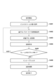
- 4 is a flowchart showing an encoding process according to the embodiment.
- 11 is a flowchart showing an image decoding process according to an embodiment.
- FIG. 2 is a hardware configuration diagram of a computer applicable to the image encoding device and decoding device according to the embodiment.
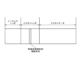
- FIG. 1 is a diagram showing an example of a bitstream structure.
- FIG. 13 is a diagram showing another example of a bit stream structure.
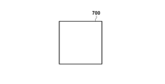
- FIG. 4 is a diagram showing an example of subblock division in which each subblock has the same size as a basic block, which is used in the present embodiment
- FIG. FIG. 2 is a diagram showing an example of division into four square sub-blocks used in the present embodiment.
- FIG. 13 is a diagram showing an example of simple copy pixel interpolation.
- FIG. 13 is a diagram showing an example of off-screen pixel interpolation using motion compensation pixel interpolation.
- FIG. 13 is a diagram showing an example of off-screen pixel interpolation using motion compensation pixel interpolation involving resolution conversion of a reference picture.
- FIG. 13 is a diagram showing an example of off-screen pixel interpolation using motion compensation pixel interpolation involving resolution conversion of a reference picture.
- 5A to 5C are diagrams showing an example of high-speed processing of motion compensation pixel interpolation in the present embodiment.
- 5A to 5C are diagrams showing an example of high-speed processing of motion compensation pixel interpolation in the present embodiment.
- Fig. 1 is a block diagram showing an image encoding device according to an embodiment.
- a control unit 100 is composed of a CPU and a memory that stores a program executed by the CPU, and controls the entire device.
- a terminal 101 is an input terminal for inputting image data.
- a source of moving image data to be encoded is connected to the terminal 101.
- the block division unit 102 divides one frame of an image received via the terminal 101 into multiple basic blocks, and outputs the block images in basic block units to the subsequent stage.
- the generating unit 103 generates offset information and the like used for resolution conversion of the reference picture, and outputs it to the resolution converting unit 113 and the integrated encoding unit 111.
- the offset information is information for setting a scaling window in each picture, and is information generated to calculate the enlargement ratio or reduction ratio of the picture (hereinafter referred to as resolution conversion control information).
- resolution conversion control information There are no particular limitations on the method for generating the resolution conversion control information, but the user may input the resolution conversion control information, information derived from operations such as zooming in and out detected in the image capturing device may be input as the resolution conversion control information, or resolution conversion control information specified in advance as an initial value may be used.
- the prediction unit 104 generates sub-blocks by dividing basic blocks. The prediction unit 104 then determines whether to perform intra-prediction, which is intra-frame prediction, or inter-prediction, which is inter-frame prediction, on a sub-block basis.
- the prediction unit 104 generates predicted image data by appropriately referring to an image in which pixels outside the screen boundary are interpolated (hereinafter referred to as an interpolated image) supplied from the interpolation unit 114.
- the prediction unit 104 calculates a prediction error from the image data to be coded and the generated predicted image data, and outputs the prediction error to the transformation and quantization unit 105.
- the prediction unit 104 also outputs information necessary for prediction, such as sub-block division, prediction mode, motion vector, etc., together with the prediction error. Hereinafter, this information necessary for prediction will be referred to as prediction information.
- the prediction unit 104 also outputs the prediction information to the interpolation unit 114.
- the transform/quantization unit 105 performs an orthogonal transform on the prediction error data in units of subblocks, and quantizes the obtained transform coefficients using a set quantization parameter to obtain residual coefficients.
- the quantization parameter is a parameter used to quantize the transform coefficients obtained by the orthogonal transform.
- the inverse quantization and inverse transform unit 106 inverse quantizes the residual coefficients output from the transform and quantization unit 105 to reproduce the transform coefficients, and then performs an inverse orthogonal transform to reproduce the prediction error data.
- Frame memory 108 is a memory that stores the reproduced image data.
- the resolution conversion unit 113 enlarges or reduces the image stored in the frame memory 108 based on the resolution conversion control information, and outputs the enlarged or reduced image as a resolution-converted image.
- the interpolation unit 114 generates interpolated image data by appropriately referring to the resolution-converted image output by the resolution conversion unit 113, the prediction information output by the prediction unit 104, and the filter image stored in the frame memory 108. The interpolation unit 114 then outputs the generated interpolated image data to the prediction unit 104 and the image reproduction unit 107.
- the interpolation unit 114 may store the generated image data including information on the off-screen pixels in the frame memory 108 as an interpolated image.
- the interpolation unit 114 may also retrieve the generated interpolated image from the frame memory 108 and output it to the prediction unit 104 and the image reproduction unit 107.
- the image reproduction unit 107 generates reproduced image data from the interpolated image data output by the interpolation unit 114 and the prediction error data based on the prediction information output by the prediction unit 104.
- the in-loop filter unit 109 performs in-loop filter processing such as deblocking filtering and sample adaptive offset on the reconstructed image.
- the encoding unit 110 encodes the residual coefficients output from the transform/quantization unit 105 and the prediction information output from the prediction unit 104 to generate coded data.
- the integrated coding unit 111 encodes the resolution conversion control information output by the generation unit 103 to generate header code data. The integrated coding unit 111 then combines this with the code data output by the coding unit 110 to form a bit stream.
- Terminal 112 is an output terminal that outputs the bit stream generated by the integrated encoding unit 111 to the outside.
- the output destination can be a network or a storage device (including a recording medium).
- moving image data is input in frame units, but it may also be configured to input one frame of still image data.
- the generating unit 103 Prior to encoding an image, the generating unit 103 generates resolution conversion control information.
- the resolution conversion control information includes the horizontal and vertical sizes of the current picture, offset information representing the scaling window of the current picture, and horizontal and vertical resolution conversion magnifications.
- the horizontal and vertical sizes of the current picture are the number of pixels in the horizontal direction and the number of pixels in the vertical direction of the image input from the terminal 101.
- the offset information representing the scaling window is information that specifies the position and size of the scaling window for the current picture.
- the position and size of the scaling window are specified using the distance from each of the left, right, top, and bottom sides of the current picture to each side of the scaling window, and this is used as the offset information.
- the offset for each side is expressed in number of pixels.
- the offset is expressed as a positive value from the screen boundary of the picture toward the center, and a value from the screen boundary toward the outside is expressed as a negative value.
- the offset for each side is expressed as the left side offset, right side offset, top side offset, and bottom side offset.
- the offset of the current picture is distinguished as offset C
- the offset of the reference picture is distinguished as offset R.
- the generation unit 103 uses the offsets for each side described above to calculate the resolution conversion factor, which represents the enlargement or reduction ratio of the reference picture relative to the current picture, for both the horizontal and vertical directions.
- the horizontal resolution conversion magnification is calculated by the following formula.
- Horizontal resolution conversion ratio (horizontal size of reference picture ⁇ left side offset R ⁇ right side offset R)/(horizontal size of current picture ⁇ left side offset C ⁇ right side offset C)
- the resolution conversion magnification for the current picture is calculated for all reference pictures that can be referred to in encoding the current picture.
- the generation unit 103 stores the resolution conversion magnification calculated in this manner in the resolution conversion control information, and outputs the resolution conversion control information to the resolution conversion unit 113 and the integrated encoding unit 111.
- One frame of image data input from terminal 101 is supplied to block division unit 102.
- the block division unit 102 divides the input image data into multiple basic blocks and outputs the basic block images to the prediction unit 104.
- the prediction unit 104 performs prediction processing on the image data (basic block image) input from the block division unit 102. Specifically, the prediction unit 104 first performs a process of dividing the input basic block size image into smaller sub-blocks (sub-block division process).
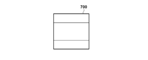
- Figures 7A to 7F show examples of dividing a basic block into sub-blocks.
- Reference number 700 in a bold frame represents a basic block, and for ease of explanation, the size of a basic block is assumed to be 32x32 pixels, and each rectangle in the bold frame represents a sub-block.
- Figure 7A shows an example in which one sub-block is the same size as a basic block.
- FIG. 7B shows an example of division into four square sub-blocks.
- each of the four sub-blocks in FIG. 7B is 16 ⁇ 16 pixels in size.
- FIGS. 7C to 7F show examples of the types of rectangular sub-blocks obtained by sub-division.
- FIG. 7C shows an example of division of a basic block into two vertically long rectangular sub-blocks of 16 ⁇ 32 pixels in size.
- FIG. 7D shows a basic block divided into two horizontally long rectangular sub-blocks of 32 ⁇ 16 pixels.
- FIGS. 7E and 7F show a rectangular sub-block division at a ratio of 1:2:1. In this way, in this embodiment, encoding processing is performed using not only square but also rectangular sub-blocks.
- the prediction unit 104 determines a prediction mode for each subblock to be processed. Specifically, the prediction unit 104 determines whether to use intra prediction, which uses encoded pixels of the current picture including the subblock to be processed, or inter prediction, which uses pixels of an encoded picture other than the current picture. The prediction unit 104 then generates predicted image data from the determined prediction mode and encoded pixels. Furthermore, the prediction unit 104 generates prediction error data from the input image data and the generated predicted image data, and outputs the generated prediction error data to the conversion/quantization unit 105. Note that the interpolation unit 114 may generate pixels outside the screen boundary of the reference picture by pixel interpolation, or the interpolation unit 114 may generate pixels outside the screen boundary of the reference picture by converting the resolution of encoded pixels.
- the prediction unit 104 also outputs information such as subblock division and prediction mode as prediction information to the encoding unit 110 and the image reproduction unit 107.
- the transform/quantization unit 105 performs frequency transform on the prediction error data of the subblock predicted by the prediction unit 104, and then performs quantization.
- the quantization parameter may be input by the user, may be calculated from the characteristics of the input image, or may be specified in advance as an initial value.
- the inverse quantization and inverse transform unit 106 inverse quantizes the input residual coefficients to regenerate the transform coefficients, and then performs inverse orthogonal transform on the regenerated transform coefficients to regenerate the prediction error data.
- the inverse quantization and inverse transform unit 106 then outputs the regenerated prediction error data to the image reproduction unit 107. Note that the quantization parameter used by the inverse quantization and inverse transform unit 106 when performing inverse quantization processing on a sub-block is the same as the quantization parameter used by the transform and quantization unit 105 when quantizing that sub-block.
- the image reproduction unit 107 generates a predicted image based on the prediction information input from the prediction unit 104, appropriately referring to the interpolated image supplied from the interpolation unit 114.
- the image reproduction unit 107 then reproduces image data from the generated predicted image and the prediction error data generated by the inverse quantization and inverse transform unit 106, and stores the reproduced image data in the frame memory 108.
- the in-loop filter unit 109 reads the reconstructed image from the frame memory 108 and performs in-loop filter processing such as a deblocking filter.
- the in-loop filter processing is performed based on the prediction mode of the prediction unit 104, the value of the quantization parameter used by the transformation and quantization unit 105, the presence or absence of non-zero values in the processing sub-block after quantization, or sub-block division information.
- the in-loop filter unit 109 stores the image data obtained by the filter processing back in the frame memory 108.
- the resolution conversion unit 113 enlarges or reduces the image stored in the frame memory 108 based on the resolution conversion control information. The resolution conversion unit 113 then outputs the image after enlargement or reduction as a resolution-converted image.
- the horizontal and vertical resolution conversion magnifications are calculated as follows using the above-mentioned formula for calculating the resolution conversion magnification.
- the resolution conversion magnification indicates the size of the rectangular area of the reference picture to which the offset is applied, with respect to the rectangular area of the current picture to which the offset is applied.
- the reference picture is in a state of being reduced by 0.75, that is, 3/4 times, with respect to the current picture. Therefore, in this case, the resolution conversion unit 113 generates a resolution-converted image by enlarging the reference picture by a magnification of 4/3 times, which is the inverse number of the resolution conversion magnification.
- the resolution conversion unit 113 outputs the generated resolution-converted image to the interpolation unit 114.
- the interpolation filter or thinning filter (hereinafter referred to as the resolution conversion filter) used for the resolution conversion is not particularly limited, but the user may input one or more resolution conversion filters, or a filter designated in advance as an initial value may be used.
- the resolution conversion unit 113 may switch between multiple resolution conversion filters according to the resolution conversion magnification to generate a resolution-converted image. In this way, by enlarging or reducing the reference picture based on the resolution conversion magnification, inter prediction following the enlargement or reduction of an object in a video in a zoom-in or zoom-out scene is possible.
- no offset is set in the current picture, but the present embodiment is not limited to this, and a scaling window may be set in the current picture.
- the horizontal size of the current picture and the reference picture is 1920 pixels, and the vertical size is 1080 pixels.
- the left and right offsets set in the reference picture are 510 pixels, and the top and bottom offsets are 270 pixels.
- the left and right offsets set in the current picture are 360 pixels, and the top and bottom offsets are 180 pixels.
- the horizontal and vertical sizes of the current picture and the reference picture may have different numbers of pixels. For example, assume that the horizontal size of the current picture is 1920 pixels and the vertical size is 1080 pixels, the horizontal size of the reference picture is 960 pixels and the vertical size is 540 pixels, and no scaling window is set for the current picture and the reference picture.
- the interpolation unit 114 appropriately references the resolution-converted image output by the resolution conversion unit 113, the prediction information output by the prediction unit 104, and the filter image stored in the frame memory 108, and generates image data by interpolating pixels outside the screen boundary of the current picture.
- the interpolation unit 114 uses the prediction information output by the prediction unit 104 to identify the positions of pixels required for interpolating the off-screen pixels, and generates off-screen pixels.
- the interpolation unit 114 then outputs the generated image data to the prediction unit 104 and the image reproduction unit 107.
- the information on the off-screen pixels may be generated each time a filter image is referenced, or the information on the off-screen pixels calculated once may be stored in the frame memory 108 as an interpolated image associated with the filter image.
- the interpolation unit 114 In order to generate image data, the interpolation unit 114 first retrieves from the frame memory 108 a filter image of the current picture to be subjected to the interpolation of off-screen pixels, and stores the image together with the prediction information used in the coding of the current picture input from the prediction unit 104. Next, the interpolation unit 114 reads out the prediction modes for all sub-blocks that are adjacent to the inside of the screen boundary of the filter image of the current picture from the prediction information.
- the interpolation unit 114 determines a pixel interpolation method for the outside of the screen boundary of the filter image of the current picture according to the state of the prediction mode of each block (hereinafter referred to as a border block) that is adjacent to the screen boundary of the current picture from the inside that has been read out.
- an interpolation method that generates pixels within the screen boundary of a reference picture by simply duplicating pixels within the screen boundary of the reference picture to the outside of the screen boundary of the same reference picture (hereinafter referred to as a simple copy pixel interpolation) is used, or a motion compensation pixel interpolation method that generates pixels within the screen boundary of a reference picture using pixels within the screen boundary of a reference picture different from the reference picture is used.
- a simple copy pixel interpolation an interpolation method that generates pixels within the screen boundary of a reference picture by simply duplicating pixels within the screen boundary of the reference picture to the outside of the screen boundary of the same reference picture
- a motion compensation pixel interpolation method that generates pixels within the screen boundary of a reference picture using pixels within the screen boundary of a reference picture different from the reference picture is used.
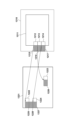
- the 10A and 10B show a case where the prediction unit 104 encodes a sub-block 1002 by inter prediction.
- the current picture 1001 shown in a thick frame on the right is the subject of encoding, and the rectangular area shown in a thick frame on the center is a reference picture 1011.
- the thin frame 1010 is an area having pixels outside the screen boundary of the reference picture 1011, and the pixels outside the screen boundary are generated by simple duplicated pixel interpolation or motion compensated pixel interpolation.
- the predicted image 1012 shown in the rectangular area of the reference picture 1011 represents the predicted block of the sub-block 1002 generated by the prediction unit 104 by inter prediction.
- the left side of the border block 1013 and the left side of the border block 1014 are in contact with the left side of the reference picture 1011 from the inside, and the prediction mode of the border block 1013 and the border block 1014 is inter prediction.
- the rectangular area 1015 and the rectangular area 1016 are filled with pixels generated by simple copy pixel interpolation or motion compensation pixel interpolation.
- the interpolation unit 114 generates pixels outside the screen boundary of the reference picture 1011 by using simple copy pixel interpolation or motion compensation pixel interpolation in the cases where the top side of the border block contacts the top side of the reference picture from the inside, where the right side of the border block contacts the right side of the reference picture from the inside, and where the bottom side of the border block contacts the bottom side of the reference picture from the inside, similarly to the case where the left side of the border block contacts the left side of the reference picture from the inside. Furthermore, when using motion compensation pixel interpolation, the interpolation unit 114 generates pixels outside the screen boundary of the reference picture that are not generated by using motion compensation pixel interpolation by simple copy pixel interpolation using pixels on the screen boundary of the reference picture.
- pixels located outside the screen boundary of the reference picture are generated by using motion compensation pixel interpolation for each of all border blocks that contact the inside of the screen boundary of the reference picture, based on the motion information of each border block. Furthermore, when processing each border block, pixels located outside the screen boundary of the reference picture are generated without referring to the motion information of other border blocks.
- the interpolation image 1021 is a filter image used for inter-prediction of the border block of the reference picture 1011, and is a picture taken from the frame memory 108. Furthermore, the pixel values within the screen boundary of this picture are used to generate pixels outside the screen boundary of the reference picture by motion compensation pixel interpolation. No scaling window is set for the interpolation image 1021 and the reference picture 1011, and all offsets are 0. Therefore, the resolution conversion factor is 1 in both the horizontal and vertical directions, and there is no need to convert the resolution of the interpolation image 1021 in the inter-prediction of the border block 1013.
- the interpolation unit 114 uses a group of pixels in a rectangular area 1025 of the interpolation image 1021 to generate pixels in a rectangular area 1015 located outside the screen boundary of the reference picture. Similarly, the interpolation unit 114 uses a group of pixels in a rectangular area 1026 of the interpolation image 1021 to generate pixels in a rectangular area 1016 located outside the screen boundary of the reference picture.
- the interpolation unit 114 generates pixels outside the screen boundary of the reference picture constituting the predicted image 1012 of the reference picture 1011 referred to by inter prediction of the sub-block 1002 by motion compensation pixel interpolation using pixels within the screen boundary of the interpolation image 1021. Furthermore, the interpolation unit 114 stores the reference picture in which the outside of the screen boundary of the reference picture generated by performing motion compensation pixel interpolation has been interpolated as an interpolated image in the frame memory 108 for all the boundary blocks of the reference picture 1011.
- either the offset of the scaling window set for the interpolation image 1021 or the reference picture 1011 is other than 0. That is, in the inter prediction of the boundary block 1013, the resolution of the interpolation image 1021 needs to be converted. Therefore, the prediction block 1023 corresponding to the boundary block 1013 located inside the prediction image 1012 is located inside the screen boundary of not the interpolation image 1021 but a resolution-converted image (hereinafter referred to as a resolution-converted interpolation image) whose resolution has been converted based on the offset information of the interpolation image 1021 and the reference picture 1011. Similarly, the prediction block 1024 corresponding to the boundary block 1014 located inside the prediction image 1012 is located inside the screen boundary of the resolution-converted interpolation image 1022 but not the interpolation image 1021.
- a scaling window may be set in the current picture 1001 and the reference picture 1011.
- the horizontal size of the reference picture 1011 and the interpolation image 1021 is 1920 pixels
- the vertical size is 1080 pixels
- the left side offset and right side offset set in the interpolation image 1021 are 240 pixels
- the top side offset and bottom side offset are 135 pixels.
- the offsets of the four sides of the reference picture are each 0 pixels.
- the resolution conversion magnification is 0.75 in the horizontal and vertical directions using the above-mentioned calculation formula. Therefore, the resolution-converted interpolation image 1022 is an image obtained by enlarging the interpolation image 1021 by 4/3 times, which is the inverse of 0.75. In this way, the resolution-converted interpolation image 1022 is generated from the interpolation image 1021 based on the reference picture 1011 and the offset information set in the interpolation image 1021.
- predicted image 1012 of reference picture 1011 represents a predicted block of sub-block 1002 generated by prediction unit 104 through inter prediction. Furthermore, the prediction mode of boundary blocks 1013 and 1014 of reference picture 1011 included in predicted image 1012 is inter prediction, and motion vectors are generated for prediction blocks 1023 and 1024 within the screen boundary of resolution-converted interpolation image 1022. Furthermore, the left sides of boundary blocks 1013 and 1014 are in contact with the left side of reference picture 1011 from the inside.
- an offset is set in either interpolation image 1021 originally referred to by the boundary block of reference picture 1011 or reference picture 1011, so the predicted image used for inter prediction of boundary blocks 1013 and 1014 is not interpolation image 1021, but resolution-converted interpolation image 1022 obtained by converting the resolution of interpolation image 1021 as described above. Therefore, the prediction block 1023 corresponding to the boundary block 1013 is located inside the screen boundary of the resolution-converted interpolation image 1022. Similarly, the prediction block 1024 corresponding to the boundary block 1014 is also located inside the screen boundary of the resolution-converted interpolation image 1022.
- a part of the pixel group of the prediction image 1012 is pixels of a rectangular area 1015 and a rectangular area 1016 composed of pixels outside the screen boundary of the reference picture 1011.
- the pixels of the rectangular area 1015 and the rectangular area 1016 are generated using the above-mentioned simple copy pixel interpolation or motion compensation pixel interpolation.
- the pixel group of the rectangular area 1015 located to the left of the boundary block 1013 is generated using a rectangular area 1025 located inside the screen boundary of the resolution-converted interpolation image 1022 referred to by the boundary block 1013.
- the interpolation unit 114 generates pixels outside the screen boundary of the reference picture constituting the predicted image 1012 of the reference picture 1011 referenced by inter prediction of the sub-block 1002 by motion compensation pixel interpolation using pixels within the screen boundary of the resolution-converted interpolation image 1022.
- the interpolation unit 114 stores, as an interpolated image, in the frame memory 108 the reference picture in which the outside of the screen boundary of the reference picture generated by performing motion compensation pixel interpolation has been interpolated for all boundary blocks of the reference picture 1011.
- the encoding unit 110 performs entropy encoding on a block-by-block basis on the residual coefficients generated by the transform/quantization unit 105 and the prediction information input from the prediction unit 104, to generate coded data.
- the method of entropy coding is not particularly limited, but typically, Golomb coding, arithmetic coding, Huffman coding, etc. can be used.
- the generated code data is output to the integrated coding unit 111.
- an identifier indicating the difference between the quantization parameter of the subblock to be coded and a predicted value calculated using the quantization parameter of the subblock coded before the subblock is coded.
- the quantization parameter coded immediately before the subblock in coding order is used as the predicted value to calculate the difference between the quantization parameter of the subblock, but the predicted value of the quantization parameter is not limited to this.
- the quantization parameter of the subblock adjacent to the left or above the subblock may be used as the predicted value, or a value calculated from the quantization parameters of multiple subblocks, such as the average value, may be used as the predicted value. Furthermore, if the subblock to be processed is the first subblock in coding order among the subblocks belonging to the first basic block in the basic block row, the quantization parameter of the subblock in the basic block immediately above may be used as the predicted value. This enables parallel processing on a basic block row basis. Note that the first basic block in a basic block row refers to a basic block that has a picture boundary or tile boundary on its left side.
- the integrated encoding unit 111 encodes the resolution conversion control information.
- the resolution conversion control information includes the number of horizontal and vertical pixels of the current picture, and offset information such as the left side offset, right side offset, top side offset, and bottom side offset. Each offset is the number of pixels, and has a sign indicating positive or negative.
- the integrated encoding unit 111 also encodes a flag indicating whether motion compensation pixel interpolation is to be performed. Specifically, if motion compensation pixel interpolation is to be performed, the flag is encoded as 1, and if motion compensation pixel interpolation is not to be performed, the flag is encoded as 0.
- the method of encoding the resolution conversion control information and the flag indicating the execution of motion compensation pixel interpolation is not particularly specified, but Golomb encoding, arithmetic encoding, Huffman encoding, etc. can be used.
- the integrated encoding unit 111 also multiplexes these codes and the code data input from the encoding unit 110 to form a bit stream. Finally, the bit stream is output to the outside from terminal 112.
- FIG. 6A shows an example of the data structure of a bitstream including the encoded resolution conversion control information.
- the resolution conversion control information is included in one of the headers of a sequence, a picture, etc. In this embodiment, it is included in the header part of the picture as shown in FIG. 6A. However, the location where the resolution conversion control information is stored is not limited to this, and it may be included in the header part of the sequence as shown in FIG. 6B.
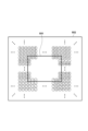
- simple copy pixel interpolation will be described with reference to FIG. 8.
- FIG. 8 shows an example of simple copy pixel interpolation generated by simply copying pixels within the screen boundary of a reference picture to outside the screen boundary of the same reference picture.
- the thick frame 801 represents the screen boundary of the reference picture
- the thin frame 802 represents the area outside the screen boundary of the reference picture.
- Each circle with an alphabet represents pixel A to pixel T within and outside the screen boundary.
- three consecutive black circles represent the omission of the notation of pixels outside the screen boundary.
- pixels that are in contact with the screen boundary of the reference picture and are located inside the screen boundary of the reference picture are simply copied in the normal direction of the picture boundary to generate pixels outside the screen boundary of the reference picture. For example, in the screen boundary at the left side of the reference picture, the pixel in the screen boundary that is located third from the top is pixel C.
- the pixel C is copied with the same value continuously along the normal line of the left side of the reference picture, that is, toward the left outside the screen boundary of the reference picture, to generate pixels outside the screen boundary of the reference picture.
- pixels inside the screen boundary are copied to the right, in the screen boundary at the top side of the reference picture, pixels inside the screen boundary are copied upward, and in the screen boundary at the bottom side of the reference picture, pixels inside the screen boundary are copied downward to generate pixels outside the screen boundary of the reference picture.
- pixels in the upper left, upper right, lower left, and lower right regions of the reference picture that are not located on the normal lines of the left, right, top, and bottom sides are generated using pixels located at the four corners within the screen boundary of the reference picture. Specifically, the pixels in the upper left region are simply copied from pixel A at the upper left within the screen boundary. Similarly, the pixels in the upper right region are simply copied from pixel K at the upper right within the screen boundary, the pixels in the lower left region are simply copied from pixel F at the lower left within the screen boundary, and the pixels in the lower right region are simply copied from pixel P at the lower right within the screen boundary.
- pixel values outside the screen boundary of each reference picture can be generated quickly.
- FIG. 9 shows an example of an interpolation in which pixels outside the screen boundary of a filter image of a current picture are generated using pixels within the screen boundary of a filter image retrieved from the frame memory 108.
- the retrieved filter image is a filter image that has been subjected to in-loop filter processing and that each subblock to be coded of the current picture refers to by inter prediction, or an interpolated image in which pixels outside the screen boundary have been generated by the interpolation unit 114.
- a thick frame 901 represents the screen boundary of the filter image of the current picture that is the reference source (hereinafter referred to as the current filter image), and an area 902 indicated by a thin frame represents an area outside the screen boundary of the current filter image.
- a border block 903 is an area that contacts the left side of the screen boundary of the current filter image from the inside.
- FIG. 9 shows a case of a square block of 4 ⁇ 4 pixels, but this embodiment is not limited to this.
- a square block of 8 ⁇ 8 pixels or a rectangular block of 8 ⁇ 16 pixels may be used.
- the size of the square block is represented by N ⁇ N pixels.
- the thick line showing the perimeter in the left diagram of FIG. 9 represents the screen boundary of the reference filter image 905 that the border block of the current filter image references by inter prediction, unlike the above-mentioned current filter image retrieved from the frame memory 108, and the square block 906 is an area located inside the reference filter image.
- the interpolation unit 114 identifies the position of the square block 906 that is the reference of the border block 903 based on the prediction information of the border block 903. Since the square block 906 is the block used to calculate the prediction error of the border block 903, the border block 903 and the square block 906 have the same block size.
- the rectangular area 907 indicated by the thick frame is an area whose left side is in contact with the left side of the square block 906 and the right side of the screen boundary of the reference filter image 905, and the distance between these two sides is M.
- the right side of rectangular region 907 and the left side of square block 906 are the same line segment, so the vertical size of rectangular region 907 is N pixels, the same as square block 906. Therefore, rectangular region 907 is a rectangular region of M x N pixels.
- each circle numbered 0 to 19 is a group of pixels that fills the rectangular area 907 indicated by the thick line.
- the group of pixels of the identified rectangular area 907 of the reference filter image is used to generate a rectangular area 904 of the same size as the rectangular area 907 in the current filter image.
- the pixels contained in the rectangular area 904 may be generated by simply duplicating the same values as the pixels of the rectangular area 907 of the reference filter image, or a sharpening filter or smoothing filter may be applied.
- pixels belonging to the area 902 outside the screen boundary of the current filter image are generated by motion compensation pixel interpolation, but not all pixels of the area 902 are necessarily generated. Pixels outside the screen boundary whose values are undetermined are generated using simple replication pixel interpolation. For example, when the left side of the square block 906 is located to the left of the left side of the reference filter image 905, the boundary block 903 refers to the outside of the screen boundary of the reference filter image 905, so that the rectangular area 907 specified within the screen boundary of the reference filter image does not have any pixels.
- pixels located outside the pixel group generated using motion compensation pixel interpolation are generated in the same way as when the left edge of the border block touches the left edge of the reference picture from the inside. This generates screen boundary pixels located to the left, right, above, and below the current filter image. Note that for pixels in the upper left, upper right, lower left, and lower right areas, pixels outside the screen boundary are generated using the simple duplicated pixel interpolation described above.
- the interpolation unit 114 uses the above-mentioned simple duplicated pixel interpolation or motion compensated pixel interpolation to interpolate pixels outside the screen boundary of the current picture, and outputs the processing result to the frame memory 108 as an interpolated image.
- FIG. 3 is a flowchart showing the encoding process in the image encoding device according to this embodiment.
- the generation unit 103 determines offset information for use in converting the resolution of a reference picture by the resolution conversion unit 113.
- the generation unit 103 uses the determined offset information as resolution conversion control information.
- the generation unit 103 outputs the information to the integrated coding unit 111.
- the block division unit 102 divides the input image in frames into basic block units.
- the prediction unit 104 performs a division process on the basic block unit image data generated in S301 to generate subblocks.
- the prediction unit 104 then performs a prediction process on the generated subblock unit to generate prediction information such as block division and prediction mode, and predicted image data.
- the prediction unit 104 then calculates prediction error data from the input image data and the generated predicted image data. Specifically, the prediction unit 104 sets the prediction mode of the subblock to inter prediction.
- the prediction unit 104 then generates a prediction block including pixels outside the screen boundary of the reference picture generated by the interpolation unit 114 using pixels within the screen boundary of the interpolation image. Furthermore, the prediction unit 104 generates prediction error data from information on the prediction block and the subblock.
- the generation unit 103 uses offset information of the current picture included in the resolution conversion control information and offset information of each reference picture to calculate a resolution conversion magnification for the current picture of each referenceable reference picture. Then, a resolution-converted interpolation image is generated by converting the interpolation image based on the above-mentioned resolution conversion magnification.
- the prediction unit 104 sets the prediction mode of the sub-block to inter prediction. The prediction unit 104 then generates a prediction block including pixels outside the screen boundary of the reference picture generated by the interpolation unit 114 using pixels within the screen boundary of the resolution-converted interpolation image. Furthermore, the prediction unit 104 generates prediction error data from information on the prediction block and the sub-block.
- the transform/quantization unit 105 performs an orthogonal transform on the prediction error data calculated in S303 to generate transform coefficients.
- the transform/quantization unit 105 then quantizes the transform coefficients using the quantization parameter to generate residual coefficients.
- the inverse quantization and inverse transform unit 106 inverse quantizes and inversely orthogonally transforms the residual coefficients generated in S304 to reproduce the prediction error.
- the inverse quantization process in this step uses the same quantization parameters as those used in S304.
- the image regeneration unit 107 regenerates a predicted image based on the prediction information generated in S303.
- the image regeneration unit 107 further regenerates image data from the regenerated predicted image and the prediction error generated in S305.
- the encoding unit 110 encodes the prediction information generated in S303 and the residual coefficients generated in S304 together with the block division information to generate coded data.
- the encoding unit 110 also generates a bitstream including other coded data such as quantization parameters.
- control unit 100 of the image encoding device determines whether or not the encoding of all basic blocks in the frame of interest (current picture) has been completed. If the control unit 100 determines that the encoding has been completed, the process proceeds to S309. If the control unit 100 determines that an unprocessed basic block exists, the process returns to S303 to encode the next basic block.
- the in-loop filter unit 109 performs in-loop filter processing on the image data reproduced in S306 to generate a filtered image (filter image).
- the resolution conversion unit 113 extracts from the frame memory 108 the filter image of the current picture and the reference picture that the boundary block of the current picture refers to in inter prediction.
- the resolution conversion unit 113 also uses the resolution conversion control information supplied from the generation unit 103 to enlarge or reduce the reference picture to generate a resolution-converted image.
- the interpolation unit 114 generates and interpolates a group of pixels located outside the screen boundary of the filter image of the current picture, adjacent to the boundary block of the filter image of the current picture, using simple duplicated pixel interpolation or motion compensated pixel interpolation. For each boundary block, when motion compensated pixel interpolation is used, pixels outside the screen boundary are generated using pixels located within the screen boundary of the resolution-converted image.
- the interpolation unit 114 then stores the interpolated image obtained by generating and interpolating the pixels outside the screen boundary in the frame memory 108, and ends the process.
- resolution conversion control information is generated in S301, and in S310, the reference picture is enlarged or reduced based on the resolution conversion control information, thereby improving the accuracy of generating a predicted image in motion compensation pixel interpolation, and furthermore, using such a predicted image can reduce prediction errors.
- the image quality of the encoded image can be improved while suppressing the amount of data in the entire bitstream generated.
- pixels outside the screen boundary of the reference picture that are not generated using motion compensation pixel interpolation are generated using pixels inside the screen boundary of the reference picture, but this is not limited to this.
- the pixel calculated by motion compensation pixel interpolation outside the screen boundary that is located at the farthest position from the screen boundary of the reference picture may be set as the terminal pixel, and this terminal pixel may be further duplicated, or the average value of the terminal pixel and the pixel inside the screen boundary used in the simple duplicated pixel interpolation may be further duplicated.
- the thick frame in the center of the right diagram in Figure 11 is the reference picture 1101, and the thin frame 1102 represents the area outside the screen boundary of the reference picture 1101.
- Area 1103 is a border block, and the left side of the border block contacts the left side of the reference picture 1101 from the inside.
- Area 1104 is generated by motion compensation pixel interpolation using pixels of a picture coded before the reference picture, and its right side contacts the left side of the reference picture 1101 from the outside.
- the inside of area 1104 is filled with 10 pixels numbered 0 to 9. Of these, pixels 0 and 5 are the terminal pixels. In this case, pixel Y located outside area 1104 may have the same value as pixel V or may have the same value as terminal pixel 0.
- the average value of pixel V and terminal pixel 0 may be used.
- pixel Y may be calculated using any one of the average value, median value, maximum value, and minimum value of the pixel group on the normal line of the left side of the boundary block in which pixel V exists, including pixel V included in region 1103.
- pixel Y may be calculated using any one of the average value, median value, maximum value, and minimum value of the pixel group included in region 1104, i.e., pixels 0 to 4.
- pixel Y may be calculated using any one of the average value, median value, maximum value, and minimum value of the pixel group on the normal line including regions 1103 and 1104.
- pixel Y may be calculated using any one of the average value, median value, maximum value, and minimum value of the value calculated using the pixel group in region 1104 and the value calculated using the pixel group in region 1103.
- pixel Z may be calculated using pixels on the normal line of the left side of the boundary block in which pixel W exists.
- the maximum value is used, and when the value of the pixel inside the screen boundary or the end pixel used in the simple copy pixel interpolation is significantly smaller than other values, the minimum value is used, thereby avoiding the influence of local noise.
- a pixel located outside the pixel group generated using the motion compensation pixel interpolation may be generated in the same manner as in the case where the left side of the border block contacts the left side of the reference picture from the inside.
- the pixels in the upper left, upper right, lower left, and lower right areas are generated using pixels located at the four corners within the screen boundary of the reference picture, but this is not limited to this. Calculation may also be performed using pixels located outside the four corner pixels of the reference picture.
- FIG. 11 Each rectangular area in FIG. 11 is the same as described above, so description will be omitted.
- the interpolation image 1111 is an image referenced by a border block 1105 located in the upper left corner of the reference picture 1101 by inter prediction
- the area 1115 is a prediction block corresponding to the border block 1105.
- pixels 10, 12, 20, and 24 are generated by motion compensation pixel interpolation for pixel A in the upper left corner of reference picture 1101.
- pixels 11, 21, 22, and 23 of reference picture 1101 may be generated from pixels 11, 21, 22, and 23 of interpolation image 1111. This allows the pixel located in the upper left corner of the reference picture to be generated more accurately than by simply duplicating pixel A.
- pixel 11 may be generated using the average value of pixels 10 and 12.
- pixel 11 may be generated using either the average value or the median value of pixels 10, 12, and pixel A.
- pixels 21 to 23 may be generated using the average value of pixels 20 and 24.
- pixels 21 to 23 may be generated using either the average value or the median value of pixels 20, 24, and pixel A. Using the average value allows for the generation of pixels that reflect the state of the signals to the left and above the reference picture, while using the median value allows for the generation of pixels that are not affected by outliers.
- pixels 50, 52, 60, and 64 are generated by motion compensation pixel interpolation.
- pixels 51, 61, 62, and 63 of reference picture 1101 may be generated from pixels 51, 61, 62, and 63 of interpolation image 1111. This allows the pixel located in the upper right corner of the reference picture to be generated with greater accuracy than by simply duplicating pixel K.
- pixel 51 may be generated using the average value of pixels 50 and 52.
- pixel 51 may be generated using either the average value or the median value of pixels 50, 52, and pixel K.
- pixels 61 to 63 may be generated using the average value of pixels 60 and 64.
- pixels 61 to 63 may be generated using either the average value or the median value of pixels 60, 64, and pixel K.
- Using the average value makes it possible to generate pixels that reflect the state of the signals above and to the right of the reference picture, while using the median value makes it possible to generate pixels that are not affected by outliers.
- pixels 30, 32, 40, and 44 are generated by motion compensation pixel interpolation.
- pixels 31, 41, 42, and 43 of reference picture 1101 may be generated from pixels 31, 41, 42, and 43 of interpolation image 1111. This allows the pixel located in the upper left corner of the reference picture to be generated more accurately than by simply duplicating pixel F.
- pixel 31 may be generated using the average value of pixels 30 and 32.
- pixel 31 may be generated using either the average value or the median value of pixels 30, 32, and pixel F.
- pixels 41 to 43 may be generated using the average value of pixels 40 and 44.
- pixels 41 to 43 may be generated using either the average value or the median value of pixels 40, 44, and pixel F.
- the average value makes it possible to generate pixels that reflect the state of the signals to the left and below the reference picture, while using the median value makes it possible to generate pixels that are not affected by outliers.
- pixels 70, 72, 80, and 84 are generated by motion compensation pixel interpolation.
- pixels 71, 81, 82, and 83 of reference picture 1101 may be generated from pixels 71, 81, 82, and 83 of interpolation image 1111. This allows the pixel located in the upper left corner of the reference picture to be generated more accurately than by simply duplicating pixel P.
- pixel 71 may be generated using the average value of pixels 70 and 72.
- pixel 71 may be generated using either the average value or the median value of pixels 70, 72, and pixel P.
- pixels 81 to 83 may be generated using the average value of pixels 80 and 84.
- pixels 81 to 83 may be generated using either the average value or the median value of pixels 80, 84, and pixel P. Using the average value makes it possible to generate pixels that reflect the state of the signals to the right and below the reference picture, while using the median value makes it possible to generate pixels that are not affected by outliers.
- pixels located outside the screen boundary of the reference picture are generated based on the motion information of each border block without referring to the motion information of other border blocks, but this embodiment is not limited to this.
- Motion compensation pixel interpolation may be performed by referring to the motion information of border blocks located above, below, or to the left and right of the border block to be processed.
- FIG. 12 The thick frame on the right side of FIG. 12 is the screen boundary of the reference picture 1211, and the thin frame 1210 represents the area outside the boundary of the reference picture 1211.
- the left sides of the border blocks 1212, 1213, and 1214 are in contact with the left side of the reference picture from the inside, and the areas 1215, 1216, and 1217 corresponding to each border block are generated using pixels located within the screen boundary of the resolution-converted interpolation image 1221 obtained by converting the resolution of a picture encoded before the reference picture by motion compensation pixel interpolation, and the right sides of each are in contact with the left side of the reference picture from the outside.
- Each border block located inside the reference picture 1211 is sequentially selected from the top left to the bottom right, based on the prediction information of each border block, to identify a rectangular area of the resolution-converted interpolation image 1221 used for inter prediction located within the screen boundary of the resolution-converted interpolation image 1221.
- the areas used for inter prediction corresponding to the border blocks 1212, 1213, and 1214 are represented by border blocks 1222, 1223, and 1224, and rectangular areas 1225, 1226, and 1227 adjacent to each block are used to generate areas 1215, 1216, and 1217, which are pixel groups outside the screen area of the reference picture.
- the motion vectors of the border block 1212 and the border block 1214 are the same.
- the area 1223 which is the area used for inter prediction indicated by the motion information of the border block 1213, is not adjacent to the border block 1222 and the border block 1224.
- the motion vectors of the boundary block 1212 and the boundary block 1214 are the same, and the relative positional relationship between the boundary block 1212 and the boundary block 1214 coincides with the relative positional relationship between the boundary block 1222 and the boundary block 1224.
- the motion vector generated by inter prediction reflects the global motion of the entire screen.
- the pixels of the area 1216 may be generated using the area 1228 sandwiched between the rectangular area 1225 and the rectangular area 1227, rather than the pixels of the area 1226.
- 1 may be coded as a flag indicating the execution of the correction process of the left side of the reference picture
- 0 may be coded as a flag indicating that the correction process is not performed.
- a pixel located outside the pixel group generated using the motion compensation pixel interpolation may be generated in the same manner as when the left side of the border block contacts the left side of the reference picture from the inside.
- a flag indicating the execution of the correction process of the right side of the reference picture may be coded as 1, and when the correction process is not executed, a flag indicating the correction process is not executed may be coded as 0.
- a flag indicating the execution of the correction process of the top side of the reference picture may be coded as 1, and when the correction process is not executed, a flag indicating the correction process is not executed may be coded as 0.
- a flag indicating the execution of the correction process of the bottom side of the reference picture may be coded as 1, and when the correction process is not executed, a flag indicating the correction process is not executed may be coded as 0.
- pixels located outside the screen boundary of the reference picture are generated using motion compensated pixel interpolation for each of all border blocks that contact the inside of the screen boundary of the reference picture, but this embodiment is not limited to this.
- pixels outside the screen boundary may be generated collectively for rectangular areas sandwiched between rectangular areas adjacent to the border blocks at the four corners.
- the thick frame in Figures 13A and 13B indicates the screen boundary of reference picture 1311
- the thin frame 1310 indicates the area outside the boundary of reference picture 1311.
- the left sides of border blocks 1312 and 1313 contact the left side of the reference picture from the inside.
- Areas 1314 and 1315 corresponding to each border block are generated using pixels located within the screen boundary of resolution-converted interpolation image 1321 obtained by performing motion compensation pixel interpolation to convert the resolution of a picture coded before the reference picture.
- the right sides of areas 1314 and 1315 contact the left side of the reference picture from the outside.
- motion compensation pixel interpolation is performed on the border blocks located in the upper left corner, upper right corner, lower left corner, and lower right corner.
- a rectangular area of the resolution-converted interpolation image 1321 used for inter prediction located within the screen boundary of the resolution-converted interpolation image 1321 is identified based on the prediction information of each border block, from the upper left to the lower right.
- the areas used for inter prediction corresponding to the border blocks 1312 and 1313 are represented by prediction blocks 1322 and 1323, and rectangular areas 1324 and 1325 adjacent to each prediction block are used to generate areas 1314 and 1315, which are pixel groups outside the screen area of the reference picture. Furthermore, it is assumed that the motion vectors of the border block 1312 and the area 1314 are the same.
- the motion vectors of the boundary blocks 1312 and 1313 are the same, and the relative positional relationship between the regions 1314 and 1315 is the same as the relative positional relationship between the regions 1324 and 1325.
- the motion vector generated by inter prediction is considered to reflect the global motion of the entire screen. Therefore, in such a case, the region of the region 1316 may be generated using the region 1326 sandwiched between the regions 1324 and 1325.
- a flag indicating the execution of the collective interpolation process may be coded as 1, and when the collective interpolation process is not performed, a flag indicating that the collective interpolation process is not performed may be coded as 0.
- the motion vectors of the boundary blocks 1312 and 1313 are the same, and the relative positional relationship between the regions 1314 and 1315 is the same as the relative positional relationship between the regions 1324 and 1325.
- the motion vector generated by inter prediction is considered to reflect the global movement of the entire screen. Therefore, in such a case, the region of the region 1316 may be generated using the region 1326 sandwiched between the regions 1324 and 1325.
- FIG. 13B the motion vectors of the boundary blocks 1312 and 1313 are the same, and the relative positional relationship between the regions 1314 and 1315 is the same as the relative positional relationship between the regions 1324 and 1325.
- the pixels in the region 1316 other than the duplicated pixels may be interpolated using the simple repetitive pixel interpolation described above.
- a flag indicating that collective interpolation process is to be performed may be coded as 1, and when collective interpolation process is not to be performed, a flag indicating that collective interpolation process is not to be performed may be coded as 0.
- a pixel located outside the pixel group generated using motion compensation pixel interpolation may be generated in the same manner as in the case where the left side of the border block contacts the left side of the reference picture from the inside.
- a flag indicating that the correction process is to be performed on the right side of the reference picture may be coded as 1
- a flag indicating that the correction process is not to be performed may be coded as 0 if the correction process is not to be performed.
- a flag indicating that the correction process is to be performed on the top side of the reference picture may be coded as 1, and a flag indicating that the correction process is not to be performed may be coded as 0 if the correction process is not to be performed.
- a flag indicating that the correction process is to be performed on the bottom side of the reference picture may be coded as 1, and a flag indicating that the correction process is not to be performed may be coded as 0 if the correction process is not to be performed.
- image data is input frame by frame, and an encoding process is performed to generate and output a bitstream
- the target of the encoding process is not limited to image data.
- feature data used in machine learning such as object recognition may be input in a two-dimensional shape, and an encoding process is performed to encode the bitstream. This makes it possible to efficiently encode feature data used in machine learning.
- FIG. 2 is a block diagram showing the configuration of an image decoding device in the second embodiment.
- the control unit 200 is made up of a CPU and a memory that stores the programs executed by the CPU, and is responsible for controlling the entire device.
- Terminal 201 is an input terminal for inputting an encoded bitstream.
- the separation decoding unit 202 separates the bitstream input via terminal 201 into information related to the decoding process and encoded data related to residual coefficients.
- the separation decoding unit 202 also decodes encoded data present in the header portion of the bitstream.
- the separation decoding unit 202 decodes resolution conversion control information and outputs it to the subsequent stage. It is easy to understand the separation decoding unit 202 if you think of it as performing the reverse operation of the integrated encoding unit 111 in FIG. 1.
- the decoding unit 203 obtains residual coefficients and prediction information by decoding the encoded data output from the separation decoding unit 202.
- the inverse quantization and inverse transform unit 204 performs inverse quantization on the residual coefficients input in units of blocks, and then performs inverse orthogonal transform to obtain the prediction error.
- Frame memory 206 is a memory that stores image data of played pictures.
- the image reproduction unit 205 generates predicted image data using the prediction information input from the decoding unit 203 and the interpolated image data input from the interpolation unit 210. The image reproduction unit 205 then generates and outputs reproduced image data from this predicted image data and the prediction error data reproduced by the inverse quantization and inverse transform unit 204.
- the in-loop filter unit 207 performs in-loop filter processing such as a deblocking filter on the reconstructed image and outputs the filtered image.
- the resolution conversion unit 209 enlarges or reduces the filter image stored in the frame memory 206 based on the resolution conversion control information, generates a resolution-converted image, and outputs it as the resolution-converted image.
- the interpolation unit 210 generates interpolated image data by appropriately referring to the resolution-converted image output by the resolution conversion unit 209, the prediction information output by the decoding unit 203, and the filter image stored in the frame memory 206. The interpolation unit 210 then outputs the generated interpolated image data to the image reproduction unit 205. Note that the interpolation unit 210 may store the generated image data including information on the off-screen pixels in the frame memory 206 as an interpolated image. The interpolation unit 210 may also retrieve the generated interpolated image from the frame memory 206 and output it to the image reproduction unit 205.
- the image data of the current frame stored in the frame memory 206 is output to the outside via the terminal 208.
- the image decoding operation in the image decoding device is described below.
- the image decoding device of this embodiment decodes the bit stream generated by the image encoding device of the first embodiment.
- a control unit 200 is a processor that controls the entire image decoding device, and a bit stream input from a terminal 201 is input to a separation decoding unit 202.
- the separation decoding unit 202 separates the bit stream into information related to the decoding process and coded data related to coefficients, and decodes the coded data present in the header of the bit stream. Specifically, the separation decoding unit 202 first decodes resolution conversion control information from the picture header of the bit stream shown in FIG. 6A. Then, the separation decoding unit 202 outputs the resolution conversion control information obtained by decoding to the resolution conversion unit 209. Furthermore, the separation decoding unit 202 outputs coded data of the picture data in units of blocks to the decoding unit 203. Note that the decoded resolution conversion control information includes offset information representing the horizontal and vertical sizes of the current picture and the scaling window of the current picture.
- the offset information is an offset corresponding to the distance from each of the left, right, top, and bottom sides of the current picture.
- the offset for each side is expressed by the number of pixels.
- the offset is expressed as a positive value from the screen boundary of the picture toward the center, and a negative value from the screen boundary toward the outside.
- a resolution conversion magnification representing the enlargement ratio or reduction ratio of the reference picture with respect to the current picture is calculated for each of the horizontal and vertical directions.
- the horizontal and vertical resolution conversion magnifications are obtained according to the following formulas.
- Horizontal resolution conversion ratio (horizontal size of reference picture ⁇ left side offset R ⁇ right side offset R)/(horizontal size of current picture ⁇ left side offset C ⁇ right side offset C)
- Vertical resolution conversion ratio (vertical size of reference picture ⁇ top offset R ⁇ bottom offset R)/(vertical size of current picture ⁇ top offset C ⁇ bottom offset C)
- the decoding unit 203 decodes the encoded data to obtain residual coefficients, prediction information, and quantization parameters.
- the decoding unit 203 then outputs the residual coefficients and quantization parameters to the inverse quantization and inverse transform unit 204, and outputs the obtained prediction information to the image reproduction unit 205.
- the inverse quantization and inverse transform unit 204 performs inverse quantization on the input residual coefficients to generate orthogonal transform coefficients. Furthermore, the inverse quantization and inverse transform unit 204 performs inverse orthogonal transform on the generated orthogonal transform coefficients to regenerate prediction errors. Note that the quantization parameters used in the inverse quantization of each subblock by the inverse quantization and inverse transform unit 204 are the same as the quantization parameters used on the encoding side. The inverse quantization and inverse transform unit 204 outputs the acquired prediction information to the image reproduction unit 205.
- the image reproduction unit 205 generates a predicted image based on the interpolated image input from the interpolation unit 210, in which pixels outside the screen boundary have already been generated, and the prediction information input from the decoding unit 203.
- the image reproduction unit 205 then reproduces image data from this predicted image and the prediction error input from the inverse quantization and inverse transform unit 204, and stores the reproduced image data in the frame memory 206.
- the image data stored in the frame memory 206 is used as a reference when predicting the subsequent subblocks to be decoded when decoding.
- FIG. 10A and 10B show a case where the decoding unit 203 decodes a sub-block 1002 by inter prediction.
- the current picture 1001 shown in a thick frame on the right is the decoding target, and the reference picture 1011 shown in a thick frame in the center is a picture referenced by the sub-block of the current picture.
- the thin frame 1010 is an area having pixels outside the screen boundary of the reference picture 1011, and the pixels outside the screen boundary are generated by simple duplicated pixel interpolation or motion compensated pixel interpolation.
- the predicted image 1012 of the reference picture 1011 represents the predicted block of the sub-block 1002 identified by the image reproduction unit 205 based on the prediction information.
- the left side of the boundary block 1013 and the left side of the boundary block 1014 are in contact with the left side of the reference picture 1011 from the inside.
- the prediction mode of the boundary block 1013 and the boundary block 1014 is assumed to be inter prediction.
- the rectangular area 1015 and the rectangular area 1016 are filled with pixels generated by simple copy pixel interpolation or motion compensation pixel interpolation.
- the interpolation unit 210 generates pixels outside the screen boundary of the reference picture 1011 using simple copy pixel interpolation or motion compensation pixel interpolation, similar to the case where the left side of the boundary block is in contact with the left side of the reference picture from the inside.
- the interpolation unit 210 when using motion compensation pixel interpolation, the interpolation unit 210 generates pixels outside the screen boundary of the reference picture that are not generated using motion compensation pixel interpolation by simple copy pixel interpolation using pixels on the screen boundary of the reference picture. Then, in the motion compensation pixel interpolation of each border block, the interpolation unit 210 generates pixels located outside the screen boundary of the reference picture using motion compensation pixel interpolation for each of all border blocks that contact the inside of the screen boundary of the reference picture based on the motion information of each border block. Furthermore, in processing each border block, the interpolation unit 210 generates pixels located outside the screen boundary of the reference picture without referring to the motion information of other border blocks.
- the interpolation image 1021 is a filter image used for inter-prediction of the border block of the reference picture 1011, and is a picture taken out of the frame memory 206. Furthermore, the pixel values within the screen boundary of the interpolation image 1021 are used to generate pixels outside the screen boundary of the reference picture 1011 by motion compensation pixel interpolation. No scaling window is set for the interpolation image 1021 and the reference picture 1011, and all offsets are 0. Therefore, the resolution conversion factor is 1 in both the horizontal and vertical directions, and there is no need to convert the resolution of the interpolation image 1021 in the inter-prediction of the border block 1013.
- the interpolation unit 210 uses a group of pixels in a rectangular area 1025 of the interpolation image 1021 to generate pixels in a rectangular area 1015 located outside the screen boundary of the reference picture.
- the interpolation unit 210 uses a group of pixels in a rectangular area 1026 of the interpolation image 1021 to generate pixels in a rectangular area 1016 located outside the screen boundary of the reference picture.
- the interpolation unit 210 generates pixels outside the screen boundary of the reference picture constituting the predicted image 1012 of the reference picture 1011 referred to by inter prediction of the sub-block 1002 by motion compensation pixel interpolation using pixels within the screen boundary of the interpolation image 1021. Furthermore, the interpolation unit 210 stores the reference picture in which the outside of the screen boundary of the reference picture generated by performing motion compensation pixel interpolation has been interpolated as an interpolated image in the frame memory 206 for all the boundary blocks of the reference picture 1011.
- either the offset of the scaling window set for the interpolation image 1021 or the reference picture 1011 is other than 0. That is, in the inter prediction of the boundary block 1013, the resolution of the interpolation image 1021 needs to be converted. Therefore, the prediction block 1023 corresponding to the boundary block 1013 located inside the prediction image 1012 is located inside the screen boundary of not the interpolation image 1021 but the resolution-converted interpolation image whose resolution has been converted based on the offset information of the interpolation image 1021 and the reference picture 1011. Similarly, the prediction block 1024 corresponding to the boundary block 1014 located inside the prediction image 1012 is located inside the screen boundary of the resolution-converted interpolation image 1022 but not the interpolation image 1021.
- the process of generating the resolution-converted interpolation image 1022 from the interpolation image 1021 will be described.
- a scaling window is set in the interpolation image 1021, and that no scaling window is set in the current picture 1001 and the reference picture 1011.
- this is not limited to this, and a scaling window may be set in the current picture 1001 and the reference picture 1011.
- the horizontal size of the reference picture 1011 and the interpolation image 1021 is 1920 pixels
- the vertical size is 1080 pixels.
- the left side offset and right side offset set in the interpolation image 1021 are 240 pixels
- the top side offset and bottom side offset are 135 pixels.
- the offsets of the four sides of the reference picture 1011 are each 0 pixels.
- the resolution conversion magnification is 0.75 in the horizontal and vertical directions using the above-mentioned calculation formula. Therefore, the resolution-converted interpolation image 1022 is an image obtained by enlarging the interpolation image 1021 by 4/3 times, which is the inverse of 0.75. In this way, the resolution-converted interpolation image 1022 is generated from the interpolation image 1021 based on the reference picture 1011 and the offset information set in the interpolation image 1021.
- the predicted image 1012 shown by the rectangular area of the reference picture 1011 represents the image of the sub-block 1002 generated by the image reproduction unit 205 by inter prediction.
- the prediction mode of the boundary blocks 1013 and 1014 of the reference picture 1011 included in the predicted image 1012 is inter prediction, and a motion vector is generated for the prediction blocks 1023 and 1024 within the screen boundary of the resolution-converted interpolation image 1022.
- the left sides of the boundary blocks 1013 and 1014 are in contact with the left side of the reference picture 1011 from the inside. At this time, an offset is set in either the interpolation image 1021 originally referred to by the boundary block of the reference picture 1011 or the reference picture 1011.
- the predicted image used for the inter prediction of the boundary blocks 1013 and 1014 is not the interpolation image 1021, but the resolution-converted interpolation image 1022 obtained by converting the resolution of the interpolation image 1021 as described above. Therefore, the prediction block 1023 corresponding to the boundary block 1013 is located inside the screen boundary of the resolution-converted interpolation image 1022. Similarly, the prediction block 1024 corresponding to the boundary block 1014 is also located inside the screen boundary of the resolution-converted interpolation image 1022. Furthermore, a part of the pixel group of the prediction image 1012 is pixels of a rectangular area 1015 and a rectangular area 1016 composed of pixels outside the screen boundary of the reference picture 1011.
- the pixels of the rectangular area 1015 and the rectangular area 1016 are generated using the above-mentioned simple copy pixel interpolation or motion compensation pixel interpolation. Specifically, the pixel group of the rectangular area 1015 located to the left of the boundary block 1013 is generated using a rectangular area 1025 located inside the screen boundary of the resolution-converted interpolation image 1022 referred to by the boundary block 1013. Similarly, a group of pixels in a rectangular area 1016 located to the left of the boundary block 1014 is generated using a rectangular area 1026 located within the screen boundary of the resolution-converted interpolation image 1022 referenced by the boundary block 1014.
- the interpolation unit 210 generates pixels outside the screen boundary of the reference picture constituting the predicted image 1012 of the reference picture 1011 referenced by inter prediction of the sub-block 1002 by motion compensation pixel interpolation using pixels within the screen boundary of the resolution-converted interpolation image 1022. Furthermore, the interpolation unit 210 stores in the frame memory 206 as an interpolated image the reference picture generated by performing motion compensation pixel interpolation for all boundary blocks of the reference picture 1011, in which the outside of the screen boundary of the reference picture has been interpolated.
- the in-loop filter unit 207 like the in-loop filter unit 109 in the encoding device of FIG. 1, reads the reconstructed image from the frame memory 206 and performs in-loop filter processing such as deblocking filtering and sample adaptive offset. The in-loop filter unit 207 then stores the filtered image back in the frame memory 206 and updates it.
- the resolution conversion unit 209 enlarges or reduces the image stored in the frame memory 206 based on the resolution conversion control information.
- the resolution conversion unit 209 then outputs the image after enlargement or reduction as a resolution-converted image.
- There are no particular limitations on the resolution conversion filter used for resolution conversion but the user may input one or more resolution conversion filters, or a filter specified in advance as an initial value may be used.
- the resolution conversion unit 209 may also generate a resolution-converted image by switching between multiple resolution conversion filters according to a resolution conversion magnification calculated using offset information.
- the interpolation unit 210 appropriately refers to the resolution-converted image output by the resolution conversion unit 209, the prediction information output by the decoding unit 203, and the filter image stored in the frame memory 206, and generates image data by interpolating pixels outside the screen boundary of the current picture using simple copy pixel interpolation or motion compensation pixel interpolation according to the value of the flag indicating the execution of motion compensation pixel interpolation decoded by the separation decoding unit 202. Specifically, if the decoded flag is 1, the interpolation unit 210 generates image data for pixels outside the screen boundary by motion compensation pixel interpolation. If the decoded flag is 0, the interpolation unit 210 generates image data for pixels outside the screen boundary by simple copy pixel interpolation.
- the interpolation unit 210 outputs the generated image data to the image reproduction unit 205 as an interpolated image.
- the interpolation unit 210 may output the generated image data including information on off-screen pixels to the frame memory 206 as an interpolated image.
- the details of the simple copy pixel interpolation and motion compensation pixel interpolation processes are the same as those of the image encoding device of the first embodiment, so a description thereof will be omitted.
- the reproduced image stored in the frame memory 206 is ultimately output to the outside via terminal 208.
- FIG. 4 is a flowchart showing the image decoding process of the image decoding device in this embodiment.
- the separate decoding unit 202 decodes the coded data of the header portion from the input bit stream to obtain resolution conversion control information.
- the separate decoding unit 202 also separates the coded data into information related to the decoding process and coded data related to coefficients.
- the horizontal and vertical sizes of the current picture to be decoded and offset information of the current picture are decoded as control information related to resolution conversion.
- the separate decoding unit 202 decodes the number of horizontal pixels and the number of vertical pixels of the current picture as resolution conversion control information, and the left side offset, right side offset, top side offset, and bottom side offset as offset information. Each offset is the number of pixels and has a sign indicating positive or negative.
- the separate decoding unit 202 also decodes a flag indicating the execution of motion compensation pixel interpolation. That is, if motion compensation pixel interpolation is to be executed, 1 is decoded as the flag, and if motion compensation pixel interpolation is not to be executed, 0 is decoded.
- the decoding unit 203 decodes the encoded data separated in S401, and obtains block division information, residual coefficients, prediction information, and quantization parameters.
- the inverse quantization and inverse transform unit 204 performs inverse quantization on the residual coefficients in subblock units, and then performs inverse orthogonal transform to obtain prediction errors.
- the image reproduction unit 205 In S404, the image reproduction unit 205 generates a predicted image based on the prediction information acquired in S402. Furthermore, the image reproduction unit 205 reproduces image data from the generated predicted image and the prediction error generated in S403, and stores the image data in the frame memory 206.
- control unit 200 of the image decoding device determines whether or not the decoding of all blocks in the frame has been completed. If the control unit 200 determines that the decoding of all blocks has been completed, the process proceeds to S406. If the control unit 200 determines that there is a block that has not yet been decoded, the process returns to S402 in order to perform the decoding process for that block.
- the in-loop filter unit 207 performs in-loop filter processing on the image data reproduced in S404 to generate a filtered image, which is then re-stored in the frame memory 206.
- the resolution conversion unit 209 extracts from the frame memory 206 the filter image of the current picture and the reference picture that the boundary block of the current picture refers to in inter prediction.
- the resolution conversion unit 209 also enlarges or reduces the reference picture using the resolution conversion control information supplied from the separation decoding unit 202 to generate a resolution-converted image.
- the interpolation unit 210 generates and interpolates a group of pixels located outside the screen boundary of the filter image of the current picture, adjacent to the boundary block of the filter image of the current picture, using simple duplicated pixel interpolation or motion compensated pixel interpolation.
- the interpolation unit 210 When using motion compensated pixel interpolation for each boundary block, the interpolation unit 210 generates pixels outside the screen boundary using pixels located within the screen boundary of the resolution-converted image. The interpolation unit 210 then stores the interpolated image in which the pixels outside the screen boundary have been generated and interpolated in the frame memory 206, and ends the process.
- the above configuration and operation allows the reference picture to be enlarged or reduced based on the resolution conversion control information, thereby improving the accuracy of generating a predicted image in motion compensation pixel interpolation. Furthermore, by using such a predicted image, it is possible to decode a bitstream that expresses the prediction error signal with a smaller amount of code.
- pixels outside the screen boundary of the reference picture that are not generated using motion compensation pixel interpolation are generated using pixels inside the screen boundary of the reference picture, but this is not limited to this.
- the pixel calculated by motion compensation pixel interpolation outside the screen boundary that is located at the farthest position from the screen boundary of the reference picture may be set as the terminal pixel, and this terminal pixel may be further duplicated, or the average value of the terminal pixel and the pixel inside the screen boundary used in the simple duplicated pixel interpolation may be further duplicated.
- the thick frame shown on the right side of Figure 11 is the reference picture 1101, and the thin frame 1102 represents the area outside the screen boundary of the reference picture 1101.
- Area 1103 is a border block, and the left side of the border block contacts the left side of the reference picture 1101 from the inside.
- Area 1104 is generated by motion compensation pixel interpolation using pixels of a picture decoded before the reference picture, and its right side contacts the left side of the reference picture 1101 from the outside.
- the inside of area 1104 is filled with 10 pixels numbered 0 to 9. Of these, pixels 0 and 5 are the terminal pixels. In this case, pixel Y located outside area 1104 may have the same value as pixel V or may have the same value as terminal pixel 0.
- the average value of pixel V and terminal pixel 0 may be used.
- pixel Y may be calculated using any one of the average value, median value, maximum value, and minimum value of the pixel group on the normal line of the left side of the boundary block in which pixel V exists, including pixel V included in region 1103.
- pixel Y may be calculated using any one of the average value, median value, maximum value, and minimum value of the pixel group included in region 1104, i.e., pixels 0 to 4.
- pixel Y may be calculated using any one of the average value, median value, maximum value, and minimum value of the pixel group on the normal line including regions 1103 and 1104.
- pixel Y may be calculated using any one of the average value, median value, maximum value, and minimum value of the value calculated using the pixel group in region 1104 and the value calculated using the pixel group in region 1103.
- pixel Z may be calculated using pixels on the normal line of the left side of the boundary block in which pixel W exists.
- the average value is used to generate a pixel with high accuracy that is not affected by the fluctuation, and when the median value is used, a pixel that is not affected by an outlier can be generated.
- the maximum value is used, and when the value of the pixel inside the screen boundary or the end pixel used in the simple copy pixel interpolation is significantly larger than other values, the minimum value is used, thereby avoiding the influence of local noise.
- a pixel located outside the pixel group generated using the motion compensation pixel interpolation may be generated in the same manner as in the case where the left side of the border block contacts the left side of the reference picture from the inside.
- the pixels in the upper left, upper right, lower left, and lower right areas are generated using pixels located at the four corners within the screen boundary of the reference picture, but this is not limited to this. Calculation may also be performed using pixels located outside the four corner pixels of the reference picture.
- a specific example will be described with reference to FIG. 11. Each rectangular area in FIG. 11 is the same as described above, so description will be omitted.
- the interpolation image 1111 is an interpolation image referenced by the border block 1105 located in the upper left corner of the reference picture 1101 by inter prediction
- the area 1115 is a prediction block corresponding to the border block 1105.
- pixels 10, 12, 20, and 24 are generated by motion compensation pixel interpolation for pixel A in the upper left corner of reference picture 1101.
- pixels 11, 21, 22, and 23 of reference picture 1101 may be generated from pixels 11, 21, 22, and 23 of interpolation image 1111. This allows the pixel located in the upper left corner of the reference picture to be generated more accurately than by simply duplicating pixel A.
- pixel 11 may be generated using the average value of pixels 10 and 12.
- pixel 11 may be generated using either the average value or the median value of pixels 10, 12, and pixel A.
- pixels 21 to 23 may be generated using the average value of pixels 20 and 24.
- pixels 21 to 23 may be generated using either the average value or the median value of pixels 20, 24, and pixel A. Using the average value allows for the generation of pixels that reflect the state of the signals to the left and above the reference picture, while using the median value allows for the generation of pixels that are not affected by outliers.
- pixels 50, 52, 60, and 64 are generated by motion compensation pixel interpolation.
- pixels 51, 61, 62, and 63 of reference picture 1101 may be generated from pixels 51, 61, 62, and 63 of interpolation image 1111. This allows the pixel located in the upper right corner of the reference picture to be generated with greater accuracy than by simply duplicating pixel K.
- pixel 51 may be generated using the average value of pixels 50 and 52.
- pixel 51 may be generated using either the average value or the median value of pixels 50, 52, and pixel K.
- pixels 61 to 63 may be generated using the average value of pixels 60 and 64.
- pixels 61 to 63 may be generated using either the average value or the median value of pixels 60, 64, and pixel K.
- Using the average value makes it possible to generate pixels that reflect the state of the signals above and to the right of the reference picture, while using the median value makes it possible to generate pixels that are not affected by outliers.
- pixels 30, 32, 40, and 44 are generated by motion compensation pixel interpolation.
- pixels 31, 41, 42, and 43 of reference picture 1101 may be generated from pixels 31, 41, 42, and 43 of interpolation image 1111. This allows the pixel located in the upper left corner of the reference picture to be generated more accurately than by simply duplicating pixel F.
- pixel 31 may be generated using the average value of pixels 30 and 32.
- pixel 31 may be generated using either the average value or the median value of pixels 30, 32, and pixel F.
- pixels 41 to 43 may be generated using the average value of pixels 40 and 44.
- pixels 41 to 43 may be generated using either the average value or the median value of pixels 40, 44, and pixel F.
- Using the average value allows for the generation of pixels that reflect the state of the signals to the left and below the reference picture, while using the median value allows for the generation of pixels that are not affected by outliers.
- pixels 70, 72, 80, and 84 are generated by motion compensation pixel interpolation.
- pixels 71, 81, 82, and 83 of reference picture 1101 may be generated from pixels 71, 81, 82, and 83 of interpolation image 1111. This allows the pixel located in the upper left corner of the reference picture to be generated more accurately than by simply duplicating pixel P.
- pixel 71 may be generated using the average value of pixels 70 and 72.
- pixel 71 may be generated using either the average value or the median value of pixels 70, 72, and pixel P.
- pixels 81 to 83 may be generated using the average value of pixels 80 and 84.
- pixels 81 to 83 may be generated using either the average value or the median value of pixels 80, 84, and pixel P. Using the average value makes it possible to generate pixels that reflect the state of the signals to the right and below the reference picture, while using the median value makes it possible to generate pixels that are not affected by outliers.
- pixels located outside the screen boundary of the reference picture are generated based on the motion information of each border block without referring to the motion information of other border blocks, but this embodiment is not limited to this.
- Motion compensation pixel interpolation may be performed by referring to the motion information of border blocks located above, below, or to the left and right of the border block to be processed.
- the thick frame on the outer periphery of the reference picture 1211 is the screen boundary of the picture, and the thin frame 1210 represents the area outside the boundary of the reference picture 1211.
- the left sides of the border blocks 1212, 1213, and 1214 are in contact with the left side of the reference picture from the inside.
- the areas 1215, 1216, and 1217 corresponding to the border blocks 1212, 1213, and 1214, respectively, are generated using pixels located within the screen boundary of the resolution-converted interpolation image 1221 obtained by converting the resolution of a picture decoded before the reference picture by motion compensation pixel interpolation, and the right sides of each are in contact with the left side of the reference picture from the outside.
- Each border block located inside the reference picture 1211 is sequentially selected from the top left to the bottom right, based on the prediction information of each border block, to identify a rectangular area of the resolution-converted interpolation image 1221 used for inter prediction located within the screen boundary of the resolution-converted interpolation image 1221.
- the areas used for inter prediction corresponding to the border blocks 1212, 1213, and 1214 are represented by border blocks 1222, 1223, and 1224, and rectangular areas 1225, 1226, and 1227 adjacent to each block are used to generate areas 1215, 1216, and 1217, which are pixel groups outside the screen area of the reference picture. Furthermore, it is assumed that the motion vectors of the border block 1212 and the border block 1214 are the same. In this case, the area 1223, which is the area used for inter prediction indicated by the motion information of the border block 1213, is not adjacent to the border block 1222 and the border block 1224.
- the motion vectors of the boundary block 1212 and the boundary block 1214 are the same, and the relative positional relationship between the boundary block 1212 and the boundary block 1214 coincides with the relative positional relationship between the boundary block 1222 and the boundary block 1224.
- the motion vector generated by inter prediction reflects the global motion of the entire screen. Therefore, in such a case, the pixels of the area 1216 may be generated using the area 1228 sandwiched between the rectangular area 1225 and the rectangular area 1227, rather than the pixels of the area 1226.
- a pixel located outside the pixel group generated using motion compensation pixel interpolation may be generated in the same manner as in the case where the left edge of the border block contacts the left edge of the reference picture from the inside. Furthermore, a flag indicating the execution of correction processing of the right edge of the reference picture may be decoded as 1, and a flag indicating that correction processing is not to be performed may be decoded as 0, in the case where correction processing is not to be performed.
- a flag indicating the execution of correction processing of the top edge of the reference picture may be decoded as 1, and a flag indicating that correction processing is not to be performed may be decoded as 0, in the case where correction processing is not to be performed.
- a flag indicating the execution of correction processing of the bottom edge of the reference picture may be decoded as 1, and a flag indicating that correction processing is not to be performed may be decoded as 0, in the case where correction processing is not to be performed.
- pixels located outside the screen boundary of the reference picture are generated using motion compensation pixel interpolation for each of all border blocks that contact the inside of the screen boundary of the reference picture, but this is not limited to this.
- pixels outside the screen boundary may be generated collectively for rectangular areas sandwiched between rectangular areas adjacent to the border blocks at the four corners.
- Figures 13A and 13B The thick frame around the periphery of the reference picture 1311 in Figures 13A and 13B is the screen boundary, and the thin frame 1310 represents the area outside the boundary of the reference picture 1311.
- the left sides of the border blocks 1312 and 1313 contact the left side of the reference picture from the inside, and the regions 1314 and 1315 corresponding to each border block are generated using pixels located within the screen boundary of the resolution-converted interpolation image 1321 obtained by converting the resolution of a picture decoded before the reference picture by motion compensation pixel interpolation, and the right sides of each of the border blocks contact the left side of the reference picture from the outside.
- motion compensation pixel interpolation is performed for the border blocks located at the upper left corner, upper right corner, lower left corner, and lower right corner.
- a rectangular region of the resolution-converted interpolation image 1321 used for inter prediction located within the screen boundary of the resolution-converted interpolation image 1321 is specified in sequence from the upper left corner to the lower right corner based on the prediction information of each border block.
- the regions used for inter prediction corresponding to the boundary blocks 1312 and 1313 are represented by prediction blocks 1322 and 1323, and rectangular regions 1324 and 1325 adjacent to each prediction block are used to generate regions 1314 and 1315, which are pixel groups outside the screen region of the reference picture.
- the motion vectors of the boundary block 1312 and the region 1314 are the same.
- the motion vectors of the boundary block 1312 and the boundary block 1313 are the same, and the relative positional relationship between the region 1314 and the region 1315 is the same as the relative positional relationship between the region 1324 and the region 1325.
- the motion vector generated by inter prediction is considered to reflect the global motion of the entire screen. Therefore, in such a case, the region of the region 1316 may be generated using the region 1326 sandwiched between the region 1324 and the region 1325.
- the motion vectors of the boundary blocks 1312 and 1313 are the same, and the relative positional relationship between the regions 1314 and 1315 is the same as the relative positional relationship between the regions 1324 and 1325.
- the motion vector generated by inter prediction is considered to reflect the global movement of the entire screen. Therefore, in such a case, the region of the region 1316 may be generated using the region 1326 sandwiched between the regions 1324 and 1325.
- FIG. 13B the motion vectors of the boundary blocks 1312 and 1313 are the same, and the relative positional relationship between the regions 1314 and 1315 is the same as the relative positional relationship between the regions 1324 and 1325.
- the pixels in the region 1316 other than the duplicated pixels may be interpolated using the simple repetitive pixel interpolation described above.
- a flag indicating that collective interpolation process is to be performed may be decoded as 1, and when collective interpolation process is not to be performed, a flag indicating that collective interpolation process is not to be performed may be decoded as 0.
- a pixel located outside the pixel group generated using motion compensation pixel interpolation may be generated in the same manner as in the case where the left edge of the border block contacts the left edge of the reference picture from the inside.
- a flag indicating that the correction process is to be performed on the right edge of the reference picture may be decoded as 1
- a flag indicating that the correction process is not to be performed may be decoded as 0 if the correction process is not to be performed.
- a flag indicating that the correction process is to be performed on the top edge of the reference picture may be decoded as 1, and a flag indicating that the correction process is not to be performed may be decoded as 0 if the correction process is not to be performed.
- a flag indicating that the correction process is to be performed on the bottom edge of the reference picture may be decoded as 1, and a flag indicating that the correction process is not to be performed may be decoded as 0 if the correction process is not to be performed.
- image data is input frame by frame, and the bit stream generated by encoding processing is decoded, but the target of the decoding processing is not limited to a bit stream generated by encoding image data.
- feature data used for machine learning such as object recognition may be input in a two-dimensional shape, and the bit stream generated by encoding processing may be decoded. This makes it possible to decode a bit stream generated by efficiently encoding feature data used for machine learning.
- the image encoding device has been described as having the hardware shown in Fig. 1.
- the image decoding device has been described as having the hardware shown in Fig. 2.
- the processes performed by the processing units shown in Fig. 1 and Fig. 2 may be realized by a computer program.
- the third embodiment an example of realization by a computer program will be described.
- FIG. 5 is a block diagram showing an example of the hardware configuration of a computer that can be applied to the devices shown in the first and second embodiments.
- the CPU 501 controls the entire computer using computer programs and data stored in the RAM 502 and ROM 503, and executes the processes described above as being performed by the image processing device according to each of the above embodiments. That is, the CPU 501 functions as each of the processing units shown in Figures 1 and 2.
- RAM 502 has an area for temporarily storing computer programs and data loaded from external storage device 506, data acquired from the outside via I/F (interface) 507, and the like. Furthermore, RAM 502 has a work area used when CPU 501 executes various processes. That is, RAM 502 can be allocated, for example, as a frame memory, or provide various other areas as appropriate.
- ROM 503 stores the setting data and boot program of this computer.
- Operation unit 504 is made up of a keyboard, mouse, etc., and can be operated by the user of this computer to input various instructions to CPU 501.
- Display unit 505 displays the results of processing by CPU 501.
- Display unit 505 is made up of, for example, a liquid crystal display.
- the external storage device 506 is a large-capacity information storage device, such as a hard disk drive.
- the external storage device 506 stores an operating system (OS) and computer programs for causing the CPU 501 to realize the functions of each unit shown in Figures 1 and 2. Furthermore, the external storage device 506 may also store image data to be processed.
- OS operating system
- computer programs for causing the CPU 501 to realize the functions of each unit shown in Figures 1 and 2.
- the external storage device 506 may also store image data to be processed.
- I/F 507 can be connected to networks such as a LAN or the Internet, and other devices such as a projection device or display device, and the computer can obtain and send various information via this I/F 507.
- 508 is a bus that connects the above-mentioned parts.
- the present invention may involve supplying a storage medium on which computer program code that realizes the functions described above is recorded to a system, and the system reading and executing the computer program code.
- the computer program code read from the storage medium itself realizes the functions of the embodiments described above, and the storage medium on which the computer program code is stored constitutes the present invention. It also includes cases where an operating system (OS) running on a computer performs some or all of the actual processing based on the instructions of the program code, and the functions described above are realized by that processing.
- OS operating system
- the computer program code read from the storage medium is written to memory in a function expansion card inserted into the computer or in a function expansion unit connected to the computer. Then, based on the instructions of the computer program code, a CPU in the function expansion card or function expansion unit may carry out some or all of the actual processing, thereby realizing the above-mentioned functions.
- the storage medium stores computer program code corresponding to the flowchart described above.
- the present invention is used in encoding and decoding devices that encode and decode still and moving images.
- it can be applied to encoding and decoding methods that generate pixels outside the screen boundary of a reference picture in inter prediction.
- the present invention can also be realized by a process in which a program for implementing one or more of the functions of the above-described embodiments is supplied to a system or device via a network or a storage medium, and one or more processors in a computer of the system or device read and execute the program.
- the present invention can also be realized by a circuit (e.g., ASIC) that implements one or more of the functions.
Landscapes
- Engineering & Computer Science (AREA)
- Multimedia (AREA)
- Signal Processing (AREA)
- Physics & Mathematics (AREA)
- General Physics & Mathematics (AREA)
- Theoretical Computer Science (AREA)
- Compression Or Coding Systems Of Tv Signals (AREA)
Priority Applications (3)
| Application Number | Priority Date | Filing Date | Title |
|---|---|---|---|
| CN202380072267.9A CN120077660A (zh) | 2022-10-13 | 2023-08-02 | 图像编码设备、图像编码方法和程序、图像解码设备、图像解码方法和程序 |
| EP23876974.9A EP4604536A1 (en) | 2022-10-13 | 2023-08-02 | Image coding device, image coding method and program, image decoding device, and image decoding method and program |
| US19/169,571 US20250234012A1 (en) | 2022-10-13 | 2025-04-03 | Image encoding apparatus, image encoding method and non-transitory computer-readable storage medium, image decoding apparatus, image decoding method and non-transitory computer-readable storage medium |
Applications Claiming Priority (2)
| Application Number | Priority Date | Filing Date | Title |
|---|---|---|---|
| JP2022-165024 | 2022-10-13 | ||
| JP2022165024A JP2024057980A (ja) | 2022-10-13 | 2022-10-13 | 画像符号化装置、画像符号化方法及びプログラム、画像復号装置、画像復号方法及びプログラム |
Related Child Applications (1)
| Application Number | Title | Priority Date | Filing Date |
|---|---|---|---|
| US19/169,571 Continuation US20250234012A1 (en) | 2022-10-13 | 2025-04-03 | Image encoding apparatus, image encoding method and non-transitory computer-readable storage medium, image decoding apparatus, image decoding method and non-transitory computer-readable storage medium |
Publications (1)
| Publication Number | Publication Date |
|---|---|
| WO2024079965A1 true WO2024079965A1 (ja) | 2024-04-18 |
Family
ID=90669376
Family Applications (1)
| Application Number | Title | Priority Date | Filing Date |
|---|---|---|---|
| PCT/JP2023/028243 Ceased WO2024079965A1 (ja) | 2022-10-13 | 2023-08-02 | 画像符号化装置、画像符号化方法及びプログラム、画像復号装置、画像復号方法及びプログラム |
Country Status (5)
| Country | Link |
|---|---|
| US (1) | US20250234012A1 (https=) |
| EP (1) | EP4604536A1 (https=) |
| JP (1) | JP2024057980A (https=) |
| CN (1) | CN120077660A (https=) |
| WO (1) | WO2024079965A1 (https=) |
Citations (6)
| Publication number | Priority date | Publication date | Assignee | Title |
|---|---|---|---|---|
| JP2017123645A (ja) * | 2016-01-08 | 2017-07-13 | サムスン エレクトロニクス カンパニー リミテッド | 参照イメージをプロセシングするための方法、アプリケーションプロセッサおよびモバイル端末 |
| JP2018050085A (ja) | 2013-12-27 | 2018-03-29 | パナソニック インテレクチュアル プロパティ コーポレーション オブ アメリカPanasonic Intellectual Property Corporation of America | 画像符号化方法、画像復号方法、画像符号化装置及び画像復号装置 |
| JP2018509005A (ja) * | 2016-02-17 | 2018-03-29 | テレフオンアクチーボラゲット エルエム エリクソン(パブル) | ビデオピクチャを符号化および復号する方法および装置 |
| JP2018533286A (ja) * | 2015-09-23 | 2018-11-08 | エルジー エレクトロニクス インコーポレイティド | 画像の符号化/復号化方法及びこれのために装置 |
| US20190082193A1 (en) * | 2017-09-08 | 2019-03-14 | Qualcomm Incorporated | Motion compensated boundary pixel padding |
| JP2022165024A (ja) | 2021-04-19 | 2022-10-31 | 株式会社荏原製作所 | 研磨方法、および研磨装置 |
-
2022
- 2022-10-13 JP JP2022165024A patent/JP2024057980A/ja active Pending
-
2023
- 2023-08-02 EP EP23876974.9A patent/EP4604536A1/en active Pending
- 2023-08-02 CN CN202380072267.9A patent/CN120077660A/zh active Pending
- 2023-08-02 WO PCT/JP2023/028243 patent/WO2024079965A1/ja not_active Ceased
-
2025
- 2025-04-03 US US19/169,571 patent/US20250234012A1/en active Pending
Patent Citations (6)
| Publication number | Priority date | Publication date | Assignee | Title |
|---|---|---|---|---|
| JP2018050085A (ja) | 2013-12-27 | 2018-03-29 | パナソニック インテレクチュアル プロパティ コーポレーション オブ アメリカPanasonic Intellectual Property Corporation of America | 画像符号化方法、画像復号方法、画像符号化装置及び画像復号装置 |
| JP2018533286A (ja) * | 2015-09-23 | 2018-11-08 | エルジー エレクトロニクス インコーポレイティド | 画像の符号化/復号化方法及びこれのために装置 |
| JP2017123645A (ja) * | 2016-01-08 | 2017-07-13 | サムスン エレクトロニクス カンパニー リミテッド | 参照イメージをプロセシングするための方法、アプリケーションプロセッサおよびモバイル端末 |
| JP2018509005A (ja) * | 2016-02-17 | 2018-03-29 | テレフオンアクチーボラゲット エルエム エリクソン(パブル) | ビデオピクチャを符号化および復号する方法および装置 |
| US20190082193A1 (en) * | 2017-09-08 | 2019-03-14 | Qualcomm Incorporated | Motion compensated boundary pixel padding |
| JP2022165024A (ja) | 2021-04-19 | 2022-10-31 | 株式会社荏原製作所 | 研磨方法、および研磨装置 |
Also Published As
| Publication number | Publication date |
|---|---|
| US20250234012A1 (en) | 2025-07-17 |
| CN120077660A (zh) | 2025-05-30 |
| JP2024057980A (ja) | 2024-04-25 |
| EP4604536A1 (en) | 2025-08-20 |
Similar Documents
| Publication | Publication Date | Title |
|---|---|---|
| JP7732718B2 (ja) | ビデオコーディングのための方法および装置 | |
| CN113612994B (zh) | 具有仿射运动补偿的视频编解码的方法 | |
| JP7005854B2 (ja) | ビデオ符号化のためのインター予測装置の補間フィルタ及び方法 | |
| JPH1155667A (ja) | 画像符号化装置および画像復号化装置および画像符号化データを記録した記録媒体 | |
| TWI890043B (zh) | 在4:4:4色度格式及單一樹狀結構情況下針對所有通道之基於矩陣的內部預測技術 | |
| JP2010514300A (ja) | ビデオ画像のブロックを復号化する方法 | |
| WO2019170154A1 (en) | De-blocking method for reconstructed projection-based frame that employs projection layout of 360-degree virtual reality projection | |
| CN116671104A (zh) | 利用基于几何变换的块复制的帧内预测的方法和装置 | |
| JP7752737B2 (ja) | 映像信号をエンコーディングするための方法、計算デバイス、非一時的なコンピュータ可読記憶媒体、及びコンピュータプログラム。 | |
| TW202037162A (zh) | 後處理裝置和後處理方法 | |
| US20210014511A1 (en) | Image processing apparatus and method | |
| JP2010098633A (ja) | 予測符号化装置および予測符号化方法 | |
| WO2024079965A1 (ja) | 画像符号化装置、画像符号化方法及びプログラム、画像復号装置、画像復号方法及びプログラム | |
| CN111758258B (zh) | 用于视频编码的帧间预测装置和方法 | |
| WO2020255688A1 (ja) | 画像符号化装置及び画像復号装置及び方法及びプログラム | |
| US8223840B2 (en) | Image decoding method of decoding hierarchy-encoded image data in respective hierarchies, and a device thereof | |
| TW202034699A (zh) | 圖像編碼裝置、圖像解碼裝置、圖像編碼方法、圖像解碼方法及程式 | |
| JP2026009634A (ja) | 符号化装置、符号化方法、及びコンピュータプログラム | |
| WO2020255689A1 (ja) | 画像符号化装置及び画像復号装置及び方法及びプログラム | |
| JP5332329B2 (ja) | 特定領域を等倍出力する機能を持ったダウンデコード装置 | |
| JP2022019720A (ja) | 画像復号装置、画像復号方法及びプログラム | |
| JP2020145626A (ja) | 画像符号化装置、画像符号化方法、画像復号装置、画像復号方法 |
Legal Events
| Date | Code | Title | Description |
|---|---|---|---|
| 121 | Ep: the epo has been informed by wipo that ep was designated in this application |
Ref document number: 23876974 Country of ref document: EP Kind code of ref document: A1 |
|
| WWE | Wipo information: entry into national phase |
Ref document number: 202547034771 Country of ref document: IN |
|
| WWE | Wipo information: entry into national phase |
Ref document number: 202380072267.9 Country of ref document: CN |
|
| WWP | Wipo information: published in national office |
Ref document number: 202547034771 Country of ref document: IN |
|
| WWE | Wipo information: entry into national phase |
Ref document number: 2023876974 Country of ref document: EP |
|
| NENP | Non-entry into the national phase |
Ref country code: DE |
|
| ENP | Entry into the national phase |
Ref document number: 2023876974 Country of ref document: EP Effective date: 20250513 |
|
| WWP | Wipo information: published in national office |
Ref document number: 202380072267.9 Country of ref document: CN |
|
| WWP | Wipo information: published in national office |
Ref document number: 2023876974 Country of ref document: EP |