WO2024079886A1 - オフロードサーバ、オフロード制御方法およびオフロードプログラム - Google Patents
オフロードサーバ、オフロード制御方法およびオフロードプログラム Download PDFInfo
- Publication number
- WO2024079886A1 WO2024079886A1 PCT/JP2022/038384 JP2022038384W WO2024079886A1 WO 2024079886 A1 WO2024079886 A1 WO 2024079886A1 JP 2022038384 W JP2022038384 W JP 2022038384W WO 2024079886 A1 WO2024079886 A1 WO 2024079886A1
- Authority
- WO
- WIPO (PCT)
- Prior art keywords
- processing
- offload
- pld
- unit
- application
- Prior art date
Links
- 238000000034 method Methods 0.000 title claims description 68
- 238000012545 processing Methods 0.000 claims abstract description 314
- 238000004458 analytical method Methods 0.000 claims abstract description 79
- 238000005259 measurement Methods 0.000 claims abstract description 77
- 238000004364 calculation method Methods 0.000 claims abstract description 72
- 230000006872 improvement Effects 0.000 claims abstract description 61
- 230000000694 effects Effects 0.000 claims abstract description 29
- 238000012795 verification Methods 0.000 claims description 50
- 230000008569 process Effects 0.000 claims description 40
- 238000012360 testing method Methods 0.000 claims description 33
- 238000009826 distribution Methods 0.000 claims description 11
- 230000009467 reduction Effects 0.000 claims description 4
- 230000006870 function Effects 0.000 description 64
- 238000000605 extraction Methods 0.000 description 17
- 230000003044 adaptive effect Effects 0.000 description 15
- 238000004519 manufacturing process Methods 0.000 description 15
- 239000008186 active pharmaceutical agent Substances 0.000 description 14
- 239000000284 extract Substances 0.000 description 14
- 238000006243 chemical reaction Methods 0.000 description 12
- 238000010586 diagram Methods 0.000 description 12
- 238000011056 performance test Methods 0.000 description 11
- 238000010191 image analysis Methods 0.000 description 7
- 230000003252 repetitive effect Effects 0.000 description 7
- 238000004891 communication Methods 0.000 description 6
- 238000005516 engineering process Methods 0.000 description 6
- 230000004044 response Effects 0.000 description 6
- 230000003068 static effect Effects 0.000 description 6
- 230000001133 acceleration Effects 0.000 description 5
- 230000006978 adaptation Effects 0.000 description 5
- 230000015572 biosynthetic process Effects 0.000 description 5
- 238000003786 synthesis reaction Methods 0.000 description 5
- 241000220317 Rosa Species 0.000 description 4
- 230000008859 change Effects 0.000 description 4
- 230000003287 optical effect Effects 0.000 description 3
- 238000013075 data extraction Methods 0.000 description 2
- 230000007423 decrease Effects 0.000 description 2
- 230000010354 integration Effects 0.000 description 2
- 238000005457 optimization Methods 0.000 description 2
- 238000002360 preparation method Methods 0.000 description 2
- 238000004549 pulsed laser deposition Methods 0.000 description 2
- 239000004065 semiconductor Substances 0.000 description 2
- 229910000906 Bronze Inorganic materials 0.000 description 1
- 230000009471 action Effects 0.000 description 1
- 230000003466 anti-cipated effect Effects 0.000 description 1
- 238000013459 approach Methods 0.000 description 1
- 238000003491 array Methods 0.000 description 1
- 239000010974 bronze Substances 0.000 description 1
- KUNSUQLRTQLHQQ-UHFFFAOYSA-N copper tin Chemical compound [Cu].[Sn] KUNSUQLRTQLHQQ-UHFFFAOYSA-N 0.000 description 1
- 238000007405 data analysis Methods 0.000 description 1
- 238000013135 deep learning Methods 0.000 description 1
- 238000001514 detection method Methods 0.000 description 1
- 230000007613 environmental effect Effects 0.000 description 1
- 238000007667 floating Methods 0.000 description 1
- 230000002068 genetic effect Effects 0.000 description 1
- 238000010801 machine learning Methods 0.000 description 1
- 239000011159 matrix material Substances 0.000 description 1
- 238000012544 monitoring process Methods 0.000 description 1
- 239000007787 solid Substances 0.000 description 1
- 238000003860 storage Methods 0.000 description 1
- 230000001502 supplementing effect Effects 0.000 description 1
- 238000012546 transfer Methods 0.000 description 1
Images


Definitions
- the present invention relates to an offload server, an offload control method, and an offload program that automatically offloads functional processing to an accelerator such as an FPGA (Field Programmable Gate Array).
- an accelerator such as an FPGA (Field Programmable Gate Array).
- heterogeneous devices such as GPUs (Central Processing Units) and FPGAs (Field Programmable Gate Arrays).
- FPGAs are also used in Microsoft's (registered trademark) Bing search.
- high performance is achieved, for example, by offloading matrix calculations to GPUs and specific processes such as FFT (Fast Fourier Transform) calculations to FPGAs.
- OpenMP Open Multi-Processing
- CUDA Computer Unified Device Architecture
- OpenCL Open Computing Language
- a platform In order to make better use of heterogeneous hardware, a platform is needed that allows even ordinary engineers without advanced knowledge to make the most of it.
- the platform must analyze software written by engineers using logic similar to that of ordinary CPUs, and convert and configure it appropriately for the environment in which it will be deployed (multi-core CPU, GPU, FPGA, etc.), allowing it to operate in a way that is adapted to the environment.
- GPGPU General Purpose GPU
- NVIDIA registered trademark
- OpenCL OpenCL
- OpenCL a specification that is not limited to GPUs but can commonly handle heterogeneous hardware such as FPGAs and GPUs, and many vendors are supporting OpenCL.
- OpenCL and CUDA use an extension of the C language to write programs. The extension description describes the transfer of memory information between an FPGA, etc., called the kernel, and a CPU, called the host, but it is said that more hardware knowledge is required than with the original C language.
- the directive specifies the lines that perform GPU processing, etc., and the compiler creates binary files for the GPU or multi-core CPU based on the directive.
- specifications such as OpenMP and OpenACC use compilers such as gcc and PGI to interpret and execute them.
- Non-Patent Document 1 As an approach to offloading loop statements to the GPU, offloading using GA (Genetic Algorithm), an evolutionary computing method, has been proposed as an effort to automate the search for GPU processing locations for loop statements.
- GA Genetic Algorithm
- Non-Patent Document 2 a method has been proposed in which candidate loop statements are narrowed down based on the arithmetic strength of the loop statements and the FPGA resource usage rate during offloading, and then the candidate loop statements are converted to OpenCL, measured, and an appropriate pattern is searched for.
- Non-Patent Documents 1 and 2 examine the concept of environment adaptive software, and verify a method of automatically offloading loop statements and the like to GPUs or FPGAs.
- the automatic offloading methods described in Non-Patent Documents 1 and 2 are premised on performing adaptive processing such as conversion and placement before the start of operation of an application, and do not assume reconfiguration in response to changes in usage characteristics after the start of operation.
- Non-Patent Documents 1 and 2 are all technologies for use before the start of operation of an application, and do not consider reconfiguration after the start of operation.
- the present invention was made in light of these points, and aims to improve the efficiency of resource utilization in PLDs (e.g., FPGAs) with limited resource amounts by reconfiguring the logic to be more appropriate according to the characteristics of usage not only before operation begins but also after operation begins.
- PLDs e.g., FPGAs
- an offload server that offloads specific processing of an application to a PLD (Programmable Logic Device) includes an application code analysis unit that analyzes the source code of the application, a PLD processing specification unit that identifies loop statements of the application and creates and compiles pipeline processing and parallel processing in the PLD for each of the identified loop statements using multiple offload processing patterns specified in OpenCL, an arithmetic strength calculation unit that calculates the arithmetic strength of the loop statements of the application, a PLD processing pattern creation unit that narrows down loop statements whose arithmetic strength is higher than a predetermined threshold as offload candidates based on the arithmetic strength calculated by the arithmetic strength calculation unit and creates a PLD processing pattern, a performance measurement unit that compiles the application of the created PLD processing pattern, places it on an accelerator verification device, and executes processing for measuring performance when offloaded to the PLD, and a performance measurement unit that performs multiple PLD processing based on
- the offload server is characterized by comprising an executable file creation unit that selects a PLD processing pattern with the highest processing performance from the patterns and compiles the PLD processing pattern with the highest processing performance to create an executable file; a processing load analysis unit that analyzes the request processing load of data actually used by the user; a representative data selection unit that identifies an application with a high request processing load analyzed by the processing load analysis unit and selects representative data from the request data when the application is used; an improvement calculation unit that determines a new offload pattern based on the representative data selected by the representative data selection unit by executing the application code analysis unit, the PLD processing specification unit, the arithmetic strength calculation unit, the PLD processing pattern creation unit, the performance measurement unit, and the executable file creation unit, and compares the processing time and usage frequency of the determined new offload pattern with the processing time and usage frequency of the current offload pattern to calculate a performance improvement effect; and a reconfiguration proposal unit that proposes PLD reconfiguration if the performance improvement effect is equal to or greater than
- FIG. 1 is a diagram illustrating an environment adaptive software system including an offload server according to an embodiment of the present invention.
- FIG. 2 is a functional block diagram showing a configuration example of an offload server according to the embodiment.
- FIG. 11 is a diagram illustrating an automatic offload process of the offload server according to the embodiment. 11 is a flowchart showing a process for reconfiguring the offload server according to the embodiment after the operation of the server starts. 13 is a detailed flowchart of a commercial request data history analysis process of the offload server according to the embodiment. 11 is a detailed flowchart of an extraction process of commercial representative data of the offload server according to the embodiment. 11 is a flowchart illustrating an overview of an implementation operation of the offload server according to the embodiment.
- FIG. 11 is a diagram illustrating an environment adaptive software system including an offload server according to an embodiment of the present invention.
- FIG. 2 is a functional block diagram showing a configuration example of an offload server according to the embodiment.
- FIG. 11 is a diagram
- FIG. 2 is a diagram for explaining an outline of the implementation operation of the offload server according to the embodiment.
- 11 is a diagram illustrating a flow from the C code of the offload server according to the embodiment to the search for the final OpenCL solution.
- FIG. FIG. 2 is a hardware configuration diagram illustrating an example of a computer that realizes the functions of an offload server according to an embodiment of the
- the offload server 1 and the like in an embodiment of the present invention (hereinafter, referred to as "the present embodiment") will be described.
- the present embodiment an example in which the present invention is applied to a field programmable gate array (FPGA) as a programmable logic device (PLD) will be described, but the present invention is applicable to programmable logic devices in general.
- FPGA field programmable gate array
- PLD programmable logic device
- the environment adaptive software executed by the offload server of the present invention has the following characteristics. That is, by executing the environment adaptive software, the offload server automatically performs conversion, resource setting, placement determination, etc. so that program code written once can utilize a GPU, FPGA, multi-core CPU, etc. present in the placement destination environment, and operates the application with high performance.
- Elements of the environment adaptive software include a method of automatically offloading loop statements and function blocks of code to a GPU or FPGA, and a method of appropriately assigning the amount of processing resources of the GPU, etc.
- the basic problem in automatically offloading a loop statement to another hardware such as an FPGA is as follows. That is, even if a compiler can find a restriction such as "this loop statement cannot be processed by another hardware such as an FPGA", it is difficult to find a suitability such as "this loop statement is suitable for processing by another hardware such as an FPGA".
- this loop statement is suitable for processing by another hardware such as an FPGA.
- an instruction to offload a loop statement to another hardware such as an FPGA is manually given, and performance measurement is carried out by trial and error. Therefore, it is envisioned that the number of patterns to be actually measured for performance will be narrowed down, and then the patterns will be arranged in the accelerator verification environment, and the number of times that the performance is measured on the actual FPGA after compilation will be reduced.
- the present invention reconfigures FPGA offload logic (hereinafter, FPGA logic) in response to changes in usage characteristics after an application begins operation.
- FPGA logic FPGA offload logic
- the FPGA logic is reconfigured in response to usage characteristics during operation.
- a program for a normal CPU is offloaded to the FPGA and put into operation ( ⁇ Adaptation processing such as conversion and placement before the start of operation>).
- Adaptation processing such as conversion and placement before the start of operation>.
- the request characteristics are analyzed, and the FPGA logic is changed to a different program ( ⁇ reconfiguration after operation starts>).
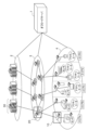
- FIG. 1 is a diagram showing an environment adaptive software system including an offload server 1 according to this embodiment.
- the environmentally adaptive software system according to this embodiment is characterized by including an offload server 1 in addition to the configuration of conventional environmentally adaptive software.
- the offload server 1 is an offload server that offloads specific processing of an application to an accelerator.
- the offload server 1 is also communicatively connected to each device located in three layers, namely, a cloud layer 2, a network layer 3, and a device layer 4.
- a data center 30 is disposed in the cloud layer 2
- a network edge 20 is disposed in the network layer 3
- a gateway 10 is disposed in the device layer 4.
- the environment-adaptive software system including the offload server 1 achieves efficiency by appropriately allocating functions and offloading processing in each of the device layer, network layer, and cloud layer. Mainly, efficiency is achieved by allocating functions to appropriate locations in the three layers for processing, and by offloading functional processing such as image analysis to heterogeneous hardware such as GPUs and FPGAs.
- FIG. 2 is a functional block diagram showing an example of the configuration of the offload server 1 according to an embodiment of the present invention.
- the offload server 1 is a device that executes environment-adaptive software processing. As one form of this environment-adaptive software, the offload server 1 automatically offloads specific processing of an application to an accelerator ( ⁇ automatic offload>). In addition, the offload server 1 can be connected to an emulator.
- the offload server 1 includes a control unit 11, an input/output unit 12, a memory unit 13, and a verification machine 14 (accelerator verification device).
- the input/output unit 12 is composed of a communication interface for sending and receiving information between each device, etc., and an input/output interface for sending and receiving information between input devices such as a touch panel or keyboard, and output devices such as a monitor.
- the storage unit 13 is configured with a hard disk, a flash memory, a RAM (Random Access Memory), or the like.
- the memory unit 13 stores a code pattern DB 131, an equipment resource DB 132, and a test case DB (Test case database) 133, and also temporarily stores programs (offload programs) for executing each function of the control unit 11 and information necessary for the processing of the control unit 11 (for example, an intermediate language file (Intermediate file) 134).
- the test case DB 133 stores performance test items.
- the test case DB 133 stores information for performing tests to measure the performance of an application to be accelerated.
- the test items are sample images and the test items for executing the images.
- the verification machine 14 includes a CPU (Central Processing Unit), a GPU, and an FPGA (accelerator) as a verification environment for the environment adaptive software.
- the offload server 1 is configured to include the verification machine 14, but the verification machine 14 may be located outside the offload server 1.
- the control unit 11 is an automatic offloading function that controls the entire offload server 1.
- the control unit 11 is realized, for example, by a CPU (not shown) that expands a program (offload program) stored in the memory unit 13 into RAM and executes it.
- the control unit 11 includes an application code specification unit (Specify application code) 111, an application code analysis unit (Analyze application code) 112, a PLD processing specification unit 113, an arithmetic strength calculation unit 114, a PLD processing pattern creation unit 115, a performance measurement unit 116, an executable file creation unit 117, a production environment deployment unit (Deploy final binary files to production environment) 118, a performance measurement test extraction execution unit (Extract performance test cases and run automatically) 119, a request processing load analysis unit 120 (processing load analysis unit), a representative data selection unit 121, an improvement degree calculation unit 122, a reconfiguration proposal unit 123, and a user provision unit (Provide price and performance to a user to judge) 124.
- the application code designation unit 111 designates the input application code. Specifically, the application code designation unit 111 identifies the processing function (image analysis, etc.) of the service provided to the user.
- the application code analysis unit 112 analyzes the source code of the processing function and understands the structure of loop statements, FFT library calls, and the like.
- the PLD processing specification unit 113 identifies loop statements (repetitive statements) in the application, and for each identified loop statement, creates and compiles a plurality of offload processing patterns specified in OpenCL for pipeline processing and parallel processing in the PLD.
- the PLD processing specification unit 113 includes an offloadable area extraction unit (Extract offloadable area) 113a and an intermediate language file output unit (Output intermediate file) 113b.
- the offload range extraction unit 113a identifies processes that can be offloaded to the FPGA, such as loop statements and FFTs, and extracts the intermediate language corresponding to the offloaded process.
- the intermediate language file output unit 113b outputs the extracted intermediate language file 134.
- Intermediate language extraction is not a one-time process, but is repeated to try and optimize execution in order to search for an appropriate offload area.
- the arithmetic intensity calculation unit 114 calculates the arithmetic intensity of a loop statement of an application using an arithmetic intensity analysis tool such as the ROSE Framework (registered trademark).
- the arithmetic intensity is the number of floating point numbers (FN) executed during program execution divided by the number of bytes accessed to the main memory (FN operations/memory access).
- Arithmetic strength is an index that increases with the number of calculations and decreases with the number of accesses, and a process with high arithmetic strength is a heavy process for a processor. Therefore, an arithmetic strength analysis tool is used to analyze the arithmetic strength of a loop statement.
- the PLD processing pattern creation unit 115 narrows down the offload candidates to loop statements with high arithmetic strength.
- the PLD processing pattern creation unit 115 Based on the arithmetic strength calculated by the arithmetic strength calculation unit 114, the PLD processing pattern creation unit 115 narrows down loop statements whose arithmetic strength is higher than a predetermined threshold (hereinafter, appropriately referred to as high arithmetic strength) as offload candidates, and creates a PLD processing pattern. In addition, as a basic operation, the PLD processing pattern creation unit 115 creates a PLD processing pattern that excludes loop statements (repetitive statements) that cause a compilation error from being offloaded, and specifies whether or not to perform PLD processing for repetitive statements that do not cause a compilation error.
- a predetermined threshold hereinafter, appropriately referred to as high arithmetic strength
- Loop count measurement function As the loop count measurement function, the PLD processing pattern creation unit 115 uses a profiling tool to measure the number of loops in an application and narrows down the loop statements that have high arithmetic strength and a loop count greater than a predetermined number (hereinafter, appropriately referred to as a high loop count). To grasp the loop count, GNU Coverage's gcov or the like is used. Known profiling tools include "GNU Profiler (gprof)" and "GNU Coverage (gcov)". Either may be used since both can investigate the number of times each loop is executed.
- a profiling tool is used to measure the number of loops in order to detect loops that have a large number of loops and a high load.
- the level of arithmetic strength indicates whether a process is suitable for offloading to an FPGA, and the number of loops x arithmetic strength indicates whether the load associated with offloading to an FPGA is high.
- the PLD processing pattern creation unit 115 creates (OpenCL) OpenCL for offloading each of the narrowed-down loop statements to the FPGA as the OpenCL creation function. That is, the PLD processing pattern creation unit 115 compiles OpenCL for offloading the narrowed-down loop statements.
- the PLD processing pattern creation unit 115 also creates a list of loop statements that have been measured and have higher performance than the CPU, and combines the loop statements in the list to create OpenCL for offloading.
- the PLD processing pattern creation unit 115 converts the loop statements into a high-level language such as OpenCL.
- the CPU processing program is divided into a kernel (FPGA) and a host (CPU) according to the grammar of the high-level language such as OpenCL.
- FPGA kernel
- CPU host
- OpenCL the high-level language
- the grammar of OpenCL For example, when one of ten for statements is to be processed by the FPGA, that one is extracted as a kernel program and described according to the grammar of OpenCL. An example of the grammar of OpenCL will be described later.
- techniques for further increasing speed can be incorporated.
- techniques for increasing speed using FPGAs include local memory cache, stream processing, multiple instantiation, loop unrolling, merging nested loop statements, memory interleaving, etc. These are often used as techniques for increasing speed, although they may not be absolutely effective for some loop statements.
- a kernel created according to the OpenCL C language syntax is executed on a device (e.g., FPGA) by a program created on the host (e.g., CPU) side using the OpenCL C language runtime API.
- the part where the kernel function hello() is called from the host side is to call clEnqueueTask(), which is one of the OpenCL runtime APIs.
- the basic flow of OpenCL initialization, execution, and termination described in the host code consists of the following steps 1 to 13. Of these steps 1 to 13, steps 1 to 10 are the procedure (preparation) until the kernel function hello() is called from the host side, and step 11 is the execution of the kernel.
- Platform Identification The platform on which OpenCL runs is identified using the function clGetPlatformIDs() that provides platform identification functionality defined in the OpenCL runtime API.
- Device Identification A device such as a GPU to be used on the platform is identified using a function clGetDeviceIDs() that provides a device identification function defined in the OpenCL runtime API.
- Context Creation An OpenCL context that serves as an execution environment for running OpenCL is created using the function clCreateContext() that provides a context creation function defined in the OpenCL runtime API.
- a command queue is created in preparation for controlling a device using the clCreateCommandQueue() function, which provides the command queue creation functionality defined in the OpenCL runtime API.
- the host issues commands to the device (such as issuing kernel execution commands and memory copy commands between the host and device) through the command queue.
- Creating a memory object A memory object that allows the host to reference the memory object is created using the clCreateBuffer() function, which provides the functionality for allocating memory on a device defined in the OpenCL runtime API.
- the execution of the kernel executed on the device is controlled by the host program. For this reason, the host program must first load the kernel program.
- the kernel program includes binary data created by the OpenCL compiler and source code written in the OpenCL C language. This kernel file is loaded (description omitted). Note that the OpenCL runtime API is not used when loading the kernel file.
- Creating a Program Object In OpenCL, a kernel program is recognized as a program project. This procedure is called creating a program object. Create a program object that allows the host to reference the memory object by using the function clCreateProgramWithSource(), which provides the program object creation function defined in the OpenCL runtime API. When creating a program object from a compiled binary sequence of a kernel program, use clCreateProgramWithBinary().
- a kernel object is created using the function clCreateKernel(), which provides the kernel object creation function defined in the OpenCL runtime API. Since one kernel object corresponds to one kernel function, the name of the kernel function (hello) is specified when creating the kernel object. Also, if multiple kernel functions are written as one program object, one kernel object corresponds one-to-one to one kernel function, so clCreateKernel() is called multiple times.
- Kernel arguments are set using the function clSetKernel(), which provides the functionality for providing arguments to the kernel defined in the OpenCL runtime API (passing values to arguments held by the kernel function). After the above steps 1 to 10 are completed, the process moves to step 11, where the host executes the kernel on the device.
- Kernel Execution Kernel execution (submission to the command queue) is an action on the device, so it is a queuing function for the command queue.
- a command to execute the kernel hello on the device is queued using a function clEnqueueTask() that provides a kernel execution function defined in the OpenCL runtime API. After the command to execute the kernel hello is queued, it will be executed on an executable computing unit on the device.
- Reading from a memory object Data is copied from the device memory area to the host memory area using the function clEnqueueReadBuffer(), which provides the function of copying data from device memory to host memory defined in the OpenCL runtime API. Data is also copied from the host memory area to the device memory area using the function clEnqueueWrightBuffer(), which provides the function of copying data from the host to host memory. Note that these functions act on the device, so the copy command is queued in the command queue once before data copying begins.
- the PLD processing pattern creation unit 115 precompiles the created OpenCL and calculates the amount of resources to be used ("first resource amount calculation").
- the PLD processing pattern creation unit 115 calculates resource efficiency based on the calculated arithmetic strength and resource amount, and selects c loop statements whose resource efficiency is higher than a predetermined value from each loop statement based on the calculated resource efficiency.
- the PLD processing pattern creation unit 115 calculates the amount of resources to be used by precompiling the combined offload OpenCL ("second resource amount calculation").
- the amount of resources may be calculated by adding up the amount of resources used in precompiling before the first measurement without precompiling.
- the performance measurement unit 116 compiles the created application of the PLD processing pattern, places it on the verification machine 14, and executes the processing for performance measurement when offloaded to the PLD.
- the performance measurement unit 116 includes a binary file deployment unit 116a.
- the binary file deployment unit 116a deploys an executable file derived from an intermediate language on the verification machine 14 including an FPGA.
- the performance measurement unit 116 executes the placed binary file, measures the performance when offloaded, and returns the performance measurement results to the offload range extraction unit 113a.
- the offload range extraction unit 113a extracts another PLD processing pattern, and the intermediate language file output unit 113b attempts to measure performance based on the extracted intermediate language (see symbol aa in Figure 3 below).
- the PLD processing pattern creation unit 115 narrows down loop statements with high resource efficiency, and compiles OpenCL that offloads the loop statements narrowed down by the executable file creation unit 117.
- the performance measurement unit 116 measures the performance of the compiled program ("first performance measurement").
- the PLD processing pattern creation unit 115 creates a list of loop statements that have been measured and have higher performance than the CPU.
- the PLD processing pattern creation unit 115 creates an OpenCL for offloading by combining the loop statements in the list.
- the PLD processing pattern creation unit 115 precompiles the combined offload OpenCL and calculates the amount of resources to be used. Note that the sum of the resource amounts in pre-compilation before the first measurement may be used without pre-compilation.
- the executable file creation unit 117 compiles the combined offload OpenCL, and the performance measurement unit 116 measures the performance of the compiled program ("second performance measurement").
- the executable file creation unit 117 selects a PLD processing pattern with the highest processing performance from among a plurality of PLD processing patterns based on the performance measurement results repeated a predetermined number of times, and compiles the PLD processing pattern with the highest processing performance to create an executable file.
- the production environment deployment unit 118 deploys the created executable file in the production environment for the user ("Deployment of final binary file in production environment").
- the production environment deployment unit 118 determines a pattern that specifies the final offload area, and deploys it to the production environment for the user.
- the performance measurement test extraction execution unit 119 After arranging the executable file, the performance measurement test extraction execution unit 119 extracts performance test items from the test case DB 133 and executes the performance tests. After arranging the executable file, the performance measurement test extraction execution unit 119 extracts performance test items from the test case DB 133 and automatically executes the extracted performance tests in order to show the performance to the user.
- the request processing load analysis unit 120 analyzes the request processing load of representative commercial data (data that is actually used by users).
- the request processing load analysis unit 120 calculates the actual processing time and the total number of uses from the usage history of each application for a specified period.
- the request processing load analysis unit 120 acquires request data for a certain period of time from the top-loaded applications, sorts the data sizes into fixed size groups, and creates a frequency distribution.
- the representative data selection unit 121 identifies the application with the highest processing load analyzed by the request processing load analysis unit 120, and selects representative data from the request data when the application is used. Specifically, the representative data selection unit 121 selects one piece of data from the actual request data that corresponds to the most frequent value Mode of the data size frequency distribution analyzed by the request processing load analysis unit 120, and selects it as the representative data.
- the improvement degree calculation unit 122 determines a new offload pattern (a new offload pattern found in the verification environment) based on the representative data selected by the representative data selection unit 121 by executing the application code analysis unit 112, the PLD processing specification unit 113, the arithmetic strength calculation unit 114, the PLD processing pattern creation unit 115, the performance measurement unit 116, and the executable file creation unit 117, and calculates the performance improvement effect by comparing the processing time and usage frequency of the determined new offload pattern with the processing time and usage frequency of the current offload pattern.
- the improvement calculation unit 122 measures the processing time of the current offload pattern and multiple new offload patterns, and calculates the performance improvement effect based on the commercial usage frequency according to (actual processing reduction time in the verification environment) x (commercial environment usage frequency).
- the reconfiguration proposing unit 123 proposes PLD reconfiguration when the performance improvement effect is equal to or greater than a predetermined threshold.
- the user providing unit 124 presents information such as price and performance based on the performance test results to the user ("Providing information such as price and performance to the user").
- the test case DB 133 stores data for automatically conducting tests to measure the performance of applications.
- the user providing unit 124 presents to the user the results of executing the test data in the test case DB 133 and the price of the entire system determined from the unit prices of the resources used in the system (virtual machines, FPGA instances, GPU instances, etc.). The user decides whether to start charging for the service based on the presented information such as price and performance.
- the offload server 1 configured as above will now be described.
- the offload server 1 is characterized in that it executes reconfiguration after the start of operation of the FPGA logic.
- the ⁇ automatic offload processing> executed by the offload server 1 as a form of environment adaptive software is the same before the start of operation and in the reconfiguration after the start of operation. That is, the automatic offload processing of the offload server 1 shown in FIG. 3 is the same before the start of operation and in the reconfiguration after the start of operation, but the difference is that the data handled before the start of operation is assumed use data, whereas the data handled in the reconfiguration after the start of operation is data actually used commercially (commercial representative data).
- the offload server 1 of this embodiment is an example in which an elemental technology of environment adaptive software is applied to FPGA automatic offloading of user application logic.
- Fig. 3 is a diagram showing the automatic offload processing of the offload server 1.
- the ⁇ automatic offload processing> in Fig. 3 is the same before the start of operation and in the reconfiguration after the start of operation.
- the offload server 1 is applied to the elemental technology of the environment adaptive software.
- the offload server 1 has a control unit (automatic offload function unit) 11 that executes the environment adaptive software processing, a code pattern DB 131, a facility resource DB 132, a test case DB 133, an intermediate language file 134, and a verification machine 14.
- the offload server 1 obtains the application code 130 used by the user.
- OpenIoT resources 15 which are a commercial environment, such as various devices 151, devices with CPU-GPU 152, devices with CPU-FPGA 153, and devices with CPU 154.
- the offload server 1 automatically offloads functional processing to the accelerators of the devices with CPU-GPU 152 and devices with CPU-FPGA 153.
- the offload server 1 executes environment-adaptive software processing by linking platform functions consisting of a code pattern DB 131, equipment resource DB 132, and test case DB 133 with the environment-adaptive functions of the commercial environment and verification environment provided by the business operator.
- Step S11 Specify application code>
- the application code designation unit 111 identifies a processing function (image analysis, etc.) of a service provided to a user. Specifically, the application code designation unit 111 designates an input application code.
- Step S12 Analyze application code>
- the application code analysis unit 112 analyzes the source code of the processing function and grasps the structures of loop statements, FFT library calls, and the like.
- Step S21 Extract offloadable area>
- the PLD processing specification unit 113 specifies loop statements (repetitive statements) of the application, specifies parallel processing or pipeline processing in the FPGA for each repetitive statement, and compiles it with a high-level synthesis tool.
- the offload range extraction unit 113a specifies processing that can be offloaded to the FPGA, such as loop statements, and extracts OpenCL as an intermediate language corresponding to the offload processing.
- Step S22 Output intermediate file: Output of intermediate language file>
- the intermediate language file output unit 113b (see FIG. 2) outputs the intermediate language file 134.
- the intermediate language extraction is not a one-time process, but is repeated to try and optimize the execution for an appropriate offload area search.
- Step S23 Compile error: PLD processing pattern creation>
- the PLD processing pattern creation unit 115 creates a PLD processing pattern that excludes loop statements that cause a compilation error from being offloaded, and specifies whether or not to perform FPGA processing for repetitive statements that do not cause a compilation error.
- Step S31 Deploy binary files: Placement of executable files>
- the binary file placement unit 116a (see FIG. 2) deploys an executable file derived from the intermediate language to the FPGA-equipped verification machine 14.
- the binary file placement unit 116a starts the placed file, executes assumed test cases, and measures the performance when offloaded.
- Step S32 Measure performances: Measure performance for appropriate pattern search>
- the performance measurement unit 116 executes the arranged file and measures the performance when offloaded. In order to determine the area to be offloaded more appropriately, the performance measurement result is returned to the offload range extraction unit 113a, which extracts another pattern.
- the intermediate language file output unit 113b then attempts performance measurement based on the extracted intermediate language (see symbol aa in FIG. 3).
- the performance measurement unit 116 repeats the performance measurement in the verification environment and finally determines the code pattern to be deployed.
- the control unit 11 repeatedly executes steps S12 to S23.
- the automatic offload function of the control unit 11 can be summarized as follows. That is, the PLD processing specification unit 113 identifies the loop statements (repeated statements) of the application, and for each repeated statement, specifies parallel processing or pipeline processing in the FPGA using OpenCL, and compiles it using a high-level synthesis tool.
- the PLD processing pattern creation unit 115 creates a PLD processing pattern that excludes loop statements that generate compilation errors from offloading targets, and specifies whether or not to perform PLD processing for loop statements that do not generate compilation errors.
- the binary file placement unit 116a then compiles the application of the corresponding PLD processing pattern, places it on the verification machine 14, and the performance measurement unit 116 executes the performance measurement processing on the verification machine 14.
- the execution file creation unit 117 selects a pattern with the highest processing performance from a plurality of PLD processing patterns based on the performance measurement results repeated a predetermined number of times, and compiles the selected pattern to create an execution file.
- Step S41 Determining resource size> The control unit 11 determines the resource size (see symbol bb in FIG. 3).
- Step S51 Selection of an appropriate placement location>
- the control unit 11 refers to the facility resource DB 132 and selects an appropriate location for placement.
- Step S61 Deploy final binary files to production environment>
- the production environment deployment unit 118 determines a pattern that specifies the final offload area, and deploys it to the production environment for the user.
- Step S62 Extract performance test cases and run automatically: Extract test cases and check normality>
- the performance measurement test extraction execution unit 119 extracts performance test items from the test case DB 133 and automatically executes the extracted performance tests in order to show the performance to the user.
- Step S63 Provide price and performance to a user to judge: Present price and performance to a user to judge whether to start using the service>
- the user providing unit 124 provides the user with information on price, performance, etc., based on the performance test results. The user determines whether to start using the service for which a fee is charged, based on the provided information on price, performance, etc.
- steps S11 to S63 are assumed to be performed in the background while the user is using the service, for example, during the first day of trial use.
- the processing performed in the background may only target GPU/FPGA offloading.
- control unit 11 of the offload server 1 extracts the area to be offloaded from the source code of the application used by the user and outputs an intermediate language to offload functional processing (steps S11 to S23).
- the control unit 11 places and executes the executable file derived from the intermediate language on the verification machine 14, and verifies the offloading effect (steps S31 to S32). After repeating the verification and determining an appropriate offload area, the control unit 11 deploys the executable file in the production environment that will actually be provided to the user, and provides it as a service (steps S41 to S63).
- the code analysis described above uses a syntax analysis tool such as Clang to analyze application code. Since code analysis requires analysis that assumes the device to be offloaded, it is difficult to generalize. However, it is possible to grasp the code structure, such as loop statements and variable reference relationships, and to grasp that a functional block performs FFT processing, or that a library that performs FFT processing is being called. It is difficult for the offload server to automatically determine the functional block. This can also be grasped by using a similar code detection tool such as Deckard to determine the similarity.
- Clang is a tool for C/C++, but it is necessary to select a tool that matches the language to be analyzed.
- offloading application processing consideration must be given to the offload destination for each GPU, FPGA, IoT GW, etc.
- Steps S11 and S12 in FIG. 3 Code analysis Steps S21 to S23 in FIG. 3: Extraction of offloadable parts Steps S31 to S32 in FIG. 3: Search for suitable offload parts Step S41 in FIG. 3: Resource amount adjustment Step S51 in FIG. 3: Placement location adjustment Steps S61 to S63 in FIG. 3: Executable file placement and operation verification
- steps S11 to S63 are required before the application can be put into operation, and involve code conversion, resource adjustment, placement location adjustment, and verification.
- the offload server 1 executes reconfiguration of the FPGA logic after the operation starts.
- the usage characteristics are analyzed and necessary reconfiguration is performed.
- the reconfiguration targets are code conversion, adjustment of resource amount, and adjustment of placement location, just like before the start of operation.
- Reconfiguration may involve offloading different loop statements within the same application, or it may involve offloading a different application.
- Dynamic reconfiguration is a technology in which the circuit configuration is changed while the FPGA is running, and the downtime required for reconfiguration is on the order of milliseconds.
- static reconfiguration is a technology in which the FPGA is stopped before changing the circuit configuration, and the downtime is on the order of one second. Whether to use dynamic or static reconfiguration depends on the impact of downtime on the user, and the reconfiguration method provided by the FPGA manufacturer can be selected. However, because downtime occurs with both methods and rewriting to a different logic requires testing to confirm operation, reconfiguration should not be performed frequently, and restrictions should be set, such as only proposing it when the effect is above a threshold.
- the reconfiguration under consideration will begin with an analysis of request trends over a certain period of time (e.g., one month).
- the request trends will be analyzed to determine whether there are any requests with a higher or equal processing load than the currently offloaded applications.
- an optimization trial of FPGA offloading will be performed in a verification environment ( Figure 3) using data that is actually used commercially (data actually used by users) rather than expected usage data.
- Whether the new offloading pattern found through verification is a sufficient improvement over the current offloading pattern is determined by whether the calculation results of processing time and usage frequency exceed or fall below a threshold. If the calculation results of processing time and usage frequency exceed the threshold, a reconfiguration is proposed to the user. After the user agrees, the commercial environment is reconfigured, but the reconfiguration is done while minimizing the impact on the user as much as possible. Furthermore, if the calculation results of processing time and usage frequency are below the threshold, no reconfiguration is proposed to the user.
- Step S71 the request processing load analysis unit 120 analyzes the request processing load of data actually used by a user. Note that a detailed flow of the commercial request data history analysis process will be described later with reference to FIG.
- step S72 the representative data selection unit 121 extracts an offload pattern for accelerating the test cases of the commercial representative data for the multiple high-load applications through the verification environment measurement. Specifically, the representative data selection unit 121 selects one piece of actual request data corresponding to the most frequent value Mode of the data size frequency distribution analyzed by the request processing load analysis unit 120 as the representative data. In the above steps S71 and S72, a high-load application is selected.
- step S73 the improvement calculation unit 122 determines a new offload pattern (a new offload pattern found in the verification environment) based on the representative data selected by the representative data selection unit 121 by executing the application code analysis unit 112, the PLD processing specification unit 113, the arithmetic strength calculation unit 114, the PLD processing pattern creation unit 115, the performance measurement unit 116, and the executable file creation unit 117, and calculates the performance improvement effect by comparing the processing time and usage frequency of the determined new offload pattern with the processing time and usage frequency of the current offload pattern.
- the improvement calculation unit 122 measures the processing time of the current offload pattern and the multiple extracted new offload patterns, and determines the performance improvement effect based on the commercial usage frequency. Specifically, the improvement calculation unit 122 calculates (actual processing time reduced in the verification environment) x (frequency of use of the commercial environment) ... formula (1) for the current offload pattern in a test case with commercial representative data. Then, the improvement calculation unit 122 calculates (actual processing time reduced in the verification environment) x (frequency of use of the commercial environment) ... formula (2) for the multiple new offload patterns. Note that the detailed flow of the commercial representative data extraction process will be described later in Figure 6.
- step S73 for applications that have been offloaded to the FPGA, the improvement coefficient is multiplied to calculate what would happen if the application was not offloaded, and the comparison is made after correcting for CPU processing only. Also, when selecting representative data, the most frequent data size mode is used, since the average data size may differ significantly from the data actually used.
- the reconfiguration proposal unit 123 determines whether to propose a reconfiguration based on whether the performance improvement effect of the new offload pattern is equal to or greater than a predetermined threshold value of the current offload pattern. Specifically, the reconfiguration proposal unit 123 obtains the calculation result of formula (2)/the calculation result of formula (1) for multiple offload patterns. The reconfiguration proposal unit 123 then checks whether the calculation result of formula (2)/the calculation result of formula (1) is equal to or greater than a predetermined threshold value, and proposes a reconfiguration if the calculation result of formula (2)/the calculation result of formula (1) is equal to or greater than the predetermined threshold value, and does nothing if it is less than the predetermined threshold value (does not propose a reconfiguration).
- step S75 the reconfiguration suggestion unit 123 suggests to the contracted user that they perform FPGA reconfiguration, and receives an OK/NG response from the contracted user regarding the execution of FPGA reconfiguration.
- step S76 the control unit 11 performs the static reconfiguration by starting another OpenCL in the commercial environment, and ends the processing of this flow. Specifically, the control unit 11 first compiles a new offload pattern. Next, the control unit 11 stops the operation of the current offload pattern and starts the operation of the new offload pattern.
- FIG. 5 is a detailed flowchart of the commercial request data history analysis process, which is a subroutine of step S71 in FIG.
- the request processing load analysis unit 120 calculates the actual processing time and the total number of uses from the usage history of each application over a certain period (long period; for example, one month). However, for applications that have been offloaded to FPGA, the processing time that would have been taken if the application had not been offloaded is provisionally calculated. From the test history of the assumed usage data before the start of operation, an improvement coefficient is calculated by dividing the actual processing time when only CPU processing is performed by the actual processing time and the actual processing time when offloaded to FPGA. The request processing load analysis unit 120 determines the sum of the values obtained by multiplying the actual processing time by the improvement coefficient as the total processing time to be used for comparison.
- step S82 the request processing load analysis unit 120 compares the total actual processing time for all applications.
- step S83 the request processing load analysis unit 120 sorts the requests in order of total actual processing time, and identifies the applications with the highest processing time loads.
- step S84 the request processing load analysis unit 120 acquires request data for a certain period (short period: 12 hours, etc.) of the top-loaded applications, sorts the data sizes into certain sizes, creates a frequency distribution, and returns to step S71 in FIG. 4.
- FIG. 6 is a detailed flow chart of the commercial representative data extraction process, which is a subroutine of step S73 in FIG.
- the improvement calculation unit 122 selects a predetermined number (four in this example) of "for" statements with high arithmetic strength from among the high-load applications.
- step S92 the improvement calculation unit 122 creates 4OpenCL that offloads four for statements, precompiles it, calculates the resource usage rate, and selects three for statements with high arithmetic strength/resource usage rate. As a result, 3OpenCL that offloads three for statements is selected.
- step S93 the improvement calculation unit 122 measures the performance of three OpenCLs using representative data. For example, the improvement calculation unit 122 creates an OpenCL that combines the top two performance-ranked for statements and measures the performance in the same way.
- step S94 the improvement calculation unit 122 determines the fastest off-load pattern among the four measurements as the solution and returns to step S72 in FIG. 4.
- the target application is a C/C++ language application
- the FPGA is an Intel PAC D5005 (Intel is a registered trademark) (Intel Stratix 10 GX FPGA).
- the compiling machine is a DELL EMC PowerEdge R740 (DELL is a registered trademark) (CPU: Intel Xeon Bronze 3206R x 2, RAM: 32GB RDIMM x 4).
- FPGA processing uses Intel Acceleration Stack Version 2.0 ("Intel” is a registered trademark) (Intel FPGA SDK for OpenCL, Intel Quartus Prime).
- the Intel Acceleration Stack enables high-level synthesis (HLS: High Level Synthesis) that interprets not only standard OpenCL but also Intel-specific ⁇ #pragmas.
- HLS High Level Synthesis
- the Intel Acceleration Stack also interprets OpenCL code that describes the kernel program to be processed by the FPGA and the host program to be processed by the CPU.
- the Intel Acceleration Stack outputs information such as resource amounts and performs FPGA wiring work, enabling it to operate on the FPGA.
- the LLVM/Clang 6.0 syntax analysis library (libClang (registered trademark) python binding) is used for C/C++ language syntax analysis.
- arithmetic strength and loop count are used to narrow down for statements.
- the ROSE compiler framework 0.9 is used to analyze arithmetic strength
- the profiler gcov is used to analyze loop counts.
- request data for a certain period is analyzed to determine the application with the highest load, and actual request data for the certain period (short period) of the application is obtained.
- the number of top load applications and the fixed period can be set by the operator, allowing for some flexibility.
- the above long period is assumed to be a long span of one month or more.
- the above short period is assumed to be a short span of 12 hours, for example.
- the actual processing time of the application and the number of times it is used are totaled, and this is obtained using the Linux (registered trademark) time command.
- the time command logs the actual elapsed time of the application, so the desired value can be calculated from the number of times logged and the total time.
- step S72 in FIG. 4 real request data for a certain period (short period) of high-load applications is sorted by a certain size to create a frequency distribution.
- the number of bins in the frequency distribution is determined by Sturges' rule.
- Sturges' rule states that when the number of times an application is used is n (n is any natural number), it is appropriate to set the number of bins to 1 + log 2 n. To use Sturges' rule, it is necessary to determine the number of bins, select the most frequent bin, and then select one representative data from the most frequent bin. In addition, when selecting representative data, data whose data size is closest to the median value of the bin is selected as the representative data.
- FPGA offloading is performed on the top-loaded application using the selected representative data in the same process as before operation started.
- the difference from before operation started is that the test cases used to measure performance are commercial representative data, rather than expected usage data.
- step S73 in FIG. 4 it is necessary to look at the improvement effect when the commercial environment is reconfigured to the new offload pattern. Since the reconfiguration has not yet been proposed by the user, verification must be performed on the verification environment server, but the improvement calculation unit 122 measures the improvement for one processing session using representative commercial data, and calculates the overall improvement degree using the frequency of commercial use. The improvement calculation unit 122 then compares the degree of effect when the commercial environment is reconfigured.
- the reconfiguration proposal unit 123 does not propose reconfiguration to the user. Since frequent reconfiguration proposals would be inconvenient for the user, the effect improvement threshold is set to a value sufficiently larger than 1x to suppress frequent reconfiguration proposals and to leave cases of truly effective reconfiguration.
- the reconfiguration threshold is a variably settable implementation, and is set to, for example, 1.5.
- the reconfiguration proposal unit 123 proposes reconfiguration to the user by adding information on price change or improvement effect.
- the information on price change or improvement effect is information on the price that will change as a result of reconfiguration, or information on how many times the improvement effect was in the verification environment even if there was no price change. This allows the contracted user to decide whether or not reconfiguration is advisable.
- the control unit 11 performs the reconfiguration using the static reconfiguration function of OpenCL.
- the static reconfiguration function is implemented in such a way that a downtime of about 1 second occurs. If it is desired to reduce the downtime to the order of ms, the reconfiguration may be performed using a dynamic reconfiguration function such as the dynamic partial reconfiguration function of Intel FPGA (registered trademark).
- the automatic offload operation (after operation has started) has been described above.
- FIG. 7 is a flowchart illustrating an outline of the operation of the offload server 1.
- the application code analysis unit 112 analyzes the source code of the application to be offloaded.
- the application code analysis unit 112 analyzes information on loop statements and variables according to the language of the source code.
- step S102 the PLD processing specification unit 113 identifies the loop statements and reference relationships of the application.
- the PLD processing pattern creation unit 115 narrows down candidates for whether or not to attempt FPGA offloading for the identified loop statements.
- Arithmetic strength is one indicator of whether or not offloading is effective for a loop statement.
- the arithmetic strength calculation unit 114 calculates the arithmetic strength of the loop statement of the application using an arithmetic strength analysis tool.
- the arithmetic strength is an index that increases with the number of calculations and decreases with the number of accesses. A process with high arithmetic strength is a heavy process for the processor.
- an arithmetic strength analysis tool is used to analyze the arithmetic strength of loop statements, and loop statements with high density are narrowed down to offloading candidates.
- the ROSE framework is used for the arithmetic strength analysis. Loops with a large number of loop counts also become heavy processes. The loop count is analyzed with a profiler, and loop statements with a large number of loop counts are also narrowed down to offloading candidates. gcov is used for loop count analysis.
- the PLD processing pattern creation unit 115 converts the target loop statement into a high-level language such as OpenCL, and first calculates the resource amount.
- the resource efficiency is set to arithmetic strength/resource amount or arithmetic strength x loop count/resource amount. Then, loop statements with high resource efficiency are further narrowed down as offload candidates.
- the CPU processing program is divided into the kernel (FPGA) and the host (CPU) according to the OpenCL grammar.
- step S104 the PLD processing pattern creation unit 115 measures the number of loops in the loop statements of the application using a profiling tool such as gcov or gprof.
- step S105 the PLD processing pattern creation unit 115 narrows down the loop statements to those with high arithmetic strength and a high number of loops.
- step S106 the PLD processing pattern creation unit 115 creates OpenCL for offloading each of the narrowed down loop statements to the FPGA.
- step S107 the PLD processing pattern creation unit 115 precompiles the created OpenCL and calculates the amount of resources to be used ("first resource amount calculation").
- step S108 the PLD processing pattern creation unit 115 narrows down the loop statements with high resource efficiency.
- step S109 the executable file creation unit 117 compiles OpenCL to offload the narrowed-down loop statements.
- step S110 the performance measurement unit 116 uses the user's usage data (data actually used by the user; commercial representative data) to measure the performance of the compiled program ("first performance measurement").
- step S111 the PLD processing pattern creation unit 115 creates a list of loop statements whose performance has been measured and whose performance has been improved compared to the CPU.
- step S112 the PLD processing pattern creation unit 115 creates an OpenCL for offloading by combining loop statements of the list.
- step S113 the PLD processing pattern creation unit 115 calculates the amount of resources to be used by precompiling with OpenCL for the combined offload ("calculating the amount of resources for the second time"). Note that it is also possible to use the sum of the amount of resources used in precompiling before the first measurement without precompiling. In this way, the number of times of precompiling can be reduced.
- step S114 the executable file creation unit 117 compiles OpenCL for the combined offload.
- step S115 the performance measurement unit 116 uses the user's usage data (data actually used by the user; commercial representative data) to measure the performance of the compiled program ("second performance measurement").
- step S116 the production environment deployment unit 118 selects the pattern with the best performance from the first and second measurements and ends the processing of this flow.
- FIG. 8 is a diagram showing an image of a search performed by the PLD processing pattern generating unit 115.
- the control unit (automatic offload function unit) 11 analyzes the application code 130 (see FIG. 3) used by the user, and checks whether or not for statements can be parallelized from the code patterns 141 of the application code 130, as shown in FIG. 8.
- the symbol a in FIG. 8 when four for statements are found from the code pattern 141, one digit is assigned to each for statement, in this case four digits of 1 or 0 are assigned to the four for statements.
- 1 is assigned when FPGA processing is performed
- 0 is assigned when FPGA processing is not performed (i.e. processing is performed by the CPU).
- Steps A to F in FIG. 9 are diagrams for explaining the flow from the C code to the search for the final OpenCL solution.
- the application code analysis unit 112 (see FIG. 2) performs syntax analysis of the "C code” shown in step A of FIG. 9 (see symbol b in FIG. 9), and the PLD processing specification unit 113 (see FIG. 2) identifies the "loop statement, variable information" shown in step B of FIG. 9 (see FIG. 8).
- the arithmetic strength calculation unit 114 performs an arithmetic intensity analysis on the identified "loop statement, variable information" using an arithmetic strength analysis tool.
- the PLD processing pattern creation unit 115 narrows down the offload candidates to loop statements with high arithmetic strength. Furthermore, the PLD processing pattern creation unit 115 performs a profiling analysis using a profiling tool (see symbol c in FIG. 9) to further narrow down the loop statements with high arithmetic strength and a high number of loops. Then, the PLD processing pattern creation unit 115 creates OpenCL for offloading each of the narrowed down loop statements to the FPGA (OpenCL conversion). Furthermore, when converting to OpenCL, we will introduce speed-up techniques such as code splitting and unrolling (see below).
- the PLD processing pattern creation unit 115 compiles OpenCL to offload the narrowed-down loop statements.
- the performance measurement unit 116 measures the performance of the compiled program ("first performance measurement"). Then, the PLD processing pattern creation unit 115 creates a list of loop statements whose performance has been measured and whose performance has been improved compared to the CPU. Thereafter, similarly, the resource amount is calculated, offload OpenCL compilation is performed, and the performance of the compiled program is measured.
- the executable file creation unit 117 compiles (main compiles) OpenCL to offload the narrowed-down loop statements.
- step E of Figure 9 refers to measuring the candidate loop statements individually, and then measuring the verification patterns for those combinations.
- FPGAs that can be used include Intel PAC with Intel Arria10 GX FPGA.
- Intel Acceleration Stack Intelligent FPGA SDK for OpenCL, Quartus Prime Version
- the Intel FPGA SDK for OpenCL is a high-level synthesis tool (HLS) that interprets standard OpenCL as well as Intel-specific #pragma directives.
- HLS high-level synthesis tool
- the OpenCL code that describes the kernel to be processed by the FPGA and the host program to be processed by the CPU is interpreted, information such as resource amounts is output, and wiring work for the FPGA is performed so that it can run on the FPGA.
- the code of the C/C++ application is first analyzed to discover for statements and to understand the program structure, such as variable data used within the for statements.
- the code of the C/C++ application is first analyzed to discover for statements and to understand the program structure, such as variable data used within the for statements.
- syntax analysis LLVM/Clang syntax analysis libraries, etc. can be used.
- an arithmetic strength analysis tool is executed to obtain an index of arithmetic strength determined by the number of calculations, the number of accesses, etc.
- the ROSE framework, etc. can be used for the arithmetic strength analysis. Only the loop statements with the highest arithmetic strength are targeted.
- a profiling tool such as gcov is used to obtain the loop count of each loop. The top a loop statements based on arithmetic strength x loop count are narrowed down to candidates.
- OpenCL code is generated for each loop statement with high arithmetic strength to be offloaded to the FPGA.
- the OpenCL code is divided into the relevant loop statement as the FPGA kernel and the rest as the CPU host program.
- a fixed number b of loop statement expansion may be performed as a speed-up technique. Loop statement expansion increases the amount of resources required, but is effective in increasing speed. Therefore, the number of expansions is limited to a fixed number b so that the amount of resources does not become excessive.
- the Intel FPGA SDK for OpenCL is used to precompile a number of OpenCL codes, and the amount of resources used, such as flip flops and look up tables, is calculated.
- the amount of resources used is displayed as a percentage of the total resource amount.
- the resource efficiency may be calculated by multiplying the number of loops. For each loop statement, c statements with the highest resource efficiency are selected.
- a pattern to be measured is created with c loop statements as candidates. For example, if the first and third loops are highly resource efficient, an OpenCL pattern is created to offload loop 1 and loop 3, and then compiled and performance is measured. If speed can be improved by offloading multiple single-loop statements (for example, if both loops 1 and 3 are fast), an OpenCL pattern for that combination is created, compiled, and performance is measured (for example, a pattern to offload both loops 1 and 3).
- the amount of resources used is also included in the combination. Therefore, if the amount does not fall within the upper limit, the combination pattern will not be created.
- performance is measured on a server equipped with an FPGA in the verification environment. To measure performance, sample processing specified by the application to be accelerated is performed. For example, in the case of a Fourier transform application, performance is measured by benchmarking the conversion process on sample data. In the implementation example, finally, the fastest pattern among the multiple measurement patterns is selected as the solution.
- the offload server 1 is realized by, for example, a computer 900 having a configuration as shown in Fig. 10.
- the verification machine 14 shown in Fig. 2 is located outside the offload server 1.
- FIG. 10 is a hardware configuration diagram showing an example of a computer 900 that realizes the functions of the offload server 1.
- the computer 900 has a CPU 910 , a RAM 920 , a ROM 930 , a HDD 940 , a communication interface (I/F) 950 , an input/output interface (I/F) 960 , and a media interface (I/F) 970 .
- the CPU 910 operates based on the programs stored in the ROM 930 or the HDD 940, and controls each component.
- the ROM 930 stores a boot program executed by the CPU 910 when the computer 900 starts up, and programs that depend on the hardware of the computer 900, etc.
- the HDD 940 stores the programs executed by the CPU 910 and the data used by such programs.
- the communication interface 950 receives data from other devices via the communication network 80 and sends it to the CPU 910, and transmits data generated by the CPU 910 to other devices via the communication network 80.
- the CPU 910 controls output devices such as a display and a printer, and input devices such as a keyboard and a mouse, via the input/output interface 960.
- the CPU 910 acquires data from the input devices via the input/output interface 960.
- the CPU 910 also outputs generated data to the output devices via the input/output interface 960.
- the media interface 970 reads a program or data stored in the recording medium 980 and provides it to the CPU 910 via the RAM 920.
- the CPU 910 loads the program from the recording medium 980 onto the RAM 920 via the media interface 970 and executes the loaded program.
- the recording medium 980 is, for example, an optical recording medium such as a DVD (Digital Versatile Disc) or a PD (Phasechangerewritable Disk), a magneto-optical recording medium such as an MO (Magneto Optical disk), a tape medium, a magnetic recording medium, or a semiconductor memory.
- the CPU 910 of the computer 900 executes programs loaded onto the RAM 920 to realize the functions of each part of the offload server 1.
- the HDD 940 stores data for each part of the offload server 1.
- the CPU 910 of the computer 900 reads and executes these programs from the recording medium 980, but as another example, these programs may be obtained from another device via the communication network 80.
- the offload server 1 includes an application code analysis unit 112 that analyzes the source code of an application, a PLD processing specification unit 113 that identifies loop statements in the application, and creates and compiles a plurality of offload processing patterns that specify pipeline processing and parallel processing in the PLD by OpenCL for each identified loop statement, an arithmetic strength calculation unit 114 that calculates the arithmetic strength of the loop statement of the application, a PLD processing pattern creation unit 115 that narrows down loop statements having an arithmetic strength higher than a predetermined threshold as offload candidates based on the arithmetic strength calculated by the arithmetic strength calculation unit 114 and creates a PLD processing pattern, a performance measurement unit 116 that compiles an application of the created PLD processing pattern, places it in the accelerator verification device 14, and executes a process for measuring performance when offloaded to the PLD, an execution file creation unit 117 that selects a PLD processing pattern with the highest processing performance from
- a representative data selection unit 121 that identifies an application having a high processing load analyzed by the request processing load analysis unit 120 and selects representative data from request data when the application is used; and a new offload pattern (a new offload pattern found in the verification environment) based on the representative data selected by the representative data selection unit 121, which is executed by an application code analysis unit 112, a PLD processing designation unit 113, an arithmetic strength calculation unit 114, a PLD processing pattern creation unit 115, a performance measurement unit 116, and an executable file creation unit 117.
- the representative data selection unit 121 determines a performance improvement effect by comparing the processing time and usage frequency of the new offload pattern determined based on the representative data, and calculates a performance improvement effect by comparing the processing time and usage frequency of the new offload pattern (a new offload pattern found in the verification environment) with the processing time and usage frequency of the current offload pattern, based on the representative data selected by the representative data selection unit 121; and a reconfiguration proposal unit 123 proposes PLD reconfiguration if the performance improvement effect is equal to or greater than a predetermined threshold.
- the offload server 1 can be reconfigured to a more appropriate logic according to the usage characteristics not only before operation begins but also after operation begins, thereby making it possible to improve the efficiency of resource utilization in a PLD (e.g., an FPGA) with limited resource amounts.
- a PLD e.g., an FPGA
- the offload server 1 can reconfigure the FPGA logic in response to changes in usage characteristics after the application has started operating, if there is a possibility that the data will deviate significantly from the data actually used after operation has started, for example, if the usage pattern after operation has started differs from what was initially expected and offloading other logic to the FPGA would improve performance, the FPGA logic can be reconfigured with minimal impact on the user. Note that reconfiguration may involve changing the offloading of a different loop statement in the same application, or changing the offloading of a different application. There are many targets for reconfiguration, such as GPUs, FPGA offload logic, resource amounts, and placement locations.
- the request processing load analysis unit 120 is characterized by calculating the actual processing time and the total number of uses from the usage history of each application for a specified period.
- the offload server 1 can analyze the request processing load of data actually being used by users from the usage history of each application over a certain period of time.
- the request processing load analysis unit 120 calculates an improvement coefficient from the test history of the assumed usage data before the start of operation by dividing the actual processing time with CPU processing only by the actual processing time with PLD offloading, and determines the sum of the values obtained by multiplying the improvement coefficient by the actual processing time as the total processing time to be used for comparison.
- the offload server 1 selects the top-loaded application, it can multiply the FPGA-offloaded application by the improvement coefficient, calculate the case where the application is not offloaded, and make a comparison by correcting to CPU processing only. Since the case where the application is not offloaded is corrected by multiplying by the improvement coefficient, a more accurate calculation of actual processing time is possible.
- the request processing load analysis unit 120 acquires request data for a specified period of time from the top-loaded applications, sorts the data sizes into fixed size groups to create a frequency distribution, and the representative data selection unit 130 selects one piece of actual request data that corresponds to the most frequent value Mode of the frequency distribution, and selects it as the representative data.
- the offload server 1 selects representative data
- the average data size may differ significantly from the actual data usage, but by using the most frequent data size mode, it is possible to select more appropriate representative data.
- the improvement calculation unit 122 measures the processing time of the current offload pattern and multiple new offload patterns, and calculates the performance improvement effect based on the commercial usage frequency according to (reduced actual processing time in the verification environment) x (usage frequency in the commercial environment).
- the offload server 1 can calculate (the actual processing time reduction in the verification environment) x (the frequency of use of the commercial environment) for multiple new offload patterns, and calculate (the actual processing time reduction in the verification environment) x (the frequency of use of the commercial environment) for the current offload pattern, and by dividing the former by the latter, it is possible to obtain a more accurate performance improvement effect using the two parameters of processing time and frequency of use.
- the present invention is an offload program for causing a computer to function as the above-mentioned offload server.
- the above-mentioned configurations, functions, processing units, processing means, etc. may be realized in hardware, in part or in whole, for example by designing them as integrated circuits. Further, the above-mentioned configurations, functions, etc. may be realized by software that causes a processor to interpret and execute programs that realize the respective functions. Information on the programs, tables, files, etc. that realize the respective functions can be stored in a memory, a recording device such as a hard disk or SSD (Solid State Drive), or a recording medium such as an IC (Integrated Circuit) card, SD (Secure Digital) card, or optical disc.
- a recording device such as a hard disk or SSD (Solid State Drive)
- a recording medium such as an IC (Integrated Circuit) card, SD (Secure Digital) card, or optical disc.
- a for statement is used as an example of a repetitive statement (loop statement), but other statements besides the for statement, such as a while statement or a do-while statement, are also included. However, a for statement that specifies the continuation conditions of the loop, etc., is more suitable.
Abstract
オフロードサーバ(1)は、実際にユーザが利用しているデータのリクエスト処理負荷を分析するリクエスト処理負荷分析部(120)と、分析した処理負荷が上位のアプリケーションを特定し、当該アプリケーション利用時のリクエストデータの中から代表データを選定する代表データ選定部(121)と、選定した代表データをもとに、新たなオフロードパターンをアプリケーションコード分析部(112)とPLD処理指定部(113)と算術強度算出部(114)とPLD処理パターン作成部(115)と性能測定部(116)と実行ファイル作成部(117)とを実行することにより定め、定めた新たなオフロードパターンの処理時間および利用頻度と、現在のオフロードパターンの処理時間および利用頻度とを比較して性能改善効果を計算する改善度計算部(122)と、性能改善効果が所定閾値以上の場合、PLD再構成を提案する再構成提案部(123)と、を備える。
Description
本発明は、機能処理をFPGA(Field Programmable Gate Array)等のアクセラレータに自動オフロードするオフロードサーバ、オフロード制御方法およびオフロードプログラムに関する。
クラウドレイヤでは、GPU(Central Processing Unit)やFPGA(Field Programmable Gate Array)等のヘテロジニアスなHW(ハードウェア)(以下、「ヘテロデバイス」と称する。)を備えたサーバが増えてきている。例えば、Microsoft(登録商標)社のBing検索においても、FPGAが利用されている。このように、ヘテロデバイスを活用し、例えば、行列計算等をGPUにオフロードしたり、FFT(Fast Fourier Transform)計算等の特定処理をFPGAにオフロードしたりすることで、高性能化を実現している。
ムーアの法則の減速予測から、CPU1コアの半導体集積度やクロック数を上げるだけでなく、コア数を増やすマルチコアCPU、GPU(Graphics Processing Unit)やFPGA等のヘテロジニアスなハードウェアが、通常のアプリケーション運用に用いられるようになっている。Microsoft(登録商標)社は、FPGAの検索利用等の取り組みをしている。また、Amazon(登録商標)社のクラウドでは、FPGAやGPUインスタンスを提供している。さらに、ヘテロジニアスなハードウェアとして、IoT(Internet of Things)機器等の小型デバイスの利用も増えている。
しかし、1コアのCPUでないヘテロジニアスなハードウェアを効率よく利用するためには、ハードウェアに応じたプログラム作成や設定が必要となり、大半の技術者にとっては、壁が高い。マルチコアCPUでは、OpenMP(Open Multi-Processing)、GPUではCUDA(Compute Unified Device Architecture)、FPGAではOpenCL(Open Computing Language)、IoT機器ではアセンブリ等の高度な知識が必要となってくることが多い。
ヘテロジニアスなハードウェアをより活用していくためには、高度な知識を持たない通常の技術者でも、それらを最大限活用できるようにするプラットフォームが必要である。技術者が通常のCPUと同様のロジックで処理を記述したソフトウェアを、分析して、配置先の環境(マルチコアCPU、GPU、FPGA等)にあわせて、適切に変換、設定を行い、環境に適応した動作をさせることを、プラットフォームが行うことが求められる。
GPUの単純な計算力を一般的計算にも用いるGPGPU(General Purpose GPU)が近年盛んになってきている。そのための環境としてNVIDIA(登録商標)は、CUDAを提供している。また、GPUだけに限定せずに、FPGA、GPU等のヘテロジニアスなハードウェアを共通的に扱う仕様としてはOpenCLがあり、多くのベンダがOpenCLに対応してきている。OpenCLやCUDAは、C言語の拡張を用いてプログラムを記述する。拡張記述として、カーネルと呼ばれるFPGA等とホストと呼ばれるCPUの間のメモリ情報の移行などを記述するが、オリジナルのC言語に比べてハードウェアの知識が必要と言われる。
OpenCLやCUDAの文法を理解していなくても、容易にGPU等のヘテロジニアスなハードウェアを用いることができるようにするため、下記取り組みがある。すなわち、ディレクティブでGPU処理等を行う行を指定して、ディレクティブに基づいてコンパイラが、GPUやマルチコアCPUのバイナリファイルを作成する。また、OpenMPやOpenACC等の仕様が、それを解釈実行するgccやPGI等のコンパイラを用いる。
OpenMPやOpenACC等を用いることで容易に、また、OpenCLやCUDA等を用いることでより細かく、FPGAやGPU、マルチコアCPUを利用できるようになっている。しかし、それらのハードウェアを利用することはできても、性能改善は容易ではないのが現状である。例えば、Intel(登録商標)コンパイラという、自動でCPUの複数のコアに処理を分配するコンパイラがある。Intelコンパイラ等は、自動化時は、プログラムのループの中で、並列処理可能なループを見つけ、複数のコアに処理を行わせている。しかし、データコピー等により、単に複数のコアでループを処理しても性能が改善しないことも多い。マルチコアCPUでなく、GPUやFPGAの際はメモリも異なるためより複雑である。性能改善には、OpenCLやCUDAを駆使してチューニングが必要である。また、gcc等を用いて適切なGPU処理箇所を試行錯誤で探索することが必要である。このように、ヘテロジニアスなハードウェアを用いた性能改善には、技術スキルや、試行錯誤の稼働が必要である。
ループ文のGPUオフロードとして、ループ文のGPU処理箇所探索を自動化する取り組みとして、進化計算手法であるGA(Genetic Algorithm:遺伝的アルゴリズム)を用いたオフロードが提案されている(非特許文献1)。
また、FPGAでは、コンパイルに長時間かかり、何度も測定することができないため、ループ文算術強度やオフロード時のFPGAリソース使用率をもとに、候補とするループ文を絞った後にOpenCL化して測定し適切なパターンを探索する手法が提案されている(非特許文献2)。
Y. Yamato, "Study and Evaluation of Improved Automatic GPU Offloading Method," International Journal of Parallel, Emergent and Distributed Systems, Taylor and Francis, DOI: 10.1080/17445760.2021.1941010, June 2021.
Y. Yamato, "Automatic Offloading Method of Loop Statements of Software to FPGA," International Journal of Parallel, Emergent and Distributed Systems, Taylor and Francis, DOI: 10.1080/17445760.2021.1916020, Apr. 2021.
従来技術において、ヘテロジニアスなハードウェアに対するオフロードは、手動での取組みが主流であり、自動オフロード方式は、非特許文献1,2に記載の技術にとどまる。
非特許文献1,2では、環境適応ソフトウェアのコンセプトについて、ループ文等のGPUやFPGA自動オフロード方式を検証している。
しかし、非特許文献1,2に記載の自動オフロード方式は、アプリケーションの運用開始前に変換や配置等の適応処理を行うことが前提となっており、運用開始後に利用特性変化等に応じて再構成することは想定されていない。すなわち、非特許文献1,2は、全てアプリケーションの運用開始前の技術であり、運用開始後の再構成については検討がされていない。
非特許文献1,2では、環境適応ソフトウェアのコンセプトについて、ループ文等のGPUやFPGA自動オフロード方式を検証している。
しかし、非特許文献1,2に記載の自動オフロード方式は、アプリケーションの運用開始前に変換や配置等の適応処理を行うことが前提となっており、運用開始後に利用特性変化等に応じて再構成することは想定されていない。すなわち、非特許文献1,2は、全てアプリケーションの運用開始前の技術であり、運用開始後の再構成については検討がされていない。
例えば、アプリケーションの運用開始前はSQLクエリが多い前提でSQL処理をアクセラレートするロジックをFPGAで構成していたとする。ところが、運用開始後(例えば、半年後)には、NoSQLクエリが多くなっていたため、NoSQL処理をアクセラレートするロジックのFPGAを再構成した方がよい場合等である。
このように、運用開始後に利用特性変化等に応じて再構成することは想定されていないという課題があった。
このような点に鑑みて本発明がなされたのであり、運用開始前だけでなく、運用開始後の利用特性に応じて、より適切なロジックに再構成することで、リソース量が限定されるPLD(例えば、FPGA)においてリソース利用の効率化を図ることを課題とする。
前記した課題を解決するため、アプリケーションの特定処理をPLD(Programmable Logic Device)にオフロードするオフロードサーバであって、アプリケーションのソースコードを分析するアプリケーションコード分析部と、前記アプリケーションのループ文を特定し、特定した各前記ループ文に対して、前記PLDにおけるパイプライン処理、並列処理をOpenCLで指定した複数のオフロード処理パターンにより作成してコンパイルするPLD処理指定部と、前記アプリケーションのループ文の算術強度を算出する算術強度算出部と、前記算術強度算出部が算出した算術強度をもとに、前記算術強度が所定の閾値より高いループ文をオフロード候補として絞り込み、PLD処理パターンを作成するPLD処理パターン作成部と、作成された前記PLD処理パターンの前記アプリケーションをコンパイルして、アクセラレータ検証用装置に配置し、前記PLDにオフロードした際の性能測定用処理を実行する性能測定部と、前記性能測定用処理による性能測定結果をもとに、複数の前記PLD処理パターンから最高処理性能のPLD処理パターンを選択し、最高処理性能の前記PLD処理パターンをコンパイルして実行ファイルを作成する実行ファイル作成部と、実際にユーザが利用しているデータのリクエスト処理負荷を分析する処理負荷分析部と、前記処理負荷分析部が分析したリクエスト処理負荷が上位のアプリケーションを特定し、当該アプリケーション利用時のリクエストデータの中から代表データを選定する代表データ選定部と、前記代表データ選定部が選定した代表データをもとに、新たなオフロードパターンを前記アプリケーションコード分析部と前記PLD処理指定部と前記算術強度算出部と前記PLD処理パターン作成部と前記性能測定部と前記実行ファイル作成部とを実行することにより定め、定めた新たなオフロードパターンの処理時間および利用頻度と、現在のオフロードパターンの処理時間および利用頻度とを比較して性能改善効果を計算する改善度計算部と、前記性能改善効果が所定閾値以上の場合、PLD再構成を提案する再構成提案部と、を備えることを特徴とするオフロードサーバとした。
本発明によれば、運用開始後の利用特性に応じて、より適切なロジックに再構成することができ、リソース量が限定されるPLD(例えば、FPGA)においてリソース利用の効率化を図ることができる。
次に、本発明を実施するための形態(以下、「本実施形態」と称する。)における、オフロードサーバ1等について説明する。
以下、明細書の説明において、PLD(Programmable Logic Device)として、FPGA(Field Programmable Gate Array)に適用した例について説明する。本発明は、プログラマブルロジックデバイス全般に適用可能である。
以下、明細書の説明において、PLD(Programmable Logic Device)として、FPGA(Field Programmable Gate Array)に適用した例について説明する。本発明は、プログラマブルロジックデバイス全般に適用可能である。
(背景説明)
[環境適応ソフトウェア]
本発明のオフロードサーバが実行する環境適応ソフトウェアは、下記の特徴を有する。すなわち、オフロードサーバは、環境適応ソフトウェアの実行により、一度記述したプログラムコードを、配置先の環境に存在するGPUやFPGA、マルチコアCPU等を利用できるように、変換、リソース設定、配置決定等を自動で行い、アプリケーションを高性能に動作させる。環境適応ソフトウェアの要素として、コードのループ文および機能ブロックを、GPU、FPGAに自動オフロードする方式、GPU等の処理リソース量を適切にアサインする方式がある。
[環境適応ソフトウェア]
本発明のオフロードサーバが実行する環境適応ソフトウェアは、下記の特徴を有する。すなわち、オフロードサーバは、環境適応ソフトウェアの実行により、一度記述したプログラムコードを、配置先の環境に存在するGPUやFPGA、マルチコアCPU等を利用できるように、変換、リソース設定、配置決定等を自動で行い、アプリケーションを高性能に動作させる。環境適応ソフトウェアの要素として、コードのループ文および機能ブロックを、GPU、FPGAに自動オフロードする方式、GPU等の処理リソース量を適切にアサインする方式がある。
<自動オフロード方式>
オフロードしたいアプリケーションは、多様である。また、映像処理のための画像分析、センサデータを分析するための機械学習処理等、計算量が多く、時間がかかるアプリケーションでは、ループ文による繰り返し処理が長時間を占めている。そこで、ループ文をFPGAに自動でオフロードすることで、高速化することがターゲットとして考えられる。
オフロードしたいアプリケーションは、多様である。また、映像処理のための画像分析、センサデータを分析するための機械学習処理等、計算量が多く、時間がかかるアプリケーションでは、ループ文による繰り返し処理が長時間を占めている。そこで、ループ文をFPGAに自動でオフロードすることで、高速化することがターゲットとして考えられる。
まず、ループ文をFPGA等の別ハードウェアに自動でオフロードする場合の基本的な課題として、下記がある。すなわち、コンパイラが「このループ文はFPGA等の別ハードウェアで処理できない」という制限を見つけることは可能であっても、「このループ文はFPGA等の別ハードウェアの処理に適している」という適合性を見つけることは難しいのが現状である。また、ループ文をFPGAに自動でオフロードする場合、一般的にループ回数が多いことや計算処理数等の算術強度が高いループの方が適しているとされている。しかし、実際にどの程度の性能改善になるかは、実測してみないと予測は困難である。そのため、ループ文をFPGA等の別ハードウェアにオフロードするという指示を手動で行い、性能測定を試行錯誤することが行われている。
そこで、実際に性能測定するパターンを絞ってからアクセラレータ検証環境に配置し、コンパイルしてFPGA実機で性能測定する回数を減らすことを想定する。
そこで、実際に性能測定するパターンを絞ってからアクセラレータ検証環境に配置し、コンパイルしてFPGA実機で性能測定する回数を減らすことを想定する。
[アプリケーションの運用開始後の再構成]
アプリケーションの運用開始後の再構成について説明する。
非特許文献1,2に記載の自動オフロード方式は、アプリケーションの運用開始前に変換や配置等の適応処理を行うことが前提となっていた。
ちなみに、人工衛星の回路再構成等の特殊用途を除いて、FPGAをアプリケーションサーバのアクセラレートに利用する運用において、アプリケーションの運用中(「運用中」は、「運用開始後」の一形態である)に、利用特性に応じてFPGAロジックを再構成している例は、商用クラウド(Amazon Web Services (AWS)(登録商標)のFPGAインスタンス等)を見渡してもない。運用中にFPGAロジックを再構成することは、難度が高いためである。
本発明は、アプリケーションの運用開始後に利用特性変化等に応じてFPGAオフロードロジック(以下、FPGAロジック)を再構成する。例えば、運用中に利用特性に応じてFPGAロジックを再構成する。
本発明は、まず、通常のCPU向けプログラムをFPGAにオフロードして運用開始する(<運用開始前の変換や配置等の適応処理>)。
次に、リクエスト特性を分析し、別プログラムにFPGAロジックを変更する(<運用開始後の再構成>)。
次に、リクエスト特性を分析し、別プログラムにFPGAロジックを変更する(<運用開始後の再構成>)。
(実施形態)
図1は、本実施形態に係るオフロードサーバ1を含む環境適応ソフトウェアシステムを示す図である。
本実施形態に係る環境適応ソフトウェアシステムは、従来の環境適応ソフトウェアの構成に加え、オフロードサーバ1を含むことを特徴とする。オフロードサーバ1は、アプリケーションの特定処理をアクセラレータにオフロードするオフロードサーバである。また、オフロードサーバ1は、クラウドレイヤ2、ネットワークレイヤ3、デバイスレイヤ4の3層に位置する各装置と通信可能に接続される。クラウドレイヤ2にはデータセンタ30が、ネットワークレイヤ3にはネットワークエッジ20が、デバイスレイヤ4にはゲートウェイ10が、それぞれ配設される。
そこで、本実施形態に係るオフロードサーバ1を含む環境適応ソフトウェアシステムでは、デバイスレイヤ、ネットワークレイヤ、クラウドレイヤのそれぞれのレイヤにおいて、機能配置や処理オフロードを適切に行うことによる効率化を実現する。主に、機能を3レイヤの適切な場所に配置し処理させる機能配置効率化と、画像分析等の機能処理をGPUやFPGA等のヘテロハードウェアにオフロードすることでの効率化を図る。
以下、本実施形態に係るオフロードサーバ1が、環境適応ソフトウェアシステムにおけるユーザ向けサービス利用のバックグラウンドで実行するオフロード処理を行う際の構成例について説明する。
サービスを提供する際は、初日は試し利用等の形でユーザにサービス提供し、そのバックグラウンドで画像分析等のオフロード処理を行い、翌日以降は画像分析をFPGAにオフロードしてリーズナブルな価格で見守りサービスを提供できるようにすることを想定する。
サービスを提供する際は、初日は試し利用等の形でユーザにサービス提供し、そのバックグラウンドで画像分析等のオフロード処理を行い、翌日以降は画像分析をFPGAにオフロードしてリーズナブルな価格で見守りサービスを提供できるようにすることを想定する。
図2は、本発明の実施形態に係るオフロードサーバ1の構成例を示す機能ブロック図である。
オフロードサーバ1は、環境適応ソフトウェア処理を実行する装置である。オフロードサーバ1は、この環境適応ソフトウェアの一形態として、アプリケーションの特定処理をアクセラレータに自動的にオフロードする(<自動オフロード>)。
また、オフロードサーバ1は、エミュレータに接続可能である。
オフロードサーバ1は、環境適応ソフトウェア処理を実行する装置である。オフロードサーバ1は、この環境適応ソフトウェアの一形態として、アプリケーションの特定処理をアクセラレータに自動的にオフロードする(<自動オフロード>)。
また、オフロードサーバ1は、エミュレータに接続可能である。
図2に示すように、オフロードサーバ1は、制御部11と、入出力部12と、記憶部13と、検証用マシン14(Verification machine)(アクセラレータ検証用装置)と、を含んで構成される。
入出力部12は、各機器等との間で情報の送受信を行うための通信インタフェースと、タッチパネルやキーボード等の入力装置や、モニタ等の出力装置との間で情報の送受信を行うための入出力インタフェースとから構成される。
記憶部13は、ハードディスクやフラッシュメモリ、RAM(Random Access Memory)等により構成される。
この記憶部13には、コードパターンDB131、設備リソースDB132、テストケースDB(Test case database)133が記憶されるとともに、制御部11の各機能を実行させるためのプログラム(オフロードプログラム)や、制御部11の処理に必要な情報(例えば、中間言語ファイル(Intermediate file)134)が一時的に記憶される。
この記憶部13には、コードパターンDB131、設備リソースDB132、テストケースDB(Test case database)133が記憶されるとともに、制御部11の各機能を実行させるためのプログラム(オフロードプログラム)や、制御部11の処理に必要な情報(例えば、中間言語ファイル(Intermediate file)134)が一時的に記憶される。
テストケースDB133には、性能試験項目が格納される。テストケースDB133は、高速化するアプリケーションの性能を測定するような試験を行うための情報が格納される。例えば、画像分析処理の深層学習アプリケーションであれば、サンプルの画像とそれを実行する試験項目である。
検証用マシン14は、環境適応ソフトウェアの検証用環境として、CPU(Central Processing Unit)、GPU、FPGA(アクセラレータ)を備える。
なお、図2では、オフロードサーバ1が検証用マシン14を備える構成としたが、検証用マシン14は、オフロードサーバ1の外にあってもよい。
検証用マシン14は、環境適応ソフトウェアの検証用環境として、CPU(Central Processing Unit)、GPU、FPGA(アクセラレータ)を備える。
なお、図2では、オフロードサーバ1が検証用マシン14を備える構成としたが、検証用マシン14は、オフロードサーバ1の外にあってもよい。
制御部11は、オフロードサーバ1全体の制御を司る自動オフロード機能部(Automatic Offloading function)である。制御部11は、例えば、記憶部13に格納されたプログラム(オフロードプログラム)を不図示のCPUが、RAMに展開し実行することにより実現される。
制御部11は、アプリケーションコード指定部(Specify application code)111と、アプリケーションコード分析部(Analyze application code)112と、PLD処理指定部113と、算術強度算出部114と、PLD処理パターン作成部115と、性能測定部116と、実行ファイル作成部117と、本番環境配置部(Deploy final binary files to production environment)118と、性能測定テスト抽出実行部(Extract performance test cases and run automatically)119と、リクエスト処理負荷分析部120(処理負荷分析部)と、代表データ選定部121と、改善度計算部122と、再構成提案部123と、ユーザ提供部(Provide price and performance to a user to judge)124と、を備える。
<アプリケーションコード指定部111>
アプリケーションコード指定部111は、入力されたアプリケーションコードの指定を行う。具体的には、アプリケーションコード指定部111は、ユーザに提供しているサービスの処理機能(画像分析等)を特定する。
アプリケーションコード指定部111は、入力されたアプリケーションコードの指定を行う。具体的には、アプリケーションコード指定部111は、ユーザに提供しているサービスの処理機能(画像分析等)を特定する。
<アプリケーションコード分析部112>
アプリケーションコード分析部112は、処理機能のソースコードを分析し、ループ文やFFTライブラリ呼び出し等の構造を把握する。
アプリケーションコード分析部112は、処理機能のソースコードを分析し、ループ文やFFTライブラリ呼び出し等の構造を把握する。
<PLD処理指定部113>
PLD処理指定部113は、アプリケーションのループ文(繰り返し文)を特定し、特定した各ループ文に対して、PLDにおけるパイプライン処理、並列処理について、OpenCLで指定した複数のオフロード処理パターンを作成してコンパイルする。
PLD処理指定部113は、オフロード範囲抽出部(Extract offloadable area)113aと、中間言語ファイル出力部(Output intermediate file)113bと、を備える。
PLD処理指定部113は、アプリケーションのループ文(繰り返し文)を特定し、特定した各ループ文に対して、PLDにおけるパイプライン処理、並列処理について、OpenCLで指定した複数のオフロード処理パターンを作成してコンパイルする。
PLD処理指定部113は、オフロード範囲抽出部(Extract offloadable area)113aと、中間言語ファイル出力部(Output intermediate file)113bと、を備える。
オフロード範囲抽出部113aは、ループ文やFFT等、FPGAにオフロード可能な処理を特定し、オフロード処理に応じた中間言語を抽出する。
中間言語ファイル出力部113bは、抽出した中間言語ファイル134を出力する。中間言語抽出は、一度で終わりでなく、適切なオフロード領域探索のため、実行を試行して最適化するため反復される。
<算術強度算出部114>
算術強度算出部114は、例えばROSEフレームワーク(登録商標)等の算術強度(Arithmetic Intensity)分析ツールを用いて、アプリケーションのループ文の算術強度を算出する。算術強度は、プログラムの稼働中に実行した浮動小数点演算(floating point number,FN)の数を、主メモリへのアクセスしたbyte数で割った値(FN演算/メモリアクセス)である。
算術強度は、計算回数が多いと増加し、アクセス数が多いと減少する指標であり、算術強度が高い処理はプロセッサにとって重い処理となる。そこで、算術強度分析ツールで、ループ文の算術強度を分析する。PLD処理パターン作成部115は、算術強度が高いループ文をオフロード候補に絞る。
算術強度の計算例について述べる。
1回のループの中での浮動小数点計算処理が1秒に10回(10FLOPS)行われ、ループの中で使われるデータが2byteであるとする。ループ毎に同じサイズのデータが使われる際は、10/2=5 [FLOPS/byte]が算術強度となる。
なお、算術強度では、ループ回数が考慮されないため、本実施形態では、算術強度に加えて、ループ回数も考慮して絞り込む。
1回のループの中での浮動小数点計算処理が1秒に10回(10FLOPS)行われ、ループの中で使われるデータが2byteであるとする。ループ毎に同じサイズのデータが使われる際は、10/2=5 [FLOPS/byte]が算術強度となる。
なお、算術強度では、ループ回数が考慮されないため、本実施形態では、算術強度に加えて、ループ回数も考慮して絞り込む。
<PLD処理パターン作成部115>
PLD処理パターン作成部115は、算術強度算出部114が算出した算術強度をもとに、算術強度が所定の閾値より高い(以下、適宜、高算術強度という)ループ文をオフロード候補として絞り込み、PLD処理パターンを作成する。
また、PLD処理パターン作成部115は、基本動作として、コンパイルエラーが出るループ文(繰り返し文)に対して、オフロード対象外とするとともに、コンパイルエラーが出ない繰り返し文に対して、PLD処理するかしないかの指定を行うPLD処理パターンを作成する。
PLD処理パターン作成部115は、算術強度算出部114が算出した算術強度をもとに、算術強度が所定の閾値より高い(以下、適宜、高算術強度という)ループ文をオフロード候補として絞り込み、PLD処理パターンを作成する。
また、PLD処理パターン作成部115は、基本動作として、コンパイルエラーが出るループ文(繰り返し文)に対して、オフロード対象外とするとともに、コンパイルエラーが出ない繰り返し文に対して、PLD処理するかしないかの指定を行うPLD処理パターンを作成する。
・ループ回数測定機能
PLD処理パターン作成部115は、ループ回数測定機能として、プロファイリングツールを用いてアプリケーションのループ文のループ回数を測定し、ループ文のうち、高算術強度で、ループ回数が所定の回数より多い(以下、適宜、高ループ回数という)ループ文を絞り込む。ループ回数把握には、GNUカバレッジのgcov等を用いる。プロファイリングツールとしては、「GNUプロファイラ(gprof)」、「GNUカバレッジ(gcov)」が知られている。双方とも各ループの実行回数を調査できるため、どちらを用いてもよい。
PLD処理パターン作成部115は、ループ回数測定機能として、プロファイリングツールを用いてアプリケーションのループ文のループ回数を測定し、ループ文のうち、高算術強度で、ループ回数が所定の回数より多い(以下、適宜、高ループ回数という)ループ文を絞り込む。ループ回数把握には、GNUカバレッジのgcov等を用いる。プロファイリングツールとしては、「GNUプロファイラ(gprof)」、「GNUカバレッジ(gcov)」が知られている。双方とも各ループの実行回数を調査できるため、どちらを用いてもよい。
また、算術強度分析では、ループ回数は特に見えないため、ループ回数が多く負荷が高いループを検出するため、プロファイリングツールを用いて、ループ回数を測定する。ここで、算術強度の高さは、FPGAへのオフロードに向いた処理かどうかを表わし、ループ回数×算術強度は、FPGAへのオフロードに関連する負荷が高いかどうかを表わす。
・OpenCL作成機能
PLD処理パターン作成部115は、OpenCL作成機能として、絞り込まれた各ループ文をFPGAにオフロードするためのOpenCLを作成(OpenCL化)する。すなわち、PLD処理パターン作成部115は、絞り込んだループ文をオフロードするOpenCLをコンパイルする。また、PLD処理パターン作成部115は、性能測定された中でCPUに比べ高性能化されたループ文をリスト化し、リストのループ文を組み合わせてオフロードするOpenCLを作成する。
PLD処理パターン作成部115は、OpenCL作成機能として、絞り込まれた各ループ文をFPGAにオフロードするためのOpenCLを作成(OpenCL化)する。すなわち、PLD処理パターン作成部115は、絞り込んだループ文をオフロードするOpenCLをコンパイルする。また、PLD処理パターン作成部115は、性能測定された中でCPUに比べ高性能化されたループ文をリスト化し、リストのループ文を組み合わせてオフロードするOpenCLを作成する。
OpenCL化について述べる。
PLD処理パターン作成部115は、ループ文をOpenCL等の高位言語化する。まず、CPU処理のプログラムを、カーネル(FPGA)とホスト(CPU)に、OpenCL等の高位言語の文法に従って分割する。例えば、10個のfor文の内一つのfor文をFPGAで処理する場合は、その一つをカーネルプログラムとして切り出し、OpenCLの文法に従って記述する。OpenCLの文法例については、後記する。
PLD処理パターン作成部115は、ループ文をOpenCL等の高位言語化する。まず、CPU処理のプログラムを、カーネル(FPGA)とホスト(CPU)に、OpenCL等の高位言語の文法に従って分割する。例えば、10個のfor文の内一つのfor文をFPGAで処理する場合は、その一つをカーネルプログラムとして切り出し、OpenCLの文法に従って記述する。OpenCLの文法例については、後記する。
さらに、分割する際、より高速化するための技法を盛り込むこともできる。一般に、FPGAを用いて高速化するためには、ローカルメモリキャッシュ、ストリーム処理、複数インスタンス化、ループ文の展開処理、ネストループ文の統合、メモリインターリーブ等がある。これらは、ループ文によっては、絶対効果があるわけではないが、高速化するための手法として、よく利用されている。
OpenCLのC言語の文法に沿って作成したカーネルは、OpenCLのC言語のランタイムAPIを利用して、作成するホスト(例えば、CPU)側のプログラムによりデバイス(例えば、FPGA)で実行される。カーネル関数hello()をホスト側から呼び出す部分は、OpenCLランタイムAPIの一つであるclEnqueueTask()を呼び出すことである。
ホストコードで記述するOpenCLの初期化、実行、終了の基本フローは、下記ステップ1~13である。このステップ1~13のうち、ステップ1~10がカーネル関数hello()をホスト側から呼び出すまでの手続(準備)であり、ステップ11でカーネルの実行となる。
ホストコードで記述するOpenCLの初期化、実行、終了の基本フローは、下記ステップ1~13である。このステップ1~13のうち、ステップ1~10がカーネル関数hello()をホスト側から呼び出すまでの手続(準備)であり、ステップ11でカーネルの実行となる。
1.プラットフォーム特定
OpenCLランタイムAPIで定義されているプラットフォーム特定機能を提供する関数clGetPlatformIDs()を用いて、OpenCLが動作するプラットフォームを特定する。
OpenCLランタイムAPIで定義されているプラットフォーム特定機能を提供する関数clGetPlatformIDs()を用いて、OpenCLが動作するプラットフォームを特定する。
2.デバイス特定
OpenCLランタイムAPIで定義されているデバイス特定機能を提供する関数clGetDeviceIDs()を用いて、プラットフォームで使用するGPU等のデバイスを特定する。
OpenCLランタイムAPIで定義されているデバイス特定機能を提供する関数clGetDeviceIDs()を用いて、プラットフォームで使用するGPU等のデバイスを特定する。
3.コンテキスト作成
OpenCLランタイムAPIで定義されているコンテキスト作成機能を提供する関数clCreateContext()を用いて、OpenCLを動作させる実行環境となるOpenCLコンテキストを作成する。
OpenCLランタイムAPIで定義されているコンテキスト作成機能を提供する関数clCreateContext()を用いて、OpenCLを動作させる実行環境となるOpenCLコンテキストを作成する。
4.コマンドキュー作成
OpenCLランタイムAPIで定義されているコマンドキュー作成機能を提供する関数clCreateCommandQueue()を用いて、デバイスを制御する準備であるコマンドキューを作成する。OpenCLでは、コマンドキューを通して、ホストからデバイスに対する働きかけ(カーネル実行コマンドやホスト-デバイス間のメモリコピーコマンドの発行)を実行する。
OpenCLランタイムAPIで定義されているコマンドキュー作成機能を提供する関数clCreateCommandQueue()を用いて、デバイスを制御する準備であるコマンドキューを作成する。OpenCLでは、コマンドキューを通して、ホストからデバイスに対する働きかけ(カーネル実行コマンドやホスト-デバイス間のメモリコピーコマンドの発行)を実行する。
5.メモリオブジェクト作成
OpenCLランタイムAPIで定義されているデバイス上にメモリを確保する機能を提供する関数clCreateBuffer()を用いて、ホスト側からメモリオブジェクトを参照できるようにするメモリオブジェクトを作成する。
OpenCLランタイムAPIで定義されているデバイス上にメモリを確保する機能を提供する関数clCreateBuffer()を用いて、ホスト側からメモリオブジェクトを参照できるようにするメモリオブジェクトを作成する。
6.カーネルファイル読み込み
デバイスで実行するカーネルは、その実行自体をホスト側のプログラムで制御する。このため、ホストプログラムは、まずカーネルプログラムを読み込む必要がある。カーネルプログラムには、OpenCLコンパイラで作成したバイナリデータや、OpenCL C言語で記述されたソースコードがある。このカーネルファイルを読み込む(記述省略)。なお、カーネルファイル読み込みでは、OpenCLランタイムAPIは使用しない。
デバイスで実行するカーネルは、その実行自体をホスト側のプログラムで制御する。このため、ホストプログラムは、まずカーネルプログラムを読み込む必要がある。カーネルプログラムには、OpenCLコンパイラで作成したバイナリデータや、OpenCL C言語で記述されたソースコードがある。このカーネルファイルを読み込む(記述省略)。なお、カーネルファイル読み込みでは、OpenCLランタイムAPIは使用しない。
7.プログラムオブジェクト作成
OpenCLでは、カーネルプログラムをプログラムプロジェクトとして認識する。この手続きがプログラムオブジェクト作成である。
OpenCLランタイムAPIで定義されているプログラムオブジェクト作成機能を提供する関数clCreateProgramWithSource()を用いて、ホスト側からメモリオブジェクトを参照できるようにするプログラムオブジェクトを作成する。カーネルプログラムのコンパイル済みバイナリ列から作成する場合は、clCreateProgramWithBinary()を使用する。
OpenCLでは、カーネルプログラムをプログラムプロジェクトとして認識する。この手続きがプログラムオブジェクト作成である。
OpenCLランタイムAPIで定義されているプログラムオブジェクト作成機能を提供する関数clCreateProgramWithSource()を用いて、ホスト側からメモリオブジェクトを参照できるようにするプログラムオブジェクトを作成する。カーネルプログラムのコンパイル済みバイナリ列から作成する場合は、clCreateProgramWithBinary()を使用する。
8.ビルド
ソースコードとして登録したプログラムオブジェクトをOpenCL Cコンパイラ・リンカを使いビルドする。
OpenCLランタイムAPIで定義されているOpenCL Cコンパイラ・リンカによるビルドを実行する関数clBuildProgram()を用いて、プログラムオブジェクトをビルドする。なお、clCreateProgramWithBinary()でコンパイル済みのバイナリ列からプログラムオブジェクトを生成した場合、このコンパイル手続は不要である。
ソースコードとして登録したプログラムオブジェクトをOpenCL Cコンパイラ・リンカを使いビルドする。
OpenCLランタイムAPIで定義されているOpenCL Cコンパイラ・リンカによるビルドを実行する関数clBuildProgram()を用いて、プログラムオブジェクトをビルドする。なお、clCreateProgramWithBinary()でコンパイル済みのバイナリ列からプログラムオブジェクトを生成した場合、このコンパイル手続は不要である。
9.カーネルオブジェクト作成
OpenCLランタイムAPIで定義されているカーネルオブジェクト作成機能を提供する関数clCreateKernel()を用いて、カーネルオブジェクトを作成する。1つのカーネルオブジェクトは、1つのカーネル関数に対応するので、カーネルオブジェクト作成時には、カーネル関数の名前(hello)を指定する。また、複数のカーネル関数を1つのプログラムオブジェクトとして記述した場合、1つのカーネルオブジェクトは、1つのカーネル関数に1対1で対応するので、clCreateKernel()を複数回呼び出す。
OpenCLランタイムAPIで定義されているカーネルオブジェクト作成機能を提供する関数clCreateKernel()を用いて、カーネルオブジェクトを作成する。1つのカーネルオブジェクトは、1つのカーネル関数に対応するので、カーネルオブジェクト作成時には、カーネル関数の名前(hello)を指定する。また、複数のカーネル関数を1つのプログラムオブジェクトとして記述した場合、1つのカーネルオブジェクトは、1つのカーネル関数に1対1で対応するので、clCreateKernel()を複数回呼び出す。
10.カーネル引数設定
OpenCLランタイムAPIで定義されているカーネルへ引数を与える(カーネル関数が持つ引数へ値を渡す)機能を提供する関数clSetKernel()を用いて、カーネル引数を設定する。
以上、上記ステップ1~10で準備が整い、ホスト側からデバイスでカーネルを実行するステップ11に入る。
OpenCLランタイムAPIで定義されているカーネルへ引数を与える(カーネル関数が持つ引数へ値を渡す)機能を提供する関数clSetKernel()を用いて、カーネル引数を設定する。
以上、上記ステップ1~10で準備が整い、ホスト側からデバイスでカーネルを実行するステップ11に入る。
11.カーネル実行
カーネル実行(コマンドキューへ投入)は、デバイスに対する働きかけとなるので、コマンドキューへのキューイング関数となる。
OpenCLランタイムAPIで定義されているカーネル実行機能を提供する関数clEnqueueTask()を用いて、カーネルhelloをデバイスで実行するコマンドをキューイングする。カーネルhelloを実行するコマンドがキューイングされた後、デバイス上の実行可能な演算ユニットで実行されることになる。
カーネル実行(コマンドキューへ投入)は、デバイスに対する働きかけとなるので、コマンドキューへのキューイング関数となる。
OpenCLランタイムAPIで定義されているカーネル実行機能を提供する関数clEnqueueTask()を用いて、カーネルhelloをデバイスで実行するコマンドをキューイングする。カーネルhelloを実行するコマンドがキューイングされた後、デバイス上の実行可能な演算ユニットで実行されることになる。
12.メモリオブジェクトからの読み込み
OpenCLランタイムAPIで定義されているデバイス側のメモリからホスト側のメモリへデータをコピーする機能を提供する関数clEnqueueReadBuffer()を用いて、デバイス側のメモリ領域からホスト側のメモリ領域にデータをコピーする。また、ホスト側からホスト側のメモリへデータをコピーする機能を提供する関数clEnqueueWrightBuffer()を用いて、ホスト側のメモリ領域からデバイス側のメモリ領域にデータをコピーする。なお、これらの関数は、デバイスに対する働きかけとなるので、一度コマンドキューへコピーコマンドがキューイングされてからデータコピーが始まることになる。
OpenCLランタイムAPIで定義されているデバイス側のメモリからホスト側のメモリへデータをコピーする機能を提供する関数clEnqueueReadBuffer()を用いて、デバイス側のメモリ領域からホスト側のメモリ領域にデータをコピーする。また、ホスト側からホスト側のメモリへデータをコピーする機能を提供する関数clEnqueueWrightBuffer()を用いて、ホスト側のメモリ領域からデバイス側のメモリ領域にデータをコピーする。なお、これらの関数は、デバイスに対する働きかけとなるので、一度コマンドキューへコピーコマンドがキューイングされてからデータコピーが始まることになる。
13.オブジェクト解放
最後に、ここまでに作成してきた各種オブジェクトを解放する。
以上、OpenCL C言語に沿って作成されたカーネルの、デバイス実行について説明した。
最後に、ここまでに作成してきた各種オブジェクトを解放する。
以上、OpenCL C言語に沿って作成されたカーネルの、デバイス実行について説明した。
・リソース量算出機能
PLD処理パターン作成部115は、リソース量算出機能として、作成したOpenCLをプレコンパイルして利用するリソース量を算出する(「1回目のリソース量算出」)。PLD処理パターン作成部115は、算出した算術強度およびリソース量に基づいてリソース効率を算出し、算出したリソース効率をもとに、各ループ文で、リソース効率が所定の値より高いc個のループ文を選ぶ。
PLD処理パターン作成部115は、組み合わせたオフロードOpenCLでプレコンパイルして利用するリソース量を算出する(「2回目のリソース量算出」)。ここで、プレコンパイルせず、1回目測定前のプレコンパイルでのリソース量の和でもよい。
PLD処理パターン作成部115は、リソース量算出機能として、作成したOpenCLをプレコンパイルして利用するリソース量を算出する(「1回目のリソース量算出」)。PLD処理パターン作成部115は、算出した算術強度およびリソース量に基づいてリソース効率を算出し、算出したリソース効率をもとに、各ループ文で、リソース効率が所定の値より高いc個のループ文を選ぶ。
PLD処理パターン作成部115は、組み合わせたオフロードOpenCLでプレコンパイルして利用するリソース量を算出する(「2回目のリソース量算出」)。ここで、プレコンパイルせず、1回目測定前のプレコンパイルでのリソース量の和でもよい。
<性能測定部116>
性能測定部116は、作成されたPLD処理パターンのアプリケーションをコンパイルして、検証用マシン14に配置し、PLDにオフロードした際の性能測定用処理を実行する。
性能測定部116は、バイナリファイル配置部(Deploy binary files)116aを備える。バイナリファイル配置部116aは、FPGAを備えた検証用マシン14に、中間言語から導かれる実行ファイルをデプロイ(配置)する。
性能測定部116は、作成されたPLD処理パターンのアプリケーションをコンパイルして、検証用マシン14に配置し、PLDにオフロードした際の性能測定用処理を実行する。
性能測定部116は、バイナリファイル配置部(Deploy binary files)116aを備える。バイナリファイル配置部116aは、FPGAを備えた検証用マシン14に、中間言語から導かれる実行ファイルをデプロイ(配置)する。
性能測定部116は、配置したバイナリファイルを実行し、オフロードした際の性能を測定するとともに、性能測定結果を、オフロード範囲抽出部113aに戻す。この場合、オフロード範囲抽出部113aは、別のPLD処理パターン抽出を行い、中間言語ファイル出力部113bは、抽出された中間言語をもとに、性能測定を試行する(後記図3の符号aa参照)。
性能測定の具体例について述べる。
PLD処理パターン作成部115は、高リソース効率のループ文を絞り込み、実行ファイル作成部117が絞り込んだループ文をオフロードするOpenCLをコンパイルする。性能測定部116は、コンパイルされたプログラムの性能を測定する(「1回目の性能測定」)。
PLD処理パターン作成部115は、高リソース効率のループ文を絞り込み、実行ファイル作成部117が絞り込んだループ文をオフロードするOpenCLをコンパイルする。性能測定部116は、コンパイルされたプログラムの性能を測定する(「1回目の性能測定」)。
そして、PLD処理パターン作成部115は、性能測定された中でCPUに比べ高性能化されたループ文をリスト化する。PLD処理パターン作成部115は、リストのループ文を組み合わせてオフロードするOpenCLを作成する。PLD処理パターン作成部115は、組み合わせたオフロードOpenCLでプレコンパイルして利用するリソース量を算出する。
なお、プレコンパイルせず、1回目測定前のプレコンパイルでのリソース量の和でもよい。実行ファイル作成部117は、組み合わせたオフロードOpenCLをコンパイルし、性能測定部116は、コンパイルされたプログラムの性能を測定する(「2回目の性能測定」)。
なお、プレコンパイルせず、1回目測定前のプレコンパイルでのリソース量の和でもよい。実行ファイル作成部117は、組み合わせたオフロードOpenCLをコンパイルし、性能測定部116は、コンパイルされたプログラムの性能を測定する(「2回目の性能測定」)。
<実行ファイル作成部117>
実行ファイル作成部117は、所定回数繰り返された、性能測定結果をもとに、複数のPLD処理パターンから最高処理性能のPLD処理パターンを選択し、最高処理性能のPLD処理パターンをコンパイルして実行ファイルを作成する。
実行ファイル作成部117は、所定回数繰り返された、性能測定結果をもとに、複数のPLD処理パターンから最高処理性能のPLD処理パターンを選択し、最高処理性能のPLD処理パターンをコンパイルして実行ファイルを作成する。
<本番環境配置部118>
本番環境配置部118は、作成した実行ファイルを、ユーザ向けの本番環境に配置する(「最終バイナリファイルの本番環境への配置」)。本番環境配置部118は、最終的なオフロード領域を指定したパターンを決定し、ユーザ向けの本番環境にデプロイする。
本番環境配置部118は、作成した実行ファイルを、ユーザ向けの本番環境に配置する(「最終バイナリファイルの本番環境への配置」)。本番環境配置部118は、最終的なオフロード領域を指定したパターンを決定し、ユーザ向けの本番環境にデプロイする。
<性能測定テスト抽出実行部119>
性能測定テスト抽出実行部119は、実行ファイル配置後、テストケースDB133から性能試験項目を抽出し、性能試験を実行する。
性能測定テスト抽出実行部119は、実行ファイル配置後、ユーザに性能を示すため、性能試験項目をテストケースDB133から抽出し、抽出した性能試験を自動実行する。
性能測定テスト抽出実行部119は、実行ファイル配置後、テストケースDB133から性能試験項目を抽出し、性能試験を実行する。
性能測定テスト抽出実行部119は、実行ファイル配置後、ユーザに性能を示すため、性能試験項目をテストケースDB133から抽出し、抽出した性能試験を自動実行する。
<リクエスト処理負荷分析部120>
リクエスト処理負荷分析部120は、商用代表データ(実際にユーザが利用しているデータ)のリクエスト処理負荷を分析する。
リクエスト処理負荷分析部120は、商用代表データ(実際にユーザが利用しているデータ)のリクエスト処理負荷を分析する。
リクエスト処理負荷分析部120は、所定期間の各アプリケーション利用履歴から、実処理時間と利用回数合計を計算する。
リクエスト処理負荷分析部120は、負荷上位アプリケーションの一定期間のリクエストデータを取得し、データサイズを一定サイズごとに整列させ度数分布を作成する。
<代表データ選定部121>
代表データ選定部121は、リクエスト処理負荷分析部120が分析した処理負荷が上位のアプリケーションを特定し、当該アプリケーション利用時のリクエストデータの中から代表データを選定する。具体的には、代表データ選定部121は、リクエスト処理負荷分析部120が分析した、データサイズ度数分布の最頻値Modeに該当する実リクエストデータから、どれか一つデータを選び、代表データに選定する。
代表データ選定部121は、リクエスト処理負荷分析部120が分析した処理負荷が上位のアプリケーションを特定し、当該アプリケーション利用時のリクエストデータの中から代表データを選定する。具体的には、代表データ選定部121は、リクエスト処理負荷分析部120が分析した、データサイズ度数分布の最頻値Modeに該当する実リクエストデータから、どれか一つデータを選び、代表データに選定する。
<改善度計算部122>
改善度計算部122は、代表データ選定部121が選定した代表データをもとに、新たなオフロードパターン(検証環境で見つかった新たなオフロードパターン)をアプリケーションコード分析部112とPLD処理指定部113と算術強度算出部114とPLD処理パターン作成部115と性能測定部116と実行ファイル作成部117とを実行することにより定め、定めた新たなオフロードパターンの処理時間および利用頻度と、現在のオフロードパターンの処理時間および利用頻度とを比較して性能改善効果を計算する。
改善度計算部122は、代表データ選定部121が選定した代表データをもとに、新たなオフロードパターン(検証環境で見つかった新たなオフロードパターン)をアプリケーションコード分析部112とPLD処理指定部113と算術強度算出部114とPLD処理パターン作成部115と性能測定部116と実行ファイル作成部117とを実行することにより定め、定めた新たなオフロードパターンの処理時間および利用頻度と、現在のオフロードパターンの処理時間および利用頻度とを比較して性能改善効果を計算する。
改善度計算部122は、現在のオフロードパターンと複数の新たなオフロードパターンの処理時間を測定し、商用利用頻度に基づく性能改善効果を、(検証環境実処理削減時間)×(商用環境利用頻度)に従って計算する。
<再構成提案部123>
再構成提案部123は、性能改善効果が所定閾値以上の場合、PLD再構成を提案する。
再構成提案部123は、性能改善効果が所定閾値以上の場合、PLD再構成を提案する。
<ユーザ提供部124>
ユーザ提供部124は、性能試験結果を踏まえた、価格・性能等の情報をユーザに提示する(「価格・性能等の情報のユーザへの提供」)。テストケースDB133には、アプリケーションの性能を測定する試験を自動で行うためのデータが格納されている。ユーザ提供部124は、テストケースDB133の試験データを実行した結果と、システムに用いられるリソース(仮想マシンや、FPGAインスタンス、GPUインスタンス等)の各単価から決まるシステム全体の価格をユーザに提示する。ユーザは、提示された価格・性能等の情報をもとに、サービスの課金利用開始を判断する。
ユーザ提供部124は、性能試験結果を踏まえた、価格・性能等の情報をユーザに提示する(「価格・性能等の情報のユーザへの提供」)。テストケースDB133には、アプリケーションの性能を測定する試験を自動で行うためのデータが格納されている。ユーザ提供部124は、テストケースDB133の試験データを実行した結果と、システムに用いられるリソース(仮想マシンや、FPGAインスタンス、GPUインスタンス等)の各単価から決まるシステム全体の価格をユーザに提示する。ユーザは、提示された価格・性能等の情報をもとに、サービスの課金利用開始を判断する。
以下、上述のように構成されたオフロードサーバ1の自動オフロード動作について説明する。
本実施形態に係るオフロードサーバ1は、FPGAロジックの運用開始後の再構成を実行することに特徴がある。オフロードサーバ1が、環境適応ソフトウェアの一形態として実行する<自動オフロード処理>は、運用開始前と、運用開始後の再構成とで同じである。すなわち、図3に示すオフロードサーバ1の自動オフロード処理は、運用開始前と、運用開始後の再構成とで同じであるが、運用開始前では扱うデータが想定利用データであるのに対し、運用開始後の再構成では、扱うデータが実際に商用で利用されているデータ(商用代表データ)である点が異なる。
本実施形態に係るオフロードサーバ1は、FPGAロジックの運用開始後の再構成を実行することに特徴がある。オフロードサーバ1が、環境適応ソフトウェアの一形態として実行する<自動オフロード処理>は、運用開始前と、運用開始後の再構成とで同じである。すなわち、図3に示すオフロードサーバ1の自動オフロード処理は、運用開始前と、運用開始後の再構成とで同じであるが、運用開始前では扱うデータが想定利用データであるのに対し、運用開始後の再構成では、扱うデータが実際に商用で利用されているデータ(商用代表データ)である点が異なる。
[自動オフロード動作]
本実施形態のオフロードサーバ1は、環境適応ソフトウェアの要素技術としてユーザアプリケーションロジックのFPGA自動オフロードに適用した例である。
図3は、オフロードサーバ1の自動オフロード処理を示す図である。図3の<自動オフロード処理>は、運用開始前と、運用開始後の再構成とで同じである。
本実施形態のオフロードサーバ1は、環境適応ソフトウェアの要素技術としてユーザアプリケーションロジックのFPGA自動オフロードに適用した例である。
図3は、オフロードサーバ1の自動オフロード処理を示す図である。図3の<自動オフロード処理>は、運用開始前と、運用開始後の再構成とで同じである。
図3に示すように、オフロードサーバ1は、環境適応ソフトウェアの要素技術に適用される。オフロードサーバ1は、環境適応ソフトウェア処理を実行する制御部(自動オフロード機能部)11と、コードパターンDB131と、設備リソースDB132と、テストケースDB133と、中間言語ファイル134と、検証用マシン14と、を有している。
オフロードサーバ1は、ユーザが利用するアプリケーションコード(Application code)130を取得する。
ユーザは、商用環境であるOpenIoTリソース15、例えば、各種デバイス(Device)151、CPU-GPUを有する装置152、CPU-FPGAを有する装置153、CPUを有する装置154を利用する。オフロードサーバ1は、機能処理をCPU-GPUを有する装置152、CPU-FPGAを有する装置153のアクセラレータに自動オフロードする。
オフロードサーバ1は、事業者が提供する商用環境および検証環境の環境適応機能をもとに、さらにコードパターンDB131、設備リソースDB132およびテストケースDB133からなるプラットフォーム機能を連携させて、環境適応ソフトウェア処理を実行する。
以下、図3のステップ番号を参照して、自動オフロード動作(運用開始前)の各部の動作を説明する。
[自動オフロード動作(運用開始前)]
まず、アプリケーションの運用開始前に必要となる、コードの変換、リソース量の調整、配置場所の調整、検証を行う。
[自動オフロード動作(運用開始前)]
まず、アプリケーションの運用開始前に必要となる、コードの変換、リソース量の調整、配置場所の調整、検証を行う。
<ステップS11:Specify application code:アプリケーションコード指定>
ステップS11において、アプリケーションコード指定部111(図2参照)は、ユーザに提供しているサービスの処理機能(画像分析等)を特定する。具体的には、アプリケーションコード指定部111は、入力されたアプリケーションコードの指定を行う。
ステップS11において、アプリケーションコード指定部111(図2参照)は、ユーザに提供しているサービスの処理機能(画像分析等)を特定する。具体的には、アプリケーションコード指定部111は、入力されたアプリケーションコードの指定を行う。
<ステップS12:Analyze application code:アプリケーションコードの分析>
ステップS12において、アプリケーションコード分析部112(図2参照)は、処理機能のソースコードを分析し、ループ文やFFTライブラリ呼び出し等の構造を把握する。
ステップS12において、アプリケーションコード分析部112(図2参照)は、処理機能のソースコードを分析し、ループ文やFFTライブラリ呼び出し等の構造を把握する。
<ステップS21:Extract offloadable area:オフロード可能領域の抽出>
ステップS21において、PLD処理指定部113(図2参照)は、アプリケーションのループ文(繰り返し文)を特定し、各繰り返し文に対して、FPGAにおける並列処理またはパイプライン処理を指定して、高位合成ツールでコンパイルする。具体的には、オフロード範囲抽出部113a(図2参照)は、ループ文等、FPGAにオフロード可能な処理を特定し、オフロード処理に応じた中間言語としてOpenCLを抽出する。
ステップS21において、PLD処理指定部113(図2参照)は、アプリケーションのループ文(繰り返し文)を特定し、各繰り返し文に対して、FPGAにおける並列処理またはパイプライン処理を指定して、高位合成ツールでコンパイルする。具体的には、オフロード範囲抽出部113a(図2参照)は、ループ文等、FPGAにオフロード可能な処理を特定し、オフロード処理に応じた中間言語としてOpenCLを抽出する。
<ステップS22:Output intermediate file:中間言語ファイルの出力>
ステップS22において、中間言語ファイル出力部113b(図2参照)は、中間言語ファイル134を出力する。中間言語抽出は、一度で終わりでなく、適切なオフロード領域探索のため、実行を試行して最適化するため反復される。
ステップS22において、中間言語ファイル出力部113b(図2参照)は、中間言語ファイル134を出力する。中間言語抽出は、一度で終わりでなく、適切なオフロード領域探索のため、実行を試行して最適化するため反復される。
<ステップS23:Compile error:PLD処理パターン作成>
ステップS23において、PLD処理パターン作成部115(図2参照)は、コンパイルエラーが出るループ文に対して、オフロード対象外とするとともに、コンパイルエラーが出ない繰り返し文に対して、FPGA処理するかしないかの指定を行うPLD処理パターンを作成する。
ステップS23において、PLD処理パターン作成部115(図2参照)は、コンパイルエラーが出るループ文に対して、オフロード対象外とするとともに、コンパイルエラーが出ない繰り返し文に対して、FPGA処理するかしないかの指定を行うPLD処理パターンを作成する。
<ステップS31:Deploy binary files:実行ファイルの配置>
ステップS31において、バイナリファイル配置部116a(図2参照)は、FPGAを備えた検証用マシン14に、中間言語から導かれる実行ファイルをデプロイする。バイナリファイル配置部116aは、配置したファイルを起動し、想定するテストケースを実行して、オフロードした際の性能を測定する。
ステップS31において、バイナリファイル配置部116a(図2参照)は、FPGAを備えた検証用マシン14に、中間言語から導かれる実行ファイルをデプロイする。バイナリファイル配置部116aは、配置したファイルを起動し、想定するテストケースを実行して、オフロードした際の性能を測定する。
<ステップS32:Measure performances:適切なパターン検索のための性能測定>
ステップS32において、性能測定部116(図2参照)は、配置したファイルを実行し、オフロードした際の性能を測定する。
オフロードする領域をより適切にするため、この性能測定結果は、オフロード範囲抽出部113aに戻され、オフロード範囲抽出部113aが、別パターンの抽出を行う。そして、中間言語ファイル出力部113bは、抽出された中間言語をもとに、性能測定を試行する(図3の符号aa参照)。性能測定部116は、検証環境での性能測定を繰り返し、最終的にデプロイするコードパターンを決定する。
ステップS32において、性能測定部116(図2参照)は、配置したファイルを実行し、オフロードした際の性能を測定する。
オフロードする領域をより適切にするため、この性能測定結果は、オフロード範囲抽出部113aに戻され、オフロード範囲抽出部113aが、別パターンの抽出を行う。そして、中間言語ファイル出力部113bは、抽出された中間言語をもとに、性能測定を試行する(図3の符号aa参照)。性能測定部116は、検証環境での性能測定を繰り返し、最終的にデプロイするコードパターンを決定する。
図3の符号aaに示すように、制御部11は、上記ステップS12乃至ステップS23を繰り返し実行する。制御部11の自動オフロード機能をまとめると、下記である。すなわち、PLD処理指定部113は、アプリケーションのループ文(繰り返し文)を特定し、各繰返し文に対して、FPGAにおける並列処理またはパイプライン処理をOpenCLで指定して、高位合成ツールでコンパイルする。そして、PLD処理パターン作成部115は、コンパイルエラーが出るループ文を、オフロード対象外とし、コンパイルエラーが出ないループ文に対して、PLD処理するかしないかの指定を行うPLD処理パターンを作成する。そして、バイナリファイル配置部116aは、該当PLD処理パターンのアプリケーションをコンパイルして、検証用マシン14に配置し、性能測定部116が、検証用マシン14で性能測定用処理を実行する。実行ファイル作成部117は、所定回数繰り返された、性能測定結果をもとに、複数のPLD処理パターンから最高処理性能のパターンを選択し、選択パターンをコンパイルして実行ファイルを作成する。
<ステップS41:リソースサイズの決定>
制御部11は、リソースサイズを決定する(図3の符号bb参照)。
制御部11は、リソースサイズを決定する(図3の符号bb参照)。
<ステップS51:適切な配置場所の選択>
制御部11は、設備リソースDB132を参照して適切な配置場所を選択する。
制御部11は、設備リソースDB132を参照して適切な配置場所を選択する。
<ステップS61:Deploy final binary files to production environment:最終ファイルの商用環境配置>
ステップS61において、本番環境配置部118は、最終的なオフロード領域を指定したパターンを決定し、ユーザ向けの本番環境にデプロイする。
ステップS61において、本番環境配置部118は、最終的なオフロード領域を指定したパターンを決定し、ユーザ向けの本番環境にデプロイする。
<ステップS62:Extract performance test cases and run automatically:テストケース抽出と正常性確認>
ステップS62において、性能測定テスト抽出実行部119は、実行ファイル配置後、ユーザに性能を示すため、性能試験項目をテストケースDB133から抽出し、抽出した性能試験を自動実行する。
ステップS62において、性能測定テスト抽出実行部119は、実行ファイル配置後、ユーザに性能を示すため、性能試験項目をテストケースDB133から抽出し、抽出した性能試験を自動実行する。
<ステップS63:Provide price and performance to a user to judge:利用開始判断のための価格と性能のユーザ提示>
ステップS63において、ユーザ提供部124は、性能試験結果を踏まえた、価格・性能等の情報をユーザに提示する。ユーザは、提示された価格・性能等の情報をもとに、サービスの課金利用開始を判断する。
ステップS63において、ユーザ提供部124は、性能試験結果を踏まえた、価格・性能等の情報をユーザに提示する。ユーザは、提示された価格・性能等の情報をもとに、サービスの課金利用開始を判断する。
上記ステップS11~ステップS63は、ユーザのサービス利用のバックグラウンドで行われ、例えば、仮利用の初日の間に行う等を想定している。また、コスト低減のためにバックグラウンドで行う処理は、GPU・FPGAオフロードのみを対象としてもよい。
上記したように、オフロードサーバ1の制御部(自動オフロード機能部)11は、環境適応ソフトウェアの要素技術に適用した場合、機能処理のオフロードのため、ユーザが利用するアプリケーションのソースコードから、オフロードする領域を抽出して中間言語を出力する(ステップS11~ステップS23)。制御部11は、中間言語から導かれる実行ファイルを、検証用マシン14に配置実行し、オフロード効果を検証する(ステップS31~ステップS32)。検証を繰り返し、適切なオフロード領域を定めたのち、制御部11は、実際にユーザに提供する本番環境に、実行ファイルをデプロイし、サービスとして提供する(ステップS41~ステップS63)。
なお、上記では、環境適応に必要な、コード変換、リソース量調整、配置場所調整を一括して行う処理フローを説明したが、これに限らず、行いたい処理だけ切出すことも可能である。例えば、FPGA向けにコード変換だけ行いたい場合は、上記ステップS11~ステップS31の、環境適応機能や検証環境等必要な部分だけ利用すればよい。
<FPGA自動オフロード>
上述したコード分析は、Clang等の構文解析ツールを用いて、アプリケーションコードの分析を行う。コード分析は、オフロードするデバイスを想定した分析が必要になるため、一般化は難しい。ただし、ループ文や変数の参照関係等のコードの構造を把握したり、機能ブロックとしてFFT処理を行う機能ブロックであることや、FFT処理を行うライブラリを呼び出している等を把握することは可能である。機能ブロックの判断は、オフロードサーバが自動判断することは難しい。これもDeckard等の類似コード検出ツールを用いて類似度判定等で把握することは可能である。ここで、Clangは、C/C++向けツールであるが、解析する言語に合わせたツールを選ぶ必要がある。
上述したコード分析は、Clang等の構文解析ツールを用いて、アプリケーションコードの分析を行う。コード分析は、オフロードするデバイスを想定した分析が必要になるため、一般化は難しい。ただし、ループ文や変数の参照関係等のコードの構造を把握したり、機能ブロックとしてFFT処理を行う機能ブロックであることや、FFT処理を行うライブラリを呼び出している等を把握することは可能である。機能ブロックの判断は、オフロードサーバが自動判断することは難しい。これもDeckard等の類似コード検出ツールを用いて類似度判定等で把握することは可能である。ここで、Clangは、C/C++向けツールであるが、解析する言語に合わせたツールを選ぶ必要がある。
また、アプリケーションの処理をオフロードする場合には、GPU、FPGA、IoT GW等それぞれにおいて、オフロード先に合わせた検討が必要となる。一般に、性能に関しては、最大性能になる設定を一回で自動発見するのは難しい。このため、オフロードパターンを、性能測定を検証環境で何度か繰り返すことにより試行し、高速化できるパターンを見つけることを行う。
以上、[自動オフロード動作(運用開始前)]について説明した。自動オフロード動作(運用開始前)をまとめると下記である。
図3のステップS11,S12:コード分析
図3のステップS21~ステップS23:オフロード可能部抽出
図3のステップS31~ステップS32:適切なオフロード部探索
図3のステップS41:リソース量調整
図3のステップS51:配置場所調整
図3のステップS61~ステップS63:実行ファイル配置と動作検証
図3のステップS11,S12:コード分析
図3のステップS21~ステップS23:オフロード可能部抽出
図3のステップS31~ステップS32:適切なオフロード部探索
図3のステップS41:リソース量調整
図3のステップS51:配置場所調整
図3のステップS61~ステップS63:実行ファイル配置と動作検証
上記ステップS11~ステップS63は、アプリケーションの運用開始前に必要となる、コードの変換、リソース量の調整、配置場所の調整、検証である。
[自動オフロード動作(運用開始後)]
次に、図3のステップ番号を参照して、自動オフロード動作(運用開始後)の各部の動作を説明する。
上述したように、オフロードサーバ1は、FPGAロジックの運用開始後の再構成を実行する。
運用開始後の再構成では、アプリケーションの運用開始後に、利用特性等を分析して、必要な再構成を行う。再構成の対象は、運用開始前と同様に、コード変換、リソース量の調整、配置場所の調整である。
次に、図3のステップ番号を参照して、自動オフロード動作(運用開始後)の各部の動作を説明する。
上述したように、オフロードサーバ1は、FPGAロジックの運用開始後の再構成を実行する。
運用開始後の再構成では、アプリケーションの運用開始後に、利用特性等を分析して、必要な再構成を行う。再構成の対象は、運用開始前と同様に、コード変換、リソース量の調整、配置場所の調整である。
<運用中FPGA再構成に向けた基本方針>
まず、運用中FPGA再構成に向けた基本方針について述べる。
図3の手法(詳細には、後記図4のフローチャート参照)で、ユーザが指定したアプリケーションで、FPGAに適したループ文部分をFPGAに自動オフロードすることができる。ユーザが使う商用環境にオフロード後、商用環境での実際の性能と価格を確認し、ユーザはアプリケーションを利用開始する。ただし、性能最適化用テストケース(複数のオフロードパターンで性能比較する際に性能測定する項目)は、ユーザが指定した、運用開始前の想定利用データを利用しており、運用開始後に実利用されるデータから大きく離れる可能性がある。
まず、運用中FPGA再構成に向けた基本方針について述べる。
図3の手法(詳細には、後記図4のフローチャート参照)で、ユーザが指定したアプリケーションで、FPGAに適したループ文部分をFPGAに自動オフロードすることができる。ユーザが使う商用環境にオフロード後、商用環境での実際の性能と価格を確認し、ユーザはアプリケーションを利用開始する。ただし、性能最適化用テストケース(複数のオフロードパターンで性能比較する際に性能測定する項目)は、ユーザが指定した、運用開始前の想定利用データを利用しており、運用開始後に実利用されるデータから大きく離れる可能性がある。
そのため、以下では、運用開始後の利用形態が、最初の想定と異なり、FPGAには別ロジックをオフロードした方が、性能が向上する等の場合に、FPGAロジックをユーザ影響を抑えつつ再構成することを検討する。再構成は、同じアプリケーションでも異なるループ文オフロードに変える場合もあれば、異なるアプリケーションのオフロードに変える場合もある。
FPGAの再構成は、動的再構成、静的再構成の2つがある。動的再構成は、FPGAを動かしながら回路構成を変更する技術であり、書換のための断時間はmsのオーダーである。一方、静的再構成は、FPGAを停止してから回路構成を変更する技術であり、断時間は1秒程度である。動的再構成または静的再構成のいずれの手法を採るかは、断時間のユーザ影響度によって、FPGAを製造するベンダの提供する再構成手法を選択すればよい。しかし、どちらの手法でも断時間は発生することや、別ロジックへの書換は動作確認の試験が必要なことから、頻繁に再構成するべきではなく、効果が閾値以上の場合だけ提案する等制限を設ける。
検討する再構成は、一定期間(例えば、1か月等)のリクエスト傾向の分析から始まる。リクエスト傾向を分析し、現在オフロードしているアプリケーションより処理負荷が高いか同等のものがあるかを把握する。次に、処理負荷が高いリクエストを、想定利用データでなく実際に商用で利用されているデータ(実際にユーザが利用しているデータ)を使って、FPGAオフロードの最適化試行を検証環境(図3)で行う。
検証により見つかった新しいオフロードパターンが、現在のオフロードパターンより十分改善効果が高いかを、処理時間および利用頻度の計算結果が閾値を上回るかそれ以下かで判定する。処理時間および利用頻度の計算結果が閾値を上回る場合は、ユーザに再構成を提案する。ユーザ了承後、商用環境を再構成するが、できるだけユーザ影響を抑えて再構成する。また、処理時間および利用頻度の計算結果が閾値以下の場合、ユーザに再構成の提案を行わない。
<運用開始後の再構成を示すフローチャート>
図4は、オフロードサーバ1の運用開始後の再構成を示すフローチャートである。FPGA再構成に適用した例である。
ステップS71で、リクエスト処理負荷分析部120は、実際にユーザが利用しているデータのリクエスト処理負荷を分析する。なお、商用リクエストデータ履歴分析処理の詳細フローは、図5で後記する。
図4は、オフロードサーバ1の運用開始後の再構成を示すフローチャートである。FPGA再構成に適用した例である。
ステップS71で、リクエスト処理負荷分析部120は、実際にユーザが利用しているデータのリクエスト処理負荷を分析する。なお、商用リクエストデータ履歴分析処理の詳細フローは、図5で後記する。
ステップS72で、代表データ選定部121は、複数の負荷上位アプリケーションについて、商用代表データのテストケースを高速化するオフロードパターンを、検証環境測定を通じて抽出する。具体的には、代表データ選定部121は、リクエスト処理負荷分析部120が分析した、データサイズ度数分布の最頻値Modeに該当する実リクエストデータから、どれか一つデータを選び、代表データに選定する。
上記ステップS71~S72では、負荷上位アプリケーションを選定する。
上記ステップS71~S72では、負荷上位アプリケーションを選定する。
ステップS73で、改善度計算部122は、代表データ選定部121が選定した代表データをもとに、新たなオフロードパターン(検証環境で見つかった新たなオフロードパターン)をアプリケーションコード分析部112とPLD処理指定部113と算術強度算出部114とPLD処理パターン作成部115と性能測定部116と実行ファイル作成部117とを実行することにより定め、定めた新たなオフロードパターンの処理時間および利用頻度と、現在のオフロードパターンの処理時間および利用頻度とを比較して性能改善効果を計算する。
すなわち、改善度計算部122は、現オフロードパターンと抽出した複数の新オフロードパターンの処理時間を測定し、商用利用頻度に基づく性能改善効果を求める。具体的には、改善度計算部122は、商用代表データでのテストケースで、現オフロードパターンにおける(検証環境実処理削減時間)×(商用環境利用頻度)…式(1)を計算する。そして、改善度計算部122は、複数の新オフロードパターンにおける(検証環境実処理削減時間)×(商用環境利用頻度)…式(2)を計算する。なお、商用代表データの抽出処理の詳細フローは、図6で後記する。
このように、ステップS73では、FPGAオフロードされているアプリケーションについては、改善度係数をかけることで、オフロードされなかった場合を計算し、CPU処理のみに補正して比較する。また、代表データを選ぶ際は、データサイズの平均では実利用データと大きく異なる場合もあるので、データサイズの最頻値Modeを使う。
ステップS74で再構成提案部123は、新オフロードパターンの性能改善度効果が現オフロードパターンの所定閾値以上であるかで、再構成提案を判断する。具体的には、再構成提案部123は、複数のオフロードパターンにおいて、式(2)の計算結果/式(1)の計算結果を求める。そして、再構成提案部123は、式(2)の計算結果/式(1)の計算結果が所定閾値以上かを確認し、式(2)の計算結果/式(1)の計算結果が所定閾値以上の場合は、再構成を提案し、所定閾値未満であれば何もしない(再構成提案を行わない)。
ステップS75で再構成提案部123は、契約ユーザに、FPGA再構成実行を促す旨を提案し、契約ユーザからFPGA再構成実行のOK/NGの返答を得る。
ステップS76で制御部11は、商用環境で別OpenCLを起動することで上記静的再構成を行って本フローの処理を終了する。具体的には、制御部11は、まず、新オフロードパターンのコンパイルを行う。次いで、制御部11は、現オフロードパターンの動作を停止し、新オフロードパターンの動作を起動する。
図5は、商用リクエストデータ履歴分析処理の詳細フローチャートであり、図4のステップS71のサブルーチンである。
図4のステップS71のサブルーチンコールにより呼び出されると、ステップS81でリクエスト処理負荷分析部120は、一定期間(長時間;例えば1か月等)の各アプリケーション利用履歴から、実処理時間と利用回数合計を計算する。ただし、FPGAオフロードされているアプリケーションでは、オフロードされなかった場合の処理時間を仮に計算する。運用開始前の想定利用データでの試験履歴から、(CPU処理のみの際の実処理時間)/(FPGAオフロードされた際の実処理時間)で改善度係数を求めておく。リクエスト処理負荷分析部120は、実処理時間に改善度係数をかけた値の合計を比較に用いる処理時間合計とする。
図4のステップS71のサブルーチンコールにより呼び出されると、ステップS81でリクエスト処理負荷分析部120は、一定期間(長時間;例えば1か月等)の各アプリケーション利用履歴から、実処理時間と利用回数合計を計算する。ただし、FPGAオフロードされているアプリケーションでは、オフロードされなかった場合の処理時間を仮に計算する。運用開始前の想定利用データでの試験履歴から、(CPU処理のみの際の実処理時間)/(FPGAオフロードされた際の実処理時間)で改善度係数を求めておく。リクエスト処理負荷分析部120は、実処理時間に改善度係数をかけた値の合計を比較に用いる処理時間合計とする。
ステップS82でリクエスト処理負荷分析部120は、実処理時間合計を全アプリケーションで比較する。
ステップS83でリクエスト処理負荷分析部120は、実処理時間合計順に並べ替え、処理時間負荷上位の複数アプリケーションを特定する。
ステップS84でリクエスト処理負荷分析部120は、負荷上位アプリケーションの一定期間(短期間:12時間等)のリクエストデータを取得し、データサイズを一定サイズごとに整列させ度数分布を作成して図4のステップS71に戻る。
図6は、商用代表データの抽出処理の詳細フローチャートであり、図4のステップS73のサブルーチンである。
図4のステップS73のサブルーチンコールにより呼び出されると、ステップS91で改善度計算部122は、負荷上位アプリケーションで、算術強度が高い所定個数(ここでは4つ)のfor文を選択する。
図4のステップS73のサブルーチンコールにより呼び出されると、ステップS91で改善度計算部122は、負荷上位アプリケーションで、算術強度が高い所定個数(ここでは4つ)のfor文を選択する。
ステップS92で改善度計算部122は、4つのfor文をオフロードする4OpenCLを作成し、プレコンパイルして、リソース使用率を求め、算術強度/リソース使用率が高い3つのfor文を選択する。これにより、3つのfor文をオフロードする3OpenCLが選択される。
ステップS93で改善度計算部122は、3OpenCLを代表データで性能測定する。例えば、改善度計算部122は、性能上位2つのfor文を組合せたOpenCLを作成し同様に性能測定する。
ステップS94で改善度計算部122は、4測定で最高速のオフロードパターンを解として図4のステップS72に戻る。
[実装利用ツール]
本実施形態の有効性を確認するための実装について説明する。
FPGA再構成の有効性確認のため、対象アプリケーションはC/C++言語のアプリケーションとし、FPGAはIntel PAC D5005(「Intel」は登録商標)(Intel Stratix 10 GX FPGA)を用いる。なお、コンパイルするマシンは、DELL EMC PowerEdge R740(「DELL」は登録商標)(CPU:Intel Xeon Bronze 3206R×2、RAM:32GB RDIMM×4)である。
本実施形態の有効性を確認するための実装について説明する。
FPGA再構成の有効性確認のため、対象アプリケーションはC/C++言語のアプリケーションとし、FPGAはIntel PAC D5005(「Intel」は登録商標)(Intel Stratix 10 GX FPGA)を用いる。なお、コンパイルするマシンは、DELL EMC PowerEdge R740(「DELL」は登録商標)(CPU:Intel Xeon Bronze 3206R×2、RAM:32GB RDIMM×4)である。
FPGA処理は、Intel Acceleration Stack Version 2.0(「Intel」は登録商標)(Intel FPGA SDK for OpenCL, Intel Quartus Prime)を用いる。Intel Acceleration Stackは、2つのソフトウェアが連携することで、標準OpenCLに加えIntel向けの\#pragma等も解釈する高位合成が可能(HLS:High Level Syntesis)である。また、Intel Acceleration Stackは、FPGAで処理するカーネルプログラムとCPUで処理するホストプログラムを記述したOpenCLコードを解釈する。さらに、Intel Acceleration Stackは、リソース量等の情報を出力し、FPGAの配線作業等を行い、FPGAで動作できるようにする。
C/C++言語の構文解析には、LLVM/Clang 6.0の構文解析ライブラリ(libClang(登録商標)のpython binding)を用いる。
FPGAオフロードでは、for文の絞り込みに、算術強度やループ回数を用いる。例えば、算術強度の分析にはROSE compiler framework 0.9を用い、また、ループ回数の分析にはプロファイラーのgcovを用いる。
[実装補足]
実装について補足して説明する。
実装は、運用開始前は、FPGAのオフロードを運用開始前の実装ツールと同じ動作で行う。
運用中(「運用中」は、「運用開始後」の一形態である)の再構成については、図4乃至図6の運用開始後の再構成を示すフローチャートの処理ステップを順に動作させるよう実装している。
実装について補足して説明する。
実装は、運用開始前は、FPGAのオフロードを運用開始前の実装ツールと同じ動作で行う。
運用中(「運用中」は、「運用開始後」の一形態である)の再構成については、図4乃至図6の運用開始後の再構成を示すフローチャートの処理ステップを順に動作させるよう実装している。
以下、実装する際に決定した内容等について、図4乃至図6のフローを補足しながら説明する。
まず、図4のステップS71の負荷分析では、一定期間(長期間)のリクエストデータを分析して負荷上位のアプリケーションを定め、そのアプリケーションの一定期間(短期間)の実リクエストデータを取得する。
まず、図4のステップS71の負荷分析では、一定期間(長期間)のリクエストデータを分析して負荷上位のアプリケーションを定め、そのアプリケーションの一定期間(短期間)の実リクエストデータを取得する。
ここで、負荷上位アプリケーションの数、一定期間については、オペレータが任意に設定できるようにしたため、自由度がある。ただし、上記長期間は、1か月以上の長いスパンを想定している。また、上記短期間は、12時間等の短いスパンを想定している。リクエストデータ分析にて、アプリケーションの実処理時間と利用回数を合計するが、Linux(登録商標)のtimeコマンドで取得する。timeコマンドは、アプリケーションの実経過時間がログに出るため、ログ回数と時間合計により求める値が計算できる。
図4のステップS72の代表データ選定(運用開始前)では、負荷上位アプリケーションの一定期間(短期間)の実リクエストデータを一定サイズごとに整列させ度数分布を作成する。このとき、度数分布の階級数は、スタージェスの公式(Sturges'rule)により定める。スタージェスの公式は、アプリケーションの利用回数がn(nは任意の自然数)の際に、階級数を1+log2nに定めるのが適切という公式である。スタージェスの公式を用いるには、階級数を定め、最頻階級を選択した後、最頻階級から代表データを一つ選ぶ必要がある。また、代表データを選ぶ際は、階級の中央の値に最もデータサイズが近いデータを、代表データとして選定する。
図4のステップS72の代表データ選定(運用開始後)では、選ばれた代表データを用いて、運用開始前と同様処理でFPGAオフロードが負荷上位のアプリケーションに対して実行される。性能測定に利用するテストケースが、想定利用データでなく、商用代表データを用いることが運用開始前とは異なる。
図4のステップS73の改善度計算では、新オフロードパターンに商用環境を再構成した際の改善効果を見る必要がある。再構成のユーザ提案前であるため、検証環境サーバで検証せざるを得ないが、改善度計算部122は、商用の代表データを用いて処理一回の改善を測定し、商用の利用頻度を用いて全体の改善度を計算する。そして、改善度計算部122は、商用環境を再構成した場合に効果がどの程度になるかを比較する。
図4のステップS74の再構成提案では、再構成提案部123は、式(2)の計算結果/式(1)の計算結果が所定閾値未満の場合は、ユーザに再構成の提案は行わない。再構成の提案が頻発してはユーザに不便となるため、効果改善の閾値は1倍より十分大きな値とすることで、再構成の提案の多発を抑え、真に効果ある再構成の場合を残すことができる。再構成の閾値は、可変に設定できる実装であり、例えば1.5を設定する。
図4のステップS75の再構成提案では、再構成提案部123は、価格変化または改善効果の情報を付与して、再構成をユーザに提案する。価格変化または改善効果の情報は、再構成することで変化する価格や、価格変化がなくても検証環境での改善効果が何倍だったかの情報である。これにより、契約ユーザは再構成した方がよいか判断できる。
図4のステップS76の再構成実行では、制御部11は、OpenCLの静的再構成機能を用いて再構成を行う。静的再構成機能は、1秒程度断時間が発生する実装である。もし断時間をmsのオーダーまで下げたい場合は、Intel FPGA(登録商標)のdynamic partial reconfiguration機能等の、動的再構成機能を用いて再構成してもよい。
以上、自動オフロード動作(運用開始後)について説明した。
以上、自動オフロード動作(運用開始後)について説明した。
次に、アプリケーションソフトウェアのループ文のFPGA向けオフロード手法について説明する。
図7は、オフロードサーバ1の動作概要を説明するフローチャートである。
ステップS101でアプリケーションコード分析部112は、アプリケーションのオフロードしたいソースコードの分析を行う。アプリケーションコード分析部112は、ソースコードの言語に合わせて、ループ文や変数の情報を分析する。
図7は、オフロードサーバ1の動作概要を説明するフローチャートである。
ステップS101でアプリケーションコード分析部112は、アプリケーションのオフロードしたいソースコードの分析を行う。アプリケーションコード分析部112は、ソースコードの言語に合わせて、ループ文や変数の情報を分析する。
ステップS102でPLD処理指定部113は、アプリケーションのループ文および参照関係を特定する。
次に、PLD処理パターン作成部115は、把握したループ文に対して、FPGAオフロードを試行するかどうか候補を絞っていく処理を行う。ループ文に対してオフロード効果があるかどうかは、算術強度が一つの指標となる。
ステップS103で算術強度算出部114は、算術強度分析ツールを用いてアプリケーションのループ文の算術強度を算出する。算術強度は、計算数が多いと増加し、アクセス数が多いと減少する指標であり、算術強度が高い処理はプロセッサにとって重い処理となる。
ステップS103で算術強度算出部114は、算術強度分析ツールを用いてアプリケーションのループ文の算術強度を算出する。算術強度は、計算数が多いと増加し、アクセス数が多いと減少する指標であり、算術強度が高い処理はプロセッサにとって重い処理となる。
そこで、算術強度分析ツールで、ループ文の算術強度を分析し、密度が高いループ文をオフロード候補に絞る。算術強度分析には、ROSE frameworkを用いる。また、ループ回数が多いループも重い処理となる。ループ回数はプロファイラーで分析し、ループ回数が多いループ文もオフロード候補に絞る。ループ回数分析にはgcovを用いる。
高算術強度のループ文であっても、それをFPGAで処理する際に、FPGAリソースを過度に消費してしまうのは問題である。そこで、高算術強度ループ文をFPGA処理する際のリソース量の算出について述べる。
FPGAにコンパイルする際の処理としては、OpenCL等の高位言語からハードウェア記述のHDL(Hardware description Language)等のレベルに変換され、それに基づき実際の配線処理等がされる。この時、配線処理等は多大な時間がかかるが、HDL等の途中状態の段階までは時間は分単位でしかかからない。HDL等の途中状態の段階であっても、FPGAで利用するFlip FlopやLook Up Table等のリソースは分かる。このため、HDL等の途中状態の段階をみれば、HDLレベルで、FPGA利用リソースは分かるため、利用リソース量は短時間で分かる(利用するリソース量はコンパイルが終わらずとも短時間で分かる)。
FPGAにコンパイルする際の処理としては、OpenCL等の高位言語からハードウェア記述のHDL(Hardware description Language)等のレベルに変換され、それに基づき実際の配線処理等がされる。この時、配線処理等は多大な時間がかかるが、HDL等の途中状態の段階までは時間は分単位でしかかからない。HDL等の途中状態の段階であっても、FPGAで利用するFlip FlopやLook Up Table等のリソースは分かる。このため、HDL等の途中状態の段階をみれば、HDLレベルで、FPGA利用リソースは分かるため、利用リソース量は短時間で分かる(利用するリソース量はコンパイルが終わらずとも短時間で分かる)。
そこで、本実施形態では、PLD処理パターン作成部115は、対象のループ文をOpenCL等の高位言語化し、まずリソース量を算出する。また、ループ文をオフロードした際の算術強度とリソース量が決まるため、算術強度/リソース量または算術強度×ループ回数/リソース量をリソース効率とする。そして、高リソース効率のループ文をオフロード候補として更に絞り込む。
ここで、ループ文をOpenCL言語化する際には、CPU処理のプログラムを、カーネル(FPGA)とホスト(CPU)に、OpenCLの文法に従って分割する。
ここで、ループ文をOpenCL言語化する際には、CPU処理のプログラムを、カーネル(FPGA)とホスト(CPU)に、OpenCLの文法に従って分割する。
次に、高リソース効率のループ文が幾つか絞られるため、それらを用いて性能測定するパターンを作成する(後述)。絞り込まれた単ループ文とその組み合わせのパターンを一定数作り、FPGAで動作するようコンパイルする。最後に検証環境で、コンパイルされた複数パターンの性能測定を行い、高速のパターンを解として選択する。
図4のフローに戻って、ステップS104でPLD処理パターン作成部115は、gcov、gprof等のプロファイリングツールを用いてアプリケーションのループ文のループ回数を測定する。
ステップS105でPLD処理パターン作成部115は、ループ文のうち、高算術強度で高ループ回数のループ文を絞り込む。
ステップS106でPLD処理パターン作成部115は、絞り込まれた各ループ文をFPGAにオフロードするためのOpenCLを作成する。
ここで、ループ文のOpenCL化(OpenCLの作成)について、補足して説明する。すなわち、ループ文をOpenCL等によって、高位言語化する際には、2つの処理が必要である。一つは、CPU処理のプログラムを、カーネル(FPGA)とホスト(CPU)に、OpenCL等の高位言語の文法に従って分割することである。もう一つは、分割する際に、高速化するための技法を盛り込むことである。一般に、FPGAを用いて高速化するためには、ローカルメモリキャッシュ、ストリーム処理、複数インスタンス化、ループ文の展開処理、ネストループ文の統合、メモリインターリーブ等がある。これらは、ループ文によっては、絶対効果があるわけではないが、高速化するための手法として、よく利用されている。
次に、高リソース効率のループ文が幾つか選択されたので、それらを用いて性能を実測するオフロードパターンを実測する数だけ作成する。FPGAでの高速化は、1個の処理だけFPGAリソース量を集中的にかけて高速化する形もあれば、複数の処理にFPGAリソースを分散して高速化する形もある。選択された単ループ文のパターンを一定数作り、FPGA実機で動作する前段階としてプレコンパイルする。
ステップS107でPLD処理パターン作成部115は、作成したOpenCLをプレコンパイルして利用するリソース量を算出する(「1回目のリソース量算出」)。
ステップS108でPLD処理パターン作成部115は、高リソース効率のループ文を絞り込む。
ステップS109で実行ファイル作成部117は、絞り込んだループ文をオフロードするOpenCLをコンパイルする。
ステップS110で性能測定部116は、ユーザの利用データ(実際にユーザが利用しているデータ;商用代表データ)を使って、コンパイルされたプログラムの性能を測定する(「1回目の性能測定」)。
ステップS111でPLD処理パターン作成部115は、性能測定された中でCPUに比べ高性能化されたループ文をリスト化する。
ステップS112でPLD処理パターン作成部115は、リストのループ文を組み合わせてオフロードするOpenCLを作成する。
ステップS113でPLD処理パターン作成部115は、組み合わせたオフロードのためのOpenCLでプレコンパイルして利用するリソース量を算出する(「2回目のリソース量算出」)。なお、プレコンパイルせず、1回目測定前のプレコンパイルでのリソース量の和でもよい。このようにすれば、プレコンパイル回数を削減することができる。
ステップS113でPLD処理パターン作成部115は、組み合わせたオフロードのためのOpenCLでプレコンパイルして利用するリソース量を算出する(「2回目のリソース量算出」)。なお、プレコンパイルせず、1回目測定前のプレコンパイルでのリソース量の和でもよい。このようにすれば、プレコンパイル回数を削減することができる。
ステップS114で実行ファイル作成部117は、組み合わせたオフロードのためのOpenCLをコンパイルする。
ステップS115で性能測定部116は、ユーザの利用データ(実際にユーザが利用しているデータ;商用代表データ)を使って、コンパイルされたプログラムの性能を測定する(「2回目の性能測定」)。
ステップS116で本番環境配置部118は、1回目と2回目の測定の中で最高性能のパターンを選択して本フローの処理を終了する。
このように、ループ文のFPGA自動オフロードは、算術強度とループ回数が高くリソース効率が高いループ文に絞って、オフロードパターンを作り(図8参照)、検証環境で実測を通じて高速なパターンの探索を行う。GPUの際は、GAにより、殆どのループ文を対象に組み合わせを施行し、1000回規模の測定を行って最適パターンを探索していた。FPGAではコンパイルに6時間以上かかるため、性能測定回数を絞って探索している。
[オフロードパターンの作成例]
図8は、PLD処理パターン作成部115の探索イメージを示す図である。
制御部(自動オフロード機能部)11(図2参照)は、ユーザが利用するアプリケーションコード(Application code)130(図3参照)を分析し、図8に示すように、アプリケーションコード130のコードパターン(Code patterns)141からfor文の並列可否をチェックする。図8の符号aに示すように、コードパターン141から4つのfor文が見つかった場合、各for文に対してそれぞれ1桁、ここでは4つのfor文に対し4桁の1または0を割り当てる。ここでは、FPGA処理する場合は1、FPGA処理しない場合(すなわちCPUで処理する場合)は0とする。
[CコードからOpenCL最終解の探索までの流れ]
図9の手順A-Fは、CコードからOpenCL最終解の探索までの流れを説明する図である。
アプリケーションコード分析部112(図2参照)は、図9の手順Aに示す「Cコード」を構文解析し(図9の符号b参照)、PLD処理指定部113(図2参照)は、図9の手順Bに示す「ループ文、変数情報」を特定する(図8参照)。
図9の手順A-Fは、CコードからOpenCL最終解の探索までの流れを説明する図である。
アプリケーションコード分析部112(図2参照)は、図9の手順Aに示す「Cコード」を構文解析し(図9の符号b参照)、PLD処理指定部113(図2参照)は、図9の手順Bに示す「ループ文、変数情報」を特定する(図8参照)。
算術強度算出部114(図2参照)は、特定した「ループ文、変数情報」に対して、算術強度分析ツールを用いて算術強度分析(Arithmetic Intensity analysis)する。PLD処理パターン作成部115は、算術強度が高いループ文をオフロード候補に絞る。さらに、PLD処理パターン作成部115は、プロファイリングツールを用いてプロファイリング分析(Profiling analysis)を行って(図9の符号c参照)、高算術強度で高ループ回数のループ文をさらに絞り込む。
そして、PLD処理パターン作成部115は、絞り込まれた各ループ文をFPGAにオフロードするためのOpenCLを作成(OpenCL化)する。
さらに、OpenCL化時にコード分割と共に展開等の高速化手法を導入する(後記)。
そして、PLD処理パターン作成部115は、絞り込まれた各ループ文をFPGAにオフロードするためのOpenCLを作成(OpenCL化)する。
さらに、OpenCL化時にコード分割と共に展開等の高速化手法を導入する(後記)。
<「高算術強度,OpenCL化」具体例(その1):手順C>
例えば、アプリケーションコード130のコードパターン141(図5参照)から5つのfor文(4桁の1または0の割り当て)が見つかった場合、算術強度分析で4つが絞り込まれる(選ばれる)。すなわち、図9の符号dに示すように、5つのfor文から、4つのfor文のオフロードパターン「10000」「01000」「00010」「00001」が絞り込まれる。
例えば、アプリケーションコード130のコードパターン141(図5参照)から5つのfor文(4桁の1または0の割り当て)が見つかった場合、算術強度分析で4つが絞り込まれる(選ばれる)。すなわち、図9の符号dに示すように、5つのfor文から、4つのfor文のオフロードパターン「10000」「01000」「00010」「00001」が絞り込まれる。
<OpenCL化時にコード分割と共に実行する「展開」例>
FPGAからCPUへのデータ転送する場合の、CPUプログラム側で記述されるループ文〔k=0; k<10; k++〕 {
}
において、このループ文の上部に、\pragma unrollを指示する。すなわち、
\pragma unroll
for(k=0; k<10; k++){
}
と記述する。
FPGAからCPUへのデータ転送する場合の、CPUプログラム側で記述されるループ文〔k=0; k<10; k++〕 {
}
において、このループ文の上部に、\pragma unrollを指示する。すなわち、
\pragma unroll
for(k=0; k<10; k++){
}
と記述する。
\pragma unroll等のIntelやXilinx(登録商標)のツールに合った文法でunrollを指示すると、上記展開例であれば、i=0,i=1,i=2と展開してパイプライン実行することができる。このため、リソース量は10倍使うことになるが、高速になる場合がある。
また、unrollで展開する数は全ループ回数個でなく5個に展開等の指定もでき、その場合は、ループ2回ずつが、5つに展開される。
以上で、「展開」例についての説明を終える。
また、unrollで展開する数は全ループ回数個でなく5個に展開等の指定もでき、その場合は、ループ2回ずつが、5つに展開される。
以上で、「展開」例についての説明を終える。
次に、PLD処理パターン作成部115は、オフロード候補として絞り込まれた高算術強度のループ文を、リソース量を用いてさらに絞り込む。すなわち、PLD処理パターン作成部115は、リソース量を算出し、PLD処理パターン作成部115は、高算術強度のループ文のオフロード候補の中から、リソース効率(=算術強度/FPGA処理時のリソース量、または、算術強度×ループ回数/FPGA処理時のリソース量)分析して、リソース効率の高いループ文を抽出する。
図9の符号eでは、PLD処理パターン作成部115は、絞り込んだループ文をオフロードするためのOpenCLをコンパイルする。
<「高算術強度,OpenCL化」具体例(その2)>
図9の符号eに示すように、算術強度分析で絞り込まれた4つのオフロードパターン「10000」「01000」「00010」「00001」の中から、上記リソース効率分析により3つのオフロードパターン「10000」「00010」「00001」に絞り込む。
以上、図6の手順Cに示す「高算術強度,OpenCL化」について説明した。
図9の符号eに示すように、算術強度分析で絞り込まれた4つのオフロードパターン「10000」「01000」「00010」「00001」の中から、上記リソース効率分析により3つのオフロードパターン「10000」「00010」「00001」に絞り込む。
以上、図6の手順Cに示す「高算術強度,OpenCL化」について説明した。
図9の手順Dに示す「リソース効率の高いループ文」に対して、性能測定部116は、コンパイルされたプログラムの性能を測定する(「1回目の性能測定」)。
そして、PLD処理パターン作成部115は、性能測定された中でCPUに比べ高性能化されたループ文をリスト化する。以下、同様に、リソース量を算出、オフロードOpenCLコンパイル、コンパイルされたプログラムの性能を測定する。
そして、PLD処理パターン作成部115は、性能測定された中でCPUに比べ高性能化されたループ文をリスト化する。以下、同様に、リソース量を算出、オフロードOpenCLコンパイル、コンパイルされたプログラムの性能を測定する。
<「高算術強度,OpenCL化」具体例(その3)>
図9の符号fに示すように、3つのオフロードパターン「10000」「00010」「00001」について1回目測定を行う。その3つの測定の中で、「10000」「00010」の2つの性能が高くなったとすると、「10000」と「00010」の組合せについて2回目測定を行う。
図9の符号fに示すように、3つのオフロードパターン「10000」「00010」「00001」について1回目測定を行う。その3つの測定の中で、「10000」「00010」の2つの性能が高くなったとすると、「10000」と「00010」の組合せについて2回目測定を行う。
図9の符号gでは、実行ファイル作成部117は、絞り込んだループ文をオフロードするためのOpenCLをコンパイル(本コンパイル)する。
図9の手順Eに示す「組合せパターン実測」は、候補ループ文単体、その後、その組合せで検証パターン測定することをいう。
<「高算術強度,OpenCL化」具体例(その4)>
図9の符号hに示すように、「10000」と「00010」の組合せである「10010」について2回目測定する。2回測定し、その結果、1回目測定と2回目測定の中で最高速度の「00010」が選択された(図9の符号i参照)。このような場合、「00010」が最終の解となる。ここで、組合せパターンがリソース量制限のため測定できない場合がある。この場合、組合せについてはスキップして、単体の結果から最高速度のものを選ぶだけでもよい。
図9の符号hに示すように、「10000」と「00010」の組合せである「10010」について2回目測定する。2回測定し、その結果、1回目測定と2回目測定の中で最高速度の「00010」が選択された(図9の符号i参照)。このような場合、「00010」が最終の解となる。ここで、組合せパターンがリソース量制限のため測定できない場合がある。この場合、組合せについてはスキップして、単体の結果から最高速度のものを選ぶだけでもよい。
以上により、図9の手順Fに示す「OpenCL最終解」の「00010」(図9の符号j参照)が選択される。
<デプロイ(配置)>
OpenCL最終解の、最高処理性能のPLD処理パターンで、本番環境に改めてデプロイして、ユーザに提供する。
OpenCL最終解の、最高処理性能のPLD処理パターンで、本番環境に改めてデプロイして、ユーザに提供する。
[実装例]
実装例を説明する。
FPGAはIntel PAC with Intel Arria10 GX FPGA等が利用できる。
FPGA処理は、Intel Acceleration Stack(Intel FPGA SDK for OpenCL、Quartus Prime Version)等が利用できる。
Intel FPGA SDK for OpenCLは、標準OpenCLに加え、Intel向けの#pragma等を解釈する高位合成ツール(HLS)である。
実装例では、FPGAで処理するカーネルとCPUで処理するホストプログラムを記述したOpenCLコードを解釈し、リソース量等の情報を出力し、FPGAの配線作業等を行い、FPGAで動作できるようにする。FPGA実機で動作できるようにするには、100行程度の小プログラムでも3時間程の長時間がかかる。ただし、リソース量オーバーの際は、早めにエラーとなる。また、FPGAで処理できないOpenCLコードの際は、数時間後にエラーを出力する。
実装例では、C/C++アプリケーションの利用依頼があると、まず、C/C++アプリケーションのコードを解析して、for文を発見するとともに、for文内で使われる変数データ等のプログラム構造を把握する。構文解析には、LLVM/Clangの構文解析ライブラリ等が利用できる。
実装例では、次に、各ループ文のFPGAオフロード効果があるかの見込みを得るため、算術強度分析ツールを実行し、計算数、アクセス数等で定まる算術強度の指標を取得する。算術強度分析には、ROSEフレームワーク等が利用できる。算術強度上位個のループ文のみ対象とするようにする。
次に、gcov等のプロファイリングツールを用いて、各ループのループ回数を取得する。算術強度×ループ回数が上位a個のループ文を候補に絞る。
次に、gcov等のプロファイリングツールを用いて、各ループのループ回数を取得する。算術強度×ループ回数が上位a個のループ文を候補に絞る。
実装例では、次に、高算術強度の個々のループ文に対して、FPGAオフロードするOpenCLコードを生成する。OpenCLコードは、該当ループ文をFPGAカーネルとして、残りをCPUホストプログラムとして分割したものである。FPGAカーネルコードとする際に、高速化の技法としてループ文の展開処理を一定数bだけ行ってもよい。ループ文展開処理は、リソース量は増えるが、高速化に効果がある。そこで、展開する数は、一定数bに制限してリソース量が膨大にならない範囲で行う。
実装例では、次に、a個のOpenCLコードに対して、Intel FPGA SDK for OpenCLを用いて、プレコンパイルをして、利用するFlip Flop、Look Up Table等のリソース量を算出する。使用リソース量は、全体リソース量の割合で表示される。ここで、算術強度とリソース量または算術強度とループ回数とリソース量から、各ループ文のリソース効率を計算する。例えば、算術強度が10、リソース量が0.5のループ文は、10/0.5=20、算術強度が3、リソース量が0.3のループ文は3/0.3=10がリソース効率となり、前者が高い。また、ループ回数をかけた値をリソース効率としてもよい。各ループ文で、リソース効率が高いc個を選定する。
実装例では、次に、c個のループ文を候補に、実測するパターンを作る。例えば、1番目と3番目のループが高リソース効率であった場合、1番をオフロード、3番をオフロードする各OpenCLパターンを作成して、コンパイルして性能測定する。複数の単ループ文のオフロードパターンで高速化できている場合(例えば、1番と3番両方が高速化できている場合)は、その組合せでのOpenCLパターンを作成して、コンパイルして性能測定する(例えば1番と3番両方をオフロードするパターン)。
なお、単ループの組み合わせを作る際は、利用リソース量も組み合わせになる。このため、上限値に納まらない場合は、その組合せパターンは作らない。組合せも含めてd個のパターンを作成した場合、検証環境のFPGAを備えたサーバで性能測定を行う。性能測定には、高速化したいアプリケーションで指定されたサンプル処理を行う。例えば、フーリエ変換のアプリケーションであれば、サンプルデータでの変換処理をベンチマークに性能測定をする。
実装例では、最後に、複数の測定パターンの高速なパターンを解として選択する。
実装例では、最後に、複数の測定パターンの高速なパターンを解として選択する。
[ハードウェア構成]
本実施形態に係るオフロードサーバ1は、例えば図10に示すような構成のコンピュータ900によって実現される。なお、図2に示す検証用マシン14は、オフロードサーバ1の外にある。
図10は、オフロードサーバ1の機能を実現するコンピュータ900の一例を示すハードウェア構成図である。
コンピュータ900は、CPU910、RAM920、ROM930、HDD940、通信インタフェース(I/F:Interface)950、入出力インタフェース(I/F)960、およびメディアインタフェース(I/F)970を有する。
本実施形態に係るオフロードサーバ1は、例えば図10に示すような構成のコンピュータ900によって実現される。なお、図2に示す検証用マシン14は、オフロードサーバ1の外にある。
図10は、オフロードサーバ1の機能を実現するコンピュータ900の一例を示すハードウェア構成図である。
コンピュータ900は、CPU910、RAM920、ROM930、HDD940、通信インタフェース(I/F:Interface)950、入出力インタフェース(I/F)960、およびメディアインタフェース(I/F)970を有する。
CPU910は、ROM930またはHDD940に格納されたプログラムに基づいて動作し、各部の制御を行う。ROM930は、コンピュータ900の起動時にCPU910によって実行されるブートプログラムや、コンピュータ900のハードウェアに依存するプログラム等を格納する。
HDD940は、CPU910によって実行されるプログラム、および、かかるプログラムによって使用されるデータ等を格納する。通信インタフェース950は、通信網80を介して他の機器からデータを受信してCPU910へ送り、CPU910が生成したデータを通信網80を介して他の機器へ送信する。
CPU910は、入出力インタフェース960を介して、ディスプレイやプリンタ等の出力装置、および、キーボードやマウス等の入力装置を制御する。CPU910は、入出力インタフェース960を介して、入力装置からデータを取得する。また、CPU910は、生成したデータを入出力インタフェース960を介して出力装置へ出力する。
メディアインタフェース970は、記録媒体980に格納されたプログラムまたはデータを読み取り、RAM920を介してCPU910に提供する。CPU910は、かかるプログラムを、メディアインタフェース970を介して記録媒体980からRAM920上にロードし、ロードしたプログラムを実行する。記録媒体980は、例えばDVD(Digital Versatile Disc)、PD(Phasechangerewritable Disk)等の光学記録媒体、MO(Magneto Optical disk)等の光磁気記録媒体、テープ媒体、磁気記録媒体、または半導体メモリ等である。
例えば、コンピュータ900が本実施形態に係るオフロードサーバ1として機能する場合、コンピュータ900のCPU910は、RAM920上にロードされたプログラムを実行することにより、オフロードサーバ1の各部の機能を実現する。また、HDD940には、オフロードサーバ1の各部内のデータが格納される。コンピュータ900のCPU910は、これらのプログラムを記録媒体980から読み取って実行するが、他の例として、他の装置から通信網80を介してこれらのプログラムを取得してもよい。
[効果]
以上説明したように、本実施形態に係るオフロードサーバ1は、アプリケーションのソースコードを分析するアプリケーションコード分析部112と、アプリケーションのループ文を特定し、特定した各ループ文に対して、PLDにおけるパイプライン処理、並列処理をOpenCLで指定した複数のオフロード処理パターンを作成してコンパイルするPLD処理指定部113と、アプリケーションのループ文の算術強度を算出する算術強度算出部114と、算術強度算出部114が算出した算術強度をもとに、算術強度が所定の閾値より高いループ文をオフロード候補として絞り込み、PLD処理パターンを作成するPLD処理パターン作成部115と、作成されたPLD処理パターンのアプリケーションをコンパイルして、アクセラレータ検証用装置14に配置し、PLDにオフロードした際の性能測定用処理を実行する性能測定部116と、性能測定用処理による性能測定結果をもとに、複数のPLD処理パターンから最高処理性能のPLD処理パターンを選択し、最高処理性能のPLD処理パターンをコンパイルして実行ファイルを作成する実行ファイル作成部117と、実際にユーザが利用しているデータのリクエスト処理負荷を分析するリクエスト処理負荷分析部120と、リクエスト処理負荷分析部120が分析した処理負荷が上位のアプリケーションを特定し、当該アプリケーション利用時のリクエストデータの中から代表データを選定する代表データ選定部121と、代表データ選定部121が選定した代表データをもとに、新たなオフロードパターン(検証環境で見つかった新たなオフロードパターン)をアプリケーションコード分析部112とPLD処理指定部113と算術強度算出部114とPLD処理パターン作成部115と性能測定部116と実行ファイル作成部117とを実行することにより定め、定めた新たなオフロードパターンの処理時間および利用頻度と、現在のオフロードパターンの処理時間および利用頻度とを比較して性能改善効果を計算する改善度計算部122と、代表データ選定部121が選定した代表データをもとに、新たなオフロードパターン(検証環境で見つかった新たなオフロードパターン)の処理時間および利用頻度と、現在のオフロードパターンの処理時間および利用頻度とを比較して性能改善効果を計算する改善度計算部122と、性能改善効果が所定閾値以上の場合、PLD再構成を提案する再構成提案部123と、を備える。
以上説明したように、本実施形態に係るオフロードサーバ1は、アプリケーションのソースコードを分析するアプリケーションコード分析部112と、アプリケーションのループ文を特定し、特定した各ループ文に対して、PLDにおけるパイプライン処理、並列処理をOpenCLで指定した複数のオフロード処理パターンを作成してコンパイルするPLD処理指定部113と、アプリケーションのループ文の算術強度を算出する算術強度算出部114と、算術強度算出部114が算出した算術強度をもとに、算術強度が所定の閾値より高いループ文をオフロード候補として絞り込み、PLD処理パターンを作成するPLD処理パターン作成部115と、作成されたPLD処理パターンのアプリケーションをコンパイルして、アクセラレータ検証用装置14に配置し、PLDにオフロードした際の性能測定用処理を実行する性能測定部116と、性能測定用処理による性能測定結果をもとに、複数のPLD処理パターンから最高処理性能のPLD処理パターンを選択し、最高処理性能のPLD処理パターンをコンパイルして実行ファイルを作成する実行ファイル作成部117と、実際にユーザが利用しているデータのリクエスト処理負荷を分析するリクエスト処理負荷分析部120と、リクエスト処理負荷分析部120が分析した処理負荷が上位のアプリケーションを特定し、当該アプリケーション利用時のリクエストデータの中から代表データを選定する代表データ選定部121と、代表データ選定部121が選定した代表データをもとに、新たなオフロードパターン(検証環境で見つかった新たなオフロードパターン)をアプリケーションコード分析部112とPLD処理指定部113と算術強度算出部114とPLD処理パターン作成部115と性能測定部116と実行ファイル作成部117とを実行することにより定め、定めた新たなオフロードパターンの処理時間および利用頻度と、現在のオフロードパターンの処理時間および利用頻度とを比較して性能改善効果を計算する改善度計算部122と、代表データ選定部121が選定した代表データをもとに、新たなオフロードパターン(検証環境で見つかった新たなオフロードパターン)の処理時間および利用頻度と、現在のオフロードパターンの処理時間および利用頻度とを比較して性能改善効果を計算する改善度計算部122と、性能改善効果が所定閾値以上の場合、PLD再構成を提案する再構成提案部123と、を備える。
このようにすることにより、オフロードサーバ1は、運用開始前だけでなく、運用開始後の利用特性に応じて、より適切なロジックに再構成することで、リソース量が限定されるPLD(例えば、FPGA)においてリソース利用の効率化を図ることができる。
詳細には、オフロードサーバ1は、アプリケーションの運用開始後に利用特性変化等に応じてFPGAロジックを再構成することができるので、運用開始後に実利用されるデータから大きく離れる可能性がある場合、例えば、運用開始後の利用形態が、最初の想定と異なり、FPGAには別ロジックをオフロードした方が性能が向上する等の場合に、FPGAロジックをユーザ影響低く再構成することができる。
なお、再構成は、同じアプリケーションでも異なるループ文オフロードに変える場合もあれば、異なるアプリケーションのオフロードに変える場合もある。再構成の対象は、GPU、FPGAオフロードロジック、リソース量、配置場所等、多々ある。
詳細には、オフロードサーバ1は、アプリケーションの運用開始後に利用特性変化等に応じてFPGAロジックを再構成することができるので、運用開始後に実利用されるデータから大きく離れる可能性がある場合、例えば、運用開始後の利用形態が、最初の想定と異なり、FPGAには別ロジックをオフロードした方が性能が向上する等の場合に、FPGAロジックをユーザ影響低く再構成することができる。
なお、再構成は、同じアプリケーションでも異なるループ文オフロードに変える場合もあれば、異なるアプリケーションのオフロードに変える場合もある。再構成の対象は、GPU、FPGAオフロードロジック、リソース量、配置場所等、多々ある。
本実施形態に係るオフロードサーバ1において、リクエスト処理負荷分析部120は、所定期間の各アプリケーション利用履歴から、実処理時間と利用回数合計を計算することを特徴とする。
このようにすることにより、オフロードサーバ1は、一定期間の各アプリケーション利用履歴から、実際にユーザが利用しているデータのリクエスト処理負荷を分析することができる。
本実施形態に係るオフロードサーバ1において、リクエスト処理負荷分析部120は、運用開始前の想定利用データでの試験履歴から、(CPU処理のみの場合の実処理時間)/(PLDオフロードされた場合の実処理時間)で改善度係数を求め、実処理時間に改善度係数をかけた値の合計を比較に用いる処理時間合計とすることを特徴とする。
このようにすることにより、オフロードサーバ1は、負荷上位アプリケーションを選定する場合、FPGAオフロードされているアプリケーションについては、改善度係数をかけることで、オフロードされなかった場合を計算して、CPU処理のみに補正して比較することができる。オフロードされなかった場合が、改善度係数をかけることで補正されるので、より精確な実処理時間を算出することができる。
本実施形態に係るオフロードサーバ1において、リクエスト処理負荷分析部120は、負荷上位アプリケーションの所定期間のリクエストデータを取得し、データサイズを一定サイズごとに整列させ度数分布を作成し、代表データ選定部130は、度数分布の最頻値Modeに該当する実リクエストデータから、いずれか一つデータを選び、代表データに選定することを特徴とする。
このようにすることにより、オフロードサーバ1は、代表データを選ぶ際、データサイズの平均では実利用データと大きく異なる場合もあるが、データサイズの最頻値Modeを使うことで、より適切な代表データを選定することができる。
本実施形態に係るオフロードサーバ1において、改善度計算部122は、現在のオフロードパターンと複数の新たなオフロードパターンの処理時間を測定し、商用利用頻度に基づく性能改善効果を、(検証環境実処理削減時間)×(商用環境利用頻度)に従って計算することを特徴とする。
このようにすることにより、オフロードサーバ1は、複数の新たなオフロードパターンで(検証環境実処理削減時間)・(商用環境利用頻度)を計算し、現在のオフロードパターンで(検証環境実処理削減時間)・(商用環境利用頻度)を計算し、前者を後者で除すことにより、処理時間と利用頻度の2つのパラメータを用いて、より精確な性能改善度効果を求めることができる。
本発明は、コンピュータを、上記オフロードサーバとして機能させるためのオフロードプログラムとした。
このようにすることにより、一般的なコンピュータを用いて、上記オフロードサーバ1の各機能を実現させることができる。
また、上記実施形態において説明した各処理のうち、自動的に行われるものとして説明した処理の全部又は一部を手作業で行うこともでき、あるいは、手作業で行われるものとして説明した処理の全部又は一部を公知の方法で自動的に行うこともできる。この他、上述文書中や図面中に示した処理手順、制御手順、具体的名称、各種のデータやパラメータを含む情報については、特記する場合を除いて任意に変更することができる。
また、図示した各装置の各構成要素は機能概念的なものであり、必ずしも物理的に図示の如く構成されていることを要しない。すなわち、各装置の分散・統合の具体的形態は図示のものに限られず、その全部又は一部を、各種の負荷や使用状況などに応じて、任意の単位で機能的又は物理的に分散・統合して構成することができる。
また、図示した各装置の各構成要素は機能概念的なものであり、必ずしも物理的に図示の如く構成されていることを要しない。すなわち、各装置の分散・統合の具体的形態は図示のものに限られず、その全部又は一部を、各種の負荷や使用状況などに応じて、任意の単位で機能的又は物理的に分散・統合して構成することができる。
また、上記の各構成、機能、処理部、処理手段等は、それらの一部又は全部を、例えば集積回路で設計する等によりハードウェアで実現してもよい。また、上記の各構成、機能等は、プロセッサがそれぞれの機能を実現するプログラムを解釈し、実行するためのソフトウェアで実現してもよい。各機能を実現するプログラム、テーブル、ファイル等の情報は、メモリや、ハードディスク、SSD(Solid State Drive)等の記録装置、又は、IC(Integrated Circuit)カード、SD(Secure Digital)カード、光ディスク等の記録媒体に保持することができる。
また、本実施形態では、FPGA処理をオフロードできるものであればどのようなものでもよい。
また、本実施形態では、繰り返し文(ループ文)として、for文を例示したが、for文以外のwhile文やdo-while文も含まれる。ただし、ループの継続条件等を指定するfor文がより適している。
1 オフロードサーバ
11 制御部
12 入出力部
13 記憶部
14 検証用マシン (アクセラレータ検証用装置)
15 OpenIoTリソース
111 アプリケーションコード指定部
112 アプリケーションコード分析部
113 PLD処理指定部
113a オフロード範囲抽出部
113b 中間言語ファイル出力部
114 算術強度算出部
115 PLD処理パターン作成部
116 性能測定部
116a バイナリファイル配置部
117 実行ファイル作成部
118 本番環境配置部
119 性能測定テスト抽出実行部
120 リクエスト処理負荷分析部(処理負荷分析部)
121 代表データ選定部
122 改善度計算部
123 再構成提案部
124 ユーザ提供部
130 アプリケーションコード
131 コードパターンDB
132 設備リソースDB
133 テストケースDB
134 中間言語ファイル
151 各種デバイス
152 CPU-GPUを有する装置
153 CPU-FPGAを有する装置
154 CPUを有する装置
Claims (7)
- アプリケーションの特定処理をPLD(Programmable Logic Device)にオフロードするオフロードサーバであって、
アプリケーションのソースコードを分析するアプリケーションコード分析部と、
前記アプリケーションのループ文を特定し、特定した各前記ループ文に対して、前記PLDにおけるパイプライン処理、並列処理をOpenCLで指定した複数のオフロード処理パターンにより作成してコンパイルするPLD処理指定部と、
前記アプリケーションのループ文の算術強度を算出する算術強度算出部と、
前記算術強度算出部が算出した算術強度をもとに、前記算術強度が所定の閾値より高いループ文をオフロード候補として絞り込み、PLD処理パターンを作成するPLD処理パターン作成部と、
作成された前記PLD処理パターンの前記アプリケーションをコンパイルして、アクセラレータ検証用装置に配置し、前記PLDにオフロードした際の性能測定用処理を実行する性能測定部と、
前記性能測定用処理による性能測定結果をもとに、複数の前記PLD処理パターンから最高処理性能のPLD処理パターンを選択し、最高処理性能の前記PLD処理パターンをコンパイルして実行ファイルを作成する実行ファイル作成部と、
実際にユーザが利用しているデータのリクエスト処理負荷を分析する処理負荷分析部と、
前記処理負荷分析部が分析したリクエスト処理負荷が上位のアプリケーションを特定し、当該アプリケーション利用時のリクエストデータの中から代表データを選定する代表データ選定部と、
前記代表データ選定部が選定した代表データをもとに、新たなオフロードパターンを前記アプリケーションコード分析部と前記PLD処理指定部と前記算術強度算出部と前記PLD処理パターン作成部と前記性能測定部と前記実行ファイル作成部とを実行することにより定め、定めた新たなオフロードパターンの処理時間および利用頻度と、現在のオフロードパターンの処理時間および利用頻度とを比較して性能改善効果を計算する改善度計算部と、
前記性能改善効果が所定閾値以上の場合、PLD再構成を提案する再構成提案部と、を備える
ことを特徴とするオフロードサーバ。 - 前記処理負荷分析部は、
所定期間の各アプリケーション利用履歴から、実処理時間と利用回数合計を計算する
ことを特徴とする請求項1に記載のオフロードサーバ。 - 前記処理負荷分析部は、
運用開始前の想定利用データでの試験履歴から、(CPU処理のみの場合の実処理時間)/(PLDオフロードされた場合の実処理時間)で改善度係数を求め、実処理時間に改善度係数をかけた値の合計を比較に用いる
ことを特徴とする請求項1に記載のオフロードサーバ。 - 前記処理負荷分析部は、
負荷上位アプリケーションの所定期間のリクエストデータを取得し、データサイズを一定サイズごとに整列させて度数分布を作成し、
前記代表データ選定部は、
前記度数分布の最頻値Modeに該当する実リクエストデータから、いずれか一つデータを選び、前記代表データに選定する
ことを特徴とする請求項1に記載のオフロードサーバ。 - 前記改善度計算部は、
前記現在のオフロードパターンと複数の前記新たなオフロードパターンの処理時間を測定し、商用利用頻度に基づく性能改善効果を、(検証環境実処理削減時間)×(商用環境利用頻度)に従って計算する
ことを特徴とする請求項1に記載のオフロードサーバ。 - アプリケーションの特定処理をPLD(Programmable Logic Device)にオフロードするオフロードサーバのオフロード制御方法であって、
前記オフロードサーバは、
アプリケーションのソースコードを分析するアプリケーションコード分析ステップと、
前記アプリケーションのループ文を特定し、特定した各前記ループ文に対して、前記PLDにおけるパイプライン処理、並列処理、展開処理をOpenCLで指定した複数のオフロード処理パターンにより作成してコンパイルするPLD処理指定ステップと、
前記アプリケーションのループ文の算術強度を算出する算術強度算出ステップと、
算出した前記算術強度をもとに、前記算術強度が所定の閾値より高いループ文をオフロード候補として絞り込み、PLD処理パターンを作成するPLD処理パターン作成ステップと、
作成された前記PLD処理パターンの前記アプリケーションをコンパイルして、アクセラレータ検証用装置に配置し、前記PLDにオフロードした際の性能測定用処理を実行する性能測定ステップと、
前記性能測定用処理による性能測定結果をもとに、複数の前記PLD処理パターンから最高処理性能のPLD処理パターンを選択し、最高処理性能の前記PLD処理パターンをコンパイルして実行ファイルを作成する実行ファイル作成ステップと、
実際にユーザが利用しているデータのリクエスト処理負荷を分析するステップと、
分析した前記リクエスト処理負荷が上位のアプリケーションを特定し、当該アプリケーション利用時のリクエストデータの中から代表データを選定するステップと、
選定した前記代表データをもとに、新たなオフロードパターンを前記アプリケーションコード分析ステップと前記PLD処理指定ステップと前記算術強度算出ステップと前記PLD処理パターン作成ステップと前記性能測定ステップと前記実行ファイル作成ステップとを実行することにより定め、定めた新たなオフロードパターンの処理時間および利用頻度と、現在のオフロードパターンの処理時間および利用頻度とを比較して性能改善効果を計算するステップと、
前記性能改善効果が所定閾値以上の場合、PLD再構成を提案するステップと、を実行する
ことを特徴とするオフロード制御方法。 - コンピュータを、請求項1乃至5のいずれか1項に記載のオフロードサーバとして機能させるためのオフロードプログラム。
Priority Applications (1)
| Application Number | Priority Date | Filing Date | Title |
|---|---|---|---|
| PCT/JP2022/038384 WO2024079886A1 (ja) | 2022-10-14 | 2022-10-14 | オフロードサーバ、オフロード制御方法およびオフロードプログラム |
Applications Claiming Priority (1)
| Application Number | Priority Date | Filing Date | Title |
|---|---|---|---|
| PCT/JP2022/038384 WO2024079886A1 (ja) | 2022-10-14 | 2022-10-14 | オフロードサーバ、オフロード制御方法およびオフロードプログラム |
Publications (1)
| Publication Number | Publication Date |
|---|---|
| WO2024079886A1 true WO2024079886A1 (ja) | 2024-04-18 |
Family
ID=90669262
Family Applications (1)
| Application Number | Title | Priority Date | Filing Date |
|---|---|---|---|
| PCT/JP2022/038384 WO2024079886A1 (ja) | 2022-10-14 | 2022-10-14 | オフロードサーバ、オフロード制御方法およびオフロードプログラム |
Country Status (1)
| Country | Link |
|---|---|
| WO (1) | WO2024079886A1 (ja) |
-
2022
- 2022-10-14 WO PCT/JP2022/038384 patent/WO2024079886A1/ja unknown
Similar Documents
| Publication | Publication Date | Title |
|---|---|---|
| Pérez et al. | Simplifying programming and load balancing of data parallel applications on heterogeneous systems | |
| US11614927B2 (en) | Off-load servers software optimal placement method and program | |
| US11243816B2 (en) | Program execution on heterogeneous platform | |
| JP6927424B2 (ja) | オフロードサーバおよびオフロードプログラム | |
| JP7322978B2 (ja) | オフロードサーバ、オフロード制御方法およびオフロードプログラム | |
| WO2024079886A1 (ja) | オフロードサーバ、オフロード制御方法およびオフロードプログラム | |
| CN112997146A (zh) | 卸载服务器和卸载程序 | |
| JP7363931B2 (ja) | オフロードサーバ、オフロード制御方法およびオフロードプログラム | |
| Yamato | Proposal of Automatic FPGA Offloading for Applications Loop Statements | |
| JP2023180315A (ja) | 変換プログラムおよび変換処理方法 | |
| WO2022097245A1 (ja) | オフロードサーバ、オフロード制御方法およびオフロードプログラム | |
| Yamato | Proposal and evaluation of adjusting resource amount for automatically offloaded applications | |
| Wang et al. | Clustered workflow execution of retargeted data analysis scripts | |
| US11947975B2 (en) | Offload server, offload control method, and offload program | |
| WO2023228369A1 (ja) | オフロードサーバ、オフロード制御方法およびオフロードプログラム | |
| Yamato | Proposal and Evaluation of GPU Offloading Parts Reconfiguration During Applications Operations for Environment Adaptation | |
| WO2023002546A1 (ja) | オフロードサーバ、オフロード制御方法およびオフロードプログラム | |
| WO2023144926A1 (ja) | オフロードサーバ、オフロード制御方法およびオフロードプログラム | |
| Angelelli et al. | Towards a Multi-objective Scheduling Policy for Serverless-based Edge-Cloud Continuum | |
| WO2022102071A1 (ja) | オフロードサーバ、オフロード制御方法およびオフロードプログラム | |
| JP7473003B2 (ja) | オフロードサーバ、オフロード制御方法およびオフロードプログラム | |
| JP7363930B2 (ja) | オフロードサーバ、オフロード制御方法およびオフロードプログラム | |
| JP7184180B2 (ja) | オフロードサーバおよびオフロードプログラム | |
| Antonov et al. | Strategies of Computational Process Synthesis—A System-Level Model of HW/SW (Micro) Architectural Mechanisms | |
| Yamato | Study and evaluation of automatic offloading method in mixed offloading destination environment |