WO2024079886A1 - Serveur de délestage, procédé de commande de délestage et programme de délestage - Google Patents
Serveur de délestage, procédé de commande de délestage et programme de délestage Download PDFInfo
- Publication number
- WO2024079886A1 WO2024079886A1 PCT/JP2022/038384 JP2022038384W WO2024079886A1 WO 2024079886 A1 WO2024079886 A1 WO 2024079886A1 JP 2022038384 W JP2022038384 W JP 2022038384W WO 2024079886 A1 WO2024079886 A1 WO 2024079886A1
- Authority
- WO
- WIPO (PCT)
- Prior art keywords
- processing
- offload
- pld
- unit
- application
- Prior art date
Links
- 238000000034 method Methods 0.000 title claims description 68
- 238000012545 processing Methods 0.000 claims abstract description 314
- 238000004458 analytical method Methods 0.000 claims abstract description 79
- 238000005259 measurement Methods 0.000 claims abstract description 77
- 238000004364 calculation method Methods 0.000 claims abstract description 72
- 230000006872 improvement Effects 0.000 claims abstract description 61
- 230000000694 effects Effects 0.000 claims abstract description 29
- 238000012795 verification Methods 0.000 claims description 50
- 230000008569 process Effects 0.000 claims description 40
- 238000012360 testing method Methods 0.000 claims description 33
- 238000009826 distribution Methods 0.000 claims description 11
- 230000009467 reduction Effects 0.000 claims description 4
- 230000006870 function Effects 0.000 description 64
- 238000000605 extraction Methods 0.000 description 17
- 230000003044 adaptive effect Effects 0.000 description 15
- 238000004519 manufacturing process Methods 0.000 description 15
- 239000008186 active pharmaceutical agent Substances 0.000 description 14
- 239000000284 extract Substances 0.000 description 14
- 238000006243 chemical reaction Methods 0.000 description 12
- 238000010586 diagram Methods 0.000 description 12
- 238000011056 performance test Methods 0.000 description 11
- 238000010191 image analysis Methods 0.000 description 7
- 230000003252 repetitive effect Effects 0.000 description 7
- 238000004891 communication Methods 0.000 description 6
- 238000005516 engineering process Methods 0.000 description 6
- 230000004044 response Effects 0.000 description 6
- 230000003068 static effect Effects 0.000 description 6
- 230000001133 acceleration Effects 0.000 description 5
- 230000006978 adaptation Effects 0.000 description 5
- 230000015572 biosynthetic process Effects 0.000 description 5
- 238000003786 synthesis reaction Methods 0.000 description 5
- 241000220317 Rosa Species 0.000 description 4
- 230000008859 change Effects 0.000 description 4
- 230000003287 optical effect Effects 0.000 description 3
- 238000013075 data extraction Methods 0.000 description 2
- 230000007423 decrease Effects 0.000 description 2
- 230000010354 integration Effects 0.000 description 2
- 238000005457 optimization Methods 0.000 description 2
- 238000002360 preparation method Methods 0.000 description 2
- 238000004549 pulsed laser deposition Methods 0.000 description 2
- 239000004065 semiconductor Substances 0.000 description 2
- 229910000906 Bronze Inorganic materials 0.000 description 1
- 230000009471 action Effects 0.000 description 1
- 230000003466 anti-cipated effect Effects 0.000 description 1
- 238000013459 approach Methods 0.000 description 1
- 238000003491 array Methods 0.000 description 1
- 239000010974 bronze Substances 0.000 description 1
- KUNSUQLRTQLHQQ-UHFFFAOYSA-N copper tin Chemical compound [Cu].[Sn] KUNSUQLRTQLHQQ-UHFFFAOYSA-N 0.000 description 1
- 238000007405 data analysis Methods 0.000 description 1
- 238000013135 deep learning Methods 0.000 description 1
- 238000001514 detection method Methods 0.000 description 1
- 230000007613 environmental effect Effects 0.000 description 1
- 238000007667 floating Methods 0.000 description 1
- 230000002068 genetic effect Effects 0.000 description 1
- 238000010801 machine learning Methods 0.000 description 1
- 239000011159 matrix material Substances 0.000 description 1
- 238000012544 monitoring process Methods 0.000 description 1
- 239000007787 solid Substances 0.000 description 1
- 238000003860 storage Methods 0.000 description 1
- 230000001502 supplementing effect Effects 0.000 description 1
- 238000012546 transfer Methods 0.000 description 1
Images


Classifications
-
- G—PHYSICS
- G06—COMPUTING; CALCULATING OR COUNTING
- G06F—ELECTRIC DIGITAL DATA PROCESSING
- G06F9/00—Arrangements for program control, e.g. control units
- G06F9/06—Arrangements for program control, e.g. control units using stored programs, i.e. using an internal store of processing equipment to receive or retain programs
- G06F9/30—Arrangements for executing machine instructions, e.g. instruction decode
- G06F9/38—Concurrent instruction execution, e.g. pipeline or look ahead
-
- G—PHYSICS
- G06—COMPUTING; CALCULATING OR COUNTING
- G06F—ELECTRIC DIGITAL DATA PROCESSING
- G06F9/00—Arrangements for program control, e.g. control units
- G06F9/06—Arrangements for program control, e.g. control units using stored programs, i.e. using an internal store of processing equipment to receive or retain programs
- G06F9/46—Multiprogramming arrangements
- G06F9/50—Allocation of resources, e.g. of the central processing unit [CPU]
Definitions
- the present invention relates to an offload server, an offload control method, and an offload program that automatically offloads functional processing to an accelerator such as an FPGA (Field Programmable Gate Array).
- an accelerator such as an FPGA (Field Programmable Gate Array).
- heterogeneous devices such as GPUs (Central Processing Units) and FPGAs (Field Programmable Gate Arrays).
- FPGAs are also used in Microsoft's (registered trademark) Bing search.
- high performance is achieved, for example, by offloading matrix calculations to GPUs and specific processes such as FFT (Fast Fourier Transform) calculations to FPGAs.
- OpenMP Open Multi-Processing
- CUDA Computer Unified Device Architecture
- OpenCL Open Computing Language
- a platform In order to make better use of heterogeneous hardware, a platform is needed that allows even ordinary engineers without advanced knowledge to make the most of it.
- the platform must analyze software written by engineers using logic similar to that of ordinary CPUs, and convert and configure it appropriately for the environment in which it will be deployed (multi-core CPU, GPU, FPGA, etc.), allowing it to operate in a way that is adapted to the environment.
- GPGPU General Purpose GPU
- NVIDIA registered trademark
- OpenCL OpenCL
- OpenCL a specification that is not limited to GPUs but can commonly handle heterogeneous hardware such as FPGAs and GPUs, and many vendors are supporting OpenCL.
- OpenCL and CUDA use an extension of the C language to write programs. The extension description describes the transfer of memory information between an FPGA, etc., called the kernel, and a CPU, called the host, but it is said that more hardware knowledge is required than with the original C language.
- the directive specifies the lines that perform GPU processing, etc., and the compiler creates binary files for the GPU or multi-core CPU based on the directive.
- specifications such as OpenMP and OpenACC use compilers such as gcc and PGI to interpret and execute them.
- Non-Patent Document 1 As an approach to offloading loop statements to the GPU, offloading using GA (Genetic Algorithm), an evolutionary computing method, has been proposed as an effort to automate the search for GPU processing locations for loop statements.
- GA Genetic Algorithm
- Non-Patent Document 2 a method has been proposed in which candidate loop statements are narrowed down based on the arithmetic strength of the loop statements and the FPGA resource usage rate during offloading, and then the candidate loop statements are converted to OpenCL, measured, and an appropriate pattern is searched for.
- Non-Patent Documents 1 and 2 examine the concept of environment adaptive software, and verify a method of automatically offloading loop statements and the like to GPUs or FPGAs.
- the automatic offloading methods described in Non-Patent Documents 1 and 2 are premised on performing adaptive processing such as conversion and placement before the start of operation of an application, and do not assume reconfiguration in response to changes in usage characteristics after the start of operation.
- Non-Patent Documents 1 and 2 are all technologies for use before the start of operation of an application, and do not consider reconfiguration after the start of operation.
- the present invention was made in light of these points, and aims to improve the efficiency of resource utilization in PLDs (e.g., FPGAs) with limited resource amounts by reconfiguring the logic to be more appropriate according to the characteristics of usage not only before operation begins but also after operation begins.
- PLDs e.g., FPGAs
- an offload server that offloads specific processing of an application to a PLD (Programmable Logic Device) includes an application code analysis unit that analyzes the source code of the application, a PLD processing specification unit that identifies loop statements of the application and creates and compiles pipeline processing and parallel processing in the PLD for each of the identified loop statements using multiple offload processing patterns specified in OpenCL, an arithmetic strength calculation unit that calculates the arithmetic strength of the loop statements of the application, a PLD processing pattern creation unit that narrows down loop statements whose arithmetic strength is higher than a predetermined threshold as offload candidates based on the arithmetic strength calculated by the arithmetic strength calculation unit and creates a PLD processing pattern, a performance measurement unit that compiles the application of the created PLD processing pattern, places it on an accelerator verification device, and executes processing for measuring performance when offloaded to the PLD, and a performance measurement unit that performs multiple PLD processing based on
- the offload server is characterized by comprising an executable file creation unit that selects a PLD processing pattern with the highest processing performance from the patterns and compiles the PLD processing pattern with the highest processing performance to create an executable file; a processing load analysis unit that analyzes the request processing load of data actually used by the user; a representative data selection unit that identifies an application with a high request processing load analyzed by the processing load analysis unit and selects representative data from the request data when the application is used; an improvement calculation unit that determines a new offload pattern based on the representative data selected by the representative data selection unit by executing the application code analysis unit, the PLD processing specification unit, the arithmetic strength calculation unit, the PLD processing pattern creation unit, the performance measurement unit, and the executable file creation unit, and compares the processing time and usage frequency of the determined new offload pattern with the processing time and usage frequency of the current offload pattern to calculate a performance improvement effect; and a reconfiguration proposal unit that proposes PLD reconfiguration if the performance improvement effect is equal to or greater than
- FIG. 1 is a diagram illustrating an environment adaptive software system including an offload server according to an embodiment of the present invention.
- FIG. 2 is a functional block diagram showing a configuration example of an offload server according to the embodiment.
- FIG. 11 is a diagram illustrating an automatic offload process of the offload server according to the embodiment. 11 is a flowchart showing a process for reconfiguring the offload server according to the embodiment after the operation of the server starts. 13 is a detailed flowchart of a commercial request data history analysis process of the offload server according to the embodiment. 11 is a detailed flowchart of an extraction process of commercial representative data of the offload server according to the embodiment. 11 is a flowchart illustrating an overview of an implementation operation of the offload server according to the embodiment.
- FIG. 11 is a diagram illustrating an environment adaptive software system including an offload server according to an embodiment of the present invention.
- FIG. 2 is a functional block diagram showing a configuration example of an offload server according to the embodiment.
- FIG. 11 is a diagram
- FIG. 2 is a diagram for explaining an outline of the implementation operation of the offload server according to the embodiment.
- 11 is a diagram illustrating a flow from the C code of the offload server according to the embodiment to the search for the final OpenCL solution.
- FIG. FIG. 2 is a hardware configuration diagram illustrating an example of a computer that realizes the functions of an offload server according to an embodiment of the
- the offload server 1 and the like in an embodiment of the present invention (hereinafter, referred to as "the present embodiment") will be described.
- the present embodiment an example in which the present invention is applied to a field programmable gate array (FPGA) as a programmable logic device (PLD) will be described, but the present invention is applicable to programmable logic devices in general.
- FPGA field programmable gate array
- PLD programmable logic device
- the environment adaptive software executed by the offload server of the present invention has the following characteristics. That is, by executing the environment adaptive software, the offload server automatically performs conversion, resource setting, placement determination, etc. so that program code written once can utilize a GPU, FPGA, multi-core CPU, etc. present in the placement destination environment, and operates the application with high performance.
- Elements of the environment adaptive software include a method of automatically offloading loop statements and function blocks of code to a GPU or FPGA, and a method of appropriately assigning the amount of processing resources of the GPU, etc.
- the basic problem in automatically offloading a loop statement to another hardware such as an FPGA is as follows. That is, even if a compiler can find a restriction such as "this loop statement cannot be processed by another hardware such as an FPGA", it is difficult to find a suitability such as "this loop statement is suitable for processing by another hardware such as an FPGA".
- this loop statement is suitable for processing by another hardware such as an FPGA.
- an instruction to offload a loop statement to another hardware such as an FPGA is manually given, and performance measurement is carried out by trial and error. Therefore, it is envisioned that the number of patterns to be actually measured for performance will be narrowed down, and then the patterns will be arranged in the accelerator verification environment, and the number of times that the performance is measured on the actual FPGA after compilation will be reduced.
- the present invention reconfigures FPGA offload logic (hereinafter, FPGA logic) in response to changes in usage characteristics after an application begins operation.
- FPGA logic FPGA offload logic
- the FPGA logic is reconfigured in response to usage characteristics during operation.
- a program for a normal CPU is offloaded to the FPGA and put into operation ( ⁇ Adaptation processing such as conversion and placement before the start of operation>).
- Adaptation processing such as conversion and placement before the start of operation>.
- the request characteristics are analyzed, and the FPGA logic is changed to a different program ( ⁇ reconfiguration after operation starts>).
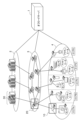
- FIG. 1 is a diagram showing an environment adaptive software system including an offload server 1 according to this embodiment.
- the environmentally adaptive software system according to this embodiment is characterized by including an offload server 1 in addition to the configuration of conventional environmentally adaptive software.
- the offload server 1 is an offload server that offloads specific processing of an application to an accelerator.
- the offload server 1 is also communicatively connected to each device located in three layers, namely, a cloud layer 2, a network layer 3, and a device layer 4.
- a data center 30 is disposed in the cloud layer 2
- a network edge 20 is disposed in the network layer 3
- a gateway 10 is disposed in the device layer 4.
- the environment-adaptive software system including the offload server 1 achieves efficiency by appropriately allocating functions and offloading processing in each of the device layer, network layer, and cloud layer. Mainly, efficiency is achieved by allocating functions to appropriate locations in the three layers for processing, and by offloading functional processing such as image analysis to heterogeneous hardware such as GPUs and FPGAs.
- FIG. 2 is a functional block diagram showing an example of the configuration of the offload server 1 according to an embodiment of the present invention.
- the offload server 1 is a device that executes environment-adaptive software processing. As one form of this environment-adaptive software, the offload server 1 automatically offloads specific processing of an application to an accelerator ( ⁇ automatic offload>). In addition, the offload server 1 can be connected to an emulator.
- the offload server 1 includes a control unit 11, an input/output unit 12, a memory unit 13, and a verification machine 14 (accelerator verification device).
- the input/output unit 12 is composed of a communication interface for sending and receiving information between each device, etc., and an input/output interface for sending and receiving information between input devices such as a touch panel or keyboard, and output devices such as a monitor.
- the storage unit 13 is configured with a hard disk, a flash memory, a RAM (Random Access Memory), or the like.
- the memory unit 13 stores a code pattern DB 131, an equipment resource DB 132, and a test case DB (Test case database) 133, and also temporarily stores programs (offload programs) for executing each function of the control unit 11 and information necessary for the processing of the control unit 11 (for example, an intermediate language file (Intermediate file) 134).
- the test case DB 133 stores performance test items.
- the test case DB 133 stores information for performing tests to measure the performance of an application to be accelerated.
- the test items are sample images and the test items for executing the images.
- the verification machine 14 includes a CPU (Central Processing Unit), a GPU, and an FPGA (accelerator) as a verification environment for the environment adaptive software.
- the offload server 1 is configured to include the verification machine 14, but the verification machine 14 may be located outside the offload server 1.
- the control unit 11 is an automatic offloading function that controls the entire offload server 1.
- the control unit 11 is realized, for example, by a CPU (not shown) that expands a program (offload program) stored in the memory unit 13 into RAM and executes it.
- the control unit 11 includes an application code specification unit (Specify application code) 111, an application code analysis unit (Analyze application code) 112, a PLD processing specification unit 113, an arithmetic strength calculation unit 114, a PLD processing pattern creation unit 115, a performance measurement unit 116, an executable file creation unit 117, a production environment deployment unit (Deploy final binary files to production environment) 118, a performance measurement test extraction execution unit (Extract performance test cases and run automatically) 119, a request processing load analysis unit 120 (processing load analysis unit), a representative data selection unit 121, an improvement degree calculation unit 122, a reconfiguration proposal unit 123, and a user provision unit (Provide price and performance to a user to judge) 124.
- the application code designation unit 111 designates the input application code. Specifically, the application code designation unit 111 identifies the processing function (image analysis, etc.) of the service provided to the user.
- the application code analysis unit 112 analyzes the source code of the processing function and understands the structure of loop statements, FFT library calls, and the like.
- the PLD processing specification unit 113 identifies loop statements (repetitive statements) in the application, and for each identified loop statement, creates and compiles a plurality of offload processing patterns specified in OpenCL for pipeline processing and parallel processing in the PLD.
- the PLD processing specification unit 113 includes an offloadable area extraction unit (Extract offloadable area) 113a and an intermediate language file output unit (Output intermediate file) 113b.
- the offload range extraction unit 113a identifies processes that can be offloaded to the FPGA, such as loop statements and FFTs, and extracts the intermediate language corresponding to the offloaded process.
- the intermediate language file output unit 113b outputs the extracted intermediate language file 134.
- Intermediate language extraction is not a one-time process, but is repeated to try and optimize execution in order to search for an appropriate offload area.
- the arithmetic intensity calculation unit 114 calculates the arithmetic intensity of a loop statement of an application using an arithmetic intensity analysis tool such as the ROSE Framework (registered trademark).
- the arithmetic intensity is the number of floating point numbers (FN) executed during program execution divided by the number of bytes accessed to the main memory (FN operations/memory access).
- Arithmetic strength is an index that increases with the number of calculations and decreases with the number of accesses, and a process with high arithmetic strength is a heavy process for a processor. Therefore, an arithmetic strength analysis tool is used to analyze the arithmetic strength of a loop statement.
- the PLD processing pattern creation unit 115 narrows down the offload candidates to loop statements with high arithmetic strength.
- the PLD processing pattern creation unit 115 Based on the arithmetic strength calculated by the arithmetic strength calculation unit 114, the PLD processing pattern creation unit 115 narrows down loop statements whose arithmetic strength is higher than a predetermined threshold (hereinafter, appropriately referred to as high arithmetic strength) as offload candidates, and creates a PLD processing pattern. In addition, as a basic operation, the PLD processing pattern creation unit 115 creates a PLD processing pattern that excludes loop statements (repetitive statements) that cause a compilation error from being offloaded, and specifies whether or not to perform PLD processing for repetitive statements that do not cause a compilation error.
- a predetermined threshold hereinafter, appropriately referred to as high arithmetic strength
- Loop count measurement function As the loop count measurement function, the PLD processing pattern creation unit 115 uses a profiling tool to measure the number of loops in an application and narrows down the loop statements that have high arithmetic strength and a loop count greater than a predetermined number (hereinafter, appropriately referred to as a high loop count). To grasp the loop count, GNU Coverage's gcov or the like is used. Known profiling tools include "GNU Profiler (gprof)" and "GNU Coverage (gcov)". Either may be used since both can investigate the number of times each loop is executed.
- a profiling tool is used to measure the number of loops in order to detect loops that have a large number of loops and a high load.
- the level of arithmetic strength indicates whether a process is suitable for offloading to an FPGA, and the number of loops x arithmetic strength indicates whether the load associated with offloading to an FPGA is high.
- the PLD processing pattern creation unit 115 creates (OpenCL) OpenCL for offloading each of the narrowed-down loop statements to the FPGA as the OpenCL creation function. That is, the PLD processing pattern creation unit 115 compiles OpenCL for offloading the narrowed-down loop statements.
- the PLD processing pattern creation unit 115 also creates a list of loop statements that have been measured and have higher performance than the CPU, and combines the loop statements in the list to create OpenCL for offloading.
- the PLD processing pattern creation unit 115 converts the loop statements into a high-level language such as OpenCL.
- the CPU processing program is divided into a kernel (FPGA) and a host (CPU) according to the grammar of the high-level language such as OpenCL.
- FPGA kernel
- CPU host
- OpenCL the high-level language
- the grammar of OpenCL For example, when one of ten for statements is to be processed by the FPGA, that one is extracted as a kernel program and described according to the grammar of OpenCL. An example of the grammar of OpenCL will be described later.
- techniques for further increasing speed can be incorporated.
- techniques for increasing speed using FPGAs include local memory cache, stream processing, multiple instantiation, loop unrolling, merging nested loop statements, memory interleaving, etc. These are often used as techniques for increasing speed, although they may not be absolutely effective for some loop statements.
- a kernel created according to the OpenCL C language syntax is executed on a device (e.g., FPGA) by a program created on the host (e.g., CPU) side using the OpenCL C language runtime API.
- the part where the kernel function hello() is called from the host side is to call clEnqueueTask(), which is one of the OpenCL runtime APIs.
- the basic flow of OpenCL initialization, execution, and termination described in the host code consists of the following steps 1 to 13. Of these steps 1 to 13, steps 1 to 10 are the procedure (preparation) until the kernel function hello() is called from the host side, and step 11 is the execution of the kernel.
- Platform Identification The platform on which OpenCL runs is identified using the function clGetPlatformIDs() that provides platform identification functionality defined in the OpenCL runtime API.
- Device Identification A device such as a GPU to be used on the platform is identified using a function clGetDeviceIDs() that provides a device identification function defined in the OpenCL runtime API.
- Context Creation An OpenCL context that serves as an execution environment for running OpenCL is created using the function clCreateContext() that provides a context creation function defined in the OpenCL runtime API.
- a command queue is created in preparation for controlling a device using the clCreateCommandQueue() function, which provides the command queue creation functionality defined in the OpenCL runtime API.
- the host issues commands to the device (such as issuing kernel execution commands and memory copy commands between the host and device) through the command queue.
- Creating a memory object A memory object that allows the host to reference the memory object is created using the clCreateBuffer() function, which provides the functionality for allocating memory on a device defined in the OpenCL runtime API.
- the execution of the kernel executed on the device is controlled by the host program. For this reason, the host program must first load the kernel program.
- the kernel program includes binary data created by the OpenCL compiler and source code written in the OpenCL C language. This kernel file is loaded (description omitted). Note that the OpenCL runtime API is not used when loading the kernel file.
- Creating a Program Object In OpenCL, a kernel program is recognized as a program project. This procedure is called creating a program object. Create a program object that allows the host to reference the memory object by using the function clCreateProgramWithSource(), which provides the program object creation function defined in the OpenCL runtime API. When creating a program object from a compiled binary sequence of a kernel program, use clCreateProgramWithBinary().
- a kernel object is created using the function clCreateKernel(), which provides the kernel object creation function defined in the OpenCL runtime API. Since one kernel object corresponds to one kernel function, the name of the kernel function (hello) is specified when creating the kernel object. Also, if multiple kernel functions are written as one program object, one kernel object corresponds one-to-one to one kernel function, so clCreateKernel() is called multiple times.
- Kernel arguments are set using the function clSetKernel(), which provides the functionality for providing arguments to the kernel defined in the OpenCL runtime API (passing values to arguments held by the kernel function). After the above steps 1 to 10 are completed, the process moves to step 11, where the host executes the kernel on the device.
- Kernel Execution Kernel execution (submission to the command queue) is an action on the device, so it is a queuing function for the command queue.
- a command to execute the kernel hello on the device is queued using a function clEnqueueTask() that provides a kernel execution function defined in the OpenCL runtime API. After the command to execute the kernel hello is queued, it will be executed on an executable computing unit on the device.
- Reading from a memory object Data is copied from the device memory area to the host memory area using the function clEnqueueReadBuffer(), which provides the function of copying data from device memory to host memory defined in the OpenCL runtime API. Data is also copied from the host memory area to the device memory area using the function clEnqueueWrightBuffer(), which provides the function of copying data from the host to host memory. Note that these functions act on the device, so the copy command is queued in the command queue once before data copying begins.
- the PLD processing pattern creation unit 115 precompiles the created OpenCL and calculates the amount of resources to be used ("first resource amount calculation").
- the PLD processing pattern creation unit 115 calculates resource efficiency based on the calculated arithmetic strength and resource amount, and selects c loop statements whose resource efficiency is higher than a predetermined value from each loop statement based on the calculated resource efficiency.
- the PLD processing pattern creation unit 115 calculates the amount of resources to be used by precompiling the combined offload OpenCL ("second resource amount calculation").
- the amount of resources may be calculated by adding up the amount of resources used in precompiling before the first measurement without precompiling.
- the performance measurement unit 116 compiles the created application of the PLD processing pattern, places it on the verification machine 14, and executes the processing for performance measurement when offloaded to the PLD.
- the performance measurement unit 116 includes a binary file deployment unit 116a.
- the binary file deployment unit 116a deploys an executable file derived from an intermediate language on the verification machine 14 including an FPGA.
- the performance measurement unit 116 executes the placed binary file, measures the performance when offloaded, and returns the performance measurement results to the offload range extraction unit 113a.
- the offload range extraction unit 113a extracts another PLD processing pattern, and the intermediate language file output unit 113b attempts to measure performance based on the extracted intermediate language (see symbol aa in Figure 3 below).
- the PLD processing pattern creation unit 115 narrows down loop statements with high resource efficiency, and compiles OpenCL that offloads the loop statements narrowed down by the executable file creation unit 117.
- the performance measurement unit 116 measures the performance of the compiled program ("first performance measurement").
- the PLD processing pattern creation unit 115 creates a list of loop statements that have been measured and have higher performance than the CPU.
- the PLD processing pattern creation unit 115 creates an OpenCL for offloading by combining the loop statements in the list.
- the PLD processing pattern creation unit 115 precompiles the combined offload OpenCL and calculates the amount of resources to be used. Note that the sum of the resource amounts in pre-compilation before the first measurement may be used without pre-compilation.
- the executable file creation unit 117 compiles the combined offload OpenCL, and the performance measurement unit 116 measures the performance of the compiled program ("second performance measurement").
- the executable file creation unit 117 selects a PLD processing pattern with the highest processing performance from among a plurality of PLD processing patterns based on the performance measurement results repeated a predetermined number of times, and compiles the PLD processing pattern with the highest processing performance to create an executable file.
- the production environment deployment unit 118 deploys the created executable file in the production environment for the user ("Deployment of final binary file in production environment").
- the production environment deployment unit 118 determines a pattern that specifies the final offload area, and deploys it to the production environment for the user.
- the performance measurement test extraction execution unit 119 After arranging the executable file, the performance measurement test extraction execution unit 119 extracts performance test items from the test case DB 133 and executes the performance tests. After arranging the executable file, the performance measurement test extraction execution unit 119 extracts performance test items from the test case DB 133 and automatically executes the extracted performance tests in order to show the performance to the user.
- the request processing load analysis unit 120 analyzes the request processing load of representative commercial data (data that is actually used by users).
- the request processing load analysis unit 120 calculates the actual processing time and the total number of uses from the usage history of each application for a specified period.
- the request processing load analysis unit 120 acquires request data for a certain period of time from the top-loaded applications, sorts the data sizes into fixed size groups, and creates a frequency distribution.
- the representative data selection unit 121 identifies the application with the highest processing load analyzed by the request processing load analysis unit 120, and selects representative data from the request data when the application is used. Specifically, the representative data selection unit 121 selects one piece of data from the actual request data that corresponds to the most frequent value Mode of the data size frequency distribution analyzed by the request processing load analysis unit 120, and selects it as the representative data.
- the improvement degree calculation unit 122 determines a new offload pattern (a new offload pattern found in the verification environment) based on the representative data selected by the representative data selection unit 121 by executing the application code analysis unit 112, the PLD processing specification unit 113, the arithmetic strength calculation unit 114, the PLD processing pattern creation unit 115, the performance measurement unit 116, and the executable file creation unit 117, and calculates the performance improvement effect by comparing the processing time and usage frequency of the determined new offload pattern with the processing time and usage frequency of the current offload pattern.
- the improvement calculation unit 122 measures the processing time of the current offload pattern and multiple new offload patterns, and calculates the performance improvement effect based on the commercial usage frequency according to (actual processing reduction time in the verification environment) x (commercial environment usage frequency).
- the reconfiguration proposing unit 123 proposes PLD reconfiguration when the performance improvement effect is equal to or greater than a predetermined threshold.
- the user providing unit 124 presents information such as price and performance based on the performance test results to the user ("Providing information such as price and performance to the user").
- the test case DB 133 stores data for automatically conducting tests to measure the performance of applications.
- the user providing unit 124 presents to the user the results of executing the test data in the test case DB 133 and the price of the entire system determined from the unit prices of the resources used in the system (virtual machines, FPGA instances, GPU instances, etc.). The user decides whether to start charging for the service based on the presented information such as price and performance.
- the offload server 1 configured as above will now be described.
- the offload server 1 is characterized in that it executes reconfiguration after the start of operation of the FPGA logic.
- the ⁇ automatic offload processing> executed by the offload server 1 as a form of environment adaptive software is the same before the start of operation and in the reconfiguration after the start of operation. That is, the automatic offload processing of the offload server 1 shown in FIG. 3 is the same before the start of operation and in the reconfiguration after the start of operation, but the difference is that the data handled before the start of operation is assumed use data, whereas the data handled in the reconfiguration after the start of operation is data actually used commercially (commercial representative data).
- the offload server 1 of this embodiment is an example in which an elemental technology of environment adaptive software is applied to FPGA automatic offloading of user application logic.
- Fig. 3 is a diagram showing the automatic offload processing of the offload server 1.
- the ⁇ automatic offload processing> in Fig. 3 is the same before the start of operation and in the reconfiguration after the start of operation.
- the offload server 1 is applied to the elemental technology of the environment adaptive software.
- the offload server 1 has a control unit (automatic offload function unit) 11 that executes the environment adaptive software processing, a code pattern DB 131, a facility resource DB 132, a test case DB 133, an intermediate language file 134, and a verification machine 14.
- the offload server 1 obtains the application code 130 used by the user.
- OpenIoT resources 15 which are a commercial environment, such as various devices 151, devices with CPU-GPU 152, devices with CPU-FPGA 153, and devices with CPU 154.
- the offload server 1 automatically offloads functional processing to the accelerators of the devices with CPU-GPU 152 and devices with CPU-FPGA 153.
- the offload server 1 executes environment-adaptive software processing by linking platform functions consisting of a code pattern DB 131, equipment resource DB 132, and test case DB 133 with the environment-adaptive functions of the commercial environment and verification environment provided by the business operator.
- Step S11 Specify application code>
- the application code designation unit 111 identifies a processing function (image analysis, etc.) of a service provided to a user. Specifically, the application code designation unit 111 designates an input application code.
- Step S12 Analyze application code>
- the application code analysis unit 112 analyzes the source code of the processing function and grasps the structures of loop statements, FFT library calls, and the like.
- Step S21 Extract offloadable area>
- the PLD processing specification unit 113 specifies loop statements (repetitive statements) of the application, specifies parallel processing or pipeline processing in the FPGA for each repetitive statement, and compiles it with a high-level synthesis tool.
- the offload range extraction unit 113a specifies processing that can be offloaded to the FPGA, such as loop statements, and extracts OpenCL as an intermediate language corresponding to the offload processing.
- Step S22 Output intermediate file: Output of intermediate language file>
- the intermediate language file output unit 113b (see FIG. 2) outputs the intermediate language file 134.
- the intermediate language extraction is not a one-time process, but is repeated to try and optimize the execution for an appropriate offload area search.
- Step S23 Compile error: PLD processing pattern creation>
- the PLD processing pattern creation unit 115 creates a PLD processing pattern that excludes loop statements that cause a compilation error from being offloaded, and specifies whether or not to perform FPGA processing for repetitive statements that do not cause a compilation error.
- Step S31 Deploy binary files: Placement of executable files>
- the binary file placement unit 116a (see FIG. 2) deploys an executable file derived from the intermediate language to the FPGA-equipped verification machine 14.
- the binary file placement unit 116a starts the placed file, executes assumed test cases, and measures the performance when offloaded.
- Step S32 Measure performances: Measure performance for appropriate pattern search>
- the performance measurement unit 116 executes the arranged file and measures the performance when offloaded. In order to determine the area to be offloaded more appropriately, the performance measurement result is returned to the offload range extraction unit 113a, which extracts another pattern.
- the intermediate language file output unit 113b then attempts performance measurement based on the extracted intermediate language (see symbol aa in FIG. 3).
- the performance measurement unit 116 repeats the performance measurement in the verification environment and finally determines the code pattern to be deployed.
- the control unit 11 repeatedly executes steps S12 to S23.
- the automatic offload function of the control unit 11 can be summarized as follows. That is, the PLD processing specification unit 113 identifies the loop statements (repeated statements) of the application, and for each repeated statement, specifies parallel processing or pipeline processing in the FPGA using OpenCL, and compiles it using a high-level synthesis tool.
- the PLD processing pattern creation unit 115 creates a PLD processing pattern that excludes loop statements that generate compilation errors from offloading targets, and specifies whether or not to perform PLD processing for loop statements that do not generate compilation errors.
- the binary file placement unit 116a then compiles the application of the corresponding PLD processing pattern, places it on the verification machine 14, and the performance measurement unit 116 executes the performance measurement processing on the verification machine 14.
- the execution file creation unit 117 selects a pattern with the highest processing performance from a plurality of PLD processing patterns based on the performance measurement results repeated a predetermined number of times, and compiles the selected pattern to create an execution file.
- Step S41 Determining resource size> The control unit 11 determines the resource size (see symbol bb in FIG. 3).
- Step S51 Selection of an appropriate placement location>
- the control unit 11 refers to the facility resource DB 132 and selects an appropriate location for placement.
- Step S61 Deploy final binary files to production environment>
- the production environment deployment unit 118 determines a pattern that specifies the final offload area, and deploys it to the production environment for the user.
- Step S62 Extract performance test cases and run automatically: Extract test cases and check normality>
- the performance measurement test extraction execution unit 119 extracts performance test items from the test case DB 133 and automatically executes the extracted performance tests in order to show the performance to the user.
- Step S63 Provide price and performance to a user to judge: Present price and performance to a user to judge whether to start using the service>
- the user providing unit 124 provides the user with information on price, performance, etc., based on the performance test results. The user determines whether to start using the service for which a fee is charged, based on the provided information on price, performance, etc.
- steps S11 to S63 are assumed to be performed in the background while the user is using the service, for example, during the first day of trial use.
- the processing performed in the background may only target GPU/FPGA offloading.
- control unit 11 of the offload server 1 extracts the area to be offloaded from the source code of the application used by the user and outputs an intermediate language to offload functional processing (steps S11 to S23).
- the control unit 11 places and executes the executable file derived from the intermediate language on the verification machine 14, and verifies the offloading effect (steps S31 to S32). After repeating the verification and determining an appropriate offload area, the control unit 11 deploys the executable file in the production environment that will actually be provided to the user, and provides it as a service (steps S41 to S63).
- the code analysis described above uses a syntax analysis tool such as Clang to analyze application code. Since code analysis requires analysis that assumes the device to be offloaded, it is difficult to generalize. However, it is possible to grasp the code structure, such as loop statements and variable reference relationships, and to grasp that a functional block performs FFT processing, or that a library that performs FFT processing is being called. It is difficult for the offload server to automatically determine the functional block. This can also be grasped by using a similar code detection tool such as Deckard to determine the similarity.
- Clang is a tool for C/C++, but it is necessary to select a tool that matches the language to be analyzed.
- offloading application processing consideration must be given to the offload destination for each GPU, FPGA, IoT GW, etc.
- Steps S11 and S12 in FIG. 3 Code analysis Steps S21 to S23 in FIG. 3: Extraction of offloadable parts Steps S31 to S32 in FIG. 3: Search for suitable offload parts Step S41 in FIG. 3: Resource amount adjustment Step S51 in FIG. 3: Placement location adjustment Steps S61 to S63 in FIG. 3: Executable file placement and operation verification
- steps S11 to S63 are required before the application can be put into operation, and involve code conversion, resource adjustment, placement location adjustment, and verification.
- the offload server 1 executes reconfiguration of the FPGA logic after the operation starts.
- the usage characteristics are analyzed and necessary reconfiguration is performed.
- the reconfiguration targets are code conversion, adjustment of resource amount, and adjustment of placement location, just like before the start of operation.
- Reconfiguration may involve offloading different loop statements within the same application, or it may involve offloading a different application.
- Dynamic reconfiguration is a technology in which the circuit configuration is changed while the FPGA is running, and the downtime required for reconfiguration is on the order of milliseconds.
- static reconfiguration is a technology in which the FPGA is stopped before changing the circuit configuration, and the downtime is on the order of one second. Whether to use dynamic or static reconfiguration depends on the impact of downtime on the user, and the reconfiguration method provided by the FPGA manufacturer can be selected. However, because downtime occurs with both methods and rewriting to a different logic requires testing to confirm operation, reconfiguration should not be performed frequently, and restrictions should be set, such as only proposing it when the effect is above a threshold.
- the reconfiguration under consideration will begin with an analysis of request trends over a certain period of time (e.g., one month).
- the request trends will be analyzed to determine whether there are any requests with a higher or equal processing load than the currently offloaded applications.
- an optimization trial of FPGA offloading will be performed in a verification environment ( Figure 3) using data that is actually used commercially (data actually used by users) rather than expected usage data.
- Whether the new offloading pattern found through verification is a sufficient improvement over the current offloading pattern is determined by whether the calculation results of processing time and usage frequency exceed or fall below a threshold. If the calculation results of processing time and usage frequency exceed the threshold, a reconfiguration is proposed to the user. After the user agrees, the commercial environment is reconfigured, but the reconfiguration is done while minimizing the impact on the user as much as possible. Furthermore, if the calculation results of processing time and usage frequency are below the threshold, no reconfiguration is proposed to the user.
- Step S71 the request processing load analysis unit 120 analyzes the request processing load of data actually used by a user. Note that a detailed flow of the commercial request data history analysis process will be described later with reference to FIG.
- step S72 the representative data selection unit 121 extracts an offload pattern for accelerating the test cases of the commercial representative data for the multiple high-load applications through the verification environment measurement. Specifically, the representative data selection unit 121 selects one piece of actual request data corresponding to the most frequent value Mode of the data size frequency distribution analyzed by the request processing load analysis unit 120 as the representative data. In the above steps S71 and S72, a high-load application is selected.
- step S73 the improvement calculation unit 122 determines a new offload pattern (a new offload pattern found in the verification environment) based on the representative data selected by the representative data selection unit 121 by executing the application code analysis unit 112, the PLD processing specification unit 113, the arithmetic strength calculation unit 114, the PLD processing pattern creation unit 115, the performance measurement unit 116, and the executable file creation unit 117, and calculates the performance improvement effect by comparing the processing time and usage frequency of the determined new offload pattern with the processing time and usage frequency of the current offload pattern.
- the improvement calculation unit 122 measures the processing time of the current offload pattern and the multiple extracted new offload patterns, and determines the performance improvement effect based on the commercial usage frequency. Specifically, the improvement calculation unit 122 calculates (actual processing time reduced in the verification environment) x (frequency of use of the commercial environment) ... formula (1) for the current offload pattern in a test case with commercial representative data. Then, the improvement calculation unit 122 calculates (actual processing time reduced in the verification environment) x (frequency of use of the commercial environment) ... formula (2) for the multiple new offload patterns. Note that the detailed flow of the commercial representative data extraction process will be described later in Figure 6.
- step S73 for applications that have been offloaded to the FPGA, the improvement coefficient is multiplied to calculate what would happen if the application was not offloaded, and the comparison is made after correcting for CPU processing only. Also, when selecting representative data, the most frequent data size mode is used, since the average data size may differ significantly from the data actually used.
- the reconfiguration proposal unit 123 determines whether to propose a reconfiguration based on whether the performance improvement effect of the new offload pattern is equal to or greater than a predetermined threshold value of the current offload pattern. Specifically, the reconfiguration proposal unit 123 obtains the calculation result of formula (2)/the calculation result of formula (1) for multiple offload patterns. The reconfiguration proposal unit 123 then checks whether the calculation result of formula (2)/the calculation result of formula (1) is equal to or greater than a predetermined threshold value, and proposes a reconfiguration if the calculation result of formula (2)/the calculation result of formula (1) is equal to or greater than the predetermined threshold value, and does nothing if it is less than the predetermined threshold value (does not propose a reconfiguration).
- step S75 the reconfiguration suggestion unit 123 suggests to the contracted user that they perform FPGA reconfiguration, and receives an OK/NG response from the contracted user regarding the execution of FPGA reconfiguration.
- step S76 the control unit 11 performs the static reconfiguration by starting another OpenCL in the commercial environment, and ends the processing of this flow. Specifically, the control unit 11 first compiles a new offload pattern. Next, the control unit 11 stops the operation of the current offload pattern and starts the operation of the new offload pattern.
- FIG. 5 is a detailed flowchart of the commercial request data history analysis process, which is a subroutine of step S71 in FIG.
- the request processing load analysis unit 120 calculates the actual processing time and the total number of uses from the usage history of each application over a certain period (long period; for example, one month). However, for applications that have been offloaded to FPGA, the processing time that would have been taken if the application had not been offloaded is provisionally calculated. From the test history of the assumed usage data before the start of operation, an improvement coefficient is calculated by dividing the actual processing time when only CPU processing is performed by the actual processing time and the actual processing time when offloaded to FPGA. The request processing load analysis unit 120 determines the sum of the values obtained by multiplying the actual processing time by the improvement coefficient as the total processing time to be used for comparison.
- step S82 the request processing load analysis unit 120 compares the total actual processing time for all applications.
- step S83 the request processing load analysis unit 120 sorts the requests in order of total actual processing time, and identifies the applications with the highest processing time loads.
- step S84 the request processing load analysis unit 120 acquires request data for a certain period (short period: 12 hours, etc.) of the top-loaded applications, sorts the data sizes into certain sizes, creates a frequency distribution, and returns to step S71 in FIG. 4.
- FIG. 6 is a detailed flow chart of the commercial representative data extraction process, which is a subroutine of step S73 in FIG.
- the improvement calculation unit 122 selects a predetermined number (four in this example) of "for" statements with high arithmetic strength from among the high-load applications.
- step S92 the improvement calculation unit 122 creates 4OpenCL that offloads four for statements, precompiles it, calculates the resource usage rate, and selects three for statements with high arithmetic strength/resource usage rate. As a result, 3OpenCL that offloads three for statements is selected.
- step S93 the improvement calculation unit 122 measures the performance of three OpenCLs using representative data. For example, the improvement calculation unit 122 creates an OpenCL that combines the top two performance-ranked for statements and measures the performance in the same way.
- step S94 the improvement calculation unit 122 determines the fastest off-load pattern among the four measurements as the solution and returns to step S72 in FIG. 4.
- the target application is a C/C++ language application
- the FPGA is an Intel PAC D5005 (Intel is a registered trademark) (Intel Stratix 10 GX FPGA).
- the compiling machine is a DELL EMC PowerEdge R740 (DELL is a registered trademark) (CPU: Intel Xeon Bronze 3206R x 2, RAM: 32GB RDIMM x 4).
- FPGA processing uses Intel Acceleration Stack Version 2.0 ("Intel” is a registered trademark) (Intel FPGA SDK for OpenCL, Intel Quartus Prime).
- the Intel Acceleration Stack enables high-level synthesis (HLS: High Level Synthesis) that interprets not only standard OpenCL but also Intel-specific ⁇ #pragmas.
- HLS High Level Synthesis
- the Intel Acceleration Stack also interprets OpenCL code that describes the kernel program to be processed by the FPGA and the host program to be processed by the CPU.
- the Intel Acceleration Stack outputs information such as resource amounts and performs FPGA wiring work, enabling it to operate on the FPGA.
- the LLVM/Clang 6.0 syntax analysis library (libClang (registered trademark) python binding) is used for C/C++ language syntax analysis.
- arithmetic strength and loop count are used to narrow down for statements.
- the ROSE compiler framework 0.9 is used to analyze arithmetic strength
- the profiler gcov is used to analyze loop counts.
- request data for a certain period is analyzed to determine the application with the highest load, and actual request data for the certain period (short period) of the application is obtained.
- the number of top load applications and the fixed period can be set by the operator, allowing for some flexibility.
- the above long period is assumed to be a long span of one month or more.
- the above short period is assumed to be a short span of 12 hours, for example.
- the actual processing time of the application and the number of times it is used are totaled, and this is obtained using the Linux (registered trademark) time command.
- the time command logs the actual elapsed time of the application, so the desired value can be calculated from the number of times logged and the total time.
- step S72 in FIG. 4 real request data for a certain period (short period) of high-load applications is sorted by a certain size to create a frequency distribution.
- the number of bins in the frequency distribution is determined by Sturges' rule.
- Sturges' rule states that when the number of times an application is used is n (n is any natural number), it is appropriate to set the number of bins to 1 + log 2 n. To use Sturges' rule, it is necessary to determine the number of bins, select the most frequent bin, and then select one representative data from the most frequent bin. In addition, when selecting representative data, data whose data size is closest to the median value of the bin is selected as the representative data.
- FPGA offloading is performed on the top-loaded application using the selected representative data in the same process as before operation started.
- the difference from before operation started is that the test cases used to measure performance are commercial representative data, rather than expected usage data.
- step S73 in FIG. 4 it is necessary to look at the improvement effect when the commercial environment is reconfigured to the new offload pattern. Since the reconfiguration has not yet been proposed by the user, verification must be performed on the verification environment server, but the improvement calculation unit 122 measures the improvement for one processing session using representative commercial data, and calculates the overall improvement degree using the frequency of commercial use. The improvement calculation unit 122 then compares the degree of effect when the commercial environment is reconfigured.
- the reconfiguration proposal unit 123 does not propose reconfiguration to the user. Since frequent reconfiguration proposals would be inconvenient for the user, the effect improvement threshold is set to a value sufficiently larger than 1x to suppress frequent reconfiguration proposals and to leave cases of truly effective reconfiguration.
- the reconfiguration threshold is a variably settable implementation, and is set to, for example, 1.5.
- the reconfiguration proposal unit 123 proposes reconfiguration to the user by adding information on price change or improvement effect.
- the information on price change or improvement effect is information on the price that will change as a result of reconfiguration, or information on how many times the improvement effect was in the verification environment even if there was no price change. This allows the contracted user to decide whether or not reconfiguration is advisable.
- the control unit 11 performs the reconfiguration using the static reconfiguration function of OpenCL.
- the static reconfiguration function is implemented in such a way that a downtime of about 1 second occurs. If it is desired to reduce the downtime to the order of ms, the reconfiguration may be performed using a dynamic reconfiguration function such as the dynamic partial reconfiguration function of Intel FPGA (registered trademark).
- the automatic offload operation (after operation has started) has been described above.
- FIG. 7 is a flowchart illustrating an outline of the operation of the offload server 1.
- the application code analysis unit 112 analyzes the source code of the application to be offloaded.
- the application code analysis unit 112 analyzes information on loop statements and variables according to the language of the source code.
- step S102 the PLD processing specification unit 113 identifies the loop statements and reference relationships of the application.
- the PLD processing pattern creation unit 115 narrows down candidates for whether or not to attempt FPGA offloading for the identified loop statements.
- Arithmetic strength is one indicator of whether or not offloading is effective for a loop statement.
- the arithmetic strength calculation unit 114 calculates the arithmetic strength of the loop statement of the application using an arithmetic strength analysis tool.
- the arithmetic strength is an index that increases with the number of calculations and decreases with the number of accesses. A process with high arithmetic strength is a heavy process for the processor.
- an arithmetic strength analysis tool is used to analyze the arithmetic strength of loop statements, and loop statements with high density are narrowed down to offloading candidates.
- the ROSE framework is used for the arithmetic strength analysis. Loops with a large number of loop counts also become heavy processes. The loop count is analyzed with a profiler, and loop statements with a large number of loop counts are also narrowed down to offloading candidates. gcov is used for loop count analysis.
- the PLD processing pattern creation unit 115 converts the target loop statement into a high-level language such as OpenCL, and first calculates the resource amount.
- the resource efficiency is set to arithmetic strength/resource amount or arithmetic strength x loop count/resource amount. Then, loop statements with high resource efficiency are further narrowed down as offload candidates.
- the CPU processing program is divided into the kernel (FPGA) and the host (CPU) according to the OpenCL grammar.
- step S104 the PLD processing pattern creation unit 115 measures the number of loops in the loop statements of the application using a profiling tool such as gcov or gprof.
- step S105 the PLD processing pattern creation unit 115 narrows down the loop statements to those with high arithmetic strength and a high number of loops.
- step S106 the PLD processing pattern creation unit 115 creates OpenCL for offloading each of the narrowed down loop statements to the FPGA.
- step S107 the PLD processing pattern creation unit 115 precompiles the created OpenCL and calculates the amount of resources to be used ("first resource amount calculation").
- step S108 the PLD processing pattern creation unit 115 narrows down the loop statements with high resource efficiency.
- step S109 the executable file creation unit 117 compiles OpenCL to offload the narrowed-down loop statements.
- step S110 the performance measurement unit 116 uses the user's usage data (data actually used by the user; commercial representative data) to measure the performance of the compiled program ("first performance measurement").
- step S111 the PLD processing pattern creation unit 115 creates a list of loop statements whose performance has been measured and whose performance has been improved compared to the CPU.
- step S112 the PLD processing pattern creation unit 115 creates an OpenCL for offloading by combining loop statements of the list.
- step S113 the PLD processing pattern creation unit 115 calculates the amount of resources to be used by precompiling with OpenCL for the combined offload ("calculating the amount of resources for the second time"). Note that it is also possible to use the sum of the amount of resources used in precompiling before the first measurement without precompiling. In this way, the number of times of precompiling can be reduced.
- step S114 the executable file creation unit 117 compiles OpenCL for the combined offload.
- step S115 the performance measurement unit 116 uses the user's usage data (data actually used by the user; commercial representative data) to measure the performance of the compiled program ("second performance measurement").
- step S116 the production environment deployment unit 118 selects the pattern with the best performance from the first and second measurements and ends the processing of this flow.
- FIG. 8 is a diagram showing an image of a search performed by the PLD processing pattern generating unit 115.
- the control unit (automatic offload function unit) 11 analyzes the application code 130 (see FIG. 3) used by the user, and checks whether or not for statements can be parallelized from the code patterns 141 of the application code 130, as shown in FIG. 8.
- the symbol a in FIG. 8 when four for statements are found from the code pattern 141, one digit is assigned to each for statement, in this case four digits of 1 or 0 are assigned to the four for statements.
- 1 is assigned when FPGA processing is performed
- 0 is assigned when FPGA processing is not performed (i.e. processing is performed by the CPU).
- Steps A to F in FIG. 9 are diagrams for explaining the flow from the C code to the search for the final OpenCL solution.
- the application code analysis unit 112 (see FIG. 2) performs syntax analysis of the "C code” shown in step A of FIG. 9 (see symbol b in FIG. 9), and the PLD processing specification unit 113 (see FIG. 2) identifies the "loop statement, variable information" shown in step B of FIG. 9 (see FIG. 8).
- the arithmetic strength calculation unit 114 performs an arithmetic intensity analysis on the identified "loop statement, variable information" using an arithmetic strength analysis tool.
- the PLD processing pattern creation unit 115 narrows down the offload candidates to loop statements with high arithmetic strength. Furthermore, the PLD processing pattern creation unit 115 performs a profiling analysis using a profiling tool (see symbol c in FIG. 9) to further narrow down the loop statements with high arithmetic strength and a high number of loops. Then, the PLD processing pattern creation unit 115 creates OpenCL for offloading each of the narrowed down loop statements to the FPGA (OpenCL conversion). Furthermore, when converting to OpenCL, we will introduce speed-up techniques such as code splitting and unrolling (see below).
- the PLD processing pattern creation unit 115 compiles OpenCL to offload the narrowed-down loop statements.
- the performance measurement unit 116 measures the performance of the compiled program ("first performance measurement"). Then, the PLD processing pattern creation unit 115 creates a list of loop statements whose performance has been measured and whose performance has been improved compared to the CPU. Thereafter, similarly, the resource amount is calculated, offload OpenCL compilation is performed, and the performance of the compiled program is measured.
- the executable file creation unit 117 compiles (main compiles) OpenCL to offload the narrowed-down loop statements.
- step E of Figure 9 refers to measuring the candidate loop statements individually, and then measuring the verification patterns for those combinations.
- FPGAs that can be used include Intel PAC with Intel Arria10 GX FPGA.
- Intel Acceleration Stack Intelligent FPGA SDK for OpenCL, Quartus Prime Version
- the Intel FPGA SDK for OpenCL is a high-level synthesis tool (HLS) that interprets standard OpenCL as well as Intel-specific #pragma directives.
- HLS high-level synthesis tool
- the OpenCL code that describes the kernel to be processed by the FPGA and the host program to be processed by the CPU is interpreted, information such as resource amounts is output, and wiring work for the FPGA is performed so that it can run on the FPGA.
- the code of the C/C++ application is first analyzed to discover for statements and to understand the program structure, such as variable data used within the for statements.
- the code of the C/C++ application is first analyzed to discover for statements and to understand the program structure, such as variable data used within the for statements.
- syntax analysis LLVM/Clang syntax analysis libraries, etc. can be used.
- an arithmetic strength analysis tool is executed to obtain an index of arithmetic strength determined by the number of calculations, the number of accesses, etc.
- the ROSE framework, etc. can be used for the arithmetic strength analysis. Only the loop statements with the highest arithmetic strength are targeted.
- a profiling tool such as gcov is used to obtain the loop count of each loop. The top a loop statements based on arithmetic strength x loop count are narrowed down to candidates.
- OpenCL code is generated for each loop statement with high arithmetic strength to be offloaded to the FPGA.
- the OpenCL code is divided into the relevant loop statement as the FPGA kernel and the rest as the CPU host program.
- a fixed number b of loop statement expansion may be performed as a speed-up technique. Loop statement expansion increases the amount of resources required, but is effective in increasing speed. Therefore, the number of expansions is limited to a fixed number b so that the amount of resources does not become excessive.
- the Intel FPGA SDK for OpenCL is used to precompile a number of OpenCL codes, and the amount of resources used, such as flip flops and look up tables, is calculated.
- the amount of resources used is displayed as a percentage of the total resource amount.
- the resource efficiency may be calculated by multiplying the number of loops. For each loop statement, c statements with the highest resource efficiency are selected.
- a pattern to be measured is created with c loop statements as candidates. For example, if the first and third loops are highly resource efficient, an OpenCL pattern is created to offload loop 1 and loop 3, and then compiled and performance is measured. If speed can be improved by offloading multiple single-loop statements (for example, if both loops 1 and 3 are fast), an OpenCL pattern for that combination is created, compiled, and performance is measured (for example, a pattern to offload both loops 1 and 3).
- the amount of resources used is also included in the combination. Therefore, if the amount does not fall within the upper limit, the combination pattern will not be created.
- performance is measured on a server equipped with an FPGA in the verification environment. To measure performance, sample processing specified by the application to be accelerated is performed. For example, in the case of a Fourier transform application, performance is measured by benchmarking the conversion process on sample data. In the implementation example, finally, the fastest pattern among the multiple measurement patterns is selected as the solution.
- the offload server 1 is realized by, for example, a computer 900 having a configuration as shown in Fig. 10.
- the verification machine 14 shown in Fig. 2 is located outside the offload server 1.
- FIG. 10 is a hardware configuration diagram showing an example of a computer 900 that realizes the functions of the offload server 1.
- the computer 900 has a CPU 910 , a RAM 920 , a ROM 930 , a HDD 940 , a communication interface (I/F) 950 , an input/output interface (I/F) 960 , and a media interface (I/F) 970 .
- the CPU 910 operates based on the programs stored in the ROM 930 or the HDD 940, and controls each component.
- the ROM 930 stores a boot program executed by the CPU 910 when the computer 900 starts up, and programs that depend on the hardware of the computer 900, etc.
- the HDD 940 stores the programs executed by the CPU 910 and the data used by such programs.
- the communication interface 950 receives data from other devices via the communication network 80 and sends it to the CPU 910, and transmits data generated by the CPU 910 to other devices via the communication network 80.
- the CPU 910 controls output devices such as a display and a printer, and input devices such as a keyboard and a mouse, via the input/output interface 960.
- the CPU 910 acquires data from the input devices via the input/output interface 960.
- the CPU 910 also outputs generated data to the output devices via the input/output interface 960.
- the media interface 970 reads a program or data stored in the recording medium 980 and provides it to the CPU 910 via the RAM 920.
- the CPU 910 loads the program from the recording medium 980 onto the RAM 920 via the media interface 970 and executes the loaded program.
- the recording medium 980 is, for example, an optical recording medium such as a DVD (Digital Versatile Disc) or a PD (Phasechangerewritable Disk), a magneto-optical recording medium such as an MO (Magneto Optical disk), a tape medium, a magnetic recording medium, or a semiconductor memory.
- the CPU 910 of the computer 900 executes programs loaded onto the RAM 920 to realize the functions of each part of the offload server 1.
- the HDD 940 stores data for each part of the offload server 1.
- the CPU 910 of the computer 900 reads and executes these programs from the recording medium 980, but as another example, these programs may be obtained from another device via the communication network 80.
- the offload server 1 includes an application code analysis unit 112 that analyzes the source code of an application, a PLD processing specification unit 113 that identifies loop statements in the application, and creates and compiles a plurality of offload processing patterns that specify pipeline processing and parallel processing in the PLD by OpenCL for each identified loop statement, an arithmetic strength calculation unit 114 that calculates the arithmetic strength of the loop statement of the application, a PLD processing pattern creation unit 115 that narrows down loop statements having an arithmetic strength higher than a predetermined threshold as offload candidates based on the arithmetic strength calculated by the arithmetic strength calculation unit 114 and creates a PLD processing pattern, a performance measurement unit 116 that compiles an application of the created PLD processing pattern, places it in the accelerator verification device 14, and executes a process for measuring performance when offloaded to the PLD, an execution file creation unit 117 that selects a PLD processing pattern with the highest processing performance from
- a representative data selection unit 121 that identifies an application having a high processing load analyzed by the request processing load analysis unit 120 and selects representative data from request data when the application is used; and a new offload pattern (a new offload pattern found in the verification environment) based on the representative data selected by the representative data selection unit 121, which is executed by an application code analysis unit 112, a PLD processing designation unit 113, an arithmetic strength calculation unit 114, a PLD processing pattern creation unit 115, a performance measurement unit 116, and an executable file creation unit 117.
- the representative data selection unit 121 determines a performance improvement effect by comparing the processing time and usage frequency of the new offload pattern determined based on the representative data, and calculates a performance improvement effect by comparing the processing time and usage frequency of the new offload pattern (a new offload pattern found in the verification environment) with the processing time and usage frequency of the current offload pattern, based on the representative data selected by the representative data selection unit 121; and a reconfiguration proposal unit 123 proposes PLD reconfiguration if the performance improvement effect is equal to or greater than a predetermined threshold.
- the offload server 1 can be reconfigured to a more appropriate logic according to the usage characteristics not only before operation begins but also after operation begins, thereby making it possible to improve the efficiency of resource utilization in a PLD (e.g., an FPGA) with limited resource amounts.
- a PLD e.g., an FPGA
- the offload server 1 can reconfigure the FPGA logic in response to changes in usage characteristics after the application has started operating, if there is a possibility that the data will deviate significantly from the data actually used after operation has started, for example, if the usage pattern after operation has started differs from what was initially expected and offloading other logic to the FPGA would improve performance, the FPGA logic can be reconfigured with minimal impact on the user. Note that reconfiguration may involve changing the offloading of a different loop statement in the same application, or changing the offloading of a different application. There are many targets for reconfiguration, such as GPUs, FPGA offload logic, resource amounts, and placement locations.
- the request processing load analysis unit 120 is characterized by calculating the actual processing time and the total number of uses from the usage history of each application for a specified period.
- the offload server 1 can analyze the request processing load of data actually being used by users from the usage history of each application over a certain period of time.
- the request processing load analysis unit 120 calculates an improvement coefficient from the test history of the assumed usage data before the start of operation by dividing the actual processing time with CPU processing only by the actual processing time with PLD offloading, and determines the sum of the values obtained by multiplying the improvement coefficient by the actual processing time as the total processing time to be used for comparison.
- the offload server 1 selects the top-loaded application, it can multiply the FPGA-offloaded application by the improvement coefficient, calculate the case where the application is not offloaded, and make a comparison by correcting to CPU processing only. Since the case where the application is not offloaded is corrected by multiplying by the improvement coefficient, a more accurate calculation of actual processing time is possible.
- the request processing load analysis unit 120 acquires request data for a specified period of time from the top-loaded applications, sorts the data sizes into fixed size groups to create a frequency distribution, and the representative data selection unit 130 selects one piece of actual request data that corresponds to the most frequent value Mode of the frequency distribution, and selects it as the representative data.
- the offload server 1 selects representative data
- the average data size may differ significantly from the actual data usage, but by using the most frequent data size mode, it is possible to select more appropriate representative data.
- the improvement calculation unit 122 measures the processing time of the current offload pattern and multiple new offload patterns, and calculates the performance improvement effect based on the commercial usage frequency according to (reduced actual processing time in the verification environment) x (usage frequency in the commercial environment).
- the offload server 1 can calculate (the actual processing time reduction in the verification environment) x (the frequency of use of the commercial environment) for multiple new offload patterns, and calculate (the actual processing time reduction in the verification environment) x (the frequency of use of the commercial environment) for the current offload pattern, and by dividing the former by the latter, it is possible to obtain a more accurate performance improvement effect using the two parameters of processing time and frequency of use.
- the present invention is an offload program for causing a computer to function as the above-mentioned offload server.
- the above-mentioned configurations, functions, processing units, processing means, etc. may be realized in hardware, in part or in whole, for example by designing them as integrated circuits. Further, the above-mentioned configurations, functions, etc. may be realized by software that causes a processor to interpret and execute programs that realize the respective functions. Information on the programs, tables, files, etc. that realize the respective functions can be stored in a memory, a recording device such as a hard disk or SSD (Solid State Drive), or a recording medium such as an IC (Integrated Circuit) card, SD (Secure Digital) card, or optical disc.
- a recording device such as a hard disk or SSD (Solid State Drive)
- a recording medium such as an IC (Integrated Circuit) card, SD (Secure Digital) card, or optical disc.
- a for statement is used as an example of a repetitive statement (loop statement), but other statements besides the for statement, such as a while statement or a do-while statement, are also included. However, a for statement that specifies the continuation conditions of the loop, etc., is more suitable.
Landscapes
- Engineering & Computer Science (AREA)
- Software Systems (AREA)
- Theoretical Computer Science (AREA)
- Physics & Mathematics (AREA)
- General Engineering & Computer Science (AREA)
- General Physics & Mathematics (AREA)
- Debugging And Monitoring (AREA)
- Multi Processors (AREA)
Abstract
Un serveur de délestage (1) comprend : une unité d'analyse de charge de traitement de demande (120) qui analyse une charge de traitement de demande de données en cours d'utilisation par un utilisateur ; une unité de sélection de données représentatives (121) qui identifie une application pour laquelle la charge de traitement analysée est la plus élevée, et qui sélectionne des données représentatives parmi les données de demande pendant l'utilisation de ladite application ; une unité de calcul de degré d'amélioration (122) qui, sur la base des données représentatives sélectionnées, détermine un nouveau modèle de délestage par exécution d'une unité d'analyse de code d'application (112), d'une unité de désignation de traitement de PLD (113), d'une unité de calcul d'intensité arithmétique (114), d'une unité de création de modèle de traitement de PLD (115), d'une unité de mesure de performance (116) et d'une unité de création de fichier d'exécution (117), et qui calcule un effet d'amélioration de performance par comparaison du temps de traitement et de la fréquence d'utilisation du nouveau modèle de délestage déterminé au temps de traitement et à la fréquence d'utilisation du modèle de délestage courant ; et une unité de proposition de reconfiguration (123) qui propose une reconfiguration de PLD lorsque l'effet d'amélioration de performance est supérieur ou égal à un seuil prescrit.
Priority Applications (1)
| Application Number | Priority Date | Filing Date | Title |
|---|---|---|---|
| PCT/JP2022/038384 WO2024079886A1 (fr) | 2022-10-14 | 2022-10-14 | Serveur de délestage, procédé de commande de délestage et programme de délestage |
Applications Claiming Priority (1)
| Application Number | Priority Date | Filing Date | Title |
|---|---|---|---|
| PCT/JP2022/038384 WO2024079886A1 (fr) | 2022-10-14 | 2022-10-14 | Serveur de délestage, procédé de commande de délestage et programme de délestage |
Publications (1)
| Publication Number | Publication Date |
|---|---|
| WO2024079886A1 true WO2024079886A1 (fr) | 2024-04-18 |
Family
ID=90669262
Family Applications (1)
| Application Number | Title | Priority Date | Filing Date |
|---|---|---|---|
| PCT/JP2022/038384 WO2024079886A1 (fr) | 2022-10-14 | 2022-10-14 | Serveur de délestage, procédé de commande de délestage et programme de délestage |
Country Status (1)
| Country | Link |
|---|---|
| WO (1) | WO2024079886A1 (fr) |
Citations (1)
| Publication number | Priority date | Publication date | Assignee | Title |
|---|---|---|---|---|
| JP2020137017A (ja) * | 2019-02-22 | 2020-08-31 | 日本電信電話株式会社 | オフロードサーバのソフトウェア最適配置方法およびプログラム |
-
2022
- 2022-10-14 WO PCT/JP2022/038384 patent/WO2024079886A1/fr unknown
Patent Citations (1)
| Publication number | Priority date | Publication date | Assignee | Title |
|---|---|---|---|---|
| JP2020137017A (ja) * | 2019-02-22 | 2020-08-31 | 日本電信電話株式会社 | オフロードサーバのソフトウェア最適配置方法およびプログラム |
Non-Patent Citations (2)
| Title |
|---|
| YOJI YAMATO: "Evaluation of Automatic GPU and FPGA Offloading for Function Blocks of Applications", ICONFERENCE, ASSOCIATION FOR COMPUTING MACHINERY NEW YORK, NY, UNITED STATES, vol. 119, no. 482, 9 March 2020 (2020-03-09), pages 59 - 66, XP093158027, ISSN: 2331-8422, DOI: 10.48550/arxiv.2005.04174 * |
| YOJI YAMATO: "Proposal of Automatic FPGA Offloading for Applications Loop Statements", ICONFERENCE, ASSOCIATION FOR COMPUTING MACHINERY NEW YORK, NY, UNITED STATES, 18 April 2020 (2020-04-18), pages 111 - 123, XP093158029, ISSN: 2331-8422, DOI: 10.48550/arxiv.2004.08548 * |
Similar Documents
| Publication | Publication Date | Title |
|---|---|---|
| US11614927B2 (en) | Off-load servers software optimal placement method and program | |
| Pérez et al. | Simplifying programming and load balancing of data parallel applications on heterogeneous systems | |
| US11243816B2 (en) | Program execution on heterogeneous platform | |
| CN112106023A (zh) | 卸载服务器和卸载程序 | |
| JP7322978B2 (ja) | オフロードサーバ、オフロード制御方法およびオフロードプログラム | |
| WO2024079886A1 (fr) | Serveur de délestage, procédé de commande de délestage et programme de délestage | |
| CN112997146A (zh) | 卸载服务器和卸载程序 | |
| Yamato | Proposal and Evaluation of GPU Offloading Parts Reconfiguration During Applications Operations for Environment Adaptation | |
| JP7363931B2 (ja) | オフロードサーバ、オフロード制御方法およびオフロードプログラム | |
| Yamato | Proposal of Automatic FPGA Offloading for Applications Loop Statements | |
| JP2023180315A (ja) | 変換プログラムおよび変換処理方法 | |
| WO2022097245A1 (fr) | Serveur de délestage, procédé de commande de délestage et programme de délestage | |
| Yamato | Proposal and evaluation of adjusting resource amount for automatically offloaded applications | |
| Wang et al. | Clustered workflow execution of retargeted data analysis scripts | |
| Angelelli et al. | Towards a Multi-objective Scheduling Policy for Serverless-based Edge-Cloud Continuum | |
| US11947975B2 (en) | Offload server, offload control method, and offload program | |
| WO2023228369A1 (fr) | Serveur de délestage, procédé de commande de délestage et programme de délestage | |
| WO2023002546A1 (fr) | Serveur de délestage, procédé de commande de délestage et programme de délestage | |
| WO2023144926A1 (fr) | Serveur de délestage, procédé de commande de délestage et programme de délestage | |
| WO2022102071A1 (fr) | Serveur de délestage, procédé de commande de délestage et programme de délestage | |
| JP7473003B2 (ja) | オフロードサーバ、オフロード制御方法およびオフロードプログラム | |
| JP7363930B2 (ja) | オフロードサーバ、オフロード制御方法およびオフロードプログラム | |
| JP7184180B2 (ja) | オフロードサーバおよびオフロードプログラム | |
| Antonov et al. | Strategies of Computational Process Synthesis—A System-Level Model of HW/SW (Micro) Architectural Mechanisms | |
| US20220222177A1 (en) | Systems, apparatus, articles of manufacture, and methods for improved data transfer for heterogeneous programs |