WO2024075232A1 - 中継装置、基地局装置、及び無線通信システム - Google Patents
中継装置、基地局装置、及び無線通信システム Download PDFInfo
- Publication number
- WO2024075232A1 WO2024075232A1 PCT/JP2022/037347 JP2022037347W WO2024075232A1 WO 2024075232 A1 WO2024075232 A1 WO 2024075232A1 JP 2022037347 W JP2022037347 W JP 2022037347W WO 2024075232 A1 WO2024075232 A1 WO 2024075232A1
- Authority
- WO
- WIPO (PCT)
- Prior art keywords
- state
- base station
- relay
- rrc
- station device
- Prior art date
- Legal status (The legal status is an assumption and is not a legal conclusion. Google has not performed a legal analysis and makes no representation as to the accuracy of the status listed.)
- Ceased
Links
Images






Classifications
-
- H—ELECTRICITY
- H04—ELECTRIC COMMUNICATION TECHNIQUE
- H04W—WIRELESS COMMUNICATION NETWORKS
- H04W16/00—Network planning, e.g. coverage or traffic planning tools; Network deployment, e.g. resource partitioning or cells structures
- H04W16/24—Cell structures
- H04W16/26—Cell enhancers or enhancement, e.g. for tunnels, building shadow
Definitions
- the present invention relates to a relay device, a base station device, and a wireless communication system.
- wireless communication is achieved when a terminal device receives a signal (radio waves) transmitted from a base station device.
- a signal radio waves
- the terminal device cannot receive it.
- repeaters that amplify and transmit the radio waves received from the base station device.
- users can transmit amplified radio waves to blind zones where radio waves cannot reach because they are in the shadow of a building or object, or are located far away from the base station device, thereby reducing the areas where terminal devices cannot communicate wirelessly.
- NCR Network Controlled Repeater
- 3GPP TS 36.133 V17.6.0 3GPP TS 36.211 V17.2.0 3GPP TS 36.212 V17.1.0 3GPP TS 36.213 V17.2.0 3GPP TS 36.214 V17.0.0 3GPP TS 36.300 V17.1.0 3GPP TS 36.321 V17.1.0 3GPP TS 36.322 V17.0.0 3GPP TS 36.323 V17.1.0 3GPP TS 36.331 V17.1.0 3GPP TS 37.324 V17.0.0 3GPP TS 37.340 V17.1.0 3GPP TS 38.133 V17.6.0 3GPP TS 38.201 V17.0.0 3GPP TS 38.202 V17.2.0 3GPP TS 38.211 V17.2.0 3GPP TS 38.212 V17.2.0 3GPP TS 38.213 V17.2.0 3GPP TS 38.214 V17.2.0 3GPP TS 38.215 V17.1.0 3GPP TS 38.300 V17.1.0
- NCR is still in the planning stages, and detailed processing has yet to be determined. In particular, possible states and state transitions for NCR have not yet been determined.
- one disclosure provides a relay device, a base station device, and a wireless communication system that can achieve appropriate state transitions of the NCR.
- a relay device having a relay function for relaying wireless communication between a base station device and a terminal device, the relay function being controlled by the base station device, the relay device having a receiving unit that receives a signal including information instructing a transition of a communication state from the base station device, and a control unit that controls the communication state to transition from a second state to a first state when the signal is a first signal including a first identifier.
- One disclosure can achieve appropriate state transitions in NCR.
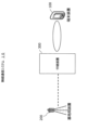
- FIG. 1 is a diagram showing an example of wireless communication in a wireless communication system 10.
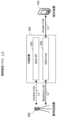
- FIG. 2 is a diagram illustrating an example of the software configuration of the relay device 300 in the wireless communication system 10.
- FIG. 3 is a diagram showing an example of the configuration of the relay device 300.
- FIG. 4 is a diagram illustrating an example of the configuration of the base station device 200.
- FIG. 5 is a diagram illustrating an example of the configuration of the terminal device 100.
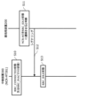
- FIG. 6 is a diagram showing an example of a sequence for transitioning to the RRC_IDLE state.
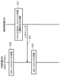
- FIG. 7 is a diagram showing an example of a sequence for transitioning to the RRC_INACTIVE state.
- FIG. 8 is a diagram showing an example of a sequence for transitioning to the RRC_CONNECTED state.
- FIG. 9 is a diagram showing an example of description of a process for transitioning to the RRC_IDLE state by an L2 signal.
- FIG. 10 is a diagram showing an example of the description of parameters included in the RRCRelease.
- FIG. 11 is a diagram showing an example of a description of the paging process for the NCR.
- FIG. 12 is a diagram showing an example of a description regarding the suspendConfig parameter.
- FIG. 13 is a diagram showing an example of the description of the operation upon receiving an RRCRelease including a suspendConfig parameter.
- FIG. 14 is a diagram showing an example of description regarding deactivation of the PCell.
- ⁇ Regarding wireless communication system 10> 1 is a diagram showing an example of the configuration of a wireless communication system 10.
- the wireless communication system 10 includes a base station device 200, a relay device 300, and a terminal device 100.
- the terminal device 100 is a communication device that wirelessly connects to the base station device 200 and transmits and receives data, and is, for example, a smartphone or a tablet terminal.
- the terminal device 100 also wirelessly connects to the relay device 300 and communicates with the base station device 200 via the relay device 300.
- the base station device 200 is a communication device that is wirelessly connected to the terminal device 100 and performs wireless communication, and is, for example, an eNodeB or gNodeB.
- the base station device 200 supports, for example, various communication generations (for example, 4G, 5G, and Beyond 5G).
- the base station device 200 may be configured as a single device, or may be configured as multiple devices such as a CU (Central Unit) and a DU (Distributed Unit).
- the relay device 300 is a communication device that receives radio waves from the base station device 200 and transmits the amplified radio waves by beamforming, for example, an NCR.
- the relay process of the relay device 300 is controlled, for example, by the base station device 200.
- the radio waves (signals) that the relay device 300 can amplify may be compatible with multiple base station devices 200, but in this embodiment, it is assumed that the relay device 300 is compatible with one base station device 200.
- ⁇ Example of Software Configuration of Relay Device 300> 2 is a diagram illustrating an example of a software configuration of the relay device 300 in the wireless communication system 10.
- the relay device 300 includes an NCR-MT (Mobile Termination) 301 and an NCR-Fwd (Forwarding) 302.
- NCR-MT301 is a control unit that wirelessly communicates with the base station device 200 via a control link L1, enabling transmission and reception of side control information and the like.
- the NR (New Radio) Uu interface is used as the control link L1.
- the side control information includes, for example, information relating to the control of the NCR-Fwd302, which is described below.
- NCR-Fwd 302 is a relay unit that amplifies and forwards signals (radio waves) between the base station device 200 and the terminal device 100 via the backhaul link L2 and the access link L3.
- NCR-Fwd 302 is controlled and determines the relay processing according to side control information received from the base station device 200. Note that forwarding includes amplifying signals received from the base station device 200 and transmitting them to the terminal device 100, and amplifying signals received from the terminal device 100 and transmitting them to the base station device 200.
- ⁇ Configuration Example of Relay Device 300> 3 is a diagram showing an example of the configuration of the relay device 300.
- the relay device 300 includes a CPU (Central Processing Unit) 310, a storage 320, a memory 330, a wireless communication circuit 350, and a wireless communication circuit 351.
- CPU Central Processing Unit
- Storage 320 is an auxiliary storage device such as a flash memory, HDD (Hard Disk Drive), or SSD (Solid State Drive) that stores programs and data.
- Storage 320 stores a relay program 321 and a state transition program 322.
- Memory 330 is an area into which programs stored in storage 320 are loaded. Memory 330 may also be used as an area in which programs store data.
- the wireless communication circuit 350 is a device that performs wireless communication with the base station device 200.
- the relay device 300 transmits and receives signals to and from the base station device 200 via the wireless communication circuit 350.
- the wireless communication circuit 351 is a device that performs wireless communication with the terminal device 100.
- the relay device 300 transmits and receives signals to and from the terminal device 100 via the wireless communication circuit 351.
- CPU 310 is a processor that loads programs stored in storage 320 into memory 330, executes the loaded programs, configures each component, and realizes each process.
- the CPU 310 executes the relay program 321 to construct a relay section and perform relay processing.
- the relay processing is a process of receiving a control signal from the base station device 200 and relaying (amplifying and transferring) the signal to the terminal device 100 in accordance with the control signal.
- the CPU 310 executes the state transition program 322 to construct a control unit and a receiving unit, and to perform state transition processing.
- the state transition processing is a process of receiving a signal instructing a state transition from the base station device 200, and controlling the state according to the instruction of the base station device 200.
- the state transition processing also includes processing of autonomous state transition.
- ⁇ Configuration example of base station device 200> 4 is a diagram illustrating an example of the configuration of the base station device 200.
- the base station device 200 includes a CPU 210, a storage 220, a memory 230, and a wireless communication circuit 250.
- Storage 220 is an auxiliary storage device such as a flash memory, HDD, or SSD that stores programs and data.
- Storage 220 stores a wireless communication control program 221 and a relay control program 222.
- Memory 230 is an area into which programs stored in storage 220 are loaded. Memory 230 may also be used as an area in which programs store data.
- the wireless communication circuit 250 is a device that performs wireless communication with the terminal device 100.
- the wireless communication circuit 250 may also perform wireless communication with the relay device 300.
- the CPU 210 is a processor that loads the programs stored in the storage 220 into the memory 230, executes the loaded programs, configures each component, and realizes each process.
- the CPU 210 executes the wireless communication control program 221 to construct a communication unit and perform wireless communication control processing.
- the wireless communication control processing is processing for performing wireless communication with the terminal device 100.
- the base station device 200 wirelessly connects to the terminal device 100 and transmits signals to a destination and receives signals.
- the wireless communication control processing also includes processing for communicating with the terminal device 100 via the relay device 300.
- the CPU 210 executes the relay control program 222 to construct a receiving section and a relay control section, and to perform relay control processing.
- the relay control processing is processing for controlling the relay processing performed by the relay device 300.
- the base station device 200 performs wireless communication between itself and the relay device 300.
- the CPU 210 executes the state control module 2221 of the relay control program 222 to construct a receiving section and a relay control section, and to perform state control processing.
- the state control processing is processing for controlling the communication state of the relay device 300 (the communication state with the NCR-MT 301).
- ⁇ Configuration example of terminal device 100> 5 is a diagram illustrating an example of the configuration of the terminal device 100.
- the terminal device 100 includes a CPU 110, a storage 120, a memory 130, and a wireless communication circuit 150.
- Storage 120 is an auxiliary storage device such as a flash memory, HDD, or SSD that stores programs and data.
- Storage 120 stores wireless communication program 121.
- Memory 130 is an area into which programs stored in storage 120 are loaded. Memory 130 may also be used as an area in which programs store data.
- the wireless communication circuit 150 is a device that performs wireless communication with the base station device 200.
- the wireless communication circuit 150 may also perform wireless communication with the relay device 300.
- the CPU 110 is a processor that loads the programs stored in the storage 120 into the memory 130, executes the loaded programs, configures each component, and realizes each process.
- the CPU 110 executes the wireless communication program 121 to construct a terminal communication unit and perform wireless communication processing.
- the wireless communication processing is processing for performing wireless communication with the base station device 200 and the relay device 300.
- the terminal device 100 realizes wireless communication by wirelessly connecting to the base station device 200 and the relay device 300 and transmitting and receiving signals (messages).
- the relay device 300 may be in the following states depending on the connection state of the RRC (Radio Resource Control) of the control link L1, for example.
- RRC_IDLE state RRC_INACTIVE state
- RRC_CONNECTED state RRC_CONNECTED state
- the RRC_IDLE state is a state in which there is no RRC connection with the base station device 200, and the relay device 300 monitors the paging channel to receive CN (Core Network) paging and receives notification information.
- the RRC_CONNECTED state is a state in which there is a wireless connection with the base station device 200, and communication including sending and receiving individual signals of the relay device 300 can be performed at all times.
- the RRC_INACTIVE state is a state in which the wireless connection with the base station device 200 is temporarily suspended, and the relay device 300 monitors the paging channel to receive CN (Core Network) paging and RAN (Radio Access Network) paging, and receives notification information.
- the relay device 300 In the RRC_INACTIVE state, the relay device 300 holds information called UE Inactive AS Context, which allows it to resume the RRC connection with the base station device 200.
- the UE Inactive AS Context includes, for example, security key information, cell configuration information, and identifier information used to transmit and receive signals individual to the relay device 300 that were used before the relay device 300 transitioned from the RRC_CONNECTED state to the RRC_INACTIVE state.
- the relay device 300 In the RRC_IDLE and RRC_INACTIVE states, the relay device 300 only needs to energize the transmission/reception circuitry at specific times, so power consumption can be reduced more than in the RRC_CONNECTED state, in which the transmission/reception circuitry needs to be energized at all times to perform continuous communication.
- the state transition in the control link L1 is asynchronous with the state (connection state) of the backhaul link L2 and the access link L3.
- the backhaul link L2 and the access link L3 are links used for communication between the base station device 200 and the terminal device 100, and are not subject to the control of the relay device 300 (NCR-MT301).
- the RRC_IDLE state may be, for example, a state in which individual wireless communication (except for obtaining paging) is not being performed, and an RRC connection is required when individual wireless communication starts.
- the RRC_CONNECTED state may be, for example, a state in which individual wireless communication (except for obtaining paging) is not being performed, and an RRC connection must be resumed when individual wireless communication starts.
- Base station device-initiated state transition The state transitions initiated by the base station device 200 will be described.
- FIG. 6 shows an example of a sequence for transitioning to the RRC_IDLE state.
- the NCR-MT 301 of the relay device 300 is in the RRC_CONNECTED state or the RRC_INACTIVE state (S10).
- the base station device 200 determines to transition the NCR-MT301 to the RRC_IDLE state (S11).
- the base station device 200 determines to transition the NCR-MT301 to the RRC_IDLE state when, for example, the NCR_Fwd302 has not been used for a predetermined time (no signals or messages are sent or received) or the relay process has not been performed for a predetermined time.
- the base station device 200 may, for example, periodically receive a report from the NCR_MT301 that includes information such as the frequency of use and communication volume of the NCR-Fwd302 as a method of acquiring whether the NCR_Fwd302 is being used.
- the base station device 200 transmits signaling to the NCR-MT 301 instructing it to transition to the RRC_IDLE state (S12).
- the signaling may include, for example, a paging reception identifier used when transitioning to the RRC_CONNECTED state.
- the signaling may also include, for example, a timer value used by the relay device 300. For example, when the timer expires, the NCR-MT 301 transitions again to the RRC_CONNECTED state (or the RRC_INACTIVE state).
- the signaling may also include cell information (including information about the base station device 200) used when transitioning to the RRC_CONNECTED state.
- L1 Layer 1
- L2 Layer 2
- An L1 signal is, for example, a DCI (Downlink Control Information).
- An L2 signal is, for example, a MAC CE (Control Element).
- the signaling may also be, for example, an RRCRelease message.
- NCR-MT301 When NCR-MT301 receives signaling (S12), it transitions to the RRC_IDLE state (S13). For example, if the signaling is L1, NCR_MT301 notifies the upper layer from the PHY (PHYsical layer), disconnects (releases) the wireless connection in RRC, and transitions to the RRC_IDLE state.
- the upper layer of the PHY is, for example, the MAC (Medium Access Control layer).
- the upper layer of the PHY is, for example, the RRC layer.
- the signaling is L2
- NCR_MT301 notifies the upper layer from the MAC (Medium Access Control layer), disconnects (releases) the wireless connection in RRC, and transitions to the RRC_IDLE state.
- the upper layer of the MAC is, for example, the RRC layer.
- NCR_MT301 disconnects (releases) the wireless connection in RRC and transitions to the RRC_IDLE state.
- FIG. 7 shows an example of a sequence for transitioning to the RRC_INACTIVE state.
- the NCR-MT 301 of the relay device 300 is in the RRC_CONNECTED state (S20).
- the base station device 200 determines to transition the NCR-MT 301 to the RRC_INACTIVE state (S21).
- the criteria for the base station device 200 are, for example, the same as the criteria for determining to transition to the RRC_IDLE state.
- the base station device 200 transmits signaling to the NCR-MT 301 instructing it to transition to the RRC_INACTIVE state (S22).
- the signaling is, for example, an RRCRelease message including a suspendConfig parameter.
- the suspendConfig parameter may include, for example, a timer value used by the relay device 300. For example, when the timer expires, the NCR-MT 301 transitions again to the RRC_CONNECTED state (or the RRC_IDLE state).
- suspendConfig parameter does not include parameters (information elements) that are not used by the relay device 300, such as RAN-NotificationAreaInfo and PeriodicRNAU-TimerValue.
- the relay device 300 When the relay device 300 receives an RRCRelease that includes the suspendConfig parameter, it may exclude, from the information it holds as the UE Inactive AS Context, the ROHC state and QoS flow to DRB mapping rules, which are settings that are not used by the relay device 300. In addition, the relay device 300 may also exclude, from the information it holds as the UE Inactive AS Context, the application layer measurement configuration, which is a setting that is not used by the relay device 300.
- NCR-MT301 When NCR-MT301 receives the signaling (S22), it transitions to the RRC_INACTIVE state (S23).
- FIG. 8 shows an example of a sequence for transitioning to the RRC_CONNECTED state.
- the NCR-MT 301 of the relay device 300 is in the RRC_IDLE state or the RRC_INACTIVE state (S30).
- the base station device 200 determines to transition the NCR-MT301 to the RRC_CONNECTED state (S31).
- the base station device 200 determines to transition the NCR-MT301 to the RRC_CONNECTED state, for example, when data to be transmitted to the terminal device 100 is generated or when control over the NCR-Fwd302 is required.
- the base station device 200 transmits a paging message to the NCR-MT 301 instructing it to transition to the RRC_CONNECTED state (S32).
- the paging message includes a paging reception identifier that enables the NCR-MT 301 to recognize that the paging message is intended for the NCR-MT 301.
- NCR-MT301 When NCR-MT301 receives the paging (S32), it starts the RRC Connection Establishment procedure (S33).
- the process S33 differs depending on whether or not data is generated for NCR-MT301, so each will be explained below. Note that data generated for NCR-MT301 refers to data transmission other than a control message, such as a software update for relay device 300.
- the NCR-MT 301 immediately starts the RRC Connection Establishment procedure and establishes an RRC connection without notifying the upper layer (NAS) of the paging reception identifier.
- the paging reception identifier is, for example, 5G-S-TMSI, an identifier received when transitioning to the RRC_IDLE state, or an identifier dedicated to the relay device 300 that is set in advance.
- the identifier dedicated to the relay device 300 is notified to the base station device 200, for example, when the RRC connection is established.
- the RRCSetupComplete message which is an RRC message sent from NCR-MT301 to the base station device 200 during the RRC Connection Establishment procedure, does not include a dedicated NAS message parameter (DedicatedNAS-Message).
- NCR-MT301 When data is generated for MCR-MT301> NCR-MT301 notifies the upper layer (NAS) of the paging reception identifier, initiates an RRC Connection Establishment procedure, and establishes an RRC connection.
- NAS upper layer
- NCR-MT301 determines whether data is generated by paging. For example, different paging reception identifiers may be used depending on whether data is present. For example, the identifier received when transitioning to the RRC-IDLE state, the relay device 300-specific identifier, and the 5G-S-TMSI may each be assigned to either data or no data. Also, different paging occasions may be defined for paging with data and paging without data.
- NCR-MT301 establishes an RRC connection by initiating the RRC Connection Establishment procedure, and transitions to the RRC_CONNECTED state (S34).
- the NCR-MT301 may lose its RRC connection due to deterioration of the wireless conditions, etc., and transition to the RRC_IDLE state. At this time, the NCR-MT301 may, for example, immediately perform a cell search and perform RRC Connection Setup. The NCR-MT301 may also perform a cell search and perform RRC Connection Setup after a determined (set) time has elapsed. The NCR-MT301 may also wait to receive a new paging. When performing a cell search, the NCR-MT301 may search for a cell that has been determined in advance.
- the concept of deactivation/dormant of the PCell (Primary Cell) is defined. This allows the relay device 300 to achieve power saving.
- the NCR-MT 301 does not perform, for example, the following processes as operations upon deactivation/dormant. ⁇ SRS/UL-SCH/RACH/PUCCH transmission ⁇ CSI report transmission
- the NCR-MT 301 performs, for example, the following processing as an operation upon deactivation/dormant.
- PDCCH monitoring may be, for example, in a relaxed mode (a mode in which PDCCH is received only at specified times).
- the requirements described in the first and second embodiments may be combined with each other, or may be used differently depending on the requirements of the wireless communication system, the surrounding conditions, the radio wave conditions, etc.
- the messages in the sequence do not need to be executed in the correct order, and the order may be changed. Also, some of the messages in the sequence may not be executed.
- the function, processing, and control of the relay device 300 may be the function or processing of the base station device 200.
- what is described as the function or processing of the base station device 200 may be the function or processing of the relay device 300.
- the method of the present disclosure is not limited to a relay device, a base station device, etc., and can be applied to other electronic devices, for example, electronic devices mounted on automobiles, trains, airplanes, artificial satellites, etc., electronic devices mounted on drones, etc., robots, AV devices, home appliances, office equipment, vending machines, other household equipment, industrial equipment, and other devices.
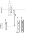
- FIG. 9 is a diagram showing an example of a description of the process of transitioning to the RRC_IDLE state by an L2 signal.
- specification TS38.321 describes transitioning the NCR to the RRC_IDLE state by an L2 signal.
- Figure 10 is a diagram showing an example of the description of parameters included in RRCRelease.
- specification TS38.331 describes the parameters used when transitioning the NCR to the RRC_IDLE state with RRCRelease.
- FIG. 11 is a diagram showing an example of a description of the paging process for the NCR. For example, paging for the NCR is described in specification TS38.331.
- FIG. 12 is a diagram showing an example of a description of the suspendConfig parameter.
- the specification TS38.331 describes the parameters included in the suspendConfig parameter.
- FIG. 13 is a diagram showing an example of the description of the operation when an RRCRelease including a suspendConfig parameter is received.
- specification TS38.331 describes the operation when an NCR receives an RRCRelease including a suspendConfig parameter.
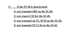
- FIG. 14 is a diagram showing an example of a description of PCell deactivation.
- specification TS38.321 describes PCell deactivation.
- Wireless communication system 100 Terminal device 110: CPU 120: storage 121: wireless communication program 130: memory 150: wireless communication circuit 200: base station device 210: CPU 220: Storage 221: Wireless communication control program 222: Relay control program 2221: State control module 230: Memory 250: Wireless communication circuit 300: Relay device 310: CPU 320: Storage 321: Relay program 322: State transition program 330: Memory 350: Wireless communication circuit 351: Wireless communication circuit
Landscapes
- Engineering & Computer Science (AREA)
- Computer Networks & Wireless Communication (AREA)
- Signal Processing (AREA)
- Mobile Radio Communication Systems (AREA)
Abstract
基地局装置と端末装置間の無線通信を中継する中継機能を有し、前記基地局装置によって前記中継機能を制御される中継装置であって、前記基地局装置から通信状態の遷移を指示する情報を含む信号を受信する受信部と、前記信号が第1識別子を含む第1信号である場合、通信状態を第2状態から第1状態に遷移するように制御する制御部とを有する。
Description
本発明は、中継装置、基地局装置、及び無線通信システムに関する。
無線通信システムでは、例えば、基地局装置から送信された信号(電波)を端末装置が受信することで、無線通信が実現する。しかし、端末装置の場所によっては、基地局装置からの電波が届かない(端末装置が受信できない)場合がある。そこで、基地局装置から受信した電波を増幅して送信する、リピータ(Repeater)と言われる中継装置が存在する。ユーザは、リピータを設置することで、ビルや物の影や基地局装置から遠方に位置するなどにより、電波が届かないところ不感地帯に増幅した電波を送信することができ、端末装置が無線通信できないエリアを減らすことができる。
しかし、リピータは、単純に電波を増幅するのみであり、端末装置の方向へのビームフォーミングや、増幅した電波の送信制御などを行うことができなかった。そこで、基地局装置からの制御機能やビームフォーミング機能を有する高機能のリピータであるNCR(Network Controlled Repeater)が、3GPP(登録商標)(Third Generation Partnership Project)のRel-18において検討されている。
リピータやNCRに関する技術としては、以下の先行技術文献に記載されている。
3GPP TS 36.133 V17.6.0
3GPP TS 36.211 V17.2.0
3GPP TS 36.212 V17.1.0
3GPP TS 36.213 V17.2.0
3GPP TS 36.214 V17.0.0
3GPP TS 36.300 V17.1.0
3GPP TS 36.321 V17.1.0
3GPP TS 36.322 V17.0.0
3GPP TS 36.323 V17.1.0
3GPP TS 36.331 V17.1.0
3GPP TS 37.324 V17.0.0
3GPP TS 37.340 V17.1.0
3GPP TS 38.133 V17.6.0
3GPP TS 38.201 V17.0.0
3GPP TS 38.202 V17.2.0
3GPP TS 38.211 V17.2.0
3GPP TS 38.212 V17.2.0
3GPP TS 38.213 V17.2.0
3GPP TS 38.214 V17.2.0
3GPP TS 38.215 V17.1.0
3GPP TS 38.300 V17.1.0
3GPP TS 38.321 V17.1.0
3GPP TS 38.322 V17.1.0
3GPP TS 38.323 V17.1.0
3GPP TS 38.331 V17.1.0
RP-213700
しかし、NCRについては検討段階であり、詳細な処理内容については未決定である。特に、NCRは、取りうる状態及び状態遷移については、決定していない。
そこで、一開示は、NCRの適切な状態遷移を実現できる中継装置、基地局装置、及び無線通信システムを提供する。
基地局装置と端末装置間の無線通信を中継する中継機能を有し、前記基地局装置によって前記中継機能を制御される中継装置であって、前記基地局装置から通信状態の遷移を指示する情報を含む信号を受信する受信部と、前記信号が第1識別子を含む第1信号である場合、通信状態を第2状態から第1状態に遷移するように制御する制御部とを有する。
一開示は、NCRの適切な状態遷移を実現できる。
[第1の実施の形態]
第1の実施の形態について説明する。
第1の実施の形態について説明する。
<無線通信システム10について>
図1は、無線通信システム10の構成例を示す図である。無線通信システム10は、基地局装置200、中継装置300、及び端末装置100を有する。
図1は、無線通信システム10の構成例を示す図である。無線通信システム10は、基地局装置200、中継装置300、及び端末装置100を有する。
端末装置100は、基地局装置200と無線接続し、データの送受信を行う通信装置であり、例えば、スマートフォンやタブレット端末である。また、端末装置100は、中継装置300と無線接続することで、中継装置300を介して、基地局装置200と通信を行う。
基地局装置200は、端末装置100と無線接続し、無線通信を行う通信装置であり、例えば、eNodeBやgNodeBである。基地局装置200は、例えば、様々な通信世代(例えば、4G、5GやBeyond5Gなど)に対応する。また、基地局装置200は、1台で構成されてもよいし、CU(Central Unit)とDU(Distributed Unit)などの複数台で構成されてもよい。
中継装置300は、基地局装置200からの電波を受信し、増幅した電波をビームフォーミングにて送信する通信装置であり、例えば、NCRである。中継装置300は、中継処理について、例えば、基地局装置200から制御される。なお、中継装置300が増幅できる電波(信号)は、複数台の基地局装置200に対応できてもよいが、本実施例においては、1台の基地局装置200に対応するものとする。
<中継装置300のソフトウェア構成例>
図2は、無線通信システム10における中継装置300のソフトウェア構成例を表す図である。中継装置300は、NCR-MT(Mobile Termination)301とNCR-Fwd(Forwarding)302を有する。
図2は、無線通信システム10における中継装置300のソフトウェア構成例を表す図である。中継装置300は、NCR-MT(Mobile Termination)301とNCR-Fwd(Forwarding)302を有する。
NCR-MT301は、コントロールリンク(Control Link)L1を介して、基地局装置200と無線通信し、サイド制御情報などの送受信を可能にする制御部である。コントロールリンクL1は、例えば、NR(New Radio)のUuインターフェイスが使用される。なお、サイド制御情報は、例えば、以下に説明するNCR-Fwd302の制御に関する情報が含まれる。
NCR-Fwd302は、バックホールリンク(Backhaul Link)L2とアクセスリンク(Access Link)L3を介して、基地局装置200及び端末装置100の間で信号(電波)の増幅と転送を実行する中継部である。NCR-Fwd302は、基地局装置200から受信したサイド制御情報に応じて、被制御され、中継処理を決定する。なお、転送とは、基地局装置200から受信した信号を増幅し、端末装置100に送信すること、及び端末装置100から受信した信号を増幅し、基地局装置200に送信することを含む。
<中継装置300の構成例>
図3は、中継装置300の構成例を示す図である。中継装置300は、CPU(Central Processing Unit)310、ストレージ320、メモリ330、無線通信回路350、及び無線通信回路351を有する。
図3は、中継装置300の構成例を示す図である。中継装置300は、CPU(Central Processing Unit)310、ストレージ320、メモリ330、無線通信回路350、及び無線通信回路351を有する。
ストレージ320は、プログラムやデータを記憶する、フラッシュメモリ、HDD(Hard Disk Drive)、又はSSD(Solid State Drive)などの補助記憶装置である。ストレージ320は、中継プログラム321及び状態遷移プログラム322を記憶する。
メモリ330は、ストレージ320に記憶されているプログラムをロードする領域である。また、メモリ330は、プログラムがデータを記憶する領域としても使用されてもよい。
無線通信回路350は、基地局装置200と無線通信を行う装置である。中継装置300は、無線通信回路350を介して、基地局装置200と信号の送受信を行う。
無線通信回路351は、端末装置100と無線通信を行う装置である。中継装置300は、無線通信回路351を介して、端末装置100と信号の送受信を行う。
CPU310は、ストレージ320に記憶されているプログラムを、メモリ330にロードし、ロードしたプログラムを実行し、各部を構築し、各処理を実現するプロセッサである。
CPU310は、中継プログラム321を実行することで、中継部を構築し、中継処理を行う。中継処理は、基地局装置200から制御信号を受信し、制御信号に従い、端末装置100に中継(増幅、転送)を行う処理である。
CPU310は、状態遷移プログラム322を実行することで、制御部及び受信部を構築し、状態遷移処理を行う。状態遷移処理は、基地局装置200からの状態遷移を指示する信号を受信し、基地局装置200の指示に従い状態を制御する処理である。また、状態遷移処理は、自律的に状態遷移する処理を含む。
<基地局装置200の構成例>
図4は、基地局装置200の構成例を表す図である。基地局装置200は、CPU210、ストレージ220、メモリ230、無線通信回路250を有する。
図4は、基地局装置200の構成例を表す図である。基地局装置200は、CPU210、ストレージ220、メモリ230、無線通信回路250を有する。
ストレージ220は、プログラムやデータを記憶する、フラッシュメモリ、HDD、又はSSDなどの補助記憶装置である。ストレージ220は、無線通信制御プログラム221及び中継制御プログラム222を記憶する。
メモリ230は、ストレージ220に記憶されているプログラムをロードする領域である。また、メモリ230は、プログラムがデータを記憶する領域としても使用されてもよい。
無線通信回路250は、端末装置100と無線通信を行う装置である。また、無線通信回路250は、中継装置300と無線通信を行ってもよい。
CPU210は、ストレージ220に記憶されているプログラムを、メモリ230にロードし、ロードしたプログラムを実行し、各部を構築し、各処理を実現するプロセッサである。
CPU210は、無線通信制御プログラム221を実行することで、通信部を構築し、無線通信制御処理を行う。無線通信制御処理は、端末装置100と無線通信を行う処理である。基地局装置200は、無線通信制御処理において、端末装置100と無線接続し、送信先に信号を送信したり、信号を受信したりする。また、無線通信制御処理は、中継装置300を介して、端末装置100と通信する処理を含む。
CPU210は、中継制御プログラム222を実行することで、受信部及び中継制御部を構築し、中継制御処理を行う。中継制御処理は、中継装置300が行う中継処理を制御する処理である。基地局装置200は、中継制御処理において、自装置と中継装置300との無線通信を行う。
CPU210は、中継制御プログラム222が有する状態制御モジュール2221を実行することで、受信部及び中継制御部を構築し、状態制御処理を行う。状態制御処理は、中継装置300の通信状態(NCR-MT301との通信状態)を制御する処理である。
<端末装置100の構成例>
図5は、端末装置100の構成例を表す図である。端末装置100は、CPU110、ストレージ120、メモリ130、無線通信回路150を有する。
図5は、端末装置100の構成例を表す図である。端末装置100は、CPU110、ストレージ120、メモリ130、無線通信回路150を有する。
ストレージ120は、プログラムやデータを記憶する、フラッシュメモリ、HDD、又はSSDなどの補助記憶装置である。ストレージ120は、無線通信プログラム121を記憶する。
メモリ130は、ストレージ120に記憶されているプログラムをロードする領域である。また、メモリ130は、プログラムがデータを記憶する領域としても使用されてもよい。
無線通信回路150は、基地局装置200と無線通信を行う装置である。また、無線通信回路150は、中継装置300と無線通信を行ってもよい。
CPU110は、ストレージ120に記憶されているプログラムを、メモリ130にロードし、ロードしたプログラムを実行し、各部を構築し、各処理を実現するプロセッサである。
CPU110は、無線通信プログラム121を実行することで、端末通信部を構築し、無線通信処理を行う。無線通信処理は、基地局装置200や中継装置300と無線通信を行う処理である。端末装置100は、無線通信処理において、基地局装置200や中継装置300と無線接続し、信号(メッセージ)の送受信を行うことで、無線通信を実現する。
<中継装置300の状態>
中継装置300は、例えば、コントロールリンクL1のRRC(Radio Resource Control)の接続状態に応じて、以下の状態を取り得る。
・RRC_IDLE状態
・RRC_INACTIVE状態
・RRC_CONNECTED状態
中継装置300は、例えば、コントロールリンクL1のRRC(Radio Resource Control)の接続状態に応じて、以下の状態を取り得る。
・RRC_IDLE状態
・RRC_INACTIVE状態
・RRC_CONNECTED状態
RRC_IDLE状態は、基地局装置200とRRC接続していない状態であり、CN(Core Network)ページング受信のためのページングチャネルの監視や、報知情報の受信などを行う。RRC_CONNECTED状態は、基地局装置200と無線接続し、中継装置300個別の信号の送受信を含む通信を、常時行うことができる状態である。RRC_INACTIVE状態は、基地局装置200と無線接続が一時停止(suspend)している状態であり、CN(Core Network)ページングや、RAN(Radio Access Network)ページング受信のためのページングチャネルの監視や、報知情報の受信などを行う。またRRC_INACTIVE状態において、中継装置300は、UE Inactive AS Contextと呼ばれる情報を保持する事により、基地局装置200とのRRC接続を再開(resume)できるようにする。UE Inactive AS Contextは例えば、中継装置300がRRC_CONNECTED状態からRRC_INACTIVE状態に遷移する前に使用していた、セキュリティ鍵の情報、セル設定情報、中継装置300個別の信号の送受信に使われる識別子の情報等を含む。
中継装置300は、RRC_IDLE状態、及びRRC_INACTIVE状態において、所定タイミングにおいてのみ、送受信回路を通電させればよいため、常時通信を行うために常時送受信回路を通電させておく必要があるRRC_CONECCTED状態よりも、電力消費を抑制することができる。
なお、コントロールリンクL1における状態遷移は、バックホールリンクL2とアクセスリンクL3の状態(接続状態)とは非同期である。バックホールリンクL2とアクセスリンクL3は、基地局装置200と端末装置100との通信に使用されるリンクであって、中継装置300(NCR-MT301)の制御対象とならない。
以降の説明において、RRC_IDLE状態、RRC_INACTIVE状態、及びRRC_CONNECTED状態を例に説明するが、状態はこれに限らない。RRC_IDLE状態は、例えば、個別の無線通信(ページングの取得を除く)を行っておらず、個別の無線通信開始時にはRRC接続が必要な状態であればよい。RRC_CONNECTED状態は、例えば、個別の無線通信(ページングの取得を除く)を行っておらず、個別の無線通信開始時にはRRC接続の再開が必要な状態であればよい。
<状態遷移>
中継装置300の状態遷移ついて説明する。以降、基地局装置200の指示(主導)による状態遷移、及び中継装置300の自律的に状態遷移、それぞれについて説明する。
中継装置300の状態遷移ついて説明する。以降、基地局装置200の指示(主導)による状態遷移、及び中継装置300の自律的に状態遷移、それぞれについて説明する。
<1.基地局装置主導の状態遷移>
基地局装置200が主導する状態遷移について説明する。
基地局装置200が主導する状態遷移について説明する。
<1.1 RRC_IDLE状態への遷移>
RRC_IDLE状態への遷移について説明する。NCR-MT301は、例えば、RRC_CONNECTED状態又はRRC_INACTIVE状態において、基地局装置200からの指示を受信し、RRC_IDLE状態に遷移する。
RRC_IDLE状態への遷移について説明する。NCR-MT301は、例えば、RRC_CONNECTED状態又はRRC_INACTIVE状態において、基地局装置200からの指示を受信し、RRC_IDLE状態に遷移する。
図6は、RRC_IDLE状態へと遷移するシーケンスの例を示す図である。中継装置300のNCR-MT301は、RRC_CONNECTED状態又はRRC_INACTIVE状態である(S10)。
基地局装置200は、NCR-MT301をRRC_IDLE状態に遷移させると判定する(S11)。基地局装置200は、例えば、NCR_Fwd302が、所定時間使用されていない(信号、メッセージの送受信がない)など、中継処理が所定時間行われていない場合、NCR-MT301をRRC_IDLE状態に遷移させると判定する。基地局装置200は、NCR_Fwd302の使用の有無を取得する方法として、例えば、NCR-Fwd302の使用頻度や通信量などの情報を含むレポートを、NCR_MT301から定期的に受信してもよい。
基地局装置200は、RRC_IDLE状態に遷移することを指示するシグナリングを、NCR-MT301に送信する(S12)。
シグナリングは、例えば、RRC_CONNECTED状態に遷移するときに使用するページング受信用識別子を含んでもよい。またシグナリングは、例えば、中継装置300で使用するタイマー値を含んでもよい。NCR-MT301は、例えば、タイマーが満了すると、再度RRC_CONNECTED状態(又はRRC_INACTIVE状態)に遷移する。またシグナリングにより、RRC_CONNECTEDに遷移するときに使用するセル情報(基地局装置200に関する情報を含む)を含んでも良い。
シグナリングは、例えば、L1(Layer1)シグナルやL2(Layer2)シグナルである。L1シグナルは、例えば、DCI(Downlink Control Information)である。L2シグナルは、例えばMAC CE(Control Element)である。
また、シグナリングは、例えば、RRCReleaseメッセージであってもよい。
NCR-MT301は、シグナリングを受信すると(S12)、RRC_IDLE状態へと遷移する(S13)。NCR_MT301は、例えば、シグナリングがL1の場合、PHY(PHYsical layer)から上位レイヤに通知し、RRCにおいて、無線接続を切断(解放)し、RRC_IDLE状態への遷移を行う。PHYの上位レイヤは、例えばMAC(Medium Access Control layer)である。またPHYの上位レイヤは、例えばRRCレイヤである。また、NCR_MT301は、例えば、シグナリングがL2の場合、MAC(Medium Access Control layer)から上位レイヤに通知し、RRCにおいて、無線接続を切断(解放)し、RRC_IDLE状態への遷移を行う。MACの上位レイヤは、例えばRRCレイヤである。また、NCR_MT301は、例えば、シグナリングがRRC Releaseの場合、RRCにおいて、無線接続を切断(解放)し、RRC_IDLE状態への遷移を行う。
<1.2 RRC_INACTIVE状態への遷移>
RRC_INACTIVE状態への遷移について説明する。NCR-MT301は、例えば、RRC_CONNECTED状態において、基地局装置200からの指示を受信し、RRC_INACTIVE状態に遷移する。
RRC_INACTIVE状態への遷移について説明する。NCR-MT301は、例えば、RRC_CONNECTED状態において、基地局装置200からの指示を受信し、RRC_INACTIVE状態に遷移する。
図7は、RRC_INACTIVE状態へと遷移するシーケンスの例を示す図である。中継装置300のNCR-MT301は、RRC_CONNECTED状態である(S20)。
基地局装置200は、NCR-MT301をRRC_INACTIVE状態に遷移させると判定する(S21)。基地局装置200における判定基準は、例えば、RRC_IDLEに遷移させる判定と同基準である。
基地局装置200は、RRC_INACTIVE状態に遷移することを指示するシグナリングを、NCR-MT301に送信する(S22)。
シグナリングは、例えば、suspendConfigパラメータを含むRRCReleaseメッセージである。suspendConfigパラメータは、例えば、中継装置300で使用するタイマー値を含んでもよい。NCR-MT301は、例えば、タイマーが満了すると、再度RRC_CONNECTED状態(又はRRC_IDLE状態)に遷移する。
なお、suspendConfigパラメータは、中継装置300にて使用しないパラメータ(情報要素)、例えば、RAN-NotificationAreaInfoとPeriodicRNAU-TimerValueを含まない。
中継装置300は、suspendConfigパラメータを含むRRCReleaseを受信した場合、UE Inactive AS Contextとして保持する情報から、中継装置300にて使用しない設定である、ROHC stateとQoS flow to DRB mapping rulesは除外してもよい。また、中継装置300は、UE Inactive AS Contextとして保持する情報から、中継装置300にて使用しない設定である、application layer measurement configurationも除外しても良い。
NCR-MT301は、シグナリングを受信すると(S22)、RRC_INACTIVE状態へと遷移する(S23)。
<1.3 RRC_CONNECTED状態への遷移>
RRC_CONNECTED状態への遷移について説明する。NCR-MT301は、例えば、RRC_IDLE状態又はRRC_INACTIVE状態において、基地局装置200からの指示を受信し、RRC_IDLE状態に遷移する。
RRC_CONNECTED状態への遷移について説明する。NCR-MT301は、例えば、RRC_IDLE状態又はRRC_INACTIVE状態において、基地局装置200からの指示を受信し、RRC_IDLE状態に遷移する。
図8は、RRC_CONNECTED状態へと遷移するシーケンスの例を示す図である。中継装置300のNCR-MT301は、RRC_IDLE状態又はRRC_INACTIVE状態である(S30)。
基地局装置200は、NCR-MT301をRRC_CONNECTED状態に遷移させると判定する(S31)。基地局装置200は、例えば、端末装置100へ送信するデータが発生した場合や、NCR-Fwd302への制御が必要となった場合など、NCR-MT301をRRC_CONNECTED状態に遷移させると判定する。
基地局装置200は、RRC_CONNECTED状態に遷移することを指示するページングを、NCR-MT301に送信する(S32)。ページングは、NCR-MT301が自身へのページングであることを認識できるページング受信用識別子を含む。
NCR-MT301は、ページングを受信すると(S32)、RRC Connection Establishmentプロシージャーを起動する(S33)。処理S33は、NCR-MT301に対してデータが発生する場合と、発生しない場合とで異なるため、それぞれについて説明する。なお、NCR-MT301に対してデータが発生する場合とは、制御メッセージ以外のデータ送信が発生する場合であり、例えば、中継装置300に対するソフトウェアアップデートなどである。
<MCR-MT301に対するデータが発生しない場合>
NCR-MT301は、のページング受信用識別子を上位レイヤ(NAS)に通知する事なく、直ちにRRC Connection Establishmentプロシージャーを起動し、RRCコネクションを確立する。ページング受信用識別子は、例えば、5G-S-TMSI、RRC_IDLE状態に遷移するときに受信した識別子、又は事前に設定されている中継装置300専用の識別子などである。中継装置300専用の識別子は、例えば、RRCコネクション確立時、基地局装置200に通知される。
NCR-MT301は、のページング受信用識別子を上位レイヤ(NAS)に通知する事なく、直ちにRRC Connection Establishmentプロシージャーを起動し、RRCコネクションを確立する。ページング受信用識別子は、例えば、5G-S-TMSI、RRC_IDLE状態に遷移するときに受信した識別子、又は事前に設定されている中継装置300専用の識別子などである。中継装置300専用の識別子は、例えば、RRCコネクション確立時、基地局装置200に通知される。
また、上位レイヤ(NAS)に通知する事なくRRCコネクションを確立するため、RRC Connection Establishmentプロシージャーの中で、NCR-MT301から基地局装置200に送信されるRRCメッセージである、RRCSetupCompleteメッセージに、専用NASメッセージパラメータ(DedicatedNAS-Message)を含めない。
<MCR-MT301に対するデータが発生する場合>
NCR-MT301は、のページング受信用識別子を上位レイヤ(NAS)に通知し、RRC Connection Establishmentプロシージャーを起動し、RRCコネクションを確立する。
NCR-MT301は、のページング受信用識別子を上位レイヤ(NAS)に通知し、RRC Connection Establishmentプロシージャーを起動し、RRCコネクションを確立する。
NCR-MT301は、データの発生有無をページングで判定する。例えば、データの有無に応じて、異なるページング受信用識別子が使用されてもよい。例えば、RRC-IDLE状態に遷移するときに受信した識別子、中継装置300専用識別子、及び5G-S-TMSIそれぞれが、データ有り又はデータ無しのいずれかに割り当てられてもよい。また、データ有りのページング、又はデータ無しのページングに、異なるページングオケージョンが定義されてもよい。
NCR-MT301は、RRC Connection Establishmentプロシージャーを起動することで、RRCコネクションを確立し、RRC_CONNECTED状態に遷移する(S34)。
<2.中継装置の自律的な状態遷移>
中継装置300の自律的な状態遷移について説明する。
中継装置300の自律的な状態遷移について説明する。
NCR-MT301は、無線状態の劣化などによって、RRC接続が切断され、RRC_IDLE状態に遷移する場合がある。このとき、NCR-MT301は、例えば、すぐにセルサーチを行い、RRC Connection Setupを行う。また、NCR-MT301は、例えば、決められた(設定された)時間の経過後に、セルサーチを行い、RRC Connection Setupを行ってもよい。また、NCR-MT301は、新たなページングを受信するのを待ってもよい。なお、MCR-MT301は、セルサーチを行うとき、事前に決められたセルをサーチしてもよい。
[第2の実施の形態]
次に、第2の実施の形態について説明する。第2の実施の形態では、中継装置300が、RRC_CONNECTED状態を維持したまま、どのように省電力を実現するかについて説明する。
次に、第2の実施の形態について説明する。第2の実施の形態では、中継装置300が、RRC_CONNECTED状態を維持したまま、どのように省電力を実現するかについて説明する。
第2の実施の形態では、PCell(Primary Cell)のdeactivation/dormantという概念を定義する。これにより、中継装置300は、省電力を実現する。
NCR-MT301は、deactivation/dormant時の動作として、例えば、以下の処理を行わない。
・SRS/UL-SCH/RACH/PUCCH送信
・CSIレポート送信
・SRS/UL-SCH/RACH/PUCCH送信
・CSIレポート送信
一方、NCR-MT301は、deactivation/dormant時の動作として、例えば、以下の処理を行う。
・PDCCHモニタリング
・BFD/BFR
・BFD/BFRを行う場合、BFDが検出された場合のRACH送信
・PDCCHモニタリング
・BFD/BFR
・BFD/BFRを行う場合、BFDが検出された場合のRACH送信
なおPDCCHのモニタリングは、例えば、リラックスモード(所定タイミングにおいてのみPDCCHを受信するモード)でもよい。
[その他の実施の形態]
第1及び第2の実施の形態に記載された要件は、それぞれ組み合わせてもよい。また、第1及び第2の実施の形態に記載された要件は、無線通信システムの要件、周辺の状況、電波状況などに応じて、使い分けられてもよい。
第1及び第2の実施の形態に記載された要件は、それぞれ組み合わせてもよい。また、第1及び第2の実施の形態に記載された要件は、無線通信システムの要件、周辺の状況、電波状況などに応じて、使い分けられてもよい。
なお、第1及び第2の実施の形態において、シーケンス上のメッセージは、順序通りに行われる必要はなく、順序が入れ変わってもよい。また、シーケンス上のメッセージは、一部行われなくてもよい。
また第1及び第2の実施の形態において、中継装置300の機能や処理、制御として記述されているものは、基地局装置200の機能や処理であっても良い。また第1及び第2の実施の形態において、基地局装置200の機能や処理として記述されているものは、中継装置300の機能や処理であっても良い。なお、第1及び第2の実施の形態では、装置の一例を記載したが、本開示の方式は中継装置、基地局装置など限定されるものではなく、他の電子機器、たとえば、自動車、電車、飛行機、人工衛星等に搭載される電子機器、ドローン等に搭載される電子機器、ロボット、AV機器、生活家電、オフィス機器、自動販売機、その他生活機器、工業用機器などの装置に適用出来る。
また、第1及び第2の実施の形態では、4G、5GやBeyond5Gにおける装置及びシステムの機能や処理、制御などを説明したが、本開示の方式が適用されるのはこれらに限るものでは無い。例えば、第6世代や第7世代等、世代の異なる装置及びシステムに本開示の形式を適用しても良い。
また、上記実施の形態に限定されず、種々変更して実施することが可能である。
また、第1及び第2の実施の形態に関して図面を参照して詳述してきたが、具体的な構成はこの形態に限られるものではない。
<仕様書への反映>
第1及び第2の実施の形態について、3GPPの仕様書に反映される例を示す。以降の図では、太字のアンダーラインで、追加仕様が示される。また、図で示される追加仕様における、仕様書名、章番、項番、名称、値、挿入箇所などについては、あくまで一例であり、これに限られない。
第1及び第2の実施の形態について、3GPPの仕様書に反映される例を示す。以降の図では、太字のアンダーラインで、追加仕様が示される。また、図で示される追加仕様における、仕様書名、章番、項番、名称、値、挿入箇所などについては、あくまで一例であり、これに限られない。
図9は、L2シグナルでRRC_IDLE状態へ遷移する処理についての記載の例を示す図である。例えば、仕様書TS38.321に、L2シグナルでNCRをRRC_IDLE状態に遷移させることが記載される。
図10は、RRCReleaseに含むパラメータの記載の例を示す図である。例えば、仕様書TS38.331に、RRCReleaseでNCRをRRC_IDLE状態に遷移させる際のパラメータが記載される。
図11は、NCRに対するページングの処理についての記載の例を示す図である。例えば、仕様書TS38.331に、NCRに対するページングについて記載される。
図12は、suspendConfigパラメータに関する記載の例を示す図である。例えば、仕様書TS38.331に、suspendConfigパラメータに含まれるパラメータについて記載される。
図13は、suspendConfigパラメータを含むRRCRelease受信時の動作の記載の例を示す図である。例えば、仕様書TS38.331に、NCRがsuspendConfigパラメータを含むRRCReleaseを受信したときの動作が記載される。
図14は、PCellのdeactivationについての記載の例を示す図である。例えば、仕様書TS38.321に、PCellのdeactivationに関して記載される。
10 :無線通信システム
100 :端末装置
110 :CPU
120 :ストレージ
121 :無線通信プログラム
130 :メモリ
150 :無線通信回路
200 :基地局装置
210 :CPU
220 :ストレージ
221 :無線通信制御プログラム
222 :中継制御プログラム
2221 :状態制御モジュール
230 :メモリ
250 :無線通信回路
300 :中継装置
310 :CPU
320 :ストレージ
321 :中継プログラム
322 :状態遷移プログラム
330 :メモリ
350 :無線通信回路
351 :無線通信回路
100 :端末装置
110 :CPU
120 :ストレージ
121 :無線通信プログラム
130 :メモリ
150 :無線通信回路
200 :基地局装置
210 :CPU
220 :ストレージ
221 :無線通信制御プログラム
222 :中継制御プログラム
2221 :状態制御モジュール
230 :メモリ
250 :無線通信回路
300 :中継装置
310 :CPU
320 :ストレージ
321 :中継プログラム
322 :状態遷移プログラム
330 :メモリ
350 :無線通信回路
351 :無線通信回路
Claims (7)
- 基地局装置と端末装置間の無線通信を中継する中継機能を有し、前記基地局装置によって前記中継機能を制御される中継装置であって、
前記基地局装置から通信状態の遷移を指示する情報を含む信号を受信する受信部と、
前記信号が第1識別子を含む第1信号である場合、通信状態を第2状態から第1状態に遷移するように制御する制御部と、を有する
中継装置。 - 前記第1信号は、ページングメッセージであり、
前記第2状態は、無線接続がされていない状態であり、
前記第1状態は、無線接続されている状態である
請求項1記載の中継装置。 - 前記制御部は、前記制御において、無線接続を実行する
請求項2記載の中継装置。 - 前記第2状態は、RRC_IDLE状態であり、
第3状態は、RRC_CONNECTED状態である
請求項2記載の中継装置。 - 前記第1識別子は、前記中継装置が前記第2状態に遷移するときに、前記基地局装置から受信した識別子である
請求項1記載の中継装置。 - 基地局装置と端末装置間の無線通信を中継する中継機能を有する中継装置を制御する前記基地局装置であって、
前記中継装置に対して、第1識別子を含む第1信号を送信する送信部と、
前記第1信号を送信することで、前記中継装置に、前記基地局装置との通信状態を第2状態から第1状態に遷移させる中継制御部とを有する
基地局装置。 - 基地局装置と、端末装置と、前記端末装置と前記基地局装置間の無線通信を中継する中継機能を有する中継装置と、を有する無線通信システムであって、
前記基地局装置は、前記中継装置に対して、第1識別子を含む第1信号を送信し、
前記中継装置は、前記第1信号を受信し、前記基地局装置との通信状態を第2状態から第1状態に遷移する
無線通信システム。
Priority Applications (1)
| Application Number | Priority Date | Filing Date | Title |
|---|---|---|---|
| PCT/JP2022/037347 WO2024075232A1 (ja) | 2022-10-05 | 2022-10-05 | 中継装置、基地局装置、及び無線通信システム |
Applications Claiming Priority (1)
| Application Number | Priority Date | Filing Date | Title |
|---|---|---|---|
| PCT/JP2022/037347 WO2024075232A1 (ja) | 2022-10-05 | 2022-10-05 | 中継装置、基地局装置、及び無線通信システム |
Publications (1)
| Publication Number | Publication Date |
|---|---|
| WO2024075232A1 true WO2024075232A1 (ja) | 2024-04-11 |
Family
ID=90607874
Family Applications (1)
| Application Number | Title | Priority Date | Filing Date |
|---|---|---|---|
| PCT/JP2022/037347 Ceased WO2024075232A1 (ja) | 2022-10-05 | 2022-10-05 | 中継装置、基地局装置、及び無線通信システム |
Country Status (1)
| Country | Link |
|---|---|
| WO (1) | WO2024075232A1 (ja) |
Citations (2)
| Publication number | Priority date | Publication date | Assignee | Title |
|---|---|---|---|---|
| JP2016532337A (ja) * | 2013-09-29 | 2016-10-13 | 富士通株式会社 | ページング方法、ネットワーク装置及び通信システム |
| WO2018198276A1 (ja) * | 2017-04-27 | 2018-11-01 | 富士通株式会社 | 基地局装置、端末装置、無線通信システム、及び端末移動方法 |
-
2022
- 2022-10-05 WO PCT/JP2022/037347 patent/WO2024075232A1/ja not_active Ceased
Patent Citations (2)
| Publication number | Priority date | Publication date | Assignee | Title |
|---|---|---|---|---|
| JP2016532337A (ja) * | 2013-09-29 | 2016-10-13 | 富士通株式会社 | ページング方法、ネットワーク装置及び通信システム |
| WO2018198276A1 (ja) * | 2017-04-27 | 2018-11-01 | 富士通株式会社 | 基地局装置、端末装置、無線通信システム、及び端末移動方法 |
Non-Patent Citations (3)
| Title |
|---|
| "3rd Generation Partnership Project; Technical Specification Group Radio Access network; Study on NR network-controlled repeaters; (Release 18)", 3GPP TR 38.867, no. V18.0.0, 23 September 2022 (2022-09-23), pages 1 - 21, XP052211146 * |
| FUJITSU: "Discussion on C-plane aspects for NCR-MT", 3GPP TSG-RAN WG2 MEETING #119BIS ELECTRONIC R2-2209630, 30 September 2022 (2022-09-30), XP052262959 * |
| NEC: "Control plane signaling and procedures of network-controlled repeater", 3GPP TSG-RAN WG2 #119BIS-E R2-2210135, 30 September 2022 (2022-09-30), XP052263458 * |
Similar Documents
| Publication | Publication Date | Title |
|---|---|---|
| EP3753178B1 (en) | Bandwidth part switching and phy configuration alignment | |
| JP7845423B2 (ja) | 通信方法、端末装置、及びネットワーク装置 | |
| EP2468050B1 (en) | Discontinuous reception for multi-component carrier system | |
| EP3493642B1 (en) | Terminal state conversion methods and apparatuses | |
| CN106465270B (zh) | 用户终端以及无线通信方法 | |
| US9603184B2 (en) | Tune back coordination with connected mode discontinuous receive | |
| JP2022511342A (ja) | 無線通信システムにおける間欠受信 | |
| US20240179781A1 (en) | Method and Device for Transmitting Reference Signal | |
| CN107006056A (zh) | 用于具有突发性交互式业务的用户设备的延迟减少 | |
| EP4240051A1 (en) | Measurement adjustment method, and terminal | |
| CN116097810B (zh) | 用于新空口的特殊小区休眠的方法和用户装备 | |
| WO2022042752A1 (zh) | 物理下行控制信道的监听方法、装置和设备 | |
| EP3987883A1 (en) | Adaptation of active-time pdcch monitoring using short discontinuous reception (drx) | |
| TW202241112A (zh) | 用以處理非小資料傳輸(non-sdt)資料之方法、裝置及媒體 | |
| EP4521824A1 (en) | Method executed by user equipment, and user equipment | |
| US20250393056A1 (en) | Method performed by user equipment, and user equipment | |
| EP3002985B1 (en) | Method and apparatus for handling release of simultaneous communication with multiple base stations and related communication device | |
| WO2024075232A1 (ja) | 中継装置、基地局装置、及び無線通信システム | |
| CN115499854A (zh) | Gap处理方法、装置、终端及可读存储介质 | |
| US20240072954A1 (en) | Method and apparatus for processing bandwidth parts and terminal | |
| US20230337315A1 (en) | Reference signal configuration method and apparatus, and terminal | |
| JP5997661B2 (ja) | 中継器装置及び中継器のスリープ制御方法 | |
| EP4376499A1 (en) | Node state control method and apparatus and related device | |
| WO2022183980A1 (zh) | Sl csi报告的处理方法、装置及设备 | |
| WO2023011455A1 (zh) | 辅小区组的控制方法、装置及终端 |
Legal Events
| Date | Code | Title | Description |
|---|---|---|---|
| 121 | Ep: the epo has been informed by wipo that ep was designated in this application |
Ref document number: 22961419 Country of ref document: EP Kind code of ref document: A1 |
|
| NENP | Non-entry into the national phase |
Ref country code: DE |
|
| 122 | Ep: pct application non-entry in european phase |
Ref document number: 22961419 Country of ref document: EP Kind code of ref document: A1 |
|
| NENP | Non-entry into the national phase |
Ref country code: JP |