WO2024070752A1 - 画像処理装置、方法及びプログラム - Google Patents
画像処理装置、方法及びプログラム Download PDFInfo
- Publication number
- WO2024070752A1 WO2024070752A1 PCT/JP2023/033649 JP2023033649W WO2024070752A1 WO 2024070752 A1 WO2024070752 A1 WO 2024070752A1 JP 2023033649 W JP2023033649 W JP 2023033649W WO 2024070752 A1 WO2024070752 A1 WO 2024070752A1
- Authority
- WO
- WIPO (PCT)
- Prior art keywords
- image
- virtual space
- processing device
- captured
- information
- Prior art date
- Legal status (The legal status is an assumption and is not a legal conclusion. Google has not performed a legal analysis and makes no representation as to the accuracy of the status listed.)
- Ceased
Links
Images


Classifications
-
- G—PHYSICS
- G06—COMPUTING OR CALCULATING; COUNTING
- G06T—IMAGE DATA PROCESSING OR GENERATION, IN GENERAL
- G06T19/00—Manipulating three-dimensional [3D] models or images for computer graphics
- G06T19/20—Editing of three-dimensional [3D] images, e.g. changing shapes or colours, aligning objects or positioning parts
-
- G—PHYSICS
- G06—COMPUTING OR CALCULATING; COUNTING
- G06T—IMAGE DATA PROCESSING OR GENERATION, IN GENERAL
- G06T19/00—Manipulating three-dimensional [3D] models or images for computer graphics
-
- G—PHYSICS
- G06—COMPUTING OR CALCULATING; COUNTING
- G06T—IMAGE DATA PROCESSING OR GENERATION, IN GENERAL
- G06T15/00—Three-dimensional [3D] image rendering
- G06T15/10—Geometric effects
- G06T15/20—Perspective computation
-
- G—PHYSICS
- G06—COMPUTING OR CALCULATING; COUNTING
- G06T—IMAGE DATA PROCESSING OR GENERATION, IN GENERAL
- G06T19/00—Manipulating three-dimensional [3D] models or images for computer graphics
- G06T19/006—Mixed reality
-
- G—PHYSICS
- G06—COMPUTING OR CALCULATING; COUNTING
- G06T—IMAGE DATA PROCESSING OR GENERATION, IN GENERAL
- G06T2219/00—Indexing scheme for manipulating 3D models or images for computer graphics
- G06T2219/20—Indexing scheme for editing of 3D models
- G06T2219/2004—Aligning objects, relative positioning of parts
-
- G—PHYSICS
- G06—COMPUTING OR CALCULATING; COUNTING
- G06T—IMAGE DATA PROCESSING OR GENERATION, IN GENERAL
- G06T2219/00—Indexing scheme for manipulating 3D models or images for computer graphics
- G06T2219/20—Indexing scheme for editing of 3D models
- G06T2219/2016—Rotation, translation, scaling
Definitions
- the present invention relates to an image processing device, method, and program, and in particular to an image processing device, method, and program that provides a virtual space.
- Patent documents 1 to 4 describe technology for viewing images captured in real space in a virtual space.
- One embodiment of the technology disclosed herein provides an image processing device, method, and program that can provide an excellent image viewing space.
- An image processing device including a processor configured to acquire position information in a virtual space that reproduces a real space, display an object image representing a first image in the virtual space based on a first image associated with the position information among a group of images captured in the real space, and display a second image of the virtual space observed from a viewpoint corresponding to the position information on a display unit.
- An image processing device in which the processor is configured to display an object image at a position in virtual space corresponding to the position in real space where the first image was captured.
- An image processing device configured to change the virtual space to one corresponding to the image information of the first image when the position indicated by the position information moves to a position within a second distance range from the display position of the object image.
- An image processing device configured to display the object image in accordance with the orientation in which the first image was captured.
- An image processing device configured to display the object image at a size corresponding to the angle of view of the first image.
- An image processing device in which the processor is configured to determine the shooting environment of the first image based on the image information of the first image, and change the virtual space to one corresponding to the determined shooting environment.
- An image processing device according to (2), (10) or (11), in which the processor is configured to convert the virtual space data into virtual space data that constructs a different virtual space.
- An image processing device (10), (11), (12) or (13), in which the processor is configured to display multiple object images in the virtual space when multiple first images exist, accept a selection of an object image, and change the virtual space to correspond to the image information of the first image represented by the selected object image.
- An image processing device configured to accept a selection of an object image by treating an object image present in the line of sight as the selected object image.
- An image processing device (10), (11), (12), (13), (14), (15), (16) or (17), in which the processor is configured to display a selected object image and other object images in different display modes.
- An image processing method including the steps of acquiring position information in a virtual space that reproduces a real space, displaying an object image representing a first image in the virtual space based on a first image associated with the position information from among a group of images captured in the real space, and displaying a second image of the virtual space observed from a viewpoint corresponding to the position information on a display unit.
- An image processing program that causes a computer to perform the following functions: acquiring position information within a virtual space that reproduces a real space; displaying an object image representing a first image within the virtual space based on a first image associated with the position information among a group of images captured in the real space; and displaying a second image of the virtual space observed from a viewpoint corresponding to the position information on a display unit.
- FIG. 1 is a diagram showing an example of a system configuration of an image viewing system.
- FIG. 1 is a block diagram showing an example of a configuration of a display terminal.
- Block diagram of the main functions of the control unit of the display terminal FIG. 1 is a diagram showing an example of a hardware configuration of an image processing apparatus.
- Block diagram of the main functions of the image processing device Image search concept
- FIG. 1 is a diagram showing an example of virtual space data stored in a virtual space database
- FIG. 13 is a diagram showing an example of an image of a virtual space displayed on a display unit of a display terminal.
- a flowchart showing a procedure for providing a virtual space by an image processing device A flowchart showing a procedure for providing a virtual space by an image processing device.
- FIG. 11 is a diagram showing another example of display of a captured image.
- FIG. 11 is a diagram showing another example of display of a captured image.
- Block diagram of main functions of an image processing device for changing a virtual space Conceptual diagram of judging captured images during viewing Flowchart of processing procedures related to changes in virtual space Flowchart showing the procedure of the image capture environment determination process
- Conceptual diagram of judging captured images during viewing FIG. 13 is a diagram showing an example of an image selection operation by a user;
- FIG. 13 is a diagram showing another example of displaying a captured image in a virtual space.
- FIG. 13 is a diagram showing another example of displaying a captured image in a virtual space.
- This disclosure provides a new image viewing system that utilizes digital twins.
- FIG. 1 is a diagram showing an overview of an image viewing system according to the present disclosure.
- a virtual space that recreates a real space such as a tourist spot is provided to the user via a head mounted display (HMD).
- HMD head mounted display
- the user can move freely within the virtual space just as they would within the real space. If an image taken in the real space exists, when the user approaches a position in the virtual space that corresponds to the position in the real space where the image was taken, the image is displayed in the virtual space.
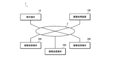
- FIG. 2 is a diagram showing an example of a system configuration of an image viewing system.
- the image viewing system 1 of this embodiment is configured to include a display terminal 10 that displays images of a virtual space, an image processing device 100 that provides images of the virtual space to the display terminal 10, and an image transmission terminal 200 that transmits images captured in real space to the image processing device 100.
- the display terminal 10 and the image processing device 100 are connected to be able to communicate with each other via a network 2.
- the image transmission terminal 200 and the image processing device 100 are connected to be able to communicate with each other via the network 2.
- the image sending terminal 200 is composed of, for example, a computer with a communication function (for example, a personal computer, etc.), a mobile terminal (for example, a smartphone, a mobile phone, a tablet terminal, etc.), an image capturing device with a communication function (for example, a digital camera, etc.), etc.
- a computer with a communication function for example, a personal computer, etc.
- a mobile terminal for example, a smartphone, a mobile phone, a tablet terminal, etc.
- an image capturing device with a communication function for example, a digital camera, etc.
- the image sending terminal 200 sends (uploads) images captured in real space to the image processing device 100.
- the images to be sent may be images captured by other devices. If the image sending terminal itself has a shooting function (for example, a smartphone with a camera function), it can send images captured by the device itself to the image processing device 100.
- a shooting function for example, a smartphone with a camera function
- the image transmitted by the image transmitting terminal 200 to the image processing device 100 is accompanied by at least information indicating the shooting position (shooting position information).
- the shooting position information is composed of information that can uniquely identify a position in real space.
- the shooting position information can be composed of information on the latitude and longitude of the point where the image was taken.
- the shooting position information can further include altitude information.
- the manner in which information such as the shooting location is attached to an image is not particularly limited. For example, it can be attached to an image as metadata.
- information such as the shooting location can be attached to an image as tag information.
- GPS Global Positioning System
- GPS information latitude, longitude, altitude, etc.
- electronic compass geomagnetic sensor
- the display terminal 10 is configured as, for example, a non-transparent HMD that is worn on the user's head and covers the user's field of vision with a display unit.
- a non-transparent HMD that is worn on the user's head and covers the user's field of vision with a display unit.
- FIG. 3 is a block diagram showing an example of the configuration of a display terminal.
- the display terminal 10 has a control unit 11, a communication unit 12, an operation unit 13, a sensor unit 14, a display unit 15, an audio input unit 16, and an audio output unit 17.
- the control unit 11 functions as an arithmetic processing device and control device, and controls the overall operation of the display terminal 10 in accordance with various programs.
- the control unit 11 is composed of, for example, a computer equipped with a processor and memory.
- the processor is realized by electronic circuits such as a CPU (Central Processing Unit).
- the memory includes a ROM (Read Only Memory) that stores programs and various data, etc., a RAM (Random Access Memory) used as a work area, etc., and a flash memory.
- the communication unit 12 is connected to the network 2 by wired or wireless means, and communicates with the image processing device 100 on the network.
- the communication unit 12 is connected to the network 2 by, for example, a wired/wireless LAN (Local Area Network), Wi-Fi (registered trademark), Bluetooth (registered trademark), a mobile communication network 5G (5th Generation/fifth generation mobile communication system), 4G (4th Generation/fourth generation mobile communication system), LTE (Long Term Evolution), etc.
- the operation unit 13 accepts operation instructions from the user and outputs the operation contents to the control unit 11. In this embodiment, movement within the virtual space is performed by operating the operation unit 13.
- the movement operation can be configured to be performed, for example, by an operation device capable of directional input.
- an operation device capable of directional input for example, a hand controller, joystick, etc. can be used.
- the operation unit 13 can include known operation devices such as a push switch, lever, volume, pedal switch, keyboard, mouse, trackpad, trackball, gesture input device, etc.
- the sensor unit 14 detects at least the tilt (tilt on the three axes X, Y and Z) of the headset or goggles (part worn on the head) (3 Degrees of Freedom; 3DoF/3 degrees of freedom). In other words, it detects the orientation of the head.
- the sensor unit 14 may further be configured to detect the position of the headset or goggles in three-dimensional space (6DoF/6 degrees of freedom). In other words, it detects the position of the head in addition to the orientation. Since this type of sensing technology is well known, detailed explanations are omitted. As an example, a configuration can be adopted in which a gyro sensor, an acceleration sensor, a geomagnetic sensor, etc.
- the sensor unit 14 may also include a biosensor that detects the user's bioinformation (for example, pulse, heart rate, sweat, blood pressure, body temperature, breathing, electromyography, brain waves, etc.), a gaze detection sensor that detects the user's gaze in the headset or goggles, etc.
- the sensing information detected by the sensor unit 14 is output to the control unit 11.
- the display unit 15 When the display terminal 10 is configured as an HMD, the display unit 15 has a left eye screen and a right eye screen corresponding to the user's left and right eyes, and displays images corresponding to each screen (left eye image and right eye image).
- the screen of the display unit 15 is configured, for example, as a display panel such as an LCD (Liquid Crystal Display) or an OLED (Organic Light Emitting Diode) display, or a laser scanning display such as a retinal direct imaging display.
- the voice input unit 16 is composed of, for example, a microphone, and collects the voice uttered by the user.
- the audio output unit 17 is composed of, for example, headphones or earphones, and reproduces audio signals.
- Figure 4 is a block diagram of the main functions of the control unit of the display terminal.
- control unit 11 of the display terminal 10 functions as a position recognition unit 11A, a gaze direction recognition unit 11B, a communication control unit 11C, a display control unit 11D, etc.
- the position recognition unit 11A recognizes the user's current position (user position) in the virtual space based on the operation information of the operation unit 13. For example, the user position is recognized from the direction and amount of movement from an origin position set in the virtual space. Positions in the virtual space correspond one-to-one with positions in the real space.
- the gaze direction recognition unit 11B recognizes the user's current gaze direction in the virtual space based on the state of the head (orientation, position, etc.) detected by the sensor unit 14.
- the communication control unit 11C controls communication with the image processing device 100.
- Current user position information (user position information) recognized by the position recognition unit 11A and information on the user's current line of sight direction recognized by the line of sight direction recognition unit (user line of sight information) are transmitted to the image processing device 100 via the communication unit 12 under the control of the communication control unit 11C.
- the image processing device 100 generates an image to be displayed on the display unit 15 based on information transmitted from the display terminal 10.
- the communication control unit 11C receives the image for display transmitted from the image processing device 100 via the communication unit 12.
- the display control unit 11D controls the display of the display unit 15.
- the display image received from the image processing device 100 is displayed on the display unit 15 under the control of the display control unit 11D.
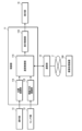
- FIG. 5 is a diagram illustrating an example of a hardware configuration of an image processing apparatus.
- the image processing device 100 includes a CPU 111, a ROM 112, a RAM 113, an auxiliary storage device 114, an input device 115, an output device 116, and a communication interface (I/F) 117.
- this type of configuration can be realized by a computer.
- the image processing device 100 functions as an image processing device by the CPU 111, which is a processor, executing a predetermined program (image processing program).
- the program executed by the CPU 111 is stored in the ROM 112 or the auxiliary storage device 114.
- the auxiliary storage device 114 constitutes the storage section of the image processing device 100.
- the auxiliary storage device 114 is constituted, for example, by a HDD (Hard Disk Drive), SSD (Solid State Drive), etc.
- the input device 115 constitutes the operation section of the image processing device 100.
- the input device 115 is composed of, for example, a keyboard, a mouse, a touch panel, etc.
- the output device 116 constitutes the display unit of the image processing device 100.
- the output device 116 is constituted, for example, by a KCD, an OLED display, etc.
- the communication interface 117 is connected to the network 2 via a wired or wireless connection, and communicates with the image processing device 100 and the image sending terminal 200 on the network.
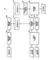
- Figure 6 is a block diagram of the main functions of the image processing device.
- the image processing device 100 mainly has the function of collecting captured images from the image sending terminal 200 and the function of providing a virtual space to the display terminal 10.
- the image processing device 100 functions as a captured image acquisition unit 100A and a captured image management unit 100B.
- the captured image acquisition unit 100A acquires captured images sent from the image sending terminal 200 via the network 2.
- the captured image management unit 100B stores the captured images acquired by the captured image acquisition unit 100A in a captured image database (Data Base; DB) 114A.
- the captured image database 114A is saved in, for example, the auxiliary storage device 114.
- information on the shooting location is added to the captured images sent from the image sending terminal 200.
- the captured image management unit 100B stores the captured images in the captured image database 114A in association with the shooting location information.
- the captured image management unit 100B also numbers each captured image and stores them in the captured image database 114A.
- the multiple captured images stored in the captured image database 114A are an example of a group of images captured in real space.
- the image processing device 100 functions as a user information acquisition unit 100C, a visual field area calculation unit 100D, a captured image search unit 100E, a virtual space data selection unit 100F, and a display image generation unit 100G, etc.
- the user information acquisition unit 100C acquires information on the user's current state (user information).
- the user information includes user position information (information on the user's current position in the virtual space) and user gaze information (information on the current direction of the user's gaze in the virtual space). This information is acquired from the display terminal 10 via the network 2. The acquired information is added to the captured image search unit 100E and the visual field calculation unit 100D.
- the user position information is an example of position information in a virtual space that reproduces real space.
- the visual field calculation unit 100D calculates the user's visual field (field of view) in the virtual space based on user information (user position information and user line of sight information). More specifically, it calculates the visual field of an avatar, which is the user's alter ego in the virtual space. This visual field corresponds to the display range of the image of the virtual space to be displayed on the display unit 15. Information on the calculated visual field (display range information) is added to the captured image search unit 100E and the display image generation unit 100G.
- the captured image search unit 100E searches the captured image database 114A for captured images (related images) related to the user's current location based on the user's current location information (user location information) in the virtual space and information on the user's current field of view.
- Figure 7 shows a conceptual diagram of image search.
- the figure shows a plan view of a virtual space and a real space corresponding to the virtual space.
- the symbol Pv0 in the figure indicates the position of the user (avatar) in the virtual space.
- the symbol Pr0 indicates the position in real space corresponding to the position Pv0 in the virtual space.
- the symbols Pr1 to Pr8 indicate the positions in real space where images were taken (the positions where the images taken at those positions exist).
- the symbols Pv1 to Pv8 indicate the positions in virtual space corresponding to the positions Pr1 to Pr8 in the real space.
- the arrow DG indicates the direction of the user's line of sight in the virtual space.
- the shaded area FV indicates an area within a radius R1 based on the user's current position Pv0 in the virtual space and within the current user's field of view (visual field).
- the user's horizontal field of view in the virtual space is a range of 100° to the left and right (total of 200°) based on the line of sight direction DG.
- the shaded area FR is the area in real space that corresponds to the area FV in virtual space.
- the captured image search unit 100E searches for images that were taken within a radius R1 (less than or equal to the distance threshold R1) based on the position Pr0 in the real space corresponding to the user's current position Pv0 in the virtual space and that were taken within the current field of view.
- the unit searches for images that were taken within a circle of radius R1 from the position of XX degrees XX minutes XX seconds north latitude and XX degrees XX minutes XX seconds east longitude and that were taken within the current field of view (searching for images taken within the real space region FR that corresponds to the virtual space region FV).
- the images taken at positions Pr1, Pr3, Pr5, and Pr7 are images taken within the radius R1.
- the images taken at positions Pr1 and Pr3 are images taken within a range corresponding to the current field of view. Therefore, the images taken at positions Pr1 and Pr3 are searched for.
- the retrieved captured image is added to the display image generating unit 100G.
- the retrieved captured image is an example of a first image related to the location information.
- the range of radius R1 is also an example of a range of the first distance.
- the range of region FR is an example of a range of a first distance from a position in real space that corresponds to the position information in virtual space, and a range in real space that corresponds to the range of a second image in virtual space.
- the virtual space data selection unit 100F selects the virtual space data to be used.
- a plurality of pieces of virtual space data are stored in advance in the virtual space database 114B. Therefore, the virtual space data selection unit 100F selects the virtual space data to be used from the plurality of pieces of virtual space data stored in the virtual space database 114B.
- the virtual space database 114B is saved in, for example, the auxiliary storage device 114.
- FIG. 8 is a diagram showing an example of virtual space data stored in a virtual space database. This diagram shows an example of virtual space data for providing multiple types of virtual spaces with different environments for one real space.
- multiple sets of virtual space data are prepared for different combinations of seasons (spring, summer, fall, winter), weather conditions (sunny, cloudy, rainy) and time periods (morning, noon, evening, night).
- Each set of virtual space data is a reproduction of the same real space, but with different seasons, weather conditions and time periods.
- virtual space database 114B is configured so that multiple types of virtual space data are recorded for one real space, allowing virtual spaces of different environments to be constructed.
- Virtual space database 114B records virtual space data that can reproduce at least one real space. Each piece of virtual space data is recorded in association with information about the real space to be reproduced.
- the real space to be reproduced (the real space to be provided to the user as a virtual space) is selected by the user, for example.
- the virtual space data to be used is selected according to the current date and time of the area where the display terminal 10 is used, for example.
- the season of the virtual space data to be used is selected from the current date and time, with March to May being spring, June to August being summer, September to November being autumn, and December to February being winter.
- the time period of the virtual space data to be used is selected from the current date and time, with 6:00 to 9:00 being morning, 9:00 to 15:00 being day, 15:00 to 18:00 being evening, and 18:00 to 6:00 the next day being night.
- the virtual space data corresponding to "daytime" in "winter” is selected.
- the weather is selected as the default (for example, sunny). Therefore, in this case, "JP040102" is selected as the virtual space data (if the default setting for "weather” is “sunny”).
- the weather may be selected randomly.
- Information on the current date and time is obtained from the system or the display terminal 10.
- the selected virtual space data is added to the display image generating unit 100G.
- the configuration may be such that predetermined virtual space data or virtual space data selected by the user is selected.
- the display image generating unit 100G generates an image of the virtual space (display image) to be provided to the display terminal 10 based on the virtual space data selected by the virtual space data selecting unit 100F and the information on the visual field calculated by the visual field calculating unit 100D.
- This display image is an image of the virtual space observed from the viewpoint of the user at the user's (avatar's) current position in the virtual space.
- the display image generating unit 100G generates a display image in which the captured image is displayed in the virtual space.
- FIG. 9 shows an example of an image of a virtual space displayed on the display unit of a display terminal.
- the image of the virtual space (display image) IMV displayed on the display unit 15 of the display terminal 10 is an image of the field of view cut out from the image of the virtual space constructed from the virtual space data.
- the captured image IMO is displayed at a position Pv in the virtual space corresponding to the shooting position Pr in the real space.
- the captured image IMO is displayed in the virtual space at a predetermined size. That is, it is placed in the virtual space as a planar object of a predetermined size and is visually recognized by the user. Therefore, the closer the user is to the display position (shooting position), the larger the image is displayed.
- the captured image IMO is displayed at a predetermined height from the ground (for example, at approximately the height of the line of sight of an adult). Therefore, the captured image IMO is displayed floating in the air in the virtual space.
- the captured image IMO is displayed facing the user (avatar).
- the captured image IMO displayed in the virtual space is an example of an object image.
- the display image generated by the display image generating unit 100G is transmitted to the display terminal 10 via the network 2.
- the display terminal 10 receives the display image transmitted from the image processing device 100 and displays it on the display unit 15. This allows the user to view an image of the virtual space that changes in conjunction with the user's movements.
- the display image is an example of a second image.
- FIG. 10 and 11 are flow charts showing the procedure for providing a virtual space by an image processing device.
- Fig. 10 shows the procedure up to displaying an image of the virtual space on the display unit 15 of the display terminal 10.
- Fig. 11 shows the operation procedure after the display starts.
- step S1 information on the real space to be provided is acquired (step S1).
- information on real spaces that can be provided as virtual spaces is displayed in a list on the display unit 15 of the display terminal 10.
- the user selects the desired real space from the displayed list.
- the selected information is transmitted to the image processing device 100 as information on the real space to be provided.
- step S2 information on the current date and time is obtained.
- the information on the current date and time is obtained from the system or the display terminal 10.
- virtual space data of the virtual space to be provided is selected based on the acquired real space information and current date and time information (step S3). As described above, for example, if the current date and time is 12:00 on January 1st, virtual space data corresponding to "daytime" in "winter” is selected. Note that the weather that is set as the default is selected.
- a display image is generated based on the selected virtual space data (step S4). That is, an image of the virtual space to be displayed on the display unit 15 of the display terminal 10 is generated. This image is generated based on a reference position (origin position or starting position) that is set in advance in the virtual space. It is also generated based on a reference line of sight direction. That is, it is generated as an image that is observed when facing a specified direction at the reference position.
- the generated display image is provided to the display terminal 10 via the network 2 and is displayed on the display unit 15 of the display terminal 10 (step S5).
- step S11 it is determined whether the user's state has changed. In other words, it is determined whether the user has moved or changed the direction of their line of sight.
- a search is performed for captured images (related images) related to the user's current location, and the found related images are displayed in the virtual space.
- the related images are searched for in the captured image database 114A.
- the search and display are performed according to the following procedure.
- step S14 it is determined whether the selected captured image (selected image) is a relevant image (step S14). It is determined whether the image was captured within a radius R1 range based on a position in real space corresponding to the user's current position in the virtual space, and whether it was captured within the current field of view. In this case, it is first determined whether the selected image was captured within a radius R1 range. If the image was not captured within the radius R1 range, it is determined that it is not a relevant image. On the other hand, if the image was captured within the radius R1 range, it is then determined whether the image was captured within the current field of view. If the image was not captured within the current field of view, it is determined that it is not a relevant image. On the other hand, if the image was captured within the current field of view, it is determined that it is a relevant image.
- step S15 it is determined whether the selected image is currently being displayed. In other words, it is determined whether the selected image is already being displayed in the virtual space.
- the selected image is already being displayed, it continues to be displayed.
- the selected image is displayed in the virtual space (step S16).
- the image is displayed at a position corresponding to the position at which it was photographed. In other words, it is displayed at a position in the virtual space that corresponds to the position at which it was photographed in real space.
- the image is also displayed in the virtual space at a predetermined size, facing the user directly (see Figure 9).
- step S14 If it is determined in step S14 that the selected image is not a related image, it is determined whether or not the selected image is currently being displayed (step S20). In other words, it is determined whether or not the selected image is currently being displayed in the virtual space despite being a related image. If the selected image is currently being displayed, the display is terminated (step S21).
- step S19 it is determined whether or not an instruction to end the display has been given by turning off the power, etc.
- step S11 determines whether or not an instruction to end the display has been given by turning off the power, etc.
- step S11 determines whether or not an instruction to end the display has been given by turning off the power, etc.
- step S11 determines whether or not the user has exited the virtual space. If it is determined that the user has exited the virtual space, the process ends. On the other hand, if it is determined that the user has not exited the virtual space, the process returns to step S11, and it is again determined whether or not there has been a change in state.
- each captured image is displayed one after another in the virtual space in conjunction with the user's movement.
- Each captured image is displayed at a position corresponding to the position in real space where the image was captured. This makes it possible to present how each captured image was captured in an easy-to-understand manner. It also allows the user to deepen their understanding of the captured images and enjoy a better viewing experience. Furthermore, each captured image disappears when the user moves away from the display position (capture position) by more than a certain distance, so the display in the virtual space does not become cluttered.
- the captured image is displayed in the virtual space facing the user. If information on the shooting direction can be acquired from the captured image, the captured image may be displayed in accordance with the direction in which the captured image was shot.
- Figure 12 is a conceptual diagram of the display of a captured image.
- (A) in the figure is a conceptual diagram of the display of the captured image IMO when information on the shooting direction cannot be obtained from the captured image IMO.
- (B) in the figure is a conceptual diagram of the display of the captured image IMO when information on the shooting direction can be obtained from the captured image IMO.
- the captured image IMO is displayed facing the user (avatar) U. More specifically, the captured image IMO is displayed perpendicular to the depth direction of the screen.
- the captured image IMO is displayed in the virtual space according to the shooting direction when the image was captured. Specifically, the captured image IMO is displayed perpendicular to the direction of the optical axis L when the image was captured.
- Information about the shooting direction is obtained from information attached to the captured image (e.g., tag information).
- the shooting direction may be estimated by image recognition.
- FIG. 13 is a flowchart showing the process for displaying a captured image.
- step S31 information on the shooting direction of the captured image to be displayed is obtained.
- the information on the shooting direction is obtained from information attached to the captured image.
- the information on the shooting direction is obtained by image recognition.
- step S32 it is determined whether or not shooting direction information exists. In other words, it is determined whether or not shooting direction information has been acquired.
- the captured image is displayed in the virtual space in accordance with the shooting direction (step S33). That is, as shown in FIG. 12(B), the captured image IMO is displayed perpendicular to the shooting direction (direction of the optical axis L).
- the captured image is displayed in the virtual space in the normal display form (step S34). That is, as shown in FIG. 12(A), the captured image IMO is displayed facing the user.
- the captured image is displayed in virtual space according to the orientation in which it was taken. This allows for a deeper understanding of how the displayed image was taken.
- the captured image may be displayed in the virtual space at the height when it was taken.
- the user may be allowed to choose whether or not to display the image in accordance with the shooting direction.
- the captured image is displayed in a virtual space at a preset size. If information on the angle of view can be obtained from the captured image, the captured image may be displayed in the virtual space at a size corresponding to the angle of view.
- Figure 14 is a conceptual diagram of the display of a captured image.
- Figures (A) and (B) show examples of two images captured at different angles of view.
- Figure (A) shows an example of an image captured at a wider angle of view than Figure (B). More specifically, if the angle of view of the captured image IMO1 shown in Figure (A) is ⁇ 1 and the angle of view of the captured image IMO2 shown in Figure (B) is ⁇ 2, this shows an example of a case where ⁇ 1> ⁇ 2.
- the information on the angle of view of the captured image is obtained directly from the attached information. If information on the angle of view is not attached to the captured image, it is obtained using other information attached to the captured image.
- FIG. 15 is a flowchart showing the process for displaying a captured image.
- step S41 information on the angle of view of the captured image to be displayed is obtained.
- the information on the angle of view is obtained from information attached to the captured image. At this time, if the information on the angle of view cannot be obtained directly from the attached information, it is obtained by calculation.
- step S42 it is determined whether or not information on the angle of view is present. In other words, it is determined whether or not the information on the angle of view has been obtained.
- the captured image is displayed in the virtual space at a size according to the angle of view (step S43).
- the captured image is displayed in the virtual space at a specified display size (default display size) (step S44). In other words, the image is displayed in the virtual space at a predetermined size.
- the captured image is displayed in the virtual space at a size that corresponds to the angle of view. This allows you to understand the angle of view at which the displayed image was taken, and therefore allows you to correctly understand the size of the subject.
- the display size of a captured image may become too large or too small depending on the image.
- an image captured with a super telephoto lens may be displayed too small.
- an image captured with a super wide-angle lens including a fisheye lens
- images with an angle of view equal to or less than a threshold can be configured to be displayed at a uniformly specified size (minimum display size).
- images with an angle of view equal to or greater than a threshold can be configured to be displayed at a uniformly specified size (maximum display size).
- the captured image may be displayed according to the orientation in which it was taken.
- the captured image is displayed according to the orientation in which it was taken, and the captured image is displayed at a size according to the angle of view.
- the environment of the virtual space to be provided to the user is determined based on information on the current date and time of the area in which the display terminal 10 is used, but the method of determining the environment of the virtual space to be provided to the user is not limited to this.
- a virtual space of a predetermined environment may be provided to the user.
- the environment of the virtual space to be displayed may be arbitrarily selected and set by the user. For example, the season, weather, and time zone of the virtual space to be provided may all be selected and set by the user.
- FIG. 16 shows another example of the display of a captured image.
- the figure shows an example of the case where related images exist and are displayed together at a specified position in the virtual space.
- the example shown in the figure shows an example of the case where the captured images IMO are displayed in a vertical row in the right corner.
- a mark Mv may be displayed at a position in the virtual space corresponding to the capture position of each captured image IMO so that the capture position can be identified.
- each mark Mv may be displayed in a different color, and the corresponding captured image IMO may be displayed in a frame of the same color so that the correspondence between each captured image IMO and each mark Mv can be identified.
- FIG. 17 shows another example of the display of a captured image.
- This figure shows an example of a case where images taken within a radius R1 based on a position in real space that corresponds to the user's current position in the virtual space are extracted as related images and displayed in the virtual space.
- Images taken within the current field of view are displayed in the virtual space in accordance with the shooting position.
- images taken outside the field of view are displayed in a specified area.
- the example shown in FIG. 17 shows a case where the captured images IMO are displayed in a vertical row in the right corner.
- a map Mp may be displayed in the virtual space, and the approximate display position of each captured image may be indicated on the map Mp.
- the virtual space also changes to match the captured image that the user is viewing. For example, if the image that the user is viewing is an image of the autumn season, the season in the virtual space also changes to autumn.
- Figure 18 is a block diagram of the main functions of an image processing device with respect to changing the virtual space.
- the image processing device 100 of this embodiment further has the functions of a viewing image determination unit 100H and an image analysis unit 100I.
- the viewed image determination unit 100H determines which captured image the user is viewing from among the captured images displayed in the virtual space.
- the viewed image determination unit 100H determines which captured image is being viewed based on the user's current position information (user position information) in the virtual space and information on the captured image being displayed in the virtual space.
- Figure 19 is a conceptual diagram of how captured images are judged during viewing.
- the figure shows a plan view of the virtual space.
- the symbol Pv0 in the figure indicates the current position of the user (avatar) in the virtual space.
- the symbols Pi1 to Pi3 indicate the display positions of the captured images in the virtual space.
- the example shown in the figure is a case where three captured images are displayed in the virtual space.
- images located within a radius R2 are considered to be images currently being viewed by the user, and are extracted from among the captured images currently being displayed.
- Radius R2 is set to a value smaller than radius R1 (R2 ⁇ R1). In other words, an image currently being viewed is considered to be an image currently being viewed when the user approaches the captured image displayed in the virtual space by a certain distance or more.
- the captured image that is displayed closest to the user's current position Pv0 is considered to be the image that the user is viewing.
- two captured images (an image captured at position Pi2 and an image captured at position Pi3) are displayed within a range of radius R2.
- Position Pi2 is closer to the user than position Pi3. Therefore, in this case, the captured image displayed at position Pi2 is considered to be the captured image being viewed.
- the range of radius R2 is an example of the range of the second distance.
- determining the captured image being viewed is essentially the same as determining the captured image being selected by the user. In other words, it is the same as determining the image that the user has selected to view.
- the image analysis unit 100I analyzes the image information of the captured image. In other words, it analyzes the contents of what is being captured. In particular, in this embodiment, it analyzes the image information and determines the shooting environment.
- the shooting environment here refers to the environment of the real space in which the image is captured.
- the shooting environment includes at least one of the season, weather, and time of day. In this embodiment, the season, weather, and time of day of the captured image are determined.
- Analysis of image information includes analysis of incidental information in addition to image analysis. In other words, it includes analyzing incidental information to determine the shooting environment.
- Analysis of image information by image analysis employs, for example, a method of determining the shooting environment by image recognition. In this embodiment, the shooting environment is determined by analyzing incidental information.
- the season, weather, and time of day of a captured image can be roughly determined from the location and date and time of the image. For example, if the image was taken in Japan, the time period can be determined from the date and time of the image if 6:00 to 9:00 is morning, 9:00 to 15:00 is daytime, 15:00 to 18:00 is evening, and 18:00 to 6:00 the next day is night. Similarly, if the image was taken in Japan, the season can be determined from the date and time of the image if March to May is spring, June to August is summer, September to November is autumn, and December to February is winter.
- the weather can be determined, for example, by referring to a database (weather database) that records past weather conditions in various locations. Therefore, if the image is accompanied by information on the location and date and time of the image, the shooting environment (season, weather, and time of day) of the image can be determined from this information.
- the image analysis unit 100I analyzes information (e.g., meta information) attached to the captured image and determines the shooting environment. The determined shooting environment information is added to the virtual space data selection unit 100F.
- information e.g., meta information
- the shooting environment cannot be determined, and in this case, it is deemed impossible to determine. Also, if a determination cannot be made for some items, it is deemed impossible to determine (no information) for that item. For example, if the weather cannot be determined, it is deemed impossible to determine the weather.
- the virtual space data selection unit 100F selects the virtual space data to be used. As described above, the standard virtual space data is selected based on the current date and time of the area where the display terminal 10 is used. On the other hand, if there is a photographed image that the user is viewing, the virtual space data corresponding to the photographed image being viewed is selected. The virtual space data selection unit 100F selects the virtual space data to be used based on the analysis result of the photographed image's shooting environment by the image analysis unit 100I. In other words, the virtual space data to be used is selected based on the determined season, weather, and time of the photographed image. The virtual space data selection unit 100F searches the virtual space database 114B for the corresponding virtual space data and selects the virtual space data to be used. For example, if the season determined from the photographed image is "spring", the weather is "sunny”, and the time of day is "daytime”, the virtual space data of "JP010102" is selected as shown in FIG. 8.
- a search is performed using a predefined default setting for that item. For example, if the "season” cannot be determined (if there is no information), the corresponding virtual space data is searched for using the default seasonal information for "season” (for example, "spring").
- the default setting may be configured to be set by the user. Alternatively, for items that cannot be determined, the current setting may be used. For example, if the "season" cannot be determined, the seasonal information for the currently displayed virtual space may be used to search for virtual space data.
- the display image generating unit 100G generates an image of the virtual space (display image) to be provided to the display terminal 10 based on the virtual space data selected by the virtual space data selecting unit 100F and the information on the visual field calculated by the visual field calculating unit 100D. In this embodiment, if there is a photographed image being viewed by the user, an image of the virtual space that matches the environment of the photographed image is generated.
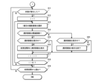
- FIG. 20 is a flowchart of a processing procedure relating to a change in virtual space.
- step S51 it is determined whether or not a photographed image is being displayed. In other words, it is determined whether or not a photographed image is being displayed in the currently displayed virtual space.
- step S52 If there is a captured image being displayed, it is determined whether or not there is a captured image being viewed (step S52). In this embodiment, the presence or absence of an image within a radius R2 of the user's current position is determined to determine whether or not there is a captured image being viewed.
- the captured image closest to the user's current position will be regarded as the captured image being viewed.
- the image information of the captured image being viewed is analyzed (step S53).
- the supplementary information of the captured image being viewed is analyzed to determine the shooting environment.
- FIG. 21 is a flowchart showing the steps of the process for determining the shooting environment.
- step S53_1 it is determined whether or not the season can be determined. In this embodiment, whether or not the season can be determined is determined based on the presence or absence of information on the shooting location and shooting date and time. If information on the shooting location and shooting date and time can be obtained, it is determined that the season can be determined.
- the seasonal data is set to the determined content (step S53_2). On the other hand, if the season cannot be determined, the seasonal data is set to "none" (step S53_3).
- step S53_4 it is determined whether or not the weather can be determined.
- whether or not the weather can be determined is determined based on the presence or absence of information on the shooting location and shooting date and time. If information on the shooting location and shooting date and time can be obtained, it is determined that the weather can be determined. As described above, the weather is determined from the shooting location and shooting date and time by referring to the weather database.
- the weather data is set to the determined content (step S53_5). On the other hand, if the weather cannot be determined, the weather data is set to "none" (step S53_6).
- step S53_7 it is determined whether or not it is possible to determine the time period. In this embodiment, it is determined whether or not it is possible to determine the time period based on the presence or absence of information on the shooting date and time.
- the time period data is set to the determined content (step S53_8). On the other hand, if the time period cannot be determined, the time period data is set to "none" (step S53_9).
- Virtual space data is selected based on the determined shooting environment (step S54). That is, based on the set season, weather, and time zone data, the corresponding virtual space data is searched for in the virtual space database 114B, and the virtual space data of the virtual space to be changed is selected. For example, if the season data is set to "spring”, the weather data is set to "sunny”, and the time zone data is set to "daytime”, the virtual space data of "JP010102" is selected as shown in FIG. 8. For items with “none” data, the data set by default is used. For example, if the season data is “spring”, the weather data is “none”, and the time zone data is "daytime”, the virtual space data is searched for with the weather data set by default (for example, "sunny”).
- step S56 it is determined whether or not the virtual space needs to be changed. If the selected virtual space data is the same as the virtual space data of the virtual space currently being provided, it is determined that no change is necessary. In this case, the virtual space is not changed and the current display continues. On the other hand, if the selected virtual space data is different from the virtual space data of the virtual space currently being provided, it is determined that a change is necessary.
- the virtual space to be provided is changed (step S56).
- an image of the virtual space to be provided to the display terminal 10 (display image) is generated based on the selected virtual space data and provided to the display terminal 10.
- the image of the virtual space provided is an image that reproduces the environment of the image the user is viewing. This can improve the sense of realism.
- step S57 it is determined whether or not the user has exited the virtual space. If it is determined that the user has exited the virtual space, the process ends. On the other hand, if it is determined that the user has not exited the virtual space, the process returns to step S51, and the processes from step S51 onwards are carried out again.
- step S58 it is determined whether the virtual space being displayed is a standard virtual space (step S58).
- the standard virtual space is the virtual space environment when display is started.
- the virtual space to be provided is set based on information about the current date and time of the area in which the display terminal 10 is used. Therefore, it is determined whether the image of the virtual space being displayed is an image of the virtual space set based on the current date and time of the area in which it is used.
- step S59 If the image of the virtual space being displayed is not the standard virtual space, it is changed to the standard virtual space (step S59). Therefore, when the user stops viewing the captured image displayed in the virtual space (when the user moves away from the captured image being viewed by more than the distance threshold R2), the virtual space is returned to the standard virtual space.
- the image viewing system of this embodiment if an image taken in real space exists, when the user approaches the shooting position of the captured image, the captured image is displayed at the shooting position.
- the display switches to a virtual space corresponding to the shooting environment of the captured image. In other words, the display switches to a virtual space that reproduces the shooting environment.
- the virtual environment is returned to the original environment. Furthermore, when the user moves away, the captured image disappears from the display.
- the virtual space provided changes according to the captured image being viewed. This improves the sense of realism when viewing the captured image. This provides an even better viewing experience.
- the image capturing environment can be determined by image recognition.
- the image capturing environment can be determined using a trained model that has been machine-learned to determine the image capturing environment from an image.
- the shooting environment is determined to be the season, weather, and time of day, but the information determined to be the shooting environment is not limited to these. For example, wind direction, wind speed, etc. may also be determined. Each item may also be classified in more detail for determination.
- the environment of the virtual space is changed by switching the virtual space data to be used, but the method of changing the virtual space is not limited to this.
- the environment of the virtual space can be changed by processing the image of the virtual space provided.
- the environment of the virtual space can be changed by adding an effect to the image.
- a plurality of effects corresponding to typical weather conditions are prepared in advance, and a weather effect corresponding to the weather of the captured image being viewed can be added to the image of the virtual space to change the weather of the virtual space.
- the effect itself is a known technology, so a detailed description thereof will be omitted.
- an effect can be added to an image by filter processing.
- the environment of the virtual space provided can be changed by combining switching of the virtual space data used with effects.
- the season can be handled by switching the virtual space data
- the time of day and weather can be handled by effects.
- the captured image displayed closest to the user is regarded as the image being viewed, but the method of determining the image being viewed is not limited to this.
- the captured image present in the user's line of sight may be regarded as the image being viewed and detected.
- Figure 22 is a conceptual diagram of how captured images are judged during viewing.
- the figure shows a plan view of the virtual space.
- the symbol Pv0 in the figure indicates the current position of the user (avatar) in the virtual space.
- the arrow DG indicates the direction of the user's gaze in the virtual space.
- the shaded area FD indicates the user's gaze area. In other words, it indicates the area where the user is directing their gaze and gazing at it.
- the gaze area FD is a range of ⁇ degrees horizontally based on the gaze direction DG.
- the symbols Pi1 to Pi3 indicate the display positions of the captured images in the virtual space.
- the example shown in the figure is a case where three captured images are displayed in the virtual space.
- the image located within the gaze area FD is considered to be the image being viewed by the user, and is extracted from the captured images being displayed.
- the captured image displayed at position Pi2 is considered to be the captured image being viewed.
- the captured image displayed closest to the user's current position Pv0 is considered to be the image the user is viewing.
- the captured image that is in the user's line of sight can be extracted and used as the image being viewed.
- the image within the gaze area FD (the image the user is directing his or her gaze at) is considered to be the image being viewed, but the image being viewed may be determined by limiting it to images located within a specified range from the user's current position. In other words, an image that exists in the direction of the user's gaze and within a specified distance may be considered to be the image being viewed.
- FIG. 23 shows an example of a user's image selection operation.
- the figure shows an example in which the hand Ha of an avatar, which represents the user, is displayed in a virtual space, and an image is selected with the hand Ha.
- the user selects an image by touching the captured image IMO displayed in the virtual space with the hand Ha.
- the virtual space changes to one corresponding to that photographed image IMO.
- the virtual space changes to the original environment.
- the virtual space changes to the original environment.
- the virtual space changes to one corresponding to the newly selected photographed image.
- the image being viewed may be manipulated by the hand Ha displayed in the virtual space.
- the image may be enlarged or reduced by performing a pinch-out or pinch-in operation (gesture) on the displayed image.
- FIG. 24 is a diagram showing another example of displaying a captured image in a virtual space.
- This figure shows an example in which two captured images IMO3 and IMO4 exist in relation to the user's current location.
- One captured image, IMO3 is the image being viewed, and the other captured image, IMO4, is the image not being viewed.
- the captured image IMO3 being viewed and the captured image IMO4 not being viewed are displayed in different display modes.
- the example shown in FIG. 24 shows an example of a case where the captured image other than the captured image being viewed is displayed in a semi-transparent state (the captured image IMO4 is displayed in a semi-transparent state).
- FIG. 25 shows another example of the display of a captured image in a virtual space.
- Figure 25 shows an example of grouping images taken in the same environment.
- the example shows images classified into two groups.
- the position at which the image is displayed can be, for example, the shooting position of the image that represents each group.
- the image that represents each group can be, for example, the image with the most recent shooting date and time, the image with the oldest shooting date and time, the image that has been viewed the most, etc.
- the user may be allowed to set these at their own discretion.
- the image information of the captured image may be analyzed to determine the era in which the captured image was captured, and the virtual space may be changed to correspond to the era in which the captured image was captured. In this way, various information can be obtained from the image, and the virtual space can be changed based on the obtained information. Also, as described above, the method of analyzing the image is not particularly limited, and various methods can be adopted.
- the display terminal 10 may be configured to output audio corresponding to the image information of the captured image.
- it may be configured to output background music (BGM) corresponding to the content being captured.
- BGM background music
- BGM may be prepared for each piece of virtual space data, and the BGM may be changed in conjunction with changes in the virtual space.
- the display terminal 10 is configured as an HMD, but the configuration of the display terminal is not limited to this.
- the display terminal may be configured to present an image of the virtual space on a non-wearable display such as a flat panel display.
- operations on the display terminal 10 may be performed using a controller, gestures, voice input, etc.
- the image processing device 100 is configured to be placed on a network, but the configuration of the image processing device 100 is not limited to this.
- the image processing device 100 may be directly connected to the display terminal 10 via a wired or wireless connection.
- the display terminal 10 may have the functions of the image processing device 100.
- the captured images are collected from a plurality of image transmitting terminals 200 via the network 2, but the method of collecting or acquiring the captured images is not limited to this. Images posted on SNS or the like may also be acquired.
- the captured image is not limited to a so-called still image, but also includes a video.
- the shooting position is determined using the supplementary information, as in the case of a still image, and the video is displayed at a position corresponding to the determined shooting position.
- the image of the first frame is displayed.
- playback can be started. The determination of whether or not the video is being viewed is made in the same manner as in the case of a still image.
- the virtual space can be changed simultaneously (including almost simultaneously) with the start of playback of the image, and the virtual space can be returned to the original space when playback ends.
- videos can be distinguished by displaying them with a specified mark.
- Preview playback or digest playback is possible.
- Preview playback is a function that plays the first few seconds of a video.
- Digest playback is a function that plays a shortened version of the video.
- the functions realized by the image processing device are realized by various processors.
- the various processors include a CPU and/or a GPU (Graphic Processing Unit) which is a general-purpose processor that executes a program and functions as various processing units, a Programmable Logic Device (PLD) such as an FPGA (Field Programmable Gate Array) which is a processor whose circuit configuration can be changed after manufacture, and a dedicated electric circuit such as an ASIC (Application Specific Integrated Circuit) which is a processor having a circuit configuration designed exclusively for executing a specific process.
- PLD Programmable Logic Device
- FPGA Field Programmable Gate Array
- ASIC Application Specific Integrated Circuit
- a single processing unit may be configured with one of these various processors, or may be configured with two or more processors of the same or different types.
- a single processing unit may be configured with multiple FPGAs, or a combination of a CPU and an FPGA.
- multiple processing units may be configured with one processor.
- first there is a form in which one processor is configured with a combination of one or more CPUs and software, as represented by computers used for clients and servers, and this processor functions as multiple processing units.
- a processor is used to realize the functions of the entire system, including multiple processing units, with a single IC (Integrated Circuit) chip, as represented by system on chip (SoC).
- SoC system on chip
Landscapes
- Engineering & Computer Science (AREA)
- Theoretical Computer Science (AREA)
- Physics & Mathematics (AREA)
- Computer Graphics (AREA)
- General Physics & Mathematics (AREA)
- Computer Hardware Design (AREA)
- General Engineering & Computer Science (AREA)
- Software Systems (AREA)
- Architecture (AREA)
- Computing Systems (AREA)
- Geometry (AREA)
- Processing Or Creating Images (AREA)
Priority Applications (3)
| Application Number | Priority Date | Filing Date | Title |
|---|---|---|---|
| JP2024550084A JPWO2024070752A1 (https=) | 2022-09-30 | 2023-09-15 | |
| CN202380069375.0A CN119948529A (zh) | 2022-09-30 | 2023-09-15 | 图像处理装置、方法及程序 |
| US19/078,249 US20250209768A1 (en) | 2022-09-30 | 2025-03-12 | Image processing apparatus, image processing method, and image processing program |
Applications Claiming Priority (2)
| Application Number | Priority Date | Filing Date | Title |
|---|---|---|---|
| JP2022-157584 | 2022-09-30 | ||
| JP2022157584 | 2022-09-30 |
Related Child Applications (1)
| Application Number | Title | Priority Date | Filing Date |
|---|---|---|---|
| US19/078,249 Continuation US20250209768A1 (en) | 2022-09-30 | 2025-03-12 | Image processing apparatus, image processing method, and image processing program |
Publications (1)
| Publication Number | Publication Date |
|---|---|
| WO2024070752A1 true WO2024070752A1 (ja) | 2024-04-04 |
Family
ID=90477476
Family Applications (1)
| Application Number | Title | Priority Date | Filing Date |
|---|---|---|---|
| PCT/JP2023/033649 Ceased WO2024070752A1 (ja) | 2022-09-30 | 2023-09-15 | 画像処理装置、方法及びプログラム |
Country Status (4)
| Country | Link |
|---|---|
| US (1) | US20250209768A1 (https=) |
| JP (1) | JPWO2024070752A1 (https=) |
| CN (1) | CN119948529A (https=) |
| WO (1) | WO2024070752A1 (https=) |
Citations (4)
| Publication number | Priority date | Publication date | Assignee | Title |
|---|---|---|---|---|
| JPH11122638A (ja) * | 1997-10-15 | 1999-04-30 | Oki Electric Ind Co Ltd | 画像処理装置および画像処理方法ならびに画像処理プログラムが記録されたコンピュータ読み取り可能な情報記録媒体 |
| JP2013120606A (ja) * | 2011-12-08 | 2013-06-17 | Samsung Electronics Co Ltd | 携帯端末機におけるコンテンツ表示装置及び方法 |
| JP2015228050A (ja) * | 2014-05-30 | 2015-12-17 | ソニー株式会社 | 情報処理装置および情報処理方法 |
| JP2018142230A (ja) * | 2017-02-28 | 2018-09-13 | キヤノンマーケティングジャパン株式会社 | 情報処理装置、情報処理システム、情報処理方法及びプログラム |
-
2023
- 2023-09-15 JP JP2024550084A patent/JPWO2024070752A1/ja active Pending
- 2023-09-15 WO PCT/JP2023/033649 patent/WO2024070752A1/ja not_active Ceased
- 2023-09-15 CN CN202380069375.0A patent/CN119948529A/zh active Pending
-
2025
- 2025-03-12 US US19/078,249 patent/US20250209768A1/en active Pending
Patent Citations (4)
| Publication number | Priority date | Publication date | Assignee | Title |
|---|---|---|---|---|
| JPH11122638A (ja) * | 1997-10-15 | 1999-04-30 | Oki Electric Ind Co Ltd | 画像処理装置および画像処理方法ならびに画像処理プログラムが記録されたコンピュータ読み取り可能な情報記録媒体 |
| JP2013120606A (ja) * | 2011-12-08 | 2013-06-17 | Samsung Electronics Co Ltd | 携帯端末機におけるコンテンツ表示装置及び方法 |
| JP2015228050A (ja) * | 2014-05-30 | 2015-12-17 | ソニー株式会社 | 情報処理装置および情報処理方法 |
| JP2018142230A (ja) * | 2017-02-28 | 2018-09-13 | キヤノンマーケティングジャパン株式会社 | 情報処理装置、情報処理システム、情報処理方法及びプログラム |
Also Published As
| Publication number | Publication date |
|---|---|
| US20250209768A1 (en) | 2025-06-26 |
| CN119948529A (zh) | 2025-05-06 |
| JPWO2024070752A1 (https=) | 2024-04-04 |
Similar Documents
| Publication | Publication Date | Title |
|---|---|---|
| US12112443B2 (en) | Display control apparatus, display control method, and program | |
| US11636644B2 (en) | Output of virtual content | |
| US10832448B2 (en) | Display control device, display control method, and program | |
| CN106255866B (zh) | 通信系统、控制方法以及存储介质 | |
| US11170580B2 (en) | Information processing device, information processing method, and recording medium | |
| US10127632B1 (en) | Display and update of panoramic image montages | |
| JP6408019B2 (ja) | 画像デバイスにおける写真構図および位置ガイダンス | |
| US9710132B2 (en) | Image display apparatus and image display method | |
| CN110546601B (zh) | 信息处理装置、信息处理方法和程序 | |
| JPWO2016203792A1 (ja) | 情報処理装置、情報処理方法及びプログラム | |
| JP2009118134A (ja) | 自動撮像装置、自動撮像制御方法、画像表示システム、画像表示方法、表示制御装置、表示制御方法 | |
| WO2019044135A1 (ja) | 情報処理装置、情報処理方法、およびプログラム | |
| WO2019150880A1 (ja) | 情報処理装置、情報処理方法、及びプログラム | |
| CN114207557A (zh) | 虚拟和物理相机的位置同步 | |
| CN108140124A (zh) | 提示信息确定方法、装置、电子设备和计算机程序产品 | |
| US9628552B2 (en) | Method and apparatus for digital media control rooms | |
| US20240284041A1 (en) | Information processing apparatus and information processing method | |
| WO2024070752A1 (ja) | 画像処理装置、方法及びプログラム | |
| US12272008B2 (en) | Generating a three-dimensional environment based on an image | |
| GB2639137A (en) | Electronic device | |
| CN116132790B (zh) | 录像方法和相关装置 |
Legal Events
| Date | Code | Title | Description |
|---|---|---|---|
| DPE2 | Request for preliminary examination filed before expiration of 19th month from priority date (pct application filed from 20040101) | ||
| 121 | Ep: the epo has been informed by wipo that ep was designated in this application |
Ref document number: 23871984 Country of ref document: EP Kind code of ref document: A1 |
|
| WWE | Wipo information: entry into national phase |
Ref document number: 2024550084 Country of ref document: JP |
|
| WWE | Wipo information: entry into national phase |
Ref document number: 202380069375.0 Country of ref document: CN |
|
| NENP | Non-entry into the national phase |
Ref country code: DE |
|
| WWP | Wipo information: published in national office |
Ref document number: 202380069375.0 Country of ref document: CN |
|
| 122 | Ep: pct application non-entry in european phase |
Ref document number: 23871984 Country of ref document: EP Kind code of ref document: A1 |