WO2024070710A1 - Shock absorber and method for manufacturing shock absorber - Google Patents
Shock absorber and method for manufacturing shock absorber Download PDFInfo
- Publication number
- WO2024070710A1 WO2024070710A1 PCT/JP2023/033428 JP2023033428W WO2024070710A1 WO 2024070710 A1 WO2024070710 A1 WO 2024070710A1 JP 2023033428 W JP2023033428 W JP 2023033428W WO 2024070710 A1 WO2024070710 A1 WO 2024070710A1
- Authority
- WO
- WIPO (PCT)
- Prior art keywords
- passage
- piston
- seat
- damping valve
- piston body
- Prior art date
Links
- 239000006096 absorbing agent Substances 0.000 title claims abstract description 60
- 230000035939 shock Effects 0.000 title claims abstract description 60
- 238000000034 method Methods 0.000 title claims description 15
- 238000004519 manufacturing process Methods 0.000 title claims description 12
- 238000013016 damping Methods 0.000 claims abstract description 226
- 239000012530 fluid Substances 0.000 claims description 17
- 238000003754 machining Methods 0.000 claims description 3
- 239000003921 oil Substances 0.000 description 62
- 230000006835 compression Effects 0.000 description 20
- 238000007906 compression Methods 0.000 description 20
- 230000002093 peripheral effect Effects 0.000 description 9
- 238000005520 cutting process Methods 0.000 description 8
- 238000005304 joining Methods 0.000 description 8
- 230000013011 mating Effects 0.000 description 7
- 239000007788 liquid Substances 0.000 description 3
- 239000002184 metal Substances 0.000 description 3
- 239000010720 hydraulic oil Substances 0.000 description 2
- 239000011295 pitch Substances 0.000 description 2
- 238000011144 upstream manufacturing Methods 0.000 description 2
- 230000000694 effects Effects 0.000 description 1
- 238000003825 pressing Methods 0.000 description 1
- 239000000725 suspension Substances 0.000 description 1
- 229920003002 synthetic resin Polymers 0.000 description 1
- 239000000057 synthetic resin Substances 0.000 description 1
- XLYOFNOQVPJJNP-UHFFFAOYSA-N water Substances O XLYOFNOQVPJJNP-UHFFFAOYSA-N 0.000 description 1
Images


Classifications
-
- F—MECHANICAL ENGINEERING; LIGHTING; HEATING; WEAPONS; BLASTING
- F16—ENGINEERING ELEMENTS AND UNITS; GENERAL MEASURES FOR PRODUCING AND MAINTAINING EFFECTIVE FUNCTIONING OF MACHINES OR INSTALLATIONS; THERMAL INSULATION IN GENERAL
- F16F—SPRINGS; SHOCK-ABSORBERS; MEANS FOR DAMPING VIBRATION
- F16F9/00—Springs, vibration-dampers, shock-absorbers, or similarly-constructed movement-dampers using a fluid or the equivalent as damping medium
- F16F9/10—Springs, vibration-dampers, shock-absorbers, or similarly-constructed movement-dampers using a fluid or the equivalent as damping medium using liquid only; using a fluid of which the nature is immaterial
- F16F9/14—Devices with one or more members, e.g. pistons, vanes, moving to and fro in chambers and using throttling effect
- F16F9/16—Devices with one or more members, e.g. pistons, vanes, moving to and fro in chambers and using throttling effect involving only straight-line movement of the effective parts
- F16F9/18—Devices with one or more members, e.g. pistons, vanes, moving to and fro in chambers and using throttling effect involving only straight-line movement of the effective parts with a closed cylinder and a piston separating two or more working spaces therein
- F16F9/185—Bitubular units
-
- F—MECHANICAL ENGINEERING; LIGHTING; HEATING; WEAPONS; BLASTING
- F16—ENGINEERING ELEMENTS AND UNITS; GENERAL MEASURES FOR PRODUCING AND MAINTAINING EFFECTIVE FUNCTIONING OF MACHINES OR INSTALLATIONS; THERMAL INSULATION IN GENERAL
- F16F—SPRINGS; SHOCK-ABSORBERS; MEANS FOR DAMPING VIBRATION
- F16F9/00—Springs, vibration-dampers, shock-absorbers, or similarly-constructed movement-dampers using a fluid or the equivalent as damping medium
- F16F9/32—Details
- F16F9/3207—Constructional features
- F16F9/3214—Constructional features of pistons
-
- F—MECHANICAL ENGINEERING; LIGHTING; HEATING; WEAPONS; BLASTING
- F16—ENGINEERING ELEMENTS AND UNITS; GENERAL MEASURES FOR PRODUCING AND MAINTAINING EFFECTIVE FUNCTIONING OF MACHINES OR INSTALLATIONS; THERMAL INSULATION IN GENERAL
- F16F—SPRINGS; SHOCK-ABSORBERS; MEANS FOR DAMPING VIBRATION
- F16F9/00—Springs, vibration-dampers, shock-absorbers, or similarly-constructed movement-dampers using a fluid or the equivalent as damping medium
- F16F9/32—Details
- F16F9/3271—Assembly or repair
-
- F—MECHANICAL ENGINEERING; LIGHTING; HEATING; WEAPONS; BLASTING
- F16—ENGINEERING ELEMENTS AND UNITS; GENERAL MEASURES FOR PRODUCING AND MAINTAINING EFFECTIVE FUNCTIONING OF MACHINES OR INSTALLATIONS; THERMAL INSULATION IN GENERAL
- F16F—SPRINGS; SHOCK-ABSORBERS; MEANS FOR DAMPING VIBRATION
- F16F9/00—Springs, vibration-dampers, shock-absorbers, or similarly-constructed movement-dampers using a fluid or the equivalent as damping medium
- F16F9/32—Details
- F16F9/34—Special valve constructions; Shape or construction of throttling passages
- F16F9/348—Throttling passages in the form of annular discs or other plate-like elements which may or may not have a spring action, operating in opposite directions or singly, e.g. annular discs positioned on top of the valve or piston body
- F16F9/3484—Throttling passages in the form of annular discs or other plate-like elements which may or may not have a spring action, operating in opposite directions or singly, e.g. annular discs positioned on top of the valve or piston body characterised by features of the annular discs per se, singularly or in combination
-
- F—MECHANICAL ENGINEERING; LIGHTING; HEATING; WEAPONS; BLASTING
- F16—ENGINEERING ELEMENTS AND UNITS; GENERAL MEASURES FOR PRODUCING AND MAINTAINING EFFECTIVE FUNCTIONING OF MACHINES OR INSTALLATIONS; THERMAL INSULATION IN GENERAL
- F16F—SPRINGS; SHOCK-ABSORBERS; MEANS FOR DAMPING VIBRATION
- F16F9/00—Springs, vibration-dampers, shock-absorbers, or similarly-constructed movement-dampers using a fluid or the equivalent as damping medium
- F16F9/32—Details
- F16F9/36—Special sealings, including sealings or guides for piston-rods
- F16F9/368—Sealings in pistons
-
- B—PERFORMING OPERATIONS; TRANSPORTING
- B60—VEHICLES IN GENERAL
- B60G—VEHICLE SUSPENSION ARRANGEMENTS
- B60G13/00—Resilient suspensions characterised by arrangement, location or type of vibration dampers
- B60G13/02—Resilient suspensions characterised by arrangement, location or type of vibration dampers having dampers dissipating energy, e.g. frictionally
- B60G13/06—Resilient suspensions characterised by arrangement, location or type of vibration dampers having dampers dissipating energy, e.g. frictionally of fluid type
- B60G13/08—Resilient suspensions characterised by arrangement, location or type of vibration dampers having dampers dissipating energy, e.g. frictionally of fluid type hydraulic
-
- B—PERFORMING OPERATIONS; TRANSPORTING
- B60—VEHICLES IN GENERAL
- B60G—VEHICLE SUSPENSION ARRANGEMENTS
- B60G2202/00—Indexing codes relating to the type of spring, damper or actuator
- B60G2202/20—Type of damper
- B60G2202/24—Fluid damper
-
- B—PERFORMING OPERATIONS; TRANSPORTING
- B60—VEHICLES IN GENERAL
- B60G—VEHICLE SUSPENSION ARRANGEMENTS
- B60G2206/00—Indexing codes related to the manufacturing of suspensions: constructional features, the materials used, procedures or tools
- B60G2206/01—Constructional features of suspension elements, e.g. arms, dampers, springs
- B60G2206/40—Constructional features of dampers and/or springs
- B60G2206/41—Dampers
-
- B—PERFORMING OPERATIONS; TRANSPORTING
- B60—VEHICLES IN GENERAL
- B60G—VEHICLE SUSPENSION ARRANGEMENTS
- B60G2800/00—Indexing codes relating to the type of movement or to the condition of the vehicle and to the end result to be achieved by the control action
- B60G2800/16—Running
- B60G2800/162—Reducing road induced vibrations
-
- F—MECHANICAL ENGINEERING; LIGHTING; HEATING; WEAPONS; BLASTING
- F16—ENGINEERING ELEMENTS AND UNITS; GENERAL MEASURES FOR PRODUCING AND MAINTAINING EFFECTIVE FUNCTIONING OF MACHINES OR INSTALLATIONS; THERMAL INSULATION IN GENERAL
- F16F—SPRINGS; SHOCK-ABSORBERS; MEANS FOR DAMPING VIBRATION
- F16F2222/00—Special physical effects, e.g. nature of damping effects
- F16F2222/12—Fluid damping
-
- F—MECHANICAL ENGINEERING; LIGHTING; HEATING; WEAPONS; BLASTING
- F16—ENGINEERING ELEMENTS AND UNITS; GENERAL MEASURES FOR PRODUCING AND MAINTAINING EFFECTIVE FUNCTIONING OF MACHINES OR INSTALLATIONS; THERMAL INSULATION IN GENERAL
- F16F—SPRINGS; SHOCK-ABSORBERS; MEANS FOR DAMPING VIBRATION
- F16F2226/00—Manufacturing; Treatments
- F16F2226/04—Assembly or fixing methods; methods to form or fashion parts
-
- F—MECHANICAL ENGINEERING; LIGHTING; HEATING; WEAPONS; BLASTING
- F16—ENGINEERING ELEMENTS AND UNITS; GENERAL MEASURES FOR PRODUCING AND MAINTAINING EFFECTIVE FUNCTIONING OF MACHINES OR INSTALLATIONS; THERMAL INSULATION IN GENERAL
- F16F—SPRINGS; SHOCK-ABSORBERS; MEANS FOR DAMPING VIBRATION
- F16F2232/00—Nature of movement
- F16F2232/08—Linear
-
- F—MECHANICAL ENGINEERING; LIGHTING; HEATING; WEAPONS; BLASTING
- F16—ENGINEERING ELEMENTS AND UNITS; GENERAL MEASURES FOR PRODUCING AND MAINTAINING EFFECTIVE FUNCTIONING OF MACHINES OR INSTALLATIONS; THERMAL INSULATION IN GENERAL
- F16F—SPRINGS; SHOCK-ABSORBERS; MEANS FOR DAMPING VIBRATION
- F16F2234/00—Shape
- F16F2234/02—Shape cylindrical
Definitions
- the present invention relates to a shock absorber and a method for manufacturing a shock absorber.
- shock absorbers in which the piston is composed of a plurality of piston bodies (see, for example, Patent Documents 1 to 4 listed below).
- a shock absorber that has a valve and a valve that opens in a region where the piston speed is faster than that of the valve (see, for example, Patent Documents 4 and 5 below).
- Japanese Patent Publication No. 2010-107003 Japanese Patent Publication No. 2014-129865 Japanese Patent Application Laid-Open No. 2-113142 US Patent Application Publication No. 2013/0037361 Japanese Utility Model Application Publication No. 1-149037
- shock absorbers there is a demand to prevent declines in productivity.
- the present invention therefore aims to provide a shock absorber and a method for manufacturing a shock absorber that can suppress declines in productivity.
- one embodiment of the shock absorber of the present invention comprises a cylinder in which a working fluid is sealed, a piston slidably fitted within the cylinder and dividing the interior of the cylinder into two chambers, and a piston rod connected to the piston and extending outside the cylinder, the piston having a first passage and a second passage for circulating the working fluid between one chamber and the other chamber within the cylinder as the piston moves, a first seat communicating with the first passage and on which a first damping valve that opens at a low piston speed is mounted, and a second seat having a larger diameter than the first seat and disposed on the chamber side and opening after the first damping valve opens.
- a first piston body has a second seat on which a second damping valve is mounted; a third passage and a fourth passage that allow working fluid to flow between one chamber and the other chamber in the cylinder by the movement of the piston; a third seat on which a third damping valve that is connected to the fourth passage and opens at a low piston speed is mounted; and a fourth seat on which a fourth damping valve that is larger in diameter than the third seat and is provided on the chamber side and opens after the third damping valve opens is mounted.
- the first piston body and the second piston body are connected so that the first passage and the third passage communicate with each other and the second passage and the fourth passage communicate with each other.
- One aspect of the method for manufacturing a shock absorber of the present invention includes a cylinder filled with hydraulic fluid, a piston slidably fitted within the cylinder and dividing the interior of the cylinder into two chambers, and a piston rod connected to the piston and extending outside the cylinder, the piston having a first piston body having a first passage and a second passage for circulating hydraulic fluid between one chamber and the other chamber within the cylinder as the piston moves, a first seat connected to the first passage and on which a first damping valve that opens at a low piston speed is mounted, and a second seat that is larger in diameter than the first seat and is provided on the chamber side and on which a second damping valve that opens after the first damping valve opens is mounted, a third passage and a fourth passage for circulating hydraulic fluid between one chamber and the other chamber within the cylinder as the piston moves, and a second passage connected to the fourth passage and on which a second damping valve that opens at a low piston speed is mounted.
- a method for manufacturing a shock absorber having a second piston body having a third seat on which a third damping valve is mounted, a fourth seat on the chamber side that is larger in diameter than the third seat and on which a fourth damping valve is mounted that opens after the third damping valve opens, and a piston band provided on the first piston body and the second piston body includes a first step of connecting one surface of the first piston body to one surface of the second piston body so that the first passage communicates with the third passage and the second passage communicates with the fourth passage, a second step of machining an end of the first passage opposite to the third passage, an end of the third passage opposite to the first passage, an end of the second passage opposite to the fourth passage, an end of the fourth passage opposite to the second passage, and a groove in which the piston band is mounted, and a third step of mounting the piston band in the groove.
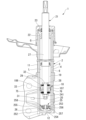
- 1 is a cross-sectional view showing a shock absorber according to an embodiment of the present invention.
- 1 is a cross-sectional view of a main portion of a shock absorber according to an embodiment of the present invention.
- 1 is a partial cross-sectional view showing a main portion of a shock absorber according to an embodiment of the present invention.
- 1 is a partial cross-sectional view showing a main portion of a shock absorber according to an embodiment of the present invention.
- 1 is a partial cross-sectional view showing a main portion of a shock absorber according to an embodiment of the present invention.
- shock absorber according to one embodiment of the present invention will be described with reference to the drawings.
- the upper side of the drawings will be referred to as “upper” and the lower side of the drawings will be referred to as “lower”.
- the shock absorber 1 of the embodiment is a twin-tube hydraulic shock absorber.
- the shock absorber 1 is used in a suspension device for a vehicle, specifically an automobile.
- the shock absorber 1 is equipped with a cylinder 2.
- the cylinder 2 has an inner tube 3 and an outer tube 4.
- the inner tube 3 is cylindrical.
- the outer tube 4 is cylindrical with a bottom.
- the inner diameter of the outer tube 4 is larger than the outer diameter of the inner tube 3.
- the inner tube 3 is disposed radially inside the outer tube 4.
- the central axis of the inner tube 3 and the central axis of the outer tube 4 coincide.
- a reservoir chamber 6 is formed between the inner tube 3 and the outer tube 4.
- the outer cylinder 4 has a body 11 and a bottom 12.
- the body 11 and the bottom 12 are formed seamlessly as a single unit.
- the body 11 is cylindrical.
- the bottom 12 closes the lower part of the body 11.
- the shock absorber 1 is equipped with a piston 18.
- the piston 18 is inserted into the inner tube 3 of the cylinder 2.
- the piston 18 is fitted slidably inside the inner tube 3 of the cylinder 2.
- the piston 18 divides the inner tube 3 into two chambers, a first chamber 19 on one side and a second chamber 20 on the other side.
- the first chamber 19 is located on the opposite side of the piston 18 from the bottom 12.
- the second chamber 20 is located on the bottom 12 side from the piston 18.
- oil L is sealed in the first chamber 19 and the second chamber 20 in the inner tube 3 as a working fluid.
- oil L and gas G are sealed in the reservoir chamber 6 between the inner tube 3 and the outer tube 4 as a working fluid.
- the shock absorber 1 is equipped with a piston rod 21.
- One axial end of the piston rod 21 is disposed within the inner tube 3 of the cylinder 2. This one end of the piston rod 21 is connected to the piston 18. The other axial end of the piston rod 21 extends from the cylinder 2 to the outside of the cylinder 2.
- the piston 18 is fixed to the piston rod 21. Therefore, the piston 18 and the piston rod 21 move together.
- the stroke in which the piston rod 21 moves in a direction to increase the amount of protrusion from the cylinder 2 is the extension stroke in which the overall length increases.
- the stroke in which the piston rod 21 moves in a direction to decrease the amount of protrusion from the cylinder 2 is the compression stroke in which the overall length contracts.
- the piston 18 moves towards the first chamber 19 during the extension stroke.
- the piston 18 moves towards the second chamber 20 during the compression stroke.
- a rod guide 22 is fitted to the upper opening side of the inner cylinder 3 and the upper opening side of the outer cylinder 4.
- a seal member 23 is fitted to the outer cylinder 4 above the rod guide 22. Both the rod guide 22 and the seal member 23 are annular.
- the piston rod 21 is inserted into the radial inside of each of the rod guide 22 and the seal member 23.
- the piston rod 21 slides along the axial direction of each of the rod guide 22 and the seal member 23.
- the piston rod 21 extends from the inside of the cylinder 2 to the outside of the cylinder 2 beyond the seal member 23.
- the rod guide 22 restricts the piston rod 21 from moving radially relative to the inner tube 3 and outer tube 4 of the cylinder 2.
- the piston 18 fits into the inner tube 3.
- the rod guide 22 supports the piston rod 21 so that it can move in the axial direction of the piston rod 21.
- the outer periphery of the seal member 23 is in close contact with the outer tube 4.
- the inner periphery of the seal member 23 is in close contact with the outer periphery of the piston rod 21.
- the piston rod 21 moves in the axial direction of the seal member 23 relative to the seal member 23.
- the seal member 23 prevents the oil liquid L in the inner tube 3 and the high-pressure gas G and oil liquid L in the reservoir chamber 6 from leaking out to the outside.
- the outer periphery of the rod guide 22 is larger in diameter at the top than at the bottom.
- the smaller-diameter lower part of the rod guide 22 fits into the inner periphery of the upper end of the inner cylinder 3.
- the larger-diameter upper part of the rod guide 22 fits into the inner periphery of the upper part of the outer cylinder 4.
- a base member 26 of a base valve 25 is installed on the bottom 12 of the outer cylinder 4.
- the base member 26 is positioned radially relative to the outer cylinder 4.
- the outer periphery of the base member 26 is smaller in diameter at the top than at the bottom.
- the smaller-diameter upper part of the base member 26 fits into the inner periphery of the lower end of the inner cylinder 3. This causes the central axis of the inner cylinder 3 to coincide with the central axis of the outer cylinder 4.
- the base member 26 separates the second chamber 20 from the reservoir chamber 6.
- the upper end of the outer tube 4 is crimped radially inward of the outer tube 4.
- the seal member 23 is fixed to the cylinder 2 by being sandwiched between this crimped portion and the rod guide 22.
- the piston rod 21 has a main shaft portion 27 and a mounting shaft portion 28. Both the main shaft portion 27 and the mounting shaft portion 28 are rod-shaped.
- the outer diameter of the mounting shaft portion 28 is smaller than the outer diameter of the main shaft portion 27.
- the mounting shaft portion 28 is disposed in the cylinder 2.
- the piston 18 is attached to the mounting shaft portion 28.
- the main shaft portion 27 has a shaft step portion 29.
- the shaft step portion 29 is provided at the end of the main shaft portion 27 on the mounting shaft portion 28 side in the axial direction.
- the shaft step portion 29 spreads in a direction perpendicular to the central axis of the piston rod 21.
- the end of the mounting shaft portion 28 opposite the main shaft portion 27 in the axial direction of the mounting shaft portion 28 is a threaded shaft portion 31.
- the threaded shaft portion 31 is formed with a male thread on the outer periphery.
- the portion of the mounting shaft portion 28 between the main shaft portion 27 and the threaded shaft portion 31 in the axial direction of the mounting shaft portion 28 is a mating shaft portion 32.
- the outer periphery of the mating shaft portion 32 is a cylindrical surface.
- the piston 18 is mated with the mating shaft portion 32.
- the shock absorber 1 is connected to the vehicle body with the portion of the piston rod 21 protruding from the cylinder 2 located at the top. At the same time, the shock absorber 1 is connected to the wheel side of the vehicle with the mounting bracket 33 fixed to the body 11 of the outer tube 4 located at the bottom.
- the shock absorber 1 may be a monotube type instead of a double tube type.
- the monotube type has a structure in which the outer tube 4 and base valve 25 are eliminated from the shock absorber 1, a bottomed cylindrical cylinder is provided instead of the inner tube 3, and a free piston is provided between the bottom of the cylinder and the piston 18. Gas is sealed between the bottom of the cylinder and the free piston. With such a monotube shock absorber, it is also possible to connect the cylinder side to the vehicle body and the piston rod 21 to the wheel side.
- the piston 18 has a first piston body 36, a second piston body 37, and a piston band 38.
- the first piston body 36 and the second piston body 37 are both integrally molded metal products.
- the first piston body 36 and the second piston body 37 are both annular.
- the first piston body 36 and the second piston body 37 of the piston 18 are connected to the mounting shaft portion 28 of the piston rod 21.
- the first piston body 36 is disposed on the opposite side of the main shaft portion 27 than the second piston body 37 in the axial direction of the piston rod 21.
- the second piston body 37 is disposed between the first piston body 36 and the shaft step portion 29.
- the first piston body 36 has a joint surface 41 formed on the axial side facing the second piston body 37.
- the joint surface 41 is flat and extends perpendicular to the central axis of the first piston body 36.
- the first piston body 36 has a through hole 42 formed in its radial center.
- the through hole 42 passes through the first piston body 36 in the axial direction of the first piston body 36.
- the mounting shaft portion 28 of the piston rod 21 is fitted into the through hole 42 of the first piston body 36.
- the first piston body 36 has a main body portion 43, an inner seat 45, a first seat 46, and a second seat 47.
- the main body portion 43 is annular. The radial inner side of the main body portion 43 forms part of the through hole 42.
- the inner sheet 45 is annular.
- the inner sheet 45 protrudes from the main body 43 on the opposite side to the joining surface 41 in the axial direction of the first piston body 36.
- the inner radial side of the inner sheet 45 forms part of the through hole 42.
- the first seat 46 is annular.
- the first seat 46 protrudes from the main body 43 on the opposite side to the joint surface 41 in the axial direction of the first piston body 36.
- the first seat 46 has a larger diameter than the inner seat 45.
- the first seat 46 is disposed outside the inner seat 45 in the radial direction of the first piston body 36 so as to surround the inner seat 45.
- the tip surface of the first seat 46 is disposed on the opposite side to the joint surface 41 than the tip surface of the inner seat 45 in the axial direction of the first piston body 36.
- the first piston body 36 has a passage groove 51 formed between the inner sheet 45 and the first sheet 46 in the radial direction of the first piston body 36.
- the passage groove 51 is annular and extends in the circumferential direction of the first piston body 36.
- a passage hole 52 is formed in the main body 43 of the first piston body 36 between the inner sheet 45 and the first sheet 46 in the radial direction of the first piston body 36.
- the passage hole 52 is disposed closer to the first sheet 46 than the inner sheet 45 in the radial direction of the first piston body 36.
- One end of the passage hole 52 opens to the joint surface 41, and the other end opens to the passage groove 51.
- the first piston body 36 has multiple passage holes 52 of the same shape provided at equal intervals in the circumferential direction of the first piston body 36.
- the second seat 47 is annular.
- the second seat 47 protrudes from the main body 43 on the side opposite the joining surface 41 in the axial direction of the first piston body 36.
- the second seat 47 has a larger diameter than the first seat 46.
- the second seat 47 is disposed outside the first seat 46 in the radial direction of the first piston body 36 so as to surround the first seat 46.
- the second seat 47 is disposed on the side opposite the joining surface 41 from the first seat 46 in the axial direction of the first piston body 36.
- the first piston body 36 has an outer peripheral surface 61 formed at its radially outer end.
- the outer peripheral surface 61 is a cylindrical surface centered on the central axis of the first piston body 36.
- the outer peripheral surface 61 is provided on the main body portion 43.
- the first piston body 36 has an opening groove 62 on its radially outer outer periphery.
- the opening groove 62 is recessed radially inward of the first piston body 36 relative to the outer periphery 61.
- the opening groove 62 is annular about the central axis of the first piston body 36.
- the opening groove 62 is provided between the center of the first piston body 36 in the axial direction and the second seat 47. The bottom surface of the opening groove 62 overlaps with the second seat 47 in the radial direction of the first piston body 36.
- a passage hole 65 is formed in the main body 43 of the first piston body 36.
- One end of the passage hole 65 opens to the joint surface 41, and the other end opens to the opening groove portion 62.
- the first piston body 36 has a plurality of passage holes 65 of the same shape, equally spaced in the circumferential direction of the first piston body 36.
- the first piston body 36 has passage holes 52 and passage holes 65 alternately arranged at an equal pitch in the circumferential direction of the first piston body 36.
- the first piston body 36 has the same number of passage holes 52 and passage holes 65.
- the main body 43 has a recessed portion 72 that is recessed from the joint surface 41 toward the inner sheet 45 in the axial direction of the first piston body 36.
- the passages in the multiple passage holes 52 and the passage in the passage groove 51 form a first passage 75.
- the first passage 75 includes the space between the inner sheet 45 and the first sheet 46. Therefore, the first sheet 46 communicates with the first passage 75.
- the first passage 75 includes the space between the first sheet 46 and the second sheet 47. Therefore, the second sheet 47 also communicates with the first passage 75.
- the passages in the multiple passage holes 65 and the passage in the open groove portion 62 form a second passage 76.
- the second piston body 37 has a joint surface 81 formed on the axial side facing the first piston body 36.
- the joint surface 81 is flat and extends perpendicular to the central axis of the second piston body 37.
- a through hole 82 is formed in the radial center of the second piston body 37.
- the through hole 82 passes through the second piston body 37 in the axial direction of the second piston body 37.
- the mounting shaft portion 28 of the piston rod 21 is fitted into the through hole 82 of the second piston body 37.
- the second piston body 37 has a main body portion 83, an inner sheet 85, a third sheet 86, a fourth sheet 87, and a convex portion 89.
- the main body portion 83 is annular. The radial inner side of the main body portion 83 forms part of the through hole 82.
- the inner sheet 85 is annular.
- the inner sheet 85 protrudes from the main body 83 on the opposite side to the joining surface 81 in the axial direction of the second piston body 37.
- the inner radial side of the inner sheet 85 forms part of the through hole 82.
- the third seat 86 is annular.
- the third seat 86 protrudes from the main body 83 on the opposite side to the joining surface 81 in the axial direction of the second piston body 37.
- the third seat 86 has a larger diameter than the inner seat 85.
- the third seat 86 is disposed outside the inner seat 85 in the radial direction of the second piston body 37 so as to surround the inner seat 85.
- the tip surface of the third seat 86 is disposed on the opposite side to the joining surface 81 than the tip surface of the inner seat 85 in the axial direction of the second piston body 37.
- the second piston body 37 has a passage groove 91 formed between the inner sheet 85 and the third sheet 86 in the radial direction of the second piston body 37.
- the passage groove 91 is annular and extends in the circumferential direction of the second piston body 37.
- a passage hole 92 is formed in the main body 83 of the second piston body 37 between the inner sheet 85 and the third sheet 86 in the radial direction of the second piston body 37.
- the passage hole 92 is disposed closer to the third sheet 86 than the inner sheet 85 in the radial direction of the second piston body 37.
- One end of the passage hole 92 opens to the joint surface 81, and the other end opens to the passage groove 91.
- the second piston body 37 has a plurality of passage holes 92 of the same shape provided at equal intervals in the circumferential direction of the second piston body 37.
- the number of passage holes 92 is the same as the number of passage holes 52 of the first piston body 36.
- the fourth seat 87 is annular.
- the fourth seat 87 protrudes from the main body 83 on the opposite side of the joining surface 81 in the axial direction of the second piston body 37.
- the fourth seat 87 has a larger diameter than the third seat 86.
- the fourth seat 87 is disposed outside the third seat 86 in the radial direction of the second piston body 37 so as to surround the third seat 86.
- the fourth seat 87 is disposed on the opposite side of the joining surface 81 from the third seat 86 in the axial direction of the second piston body 37.
- the second piston body 37 has an outer peripheral surface 101 formed at its radially outer end.
- the outer peripheral surface 101 is a cylindrical surface centered on the central axis of the second piston body 37.
- the outer peripheral surface 101 is provided on the main body portion 83.
- the outer diameter of the outer peripheral surface 101 i.e., the outer diameter of the second piston body 37, is equal to the outer diameter of the outer peripheral surface 61 of the first piston body 36, i.e., the outer diameter of the first piston body 36.
- the second piston body 37 has an open groove portion 102 on its outer periphery on the radially outer side.
- the open groove portion 102 is recessed radially inward of the second piston body 37 relative to the outer periphery 101.
- the open groove portion 102 is annular about the central axis of the second piston body 37.
- the open groove portion 102 is provided between the center of the second piston body 37 in the axial direction and the fourth seat 87.
- the bottom surface of the open groove portion 102 overlaps with the fourth seat 87 in the radial direction of the second piston body 37.
- a passage hole 105 is formed in the main body 83 of the second piston body 37.
- One end of the passage hole 105 opens to the joint surface 81, and the other end opens to the opening groove portion 102.
- the second piston body 37 has a plurality of passage holes 105 of the same shape, equally spaced in the circumferential direction of the second piston body 37.
- the second piston body 37 has passage holes 92 and passage holes 105 alternately arranged at equal pitches in the circumferential direction of the second piston body 37.
- the second piston body 37 has the same number of passage holes 92 and passage holes 105.
- the number of passage holes 105 is the same as the number of passage holes 65 of the first piston body 36.
- the convex portion 89 protrudes from the joint surface 81 on the opposite side to the inner sheet 85 in the axial direction of the second piston body 37.
- the passages in the multiple passage holes 105 and the passage in the open groove portion 102 form a third passage 106.
- the passages in the multiple passage holes 92 and the passage in the passage groove 91 form a fourth passage 107.
- the fourth passage 107 includes the space between the inner seat 85 and the third seat 86. Therefore, the third seat 86 communicates with the fourth passage 107.
- the fourth passage 107 includes the space between the third seat 86 and the fourth seat 87. Therefore, the fourth seat 87 also communicates with the fourth passage 107.
- the first sheet 46 and the third sheet 86 have the same shape.
- the second sheet 47 and the fourth sheet 87 have the same shape.
- the passage groove 51 and the passage groove 91 have the same shape.
- the passage hole 52 and the passage hole 92 have the same shape.
- the opening groove portion 62 and the opening groove portion 102 have the same shape.
- the passage hole 65 and the passage hole 105 have the same shape.
- the first piston body 36 and the second piston body 37 are arranged such that the convex portion 89 of the second piston body 37 fits into the concave portion 72 of the first piston body 36.
- the mating surface 41 of the first piston body 36 and the mating surface 81 of the second piston body 37 are in surface contact.
- the central axis of the first piston body 36 and the central axis of the second piston body 37 coincide with each other.
- the passage hole 52 of the first piston body 36 overlaps with the passage hole 105 of the second piston body 37 in the circumferential and radial directions of the first piston body 36 and the second piston body 37.
- the passage hole 52 of the first piston body 36 does not overlap with the passage hole 92 in the circumferential and radial directions of the first piston body 36 and the second piston body 37.
- the first passage 75 of the first piston body 36 communicates with the third passage 106 of the second piston body 37, but does not communicate with the fourth passage 107.
- the passage hole 65 of the first piston body 36 overlaps with the passage hole 92 of the second piston body 37 in the circumferential and radial directions of the first piston body 36 and the second piston body 37.
- the passage hole 65 of the first piston body 36 does not overlap with the passage hole 105 in the circumferential and radial directions of the first piston body 36 and the second piston body 37.
- the second passage 76 of the first piston body 36 communicates with the fourth passage 107 of the second piston body 37, but does not communicate with the third passage 106.
- first piston body 36 and the second piston body 37 are aligned when the convex portion 89 fits into the concave portion 72.
- the first piston body 36 and the second piston body 37 are not aligned in any other connection state. In other words, in any other state, the first piston body 36 and the second piston body 37 are not in a state in which the first passage 75 and the third passage 106 are connected, the second passage 76 and the fourth passage 107 are connected, and the mating surface 41 and the mating surface 81 are not in surface contact, as described above.
- the convex portion 89 and the concave portion 72 form the alignment portion 121.
- the alignment portion 121 is provided on the joint surfaces 41, 81 where the first piston body 36 and the second piston body 37 are connected to each other.
- the alignment portion 121 aligns the positions of the first passage 75 and the third passage 106, and also aligns the positions of the second passage 76 and the fourth passage 107 in the circumferential and radial directions of the first piston body 36 and the second piston body 37.
- the first piston body 36 and the second piston body 37 are fixed together and integrated by pressing the convex portion 89 into the concave portion 72. At that time, the first piston body 36 and the second piston body 37 are positioned circumferentially and radially by the alignment portion 121, and the first passage 75 and the third passage 106 are communicated, the second passage 76 and the fourth passage 107 are communicated, and the joint surface 41 and the joint surface 81 are in surface contact. In other words, the first piston body 36 and the second piston body 37 are connected so that the first passage 75 and the third passage 106 are communicated, and the second passage 76 and the fourth passage 107 are communicated.
- the first piston body 36 is formed by cutting the inner sheet 45, the first sheet 46, and the second sheet 47 while being integrated with the second piston body 37.
- the end of the first piston body 36 opposite the third passage 106 of the first passage 75 is formed by cutting.
- the inner sheet 85, the third sheet 86, and the fourth sheet 87 are formed by cutting.
- the end of the fourth passage 107 opposite the second passage 76 of the second piston body 37 is formed by cutting.
- the first sheet 46 and the third sheet 86 become mirror images. Also, after these processes, the second sheet 47 and the fourth sheet 87 become mirror images. Also, after these processes, the difference in height between the inner sheet 45 and the first sheet 46 becomes greater by a predetermined amount than the difference in height between the inner sheet 85 and the third sheet 86.
- the first piston body 36 and the second piston body 37 are cut at the same time at their outer peripheries while being integrated together.
- the opening groove 62 of the first piston body 36 is formed, and the opening groove 102 of the second piston body 37 is formed.
- the end of the first piston body 36 opposite the fourth passage 107 of the second passage 76 is formed by cutting.
- the end of the second piston body 37 opposite the first passage 75 of the third passage 106 is formed by cutting.
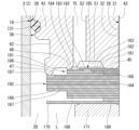
- the deep groove 131 (groove) shown in FIG. 3 is formed on the outer periphery of the first piston body 36 by cutting.
- the outer periphery of the first piston body 36 and the outer periphery of the second piston body 37 are formed with the outer periphery surfaces 61, 101 and a plurality (specifically, four locations) of shallow grooves 132 (grooves) by cutting.
- the outer periphery surfaces 61, 101 are formed to form the same cylindrical surface.
- the deep groove portion 131 is recessed radially inward of the first piston body 36 relative to the outer circumferential surface 101.
- the deep groove portion 131 is annular about the central axis of the first piston body 36.
- the deep groove portion 131 is formed in a portion of the first piston body 36 closer to the second piston body 37 than the open groove portion 62 in the axial direction.
- the shallow groove portions 132 are of the same shape and are recessed radially inward of the first piston body 36 and the second piston body 37 relative to the outer circumferential surfaces 61, 101.
- the shallow groove portions 132 are all annular about the central axis of the first piston body 36 and the second piston body 37.
- the shallow groove portions 132 are shallower in depth from the outer circumferential surfaces 61, 101 than the deep groove portion 131 is from the outer circumferential surfaces 61, 101.
- the deep groove portion 131 is deeper from the outer circumferential surfaces 61, 101 than the shallow groove portions 132 are from the outer circumferential surfaces 61, 101.
- the diameter of the bottom of the deep groove portion 131 is smaller than the diameter of the bottom of the shallow groove portions 132.
- the shallow groove portions 132 are formed in a portion of the first piston body 36 closer to the second piston body 37 than the deep groove portion 131 in the axial direction, and in a portion of the second piston body 37 closer to the first piston body 36 than the open groove portion 102.
- the deep groove portion 131 is located closer to the second seat 47 shown in FIG. 4 in the axial direction of the first piston body 36 and the second piston body 37 than the shallow groove portions 132.
- the shallow groove portions 132 are arranged in a line at equal intervals in the axial direction of the first piston body 36 and the second piston body 37.
- the piston band 38 is made of synthetic resin and is formed in an endless band shape.
- the piston band 38 has a base portion 141, a deep groove fitting portion 142, and multiple (specifically, four) shallow groove fitting portions 143.
- the base portion 141 is an endless strip of constant thickness.
- the deep groove fitting portion 142 protrudes radially inward from the cylindrical inner peripheral surface 151 of the base portion 141.
- the deep groove fitting portion 142 is provided at one end of the base portion 141 in the axial direction.
- the deep groove fitting portion 142 is an endless ring shape that continues around the entire circumference of the base portion 141.
- the shallow groove fittings 143 are of the same shape and protrude from the inner circumferential surface 151 of the base portion 141 inward in the radial direction of the base portion 141.
- the shallow groove fittings 143 are provided at intermediate positions in the axial direction of the base portion 141.
- the shallow groove fittings 143 are all endless annular shapes that are continuous around the entire circumference of the base portion 141.
- the shallow groove fittings 143 are arranged at equal intervals in the axial direction of the base portion 141.
- the shallow groove fittings 143 protrude from the inner circumferential surface 151 of the base portion 141 to a height that is lower than the protruding height of the deep groove fittings 142 from the inner circumferential surface 151.
- the piston band 38 has an inner diameter of the shallow groove fittings 143 that is larger than the inner diameter of the deep groove fittings 142.
- the piston band 38 is attached so as to cover the outer periphery of the first piston body 36 and the second piston body 37 integrated by press-fitting as described above.
- the piston band 38 is elastically deformed so as to expand in diameter, and is placed on the first piston body 36 and the second piston body 37 shown in FIG. 3 from the second seat 47 side shown in FIG. 4, with the side opposite the deep groove fitting portion 142 in the axial direction leading.
- the deep groove fitting portion 142 of the piston band 38 is first released from the expansion diameter and fitted into the deep groove portion 131 of the first piston body 36, and then each of the multiple shallow groove fitting portions 143 is released from the expansion diameter and fitted into the corresponding one of the multiple shallow groove portions 132.
- the inner periphery 151 of the base portion 141 comes into surface contact with the outer periphery surfaces 61, 101 of the first piston body 36 and the second piston body 37 in close contact.
- the piston band 38 is attached integrally to the outer circumferential surfaces 61, 101 of the first piston body 36 and the second piston body 37 to form the piston 18.
- the piston 18 is composed of only three parts: the first piston body 36, the second piston body 37, and the piston band 38.
- the piston 18 is formed by including a first step, a second step, and a third step.
- the first step is a step of connecting the joint surface 41, which is one surface of the first piston body 36, to the joint surface 81, which is one surface of the second piston body 37, so that the first passage 75 and the third passage 106 communicate with each other, and the second passage 76 and the fourth passage 107 communicate with each other, as shown in FIG. 2.
- the second step is a step of machining the end of the first passage 75 opposite the third passage 106, the end of the third passage 106 opposite the first passage 75, the end of the second passage 76 opposite the fourth passage 107, the end of the fourth passage 107 opposite the second passage 76, and the deep groove portion 131 and the plurality of shallow groove portions 132 to which the piston band 38 is attached, as shown in FIG. 3.
- the third step is a step of attaching the piston band 38 to the deep groove portion 131 and the plurality of shallow groove portions 132. In the third step, the piston band 38 is attached to the deep groove portion 131 via the second sheet 47 shown in FIG. 2, and then attached to the shallow groove portions 132.
- the piston 18 is fitted to the fitting shaft portion 32 of the piston rod 21 such that the second piston body 37 is disposed between the first piston body 36 and the shaft step portion 29 in the axial direction of the piston rod 21. At that time, the piston 18 is positioned radially relative to the piston rod 21 by fitting the through hole 82 of the second piston body 37 and the through hole 42 of the first piston body 36 into the fitting shaft portion 32.
- the first seat 46 and the second seat 47 of the first piston body 36 are disposed on the second chamber 20 side, and the third seat 86 and the fourth seat 87 of the second piston body 37 are disposed on the first chamber 19 side.
- the piston 18 slides relative to the inner cylinder 3 with the piston band 38 in contact with the inner surface of the inner cylinder 3 on its outer surface.
- one disk 161, one disk 162, one disk 163, one disk 164, one disk 165, one disk 166, multiple disks 167 (specifically, six disks), multiple disks 168 (specifically, three disks), one disk 169, one disk 170, and one annular member 171 are stacked.
- the number of disks shown here is one embodiment, and can be adjusted as appropriate according to the desired damping force characteristics.
- the disks 161-170 and the ring member 171 are all made of metal.
- the disks 161-170 are all circular flat plates with holes of a fixed thickness.
- the ring member 171 is annular.
- the fitting shaft portion 32 of the piston rod 21 is fitted inside the disks 161-170 and the ring member 171.
- the outer diameter of the disk 161 is larger than the outer diameter of the inner seat 45 of the piston 18 and smaller than the inner diameter of the first seat 46.
- the outer diameter of the disk 162 is larger than the outer diameter of the first seat 46 of the piston 18 and smaller than the inner diameter of the second seat 47.
- the disk 162 moves away from and into contact with the first seat 46 to open and close the first passage 75 at the position of the first seat 46.
- a passage hole 182 is formed in the disk 162 at a position between the inner seat 45 of the piston 18 and the outer periphery of the disk 161.
- the passage hole 182 penetrates the disk 162 in the axial direction of the disk 162.
- the passage hole 182 is an arc-shaped long hole extending in the circumferential direction of the disk 162.
- the passage hole 182 is opened and closed by the disk 161.
- the outer diameter of disk 163 is equal to the outer diameter of disk 162.
- Disk 163 has a notch 183 formed on its outer periphery. Notch 183 penetrates disk 163 in the axial direction of disk 163. Notch 183 opens to the outer periphery of disk 163.
- Disk 163 has a plurality of notches 183 formed at equal intervals in the circumferential direction of disk 163. The radially inner portions of the plurality of notches 183 communicate with passage hole 182 of disk 162.
- the plurality of notches 183 and passage hole 182 form a fixed orifice 184. Fixed orifice 184 is opened and closed by disk 161.
- Disks 161 and 162 form a check valve 185.
- the check valve 185 allows the flow of oil L from the fixed orifice 184 to the passage in the passage groove 51, and restricts the flow of oil L from the passage in the passage groove 51 to the fixed orifice 184.
- the outer diameter of disk 164 is equal to the outer diameter of disk 163.
- Disk 164 covers the multiple cutouts 183 of disk 163 on the side opposite disk 162 to form a fixed orifice 184.
- the fixed orifice 184 and the check valve 185 which allows the flow of oil liquid L through the fixed orifice 184 in only one direction, are composed of multiple stacked disks 161-164.
- the outer diameter of disk 165 is smaller than the outer diameter of disk 164 and slightly larger than the outer diameter of inner sheet 45.
- the outer diameter of the disk 166 is equal to the outer diameter of the second seat 47 of the piston 18.
- the disk 166 separates from and contacts the second seat 47 to open and close the first passage 75 at the position of the second seat 47.
- the disk 166 has a notch 186 formed on its outer periphery.
- the notch 186 penetrates the disk 166 in the axial direction of the disk 166.
- the notch 186 opens to the outer periphery of the disk 166.
- the disk 166 has a plurality of notches 186 formed at equal intervals in the circumferential direction of the disk 166.
- the plurality of notches 186 extend so as to cross the second seat 47 in the radial direction.
- the plurality of notches 186 form a fixed orifice 187 in the first passage 75 when the disk 166 contacts the second seat 47.
- the flow passage cross-sectional area of the fixed orifice 187 is larger than the flow passage cross-sectional area of the fixed orifice 184.
- the multiple disks 167 have the same outer diameter, and each outer diameter is equal to the outer diameter of disk 166. Of the multiple disks 167, the disk 167 closest to disk 166 covers the multiple cutouts 186 of disk 166 on the side opposite to second sheet 47 to form a fixed orifice 187.
- the multiple disks 168 have the same outer diameter, and each outer diameter is smaller than the outer diameter of disk 167 and larger than the outer diameter of disk 165.
- the outer diameter of disk 169 is smaller than the outer diameter of disk 168 and is equal to the outer diameter of disk 165.
- the outer diameter of disk 170 is larger than the outer diameter of disk 169 and is equal to the outer diameter of disk 167.
- the outer diameter of the ring member 171 is smaller than the outer diameter of the disk 170 and larger than the outer diameter of the disk 169.
- the thickness of the ring member 171 is greater than the thickness of each of the disks 161 to 170, and the ring member 171 has higher rigidity than the disks 161 to 170.
- the first passage 75 and the third passage 106 shown in FIG. 2 are flow paths through which oil L flows from the first chamber 19 to the second chamber 20 during the extension stroke.
- the third passage 106 is constantly connected to the first chamber 19.
- the disks 162-164 are placed on the first seat 46 and constitute a first damping valve 191 that opens and closes the first passage 75 by moving away from and into contact with the first seat 46.
- the first damping valve 191 is provided with a fixed orifice 184 and a check valve 185.
- the discs 166-168 constitute a second damping valve 192 that is placed on the second seat 47 and opens and closes the first passage 75 by moving away from and into contact with the second seat 47.
- a fixed orifice 187 is provided in the second damping valve 192.
- the second damping valve 192 is provided closer to the second chamber 20 than the first damping valve 191.
- the second damping valve 192 has a total thickness of the discs 166-168 that is greater than the total thickness of the discs 162-164 of the first damping valve 191.
- the second damping valve 192 has a higher rigidity than the first damping valve 191.
- the first damping valve 191 When the first damping valve 191 leaves the first seat 46 and opens, it allows oil L to flow from the first chamber 19 shown in FIG. 2 to the second chamber 20 via the third passage 106, the passages in the multiple passage holes 52, the passages in the passage groove 51, and the passage between the first damping valve 191 and the first seat 46, all of which constitute the first passage 75. At that time, the first damping valve 191 suppresses the flow of oil L to generate a damping force.
- the first damping valve 191 is provided in the first passage 75, and suppresses the flow of oil L that occurs during the extension stroke to generate a damping force.
- the second damping valve 192 is more rigid than the first damping valve 191, and therefore after the first damping valve 191 leaves the first seat 46 and opens, it leaves the second seat 47 and opens.
- the second damping valve 192 leaves the second seat 47 and opens, it flows oil L from the first chamber 19 to the second chamber 20 side through the third passage 106, the passages in the passage holes 52, the passages in the passage groove 51, the passage between the first damping valve 191 and the first seat 46, the passage between the first seat 46 and the second seat 47, and the passage between the second damping valve 192 and the second seat 47, all of which constitute the first passage 75.
- the second damping valve 192 generates a damping force by suppressing the flow of oil L.
- the second damping valve 192 is provided in the first passage 75 and generates a damping force by suppressing the flow of oil L that occurs during the extension stroke.
- the first damping valve 191 is provided upstream of the second damping valve 192 in the flow direction of the oil L during the extension stroke.
- the first damping valve 191 has lower rigidity and a lower opening pressure than the second damping valve 192. Therefore, the first damping valve 191 opens in a region where the moving speed of the piston 18 (hereinafter referred to as the piston speed) is lower than that of the second damping valve 192.
- the first piston body 36 has a first seat 46 and a second seat 47.
- the first seat 46 communicates with the first passage 75, and a first damping valve 191 that opens at a low piston speed is mounted on it.
- the second seat 47 has a larger diameter than the first seat 46 and is located closer to the second chamber 20 than the first seat 46, and a second damping valve 192 that opens after the first damping valve 191 opens is mounted on it.
- the check valve 185 provided in the first damping valve 191 closes against the flow from the first chamber 19 toward the second chamber 20 that occurs during the extension stroke.
- the inner seat 85 of the piston 18 is stacked with, in order from the inner seat 85 side in the axial direction of the piston 18, one disk 201, multiple disks (specifically, two) 202, one disk 203, one disk 204, multiple disks (specifically, three) 205, multiple disks (specifically, two) 206, one disk 207, one disk 208, and one ring member 209.
- the number of disks shown here is one embodiment, and can be adjusted as appropriate according to the desired damping force characteristics.
- the disks 201-208 and the ring member 209 are all made of metal.
- the disks 201-208 are all circular flat plates with holes of a fixed thickness.
- the ring member 209 is annular.
- the fitting shaft portion 32 of the piston rod 21 fits into the inside of the disks 201-208 and the ring member 209.
- the outer diameter of the disk 201 is larger than the outer diameter of the third seat 86 of the piston 18 and smaller than the inner diameter of the fourth seat 87.
- the disk 201 separates from and contacts the third seat 86 to open and close the fourth passage 107 at the position of the third seat 86.
- the disk 201 has a notch 221 formed on its outer periphery.
- the notch 221 penetrates the disk 201 in the axial direction of the disk 201.
- the notch 221 opens to the outer periphery of the disk 201.
- the disk 201 has a plurality of notches 221 formed at equal intervals in the circumferential direction of the disk 201.
- the plurality of notches 221 extend radially across the third seat 86.
- the plurality of notches 221 form a fixed orifice 222 in the fourth passage 107 when the disk 201 is in contact with the third seat 86.
- the multiple disks 202 have the same outer diameter, and each outer diameter is equal to the outer diameter of disk 201.
- the disk 202 closest to disk 201 covers the multiple cutouts 221 of disk 201 on the side opposite to third sheet 86 to form a fixed orifice 222.
- the outer diameter of disk 203 is smaller than the outer diameter of disk 202 and slightly larger than the outer diameter of inner sheet 85.
- the outer diameter of the disk 204 is larger than the outer diameter of the fourth seat 87 of the piston 18.
- the disk 204 moves away from and abuts against the fourth seat 87 to open and close the fourth passage 107 at the position of the fourth seat 87.
- a notch 225 is formed in the outer periphery of the disk 204.
- the notch 225 penetrates the disk 204 in the axial direction of the disk 204.
- the notch 225 opens to the outer periphery of the disk 204.
- a plurality of notches 225 are formed in the disk 204 at equal intervals in the circumferential direction of the disk 204.
- the plurality of notches 225 extend radially across the fourth seat 87.
- the plurality of notches 225 form a fixed orifice 226 in the fourth passage 107 when the disk 204 abuts against the fourth seat 87.
- the cross-sectional area of the fixed orifice 226 is larger than the cross-sectional area of the fixed orifice 222.
- the multiple disks 205 have the same outer diameter, and each outer diameter is equal to the outer diameter of disk 204.
- the disk 205 closest to disk 204 covers the multiple cutouts 225 of disk 204 on the side opposite to the fourth sheet 87 to form a fixed orifice 226.
- the multiple disks 206 have the same outer diameter, and each outer diameter is smaller than the outer diameter of disk 205 and larger than the outer diameter of disk 203.
- the outer diameter of disk 207 is smaller than the outer diameter of disk 206 and is equal to the outer diameter of disk 203.
- the outer diameter of disk 208 is larger than the outer diameter of disk 207 and is equal to the outer diameter of disk 205.
- the outer diameter of the ring member 209 is smaller than the outer diameter of the disk 208 and larger than the outer diameter of the disk 207.
- the thickness of the ring member 209 is greater than the thickness of each of the disks 201 to 208, and the ring member 209 has higher rigidity than the disks 201 to 208.
- the fourth passage 107 and the second passage 76 are flow paths through which oil L flows from the second chamber 20 to the first chamber 19 mainly during the compression stroke.
- the second passage 76 is constantly connected to the second chamber 20.
- the disks 201 and 202 shown in FIG. 5 are placed on the third seat 86 and constitute a third damping valve 231 that opens and closes the fourth passage 107 by moving away from and into contact with the third seat 86.
- a fixed orifice 222 is provided in the third damping valve 231.
- the discs 204-206 are placed on the fourth seat 87 and constitute a fourth damping valve 232 that opens and closes the fourth passage 107 by moving away from and into contact with the fourth seat 87.
- a fixed orifice 226 is provided in the fourth damping valve 232.
- the fourth damping valve 232 is provided closer to the first chamber 19 than the third damping valve 231.
- the total thickness of the discs 204-206 of the fourth damping valve 232 is thicker than the total thickness of the discs 201, 202 of the third damping valve 231, and the fourth damping valve 232 has higher rigidity than the third damping valve 231.
- the third damping valve 231 When the third damping valve 231 leaves the third seat 86 and opens, it allows oil L to flow from the second chamber 20 shown in FIG. 2 to the first chamber 19 side via the second passage 76, the passages in the multiple passage holes 92, the passages in the passage groove 91, and the passage between the third damping valve 231 and the third seat 86, all of which constitute the fourth passage 107. At that time, the third damping valve 231 suppresses the flow of oil L to generate a damping force.
- the third damping valve 231 is provided in the fourth passage 107, and generates a damping force by suppressing the flow of oil L that occurs during the compression stroke.
- the fourth damping valve 232 is more rigid than the third damping valve 231, and therefore after the third damping valve 231 leaves the third seat 86 and opens, it leaves the fourth seat 87 and opens.
- the fourth damping valve 232 leaves the fourth seat 87 and opens, it flows oil L from the second chamber 20 to the first chamber 19 side through the second passage 76, the passages in the multiple passage holes 92, the passages in the passage groove 91, the passage between the third damping valve 231 and the third seat 86, the passage between the third seat 86 and the fourth seat 87, and the passage between the fourth damping valve 232 and the fourth seat 87, all of which constitute the fourth passage 107.
- the fourth damping valve 232 suppresses the flow of oil L to generate a damping force.
- the fourth damping valve 232 is provided in the fourth passage 107, and suppresses the flow of oil L that occurs during the compression stroke to generate a damping force.
- the third damping valve 231 is provided upstream of the fourth damping valve 232 in the flow direction of the oil L during the compression stroke.
- the third damping valve 231 has lower rigidity and a lower opening pressure than the fourth damping valve 232. Therefore, the third damping valve 231 opens in a region where the moving speed of the piston 18 is slower than that of the fourth damping valve 232.
- the check valve 185 provided in the first damping valve 191 opens to the flow of oil L from the second chamber 20 toward the first chamber 19 shown in FIG. 2 that occurs during the compression stroke. At this time, the check valve 185 shown in FIG. 4 allows the oil L to flow without generating any substantial damping force.
- the check valve 185 opens to the flow toward the first chamber 19 shown in FIG. 2, but closes to the flow in the opposite direction.
- the second piston body 37 has a third seat 86 and a fourth seat 87.
- the third seat 86 communicates with the fourth passage 107, and a third damping valve 231 that opens at a low piston speed is mounted on it.
- the fourth seat 87 has a larger diameter than the third seat 86 and is located closer to the first chamber 19 than the third seat 86, and a fourth damping valve 232 that opens after the third damping valve 231 opens is mounted on it.
- the first piston body 36 has a first passage 75 and a second passage 76 that allow oil L to flow between the first chamber 19 on one side and the second chamber 20 on the other side in the cylinder 2 as the piston 18 moves.
- the second piston body 37 has a third passage 106 and a fourth passage 107 that allow oil L to flow between the first chamber 19 on one side and the second chamber 20 on the other side in the cylinder 2 as the piston 18 moves.
- a circular ring member 209 is placed on the shaft step 29 of the piston rod 21 with the mounting shaft portion 28 inserted inside. Then, as shown in Figure 5, disk 208, disk 207, multiple disks 206, multiple disks 205, disk 204, disk 203, multiple disks 202, disk 201, and piston 18 are stacked in this order on this circular ring member 209 with the mounting shaft portion 28 inserted inside each of them. In addition, as shown in Figure 4, disk 161, disk 162, disk 163, disk 164, disk 165, disk 166, multiple disks 167, multiple disks 168, disk 169, disk 170, and circular ring member 171 are stacked in this order on this piston 18 with the mounting shaft portion 28 inserted inside each of them.
- the base member 26 of the base valve 25 described above is provided between the bottom 12 of the outer cylinder 4 and the inner cylinder 3.
- the base valve 25 has a disk valve 252, a disk valve 253, and a mounting pin 254.
- the disk valve 252 is provided on the lower side of the base member 26, i.e., on the reservoir chamber 6 side.
- the disk valve 253 is provided on the upper side of the base member 26, i.e., on the second chamber 20 side.
- the mounting pin 254 attaches the disk valve 252 and the disk valve 253 to the base member 26.
- the base member 26 is annular, and the mounting pin 254 is inserted through the center in the radial direction.
- the base member 26 is formed with a plurality of passage holes 255 and a plurality of passage holes 256.
- the plurality of passage holes 255 allow the oil L to flow between the second chamber 20 and the reservoir chamber 6.
- the plurality of passage holes 256 are arranged outside the plurality of passage holes 255 in the radial direction of the base member 26.
- the plurality of passage holes 256 allow the oil L to flow between the second chamber 20 and the reservoir chamber 6.
- the disk valve 252 on the reservoir chamber 6 side allows the oil L to flow from the second chamber 20 to the reservoir chamber 6 through the passage hole 255.
- the disk valve 252 suppresses the flow of the oil L from the reservoir chamber 6 to the second chamber 20 through the passage hole 255.
- the disk valve 253 allows the oil L to flow from the reservoir chamber 6 to the second chamber 20 through the passage hole 256.
- the disk valve 253 restricts the flow of oil L from the second chamber 20 to the reservoir chamber 6 through the passage hole 256.
- the disk valve 252 and the base member 26 form a damping valve mechanism 257.
- the damping valve mechanism 257 opens during the compression stroke of the shock absorber 1 to allow oil L to flow from the second chamber 20 to the reservoir chamber 6 and generate a damping force.
- the disk valve 253 and the base member 26 form a suction valve mechanism 258.
- the suction valve mechanism 258 opens during the extension stroke of the shock absorber 1 to allow oil L to flow from the reservoir chamber 6 into the second chamber 20.
- the suction valve mechanism 258 mainly functions to allow oil L to flow from the reservoir chamber 6 to the second chamber 20 without generating any damping force, so as to compensate for the lack of oil caused by the extension of the piston rod 21 from the cylinder 2.
- shock absorber 1 Next, the main operation of shock absorber 1 will be explained.
- the oil L from the first chamber 19 flows through the fixed orifice 226 of the fourth damping valve 232, the passage between the third seat 86 and the fourth seat 87, the fixed orifice 222 of the third damping valve 231, the passage in the passage groove 91, and the passages in the passage holes 92, all of which constitute the fourth passage 107, and further through the second passage 76 to the second chamber 20.
- a damping force is generated that has characteristics that combine the valve characteristics of the first damping valve 191 (wherein the damping force is approximately proportional to the piston speed) and the orifice characteristics of the flow path cross-sectional area a of the fixed orifice 222 (wherein the damping force is approximately proportional to the square of the piston speed).
- the oil L from the first chamber 19 passes through the third passage 106, the passages in the passage holes 52, the passage in the passage groove 51, the passage between the first damping valve 191 that is open and the first seat 46, the passage between the first seat 46 and the second seat 47, and the fixed orifice 187 of the second damping valve 192, all of which constitute the first passage 75, to flow into the second chamber 20.
- the flow of the oil L is throttled by the fixed orifice 187.
- the oil L from the first chamber 19 passes through the fixed orifice 226 of the fourth damping valve 232, the passage between the third seat 86 and the fourth seat 87, the fixed orifice 222 of the third damping valve 231, the passage in the passage groove 91, and the passages in the passage holes 92, all of which constitute the fourth passage 107, and further through the second passage 76 to flow into the second chamber 20. Therefore, in the third region of the extension stroke, a damping force is generated that has a characteristic that is a combination of the orifice characteristic due to the flow passage cross-sectional area B of the fixed orifice 187 and the orifice characteristic due to the flow passage cross-sectional area a of the fixed orifice 222 .
- the oil L from the first chamber 19 flows through the third passage 106, and then through the passages in the passage holes 52, the passage in the passage groove 51, the passage between the open first damping valve 191 and the first seat 46, the passage between the first seat 46 and the second seat 47, and the passage between the open second damping valve 192 and the second seat 47, all of which constitute the first passage 75, to the second chamber 20.
- the oil L from the first chamber 19 flows through the fixed orifice 226 of the fourth damping valve 232, the passage between the third seat 86 and the fourth seat 87, the fixed orifice 222 of the third damping valve 231, the passage in the passage groove 91, and the passages in the passage holes 92, all of which constitute the fourth passage 107, and then through the second passage 76 to the second chamber 20. Therefore, in the fourth region of the extension stroke, a damping force is generated that has characteristics that are a combination of the valve characteristics of the second damping valve 192 and the orifice characteristics of the flow passage cross-sectional area a of the fixed orifice 222 .
- the oil L from the second chamber 20 flows through the fixed orifice 187 of the second damping valve 192, the passage between the first seat 46 and the second seat 47, the fixed orifice 184 of the first damping valve 191, the open check valve 185, the passage in the passage groove 51, and the passages in the multiple passage holes 52, all of which constitute the first passage 75, to the first chamber 19 through the third passage 106.
- a damping force is generated that has a characteristic that is a combination of the orifice characteristic due to the flow path cross-sectional area a of the fixed orifice 222 of the third damping valve 231 and the orifice characteristic due to the flow path cross-sectional area b of the fixed orifice 184 of the first damping valve 191.
- the oil L from the second chamber 20 flows through the fixed orifice 187 of the second damping valve 192, the passage between the first seat 46 and the second seat 47, the fixed orifice 184 of the first damping valve 191, the open check valve 185, the passage in the passage groove 51, and the passages in the passage holes 52, all of which constitute the first passage 75, to the first chamber 19. Therefore, in the sixth region of the compression stroke, a damping force is generated that has a characteristic that is a combination of the valve characteristic of the third damping valve 231 and the orifice characteristic of the flow passage cross-sectional area b of the fixed orifice 184 of the first damping valve 191 .
- the oil L from the second chamber 20 passes through the second passage 76, then through the passages in the multiple passage holes 92, the passage in the passage groove 91, the passage between the open third damping valve 231 and the third seat 86, the passage between the third seat 86 and the fourth seat 87, and the fixed orifice 226 of the fourth damping valve 232, all of which constitute the fourth passage 107, and flows into the first chamber 19. At that time, the flow of the oil L is throttled by the fixed orifice 226.
- the oil L from the second chamber 20 passes through the fixed orifice 187 of the second damping valve 192, the passage between the first seat 46 and the second seat 47, the fixed orifice 184 of the first damping valve 191, the open check valve 185, the passage in the passage groove 51, and the passages in the multiple passage holes 52, all of which constitute the first passage 75, and then passes through the third passage 106 and flows into the first chamber 19.
- a damping force is generated that has a combined characteristic of the orifice characteristic due to the flow path cross-sectional area A of the fixed orifice 226 of the fourth damping valve 232 and the orifice characteristic due to the flow path cross-sectional area b of the fixed orifice 184 of the first damping valve 191.
- the oil L from the second chamber 20 flows through the second passage 76, the passages in the passage holes 92, the passage in the passage groove 91, the passage between the open third damping valve 231 and the third seat 86, the passage between the third seat 86 and the fourth seat 87, and the passage between the open fourth damping valve 232 and the fourth seat 87, all of which constitute the fourth passage 107, to the first chamber 19.
- the oil L from the second chamber 20 flows through the fixed orifice 187 of the second damping valve 192, the passage between the first seat 46 and the second seat 47, the fixed orifice 184 of the first damping valve 191, the open check valve 185, the passage in the passage groove 51, and the passages in the passage holes 52, all of which constitute the first passage 75, to the first chamber 19. Therefore, in the seventh region of the compression stroke, a damping force is generated that has a characteristic that is a combination of the valve characteristic of the fourth damping valve 232 and the orifice characteristic of the flow passage cross-sectional area b of the fixed orifice 184 of the first damping valve 191 .
- the first damping valve 191 which is one of the first damping valve 191 and the third damping valve 231, both of which open at a low piston speed, is provided with a check valve 185, while the other, the third damping valve 231, is not provided with a check valve.
- the orifice characteristics before the first damping valve 191 opens are determined only by the flow cross-sectional area a of the fixed orifice 222 of the third damping valve 231, and the orifice characteristics after the first damping valve 191 opens are determined by the flow cross-sectional area a of the fixed orifice 222 of the third damping valve 231 and the flow cross-sectional area B of the fixed orifice 187 of the second damping valve 192.
- the orifice characteristics before the third damping valve 231 opens are determined by the flow cross-sectional area a of the fixed orifice 222 of the third damping valve 231 and the flow cross-sectional area b of the fixed orifice 184 of the first damping valve 191, and the orifice characteristics after the third damping valve 231 opens are determined by the flow cross-sectional area A of the fixed orifice 226 of the fourth damping valve 232 and the flow cross-sectional area b of the fixed orifice 184 of the first damping valve 191.
- the first damping valve 191 is provided with the fixed orifice 184 and the check valve 185.
- the third damping valve 231 may be provided with a similar fixed orifice and check valve.
- the first damping valve 191 including the check valve 185, the piston 18, and the third damping valve 231 are inverted in the axial direction with respect to the above configuration and fitted to the fitting shaft portion 32 while remaining in their entirety. Then, the first damping valve 191 inverted including the fixed orifice 184 and the check valve 185 becomes the third damping valve including the third fixed orifice and the third check valve, and the inverted third damping valve 231 becomes the first damping valve.
- the third check valve provided in the third damping valve in this way allows the flow of oil L from the first chamber 19 to the second chamber 20 via the third fixed orifice, the fourth passage 107, and the second passage 76.
- the third check valve also regulates the flow of oil L from the second chamber 20 to the first chamber 19 through the second passage 76, the fourth passage 107, and the third fixed orifice.
- the second damping valve 192 may be provided with a configuration in which the second fixed orifice and the second check valve that allows the oil L to flow only in one direction through the second fixed orifice are formed of a laminated disk.
- the second check valve allows the oil L to flow from the second chamber 20 to the first chamber 19 through the second fixed orifice, the first passage 75, and the third passage 106.
- this second check valve regulates the flow of the oil L from the first chamber 19 to the second chamber 20 through the third passage 106, the first passage 75, and the second fixed orifice.
- the first damping valve 191 may be provided with only a fixed orifice without providing the check valve 185.
- both the first damping valve 191 including the fixed orifice 184 and the check valve 185 and the second damping valve 192 including the second fixed orifice and the second check valve may be provided.
- the fourth damping valve 232 may be provided with a configuration in which a fourth fixed orifice and a fourth check valve that allows oil L to flow through the fourth fixed orifice in only one direction are formed from a laminated disk.
- the fourth check valve allows the flow of oil L from the first chamber 19 to the second chamber 20 through the fourth fixed orifice, the fourth passage 107, and the second passage 76.
- the fourth check valve regulates the flow of oil L from the second chamber 20 to the first chamber 19 through the second passage 76, the fourth passage 107, and the fourth fixed orifice.
- Both the third damping valve 231 including the third fixed orifice and the third check valve, and the fourth damping valve 232 including the fourth fixed orifice and the fourth check valve may be provided.
- Patent Documents 1 to 4 disclose shock absorbers in which the piston is composed of multiple piston bodies.
- the above-mentioned Patent Documents 4 and 5 disclose shock absorbers having a valve and a valve that opens in a region where the piston speed is faster than that of the valve.
- a shock absorber has a first damping valve and a second damping valve that opens in a region where the piston speed is faster than that of the first damping valve on the extension side, and a third damping valve and a fourth damping valve that opens in a region where the piston speed is faster than that of the third damping valve on the compression side.
- the large number of valves tends to lead to a decrease in productivity. For this reason, it is desirable to suppress an increase in the number of parts to suppress a decrease in productivity.
- the piston 18 has a first piston body 36, a second piston body 37, and a piston band 38.
- the first piston body 36 has a first passage 75, a second passage 76, a first seat 46, and a second seat 47.
- the first passage 75 and the second passage 76 allow the oil L, which is the working fluid, to flow between the first chamber 19 on one side and the second chamber 20 on the other side in the cylinder 2 as the piston 18 moves.
- the first seat 46 communicates with the first passage 75, and a first damping valve 191 that opens at a low piston speed is mounted on it.
- the second seat 47 has a larger diameter than the first seat 46 and is provided on the second chamber 20 side, and a second damping valve 192 that opens after the first damping valve 191 opens is mounted on it.
- the second piston body 37 has a third passage 106, a fourth passage 107, a third seat 86, and a fourth seat 87.
- the third passage 106 and the fourth passage 107 allow the hydraulic fluid L to flow between the first chamber 19 on one side and the second chamber 20 on the other side in the cylinder 2 by the movement of the piston 18.
- the third seat 86 communicates with the fourth passage 107, and a third damping valve 231 that opens at a low piston speed is mounted on it.
- the fourth seat 87 has a larger diameter than the third seat 86 and is provided on the first chamber 19 side, and a fourth damping valve 232 that opens after the third damping valve 231 opens is mounted on it. Since the piston 18 has the first piston body 36, the second piston body 37, and the piston band 38, the number of components of the piston 18 can be reduced. Therefore, the number of steps for manufacturing each component of the piston 18 and the number of steps for assembly can be reduced. In addition, the piston 18 can be assembled as a subassembly before being attached to the piston rod 21. This reduces the number of steps required to attach parts to the piston rod 21. This makes it possible to suppress a decrease in productivity.
- the shock absorber 1 has a structure in which the first damping valve 191, the second damping valve 192, the third damping valve 231, and the fourth damping valve 232 are mounted on the piston 18, and this structure is particularly prone to a decrease in productivity. For this reason, suppressing a decrease in productivity as described above greatly contributes to the effect of suppressing an increase in the manufacturing cost of the shock absorber 1.
- the shock absorber 1 has an alignment portion 121 on the joint surfaces 41, 81 where the first piston body 36 and the second piston body 37 are connected to each other.
- the alignment portion 121 aligns the first passage 75 and the third passage 106, and also aligns the second passage 76 and the fourth passage 107. This makes it easy to align them.
- the piston 18 can be positioned on the piston rod 21 by fitting one of the first piston body 36 and the second piston body 37 with the smaller inner diameter into the piston rod 21. Therefore, it is not necessary to align the inner circumferential surfaces when connecting the first piston body 36 and the second piston body 37. This makes it possible to further suppress a decrease in productivity.
- the first damping valve 191 or the third damping valve 231 is provided with a check valve 185 that opens for a flow toward the first chamber 19 or the second chamber 20 and closes for a flow in the opposite direction. Therefore, the orifice characteristics before the first damping valve 191 or the third damping valve 231 is opened can be made different between the extension stroke and the compression stroke.
- the check valve 185 is provided in the first damping valve 191 as described above, during the extension stroke, before the first damping valve 191 is opened, the orifice characteristics are determined by the flow cross-sectional area a of the fixed orifice 222, and after the first damping valve 191 is opened, the orifice characteristics are determined by the flow cross-sectional area a of the fixed orifice 222 and the flow cross-sectional area B of the fixed orifice 187.
- the orifice characteristics are determined by the flow cross-sectional area a of the fixed orifice 222 and the flow cross-sectional area b of the fixed orifice 184, and after the third damping valve 231 opens, the orifice characteristics are determined by the flow cross-sectional area A of the fixed orifice 226 and the flow cross-sectional area b of the fixed orifice 184.
- the manufacturing method of the shock absorber 1 of the embodiment includes first to third steps.
- the joint surface 41 of the first piston body 36 is connected to the joint surface 81 of the second piston body 37 so that the first passage 75 and the third passage 106 communicate with each other, and the second passage 76 and the fourth passage 107 communicate with each other.
- the end of the first passage 75 opposite the third passage 106, the end of the third passage 106 opposite the first passage 75, the end of the second passage 76 opposite the fourth passage 107, the end of the fourth passage 107 opposite the second passage 76, and the deep groove portion 131 and the shallow groove portion 132 to which the piston band 38 is attached are machined.
- the piston band 38 is attached to the deep groove portion 131 and the shallow groove portion 132.
- the first piston body 36 and the second piston body 37 are connected in the first step, and then the first piston body 36 and the second piston body 37 are machined in the second step, so the relative precision of each part can be easily ensured.
- the piston 18 can be assembled as a subassembly before being attached to the piston rod 21. This reduces the number of steps required to attach parts to the piston rod 21. This makes it possible to suppress a decrease in productivity.
- the piston band 38 is attached to the deep groove portion 131 via the second sheet 47, and then attached to a plurality of shallow groove portions 132 that are shallower than the deep groove portion 131.
- the piston band 38 can be properly and smoothly attached to the first piston body 36 and the second piston body 37.
- a hydraulic shock absorber is shown as an example of the shock absorber 1, but the above structure can also be used for shock absorbers that use water or air as the working fluid.
- the above-described embodiment of the present invention provides a shock absorber and a method for manufacturing a shock absorber that can suppress declines in productivity. This has great industrial applicability.
- 1...shock absorber 2...cylinder, 18...piston, 19...first chamber, 20...second chamber, 21...piston rod, 36...first piston body, 37...second piston body, 38...piston band, 41, 81...joint surface, 46...first seat, 47...second seat, 75...first passage, 76...second passage, 86...third seat, 87...fourth seat, 106...third passage, 107...fourth passage, 121...alignment portion, 185...check valve, 191...first damping valve, 192...second damping valve, 231...third damping valve, 232...fourth damping valve.
Abstract
In the shock absorber, a piston includes a first piston body, a second piston body, and a piston band. The first piston body has a first passage, a second passage, a first seat, and a second seat. The first seat communicates with the first passage and has a first damping valve mounted thereon. A second damping valve is mounted on the second seat. The second piston body has a third passage, a fourth passage, a third seat, and a fourth seat. The third seat communicates with the fourth passage and has a third damping valve mounted thereon. A fourth damping valve is mounted on the fourth seat.
Description
本発明は、ショックアブソーバおよびショックアブソーバの製造方法に関する。
本願は、2022年9月28日に、米国に出願された米国特許第17/954,390号に基づき優先権を主張し、その内容をここに援用する。 The present invention relates to a shock absorber and a method for manufacturing a shock absorber.
This application claims priority to U.S. Patent No. 17/954,390, filed in the United States on September 28, 2022, the contents of which are incorporated herein by reference.
ピストンを複数のピストン体で構成したショックアブソーバがある(例えば、下記特許文献1~4参照)。
また、バルブと、このバルブよりもピストン速度が高速の領域で開弁するバルブとを有するショックアブソーバがある(例えば、下記特許文献4,5参照)。 There are shock absorbers in which the piston is composed of a plurality of piston bodies (see, for example, Patent Documents 1 to 4 listed below).
There is also a shock absorber that has a valve and a valve that opens in a region where the piston speed is faster than that of the valve (see, for example,Patent Documents 4 and 5 below).
また、バルブと、このバルブよりもピストン速度が高速の領域で開弁するバルブとを有するショックアブソーバがある(例えば、下記特許文献4,5参照)。 There are shock absorbers in which the piston is composed of a plurality of piston bodies (see, for example, Patent Documents 1 to 4 listed below).
There is also a shock absorber that has a valve and a valve that opens in a region where the piston speed is faster than that of the valve (see, for example,
ところで、ショックアブソーバにおいては、生産性低下を抑制する要望がある。
In the case of shock absorbers, there is a demand to prevent declines in productivity.
したがって、本発明は、生産性低下を抑制することが可能となるショックアブソーバおよびショックアブソーバの製造方法の提供を目的とする。
The present invention therefore aims to provide a shock absorber and a method for manufacturing a shock absorber that can suppress declines in productivity.
上記目的を達成するために、本発明のショックアブソーバの一態様は、作動流体が封入されたシリンダと、前記シリンダ内に摺動可能に嵌装され、該シリンダ内を2室に区画するピストンと、前記ピストンに連結されると共に前記シリンダの外部に延出されたピストンロッドと、を備え、前記ピストンは、前記ピストンの移動により前記シリンダ内の一方の室と他方の室との間で作動流体を流通させる第1通路および第2通路と、前記第1通路と連通し、ピストン速度が低速で開弁する第1減衰バルブが載置される第1シートと、該第1シートよりも大径で前記室側に設けられ、前記第1減衰バルブが開弁した後に開弁する第2減衰バルブが載置される第2シートと、を有する第1ピストン体と、前記ピストンの移動により前記シリンダ内の一方の室と他方の室との間で作動流体を流通させる第3通路および第4通路と、前記第4通路と連通し、ピストン速度が低速で開弁する第3減衰バルブが載置される第3シートと、該第3シートよりも大径で前記室側に設けられ、前記第3減衰バルブが開弁した後に開弁する第4減衰バルブが載置される第4シートと、を有する第2ピストン体と、を有し、前記第1通路と前記第3通路とが連通し、前記第2通路と前記第4通路とが連通するよう、前記第1ピストン体と前記第2ピストン体とが接続される。
In order to achieve the above object, one embodiment of the shock absorber of the present invention comprises a cylinder in which a working fluid is sealed, a piston slidably fitted within the cylinder and dividing the interior of the cylinder into two chambers, and a piston rod connected to the piston and extending outside the cylinder, the piston having a first passage and a second passage for circulating the working fluid between one chamber and the other chamber within the cylinder as the piston moves, a first seat communicating with the first passage and on which a first damping valve that opens at a low piston speed is mounted, and a second seat having a larger diameter than the first seat and disposed on the chamber side and opening after the first damping valve opens. A first piston body has a second seat on which a second damping valve is mounted; a third passage and a fourth passage that allow working fluid to flow between one chamber and the other chamber in the cylinder by the movement of the piston; a third seat on which a third damping valve that is connected to the fourth passage and opens at a low piston speed is mounted; and a fourth seat on which a fourth damping valve that is larger in diameter than the third seat and is provided on the chamber side and opens after the third damping valve opens is mounted. The first piston body and the second piston body are connected so that the first passage and the third passage communicate with each other and the second passage and the fourth passage communicate with each other.
本発明のショックアブソーバの製造方法の一態様は、作動流体が封入されたシリンダと、前記シリンダ内に摺動可能に嵌装され、該シリンダ内を2室に区画するピストンと、前記ピストンに連結されると共に前記シリンダの外部に延出されたピストンロッドと、を備え、前記ピストンは、前記ピストンの移動により前記シリンダ内の一方の室と他方の室との間で作動流体を流通させる第1通路および第2通路と、前記第1通路と連通し、ピストン速度が低速で開弁する第1減衰バルブが載置される第1シートと、該第1シートよりも大径で前記室側に設けられ、前記第1減衰バルブが開弁した後に開弁する第2減衰バルブが載置される第2シートと、を有する第1ピストン体と、前記ピストンの移動により前記シリンダ内の一方の室と他方の室の間で作動流体を流通させる第3通路および第4通路と、前記第4通路と連通し、ピストン速度が低速で開弁する第3減衰バルブが載置される第3シートと、該第3シートよりも大径で前記室側に設けられ、前記第3減衰バルブが開弁した後に開弁する第4減衰バルブが載置される第4シートと、を有する第2ピストン体と、前記第1ピストン体および前記第2ピストン体に設けられるピストンバンドと、を有するショックアブソーバの製造方法であって、前記第1通路と前記第3通路とが連通し、前記第2通路と前記第4通路とが連通するよう、前記第1ピストン体の一面と前記第2ピストン体の一面とを接続する第1ステップと、前記第1通路の前記第3通路とは反対の端部と、前記第3通路の前記第1通路とは反対の端部と、前記第2通路の前記第4通路とは反対の端部と、前記第4通路の前記第2通路とは反対の端部と、前記ピストンバンドが装着される溝と、を加工する第2ステップと、前記溝に前記ピストンバンドを装着する第3ステップと、を含む。
One aspect of the method for manufacturing a shock absorber of the present invention includes a cylinder filled with hydraulic fluid, a piston slidably fitted within the cylinder and dividing the interior of the cylinder into two chambers, and a piston rod connected to the piston and extending outside the cylinder, the piston having a first piston body having a first passage and a second passage for circulating hydraulic fluid between one chamber and the other chamber within the cylinder as the piston moves, a first seat connected to the first passage and on which a first damping valve that opens at a low piston speed is mounted, and a second seat that is larger in diameter than the first seat and is provided on the chamber side and on which a second damping valve that opens after the first damping valve opens is mounted, a third passage and a fourth passage for circulating hydraulic fluid between one chamber and the other chamber within the cylinder as the piston moves, and a second passage connected to the fourth passage and on which a second damping valve that opens at a low piston speed is mounted. A method for manufacturing a shock absorber having a second piston body having a third seat on which a third damping valve is mounted, a fourth seat on the chamber side that is larger in diameter than the third seat and on which a fourth damping valve is mounted that opens after the third damping valve opens, and a piston band provided on the first piston body and the second piston body, the method includes a first step of connecting one surface of the first piston body to one surface of the second piston body so that the first passage communicates with the third passage and the second passage communicates with the fourth passage, a second step of machining an end of the first passage opposite to the third passage, an end of the third passage opposite to the first passage, an end of the second passage opposite to the fourth passage, an end of the fourth passage opposite to the second passage, and a groove in which the piston band is mounted, and a third step of mounting the piston band in the groove.
本発明の上記各態様によれば、生産性低下を抑制することが可能となる。
According to each of the above aspects of the present invention, it is possible to suppress declines in productivity.
本発明に係る一実施形態のショックアブソーバについて、図面に基づいて説明する。なお、以下においては、説明の便宜上、図面における上側を「上」とし、図面における下側を「下」として説明する。
A shock absorber according to one embodiment of the present invention will be described with reference to the drawings. For ease of explanation, the upper side of the drawings will be referred to as "upper" and the lower side of the drawings will be referred to as "lower".
図1に示すように、実施形態のショックアブソーバ1は複筒型の油圧式のショックアブソーバである。ショックアブソーバ1は、車両、具体的には自動車のサスペンション装置に用いられるものである。ショックアブソーバ1は、シリンダ2を備えている。シリンダ2は内筒3と外筒4とを有している。内筒3は円筒状である。外筒4は有底の円筒状である。外筒4の内径は内筒3の外径よりも大径である。内筒3は外筒4の径方向内側に配置されている。内筒3の中心軸線と外筒4の中心軸線とは一致する。内筒3と外筒4との間はリザーバ室6となっている。
As shown in FIG. 1, the shock absorber 1 of the embodiment is a twin-tube hydraulic shock absorber. The shock absorber 1 is used in a suspension device for a vehicle, specifically an automobile. The shock absorber 1 is equipped with a cylinder 2. The cylinder 2 has an inner tube 3 and an outer tube 4. The inner tube 3 is cylindrical. The outer tube 4 is cylindrical with a bottom. The inner diameter of the outer tube 4 is larger than the outer diameter of the inner tube 3. The inner tube 3 is disposed radially inside the outer tube 4. The central axis of the inner tube 3 and the central axis of the outer tube 4 coincide. A reservoir chamber 6 is formed between the inner tube 3 and the outer tube 4.
外筒4は胴部11と底部12とを有している。胴部11と底部12とは継ぎ目なく一体に形成されている。胴部11は円筒状である。底部12は胴部11の下部を閉塞している。
The outer cylinder 4 has a body 11 and a bottom 12. The body 11 and the bottom 12 are formed seamlessly as a single unit. The body 11 is cylindrical. The bottom 12 closes the lower part of the body 11.
ショックアブソーバ1はピストン18を備えている。ピストン18は、シリンダ2の内筒3内に挿入されている。ピストン18は、シリンダ2の内筒3内に摺動可能に嵌装されている。ピストン18は、内筒3内を一側の第1室19と他側の第2室20との2つの室に区画する。シリンダ2の軸方向において第1室19はピストン18よりも底部12とは反対側にある。シリンダ2の軸方向において第2室20はピストン18よりも底部12側にある。シリンダ2には、内筒3内の第1室19および第2室20内に作動流体としての油液Lが封入されている。シリンダ2には、内筒3と外筒4との間のリザーバ室6内に作動流体としての油液LとガスGとが封入されている。
The shock absorber 1 is equipped with a piston 18. The piston 18 is inserted into the inner tube 3 of the cylinder 2. The piston 18 is fitted slidably inside the inner tube 3 of the cylinder 2. The piston 18 divides the inner tube 3 into two chambers, a first chamber 19 on one side and a second chamber 20 on the other side. In the axial direction of the cylinder 2, the first chamber 19 is located on the opposite side of the piston 18 from the bottom 12. In the axial direction of the cylinder 2, the second chamber 20 is located on the bottom 12 side from the piston 18. In the cylinder 2, oil L is sealed in the first chamber 19 and the second chamber 20 in the inner tube 3 as a working fluid. In the cylinder 2, oil L and gas G are sealed in the reservoir chamber 6 between the inner tube 3 and the outer tube 4 as a working fluid.
ショックアブソーバ1はピストンロッド21を備えている。ピストンロッド21は、その軸方向における一端側が、シリンダ2の内筒3内に配置されている。ピストンロッド21は、この一端側がピストン18に連結されている。ピストンロッド21は、その軸方向における他端側がシリンダ2からシリンダ2の外部に延出されている。
The shock absorber 1 is equipped with a piston rod 21. One axial end of the piston rod 21 is disposed within the inner tube 3 of the cylinder 2. This one end of the piston rod 21 is connected to the piston 18. The other axial end of the piston rod 21 extends from the cylinder 2 to the outside of the cylinder 2.
ピストン18はピストンロッド21に固定されている。このため、ピストン18とピストンロッド21とは一体に移動する。ショックアブソーバ1は、ピストンロッド21がシリンダ2からの突出量を増やす方向に移動する行程が、全長が伸びる伸び行程である。ショックアブソーバ1は、ピストンロッド21がシリンダ2からの突出量を減らす方向に移動する行程が、全長が縮む縮み行程である。ショックアブソーバ1は、伸び行程においてピストン18が第1室19側へ移動する。ショックアブソーバ1は、縮み行程においてピストン18が第2室20側へ移動する。
The piston 18 is fixed to the piston rod 21. Therefore, the piston 18 and the piston rod 21 move together. In the shock absorber 1, the stroke in which the piston rod 21 moves in a direction to increase the amount of protrusion from the cylinder 2 is the extension stroke in which the overall length increases. In the shock absorber 1, the stroke in which the piston rod 21 moves in a direction to decrease the amount of protrusion from the cylinder 2 is the compression stroke in which the overall length contracts. In the shock absorber 1, the piston 18 moves towards the first chamber 19 during the extension stroke. In the shock absorber 1, the piston 18 moves towards the second chamber 20 during the compression stroke.
内筒3の上端開口側および外筒4の上端開口側には、ロッドガイド22が嵌合されている。外筒4にはロッドガイド22よりも上側にシール部材23が嵌合されている。ロッドガイド22およびシール部材23は、いずれも円環状である。ピストンロッド21は、ロッドガイド22およびシール部材23のそれぞれの径方向内側に挿通されている。ピストンロッド21は、ロッドガイド22およびシール部材23のそれぞれに対して、これらの軸方向に沿って摺動する。ピストンロッド21は、シリンダ2の内部から、シール部材23よりもシリンダ2の外部側に延出している。
A rod guide 22 is fitted to the upper opening side of the inner cylinder 3 and the upper opening side of the outer cylinder 4. A seal member 23 is fitted to the outer cylinder 4 above the rod guide 22. Both the rod guide 22 and the seal member 23 are annular. The piston rod 21 is inserted into the radial inside of each of the rod guide 22 and the seal member 23. The piston rod 21 slides along the axial direction of each of the rod guide 22 and the seal member 23. The piston rod 21 extends from the inside of the cylinder 2 to the outside of the cylinder 2 beyond the seal member 23.
ロッドガイド22は、ピストンロッド21がシリンダ2の内筒3および外筒4に対して径方向に移動することを規制する。ロッドガイド22にピストンロッド21が嵌合すると共にピストン18が内筒3内に嵌合する。これにより、ピストンロッド21の中心軸線と内筒3の中心軸線とが一致する。ロッドガイド22はピストンロッド21をピストンロッド21の軸方向に移動可能に支持する。シール部材23は、その外周部が外筒4に密着する。シール部材23は、その内周部がピストンロッド21の外周部に密着する。ピストンロッド21は、シール部材23に対してシール部材23の軸方向に移動する。シール部材23は、内筒3内の油液Lと、リザーバ室6内の高圧のガスGおよび油液Lとが外部に漏れ出すのを抑制する。
The rod guide 22 restricts the piston rod 21 from moving radially relative to the inner tube 3 and outer tube 4 of the cylinder 2. When the piston rod 21 fits into the rod guide 22, the piston 18 fits into the inner tube 3. This causes the central axis of the piston rod 21 to coincide with the central axis of the inner tube 3. The rod guide 22 supports the piston rod 21 so that it can move in the axial direction of the piston rod 21. The outer periphery of the seal member 23 is in close contact with the outer tube 4. The inner periphery of the seal member 23 is in close contact with the outer periphery of the piston rod 21. The piston rod 21 moves in the axial direction of the seal member 23 relative to the seal member 23. The seal member 23 prevents the oil liquid L in the inner tube 3 and the high-pressure gas G and oil liquid L in the reservoir chamber 6 from leaking out to the outside.
ロッドガイド22は、その外周部が、下部よりも上部の方が大径となっている。ロッドガイド22は、小径の下部において内筒3の上端の内周部に嵌合する。ロッドガイド22は、大径の上部において外筒4の上部の内周部に嵌合する。外筒4の底部12上には、ベースバルブ25のベース部材26が設置されている。ベース部材26は外筒4に対して径方向に位置決めされている。ベース部材26は、その外周部が、下部よりも上部の方が小径となっている。ベース部材26は、小径の上部において内筒3の下端の内周部に嵌合する。これにより、内筒3の中心軸線と外筒4の中心軸線とは一致する。ベース部材26は、第2室20とリザーバ室6とを仕切っている。
The outer periphery of the rod guide 22 is larger in diameter at the top than at the bottom. The smaller-diameter lower part of the rod guide 22 fits into the inner periphery of the upper end of the inner cylinder 3. The larger-diameter upper part of the rod guide 22 fits into the inner periphery of the upper part of the outer cylinder 4. A base member 26 of a base valve 25 is installed on the bottom 12 of the outer cylinder 4. The base member 26 is positioned radially relative to the outer cylinder 4. The outer periphery of the base member 26 is smaller in diameter at the top than at the bottom. The smaller-diameter upper part of the base member 26 fits into the inner periphery of the lower end of the inner cylinder 3. This causes the central axis of the inner cylinder 3 to coincide with the central axis of the outer cylinder 4. The base member 26 separates the second chamber 20 from the reservoir chamber 6.
外筒4の上端部は、外筒4の径方向における内側に加締められている。シール部材23は、この加締め部分とロッドガイド22とに挟まれることでシリンダ2に固定されている。
The upper end of the outer tube 4 is crimped radially inward of the outer tube 4. The seal member 23 is fixed to the cylinder 2 by being sandwiched between this crimped portion and the rod guide 22.
ピストンロッド21は主軸部27と取付軸部28とを有している。主軸部27および取付軸部28は、いずれも棒状である。
The piston rod 21 has a main shaft portion 27 and a mounting shaft portion 28. Both the main shaft portion 27 and the mounting shaft portion 28 are rod-shaped.
取付軸部28は、その外径が主軸部27の外径よりも小径である。取付軸部28はシリンダ2内に配置されている。取付軸部28にピストン18が取り付けられている。主軸部27は、軸段部29を有している。軸段部29は、主軸部27の軸方向における取付軸部28側の端部に設けられている。軸段部29は、ピストンロッド21の中心軸線に対して直交する方向に広がっている。取付軸部28には、取付軸部28の軸方向における主軸部27とは反対側の端部がネジ軸部31となっている。ネジ軸部31は、外周部にオネジが形成されている。取付軸部28は、取付軸部28の軸方向における主軸部27とネジ軸部31との間の部分が嵌合軸部32となっている。嵌合軸部32は、外周面が円筒面である。嵌合軸部32にピストン18が嵌合する。
The outer diameter of the mounting shaft portion 28 is smaller than the outer diameter of the main shaft portion 27. The mounting shaft portion 28 is disposed in the cylinder 2. The piston 18 is attached to the mounting shaft portion 28. The main shaft portion 27 has a shaft step portion 29. The shaft step portion 29 is provided at the end of the main shaft portion 27 on the mounting shaft portion 28 side in the axial direction. The shaft step portion 29 spreads in a direction perpendicular to the central axis of the piston rod 21. The end of the mounting shaft portion 28 opposite the main shaft portion 27 in the axial direction of the mounting shaft portion 28 is a threaded shaft portion 31. The threaded shaft portion 31 is formed with a male thread on the outer periphery. The portion of the mounting shaft portion 28 between the main shaft portion 27 and the threaded shaft portion 31 in the axial direction of the mounting shaft portion 28 is a mating shaft portion 32. The outer periphery of the mating shaft portion 32 is a cylindrical surface. The piston 18 is mated with the mating shaft portion 32.
ショックアブソーバ1は、ピストンロッド21のシリンダ2から突出する部分が上部に配置されて車両の車体に連結される。それと共に、ショックアブソーバ1は、外筒4の胴部11に固定された取付ブラケット33が下部に配置されて車両の車輪側に連結される。ショックアブソーバ1は、複筒型ではなく単筒型としても良い。単筒型は、ショックアブソーバ1に対して外筒4およびベースバルブ25をなくし、内筒3にかえて有底円筒状のシリンダを設け、シリンダの底部とピストン18との間にフリーピストンを設けた構造となる。そして、シリンダの底部とフリーピストンとの間にガスが封入される。このような単筒型のショックアブソーバとした場合、シリンダ側が車体に連結され、ピストンロッド21が車輪側に連結されるようにすることも可能となる。
The shock absorber 1 is connected to the vehicle body with the portion of the piston rod 21 protruding from the cylinder 2 located at the top. At the same time, the shock absorber 1 is connected to the wheel side of the vehicle with the mounting bracket 33 fixed to the body 11 of the outer tube 4 located at the bottom. The shock absorber 1 may be a monotube type instead of a double tube type. The monotube type has a structure in which the outer tube 4 and base valve 25 are eliminated from the shock absorber 1, a bottomed cylindrical cylinder is provided instead of the inner tube 3, and a free piston is provided between the bottom of the cylinder and the piston 18. Gas is sealed between the bottom of the cylinder and the free piston. With such a monotube shock absorber, it is also possible to connect the cylinder side to the vehicle body and the piston rod 21 to the wheel side.
図2に示すように、ピストン18は、第1ピストン体36と、第2ピストン体37と、ピストンバンド38とを有している。第1ピストン体36および第2ピストン体37は、いずれも金属製の一体成形品である。第1ピストン体36および第2ピストン体37は、いずれも円環状である。ピストン18は、第1ピストン体36および第2ピストン体37が、ピストンロッド21の取付軸部28に連結される。その際に、第1ピストン体36は、ピストンロッド21の軸方向において、第2ピストン体37よりも主軸部27とは反対側に配置される。また、その際に、第2ピストン体37は第1ピストン体36と軸段部29との間に配置される。
As shown in FIG. 2, the piston 18 has a first piston body 36, a second piston body 37, and a piston band 38. The first piston body 36 and the second piston body 37 are both integrally molded metal products. The first piston body 36 and the second piston body 37 are both annular. The first piston body 36 and the second piston body 37 of the piston 18 are connected to the mounting shaft portion 28 of the piston rod 21. In this case, the first piston body 36 is disposed on the opposite side of the main shaft portion 27 than the second piston body 37 in the axial direction of the piston rod 21. In addition, in this case, the second piston body 37 is disposed between the first piston body 36 and the shaft step portion 29.
第1ピストン体36は、その軸方向における第2ピストン体37側に接合面41が形成されている。接合面41は、第1ピストン体36の中心軸線に垂直に広がる平面状である。
The first piston body 36 has a joint surface 41 formed on the axial side facing the second piston body 37. The joint surface 41 is flat and extends perpendicular to the central axis of the first piston body 36.
第1ピストン体36には、その径方向の中央に貫通穴42が形成されている。貫通穴42は、第1ピストン体36を第1ピストン体36の軸方向に貫通している。第1ピストン体36には、貫通穴42に、ピストンロッド21の取付軸部28が嵌合される。
The first piston body 36 has a through hole 42 formed in its radial center. The through hole 42 passes through the first piston body 36 in the axial direction of the first piston body 36. The mounting shaft portion 28 of the piston rod 21 is fitted into the through hole 42 of the first piston body 36.
第1ピストン体36は、主体部43と内側シート45と第1シート46と第2シート47とを有している。
The first piston body 36 has a main body portion 43, an inner seat 45, a first seat 46, and a second seat 47.
主体部43は円環状である。主体部43は、その径方向の内側が貫通穴42の一部となっている。
The main body portion 43 is annular. The radial inner side of the main body portion 43 forms part of the through hole 42.
内側シート45は円環状である。内側シート45は、主体部43から第1ピストン体36の軸方向における接合面41とは反対側に突出している。内側シート45は、その径方向の内側が貫通穴42の一部となっている。
The inner sheet 45 is annular. The inner sheet 45 protrudes from the main body 43 on the opposite side to the joining surface 41 in the axial direction of the first piston body 36. The inner radial side of the inner sheet 45 forms part of the through hole 42.
第1シート46は円環状である。第1シート46は、主体部43から第1ピストン体36の軸方向における接合面41とは反対側に突出している。第1シート46は、内側シート45よりも大径である。第1シート46は、第1ピストン体36の径方向において内側シート45よりも外側に、内側シート45を囲むように設けられている。第1シート46の先端面は、第1ピストン体36の軸方向において、内側シート45の先端面よりも接合面41とは反対側に設けられている。
The first seat 46 is annular. The first seat 46 protrudes from the main body 43 on the opposite side to the joint surface 41 in the axial direction of the first piston body 36. The first seat 46 has a larger diameter than the inner seat 45. The first seat 46 is disposed outside the inner seat 45 in the radial direction of the first piston body 36 so as to surround the inner seat 45. The tip surface of the first seat 46 is disposed on the opposite side to the joint surface 41 than the tip surface of the inner seat 45 in the axial direction of the first piston body 36.
第1ピストン体36は、第1ピストン体36の径方向における内側シート45と第1シート46との間に通路溝51が形成されている。通路溝51は、第1ピストン体36の周方向に延びる円環状である。
The first piston body 36 has a passage groove 51 formed between the inner sheet 45 and the first sheet 46 in the radial direction of the first piston body 36. The passage groove 51 is annular and extends in the circumferential direction of the first piston body 36.
第1ピストン体36の主体部43には、第1ピストン体36の径方向における内側シート45と第1シート46との間に通路穴52が形成されている。通路穴52は、第1ピストン体36の径方向において内側シート45よりも第1シート46側に配置されている。通路穴52は、一端が接合面41に開口し、他端が通路溝51に開口している。第1ピストン体36には、同形状の通路穴52が、第1ピストン体36の周方向に等間隔で複数設けられている。
A passage hole 52 is formed in the main body 43 of the first piston body 36 between the inner sheet 45 and the first sheet 46 in the radial direction of the first piston body 36. The passage hole 52 is disposed closer to the first sheet 46 than the inner sheet 45 in the radial direction of the first piston body 36. One end of the passage hole 52 opens to the joint surface 41, and the other end opens to the passage groove 51. The first piston body 36 has multiple passage holes 52 of the same shape provided at equal intervals in the circumferential direction of the first piston body 36.
第2シート47は円環状である。第2シート47は、主体部43から第1ピストン体36の軸方向における接合面41とは反対側に突出している。第2シート47は、第1シート46よりも大径である。第2シート47は、第1ピストン体36の径方向において第1シート46よりも外側に、第1シート46を囲むように設けられている。第2シート47は、第1ピストン体36の軸方向において、第1シート46よりも接合面41とは反対側に設けられている。
The second seat 47 is annular. The second seat 47 protrudes from the main body 43 on the side opposite the joining surface 41 in the axial direction of the first piston body 36. The second seat 47 has a larger diameter than the first seat 46. The second seat 47 is disposed outside the first seat 46 in the radial direction of the first piston body 36 so as to surround the first seat 46. The second seat 47 is disposed on the side opposite the joining surface 41 from the first seat 46 in the axial direction of the first piston body 36.
第1ピストン体36は、その径方向における外端に外周面61が形成されている。外周面61は、第1ピストン体36の中心軸線を中心とする円筒面状である。外周面61は、主体部43に設けられている。
The first piston body 36 has an outer peripheral surface 61 formed at its radially outer end. The outer peripheral surface 61 is a cylindrical surface centered on the central axis of the first piston body 36. The outer peripheral surface 61 is provided on the main body portion 43.
第1ピストン体36は、その径方向外側の外周部に、開口溝部62を有している。開口溝部62は、外周面61よりも第1ピストン体36の径方向における内側に凹んでいる。開口溝部62は、第1ピストン体36の中心軸線を中心とする円環状である。開口溝部62は、第1ピストン体36の軸方向における中央と第2シート47との間に設けられている。開口溝部62の底面は、第1ピストン体36の径方向において第2シート47と位置が重なっている。
The first piston body 36 has an opening groove 62 on its radially outer outer periphery. The opening groove 62 is recessed radially inward of the first piston body 36 relative to the outer periphery 61. The opening groove 62 is annular about the central axis of the first piston body 36. The opening groove 62 is provided between the center of the first piston body 36 in the axial direction and the second seat 47. The bottom surface of the opening groove 62 overlaps with the second seat 47 in the radial direction of the first piston body 36.
第1ピストン体36の主体部43には、通路穴65が形成されている。通路穴65は、一端が接合面41に開口し、他端が開口溝部62に開口している。第1ピストン体36には、同形状の通路穴65が、第1ピストン体36の周方向に等間隔で複数設けられている。第1ピストン体36には、第1ピストン体36の周方向において、通路穴52と通路穴65とが、交互に等ピッチで設けられている。よって、第1ピストン体36には、通路穴52と通路穴65とが同数設けられている。
A passage hole 65 is formed in the main body 43 of the first piston body 36. One end of the passage hole 65 opens to the joint surface 41, and the other end opens to the opening groove portion 62. The first piston body 36 has a plurality of passage holes 65 of the same shape, equally spaced in the circumferential direction of the first piston body 36. The first piston body 36 has passage holes 52 and passage holes 65 alternately arranged at an equal pitch in the circumferential direction of the first piston body 36. Thus, the first piston body 36 has the same number of passage holes 52 and passage holes 65.
主体部43は、接合面41から第1ピストン体36の軸方向における内側シート45側に凹む凹状部72を有している。
The main body 43 has a recessed portion 72 that is recessed from the joint surface 41 toward the inner sheet 45 in the axial direction of the first piston body 36.
第1ピストン体36において、複数の通路穴52内の通路と通路溝51内の通路とが第1通路75を構成している。第1通路75は、内側シート45と第1シート46との間の空間部分を含んでいる。よって、第1シート46は第1通路75と連通する。第1通路75は、第1シート46と第2シート47との間の空間部分を含んでいる。よって、第2シート47も第1通路75と連通する。
In the first piston body 36, the passages in the multiple passage holes 52 and the passage in the passage groove 51 form a first passage 75. The first passage 75 includes the space between the inner sheet 45 and the first sheet 46. Therefore, the first sheet 46 communicates with the first passage 75. The first passage 75 includes the space between the first sheet 46 and the second sheet 47. Therefore, the second sheet 47 also communicates with the first passage 75.
第1ピストン体36において、複数の通路穴65内の通路と開口溝部62内の通路とが第2通路76を構成している。
In the first piston body 36, the passages in the multiple passage holes 65 and the passage in the open groove portion 62 form a second passage 76.
第2ピストン体37は、その軸方向における第1ピストン体36側に接合面81が形成されている。接合面81は、第2ピストン体37の中心軸線に垂直に広がる平面状である。
The second piston body 37 has a joint surface 81 formed on the axial side facing the first piston body 36. The joint surface 81 is flat and extends perpendicular to the central axis of the second piston body 37.
第2ピストン体37には、その径方向の中央に貫通穴82が形成されている。貫通穴82は、第2ピストン体37を第2ピストン体37の軸方向に貫通している。第2ピストン体37には、貫通穴82に、ピストンロッド21の取付軸部28が嵌合される。
A through hole 82 is formed in the radial center of the second piston body 37. The through hole 82 passes through the second piston body 37 in the axial direction of the second piston body 37. The mounting shaft portion 28 of the piston rod 21 is fitted into the through hole 82 of the second piston body 37.
第2ピストン体37は、主体部83と内側シート85と第3シート86と第4シート87と凸状部89とを有している。
The second piston body 37 has a main body portion 83, an inner sheet 85, a third sheet 86, a fourth sheet 87, and a convex portion 89.
主体部83は円環状である。主体部83は、その径方向の内側が貫通穴82の一部となっている。
The main body portion 83 is annular. The radial inner side of the main body portion 83 forms part of the through hole 82.
内側シート85は円環状である。内側シート85は、主体部83から第2ピストン体37の軸方向における接合面81とは反対側に突出している。内側シート85は、その径方向の内側が貫通穴82の一部となっている。
The inner sheet 85 is annular. The inner sheet 85 protrudes from the main body 83 on the opposite side to the joining surface 81 in the axial direction of the second piston body 37. The inner radial side of the inner sheet 85 forms part of the through hole 82.
第3シート86は円環状である。第3シート86は、主体部83から第2ピストン体37の軸方向における接合面81とは反対側に突出している。第3シート86は、内側シート85よりも大径である。第3シート86は、第2ピストン体37の径方向において内側シート85よりも外側に、内側シート85を囲むように設けられている。第3シート86の先端面は、第2ピストン体37の軸方向において、内側シート85の先端面よりも接合面81とは反対側に設けられている。
The third seat 86 is annular. The third seat 86 protrudes from the main body 83 on the opposite side to the joining surface 81 in the axial direction of the second piston body 37. The third seat 86 has a larger diameter than the inner seat 85. The third seat 86 is disposed outside the inner seat 85 in the radial direction of the second piston body 37 so as to surround the inner seat 85. The tip surface of the third seat 86 is disposed on the opposite side to the joining surface 81 than the tip surface of the inner seat 85 in the axial direction of the second piston body 37.
第2ピストン体37は、第2ピストン体37の径方向における内側シート85と第3シート86との間に通路溝91が形成されている。通路溝91は、第2ピストン体37の円周方向に延びる円環状である。
The second piston body 37 has a passage groove 91 formed between the inner sheet 85 and the third sheet 86 in the radial direction of the second piston body 37. The passage groove 91 is annular and extends in the circumferential direction of the second piston body 37.
第2ピストン体37の主体部83には、第2ピストン体37の径方向における内側シート85と第3シート86との間に通路穴92が形成されている。通路穴92は、第2ピストン体37の径方向において内側シート85よりも第3シート86側に配置されている。通路穴92は、一端が接合面81に開口し、他端が通路溝91に開口している。第2ピストン体37には、同形状の通路穴92が、第2ピストン体37の周方向に等間隔で複数設けられている。通路穴92の数は、第1ピストン体36の通路穴52の数と同数である。
A passage hole 92 is formed in the main body 83 of the second piston body 37 between the inner sheet 85 and the third sheet 86 in the radial direction of the second piston body 37. The passage hole 92 is disposed closer to the third sheet 86 than the inner sheet 85 in the radial direction of the second piston body 37. One end of the passage hole 92 opens to the joint surface 81, and the other end opens to the passage groove 91. The second piston body 37 has a plurality of passage holes 92 of the same shape provided at equal intervals in the circumferential direction of the second piston body 37. The number of passage holes 92 is the same as the number of passage holes 52 of the first piston body 36.
第4シート87は円環状である。第4シート87は、主体部83から第2ピストン体37の軸方向における接合面81とは反対側に突出している。第4シート87は、第3シート86よりも大径である。第4シート87は、第2ピストン体37の径方向において第3シート86よりも外側に、第3シート86を囲むように設けられている。第4シート87は、第2ピストン体37の軸方向において、第3シート86よりも接合面81とは反対側に設けられている。
The fourth seat 87 is annular. The fourth seat 87 protrudes from the main body 83 on the opposite side of the joining surface 81 in the axial direction of the second piston body 37. The fourth seat 87 has a larger diameter than the third seat 86. The fourth seat 87 is disposed outside the third seat 86 in the radial direction of the second piston body 37 so as to surround the third seat 86. The fourth seat 87 is disposed on the opposite side of the joining surface 81 from the third seat 86 in the axial direction of the second piston body 37.
第2ピストン体37は、その径方向における外端に外周面101が形成されている。外周面101は、第2ピストン体37の中心軸線を中心とする円筒面状である。外周面101は、主体部83に設けられている。外周面101の外径すなわち第2ピストン体37の外径は、第1ピストン体36の外周面61の外径すなわち第1ピストン体36の外径と同等である。
The second piston body 37 has an outer peripheral surface 101 formed at its radially outer end. The outer peripheral surface 101 is a cylindrical surface centered on the central axis of the second piston body 37. The outer peripheral surface 101 is provided on the main body portion 83. The outer diameter of the outer peripheral surface 101, i.e., the outer diameter of the second piston body 37, is equal to the outer diameter of the outer peripheral surface 61 of the first piston body 36, i.e., the outer diameter of the first piston body 36.
第2ピストン体37は、その径方向外側の外周部に、開口溝部102を有している。開口溝部102は、外周面101よりも第2ピストン体37の径方向における内側に凹んでいる。開口溝部102は、第2ピストン体37の中心軸線を中心とする円環状である。開口溝部102は、第2ピストン体37の軸方向における中央と第4シート87との間に設けられている。開口溝部102の底面は、第2ピストン体37の径方向において第4シート87と位置が重なっている。
The second piston body 37 has an open groove portion 102 on its outer periphery on the radially outer side. The open groove portion 102 is recessed radially inward of the second piston body 37 relative to the outer periphery 101. The open groove portion 102 is annular about the central axis of the second piston body 37. The open groove portion 102 is provided between the center of the second piston body 37 in the axial direction and the fourth seat 87. The bottom surface of the open groove portion 102 overlaps with the fourth seat 87 in the radial direction of the second piston body 37.
第2ピストン体37の主体部83には、通路穴105が形成されている。通路穴105は、一端が接合面81に開口し、他端側が開口溝部102に開口している。第2ピストン体37には、同形状の通路穴105が、第2ピストン体37の周方向に等間隔で複数設けられている。第2ピストン体37には、第2ピストン体37の周方向に、通路穴92と通路穴105とが、交互に等ピッチで設けられている。よって、第2ピストン体37には、通路穴92と通路穴105とが同数設けられている。通路穴105の数は、第1ピストン体36の通路穴65の数と同数である。
A passage hole 105 is formed in the main body 83 of the second piston body 37. One end of the passage hole 105 opens to the joint surface 81, and the other end opens to the opening groove portion 102. The second piston body 37 has a plurality of passage holes 105 of the same shape, equally spaced in the circumferential direction of the second piston body 37. The second piston body 37 has passage holes 92 and passage holes 105 alternately arranged at equal pitches in the circumferential direction of the second piston body 37. Thus, the second piston body 37 has the same number of passage holes 92 and passage holes 105. The number of passage holes 105 is the same as the number of passage holes 65 of the first piston body 36.
凸状部89は、接合面81から第2ピストン体37の軸方向における内側シート85とは反対側に突出している。
The convex portion 89 protrudes from the joint surface 81 on the opposite side to the inner sheet 85 in the axial direction of the second piston body 37.
第2ピストン体37において、複数の通路穴105内の通路と開口溝部102内の通路とが第3通路106を構成している。
In the second piston body 37, the passages in the multiple passage holes 105 and the passage in the open groove portion 102 form a third passage 106.
第2ピストン体37において、複数の通路穴92内の通路と通路溝91内の通路とが第4通路107を構成している。第4通路107は、内側シート85と第3シート86との間の空間部分を含んでいる。よって、第3シート86は第4通路107と連通する。第4通路107は、第3シート86と第4シート87との間の空間部分を含んでいる。よって、第4シート87も第4通路107と連通する。
In the second piston body 37, the passages in the multiple passage holes 92 and the passage in the passage groove 91 form a fourth passage 107. The fourth passage 107 includes the space between the inner seat 85 and the third seat 86. Therefore, the third seat 86 communicates with the fourth passage 107. The fourth passage 107 includes the space between the third seat 86 and the fourth seat 87. Therefore, the fourth seat 87 also communicates with the fourth passage 107.
第1シート46と第3シート86とは同形状である。第2シート47と第4シート87とは同形状である。通路溝51と通路溝91とは同形状である。通路穴52と通路穴92とは同形状である。開口溝部62と開口溝部102とは同形状である。通路穴65と通路穴105とは同形状である。
The first sheet 46 and the third sheet 86 have the same shape. The second sheet 47 and the fourth sheet 87 have the same shape. The passage groove 51 and the passage groove 91 have the same shape. The passage hole 52 and the passage hole 92 have the same shape. The opening groove portion 62 and the opening groove portion 102 have the same shape. The passage hole 65 and the passage hole 105 have the same shape.
第1ピストン体36と第2ピストン体37とは、第2ピストン体37の凸状部89が、第1ピストン体36の凹状部72に嵌合する。その結果、第1ピストン体36の接合面41と第2ピストン体37の接合面81とが面接触する。この状態で、第1ピストン体36の中心軸線と第2ピストン体37の中心軸線とが一致する。
The first piston body 36 and the second piston body 37 are arranged such that the convex portion 89 of the second piston body 37 fits into the concave portion 72 of the first piston body 36. As a result, the mating surface 41 of the first piston body 36 and the mating surface 81 of the second piston body 37 are in surface contact. In this state, the central axis of the first piston body 36 and the central axis of the second piston body 37 coincide with each other.
また、この状態で、第1ピストン体36の通路穴52は、第1ピストン体36および第2ピストン体37の周方向および径方向において、第2ピストン体37の通路穴105と位置が重なり合う。その一方で、第1ピストン体36の通路穴52は、第1ピストン体36および第2ピストン体37の周方向および径方向において、通路穴92とは位置が重なり合わない。言い換えれば、この状態で、第1ピストン体36の第1通路75は、第2ピストン体37の第3通路106と連通する一方、第4通路107とは連通しない。
Furthermore, in this state, the passage hole 52 of the first piston body 36 overlaps with the passage hole 105 of the second piston body 37 in the circumferential and radial directions of the first piston body 36 and the second piston body 37. On the other hand, the passage hole 52 of the first piston body 36 does not overlap with the passage hole 92 in the circumferential and radial directions of the first piston body 36 and the second piston body 37. In other words, in this state, the first passage 75 of the first piston body 36 communicates with the third passage 106 of the second piston body 37, but does not communicate with the fourth passage 107.
また、この状態で、第1ピストン体36の通路穴65は、第1ピストン体36および第2ピストン体37の周方向および径方向において、第2ピストン体37の通路穴92と位置が重なり合う。その一方で、第1ピストン体36の通路穴65は、第1ピストン体36および第2ピストン体37の周方向および径方向において、通路穴105とは位置が重なり合わない。言い換えれば、この状態で、第1ピストン体36の第2通路76は、第2ピストン体37の第4通路107と連通する一方、第3通路106とは連通しない。
Furthermore, in this state, the passage hole 65 of the first piston body 36 overlaps with the passage hole 92 of the second piston body 37 in the circumferential and radial directions of the first piston body 36 and the second piston body 37. On the other hand, the passage hole 65 of the first piston body 36 does not overlap with the passage hole 105 in the circumferential and radial directions of the first piston body 36 and the second piston body 37. In other words, in this state, the second passage 76 of the first piston body 36 communicates with the fourth passage 107 of the second piston body 37, but does not communicate with the third passage 106.
このように、第1ピストン体36および第2ピストン体37は、凸状部89が凹状部72に嵌合すると位置が合う。第1ピストン体36および第2ピストン体37は、これ以外の接続状態では位置が合わない。言い換えれば、第1ピストン体36および第2ピストン体37は、これ以外の状態では、上記したように、第1通路75と第3通路106とが連通し、且つ、第2通路76と第4通路107とが連通し、且つ、接合面41と接合面81とが面接触する状態にはならない。
In this way, the first piston body 36 and the second piston body 37 are aligned when the convex portion 89 fits into the concave portion 72. The first piston body 36 and the second piston body 37 are not aligned in any other connection state. In other words, in any other state, the first piston body 36 and the second piston body 37 are not in a state in which the first passage 75 and the third passage 106 are connected, the second passage 76 and the fourth passage 107 are connected, and the mating surface 41 and the mating surface 81 are not in surface contact, as described above.
凸状部89および凹状部72が、位置合わせ部121を構成している。位置合わせ部121は、第1ピストン体36および第2ピストン体37の互いに接続される接合面41,81に設けられている。位置合わせ部121は、第1ピストン体36および第2ピストン体37の周方向および径方向において、第1通路75と第3通路106との位置を合わせると共に第2通路76と第4通路107との位置を合わせる。
The convex portion 89 and the concave portion 72 form the alignment portion 121. The alignment portion 121 is provided on the joint surfaces 41, 81 where the first piston body 36 and the second piston body 37 are connected to each other. The alignment portion 121 aligns the positions of the first passage 75 and the third passage 106, and also aligns the positions of the second passage 76 and the fourth passage 107 in the circumferential and radial directions of the first piston body 36 and the second piston body 37.
第1ピストン体36と第2ピストン体37とは、凸状部89が凹状部72に圧入されることで互いに固定状態となって一体化される。その際に、第1ピストン体36と第2ピストン体37とは、位置合わせ部121で周方向および径方向に位置決めされ、第1通路75と第3通路106とを連通させ、第2通路76と第4通路107とを連通させて、接合面41と接合面81とを面接触させる。言い換えれば、第1通路75と第3通路106とが連通し、第2通路76と第4通路107とが連通するよう、第1ピストン体36と第2ピストン体37とが接続される。
The first piston body 36 and the second piston body 37 are fixed together and integrated by pressing the convex portion 89 into the concave portion 72. At that time, the first piston body 36 and the second piston body 37 are positioned circumferentially and radially by the alignment portion 121, and the first passage 75 and the third passage 106 are communicated, the second passage 76 and the fourth passage 107 are communicated, and the joint surface 41 and the joint surface 81 are in surface contact. In other words, the first piston body 36 and the second piston body 37 are connected so that the first passage 75 and the third passage 106 are communicated, and the second passage 76 and the fourth passage 107 are communicated.
このように第2ピストン体37と一体化された状態で、第1ピストン体36は、内側シート45、第1シート46および第2シート47が切削加工により形成される。言い換えれば、第1ピストン体36は、第1通路75の第3通路106とは反対の端部が切削加工により形成される。
In this manner, the first piston body 36 is formed by cutting the inner sheet 45, the first sheet 46, and the second sheet 47 while being integrated with the second piston body 37. In other words, the end of the first piston body 36 opposite the third passage 106 of the first passage 75 is formed by cutting.
また、第1ピストン体36と一体化された状態で、第2ピストン体37は、内側シート85、第3シート86および第4シート87が切削加工により形成される。言い換えれば、第2ピストン体37は、第4通路107の第2通路76とは反対の端部が切削加工により形成される。
Furthermore, in a state where the second piston body 37 is integrated with the first piston body 36, the inner sheet 85, the third sheet 86, and the fourth sheet 87 are formed by cutting. In other words, the end of the fourth passage 107 opposite the second passage 76 of the second piston body 37 is formed by cutting.
これらの加工後、第1シート46と第3シート86とは鏡面対称状になる。また、これらの加工後、第2シート47と第4シート87とは鏡面対称状になる。また、これらの加工後、内側シート45は、第1シート46との高さの差が、内側シート85の第3シート86との高さの差よりも所定量大きくなる。
After these processes, the first sheet 46 and the third sheet 86 become mirror images. Also, after these processes, the second sheet 47 and the fourth sheet 87 become mirror images. Also, after these processes, the difference in height between the inner sheet 45 and the first sheet 46 becomes greater by a predetermined amount than the difference in height between the inner sheet 85 and the third sheet 86.
また、一体化された状態の第1ピストン体36と第2ピストン体37とは、それぞれの外周部が一度に切削加工される。その際に、第1ピストン体36の開口溝部62が形成されると共に第2ピストン体37の開口溝部102が形成される。言い換えれば、第1ピストン体36は、第2通路76の第4通路107とは反対の端部が切削加工により形成される。第2ピストン体37は、第3通路106の第1通路75とは反対の端部が切削加工により形成される。加えて、第1ピストン体36の外周部に、図3に示す深溝部131(溝)が切削加工により形成される。それと共に、第1ピストン体36の外周部と第2ピストン体37の外周部とに、外周面61,101と複数(具体的には4箇所)の浅溝部132(溝)とが切削加工により形成される。外周面61,101は同一の円筒面をなすように形成される。
The first piston body 36 and the second piston body 37 are cut at the same time at their outer peripheries while being integrated together. At that time, the opening groove 62 of the first piston body 36 is formed, and the opening groove 102 of the second piston body 37 is formed. In other words, the end of the first piston body 36 opposite the fourth passage 107 of the second passage 76 is formed by cutting. The end of the second piston body 37 opposite the first passage 75 of the third passage 106 is formed by cutting. In addition, the deep groove 131 (groove) shown in FIG. 3 is formed on the outer periphery of the first piston body 36 by cutting. At the same time, the outer periphery of the first piston body 36 and the outer periphery of the second piston body 37 are formed with the outer periphery surfaces 61, 101 and a plurality (specifically, four locations) of shallow grooves 132 (grooves) by cutting. The outer periphery surfaces 61, 101 are formed to form the same cylindrical surface.
深溝部131は、外周面101よりも第1ピストン体36の径方向における内側に凹んでいる。深溝部131は、第1ピストン体36の中心軸線を中心とする円環状である。深溝部131は、第1ピストン体36の軸方向における開口溝部62よりも第2ピストン体37側の部分に形成されている。
The deep groove portion 131 is recessed radially inward of the first piston body 36 relative to the outer circumferential surface 101. The deep groove portion 131 is annular about the central axis of the first piston body 36. The deep groove portion 131 is formed in a portion of the first piston body 36 closer to the second piston body 37 than the open groove portion 62 in the axial direction.
複数の浅溝部132は、同形状であり、外周面61,101よりも第1ピストン体36および第2ピストン体37の径方向における内側に凹んでいる。複数の浅溝部132は、いずれも第1ピストン体36および第2ピストン体37の中心軸線を中心とする円環状である。複数の浅溝部132は、外周面61,101からの深さが、深溝部131の外周面61,101からの深さよりも浅い。言い換えれば、深溝部131は、外周面61,101からの深さが、複数の浅溝部132の外周面61,101からの深さよりも深い。さらに言い換えれば、深溝部131の底部の径は、複数の浅溝部132の底部の径も小さい。
The shallow groove portions 132 are of the same shape and are recessed radially inward of the first piston body 36 and the second piston body 37 relative to the outer circumferential surfaces 61, 101. The shallow groove portions 132 are all annular about the central axis of the first piston body 36 and the second piston body 37. The shallow groove portions 132 are shallower in depth from the outer circumferential surfaces 61, 101 than the deep groove portion 131 is from the outer circumferential surfaces 61, 101. In other words, the deep groove portion 131 is deeper from the outer circumferential surfaces 61, 101 than the shallow groove portions 132 are from the outer circumferential surfaces 61, 101. In other words, the diameter of the bottom of the deep groove portion 131 is smaller than the diameter of the bottom of the shallow groove portions 132.
複数の浅溝部132は、第1ピストン体36の軸方向における深溝部131よりも第2ピストン体37側の部分と第2ピストン体37の開口溝部102よりも第1ピストン体36側の部分とに形成されている。言い換えれば、深溝部131は、複数の浅溝部132よりも第1ピストン体36および第2ピストン体37の軸方向における図4に示す第2シート47側にある。図3に示すように、複数の浅溝部132は、第1ピストン体36および第2ピストン体37の軸方向に等間隔に並んで配置されている。
The shallow groove portions 132 are formed in a portion of the first piston body 36 closer to the second piston body 37 than the deep groove portion 131 in the axial direction, and in a portion of the second piston body 37 closer to the first piston body 36 than the open groove portion 102. In other words, the deep groove portion 131 is located closer to the second seat 47 shown in FIG. 4 in the axial direction of the first piston body 36 and the second piston body 37 than the shallow groove portions 132. As shown in FIG. 3, the shallow groove portions 132 are arranged in a line at equal intervals in the axial direction of the first piston body 36 and the second piston body 37.
ピストンバンド38は、合成樹脂製であり、無端の帯状に形成されている。ピストンバンド38は、基体部141と、深溝嵌合部142と、複数(具体的には4箇所)の浅溝嵌合部143とを有している。
The piston band 38 is made of synthetic resin and is formed in an endless band shape. The piston band 38 has a base portion 141, a deep groove fitting portion 142, and multiple (specifically, four) shallow groove fitting portions 143.
基体部141は、一定厚さの無端の帯状である。
The base portion 141 is an endless strip of constant thickness.
深溝嵌合部142は、基体部141の円筒面状の内周面151から基体部141の径方向における内側に突出している。深溝嵌合部142は、基体部141の軸方向における一端に設けられている。深溝嵌合部142は、基体部141の全周にわたって連続する無端の円環状である。
The deep groove fitting portion 142 protrudes radially inward from the cylindrical inner peripheral surface 151 of the base portion 141. The deep groove fitting portion 142 is provided at one end of the base portion 141 in the axial direction. The deep groove fitting portion 142 is an endless ring shape that continues around the entire circumference of the base portion 141.
複数の浅溝嵌合部143は、同形状であり、基体部141の内周面151から基体部141の径方向における内側に突出している。複数の浅溝嵌合部143は、基体部141の軸方向における中間位置に設けられている。複数の浅溝嵌合部143は、いずれも基体部141の全周にわたって連続する無端の円環状である。複数の浅溝嵌合部143は、基体部141の軸方向に等間隔に並んで配置されている。複数の浅溝嵌合部143は、基体部141の内周面151からの突出高さが、深溝嵌合部142の内周面151からの突出高さよりも低くなっている。言い換えれば、ピストンバンド38は、複数の浅溝嵌合部143の内径が、深溝嵌合部142の内径よりも大きくなっている。
The shallow groove fittings 143 are of the same shape and protrude from the inner circumferential surface 151 of the base portion 141 inward in the radial direction of the base portion 141. The shallow groove fittings 143 are provided at intermediate positions in the axial direction of the base portion 141. The shallow groove fittings 143 are all endless annular shapes that are continuous around the entire circumference of the base portion 141. The shallow groove fittings 143 are arranged at equal intervals in the axial direction of the base portion 141. The shallow groove fittings 143 protrude from the inner circumferential surface 151 of the base portion 141 to a height that is lower than the protruding height of the deep groove fittings 142 from the inner circumferential surface 151. In other words, the piston band 38 has an inner diameter of the shallow groove fittings 143 that is larger than the inner diameter of the deep groove fittings 142.
上記のように圧入により一体化された第1ピストン体36および第2ピストン体37の外周部に、ピストンバンド38が被せられるようにして装着される。その際に、ピストンバンド38は、拡径するように弾性変形させられた状態で、軸方向の深溝嵌合部142とは反対側を先頭にして、図4に示す第2シート47側から第1ピストン体36および図3に示す第2ピストン体37に被せられる。そして、ピストンバンド38は、まず、深溝嵌合部142が拡径が解除されて第1ピストン体36の深溝部131に嵌合され、その後、複数の浅溝嵌合部143のそれぞれが、拡径が解除されて複数の浅溝部132の一対一で対応するものに嵌合される。すると、基体部141の内周面151が、第1ピストン体36および第2ピストン体37の外周面61,101に面接触して密着する。
The piston band 38 is attached so as to cover the outer periphery of the first piston body 36 and the second piston body 37 integrated by press-fitting as described above. At this time, the piston band 38 is elastically deformed so as to expand in diameter, and is placed on the first piston body 36 and the second piston body 37 shown in FIG. 3 from the second seat 47 side shown in FIG. 4, with the side opposite the deep groove fitting portion 142 in the axial direction leading. Then, the deep groove fitting portion 142 of the piston band 38 is first released from the expansion diameter and fitted into the deep groove portion 131 of the first piston body 36, and then each of the multiple shallow groove fitting portions 143 is released from the expansion diameter and fitted into the corresponding one of the multiple shallow groove portions 132. Then, the inner periphery 151 of the base portion 141 comes into surface contact with the outer periphery surfaces 61, 101 of the first piston body 36 and the second piston body 37 in close contact.
このようにしてピストンバンド38が、第1ピストン体36および第2ピストン体37の外周面61,101に一体的に装着されてピストン18となる。ピストン18は、第1ピストン体36と、第2ピストン体37と、ピストンバンド38との3部品のみで構成されている。
In this way, the piston band 38 is attached integrally to the outer circumferential surfaces 61, 101 of the first piston body 36 and the second piston body 37 to form the piston 18. The piston 18 is composed of only three parts: the first piston body 36, the second piston body 37, and the piston band 38.
ピストン18は、第1ステップ、第2ステップおよび第3ステップを含んで形成される。第1ステップは、図2に示すように、第1通路75と第3通路106とが連通し、第2通路76と第4通路107とが連通するよう、第1ピストン体36の一面である接合面41と第2ピストン体37の一面である接合面81とを接続するステップである。第2ステップは、第1通路75の第3通路106とは反対の端部と、第3通路106の第1通路75とは反対の端部と、第2通路76の第4通路107とは反対の端部と、第4通路107の第2通路76とは反対の端部と、図3に示すようにピストンバンド38が装着される深溝部131および複数の浅溝部132と、を加工するステップである。第3ステップは、深溝部131および複数の浅溝部132にピストンバンド38を装着するステップである。第3ステップでは、ピストンバンド38を、図2に示す第2シート47を介して深溝部131に装着した後、複数の浅溝部132に装着する。
The piston 18 is formed by including a first step, a second step, and a third step. The first step is a step of connecting the joint surface 41, which is one surface of the first piston body 36, to the joint surface 81, which is one surface of the second piston body 37, so that the first passage 75 and the third passage 106 communicate with each other, and the second passage 76 and the fourth passage 107 communicate with each other, as shown in FIG. 2. The second step is a step of machining the end of the first passage 75 opposite the third passage 106, the end of the third passage 106 opposite the first passage 75, the end of the second passage 76 opposite the fourth passage 107, the end of the fourth passage 107 opposite the second passage 76, and the deep groove portion 131 and the plurality of shallow groove portions 132 to which the piston band 38 is attached, as shown in FIG. 3. The third step is a step of attaching the piston band 38 to the deep groove portion 131 and the plurality of shallow groove portions 132. In the third step, the piston band 38 is attached to the deep groove portion 131 via the second sheet 47 shown in FIG. 2, and then attached to the shallow groove portions 132.
ピストン18は、ピストンロッド21の軸方向において、第2ピストン体37が第1ピストン体36と軸段部29との間に配置されるようにして、ピストンロッド21の嵌合軸部32に嵌合される。その際に、ピストン18は、嵌合軸部32に第2ピストン体37の貫通穴82および第1ピストン体36の貫通穴42を嵌合させることで、ピストンロッド21に対して径方向に位置決めされる。
The piston 18 is fitted to the fitting shaft portion 32 of the piston rod 21 such that the second piston body 37 is disposed between the first piston body 36 and the shaft step portion 29 in the axial direction of the piston rod 21. At that time, the piston 18 is positioned radially relative to the piston rod 21 by fitting the through hole 82 of the second piston body 37 and the through hole 42 of the first piston body 36 into the fitting shaft portion 32.
ピストン18は、ピストンロッド21に連結された状態で、第1ピストン体36の第1シート46および第2シート47が第2室20側に配置され、第2ピストン体37の第3シート86および第4シート87が第1室19側に配置される。ピストン18は、ピストンバンド38がその外周面において内筒3の内周面に接触した状態で内筒3に対して摺動する。
When the piston 18 is connected to the piston rod 21, the first seat 46 and the second seat 47 of the first piston body 36 are disposed on the second chamber 20 side, and the third seat 86 and the fourth seat 87 of the second piston body 37 are disposed on the first chamber 19 side. The piston 18 slides relative to the inner cylinder 3 with the piston band 38 in contact with the inner surface of the inner cylinder 3 on its outer surface.
図4に示すように、ピストン18の内側シート45には、ピストン18の軸方向において内側シート45側から順に、一枚のディスク161と、一枚のディスク162と、一枚のディスク163と、一枚のディスク164と、一枚のディスク165と、一枚のディスク166と、複数枚(具体的には6枚)のディスク167と、複数枚(具体的には3枚)のディスク168と、一枚のディスク169と、一枚のディスク170と、一枚の円環部材171と、が重ねられる。ここで示したディスク枚数は一実施形態であって、所望の減衰力特性に応じて適宜調整可能である。
As shown in FIG. 4, on the inner seat 45 of the piston 18, in the axial direction of the piston 18, in order from the inner seat 45 side, one disk 161, one disk 162, one disk 163, one disk 164, one disk 165, one disk 166, multiple disks 167 (specifically, six disks), multiple disks 168 (specifically, three disks), one disk 169, one disk 170, and one annular member 171 are stacked. The number of disks shown here is one embodiment, and can be adjusted as appropriate according to the desired damping force characteristics.
ディスク161~170および円環部材171は、いずれも金属製である。ディスク161~170は、いずれも一定厚さの有孔の円形平板状である。円環部材171は、円環状である。ディスク161~170および円環部材171は、いずれも内側にピストンロッド21の嵌合軸部32を嵌合させている。
The disks 161-170 and the ring member 171 are all made of metal. The disks 161-170 are all circular flat plates with holes of a fixed thickness. The ring member 171 is annular. The fitting shaft portion 32 of the piston rod 21 is fitted inside the disks 161-170 and the ring member 171.
ディスク161は、その外径が、ピストン18の内側シート45の外径よりも大径であって第1シート46の内径よりも小径となっている。
The outer diameter of the disk 161 is larger than the outer diameter of the inner seat 45 of the piston 18 and smaller than the inner diameter of the first seat 46.
ディスク162は、その外径が、ピストン18の第1シート46の外径よりも大径であって第2シート47の内径よりも小径となっている。ディスク162は、第1シート46に対し離間および当接して、第1通路75を第1シート46の位置で開閉する。ディスク162には、ピストン18の内側シート45とディスク161の外周部との間の位置に通路孔182が形成されている。通路孔182は、ディスク162を、ディスク162の軸方向に貫通している。通路孔182は、ディスク162の周方向に延びる円弧状の長穴である。通路孔182は、ディスク161によって開閉される。
The outer diameter of the disk 162 is larger than the outer diameter of the first seat 46 of the piston 18 and smaller than the inner diameter of the second seat 47. The disk 162 moves away from and into contact with the first seat 46 to open and close the first passage 75 at the position of the first seat 46. A passage hole 182 is formed in the disk 162 at a position between the inner seat 45 of the piston 18 and the outer periphery of the disk 161. The passage hole 182 penetrates the disk 162 in the axial direction of the disk 162. The passage hole 182 is an arc-shaped long hole extending in the circumferential direction of the disk 162. The passage hole 182 is opened and closed by the disk 161.
ディスク163は、その外径が、ディスク162の外径と同等になっている。ディスク163には、外周部に切欠部183が形成されている。切欠部183は、ディスク163を、ディスク163の軸方向に貫通している。切欠部183は、ディスク163の外周部に開口している。ディスク163には、ディスク163の周方向に等間隔で複数の切欠部183が形成されている。複数の切欠部183は、ディスク163の径方向における内側部分がディスク162の通路孔182に連通する。複数の切欠部183と通路孔182とが固定オリフィス184を構成する。固定オリフィス184は、ディスク161によって開閉される。ディスク161,162は、チェック弁185を構成している。チェック弁185は、固定オリフィス184から通路溝51内の通路への油液Lの流れを許容し、通路溝51内の通路から固定オリフィス184内への油液Lの流れを規制する。
The outer diameter of disk 163 is equal to the outer diameter of disk 162. Disk 163 has a notch 183 formed on its outer periphery. Notch 183 penetrates disk 163 in the axial direction of disk 163. Notch 183 opens to the outer periphery of disk 163. Disk 163 has a plurality of notches 183 formed at equal intervals in the circumferential direction of disk 163. The radially inner portions of the plurality of notches 183 communicate with passage hole 182 of disk 162. The plurality of notches 183 and passage hole 182 form a fixed orifice 184. Fixed orifice 184 is opened and closed by disk 161. Disks 161 and 162 form a check valve 185. The check valve 185 allows the flow of oil L from the fixed orifice 184 to the passage in the passage groove 51, and restricts the flow of oil L from the passage in the passage groove 51 to the fixed orifice 184.
ディスク164は、その外径が、ディスク163の外径と同等になっている。ディスク164は、ディスク163の複数の切欠部183をディスク162とは反対側で覆って固定オリフィス184を形成する。よって、固定オリフィス184と、固定オリフィス184に一方向のみ油液Lの流通を許容するチェック弁185とが、積層された複数枚のディスク161~164で構成されている。
The outer diameter of disk 164 is equal to the outer diameter of disk 163. Disk 164 covers the multiple cutouts 183 of disk 163 on the side opposite disk 162 to form a fixed orifice 184. Thus, the fixed orifice 184 and the check valve 185, which allows the flow of oil liquid L through the fixed orifice 184 in only one direction, are composed of multiple stacked disks 161-164.
ディスク165は、その外径が、ディスク164の外径よりも小径であり、内側シート45の外径よりも若干大径になっている。
The outer diameter of disk 165 is smaller than the outer diameter of disk 164 and slightly larger than the outer diameter of inner sheet 45.
ディスク166は、その外径が、ピストン18の第2シート47の外径と同等になっている。ディスク166は、第2シート47に対し離間および当接して、第1通路75を第2シート47の位置で開閉する。ディスク166には、外周部に切欠部186が形成されている。切欠部186は、ディスク166を、ディスク166の軸方向に貫通している。切欠部186は、ディスク166の外周部に開口している。ディスク166には、ディスク166の周方向に等間隔で複数の切欠部186が形成されている。複数の切欠部186は、第2シート47を径方向に横断するように延びる。複数の切欠部186は、ディスク166が第2シート47に当接した状態で第1通路75に固定オリフィス187を形成する。固定オリフィス187の流路断面積は、固定オリフィス184の流路断面積よりも大きい。
The outer diameter of the disk 166 is equal to the outer diameter of the second seat 47 of the piston 18. The disk 166 separates from and contacts the second seat 47 to open and close the first passage 75 at the position of the second seat 47. The disk 166 has a notch 186 formed on its outer periphery. The notch 186 penetrates the disk 166 in the axial direction of the disk 166. The notch 186 opens to the outer periphery of the disk 166. The disk 166 has a plurality of notches 186 formed at equal intervals in the circumferential direction of the disk 166. The plurality of notches 186 extend so as to cross the second seat 47 in the radial direction. The plurality of notches 186 form a fixed orifice 187 in the first passage 75 when the disk 166 contacts the second seat 47. The flow passage cross-sectional area of the fixed orifice 187 is larger than the flow passage cross-sectional area of the fixed orifice 184.
複数枚のディスク167は、同外径であり、それぞれの外径が、ディスク166の外径と同等になっている。複数枚のディスク167のうち最もディスク166側のディスク167は、ディスク166の複数の切欠部186を第2シート47とは反対側で覆って固定オリフィス187を形成する。
The multiple disks 167 have the same outer diameter, and each outer diameter is equal to the outer diameter of disk 166. Of the multiple disks 167, the disk 167 closest to disk 166 covers the multiple cutouts 186 of disk 166 on the side opposite to second sheet 47 to form a fixed orifice 187.
複数枚のディスク168は、同外径であり、それぞれの外径が、ディスク167の外径よりも小径であって、ディスク165の外径よりも大径になっている。
The multiple disks 168 have the same outer diameter, and each outer diameter is smaller than the outer diameter of disk 167 and larger than the outer diameter of disk 165.
ディスク169は、その外径が、ディスク168の外径よりも小径であり、ディスク165の外径と同等になっている。
The outer diameter of disk 169 is smaller than the outer diameter of disk 168 and is equal to the outer diameter of disk 165.
ディスク170は、その外径が、ディスク169の外径よりも大径であり、ディスク167の外径と同等になっている。
The outer diameter of disk 170 is larger than the outer diameter of disk 169 and is equal to the outer diameter of disk 167.
円環部材171は、その外径が、ディスク170の外径よりも小径であり、ディスク169の外径よりも大径になっている。円環部材171は、厚さがディスク161~170のそれぞれの厚さよりも厚く、ディスク161~170よりも高剛性となっている。
The outer diameter of the ring member 171 is smaller than the outer diameter of the disk 170 and larger than the outer diameter of the disk 169. The thickness of the ring member 171 is greater than the thickness of each of the disks 161 to 170, and the ring member 171 has higher rigidity than the disks 161 to 170.
図2に示す第1通路75および第3通路106は、伸び行程において第1室19から第2室20に向けて油液Lが流れる流路である。第3通路106は、第1室19に常時連通する。
The first passage 75 and the third passage 106 shown in FIG. 2 are flow paths through which oil L flows from the first chamber 19 to the second chamber 20 during the extension stroke. The third passage 106 is constantly connected to the first chamber 19.
図4に示すように、ディスク162~164は、第1シート46に載置されて第1シート46に対し離間および当接することで第1通路75を開閉する第1減衰バルブ191を構成している。第1減衰バルブ191に、固定オリフィス184およびチェック弁185が設けられている。
As shown in FIG. 4, the disks 162-164 are placed on the first seat 46 and constitute a first damping valve 191 that opens and closes the first passage 75 by moving away from and into contact with the first seat 46. The first damping valve 191 is provided with a fixed orifice 184 and a check valve 185.
ディスク166~168は、第2シート47に載置されて第2シート47に対し離間および当接することで第1通路75を開閉する第2減衰バルブ192を構成している。第2減衰バルブ192に固定オリフィス187が設けられている。第2減衰バルブ192は、第1減衰バルブ191よりも第2室20側に設けられている。第2減衰バルブ192は、ディスク166~168の合計の厚さが、第1減衰バルブ191のディスク162~164の合計の厚さよりも厚い。第2減衰バルブ192は、第1減衰バルブ191よりも剛性が高い。
The discs 166-168 constitute a second damping valve 192 that is placed on the second seat 47 and opens and closes the first passage 75 by moving away from and into contact with the second seat 47. A fixed orifice 187 is provided in the second damping valve 192. The second damping valve 192 is provided closer to the second chamber 20 than the first damping valve 191. The second damping valve 192 has a total thickness of the discs 166-168 that is greater than the total thickness of the discs 162-164 of the first damping valve 191. The second damping valve 192 has a higher rigidity than the first damping valve 191.
第1減衰バルブ191は、第1シート46から離座して開弁すると、図2に示す第1室19から、第3通路106と、いずれも第1通路75を構成する、複数の通路穴52内の通路と、通路溝51内の通路と、第1減衰バルブ191と第1シート46との間の通路とを介して、第2室20側に油液Lを流す。その際に、第1減衰バルブ191は、油液Lの流れを抑制して減衰力を発生する。第1減衰バルブ191は、第1通路75に設けられて、伸び行程において生じる油液Lの流動を抑制して減衰力を発生する。
When the first damping valve 191 leaves the first seat 46 and opens, it allows oil L to flow from the first chamber 19 shown in FIG. 2 to the second chamber 20 via the third passage 106, the passages in the multiple passage holes 52, the passages in the passage groove 51, and the passage between the first damping valve 191 and the first seat 46, all of which constitute the first passage 75. At that time, the first damping valve 191 suppresses the flow of oil L to generate a damping force. The first damping valve 191 is provided in the first passage 75, and suppresses the flow of oil L that occurs during the extension stroke to generate a damping force.
第2減衰バルブ192は、第1減衰バルブ191よりも剛性が高いため、第1減衰バルブ191が第1シート46から離座し開弁した後に、第2シート47から離座して開弁する。第2減衰バルブ192は、第2シート47から離座して開弁すると、第1室19から、第3通路106と、いずれも第1通路75を構成する、複数の通路穴52内の通路と、通路溝51内の通路と、第1減衰バルブ191と第1シート46との間の通路と、第1シート46と第2シート47との間の通路と、第2減衰バルブ192と第2シート47との間の通路とを介して、第2室20側に油液Lを流す。その際に、第2減衰バルブ192は、油液Lの流れを抑制して減衰力を発生する。第2減衰バルブ192は、第1通路75に設けられて、伸び行程において生じる油液Lの流動を抑制して減衰力を発生する。
The second damping valve 192 is more rigid than the first damping valve 191, and therefore after the first damping valve 191 leaves the first seat 46 and opens, it leaves the second seat 47 and opens. When the second damping valve 192 leaves the second seat 47 and opens, it flows oil L from the first chamber 19 to the second chamber 20 side through the third passage 106, the passages in the passage holes 52, the passages in the passage groove 51, the passage between the first damping valve 191 and the first seat 46, the passage between the first seat 46 and the second seat 47, and the passage between the second damping valve 192 and the second seat 47, all of which constitute the first passage 75. At that time, the second damping valve 192 generates a damping force by suppressing the flow of oil L. The second damping valve 192 is provided in the first passage 75 and generates a damping force by suppressing the flow of oil L that occurs during the extension stroke.
第1減衰バルブ191は、伸び行程の油液Lの流れ方向において、第2減衰バルブ192の上流側に設けられている。第1減衰バルブ191は、第2減衰バルブ192よりも剛性が低く開弁圧が低い。よって、第1減衰バルブ191は、第2減衰バルブ192よりもピストン18の移動速度(以下、ピストン速度と称す)が低い領域で開弁する。
The first damping valve 191 is provided upstream of the second damping valve 192 in the flow direction of the oil L during the extension stroke. The first damping valve 191 has lower rigidity and a lower opening pressure than the second damping valve 192. Therefore, the first damping valve 191 opens in a region where the moving speed of the piston 18 (hereinafter referred to as the piston speed) is lower than that of the second damping valve 192.
以上により、第1ピストン体36は、第1シート46と第2シート47とを有している。第1シート46は、第1通路75と連通し、ピストン速度が低速で開弁する第1減衰バルブ191が載置される。第2シート47は、第1シート46よりも大径で第1シート46よりも第2室20側に設けられ、第1減衰バルブ191が開弁した後に開弁する第2減衰バルブ192が載置される。
As described above, the first piston body 36 has a first seat 46 and a second seat 47. The first seat 46 communicates with the first passage 75, and a first damping valve 191 that opens at a low piston speed is mounted on it. The second seat 47 has a larger diameter than the first seat 46 and is located closer to the second chamber 20 than the first seat 46, and a second damping valve 192 that opens after the first damping valve 191 opens is mounted on it.
第1減衰バルブ191に設けられたチェック弁185は、伸び行程において生じる第1室19から第2室20に向かう方向の流れに対しては閉弁する。
The check valve 185 provided in the first damping valve 191 closes against the flow from the first chamber 19 toward the second chamber 20 that occurs during the extension stroke.
図5に示すように、ピストン18の内側シート85には、ピストン18の軸方向において内側シート85側から順に、一枚のディスク201と、複数枚(具体的には2枚)のディスク202と、一枚のディスク203と、一枚のディスク204と、複数枚(具体的には3枚)のディスク205と、複数枚(具体的には2枚)のディスク206と、一枚のディスク207と、一枚のディスク208と、一枚の円環部材209と、が重ねられている。ここで示したディスク枚数は一実施形態であって、所望の減衰力特性に応じて適宜調整可能である。
As shown in FIG. 5, the inner seat 85 of the piston 18 is stacked with, in order from the inner seat 85 side in the axial direction of the piston 18, one disk 201, multiple disks (specifically, two) 202, one disk 203, one disk 204, multiple disks (specifically, three) 205, multiple disks (specifically, two) 206, one disk 207, one disk 208, and one ring member 209. The number of disks shown here is one embodiment, and can be adjusted as appropriate according to the desired damping force characteristics.
ディスク201~208および円環部材209は、いずれも金属製である。ディスク201~208は、いずれも一定厚さの有孔の円形平板状である。円環部材209は、円環状である。ディスク201~208および円環部材209は、いずれも内側にピストンロッド21の嵌合軸部32を嵌合させる。
The disks 201-208 and the ring member 209 are all made of metal. The disks 201-208 are all circular flat plates with holes of a fixed thickness. The ring member 209 is annular. The fitting shaft portion 32 of the piston rod 21 fits into the inside of the disks 201-208 and the ring member 209.
ディスク201は、その外径が、ピストン18の第3シート86の外径よりも大径であって、第4シート87の内径よりも小径となっている。ディスク201は、第3シート86に対し離間および当接して、第4通路107を第3シート86の位置で開閉する。ディスク201には、外周部に切欠部221が形成されている。切欠部221は、ディスク201を、ディスク201の軸方向に貫通している。切欠部221は、ディスク201の外周部に開口している。ディスク201には、ディスク201の周方向に等間隔で複数の切欠部221が形成されている。複数の切欠部221は、第3シート86を径方向に横断するように延びる。複数の切欠部221は、ディスク201が第3シート86に当接した状態で第4通路107に固定オリフィス222を形成する。
The outer diameter of the disk 201 is larger than the outer diameter of the third seat 86 of the piston 18 and smaller than the inner diameter of the fourth seat 87. The disk 201 separates from and contacts the third seat 86 to open and close the fourth passage 107 at the position of the third seat 86. The disk 201 has a notch 221 formed on its outer periphery. The notch 221 penetrates the disk 201 in the axial direction of the disk 201. The notch 221 opens to the outer periphery of the disk 201. The disk 201 has a plurality of notches 221 formed at equal intervals in the circumferential direction of the disk 201. The plurality of notches 221 extend radially across the third seat 86. The plurality of notches 221 form a fixed orifice 222 in the fourth passage 107 when the disk 201 is in contact with the third seat 86.
複数枚のディスク202は、同外径であり、それぞれの外径が、ディスク201の外径と同等になっている。複数枚のディスク202のうち最もディスク201側のディスク202は、ディスク201の複数の切欠部221を第3シート86とは反対側で覆って固定オリフィス222を形成する。
The multiple disks 202 have the same outer diameter, and each outer diameter is equal to the outer diameter of disk 201. Of the multiple disks 202, the disk 202 closest to disk 201 covers the multiple cutouts 221 of disk 201 on the side opposite to third sheet 86 to form a fixed orifice 222.
ディスク203は、その外径が、ディスク202の外径よりも小径であり、内側シート85の外径よりも若干大径になっている。
The outer diameter of disk 203 is smaller than the outer diameter of disk 202 and slightly larger than the outer diameter of inner sheet 85.
ディスク204は、その外径が、ピストン18の第4シート87の外径よりも大径となっている。ディスク204は、第4シート87に対し離間および当接して、第4通路107を第4シート87の位置で開閉する。ディスク204には、外周部に切欠部225が形成されている。切欠部225は、ディスク204を、ディスク204の軸方向に貫通している。切欠部225は、ディスク204の外周部に開口している。ディスク204には、ディスク204の周方向に等間隔で複数の切欠部225が形成されている。複数の切欠部225は、第4シート87を径方向に横断するように延びる。複数の切欠部225は、ディスク204が第4シート87に当接した状態で第4通路107に固定オリフィス226を形成する。固定オリフィス226は、その流路断面積が、固定オリフィス222の流路断面積よりも大きくなっている。
The outer diameter of the disk 204 is larger than the outer diameter of the fourth seat 87 of the piston 18. The disk 204 moves away from and abuts against the fourth seat 87 to open and close the fourth passage 107 at the position of the fourth seat 87. A notch 225 is formed in the outer periphery of the disk 204. The notch 225 penetrates the disk 204 in the axial direction of the disk 204. The notch 225 opens to the outer periphery of the disk 204. A plurality of notches 225 are formed in the disk 204 at equal intervals in the circumferential direction of the disk 204. The plurality of notches 225 extend radially across the fourth seat 87. The plurality of notches 225 form a fixed orifice 226 in the fourth passage 107 when the disk 204 abuts against the fourth seat 87. The cross-sectional area of the fixed orifice 226 is larger than the cross-sectional area of the fixed orifice 222.
複数枚のディスク205は、同外径であり、それぞれの外径が、ディスク204の外径と同等になっている。複数枚のディスク205のうち最もディスク204側のディスク205は、ディスク204の複数の切欠部225を第4シート87とは反対側で覆って固定オリフィス226を形成する。
The multiple disks 205 have the same outer diameter, and each outer diameter is equal to the outer diameter of disk 204. Of the multiple disks 205, the disk 205 closest to disk 204 covers the multiple cutouts 225 of disk 204 on the side opposite to the fourth sheet 87 to form a fixed orifice 226.
複数枚のディスク206は、同外径であり、それぞれの外径が、ディスク205の外径よりも小径であって、ディスク203の外径よりも大径になっている。
The multiple disks 206 have the same outer diameter, and each outer diameter is smaller than the outer diameter of disk 205 and larger than the outer diameter of disk 203.
ディスク207は、その外径が、ディスク206の外径よりも小径であり、ディスク203の外径と同等になっている。
The outer diameter of disk 207 is smaller than the outer diameter of disk 206 and is equal to the outer diameter of disk 203.
ディスク208は、その外径が、ディスク207の外径よりも大径であり、ディスク205の外径と同等になっている。
The outer diameter of disk 208 is larger than the outer diameter of disk 207 and is equal to the outer diameter of disk 205.
円環部材209は、その外径が、ディスク208の外径よりも小径であって、ディスク207の外径よりも大径になっている。円環部材209は、厚さがディスク201~208のそれぞれの厚さよりも厚く、ディスク201~208よりも高剛性となっている。
The outer diameter of the ring member 209 is smaller than the outer diameter of the disk 208 and larger than the outer diameter of the disk 207. The thickness of the ring member 209 is greater than the thickness of each of the disks 201 to 208, and the ring member 209 has higher rigidity than the disks 201 to 208.
図2に示すように、第4通路107および第2通路76は、主に縮み行程において第2室20から第1室19に向けて油液Lが流れる流路である。第2通路76は、第2室20に常時連通する。
As shown in FIG. 2, the fourth passage 107 and the second passage 76 are flow paths through which oil L flows from the second chamber 20 to the first chamber 19 mainly during the compression stroke. The second passage 76 is constantly connected to the second chamber 20.
図5に示すディスク201,202は、第3シート86に載置されて第3シート86に対し離間および当接することで第4通路107を開閉する第3減衰バルブ231を構成している。第3減衰バルブ231に固定オリフィス222が設けられている。
The disks 201 and 202 shown in FIG. 5 are placed on the third seat 86 and constitute a third damping valve 231 that opens and closes the fourth passage 107 by moving away from and into contact with the third seat 86. A fixed orifice 222 is provided in the third damping valve 231.
ディスク204~206は、第4シート87に載置されて第4シート87に対し離間および当接することで第4通路107を開閉する第4減衰バルブ232を構成している。第4減衰バルブ232に固定オリフィス226が設けられている。第4減衰バルブ232は、第3減衰バルブ231よりも第1室19側に設けられている。第4減衰バルブ232は、ディスク204~206の合計厚さが、第3減衰バルブ231のディスク201,202の合計厚さよりも厚く、第3減衰バルブ231よりも剛性が高い。
The discs 204-206 are placed on the fourth seat 87 and constitute a fourth damping valve 232 that opens and closes the fourth passage 107 by moving away from and into contact with the fourth seat 87. A fixed orifice 226 is provided in the fourth damping valve 232. The fourth damping valve 232 is provided closer to the first chamber 19 than the third damping valve 231. The total thickness of the discs 204-206 of the fourth damping valve 232 is thicker than the total thickness of the discs 201, 202 of the third damping valve 231, and the fourth damping valve 232 has higher rigidity than the third damping valve 231.
第3減衰バルブ231は、第3シート86から離座して開弁すると、図2に示す第2室20から、第2通路76と、いずれも第4通路107を構成する、複数の通路穴92内の通路と、通路溝91内の通路と、第3減衰バルブ231と第3シート86との間の通路とを介して、第1室19側に油液Lを流す。その際に、第3減衰バルブ231は、油液Lの流れを抑制して減衰力を発生する。第3減衰バルブ231は、第4通路107に設けられて、縮み行程において生じる油液Lの流動を抑制して減衰力を発生する。
When the third damping valve 231 leaves the third seat 86 and opens, it allows oil L to flow from the second chamber 20 shown in FIG. 2 to the first chamber 19 side via the second passage 76, the passages in the multiple passage holes 92, the passages in the passage groove 91, and the passage between the third damping valve 231 and the third seat 86, all of which constitute the fourth passage 107. At that time, the third damping valve 231 suppresses the flow of oil L to generate a damping force. The third damping valve 231 is provided in the fourth passage 107, and generates a damping force by suppressing the flow of oil L that occurs during the compression stroke.
第4減衰バルブ232は、第3減衰バルブ231よりも剛性が高いため、第3減衰バルブ231が第3シート86から離座し開弁した後に、第4シート87から離座して開弁する。第4減衰バルブ232は、第4シート87から離座して開弁すると、第2室20から、第2通路76と、いずれも第4通路107を構成する、複数の通路穴92内の通路と、通路溝91内の通路と、第3減衰バルブ231と第3シート86との間の通路と、第3シート86と第4シート87との間の通路と、第4減衰バルブ232と第4シート87との間の通路とを介して、第1室19側に油液Lを流す。その際に、第4減衰バルブ232は、油液Lの流れを抑制して減衰力を発生する。第4減衰バルブ232は、第4通路107に設けられて、縮み行程において生じる油液Lの流動を抑制して減衰力を発生する。
The fourth damping valve 232 is more rigid than the third damping valve 231, and therefore after the third damping valve 231 leaves the third seat 86 and opens, it leaves the fourth seat 87 and opens. When the fourth damping valve 232 leaves the fourth seat 87 and opens, it flows oil L from the second chamber 20 to the first chamber 19 side through the second passage 76, the passages in the multiple passage holes 92, the passages in the passage groove 91, the passage between the third damping valve 231 and the third seat 86, the passage between the third seat 86 and the fourth seat 87, and the passage between the fourth damping valve 232 and the fourth seat 87, all of which constitute the fourth passage 107. At that time, the fourth damping valve 232 suppresses the flow of oil L to generate a damping force. The fourth damping valve 232 is provided in the fourth passage 107, and suppresses the flow of oil L that occurs during the compression stroke to generate a damping force.
第3減衰バルブ231は、縮み行程の油液Lの流れ方向において、第4減衰バルブ232の上流側に設けられている。第3減衰バルブ231は、第4減衰バルブ232よりも剛性が低く開弁圧が低い。よって、第3減衰バルブ231は、第4減衰バルブ232よりもピストン18の移動速度が低い領域で開弁する。
The third damping valve 231 is provided upstream of the fourth damping valve 232 in the flow direction of the oil L during the compression stroke. The third damping valve 231 has lower rigidity and a lower opening pressure than the fourth damping valve 232. Therefore, the third damping valve 231 opens in a region where the moving speed of the piston 18 is slower than that of the fourth damping valve 232.
図4に示すように第1減衰バルブ191に設けられたチェック弁185は、縮み行程において生じる第2室20から図2に示す第1室19に向かう油液Lの流れに対し開弁する。このとき、図4に示すチェック弁185は、実質的に減衰力を発生することなく油液Lを流す。チェック弁185は、図2に示す第1室19に向かう流れに対し開弁する一方、反対方向の流れに対しては閉弁する。
As shown in FIG. 4, the check valve 185 provided in the first damping valve 191 opens to the flow of oil L from the second chamber 20 toward the first chamber 19 shown in FIG. 2 that occurs during the compression stroke. At this time, the check valve 185 shown in FIG. 4 allows the oil L to flow without generating any substantial damping force. The check valve 185 opens to the flow toward the first chamber 19 shown in FIG. 2, but closes to the flow in the opposite direction.
以上により、第2ピストン体37は、第3シート86と第4シート87とを有している。第3シート86は、第4通路107と連通し、ピストン速度が低速で開弁する第3減衰バルブ231が載置される。第4シート87は、第3シート86よりも大径で第3シート86よりも第1室19側に設けられ、第3減衰バルブ231が開弁した後に開弁する第4減衰バルブ232が載置される。
As described above, the second piston body 37 has a third seat 86 and a fourth seat 87. The third seat 86 communicates with the fourth passage 107, and a third damping valve 231 that opens at a low piston speed is mounted on it. The fourth seat 87 has a larger diameter than the third seat 86 and is located closer to the first chamber 19 than the third seat 86, and a fourth damping valve 232 that opens after the third damping valve 231 opens is mounted on it.
第1ピストン体36は、ピストン18の移動によりシリンダ2内の一方の第1室19と他方の第2室20との間で油液Lを流通させる第1通路75および第2通路76を有している。第2ピストン体37は、ピストン18の移動によりシリンダ2内の一方の第1室19と他方の第2室20との間で油液Lを流通させる第3通路106および第4通路107を有している。
The first piston body 36 has a first passage 75 and a second passage 76 that allow oil L to flow between the first chamber 19 on one side and the second chamber 20 on the other side in the cylinder 2 as the piston 18 moves. The second piston body 37 has a third passage 106 and a fourth passage 107 that allow oil L to flow between the first chamber 19 on one side and the second chamber 20 on the other side in the cylinder 2 as the piston 18 moves.
ピストンロッド21には、取付軸部28を内側に挿通させた状態で、円環部材209が軸段部29に載置される。そして、図5に示すように、この円環部材209に、取付軸部28をそれぞれの内側に挿通させた状態で、ディスク208、ディスク207、複数枚のディスク206、複数枚のディスク205、ディスク204、ディスク203、複数枚のディスク202、ディスク201およびピストン18が、この順に重ねられる。加えて、図4に示すように、このピストン18に、取付軸部28をそれぞれの内側に挿通させた状態で、ディスク161、ディスク162、ディスク163、ディスク164、ディスク165、ディスク166、複数枚のディスク167、複数枚のディスク168、ディスク169、ディスク170、円環部材171が、この順に重ねられる。この状態で、これらの円環部材209から円環部材171までの部品は、取付軸部28の嵌合軸部32に嵌合する。この状態で、図2に示すように、円環部材171よりも突出する取付軸部28のネジ軸部31にナット241が螺合される。これにより、円環部材209から円環部材171までの部品は、それぞれの内周側が、ピストンロッド21の軸段部29とナット241とによって軸方向にクランプされる。
A circular ring member 209 is placed on the shaft step 29 of the piston rod 21 with the mounting shaft portion 28 inserted inside. Then, as shown in Figure 5, disk 208, disk 207, multiple disks 206, multiple disks 205, disk 204, disk 203, multiple disks 202, disk 201, and piston 18 are stacked in this order on this circular ring member 209 with the mounting shaft portion 28 inserted inside each of them. In addition, as shown in Figure 4, disk 161, disk 162, disk 163, disk 164, disk 165, disk 166, multiple disks 167, multiple disks 168, disk 169, disk 170, and circular ring member 171 are stacked in this order on this piston 18 with the mounting shaft portion 28 inserted inside each of them. In this state, the parts from the circular member 209 to the circular member 171 are fitted to the fitting shaft portion 32 of the mounting shaft portion 28. In this state, as shown in FIG. 2, the nut 241 is screwed onto the threaded shaft portion 31 of the mounting shaft portion 28 that protrudes beyond the circular member 171. As a result, the inner circumferential sides of the parts from the circular member 209 to the circular member 171 are clamped in the axial direction by the shaft step portion 29 of the piston rod 21 and the nut 241.
図1に示すように、外筒4の底部12と内筒3との間には、上記したベースバルブ25のベース部材26が設けられている。ベースバルブ25は、ベース部材26に加えて、ディスクバルブ252とディスクバルブ253と取付ピン254とを有している。ディスクバルブ252は、ベース部材26の下側つまりリザーバ室6側に設けられている。ディスクバルブ253は、ベース部材26の上側つまり第2室20側に設けられている。取付ピン254は、ベース部材26にディスクバルブ252およびディスクバルブ253を取り付けている。
As shown in FIG. 1, the base member 26 of the base valve 25 described above is provided between the bottom 12 of the outer cylinder 4 and the inner cylinder 3. In addition to the base member 26, the base valve 25 has a disk valve 252, a disk valve 253, and a mounting pin 254. The disk valve 252 is provided on the lower side of the base member 26, i.e., on the reservoir chamber 6 side. The disk valve 253 is provided on the upper side of the base member 26, i.e., on the second chamber 20 side. The mounting pin 254 attaches the disk valve 252 and the disk valve 253 to the base member 26.
ベース部材26は、円環状をなしており、径方向の中央に取付ピン254が挿通される。ベース部材26には、複数の通路穴255と複数の通路穴256とが形成されている。複数の通路穴255は、第2室20とリザーバ室6との間で油液Lを流通させる。複数の通路穴256は、ベース部材26の径方向における複数の通路穴255の外側に配置されている。複数の通路穴256は、第2室20とリザーバ室6との間で油液Lを流通させる。リザーバ室6側のディスクバルブ252は、第2室20から通路穴255を介するリザーバ室6への油液Lの流れを許容する。その一方で、ディスクバルブ252はリザーバ室6から第2室20への通路穴255を介する油液Lの流れを抑制する。ディスクバルブ253は、リザーバ室6から通路穴256を介する第2室20への油液Lの流れを許容する。その一方で、ディスクバルブ253は、第2室20からリザーバ室6への通路穴256を介する油液Lの流れを抑制する。
The base member 26 is annular, and the mounting pin 254 is inserted through the center in the radial direction. The base member 26 is formed with a plurality of passage holes 255 and a plurality of passage holes 256. The plurality of passage holes 255 allow the oil L to flow between the second chamber 20 and the reservoir chamber 6. The plurality of passage holes 256 are arranged outside the plurality of passage holes 255 in the radial direction of the base member 26. The plurality of passage holes 256 allow the oil L to flow between the second chamber 20 and the reservoir chamber 6. The disk valve 252 on the reservoir chamber 6 side allows the oil L to flow from the second chamber 20 to the reservoir chamber 6 through the passage hole 255. On the other hand, the disk valve 252 suppresses the flow of the oil L from the reservoir chamber 6 to the second chamber 20 through the passage hole 255. The disk valve 253 allows the oil L to flow from the reservoir chamber 6 to the second chamber 20 through the passage hole 256. On the other hand, the disk valve 253 restricts the flow of oil L from the second chamber 20 to the reservoir chamber 6 through the passage hole 256.
ディスクバルブ252は、ベース部材26とによって減衰バルブ機構257を構成している。減衰バルブ機構257は、ショックアブソーバ1の縮み行程において開弁して第2室20からリザーバ室6に油液Lを流すとともに減衰力を発生する。ディスクバルブ253は、ベース部材26とによってサクションバルブ機構258を構成している。サクションバルブ機構258は、ショックアブソーバ1の伸び行程において開弁してリザーバ室6から第2室20内に油液Lを流す。なお、サクションバルブ機構258は、主としてピストンロッド21のシリンダ2からの伸び出しにより生じる液の不足分を補うようにリザーバ室6から第2室20に実質的に減衰力を発生することなく油液Lを流す機能を果たす。
The disk valve 252 and the base member 26 form a damping valve mechanism 257. The damping valve mechanism 257 opens during the compression stroke of the shock absorber 1 to allow oil L to flow from the second chamber 20 to the reservoir chamber 6 and generate a damping force. The disk valve 253 and the base member 26 form a suction valve mechanism 258. The suction valve mechanism 258 opens during the extension stroke of the shock absorber 1 to allow oil L to flow from the reservoir chamber 6 into the second chamber 20. The suction valve mechanism 258 mainly functions to allow oil L to flow from the reservoir chamber 6 to the second chamber 20 without generating any damping force, so as to compensate for the lack of oil caused by the extension of the piston rod 21 from the cylinder 2.
次にショックアブソーバ1の主な作動について説明する。
Next, the main operation of shock absorber 1 will be explained.
「伸び行程」
"Stretching process"
{ピストン速度が第1所定値よりも遅い第1領域}
伸び行程の第1領域では、第1室19からの油液Lは、第1減衰バルブ191のチェック弁185が閉弁していることから、第3通路106および第1通路75を介しては第2室20に流れない。よって、第1室19からの油液Lは、いずれも第4通路107を構成する、第4減衰バルブ232の固定オリフィス226と、第3シート86および第4シート87の間の通路と、第3減衰バルブ231の固定オリフィス222と、通路溝91内の通路と、複数の通路穴92内の通路とを通り、さらに第2通路76を通って第2室20に流れる。よって、伸び行程の第1領域では、固定オリフィス222の流路断面積aによるオリフィス特性(減衰力がピストン速度の2乗にほぼ比例する)の減衰力が発生する。 {First region in which the piston speed is slower than a first predetermined value}
In the first region of the extension stroke, the hydraulic oil L from thefirst chamber 19 does not flow to the second chamber 20 via the third passage 106 and the first passage 75 because the check valve 185 of the first damping valve 191 is closed. Therefore, the hydraulic oil L from the first chamber 19 flows through the fixed orifice 226 of the fourth damping valve 232, the passage between the third seat 86 and the fourth seat 87, the fixed orifice 222 of the third damping valve 231, the passage in the passage groove 91, and the passages in the multiple passage holes 92, all of which constitute the fourth passage 107, and further through the second passage 76 to the second chamber 20. Therefore, in the first region of the extension stroke, a damping force is generated with orifice characteristics (the damping force is approximately proportional to the square of the piston speed) due to the flow passage cross-sectional area a of the fixed orifice 222.
伸び行程の第1領域では、第1室19からの油液Lは、第1減衰バルブ191のチェック弁185が閉弁していることから、第3通路106および第1通路75を介しては第2室20に流れない。よって、第1室19からの油液Lは、いずれも第4通路107を構成する、第4減衰バルブ232の固定オリフィス226と、第3シート86および第4シート87の間の通路と、第3減衰バルブ231の固定オリフィス222と、通路溝91内の通路と、複数の通路穴92内の通路とを通り、さらに第2通路76を通って第2室20に流れる。よって、伸び行程の第1領域では、固定オリフィス222の流路断面積aによるオリフィス特性(減衰力がピストン速度の2乗にほぼ比例する)の減衰力が発生する。 {First region in which the piston speed is slower than a first predetermined value}
In the first region of the extension stroke, the hydraulic oil L from the
{ピストン速度が第1所定値以上であって、第1所定値よりも大きい第2所定値よりも遅い第2領域}
伸び行程の第2領域では、第1室19からの油液Lは、一方で、第3通路106を通り、いずれも第1通路75を構成する、複数の通路穴52内の通路と、通路溝51内の通路と、開弁する第1減衰バルブ191と第1シート46との間の通路と、第1シート46および第2シート47の間の通路と、第2減衰バルブ192の固定オリフィス187とを通って、第2室20に流れる。第1室19からの油液Lは、他方で、いずれも第4通路107を構成する、第4減衰バルブ232の固定オリフィス226と、第3シート86および第4シート87の間の通路と、第3減衰バルブ231の固定オリフィス222と、通路溝91内の通路と、複数の通路穴92内の通路とを通り、さらに第2通路76を通って第2室20に流れる。よって、伸び行程の第2領域では、第1減衰バルブ191によるバルブ特性(減衰力がピストン速度にほぼ比例する)と、固定オリフィス222の流路断面積aによるオリフィス特性(減衰力がピストン速度の2乗にほぼ比例する)とを合わせた特性の減衰力が発生する。 {A second region in which the piston speed is equal to or greater than a first predetermined value and is slower than a second predetermined value that is greater than the first predetermined value}
In the second region of the extension stroke, the oil L from thefirst chamber 19 flows through the third passage 106, the passages in the passage holes 52, the passage in the passage groove 51, the passage between the open first damping valve 191 and the first seat 46, the passage between the first seat 46 and the second seat 47, and the fixed orifice 187 of the second damping valve 192, all of which constitute the first passage 75, to the second chamber 20. On the other hand, the oil L from the first chamber 19 flows through the fixed orifice 226 of the fourth damping valve 232, the passage between the third seat 86 and the fourth seat 87, the fixed orifice 222 of the third damping valve 231, the passage in the passage groove 91, and the passages in the passage holes 92, all of which constitute the fourth passage 107, and further through the second passage 76 to the second chamber 20. Therefore, in the second region of the extension stroke, a damping force is generated that has characteristics that combine the valve characteristics of the first damping valve 191 (wherein the damping force is approximately proportional to the piston speed) and the orifice characteristics of the flow path cross-sectional area a of the fixed orifice 222 (wherein the damping force is approximately proportional to the square of the piston speed).
伸び行程の第2領域では、第1室19からの油液Lは、一方で、第3通路106を通り、いずれも第1通路75を構成する、複数の通路穴52内の通路と、通路溝51内の通路と、開弁する第1減衰バルブ191と第1シート46との間の通路と、第1シート46および第2シート47の間の通路と、第2減衰バルブ192の固定オリフィス187とを通って、第2室20に流れる。第1室19からの油液Lは、他方で、いずれも第4通路107を構成する、第4減衰バルブ232の固定オリフィス226と、第3シート86および第4シート87の間の通路と、第3減衰バルブ231の固定オリフィス222と、通路溝91内の通路と、複数の通路穴92内の通路とを通り、さらに第2通路76を通って第2室20に流れる。よって、伸び行程の第2領域では、第1減衰バルブ191によるバルブ特性(減衰力がピストン速度にほぼ比例する)と、固定オリフィス222の流路断面積aによるオリフィス特性(減衰力がピストン速度の2乗にほぼ比例する)とを合わせた特性の減衰力が発生する。 {A second region in which the piston speed is equal to or greater than a first predetermined value and is slower than a second predetermined value that is greater than the first predetermined value}
In the second region of the extension stroke, the oil L from the
{ピストン速度が第2所定値以上であって、第2所定値よりも大きい第3所定値よりも遅い第3領域}
伸び行程の第3領域では、第1室19からの油液Lは、一方で、第3通路106を通り、いずれも第1通路75を構成する、複数の通路穴52内の通路と、通路溝51内の通路と、開弁する第1減衰バルブ191と第1シート46との間の通路と、第1シート46および第2シート47の間の通路と、第2減衰バルブ192の固定オリフィス187とを通って、第2室20に流れる。その際に、固定オリフィス187で油液Lは流れが絞られる。第1室19からの油液Lは、他方で、いずれも第4通路107を構成する、第4減衰バルブ232の固定オリフィス226と、第3シート86および第4シート87の間の通路と、第3減衰バルブ231の固定オリフィス222と、通路溝91内の通路と、複数の通路穴92内の通路とを通り、さらに第2通路76を通って第2室20に流れる。よって、伸び行程の第3領域では、固定オリフィス187の流路断面積Bによるオリフィス特性と、固定オリフィス222の流路断面積aによるオリフィス特性とを合わせた特性の減衰力が発生する。 {A third region in which the piston speed is equal to or greater than the second predetermined value and is slower than a third predetermined value that is greater than the second predetermined value}
In the third region of the extension stroke, the oil L from thefirst chamber 19 passes through the third passage 106, the passages in the passage holes 52, the passage in the passage groove 51, the passage between the first damping valve 191 that is open and the first seat 46, the passage between the first seat 46 and the second seat 47, and the fixed orifice 187 of the second damping valve 192, all of which constitute the first passage 75, to flow into the second chamber 20. At that time, the flow of the oil L is throttled by the fixed orifice 187. On the other hand, the oil L from the first chamber 19 passes through the fixed orifice 226 of the fourth damping valve 232, the passage between the third seat 86 and the fourth seat 87, the fixed orifice 222 of the third damping valve 231, the passage in the passage groove 91, and the passages in the passage holes 92, all of which constitute the fourth passage 107, and further through the second passage 76 to flow into the second chamber 20. Therefore, in the third region of the extension stroke, a damping force is generated that has a characteristic that is a combination of the orifice characteristic due to the flow passage cross-sectional area B of the fixed orifice 187 and the orifice characteristic due to the flow passage cross-sectional area a of the fixed orifice 222 .
伸び行程の第3領域では、第1室19からの油液Lは、一方で、第3通路106を通り、いずれも第1通路75を構成する、複数の通路穴52内の通路と、通路溝51内の通路と、開弁する第1減衰バルブ191と第1シート46との間の通路と、第1シート46および第2シート47の間の通路と、第2減衰バルブ192の固定オリフィス187とを通って、第2室20に流れる。その際に、固定オリフィス187で油液Lは流れが絞られる。第1室19からの油液Lは、他方で、いずれも第4通路107を構成する、第4減衰バルブ232の固定オリフィス226と、第3シート86および第4シート87の間の通路と、第3減衰バルブ231の固定オリフィス222と、通路溝91内の通路と、複数の通路穴92内の通路とを通り、さらに第2通路76を通って第2室20に流れる。よって、伸び行程の第3領域では、固定オリフィス187の流路断面積Bによるオリフィス特性と、固定オリフィス222の流路断面積aによるオリフィス特性とを合わせた特性の減衰力が発生する。 {A third region in which the piston speed is equal to or greater than the second predetermined value and is slower than a third predetermined value that is greater than the second predetermined value}
In the third region of the extension stroke, the oil L from the
{ピストン速度が第3所定値以上の第4領域}
伸び行程の第4領域では、第1室19からの油液Lは、一方で、第3通路106を通り、いずれも第1通路75を構成する、複数の通路穴52内の通路と、通路溝51内の通路と、開弁する第1減衰バルブ191と第1シート46との間の通路と、第1シート46および第2シート47の間の通路と、開弁する第2減衰バルブ192と第2シート47との間の通路とを通って、第2室20に流れる。第1室19からの油液Lは、他方で、いずれも第4通路107を構成する、第4減衰バルブ232の固定オリフィス226と、第3シート86および第4シート87の間の通路と、第3減衰バルブ231の固定オリフィス222と、通路溝91内の通路と、複数の通路穴92内の通路とを通り、さらに第2通路76を通って第2室20に流れる。よって、伸び行程の第4領域では、第2減衰バルブ192によるバルブ特性と、固定オリフィス222の流路断面積aによるオリフィス特性とを合わせた特性の減衰力が発生する。 {Fourth region in which the piston speed is equal to or greater than the third predetermined value}
In the fourth region of the extension stroke, the oil L from thefirst chamber 19 flows through the third passage 106, and then through the passages in the passage holes 52, the passage in the passage groove 51, the passage between the open first damping valve 191 and the first seat 46, the passage between the first seat 46 and the second seat 47, and the passage between the open second damping valve 192 and the second seat 47, all of which constitute the first passage 75, to the second chamber 20. On the other hand, the oil L from the first chamber 19 flows through the fixed orifice 226 of the fourth damping valve 232, the passage between the third seat 86 and the fourth seat 87, the fixed orifice 222 of the third damping valve 231, the passage in the passage groove 91, and the passages in the passage holes 92, all of which constitute the fourth passage 107, and then through the second passage 76 to the second chamber 20. Therefore, in the fourth region of the extension stroke, a damping force is generated that has characteristics that are a combination of the valve characteristics of the second damping valve 192 and the orifice characteristics of the flow passage cross-sectional area a of the fixed orifice 222 .
伸び行程の第4領域では、第1室19からの油液Lは、一方で、第3通路106を通り、いずれも第1通路75を構成する、複数の通路穴52内の通路と、通路溝51内の通路と、開弁する第1減衰バルブ191と第1シート46との間の通路と、第1シート46および第2シート47の間の通路と、開弁する第2減衰バルブ192と第2シート47との間の通路とを通って、第2室20に流れる。第1室19からの油液Lは、他方で、いずれも第4通路107を構成する、第4減衰バルブ232の固定オリフィス226と、第3シート86および第4シート87の間の通路と、第3減衰バルブ231の固定オリフィス222と、通路溝91内の通路と、複数の通路穴92内の通路とを通り、さらに第2通路76を通って第2室20に流れる。よって、伸び行程の第4領域では、第2減衰バルブ192によるバルブ特性と、固定オリフィス222の流路断面積aによるオリフィス特性とを合わせた特性の減衰力が発生する。 {Fourth region in which the piston speed is equal to or greater than the third predetermined value}
In the fourth region of the extension stroke, the oil L from the
「縮み行程」
"Shrinking process"
{ピストン速度が第5所定値よりも遅い第5領域}
縮み行程の第5領域では、第2室20からの油液Lは、一方で、第2通路76を通り、いずれも第4通路107を構成する、複数の通路穴92内の通路と、通路溝91内の通路と、第3減衰バルブ231の固定オリフィス222と、第3シート86および第4シート87の間の通路と、第4減衰バルブ232の固定オリフィス226とを通って、第1室19に流れる。第2室20からの油液Lは、他方で、いずれも第1通路75を構成する、第2減衰バルブ192の固定オリフィス187と、第1シート46および第2シート47の間の通路と、第1減衰バルブ191の固定オリフィス184と、開弁するチェック弁185と、通路溝51内の通路と、複数の通路穴52内の通路とを通り、第3通路106を通って、第1室19に流れる。よって、縮み行程の第5領域では、第3減衰バルブ231の固定オリフィス222の流路断面積aによるオリフィス特性と、第1減衰バルブ191の固定オリフィス184の流路断面積bによるオリフィス特性とを合わせた特性の減衰力が発生する。 {Fifth region in which the piston speed is slower than a fifth predetermined value}
In the fifth region of the compression stroke, the oil L from thesecond chamber 20 flows through the second passage 76, the passages in the multiple passage holes 92, the passage in the passage groove 91, the fixed orifice 222 of the third damping valve 231, the passage between the third seat 86 and the fourth seat 87, and the fixed orifice 226 of the fourth damping valve 232, all of which constitute the fourth passage 107, to the first chamber 19. The oil L from the second chamber 20 flows through the fixed orifice 187 of the second damping valve 192, the passage between the first seat 46 and the second seat 47, the fixed orifice 184 of the first damping valve 191, the open check valve 185, the passage in the passage groove 51, and the passages in the multiple passage holes 52, all of which constitute the first passage 75, to the first chamber 19 through the third passage 106. Therefore, in the fifth region of the compression stroke, a damping force is generated that has a characteristic that is a combination of the orifice characteristic due to the flow path cross-sectional area a of the fixed orifice 222 of the third damping valve 231 and the orifice characteristic due to the flow path cross-sectional area b of the fixed orifice 184 of the first damping valve 191.
縮み行程の第5領域では、第2室20からの油液Lは、一方で、第2通路76を通り、いずれも第4通路107を構成する、複数の通路穴92内の通路と、通路溝91内の通路と、第3減衰バルブ231の固定オリフィス222と、第3シート86および第4シート87の間の通路と、第4減衰バルブ232の固定オリフィス226とを通って、第1室19に流れる。第2室20からの油液Lは、他方で、いずれも第1通路75を構成する、第2減衰バルブ192の固定オリフィス187と、第1シート46および第2シート47の間の通路と、第1減衰バルブ191の固定オリフィス184と、開弁するチェック弁185と、通路溝51内の通路と、複数の通路穴52内の通路とを通り、第3通路106を通って、第1室19に流れる。よって、縮み行程の第5領域では、第3減衰バルブ231の固定オリフィス222の流路断面積aによるオリフィス特性と、第1減衰バルブ191の固定オリフィス184の流路断面積bによるオリフィス特性とを合わせた特性の減衰力が発生する。 {Fifth region in which the piston speed is slower than a fifth predetermined value}
In the fifth region of the compression stroke, the oil L from the
{ピストン速度が第5所定値以上であって、第5所定値よりも大きい第6所定値よりもよりも遅い第6領域}
縮み行程の第6領域では、第2室20からの油液Lは、一方で、第2通路76を通り、いずれも第4通路107を構成する、複数の通路穴92内の通路と、通路溝91内の通路と、開弁する第3減衰バルブ231と第3シート86との間の通路と、第3シート86および第4シート87の間の通路と、第4減衰バルブ232の固定オリフィス226とを通って、第1室19に流れる。第2室20からの油液Lは、他方で、いずれも第1通路75を構成する、第2減衰バルブ192の固定オリフィス187と、第1シート46および第2シート47の間の通路と、第1減衰バルブ191の固定オリフィス184と、開弁するチェック弁185と、通路溝51内の通路と、複数の通路穴52内の通路とを通り、第3通路106を通って、第1室19に流れる。よって、縮み行程の第6領域では、第3減衰バルブ231によるバルブ特性と、第1減衰バルブ191の固定オリフィス184の流路断面積bによるオリフィス特性とを合わせた特性の減衰力が発生する。 {A sixth region in which the piston speed is equal to or greater than a fifth predetermined value and is slower than a sixth predetermined value that is greater than the fifth predetermined value}
In the sixth region of the compression stroke, the oil L from thesecond chamber 20 flows through the second passage 76, the passages in the passage holes 92, the passage in the passage groove 91, the passage between the open third damping valve 231 and the third seat 86, the passage between the third seat 86 and the fourth seat 87, and the fixed orifice 226 of the fourth damping valve 232, all of which constitute the fourth passage 107, to the first chamber 19. The oil L from the second chamber 20 flows through the fixed orifice 187 of the second damping valve 192, the passage between the first seat 46 and the second seat 47, the fixed orifice 184 of the first damping valve 191, the open check valve 185, the passage in the passage groove 51, and the passages in the passage holes 52, all of which constitute the first passage 75, to the first chamber 19. Therefore, in the sixth region of the compression stroke, a damping force is generated that has a characteristic that is a combination of the valve characteristic of the third damping valve 231 and the orifice characteristic of the flow passage cross-sectional area b of the fixed orifice 184 of the first damping valve 191 .
縮み行程の第6領域では、第2室20からの油液Lは、一方で、第2通路76を通り、いずれも第4通路107を構成する、複数の通路穴92内の通路と、通路溝91内の通路と、開弁する第3減衰バルブ231と第3シート86との間の通路と、第3シート86および第4シート87の間の通路と、第4減衰バルブ232の固定オリフィス226とを通って、第1室19に流れる。第2室20からの油液Lは、他方で、いずれも第1通路75を構成する、第2減衰バルブ192の固定オリフィス187と、第1シート46および第2シート47の間の通路と、第1減衰バルブ191の固定オリフィス184と、開弁するチェック弁185と、通路溝51内の通路と、複数の通路穴52内の通路とを通り、第3通路106を通って、第1室19に流れる。よって、縮み行程の第6領域では、第3減衰バルブ231によるバルブ特性と、第1減衰バルブ191の固定オリフィス184の流路断面積bによるオリフィス特性とを合わせた特性の減衰力が発生する。 {A sixth region in which the piston speed is equal to or greater than a fifth predetermined value and is slower than a sixth predetermined value that is greater than the fifth predetermined value}
In the sixth region of the compression stroke, the oil L from the
{ピストン速度が第6所定値以上であって、第6所定値よりも大きい第7所定値よりもよりも遅い第7領域}
縮み行程の第7領域では、第2室20からの油液Lは、一方で、第2通路76を通り、いずれも第4通路107を構成する、複数の通路穴92内の通路と、通路溝91内の通路と、開弁する第3減衰バルブ231と第3シート86との間の通路と、第3シート86および第4シート87の間の通路と、第4減衰バルブ232の固定オリフィス226とを通って、第1室19に流れる。その際に、固定オリフィス226で油液Lは流れが絞られる。第2室20からの油液Lは、他方で、いずれも第1通路75を構成する、第2減衰バルブ192の固定オリフィス187と、第1シート46および第2シート47の間の通路と、第1減衰バルブ191の固定オリフィス184と、開弁するチェック弁185と、通路溝51内の通路と、複数の通路穴52内の通路とを通り、第3通路106を通って、第1室19に流れる。よって、縮み行程の第7領域では、第4減衰バルブ232の固定オリフィス226の流路断面積Aによるオリフィス特性と、第1減衰バルブ191の固定オリフィス184の流路断面積bによるオリフィス特性とを合わせた特性の減衰力が発生する。 {A seventh region in which the piston speed is equal to or greater than a sixth predetermined value and is slower than a seventh predetermined value that is greater than the sixth predetermined value}
In the seventh region of the compression stroke, the oil L from thesecond chamber 20 passes through the second passage 76, then through the passages in the multiple passage holes 92, the passage in the passage groove 91, the passage between the open third damping valve 231 and the third seat 86, the passage between the third seat 86 and the fourth seat 87, and the fixed orifice 226 of the fourth damping valve 232, all of which constitute the fourth passage 107, and flows into the first chamber 19. At that time, the flow of the oil L is throttled by the fixed orifice 226. On the other hand, the oil L from the second chamber 20 passes through the fixed orifice 187 of the second damping valve 192, the passage between the first seat 46 and the second seat 47, the fixed orifice 184 of the first damping valve 191, the open check valve 185, the passage in the passage groove 51, and the passages in the multiple passage holes 52, all of which constitute the first passage 75, and then passes through the third passage 106 and flows into the first chamber 19. Therefore, in the seventh region of the compression stroke, a damping force is generated that has a combined characteristic of the orifice characteristic due to the flow path cross-sectional area A of the fixed orifice 226 of the fourth damping valve 232 and the orifice characteristic due to the flow path cross-sectional area b of the fixed orifice 184 of the first damping valve 191.
縮み行程の第7領域では、第2室20からの油液Lは、一方で、第2通路76を通り、いずれも第4通路107を構成する、複数の通路穴92内の通路と、通路溝91内の通路と、開弁する第3減衰バルブ231と第3シート86との間の通路と、第3シート86および第4シート87の間の通路と、第4減衰バルブ232の固定オリフィス226とを通って、第1室19に流れる。その際に、固定オリフィス226で油液Lは流れが絞られる。第2室20からの油液Lは、他方で、いずれも第1通路75を構成する、第2減衰バルブ192の固定オリフィス187と、第1シート46および第2シート47の間の通路と、第1減衰バルブ191の固定オリフィス184と、開弁するチェック弁185と、通路溝51内の通路と、複数の通路穴52内の通路とを通り、第3通路106を通って、第1室19に流れる。よって、縮み行程の第7領域では、第4減衰バルブ232の固定オリフィス226の流路断面積Aによるオリフィス特性と、第1減衰バルブ191の固定オリフィス184の流路断面積bによるオリフィス特性とを合わせた特性の減衰力が発生する。 {A seventh region in which the piston speed is equal to or greater than a sixth predetermined value and is slower than a seventh predetermined value that is greater than the sixth predetermined value}
In the seventh region of the compression stroke, the oil L from the
{ピストン速度が第7所定値以上の第8領域}
縮み行程の第8領域では、第2室20からの油液Lは、一方で、第2通路76を通り、いずれも第4通路107を構成する、複数の通路穴92内の通路と、通路溝91内の通路と、開弁する第3減衰バルブ231と第3シート86との間の通路と、第3シート86および第4シート87の間の通路と、開弁する第4減衰バルブ232と第4シート87との間の通路とを通って、第1室19に流れる。第2室20からの油液Lは、他方で、いずれも第1通路75を構成する、第2減衰バルブ192の固定オリフィス187と、第1シート46および第2シート47の間の通路と、第1減衰バルブ191の固定オリフィス184と、開弁するチェック弁185と、通路溝51内の通路と、複数の通路穴52内の通路とを通り、第3通路106を通って、第1室19に流れる。よって、縮み行程の第7領域では、第4減衰バルブ232によるバルブ特性と、第1減衰バルブ191の固定オリフィス184の流路断面積bによるオリフィス特性とを合わせた特性の減衰力が発生する。 {Eighth region in which the piston speed is equal to or greater than the seventh predetermined value}
In the eighth region of the compression stroke, the oil L from thesecond chamber 20 flows through the second passage 76, the passages in the passage holes 92, the passage in the passage groove 91, the passage between the open third damping valve 231 and the third seat 86, the passage between the third seat 86 and the fourth seat 87, and the passage between the open fourth damping valve 232 and the fourth seat 87, all of which constitute the fourth passage 107, to the first chamber 19. The oil L from the second chamber 20 flows through the fixed orifice 187 of the second damping valve 192, the passage between the first seat 46 and the second seat 47, the fixed orifice 184 of the first damping valve 191, the open check valve 185, the passage in the passage groove 51, and the passages in the passage holes 52, all of which constitute the first passage 75, to the first chamber 19. Therefore, in the seventh region of the compression stroke, a damping force is generated that has a characteristic that is a combination of the valve characteristic of the fourth damping valve 232 and the orifice characteristic of the flow passage cross-sectional area b of the fixed orifice 184 of the first damping valve 191 .
縮み行程の第8領域では、第2室20からの油液Lは、一方で、第2通路76を通り、いずれも第4通路107を構成する、複数の通路穴92内の通路と、通路溝91内の通路と、開弁する第3減衰バルブ231と第3シート86との間の通路と、第3シート86および第4シート87の間の通路と、開弁する第4減衰バルブ232と第4シート87との間の通路とを通って、第1室19に流れる。第2室20からの油液Lは、他方で、いずれも第1通路75を構成する、第2減衰バルブ192の固定オリフィス187と、第1シート46および第2シート47の間の通路と、第1減衰バルブ191の固定オリフィス184と、開弁するチェック弁185と、通路溝51内の通路と、複数の通路穴52内の通路とを通り、第3通路106を通って、第1室19に流れる。よって、縮み行程の第7領域では、第4減衰バルブ232によるバルブ特性と、第1減衰バルブ191の固定オリフィス184の流路断面積bによるオリフィス特性とを合わせた特性の減衰力が発生する。 {Eighth region in which the piston speed is equal to or greater than the seventh predetermined value}
In the eighth region of the compression stroke, the oil L from the
ショックアブソーバ1においては、いずれもピストン速度が低速で開弁する第1減衰バルブ191および第3減衰バルブ231のうちの一方である第1減衰バルブ191にチェック弁185を設けており、他方の第3減衰バルブ231にはチェック弁を設けていない。このため、上記したように、伸び行程において、第1減衰バルブ191の開弁前のオリフィス特性は、第3減衰バルブ231の固定オリフィス222の流路断面積aのみによる特性となり、第1減衰バルブ191の開弁後のオリフィス特性は、第3減衰バルブ231の固定オリフィス222の流路断面積aと第2減衰バルブ192の固定オリフィス187の流路断面積Bとによる特性となる。これに対し、縮み行程において、第3減衰バルブ231の開弁前のオリフィス特性は、第3減衰バルブ231の固定オリフィス222の流路断面積aと第1減衰バルブ191の固定オリフィス184の流路断面積bとによる特性となり、第3減衰バルブ231の開弁後のオリフィス特性は、第4減衰バルブ232の固定オリフィス226の流路断面積Aと第1減衰バルブ191の固定オリフィス184の流路断面積bとによる特性となる。
In shock absorber 1, the first damping valve 191, which is one of the first damping valve 191 and the third damping valve 231, both of which open at a low piston speed, is provided with a check valve 185, while the other, the third damping valve 231, is not provided with a check valve. For this reason, as described above, during the extension stroke, the orifice characteristics before the first damping valve 191 opens are determined only by the flow cross-sectional area a of the fixed orifice 222 of the third damping valve 231, and the orifice characteristics after the first damping valve 191 opens are determined by the flow cross-sectional area a of the fixed orifice 222 of the third damping valve 231 and the flow cross-sectional area B of the fixed orifice 187 of the second damping valve 192. In contrast, during the compression stroke, the orifice characteristics before the third damping valve 231 opens are determined by the flow cross-sectional area a of the fixed orifice 222 of the third damping valve 231 and the flow cross-sectional area b of the fixed orifice 184 of the first damping valve 191, and the orifice characteristics after the third damping valve 231 opens are determined by the flow cross-sectional area A of the fixed orifice 226 of the fourth damping valve 232 and the flow cross-sectional area b of the fixed orifice 184 of the first damping valve 191.
なお、以上においては、第1減衰バルブ191に、固定オリフィス184とチェック弁185とを設ける場合を例にとり説明した。これにかえて、第3減衰バルブ231に、同様の固定オリフィスとチェック弁とを設けることも可能である。その場合、例えば、チェック弁185を含む第1減衰バルブ191とピストン18と第3減衰バルブ231との全体をそのままの状態で、上記構成に対して軸方向において反転して嵌合軸部32に嵌合させる。すると、固定オリフィス184およびチェック弁185を含んで反転された第1減衰バルブ191が、第3固定オリフィスおよび第3チェック弁を含む第3減衰バルブとなり、反転された第3減衰バルブ231が第1減衰バルブとなる。このようにして第3減衰バルブに設けられた第3チェック弁は、第1室19から第2室20への第3固定オリフィス、第4通路107および第2通路76を介する油液Lの流れを許容する。また、この第3チェック弁は、第2室20から第1室19への第2通路76、第4通路107および第3固定オリフィスを介する油液Lの流れを規制する。
In the above, the first damping valve 191 is provided with the fixed orifice 184 and the check valve 185. Alternatively, the third damping valve 231 may be provided with a similar fixed orifice and check valve. In this case, for example, the first damping valve 191 including the check valve 185, the piston 18, and the third damping valve 231 are inverted in the axial direction with respect to the above configuration and fitted to the fitting shaft portion 32 while remaining in their entirety. Then, the first damping valve 191 inverted including the fixed orifice 184 and the check valve 185 becomes the third damping valve including the third fixed orifice and the third check valve, and the inverted third damping valve 231 becomes the first damping valve. The third check valve provided in the third damping valve in this way allows the flow of oil L from the first chamber 19 to the second chamber 20 via the third fixed orifice, the fourth passage 107, and the second passage 76. The third check valve also regulates the flow of oil L from the second chamber 20 to the first chamber 19 through the second passage 76, the fourth passage 107, and the third fixed orifice.
また、第2固定オリフィスと、この第2固定オリフィスに一方向のみ油液Lの流通を許容する第2チェック弁とを積層ディスクで形成する構成を、第2減衰バルブ192に設けても良い。この場合、第2チェック弁は、第2室20から第1室19への第2固定オリフィス、第1通路75および第3通路106を介する油液Lの流れを許容する。また、この第2チェック弁は、第1室19から第2室20への第3通路106、第1通路75および第2固定オリフィスを介する油液Lの流れを規制する。その場合、第1減衰バルブ191には、チェック弁185を設けずに、固定オリフィスのみを設けても良い。また、固定オリフィス184とチェック弁185と含む第1減衰バルブ191と、第2固定オリフィスおよび第2チェック弁を含む第2減衰バルブ192との両方を設けても良い。
Also, the second damping valve 192 may be provided with a configuration in which the second fixed orifice and the second check valve that allows the oil L to flow only in one direction through the second fixed orifice are formed of a laminated disk. In this case, the second check valve allows the oil L to flow from the second chamber 20 to the first chamber 19 through the second fixed orifice, the first passage 75, and the third passage 106. Also, this second check valve regulates the flow of the oil L from the first chamber 19 to the second chamber 20 through the third passage 106, the first passage 75, and the second fixed orifice. In that case, the first damping valve 191 may be provided with only a fixed orifice without providing the check valve 185. Also, both the first damping valve 191 including the fixed orifice 184 and the check valve 185 and the second damping valve 192 including the second fixed orifice and the second check valve may be provided.
また、第4固定オリフィスと、この第4固定オリフィスに一方向のみ油液Lの流通を許容する第4チェック弁とを積層ディスクで形成する構成を、第4減衰バルブ232に設けても良い。この場合、第4チェック弁は、第1室19から第2室20への第4固定オリフィス、第4通路107および第2通路76を介する油液Lの流れを許容する。また、この第4チェック弁は、第2室20から第1室19への第2通路76、第4通路107および第4固定オリフィスを介する油液Lの流れを規制する。第3固定オリフィスと第3チェック弁と含む第3減衰バルブ231と、第4固定オリフィスと第4チェック弁とを含む第4減衰バルブ232との両方を設けても良い。
Furthermore, the fourth damping valve 232 may be provided with a configuration in which a fourth fixed orifice and a fourth check valve that allows oil L to flow through the fourth fixed orifice in only one direction are formed from a laminated disk. In this case, the fourth check valve allows the flow of oil L from the first chamber 19 to the second chamber 20 through the fourth fixed orifice, the fourth passage 107, and the second passage 76. Furthermore, the fourth check valve regulates the flow of oil L from the second chamber 20 to the first chamber 19 through the second passage 76, the fourth passage 107, and the fourth fixed orifice. Both the third damping valve 231 including the third fixed orifice and the third check valve, and the fourth damping valve 232 including the fourth fixed orifice and the fourth check valve may be provided.
上記した特許文献1~4には、ピストンを複数のピストン体で構成したショックアブソーバが開示されている。また、上記した特許文献4,5には、バルブと、このバルブよりもピストン速度が高速の領域で開弁するバルブとを有するショックアブソーバが開示されている。ところで、ショックアブソーバにおいては、部品点数の増大を抑制して生産性低下を抑制する要望がある。例えば、第1減衰バルブと、この第1減衰バルブよりもピストン速度が高速の領域で開弁する第2減衰バルブとを伸び側に有し、第3減衰バルブと、この第3減衰バルブよりもピストン速度が高速の領域で開弁する第4減衰バルブとを縮み側に有するショックアブソーバとする。この場合には、バルブ数が多いため生産性低下を伴い易い。このことから、部品点数の増大を抑制して生産性低下を抑制することが望まれる。
The above-mentioned Patent Documents 1 to 4 disclose shock absorbers in which the piston is composed of multiple piston bodies. The above-mentioned Patent Documents 4 and 5 disclose shock absorbers having a valve and a valve that opens in a region where the piston speed is faster than that of the valve. However, there is a demand for suppressing an increase in the number of parts in shock absorbers to suppress a decrease in productivity. For example, a shock absorber has a first damping valve and a second damping valve that opens in a region where the piston speed is faster than that of the first damping valve on the extension side, and a third damping valve and a fourth damping valve that opens in a region where the piston speed is faster than that of the third damping valve on the compression side. In this case, the large number of valves tends to lead to a decrease in productivity. For this reason, it is desirable to suppress an increase in the number of parts to suppress a decrease in productivity.
実施形態のショックアブソーバ1は、ピストン18が、第1ピストン体36と、第2ピストン体37と、ピストンバンド38とを有する。第1ピストン体36は、第1通路75と、第2通路76と、第1シート46と、第2シート47と、を有する。第1通路75および第2通路76は、ピストン18の移動によりシリンダ2内の一方の第1室19と他方の第2室20との間で作動流体である油液Lを流通させる。第1シート46は、第1通路75と連通し、ピストン速度が低速で開弁する第1減衰バルブ191が載置される。第2シート47は、第1シート46よりも大径で第2室20側に設けられ、第1減衰バルブ191が開弁した後に開弁する第2減衰バルブ192が載置される。第2ピストン体37は、第3通路106と、第4通路107と、第3シート86と、第4シート87と、を有する。第3通路106および第4通路107は、ピストン18の移動によりシリンダ2内の一方の第1室19と他方の第2室20との間で作動流体である油液Lを流通させる。第3シート86は、第4通路107と連通し、ピストン速度が低速で開弁する第3減衰バルブ231が載置される。第4シート87は、第3シート86よりも大径で第1室19側に設けられ、第3減衰バルブ231が開弁した後に開弁する第4減衰バルブ232が載置される。ピストン18が、第1ピストン体36と、第2ピストン体37と、ピストンバンド38とを有するため、ピストン18の構成部品を少なくすることができる。よって、ピストン18を構成する各部品を製造するための工数および組み立ての工数を低減することができる。また、ピストン18をピストンロッド21に組み付ける前にサブアッセンブリとして組み立てておくことができる。よって、ピストンロッド21への部品の組み付けの工数を低減することができる。したがって、生産性低下を抑制することが可能となる。ショックアブソーバ1は、ピストン18に第1減衰バルブ191、第2減衰バルブ192、第3減衰バルブ231および第4減衰バルブ232を載置させる構造であって、特に生産性低下を伴い易い構造である。このことから、上記のように生産性低下を抑制することが、ショックアブソーバ1の製品コストの増大を抑制する効果に大きく寄与する。
In the shock absorber 1 of this embodiment, the piston 18 has a first piston body 36, a second piston body 37, and a piston band 38. The first piston body 36 has a first passage 75, a second passage 76, a first seat 46, and a second seat 47. The first passage 75 and the second passage 76 allow the oil L, which is the working fluid, to flow between the first chamber 19 on one side and the second chamber 20 on the other side in the cylinder 2 as the piston 18 moves. The first seat 46 communicates with the first passage 75, and a first damping valve 191 that opens at a low piston speed is mounted on it. The second seat 47 has a larger diameter than the first seat 46 and is provided on the second chamber 20 side, and a second damping valve 192 that opens after the first damping valve 191 opens is mounted on it. The second piston body 37 has a third passage 106, a fourth passage 107, a third seat 86, and a fourth seat 87. The third passage 106 and the fourth passage 107 allow the hydraulic fluid L to flow between the first chamber 19 on one side and the second chamber 20 on the other side in the cylinder 2 by the movement of the piston 18. The third seat 86 communicates with the fourth passage 107, and a third damping valve 231 that opens at a low piston speed is mounted on it. The fourth seat 87 has a larger diameter than the third seat 86 and is provided on the first chamber 19 side, and a fourth damping valve 232 that opens after the third damping valve 231 opens is mounted on it. Since the piston 18 has the first piston body 36, the second piston body 37, and the piston band 38, the number of components of the piston 18 can be reduced. Therefore, the number of steps for manufacturing each component of the piston 18 and the number of steps for assembly can be reduced. In addition, the piston 18 can be assembled as a subassembly before being attached to the piston rod 21. This reduces the number of steps required to attach parts to the piston rod 21. This makes it possible to suppress a decrease in productivity. The shock absorber 1 has a structure in which the first damping valve 191, the second damping valve 192, the third damping valve 231, and the fourth damping valve 232 are mounted on the piston 18, and this structure is particularly prone to a decrease in productivity. For this reason, suppressing a decrease in productivity as described above greatly contributes to the effect of suppressing an increase in the manufacturing cost of the shock absorber 1.
また、ショックアブソーバ1は、第1ピストン体36および第2ピストン体37の互いに接続される接合面41,81に位置合わせ部121が設けられている。位置合わせ部121は、第1通路75と第3通路106との位置を合わせると共に第2通路76と第4通路107との位置を合わせる。このため、これらの位置合わせを容易に行うことができる。また、ショックアブソーバ1は、第1ピストン体36の内径と第2ピストン体37の内径とが異なるため、第1ピストン体36および第2ピストン体37のうちの内径が小径の一方をピストンロッド21に嵌合させることで、ピストン18をピストンロッド21に位置決めすることができる。よって、第1ピストン体36と第2ピストン体37とを接続する際に内周面同士の位置合わせが必要なくなる。したがって、生産性低下を一層抑制することが可能となる。
In addition, the shock absorber 1 has an alignment portion 121 on the joint surfaces 41, 81 where the first piston body 36 and the second piston body 37 are connected to each other. The alignment portion 121 aligns the first passage 75 and the third passage 106, and also aligns the second passage 76 and the fourth passage 107. This makes it easy to align them. In addition, since the inner diameter of the first piston body 36 and the inner diameter of the second piston body 37 are different in the shock absorber 1, the piston 18 can be positioned on the piston rod 21 by fitting one of the first piston body 36 and the second piston body 37 with the smaller inner diameter into the piston rod 21. Therefore, it is not necessary to align the inner circumferential surfaces when connecting the first piston body 36 and the second piston body 37. This makes it possible to further suppress a decrease in productivity.
また、ショックアブソーバ1は、第1減衰バルブ191または第3減衰バルブ231には、第1室19または第2室20に向かう流れに対し開弁し、反対方向の流れに対し閉弁するチェック弁185が設けられている。よって、第1減衰バルブ191または第3減衰バルブ231の開弁前によるオリフィス特性を伸び行程と縮み行程とで異ならせることができる。例えば、上記したように第1減衰バルブ191にチェック弁185を設けた場合、伸び行程において、第1減衰バルブ191の開弁前は、固定オリフィス222の流路断面積aによるオリフィス特性となり、第1減衰バルブ191の開弁後は、固定オリフィス222の流路断面積aと固定オリフィス187の流路断面積Bとによるオリフィス特性となる。縮み行程において、第3減衰バルブ231の開弁前は、固定オリフィス222の流路断面積aと固定オリフィス184の流路断面積bとによるオリフィス特性となり、第3減衰バルブ231の開弁後は、固定オリフィス226の流路断面積Aと固定オリフィス184の流路断面積bとによるオリフィス特性となる。
In addition, in the shock absorber 1, the first damping valve 191 or the third damping valve 231 is provided with a check valve 185 that opens for a flow toward the first chamber 19 or the second chamber 20 and closes for a flow in the opposite direction. Therefore, the orifice characteristics before the first damping valve 191 or the third damping valve 231 is opened can be made different between the extension stroke and the compression stroke. For example, if the check valve 185 is provided in the first damping valve 191 as described above, during the extension stroke, before the first damping valve 191 is opened, the orifice characteristics are determined by the flow cross-sectional area a of the fixed orifice 222, and after the first damping valve 191 is opened, the orifice characteristics are determined by the flow cross-sectional area a of the fixed orifice 222 and the flow cross-sectional area B of the fixed orifice 187. During the compression stroke, before the third damping valve 231 opens, the orifice characteristics are determined by the flow cross-sectional area a of the fixed orifice 222 and the flow cross-sectional area b of the fixed orifice 184, and after the third damping valve 231 opens, the orifice characteristics are determined by the flow cross-sectional area A of the fixed orifice 226 and the flow cross-sectional area b of the fixed orifice 184.
実施形態のショックアブソーバ1の製造方法は、第1~第3ステップを含んでいる。第1ステップにおいて、第1通路75と第3通路106とが連通し、第2通路76と第4通路107とが連通するよう、第1ピストン体36の接合面41と第2ピストン体37の接合面81とを接続する。第2ステップにおいて、第1通路75の第3通路106とは反対の端部と、第3通路106の第1通路75とは反対の端部と、第2通路76の第4通路107とは反対の端部と、第4通路107の第2通路76とは反対の端部と、ピストンバンド38が装着される深溝部131および浅溝部132とを加工する。第3ステップにおいて、深溝部131および浅溝部132にピストンバンド38を装着する。このように、第1ステップにおいて第1ピストン体36と第2ピストン体37とを接続した状態で、第2ステップにおいて第1ピストン体36と第2ピストン体37とを加工するため、各部の相対的な精度を容易に確保できる。また、第1~第3ステップを行うことで、ピストン18をピストンロッド21に組み付ける前にサブアッセンブリとして組み立てておくことができる。よって、ピストンロッド21への部品の組み付けの工数を低減することができる。したがって、生産性低下を抑制することが可能となる。
The manufacturing method of the shock absorber 1 of the embodiment includes first to third steps. In the first step, the joint surface 41 of the first piston body 36 is connected to the joint surface 81 of the second piston body 37 so that the first passage 75 and the third passage 106 communicate with each other, and the second passage 76 and the fourth passage 107 communicate with each other. In the second step, the end of the first passage 75 opposite the third passage 106, the end of the third passage 106 opposite the first passage 75, the end of the second passage 76 opposite the fourth passage 107, the end of the fourth passage 107 opposite the second passage 76, and the deep groove portion 131 and the shallow groove portion 132 to which the piston band 38 is attached are machined. In the third step, the piston band 38 is attached to the deep groove portion 131 and the shallow groove portion 132. In this way, the first piston body 36 and the second piston body 37 are connected in the first step, and then the first piston body 36 and the second piston body 37 are machined in the second step, so the relative precision of each part can be easily ensured. In addition, by performing the first to third steps, the piston 18 can be assembled as a subassembly before being attached to the piston rod 21. This reduces the number of steps required to attach parts to the piston rod 21. This makes it possible to suppress a decrease in productivity.
第3ステップは、ピストンバンド38を、第2シート47を介して深溝部131に装着した後、深溝部131よりも深さが浅い複数の浅溝部132に装着する。よって、ピストンバンド38を、適正かつ円滑に、第1ピストン体36および第2ピストン体37に装着することができる。
In the third step, the piston band 38 is attached to the deep groove portion 131 via the second sheet 47, and then attached to a plurality of shallow groove portions 132 that are shallower than the deep groove portion 131. Thus, the piston band 38 can be properly and smoothly attached to the first piston body 36 and the second piston body 37.
なお、実施形態では、ショックアブソーバ1として、油圧式のショックアブソーバを例に示したが、作動流体として水や空気を用いたショックアブソーバにも上記構造を採用することができる。
In the embodiment, a hydraulic shock absorber is shown as an example of the shock absorber 1, but the above structure can also be used for shock absorbers that use water or air as the working fluid.
本発明の上記実施形態によれば、生産性低下を抑制できるショックアブソーバおよびショックアブソーバの製造方法を提供できる。よって、産業上の利用可能性は大である。
The above-described embodiment of the present invention provides a shock absorber and a method for manufacturing a shock absorber that can suppress declines in productivity. This has great industrial applicability.
1…ショックアブソーバ、2…シリンダ、18…ピストン、19…第1室(室)、20…第2室(室)、21…ピストンロッド、36…第1ピストン体、37…第2ピストン体、38…ピストンバンド、41,81…接合面、46…第1シート、47…第2シート、75…第1通路、76…第2通路、86…第3シート、87…第4シート、106…第3通路、107…第4通路、121…位置合わせ部、185…チェック弁、191…第1減衰バルブ、192…第2減衰バルブ、231…第3減衰バルブ、232…第4減衰バルブ。
1...shock absorber, 2...cylinder, 18...piston, 19...first chamber, 20...second chamber, 21...piston rod, 36...first piston body, 37...second piston body, 38...piston band, 41, 81...joint surface, 46...first seat, 47...second seat, 75...first passage, 76...second passage, 86...third seat, 87...fourth seat, 106...third passage, 107...fourth passage, 121...alignment portion, 185...check valve, 191...first damping valve, 192...second damping valve, 231...third damping valve, 232...fourth damping valve.
Claims (5)
- 作動流体が封入されたシリンダと、
前記シリンダ内に摺動可能に嵌装され、該シリンダ内を2室に区画するピストンと、
前記ピストンに連結されると共に前記シリンダの外部に延出されたピストンロッドと、を備え、
前記ピストンは、
前記ピストンの移動により前記シリンダ内の一方の室と他方の室との間で作動流体を流通させる第1通路および第2通路と、
前記第1通路と連通し、ピストン速度が低速で開弁する第1減衰バルブが載置される第1シートと、該第1シートよりも大径で前記室側に設けられ、前記第1減衰バルブが開弁した後に開弁する第2減衰バルブが載置される第2シートと、
を有する第1ピストン体と、
前記ピストンの移動により前記シリンダ内の一方の前記室と他方の前記室との間で前記作動流体を流通させる第3通路および第4通路と、
前記第4通路と連通し、ピストン速度が低速で開弁する第3減衰バルブが載置される第3シートと、該第3シートよりも大径で前記室側に設けられ、前記第3減衰バルブが開弁した後に開弁する第4減衰バルブが載置される第4シートと、
を有する第2ピストン体と、
を有し、
前記第1通路と前記第3通路とが連通し、前記第2通路と前記第4通路とが連通するよう、前記第1ピストン体と前記第2ピストン体とが接続されるショックアブソーバ。 A cylinder in which a working fluid is sealed;
a piston slidably fitted in the cylinder and dividing the cylinder into two chambers;
a piston rod connected to the piston and extending to the outside of the cylinder,
The piston is
a first passage and a second passage for allowing a working fluid to flow between one chamber and the other chamber in the cylinder by movement of the piston;
a first seat on which a first damping valve is mounted, the first seat communicating with the first passage and opening at a low piston speed; a second seat on which a second damping valve is mounted, the second seat having a larger diameter than the first seat and being disposed on the chamber side, the second damping valve opening after the first damping valve opens;
A first piston body having
a third passage and a fourth passage for allowing the working fluid to flow between one of the chambers and the other of the chambers in the cylinder by movement of the piston;
a third seat on which a third damping valve is mounted, the third seat communicating with the fourth passage and opening at a low piston speed; a fourth seat on which a fourth damping valve is mounted, the fourth seat having a larger diameter than the third seat and being disposed on the chamber side, the fourth seat opening after the third damping valve opens;
A second piston body having
having
the first piston body and the second piston body are connected such that the first passage communicates with the third passage and the second passage communicates with the fourth passage. - 前記第1減衰バルブまたは前記第3減衰バルブには、前記室に向かう流れに対し開弁し、反対方向の流れに対し閉弁するチェック弁が設けられている請求項1に記載のショックアブソーバ。 The shock absorber according to claim 1, wherein the first damping valve or the third damping valve is provided with a check valve that opens for a flow toward the chamber and closes for a flow in the opposite direction.
- 前記第1減衰バルブまたは前記第3減衰バルブには、前記室に向かう流れに対し開弁し、反対方向の流れに対し閉弁するチェック弁を設ける請求項1に記載のショックアブソーバ。 The shock absorber of claim 1, wherein the first damping valve or the third damping valve is provided with a check valve that opens for flow toward the chamber and closes for flow in the opposite direction.
- 作動流体が封入されたシリンダと、
前記シリンダ内に摺動可能に嵌装され、該シリンダ内を2室に区画するピストンと、
前記ピストンに連結されると共に前記シリンダの外部に延出されたピストンロッドと、を備え、
前記ピストンは、
前記ピストンの移動により前記シリンダ内の一方の室と他方の室の間で作動流体を流通させる第1通路および第2通路と、
前記第1通路と連通し、ピストン速度が低速で開弁する第1減衰バルブが載置される第1シートと、該第1シートよりも大径で前記室側に設けられ、前記第1減衰バルブが開弁した後に開弁する第2減衰バルブが載置される第2シートと、
を有する第1ピストン体と、
前記ピストンの移動により前記シリンダ内の一方の前記室と他方の前記室との間で前記作動流体を流通させる第3通路および第4通路と、
前記第4通路と連通し、ピストン速度が低速で開弁する第3減衰バルブが載置される第3シートと、該第3シートよりも大径で前記室側に設けられ、前記第3減衰バルブが開弁した後に開弁する第4減衰バルブが載置される第4シートと、
を有する第2ピストン体と、
前記第1ピストン体および前記第2ピストン体に設けられるピストンバンドと、
を有するショックアブソーバの製造方法であって、
前記第1通路と前記第3通路とが連通し、前記第2通路と前記第4通路とが連通するよう、前記第1ピストン体の一面と前記第2ピストン体の一面とを接続する第1ステップと、
前記第1通路の前記第3通路とは反対の端部と、前記第3通路の前記第1通路とは反対の端部と、前記第2通路の前記第4通路とは反対の端部と、前記第4通路の前記第2通路とは反対の端部と、前記ピストンバンドが装着される溝と、を加工する第2ステップと、
前記溝に前記ピストンバンドを装着する第3ステップと、
を含むショックアブソーバの製造方法。 A cylinder in which a working fluid is sealed;
a piston slidably fitted in the cylinder and dividing the cylinder into two chambers;
a piston rod connected to the piston and extending to the outside of the cylinder,
The piston is
a first passage and a second passage for allowing a working fluid to flow between one chamber and the other chamber in the cylinder by movement of the piston;
a first seat on which a first damping valve is mounted, the first seat communicating with the first passage and opening at a low piston speed; a second seat on which a second damping valve is mounted, the second seat having a larger diameter than the first seat and being disposed on the chamber side, the second damping valve opening after the first damping valve opens;
A first piston body having
a third passage and a fourth passage for allowing the working fluid to flow between one of the chambers and the other of the chambers in the cylinder by movement of the piston;
a third seat on which a third damping valve is mounted, the third seat communicating with the fourth passage and opening at a low piston speed; a fourth seat on which a fourth damping valve is mounted, the fourth seat having a larger diameter than the third seat and being disposed on the chamber side, the fourth seat opening after the third damping valve opens;
A second piston body having
a piston band provided on the first piston body and the second piston body;
A method for manufacturing a shock absorber having the following features:
a first step of connecting one surface of the first piston body and one surface of the second piston body so that the first passage communicates with the third passage and the second passage communicates with the fourth passage;
a second step of machining an end of the first passage opposite to the third passage, an end of the third passage opposite to the first passage, an end of the second passage opposite to the fourth passage, an end of the fourth passage opposite to the second passage, and a groove in which the piston band is fitted;
a third step of mounting the piston band in the groove;
A method for manufacturing a shock absorber comprising: - 前記溝は、
複数の浅溝部と、
前記複数の浅溝部よりも前記第2シート側にあって前記複数の浅溝部よりも深さが深い深溝部と、
を有し、
前記第3ステップは、前記ピストンバンドを、前記第2シートを介して前記深溝部に装着した後、前記複数の浅溝部に装着する請求項4に記載のショックアブソーバの製造方法。 The groove is
A plurality of shallow groove portions;
a deep groove portion that is located closer to the second sheet than the shallow groove portions and is deeper than the shallow groove portions;
having
5. The method for manufacturing a shock absorber according to claim 4, wherein the third step comprises attaching the piston band to the deep groove portion via the second seat, and then attaching the piston band to the plurality of shallow groove portions.
Applications Claiming Priority (2)
| Application Number | Priority Date | Filing Date | Title |
|---|---|---|---|
| US17/954,390 US20240102528A1 (en) | 2022-09-28 | 2022-09-28 | Shock absorber and manufacturing method of shock absorber |
| US17/954,390 | 2022-09-28 |
Publications (1)
| Publication Number | Publication Date |
|---|---|
| WO2024070710A1 true WO2024070710A1 (en) | 2024-04-04 |
Family
ID=90360139
Family Applications (1)
| Application Number | Title | Priority Date | Filing Date |
|---|---|---|---|
| PCT/JP2023/033428 WO2024070710A1 (en) | 2022-09-28 | 2023-09-13 | Shock absorber and method for manufacturing shock absorber |
Country Status (2)
| Country | Link |
|---|---|
| US (1) | US20240102528A1 (en) |
| WO (1) | WO2024070710A1 (en) |
Citations (4)
| Publication number | Priority date | Publication date | Assignee | Title |
|---|---|---|---|---|
| JP2009287731A (en) * | 2008-05-30 | 2009-12-10 | Hitachi Automotive Systems Ltd | Shock absorber |
| JP2015086966A (en) * | 2013-10-31 | 2015-05-07 | 日立オートモティブシステムズ株式会社 | Shock absorber |
| JP2019163768A (en) * | 2016-07-26 | 2019-09-26 | 日立オートモティブシステムズ株式会社 | Shock absorber |
| JP2021181818A (en) * | 2020-05-20 | 2021-11-25 | 日立Astemo株式会社 | Shock absorber |
-
2022
- 2022-09-28 US US17/954,390 patent/US20240102528A1/en active Pending
-
2023
- 2023-09-13 WO PCT/JP2023/033428 patent/WO2024070710A1/en unknown
Patent Citations (4)
| Publication number | Priority date | Publication date | Assignee | Title |
|---|---|---|---|---|
| JP2009287731A (en) * | 2008-05-30 | 2009-12-10 | Hitachi Automotive Systems Ltd | Shock absorber |
| JP2015086966A (en) * | 2013-10-31 | 2015-05-07 | 日立オートモティブシステムズ株式会社 | Shock absorber |
| JP2019163768A (en) * | 2016-07-26 | 2019-09-26 | 日立オートモティブシステムズ株式会社 | Shock absorber |
| JP2021181818A (en) * | 2020-05-20 | 2021-11-25 | 日立Astemo株式会社 | Shock absorber |
Also Published As
| Publication number | Publication date |
|---|---|
| US20240102528A1 (en) | 2024-03-28 |
Similar Documents
| Publication | Publication Date | Title |
|---|---|---|
| JP6838220B2 (en) | Buffer | |
| KR102159890B1 (en) | buffer | |
| JP2009014012A (en) | Shock absorber | |
| KR102012982B1 (en) | Cylinder apparatus | |
| WO2017047623A1 (en) | Shock absorber | |
| JP6706714B2 (en) | Shock absorber | |
| JP6623099B2 (en) | Shock absorber | |
| US10837514B2 (en) | Valve structure of shock absorber | |
| WO2024070710A1 (en) | Shock absorber and method for manufacturing shock absorber | |
| JP2022132595A (en) | buffer | |
| JP7055076B2 (en) | Shock absorber | |
| JP2017096453A (en) | Buffer | |
| US20230272835A1 (en) | Shock absorber | |
| JP7055236B2 (en) | Shock absorber | |
| US20230287954A1 (en) | Shock absorber | |
| US20220099153A1 (en) | Shock absorber | |
| JP7154166B2 (en) | buffer | |
| JP7129937B2 (en) | buffer | |
| JP6803924B2 (en) | Buffer | |
| JP7154167B2 (en) | buffer | |
| WO2020195011A1 (en) | Shock absorber | |
| JP2011149447A (en) | Valve structure for shock absorber | |
| US20240151290A1 (en) | Shock absorber and frequency sensitive mechanism | |
| JP6949123B2 (en) | Buffer | |
| JP2017211069A (en) | Shock absorber |