WO2024070568A1 - Method for controlling articulated robot, robot system, program, and method for manufacturing article - Google Patents
Method for controlling articulated robot, robot system, program, and method for manufacturing article Download PDFInfo
- Publication number
- WO2024070568A1 WO2024070568A1 PCT/JP2023/032690 JP2023032690W WO2024070568A1 WO 2024070568 A1 WO2024070568 A1 WO 2024070568A1 JP 2023032690 W JP2023032690 W JP 2023032690W WO 2024070568 A1 WO2024070568 A1 WO 2024070568A1
- Authority
- WO
- WIPO (PCT)
- Prior art keywords
- joint
- link
- joints
- group
- robot
- Prior art date
Links
- 238000000034 method Methods 0.000 title claims abstract description 136
- 238000004519 manufacturing process Methods 0.000 title claims description 6
- 230000008569 process Effects 0.000 claims abstract description 106
- 238000004148 unit process Methods 0.000 claims abstract description 24
- 230000007246 mechanism Effects 0.000 claims description 463
- 238000004364 calculation method Methods 0.000 claims description 133
- 238000006073 displacement reaction Methods 0.000 claims description 28
- 239000011159 matrix material Substances 0.000 description 43
- 238000012545 processing Methods 0.000 description 42
- 238000010586 diagram Methods 0.000 description 18
- 239000012636 effector Substances 0.000 description 14
- 238000004088 simulation Methods 0.000 description 11
- 230000006870 function Effects 0.000 description 9
- 230000004048 modification Effects 0.000 description 8
- 238000012986 modification Methods 0.000 description 8
- 230000000694 effects Effects 0.000 description 7
- 238000005516 engineering process Methods 0.000 description 7
- 238000004891 communication Methods 0.000 description 6
- 101100276977 Caenorhabditis elegans dapk-1 gene Proteins 0.000 description 4
- 230000008859 change Effects 0.000 description 3
- 230000000052 comparative effect Effects 0.000 description 2
- 210000004247 hand Anatomy 0.000 description 2
- 210000000707 wrist Anatomy 0.000 description 2
- 241000282412 Homo Species 0.000 description 1
- 239000000853 adhesive Substances 0.000 description 1
- 230000001070 adhesive effect Effects 0.000 description 1
- 239000003638 chemical reducing agent Substances 0.000 description 1
- 210000000245 forearm Anatomy 0.000 description 1
- 230000010365 information processing Effects 0.000 description 1
- 238000010295 mobile communication Methods 0.000 description 1
- 230000003252 repetitive effect Effects 0.000 description 1
- 238000011160 research Methods 0.000 description 1
- 230000001052 transient effect Effects 0.000 description 1
Images


Classifications
-
- B—PERFORMING OPERATIONS; TRANSPORTING
- B25—HAND TOOLS; PORTABLE POWER-DRIVEN TOOLS; MANIPULATORS
- B25J—MANIPULATORS; CHAMBERS PROVIDED WITH MANIPULATION DEVICES
- B25J13/00—Controls for manipulators
-
- B—PERFORMING OPERATIONS; TRANSPORTING
- B25—HAND TOOLS; PORTABLE POWER-DRIVEN TOOLS; MANIPULATORS
- B25J—MANIPULATORS; CHAMBERS PROVIDED WITH MANIPULATION DEVICES
- B25J9/00—Programme-controlled manipulators
- B25J9/10—Programme-controlled manipulators characterised by positioning means for manipulator elements
Definitions
- the present invention relates to a method for controlling an articulated robot, a robot system, a program, and a method for manufacturing an article.
- Patent Document 1 discloses a control method for an articulated robot with seven degrees of freedom.
- inverse kinematics calculations are performed in order to find the amount of displacement of each joint from the robot's position and posture, and the movement of each joint is controlled based on the results of the inverse kinematics calculations.
- the calculation load tends to be greater when there are a large number of joints, compared to when there are a small number of joints. Therefore, when there are a large number of joints, the calculation time required to calculate the solution of the inverse kinematics calculation (the amount of displacement of each joint that makes the robot's position and posture the desired position and posture) increases compared to when there are a small number of joints. In this case, it may not be possible to operate the robot at the desired speed. For this reason, it is desirable to suppress the increase in calculation time required to calculate the solution of the inverse kinematics calculation.
- a method for controlling a multi-joint robot is a method for controlling a multi-joint robot having four or more joints, the joints being divided into two groups, a first group and a second group, and the joint values of each of the joints for bringing the multi-joint robot into a desired state are calculated by repeatedly executing unit processes including: a first group process for calculating joint values representing the state of the joints for the joints belonging to the first group by performing an inverse kinematic calculation to calculate the displacement amount of the joint when the multi-joint robot is operated using the joints belonging to the first group among the joints; and a second group process for calculating the joint values of the joints belonging to the second group by performing the inverse kinematic calculation using the joints belonging to the second group among the joints.
- a control method for a multi-joint robot is a control method for a multi-joint robot having n joints (n is a natural number equal to or greater than 5), in which the n joints are divided into k groups (k is a natural number equal to or greater than 3 and equal to or less than n/2 rounded up or down), and a unit process including a process for sequentially executing k group processes corresponding to the k groups is repeatedly executed to calculate a joint value representing each of the n joints for bringing the multi-joint robot into a target state, and in each of the k group processes of the unit process, an inverse kinematic calculation is executed to calculate the amount of displacement of the joint when the multi-joint robot is operated using a joint belonging to one of the groups among the multiple joints, thereby calculating the joint value of the joint belonging to the one group.
- a robot system includes a multi-joint robot having four or more joints, and a control device that controls the operation of the multi-joint robot.
- the joints are divided into two groups, a first group and a second group.
- the control device has an operation control unit that calculates the joint values of each of the joints to bring the multi-joint robot into a desired state by repeatedly executing unit processes including: a first group process that calculates joint values representing the state of the joints for the joints belonging to the first group by performing an inverse kinematic calculation to calculate the displacement amount of the joint when the multi-joint robot is operated using the joints belonging to the first group among the joints; and a second group process that calculates the joint values of the joints belonging to the second group by performing the inverse kinematic calculation using the joints belonging to the second group among the joints.
- a method for manufacturing an article involves assembling or removing parts using the robot system described above.
- a program is a program for controlling the operation of a multi-joint robot having four or more joints, the joints being divided into two groups, a first group and a second group, and the processor is made to function as an operation control unit that calculates the joint values of each of the joints to bring the multi-joint robot into a desired state by repeatedly executing unit processes including: a first group process that calculates joint values representing the state of the joints for the joints belonging to the first group by performing an inverse kinematic calculation to calculate the displacement amount of the joint when the multi-joint robot is operated using the joints belonging to the first group among the joints; and a second group process that calculates the joint values of the joints belonging to the second group by performing the inverse kinematic calculation using the joints belonging to the second group among the joints.
- the present invention makes it possible to prevent an increase in the calculation time required to calculate the solution of the inverse kinematics calculation.
- FIG. 1 is an explanatory diagram for explaining an overview of a robot system according to an embodiment.
- FIG. 2 is a diagram illustrating an example of a hardware configuration of the robot controller illustrated in FIG. 1 .
- 2 is a flowchart showing an example of the operation of the robot controller shown in FIG. 1 .
- 4 is a flowchart showing an example of a joint value calculation process shown in FIG. 3 .
- 13 is a flowchart showing an example of a joint value calculation process according to a second modified example.
- FIG. 13 is an explanatory diagram for explaining an example of a robot according to a third modified example.
- FIG. 13 is an explanatory diagram for explaining an example of a tip portion according to a fourth modified example.
- FIG. 1 is an explanatory diagram for explaining an overview of a robot system according to an embodiment.
- FIG. 2 is a diagram illustrating an example of a hardware configuration of the robot controller illustrated in FIG. 1 .
- 2 is a flowchart showing an example of the
- FIG. 1 is an explanatory diagram for explaining a model used in a simulation.
- FIG. 13 is an explanatory diagram for explaining the trajectory of the tip portion used in the simulation.
- FIG. 11 is an explanatory diagram for explaining teaching points of each of a plurality of trajectory patterns.
- FIG. 11 is an explanatory diagram for explaining the time required to calculate each trajectory pattern.
- FIG. 11 is an explanatory diagram for explaining an example of turning.
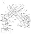
- FIG. 1 is an explanatory diagram for explaining an overview of a robot system 1 according to an embodiment.
- a reference coordinate system ⁇ 0 fixed in real space is introduced as the base coordinate system of the robot 10.
- the reference coordinate system ⁇ 0 is a three-axis Cartesian coordinate system having an origin at the center of the bottom surface BDPbt of the robot 10 (described later) and an X0 axis, a Y0 axis, and a Z0 axis that are mutually orthogonal.
- the robot system 1 includes, for example, a robot 10, an end effector 20 that is detachably attached to the robot 10, and a robot controller 30 that controls the operation of the robot 10 and the end effector 20.
- the robot 10 is an example of a "multi-joint robot," and the robot controller 30 is an example of a "control device.”
- the robot 10 and the robot controller 30 are connected to each other so that they can communicate with each other, for example, via a wired connection.
- the connection between the robot 10 and the robot controller 30 may be a wireless connection, or a connection that uses both wires and wireless connections.
- the robot controller 30 is also capable of communicating with the end effector 20 attached to the robot 10.
- the robot controller 30 may be any information processing device capable of communicating with other devices.
- the robot 10 is an articulated robot used for work in, for example, farms, factories, warehouses, etc.
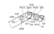
- the robot 10 is an eight-axis articulated robot that is an eight-axis articulated robot that includes six joint mechanisms JEr (JEr1, JEr2, JEr3, JEr4, JEr5, and JEr6) that correspond to rotary joints, and two joint mechanisms JEp (JEp1 and JEp2) that correspond to linear joints.
- the robot 10 includes six joint mechanisms JEr, two joint mechanisms JEp, a body part BDP, two links LK (LK1 and LK2), and a tip part TP1.
- the joint mechanism JEr1 is included in the body part BDP, and the joint mechanisms JEr5 and JEr6 are included in the tip part TP1.
- the joint mechanism JEp1 is provided in the link LK1, and the joint mechanism JEp2 is provided in the link LK2.
- the joint mechanisms JEr and JEp are also referred to as the joint mechanism JE without any particular distinction.
- the robot 10 further has a plurality of motors that drive the plurality of joint mechanisms JE.
- the motors that drive the plurality of joint mechanisms JE, the reducers and encoders provided in each of the plurality of motors, and the like are omitted.
- the plurality of joint mechanisms JE are examples of "multiple joints" and "n joints (n is a natural number equal to or greater than 5).”
- the body part BDP is an example of a "base part.” Additionally, the link LK1 is an example of a "first link,” and the link LK2 is an example of a "second link.” For example, the links LK1 and LK2 connect the body part BDP and the tip part TP1.
- connection of members includes both cases where two members are directly connected and cases where two members are indirectly connected.
- Two members being directly connected includes a state where the two members are in contact with each other, and a state that can be regarded as equivalent to a state where the two members are in contact with each other.
- a state that can be regarded as equivalent to a state where two members are in contact with each other is, for example, a state where one of the two members is fixed to the other with an adhesive or the like.
- two members being indirectly connected means that another member is disposed between the two members.
- Joint mechanism JEr1 is an example of a "first driving mechanism”
- joint mechanism JEr2 is an example of a “second driving mechanism”
- Joint mechanism JEr3 is an example of a “third driving mechanism”
- joint mechanism JEr4 is an example of a "fourth driving mechanism.”
- Joint mechanism JEr5 is an example of a "fifth driving mechanism”
- joint mechanism JEr6 is an example of a “sixth driving mechanism.”
- Joint mechanism JEp1 is an example of a "first moving mechanism”
- joint mechanism JEp2 is an example of a "second moving mechanism.”
- the body part BDP includes a base part BDPba that is fixed to a predetermined location such as a floor, and a joint mechanism JEr1 that is connected to the joint mechanism JEr2.
- the joint mechanism JEr1 rotates a part of the body part BDP around an axis Ax1 that is perpendicular to the bottom surface BDPbt of the body part BDP.
- the joint mechanism JEr1 rotates an outer wall of the joint mechanism JEr1 that includes a part that is connected to the joint mechanism JEr2, relative to the base part BDPba, around the axis Ax1 as the rotation axis.
- the joint mechanism JEr1 rotates the joint mechanism JEr2 relative to the body part BDP, around the axis Ax1 as the rotation axis.
- the axis Ax1 is an example of a "first rotation axis.”
- the rotation direction Dr1 in FIG. 1 indicates the rotation direction of a portion of the body part BDP when that portion rotates around the axis Ax1 as the rotation axis.
- Joint mechanism JEr2 connects body part BDP and link LK1, and rotates link LK1 relative to body part BDP around axis Ax2, which is parallel to the bottom surface BDPbt of body part BDP.
- Rotation direction Dr2 in FIG. 1 indicates the rotation direction of link LK1 when link LK1 rotates around axis Ax2.
- Axis Ax2 is an example of a "second rotation axis.”
- the link LK1 is, for example, hollow and elongated.
- the link LK1 also has an opening Hlk1 that extends in the direction De1 in which the link LK1 extends.
- the direction De1 is the "extension direction of the first link.”
- the opening Hlk1 is formed, for example, on a surface of the link LK1 that includes a portion of the link LK1 that faces the link LK2.
- a portion of the joint mechanism JEr3 and the joint mechanism JEp1 are provided inside the link LK1.
- a portion of the joint mechanism JEr3 is located inside the link LK1, and the other portion of the joint mechanism JEr3 protrudes from the opening Hlk1 to the outside of the link LK1.
- the portion of the joint mechanism JEr3 that protrudes outside the link LK1, or a portion of the portion that protrudes outside the link LK1 passes through an opening Hlk2 in the link LK2 described below and is located inside the link LK2.
- the link LK1 rotates relative to the body part BDP around the axis Ax1 by the joint mechanism JEr1, and rotates relative to the body part BDP around the axis Ax2 by the joint mechanism JEr2.
- Joint mechanism JEr3 connects link LK1 and link LK2, and rotates link LK2 relative to link LK1 around axis Ax3, which is perpendicular to the direction De1 in which link LK1 extends.
- the rotation direction Dr3 in FIG. 1 indicates the rotation direction of link LK2 when link LK2 rotates around axis Ax3.
- axis Ax3 is an example of a "third rotation axis.”
- Joint mechanism JEp1 moves joint mechanism JEr3 relative to link LK1 along direction De1.
- link LK2 moves relative to link LK1 along direction De1.
- the range of movement of joint mechanism JEr3 by joint mechanism JEp1 is preferably a range in which the actual length (controlled length) of link LK1 can be set to less than half the length of link LK1 to more than half the length of link LK1.
- the link LK2 is, for example, hollow and elongated.
- the link LK2 also has an opening Hlk2 that extends in the direction De2 in which the link LK2 extends.
- the direction De2 is the "extension direction of the second link.”
- the opening Hlk2 is formed, for example, in a surface of the link LK2 that includes a portion facing the link LK1.
- a portion of the joint mechanism JEr3 and the joint mechanism JEp2 are provided inside the link LK2.
- a portion of the joint mechanism JEr3 is located inside the link LK2, and the other portion of the joint mechanism JEr3 protrudes from the opening Hlk2 to the outside of the link LK2.
- Joint mechanism JEp2 moves link LK2 relative to joint mechanism JEr3 along direction De2 in which link LK2 extends. As a result, link LK2 moves relative to joint mechanism JEr3 along direction De2. In other words, link LK2 moves relative to link LK1 along direction De2.
- the range of movement of joint mechanism JEr3 by joint mechanism JEp2 is preferably a range in which the effective length (controlled length) of link LK2 can be set to less than half the length of link LK2 to more than half the length of link LK2.
- link LK2 moves relative to link LK1 along direction De1 by joint mechanism JEp1, and moves relative to link LK1 along direction De2 by joint mechanism JEp2.
- Joint mechanism JEr4 connects link LK2 and tip TP1, and rotates tip TP1 relative to link LK2 around axis Ax4 perpendicular to direction De2.
- Rotation direction Dr4 in FIG. 1 indicates the rotation direction of tip TP1 when tip TP1 rotates around axis Ax4.
- Axis Ax4 is an example of a "fourth rotation axis.”
- an end effector 20 that grips an object is attached to the tip part TP1.
- the end effector 20 is attached to the end face TP1sf of the tip part TP1.
- the tip part TP1 includes a first part TP11 connected to the link LK2, a second part TP12 connected to the first part TP11, a joint mechanism JEr5, and a joint mechanism JEr6.
- the first part TP11 is connected to the link LK2 via, for example, the joint mechanism JEr4. Therefore, the first part TP11 rotates relative to the link LK2 around the axis Ax4 as the rotation axis.
- Joint mechanism JEr5 connects the first part TP11 and the second part TP12, and rotates the second part TP12 relative to the first part TP11 around axis Ax5 perpendicular to axis Ax4.
- the rotation direction Dr5 in FIG. 1 indicates the rotation direction of the second part TP12 when the second part TP12 rotates around axis Ax5.
- axis Ax5 is an example of a "fifth rotation axis.”
- the joint mechanism JEr6 rotates at least a part of the tip part TP1 around an axis Ax6 perpendicular to the axis Ax5.
- the joint mechanism JEr6 rotates the end face TP1sf of the tip part TP1 around the axis Ax6. That is, the joint mechanism JEr6 rotates the part of the tip part TP1 to which the end effector 20 is attached (end face TP1sf) around the axis Ax6.
- the rotation direction Dr6 in FIG. 1 indicates the rotation direction of the end face TP1sf when the end face TP1sf rotates around the axis Ax6.
- the axis Ax6 is an example of a "sixth rotation axis.”
- the surface of the joint mechanism JEr6 corresponds to the end surface TP1sf. Note that in a configuration in which the joint mechanism JEr6 is included in the second part TP12, the end surface of the second part TP12 may be the end surface TP1sf.
- the work performed by the end effector 20 is not limited to gripping an object.
- Appropriate parts e.g., robot hands and robot fingers, etc.
- an end effector 20 suitable for various tasks is attached to the tip TP1.
- rotation about an axis whose angle with a specific direction is greater than a predetermined angle may be referred to as "turning" to distinguish it from rotation about an axis whose angle with a specific direction is equal to or less than the predetermined angle.
- the predetermined angle may be, for example, 45°. Note that the predetermined angle is not limited to 45°.
- the direction Dv1 perpendicular to the bottom surface BDPbt of the body part BDP corresponds to the specific direction.
- axis Ax1 corresponds to an axis whose angle with direction Dv1 perpendicular to the bottom surface BDPbt of the body part BDP is equal to or smaller than a predetermined angle
- axis Ax2 corresponds to an axis whose angle with direction Dv1 is greater than a predetermined angle. Therefore, rotation of link LK1 about axis Ax2 as the rotation axis corresponds to a turn.
- the direction Deb in which the body part BDP extends may be the specific direction.
- the direction De1 in which link LK1 extends corresponds to a specific direction
- the direction De2 in which link LK2 extends corresponds to a specific direction
- axis Ax3 corresponds to an axis that forms an angle with direction De1 in which link LK1 extends that is greater than a predetermined angle
- axis Ax4 corresponds to an axis that forms an angle with direction De2 in which link LK2 extends that is greater than a predetermined angle. Therefore, rotation of link LK2 about axis Ax3 and rotation of first part TP11 about axis Ax4 correspond to turning.
- the direction De11 corresponds to a specific direction
- the direction De12 corresponds to a specific direction.
- the direction De11 is a direction from the end of the first part TP11 opposite to a specific end to which the joint mechanism JEr5 is connected toward the specific end.
- the direction De11 may be considered as the direction in which the first part TP11 extends.
- the direction De12 is a direction from the end of the second part TP12 opposite to a specific end (the end including the end face TP1sf) to which the joint mechanism JEr6 is connected toward the specific end.
- the direction De12 may be considered as the direction in which the second part TP12 extends.
- the axis Ax5 corresponds to an axis whose angle with the direction De11 is equal to or smaller than a predetermined angle.
- the axis Ax6 corresponds to an axis whose angle with the direction De12 is equal to or smaller than a predetermined angle.
- the direction De11 is perpendicular to the axis Ax4
- the direction De12 is perpendicular to the axis Ax5.
- the axis Ax5 whose angle with the direction De11 is equal to or smaller than a predetermined angle corresponds to an axis whose angle with the axis Ax4 is larger than a predetermined angle
- the axis Ax6 whose angle with the direction De12 is equal to or smaller than a predetermined angle corresponds to an axis whose angle with the axis Ax5 is larger than a predetermined angle.
- each of the multiple parts of the robot 10 (body part BDP, link LK1, link LK2, tip part TP1, etc.) can rotate around each of the axes Ax1, Ax2, Ax3, Ax4, Ax5, and Ax6. This allows the robot 10 to perform the same movements as a human being.
- the link LK1 between joint mechanism JEr2 and joint mechanism JEr3 corresponds to the upper arm
- the link LK2 between joint mechanism JEr3 and joint mechanism JEr4 corresponds to the forearm.
- the robot 10 can perform a motion that imitates the twisting of a human waist using joint mechanism JEr1, and can perform a motion that imitates the rotation of a shoulder using joint mechanism JEr2.
- the robot 10 can also perform a motion that imitates the rotation of an elbow using joint mechanism JEr3, and can also perform a motion that imitates the rotation of a wrist using joint mechanism JEr4.
- the robot 10 can also perform a motion that imitates the twisting of a wrist using joint mechanism JEr5, and can also perform a motion that imitates the twisting of a fingertip using joint mechanism JEr6.
- the joint mechanism JEp1 provided in the link LK1 allows the link LK2 to move relative to the link LK1 along the direction De1 in which the link LK1 extends.
- the joint mechanism JEp2 provided in the link LK2 allows the link LK2 to move relative to the link LK1 along the direction De2 in which the link LK2 extends. Therefore, in this embodiment, the joint mechanisms JEp1 and JEp2 allow the tip part TP1 of the robot 10 to be easily moved to the periphery of the body part BDP.
- the joint mechanisms JEp1 and JEp2 allow the area reachable by the tip part TP1 (more specifically, the end surface TP1sf) to be widened, thereby widening the area reachable by the end effector 20 attached to the robot 10.
- the configuration of the robot system 1 is not limited to the example shown in FIG. 1.
- the robot controller 30 may be built into the robot 10.
- FIG. 1 illustrates a case in which the robot 10 is fixed to a predetermined location such as a floor
- the robot 10 itself may be movable without being fixed to a predetermined location.
- the base part BDPba of the body part BDP may be fixed to a predetermined location such as a floor via a joint mechanism JEr1.
- the body part BDP may be defined without including the joint mechanism JEr1.
- the joint mechanism JEr1 may rotate the base part BDPba around the axis Ax1 as the rotation axis.
- the base part BDPba may be connected to the joint mechanism JEr2.
- one of the two joint mechanisms JEp may be omitted.
- the joint mechanism JEr3 may be fixed to the end of the two ends of the link LK1 that is farther from the body part BDP.
- the joint mechanism JEr3 may be fixed to the end of the two ends of the link LK2 that is farther from the tip part TP1.
- both of the two joint mechanisms JEp may be omitted.
- the robot controller 30 calculates joint values representing the state (state of the joint) of each joint mechanism JE, for example, to set the position and posture of the robot 10 to a target position and posture.
- the state of the joint mechanism JE may be the state of the movement of the joint.
- the state of the joint mechanism JE may be, for example, the position of the joint mechanism JE (position of the joint) and the rotation angle (direction of the joint) of the rotation by the joint mechanism JEr.
- the joint value indicates, for example, the position of the joint mechanism JE (position of the joint) and the rotation angle (direction of the joint) of the rotation by the joint mechanism JEr.
- the joint value representing the state (state of the joint) of the joint mechanism JE is also simply referred to as the joint value of the joint mechanism JE (joint).
- the operation of the robot 10 is controlled using, for example, forward kinematics, which determines the position and orientation of the robot 10 from the displacement of the joints (e.g., rotation and linear motion, etc.), and inverse kinematics, which determines the displacement of the joints from the position and orientation of the robot 10.
- forward kinematics which determines the position and orientation of the robot 10 from the displacement of the joints
- inverse kinematics which determines the displacement of the joints from the position and orientation of the robot 10.
- the relationship between the speed of the hand (e.g., the tip of the end effector 20) of the robot 10 (hereinafter also referred to as the hand speed) and the joint speed is expressed by equation (1).
- equation (1) is used in the calculation of forward kinematics.
- the hand velocity r( ⁇ ) is expressed by equation (2).
- the joint velocity ⁇ ( ⁇ ) is expressed by equation (3), and the Jacobian matrix J is expressed by equation (4).
- the Jacobian matrix J is expressed, for example, as a matrix with 6 rows and m columns, and the element in the i-th column corresponds to the element J i relating to the i-th joint.
- the element J i relating to the i-th joint is expressed by equation (5) when the i-th joint is a rotational joint, and is expressed by equation (6) when the i-th joint is a prismatic joint. Note that 0 in equation (6) indicates, for example, that the vector value is 0.
- a three-axis Cartesian coordinate system with the origin at a specific position of each joint is associated with each joint (each joint mechanism JE) and is used to express the state of the joint.
- the rotation axis of the joint mechanism JEr corresponds to the Z axis
- the axis along the movement direction of the joint mechanism JEp or the axis along the movement direction of the link LK corresponds to the Z axis.
- the i-th joint mechanism JE counting from the body part BDP in the order of the rotary joint and the linear joint, corresponds to the i-th joint.
- joint mechanism JEr1 corresponds to the first joint
- joint mechanism JEr2 corresponds to the second joint
- Joint mechanism JEr3 corresponds to the third joint
- joint mechanism JEr4 corresponds to the fourth joint
- Joint mechanism JEr5 corresponds to the fifth joint
- joint mechanism JEr6 corresponds to the sixth joint.
- Joint mechanism JEp1 corresponds to the seventh joint
- joint mechanism JEp2 corresponds to the eighth joint.
- the numbering method is not limited to the above example.
- equation (7) The relationship between the hand velocity and the joint velocity of the robot 10 is expressed by the following equation (7) using the pseudo-inverse matrix J + of the Jacobian matrix J.
- equation (7) is used in the calculation of inverse kinematics.
- the robot controller 30 calculates the joint velocity ⁇ i (.) of each joint mechanism JE relative to the target hand velocity r (.) using equation (7), and operates each joint mechanism JE based on the calculation result. Specifically, for example, the robot controller 30 calculates the joint value of each joint mechanism JE based on the joint velocity ⁇ i (.) of each joint mechanism JE calculated using equation (7). Then, the robot controller 30 operates each joint mechanism JE based on the joint value of each joint mechanism JE. For example, the robot controller 30 operates each joint mechanism JE so that the state of each joint mechanism JE becomes a state based on the joint value of each joint mechanism JE.
- the robot 10 can be made to perform a jog operation.
- the jog operation is, for example, an operation in which the joints and hands of the robot 10 are moved little by little to make the posture of the robot 10 reach a target posture.
- the joint velocity ⁇ i (.) and information indicating the state of the joint mechanism JE calculated based on the joint velocity ⁇ i (.) correspond to the joint value.
- the calculation of the joint velocity ⁇ (.) of the joint mechanism JE is an example of an inverse kinematics calculation.
- the pseudo-inverse matrix J + is calculated from the Jacobian matrix J
- calculating the joint velocity ⁇ (.) of the joint mechanism JE using the formula (7) corresponds to performing an inverse kinematics calculation using the Jacobian matrix.
- the joint velocities ⁇ i (.) are calculated for all of the multiple joint mechanisms JE. For this reason, in a control method in which the Jacobian matrix J is used without any modification (hereinafter referred to as a comparative control method), when there are a large number of joint mechanisms JE, the calculation time required to calculate the joint velocities ⁇ i (.) of each joint that change the position and posture of the robot 10 to the target position and posture increases.
- the multiple joint mechanisms JE are divided into two groups, a first group and a second group.
- the robot controller 30 may identify whether each of the multiple joint mechanisms JE belongs to the first group or the second group.
- the joint mechanisms JEr (JEr1, JEr2, JEr3, JEr4, JEr5, and JEr6) belong to the first group
- the joint mechanisms JEp (JEp1 and JEp2) belong to the second group.
- the robot controller 30 then repeatedly executes a unit process that includes a process of sequentially executing a first group process that calculates the joint values of each joint mechanism JE belonging to the first group, and a second group process that calculates the joint values of each joint mechanism JE belonging to the second group.
- a matrix (e.g., a 6-row, 6-column matrix) is used that includes only the elements J1 , J2 , J3 , J4 , J5 , and J6 related to the joint mechanism JEr belonging to the first group among the multiple elements of the Jacobian matrix J.
- a matrix (e.g., a 6-row, 2-column matrix) is used that includes only the elements J7 and J8 related to the joint mechanism JEp belonging to the second group among the multiple elements of the Jacobian matrix J.
- the multiple elements of the Jacobian matrix J are divided into two groups and the inverse kinematics calculation is performed, so that the number of joint mechanisms JE (the number of matrix elements) used in one inverse kinematics calculation can be reduced compared to the control method of the comparative example.
- the solution of the inverse kinematics calculation can be calculated within a desired time.
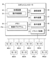
- FIG. 2 is a diagram showing an example of the hardware configuration of the robot controller 30 shown in FIG. 1.
- the robot controller 30 has a processing device 32 that controls each part of the robot controller 30, a memory 35 that stores various information, a communication device 36, an operation device 37 that accepts operations by an operator, etc., a display device 38, and a driver circuit 39.
- the memory 35 includes, for example, one or both of a volatile memory such as a RAM (Random Access Memory) that functions as a working area for the processing device 32, and a non-volatile memory such as an EEPROM (Electrically Erasable Programmable Read-Only Memory) that stores various information such as the control program PGr.
- the memory 35 may be detachable from the robot controller 30.
- the memory 35 may be a storage medium such as a memory card that is detachable from the robot controller 30.
- the memory 35 may also be, for example, a storage device (e.g., online storage) that is communicatively connected to the robot controller 30 via a network or the like.
- the memory 35 shown in FIG. 2 stores the control program PGr.
- the control program PGr is an example of a "program.”
- the control program PGr includes, for example, an application program that causes the robot controller 30 to control the operation of the robot 10.
- the control program PGr may also include, for example, an operating robot system program that causes the processing device 32 to control each part of the robot controller 30.
- the memory 35 includes a computer-readable, non-transient recording medium on which the control program PGr is recorded.
- the processing device 32 is a processor that controls the entire robot controller 30, and is configured to include, for example, one or more CPUs (Central Processing Units).
- the processing device 32 functions as the operation control unit 33 by, for example, executing the control program PGr stored in the memory 35 and operating according to the control program PGr.
- the operation control unit 33 repeats the unit processing described in FIG. 1 until the position and posture of the robot 10 become the target position and posture. Then, the operation control unit 33 drives the robot 10 via a driver circuit 39 described later based on the joint values of each joint mechanism JE, etc.
- the control program PGr may be transmitted from another device via a network, etc.
- the processing device 32 may be configured to include multiple CPUs, some or all of the functions of the processing device 32 may be realized by these multiple CPUs operating in cooperation with each other according to a program such as the control program PGr.
- the processing device 32 may be configured to include hardware such as a GPU (Graphics Processing Unit), a DSP (Digital Signal Processor), or an FPGA (Field Programmable Gate Array) in addition to one or more CPUs, or in place of some or all of the one or more CPUs.
- some or all of the functions of the processing device 32 may be realized by hardware such as a DSP.
- the communication device 36 is hardware for communicating with an external device that exists outside the robot controller 30.
- the communication device 36 has a function of communicating with an external device by short-range wireless communication.
- the communication device 36 may further have a function of communicating with an external device via a mobile communication network or a network.
- the operation device 37 is an input device (e.g., a keyboard, a mouse, a switch, a button, a sensor, etc.) that accepts input from the outside.
- the operation device 37 accepts an operation by an operator and outputs operation information corresponding to the operation to the processing device 32.
- a touch panel that detects contact with the display surface of the display device 38 may be used as the operation device 37.
- the display device 38 is an output device such as a display that outputs to the outside.
- the display device 38 displays images under the control of the processing device 32.
- the operation device 37 and the display device 38 may be integrated into one structure (for example, a touch panel).
- the driver circuit 39 is hardware that outputs signals to the robot 10 to drive the robot 10 under the control of the processing device 32 (more specifically, the operation control unit 33). For example, the driver circuit 39 outputs signals based on the joint values of each joint mechanism JE to the robot 10 as signals to drive motors MOr1, MOr2, MOr3, MOr4, MOr5, MOr6, MOp1, MOp2, etc.
- motors MOr1, MOr2, MOr3, MOr4, MOr5, and MOr6 are motors that drive joint mechanisms JEr1, JEr2, JEr3, JEr4, JEr5, and JEr6, respectively.
- motors MOp1 and MOp2 are motors that drive joint mechanisms JEp1 and JEp2, respectively.
- motors MOr1, MOr2, MOr3, MOr4, MOr5, MOr6, MOp1, and MOp2 may be collectively referred to as motor MO.
- the robot controller 30 controls the operation of the robot 10 by controlling multiple motors MO.
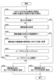
- FIG. 3 is a flow chart showing an example of the operation of the robot controller 30 shown in FIG. 1.
- a process is performed to calculate the joint values of each joint mechanism JE (e.g., information indicating the position of the joint mechanism JE and the rotation angle of the joint mechanism JEr) for changing the position and posture of the hand of the robot 10 to the target position and posture.
- the operation shown in FIG. 3 is executed by the processing device 32 functioning as the operation control unit 33. That is, in each step from step S100 to step S520 shown in FIG. 3, the processing device 32 functions as the operation control unit 33.
- step S100 the operation control unit 33 calculates the difference between the position and posture of the hand of the robot 10 and the target position and posture. For example, the operation control unit 33 calculates the position and posture of the hand of the robot 10 based on the current joint values of each joint mechanism JE. Then, the operation control unit 33 calculates the difference between the position and posture of the hand of the robot 10 calculated based on the current joint values of each joint mechanism JE and the target position and posture of the hand of the robot 10.
- step S120 the operation control unit 33 determines whether the difference between the position and posture of the robot 10's hand and the target position and posture is equal to or less than a tolerance.
- the tolerance is set to a value that indicates that the position and posture of the robot 10's hand can be regarded as matching the target position and posture if the difference between the position and posture of the robot 10's hand and the target position and posture is equal to or less than the tolerance.
- step S120 If the result of the determination in step S120 is positive, the operation control unit 33 advances the process to step S520. On the other hand, if the result of the determination in step S120 is negative, the operation control unit 33 advances the process to step S200.
- step S200 the operation control unit 33 executes a joint value calculation process.
- the joint value calculation process is a process that sequentially executes the first group process and the second group process briefly described in FIG. 1. For example, the joint value calculation process calculates the joint value of each joint mechanism JE. Details of the joint value calculation process will be described later in FIG. 4. After executing the joint value calculation process, the operation control unit 33 advances the process to step S320.
- step S300 the operation control unit 33 determines whether the state of each joint mechanism JE based on the joint values of each joint mechanism JE calculated by the joint value calculation process is within the movable range.
- the movable range of the joint mechanism JE may include the upper and lower limits of the rotation angle of the rotation by the joint mechanism JEr.
- the movable range of the joint mechanism JE may include the movement range (upper and lower limits) of the joint mechanism JEr3 by the joint mechanism JEp1, and the movement range (upper and lower limits) of the joint mechanism JEr3 by the joint mechanism JEp2.
- step S300 If the result of the determination in step S300 is positive, the operation control unit 33 advances the process to step S400. On the other hand, if the result of the determination in step S300 is negative, the operation control unit 33 advances the process to step S320.
- step S320 the operation control unit 33 changes the joint value of the joint mechanism JE that is outside the movable range to a value corresponding to the limit value (upper or lower limit) of the movable range. For example, the operation control unit 33 changes the joint value of the joint mechanism JE that has exceeded the upper limit of the movable range to a value corresponding to the upper limit of the movable range. Similarly, the operation control unit 33 changes the joint value of the joint mechanism JE that has fallen below the lower limit of the movable range to a value corresponding to the lower limit of the movable range. After executing the processing of step S320, the operation control unit 33 advances the processing to step S400.
- the limit value upper or lower limit
- step S400 the operation control unit 33 increments the loop count. Note that the loop count is initialized to 0 before the operation shown in FIG. 3 is executed.
- step S420 the operation control unit 33 determines whether the loop count is equal to or less than an upper limit.
- the upper limit is the upper limit for the number of times the series of processes from step S100 to step S520 is repeated, and is set in order to terminate the operation shown in FIG. 3 if the operation does not converge.
- step S420 If the result of the determination in step S420 is negative, the operation control unit 33 advances the process to step S500. On the other hand, if the result of the determination in step S420 is positive, the operation control unit 33 returns the process to step S100. In this way, the series of processes from step S100 to step S420 are repeated until the joint values of each joint mechanism JE for bringing the position and posture of the hand of the robot 10 to the target position and posture are calculated, or until the loop count exceeds the upper limit. Note that the series of processes from step S100 to step S420 is an example of a "unit process".
- step S500 the operation control unit 33 determines the joint values of each joint mechanism JE calculated in the joint value calculation process in step S200 (the latest joint values) as the joint values of each joint mechanism JE, and sets the completion flag to invalid.
- the completion flag is a flag indicating whether or not joint values have been calculated that make the difference between the position and posture of the robot 10's hand and the target position and posture less than or equal to the tolerance. For example, an invalid completion flag indicates that joint values have not been calculated that make the difference between the position and posture of the robot 10's hand and the target position and posture less than or equal to the tolerance.
- a valid completion flag indicates that joint values have been calculated that make the difference between the position and posture of the robot 10's hand and the target position and posture less than or equal to the tolerance.
- the completion flag is set to valid in step S520, which is executed when the result of the determination in step S120 is positive.
- step S520 the operation control unit 33 determines the joint values (latest joint values) of each joint mechanism JE used in calculating the position and posture of the hand of the robot 10 in step S100 as the joint values of each joint mechanism JE, and sets the completion flag to active. Note that if the series of processes from step S100 to step S520 has been repeated two or more times, the latest joint values used in the current process of step S100 are the joint values calculated in the previous joint value calculation process of step S200.
- the operation shown in FIG. 3 ends when the processing of step S500 or S520 is executed.
- the operation of the robot controller 30 is not limited to the example shown in FIG. 3.
- the processes of steps S400 and S420 may be omitted.
- the operation control unit 33 returns the process to step S100.
- the operations shown in FIG. 3 may be terminated by interrupt processing, etc.
- FIG. 4 is a flow chart showing an example of the joint value calculation process shown in FIG. 3.
- the processing device 32 functioning as the motion control unit 33 executes a series of processes from step S220 to step S264 shown in FIG. 4 as the process of step S220 shown in FIG. 3. Therefore, the process of step S220 is executed when the result of the determination in step S120 shown in FIG. 3 is negative.
- step S220 the movement control unit 33 calculates the Jacobian matrix J of the first group corresponding to the joint mechanisms JE belonging to the first group based on the current joint values of each joint mechanism JE. Specifically, for example, the movement control unit 33 calculates a 6-row, 6-column Jacobian matrix including only the elements (J 1 -J 6 ) of the columns corresponding to the joint mechanisms JEr (JEr1-JEr6) belonging to the first group as the Jacobian matrix J of the first group.
- step S222 the motion control unit 33 calculates the displacement amount of each joint mechanism JEr belonging to the first group (for example, the joint velocity ⁇ i ( ⁇ ) of each joint mechanism JEr) using the pseudo-inverse matrix J+ of the Jacobian matrix J of the first group.
- step S224 the operation control unit 33 updates the joint values of each joint mechanism JE based on the displacement amount of each joint mechanism JE. For example, the operation control unit 33 adds the displacement amount of each joint mechanism JEr (JEr1-JEr6) belonging to the first group to the joint value of each joint mechanism JEr (JEr1-JEr6) used to calculate the position and posture of the hand of the robot 10 in step S100 shown in FIG. 3. This updates the joint value of each joint mechanism JEr belonging to the first group. Note that the joint values of each joint mechanism JEp (JEp1 and JEp2) belonging to the second group are maintained at the joint value used in step S100 because the displacement amount has not been calculated in the series of processes in steps S220 and S222.
- step S240 the operation control unit 33 calculates the difference between the position and posture of the hand of the robot 10 and the target position and posture. For example, the operation control unit 33 calculates the position and posture of the hand of the robot 10 based on the current joint values of each joint mechanism JE (joint values updated in step S224). Then, the operation control unit 33 calculates the difference between the position and posture of the hand of the robot 10 calculated based on the current joint values of each joint mechanism JE and the target position and posture of the hand of the robot 10.
- step S260 the operation control unit 33 calculates a Jacobian matrix J of the second group corresponding to the joint mechanisms JE belonging to the second group based on the current joint values of each joint mechanism JE. Specifically, for example, the operation control unit 33 calculates a 6-row, 2-column Jacobian matrix including only elements ( J7 and J8 ) in the columns corresponding to the joint mechanisms JEp (JEp1 and JEp2) belonging to the second group as the Jacobian matrix J of the second group. That is, the joint values of the joint mechanisms JE belonging to the first group are fixed to the values calculated by the series of processes from step S220 to S224.
- step S262 the motion control unit 33 calculates the displacement amount of each joint mechanism JEp belonging to the second group (for example, the joint velocity ⁇ i ( ⁇ ) of each joint mechanism JEp) using the pseudo-inverse matrix J+ of the Jacobian matrix J of the second group.
- step S264 the operation control unit 33 updates the joint values of each joint mechanism JE based on the displacement amount of each joint mechanism JE. For example, the operation control unit 33 adds the displacement amount of each joint mechanism JEp (JEp1 and JEp2) belonging to the second group to the joint value of each joint mechanism JEp (JEp1 and JEp2) updated in step S224. That is, the operation control unit 33 adds the displacement amount of each joint mechanism JEp (JEp1 and JEp2) belonging to the second group to the joint value of each joint mechanism JEp (JEp1 and JEp2) used in step S100 shown in FIG. 3. This updates the joint value of each joint mechanism JEp belonging to the second group. In addition, the joint values of each joint mechanism JEr (JEr1-JEr6) belonging to the first group are maintained at the joint values updated in step S224, since the displacement amount has not been calculated in the series of processes in steps S260 and S262.
- step S264 After executing the process of step S264, the operation control unit 33 advances the process to step S300 shown in FIG. 3.
- the joint values of each joint mechanism JEr belonging to the first group are calculated by a series of processes from steps S220 to S224, and the joint values of each joint mechanism JEp belonging to the second group are calculated by a series of processes from steps S240 to S264.
- the joint values of all joint mechanisms JE of the robot 10 are calculated.
- the series of processes from steps S220 to S224 is an example of "first group processing”
- the series of processes from steps S260 to S264 is an example of "second group processing”.
- the process of step S300 may be executed after the "first group process”, and in the unit process next to the one unit process, the "second group process” may be executed if the result of the determination in step S120 is negative.
- the joint values may be determined in step S520 and the calculation may be terminated.
- the joint mechanism JE belonging to the first group in the "first group processing” is a joint mechanism JEr (JEr1-JEr6)
- a Jacobian matrix J with 6 rows and 6 columns is used
- the joint mechanism JE belonging to the second group in the "second group processing” is a joint mechanism JEp (JEp1 and JEp2)
- a Jacobian matrix J with 6 rows and 2 columns is used, but the present invention is not limited to this.
- the present invention can also change the number of columns of the Jacobian matrix J depending on the number of joint mechanisms JE in each group.
- first group processing and “second group processing” may be performed using a 6-row, 8-column Jacobian matrix J based on the joint values of the eight joint mechanisms JE.
- the calculation of the "first group processing” may be performed by setting the matrix related to the calculation of the joint mechanism JEp (JEp1 and JEp2) of the 6-row, 8-column Jacobian matrix J to 0, thereby substantially fixing the joint values of the joint mechanism JEp.
- the calculation of the "second group processing” may be performed by setting the matrix related to the calculation of the joint mechanism JEr (JEr1-JEr6) of the 6-row, 8-column Jacobian matrix J to 0, thereby substantially fixing the joint values of the joint mechanism JEr.
- the first is when the robot 10 is made to perform a jog operation. In the jog operation, a target position is specified for the robot 10, and the angles (movement amounts) of each joint for moving to the specified target position are calculated by inverse kinematics calculation.
- the second is when the trajectory of the robot 10 is generated. When the robot 10 is made to perform repetitive operations, it is necessary to memorize the trajectory in advance. When generating a trajectory in advance, the angles of each joint at multiple points on the trajectory are calculated by inverse kinematics calculation. Note that, if the number of points on the trajectory is small, the trajectory between the points may be calculated and supplemented when the robot 10 is actually operated.
- the third is when the robot 10 is equipped with a vision camera or the like, and the trajectory of the robot 10 is generated (or the trajectory is corrected) based on vision information or the like. In this case, a new target position is specified as in the first jog operation.
- the robot system 1 includes the robot 10, which is a multi-joint robot having four or more joint mechanisms JE, and the robot controller 30 that controls the operation of the robot 10.
- the joint mechanisms JE are divided into two groups, a first group and a second group.
- the control method for the robot 10 is a control method that calculates the joint values of each of the multiple joint mechanisms JE for bringing the robot 10 into a desired state by repeatedly executing unit processes including a first group process that calculates joint values representing the state of the joint mechanisms JE for the joint mechanisms JE belonging to the first group by performing an inverse kinematics calculation that calculates the displacement amount of the joint mechanisms JE when the robot 10 is operated using the joint mechanisms JE belonging to the first group among the multiple joint mechanisms JE, and a second group process that calculates joint values of the joints belonging to the second group by performing an inverse kinematics calculation using the joint mechanisms JE belonging to the second group among the multiple joint mechanisms JE.
- the robot controller 30 has an operation control unit 33 that repeatedly executes the above-mentioned unit processing.
- the control program PGr causes the processing device 32 included in the robot controller 30 to function as the above-mentioned operation control unit 33.
- the inverse kinematics calculation for calculating the joint values of all the joint mechanisms JE of the robot 10 is performed twice. For example, in a unit process, first, an inverse kinematics calculation for calculating the joint values of the joint mechanisms JE belonging to the first group is performed, and then an inverse kinematics calculation for calculating the joint values of the joint mechanisms JE belonging to the second group is performed. For this reason, in this embodiment, the number of joint mechanisms JE used in one inverse kinematics calculation (the number of joint mechanisms JE treated as displacing joint mechanisms JE) can be reduced compared to conventional control methods. As a result, in this embodiment, the calculation time required for one inverse kinematics calculation can be shortened.
- the robot 10 has four or more joint mechanisms JE including one joint mechanism JEp (linear joint).
- the second group includes one joint mechanism JEp. Even in this case, it is possible to suppress an increase in the calculation time until the solution of the inverse kinematics calculation is calculated.
- the four or more joint mechanisms JE including one joint mechanism JEp (linear joint) may include two or more joint mechanisms JEp corresponding to the linear joints.
- the robot 10 has eight or more joint mechanisms JE including two joint mechanisms JEp (linear joints).
- the second group includes two joint mechanisms JEp. Even in this case, it is possible to suppress an increase in the calculation time until the solution of the inverse kinematics calculation is calculated.
- the eight or more joint mechanisms JE including two joint mechanisms JEp (linear joints) may include three or more joint mechanisms JEp corresponding to linear joints.
- the robot 10 includes a body part BDP, a link LK1, a link LK2, a tip part TP1, a joint mechanism JEr1 that rotates at least a part of the body part BDP around an axis Ax1 that forms an angle with a direction Dv1 perpendicular to the bottom surface BDPbt of the body part BDP of less than a predetermined angle as a first rotation axis, which connects the body part BDP and the link LK1, and rotates the link LK1 around an axis Ax2 that forms an angle with the direction Dv1 perpendicular to the bottom surface BDPbt of the body part BDP of more than a predetermined angle as a second rotation axis, which connects the link LK1 and the link LK2, and rotates the link LK1 around an axis Ax2 that forms an angle with the direction De1 in which the link LK1 extends of more than a predetermined angle as a second rotation axis, which connects
- the tip part TP1 includes a first part TP11 connected to the link LK2, a second part TP12 connected to the first part TP11, a joint mechanism JEr5 that connects the first part TP11 and the second part TP12 and rotates the second part TP12 relative to the first part TP11 around an axis Ax5 that forms an angle with the fourth rotation axis greater than a predetermined angle as a fifth rotation axis, and a joint mechanism JEr6 that rotates at least a part of the tip part TP1 around an axis Ax6 that forms an angle with the fifth rotation axis greater than a predetermined angle as a sixth rotation axis.
- the multiple joint mechanisms JE are joint mechanism JEr1, joint mechanism JEr2, joint mechanism JEr3, joint mechanism JEr4, joint mechanism JEr5, joint mechanism JEr6, joint mechanism JEp1, and joint mechanism JEp2.
- the robot 10 which is a multi-joint robot including six rotational joints and two linear joints, can be operated continuously.
- the robot system 1 may be used in a manufacturing method for an article that includes assembling or removing a part.
- the work of assembling or removing a part can be performed efficiently.
- the six joint mechanisms JEr (JEr1-JEr6) corresponding to the rotational joints belong to the same group (first group), but the present invention is not limited to such an embodiment.
- the six joint mechanisms JEr (JEr1-JEr6) may be divided into two groups. Specifically, for example, among the eight joint mechanisms JE, three joint mechanisms JEr4, JEr5, and JEr6 may belong to the first group, and the remaining five joint mechanisms JEr1, JEr2, JEr3, JEp1, and JEp2 may belong to the second group.
- the eight joint mechanisms JE may belong to the first group, and the remaining three joint mechanisms JEr4, JEr5, and JEr6 may belong to the second group. Furthermore, even in a configuration in which one or both of the two joint mechanisms JEp are omitted from the multiple joint mechanisms JE, the multiple joint mechanisms JE may be divided in the same manner as in the above-mentioned example.
- the three joint mechanisms JEr6, JEr5, and JEr4 that are the first, second, and third from the tip of the robot 10 may belong to the first group.
- the remaining joint mechanisms JE (JEr1, JEr2, JEr3, JEp1, and JEp2) may belong to the second group. In this case as well, the same effects as in the above-mentioned embodiment can be obtained.
- the three joint mechanisms JEr6, JEr5, and JEr4 that are the first, second, and third from the tip of the robot 10 may belong to the second group.
- the remaining joint mechanisms JE (JEr1, JEr2, JEr3, JEp1, and JEp2) may belong to the first group. In this case as well, the same effects as in the above-mentioned embodiment can be obtained.
- the multiple joint mechanisms JE may be divided into three or more groups.
- the six joint mechanisms JEr (JEr1-JEr6) corresponding to the rotary joints may be divided into two groups as in the first modified example described above, and the two joint mechanisms JEp corresponding to the linear joints may belong to the third group (third group).
- the grouping when dividing the multiple joint mechanisms JE into three or more groups is not limited to the above-described example.
- FIG. 5 is a flowchart showing an example of a joint value calculation process according to the second modified example. Elements similar to those described in FIGS. 1 to 4 are given the same reference numerals, and detailed description will be omitted.
- the joint value calculation process i.e., the series of processes from step S210 to step S240 shown in FIG. 5 is also executed by the processing device 32 functioning as the operation control unit 33.
- the series of processes from step S210 to step S240 shown in FIG. 5 is executed as the process of step S220 shown in FIG. 3, instead of the series of processes from step S220 to step S264 shown in FIG. 4. Therefore, the process of step S210 is executed when the result of the determination in step S120 shown in FIG. 3 is negative.
- n joint mechanisms JE (n is a natural number equal to or greater than 5) are divided into k groups (k is a natural number equal to or greater than 3 and equal to or less than n/2 rounded up or down).
- step S210 the operation control unit 33 sets the variable h to 1. Then, the operation control unit 33 advances the process to step S220.
- step S220 the operation control unit 33 calculates the Jacobian matrix J (hereinafter also referred to as the Jacobian matrix J of the h-th group) corresponding to the joint mechanism JE belonging to the h-th group (h-th group) based on the current joint values of each joint mechanism JE.
- the calculation process of the Jacobian matrix J of the h-th group is similar to the calculation process of the Jacobian matrix J of the first group (step S220 in FIG. 4) and the calculation process of the Jacobian matrix J of the second group (step S260 in FIG. 4) described in FIG. 4.
- step S222 the motion control unit 33 calculates the displacement amount of each joint mechanism JE belonging to the h-th group (for example, the joint velocity ⁇ i ( ⁇ ) of each joint mechanism JE) using the pseudo-inverse matrix J + of the Jacobian matrix J of the h-th group.
- step S224 the operation control unit 33 updates the joint value of each joint mechanism JE based on the displacement amount of each joint mechanism JE. For example, the operation control unit 33 adds the displacement amount of each joint mechanism JE belonging to the h-th group to the current joint value of each joint mechanism JE. This updates the joint value of each joint mechanism JE belonging to the h-th group.
- the joint values of joint mechanisms JE other than the joint mechanism JE belonging to the h-th group are maintained at the latest joint value before the processing of step S224 is executed, since the displacement amount has not been calculated in the series of processing of steps S220 and S222.
- the joint values of joint mechanisms JE other than the joint mechanism JE belonging to the h-th group are fixed to the latest joint value before the processing of step S224 is executed.
- step S232 the movement control unit 33 determines whether the variable h is less than or equal to k (the number of groups). If the result of the determination in step S232 is negative, the movement control unit 33 ends the joint value calculation process and proceeds to step S300 shown in FIG. 3. On the other hand, if the result of the determination in step S232 is positive, the movement control unit 33 proceeds to step S240.
- step S240 the operation control unit 33 calculates the difference between the position and posture of the hand of the robot 10 and the target position and posture. For example, the operation control unit 33 calculates the position and posture of the hand of the robot 10 based on the current joint values of each joint mechanism JE (joint values updated in step S224). Then, the operation control unit 33 calculates the difference between the position and posture of the hand of the robot 10 calculated based on the current joint values of each joint mechanism JE and the target position and posture of the hand of the robot 10.
- step S240 After executing the process of step S240, the operation control unit 33 returns the process to step S220.
- the joint values of each joint mechanism JE belonging to the h-th group are calculated by a series of processes from steps S220 to S224.
- the series of processes from steps S220 to S224 and the process of step S240 are repeated the number of times (k) for the group, thereby calculating the joint values of all joint mechanisms JE of the robot 10.
- the series of processes from steps S220 to S224 is an example of "group processing”.
- the joint value calculation process shown in FIG. 5 may be executed as the process of step S220 shown in FIG. 3.
- n joint mechanisms JE (n is a natural number of 5 or more) are divided into k groups (k is a natural number of 3 or more and less than or equal to n/2 rounded up).
- the operation control unit 33 calculates joint values representing the states of the n joint mechanisms JE for bringing the robot 10 into a target state by repeatedly executing unit processes including a process of sequentially executing k group processes corresponding to the k groups.
- the operation control unit 33 calculates the joint values of the joint mechanisms JE belonging to one group by performing an inverse kinematic calculation to calculate the displacement amount of the joint mechanism JE when the robot 10 is operated using a joint mechanism JE belonging to one group among the multiple joint mechanisms JE.
- the same effects as those of the above-mentioned embodiment can be obtained.
- the joint mechanism JEr3 moves relative to the link LK1 or LK2, but the present invention is not limited to this.
- the robot 10 may have a joint mechanism JE that expands and contracts the link LK1 and a joint mechanism JE that expands and contracts the link LK2, instead of the joint mechanisms JEp1 and JEp2.
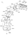
- FIG. 6 is an explanatory diagram for explaining an example of a robot 10 according to a third modified example. Elements similar to those explained in FIGS. 1 to 5 are given the same reference numerals, and detailed explanations are omitted.
- the robot 10 according to this modified example is, for example, an eight-axis articulated robot having a joint mechanism JEe (JEe1 and JEe2) instead of the joint mechanism JEp (JEp1 and JEp2) shown in FIG. 1.
- the joint mechanism JEe1 is a linear joint that causes the link LK1A, which includes the support part LK1a, the movable part LK1b, and the movable part LK1c, to expand and contract along the direction De1.
- the joint mechanism JEe2 is a linear joint that causes the link LK2A, which includes the support part LK2a, the movable part LK2b, and the movable part LK2c, to expand and contract along the direction De2.
- the robot 10 has joint mechanisms JEr1A, JEr2, JEr3A, JEr4A, JEr5A, JEr6, JEe1, and JEe2, a body part BDPa, links LK1A and LK2A, and a tip part TP1A.
- the joint mechanism JEe1 is provided on the link LK1A
- the joint mechanisms JEe2 and JEr4A are provided on the link LK2A.
- Body part BDPa is an example of a "base part.”
- Joint mechanism JEr1A is an example of a "first drive mechanism”
- joint mechanism JEr3A is an example of a “third drive mechanism”
- joint mechanism JEr5A is an example of a "fifth drive mechanism.”
- Joint mechanism JEe1 is an example of a "first telescopic mechanism”
- joint mechanism JEe2 is an example of a “second telescopic mechanism.”
- Link LK1A is an example of a "first link”
- link LK2A is an example of a "second link.”
- the body part BDPa is fixed to a predetermined location, such as the floor, via the joint mechanism JEr1A.
- the joint mechanism JEr1A rotates the body part BDPa around an axis Ax1 that is perpendicular to the bottom surface BDPbt of the body part BDPa.
- the joint mechanism JEr2 connects the body part BDPa and the support part LK1a of the link LK1A, and rotates the link LK1A relative to the body part BDPa around the axis Ax2 that is parallel to the bottom surface BDPbt of the body part BDPa.
- the link LK1A is configured to be expandable and contractible, for example, along the direction De1 in which the link LK1A extends.
- the link LK1A includes a support part LK1a connected to the body part BDPa, movable parts LK1b and LK1c, and a joint mechanism JEe1.
- the support part LK1a is an example of a "first support part”
- the movable part LK1c is an example of a "first movable part.”
- the movable part LK1b is connected to the movable part LK1c so as to move integrally with the movable part LK1c, and is connected to the support part LK1a so as to be movable relative to the support part LK1a.
- the joint mechanism JEe1 moves the movable part LK1b along the direction De1 relative to the support part LK1a, thereby moving the movable part LK1c along the direction De1 relative to the support part LK1a.
- the link LK1A expands and contracts along the direction De1.
- the support part LK1a is hollow. When the link LK1A contracts, at least a part of the movable part LK1b is stored inside the support part LK1a.
- Joint mechanism JEr3A connects movable portion LK1c of link LK1A and support portion LK2a of link LK2A, and rotates link LK2A relative to link LK1A around axis Ax3 perpendicular to the direction De1 in which link LK1A extends.
- Link LK2A is configured to be expandable and contractible, for example, along the direction De2 in which link LK2A extends.
- link LK2A includes a support part LK2a connected to the movable part LK1c of link LK1A, movable parts LK2b and LK2c, a joint mechanism JEe2, and a joint mechanism JEr4A.
- Support part LK2a is an example of a "second support part”
- movable part LK2c is an example of a "second movable part.”
- the movable part LK2b is connected to the movable part LK2c so as to move integrally with the movable part LK2c, and is connected to the support part LK2a so as to be movable relative to the support part LK2a.
- the joint mechanism JEe2 moves the movable part LK2b along the direction De2 relative to the support part LK2a, thereby moving the movable part LK2c along the direction De2 relative to the support part LK2a.
- the support part LK2a is hollow. When the link LK2A contracts, at least a part of the movable part LK2b is stored inside the support part LK2a.
- the joint mechanism JEr4A rotates the movable part LK2c relative to the support part LK2a around an axis Ax4A that is parallel to the direction De2 in which the link LK2A extends.
- the joint mechanism JEr4A is an example of a "fourth drive mechanism," and the axis Ax4A is an example of a "fourth rotation axis.”
- the joint mechanism JEr5A connects the movable part LK2c of the link LK2A to the tip TP1A, and rotates the tip TP1A relative to the link LK2A around an axis Ax5 perpendicular to the direction De2 in which the link LK2A extends.
- the tip part TP1A includes a second part TP12A connected to the movable part LK2c of the link LK2 via a joint mechanism JEr5A, and a joint mechanism JEr6.
- the joint mechanism JEr6 is similar to the joint mechanism JEr6 shown in FIG. 1.
- the end effector 20 is attached to the end surface TP1sf.
- the configuration of the robot 10 according to this modified example is not limited to the example shown in FIG. 6.
- the joint mechanism JEr4A moves along the direction De2 relative to the support part LK2a together with the movable part LK2c of the link LK2A, but may be fixed to the support part LK2a.
- the joint mechanism JEr4A may rotate the movable part LK2b relative to the support part LK2a around the axis Ax4A as the rotation axis, and the joint mechanism JEe2 may move the movable part LK2c relative to the movable part LK2b.
- the movable part LK2b In a configuration in which the movable part LK2c moves relative to the movable part LK2b, for example, the movable part LK2b is hollow. Then, when the link LK2A contracts, at least a part of the movable part LK2c is stored inside the movable part LK2b. Also, one of the joint mechanisms JEe1 and JEe2 may be omitted.
- the robot 10 comprises a body part BDPa, a link LK1A including a support part LK1a and a movable part LK1c, a link LK2A including a support part LK2a and a movable part LK2c, a tip part TP1A, and a joint mechanism JEr1A that rotates at least a part of the body part BDPa around an axis Ax1 that forms an angle with a direction Dv1 perpendicular to the bottom surface BDPbt of the body part BDPa that is equal to or smaller than a predetermined angle as a first rotation axis, and a joint mechanism JEr1A that connects the body part BDPa and the support part LK1a.
- a joint mechanism JEr1A that rotates at least a part of the body part BDPa around an axis Ax1 that forms an angle with a direction Dv1 perpendicular to the bottom surface BDPbt of the body part BDPa that is equal to
- a joint mechanism JEr2 that rotates the link LK1A with respect to the body part BDPa around an axis Ax2 that forms an angle with a direction Dv1 perpendicular to the bottom surface BDPbt of the body part BDPa larger than a predetermined angle as a second rotation axis
- a joint mechanism JEr3A that connects the movable part LK1c and the support part LK2a and rotates the link LK2A with respect to the link LK1A around an axis Ax3 that forms an angle with a direction De1 in which the link LK1A extends larger than a predetermined angle as a third rotation axis
- a joint mechanism JEr4A that rotates the movable part LK2c relative to the support part LK2a around an axis Ax4A that forms an angle with the direction De2 of a predetermined angle or less as a fourth rotation axis
- a joint mechanism JEr5A that connects the movable part LK
- the joint mechanism JE includes a joint mechanism JEr6 that rotates at least a portion of the tip portion TP1A relative to the link LK2A, a joint mechanism JEe1 that moves the movable portion LK1c relative to the support portion LK1a along the extension direction (direction De1) of the link LK1A to expand and contract the link LK1A, and a joint mechanism JEe2 that moves the movable portion LK2c relative to the support portion LK2a along the extension direction (direction De2) of the link LK2A to expand and contract the link LK2A.
- a joint mechanism JEr6 that rotates at least a portion of the tip portion TP1A relative to the link LK2A
- a joint mechanism JEe1 that moves the movable portion LK1c relative to the support portion LK1a along the extension direction (direction De1) of the link LK1A to expand and contract the link LK1A
- a joint mechanism JEe2 that moves the movable
- the multiple joint mechanisms JE are joint mechanism JEr1A, joint mechanism JEr2, joint mechanism JEr3A, joint mechanism JEr4A, joint mechanism JEr5A, joint mechanism JEr6, joint mechanism JEe1, and joint mechanism JEe2.
- joint mechanism JEr1A joint mechanism JEr2
- joint mechanism JEr3A joint mechanism JEr4A
- joint mechanism JEr5A joint mechanism JEr6
- joint mechanism JEe1 joint mechanism JEr2A
- joint mechanism JEr6 joint mechanism JEe1 joint mechanism JEr6 joint mechanism JEe1
- joint mechanism JEe2 joint mechanism JEr1A
- joint mechanism JEr3A joint mechanism JEr4A
- joint mechanism JEr5A joint mechanism JEr6 joint mechanism JEe1
- the joint mechanism JEr4 rotates the tip portion TP1 relative to the link LK2 around the axis Ax4 perpendicular to the direction De2 in which the link LK2 extends, but the present invention is not limited to this.
- the joint mechanism JEr4 may rotate the tip portion TP1 relative to the link LK2 around an axis that forms an angle with the direction De2 in which the link LK2 extends of a predetermined angle or less.
- FIG. 7 is an explanatory diagram for explaining an example of a tip portion TP1B according to the fourth modified example. Elements similar to those explained in FIGS. 1 to 6 are given the same reference numerals and detailed explanations are omitted.
- the robot 10 according to this modified example is similar to the robot 10 shown in FIG. 1, except that it has a link LK2B, a joint mechanism JEr4B, and a tip part TP1B instead of the link LK2, joint mechanism JEr4, and tip part TP1 shown in FIG. 1.
- Link LK2B is similar to link LK2, except that a joint mechanism JEr4B is connected instead of the joint mechanism JEr4.
- link LK2B is an example of a "second link”
- joint mechanism JEr4B is an example of a "fourth drive mechanism.”
- Joint mechanism JEr4B connects link LK2B and tip TP1B, and rotates tip TP1B relative to link LK2B around axis Ax4A, which is parallel to direction De2.
- Rotation direction Dr4 in FIG. 6 shows the rotation direction of tip TP1B when rotating around axis Ax4A.
- axis Ax4A is an example of a "fourth rotation axis,” and corresponds to an axis that forms an angle with direction De2, in which link LK2B extends, that is equal to or smaller than a predetermined angle.
- the tip part TP1B includes a first part TP11A connected to the link LK2B, a second part TP12A connected to the first part TP11A, a joint mechanism JEr5A, and a joint mechanism JEr6.
- the first part TP11A is connected to the link LK2B, for example, via the joint mechanism JEr4B. Therefore, the first part TP11A rotates relative to the link LK2B around the axis Ax4A as the axis of rotation.
- the joint mechanism JEr5A connects the first part TP11A and the second part TP12A, and rotates the second part TP12A relative to the first part TP11A around an axis Ax5 perpendicular to the axis Ax4A.
- the rotation direction Dr5 in FIG. 1 indicates the rotation direction of the second part TP12A when rotating around the axis Ax5.
- the joint mechanism JEr6 is similar to the joint mechanism JEr6 shown in FIG. 1.
- the joint mechanism JEr6 rotates at least a portion of the tip portion TP1B (for example, end surface TP1sf) around an axis Ax6 perpendicular to the axis Ax5.
- the surface of the joint mechanism JEr6 corresponds to the end surface TP1sf, similar to the joint mechanism JEr6 shown in FIG. 1.
- the end surface of the second part TP12A may be the end surface TP1sf.
- the joint mechanism JEr4B rotates the tip part TP1B relative to the link LK2B around the axis Ax4A, which forms an angle with the direction De2 that is equal to or smaller than a predetermined angle, as the fourth rotation axis.
- the tip part TP1B includes a first part TP11A connected to the link LK2B, a second part TP12A connected to the first part TP11A, a joint mechanism JEr5A, and a joint mechanism JEr6.
- the joint mechanism JEr5A connects the first part TP11A and the second part TP12A, and rotates the second part TP12A relative to the first part TP11A around the axis Ax5, which forms an angle with the fourth rotation axis that is greater than a predetermined angle, as the fifth rotation axis.
- the joint mechanism JEr6 rotates at least a portion of the tip part TP1B around the axis Ax6, which forms an angle with the fifth rotation axis that is greater than a predetermined angle, as the sixth rotation axis. This modification can achieve the same effects as the above-described embodiment.
- a multi-joint robot including six rotational joints and two linear joints is exemplified as the robot 10, but the present invention is not limited to such an embodiment.
- the robot 10 may be a multi-joint robot with four to seven axes, or a multi-joint robot with nine or more axes.
- the modified example can also provide the same effects as the above-described embodiment and modified example.
- FIG. 8 is an explanatory diagram for explaining the model used in the simulation.
- the top view of the figure shows the state of the robot 10 as viewed from the +Z0 direction
- the front view of the figure shows the state of the robot 10 as viewed from the +Y0 direction
- the side view of the figure shows the state of the robot 10 as viewed from the +X0 direction.
- the +Z0 direction is the direction indicated by the arrow on the Z0 axis
- the +Y0 direction is the direction indicated by the arrow on the Y0 axis
- the +X0 direction is the direction indicated by the arrow on the X0 axis.
- the origin of the reference coordinate system ⁇ 0 having the Y0 axis and the Z0 axis is the center of the bottom surface BDPbt of the robot 10, as explained in FIG. 1.
- the model used in the simulation will also be referred to as a simulation model.
- the length of link LK1 is, for convenience, the distance between joint mechanisms JEr2 and JEr3, and is set to 425 mm at the shortest and 625 mm at the longest.
- the movable range of joint mechanism JEp1 is in the range of 0 to 200 mm.
- the length of link LK2 is, for convenience, the distance between joint mechanisms JEr3 and JEr4, and is set to 399 mm at the shortest and 599 mm at the longest.
- the movable range of joint mechanism JEp2 is in the range of 0 to 200 mm.
- the distance between joint mechanism JEr2 and the contact surface of robot 10 is set to 78 mm.
- the distance between axis Ax5, which is the rotation axis of joint mechanism JEr5, and end face TP1sf of tip portion TP1 is 50 mm.
- the distance between the central axis of link LK2 and axis Ax6 in the direction along the Z0 axis is 95 mm.
- the distance between axis Ax1, which is the rotation axis of joint mechanism JEr1, and the central axis of link LK1 is 90 mm.
- the distance between the central axis of link LK2 and axis Ax6 in the direction along the Y0 axis is 75.5 mm, and the distance between the central axis of link LK1 and the central axis of link LK2 in the direction along the Y0 axis is 89 mm.
- FIG. 9 is an explanatory diagram for explaining the trajectory of the tip TP1 used in the simulation.
- the position (x, y, z) of the tip TP1 of the robot 10 at the teaching point PT is indicated by the coordinates (x, y, z) of the reference coordinate system ⁇ 0.
- Teaching point PT0 shown in Figure 9 indicates the initial position and posture of the robot 10.
- the position (x, y, z) of the tip part TP1 at teaching point PT0 is (450, -80, 500)
- the posture (Rx, Ry, Rz) of the tip part TP1 at teaching point PT0 is (0, 0, 0).
- the time required to calculate each joint value at each teaching point PT was calculated when the robot 10 is operated from teaching point PT0 (initial position and posture) to teaching points PT1, PT2, PT3, and PT4 in that order.
- FIG. 10 is an explanatory diagram for explaining the teaching points PT for each of multiple trajectory patterns.
- the first pattern is a trajectory that moves in sequence through the four vertices of a cube with sides of 100 mm.
- the position (x, y, z) of tip TP1 is (400, -30, 550) and the orientation (Rx, Ry, Rz) of tip TP1 is (0, 90, 0).
- the position (x, y, z) of tip TP1 is (400, -30, 650) and the orientation (Rx, Ry, Rz) of tip TP1 is (0, 90, 0).
- the position (x, y, z) of tip TP1 is (500, -130, 650) and the orientation (Rx, Ry, Rz) is (0, 90, 0).
- the position (x, y, z) of tip TP1 is (500, -130, 550), and the orientation (Rx, Ry, Rz) of tip TP1 is (0, 90, 0).
- the second pattern is a trajectory that moves in sequence through the four vertices of a cube with sides of 200 mm.
- the position (x, y, z) of tip TP1 is (350, 20, 500), and the orientation (Rx, Ry, Rz) of tip TP1 is (0, 90, 0).
- the position (x, y, z) of tip TP1 is (350, 20, 700), and the orientation (Rx, Ry, Rz) of tip TP1 is (0, 90, 0).
- the position (x, y, z) of tip TP1 is (550, -180, 700), and the orientation (Rx, Ry, Rz) of tip TP1 is (0, 90, 0).
- the position (x, y, z) of tip TP1 is (550, -180, 500), and the orientation (Rx, Ry, Rz) of tip TP1 is (0, 90, 0).
- the position (x, y, z) of tip TP1 is (400, -30, 550), and the orientation (Rx, Ry, Rz) of tip TP1 is (0, 100, 0).
- the position (x, y, z) of tip TP1 is (400, -30, 650), and the orientation (Rx, Ry, Rz) of tip TP1 is (0, 80, 0).
- the position (x, y, z) of tip TP1 is (500, -130, 650), and the orientation (Rx, Ry, Rz) of tip TP1 is (0, 80, 0).
- the position (x, y, z) of tip TP1 is (500, -130, 550), and the orientation (Rx, Ry, Rz) of tip TP1 is (0, 100, 0).
- the position (x, y, z) of tip TP1 is (350, 20, 500), and the orientation (Rx, Ry, Rz) of tip TP1 is (0, 110, 0).
- the position (x, y, z) of tip TP1 is (350, 20, 700), and the orientation (Rx, Ry, Rz) of tip TP1 is (0, 70, 0).
- the position (x, y, z) of tip TP1 is (550, -180, 700), and the orientation (Rx, Ry, Rz) of tip TP1 is (0, 70, 0).
- the position (x, y, z) of tip TP1 is (550, -180, 500), and the orientation (Rx, Ry, Rz) of tip TP1 is (0, 110, 0).
- FIG. 11 is an explanatory diagram for explaining the time required to calculate each trajectory pattern.
- trajectory calculations are performed 100 times for each trajectory pattern, and the average time required for the calculations is shown as the calculation time.
- the first group in step S220 of FIG. 4 is the joint mechanism JEr (JEr1, JEr2, JEr3, JEr4, JEr5, and JEr6)
- the second group in step S260 is the joint mechanism JEp (JEp1 and JEp2).
- FIG. 11 also shows the calculation time when calculations are performed using the conventional calculation method for the model of robot 10 shown in FIG. 8 above.
- FIG. 11 also shows the value of (calculation time required by the conventional calculation method)/(calculation time required by the calculation method of the present invention).
- the conventional calculation method referred to here is a method of calculating one Jacobian matrix for the joint mechanisms JEr (JEr1, JEr2, JEr3, JEr4, JEr5, and JEr6) and the joint mechanisms JEp (JEp1 and JEp2) and performing calculations. In other words, the conventional calculation method does not group the joint mechanisms JE.
- the calculation time of the present invention is shorter than that of the conventional technology for each of the routes from teaching point PT0 (initial position) to teaching point PT1, from teaching point PT1 to teaching point PT2, from teaching point PT2 to teaching point PT3, and from teaching point PT3 to teaching point PT4. It can also be seen that the calculation time of the present invention is 1/45.7 of that of the conventional technology for the route from teaching point PT0 (initial position) to teaching point PT4 via teaching points PT1, PT2, and PT3.
- the calculation time of the present invention is shorter than that of the conventional technology in each of the routes from teaching point PT0 (initial position) to teaching point PT1, from teaching point PT1 to teaching point PT2, from teaching point PT2 to teaching point PT3, and from teaching point PT3 to teaching point PT4.
- the calculation time of the present invention is shorter than that of the conventional technology. For example, it can be seen that the calculation time of the present invention is reduced to 1/63.4 of that of the conventional technology in the second pattern, reduced to 1/39.6 of that of the third pattern, and reduced to 1/26.7 of that of the conventional technology in the fourth pattern.
- the robot system 1 including the robot 10 described in the above embodiment and modified examples may be used in a manufacturing method for an article including assembling or removing a part.
- FIG. 12 is an explanatory diagram for explaining an example of rotation.
- the extension direction Dei in FIG. 12 indicates the direction in which link LKi extends
- the extension direction Dej indicates the direction in which link LKj extends.
- the joint mechanism JEri in FIG. 12 connects link LKi and link LKj, and rotates link LKj relative to link LKi around axis Axi as the rotation axis.
- the rotation about the axis Axi corresponds to a "turn".
- the angle ⁇ between the extension direction Dei of the link LKi and the axis Axi is equal to or less than a predetermined angle
- the rotation about the axis Axi corresponds to a rotation other than a turn (a rotation other than a turn).
- the "rotation" shown in FIG. 12 indicates a rotation other than a turn.
- the predetermined angle is not particularly limited, but in FIG. 12, the predetermined angle is assumed to be 45°.
- the angle ⁇ between the extension direction Dei and the axis Axi is an angle between 0° and 90° among a plurality of angles that are understood as the angle of the axis Axi with respect to the extension direction Dei (for example, four angles for two mutually intersecting straight lines, or 0° and 180° for two parallel straight lines).
- the angle ⁇ between the extension direction Dei of the link LKi and the axis Axi is 90°, which is greater than the specified angle (45°). Therefore, in the first pattern, the rotation of the link LKj around the axis Axi is a rotation. Also, in the first pattern, the extension direction Dej of the link LKj is perpendicular to the axis Axi. Note that in the first pattern, when the link LKj rotates (pivots) around the axis Axi, the angle of the extension direction Dej of the link LKj with respect to the extension direction Dei of the link LKi changes.
- the angle ⁇ between the extension direction Dei of the link LKi and the axis Axi is 0°, which is less than a predetermined angle (45°). Therefore, in the second pattern, the rotation of the link LKj around the axis Axi is a rotation other than a turn. Also, in the second pattern, the extension direction Dej of the link LKj is parallel to the extension direction Dei of the link LKi and the axis Axi. That is, the angle of the extension direction Dej of the link LKj relative to the extension direction Dei of the link LKi is 0°.
- the angle ⁇ between the extension direction Dei of the link LKi and the axis Axi is 0°, which is less than a predetermined angle (45°). Therefore, in the third pattern, the rotation of the link LKj around the axis Axi is a rotation other than a turn. Also, in the third pattern, the extension direction Dej of the link LKj is perpendicular to the extension direction Dei of the link LKi and the axis Axi. That is, the angle of the extension direction Dej of the link LKj with respect to the extension direction Dei of the link LKi is 90°.
- the angle ⁇ between the extension direction Dei of link LKi and the axis Axi is 10°, which is less than the specified angle (45°). Therefore, in the fourth pattern, the rotation of link LKj around the axis Axi is a rotation other than a turn. Also, in the fourth pattern, the extension direction Dej of link LKj is parallel to the axis Axi, and the angle of the extension direction Dej of link LKj relative to the extension direction Dei of link LKi is 10°.
- the angle ⁇ between the extension direction Dei of the link LKi and the axis Axi is 70°, which is greater than the specified angle (45°). Therefore, in the fifth pattern, the rotation of the link LKj around the axis Axi is a rotation. Also, in the fifth pattern, the extension direction Dej of the link LKj is perpendicular to the axis Axi. Note that in the fifth pattern, when the link LKj rotates (pivots) around the axis Axi, the angle of the extension direction Dej of the link LKj with respect to the extension direction Dei of the link LKi changes.
- the angle ⁇ between the extension direction Dei of the link LKi and the axis Axi is 10°, which is less than the specified angle (45°). Therefore, in the sixth pattern, the rotation of the link LKj around the axis Axi is a rotation other than a turn. Also, in the sixth pattern, the extension direction Dej of the link LKj is perpendicular to the axis Axi. Note that in the sixth pattern, when the link LKj rotates around the axis Axi as the rotation axis, the angle of the extension direction Dej of the link LKj with respect to the extension direction Dei of the link LKi changes.
- the angle ⁇ between the extension direction Dei of link LKi and the axis Axi is 70°, which is greater than the specified angle (45°). Therefore, in the seventh pattern, the rotation of link LKj around the axis Axi is a rotation. Also, in the seventh pattern, the extension direction Dej of link LKj is parallel to the axis Axi, and the angle of the extension direction Dej of link LKj relative to the extension direction Dei of link LKi is 70°.
- rotation about axis Axi which forms an angle with extension direction Dei of link LKi greater than a predetermined angle
- turning is also referred to as turning.
- the definition of "turning" is not limited to the above example.
- the following second or third definition may be adopted instead of the first definition.
- the rotation corresponds to a turn. Therefore, in the second definition, when the angle of the extension direction Dej of link LKj relative to the extension direction Dei of link LKi changes due to the rotation of link LKj relative to link LKi, the rotation corresponds to a turn. Therefore, in the second definition, when the angle of the extension direction Dej of link LKj relative to the extension direction Dei of link LKi remains constant even when rotated, the rotation corresponds to a rotation other than a turn.
- the first, fifth, and sixth patterns shown in FIG. 12 correspond to turns, and the second, third, fourth, and seventh patterns correspond to rotation other than a turn.
- the rotation corresponds to a turn. Therefore, in the third definition, if the angle between the extension direction Dej of the link LKj and the rotation axis (axis Axi) of the link LKj is greater than a predetermined angle, the rotation corresponds to a turn. Therefore, in the third definition, if the angle between the extension direction Dej of the link LKj and the rotation axis (axis Axi) of the link LKj is equal to or smaller than a predetermined angle, the rotation corresponds to a rotation other than a turn.
- the first, third, fifth, and sixth patterns shown in FIG. 12 correspond to turns, and the second, fourth, and seventh patterns correspond to rotation other than a turn.
- the relative relationship between two rotations by two joint mechanisms JEr may be defined by focusing on the relationship between the rotation axes of the two adjacent joint mechanisms JEr. Specifically, when the angle between the two rotation axes is equal to or less than a predetermined angle (typically parallel), the two rotations may be considered to be the same type of rotation, and when the angle between the two rotation axes is greater than a predetermined angle (typically perpendicular), the two rotations may be considered to be different types of rotation.
- the same type of rotation means that both rotations are rotations or both rotations are other than rotations, and different types of rotation means that one of the two rotations is a rotation and the other is other than rotation.
- the rotation that is the starting point of the relative relationship may be determined based on, for example, any of the above-mentioned first, second and third definitions.
- the first pattern shown in FIG. 12 corresponds to a rotation in the first, second, and third definitions
- the second pattern corresponds to a rotation other than a rotation in the first, second, and third definitions. Therefore, it is preferable to set the first or second pattern as the rotation that is the starting point of the relative relationship.
- a definition that combines two or more of the above-mentioned first, second, and third definitions may be used.
- rotations that correspond to a turn in all of the two or more definitions being combined may be considered to be a turn, or rotations that correspond to a turn in at least one of the two or more definitions being combined may be considered to be a turn.
- LK1, LK1A, LK2, LK2A, LKi, LKj... links LK1a, LK2a... support parts, LK1b, LK1c, LK2b, LK2c... moving parts, MOr1, MOr2, MOr3, MOr4, MOr5, MOr6, MOp1, MOp2... motors.
Abstract
This method for controlling an articulated robot is a method for controlling an articulated robot having a plurality (at least 4) joints. In this method, a joint value for each joint is calculated in order to set the articulated robot in a target state by repeatedly executing unit processes, the unit processes comprising: a first group process in which a joint value expressing the state of a joint is calculated for a joint(s) belonging to a first group among the plurality of joints which are divided into a first group and a second group by performing an inverse kinematics computation using the joint(s) belonging to the first group; and a second group process in which a joint value of a joint(s) belonging to the second group is calculated by performing an inverse kinematics computation using the joint(s) belonging to the second group among the plurality of joints.
Description
本発明は、多関節ロボットの制御方法、ロボットシステム、プログラム、及び、物品の製造方法に関する。
The present invention relates to a method for controlling an articulated robot, a robot system, a program, and a method for manufacturing an article.
人と同様の動作を行うロボットとして、6自由度の多関節ロボットが知られている。また、近年では、6自由度に冗長自由度を加えた7自由度以上の多関節ロボットの研究が行われている。例えば、特許文献1には、7自由度の多関節ロボットの制御方式が開示されている。
Articulated robots with six degrees of freedom are known as robots that can perform the same movements as humans. In recent years, research has been conducted into articulated robots with seven or more degrees of freedom, which are created by adding redundant degrees of freedom to the six degrees of freedom. For example, Patent Document 1 discloses a control method for an articulated robot with seven degrees of freedom.
ところで、一般的な多関節ロボットでは、ロボットの位置及び姿勢から各関節の変位量を求める逆運動学計算が行われ、逆運動学計算の結果に基づいて各関節の動作が制御される。なお、逆運動学計算では、例えば、関節の数が多い場合、関節の数が少ない場合に比べて、計算の負荷が増加する傾向にある。従って、関節の数が多い場合、関節の数が少ない場合に比べて、逆運動学計算の解(ロボットの位置及び姿勢を目的の位置及び姿勢にする各関節の変位量)が算出されるまでの計算時間が増加する。この場合、ロボットを所望のスピードで動作させるころができなくなる場合がある。このため、逆運動学計算の解が算出されるまでの計算時間が増加することを抑制することが望まれている。
In general, inverse kinematics calculations are performed in order to find the amount of displacement of each joint from the robot's position and posture, and the movement of each joint is controlled based on the results of the inverse kinematics calculations. Note that in inverse kinematics calculations, the calculation load tends to be greater when there are a large number of joints, compared to when there are a small number of joints. Therefore, when there are a large number of joints, the calculation time required to calculate the solution of the inverse kinematics calculation (the amount of displacement of each joint that makes the robot's position and posture the desired position and posture) increases compared to when there are a small number of joints. In this case, it may not be possible to operate the robot at the desired speed. For this reason, it is desirable to suppress the increase in calculation time required to calculate the solution of the inverse kinematics calculation.
本発明の好適な態様に係る多関節ロボットの制御方法は、4個以上の複数の関節を有する多関節ロボットの制御方法であって、前記複数の関節は、第1グループ及び第2グループの2個のグループに分けられ、前記複数の関節のうち、前記第1グループに属する関節を用いて、前記多関節ロボットを動作させる場合の関節の変位量を計算する逆運動学計算を実行することにより、前記第1グループに属する関節について、関節の状態を表す関節値を算出する第1グループ処理と、前記複数の関節のうち、前記第2グループに属する関節を用いて、前記逆運動学計算を実行することにより、前記第2グループに属する関節の前記関節値を算出する第2グループ処理と、を含む単位処理を繰り返し実行することにより、前記多関節ロボットを目的の状態にするための前記複数の関節の各々の前記関節値を算出する。
A method for controlling a multi-joint robot according to a preferred embodiment of the present invention is a method for controlling a multi-joint robot having four or more joints, the joints being divided into two groups, a first group and a second group, and the joint values of each of the joints for bringing the multi-joint robot into a desired state are calculated by repeatedly executing unit processes including: a first group process for calculating joint values representing the state of the joints for the joints belonging to the first group by performing an inverse kinematic calculation to calculate the displacement amount of the joint when the multi-joint robot is operated using the joints belonging to the first group among the joints; and a second group process for calculating the joint values of the joints belonging to the second group by performing the inverse kinematic calculation using the joints belonging to the second group among the joints.
本発明の好適な他の態様に係る多関節ロボットの制御方法は、n個(nは、5以上の自然数)の関節を有する多関節ロボットの制御方法であって、前記n個の関節は、k個(kは、3以上でn/2を四捨五入した値 以下の自然数)のグループに分けられ、前記k個のグループに対応するk個のグループ処理を順に実行する処理を含む単位処理を繰り返し実行することにより、前記多関節ロボットを目的の状態にするための前記n個の関節の各々の状態を表す関節値を算出し、前記単位処理の前記k個のグループ処理の各々において、前記複数の関節のうち、前記一のグループに属する関節を用いて、前記多関節ロボットを動作させる場合の関節の変位量を計算する逆運動学計算を実行することにより、前記一のグループに属する関節の前記関節値を算出する。
A control method for a multi-joint robot according to another preferred aspect of the present invention is a control method for a multi-joint robot having n joints (n is a natural number equal to or greater than 5), in which the n joints are divided into k groups (k is a natural number equal to or greater than 3 and equal to or less than n/2 rounded up or down), and a unit process including a process for sequentially executing k group processes corresponding to the k groups is repeatedly executed to calculate a joint value representing each of the n joints for bringing the multi-joint robot into a target state, and in each of the k group processes of the unit process, an inverse kinematic calculation is executed to calculate the amount of displacement of the joint when the multi-joint robot is operated using a joint belonging to one of the groups among the multiple joints, thereby calculating the joint value of the joint belonging to the one group.
本発明の好適な態様に係るロボットシステムは、4個以上の複数の関節を有する多関節ロボットと、前記多関節ロボットの動作を制御する制御装置と、を備え、前記複数の関節は、第1グループ及び第2グループの2個のグループに分けられ、前記制御装置は、前記複数の関節のうち、前記第1グループに属する関節を用いて、前記多関節ロボットを動作させる場合の関節の変位量を計算する逆運動学計算を実行することにより、前記第1グループに属する関節について、関節の状態を表す関節値を算出する第1グループ処理と、前記複数の関節のうち、前記第2グループに属する関節を用いて、前記逆運動学計算を実行することにより、前記第2グループに属する関節の前記関節値を算出する第2グループ処理と、を含む単位処理を繰り返し実行することにより、前記多関節ロボットを目的の状態にするための前記複数の関節の各々の前記関節値を算出する動作制御部を有する。
A robot system according to a preferred embodiment of the present invention includes a multi-joint robot having four or more joints, and a control device that controls the operation of the multi-joint robot. The joints are divided into two groups, a first group and a second group. The control device has an operation control unit that calculates the joint values of each of the joints to bring the multi-joint robot into a desired state by repeatedly executing unit processes including: a first group process that calculates joint values representing the state of the joints for the joints belonging to the first group by performing an inverse kinematic calculation to calculate the displacement amount of the joint when the multi-joint robot is operated using the joints belonging to the first group among the joints; and a second group process that calculates the joint values of the joints belonging to the second group by performing the inverse kinematic calculation using the joints belonging to the second group among the joints.
本発明の好適な態様に係る物品の製造方法は、上述のロボットシステムにより、部品を組み付ける、又は、部品を取り除く。
In a preferred embodiment of the present invention, a method for manufacturing an article involves assembling or removing parts using the robot system described above.
本発明の好適な態様に係るプログラムは、4個以上の複数の関節を有する多関節ロボットの動作を制御するプログラムであって、前記複数の関節は、第1グループ及び第2グループの2個のグループに分けられ、プロセッサを、前記複数の関節のうち、前記第1グループに属する関節を用いて、前記多関節ロボットを動作させる場合の関節の変位量を計算する逆運動学計算を実行することにより、前記第1グループに属する関節について、関節の状態を表す関節値を算出する第1グループ処理と、前記複数の関節のうち、前記第2グループに属する関節を用いて、前記逆運動学計算を実行することにより、前記第2グループに属する関節の前記関節値を算出する第2グループ処理と、を含む単位処理を繰り返し実行することにより、前記多関節ロボットを目的の状態にするための前記複数の関節の各々の前記関節値を算出する動作制御部として機能させる。
A program according to a preferred embodiment of the present invention is a program for controlling the operation of a multi-joint robot having four or more joints, the joints being divided into two groups, a first group and a second group, and the processor is made to function as an operation control unit that calculates the joint values of each of the joints to bring the multi-joint robot into a desired state by repeatedly executing unit processes including: a first group process that calculates joint values representing the state of the joints for the joints belonging to the first group by performing an inverse kinematic calculation to calculate the displacement amount of the joint when the multi-joint robot is operated using the joints belonging to the first group among the joints; and a second group process that calculates the joint values of the joints belonging to the second group by performing the inverse kinematic calculation using the joints belonging to the second group among the joints.
本発明によれば、逆運動学計算の解が算出されるまでの計算時間が増加することを抑制することができる。
The present invention makes it possible to prevent an increase in the calculation time required to calculate the solution of the inverse kinematics calculation.
以下、本発明を実施するための形態について図面を参照して説明する。なお、各図において、各部の寸法及び縮尺は、実際のものと適宜に異ならせてある。また、以下に述べる実施の形態は、本発明の好適な具体例であるから、技術的に好ましい種々の限定が付されているが、本発明の範囲は、以下の説明において特に本発明を限定する旨の記載がない限り、これらの形態に限られるものではない。
Below, the embodiments for carrying out the present invention will be described with reference to the drawings. Note that in each drawing, the dimensions and scale of each part have been appropriately changed from the actual ones. Furthermore, the embodiments described below are preferred examples of the present invention, and therefore various technically preferable limitations have been added, but the scope of the present invention is not limited to these embodiments unless otherwise specified in the following description to the effect that the present invention is limited in any way.
[1.実施形態]
先ず、図1を参照しながら、実施形態に係るロボットシステム1の概要の一例について説明する。 1. Embodiment
First, an example of an overview of arobot system 1 according to an embodiment will be described with reference to FIG.
先ず、図1を参照しながら、実施形態に係るロボットシステム1の概要の一例について説明する。 1. Embodiment
First, an example of an overview of a
図1は、実施形態に係るロボットシステム1の概要を説明するための説明図である。
FIG. 1 is an explanatory diagram for explaining an overview of a robot system 1 according to an embodiment.
なお、以下では、説明の便宜上、ロボット10のベース座標系として、現実空間に固定された基準座標系Σ0を導入する。例えば、基準座標系Σ0は、後述するロボット10の底面BDPbtの中心に原点を有し、互いに直交するX0軸、Y0軸、及び、Z0軸を有する3軸の直交座標系である。
In the following, for ease of explanation, a reference coordinate system Σ0 fixed in real space is introduced as the base coordinate system of the robot 10. For example, the reference coordinate system Σ0 is a three-axis Cartesian coordinate system having an origin at the center of the bottom surface BDPbt of the robot 10 (described later) and an X0 axis, a Y0 axis, and a Z0 axis that are mutually orthogonal.
ロボットシステム1は、例えば、ロボット10と、ロボット10に着脱可能に取り付けられるエンドエフェクタ20と、ロボット10及びエンドエフェクタ20の動作を制御するロボットコントローラ30とを有する。ロボット10は、「多関節ロボット」の例であり、ロボットコントローラ30は、「制御装置」の例である。
The robot system 1 includes, for example, a robot 10, an end effector 20 that is detachably attached to the robot 10, and a robot controller 30 that controls the operation of the robot 10 and the end effector 20. The robot 10 is an example of a "multi-joint robot," and the robot controller 30 is an example of a "control device."
ロボット10及びロボットコントローラ30は、例えば、有線を用いた接続により、互いに通信可能に接続されている。なお、ロボット10とロボットコントローラ30との接続は、無線を用いた接続であってもよいし、有線及び無線の両方を用いた接続であってもよい。また、ロボットコントローラ30は、ロボット10に取り付けられたエンドエフェクタ20と通信可能である。ロボットコントローラ30としては、他の装置と通信可能な任意の情報処理装置を採用することができる。
The robot 10 and the robot controller 30 are connected to each other so that they can communicate with each other, for example, via a wired connection. The connection between the robot 10 and the robot controller 30 may be a wireless connection, or a connection that uses both wires and wireless connections. The robot controller 30 is also capable of communicating with the end effector 20 attached to the robot 10. The robot controller 30 may be any information processing device capable of communicating with other devices.
ロボット10は、例えば、農場、工場及び倉庫等での作業に用いられる多関節ロボットである。具体的には、ロボット10は、回転関節に対応する6個の関節機構JEr(JEr1、JEr2、JEr3、JEr4、JEr5及びJEr6)を有する6軸多関節ロボットに、直動関節に対応する2個の関節機構JEp(JEp1及びJEp2)を追加した8軸多関節ロボットである。例えば、ロボット10は、6個の関節機構JErと、2個の関節機構JEpと、ボディ部BDPと、2個のリンクLK(LK1及びLK2)と、先端部TP1とを有する。なお、図1に示す例では、関節機構JEr1は、ボディ部BDPに含まれ、関節機構JEr5及びJEr6は、先端部TP1に含まれる。また、関節機構JEp1は、リンクLK1に設けられ、関節機構JEp2は、リンクLK2に設けられる。以下では、関節機構JEr及びJEpは、特に区別せずに、関節機構JEとも称される。例えば、ロボット10は、複数の関節機構JEを駆動する複数のモータをさらに有する。図1では、図を見やすくするために、複数の関節機構JEを駆動する複数のモータ、複数のモータの各々に設けられる減速機及びエンコーダ等の記載を省略している。複数の関節機構JEは、「複数の関節」及び「n個(nは、5以上の自然数)の関節」の例である。
The robot 10 is an articulated robot used for work in, for example, farms, factories, warehouses, etc. Specifically, the robot 10 is an eight-axis articulated robot that is an eight-axis articulated robot that includes six joint mechanisms JEr (JEr1, JEr2, JEr3, JEr4, JEr5, and JEr6) that correspond to rotary joints, and two joint mechanisms JEp (JEp1 and JEp2) that correspond to linear joints. For example, the robot 10 includes six joint mechanisms JEr, two joint mechanisms JEp, a body part BDP, two links LK (LK1 and LK2), and a tip part TP1. In the example shown in FIG. 1, the joint mechanism JEr1 is included in the body part BDP, and the joint mechanisms JEr5 and JEr6 are included in the tip part TP1. The joint mechanism JEp1 is provided in the link LK1, and the joint mechanism JEp2 is provided in the link LK2. Hereinafter, the joint mechanisms JEr and JEp are also referred to as the joint mechanism JE without any particular distinction. For example, the robot 10 further has a plurality of motors that drive the plurality of joint mechanisms JE. In FIG. 1, in order to make the drawing easier to see, the motors that drive the plurality of joint mechanisms JE, the reducers and encoders provided in each of the plurality of motors, and the like are omitted. The plurality of joint mechanisms JE are examples of "multiple joints" and "n joints (n is a natural number equal to or greater than 5)."
ボディ部BDPは、「基部」の例である。また、リンクLK1は、「第1リンク」の例であり、リンクLK2は、「第2リンク」の例である。例えば、リンクLK1及びLK2は、ボディ部BDPと先端部TP1とを接続する。
The body part BDP is an example of a "base part." Additionally, the link LK1 is an example of a "first link," and the link LK2 is an example of a "second link." For example, the links LK1 and LK2 connect the body part BDP and the tip part TP1.
ここで、例えば、部材の接続は、2個の部材が直接的に接続される場合と、2個の部材が間接的に接続される場合との両方を含む。2個の部材が直接的に接続されるとは、2個の部材が互いに接触する状態、及び、2個の部材が互いに接触する状態と同視できる状態を含む。2個の部材が互いに接触する状態と同視できる状態とは、例えば、2個の部材の一方が他方に接着剤等により固定される状態である。また、2個の部材が間接的に接続されるとは、2個の部材の間に他の部材が配置されることを意味する。
Here, for example, the connection of members includes both cases where two members are directly connected and cases where two members are indirectly connected. Two members being directly connected includes a state where the two members are in contact with each other, and a state that can be regarded as equivalent to a state where the two members are in contact with each other. A state that can be regarded as equivalent to a state where two members are in contact with each other is, for example, a state where one of the two members is fixed to the other with an adhesive or the like. Also, two members being indirectly connected means that another member is disposed between the two members.
関節機構JEr1は、「第1駆動機構」の例であり、関節機構JEr2は、「第2駆動機構」の例である。関節機構JEr3は、「第3駆動機構」の例であり、関節機構JEr4は、「第4駆動機構」の例である。また、関節機構JEr5は、「第5駆動機構」の例であり、関節機構JEr6は、「第6駆動機構」の例である。また、関節機構JEp1は、「第1移動機構」の例であり、関節機構JEp2は、「第2移動機構」の例である。
Joint mechanism JEr1 is an example of a "first driving mechanism," and joint mechanism JEr2 is an example of a "second driving mechanism." Joint mechanism JEr3 is an example of a "third driving mechanism," and joint mechanism JEr4 is an example of a "fourth driving mechanism." Joint mechanism JEr5 is an example of a "fifth driving mechanism," and joint mechanism JEr6 is an example of a "sixth driving mechanism." Joint mechanism JEp1 is an example of a "first moving mechanism," and joint mechanism JEp2 is an example of a "second moving mechanism."
ボディ部BDPは、例えば、床等の所定の場所に固定される土台部BDPbaと、関節機構JEr2に接続される関節機構JEr1とを含む。関節機構JEr1は、ボディ部BDPの底面BDPbtに垂直な軸Ax1を回転軸として、ボディ部BDPの一部分を回転させる。例えば、関節機構JEr1は、関節機構JEr1のうち、関節機構JEr2と接続される部分を含む外壁を、軸Ax1を回転軸として土台部BDPbaに対して回転させる。すなわち、関節機構JEr1は、軸Ax1を回転軸として、関節機構JEr2をボディ部BDPに対して回転させる。なお、軸Ax1は、「第1回転軸」の例である。
The body part BDP includes a base part BDPba that is fixed to a predetermined location such as a floor, and a joint mechanism JEr1 that is connected to the joint mechanism JEr2. The joint mechanism JEr1 rotates a part of the body part BDP around an axis Ax1 that is perpendicular to the bottom surface BDPbt of the body part BDP. For example, the joint mechanism JEr1 rotates an outer wall of the joint mechanism JEr1 that includes a part that is connected to the joint mechanism JEr2, relative to the base part BDPba, around the axis Ax1 as the rotation axis. In other words, the joint mechanism JEr1 rotates the joint mechanism JEr2 relative to the body part BDP, around the axis Ax1 as the rotation axis. The axis Ax1 is an example of a "first rotation axis."
ここで、「垂直」は、厳密な垂直だけではなく、実質的な垂直(例えば、誤差範囲内の垂直)も含む。同様に、後述する「平行」は、厳密な平行だけではなく、実質的な平行(例えば、誤差範囲内の平行)も含む。図1の回転方向Dr1は、ボディ部BDPの一部分が軸Ax1を回転軸として回転する場合のボディ部BDPの一部分の回転方向を示す。
Here, "vertical" includes not only strict vertical but also substantial vertical (e.g., vertical within the margin of error). Similarly, "parallel" described below includes not only strict parallel but also substantial parallel (e.g., parallel within the margin of error). The rotation direction Dr1 in FIG. 1 indicates the rotation direction of a portion of the body part BDP when that portion rotates around the axis Ax1 as the rotation axis.
関節機構JEr2は、ボディ部BDPとリンクLK1とを接続し、ボディ部BDPの底面BDPbtに平行な軸Ax2を回転軸としてリンクLK1をボディ部BDPに対して回転させる。図1の回転方向Dr2は、リンクLK1が軸Ax2を回転軸として回転する場合のリンクLK1の回転方向を示す。なお、軸Ax2は、「第2回転軸」の例である。
Joint mechanism JEr2 connects body part BDP and link LK1, and rotates link LK1 relative to body part BDP around axis Ax2, which is parallel to the bottom surface BDPbt of body part BDP. Rotation direction Dr2 in FIG. 1 indicates the rotation direction of link LK1 when link LK1 rotates around axis Ax2. Axis Ax2 is an example of a "second rotation axis."
リンクLK1は、例えば、中空であり、長尺に形成される。また、リンクLK1は、リンクLK1が延在する方向De1に延在する開口Hlk1を有する。方向De1は、「第1リンクの延在方向」である。
The link LK1 is, for example, hollow and elongated. The link LK1 also has an opening Hlk1 that extends in the direction De1 in which the link LK1 extends. The direction De1 is the "extension direction of the first link."
開口Hlk1は、例えば、リンクLK1のうち、リンクLK2に対向する部分を含む面に形成される。リンクLK1の内部には、関節機構JEr3の一部及び関節機構JEp1が設けられる。例えば、関節機構JEr3の一部は、リンクLK1の内部に位置し、関節機構JEr3の他の部分は、開口Hlk1からリンクLK1の外部に出ている。なお、関節機構JEr3のうち、リンクLK1の外部に出ている部分、又は、リンクLK1の外部に出ている部分の一部は、後述するリンクLK2の開口Hlk2を通り、リンクLK2の内部に位置する。
The opening Hlk1 is formed, for example, on a surface of the link LK1 that includes a portion of the link LK1 that faces the link LK2. A portion of the joint mechanism JEr3 and the joint mechanism JEp1 are provided inside the link LK1. For example, a portion of the joint mechanism JEr3 is located inside the link LK1, and the other portion of the joint mechanism JEr3 protrudes from the opening Hlk1 to the outside of the link LK1. Note that the portion of the joint mechanism JEr3 that protrudes outside the link LK1, or a portion of the portion that protrudes outside the link LK1, passes through an opening Hlk2 in the link LK2 described below and is located inside the link LK2.
なお、リンクLK1は、関節機構JEr1により、軸Ax1を回転軸としてボディ部BDPに対して回転し、関節機構JEr2により、軸Ax2を回転軸としてボディ部BDPに対して回転する。
The link LK1 rotates relative to the body part BDP around the axis Ax1 by the joint mechanism JEr1, and rotates relative to the body part BDP around the axis Ax2 by the joint mechanism JEr2.
関節機構JEr3は、リンクLK1とリンクLK2とを接続し、リンクLK1が延在する方向De1に垂直な軸Ax3を回転軸としてリンクLK2をリンクLK1に対して回転させる。図1の回転方向Dr3は、リンクLK2が軸Ax3を回転軸として回転する場合のリンクLK2の回転方向を示す。なお、軸Ax3は、「第3回転軸」の例である。
Joint mechanism JEr3 connects link LK1 and link LK2, and rotates link LK2 relative to link LK1 around axis Ax3, which is perpendicular to the direction De1 in which link LK1 extends. The rotation direction Dr3 in FIG. 1 indicates the rotation direction of link LK2 when link LK2 rotates around axis Ax3. Note that axis Ax3 is an example of a "third rotation axis."
関節機構JEp1は、方向De1に沿って、関節機構JEr3をリンクLK1に対して相対的に移動させる。関節機構JEr3が方向De1に沿って移動することにより、リンクLK2は、方向De1に沿って、リンクLK1に対して相対的に移動する。関節機構JEp1による関節機構JEr3の移動範囲は、リンクLK1の実質的な長さ(制御上の長さ)を、リンクLK1の半分以下の長さから半分以上の長さとすることが可能な範囲が好ましい。
Joint mechanism JEp1 moves joint mechanism JEr3 relative to link LK1 along direction De1. As a result of joint mechanism JEr3 moving along direction De1, link LK2 moves relative to link LK1 along direction De1. The range of movement of joint mechanism JEr3 by joint mechanism JEp1 is preferably a range in which the actual length (controlled length) of link LK1 can be set to less than half the length of link LK1 to more than half the length of link LK1.
リンクLK2は、例えば、中空であり、長尺に形成される。また、リンクLK2は、リンクLK2が延在する方向De2に延在する開口Hlk2を有する。方向De2は、「第2リンクの延在方向」である。
The link LK2 is, for example, hollow and elongated. The link LK2 also has an opening Hlk2 that extends in the direction De2 in which the link LK2 extends. The direction De2 is the "extension direction of the second link."
開口Hlk2は、例えば、リンクLK2のうち、リンクLK1に対向する部分を含む面に形成される。リンクLK2の内部には、関節機構JEr3の一部及び関節機構JEp2が設けられる。例えば、関節機構JEr3の一部は、リンクLK2の内部に位置し、関節機構JEr3の他の部分は、開口Hlk2からリンクLK2の外部に出ている。
The opening Hlk2 is formed, for example, in a surface of the link LK2 that includes a portion facing the link LK1. A portion of the joint mechanism JEr3 and the joint mechanism JEp2 are provided inside the link LK2. For example, a portion of the joint mechanism JEr3 is located inside the link LK2, and the other portion of the joint mechanism JEr3 protrudes from the opening Hlk2 to the outside of the link LK2.
関節機構JEp2は、リンクLK2が延在する方向De2に沿って、リンクLK2を関節機構JEr3に対して相対的に移動させる。これにより、リンクLK2は、方向De2に沿って、関節機構JEr3に対して相対的に移動する。すなわち、リンクLK2は、方向De2に沿って、リンクLK1に対して相対的に移動する。関節機構JEp2による関節機構JEr3の移動範囲は、リンクLK2の実質的な長さ(制御上の長さ)を、リンクLK2の半分以下の長さから半分以上の長さとすることが可能な範囲が好ましい。
Joint mechanism JEp2 moves link LK2 relative to joint mechanism JEr3 along direction De2 in which link LK2 extends. As a result, link LK2 moves relative to joint mechanism JEr3 along direction De2. In other words, link LK2 moves relative to link LK1 along direction De2. The range of movement of joint mechanism JEr3 by joint mechanism JEp2 is preferably a range in which the effective length (controlled length) of link LK2 can be set to less than half the length of link LK2 to more than half the length of link LK2.
このように、リンクLK2は、関節機構JEp1により、方向De1に沿って、リンクLK1に対して相対的に移動し、関節機構JEp2により、方向De2に沿って、リンクLK1に対して相対的に移動する。
In this way, link LK2 moves relative to link LK1 along direction De1 by joint mechanism JEp1, and moves relative to link LK1 along direction De2 by joint mechanism JEp2.
関節機構JEr4は、リンクLK2と先端部TP1とを接続し、方向De2に垂直な軸Ax4を回転軸として、先端部TP1をリンクLK2に対して回転させる。図1の回転方向Dr4は、先端部TP1が軸Ax4を回転軸として回転する場合の先端部TP1の回転方向を示す。なお、軸Ax4は、「第4回転軸」の例である。
Joint mechanism JEr4 connects link LK2 and tip TP1, and rotates tip TP1 relative to link LK2 around axis Ax4 perpendicular to direction De2. Rotation direction Dr4 in FIG. 1 indicates the rotation direction of tip TP1 when tip TP1 rotates around axis Ax4. Axis Ax4 is an example of a "fourth rotation axis."
先端部TP1には、例えば、物品を把持するエンドエフェクタ20が取り付けられる。例えば、先端部TP1の端面TP1sfにエンドエフェクタ20が取り付けられる。先端部TP1は、リンクLK2に接続される第1部分TP11と、第1部分TP11に接続される第2部分TP12と、関節機構JEr5と、関節機構JEr6とを含む。第1部分TP11は、例えば、関節機構JEr4を介してリンクLK2に接続される。従って、第1部分TP11は、軸Ax4を回転軸としてリンクLK2に対して回転する。
For example, an end effector 20 that grips an object is attached to the tip part TP1. For example, the end effector 20 is attached to the end face TP1sf of the tip part TP1. The tip part TP1 includes a first part TP11 connected to the link LK2, a second part TP12 connected to the first part TP11, a joint mechanism JEr5, and a joint mechanism JEr6. The first part TP11 is connected to the link LK2 via, for example, the joint mechanism JEr4. Therefore, the first part TP11 rotates relative to the link LK2 around the axis Ax4 as the rotation axis.
関節機構JEr5は、第1部分TP11と第2部分TP12とを接続し、軸Ax4に垂直な軸Ax5を回転軸として、第2部分TP12を第1部分TP11に対して回転させる。図1の回転方向Dr5は、第2部分TP12が軸Ax5を回転軸として回転する場合の第2部分TP12の回転方向を示す。なお、軸Ax5は、「第5回転軸」の例である。
Joint mechanism JEr5 connects the first part TP11 and the second part TP12, and rotates the second part TP12 relative to the first part TP11 around axis Ax5 perpendicular to axis Ax4. The rotation direction Dr5 in FIG. 1 indicates the rotation direction of the second part TP12 when the second part TP12 rotates around axis Ax5. Note that axis Ax5 is an example of a "fifth rotation axis."
関節機構JEr6は、軸Ax5に垂直な軸Ax6を回転軸として、先端部TP1の少なくとも一部分を回転させる。図1に示す例では、関節機構JEr6は、軸Ax6を回転軸として、先端部TP1の端面TP1sfを回転させる。すなわち、関節機構JEr6は、軸Ax6を回転軸として、先端部TP1のうち、エンドエフェクタ20が取り付けられる部分(端面TP1sf)を回転させる。図1の回転方向Dr6は、端面TP1sfが軸Ax6を回転軸として回転する場合の端面TP1sfの回転方向を示す。なお、軸Ax6は、「第6回転軸」の例である。
The joint mechanism JEr6 rotates at least a part of the tip part TP1 around an axis Ax6 perpendicular to the axis Ax5. In the example shown in FIG. 1, the joint mechanism JEr6 rotates the end face TP1sf of the tip part TP1 around the axis Ax6. That is, the joint mechanism JEr6 rotates the part of the tip part TP1 to which the end effector 20 is attached (end face TP1sf) around the axis Ax6. The rotation direction Dr6 in FIG. 1 indicates the rotation direction of the end face TP1sf when the end face TP1sf rotates around the axis Ax6. The axis Ax6 is an example of a "sixth rotation axis."
図1に示す例では、関節機構JEr6の表面が端面TP1sfに該当する。なお、関節機構JEr6が第2部分TP12に含まれる構成等では、第2部分TP12の端面が端面TP1sfであってもよい。
In the example shown in FIG. 1, the surface of the joint mechanism JEr6 corresponds to the end surface TP1sf. Note that in a configuration in which the joint mechanism JEr6 is included in the second part TP12, the end surface of the second part TP12 may be the end surface TP1sf.
また、エンドエフェクタ20により行われる作業は、物品の把持に限定されない。エンドエフェクタ20としては、ロボット10の作業目的に応じて適切な部品(例えば、ロボットハンド及びロボットフィンガー等)を適用することができる。すなわち、各種作業に適したエンドエフェクタ20が先端部TP1に取り付けられる。
Furthermore, the work performed by the end effector 20 is not limited to gripping an object. Appropriate parts (e.g., robot hands and robot fingers, etc.) can be applied as the end effector 20 depending on the work purpose of the robot 10. In other words, an end effector 20 suitable for various tasks is attached to the tip TP1.
ここで、本実施形態では、特定の方向とのなす角度が所定角度より大きい軸を回転軸とした回転を、特定の方向とのなす角度が所定角度以下の軸を回転軸とした回転と区別して、「旋回」と称する場合がある。所定角度は、例えば、45°であってもよい。なお、所定角度は、45°に限定されない。
In this embodiment, rotation about an axis whose angle with a specific direction is greater than a predetermined angle may be referred to as "turning" to distinguish it from rotation about an axis whose angle with a specific direction is equal to or less than the predetermined angle. The predetermined angle may be, for example, 45°. Note that the predetermined angle is not limited to 45°.
例えば、軸Ax1及びAx2の各々を回転軸とする回転では、ボディ部BDPの底面BDPbtに垂直な方向Dv1が特定の方向に該当する。この場合、軸Ax1は、ボディ部BDPの底面BDPbtに垂直な方向Dv1とのなす角度が所定角度以下の軸に該当し、軸Ax2は、方向Dv1とのなす角度が所定角度より大きい軸に該当する。従って、軸Ax2を回転軸とするリンクLK1の回転は、旋回に該当する。なお、本実施形態では、ボディ部BDPが底面BDPbtに垂直な方向Dv1に沿って延在しているため、ボディ部BDPが延在する方向Debを特定の方向としてもよい。
For example, in rotation about each of axes Ax1 and Ax2 as the rotation axis, the direction Dv1 perpendicular to the bottom surface BDPbt of the body part BDP corresponds to the specific direction. In this case, axis Ax1 corresponds to an axis whose angle with direction Dv1 perpendicular to the bottom surface BDPbt of the body part BDP is equal to or smaller than a predetermined angle, and axis Ax2 corresponds to an axis whose angle with direction Dv1 is greater than a predetermined angle. Therefore, rotation of link LK1 about axis Ax2 as the rotation axis corresponds to a turn. Note that in this embodiment, since the body part BDP extends along direction Dv1 perpendicular to the bottom surface BDPbt, the direction Deb in which the body part BDP extends may be the specific direction.
また、軸Ax3を回転軸とする回転では、リンクLK1が延在する方向De1が特定の方向に該当し、軸Ax4を回転軸とする回転では、リンクLK2が延在する方向De2が特定の方向に該当する。この場合、軸Ax3は、リンクLK1が延在する方向De1とのなす角度が所定角度より大きい軸に該当し、軸Ax4は、リンクLK2が延在する方向De2とのなす角度が所定角度より大きい軸に該当する。従って、軸Ax3を回転軸とするリンクLK2の回転、及び、軸Ax4を回転軸とする第1部分TP11の回転は、旋回に該当する。
Furthermore, in rotation about axis Ax3, the direction De1 in which link LK1 extends corresponds to a specific direction, and in rotation about axis Ax4, the direction De2 in which link LK2 extends corresponds to a specific direction. In this case, axis Ax3 corresponds to an axis that forms an angle with direction De1 in which link LK1 extends that is greater than a predetermined angle, and axis Ax4 corresponds to an axis that forms an angle with direction De2 in which link LK2 extends that is greater than a predetermined angle. Therefore, rotation of link LK2 about axis Ax3 and rotation of first part TP11 about axis Ax4 correspond to turning.
また、軸Ax5を回転軸とする回転では、方向De11が特定の方向に該当し、軸Ax6を回転軸とする回転では、方向De12が特定の方向に該当する。方向De11は、第1部分TP11の端部のうち、関節機構JEr5が接続される所定の端部の反対側の端部から所定の端部に向かう方向である。なお、方向De11は、第1部分TP11が延在する方向と捉えられてもよい。また、方向De12は、第2部分TP12の端部のうち、関節機構JEr6が接続される所定の端部(端面TP1sfを含む端部)の反対側の端部から所定の端部に向かう方向である。なお、方向De12は、第2部分TP12が延在する方向と捉えられてもよい。
In addition, in rotation about the axis Ax5, the direction De11 corresponds to a specific direction, and in rotation about the axis Ax6, the direction De12 corresponds to a specific direction. The direction De11 is a direction from the end of the first part TP11 opposite to a specific end to which the joint mechanism JEr5 is connected toward the specific end. The direction De11 may be considered as the direction in which the first part TP11 extends. The direction De12 is a direction from the end of the second part TP12 opposite to a specific end (the end including the end face TP1sf) to which the joint mechanism JEr6 is connected toward the specific end. The direction De12 may be considered as the direction in which the second part TP12 extends.
方向De11が特定の方向である場合、軸Ax5は、方向De11とのなす角度が所定角度以下の軸に該当する。また、方向De12が特定の方向である場合、軸Ax6は、方向De12とのなす角度が所定角度以下の軸に該当する。なお、本実施形態では、方向De11が軸Ax4に垂直な方向であり、方向De12が軸Ax5に垂直な方向である場合を想定する。この場合、方向De11とのなす角度が所定角度以下の軸Ax5は、軸Ax4とのなす角度が所定角度より大きい軸に該当し、方向De12とのなす角度が所定角度以下の軸Ax6は、軸Ax5とのなす角度が所定角度より大きい軸に該当する。
When the direction De11 is a specific direction, the axis Ax5 corresponds to an axis whose angle with the direction De11 is equal to or smaller than a predetermined angle. When the direction De12 is a specific direction, the axis Ax6 corresponds to an axis whose angle with the direction De12 is equal to or smaller than a predetermined angle. In this embodiment, it is assumed that the direction De11 is perpendicular to the axis Ax4, and the direction De12 is perpendicular to the axis Ax5. In this case, the axis Ax5 whose angle with the direction De11 is equal to or smaller than a predetermined angle corresponds to an axis whose angle with the axis Ax4 is larger than a predetermined angle, and the axis Ax6 whose angle with the direction De12 is equal to or smaller than a predetermined angle corresponds to an axis whose angle with the axis Ax5 is larger than a predetermined angle.
このように、本実施形態では、ロボット10の複数の部分(ボディ部BDP、リンクLK1、リンクLK2及び先端部TP1等)の各々が軸Ax1、Ax2、Ax3、Ax4、Ax5及びAx6の各々を回転軸として回転可能である。これにより、本実施形態では、ロボット10は、人と同様の動作を実行できる。
In this manner, in this embodiment, each of the multiple parts of the robot 10 (body part BDP, link LK1, link LK2, tip part TP1, etc.) can rotate around each of the axes Ax1, Ax2, Ax3, Ax4, Ax5, and Ax6. This allows the robot 10 to perform the same movements as a human being.
例えば、関節機構JEr2と関節機構JEr3との間のリンクLK1が上腕に相当し、関節機構JEr3と関節機構JEr4との間のリンクLK2が前腕に相当する。そして、ロボット10は、関節機構JEr1により、人の腰のねじりを模した動作を行うことができ、関節機構JEr2により、肩の旋回を模した動作を行うことができる。また、ロボット10は、関節機構JEr3により、肘の旋回を模した動作を行うことができ、関節機構JEr4により、手首の旋回を模した動作を行うことができる。また、ロボット10は、関節機構JEr5により、手首のねじりを模した動作を行うことができ、関節機構JEr6により、指先のねじりを模した動作を行うことができる。
For example, the link LK1 between joint mechanism JEr2 and joint mechanism JEr3 corresponds to the upper arm, and the link LK2 between joint mechanism JEr3 and joint mechanism JEr4 corresponds to the forearm. The robot 10 can perform a motion that imitates the twisting of a human waist using joint mechanism JEr1, and can perform a motion that imitates the rotation of a shoulder using joint mechanism JEr2. The robot 10 can also perform a motion that imitates the rotation of an elbow using joint mechanism JEr3, and can also perform a motion that imitates the rotation of a wrist using joint mechanism JEr4. The robot 10 can also perform a motion that imitates the twisting of a wrist using joint mechanism JEr5, and can also perform a motion that imitates the twisting of a fingertip using joint mechanism JEr6.
さらに、本実施形態では、リンクLK1内に設けられた関節機構JEp1により、リンクLK1が延在する方向De1に沿って、リンクLK2をリンクLK1に対して相対的に移動させることができる。また、本実施形態では、リンクLK2内に設けられた関節機構JEp2により、リンクLK2が延在する方向De2に沿って、リンクLK2をリンクLK1に対して相対的に移動させることができる。従って、本実施形態では、関節機構JEp1及びJEp2により、ロボット10の先端部TP1をボディ部BDPの周辺に容易に移動させることができる。また、本実施形態では、関節機構JEp1及びJEp2により、先端部TP1(より詳細には、端面TP1sf)が到達可能な領域を広くすることができるため、ロボット10に取り付けられるエンドエフェクタ20が到達可能な領域を広くすることができる。
Furthermore, in this embodiment, the joint mechanism JEp1 provided in the link LK1 allows the link LK2 to move relative to the link LK1 along the direction De1 in which the link LK1 extends. Also, in this embodiment, the joint mechanism JEp2 provided in the link LK2 allows the link LK2 to move relative to the link LK1 along the direction De2 in which the link LK2 extends. Therefore, in this embodiment, the joint mechanisms JEp1 and JEp2 allow the tip part TP1 of the robot 10 to be easily moved to the periphery of the body part BDP. Also, in this embodiment, the joint mechanisms JEp1 and JEp2 allow the area reachable by the tip part TP1 (more specifically, the end surface TP1sf) to be widened, thereby widening the area reachable by the end effector 20 attached to the robot 10.
なお、ロボットシステム1の構成は、図1に示す例に限定されない。例えば、ロボットコントローラ30は、ロボット10に内蔵されてもよい。また、図1では、ロボット10が床等の所定の場所に固定される場合を想定したが、ロボット10は、所定の場所に固定されずに、ロボット10自体が移動可能であってもよい。また、ボディ部BDPの土台部BDPbaは、床等の所定の場所に関節機構JEr1を介して固定されてもよい。この場合、ボディ部BDPは、関節機構JEr1を含まずに定義されてもよい。土台部BDPbaが所定の場所に関節機構JEr1を介して固定される構成では、関節機構JEr1は、軸Ax1を回転軸として、土台部BDPbaを回転させてもよい。また、土台部BDPbaが所定の場所に関節機構JEr1を介して固定される構成では、土台部BDPbaが関節機構JEr2と接続されてもよい。
The configuration of the robot system 1 is not limited to the example shown in FIG. 1. For example, the robot controller 30 may be built into the robot 10. Although FIG. 1 illustrates a case in which the robot 10 is fixed to a predetermined location such as a floor, the robot 10 itself may be movable without being fixed to a predetermined location. The base part BDPba of the body part BDP may be fixed to a predetermined location such as a floor via a joint mechanism JEr1. In this case, the body part BDP may be defined without including the joint mechanism JEr1. In a configuration in which the base part BDPba is fixed to a predetermined location via the joint mechanism JEr1, the joint mechanism JEr1 may rotate the base part BDPba around the axis Ax1 as the rotation axis. In a configuration in which the base part BDPba is fixed to a predetermined location via the joint mechanism JEr1, the base part BDPba may be connected to the joint mechanism JEr2.
また、例えば、2個の関節機構JEpの一方が省かれてもよい。関節機構JEp1が省かれる場合、関節機構JEr3は、リンクLK1の2個の端部のうち、ボディ部BDPから遠い端部に固定されてもよい。また、関節機構JEp2が省かれる場合、関節機構JEr3は、リンクLK2の2個の端部のうち、先端部TP1から遠い端部に固定されてもよい。あるいは、2個の関節機構JEpの両方が省かれてもよい。
Furthermore, for example, one of the two joint mechanisms JEp may be omitted. When the joint mechanism JEp1 is omitted, the joint mechanism JEr3 may be fixed to the end of the two ends of the link LK1 that is farther from the body part BDP. When the joint mechanism JEp2 is omitted, the joint mechanism JEr3 may be fixed to the end of the two ends of the link LK2 that is farther from the tip part TP1. Alternatively, both of the two joint mechanisms JEp may be omitted.
次に、ロボットコントローラ30の動作を簡単に説明する。なお、ロボットコントローラ30の構成は、後述する図2において説明され、ロボットコントローラ30の動作フローは、後述する図3において説明される。
Next, the operation of the robot controller 30 will be briefly described. The configuration of the robot controller 30 will be described later in FIG. 2, and the operation flow of the robot controller 30 will be described later in FIG. 3.
ロボットコントローラ30は、例えば、ロボット10の位置及び姿勢を目標の位置及び姿勢にするために、各関節機構JEの状態(関節の状態)を表す関節値を算出する。関節機構JEの状態は、関節の運動の状態であってもよい。具体的には、関節機構JEの状態は、例えば、関節機構JEの位置(関節の位置)、及び、関節機構JErによる回転の回転角度(関節の方向)等であってもよい。この場合、関節値は、例えば、関節機構JEの位置(関節の位置)、及び、関節機構JErによる回転の回転角度(関節の方向)等を示す。以下では、関節機構JEの状態(関節の状態)を表す関節値は、単に、関節機構JE(関節)の関節値とも称される。
The robot controller 30 calculates joint values representing the state (state of the joint) of each joint mechanism JE, for example, to set the position and posture of the robot 10 to a target position and posture. The state of the joint mechanism JE may be the state of the movement of the joint. Specifically, the state of the joint mechanism JE may be, for example, the position of the joint mechanism JE (position of the joint) and the rotation angle (direction of the joint) of the rotation by the joint mechanism JEr. In this case, the joint value indicates, for example, the position of the joint mechanism JE (position of the joint) and the rotation angle (direction of the joint) of the rotation by the joint mechanism JEr. Hereinafter, the joint value representing the state (state of the joint) of the joint mechanism JE is also simply referred to as the joint value of the joint mechanism JE (joint).
ロボット10の動作の制御には、例えば、関節の変位(例えば、回転及び直動等)からロボット10の位置及び姿勢を求める順運動学、及び、ロボット10の位置及び姿勢から関節の変位を求める逆運動学等が用いられる。例えば、ロボット10の手先(例えば、エンドエフェクタ20の先端)の速度(以下、手先速度とも称する)と関節速度との関係は、式(1)で表される。例えば、式(1)は、順運動学の計算に用いられる。
The operation of the robot 10 is controlled using, for example, forward kinematics, which determines the position and orientation of the robot 10 from the displacement of the joints (e.g., rotation and linear motion, etc.), and inverse kinematics, which determines the displacement of the joints from the position and orientation of the robot 10. For example, the relationship between the speed of the hand (e.g., the tip of the end effector 20) of the robot 10 (hereinafter also referred to as the hand speed) and the joint speed is expressed by equation (1). For example, equation (1) is used in the calculation of forward kinematics.

なお、手先速度r(・)は、式(2)で表される。また、m個(mは2以上の自然数)の関節を有する多関節ロボットでは、関節速度θ(・)は、式(3)で表され、ヤコビ行列Jは、式(4)で表される。
The hand velocity r(·) is expressed by equation (2). In a multi-joint robot with m joints (m is a natural number equal to or greater than 2), the joint velocity θ(·) is expressed by equation (3), and the Jacobian matrix J is expressed by equation (4).


ヤコビ行列Jは、例えば、6行m列の行列で表され、第i列の要素が第i関節に係る要素Jiに該当する。第i関節に係る要素Jiは、第i関節が回転関節の場合、式(5)で表され、第i関節が直動関節の場合、式(6)で表される。なお、式(6)の0は、例えば、ベクトル値が0であることを示す。
The Jacobian matrix J is expressed, for example, as a matrix with 6 rows and m columns, and the element in the i-th column corresponds to the element J i relating to the i-th joint. The element J i relating to the i-th joint is expressed by equation (5) when the i-th joint is a rotational joint, and is expressed by equation (6) when the i-th joint is a prismatic joint. Note that 0 in equation (6) indicates, for example, that the vector value is 0.

なお、図1には図示していないが、各関節の所定の位置を原点とする3軸の直交座標系が各関節(各関節機構JE)に対応付けられ、関節の状態を表現する場合に用いられる。例えば、第i関節が回転関節の場合、関節機構JErの回転軸がZ軸に対応し、第i関節が直動関節の場合、関節機構JEpの移動方向に沿う軸、又は、リンクLKの移動方向に沿う軸がZ軸に対応する。
Although not shown in FIG. 1, a three-axis Cartesian coordinate system with the origin at a specific position of each joint is associated with each joint (each joint mechanism JE) and is used to express the state of the joint. For example, if the i-th joint is a rotary joint, the rotation axis of the joint mechanism JEr corresponds to the Z axis, and if the i-th joint is a linear joint, the axis along the movement direction of the joint mechanism JEp or the axis along the movement direction of the link LK corresponds to the Z axis.
また、本実施形態では、回転関節及び直動関節の順にボディ部BDPから数えてi番目の関節機構JEが第i関節に該当する場合を想定する。例えば、関節機構JEr1が第1関節に該当し、関節機構JEr2が第2関節に該当する。関節機構JEr3が第3関節に該当し、関節機構JEr4が第4関節に該当する。関節機構JEr5が第5関節に該当し、関節機構JEr6が第6関節に該当する。そして、関節機構JEp1が第7関節に該当し、関節機構JEp2が第8関節に該当する。なお、番号の付け方は、上述の例に限定されない。
In addition, in this embodiment, it is assumed that the i-th joint mechanism JE, counting from the body part BDP in the order of the rotary joint and the linear joint, corresponds to the i-th joint. For example, joint mechanism JEr1 corresponds to the first joint, and joint mechanism JEr2 corresponds to the second joint. Joint mechanism JEr3 corresponds to the third joint, and joint mechanism JEr4 corresponds to the fourth joint. Joint mechanism JEr5 corresponds to the fifth joint, and joint mechanism JEr6 corresponds to the sixth joint. Joint mechanism JEp1 corresponds to the seventh joint, and joint mechanism JEp2 corresponds to the eighth joint. The numbering method is not limited to the above example.
また、ロボット10の手先速度と関節速度との関係は、ヤコビ行列Jの擬似逆行列J+を用いて、式(7)で表される。例えば、式(7)は、逆運動学の計算に用いられる
The relationship between the hand velocity and the joint velocity of the robot 10 is expressed by the following equation (7) using the pseudo-inverse matrix J + of the Jacobian matrix J. For example, equation (7) is used in the calculation of inverse kinematics.

例えば、ロボットコントローラ30は、目標の手先速度r(・)に対する各関節機構JEの関節速度θi(・)を、式(7)を用いて計算し、計算結果に基づいて各関節機構JEを動作させる。具体的には、例えば、ロボットコントローラ30は、式(7)を用いて算出した各関節機構JEの関節速度θi(・)に基づいて、各関節機構JEの関節値を算出する。そして、ロボットコントローラ30は、各関節機構JEの関節値に基づいて、各関節機構JEを動作させる。例えば、ロボットコントローラ30は、各関節機構JEの状態が各関節機構JEの関節値に基づく状態になるように、各関節機構JEを動作させる。
For example, the robot controller 30 calculates the joint velocity θ i (.) of each joint mechanism JE relative to the target hand velocity r (.) using equation (7), and operates each joint mechanism JE based on the calculation result. Specifically, for example, the robot controller 30 calculates the joint value of each joint mechanism JE based on the joint velocity θ i (.) of each joint mechanism JE calculated using equation (7). Then, the robot controller 30 operates each joint mechanism JE based on the joint value of each joint mechanism JE. For example, the robot controller 30 operates each joint mechanism JE so that the state of each joint mechanism JE becomes a state based on the joint value of each joint mechanism JE.
これにより、本実施形態では、例えば、ロボット10をジョグ動作させることができる。なお、ジョグ動作は、例えば、ロボット10の関節及び手先等を少しずつ動かして、ロボット10の姿勢等を目標の姿勢に到達させる動作である。関節速度θi(・)、及び、関節速度θi(・)に基づいて算出される関節機構JEの状態等を示す情報は、関節値に対応する。関節機構JEの関節速度θ(・)の計算は、逆運動学計算の例である。また、ヤコビ行列Jから擬似逆行列J+が算出されるため、式(7)を用いて、関節機構JEの関節速度θ(・)を計算することは、ヤコビ行列を用いて逆運動学計算を実行することに該当する。
As a result, in this embodiment, for example, the robot 10 can be made to perform a jog operation. Note that the jog operation is, for example, an operation in which the joints and hands of the robot 10 are moved little by little to make the posture of the robot 10 reach a target posture. The joint velocity θ i (.) and information indicating the state of the joint mechanism JE calculated based on the joint velocity θ i (.) correspond to the joint value. The calculation of the joint velocity θ(.) of the joint mechanism JE is an example of an inverse kinematics calculation. In addition, since the pseudo-inverse matrix J + is calculated from the Jacobian matrix J, calculating the joint velocity θ(.) of the joint mechanism JE using the formula (7) corresponds to performing an inverse kinematics calculation using the Jacobian matrix.
ここで、ジョグ動作が行われる場合、複数の関節機構JEの全てについて、関節速度θi(・)が計算される。このため、工夫をせずにヤコビ行列Jが用いられる制御方法(以下、対比例の制御方法)では、関節機構JEの数が多い場合、ロボット10の位置及び姿勢を目的の位置及び姿勢にする各関節の関節速度θi(・)等が算出されるまでの計算時間が増加する。この場合、逆運動学計算の解(ロボットの位置及び姿勢を目的の位置及び姿勢にする各関節の関節速度θi(・)等)が、所望の時間内に算出されないおそれがある。
Here, when a jog operation is performed, the joint velocities θ i (.) are calculated for all of the multiple joint mechanisms JE. For this reason, in a control method in which the Jacobian matrix J is used without any modification (hereinafter referred to as a comparative control method), when there are a large number of joint mechanisms JE, the calculation time required to calculate the joint velocities θ i (.) of each joint that change the position and posture of the robot 10 to the target position and posture increases. In this case, there is a risk that the solution of the inverse kinematics calculation (the joint velocities θ i (.) of each joint that change the position and posture of the robot to the target position and posture, etc.) may not be calculated within the desired time.
このため、本実施形態では、例えば、複数の関節機構JEを第1グループ及び第2グループの2個のグループに分ける。例えば、ロボットコントローラ30は、複数の関節機構JEの各々について第1グループ及び第2グループのいずれに属するかを特定してもよい。本実施形態では、関節機構JEr(JEr1、JEr2、JEr3、JEr4、JEr5及びJEr6)が第1グループに属し、関節機構JEp(JEp1及びJEp2)が第2グループに属する場合を想定する。
For this reason, in this embodiment, for example, the multiple joint mechanisms JE are divided into two groups, a first group and a second group. For example, the robot controller 30 may identify whether each of the multiple joint mechanisms JE belongs to the first group or the second group. In this embodiment, it is assumed that the joint mechanisms JEr (JEr1, JEr2, JEr3, JEr4, JEr5, and JEr6) belong to the first group, and the joint mechanisms JEp (JEp1 and JEp2) belong to the second group.
そして、ロボットコントローラ30は、第1グループに属する各関節機構JEの関節値を算出する第1グループ処理、及び、第2グループに属する各関節機構JEの関節値を算出する第2グループ処理を順に実行する処理を含む単位処理を、繰り返し実行する。
The robot controller 30 then repeatedly executes a unit process that includes a process of sequentially executing a first group process that calculates the joint values of each joint mechanism JE belonging to the first group, and a second group process that calculates the joint values of each joint mechanism JE belonging to the second group.
なお、第1グループ処理では、ヤコビ行列Jの複数の要素のうち、第1グループに属する関節機構JErに係る要素J1、J2、J3、J4、J5及びJ6のみを含む行列(例えば6行6列の行列)が用いられる。また、第2グループ処理では、ヤコビ行列Jの複数の要素のうち、第2グループに属する関節機構JEpに係る要素J7及びJ8のみを含む行列(例えば6行2列の行列)が用いられる。
In the first group processing, a matrix (e.g., a 6-row, 6-column matrix) is used that includes only the elements J1 , J2 , J3 , J4 , J5 , and J6 related to the joint mechanism JEr belonging to the first group among the multiple elements of the Jacobian matrix J. In the second group processing, a matrix (e.g., a 6-row, 2-column matrix) is used that includes only the elements J7 and J8 related to the joint mechanism JEp belonging to the second group among the multiple elements of the Jacobian matrix J.
このように、本実施形態では、ヤコビ行列Jの複数の要素を2個のグループに分けて、逆運動学計算が行われるため、1回の逆運動学計算に用いられる関節機構JEの数(行列の要素の数)を、対比例の制御方法に比べて低減することができる。これにより、本実施形態では、逆運動学計算の解(ロボット10の位置及び姿勢を目的の位置及び姿勢にする各関節の関節速度θi(・)等)が算出されるまでの計算時間の増加を抑制することができる。この結果、本実施形態では、逆運動学計算の解を所望の時間内に算出することができる。
In this manner, in this embodiment, the multiple elements of the Jacobian matrix J are divided into two groups and the inverse kinematics calculation is performed, so that the number of joint mechanisms JE (the number of matrix elements) used in one inverse kinematics calculation can be reduced compared to the control method of the comparative example. As a result, in this embodiment, it is possible to suppress an increase in the calculation time until a solution of the inverse kinematics calculation (such as the joint velocity θ i (·) of each joint that brings the position and posture of the robot 10 into a target position and posture) is calculated. As a result, in this embodiment, the solution of the inverse kinematics calculation can be calculated within a desired time.
次に、図2を参照しながら、ロボットコントローラ30のハードウェア構成について説明する。
Next, the hardware configuration of the robot controller 30 will be explained with reference to Figure 2.
図2は、図1に示したロボットコントローラ30のハードウェア構成の一例を示す図である。
FIG. 2 is a diagram showing an example of the hardware configuration of the robot controller 30 shown in FIG. 1.
ロボットコントローラ30は、ロボットコントローラ30の各部を制御する処理装置32と、各種情報を記憶するメモリ35と、通信装置36と、作業者等による操作を受け付ける操作装置37と、表示装置38と、ドライバ回路39とを有する。
The robot controller 30 has a processing device 32 that controls each part of the robot controller 30, a memory 35 that stores various information, a communication device 36, an operation device 37 that accepts operations by an operator, etc., a display device 38, and a driver circuit 39.
メモリ35は、例えば、処理装置32の作業領域として機能するRAM(Random Access Memory)等の揮発性メモリと、制御プログラムPGr等の各種情報を記憶するEEPROM(Electrically Erasable Programmable Read-Only Memory)等の不揮発性メモリとの、一方又は両方を含む。なお、メモリ35は、ロボットコントローラ30に着脱可能であってもよい。具体的には、メモリ35は、ロボットコントローラ30に着脱されるメモリカード等の記憶媒体であってもよい。また、メモリ35は、例えば、ロボットコントローラ30とネットワーク等を介して通信可能に接続された記憶装置(例えば、オンラインストレージ)であってもよい。
The memory 35 includes, for example, one or both of a volatile memory such as a RAM (Random Access Memory) that functions as a working area for the processing device 32, and a non-volatile memory such as an EEPROM (Electrically Erasable Programmable Read-Only Memory) that stores various information such as the control program PGr. The memory 35 may be detachable from the robot controller 30. Specifically, the memory 35 may be a storage medium such as a memory card that is detachable from the robot controller 30. The memory 35 may also be, for example, a storage device (e.g., online storage) that is communicatively connected to the robot controller 30 via a network or the like.
図2に示すメモリ35は、制御プログラムPGrを記憶している。制御プログラムPGrは、「プログラム」の例である。本実施形態では、制御プログラムPGrは、例えば、ロボットコントローラ30がロボット10の動作を制御するためのアプリケーションプログラムを含む。但し、制御プログラムPGrは、例えば、処理装置32がロボットコントローラ30の各部を制御するためのオペレーティングロボットシステムプログラムを含んでもよい。このように、本実施形態では、制御プログラムPGrを記録したコンピュータ読取可能な非一過性(non-transitory)の記録媒体をメモリ35が含む場合を想定する。
The memory 35 shown in FIG. 2 stores the control program PGr. The control program PGr is an example of a "program." In this embodiment, the control program PGr includes, for example, an application program that causes the robot controller 30 to control the operation of the robot 10. However, the control program PGr may also include, for example, an operating robot system program that causes the processing device 32 to control each part of the robot controller 30. In this way, in this embodiment, it is assumed that the memory 35 includes a computer-readable, non-transient recording medium on which the control program PGr is recorded.
処理装置32は、ロボットコントローラ30の全体を制御するプロセッサであり、例えば、1又は複数のCPU(Central Processing Unit)を含んで構成される。処理装置32は、例えば、メモリ35に記憶された制御プログラムPGrを実行し、制御プログラムPGrに従って動作することで、動作制御部33として機能する。例えば、動作制御部33は、ロボット10の位置及び姿勢が目標の位置及び姿勢になるまで、図1において説明した単位処理を繰り返す。そして、動作制御部33は、各関節機構JEの関節値等に基づいて、ロボット10を、後述するドライバ回路39を介して駆動する。なお、制御プログラムPGrは、ネットワーク等を介して他の装置から送信されてもよい。
The processing device 32 is a processor that controls the entire robot controller 30, and is configured to include, for example, one or more CPUs (Central Processing Units). The processing device 32 functions as the operation control unit 33 by, for example, executing the control program PGr stored in the memory 35 and operating according to the control program PGr. For example, the operation control unit 33 repeats the unit processing described in FIG. 1 until the position and posture of the robot 10 become the target position and posture. Then, the operation control unit 33 drives the robot 10 via a driver circuit 39 described later based on the joint values of each joint mechanism JE, etc. Note that the control program PGr may be transmitted from another device via a network, etc.
また、例えば、処理装置32が複数のCPUを含んで構成される場合、処理装置32の機能の一部又は全部は、これら複数のCPUが制御プログラムPGr等のプログラムに従って協働して動作することで実現されてもよい。また、処理装置32は、1又は複数のCPUに加え、又は、1又は複数のCPUのうち一部又は全部に代えて、GPU(Graphics Processing Unit)、DSP(Digital Signal Processor)、又は、FPGA(Field Programmable Gate Array)等のハードウェアを含んで構成されるものであってもよい。この場合、処理装置32の機能の一部又は全部は、DSP等のハードウェアにより実現されてもよい。
Furthermore, for example, if the processing device 32 is configured to include multiple CPUs, some or all of the functions of the processing device 32 may be realized by these multiple CPUs operating in cooperation with each other according to a program such as the control program PGr. Furthermore, the processing device 32 may be configured to include hardware such as a GPU (Graphics Processing Unit), a DSP (Digital Signal Processor), or an FPGA (Field Programmable Gate Array) in addition to one or more CPUs, or in place of some or all of the one or more CPUs. In this case, some or all of the functions of the processing device 32 may be realized by hardware such as a DSP.
通信装置36は、ロボットコントローラ30の外部に存在する外部装置と通信を行うためのハードウェアである。例えば、通信装置36は、近距離無線通信によって外部装置と通信する機能を有する。なお、通信装置36は、移動体通信網又はネットワークを介して外部装置と通信する機能をさらに有してもよい。
The communication device 36 is hardware for communicating with an external device that exists outside the robot controller 30. For example, the communication device 36 has a function of communicating with an external device by short-range wireless communication. The communication device 36 may further have a function of communicating with an external device via a mobile communication network or a network.
操作装置37は、外部からの入力を受け付ける入力デバイス(例えば、キーボード、マウス、スイッチ、ボタン及びセンサ等)である。例えば、操作装置37は、作業者の操作を受け付け、操作に応じた操作情報を処理装置32に出力する。なお、例えば、表示装置38の表示面に対する接触を検出するタッチパネルが、操作装置37として採用されてもよい。
The operation device 37 is an input device (e.g., a keyboard, a mouse, a switch, a button, a sensor, etc.) that accepts input from the outside. For example, the operation device 37 accepts an operation by an operator and outputs operation information corresponding to the operation to the processing device 32. Note that, for example, a touch panel that detects contact with the display surface of the display device 38 may be used as the operation device 37.
表示装置38は、外部への出力を実施するディスプレイ等の出力デバイスである。表示装置38は、例えば、処理装置32による制御のもとで、画像を表示する。なお、操作装置37及び表示装置38は、一体となった構成(例えば、タッチパネル)であってもよい。
The display device 38 is an output device such as a display that outputs to the outside. For example, the display device 38 displays images under the control of the processing device 32. Note that the operation device 37 and the display device 38 may be integrated into one structure (for example, a touch panel).
ドライバ回路39は、処理装置32(より詳細には、動作制御部33)による制御のもとで、ロボット10を駆動するための信号をロボット10に出力するハードウェアである。例えば、ドライバ回路39は、各関節機構JEの関節値等に基づく信号を、モータMOr1、MOr2、MOr3、MOr4、MOr5、MOr6、MOp1及びMOp2等を駆動する信号として、ロボット10に出力する。なお、モータMOr1、MOr2、MOr3、MOr4、MOr5及びMOr6は、関節機構JEr1、JEr2、JEr3、JEr4、JEr5及びJEr6をそれぞれ駆動するモータである。また、モータMOp1及びMOp2は、関節機構JEp1及びJEp2をそれぞれ駆動するモータである。以下では、モータMOr1、MOr2、MOr3、MOr4、MOr5、MOr6、MOp1及びMOp2をモータMOと総称する場合がある。
The driver circuit 39 is hardware that outputs signals to the robot 10 to drive the robot 10 under the control of the processing device 32 (more specifically, the operation control unit 33). For example, the driver circuit 39 outputs signals based on the joint values of each joint mechanism JE to the robot 10 as signals to drive motors MOr1, MOr2, MOr3, MOr4, MOr5, MOr6, MOp1, MOp2, etc. Note that motors MOr1, MOr2, MOr3, MOr4, MOr5, and MOr6 are motors that drive joint mechanisms JEr1, JEr2, JEr3, JEr4, JEr5, and JEr6, respectively. Also, motors MOp1 and MOp2 are motors that drive joint mechanisms JEp1 and JEp2, respectively. In the following, motors MOr1, MOr2, MOr3, MOr4, MOr5, MOr6, MOp1, and MOp2 may be collectively referred to as motor MO.
このように、ロボットコントローラ30は、複数のモータMOを制御することにより、ロボット10の動作を制御する。
In this way, the robot controller 30 controls the operation of the robot 10 by controlling multiple motors MO.
次に、図3を参照しながら、ロボットコントローラ30の動作の概要について説明する。
Next, an overview of the operation of the robot controller 30 will be described with reference to Figure 3.
図3は、図1に示したロボットコントローラ30の動作の一例を示すフローチャートである。なお、図3に示す動作では、ロボット10の手先の位置及び姿勢を目標の位置及び姿勢にするための各関節機構JEの関節値(例えば、関節機構JEの位置、及び、関節機構JErによる回転の回転角度等を示す情報)を算出する処理が行われる。例えば、図3に示すステップS100からステップS520までの一連の処理は、ロボット10の手先の位置及び姿勢を目標の位置及び姿勢にするための各関節機構JEの関節値が算出されるまで繰り返される。なお、図3に示す動作は、動作制御部33として機能する処理装置32により、実行される。すなわち、図3に示すステップS100からステップS520までの各ステップにおいて、処理装置32は、動作制御部33として機能する。
FIG. 3 is a flow chart showing an example of the operation of the robot controller 30 shown in FIG. 1. In the operation shown in FIG. 3, a process is performed to calculate the joint values of each joint mechanism JE (e.g., information indicating the position of the joint mechanism JE and the rotation angle of the joint mechanism JEr) for changing the position and posture of the hand of the robot 10 to the target position and posture. For example, a series of processes from step S100 to step S520 shown in FIG. 3 are repeated until the joint values of each joint mechanism JE for changing the position and posture of the hand of the robot 10 to the target position and posture are calculated. In addition, the operation shown in FIG. 3 is executed by the processing device 32 functioning as the operation control unit 33. That is, in each step from step S100 to step S520 shown in FIG. 3, the processing device 32 functions as the operation control unit 33.
先ず、ステップS100において、動作制御部33は、ロボット10の手先の位置及び姿勢と目標の位置及び姿勢との差分を算出する。例えば、動作制御部33は、各関節機構JEの現在の関節値に基づいて、ロボット10の手先の位置及び姿勢を算出する。そして、動作制御部33は、各関節機構JEの現在の関節値に基づいて算出されたロボット10の手先の位置及び姿勢とロボット10の手先の目標の位置及び姿勢との差分を算出する。
First, in step S100, the operation control unit 33 calculates the difference between the position and posture of the hand of the robot 10 and the target position and posture. For example, the operation control unit 33 calculates the position and posture of the hand of the robot 10 based on the current joint values of each joint mechanism JE. Then, the operation control unit 33 calculates the difference between the position and posture of the hand of the robot 10 calculated based on the current joint values of each joint mechanism JE and the target position and posture of the hand of the robot 10.
次に、ステップS120において、動作制御部33は、ロボット10の手先の位置及び姿勢と目標の位置及び姿勢との差分が許容値以下であるか否かを判定する。許容値は、例えば、ロボット10の手先の位置及び姿勢と目標の位置及び姿勢との差分が許容値以下であれば、ロボット10の手先の位置及び姿勢が目標の位置及び姿勢と一致していると見なせる値に設定される。
Next, in step S120, the operation control unit 33 determines whether the difference between the position and posture of the robot 10's hand and the target position and posture is equal to or less than a tolerance. For example, the tolerance is set to a value that indicates that the position and posture of the robot 10's hand can be regarded as matching the target position and posture if the difference between the position and posture of the robot 10's hand and the target position and posture is equal to or less than the tolerance.
ステップS120における判定の結果が肯定の場合、動作制御部33は、処理をステップS520に進める。一方、ステップS120における判定の結果が否定の場合、動作制御部33は、処理をステップS200に進める。
If the result of the determination in step S120 is positive, the operation control unit 33 advances the process to step S520. On the other hand, if the result of the determination in step S120 is negative, the operation control unit 33 advances the process to step S200.
ステップS200において、動作制御部33は、関節値算出処理を実行する。関節値算出処理は、図1において簡単に説明した第1グループ処理及び第2グループ処理を順に実行する処理である。例えば、関節値算出処理により、各関節機構JEの関節値が算出される。なお、関節値算出処理の詳細は、図4において後述される。動作制御部33は、関節値算出処理を実行した後、処理をステップS320に進める。
In step S200, the operation control unit 33 executes a joint value calculation process. The joint value calculation process is a process that sequentially executes the first group process and the second group process briefly described in FIG. 1. For example, the joint value calculation process calculates the joint value of each joint mechanism JE. Details of the joint value calculation process will be described later in FIG. 4. After executing the joint value calculation process, the operation control unit 33 advances the process to step S320.
ステップS300において、動作制御部33は、関節値算出処理により算出された各関節機構JEの関節値に基づく各関節機構JEの状態が可動範囲内か否かを判定する。関節機構JEの可動範囲としては、例えば、関節機構JEが回転関節である場合、関節機構JErによる回転の回転角度の上限及び下限等が挙げられる。また、関節機構JEが直動関節である場合、関節機構JEの可動範囲としては、関節機構JEp1による関節機構JEr3の移動範囲(上限及び下限)、及び、関節機構JEp2による関節機構JEr3の移動範囲(上限及び下限)等が挙げられる。
In step S300, the operation control unit 33 determines whether the state of each joint mechanism JE based on the joint values of each joint mechanism JE calculated by the joint value calculation process is within the movable range. For example, if the joint mechanism JE is a rotary joint, the movable range of the joint mechanism JE may include the upper and lower limits of the rotation angle of the rotation by the joint mechanism JEr. If the joint mechanism JE is a linear joint, the movable range of the joint mechanism JE may include the movement range (upper and lower limits) of the joint mechanism JEr3 by the joint mechanism JEp1, and the movement range (upper and lower limits) of the joint mechanism JEr3 by the joint mechanism JEp2.
ステップS300における判定の結果が肯定の場合、動作制御部33は、処理をステップS400に進める。一方、ステップS300における判定の結果が否定の場合、動作制御部33は、処理をステップS320に進める。
If the result of the determination in step S300 is positive, the operation control unit 33 advances the process to step S400. On the other hand, if the result of the determination in step S300 is negative, the operation control unit 33 advances the process to step S320.
ステップS320において、動作制御部33は、可動範囲外の関節機構JEの関節値を可動範囲の限界値(上限又は下限)に対応する値に変更する。例えば、動作制御部33は、可動範囲の上限を超えた関節機構JEの関節値を可動範囲の上限に対応する値に変更する。同様に、動作制御部33は、可動範囲の下限を下回った関節機構JEの関節値を可動範囲の下限に対応する値に変更する。動作制御部33は、ステップS320の処理を実行した後、処理をステップS400に進める。
In step S320, the operation control unit 33 changes the joint value of the joint mechanism JE that is outside the movable range to a value corresponding to the limit value (upper or lower limit) of the movable range. For example, the operation control unit 33 changes the joint value of the joint mechanism JE that has exceeded the upper limit of the movable range to a value corresponding to the upper limit of the movable range. Similarly, the operation control unit 33 changes the joint value of the joint mechanism JE that has fallen below the lower limit of the movable range to a value corresponding to the lower limit of the movable range. After executing the processing of step S320, the operation control unit 33 advances the processing to step S400.
ステップS400において、動作制御部33は、ループカウントをインクリメントする。なお、ループカウントは、図3に示す動作が実行される前に、0に初期化されている。
In step S400, the operation control unit 33 increments the loop count. Note that the loop count is initialized to 0 before the operation shown in FIG. 3 is executed.
次に、ステップS420において、動作制御部33は、ループカウントが上限値以下か否かを判定する。上限値は、ステップS100からステップS520までの一連の処理の繰り返し回数の上限値であり、図3に示す動作が収束しない場合に図3に示す動作を終了させるために設定される。
Next, in step S420, the operation control unit 33 determines whether the loop count is equal to or less than an upper limit. The upper limit is the upper limit for the number of times the series of processes from step S100 to step S520 is repeated, and is set in order to terminate the operation shown in FIG. 3 if the operation does not converge.
ステップS420における判定の結果が否定の場合、動作制御部33は、処理をステップS500に進める。一方、ステップS420における判定の結果が肯定の場合、動作制御部33は、処理をステップS100に戻す。このように、ステップS100からステップS420までの一連の処理は、ロボット10の手先の位置及び姿勢を目標の位置及び姿勢にするための各関節機構JEの関節値が算出されるまで、又は、ループカウントが上限値を超えるまで、繰り返される。なお、ステップS100からステップS420までの一連の処理は、「単位処理」の例である。
If the result of the determination in step S420 is negative, the operation control unit 33 advances the process to step S500. On the other hand, if the result of the determination in step S420 is positive, the operation control unit 33 returns the process to step S100. In this way, the series of processes from step S100 to step S420 are repeated until the joint values of each joint mechanism JE for bringing the position and posture of the hand of the robot 10 to the target position and posture are calculated, or until the loop count exceeds the upper limit. Note that the series of processes from step S100 to step S420 is an example of a "unit process".
ステップS500において、動作制御部33は、ステップS200の関節値算出処理において算出された各関節機構JEの関節値(最新の関節値)を各関節機構JEの関節値に決定し、完了フラグを無効に設定する。
In step S500, the operation control unit 33 determines the joint values of each joint mechanism JE calculated in the joint value calculation process in step S200 (the latest joint values) as the joint values of each joint mechanism JE, and sets the completion flag to invalid.
なお、完了フラグは、ロボット10の手先の位置及び姿勢と目標の位置及び姿勢との差分を許容値以下にする関節値が算出されたか否かを示すフラグである。例えば、無効の完了フラグは、ロボット10の手先の位置及び姿勢と目標の位置及び姿勢との差分を許容値以下にする関節値が算出されなかったことを示す。また、有効の完了フラグは、ロボット10の手先の位置及び姿勢と目標の位置及び姿勢との差分を許容値以下にする関節値が算出されたことを示す。例えば、完了フラグは、ステップS120における判定の結果が肯定の場合に実行されるステップS520において、有効に設定される。
The completion flag is a flag indicating whether or not joint values have been calculated that make the difference between the position and posture of the robot 10's hand and the target position and posture less than or equal to the tolerance. For example, an invalid completion flag indicates that joint values have not been calculated that make the difference between the position and posture of the robot 10's hand and the target position and posture less than or equal to the tolerance. A valid completion flag indicates that joint values have been calculated that make the difference between the position and posture of the robot 10's hand and the target position and posture less than or equal to the tolerance. For example, the completion flag is set to valid in step S520, which is executed when the result of the determination in step S120 is positive.
ステップS520において、動作制御部33は、ステップS100においてロボット10の手先の位置及び姿勢の算出に用いられた各関節機構JEの関節値(最新の関節値)を各関節機構JEの関節値に決定し、完了フラグを有効に設定する。なお、ステップS100からステップS520までの一連の処理が2回以上繰り返されている場合、今回のステップS100の処理に用いられた最新の関節値は、前回のステップS200の関節値算出処理において算出された関節値である。
In step S520, the operation control unit 33 determines the joint values (latest joint values) of each joint mechanism JE used in calculating the position and posture of the hand of the robot 10 in step S100 as the joint values of each joint mechanism JE, and sets the completion flag to active. Note that if the series of processes from step S100 to step S520 has been repeated two or more times, the latest joint values used in the current process of step S100 are the joint values calculated in the previous joint value calculation process of step S200.
ステップS500又はS520の処理が実行されることにより、図3に示した動作が終了する。
The operation shown in FIG. 3 ends when the processing of step S500 or S520 is executed.
なお、ロボットコントローラ30の動作は、図3に示した例に限定されない。例えば、ステップS400及びS420の処理は、省かれてもよい。この場合、動作制御部33は、ステップS300における判定の結果が肯定の場合、又は、ステップS320の処理を実行した後、処理をステップS100に戻す。また、ステップS400及びS420の処理が省かれる場合、割り込み処理等により、図3に示した動作を終了させてもよい。
The operation of the robot controller 30 is not limited to the example shown in FIG. 3. For example, the processes of steps S400 and S420 may be omitted. In this case, if the result of the determination in step S300 is positive, or after executing the process of step S320, the operation control unit 33 returns the process to step S100. Also, if the processes of steps S400 and S420 are omitted, the operation shown in FIG. 3 may be terminated by interrupt processing, etc.
次に、図4を参照しながら、関節値算出処理の一例について説明する。
Next, an example of the joint value calculation process will be described with reference to Figure 4.
図4は、図3に示した関節値算出処理の一例を示すフローチャートである。例えば、動作制御部33として機能する処理装置32は、図3に示したステップS220の処理として、図4に示すステップS220からステップS264までの一連の処理を実行する。従って、ステップS220の処理は、図3に示したステップS120における判定の結果が否定の場合、実行される。
FIG. 4 is a flow chart showing an example of the joint value calculation process shown in FIG. 3. For example, the processing device 32 functioning as the motion control unit 33 executes a series of processes from step S220 to step S264 shown in FIG. 4 as the process of step S220 shown in FIG. 3. Therefore, the process of step S220 is executed when the result of the determination in step S120 shown in FIG. 3 is negative.
ステップS220において、動作制御部33は、各関節機構JEの現在の関節値に基づいて、第1グループに属する関節機構JEに対応する第1グループのヤコビ行列Jを算出する。具体的には、例えば、動作制御部33は、第1グループに属する関節機構JEr(JEr1-JEr6)に対応する列の要素(J1-J6)のみを含む6行6列のヤコビ行列を、第1グループのヤコビ行列Jとして算出する。
In step S220, the movement control unit 33 calculates the Jacobian matrix J of the first group corresponding to the joint mechanisms JE belonging to the first group based on the current joint values of each joint mechanism JE. Specifically, for example, the movement control unit 33 calculates a 6-row, 6-column Jacobian matrix including only the elements (J 1 -J 6 ) of the columns corresponding to the joint mechanisms JEr (JEr1-JEr6) belonging to the first group as the Jacobian matrix J of the first group.
次に、ステップS222において、動作制御部33は、第1グループのヤコビ行列Jの擬似逆行列J+を用いて、第1グループに属する各関節機構JErの変位量(例えば、各関節機構JErの関節速度θi(・))を算出する。
Next, in step S222, the motion control unit 33 calculates the displacement amount of each joint mechanism JEr belonging to the first group (for example, the joint velocity θ i (·) of each joint mechanism JEr) using the pseudo-inverse matrix J+ of the Jacobian matrix J of the first group.
次に、ステップS224において、動作制御部33は、各関節機構JEの変位量に基づいて、各関節機構JEの関節値を更新する。例えば、動作制御部33は、第1グループに属する各関節機構JEr(JEr1-JEr6)の変位量を、図3に示したステップS100においてロボット10の手先の位置及び姿勢の算出に用いられた各関節機構JEr(JEr1-JEr6)の関節値に加算する。これにより、第1グループに属する各関節機構JErの関節値が更新される。なお、第2グループに属する各関節機構JEp(JEp1及びJEp2)の関節値は、ステップS220及びS222の一連の処理において変位量が算出されていないため、ステップS100において用いられた関節値に維持される。
Next, in step S224, the operation control unit 33 updates the joint values of each joint mechanism JE based on the displacement amount of each joint mechanism JE. For example, the operation control unit 33 adds the displacement amount of each joint mechanism JEr (JEr1-JEr6) belonging to the first group to the joint value of each joint mechanism JEr (JEr1-JEr6) used to calculate the position and posture of the hand of the robot 10 in step S100 shown in FIG. 3. This updates the joint value of each joint mechanism JEr belonging to the first group. Note that the joint values of each joint mechanism JEp (JEp1 and JEp2) belonging to the second group are maintained at the joint value used in step S100 because the displacement amount has not been calculated in the series of processes in steps S220 and S222.
次に、ステップS240において、動作制御部33は、ロボット10の手先の位置及び姿勢と目標の位置及び姿勢との差分を算出する。例えば、動作制御部33は、各関節機構JEの現在の関節値(ステップS224において更新された関節値)に基づいて、ロボット10の手先の位置及び姿勢を算出する。そして、動作制御部33は、各関節機構JEの現在の関節値に基づいて算出されたロボット10の手先の位置及び姿勢とロボット10の手先の目標の位置及び姿勢との差分を算出する。
Next, in step S240, the operation control unit 33 calculates the difference between the position and posture of the hand of the robot 10 and the target position and posture. For example, the operation control unit 33 calculates the position and posture of the hand of the robot 10 based on the current joint values of each joint mechanism JE (joint values updated in step S224). Then, the operation control unit 33 calculates the difference between the position and posture of the hand of the robot 10 calculated based on the current joint values of each joint mechanism JE and the target position and posture of the hand of the robot 10.
次に、ステップS260において、動作制御部33は、各関節機構JEの現在の関節値に基づいて、第2グループに属する関節機構JEに対応する第2グループのヤコビ行列Jを算出する。具体的には、例えば、動作制御部33は、第2グループに属する関節機構JEp(JEp1及びJEp2)に対応する列の要素(J7及びJ8)のみを含む6行2列のヤコビ行列を、第2グループのヤコビ行列Jとして算出する。すなわち、第1グループに属する関節機構JEの関節値は、ステップS220からS224の一連の処理により算出された値に固定される。
Next, in step S260, the operation control unit 33 calculates a Jacobian matrix J of the second group corresponding to the joint mechanisms JE belonging to the second group based on the current joint values of each joint mechanism JE. Specifically, for example, the operation control unit 33 calculates a 6-row, 2-column Jacobian matrix including only elements ( J7 and J8 ) in the columns corresponding to the joint mechanisms JEp (JEp1 and JEp2) belonging to the second group as the Jacobian matrix J of the second group. That is, the joint values of the joint mechanisms JE belonging to the first group are fixed to the values calculated by the series of processes from step S220 to S224.
次に、ステップS262において、動作制御部33は、第2グループのヤコビ行列Jの擬似逆行列J+を用いて、第2グループに属する各関節機構JEpの変位量(例えば、各関節機構JEpの関節速度θi(・))を算出する。
Next, in step S262, the motion control unit 33 calculates the displacement amount of each joint mechanism JEp belonging to the second group (for example, the joint velocity θ i (·) of each joint mechanism JEp) using the pseudo-inverse matrix J+ of the Jacobian matrix J of the second group.
次に、ステップS264において、動作制御部33は、各関節機構JEの変位量に基づいて、各関節機構JEの関節値を更新する。例えば、動作制御部33は、第2グループに属する各関節機構JEp(JEp1及びJEp2)の変位量を、ステップS224において更新された各関節機構JEp(JEp1及びJEp2)の関節値に加算する。すなわち、動作制御部33は、第2グループに属する各関節機構JEp(JEp1及びJEp2)の変位量を、図3に示したステップS100において用いられた各関節機構JEp(JEp1及びJEp2)の関節値に加算する。これにより、第2グループに属する各関節機構JEpの関節値が更新される。なお、第1グループに属する各関節機構JEr(JEr1-JEr6)の関節値は、ステップS260及びS262の一連の処理において変位量が算出されていないため、ステップS224において更新された関節値に維持される。
Next, in step S264, the operation control unit 33 updates the joint values of each joint mechanism JE based on the displacement amount of each joint mechanism JE. For example, the operation control unit 33 adds the displacement amount of each joint mechanism JEp (JEp1 and JEp2) belonging to the second group to the joint value of each joint mechanism JEp (JEp1 and JEp2) updated in step S224. That is, the operation control unit 33 adds the displacement amount of each joint mechanism JEp (JEp1 and JEp2) belonging to the second group to the joint value of each joint mechanism JEp (JEp1 and JEp2) used in step S100 shown in FIG. 3. This updates the joint value of each joint mechanism JEp belonging to the second group. In addition, the joint values of each joint mechanism JEr (JEr1-JEr6) belonging to the first group are maintained at the joint values updated in step S224, since the displacement amount has not been calculated in the series of processes in steps S260 and S262.
動作制御部33は、ステップS264の処理を実行した後、処理を図3に示したステップS300に進める。
After executing the process of step S264, the operation control unit 33 advances the process to step S300 shown in FIG. 3.
このように、関節値算出処理では、ステップS220からS224の一連の処理により、第1グループに属する各関節機構JErの関節値が算出され、ステップS240からS264の一連の処理により、第2グループに属する各関節機構JEpの関節値が算出される。これにより、ロボット10の全ての関節機構JEの関節値が算出される。なお、ステップS220からS224の一連の処理は、「第1グループ処理」の例であり、ステップS260からS264の一連の処理は、「第2グループ処理」の例である。
In this way, in the joint value calculation process, the joint values of each joint mechanism JEr belonging to the first group are calculated by a series of processes from steps S220 to S224, and the joint values of each joint mechanism JEp belonging to the second group are calculated by a series of processes from steps S240 to S264. In this way, the joint values of all joint mechanisms JE of the robot 10 are calculated. Note that the series of processes from steps S220 to S224 is an example of "first group processing", and the series of processes from steps S260 to S264 is an example of "second group processing".
なお、本実施形態は、図4に示したように、「第1グループ処理」と「第2グループ処理」を連続して行った後、図3のステップS300の処理を実行しているが、本発明はこれに限られない。例えば、一の単位処理では、「第1グループ処理」を行った後にステップS300の処理を実行し、一の単位処理の次の単位処理で、ステップS120における判定の結果が否定の場合に「第2グループ処理」を行ってもよい。すなわち、「第1グループ処理」と「第2グループ処理」を交互に計算することで、「第1グループ処理」が終わった時点でステップS120における判定の結果が肯定(差分が許容値以下)になった場合、ステップS520において関節値を決定し計算を終了させても構わない。
In this embodiment, as shown in FIG. 4, the "first group process" and the "second group process" are performed consecutively, and then the process of step S300 in FIG. 3 is executed, but the present invention is not limited to this. For example, in one unit process, the process of step S300 may be executed after the "first group process", and in the unit process next to the one unit process, the "second group process" may be executed if the result of the determination in step S120 is negative. In other words, by alternately calculating the "first group process" and the "second group process", if the result of the determination in step S120 becomes positive (the difference is equal to or less than the allowable value) at the time when the "first group process" is finished, the joint values may be determined in step S520 and the calculation may be terminated.
また、本実施形態では「第1グループ処理」の第1グループに属する関節機構JEが関節機構JEr(JEr1-JEr6)の場合は、6行6列のヤコビ行列Jを使用し、同様に「第2グループ処理」の第2グループに属する関節機構JEが関節機構JEp(JEp1及びJEp2)の場合は、6行2列のヤコビ行列Jを使用しているが、本発明はこれに限られない。本発明は、各グループの関節機構JEの数に応じて、ヤコビ行列Jの列の数を変更することもできる。
In addition, in this embodiment, when the joint mechanism JE belonging to the first group in the "first group processing" is a joint mechanism JEr (JEr1-JEr6), a Jacobian matrix J with 6 rows and 6 columns is used, and similarly, when the joint mechanism JE belonging to the second group in the "second group processing" is a joint mechanism JEp (JEp1 and JEp2), a Jacobian matrix J with 6 rows and 2 columns is used, but the present invention is not limited to this. The present invention can also change the number of columns of the Jacobian matrix J depending on the number of joint mechanisms JE in each group.
また、8個の関節機構JEの関節値に基づいて、6行8列のヤコビ行列Jを使い、「第1グループ処理」及び「第2グループ処理」を実行してもよい。例えば、「第1グループ処理」の場合は、6行8列のヤコビ行列Jのうち、関節機構JEp(JEp1及びJEp2)の計算に係る行列を0にすることで関節機構JEpの関節値を実質的に固定して、「第1グループ処理」の計算を実行することもできる。また、「第2グループ処理」の場合は、6行8列のヤコビ行列Jのうち、関節機構JEr(JEr1-JEr6)の計算に係る行列を0にすることで関節機構JErの関節値を実質的に固定して、「第2グループ処理」の計算を実行することもできる。
Also, the "first group processing" and "second group processing" may be performed using a 6-row, 8-column Jacobian matrix J based on the joint values of the eight joint mechanisms JE. For example, in the case of the "first group processing", the calculation of the "first group processing" may be performed by setting the matrix related to the calculation of the joint mechanism JEp (JEp1 and JEp2) of the 6-row, 8-column Jacobian matrix J to 0, thereby substantially fixing the joint values of the joint mechanism JEp. In addition, in the case of the "second group processing", the calculation of the "second group processing" may be performed by setting the matrix related to the calculation of the joint mechanism JEr (JEr1-JEr6) of the 6-row, 8-column Jacobian matrix J to 0, thereby substantially fixing the joint values of the joint mechanism JEr.
ここで、逆運動学計算を実際に行う場面の例を以下に示す。1つ目は、ロボット10をジョグ動作させる場合である。ジョグ動作では、ロボット10に、目標位置が指示されるため、指示された目標位置に移動するための各関節の角度(移動量)が逆運動学計算により算出される。2つ目は、ロボット10の軌道生成時である。ロボット10に繰り返し動作を実行させる場合、事前に軌道を覚えこませておく必要がある。事前に軌道生成する場合に、軌道上の複数の点における各関節の角度が逆運動学計算により算出される。なお、軌道上の点の数が少ない場合には、ロボット10を実際に動作させる際に、点と点の間の軌道を算出して補完することもある。3つ目は、ロボット10にビジョンカメラ等が搭載されており、ビジョン情報等に基づいて、ロボット10の軌道を生成(又は軌道修正)する場合である。この場合も、1つ目のジョグ動作と同様に新たな目標位置が指示される。
Here, examples of situations in which inverse kinematics calculations are actually performed are shown below. The first is when the robot 10 is made to perform a jog operation. In the jog operation, a target position is specified for the robot 10, and the angles (movement amounts) of each joint for moving to the specified target position are calculated by inverse kinematics calculation. The second is when the trajectory of the robot 10 is generated. When the robot 10 is made to perform repetitive operations, it is necessary to memorize the trajectory in advance. When generating a trajectory in advance, the angles of each joint at multiple points on the trajectory are calculated by inverse kinematics calculation. Note that, if the number of points on the trajectory is small, the trajectory between the points may be calculated and supplemented when the robot 10 is actually operated. The third is when the robot 10 is equipped with a vision camera or the like, and the trajectory of the robot 10 is generated (or the trajectory is corrected) based on vision information or the like. In this case, a new target position is specified as in the first jog operation.
本実施形態では、逆運動学計算の解が算出されるまでの計算時間が増加することを抑制することができるため、上述の場面においてロボット10を動作させるためのトータルの計算時間が増加することを抑制することができる。
In this embodiment, it is possible to prevent an increase in the calculation time required to calculate the solution of the inverse kinematics calculation, and therefore to prevent an increase in the total calculation time required to operate the robot 10 in the above-mentioned scenario.
以上、本実施形態では、ロボットシステム1は、4個以上の複数の関節機構JEを有する多関節ロボットであるロボット10と、ロボット10の動作を制御するロボットコントローラ30と、を有する。複数の関節機構JEは、第1グループ及び第2グループの2個のグループに分けられる。
As described above, in this embodiment, the robot system 1 includes the robot 10, which is a multi-joint robot having four or more joint mechanisms JE, and the robot controller 30 that controls the operation of the robot 10. The joint mechanisms JE are divided into two groups, a first group and a second group.
ロボット10の制御方法は、複数の関節機構JEのうち、第1グループに属する関節機構JEを用いて、ロボット10を動作させる場合の関節機構JEの変位量を計算する逆運動学計算を実行することにより、第1グループに属する関節機構JEについて、関節機構JEの状態を表す関節値を算出する第1グループ処理と、複数の関節機構JEのうち、第2グループに属する関節機構JEを用いて、逆運動学計算を実行することにより、第2グループに属する関節の関節値を算出する第2グループ処理と、を含む単位処理を繰り返し実行することにより、ロボット10を目的の状態にするための複数の関節機構JEの各々の関節値を算出する、制御方法である。
The control method for the robot 10 is a control method that calculates the joint values of each of the multiple joint mechanisms JE for bringing the robot 10 into a desired state by repeatedly executing unit processes including a first group process that calculates joint values representing the state of the joint mechanisms JE for the joint mechanisms JE belonging to the first group by performing an inverse kinematics calculation that calculates the displacement amount of the joint mechanisms JE when the robot 10 is operated using the joint mechanisms JE belonging to the first group among the multiple joint mechanisms JE, and a second group process that calculates joint values of the joints belonging to the second group by performing an inverse kinematics calculation using the joint mechanisms JE belonging to the second group among the multiple joint mechanisms JE.
ロボットコントローラ30は、上述の単位処理を繰り返し実行する動作制御部33を有する。例えば、制御プログラムPGrは、ロボットコントローラ30に含まれる処理装置32を上述の動作制御部33として機能させる。
The robot controller 30 has an operation control unit 33 that repeatedly executes the above-mentioned unit processing. For example, the control program PGr causes the processing device 32 included in the robot controller 30 to function as the above-mentioned operation control unit 33.
このように、本実施形態では、単位処理において、ロボット10の全ての関節機構JEの関節値を算出するための逆運動学計算を、2回に分けて実行する。例えば、単位処理において、先ず、第1グループに属する関節機構JEの関節値を算出するための逆運動学計算が実行され、次に、第2グループに属する関節機構JEの関節値を算出するための逆運動学計算が実行される。このため、本実施形態では、1回の逆運動学計算に用いられる関節機構JEの数(変位する関節機構JEとして扱われる関節機構JEの数)を、従来の制御方法に比べて、少なくすることができる。これにより、本実施形態では、1回の逆運動学計算にかかる計算時間を短くすることができる。
In this manner, in this embodiment, in a unit process, the inverse kinematics calculation for calculating the joint values of all the joint mechanisms JE of the robot 10 is performed twice. For example, in a unit process, first, an inverse kinematics calculation for calculating the joint values of the joint mechanisms JE belonging to the first group is performed, and then an inverse kinematics calculation for calculating the joint values of the joint mechanisms JE belonging to the second group is performed. For this reason, in this embodiment, the number of joint mechanisms JE used in one inverse kinematics calculation (the number of joint mechanisms JE treated as displacing joint mechanisms JE) can be reduced compared to conventional control methods. As a result, in this embodiment, the calculation time required for one inverse kinematics calculation can be shortened.
本実施形態では、単位処理において2回の逆運動学計算が実行されるが、1回の逆運動学計算にかかる計算時間が短いため、2回の逆運動学計算にかかるトータルの計算時間は、従来の制御方法における逆運動学計算にかかる計算時間よりも短くなる傾向にある。このため、本実施形態では、逆運動学計算の解(ロボット10の位置及び姿勢を目的の位置及び姿勢にする各関節の変位量等)が算出されるまでの計算時間の増加を抑制することができる。この結果、本実施形態では、逆運動学計算の解を所望の時間内に算出することができる、ロボット10を継続して動作させることができる。
In this embodiment, two inverse kinematic calculations are performed in a unit process, but because the calculation time for one inverse kinematic calculation is short, the total calculation time for two inverse kinematic calculations tends to be shorter than the calculation time for inverse kinematic calculations in conventional control methods. For this reason, in this embodiment, it is possible to suppress an increase in the calculation time until a solution to the inverse kinematic calculation (such as the displacement amount of each joint that brings the position and posture of the robot 10 to the desired position and posture) is calculated. As a result, in this embodiment, the solution to the inverse kinematic calculation can be calculated within a desired time, and the robot 10 can be operated continuously.
また、本実施形態では、ロボット10は、1個の関節機構JEp(直動関節)を含む4個以上の関節機構JEを有する。第2グループは、1個の関節機構JEpを含む。この場合においても、逆運動学計算の解が算出されるまでの計算時間の増加を抑制することができる。なお、1個の関節機構JEp(直動関節)を含む4個以上の関節機構JEは、直動関節に対応する2個以上の関節機構JEpを含んでもよい。
Furthermore, in this embodiment, the robot 10 has four or more joint mechanisms JE including one joint mechanism JEp (linear joint). The second group includes one joint mechanism JEp. Even in this case, it is possible to suppress an increase in the calculation time until the solution of the inverse kinematics calculation is calculated. Note that the four or more joint mechanisms JE including one joint mechanism JEp (linear joint) may include two or more joint mechanisms JEp corresponding to the linear joints.
また、本実施形態では、ロボット10は、2個の関節機構JEp(直動関節)を含む8個以上の関節機構JEを有する。第2グループは、2個の関節機構JEpを含む。この場合においても、逆運動学計算の解が算出されるまでの計算時間の増加を抑制することができる。なお、2個の関節機構JEp(直動関節)を含む8個以上の関節機構JEは、直動関節に対応する3個以上の関節機構JEpを含んでもよい。
Furthermore, in this embodiment, the robot 10 has eight or more joint mechanisms JE including two joint mechanisms JEp (linear joints). The second group includes two joint mechanisms JEp. Even in this case, it is possible to suppress an increase in the calculation time until the solution of the inverse kinematics calculation is calculated. Note that the eight or more joint mechanisms JE including two joint mechanisms JEp (linear joints) may include three or more joint mechanisms JEp corresponding to linear joints.
また、本実施形態では、ロボット10は、ボディ部BDPと、リンクLK1と、リンクLK2と、先端部TP1と、ボディ部BDPの底面BDPbtに垂直な方向Dv1とのなす角度が所定角度以下の軸Ax1を第1回転軸として、ボディ部BDPの少なくとも一部分を回転させる関節機構JEr1と、ボディ部BDPとリンクLK1とを接続し、ボディ部BDPの底面BDPbtに垂直な方向Dv1とのなす角度が所定角度より大きい軸Ax2を第2回転軸としてリンクLK1を回転させる関節機構JEr2と、リンクLK1とリンクLK2とを接続し、リンクLK1が延在する方向De1とのなす角度が所定角度より大きい軸Ax3を第3回転軸としてリンクLK2をリンクLK1に対して回転させる関節機構JEr3と、リンクLK2と先端部TP1とを接続し、リンクLK2が延在する方向De2とのなす角度が所定角度より大きい軸Ax4を第4回転軸として、先端部TP1をリンクLK2に対して回転させる関節機構JEr4と、リンクLK1の延在方向(方向De1)に沿って、関節機構JEr3をリンクLK1に対して相対的に移動させる関節機構JEp1と、リンクLK2の延在方向(方向De2)に沿って、リンクLK2を関節機構JEr3に対して相対的に移動させる関節機構JEp2と、有する。先端部TP1は、リンクLK2に接続される第1部分TP11と、第1部分TP11に接続される第2部分TP12と、第1部分TP11と第2部分TP12とを接続し、第4回転軸とのなす角度が所定角度より大きい軸Ax5を第5回転軸として、第2部分TP12を第1部分TP11に対して回転させる関節機構JEr5と、第5回転軸とのなす角度が所定角度より大きい軸Ax6を第6回転軸として、先端部TP1の少なくとも一部分を回転させる関節機構JEr6と、を含む。複数の関節機構JEは、関節機構JEr1、関節機構JEr2、関節機構JEr3、関節機構JEr4、関節機構JEr5、関節機構JEr6、関節機構JEp1及び関節機構JEp2である。
In addition, in this embodiment, the robot 10 includes a body part BDP, a link LK1, a link LK2, a tip part TP1, a joint mechanism JEr1 that rotates at least a part of the body part BDP around an axis Ax1 that forms an angle with a direction Dv1 perpendicular to the bottom surface BDPbt of the body part BDP of less than a predetermined angle as a first rotation axis, which connects the body part BDP and the link LK1, and rotates the link LK1 around an axis Ax2 that forms an angle with the direction Dv1 perpendicular to the bottom surface BDPbt of the body part BDP of more than a predetermined angle as a second rotation axis, which connects the link LK1 and the link LK2, and rotates the link LK1 around an axis Ax2 that forms an angle with the direction De1 in which the link LK1 extends of more than a predetermined angle as a second rotation axis, which connects the link LK1 and the link LK2, and The joint mechanism JEr3 rotates the link LK2 relative to the link LK1 around an axis Ax3 larger than a fixed angle as a third rotation axis, a joint mechanism JEr4 connects the link LK2 and the tip portion TP1 and rotates the tip portion TP1 relative to the link LK2 around an axis Ax4 which forms an angle with the direction De2 in which the link LK2 extends that is larger than a predetermined angle as a fourth rotation axis, a joint mechanism JEp1 which moves the joint mechanism JEr3 relative to the link LK1 along the extension direction of the link LK1 (direction De1), and a joint mechanism JEp2 which moves the link LK2 relative to the joint mechanism JEr3 along the extension direction of the link LK2 (direction De2). The tip part TP1 includes a first part TP11 connected to the link LK2, a second part TP12 connected to the first part TP11, a joint mechanism JEr5 that connects the first part TP11 and the second part TP12 and rotates the second part TP12 relative to the first part TP11 around an axis Ax5 that forms an angle with the fourth rotation axis greater than a predetermined angle as a fifth rotation axis, and a joint mechanism JEr6 that rotates at least a part of the tip part TP1 around an axis Ax6 that forms an angle with the fifth rotation axis greater than a predetermined angle as a sixth rotation axis. The multiple joint mechanisms JE are joint mechanism JEr1, joint mechanism JEr2, joint mechanism JEr3, joint mechanism JEr4, joint mechanism JEr5, joint mechanism JEr6, joint mechanism JEp1, and joint mechanism JEp2.
本実施形態では、逆運動学計算の解が算出されるまでの計算時間の増加を抑制することができるため、6個の回転関節及び2個の直動関節を含む多関節ロボットであるロボット10を継続して動作させることができる。
In this embodiment, it is possible to suppress an increase in the calculation time required to calculate the solution of the inverse kinematics calculation, so that the robot 10, which is a multi-joint robot including six rotational joints and two linear joints, can be operated continuously.
また、本実施形態では、部品を組み付ける、又は、部品を取り除くことを含む物品の製造方法にロボットシステム1が用いられてもよい。この場合、部品を組み付ける、又は、部品を取り除く作業が、逆運動学計算の解を所望の時間内に算出されずに停止することを、抑止することができる。すなわち、本実施形態では、部品を組み付ける、又は、部品を取り除く作業を効率よく実行することができる。
In addition, in this embodiment, the robot system 1 may be used in a manufacturing method for an article that includes assembling or removing a part. In this case, it is possible to prevent the work of assembling or removing a part from being stopped without calculating a solution for the inverse kinematics calculation within a desired time. In other words, in this embodiment, the work of assembling or removing a part can be performed efficiently.
[2.変形例]
本発明は、以上に例示した実施形態に限定されない。具体的な変形の態様を以下に例示する。以下の例示から任意に選択された2以上の態様を併合してもよい。 2. Modifications
The present invention is not limited to the above-described embodiment. Specific modified aspects are exemplified below. Two or more aspects selected from the following examples may be combined.
本発明は、以上に例示した実施形態に限定されない。具体的な変形の態様を以下に例示する。以下の例示から任意に選択された2以上の態様を併合してもよい。 2. Modifications
The present invention is not limited to the above-described embodiment. Specific modified aspects are exemplified below. Two or more aspects selected from the following examples may be combined.
[第1変形例]
上述した実施形態では、回転関節に対応する6個の関節機構JEr(JEr1-JEr6)が同じグループ(第1グループ)に属する場合を例示したが、本発明はこのような態様に限定されるものではない。例えば、6個の関節機構JEr(JEr1-JEr6)は、2個のグループに分けられてもよい。具体的には、例えば、8個の関節機構JEのうち、3個の関節機構JEr4、JEr5及びJEr6が第1グループに属し、残りの5個の関節機構JEr1、JEr2、JEr3、JEp1及びJEp2が第2グループに属してもよい。あるいは、8個の関節機構JEのうち、5個の関節機構JEr1、JEr2、JEr3、JEp1及びJEp2が第1グループに属し、残りの3個の関節機構JEr4、JEr5及びJEr6が第2グループに属してもよい。また、複数の関節機構JEから、2個の関節機構JEpの一方又は両方が省かれる構成においても、複数の関節機構JEは、上述の例と同様に分けられてもよい。 [First Modification]
In the above-described embodiment, the six joint mechanisms JEr (JEr1-JEr6) corresponding to the rotational joints belong to the same group (first group), but the present invention is not limited to such an embodiment. For example, the six joint mechanisms JEr (JEr1-JEr6) may be divided into two groups. Specifically, for example, among the eight joint mechanisms JE, three joint mechanisms JEr4, JEr5, and JEr6 may belong to the first group, and the remaining five joint mechanisms JEr1, JEr2, JEr3, JEp1, and JEp2 may belong to the second group. Alternatively, among the eight joint mechanisms JE, five joint mechanisms JEr1, JEr2, JEr3, JEp1, and JEp2 may belong to the first group, and the remaining three joint mechanisms JEr4, JEr5, and JEr6 may belong to the second group. Furthermore, even in a configuration in which one or both of the two joint mechanisms JEp are omitted from the multiple joint mechanisms JE, the multiple joint mechanisms JE may be divided in the same manner as in the above-mentioned example.
以上、本変形例では、6個の関節機構JEr(回転関節)及び2個の関節機構JEp(直動関節)を含む8個の関節機構JEのうち、ロボット10の先端から数えて1番目、2番目及び3番目の3個の関節機構JEr6、JEr5及びJEr4が第1グループに属してもよい。そして、残りの関節機構JE(JEr1、JEr2、JEr3、JEp1及びJEp2)が第2グループに属してもよい。この場合においても、上述した実施形態と同様の効果を得ることができる。
As described above, in this modified example, of the eight joint mechanisms JE including six joint mechanisms JEr (rotary joints) and two joint mechanisms JEp (linear joints), the three joint mechanisms JEr6, JEr5, and JEr4 that are the first, second, and third from the tip of the robot 10 may belong to the first group. The remaining joint mechanisms JE (JEr1, JEr2, JEr3, JEp1, and JEp2) may belong to the second group. In this case as well, the same effects as in the above-mentioned embodiment can be obtained.
また、本変形例では、8個の関節機構JEのうち、ロボット10の先端から数えて1番目、2番目及び3番目の3個の関節機構JEr6、JEr5及びJEr4が第2グループに属してもよい。そして、残りの関節機構JE(JEr1、JEr2、JEr3、JEp1及びJEp2)が第1グループに属してもよい。この場合においても、上述した実施形態と同様の効果を得ることができる。
Furthermore, in this modified example, of the eight joint mechanisms JE, the three joint mechanisms JEr6, JEr5, and JEr4 that are the first, second, and third from the tip of the robot 10 may belong to the second group. The remaining joint mechanisms JE (JEr1, JEr2, JEr3, JEp1, and JEp2) may belong to the first group. In this case as well, the same effects as in the above-mentioned embodiment can be obtained.
[第2変形例]
上述した実施形態では、複数の関節機構JEが2個のグループに分けられる場合を例示したが、本発明はこのような態様に限定されるものではない。例えば、複数の関節機構JEは、3個以上のグループに分けられてもよい。具体的には、例えば、回転関節に対応する6個の関節機構JEr(JEr1-JEr6)が上述した第1変形例のように2個のグループに分けられ、直動関節に対応する2個の関節機構JEpが3番目のグループ(第3グループ)に属してもよい。なお、複数の関節機構JEを3個以上のグループに分ける場合のグループ分けは、上述の例に限定されない。 [Second Modification]
In the above-described embodiment, the case where the multiple joint mechanisms JE are divided into two groups is illustrated, but the present invention is not limited to such an embodiment. For example, the multiple joint mechanisms JE may be divided into three or more groups. Specifically, for example, the six joint mechanisms JEr (JEr1-JEr6) corresponding to the rotary joints may be divided into two groups as in the first modified example described above, and the two joint mechanisms JEp corresponding to the linear joints may belong to the third group (third group). Note that the grouping when dividing the multiple joint mechanisms JE into three or more groups is not limited to the above-described example.
図5は、第2変形例に係る関節値算出処理の一例を示すフローチャートである。図1から図4において説明した要素と同様の要素については、同様の符号を付し、詳細な説明を省略する。本変形例においても、関節値算出処理(すなわち、図5に示すステップS210からステップS240までの一連の処理)は、動作制御部33として機能する処理装置32により実行される。例えば、図5に示すステップS210からステップS240までの一連の処理は、図3に示したステップS220の処理として、図4に示したステップS220からステップS264までの一連の処理の代わりに実行される。従って、ステップS210の処理は、図3に示したステップS120における判定の結果が否定の場合、実行される。
FIG. 5 is a flowchart showing an example of a joint value calculation process according to the second modified example. Elements similar to those described in FIGS. 1 to 4 are given the same reference numerals, and detailed description will be omitted. In this modified example, the joint value calculation process (i.e., the series of processes from step S210 to step S240 shown in FIG. 5) is also executed by the processing device 32 functioning as the operation control unit 33. For example, the series of processes from step S210 to step S240 shown in FIG. 5 is executed as the process of step S220 shown in FIG. 3, instead of the series of processes from step S220 to step S264 shown in FIG. 4. Therefore, the process of step S210 is executed when the result of the determination in step S120 shown in FIG. 3 is negative.
図5に示す例では、n個(nは、5以上の自然数)の関節機構JEが、k個(kは、3以上でn/2を四捨五入した値以下の自然数)のグループに分けられる場合を想定する。
In the example shown in Figure 5, it is assumed that n joint mechanisms JE (n is a natural number equal to or greater than 5) are divided into k groups (k is a natural number equal to or greater than 3 and equal to or less than n/2 rounded up or down).
先ず、ステップS210において、動作制御部33は、変数hを1に設定する。そして、動作制御部33は、処理をステップS220に進める。
First, in step S210, the operation control unit 33 sets the variable h to 1. Then, the operation control unit 33 advances the process to step S220.
ステップS220において、動作制御部33は、各関節機構JEの現在の関節値に基づいて、第hグループ(h番目のグループ)に属する関節機構JEに対応するヤコビ行列J(以下、第hグループのヤコビ行列Jとも称する)を算出する。第hグループのヤコビ行列Jの算出処理は、図4において説明した第1グループのヤコビ行列Jの算出処理(図4のステップS220)及び第2グループのヤコビ行列Jの算出処理(図4のステップS260)等と同様である。
In step S220, the operation control unit 33 calculates the Jacobian matrix J (hereinafter also referred to as the Jacobian matrix J of the h-th group) corresponding to the joint mechanism JE belonging to the h-th group (h-th group) based on the current joint values of each joint mechanism JE. The calculation process of the Jacobian matrix J of the h-th group is similar to the calculation process of the Jacobian matrix J of the first group (step S220 in FIG. 4) and the calculation process of the Jacobian matrix J of the second group (step S260 in FIG. 4) described in FIG. 4.
次に、ステップS222において、動作制御部33は、第hグループのヤコビ行列Jの擬似逆行列J+を用いて、第hグループに属する各関節機構JEの変位量(例えば、各関節機構JEの関節速度θi(・))を算出する。
Next, in step S222, the motion control unit 33 calculates the displacement amount of each joint mechanism JE belonging to the h-th group (for example, the joint velocity θ i (·) of each joint mechanism JE) using the pseudo-inverse matrix J + of the Jacobian matrix J of the h-th group.
次に、ステップS224において、動作制御部33は、各関節機構JEの変位量に基づいて、各関節機構JEの関節値を更新する。例えば、動作制御部33は、第hグループに属する各関節機構JEの変位量を、現在の各関節機構JEの関節値に加算する。これにより、第hグループに属する各関節機構JEの関節値が更新される。なお、第hグループに属する関節機構JE以外の関節機構JEの関節値は、ステップS220及びS222の一連の処理において変位量が算出されていないため、ステップS224の処理が実行される前の最新の関節値に維持される。すなわち、第hグループに属する関節機構JE以外の関節機構JEの関節値は、ステップS224の処理が実行される前の最新の関節値に固定される。
Next, in step S224, the operation control unit 33 updates the joint value of each joint mechanism JE based on the displacement amount of each joint mechanism JE. For example, the operation control unit 33 adds the displacement amount of each joint mechanism JE belonging to the h-th group to the current joint value of each joint mechanism JE. This updates the joint value of each joint mechanism JE belonging to the h-th group. Note that the joint values of joint mechanisms JE other than the joint mechanism JE belonging to the h-th group are maintained at the latest joint value before the processing of step S224 is executed, since the displacement amount has not been calculated in the series of processing of steps S220 and S222. In other words, the joint values of joint mechanisms JE other than the joint mechanism JE belonging to the h-th group are fixed to the latest joint value before the processing of step S224 is executed.
次に、ステップS230において、動作制御部33は、変数hをインクリメント(h=h+1)する。
Next, in step S230, the operation control unit 33 increments the variable h (h = h + 1).
次に、ステップS232において、動作制御部33は、変数hがk(グループの数)以下か否かを判定する。ステップS232における判定の結果が否定の場合、動作制御部33は、関節値算出処理を終了し、処理を図3に示したステップS300に進める。一方、ステップS232における判定の結果が肯定の場合、動作制御部33は、処理をステップS240に進める。
Next, in step S232, the movement control unit 33 determines whether the variable h is less than or equal to k (the number of groups). If the result of the determination in step S232 is negative, the movement control unit 33 ends the joint value calculation process and proceeds to step S300 shown in FIG. 3. On the other hand, if the result of the determination in step S232 is positive, the movement control unit 33 proceeds to step S240.
ステップS240において、動作制御部33は、ロボット10の手先の位置及び姿勢と目標の位置及び姿勢との差分を算出する。例えば、動作制御部33は、各関節機構JEの現在の関節値(ステップS224において更新された関節値)に基づいて、ロボット10の手先の位置及び姿勢を算出する。そして、動作制御部33は、各関節機構JEの現在の関節値に基づいて算出されたロボット10の手先の位置及び姿勢とロボット10の手先の目標の位置及び姿勢との差分を算出する。
In step S240, the operation control unit 33 calculates the difference between the position and posture of the hand of the robot 10 and the target position and posture. For example, the operation control unit 33 calculates the position and posture of the hand of the robot 10 based on the current joint values of each joint mechanism JE (joint values updated in step S224). Then, the operation control unit 33 calculates the difference between the position and posture of the hand of the robot 10 calculated based on the current joint values of each joint mechanism JE and the target position and posture of the hand of the robot 10.
動作制御部33は、ステップS240の処理を実行した後、処理をステップS220に戻す。
After executing the process of step S240, the operation control unit 33 returns the process to step S220.
このように、図5に示す関節値算出処理では、ステップS220からS224の一連の処理により、第hグループに属する各関節機構JEの関節値が算出される。ステップS220からS224の一連の処理及びステップS240の処理が、グループの数(k)だけ繰り返されることにより、ロボット10の全ての関節機構JEの関節値が算出される。なお、ステップS220からS224の一連の処理は、「グループ処理」の例である。
In this way, in the joint value calculation process shown in FIG. 5, the joint values of each joint mechanism JE belonging to the h-th group are calculated by a series of processes from steps S220 to S224. The series of processes from steps S220 to S224 and the process of step S240 are repeated the number of times (k) for the group, thereby calculating the joint values of all joint mechanisms JE of the robot 10. Note that the series of processes from steps S220 to S224 is an example of "group processing".
また、本変形例では、kが3以上である場合を想定したが、kを2とした場合、図5に示す関節値算出処理は、図4に示した関節値算出処理と同様の処理になる。従って、複数の関節機構JEが2個のグループに分けられる場合においても、図3に示したステップS220の処理として、図5に示す関節値算出処理が実行されてもよい。
In addition, in this modified example, it is assumed that k is 3 or more, but if k is 2, the joint value calculation process shown in FIG. 5 will be the same as the joint value calculation process shown in FIG. 4. Therefore, even if multiple joint mechanisms JE are divided into two groups, the joint value calculation process shown in FIG. 5 may be executed as the process of step S220 shown in FIG. 3.
以上、本変形例では、n個(nは、5以上の自然数)の関節機構JEは、k個(kは、3以上でn/2を四捨五入した値以下の自然数)のグループに分けられる。動作制御部33は、k個のグループに対応するk個のグループ処理を順に実行する処理を含む単位処理を繰り返し実行することにより、ロボット10を目的の状態にするためのn個の関節機構JEの各々の状態を表す関節値を算出する。動作制御部33は、単位処理のk個のグループ処理の各々において、複数の関節機構JEのうち、一のグループに属する関節機構JEを用いて、ロボット10を動作させる場合の関節機構JEの変位量を計算する逆運動学計算を実行することにより、一のグループに属する関節機構JEの関節値を算出する。本変形例においても、上述した実施形態と同様の効果を得ることができる。
As described above, in this modified example, n joint mechanisms JE (n is a natural number of 5 or more) are divided into k groups (k is a natural number of 3 or more and less than or equal to n/2 rounded up). The operation control unit 33 calculates joint values representing the states of the n joint mechanisms JE for bringing the robot 10 into a target state by repeatedly executing unit processes including a process of sequentially executing k group processes corresponding to the k groups. In each of the k group processes of the unit process, the operation control unit 33 calculates the joint values of the joint mechanisms JE belonging to one group by performing an inverse kinematic calculation to calculate the displacement amount of the joint mechanism JE when the robot 10 is operated using a joint mechanism JE belonging to one group among the multiple joint mechanisms JE. In this modified example, the same effects as those of the above-mentioned embodiment can be obtained.
[第3変形例]
上述した実施形態では、関節機構JEr3がリンクLK1又はLK2に対して相対的に移動する場合を例示したが、本発明はこのような態様に限定されるものではない。例えば、ロボット10は、リンクLK1を伸縮させる関節機構JE、及び、リンクLK2を伸縮させる関節機構JEを、関節機構JEp1及びJEp2の代わりに有してもよい。 [Third Modification]
In the above-described embodiment, the joint mechanism JEr3 moves relative to the link LK1 or LK2, but the present invention is not limited to this. For example, therobot 10 may have a joint mechanism JE that expands and contracts the link LK1 and a joint mechanism JE that expands and contracts the link LK2, instead of the joint mechanisms JEp1 and JEp2.
上述した実施形態では、関節機構JEr3がリンクLK1又はLK2に対して相対的に移動する場合を例示したが、本発明はこのような態様に限定されるものではない。例えば、ロボット10は、リンクLK1を伸縮させる関節機構JE、及び、リンクLK2を伸縮させる関節機構JEを、関節機構JEp1及びJEp2の代わりに有してもよい。 [Third Modification]
In the above-described embodiment, the joint mechanism JEr3 moves relative to the link LK1 or LK2, but the present invention is not limited to this. For example, the
図6は、第3変形例に係るロボット10の一例を説明するための説明図である。図1から図5において説明した要素と同様の要素については、同様の符号を付し、詳細な説明を省略する。
FIG. 6 is an explanatory diagram for explaining an example of a robot 10 according to a third modified example. Elements similar to those explained in FIGS. 1 to 5 are given the same reference numerals, and detailed explanations are omitted.
本変形例に係るロボット10は、例えば、図1に示した関節機構JEp(JEp1及びJEp2)の代わりに関節機構JEe(JEe1及びJEe2)を有する8軸多関節ロボットである。関節機構JEe1は、支持部分LK1a、可動部分LK1b及び可動部分LK1cを含むリンクLK1Aを方向De1に沿って伸縮させる直動関節である。関節機構JEe2は、支持部分LK2a、可動部分LK2b及び可動部分LK2cを含むリンクLK2Aを方向De2に沿って伸縮させる直動関節である。
The robot 10 according to this modified example is, for example, an eight-axis articulated robot having a joint mechanism JEe (JEe1 and JEe2) instead of the joint mechanism JEp (JEp1 and JEp2) shown in FIG. 1. The joint mechanism JEe1 is a linear joint that causes the link LK1A, which includes the support part LK1a, the movable part LK1b, and the movable part LK1c, to expand and contract along the direction De1. The joint mechanism JEe2 is a linear joint that causes the link LK2A, which includes the support part LK2a, the movable part LK2b, and the movable part LK2c, to expand and contract along the direction De2.
例えば、ロボット10は、関節機構JEr1A、JEr2、JEr3A、JEr4A、JEr5A、JEr6、JEe1及びJEe2と、ボディ部BDPaと、リンクLK1A及びLK2Aと、先端部TP1Aとを有する。なお、関節機構JEe1は、リンクLK1Aに設けられ、関節機構JEe2及びJEr4Aは、リンクLK2Aに設けられる。
For example, the robot 10 has joint mechanisms JEr1A, JEr2, JEr3A, JEr4A, JEr5A, JEr6, JEe1, and JEe2, a body part BDPa, links LK1A and LK2A, and a tip part TP1A. The joint mechanism JEe1 is provided on the link LK1A, and the joint mechanisms JEe2 and JEr4A are provided on the link LK2A.
ボディ部BDPaは、「基部」の例である。関節機構JEr1Aは、「第1駆動機構」の例であり、関節機構JEr3Aは、「第3駆動機構」の例であり、関節機構JEr5Aは、「第5駆動機構」の例である。関節機構JEe1は、「第1伸縮機構」の例であり、関節機構JEe2は、「第2伸縮機構」の例である。また、リンクLK1Aは、「第1リンク」の例であり、リンクLK2Aは、「第2リンク」の例である。
Body part BDPa is an example of a "base part." Joint mechanism JEr1A is an example of a "first drive mechanism," joint mechanism JEr3A is an example of a "third drive mechanism," and joint mechanism JEr5A is an example of a "fifth drive mechanism." Joint mechanism JEe1 is an example of a "first telescopic mechanism," and joint mechanism JEe2 is an example of a "second telescopic mechanism." Link LK1A is an example of a "first link," and link LK2A is an example of a "second link."
ボディ部BDPaは、関節機構JEr1Aを介して床等の所定の場所に固定される。関節機構JEr1Aは、ボディ部BDPaの底面BDPbtに垂直な軸Ax1を回転軸として、ボディ部BDPaを回転させる。
The body part BDPa is fixed to a predetermined location, such as the floor, via the joint mechanism JEr1A. The joint mechanism JEr1A rotates the body part BDPa around an axis Ax1 that is perpendicular to the bottom surface BDPbt of the body part BDPa.
関節機構JEr2は、ボディ部BDPaとリンクLK1Aの支持部分LK1aとを接続し、ボディ部BDPaの底面BDPbtに平行な軸Ax2を回転軸としてリンクLK1Aをボディ部BDPaに対して回転させる。
The joint mechanism JEr2 connects the body part BDPa and the support part LK1a of the link LK1A, and rotates the link LK1A relative to the body part BDPa around the axis Ax2 that is parallel to the bottom surface BDPbt of the body part BDPa.
リンクLK1Aは、例えば、リンクLK1Aが延在する方向De1に沿って伸縮可能に構成される。例えば、リンクLK1Aは、ボディ部BDPaに接続される支持部分LK1aと、可動部分LK1b及びLK1cと、関節機構JEe1とを含む。支持部分LK1aは、「第1支持部分」の例であり、可動部分LK1cは、「第1可動部分」の例である。
The link LK1A is configured to be expandable and contractible, for example, along the direction De1 in which the link LK1A extends. For example, the link LK1A includes a support part LK1a connected to the body part BDPa, movable parts LK1b and LK1c, and a joint mechanism JEe1. The support part LK1a is an example of a "first support part," and the movable part LK1c is an example of a "first movable part."
例えば、可動部分LK1bは、可動部分LK1cと一体的に移動するように可動部分LK1cに接続され、支持部分LK1aに対して移動可能に支持部分LK1aに接続される。そして、関節機構JEe1は、支持部分LK1aに対して可動部分LK1bを方向De1に沿って移動させることにより、支持部分LK1aに対して可動部分LK1cを方向De1に沿って移動させる。これにより、リンクLK1Aは、方向De1に沿って伸縮する。なお、例えば、支持部分LK1aは、中空である。そして、リンクLK1Aが収縮した場合、可動部分LK1bの少なくとも一部が支持部分LK1aの内部に格納される。
For example, the movable part LK1b is connected to the movable part LK1c so as to move integrally with the movable part LK1c, and is connected to the support part LK1a so as to be movable relative to the support part LK1a. The joint mechanism JEe1 moves the movable part LK1b along the direction De1 relative to the support part LK1a, thereby moving the movable part LK1c along the direction De1 relative to the support part LK1a. As a result, the link LK1A expands and contracts along the direction De1. Note that, for example, the support part LK1a is hollow. When the link LK1A contracts, at least a part of the movable part LK1b is stored inside the support part LK1a.
関節機構JEr3Aは、リンクLK1Aの可動部分LK1cとリンクLK2Aの支持部分LK2aとを接続し、リンクLK1Aが延在する方向De1に垂直な軸Ax3を回転軸としてリンクLK2AをリンクLK1Aに対して回転させる。
Joint mechanism JEr3A connects movable portion LK1c of link LK1A and support portion LK2a of link LK2A, and rotates link LK2A relative to link LK1A around axis Ax3 perpendicular to the direction De1 in which link LK1A extends.
リンクLK2Aは、例えば、リンクLK2Aが延在する方向De2に沿って伸縮可能に構成される。例えば、リンクLK2Aは、リンクLK1Aの可動部分LK1cに接続される支持部分LK2aと、可動部分LK2b及びLK2cと、関節機構JEe2と、関節機構JEr4Aとを含む。支持部分LK2aは、「第2支持部分」の例であり、可動部分LK2cは、「第2可動部分」の例である。
Link LK2A is configured to be expandable and contractible, for example, along the direction De2 in which link LK2A extends. For example, link LK2A includes a support part LK2a connected to the movable part LK1c of link LK1A, movable parts LK2b and LK2c, a joint mechanism JEe2, and a joint mechanism JEr4A. Support part LK2a is an example of a "second support part," and movable part LK2c is an example of a "second movable part."
可動部分LK2bは、可動部分LK2cと一体的に移動するように可動部分LK2cに接続され、支持部分LK2aに対して移動可能に支持部分LK2aに接続される。そして、関節機構JEe2は、支持部分LK2aに対して可動部分LK2bを方向De2に沿って移動させることにより、支持部分LK2aに対して可動部分LK2cを方向De2に沿って移動させる。これにより、リンクLK2Aは、方向De2に沿って伸縮する。なお、例えば、支持部分LK2aは、中空である。そして、リンクLK2Aが収縮した場合、可動部分LK2bの少なくとも一部が支持部分LK2aの内部に格納される。
The movable part LK2b is connected to the movable part LK2c so as to move integrally with the movable part LK2c, and is connected to the support part LK2a so as to be movable relative to the support part LK2a. The joint mechanism JEe2 moves the movable part LK2b along the direction De2 relative to the support part LK2a, thereby moving the movable part LK2c along the direction De2 relative to the support part LK2a. This causes the link LK2A to expand and contract along the direction De2. Note that, for example, the support part LK2a is hollow. When the link LK2A contracts, at least a part of the movable part LK2b is stored inside the support part LK2a.
関節機構JEr4Aは、リンクLK2Aが延在する方向De2と平行な軸Ax4Aを回転軸として、可動部分LK2cを支持部分LK2aに対して回転させる。関節機構JEr4Aは、「第4駆動機構」の例であり、軸Ax4Aは、「第4回転軸」の例である。
The joint mechanism JEr4A rotates the movable part LK2c relative to the support part LK2a around an axis Ax4A that is parallel to the direction De2 in which the link LK2A extends. The joint mechanism JEr4A is an example of a "fourth drive mechanism," and the axis Ax4A is an example of a "fourth rotation axis."
関節機構JEr5Aは、リンクLK2Aの可動部分LK2cと先端部TP1Aとを接続し、リンクLK2Aが延在する方向De2に垂直な軸Ax5を回転軸として先端部TP1AをリンクLK2Aに対して回転させる。
The joint mechanism JEr5A connects the movable part LK2c of the link LK2A to the tip TP1A, and rotates the tip TP1A relative to the link LK2A around an axis Ax5 perpendicular to the direction De2 in which the link LK2A extends.
先端部TP1Aは、関節機構JEr5Aを介してリンクLK2の可動部分LK2cに接続される第2部分TP12Aと、関節機構JEr6とを含む。関節機構JEr6は、図1に示した関節機構JEr6と同様である。先端部TP1Aにおいても、図1に示した先端部TP1と同様に、エンドエフェクタ20が端面TP1sfに取り付けられる。
The tip part TP1A includes a second part TP12A connected to the movable part LK2c of the link LK2 via a joint mechanism JEr5A, and a joint mechanism JEr6. The joint mechanism JEr6 is similar to the joint mechanism JEr6 shown in FIG. 1. In the tip part TP1A, as in the tip part TP1 shown in FIG. 1, the end effector 20 is attached to the end surface TP1sf.
なお、本変形例に係るロボット10の構成は、図6に示す例に限定されない。例えば、図6に示す例では、関節機構JEr4Aは、方向De2に沿って、リンクLK2Aの可動部分LK2cと一体的に支持部分LK2aに対して移動するが、支持部分LK2aに固定されていてもよい。この場合、関節機構JEr4Aは、軸Ax4Aを回転軸として可動部分LK2bを支持部分LK2aに対して回転させ、関節機構JEe2は、可動部分LK2cを可動部分LK2bに対して移動させてもよい。可動部分LK2cが可動部分LK2bに対して移動する構成では、例えば、可動部分LK2bは、中空である。そして、リンクLK2Aが収縮した場合、可動部分LK2cの少なくとも一部が可動部分LK2bの内部に格納される。また、関節機構JEe1及びJEe2の一方は、省かれてもよい。
The configuration of the robot 10 according to this modified example is not limited to the example shown in FIG. 6. For example, in the example shown in FIG. 6, the joint mechanism JEr4A moves along the direction De2 relative to the support part LK2a together with the movable part LK2c of the link LK2A, but may be fixed to the support part LK2a. In this case, the joint mechanism JEr4A may rotate the movable part LK2b relative to the support part LK2a around the axis Ax4A as the rotation axis, and the joint mechanism JEe2 may move the movable part LK2c relative to the movable part LK2b. In a configuration in which the movable part LK2c moves relative to the movable part LK2b, for example, the movable part LK2b is hollow. Then, when the link LK2A contracts, at least a part of the movable part LK2c is stored inside the movable part LK2b. Also, one of the joint mechanisms JEe1 and JEe2 may be omitted.
以上、本変形例では、ロボット10は、ボディ部BDPaと、支持部分LK1a及び可動部分LK1cを含むリンクLK1Aと、支持部分LK2a及び可動部分LK2cを含むリンクLK2Aと、先端部TP1Aと、ボディ部BDPaの底面BDPbtに垂直な方向Dv1とのなす角度が所定角度以下の軸Ax1を第1回転軸として、ボディ部BDPaの少なくとも一部分を回転させる関節機構JEr1Aと、ボディ部BDPaと支持部分LK1aとを接続し、ボディ部BDPaの底面BDPbtに垂直な方向Dv1とのなす角度が所定角度より大きい軸Ax2を第2回転軸としてリンクLK1Aをボディ部BDPaに対して回転させる関節機構JEr2と、可動部分LK1cと支持部分LK2aとを接続し、リンクLK1Aが延在する方向De1とのなす角度が所定角度より大きい軸Ax3を第3回転軸としてリンクLK2AをリンクLK1Aに対して回転させる関節機構JEr3Aと、リンクLK2Aが延在する方向De2とのなす角度が所定角度以下の軸Ax4Aを第4回転軸として、可動部分LK2cを支持部分LK2aに対して回転させる関節機構JEr4Aと、可動部分LK2cと先端部TP1Aとを接続し、リンクLK2Aの延在方向(方向De2)とのなす角度が所定角度より大きい軸Ax5を第5回転軸として先端部TP1AをリンクLK2Aに対して回転させる関節機構JEr5Aと、第5回転軸とのなす角度が所定角度より大きい軸Ax6を第6回転軸として、先端部TP1Aの少なくとも一部分をリンクLK2Aに対して回転させる関節機構JEr6と、支持部分LK1aに対して可動部分LK1cをリンクLK1Aの延在方向(方向De1)に沿って移動させることにより、リンクLK1Aを伸縮させる関節機構JEe1と、支持部分LK2aに対して可動部分LK2cをリンクLK2Aの延在方向(方向De2)に沿って移動させることにより、リンクLK2Aを伸縮させる関節機構JEe2と、を含む。複数の関節機構JEは、関節機構JEr1A、関節機構JEr2、関節機構JEr3A、関節機構JEr4A、関節機構JEr5A、関節機構JEr6、関節機構JEe1及び関節機構JEe2である。本変形例においても、上述した実施形態と同様の効果を得ることができる。
As described above, in this modified example, the robot 10 comprises a body part BDPa, a link LK1A including a support part LK1a and a movable part LK1c, a link LK2A including a support part LK2a and a movable part LK2c, a tip part TP1A, and a joint mechanism JEr1A that rotates at least a part of the body part BDPa around an axis Ax1 that forms an angle with a direction Dv1 perpendicular to the bottom surface BDPbt of the body part BDPa that is equal to or smaller than a predetermined angle as a first rotation axis, and a joint mechanism JEr1A that connects the body part BDPa and the support part LK1a. a joint mechanism JEr2 that rotates the link LK1A with respect to the body part BDPa around an axis Ax2 that forms an angle with a direction Dv1 perpendicular to the bottom surface BDPbt of the body part BDPa larger than a predetermined angle as a second rotation axis; a joint mechanism JEr3A that connects the movable part LK1c and the support part LK2a and rotates the link LK2A with respect to the link LK1A around an axis Ax3 that forms an angle with a direction De1 in which the link LK1A extends larger than a predetermined angle as a third rotation axis; a joint mechanism JEr4A that rotates the movable part LK2c relative to the support part LK2a around an axis Ax4A that forms an angle with the direction De2 of a predetermined angle or less as a fourth rotation axis; a joint mechanism JEr5A that connects the movable part LK2c and the tip part TP1A and rotates the tip part TP1A relative to the link LK2A around an axis Ax5 that forms an angle with the extension direction (direction De2) of the link LK2A of a greater than predetermined angle as a fifth rotation axis; and an axis Ax6 that forms an angle with the fifth rotation axis of the link LK2A of a greater than predetermined angle as a sixth rotation axis. The joint mechanism JE includes a joint mechanism JEr6 that rotates at least a portion of the tip portion TP1A relative to the link LK2A, a joint mechanism JEe1 that moves the movable portion LK1c relative to the support portion LK1a along the extension direction (direction De1) of the link LK1A to expand and contract the link LK1A, and a joint mechanism JEe2 that moves the movable portion LK2c relative to the support portion LK2a along the extension direction (direction De2) of the link LK2A to expand and contract the link LK2A. The multiple joint mechanisms JE are joint mechanism JEr1A, joint mechanism JEr2, joint mechanism JEr3A, joint mechanism JEr4A, joint mechanism JEr5A, joint mechanism JEr6, joint mechanism JEe1, and joint mechanism JEe2. In this modified example, the same effects as those of the above-mentioned embodiment can be obtained.
[第4変形例]
上述した実施形態では、関節機構JEr4が、リンクLK2が延在する方向De2に垂直な軸Ax4を回転軸として、先端部TP1をリンクLK2に対して回転させる場合を例示したが、本発明はこのような態様に限定されるものではない。例えば、関節機構JEr4は、リンクLK2が延在する方向De2とのなす角度が所定角度以下の軸を回転軸として、先端部TP1をリンクLK2に対して回転させてもよい。 [Fourth Modification]
In the above embodiment, the joint mechanism JEr4 rotates the tip portion TP1 relative to the link LK2 around the axis Ax4 perpendicular to the direction De2 in which the link LK2 extends, but the present invention is not limited to this. For example, the joint mechanism JEr4 may rotate the tip portion TP1 relative to the link LK2 around an axis that forms an angle with the direction De2 in which the link LK2 extends of a predetermined angle or less.
図7は、第4変形例に係る先端部TP1Bの一例を説明するための説明図である。図1から図6において説明した要素と同様の要素については、同様の符号を付し、詳細な説明を省略する。
FIG. 7 is an explanatory diagram for explaining an example of a tip portion TP1B according to the fourth modified example. Elements similar to those explained in FIGS. 1 to 6 are given the same reference numerals and detailed explanations are omitted.
例えば、本変形例に係るロボット10は、図1に示したリンクLK2、関節機構JEr4及び先端部TP1の代わりにリンクLK2B、関節機構JEr4B及び先端部TP1Bを有することを除いて、図1に示したロボット10と同様である。リンクLK2Bは、関節機構JEr4の代わりに関節機構JEr4Bが接続されることを除いて、リンクLK2と同様である。なお、リンクLK2Bは、「第2リンク」の例であり、関節機構JEr4Bは、「第4駆動機構」の例である。
For example, the robot 10 according to this modified example is similar to the robot 10 shown in FIG. 1, except that it has a link LK2B, a joint mechanism JEr4B, and a tip part TP1B instead of the link LK2, joint mechanism JEr4, and tip part TP1 shown in FIG. 1. Link LK2B is similar to link LK2, except that a joint mechanism JEr4B is connected instead of the joint mechanism JEr4. Note that link LK2B is an example of a "second link," and joint mechanism JEr4B is an example of a "fourth drive mechanism."
関節機構JEr4Bは、リンクLK2Bと先端部TP1Bとを接続し、方向De2に平行な軸Ax4Aを回転軸として、先端部TP1BをリンクLK2Bに対して回転させる。図6の回転方向Dr4は、軸Ax4Aを回転軸として回転する場合の先端部TP1Bの回転方向を示す。なお、軸Ax4Aは、「第4回転軸」の例であり、リンクLK2Bが延在する方向De2とのなす角度が所定角度以下の軸に該当する。
Joint mechanism JEr4B connects link LK2B and tip TP1B, and rotates tip TP1B relative to link LK2B around axis Ax4A, which is parallel to direction De2. Rotation direction Dr4 in FIG. 6 shows the rotation direction of tip TP1B when rotating around axis Ax4A. Note that axis Ax4A is an example of a "fourth rotation axis," and corresponds to an axis that forms an angle with direction De2, in which link LK2B extends, that is equal to or smaller than a predetermined angle.
先端部TP1Bにおいても、図1に示した先端部TP1と同様に、エンドエフェクタ20が端面TP1sfに取り付けられる。先端部TP1Bは、リンクLK2Bに接続される第1部分TP11Aと、第1部分TP11Aに接続される第2部分TP12Aと、関節機構JEr5Aと、関節機構JEr6とを含む。第1部分TP11Aは、例えば、関節機構JEr4Bを介してリンクLK2Bに接続される。従って、第1部分TP11Aは、軸Ax4Aを回転軸としてリンクLK2Bに対して回転する。
In the tip part TP1B, as in the tip part TP1 shown in FIG. 1, the end effector 20 is attached to the end surface TP1sf. The tip part TP1B includes a first part TP11A connected to the link LK2B, a second part TP12A connected to the first part TP11A, a joint mechanism JEr5A, and a joint mechanism JEr6. The first part TP11A is connected to the link LK2B, for example, via the joint mechanism JEr4B. Therefore, the first part TP11A rotates relative to the link LK2B around the axis Ax4A as the axis of rotation.
関節機構JEr5Aは、第1部分TP11Aと第2部分TP12Aとを接続し、軸Ax4Aに垂直な軸Ax5を回転軸として、第2部分TP12Aを第1部分TP11Aに対して回転させる。図1の回転方向Dr5は、軸Ax5を回転軸として回転する場合の第2部分TP12Aの回転方向を示す。
The joint mechanism JEr5A connects the first part TP11A and the second part TP12A, and rotates the second part TP12A relative to the first part TP11A around an axis Ax5 perpendicular to the axis Ax4A. The rotation direction Dr5 in FIG. 1 indicates the rotation direction of the second part TP12A when rotating around the axis Ax5.
関節機構JEr6は、図1に示した関節機構JEr6と同様である。例えば、関節機構JEr6は、軸Ax5に垂直な軸Ax6を回転軸として、先端部TP1Bの少なくとも一部分(例えば、端面TP1sf)を回転させる。図6に示す例では、図1に示した関節機構JEr6と同様に、関節機構JEr6の表面が端面TP1sfに該当する。なお、関節機構JEr6が第2部分TP12Aに含まれる構成等では、第2部分TP12Aの端面が端面TP1sfであってもよい。
The joint mechanism JEr6 is similar to the joint mechanism JEr6 shown in FIG. 1. For example, the joint mechanism JEr6 rotates at least a portion of the tip portion TP1B (for example, end surface TP1sf) around an axis Ax6 perpendicular to the axis Ax5. In the example shown in FIG. 6, the surface of the joint mechanism JEr6 corresponds to the end surface TP1sf, similar to the joint mechanism JEr6 shown in FIG. 1. Note that in a configuration in which the joint mechanism JEr6 is included in the second part TP12A, the end surface of the second part TP12A may be the end surface TP1sf.
以上、本変形例では、関節機構JEr4Bは、方向De2とのなす角度が所定角度以下の軸Ax4Aを第4回転軸として、先端部TP1BをリンクLK2Bに対して回転させる。先端部TP1Bは、リンクLK2Bに接続される第1部分TP11Aと、第1部分TP11Aに接続される第2部分TP12Aと、関節機構JEr5Aと、関節機構JEr6とを含む。関節機構JEr5Aは、第1部分TP11Aと第2部分TP12Aとを接続し、第4回転軸とのなす角度が所定角度より大きい軸Ax5を第5回転軸として、第2部分TP12Aを第1部分TP11Aに対して回転させる。関節機構JEr6は、第5回転軸とのなす角度が所定角度より大きい軸Ax6を第6回転軸として、先端部TP1Bの少なくとも一部分を回転させる。本変形例においても、上述した実施形態と同様の効果を得ることができる。
As described above, in this modified example, the joint mechanism JEr4B rotates the tip part TP1B relative to the link LK2B around the axis Ax4A, which forms an angle with the direction De2 that is equal to or smaller than a predetermined angle, as the fourth rotation axis. The tip part TP1B includes a first part TP11A connected to the link LK2B, a second part TP12A connected to the first part TP11A, a joint mechanism JEr5A, and a joint mechanism JEr6. The joint mechanism JEr5A connects the first part TP11A and the second part TP12A, and rotates the second part TP12A relative to the first part TP11A around the axis Ax5, which forms an angle with the fourth rotation axis that is greater than a predetermined angle, as the fifth rotation axis. The joint mechanism JEr6 rotates at least a portion of the tip part TP1B around the axis Ax6, which forms an angle with the fifth rotation axis that is greater than a predetermined angle, as the sixth rotation axis. This modification can achieve the same effects as the above-described embodiment.
[第5変形例]
上述した実施形態及び変形例では、6個の回転関節及び2個の直動関節を含む多関節ロボットをロボット10として例示したが、本発明はこのような態様に限定されるものではない。例えば、ロボット10は、4軸以上7軸以下の多関節ロボットであってもよいし、9軸以上の多関節ロボットであってもよい。以上、本変形例においても、上述した実施形態及び変形例と同様の効果を得ることができる。 [Fifth Modification]
In the above-described embodiment and modified example, a multi-joint robot including six rotational joints and two linear joints is exemplified as therobot 10, but the present invention is not limited to such an embodiment. For example, the robot 10 may be a multi-joint robot with four to seven axes, or a multi-joint robot with nine or more axes. As described above, the modified example can also provide the same effects as the above-described embodiment and modified example.
上述した実施形態及び変形例では、6個の回転関節及び2個の直動関節を含む多関節ロボットをロボット10として例示したが、本発明はこのような態様に限定されるものではない。例えば、ロボット10は、4軸以上7軸以下の多関節ロボットであってもよいし、9軸以上の多関節ロボットであってもよい。以上、本変形例においても、上述した実施形態及び変形例と同様の効果を得ることができる。 [Fifth Modification]
In the above-described embodiment and modified example, a multi-joint robot including six rotational joints and two linear joints is exemplified as the
[3.実験例]
図1に示した実施形態に係るロボットシステム1において、前述の図3及び図4に示したフローチャートに沿ってロボット10の動作を計算した場合の計算時間を、シミュレーションにより求めた。 3. Experimental Examples
In therobot system 1 according to the embodiment shown in FIG. 1, the calculation time required for calculating the operation of the robot 10 according to the flowcharts shown in FIGS. 3 and 4 was obtained by simulation.
図1に示した実施形態に係るロボットシステム1において、前述の図3及び図4に示したフローチャートに沿ってロボット10の動作を計算した場合の計算時間を、シミュレーションにより求めた。 3. Experimental Examples
In the
図8は、シミュレーションに用いられたモデルを説明するための説明図である。図の上面図は、+Z0方向から見たロボット10の状態を模式的に示し、図の正面図は、+Y0方向から見たロボット10の状態を模式的に示し、図の側面図は、+X0方向から見たロボット10の状態を模式的に示している。なお、+Z0方向は、Z0軸の矢印の指す方向であり、+Y0方向は、Y0軸の矢印の指す方向であり、+X0方向は、X0軸の矢印の指す方向である。また、Y0軸、及び、Z0軸を有する基準座標系Σ0の原点は、図1において説明したように、ロボット10の底面BDPbtの中心である。以下では、シミュレーションに用いられたモデルは、シミュレーションモデルとも称される。
FIG. 8 is an explanatory diagram for explaining the model used in the simulation. The top view of the figure shows the state of the robot 10 as viewed from the +Z0 direction, the front view of the figure shows the state of the robot 10 as viewed from the +Y0 direction, and the side view of the figure shows the state of the robot 10 as viewed from the +X0 direction. Note that the +Z0 direction is the direction indicated by the arrow on the Z0 axis, the +Y0 direction is the direction indicated by the arrow on the Y0 axis, and the +X0 direction is the direction indicated by the arrow on the X0 axis. In addition, the origin of the reference coordinate system Σ0 having the Y0 axis and the Z0 axis is the center of the bottom surface BDPbt of the robot 10, as explained in FIG. 1. Hereinafter, the model used in the simulation will also be referred to as a simulation model.
図8に示すシミュレーションモデルでは、図の正面図に示すように、リンクLK1の長さは、便宜上、関節機構JEr2と関節機構JEr3の距離とし、最短で425mm、最長で625mmとしている。すなわち、関節機構JEp1の可動領域は0~200mmの範囲である。また、リンクLK2の長さは、便宜上、関節機構JEr3と関節機構JEr4の距離とし、最短で399mm、最長で599mmとしている。すなわち、関節機構JEp2の可動領域は0~200mmの範囲である。また、関節機構JEr2とロボット10の接地面の距離は78mmとしている。また、関節機構JEr5の回転軸である軸Ax5と先端部TP1の端面TP1sfとの距離は50mmである。そして、リンクLK2の中心軸と関節機構JEr6の回転軸である軸Ax6とが平行になった場合のリンクLK2の中心軸と軸Ax6とのZ0軸に沿う方向の距離は95mmである。
In the simulation model shown in Figure 8, as shown in the front view of the figure, the length of link LK1 is, for convenience, the distance between joint mechanisms JEr2 and JEr3, and is set to 425 mm at the shortest and 625 mm at the longest. In other words, the movable range of joint mechanism JEp1 is in the range of 0 to 200 mm. Also, the length of link LK2 is, for convenience, the distance between joint mechanisms JEr3 and JEr4, and is set to 399 mm at the shortest and 599 mm at the longest. In other words, the movable range of joint mechanism JEp2 is in the range of 0 to 200 mm. Also, the distance between joint mechanism JEr2 and the contact surface of robot 10 is set to 78 mm. Also, the distance between axis Ax5, which is the rotation axis of joint mechanism JEr5, and end face TP1sf of tip portion TP1 is 50 mm. When the central axis of link LK2 and axis Ax6, which is the rotation axis of joint mechanism JEr6, are parallel, the distance between the central axis of link LK2 and axis Ax6 in the direction along the Z0 axis is 95 mm.
また、図の側面図に示すように、関節機構JEr1の回転軸である軸Ax1とリンクLK1の中心軸との距離は90mmである。また、図の上面図に示すように、リンクLK2の中心軸と軸Ax6とのY0軸に沿う方向の距離は75.5mmであり、リンクLK1の中心軸とリンクLK2の中心軸とのY0軸に沿う方向の距離は89mmである。
As shown in the side view of the figure, the distance between axis Ax1, which is the rotation axis of joint mechanism JEr1, and the central axis of link LK1 is 90 mm. As shown in the top view of the figure, the distance between the central axis of link LK2 and axis Ax6 in the direction along the Y0 axis is 75.5 mm, and the distance between the central axis of link LK1 and the central axis of link LK2 in the direction along the Y0 axis is 89 mm.
次に、図8に示したシミュレーションモデルを用いて計算したロボット10の軌道を図9及び図10を用いて説明する。
Next, the trajectory of the robot 10 calculated using the simulation model shown in Figure 8 will be explained using Figures 9 and 10.
図9は、シミュレーションに用いられた先端部TP1の軌道を説明するための説明図である。以下では、ティーチングポイントPTにおけるロボット10の先端部TP1の位置(x,y,z)は、基準座標系Σ0の座標(x,y,z)により示される。
FIG. 9 is an explanatory diagram for explaining the trajectory of the tip TP1 used in the simulation. In the following, the position (x, y, z) of the tip TP1 of the robot 10 at the teaching point PT is indicated by the coordinates (x, y, z) of the reference coordinate system Σ0.
図9に示すティーチングポイントPT0は、ロボット10の初期位置及び姿勢を示す。例えば、ティーチングポイントPT0における先端部TP1の位置(x,y,z)は、(450,-80,500)であり、ティーチングポイントPT0における先端部TP1の姿勢(Rx,Ry,Rz)は、(0,0,0)である。シミュレーションでは、ロボット10を、ティーチングポイントPT0(初期位置及び姿勢)から、ティーチングポイントPT1、PT2、PT3及びPT4の順に動作させる場合の各ティーチングポイントPTにおける各関節値の計算に要する時間を算出した。
Teaching point PT0 shown in Figure 9 indicates the initial position and posture of the robot 10. For example, the position (x, y, z) of the tip part TP1 at teaching point PT0 is (450, -80, 500), and the posture (Rx, Ry, Rz) of the tip part TP1 at teaching point PT0 is (0, 0, 0). In the simulation, the time required to calculate each joint value at each teaching point PT was calculated when the robot 10 is operated from teaching point PT0 (initial position and posture) to teaching points PT1, PT2, PT3, and PT4 in that order.
シミュレーションでは、第1パターンから第4パターンまでの4つの軌道パターンにおいて計算を行った。次に、図10を参照しながら、各軌道パターンにおけるロボット10の先端部TP1の位置及び姿勢について説明する。
In the simulation, calculations were performed for four trajectory patterns, from pattern 1 to pattern 4. Next, the position and posture of the tip TP1 of the robot 10 in each trajectory pattern will be explained with reference to FIG. 10.
図10は、複数の軌道パターンの各々のティーチングポイントPTを説明するための説明図である。
FIG. 10 is an explanatory diagram for explaining the teaching points PT for each of multiple trajectory patterns.
第1パターンは、一辺が100mmの立方体の4つの頂点を順に移動する軌道である。例えば、ティーチングポイントPT1では、先端部TP1の位置(x,y,z)は、(400,-30,550)であり、先端部TP1の姿勢(Rx,Ry,Rz)は、(0,90,0)である。ティーチングポイントPT2では、先端部TP1の位置(x,y,z)は、(400,-30,650)であり、先端部TP1の姿勢(Rx,Ry,Rz)は、(0,90,0)である。ティーチングポイントPT3では、先端部TP1の位置(x,y,z)は、(500,-130,650)であり、姿勢(Rx,Ry,Rz)は、(0,90,0)である。ティーチングポイントPT4では、先端部TP1の位置(x,y,z)は、(500,-130,550)であり、先端部TP1の姿勢(Rx,Ry,Rz)は、(0,90,0)である。
The first pattern is a trajectory that moves in sequence through the four vertices of a cube with sides of 100 mm. For example, at teaching point PT1, the position (x, y, z) of tip TP1 is (400, -30, 550) and the orientation (Rx, Ry, Rz) of tip TP1 is (0, 90, 0). At teaching point PT2, the position (x, y, z) of tip TP1 is (400, -30, 650) and the orientation (Rx, Ry, Rz) of tip TP1 is (0, 90, 0). At teaching point PT3, the position (x, y, z) of tip TP1 is (500, -130, 650) and the orientation (Rx, Ry, Rz) is (0, 90, 0). At teaching point PT4, the position (x, y, z) of tip TP1 is (500, -130, 550), and the orientation (Rx, Ry, Rz) of tip TP1 is (0, 90, 0).
第2パターンは、一辺が200mmの立方体の4つの頂点を順に移動する軌道である。例えば、ティーチングポイントPT1では、先端部TP1の位置(x,y,z)は、(350,20,500)であり、先端部TP1の姿勢(Rx,Ry,Rz)は、(0,90,0)である。ティーチングポイントPT2では、先端部TP1の位置(x,y,z)は、(350,20,700)であり、先端部TP1の姿勢(Rx,Ry,Rz)は、(0,90,0)である。ティーチングポイントPT3では、先端部TP1の位置(x,y,z)は、(550,-180,700)であり、先端部TP1の姿勢(Rx,Ry,Rz)は、(0,90,0)である。ティーチングポイントPT4では、先端部TP1の位置(x,y,z)は、(550,-180,500)であり、先端部TP1の姿勢(Rx,Ry,Rz)は、(0,90,0)である。
The second pattern is a trajectory that moves in sequence through the four vertices of a cube with sides of 200 mm. For example, at teaching point PT1, the position (x, y, z) of tip TP1 is (350, 20, 500), and the orientation (Rx, Ry, Rz) of tip TP1 is (0, 90, 0). At teaching point PT2, the position (x, y, z) of tip TP1 is (350, 20, 700), and the orientation (Rx, Ry, Rz) of tip TP1 is (0, 90, 0). At teaching point PT3, the position (x, y, z) of tip TP1 is (550, -180, 700), and the orientation (Rx, Ry, Rz) of tip TP1 is (0, 90, 0). At teaching point PT4, the position (x, y, z) of tip TP1 is (550, -180, 500), and the orientation (Rx, Ry, Rz) of tip TP1 is (0, 90, 0).
第3パターンは、第1パターンに比べて、ティーチングポイントPT1及びPT4ではY0軸を中心に+10°(Ry=100)、ティーチングポイントPT2及びPT3ではY0軸を中心に-10°(Ry=80)とした場合の軌道である。例えば、ティーチングポイントPT1では、先端部TP1の位置(x,y,z)は、(400,-30,550)であり、先端部TP1の姿勢(Rx,Ry,Rz)は、(0,100,0)である。ティーチングポイントPT2では、先端部TP1の位置(x,y,z)は、(400,-30,650)であり、先端部TP1の姿勢(Rx,Ry,Rz)は、(0,80,0)である。ティーチングポイントPT3では、先端部TP1の位置(x,y,z)は、(500,-130,650)であり、先端部TP1の姿勢(Rx,Ry,Rz)は、(0,80,0)である。ティーチングポイントPT4では、先端部TP1の位置(x,y,z)は、(500,-130,550)であり、先端部TP1の姿勢(Rx,Ry,Rz)は、(0,100,0)である。
The third pattern is a trajectory in which, compared to the first pattern, teaching points PT1 and PT4 are +10° (Ry = 100) around the Y0 axis, and teaching points PT2 and PT3 are -10° (Ry = 80) around the Y0 axis. For example, at teaching point PT1, the position (x, y, z) of tip TP1 is (400, -30, 550), and the orientation (Rx, Ry, Rz) of tip TP1 is (0, 100, 0). At teaching point PT2, the position (x, y, z) of tip TP1 is (400, -30, 650), and the orientation (Rx, Ry, Rz) of tip TP1 is (0, 80, 0). At teaching point PT3, the position (x, y, z) of tip TP1 is (500, -130, 650), and the orientation (Rx, Ry, Rz) of tip TP1 is (0, 80, 0). At teaching point PT4, the position (x, y, z) of tip TP1 is (500, -130, 550), and the orientation (Rx, Ry, Rz) of tip TP1 is (0, 100, 0).
第4パターンは、第2パターンに比べて、ティーチングポイントPT1及びPT4ではY0軸を中心に+20°(Ry=110)、ティーチングポイントPT2及びPT3ではY軸を中心に-20°(Ry=70)とした場合の軌道である。例えば、ティーチングポイントPT1では、先端部TP1の位置(x,y,z)は、(350,20,500)であり、先端部TP1の姿勢(Rx,Ry,Rz)は、(0,110,0)である。ティーチングポイントPT2では、先端部TP1の位置(x,y,z)は、(350,20,700)であり、先端部TP1の姿勢(Rx,Ry,Rz)は、(0,70,0)である。ティーチングポイントPT3では、先端部TP1の位置(x,y,z)は、(550,-180,700)であり、先端部TP1の姿勢(Rx,Ry,Rz)は、(0,70,0)である。ティーチングポイントPT4では、先端部TP1の位置(x,y,z)は、(550,-180,500)であり、先端部TP1の姿勢(Rx,Ry,Rz)は、(0,110,0)である。
The fourth pattern is a trajectory in which, compared to the second pattern, teaching points PT1 and PT4 are +20° (Ry = 110) around the Y axis, and teaching points PT2 and PT3 are -20° (Ry = 70) around the Y axis. For example, at teaching point PT1, the position (x, y, z) of tip TP1 is (350, 20, 500), and the orientation (Rx, Ry, Rz) of tip TP1 is (0, 110, 0). At teaching point PT2, the position (x, y, z) of tip TP1 is (350, 20, 700), and the orientation (Rx, Ry, Rz) of tip TP1 is (0, 70, 0). At teaching point PT3, the position (x, y, z) of tip TP1 is (550, -180, 700), and the orientation (Rx, Ry, Rz) of tip TP1 is (0, 70, 0). At teaching point PT4, the position (x, y, z) of tip TP1 is (550, -180, 500), and the orientation (Rx, Ry, Rz) of tip TP1 is (0, 110, 0).
次に、図10に示した各軌道パターンにおけるロボット10の軌道を図3及び図4に示したフローチャートに沿って計算した場合の計算に要した時間について、図11を参照しながら説明する。
Next, the time required to calculate the trajectory of the robot 10 for each trajectory pattern shown in FIG. 10 according to the flowcharts shown in FIG. 3 and FIG. 4 will be explained with reference to FIG. 11.
図11は、各軌道パターンの計算に要した時間を説明するための説明図である。図11では、各軌道パターンにおいて軌道の計算をそれぞれ100回行い、その計算に要した時間の平均値が計算時間として示されている。なお、図4のステップS220における第1グループは、関節機構JEr(JEr1、JEr2、JEr3、JEr4、JEr5及びJEr6)とし、ステップS260における第2グループは、関節機構JEp(JEp1及びJEp2)とした。また、図11では、比較のため前述の図8に示したロボット10のモデルにおいて、従来の計算方法で計算した場合の計算時間が示されている。さらに、図11では、(従来の計算方法で要した計算時間)/(本発明の計算方法で要した計算時間)の値が示されている。なお、ここで言う従来の計算方法とは、関節機構JEr(JEr1、JEr2、JEr3、JEr4、JEr5及びJEr6)及び関節機構JEp(JEp1及びJEp2)に対して、一つのヤコビ行列を算出して計算を行う方法である。すなわち、従来の計算方法では、関節機構JEのグループ分けが行われない。
FIG. 11 is an explanatory diagram for explaining the time required to calculate each trajectory pattern. In FIG. 11, trajectory calculations are performed 100 times for each trajectory pattern, and the average time required for the calculations is shown as the calculation time. Note that the first group in step S220 of FIG. 4 is the joint mechanism JEr (JEr1, JEr2, JEr3, JEr4, JEr5, and JEr6), and the second group in step S260 is the joint mechanism JEp (JEp1 and JEp2). For comparison, FIG. 11 also shows the calculation time when calculations are performed using the conventional calculation method for the model of robot 10 shown in FIG. 8 above. Furthermore, FIG. 11 also shows the value of (calculation time required by the conventional calculation method)/(calculation time required by the calculation method of the present invention). The conventional calculation method referred to here is a method of calculating one Jacobian matrix for the joint mechanisms JEr (JEr1, JEr2, JEr3, JEr4, JEr5, and JEr6) and the joint mechanisms JEp (JEp1 and JEp2) and performing calculations. In other words, the conventional calculation method does not group the joint mechanisms JE.
図11に示すように、第1パターンの場合、ティーチングポイントPT0(初期位置)からティーチングポイントPT1、ティーチングポイントPT1からティーチングポイントPT2、ティーチングポイントPT2からティーチングポイントPT3、及び、ティーチングポイントPT3からティーチングポイントPT4のいずれの経路においても、従来技術の計算時間に比べ本発明の計算時間は短くなっている。また、ティーチングポイントPT0(初期位置)から、ティーチングポイントPT1、PT2及びPT3を経由してティーチングポイントPT4に到達する経路では、従来技術の計算時間に比べ本発明の計算時間は45.7分の1に短縮されていることが分かる。
As shown in Figure 11, in the case of the first pattern, the calculation time of the present invention is shorter than that of the conventional technology for each of the routes from teaching point PT0 (initial position) to teaching point PT1, from teaching point PT1 to teaching point PT2, from teaching point PT2 to teaching point PT3, and from teaching point PT3 to teaching point PT4. It can also be seen that the calculation time of the present invention is 1/45.7 of that of the conventional technology for the route from teaching point PT0 (initial position) to teaching point PT4 via teaching points PT1, PT2, and PT3.
第2パターン、第3パターン及び第4パターンの場合も同様に、ティーチングポイントPT0(初期位置)からティーチングポイントPT1、ティーチングポイントPT1からティーチングポイントPT2、ティーチングポイントPT2からティーチングポイントPT3、及び、ティーチングポイントPT3からティーチングポイントPT4のいずれの経路においても、従来技術の計算時間に比べ本発明の計算時間は短くなっている。また、ティーチングポイントPT0(初期位置)から、ティーチングポイントPT1、PT2及びPT3を経由してティーチングポイントPT4に到達する経路においても、従来技術の計算時間に比べ本発明の計算時間は短くなっている。例えば、従来技術の計算時間に比べ本発明の計算時間は、第2パターンでは63.4分の1に短縮され、第3パターンでは39.6分の1に短縮され、第4パターンでは26.7分の1に短縮されていることが分かる。
Similarly, in the cases of the second, third and fourth patterns, the calculation time of the present invention is shorter than that of the conventional technology in each of the routes from teaching point PT0 (initial position) to teaching point PT1, from teaching point PT1 to teaching point PT2, from teaching point PT2 to teaching point PT3, and from teaching point PT3 to teaching point PT4. Also, in the route from teaching point PT0 (initial position) to teaching point PT4 via teaching points PT1, PT2 and PT3, the calculation time of the present invention is shorter than that of the conventional technology. For example, it can be seen that the calculation time of the present invention is reduced to 1/63.4 of that of the conventional technology in the second pattern, reduced to 1/39.6 of that of the third pattern, and reduced to 1/26.7 of that of the conventional technology in the fourth pattern.
これらの結果から、図3及び図4に示したフローチャートに沿って計算する本発明の計算方法を用いることにより、従来の計算方法に比べ、大幅に計算時間を短縮することができる。本発明では、前述したように単位処理において2回の逆運動学計算が実行されるが、1回の逆運動学計算にかかる計算時間が短いため、2回の逆運動学計算にかかるトータルの計算時間は、従来の計算方法における逆運動学計算にかかる計算時間よりも短くなる。また、従来の計算方法に比べて、少なくとも10分の1以下の計算時間に短縮されている場合、図3のステップSS420からステップS100に戻る繰り返し計算の回数が、従来技術に比べて大幅に少なくなったと考えられる。また、計算結果となる各関節値の値は許容値に入っており、十分な精度で計算されている。
From these results, by using the calculation method of the present invention, which performs calculations according to the flowcharts shown in Figures 3 and 4, it is possible to significantly reduce calculation time compared to conventional calculation methods. In the present invention, as described above, two inverse kinematic calculations are performed in a unit process, but since the calculation time for one inverse kinematic calculation is short, the total calculation time for two inverse kinematic calculations is shorter than the calculation time for inverse kinematic calculations in the conventional calculation method. Furthermore, if the calculation time is reduced to at least one-tenth or less compared to the conventional calculation method, it is considered that the number of repeated calculations returning from step SS420 to step S100 in Figure 3 is significantly reduced compared to the conventional technology. Furthermore, the values of each joint value, which is the calculation result, are within the allowable values, and are calculated with sufficient accuracy.
[4.応用例]
上述した実施形態及び変形例において説明したロボット10を含むロボットシステム1は、部品を組み付ける、又は、部品を取り除くことを含む物品の製造方法に用いられてもよい。 [4. Application Examples]
Therobot system 1 including the robot 10 described in the above embodiment and modified examples may be used in a manufacturing method for an article including assembling or removing a part.
上述した実施形態及び変形例において説明したロボット10を含むロボットシステム1は、部品を組み付ける、又は、部品を取り除くことを含む物品の製造方法に用いられてもよい。 [4. Application Examples]
The
[5.その他]
上述した実施形態において簡単に説明した「旋回」と他の回転との区別について、いくつかの例を挙げて説明する。 [5. Other]
The distinction between the "turning" briefly explained in the above embodiment and other rotations will be described with some examples.
上述した実施形態において簡単に説明した「旋回」と他の回転との区別について、いくつかの例を挙げて説明する。 [5. Other]
The distinction between the "turning" briefly explained in the above embodiment and other rotations will be described with some examples.
図12は、旋回の一例を説明するための説明図である。図12では、長手方向を把握可能な2個のリンクLKi及びLKjの接続を例にして、旋回と他の回転との区別について説明する。図12の延在方向Deiは、リンクLKiが延在する方向を示し、延在方向Dejは、リンクLKjが延在する方向を示す。また、図12の関節機構JEriは、リンクLKiとリンクLKjとを接続し、軸Axiを回転軸として、リンクLKjをリンクLKiに対して回転させる。
FIG. 12 is an explanatory diagram for explaining an example of rotation. In FIG. 12, the connection of two links LKi and LKj whose longitudinal directions can be grasped is used as an example to explain the distinction between rotation and other rotations. The extension direction Dei in FIG. 12 indicates the direction in which link LKi extends, and the extension direction Dej indicates the direction in which link LKj extends. Furthermore, the joint mechanism JEri in FIG. 12 connects link LKi and link LKj, and rotates link LKj relative to link LKi around axis Axi as the rotation axis.
図12に示す例では、リンクLKiの延在方向Dei(特定の方向)と軸Axiとのなす角度βが所定角度より大きい場合、当該軸Axiを回転軸とした回転は、「旋回」に該当する。すなわち、リンクLKiの延在方向Deiと軸Axiとのなす角度βが所定角度以下の場合、当該軸Axiを回転軸とした回転は、旋回以外の回転(旋回と区別される他の回転)に該当する。図12に示す「回転」は、旋回以外の回転を示す。また、所定角度は特に限定されないが、図12では、所定角度が45°である場合を想定する。延在方向Deiと軸Axiとのなす角度βは、延在方向Deiに対する軸Axiの角度として把握される複数の角度(例えば、互いに交差する2個の直線では4個の角度、又は、平行な2個の直線では0°及び180°)のうち、0°以上90°以下の角度である。
In the example shown in FIG. 12, when the angle β between the extension direction Dei (specific direction) of the link LKi and the axis Axi is greater than a predetermined angle, the rotation about the axis Axi corresponds to a "turn". In other words, when the angle β between the extension direction Dei of the link LKi and the axis Axi is equal to or less than a predetermined angle, the rotation about the axis Axi corresponds to a rotation other than a turn (a rotation other than a turn). The "rotation" shown in FIG. 12 indicates a rotation other than a turn. In addition, the predetermined angle is not particularly limited, but in FIG. 12, the predetermined angle is assumed to be 45°. The angle β between the extension direction Dei and the axis Axi is an angle between 0° and 90° among a plurality of angles that are understood as the angle of the axis Axi with respect to the extension direction Dei (for example, four angles for two mutually intersecting straight lines, or 0° and 180° for two parallel straight lines).
第1パターンでは、リンクLKiの延在方向Deiと軸Axiとのなす角度βは、90°であり、所定角度(45°)よりも大きい。従って、第1パターンでは、軸Axiを回転軸としたリンクLKjの回転は、旋回である。また、第1パターンでは、リンクLKjの延在方向Dejは、軸Axiに垂直である。なお、第1パターンでは、リンクLKjが軸Axiを回転軸として回転(旋回)した場合、リンクLKiの延在方向Deiに対するリンクLKjの延在方向Dejの角度は、変化する。
In the first pattern, the angle β between the extension direction Dei of the link LKi and the axis Axi is 90°, which is greater than the specified angle (45°). Therefore, in the first pattern, the rotation of the link LKj around the axis Axi is a rotation. Also, in the first pattern, the extension direction Dej of the link LKj is perpendicular to the axis Axi. Note that in the first pattern, when the link LKj rotates (pivots) around the axis Axi, the angle of the extension direction Dej of the link LKj with respect to the extension direction Dei of the link LKi changes.
第2パターンでは、リンクLKiの延在方向Deiと軸Axiとのなす角度βは、0°であり、所定角度(45°)以下である。従って、第2パターンでは、軸Axiを回転軸としたリンクLKjの回転は、旋回以外の回転である。また、第2パターンでは、リンクLKjの延在方向Dejは、リンクLKiの延在方向Dei及び軸Axiに平行である。すなわち、リンクLKiの延在方向Deiに対するリンクLKjの延在方向Dejの角度は、0°である。なお、第2パターンでは、リンクLKjが軸Axiを回転軸として回転しても、リンクLKiの延在方向Deiに対するリンクLKjの延在方向Dejの角度は、0°に維持され、常に一定である。
In the second pattern, the angle β between the extension direction Dei of the link LKi and the axis Axi is 0°, which is less than a predetermined angle (45°). Therefore, in the second pattern, the rotation of the link LKj around the axis Axi is a rotation other than a turn. Also, in the second pattern, the extension direction Dej of the link LKj is parallel to the extension direction Dei of the link LKi and the axis Axi. That is, the angle of the extension direction Dej of the link LKj relative to the extension direction Dei of the link LKi is 0°. Note that in the second pattern, even if the link LKj rotates around the axis Axi as the rotation axis, the angle of the extension direction Dej of the link LKj relative to the extension direction Dei of the link LKi is maintained at 0° and is always constant.
第3パターンでは、リンクLKiの延在方向Deiと軸Axiとのなす角度βは、0°であり、所定角度(45°)以下である。従って、第3パターンでは、軸Axiを回転軸としたリンクLKjの回転は、旋回以外の回転である。また、第3パターンでは、リンクLKjの延在方向Dejは、リンクLKiの延在方向Dei及び軸Axiに垂直である。すなわち、リンクLKiの延在方向Deiに対するリンクLKjの延在方向Dejの角度は、90°である。なお、第3パターンでは、リンクLKjが軸Axiを回転軸として回転しても、リンクLKiの延在方向Deiに対するリンクLKjの延在方向Dejの角度は、90°に維持され、常に一定である。
In the third pattern, the angle β between the extension direction Dei of the link LKi and the axis Axi is 0°, which is less than a predetermined angle (45°). Therefore, in the third pattern, the rotation of the link LKj around the axis Axi is a rotation other than a turn. Also, in the third pattern, the extension direction Dej of the link LKj is perpendicular to the extension direction Dei of the link LKi and the axis Axi. That is, the angle of the extension direction Dej of the link LKj with respect to the extension direction Dei of the link LKi is 90°. Note that in the third pattern, even if the link LKj rotates around the axis Axi, the angle of the extension direction Dej of the link LKj with respect to the extension direction Dei of the link LKi is maintained at 90° and is always constant.
第4パターンでは、リンクLKiの延在方向Deiと軸Axiとのなす角度βは、10°であり、所定角度(45°)以下である。従って、第4パターンでは、軸Axiを回転軸としたリンクLKjの回転は、旋回以外の回転である。また、第4パターンでは、リンクLKjの延在方向Dejは、軸Axiに平行であり、リンクLKiの延在方向Deiに対するリンクLKjの延在方向Dejの角度は、10°である。なお、第4パターンでは、リンクLKjが軸Axiを回転軸として回転しても、リンクLKiの延在方向Deiに対するリンクLKjの延在方向Dejの角度は、10°に維持され、常に一定である。
In the fourth pattern, the angle β between the extension direction Dei of link LKi and the axis Axi is 10°, which is less than the specified angle (45°). Therefore, in the fourth pattern, the rotation of link LKj around the axis Axi is a rotation other than a turn. Also, in the fourth pattern, the extension direction Dej of link LKj is parallel to the axis Axi, and the angle of the extension direction Dej of link LKj relative to the extension direction Dei of link LKi is 10°. Note that in the fourth pattern, even if link LKj rotates around the axis Axi as the rotation axis, the angle of the extension direction Dej of link LKj relative to the extension direction Dei of link LKi is maintained at 10° and is always constant.
第5パターンでは、リンクLKiの延在方向Deiと軸Axiとのなす角度βは、70°であり、所定角度(45°)よりも大きい。従って、第5パターンでは、軸Axiを回転軸としたリンクLKjの回転は、旋回である。また、第5パターンでは、リンクLKjの延在方向Dejは、軸Axiに垂直である。なお、第5パターンでは、リンクLKjが軸Axiを回転軸として回転(旋回)した場合、リンクLKiの延在方向Deiに対するリンクLKjの延在方向Dejの角度は、変化する。
In the fifth pattern, the angle β between the extension direction Dei of the link LKi and the axis Axi is 70°, which is greater than the specified angle (45°). Therefore, in the fifth pattern, the rotation of the link LKj around the axis Axi is a rotation. Also, in the fifth pattern, the extension direction Dej of the link LKj is perpendicular to the axis Axi. Note that in the fifth pattern, when the link LKj rotates (pivots) around the axis Axi, the angle of the extension direction Dej of the link LKj with respect to the extension direction Dei of the link LKi changes.
第6パターンでは、リンクLKiの延在方向Deiと軸Axiとのなす角度βは、10°であり、所定角度(45°)以下である。従って、第6パターンでは、軸Axiを回転軸としたリンクLKjの回転は、旋回以外の回転である。また、第6パターンでは、リンクLKjの延在方向Dejは、軸Axiに垂直である。なお、第6パターンでは、リンクLKjが軸Axiを回転軸として回転した場合、リンクLKiの延在方向Deiに対するリンクLKjの延在方向Dejの角度は、変化する。
In the sixth pattern, the angle β between the extension direction Dei of the link LKi and the axis Axi is 10°, which is less than the specified angle (45°). Therefore, in the sixth pattern, the rotation of the link LKj around the axis Axi is a rotation other than a turn. Also, in the sixth pattern, the extension direction Dej of the link LKj is perpendicular to the axis Axi. Note that in the sixth pattern, when the link LKj rotates around the axis Axi as the rotation axis, the angle of the extension direction Dej of the link LKj with respect to the extension direction Dei of the link LKi changes.
第7パターンでは、リンクLKiの延在方向Deiと軸Axiとのなす角度βは、70°であり、所定角度(45°)よりも大きい。従って、第7パターンでは、軸Axiを回転軸としたリンクLKjの回転は、旋回である。また、第7パターンでは、リンクLKjの延在方向Dejは、軸Axiに平行であり、リンクLKiの延在方向Deiに対するリンクLKjの延在方向Dejの角度は、70°である。なお、第7パターンでは、リンクLKjが軸Axiを回転軸として回転しても、リンクLKiの延在方向Deiに対するリンクLKjの延在方向Dejの角度は、70°に維持され、常に一定である。
In the seventh pattern, the angle β between the extension direction Dei of link LKi and the axis Axi is 70°, which is greater than the specified angle (45°). Therefore, in the seventh pattern, the rotation of link LKj around the axis Axi is a rotation. Also, in the seventh pattern, the extension direction Dej of link LKj is parallel to the axis Axi, and the angle of the extension direction Dej of link LKj relative to the extension direction Dei of link LKi is 70°. Note that in the seventh pattern, even if link LKj rotates around the axis Axi as the rotation axis, the angle of the extension direction Dej of link LKj relative to the extension direction Dei of link LKi is maintained at 70° and is always constant.
このように、上述した実施形態及び変形例では、リンクLKiに対するリンクLKjの回転のうち、リンクLKiの延在方向Deiとのなす角度が所定角度より大きい軸Axiを回転軸とした回転が、旋回とも称される。但し、「旋回」の定義は、上述の例に限定されない。例えば、リンクLKiの延在方向Deiとのなす角度が所定角度より大きい軸Axiを回転軸とした回転を旋回とする上述の定義を第1定義とした場合、第1定義の代わりに、下記の第2定義又は第3定義が採用されてもよい。
In this way, in the above-described embodiment and modified example, among the rotations of link LKj relative to link LKi, rotation about axis Axi, which forms an angle with extension direction Dei of link LKi greater than a predetermined angle, is also referred to as turning. However, the definition of "turning" is not limited to the above example. For example, if the above definition of turning as rotation about axis Axi, which forms an angle with extension direction Dei of link LKi greater than a predetermined angle, is taken as the first definition, the following second or third definition may be adopted instead of the first definition.
第2定義では、リンクLKiに対するリンクLKjの回転により、リンクLKiの延在方向Deiに対するリンクLKjの延在方向Dejの角度が変化する場合、当該回転が旋回に該当する。従って、第2定義では、リンクLKiの延在方向Deiに対するリンクLKjの延在方向Dejの角度が、回転しても常に一定の場合、当該回転は、旋回以外の回転に該当する。例えば、第2定義では、図12に示した第1パターン、第5パターン及び第6パターンは、旋回に該当し、第2パターン、第3パターン、第4パターン及び第7パターンは、旋回以外の回転に該当する。
In the second definition, when the angle of the extension direction Dej of link LKj relative to the extension direction Dei of link LKi changes due to the rotation of link LKj relative to link LKi, the rotation corresponds to a turn. Therefore, in the second definition, when the angle of the extension direction Dej of link LKj relative to the extension direction Dei of link LKi remains constant even when rotated, the rotation corresponds to a rotation other than a turn. For example, in the second definition, the first, fifth, and sixth patterns shown in FIG. 12 correspond to turns, and the second, third, fourth, and seventh patterns correspond to rotation other than a turn.
第3定義では、回転するリンクLKjの延在方向DejとリンクLKjの回転軸(軸Axi)とのなす角度が所定角度より大きい場合、当該回転が旋回に該当する。従って、第3定義では、リンクLKjの延在方向DejとリンクLKjの回転軸(軸Axi)とのなす角度が所定角度以下の場合、当該回転は、旋回以外の回転に該当する。例えば、第3定義では、図12に示した第1パターン、第3パターン、第5パターン及び第6パターンは、旋回に該当し、第2パターン、第4パターン及び第7パターンは、旋回以外の回転に該当する。
In the third definition, if the angle between the extension direction Dej of the rotating link LKj and the rotation axis (axis Axi) of the link LKj is greater than a predetermined angle, the rotation corresponds to a turn. Therefore, in the third definition, if the angle between the extension direction Dej of the link LKj and the rotation axis (axis Axi) of the link LKj is equal to or smaller than a predetermined angle, the rotation corresponds to a rotation other than a turn. For example, in the third definition, the first, third, fifth, and sixth patterns shown in FIG. 12 correspond to turns, and the second, fourth, and seventh patterns correspond to rotation other than a turn.
また、上述の第1定義、第2定義及び第3定義とは別に、互いに隣接する2個の関節機構JErのそれぞれの回転軸の関係に着目して、2個の関節機構JErによる2個の回転の相対関係を定義してもよい。具体的には、2個の回転軸のなす角度が所定角度以下である場合(典型的には、平行の場合)、2個の回転を同種の回転とし、2個の回転軸のなす角度が所定角度よりも大きい場合(典型的には、直交する場合)、2個の回転を異種の回転としてもよい。なお、同種の回転とは、2個の回転とも旋回、又は、2個の回転とも旋回以外の回転であり、異種の回転とは、2個の回転の一方が旋回で他方が旋回以外の回転である。2個の回転の相対関係の定義が用いられる場合、相対関係の起点となる回転は、例えば、上述の第1定義、第2定義及び第3定義のいずれかに基づいて決められてもよい。図12に示した第1パターンは、第1定義、第2定義及び第3定義のいずれにおいても、旋回に該当し、第2パターンは、第1定義、第2定義及び第3定義のいずれにおいても、旋回以外の回転に該当する。従って、第1パターン又は第2パターンを、相対関係の起点となる回転とすることが好ましい。
In addition to the above-mentioned first, second and third definitions, the relative relationship between two rotations by two joint mechanisms JEr may be defined by focusing on the relationship between the rotation axes of the two adjacent joint mechanisms JEr. Specifically, when the angle between the two rotation axes is equal to or less than a predetermined angle (typically parallel), the two rotations may be considered to be the same type of rotation, and when the angle between the two rotation axes is greater than a predetermined angle (typically perpendicular), the two rotations may be considered to be different types of rotation. The same type of rotation means that both rotations are rotations or both rotations are other than rotations, and different types of rotation means that one of the two rotations is a rotation and the other is other than rotation. When the definition of the relative relationship between two rotations is used, the rotation that is the starting point of the relative relationship may be determined based on, for example, any of the above-mentioned first, second and third definitions. The first pattern shown in FIG. 12 corresponds to a rotation in the first, second, and third definitions, and the second pattern corresponds to a rotation other than a rotation in the first, second, and third definitions. Therefore, it is preferable to set the first or second pattern as the rotation that is the starting point of the relative relationship.
また、上述の第1定義、第2定義及び第3定義の2以上の定義を組み合わせた定義が用いられてもよい。この場合、例えば、組み合わせる2以上の定義の全てで旋回に該当する回転のみを旋回としてもよいし、組み合わせる2以上の定義の少なくとも1つで旋回に該当する回転を旋回としてもよい。
Furthermore, a definition that combines two or more of the above-mentioned first, second, and third definitions may be used. In this case, for example, only rotations that correspond to a turn in all of the two or more definitions being combined may be considered to be a turn, or rotations that correspond to a turn in at least one of the two or more definitions being combined may be considered to be a turn.
1…ロボットシステム、10…ロボット、20…エンドエフェクタ、30…ロボットコントローラ、32…処理装置、33…動作制御部、35…メモリ、36…通信装置、37…操作装置、38…表示装置、39…ドライバ回路、Ax1、Ax2、Ax3、Ax4、Ax4A、Ax5、Ax6、Axi…軸、BDP、BDPa…ボディ部、BDPbt…底面、BDPba…土台部、JEe1、JEe2、JEp1、JEp2、JEr1、JEr2、JEr3、JEr3A、JEr4、JEr4A、JEr5、JEr5A、JEr6、JEri…関節機構、LK1、LK1A、LK2、LK2A、LKi、LKj…リンク、LK1a、LK2a…支持部分、LK1b、LK1c、LK2b、LK2c…可動部分、MOr1、MOr2、MOr3、MOr4、MOr5、MOr6、MOp1、MOp2…モータ。
1...Robot system, 10...Robot, 20...End effector, 30...Robot controller, 32...Processing device, 33...Motion control unit, 35...Memory, 36...Communication device, 37...Operation device, 38...Display device, 39...Driver circuit, Ax1, Ax2, Ax3, Ax4, Ax4A, Ax5, Ax6, Axi...Axis, BDP, BDPa...Body part, BDPbt...Bottom surface, BDPba...Base part, JEe1, JEe2, JEp1, JEp2, JEr1, JEr2, JEr3, JEr3A, JEr4, JEr4A, JEr5, JEr5A, JEr6, JEri... joint mechanism, LK1, LK1A, LK2, LK2A, LKi, LKj... links, LK1a, LK2a... support parts, LK1b, LK1c, LK2b, LK2c... moving parts, MOr1, MOr2, MOr3, MOr4, MOr5, MOr6, MOp1, MOp2... motors.
Claims (12)
- 4個以上の複数の関節を有する多関節ロボットの制御方法であって、
前記複数の関節は、第1グループ及び第2グループの2個のグループに分けられ、
前記複数の関節のうち、前記第1グループに属する関節を用いて、前記多関節ロボットを動作させる場合の関節の変位量を計算する逆運動学計算を実行することにより、前記第1グループに属する関節について、関節の状態を表す関節値を算出する第1グループ処理と、
前記複数の関節のうち、前記第2グループに属する関節を用いて、前記逆運動学計算を実行することにより、前記第2グループに属する関節の前記関節値を算出する第2グループ処理と、
を含む単位処理を繰り返し実行することにより、前記多関節ロボットを目的の状態にするための前記複数の関節の各々の前記関節値を算出する、
ことを特徴とする多関節ロボットの制御方法。 A method for controlling a multi-joint robot having four or more joints, comprising the steps of:
The plurality of joints are divided into two groups, a first group and a second group;
a first group process for calculating a joint value representing a state of the joint for the joint belonging to the first group by performing an inverse kinematic calculation for calculating a displacement amount of the joint when the multi-joint robot is operated using the joint belonging to the first group among the plurality of joints;
a second group process for calculating the joint values of the joints belonging to the second group by performing the inverse kinematic calculation using the joints belonging to the second group among the plurality of joints;
by repeatedly executing a unit process including the steps of: calculating the joint values of each of the plurality of joints for bringing the articulated robot into a target state;
A method for controlling an articulated robot. - 前記複数の関節は、1個の直動関節を含む4個以上の関節であり、
前記第2グループは、前記1個の直動関節を含む、
ことを特徴とする請求項1に記載の多関節ロボットの制御方法。 The plurality of joints is four or more joints including one prismatic joint,
The second group includes the one linear joint.
2. The method for controlling an articulated robot according to claim 1. - 前記複数の関節は、2個の直動関節を含む8個以上の関節であり、
前記第2グループは、前記2個の直動関節を含む、
ことを特徴とする請求項1に記載の多関節ロボットの制御方法。 The plurality of joints is eight or more joints including two prismatic joints,
The second group includes the two linear joints.
2. The method for controlling an articulated robot according to claim 1. - 前記複数の関節は、6個の回転関節及び前記2個の直動関節を含む8個の関節であり、
前記8個の関節のうち、前記多関節ロボットの先端から前記多関節ロボットに沿って1番目、2番目及び3番目に近い3個の回転関節が前記第1グループに属し、残りの関節が前記第2グループに属する、
ことを特徴とする請求項3に記載の多関節ロボットの制御方法。 The plurality of joints are eight joints including six rotational joints and the two prismatic joints,
Among the eight joints, three rotational joints that are first, second and third closest along the articulated robot from a tip of the articulated robot belong to the first group, and the remaining joints belong to the second group.
4. The method for controlling an articulated robot according to claim 3. - 前記複数の関節は、6個の回転関節及び2個の直動関節を含む8個の関節であり、
前記8個の関節のうち、前記多関節ロボットの先端から前記多関節ロボットに沿って1番目、2番目及び3番目に近い3個の回転関節が前記第2グループに属し、残りの関節が前記第1グループに属する、
ことを特徴とする請求項1に記載の多関節ロボットの制御方法。 The plurality of joints are eight joints including six rotational joints and two prismatic joints;
Among the eight joints, three rotational joints that are first, second and third closest along the articulated robot from the tip of the articulated robot belong to the second group, and the remaining joints belong to the first group.
2. The method for controlling an articulated robot according to claim 1. - n個(nは、5以上の自然数)の関節を有する多関節ロボットの制御方法であって、
前記n個の関節は、k個(kは、3以上でn/2を四捨五入した値以下の自然数)のグループに分けられ、
前記k個のグループに対応するk個のグループ処理を順に実行する処理を含む単位処理を繰り返し実行することにより、前記多関節ロボットを目的の状態にするための前記n個の関節の各々の状態を表す関節値を算出し、
前記単位処理に含まれる前記k個のグループ処理の各々において、
前記複数の関節のうち、前記一のグループに属する関節を用いて、前記多関節ロボットを動作させる場合の関節の変位量を計算する逆運動学計算を実行することにより、前記一のグループに属する関節の前記関節値を算出する、
ことを特徴とする多関節ロボットの制御方法。 A method for controlling a multi-joint robot having n joints (n is a natural number equal to or greater than 5), comprising the steps of:
The n joints are divided into k groups (k is a natural number that is equal to or greater than 3 and equal to or less than n/2 rounded up or down),
calculating joint values representing states of the n joints for bringing the articulated robot into a target state by repeatedly executing unit processes including a process of sequentially executing k group processes corresponding to the k groups;
In each of the k group processes included in the unit process,
Calculating the joint value of the joint belonging to the one group by performing an inverse kinematic calculation for calculating a displacement amount of the joint when the multi-joint robot is operated using the joint belonging to the one group among the plurality of joints.
A method for controlling an articulated robot. - 4個以上の複数の関節を有する多関節ロボットと、
前記多関節ロボットの動作を制御する制御装置と、
を備え、
前記複数の関節は、第1グループ及び第2グループの2個のグループに分けられ、
前記制御装置は、
前記複数の関節のうち、前記第1グループに属する関節を用いて、前記多関節ロボットを動作させる場合の関節の変位量を計算する逆運動学計算を実行することにより、前記第1グループに属する関節について、関節の状態を表す関節値を算出する第1グループ処理と、
前記複数の関節のうち、前記第2グループに属する関節を用いて、前記逆運動学計算を実行することにより、前記第2グループに属する関節の前記関節値を算出する第2グループ処理と、
を含む単位処理を繰り返し実行することにより、前記多関節ロボットを目的の状態にするための前記複数の関節の各々の前記関節値を算出する動作制御部を有する、
ことを特徴とするロボットシステム。 A multi-joint robot having four or more joints;
A control device for controlling the operation of the articulated robot;
Equipped with
The plurality of joints are divided into two groups, a first group and a second group;
The control device includes:
a first group process for calculating a joint value representing a state of the joint for the joint belonging to the first group by performing an inverse kinematic calculation for calculating a displacement amount of the joint when the multi-joint robot is operated using the joint belonging to the first group among the plurality of joints;
a second group process for calculating the joint values of the joints belonging to the second group by performing the inverse kinematic calculation using the joints belonging to the second group among the plurality of joints;
and an operation control unit that calculates the joint values of each of the plurality of joints to bring the multi-joint robot into a target state by repeatedly executing a unit process including the steps of:
A robot system comprising: - 前記多関節ロボットは、
基部と、
第1リンクと、
第2リンクと、
先端部と、
前記基部の底面に垂直な方向とのなす角度が所定角度以下の軸を第1回転軸として、前記基部の少なくとも一部分を回転させる第1駆動機構と、
前記基部と前記第1リンクとを接続し、前記基部の底面に垂直な方向とのなす角度が前記所定角度より大きい軸を第2回転軸として前記第1リンクを回転させる第2駆動機構と、
前記第1リンクと前記第2リンクとを接続し、前記第1リンクの延在方向とのなす角度が前記所定角度より大きい軸を第3回転軸として前記第2リンクを前記第1リンクに対して回転させる第3駆動機構と、
前記第2リンクと前記先端部とを接続し、前記第2リンクの延在方向とのなす角度が前記所定角度より大きい軸を第4回転軸として、前記先端部を前記第2リンクに対して回転させる第4駆動機構と、
前記第1リンクの延在方向に沿って、前記第3駆動機構を前記第1リンクに対して相対的に移動させる第1移動機構と、
前記第2リンクの延在方向に沿って、前記第2リンクを前記第3駆動機構に対して相対的に移動させる第2移動機構と、
を備え、
前記先端部は、
前記第2リンクに接続される第1部分と、
前記第1部分に接続される第2部分と、
前記第1部分と前記第2部分とを接続し、前記第4回転軸とのなす角度が前記所定角度より大きい軸を第5回転軸として、前記第2部分を前記第1部分に対して回転させる第5駆動機構と、
前記第5回転軸とのなす角度が前記所定角度より大きい軸を第6回転軸として、前記先端部の少なくとも一部分を回転させる第6駆動機構と、
を含み、
前記複数の関節は、前記第1駆動機構、前記第2駆動機構、前記第3駆動機構、前記第4駆動機構、前記第5駆動機構、前記第6駆動機構、前記第1移動機構及び前記第2移動機構である、
ことを特徴とする請求項7に記載のロボットシステム。 The articulated robot comprises:
A base and
A first link;
A second link;
A tip portion,
a first drive mechanism that rotates at least a portion of the base about a first rotation axis that forms an angle with a direction perpendicular to a bottom surface of the base that is equal to or smaller than a predetermined angle;
a second drive mechanism that connects the base and the first link and rotates the first link about an axis that forms an angle with a direction perpendicular to a bottom surface of the base that is larger than the predetermined angle as a second rotation axis;
a third drive mechanism that connects the first link and the second link and rotates the second link relative to the first link about a third rotation axis that forms an angle with a direction in which the first link extends that is greater than the predetermined angle;
a fourth drive mechanism that connects the second link and the tip end portion and rotates the tip end portion relative to the second link about an axis that forms an angle with a direction in which the second link extends that is greater than the predetermined angle as a fourth rotation axis;
a first moving mechanism that moves the third driving mechanism relative to the first link along an extension direction of the first link;
a second moving mechanism that moves the second link relatively to the third driving mechanism along an extension direction of the second link;
Equipped with
The tip portion is
a first portion connected to the second link;
a second portion connected to the first portion;
a fifth drive mechanism that connects the first portion and the second portion and rotates the second portion relative to the first portion about a fifth rotation axis that is an axis that forms an angle with the fourth rotation axis greater than the predetermined angle;
a sixth drive mechanism that rotates at least a portion of the tip portion about a sixth rotation axis that is an axis that forms an angle with the fifth rotation axis greater than the predetermined angle;
Including,
the plurality of joints are the first drive mechanism, the second drive mechanism, the third drive mechanism, the fourth drive mechanism, the fifth drive mechanism, the sixth drive mechanism, the first moving mechanism, and the second moving mechanism,
The robot system according to claim 7 . - 前記多関節ロボットは、
基部と、
第1支持部分及び第1可動部分を含む第1リンクと、
第2支持部分及び第2可動部分を含む第2リンクと、
先端部と、
前記基部の底面に垂直な方向とのなす角度が所定角度以下の軸を第1回転軸として、前記基部の少なくとも一部分を回転させる第1駆動機構と、
前記基部と前記第1支持部分とを接続し、前記基部の底面に垂直な方向とのなす角度が前記所定角度より大きい軸を第2回転軸として前記第1リンクを前記基部に対して回転させる第2駆動機構と、
前記第1可動部分と前記第2支持部分とを接続し、前記第1リンクの延在方向とのなす角度が前記所定角度より大きい軸を第3回転軸として前記第2リンクを前記第1リンクに対して回転させる第3駆動機構と、
前記第2リンクの延在方向とのなす角度が前記所定角度以下の軸を第4回転軸として、前記第2可動部分を前記第2支持部分に対して回転させる第4駆動機構と、
前記第2可動部分と前記先端部とを接続し、前記第2リンクの延在方向とのなす角度が前記所定角度より大きい軸を第5回転軸として前記先端部を前記第2リンクに対して回転させる第5駆動機構と、
前記第5回転軸とのなす角度が前記所定角度より大きい軸を第6回転軸として、前記先端部の少なくとも一部分を前記第2リンクに対して回転させる第6駆動機構と、
前記第1支持部分に対して前記第1可動部分を前記第1リンクの延在方向に沿って移動させることにより、前記第1リンクを伸縮させる第1伸縮機構と、
前記第2支持部分に対して前記第2可動部分を前記第2リンクの延在方向に沿って移動させることにより、前記第2リンクを伸縮させる第2伸縮機構と、
を含み、
前記複数の関節は、前記第1駆動機構、前記第2駆動機構、前記第3駆動機構、前記第4駆動機構、前記第5駆動機構、前記第6駆動機構、前記第1伸縮機構及び前記第2伸縮機構である、
ことを特徴とする請求項7に記載のロボットシステム。 The articulated robot comprises:
A base and
a first link including a first support portion and a first movable portion;
a second link including a second support portion and a second movable portion;
A tip portion,
a first drive mechanism that rotates at least a portion of the base about a first rotation axis that forms an angle with a direction perpendicular to a bottom surface of the base that is equal to or smaller than a predetermined angle;
a second drive mechanism that connects the base and the first support portion and rotates the first link relative to the base about a second rotation axis that forms an angle with a direction perpendicular to a bottom surface of the base that is greater than the predetermined angle;
a third drive mechanism that connects the first movable portion and the second support portion and rotates the second link relative to the first link about a third rotation axis that forms an angle with a direction in which the first link extends that is greater than the predetermined angle;
a fourth drive mechanism that rotates the second movable portion relative to the second support portion about a fourth rotation axis that forms an angle with a direction in which the second link extends that is equal to or smaller than the predetermined angle;
a fifth drive mechanism that connects the second movable portion and the tip end portion and rotates the tip end portion relative to the second link about an axis that forms an angle with the extension direction of the second link greater than the predetermined angle as a fifth rotation axis;
a sixth drive mechanism that rotates at least a portion of the tip end portion relative to the second link about a sixth rotation axis that is an axis that forms an angle with the fifth rotation axis greater than the predetermined angle;
a first extension mechanism that extends or contracts the first link by moving the first movable portion relative to the first support portion along an extension direction of the first link;
a second extension mechanism that extends or contracts the second link by moving the second movable portion relative to the second support portion along an extension direction of the second link;
Including,
the plurality of joints are the first drive mechanism, the second drive mechanism, the third drive mechanism, the fourth drive mechanism, the fifth drive mechanism, the sixth drive mechanism, the first telescopic mechanism, and the second telescopic mechanism,
The robot system according to claim 7 . - 前記多関節ロボットは、
基部と、
第1リンクと、
第2リンクと、
先端部と、
前記基部の底面に垂直な方向とのなす角度が所定角度以下の軸を第1回転軸として、前記基部の少なくとも一部分を回転させる第1駆動機構と、
前記基部と前記第1リンクとを接続し、前記基部の底面に垂直な方向とのなす角度が前記所定角度より大きい軸を第2回転軸として前記第1リンクを回転させる第2駆動機構と、
前記第1リンクと前記第2リンクとを接続し、前記第1リンクの延在方向とのなす角度が前記所定角度より大きい軸を第3回転軸として前記第2リンクを前記第1リンクに対して回転させる第3駆動機構と、
前記第2リンクと前記先端部とを接続し、前記第2リンクの延在方向とのなす角度が前記所定角度以下の軸を第4回転軸として、前記先端部を前記第2リンクに対して回転させる第4駆動機構と、
前記第1リンクの延在方向に沿って、前記第3駆動機構を前記第1リンクに対して相対的に移動させる第1移動機構と、
前記第2リンクの延在方向に沿って、前記第2リンクを前記第3駆動機構に対して相対的に移動させる第2移動機構と、
を備え、
前記先端部は、
前記第2リンクに接続される第1部分と、
前記第1部分に接続される第2部分と、
前記第1部分と前記第2部分とを接続し、前記第4回転軸とのなす角度が前記所定角度より大きい軸を第5回転軸として、前記第2部分を前記第1部分に対して回転させる第5駆動機構と、
前記第5回転軸とのなす角度が前記所定角度より大きい軸を第6回転軸として、前記先端部の少なくとも一部分を回転させる第6駆動機構と、
を含み、
前記複数の関節は、前記第1駆動機構、前記第2駆動機構、前記第3駆動機構、前記第4駆動機構、前記第5駆動機構、前記第6駆動機構、前記第1移動機構及び前記第2移動機構である、
ことを特徴とする請求項7に記載のロボットシステム。 The articulated robot comprises:
A base and
A first link;
A second link;
A tip portion,
a first drive mechanism that rotates at least a portion of the base about a first rotation axis that forms an angle with a direction perpendicular to a bottom surface of the base that is equal to or smaller than a predetermined angle;
a second drive mechanism that connects the base and the first link and rotates the first link about an axis that forms an angle with a direction perpendicular to a bottom surface of the base that is larger than the predetermined angle as a second rotation axis;
a third drive mechanism that connects the first link and the second link and rotates the second link relative to the first link about a third rotation axis that forms an angle with a direction in which the first link extends that is greater than the predetermined angle;
a fourth drive mechanism that connects the second link and the tip end portion and rotates the tip end portion relative to the second link about an axis that forms an angle with a direction in which the second link extends that is equal to or smaller than the predetermined angle as a fourth rotation axis;
a first moving mechanism that moves the third driving mechanism relative to the first link along an extension direction of the first link;
a second moving mechanism that moves the second link relative to the third driving mechanism along an extension direction of the second link;
Equipped with
The tip portion is
a first portion connected to the second link;
a second portion connected to the first portion;
a fifth drive mechanism that connects the first portion and the second portion and rotates the second portion relative to the first portion about a fifth rotation axis that is an axis that forms an angle with the fourth rotation axis greater than the predetermined angle;
a sixth drive mechanism that rotates at least a portion of the tip portion about a sixth rotation axis that is an axis that forms an angle with the fifth rotation axis greater than the predetermined angle;
Including,
the plurality of joints are the first drive mechanism, the second drive mechanism, the third drive mechanism, the fourth drive mechanism, the fifth drive mechanism, the sixth drive mechanism, the first moving mechanism, and the second moving mechanism,
The robot system according to claim 7 . - 請求項7に記載のロボットシステムにより、部品を組み付ける、又は、部品を取り除く、
ことを特徴とする物品の製造方法。 The robot system according to claim 7 , wherein a part is assembled or a part is removed.
A method for producing an article. - 4個以上の複数の関節を有する多関節ロボットの動作を制御するプログラムであって、
前記複数の関節は、第1グループ及び第2グループの2個のグループに分けられ、
プロセッサを、
前記複数の関節のうち、前記第1グループに属する関節を用いて、前記多関節ロボットを動作させる場合の関節の変位量を計算する逆運動学計算を実行することにより、前記第1グループに属する関節について、関節の状態を表す関節値を算出する第1グループ処理と、
前記複数の関節のうち、前記第2グループに属する関節を用いて、前記逆運動学計算を実行することにより、前記第2グループに属する関節の前記関節値を算出する第2グループ処理と、
を含む単位処理を繰り返し実行することにより、前記多関節ロボットを目的の状態にするための前記複数の関節の各々の前記関節値を算出する動作制御部として機能させる、
ことを特徴とするプログラム。 A program for controlling the operation of a multi-joint robot having four or more joints,
The plurality of joints are divided into two groups, a first group and a second group;
The processor,
a first group process for calculating a joint value representing a state of the joint for the joint belonging to the first group by performing an inverse kinematic calculation for calculating a displacement amount of the joint when the multi-joint robot is operated using the joint belonging to the first group among the plurality of joints;
a second group process for calculating the joint values of the joints belonging to the second group by performing the inverse kinematic calculation using the joints belonging to the second group among the plurality of joints;
and causing the multi-joint robot to function as an operation control unit that calculates the joint values of each of the plurality of joints to bring the multi-joint robot into a target state by repeatedly executing a unit process including the steps of:
A program characterized by:
Applications Claiming Priority (2)
| Application Number | Priority Date | Filing Date | Title |
|---|---|---|---|
| JP2022-154675 | 2022-09-28 | ||
| JP2022154675 | 2022-09-28 |
Publications (1)
| Publication Number | Publication Date |
|---|---|
| WO2024070568A1 true WO2024070568A1 (en) | 2024-04-04 |
Family
ID=90477384
Family Applications (1)
| Application Number | Title | Priority Date | Filing Date |
|---|---|---|---|
| PCT/JP2023/032690 WO2024070568A1 (en) | 2022-09-28 | 2023-09-07 | Method for controlling articulated robot, robot system, program, and method for manufacturing article |
Country Status (1)
| Country | Link |
|---|---|
| WO (1) | WO2024070568A1 (en) |
Citations (1)
| Publication number | Priority date | Publication date | Assignee | Title |
|---|---|---|---|---|
| JP2008036742A (en) * | 2006-08-03 | 2008-02-21 | Tokyo Institute Of Technology | Inverse kinematics of sixth degree of freedom robot arm by successive retrieval method, and system, control method, and program for robot using the same |
-
2023
- 2023-09-07 WO PCT/JP2023/032690 patent/WO2024070568A1/en unknown
Patent Citations (1)
| Publication number | Priority date | Publication date | Assignee | Title |
|---|---|---|---|---|
| JP2008036742A (en) * | 2006-08-03 | 2008-02-21 | Tokyo Institute Of Technology | Inverse kinematics of sixth degree of freedom robot arm by successive retrieval method, and system, control method, and program for robot using the same |
Similar Documents
| Publication | Publication Date | Title |
|---|---|---|
| JP3207728B2 (en) | Control method of redundant manipulator | |
| CN108430375B (en) | Robot system and method for back driving the same | |
| JP4682791B2 (en) | Operation space physical quantity calculation device, operation space physical quantity calculation method, and computer program | |
| JP3972854B2 (en) | Robot motion control device | |
| KR101498835B1 (en) | Control method for seven-shaft multi-joint robot, control program, and robot control device | |
| JP5547626B2 (en) | 7-axis articulated robot control apparatus and teaching method | |
| US20140031982A1 (en) | Robotic system and robot control device | |
| JP5580850B2 (en) | Fast grip contact calculation for serial robots | |
| Patidar et al. | Survey of robotic arm and parameters | |
| Ting et al. | Kinematic analysis for trajectory planning of open-source 4-DoF robot arm | |
| Kabanov et al. | The modeling of an anthropomorphic robot arm | |
| WO2024070568A1 (en) | Method for controlling articulated robot, robot system, program, and method for manufacturing article | |
| Mishra et al. | Dynamic modelling of an elephant trunk like flexible bionic manipulator | |
| WO1990002028A1 (en) | Vertical articulated robot | |
| WO2024048286A1 (en) | Method for controlling articulated robot, robot system, program, and method for manufacturing article | |
| Pachouri et al. | Design and modeling of a planar-to-spatial tendon-driven continuum manipulator subjected to uncertain forces | |
| JP7011426B2 (en) | Manipulator system | |
| JP2009050949A (en) | Method and apparatus for teaching track of robot arm | |
| JP2024035061A (en) | Control method for articulated robot, robot system, program, and article manufacturing method | |
| Staicu | Kinematics of a translation-rotation hybrid parallel robot | |
| Aboelnasr et al. | Novel use of the Monte-Carlo methods to visualize singularity configurations in serial manipulators | |
| JP3146463B2 (en) | Elbow movement control device for redundant axis manipulator | |
| WO2024048285A1 (en) | Articulated robot, articulated robot control method, robot system, and article manufacturing method | |
| JP7352267B1 (en) | Articulated robot, control method for an articulated robot, robot system, and article manufacturing method | |
| JP2024035977A (en) | Offline teaching method for articulated robot, program, articulated robot, and information processing device |