WO2024070520A1 - 作業機械の制御システム及び作業機械の制御方法 - Google Patents
作業機械の制御システム及び作業機械の制御方法 Download PDFInfo
- Publication number
- WO2024070520A1 WO2024070520A1 PCT/JP2023/032267 JP2023032267W WO2024070520A1 WO 2024070520 A1 WO2024070520 A1 WO 2024070520A1 JP 2023032267 W JP2023032267 W JP 2023032267W WO 2024070520 A1 WO2024070520 A1 WO 2024070520A1
- Authority
- WO
- WIPO (PCT)
- Prior art keywords
- work machine
- cliff
- sensor
- range
- stop position
- Prior art date
- Legal status (The legal status is an assumption and is not a legal conclusion. Google has not performed a legal analysis and makes no representation as to the accuracy of the status listed.)
- Ceased
Links
Images








Classifications
-
- E—FIXED CONSTRUCTIONS
- E02—HYDRAULIC ENGINEERING; FOUNDATIONS; SOIL SHIFTING
- E02F—DREDGING; SOIL-SHIFTING
- E02F9/00—Component parts of dredgers or soil-shifting machines, not restricted to one of the kinds covered by groups E02F3/00 - E02F7/00
- E02F9/26—Indicating devices
- E02F9/261—Surveying the work-site to be treated
- E02F9/262—Surveying the work-site to be treated with follow-up actions to control the work tool, e.g. controller
-
- E—FIXED CONSTRUCTIONS
- E02—HYDRAULIC ENGINEERING; FOUNDATIONS; SOIL SHIFTING
- E02F—DREDGING; SOIL-SHIFTING
- E02F9/00—Component parts of dredgers or soil-shifting machines, not restricted to one of the kinds covered by groups E02F3/00 - E02F7/00
- E02F9/20—Drives; Control devices
-
- E—FIXED CONSTRUCTIONS
- E02—HYDRAULIC ENGINEERING; FOUNDATIONS; SOIL SHIFTING
- E02F—DREDGING; SOIL-SHIFTING
- E02F9/00—Component parts of dredgers or soil-shifting machines, not restricted to one of the kinds covered by groups E02F3/00 - E02F7/00
- E02F9/20—Drives; Control devices
- E02F9/2025—Particular purposes of control systems not otherwise provided for
- E02F9/2033—Limiting the movement of frames or implements, e.g. to avoid collision between implements and the cabin
-
- E—FIXED CONSTRUCTIONS
- E02—HYDRAULIC ENGINEERING; FOUNDATIONS; SOIL SHIFTING
- E02F—DREDGING; SOIL-SHIFTING
- E02F9/00—Component parts of dredgers or soil-shifting machines, not restricted to one of the kinds covered by groups E02F3/00 - E02F7/00
- E02F9/20—Drives; Control devices
- E02F9/2025—Particular purposes of control systems not otherwise provided for
- E02F9/205—Remotely operated machines, e.g. unmanned vehicles
-
- E—FIXED CONSTRUCTIONS
- E02—HYDRAULIC ENGINEERING; FOUNDATIONS; SOIL SHIFTING
- E02F—DREDGING; SOIL-SHIFTING
- E02F9/00—Component parts of dredgers or soil-shifting machines, not restricted to one of the kinds covered by groups E02F3/00 - E02F7/00
- E02F9/20—Drives; Control devices
- E02F9/2058—Electric or electro-mechanical or mechanical control devices of vehicle sub-units
- E02F9/2083—Control of vehicle braking systems
Definitions
- This disclosure relates to a work machine control system and a work machine control method.
- a work vehicle such as that disclosed in Patent Document 1 is known.
- a work machine equipped with an object detection device that detects obstacles such as that disclosed in Patent Document 2 is known.
- cliffs may exist. There are upward and downward cliffs. If control of the work machine's travel and stopping is performed without taking into account the type of cliff, it may become difficult to properly stop the work machine.
- the purpose of this disclosure is to properly stop a work machine from moving.
- a work machine control system includes a first detection data acquisition unit that acquires detection data from a first sensor that detects an object present in the traveling direction of the work machine, a determination unit that determines the type of cliff present in the traveling direction based on the detection data from the first sensor, a position setting unit that changes the stopping position of the work machine based on the type of cliff, and a travel control unit that stops the traveling of the work machine based on the stopping position.
- FIG. 1 is a diagram illustrating a work site management system according to an embodiment.
- FIG. 2 is a side view that illustrates a schematic diagram of the work machine according to the embodiment.
- FIG. 3 is a plan view illustrating a three-dimensional sensor and an obstacle sensor according to the embodiment.
- FIG. 4 is a diagram illustrating an example of the operation of the work machine according to the embodiment.
- FIG. 5 is a block diagram showing a detection system for a work machine according to an embodiment.
- FIG. 6 is a diagram for explaining data stored in the current topographical data storage unit according to the embodiment.
- FIG. 7 is a plan view that shows a schematic diagram of the warning range and the stop range that are set in the work machine according to the embodiment.
- FIG. 8 is a side view that shows typically the warning range and the stop range that are set in the work machine according to the embodiment.
- FIG. 9 is a plan view that shows typically the warning range and the stop range that are set in the work machine according to the embodiment.
- FIG. 10 is a side view that shows a schematic diagram of the warning range and the stop range that are set in the work machine according to the embodiment.
- FIG. 11 is a plan view that shows typically the warning range and the stop range that are set in the work machine according to the embodiment.
- FIG. 12 is a side view that shows typically the warning range and the stop range that are set in the work machine according to the embodiment.
- FIG. 13 is a plan view that shows typically the warning range and the stop range that are set in the work machine according to the embodiment.
- FIG. 14 is a side view that shows typically the warning range and the stop range that are set in the work machine according to the embodiment.
- FIG. 15 is a plan view that shows typically the warning range and the stop range that are set in the work machine according to the embodiment.
- FIG. 16 is a side view that shows typically the warning range and the stop range that are set in the work machine according to the embodiment.
- FIG. 17 is a flowchart showing a control method for a work machine according to the embodiment.
- FIG. 18 is a block diagram illustrating a computer system according to an embodiment.
- FIG. 1 is a diagram that illustrates a work site management system 1 according to an embodiment.
- the work site is a mine.
- a mine refers to a place or business where minerals are mined. Examples of mines include metal mines that mine metals, non-metal mines that mine limestone, and coal mines that mine coal.
- a plurality of work machines 2 operate at the work site. In the embodiment, the work machines 2 are bulldozers. The work machines 2 perform predetermined work at the work site. Examples of work performed by the work machines 2 include excavation work, earth-pulling work, and ground leveling work.
- the management system 1 comprises a management device 3 and a communication system 4.
- the management device 3 includes a computer system.
- the management device 3 is placed outside the work machine 2.
- the management device 3 is installed in a control facility 5 at the work site.
- the management device 3 manages the work site and the work machine 2.
- An administrator is present in the control facility 5.
- Examples of the communication system 4 include the Internet, a mobile phone communication network, a satellite communication network, or a local area network (LAN).
- LAN local area network
- An example of a local area network is Wi-Fi (registered trademark), which is one standard for wireless LAN.
- the work machine 2 has a control device 6 and a wireless communication device 4A.
- the control device 6 includes a computer system.
- the wireless communication device 4A is connected to the control device 6.
- the communication system 4 includes a wireless communication device 4A connected to the control device 6 and a wireless communication device 4B connected to the management device 3.
- the management device 3 and the control device 6 of the work machine 2 communicate wirelessly via the communication system 4.
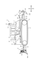
- FIG. 2 is a side view that shows a schematic diagram of the work machine 2 according to the embodiment.
- the work machine 2 includes a vehicle body 7, a traveling device 8, an excavator 9, a ripper 10, a position sensor 11, an inclination sensor 12, a three-dimensional sensor 13, and an obstacle sensor 14.
- the vehicle body 7 has an engine compartment 15.
- An engine 16 is housed in the engine compartment 15.
- the engine 16 is a drive source for the work machine 2.
- the traveling device 8 supports the vehicle body 7 and travels.
- the traveling device 8 has a pair of tracks 17.
- the work machine 2 travels as the tracks 17 rotate.
- the excavation machine 9 performs excavation work, pushing soil, or leveling work on the work target.
- the excavation machine 9 is attached to the vehicle body 7. At least a portion of the excavation machine 9 is positioned in front of the vehicle body 7.
- the excavation machine 9 has an excavation blade 18, a lift frame 19, a tilt cylinder 20, and a lift cylinder 21.
- the excavation blade 18 is positioned forward of the vehicle body 7.
- the excavation blade 18 has a cutting edge 18A.
- the lift frame 19 supports the excavation blade 18.
- One end of the lift frame 19 is connected to the back of the excavation blade 18 via a pivoting mechanism.
- the other end of the lift frame 19 is connected to the vehicle body 7 via a pivoting mechanism.
- the other end of the lift frame 19 may be connected to the traveling device 8 via a pivoting mechanism.
- the tilt cylinder 20 and the lift cylinder 21 each operate the excavation blade 18.
- the tilt cylinder 20 drives the excavation blade 18 to tilt.
- the lift cylinder 21 drives the excavation blade 18 to move up and down.
- One end of the tilt cylinder 20 is connected to the back of the excavation blade 18 via a pivot mechanism.
- the other end of the tilt cylinder 20 is connected to the upper surface of the lift frame 19.
- the tilt angle of the excavation blade 18 changes as the tilt cylinder 20 extends and retracts.
- One end of the lift cylinder 21 is connected to the lift frame 19 via a pivot mechanism.
- the other end of the lift cylinder 21 is connected to the vehicle body 7 via a pivot mechanism.
- the excavation blade 18 moves up and down as the lift cylinder 21 extends and retracts.
- the ripper work machine 10 performs ripping work including cutting or crushing the work object.
- the ripper work machine 10 is attached to the vehicle body 7. At least a portion of the ripper work machine 10 is arranged rearward of the vehicle body 7.
- the ripper work machine 10 has a shank 22, a ripper arm 23, a tilt cylinder 24, a lift cylinder 25, and a beam 26.
- the shank 22 is arranged rearward of the vehicle body 7.
- the shank 22 has a ripper point 22A.
- the ripper point 22A is provided at the tip of the shank 22.
- the ripper arm 23 supports the shank 22.
- the ripper arm 23 connects the vehicle body 7 and the shank 22.
- One end of the ripper arm 23 is connected to the rear of the vehicle body 7 via a pivot mechanism.
- the other end of the ripper arm 23 is connected to the beam 26.
- the beam 26 is rotatably connected to the ripper arm 23.
- the shank 22 is connected to the ripper arm 23 via the beam 26.
- the tilt cylinder 24 and the lift cylinder 25 each move the shank 22.
- the tilt cylinder 24 and the lift cylinder 25 are each connected to the vehicle body 7.
- the tilt cylinder 24 drives the shank 22 to tilt.
- the lift cylinder 25 drives the shank 22 to move up and down.
- One end of the tilt cylinder 24 is connected to the beam 26 via a rotating mechanism.
- the other end of the tilt cylinder 24 is connected to the rear of the vehicle body 7.
- the tilt cylinder 24 expands and contracts, changing the tilt angle of the shank 22.
- the tilt cylinder 24 moves the shank 22 in the forward and backward directions.
- One end of the lift cylinder 25 is connected to the beam 26 via a rotating mechanism.
- the other end of the lift cylinder 25 is connected to the rear of the vehicle body 7.
- the lift cylinder 25 expands and contracts, moving the shank 22 in the vertical direction.
- the lift cylinder 25 moves the shank 22 in the vertical direction.
- the ripper work machine 10 pierces the work target with the ripper point 22A. With the ripper point 22A pierced into the work target, the traveling device 8 travels, cutting or crushing the work target. While the traveling device 8 is traveling, the shank 22 may be moved in the up-down and back-and-forth directions.
- the position sensor 11 detects the position of the work machine 2.
- the position of the work machine 2 is detected using a Global Navigation Satellite System (GNSS).
- the Global Navigation Satellite System includes a Global Positioning System (GPS).
- GPS Global Positioning System
- the Global Navigation Satellite System detects the position of a global coordinate system defined by coordinate data of latitude, longitude, and altitude.
- the global coordinate system is a coordinate system fixed to the Earth.
- the position sensor 11 includes a GNSS receiver.
- the position sensor 11 detects the position of the work machine 2 in the global coordinate system.
- the position sensor 11 is arranged on the vehicle body 7.
- the tilt sensor 12 detects the inclination of the vehicle body 7.
- the tilt sensor 12 detects the inclination angle of the vehicle body 7 with respect to a horizontal plane.
- the tilt sensor 12 includes an inertial measurement unit (IMU).
- IMU inertial measurement unit
- the tilt sensor 12 is disposed on the vehicle body 7.
- the three-dimensional sensor 13 detects the three-dimensional shape of the detection target.
- the three-dimensional sensor 13 detects the three-dimensional shape of the detection target without contacting the detection target.
- the detection target of the three-dimensional sensor 13 includes the work site.
- the three-dimensional sensor 13 detects the three-dimensional shape of the work site.
- the three-dimensional shape of the work site includes the topography of the work site.
- the three-dimensional sensor 13 detects the distance to the surface of the detection target.
- the three-dimensional sensor 13 detects the three-dimensional shape of the surface of the detection target by detecting the relative distance to each of the multiple detection points on the surface of the detection target.
- the three-dimensional data indicating the three-dimensional shape of the detection target includes point cloud data consisting of multiple detection points.
- the three-dimensional data includes the relative distance and relative position between the three-dimensional sensor 13 and each of the multiple detection points defined on the detection target.
- the three-dimensional data includes height data of each of the multiple detection points.
- An example of the three-dimensional sensor 13 is a laser sensor (LIDAR: Light Detection and Ranging) that detects the detection target by emitting laser light.
- the three-dimensional sensor 13 may be a three-dimensional camera such as a stereo camera.
- the three-dimensional sensor 13 is disposed on the vehicle body 7.
- the obstacle sensor 14 detects objects present around the work machine 2.
- the obstacle sensor 14 detects obstacles to the work machine 2 present at the work site.
- the obstacle sensor 14 detects obstacles without contacting the obstacles.
- An example of the obstacle sensor 14 is a radar sensor (RADAR: Radio Detection and Ranging) that detects obstacles by emitting radio waves.
- the obstacle sensor 14 may also be an infrared sensor that detects obstacles by emitting infrared light.
- the obstacle sensor 14 is disposed on the vehicle body 7.
- the three-dimensional sensor 13 has a detection range 130.
- the three-dimensional sensor 13 detects three-dimensional data of a detection target arranged in the detection range 130.
- the three-dimensional sensor 13 includes a three-dimensional sensor 13F that detects three-dimensional data in front of the vehicle body 7, and a three-dimensional sensor 13B that detects three-dimensional data in the rear of the vehicle body 7.
- the detection range 130 of the three-dimensional sensor 13 includes a detection range 130F of the three-dimensional sensor 13F and a detection range 130B of the three-dimensional sensor 13B. At least a portion of the detection range 130F is defined forward of the excavation work machine 9. At least a portion of the detection range 130B is defined rearward of the ripper work machine 10.
- the obstacle sensor 14 has a detection range 140.
- the obstacle sensor 14 detects obstacles located within the detection range 140.
- the obstacle sensor 14 detects obstacles behind the vehicle body 7.
- the obstacle sensor 14 includes an obstacle sensor 14L located to the left of the center of the vehicle body 7 in the left-right direction, and an obstacle sensor 14R located to the right.
- the detection range 140 of the obstacle sensor 14 includes a detection range 140L of the obstacle sensor 14L and a detection range 140R of the obstacle sensor 14R. At least a portion of the detection range 140L and at least a portion of the detection range 140R are defined behind the vehicle body 7. At least a portion of the detection range 140L is defined to the left of the vehicle body 7. At least a portion of the detection range 140R is defined to the right of the vehicle body 7.
- FIG. 4 is a diagram showing a schematic example of the operation of the work machine 2 according to the embodiment.
- the work machine 2 can perform slot dozing.
- Slot dozing refers to a construction method in which the work machine 2 excavates the work object while repeatedly moving forward and backward along a slot-shaped excavation lane formed in the work object.
- the work machine 2 performs slot dozing by automatic control. As shown in FIG. 4, the work machine 2 performs slot dozing so that the current topography has a shape along the final design surface 27Z. In the example shown in FIG.
- the work machine 2 excavates the work object with the excavation machine 9 while moving forward from the excavation start point 27S so that the current topography has a shape along the first intermediate design surface 27A. After the first excavation is completed, the work machine 2 moves backward to return to the excavation start point 27S. In the second excavation, the work machine 2 excavates the work object with the excavation machine 9 while moving forward from the excavation start point 27S so that the current topography has a shape along the second intermediate design surface 27B. The work machine 2 repeatedly moves forward and backward until the current terrain is shaped along the final design surface 27Z.
- the automatic control of the work machine 2 may be semi-automatic control performed in conjunction with manual operation by an operator, or may be fully automatic control performed without manual operation.
- an operating device for manual operation may be mounted on the work machine 2 and operated by an operator on board the work machine 2.
- An operating device for manual operation may be located outside the work machine 2 and remotely operated by an operator located outside the work machine 2.
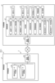
- FIG. 5 is a block diagram showing a control system 100 for the work machine 2 according to the embodiment.
- the management system 1 includes the control system 100.
- the control system 100 performs travel stop control of the work machine 2.
- the control system 100 has a control device 6, a position sensor 11, an inclination sensor 12, a three-dimensional sensor 13, an obstacle sensor 14, an alarm device 30, and a traveling device 8.
- the control device 6 has a position data acquisition unit 61, a three-dimensional data acquisition unit 62, an obstacle data acquisition unit 63, a determination unit 64, a position setting unit 65, an alarm control unit 66, a traveling control unit 67, a current terrain data creation unit 68, and a current terrain data storage unit 69.
- the position data acquisition unit 61 acquires position data indicating the current position of the work machine 2.
- the current position of the work machine 2 includes detection data from the position sensor 11.
- the position data acquisition unit 61 acquires the detection data from the position sensor 11 as position data.
- the position data acquisition unit 61 acquires posture data indicating the posture of the work machine 2.
- the posture of the work machine 2 includes detection data from the tilt sensor 12.
- the position data acquisition unit 61 acquires the detection data from the tilt sensor 12 as posture data.
- the three-dimensional data acquisition unit 62 acquires three-dimensional data indicating the three-dimensional shape of the work site where the work machine 2 is operating.
- the three-dimensional data of the work site includes detection data from the three-dimensional sensor 13.
- the three-dimensional data acquisition unit 62 acquires the detection data from the three-dimensional sensor 13 as three-dimensional data.
- the three-dimensional sensor 13 also detects objects that exist in the traveling direction of the work machine 2.
- the three-dimensional data acquisition unit 62 acquires the detection data from the three-dimensional sensor 13 that detects objects that exist in the traveling direction of the work machine 2.
- the three-dimensional sensor 13 also detects the periphery of the work machine 2.
- the three-dimensional data acquisition unit 62 acquires the detection data from the three-dimensional sensor 13 that detects the periphery of the work machine 2.
- the obstacle data acquisition unit 63 acquires obstacle data indicating obstacles present in the vicinity of the work machine 2.
- the obstacle data includes detection data from the obstacle sensor 14.
- the obstacle data acquisition unit 63 acquires the detection data from the obstacle sensor 14 as the obstacle data.
- the obstacle data may include three-dimensional data indicating the three-dimensional shape of the object detected by the three-dimensional sensor 13.
- the obstacle data acquisition unit 63 may acquire, as the obstacle data, a position determined by integrating a representative point of a parked object detected from point cloud data included in the three-dimensional data and the detection data from the obstacle sensor 14.
- the determination unit 64 determines the type of cliff that exists in the traveling direction of the work machine 2 based on the detection data of the three-dimensional sensor 13.
- the three-dimensional sensor 13 detects the three-dimensional shape of the area around the work machine 2.
- the determination unit 64 determines the type of cliff based on the three-dimensional data that indicates the three-dimensional shape of the area around the work machine 2 detected by the three-dimensional sensor 13.
- the types of cliff include upward cliffs and downward cliffs.
- the determination unit 64 determines whether or not an upward cliff exists in the traveling direction of the work machine 2 based on the detection data of the three-dimensional sensor 13.
- the determination unit 64 determines whether or not a downward cliff exists in the traveling direction of the work machine 2 based on the detection data of the three-dimensional sensor 13.
- the position setting unit 65 changes the warning range of the work machine 2 based on the type of cliff determined by the determination unit 64.
- the position setting unit 65 also changes the stopping position of the work machine 2 based on the type of cliff determined by the determination unit 64.
- the alarm control unit 66 controls the alarm device 30 based on the alarm range set by the position setting unit 65.
- the alarm device 30 is disposed, for example, in the driver's cab of the work machine 2.
- the alarm device 30 may be an audio output device that outputs an alarm sound, or a display device that displays alarm display data.
- the travel control unit 67 controls the travel control unit 67 based on the stop position set by the position setting unit 65.
- the travel control unit 67 stops the travel of the work machine 2 based on the stop position set by the position setting unit 65.
- the current terrain data creation unit 68 creates current terrain data of the work site based on the three-dimensional data acquired by the three-dimensional data acquisition unit 62, the position data indicating the current position of the work machine 2 acquired by the position data acquisition unit 61, and the attitude data indicating the attitude of the work machine 2 acquired by the position data acquisition unit 61.
- the current terrain data creation unit 68 creates current terrain data of the work site based on the detection data of the three-dimensional sensor 13, the detection data of the position sensor 11, and the detection data of the tilt sensor 12.
- the current terrain data storage unit 69 stores the current terrain data of the work site created by the current terrain data creation unit 68.
- the current terrain data storage unit 69 stores the current terrain data, time, and attribute data assigned to the current terrain data in association with each other.
- the current terrain data storage unit 69 stores the current terrain data, the time when the current terrain data was acquired, and the current position of the work machine 2 when the current terrain data was acquired in association with each other, based on the position data indicating the current position of the work machine 2 acquired by the position data acquisition unit 61.
- the management device 3 has a current terrain data creation unit 3A and a current terrain data storage unit 3B. As described above, there are multiple work machines 2 at the work site. Each of the multiple work machines 2 transmits the current terrain data stored in the current terrain data storage unit 69 to the management device 3 via the communication system 4.
- the current terrain data creation unit 3A integrates the current terrain data transmitted from each of the multiple work machines 2 to create current terrain data for the work site.
- the current terrain data storage unit 3B stores the current terrain data created by the current terrain data creation unit 3A.
- Each of the multiple work machines 2 transmits the current terrain data to the management device 3 at a predetermined time interval. Each of the multiple work machines 2 transmits the current terrain data to the management device 3, for example, every second.
- the current terrain data creation unit 3A creates current terrain data each time it receives current terrain data. Each time the current terrain data creation unit 3A creates current terrain data, the current terrain data stored in the current terrain data storage unit 3B is updated.
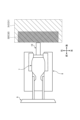
- FIG. 6 is a diagram for explaining the stored data stored in the current topography data storage unit 69 according to the embodiment.
- the three-dimensional data of the work site includes height data of each of the multiple detection points 28 defined on the surface of the topography of the work site.
- the positions of each of the multiple detection points 28 in the global coordinate system are determined based on the current position of the work machine 2 at the time the three-dimensional data is acquired, the attitude of the work machine 2, and the three-dimensional data.
- the positions of the detection points 28 may be defined in the global coordinate system, or may be defined in a predetermined coordinate system such as a local coordinate system set in the work machine 2. Time data indicating a time is assigned to each of the multiple detection points 28.
- the time indicated by the time data refers to the time when the three-dimensional data acquisition unit 62 acquires the detection point 28, or the time when the position data acquisition unit 61 acquires position data corresponding to the detection point 28.
- the time of the time data may be considered to be the time when the three-dimensional sensor 13 detects the detection point 28.
- the time data is stored in association with each of the multiple detection points 28.
- attribute data indicating an attribute is assigned to each of the multiple detection points 28.
- the attributes indicated by the attribute data refer to the attributes of the detection points 28.
- the attributes of the detection points 28 include attributes related to the topography of the work site and attributes related to obstacles present in the work site.
- the attribute data is stored in association with each of the multiple detection points 28.
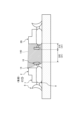
- Fig. 7 is a plan view showing a schematic diagram of the warning range 31 and the stop range 32 set in the work machine 2 according to the embodiment.
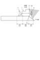
- Fig. 8 is a side view showing a schematic diagram of the warning range 31 and the stop range 32 set in the work machine 2 according to the embodiment.
- Figs. 7 and 8 each show the warning range 31A and the stop range 32A when an ascending cliff is present ahead of the advancing work machine 2.
- the warning control unit 66 activates the warning device 30.
- the stop range 32A includes a forward stop position indicating a target stop position of the advancing work machine 2.
- the stop range 32A including the forward stop position is set ahead of the excavation blade 18 of the excavation work machine 9.
- the forward stop position may be defined at the front end of the stop range 32A, may be defined at the rear end of the stop range 32A, or may be defined between the front end and the rear end of the stop range 32A.
- the determination unit 64 determines whether or not an upward cliff exists ahead of the work machine 2 based on the detection data of the three-dimensional sensor 13. As shown in FIG. 7 and FIG. 8, when the determination unit 64 determines that the type of cliff existing ahead of the work machine 2 in the traveling direction is an upward cliff, the position setting unit 65 sets the stop range 32A ahead of the work machine 2. When it is determined that an upward cliff exists ahead of the work machine 2, the travel control unit 67 controls the traveling device 8 based on the relative position between the forward stop position set ahead of the excavation blade 18 and the upward cliff.
- the travel control unit 67 stops the traveling (forward movement) of the traveling device 8 based on the relative position between the forward stop position set ahead of the excavation blade 18 and the upward cliff.
- the travel control unit 67 stops the traveling (forward movement) of the traveling device 8 before the forward stop position enters the upward cliff or so that the forward stop position coincides with the start position 33 of the upward cliff.
- FIG. 9 is a plan view showing a schematic diagram of the warning range 31 and the stop range 32 set in the work machine 2 according to the embodiment.
- FIG. 10 is a side view showing a schematic diagram of the warning range 31 and the stop range 32 set in the work machine 2 according to the embodiment.
- FIG. 9 and FIG. 10 shows the warning range 31B and the stop range 32B when a downward cliff is present in front of the advancing work machine 2.
- the warning control unit 66 activates the warning device 30.
- the stop range 32B includes a forward stop position indicating a target stop position of the advancing work machine 2.
- the stop range 32B including the forward stop position is set rearward of the excavation blade 18 of the excavation work machine 9.
- the stop range 32B including the forward stop position is set forward of the rear end of the vehicle body 7.
- the forward stop position may be defined at the front end of the stop range 32B, may be defined at the rear end of the stop range 32B, or may be defined between the front end and the rear end of the stop range 32B.
- the determination unit 64 determines whether or not a downward cliff exists ahead of the work machine 2 based on the detection data of the three-dimensional sensor 13. As shown in Figures 9 and 10, when the determination unit 64 determines that the type of cliff existing ahead in the traveling direction of the work machine 2 is a downward cliff, the position setting unit 65 sets the stop range 32B rearward of the front end of the work machine 2. The position setting unit 65 also sets the stop range 32B forward of the rear end of the work machine 2.
- the front end of the work machine 2 includes the front end of the excavation work machine 9.
- the rear end of the work machine 2 includes the rear end of the ripper work machine 10. As described above, in the embodiment, the stop range 32B is set rearward of the excavation blade 18 and forward of the rear end of the vehicle body 7.
- the travel control unit 67 determines that a downward cliff exists ahead of the work machine 2, it controls the travel device 8 based on the relative position between the forward stop position set rearward of the excavation blade 18 and the downward cliff.
- the travel control unit 67 stops the travel (forward movement) of the traveling device 8 based on the relative position of the downward cliff and a forward movement stop position set behind the excavation blade 18.
- the travel control unit 67 stops the travel (forward movement) of the traveling device 8 before the forward movement stop position enters the downward cliff or so that the forward movement stop position coincides with the start position 34 of the downward cliff.
- FIG. 11 is a plan view showing a schematic of the warning range 31 and the stop range 32 set on the work machine 2 according to the embodiment.
- FIG. 12 is a side view showing a schematic of the warning range 31 and the stop range 32 set on the work machine 2 according to the embodiment.
- Each of FIG. 11 and FIG. 12 shows the warning range 31C and the stop range 32C when an upward cliff is present behind the work machine 2 moving backwards.
- the warning control unit 66 activates the warning device 30.
- the stop range 32C includes a reverse stop position indicating a target stop position of the work machine 2 moving backwards.
- the stop range 32C including the reverse stop position is set rearward of the shank 22 of the ripper work machine 10.
- the reverse stop position may be defined at the front end of the stop range 32C, may be defined at the rear end of the stop range 32C, or may be defined between the front end and the rear end of the stop range 32C.
- the determination unit 64 determines whether or not an upward cliff exists behind the work machine 2 based on the detection data of the three-dimensional sensor 13. As shown in FIG. 11 and FIG. 12, when the determination unit 64 determines that the type of cliff existing behind the work machine 2 in the traveling direction is an upward cliff, the position setting unit 65 sets the stop range 32C behind the work machine 2. When it is determined that an upward cliff exists behind the work machine 2, the travel control unit 67 controls the traveling device 8 based on the relative position between the upward cliff and the reverse stop position set behind the shank 22. When it is determined that an upward cliff exists behind the work machine 2, the travel control unit 67 stops the traveling (reverse) of the traveling device 8 based on the relative position between the upward cliff and the reverse stop position set behind the shank 22. The travel control unit 67 stops the traveling (reverse) of the traveling device 8 before the reverse stop position enters the upward cliff or so that the reverse stop position coincides with the start position 33 of the upward cliff.
- FIG. 13 is a plan view showing a schematic of the warning range 31 and the stopping range 32 set on the work machine 2 according to the embodiment.
- FIG. 14 is a side view showing a schematic of the warning range 31 and the stopping range 32 set on the work machine 2 according to the embodiment.
- Each of FIG. 13 and FIG. 14 shows the warning range 31D and the stopping range 32D when a downward cliff is present behind the work machine 2 reversing.
- the warning control unit 66 activates the warning device 30.
- the stopping range 32D includes a reverse stop position indicating a target stop position for the work machine 2 reversing.
- the stopping range 32D including the reverse stop position is set forward of the shank 22 of the ripper work machine 10.
- the stopping range 32D including the reverse stop position is set rearward of the front end of the vehicle body 7.
- the reverse stop position may be defined at the front end of the stop range 32D, at the rear end of the stop range 32D, or between the front and rear ends of the stop range 32D.
- the determination unit 64 determines whether or not a downward cliff exists behind the work machine 2 based on the detection data of the three-dimensional sensor 13. As shown in Figures 13 and 14, when the determination unit 64 determines that the type of cliff existing behind the work machine 2 in the direction of travel is a downward cliff, the position setting unit 65 sets the stop range 32D forward of the rear end of the work machine 2. The position setting unit 65 also sets the stop range 32D rearward of the front end of the work machine 2. The rear end of the work machine 2 includes the rear end of the ripper work machine 10. The front end of the work machine 2 includes the front end of the excavation work machine 9. As described above, in the embodiment, the stop range 32D is set forward of the shank 22 and rearward of the front end of the vehicle body 7.
- the travel control unit 67 determines that a downward cliff exists behind the work machine 2, it controls the travel device 8 based on the relative position of the downward cliff and the reverse stop position set rearward of the shank 22.
- the travel control unit 67 stops the travel (reverse) of the traveling device 8 based on the relative position of the downward cliff and a reverse stop position set behind the shank 22.
- the travel control unit 67 stops the travel (reverse) of the traveling device 8 before the reverse stop position enters the downward cliff or so that the reverse stop position coincides with the start position 34 of the downward cliff.
- FIG. 15 is a plan view showing a schematic diagram of the warning range 31 and the stop range 32 set on the work machine 2 according to the embodiment.
- FIG. 16 is a side view showing a schematic diagram of the warning range 31 and the stop range 32 set on the work machine 2 according to the embodiment.
- FIG. 15 and FIG. 16 shows the warning range 31E and the stop range 32E when an object (obstacle) is present behind the work machine 2 moving in reverse.
- the object is another work machine 2B.
- the warning control unit 66 activates the warning device 30.
- the stop range 32E includes a reverse stop position indicating a target stop position of the work machine 2 moving in reverse.
- the stop range 32E including the reverse stop position is set behind the shank 22 of the ripper work machine 10.
- the reverse stop position may be defined at the front end of the stop range 32E, at the rear end of the stop range 32E, or between the front and rear ends of the stop range 32E.
- the obstacle sensor 14 detects an object (obstacle) present in the vicinity of the work machine 2.
- the determination unit 64 determines whether or not an object (obstacle) exists in the vicinity of the work machine 2 based on the detection data of the obstacle sensor 14.
- the determination unit 64 may determine whether or not an object (obstacle) exists in the vicinity of the work machine 2 based on the detection data of the obstacle sensor 14 and three-dimensional data indicating the three-dimensional shape of the detection target of the three-dimensional sensor 13.
- the determination unit 64 may determine that an object (obstacle) exists in a position obtained by integrating the representative point of the stationary object detected from the point cloud data included in the three-dimensional data and the detection data of the obstacle sensor 14.
- the determination unit 64 determines whether or not another work machine 2B exists behind the work machine 2 based on the detection data of the obstacle sensor 14. As shown in Figures 15 and 16, when the determination unit 64 determines that another work machine 2B exists behind the work machine 2, which is the traveling direction of the work machine 2, the position setting unit 65 sets the stop range 32E behind the work machine 2. When it is determined that another work machine 2B is present behind the work machine 2, the travel control unit 67 controls the travel device 8 based on the relative position between the other work machine 2B and the reverse stop position set behind the shank 22.
- the travel control unit 67 stops the travel (reverse) of the travel device 8 based on the relative position between the other work machine 2B and the reverse stop position set behind the shank 22.
- the travel control unit 67 stops the travel (reverse) of the travel device 8 before the reverse stop position enters the other work machine 2B.
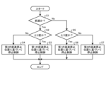
- Fig. 17 is a flowchart showing a method of controlling the work machine 2 according to the embodiment.
- the determination unit 64 determines whether or not the work machine 2 is moving forward (step S1). When it is determined in step S1 that the work machine 2 is moving forward (step S1: Yes), the determination unit 64 determines whether or not an upward cliff exists ahead of the work machine 2 based on the detection data of the three-dimensional sensor 13F (step S2). When it is determined in step S2 that an upward cliff exists (step S2: Yes), the traveling control unit 67 stops the forward movement of the work machine 2 based on the first forward movement stop position included in the stop range 32A described with reference to Figs. 7 and 8.
- step S2 When it is determined in step S2 that a downward cliff exists (step S2: No), the traveling control unit 67 stops the forward movement of the work machine 2 based on the second forward movement stop position included in the stop range 32B described with reference to Figs. 9 and 10.
- step S5 determines whether or not an upward cliff exists behind the work machine 2 based on the detection data of the three-dimensional sensor 13B (step S5). If it is determined in step S5 that an upward cliff exists (step S5: Yes), the travel control unit 67 stops the reverse movement of the work machine 2 based on the first reverse stop position included in the stop range 32C described with reference to Figures 11 and 12. If it is determined in step S5 that a downward cliff exists (step S5: No), the travel control unit 67 stops the reverse movement of the work machine 2 based on the second reverse stop position included in the stop range 32D described with reference to Figures 13 and 14.
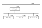
- FIG. 18 is a block diagram showing a computer system 1000 according to an embodiment.
- the computer system 1000 has a processor 1001 such as a CPU (Central Processing Unit), a main memory 1002 including a non-volatile memory such as a ROM (Read Only Memory) and a volatile memory such as a RAM (Random Access Memory), a storage 1003, and an interface 1004 including an input/output circuit.
- the functions of the above-mentioned management device 3 and control device 6 are stored in the storage 1003 as computer programs.
- the processor 1001 reads the computer program from the storage 1003, expands it in the main memory 1002, and executes the above-mentioned processing according to the program.
- the computer program may be distributed to the computer system 1000 via a network.
- the computer system 1000 or computer program, according to the above-described embodiment, can acquire detection data from a three-dimensional sensor 13 that detects objects present in the traveling direction of the work machine 2, determine the type of cliff present in the traveling direction based on the detection data from the three-dimensional sensor 13, change the stopping position of the work machine 2 based on the type of cliff, and stop the traveling of the work machine 2 based on the stopping position.
- the control system 100 for the work machine 2 includes a three-dimensional data acquisition unit 62 that acquires detection data from the three-dimensional sensor 13 that detects objects present in the traveling direction of the work machine 2, a determination unit 64 that determines the type of cliff present in the traveling direction based on the detection data from the three-dimensional sensor 13, a position setting unit 65 that changes the stopping position of the work machine 2 based on the type of cliff, and a travel control unit 67 that stops the traveling of the work machine 2 based on the stopping position.
- the traveling distance of the work machine 2 will be shortened, which may decrease the operability of the work machine 2. If the work machine 2 stops at a position beyond the start position 33 of the upward cliff, the work machine 2 may come into contact with the upward cliff. If the work machine 2 stops at a position away from the start position 34 of the downward cliff, the traveling distance of the work machine 2 will be shortened, which may decrease the operability of the work machine 2. There is a possibility that the work machine 2 may fall off the downward cliff if it stops at a position far beyond the start position 34 of the downward cliff. By appropriately setting the stopping position according to the type of cliff, it is possible to stop the work machine 2 at an appropriate position while suppressing a decrease in the workability of the work machine 2.
- the current terrain data creation unit 68 may create current terrain data of the work site based on at least the three-dimensional data acquired by the three-dimensional data acquisition unit 62.
- the current terrain data creation unit 68 may also create current terrain data of the work site based on at least position data indicating the current position of the work machine 2 acquired by the position data acquisition unit 61.
- the determination unit 64 may determine the type of cliff that exists in the traveling direction of the work machine 2 based on the current terrain data of the work site created by the current terrain data creation unit 68.
- the determination unit 64 may determine whether or not an uphill cliff exists in the traveling direction of the work machine 2 based on the current terrain data of the work site created by the current terrain data creation unit 68.
- the determination unit 64 may determine whether or not a downhill cliff exists in the traveling direction of the work machine 2 based on the current terrain data of the work site created by the current terrain data creation unit 68.
- At least some of the functions of the control device 6 may be provided in the management device 3. At least some of the functions of the management device 3 may be provided in the control device 6.
- each of the position data acquisition unit 61, the three-dimensional data acquisition unit 62, the obstacle data acquisition unit 63, the determination unit 64, the position setting unit 65, the warning control unit 66, the driving control unit 67, the current terrain data creation unit 68, and the current terrain data storage unit 69 may be configured as separate hardware.
- the work machine 2 is a bulldozer.
- the work machine 2 may be another work machine such as a hydraulic excavator, a wheel loader, or a motor grader.
Landscapes
- Engineering & Computer Science (AREA)
- Mining & Mineral Resources (AREA)
- Civil Engineering (AREA)
- General Engineering & Computer Science (AREA)
- Structural Engineering (AREA)
- Operation Control Of Excavators (AREA)
- Control Of Position, Course, Altitude, Or Attitude Of Moving Bodies (AREA)
- Component Parts Of Construction Machinery (AREA)
Abstract
Description
図1は、実施形態に係る作業現場の管理システム1を模式的に示す図である。実施形態において、作業現場は、鉱山である。鉱山とは、鉱物を採掘する場所又は事業所をいう。鉱山として、金属を採掘する金属鉱山、石灰石を採掘する非金属鉱山、又は石炭を採掘する石炭鉱山が例示される。作業現場において、複数の作業機械2が稼働する。実施形態において、作業機械2は、ブルドーザである。作業機械2は、作業現場において所定の作業を実施する。作業機械2が実施する作業として、掘削作業、押土作業、及び整地作業が例示される。
図2は、実施形態に係る作業機械2を模式的に示す側面図である。図2に示すように、作業機械2は、車体7と、走行装置8と、掘削作業機9と、リッパ作業機10と、位置センサ11と、傾斜センサ12と、3次元センサ13と、障害物センサ14とを備える。車体7は、エンジン室15を有する。エンジン室15にエンジン16が収容される。エンジン16は、作業機械2の駆動源である。走行装置8は、車体7を支持して走行する。走行装置8は、一対の履帯17を有する。履帯17が回転することにより、作業機械2が走行する。
図4は、実施形態に係る作業機械2の動作の一例を模式的に示す図である。実施形態において、作業機械2は、スロットドージング(slot dozing)を実施することができる。スロットドージングとは、作業対象に形成されたスロット状の掘削レーンに沿って作業機械2が前進と後進とを繰り返しながら作業対象を掘削する施工法をいう。実施形態において、作業機械2は、自動制御によりスロットドージングを実施する。図4に示すように、作業機械2は、現況地形が最終設計面27Zに沿った形状になるように、スロットドージングする。図4に示す例において、作業機械2は、第1回目の掘削において、現況地形が第1中間設計面27Aに沿った形状になるように、掘削開始点27Sから前進しながら掘削作業機9で作業対象を掘削する。第1回目の掘削が終了した後、作業機械2は、掘削開始点27Sに戻るために後進する。作業機械2は、第2回目の掘削において、現況地形が第2中間設計面27Bに沿った形状になるように、掘削開始点27Sから前進しながら掘削作業機9で作業対象を掘削する。作業機械2は、現況地形が最終設計面27Zに沿って形状になるまで、前進と後進とを繰り返す。
図5は、実施形態に係る作業機械2の制御システム100を示すブロック図である。管理システム1は、制御システム100を含む。制御システム100は、作業機械2の走行停止制御を実施する。制御システム100は、制御装置6と、位置センサ11と、傾斜センサ12と、3次元センサ13と、障害物センサ14と、警報装置30と、走行装置8とを有する。制御装置6は、位置データ取得部61と、3次元データ取得部62と、障害物データ取得部63と、判定部64と、位置設定部65と、警報制御部66と、走行制御部67と、現況地形データ作成部68と、現況地形データ記憶部69とを有する。
図6は、実施形態に係る現況地形データ記憶部69に記憶される記憶データを説明するための図である。図6に示すように、作業現場の3次元データは、作業現場の地形の表面に規定される複数の検出点28のそれぞれの高さデータを含む。3次元データが取得されたときの作業機械2の現況位置、作業機械2の姿勢、及び3次元データに基づいて、グローバル座標系における複数の検出点28のそれぞれの位置が定められる。なお、検出点28の位置は、グローバル座標系において規定されてもよいし、作業機械2に設定されたローカル座標系のような所定の座標系において規定されてもよい。複数の検出点28のそれぞれに、時刻を示す時刻データが付与される。時刻データが示す時刻とは、3次元データ取得部62が検出点28を取得した時刻、又は位置データ取得部61が検出点28に対応する位置データを取得した時刻をいう。なお、時刻データの時刻は、3次元センサ13が検出点28を検出した時刻とみなされてもよい。時刻データは、複数の検出点28のそれぞれに対応付けて記憶される。また、複数の検出点28のそれぞれに、属性を示す属性データが付与される。属性データが示す属性とは、検出点28の属性をいう。検出点28の属性は、作業現場の地形に係る属性及び作業現場に存在する障害物に係る属性を含む。属性データは、複数の検出点28のそれぞれに対応付けて記憶される。
図7は、実施形態に係る作業機械2に設定される警報範囲31及び停止範囲32を模式的に示す平面図である。図8は、実施形態に係る作業機械2に設定される警報範囲31及び停止範囲32を模式的に示す側面図である。図7及び図8のそれぞれは、前進する作業機械2の前方に上り崖が存在するときの警報範囲31A及び停止範囲32Aを示す。上り崖に向かって前進する作業機械2の警報範囲31Aに上り崖が配置されると、警報制御部66は、警報装置30を作動させる。停止範囲32Aは、前進する作業機械2の目標停止位置を示す前進停止位置を含む。前進停止位置を含む停止範囲32Aは、掘削作業機9の掘削ブレード18よりも前方に設定される。前進停止位置は、停止範囲32Aの前端部に規定されてもよいし、停止範囲32Aの後端部に規定されてもよいし、停止範囲32Aの前端部と後端部との間に規定されてもよい。上り崖に向かって前進する作業機械2の停止範囲32Aに上り崖が配置されると、走行制御部67は、走行装置8を制御する。走行制御部67は、作業機械2が上り崖に接触しないように、作業機械2の走行を停止させる。
図17は、実施形態に係る作業機械2の制御方法を示すフローチャートである。判定部64は、作業機械2が前進しているか否かを判定する(ステップS1)。ステップS1において、作業機械2が前進していると判定した場合(ステップS1:Yes)、判定部64は、3次元センサ13Fの検出データに基づいて、作業機械2の前方に上り崖が存在するか否かを判定する(ステップS2)。ステップS2において、上り崖が存在すると判定された場合(ステップS2:Yes)、走行制御部67は、図7及び図8を参照して説明した停止範囲32Aに含まれる第1の前進停止位置に基づいて、作業機械2の前進を停止させる。ステップS2において、下り崖が存在すると判定された場合(ステップS2:No)、走行制御部67は、図9及び図10を参照して説明した停止範囲32Bに含まれる第2の前進停止位置に基づいて、作業機械2の前進を停止させる。
図18は、実施形態に係るコンピュータシステム1000を示すブロック図である。上述の管理装置3及び制御装置6のそれぞれは、コンピュータシステム1000を含む。コンピュータシステム1000は、CPU(Central Processing Unit)のようなプロセッサ1001と、ROM(Read Only Memory)のような不揮発性メモリ及びRAM(Random Access Memory)のような揮発性メモリを含むメインメモリ1002と、ストレージ1003と、入出力回路を含むインターフェース1004とを有する。上述の管理装置3及び制御装置6のそれぞれの機能は、コンピュータプログラムとしてストレージ1003に記憶されている。プロセッサ1001は、コンピュータプログラムをストレージ1003から読み出してメインメモリ1002に展開し、プログラムに従って上述の処理を実行する。なお、コンピュータプログラムは、ネットワークを介してコンピュータシステム1000に配信されてもよい。
以上説明したように、実施形態に係る作業機械2の制御システム100は、作業機械2の進行方向に存在する物体を検出する3次元センサ13の検出データを取得する3次元データ取得部62と、3次元センサ13の検出データに基づいて、進行方向に存在する崖の種類を判定する判定部64と、崖の種類に基づいて、作業機械2の停止位置を変更する位置設定部65と、停止位置に基づいて、作業機械2の走行を停止させる走行制御部67と、を備える。これにより、上り崖及び下り崖を含む複数種類の崖が存在する作業現場において、作業機械2の走行が適正に停止される。上り崖の開始位置33から離れた位置で停止してしまうと、作業機械2の走行距離が短くなるため、作業機械2の作業性が低下する可能性がある。上り崖の開始位置33を超えた位置で停止してしまうと、作業機械2が上り崖に接触してしまう可能性がある。下り崖の開始位置34から離れた位置で停止してしまうと、作業機械2の走行距離が短くなるため、作業機械2の作業性が低下する可能性がある。下り崖の開始位置34を大きく超えた位置で停止してしまうと、作業機械2が下り崖に落ちてしまう可能性がある。崖の種類に応じた停止位置が適正に設定されることにより、作業機械2の作業性の低下を抑制しつつ、作業機械2を適正な位置で停止させることができる。
上述の実施形態において、現況地形データ作成部68は、少なくとも3次元データ取得部62により取得された3次元データに基づいて、作業現場の現況地形データを作成してもよい。また、現況地形データ作成部68は、少なくとも位置データ取得部61により取得された作業機械2の現況位置を示す位置データに基づいて、作業現場の現況地形データを作成してもよい。
Claims (9)
- 作業機械の進行方向に存在する物体を検出する第1センサの検出データを取得する第1検出データ取得部と、
前記第1センサの検出データに基づいて、前記進行方向に存在する崖の種類を判定する判定部と、
前記崖の種類に基づいて、前記作業機械の停止位置を変更する位置設定部と、
前記停止位置に基づいて、前記作業機械の走行を停止させる走行制御部と、を備える、
作業機械の制御システム。 - 前記崖の種類が上り崖であると判定された場合、前記位置設定部は、前記作業機械よりも前記進行方向側に前記停止位置を設定する、
請求項1に記載の作業機械の制御システム。 - 前記走行制御部は、前記停止位置が前記上り崖に進入する前に又は前記停止位置が前記上り崖の開始位置に一致するように、前記作業機械の走行を停止させる、
請求項2に記載の作業機械の制御システム。 - 前記崖の種類が下り崖であると判定された場合、前記位置設定部は、前記進行方向側の前記作業機械の端部よりも前記進行方向とは逆方向側に前記停止位置を設定する、
請求項1に記載の作業機械の制御システム。 - 前記位置設定部は、前記逆方向側の前記作業機械の端部よりも前記進行方向側に前記停止位置を設定する、
請求項4に記載の作業機械の制御システム。 - 前記走行制御部は、前記停止位置が前記下り崖に進入する前に又は前記停止位置が前記下り崖の開始位置に一致するように、前記作業機械の走行を停止させる、
請求項5に記載の作業機械の制御システム。 - 前記第1センサは、前記作業機械の周辺の3次元形状を検出し、
前記判定部は、前記3次元形状を示す3次元データに基づいて、前記崖の種類を判定する、
請求項1に記載の作業機械の制御システム。 - 前記作業機械の周辺に存在する物体を検出する第2センサの検出データを取得する第2検出データ取得部を備え、
前記判定部は、前記第2センサの検出データに基づいて、前記作業機械の周辺に障害物が存在するか否かを判定する、
請求項1に記載の作業機械の制御システム。 - 作業機械の進行方向に存在する物体を検出する第1センサの検出データを取得することと、
前記第1センサの検出データに基づいて、前記進行方向に存在する崖の種類を判定することと、
前記崖の種類に基づいて、前記作業機械の停止位置を変更することと、
前記停止位置に基づいて、前記作業機械の走行を停止させることと、を含む、
作業機械の制御方法。
Priority Applications (3)
| Application Number | Priority Date | Filing Date | Title |
|---|---|---|---|
| AU2023352163A AU2023352163A1 (en) | 2022-09-30 | 2023-09-04 | Control system for work machine and control method for work machine |
| CA3262722A CA3262722A1 (en) | 2022-09-30 | 2023-09-04 | CONTROL SYSTEM AND METHOD FOR WORK MACHINE |
| US18/994,243 US20260015832A1 (en) | 2022-09-30 | 2023-09-04 | Control system for work machine and control method for work machine |
Applications Claiming Priority (2)
| Application Number | Priority Date | Filing Date | Title |
|---|---|---|---|
| JP2022158692A JP2024052162A (ja) | 2022-09-30 | 2022-09-30 | 作業機械の制御システム及び作業機械の制御方法 |
| JP2022-158692 | 2022-09-30 |
Publications (1)
| Publication Number | Publication Date |
|---|---|
| WO2024070520A1 true WO2024070520A1 (ja) | 2024-04-04 |
Family
ID=90477280
Family Applications (1)
| Application Number | Title | Priority Date | Filing Date |
|---|---|---|---|
| PCT/JP2023/032267 Ceased WO2024070520A1 (ja) | 2022-09-30 | 2023-09-04 | 作業機械の制御システム及び作業機械の制御方法 |
Country Status (5)
| Country | Link |
|---|---|
| US (1) | US20260015832A1 (ja) |
| JP (1) | JP2024052162A (ja) |
| AU (1) | AU2023352163A1 (ja) |
| CA (1) | CA3262722A1 (ja) |
| WO (1) | WO2024070520A1 (ja) |
Citations (6)
| Publication number | Priority date | Publication date | Assignee | Title |
|---|---|---|---|---|
| JPS4894501U (ja) * | 1972-02-15 | 1973-11-12 | ||
| JPH04277229A (ja) * | 1991-02-28 | 1992-10-02 | Komatsu Ltd | 衝撃リッパの故障診断方法 |
| JPH11222882A (ja) * | 1998-02-05 | 1999-08-17 | Komatsu Ltd | 危険領域監視装置 |
| JP2014006577A (ja) * | 2012-06-21 | 2014-01-16 | Hitachi Constr Mach Co Ltd | 運搬機械の停止位置判定装置およびこの装置を備えた積込機械 |
| JP2018043599A (ja) * | 2016-09-13 | 2018-03-22 | 日立建機株式会社 | 鉱山用作業機械及びその後方監視方法 |
| JP2021054307A (ja) * | 2019-09-30 | 2021-04-08 | 株式会社小松製作所 | 作業機械および作業機械の制御方法 |
-
2022
- 2022-09-30 JP JP2022158692A patent/JP2024052162A/ja active Pending
-
2023
- 2023-09-04 WO PCT/JP2023/032267 patent/WO2024070520A1/ja not_active Ceased
- 2023-09-04 CA CA3262722A patent/CA3262722A1/en active Pending
- 2023-09-04 AU AU2023352163A patent/AU2023352163A1/en active Pending
- 2023-09-04 US US18/994,243 patent/US20260015832A1/en active Pending
Patent Citations (6)
| Publication number | Priority date | Publication date | Assignee | Title |
|---|---|---|---|---|
| JPS4894501U (ja) * | 1972-02-15 | 1973-11-12 | ||
| JPH04277229A (ja) * | 1991-02-28 | 1992-10-02 | Komatsu Ltd | 衝撃リッパの故障診断方法 |
| JPH11222882A (ja) * | 1998-02-05 | 1999-08-17 | Komatsu Ltd | 危険領域監視装置 |
| JP2014006577A (ja) * | 2012-06-21 | 2014-01-16 | Hitachi Constr Mach Co Ltd | 運搬機械の停止位置判定装置およびこの装置を備えた積込機械 |
| JP2018043599A (ja) * | 2016-09-13 | 2018-03-22 | 日立建機株式会社 | 鉱山用作業機械及びその後方監視方法 |
| JP2021054307A (ja) * | 2019-09-30 | 2021-04-08 | 株式会社小松製作所 | 作業機械および作業機械の制御方法 |
Also Published As
| Publication number | Publication date |
|---|---|
| JP2024052162A (ja) | 2024-04-11 |
| AU2023352163A1 (en) | 2025-01-30 |
| US20260015832A1 (en) | 2026-01-15 |
| CA3262722A1 (en) | 2025-06-12 |
Similar Documents
| Publication | Publication Date | Title |
|---|---|---|
| CN112424427B (zh) | 作业机械的控制装置及控制方法 | |
| US12584297B2 (en) | Method and system of controlling a display device on a work machine having grade control | |
| US9945100B2 (en) | Positioning system and method for determining location of machine | |
| JPWO2019187192A1 (ja) | 作業機械の制御システム、方法、及び作業機械 | |
| JP7169760B2 (ja) | 作業車両の制御システム、方法、及び作業車両 | |
| WO2023228883A1 (ja) | 作業機械の表示システム、作業機械の遠隔操作システム、作業機械、及び作業機械の表示方法 | |
| WO2024070557A1 (ja) | 作業現場の検出システム及び作業現場の検出方法 | |
| US20230383497A1 (en) | Work machine with an adaptive control system and method for grade control | |
| WO2024101146A1 (ja) | 作業現場の表示システム及び作業現場の表示方法 | |
| WO2024070520A1 (ja) | 作業機械の制御システム及び作業機械の制御方法 | |
| WO2024070519A1 (ja) | 作業機械の制御システム及び作業機械の制御方法 | |
| WO2024070558A1 (ja) | 作業現場の検出システム及び作業現場の検出方法 | |
| WO2024101147A1 (ja) | 作業現場の判定システム及び作業現場の判定方法 | |
| WO2024101391A1 (ja) | 作業現場の現況地形データ作成システム及び作業現場の現況地形データ作成方法 | |
| CA3263358A1 (en) | Detection system for work site and detection method for work site | |
| JP2024070512A (ja) | 作業機械の校正システム及び作業機械の校正方法 | |
| US12523004B2 (en) | Systems and methods for determining poor implement penetration | |
| WO2024143089A1 (ja) | 作業現場の管理システム及び作業現場の管理方法 |
Legal Events
| Date | Code | Title | Description |
|---|---|---|---|
| 121 | Ep: the epo has been informed by wipo that ep was designated in this application |
Ref document number: 23871760 Country of ref document: EP Kind code of ref document: A1 |
|
| WWE | Wipo information: entry into national phase |
Ref document number: 18994243 Country of ref document: US |
|
| WWE | Wipo information: entry into national phase |
Ref document number: AU2023352163 Country of ref document: AU |
|
| ENP | Entry into the national phase |
Ref document number: 2023352163 Country of ref document: AU Date of ref document: 20230904 Kind code of ref document: A |
|
| NENP | Non-entry into the national phase |
Ref country code: DE |
|
| 122 | Ep: pct application non-entry in european phase |
Ref document number: 23871760 Country of ref document: EP Kind code of ref document: A1 |
|
| WWP | Wipo information: published in national office |
Ref document number: 18994243 Country of ref document: US |