WO2024070466A1 - 記録媒体およびホスト機器 - Google Patents
記録媒体およびホスト機器 Download PDFInfo
- Publication number
- WO2024070466A1 WO2024070466A1 PCT/JP2023/031731 JP2023031731W WO2024070466A1 WO 2024070466 A1 WO2024070466 A1 WO 2024070466A1 JP 2023031731 W JP2023031731 W JP 2023031731W WO 2024070466 A1 WO2024070466 A1 WO 2024070466A1
- Authority
- WO
- WIPO (PCT)
- Prior art keywords
- temperature
- recording medium
- host device
- threshold
- guaranteed speed
- Prior art date
- Legal status (The legal status is an assumption and is not a legal conclusion. Google has not performed a legal analysis and makes no representation as to the accuracy of the status listed.)
- Ceased
Links
Images




Classifications
-
- G—PHYSICS
- G06—COMPUTING OR CALCULATING; COUNTING
- G06F—ELECTRIC DIGITAL DATA PROCESSING
- G06F1/00—Details not covered by groups G06F3/00 - G06F13/00 and G06F21/00
- G06F1/26—Power supply means, e.g. regulation thereof
- G06F1/32—Means for saving power
- G06F1/3203—Power management, i.e. event-based initiation of a power-saving mode
- G06F1/3234—Power saving characterised by the action undertaken
- G06F1/324—Power saving characterised by the action undertaken by lowering clock frequency
-
- G—PHYSICS
- G06—COMPUTING OR CALCULATING; COUNTING
- G06F—ELECTRIC DIGITAL DATA PROCESSING
- G06F1/00—Details not covered by groups G06F3/00 - G06F13/00 and G06F21/00
- G06F1/16—Constructional details or arrangements
- G06F1/20—Cooling means
- G06F1/206—Cooling means comprising thermal management
-
- G—PHYSICS
- G06—COMPUTING OR CALCULATING; COUNTING
- G06F—ELECTRIC DIGITAL DATA PROCESSING
- G06F1/00—Details not covered by groups G06F3/00 - G06F13/00 and G06F21/00
- G06F1/26—Power supply means, e.g. regulation thereof
- G06F1/32—Means for saving power
- G06F1/3203—Power management, i.e. event-based initiation of a power-saving mode
- G06F1/3206—Monitoring of events, devices or parameters that trigger a change in power modality
- G06F1/3215—Monitoring of peripheral devices
- G06F1/3225—Monitoring of peripheral devices of memory devices
-
- G—PHYSICS
- G06—COMPUTING OR CALCULATING; COUNTING
- G06F—ELECTRIC DIGITAL DATA PROCESSING
- G06F12/00—Accessing, addressing or allocating within memory systems or architectures
- G06F12/02—Addressing or allocation; Relocation
- G06F12/06—Addressing a physical block of locations, e.g. base addressing, module addressing, memory dedication
-
- G—PHYSICS
- G11—INFORMATION STORAGE
- G11C—STATIC STORES
- G11C7/00—Arrangements for writing information into, or reading information out from, a digital store
- G11C7/04—Arrangements for writing information into, or reading information out from, a digital store with means for avoiding disturbances due to temperature effects
Definitions
- This disclosure relates to a recording device that accesses a recording medium, control of the recording medium, and the recording medium.
- Patent Document 1 discloses a recording device capable of setting the temperature at which a recording medium's functions are restricted.
- This recording device has a control means for setting the temperature threshold at which the functions are restricted to a value within a range that can be set on the recording medium, and the control means switches between a first setting that sets the temperature threshold at which the functions are restricted on the recording medium to the recording medium default value, and a second setting that sets the temperature threshold at which the functions are restricted on the recording medium to a value greater than the default value, depending on whether the device is in playback mode or video recording mode.
- This disclosure provides a recording medium and host device that sets a thermal throttling threshold that takes into account temperature rise due to heat generation in the recording medium, suppresses thermal throttling, and enables writing and reading at a guaranteed speed.
- the recording medium in this disclosure is a recording medium connected to a host device, and includes a memory, a control unit that controls the memory, and an interface unit that communicates with the host device, the interface unit transmits setting information including an elevated temperature that is the temperature difference between the surface and the interior of the recording medium, receives a thermal throttling threshold temperature from the host device, and the control unit controls operation based on the threshold temperature.
- the host device in this disclosure is a host device that is connected to a recording medium and includes a control unit, and the control unit receives setting information including an elevated temperature, which is the temperature difference between the surface and the interior of the recording medium, calculates a threshold temperature based on the setting information and a convergence temperature, which is the surface temperature of the recording medium that can be controlled when the recording medium is operated continuously at a guaranteed speed, and transmits the calculated threshold temperature to the recording medium.
- the recording medium in this disclosure is a recording medium connected to a host device, and includes a memory, a control unit that controls the memory, and an interface unit that communicates with the host device, the interface unit receives command information including a convergence temperature, which is a temperature that can be controlled when the host device is operated continuously, the control unit transmits setting information including a threshold temperature calculated based on the convergence temperature and an elevated temperature, which is the temperature difference between the surface and the interior of the recording medium, receives a thermal throttling threshold temperature from the host device, and the control unit controls operation based on the thermal throttling threshold temperature.
- a convergence temperature which is a temperature that can be controlled when the host device is operated continuously
- the control unit transmits setting information including a threshold temperature calculated based on the convergence temperature and an elevated temperature, which is the temperature difference between the surface and the interior of the recording medium
- receives a thermal throttling threshold temperature from the host device receives a thermal throttling threshold temperature from the host device, and the control unit controls operation based on
- the host device in this disclosure is a host device that is connected to a recording medium and includes a control unit, and the control unit transmits command information including a convergence temperature, which is a temperature that can be controlled when the recording medium is operated continuously, receives setting information including a threshold temperature calculated by the recording medium based on the convergence temperature and an elevated temperature, which is the temperature difference between the surface and the interior of the recording medium, and transmits the threshold temperature included in the setting information to the recording medium as a thermal throttling threshold temperature.
- a convergence temperature which is a temperature that can be controlled when the recording medium is operated continuously
- the recording medium in this disclosure is a recording medium connected to a host device, and includes a memory, a control unit that controls the memory, and an interface unit that communicates with the host device, the interface unit transmits setting information including the relationship between a thermal throttling threshold and a guaranteed speed, and the relationship between a convergence temperature, the guaranteed speed, and the internal temperature of the recording medium, receives a thermal throttling threshold temperature from the host device, and the control unit controls operation based on the threshold temperature.
- the host device in this disclosure is a host device that is connected to a recording medium and includes a control unit, and the control unit receives setting information including the relationship between the thermal throttling threshold and the guaranteed speed held by the recording medium, and the relationship between the convergence temperature, the guaranteed speed, and the internal temperature of the recording medium, calculates a thermal throttling threshold temperature and selection information that selects one of a plurality of thermal throttling thresholds from the relationship between the thermal throttling threshold and the guaranteed speed, and the relationship between the convergence temperature, the guaranteed speed, and the internal temperature of the recording medium, and transmits the selection information and the threshold temperature to the recording medium.
- the thermal throttling threshold temperature is set taking into account the temperature rise caused by heat generation in the recording medium, suppressing thermal throttling and enabling writing and reading at guaranteed speeds.
- FIG. 1 is a schematic diagram showing a memory card and a host device according to first and second embodiments.
- FIG. 1 is a sequence diagram for inquiring about the threshold temperature of thermal throttling in the first embodiment.
- FIG. 13 is a diagram showing the relationship between TMT1, TMT2 and the guaranteed speed in the second embodiment.
- FIG. 13 is a diagram showing the relationship between the card surface temperature, the access speed, and the card internal temperature in the second embodiment.
- FIG. 13 is a diagram showing temperature changes and threshold values during continuous operation at 400 MByte/sec in the second embodiment.
- FIG. 13 is a diagram showing temperature changes and threshold values during continuous operation at 600 MByte/sec in the second embodiment.
- FIG. 1 is a schematic diagram showing a memory card according to a first embodiment and a connector mounted on a board of a host device.
- the board 105 of the host device 100 is equipped with a connector 103 into which the memory card 101 can be inserted and removed.
- the connector 103 is equipped with a temperature sensor 104.
- the temperature sensor 104 is designed and arranged so that it can measure the surface temperature (case temperature) of the memory card 101.
- the board 105 is also equipped with a control unit capable of sending and receiving electrical signals.
- the SoC (System On Chip) 106 is an example of a control unit.
- the SoC 106 is connected to the connector 103 by a signal line, and can transmit electrical signals from the SoC 106 to the connector 103. Furthermore, temperature information measured by the temperature sensor 104 provided in the connector 103 is notified to the SoC 106 via the signal line.
- the SoC 106 is connected to the fan 102 by a signal line, and can transmit electrical signals from the SoC 106 to the fan 102.
- the fan 102 changes its operation ON/OFF, rotation speed, etc. according to electrical signals from the SoC 106.
- the host device 100 requires a dynamic random access memory (DRAM) and other peripheral components, but these are omitted as they are not directly related to the contents of this disclosure.
- DRAM dynamic random access memory
- Memory card 101 has a built-in controller 108 and a NAND FLASH 109, which is a non-volatile memory. Controller 108 is connected to NAND FLASH 109. Controller 108 has built-in interface unit 110, control unit 111, and temperature sensor 107. Control unit 111 is connected to interface unit 110 and temperature sensor 107.
- the interface unit 110 receives commands from the SoC 106 and notifies the control unit 111.
- the control unit 111 processes the command, generates response information (setting information), and passes it to the interface unit 110.
- the interface unit 110 returns the response information to the SoC 106.
- the control unit 111 When the interface unit 110 receives a write command, the control unit 111 writes the write data received from the SoC 106 to the NAND FLASH 109 (write command processing). When the interface unit 110 receives a read command, the control unit 111 reads the data from the NAND FLASH 109 and sends it to the SoC 106 (read command processing). When the interface unit 110 receives an erase command, the control unit 111 erases the corresponding data based on the address included in the received command (erase command processing).
- the control unit 111 can read the temperature inside the card measured by the temperature sensor 107.
- the temperature sensor 107 may be built into the NAND FLASH 109, or may be built into the memory card 101 as a single component. Regardless of the implementation, the control unit 111 can read the measurement results of the temperature sensor 107.
- Figure 1 shows the memory card 101 inserted into the connector 103.
- the memory card 101 When the memory card 101 is inserted into the connector 103 mounted on the board 105 of the host device 100, commands in the form of electrical signals from the SoC 106 are received by the memory card 101 via the connector 103.
- the memory card 101 processes the command and returns response information.
- the memory card 101 processes write commands, read commands, erase commands, etc.
- the SoC 106 can obtain temperature information measured by the temperature sensor 107 built into the memory card 101 as response information to a command from the SoC 106 to the memory card 101.
- the temperature sensor 104 is installed in a position where it can measure the surface temperature of the memory card 101 when the memory card 101 is inserted.
- the temperature sensor 104 in Figure 1 is depicted as measuring the surface of the memory card 101, but it may also be installed to measure the back side of the memory card 101, and multiple temperature sensors may be installed to measure the surface temperature of the memory card 101.
- Memory card 101 has a minimum speed guarantee function. This function guarantees that if host device 100 accesses memory card 101 according to a certain procedure, writing and reading operations will be performed at a guaranteed speed or faster. This guaranteed speed is a value specific to memory card 101, and SoC 106 can obtain it as response information to a command from SoC 106 to memory card 101.
- the memory card 101 also has a thermal throttling function. This function restricts functionality and suppresses heat generation when a certain threshold temperature is exceeded.
- the memory card 101 can set multiple threshold temperatures at which thermal throttling is activated. For example, the two threshold temperatures are TMT1 (Thermal Management Temperature 1) and TMT2 (Thermal Management Temperature 2), and TMT1 is set to a threshold temperature lower than TMT2 (TMT1 ⁇ TMT2).
- the control unit 111 acquires the temperature inside the card from the temperature sensor 107.
- the control unit 111 compares the acquired temperature inside the card with each of the threshold temperatures TMT1 and TMT2. If the temperature inside the card does not exceed the threshold temperature TMT1, the control unit 111 does not activate thermal throttling. If the temperature inside the card exceeds the threshold temperature TMT1, the control unit 111 activates thermal throttling (weak thermal throttling) by means such as slowing down the internal operating clock. Furthermore, if the temperature exceeds the threshold temperature TMT2, the control unit 111 activates thermal throttling (strong thermal throttling) by means such as further slowing down the speed of the internal operating clock.
- the memory card 101 holds a Maximum Thermal Management Temperature (MXTMT) that indicates the maximum value that can be set for the threshold temperature TMT1 and the threshold temperature TMT2.
- MXTMT Maximum Thermal Management Temperature
- This maximum value MXTMT is a value specific to the memory card 101, and can be obtained by the SoC 106 as response information to a command sent from the SoC 106 to the memory card 101.
- threshold temperatures TMT1, TMT2, and maximum value MXTMT refer to the NVMe standard (NVM Express Revision 1.3 May 1, 2017).
- the operation of the host device 100 and memory card 101 configured as above will be described below.
- the host device 100 performs the operation of acquiring and setting the rising temperature, or acquiring and setting the threshold temperature. Each operation will now be described in detail.
- [1-2-1. Acquiring and setting the rising temperature] 2 is a sequence diagram for explaining the operations of the host device 100 and the memory card 101 inserted into the connector 103 of the board 105 of the host device 100. This is an example in which the threshold temperature is calculated on the host side.
- the memory card 101 is inserted into the connector 103 on the board 105 of the host device 100.
- the connector 103 is connected to the SoC 106 mounted on the host device 100 by a signal line.
- Information that the memory card 101 has been inserted is sent to the SoC 106 via this signal line (S201).
- the SoC 106 detects the insertion of the memory card 101 (S202).
- the SoC 106 sends a command to the memory card 101.
- the memory card 101 analyzes the received command and returns appropriate response information. These commands and response information are repeated multiple times to execute the initialization process (S203). After the initialization process, the memory card 101 is ready to perform operations such as writing, reading, and erasing data.
- SoC106 queries memory card 101 for the card-specific maximum value MXTMT (S204).
- Memory card 101 replies with the card-specific maximum value MXTMT (S205).
- SoC 106 queries memory card 101 as to how many degrees the internal card temperature would rise from the memory card surface temperature if memory card 101 were to operate continuously at the card's specific guaranteed speed (S206).
- Memory card 101 replies with response information including the temperature rise when operating continuously at the card's specific guaranteed speed (S207). In other words, the temperature rise is the difference between the card surface temperature and the card internal temperature when operating continuously at the guaranteed speed.
- SoC106 calculates the thermal throttling threshold temperature from the rising temperature included in the response information and the convergence temperature (the surface temperature of memory card 101 reached as a result of control by host device 100 during continuous operation) (S208). SoC106 sends a command including the calculated threshold temperature to memory card 101 (S209). Memory card 101 sets the value included in the command as the thermal throttling threshold temperature (threshold temperature TMT1). SoC106 writes to and reads from the memory card at the guaranteed speed (S210).
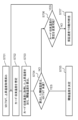
- SoC 106 has acquired the maximum value MXTMT and the rising temperature (S701). SoC 106 assumes the convergence temperature of memory card 101 (S702). SoC 106 adds the acquired rising temperature to the assumed convergence temperature and further adds a positive margin to calculate the threshold temperature (S703). SoC 106 determines whether the threshold temperature calculated in step S703 is less than the acquired maximum value MXTMT (S704). If the threshold temperature is less than the acquired MXTMT, SoC 106 sets the calculated threshold temperature as the threshold temperature to be set in memory card 101 (S705).
- SoC 106 determines whether the assumed card convergence temperature can be changed (S706). For example, the SoC 106 may make a determination based on whether the rotation speed of the fan 102 mounted on the host device 100 can be increased. If the assumed card convergence temperature can be changed, the SoC 106 re-assumes the card convergence temperature (S702). If the assumed card convergence temperature cannot be changed, the SoC 106 gives up on operating at the guaranteed speed (S707).
- the command sent by SoC106 to inquire about the rising temperature may also include the guaranteed speed at which the card will operate.
- memory card 101 returns response information including the rising temperature when the card operates continuously at the guaranteed speed included in the received command. If the threshold temperature calculated from the rising temperature and convergence temperature included in the response information is not less than the maximum value MXTMT and the card's convergence temperature cannot be changed, SoC106 may change the guaranteed speed at which the card will operate.
- the memory card 101 may return response information to the command inquiring about the temperature rise value that also indicates that it may be set to the threshold temperature TMT2. Also, the memory card 101 may be configured so that information on whether it is acceptable to set the threshold temperature TMT2 can be obtained by a separate command, and the SoC 106 may obtain that information by a separate command.
- the threshold temperature calculated using the temperature rise value obtained from the memory card 101 may be set as the threshold temperature TMT2.
- the response of the rising temperature may be triggered not by a query about the rising temperature from the SoC106, but by another query (a query about the guaranteed speed).
- the rising temperature may be sent spontaneously without any inquiry from SoC106.
- Fig. 3 is a sequence diagram for explaining the operations of the host device 100 and the memory card 101 inserted into the connector 103 of the board 105. While Fig. 2 shows that the threshold temperature is calculated on the host device 100 side, Fig. 3 shows an example in which the calculation is performed on the card side.
- the memory card 101 is inserted into the connector 103 on the board 105 of the host device 100.
- the connector 103 is connected to the SoC 106 mounted on the host device 100 via a signal line.
- Information that the memory card 101 has been inserted is sent to the SoC 106 via this signal line (S301).
- SoC 106 detects the insertion of memory card 101 (S302). SoC 106 sends a command to memory card 101. Memory card 101 analyzes the received command and returns appropriate response information. This command and response information is repeated multiple times to execute the initialization process (S303). After the initialization process, memory card 101 is ready to perform operations such as writing, reading, and erasing data.
- SoC106 estimates the convergence temperature (S304). SoC106 sends a command including the convergence temperature to memory card 101. This command asks memory card 101 what the thermal throttling threshold temperature should be set to when operating at the card's specific guaranteed speed (S305).
- the memory card 101 adds the temperature rise that would occur if the card were to operate at its specific guaranteed speed to the convergence temperature, and then calculates the thermal throttling threshold temperature by adding a positive margin (S306).
- the memory card 101 returns response information including the calculated thermal throttling threshold temperature (S307).
- the SoC 106 sends a command including the threshold temperature to the memory card 101 (S308).
- the memory card 101 sets the threshold temperature included in the command as the thermal throttling threshold temperature.
- the SoC 106 writes to and reads from the memory card 101 at the guaranteed speed (S309).
- the calculation of the thermal throttling threshold temperature (S306) will be explained using FIG. 8.
- the memory card 101 has already acquired the convergence temperature from the host device 100 (S801).
- the memory card 101 extracts the rising temperature when operating at the card's specific guaranteed speed (S802).
- the memory card 101 extracts the card's specific maximum value MXTMT (S803).
- the memory card 101 adds the rising temperature to the convergence temperature, and then adds a positive margin to calculate the threshold temperature (S804).
- the memory card 101 determines whether the threshold temperature is less than the maximum corresponding temperature value MXTMT (S805). If the threshold temperature is less than the maximum value MXTMT, the memory card 101 determines the threshold temperature calculated in step S804 as the thermal throttling threshold temperature and returns this to the host device 100 (S806). If the threshold temperature is not less than the maximum value MXTMT, the memory card 101 sends an error notification to the host device 100 indicating that the thermal throttling threshold temperature cannot be calculated (S807).
- the command sent by SoC 106 to inquire about the thermal throttling threshold temperature may include information about the guaranteed speed at which SoC 106 is to operate.
- memory card 101 returns response information including the thermal throttling threshold temperature when SoC 106 operates at the guaranteed speed included in the command.
- SoC 106 may change the guaranteed speed at which it is to operate and inquire about the thermal throttling threshold temperature again.
- the memory card 101 may return response information to the command inquiring about the thermal throttling threshold temperature that also indicates that it may be set to threshold temperature TMT2. Also, the memory card 101 may be configured so that information on whether it is acceptable to set threshold temperature TMT2 can be obtained by a separate command, and the SoC 106 may obtain that information by a separate command.
- the thermal throttling threshold temperature obtained from the memory card 101 may be set as the threshold temperature TMT2.
- the memory card 101 may include multiple thermal throttling threshold temperatures as specified information in the response information.
- the multiple threshold temperatures are included in the response information according to a predetermined rule, and the SoC 106 recognizes the threshold temperatures according to that rule.
- the recognized threshold temperature is set as the thermal throttling threshold temperature of the memory card 101.
- the memory card 101 can maintain the guaranteed speed even if the temperature inside the card exceeds the threshold temperature TMT1 and weak thermal throttling is activated, that is, if the access speed when weak thermal throttling is activated can ensure the guaranteed speed, it sets the calculated thermal throttling threshold temperature as threshold temperature TMT2 and a value lower than threshold temperature TMT2 as threshold temperature TMT1. These two thermal throttling threshold temperatures are included in the response information and returned in a predetermined order. The Soc 106 recognizes the threshold temperatures TMT1 and TMT2 according to that order and sets them as the thermal throttling threshold temperatures in the memory card 101.
- the rule may be that the lower thermal throttling setting value is the threshold temperature TMT1, and the higher thermal throttling setting value is the threshold temperature TMT2.
- the threshold temperature may be returned in response to some other inquiry (inquiry about guaranteed speed) rather than a threshold temperature inquiry from SoC106.
- the threshold temperature may be sent spontaneously without any query from SoC106.
- the SoC 106 of the host device 100 issues a command to the inserted memory card 101 requesting the temperature rise when continuously operating at the card's specific guaranteed speed.
- the memory card 101 returns response information including the temperature rise to the SoC 106.
- the SoC 106 of the host device 100 issues a command including an expected convergence temperature to the inserted memory card 101.
- the memory card 101 calculates a thermal throttling threshold temperature by adding the expected convergence temperature and the rising temperature.
- the memory card 101 returns response information including the calculated value.
- the SoC 106 sets the returned threshold temperature in the memory card 101. This makes it possible to set the thermal throttling threshold temperature appropriately. Therefore, unnecessary thermal throttling does not occur, and writing and reading become possible at the guaranteed speed.
- Embodiment 2 4 to 6, 9, and 10, a second embodiment will be described below.
- the host device 100 acquires the relationship between the threshold temperatures TMT1 and TMT2, which are card-specific thermal throttling trigger thresholds, and the guaranteed speed, and the convergence temperature and the relationship between the guaranteed speed and the temperature inside the card, calculates the threshold temperature, and further controls the cooling function of the host device 100.
- FIG. 4 is a sequence diagram for explaining the operation of the host device 100 and the memory card 101 inserted into the connector 103 of the board 105 of the host device 100.
- the memory card 101 is inserted into the connector 103 on the board 105 of the host device 100.
- the connector 103 is connected to the SoC 106 mounted on the host device 100 via a signal line.
- Information that the memory card 101 has been inserted is sent to the SoC 106 via this signal line (S401).
- SoC 106 detects the insertion of memory card 101 (S402). SoC 106 sends a command to memory card 101. Memory card 101 analyzes the received command and returns appropriate response information. This command and response information is repeated multiple times to execute the initialization process (S403). After the initialization process, memory card 101 is ready to perform operations such as writing, reading, and erasing data.
- SoC106 queries memory card 101 as to whether it holds a correspondence table showing the relationship between threshold temperatures TMT1, TMT2 and the guaranteed speed, the convergence temperature, and the relationship between the guaranteed speed and the temperature inside the card (S404). If memory card 101 holds the correspondence table, it returns response information (S405). SoC106 requests a correspondence table showing the relationship between threshold temperatures TMT1, TMT2 and the guaranteed speed, the convergence temperature, and the relationship between the guaranteed speed and the temperature inside the card (S406). Memory card 101 returns the correspondence table (S407).
- Fig. 5 is an example showing the relationship between the thermal throttling trigger thresholds TMT1 and TMT2 and the guaranteed speed, and this information is held by the memory card 101.
- the card internal temperature in correspondence table 501 is the temperature measured by temperature sensor 107 built into memory card 101.
- the meaning of correspondence table 501 is shown below.
- threshold temperature TMT2 When the temperature inside the card is equal to or higher than threshold temperature TMT2, memory card 101 performs strong thermal throttling. This indicates that the guaranteed speed is 100 MByte/sec. Similarly, when the temperature inside the card is less than threshold temperature TMT2 but greater than or equal to threshold temperature TMT1, memory card 101 performs weak thermal throttling. This indicates that the guaranteed speed is 400 MByte/sec. When the temperature inside the card is less than threshold temperature TMT1, memory card 101 does not perform thermal throttling, so this indicates that the guaranteed speed is 600 MByte/sec.
- the guaranteed speed of 100 MByte/sec can be achieved even if the temperature inside the card during continuous operation at the guaranteed speed is equal to or higher than the threshold temperature TMT2. Therefore, the threshold settings for the threshold temperatures TMT2 and TMT1 are arbitrary.
- threshold temperature TMT2 must be a threshold temperature greater than the temperature inside the card when operating continuously at the guaranteed speed.
- Threshold temperature TMT1 must be a value smaller than threshold temperature TMT2 (TMT1 ⁇ TMT2).
- threshold temperature TMT1 must be a threshold temperature higher than the temperature inside the card when operating continuously at the guaranteed speed.
- Threshold temperature TMT2 must be a value higher than threshold temperature TMT1.
- FIG. 6 shows an example of the relationship between the convergence temperature, guaranteed speed, and temperature inside the card, and this information is held by the memory card 101.
- the convergence temperature is the surface temperature of the memory card 101 that is reached as a result of control by the host device 100 during continuous operation.
- the meaning of the correspondence table 601 is shown below.
- Correspondence table 601 shows how many degrees Celsius the temperature inside the card will rise to when a certain convergence temperature is maintained and continuous operation is performed at the guaranteed speed. Specifically, when the convergence temperature is 30°C, it shows that when memory card 101 is continuously operated at a guaranteed speed of 100 MByte/sec, the temperature inside the card will be 35°C. It also shows that when the convergence temperature is 30°C, when memory card 101 is continuously operated at a guaranteed speed of 400 MByte/sec, the temperature inside the card will be 40°C, and when memory card 101 is continuously operated at a guaranteed speed of 600 MByte/sec, the temperature inside the card will be 45°C. The same is true for other convergence temperatures.
- the contents shown in the correspondence table 601 also have the following meanings:
- the contents shown in the correspondence table 601 also have the following meanings:
- SoC 106 calculates the threshold temperature for thermal throttling based on the returned correspondence tables of Figures 5 and 6 (S408). For example, assume that SoC 106 wants to access memory card 101 at 400 MByte/sec.
- FIG. 9 will be used to provide additional information on changes in the temperature inside the card.
- FIG. 9 is an example showing changes in the temperature inside the card and the threshold value during continuous operation at 400 MByte/sec. As shown in FIG. 9, the temperature inside the card rises during operation and reaches a certain temperature. The difference between the reached temperature inside the card and the convergence temperature is the temperature difference. From the correspondence table in FIG. 5, if the temperature inside the card is less than the threshold temperature TMT2 and equal to or greater than the threshold temperature TMT1, the guaranteed speed is 400 MByte/sec, and if it is less than the threshold temperature TMT1, the guaranteed speed is 600 MByte/sec.
- the threshold temperature TMT2 is set higher than the reached temperature inside the card, a guaranteed speed of 400 MByte/sec can be achieved. Assuming that the host device 100 is capable of cooling so that the convergence temperature is 40° C., it can be seen from the correspondence table 601 that the temperature inside the card will be 50° C. From this, it can be seen that the threshold temperature TMT2 needs to be set to a value greater than 50° C. SoC106 adds a positive margin, for example 5°C, to this 50°C to calculate 55°C as the threshold temperature.
- FIG. 10 is an example showing the change in temperature inside the card and the threshold value during continuous operation at 600 MByte/sec.
- the temperature inside the card rises during operation and reaches a certain temperature. If other conditions are the same, this reached temperature is higher than the temperature reached during continuous operation at 400 MByte/sec.
- the difference between this reached temperature inside the card and the convergence temperature is the temperature differential. From the correspondence table in FIG. 5, if the temperature inside the card is lower than the threshold temperature TMT1, the guaranteed speed is 600 MByte/sec.
- the threshold temperature TMT1 is set higher than the reached temperature inside the card, a guaranteed speed of 600 MByte/sec can be achieved.
- the host device 100 is capable of cooling so that the convergence temperature is 40°C
- the threshold temperature TMT1 needs to be set to a value greater than 55°C.
- the SoC 106 adds a positive margin, for example 5°C, to this 55°C to calculate a threshold temperature of 60°C.
- SoC106 sends a command to memory card 101 including selection information for whether to set the threshold temperature or thermal throttling thresholds TMT1 and TMT2 (S409).
- Memory card 101 sets the calculated threshold temperature as the thermal throttling threshold selected according to the selection information as the thermal throttling threshold temperature.
- SoC106 writes to and reads from memory card 101 at the guaranteed speed value (S410).
- the convergence temperature for realizing a certain guaranteed speed may be calculated from the obtained correspondence tables of FIG. 5 and FIG. 6. For example, assume that the host device 100 assumes access at a guaranteed speed of 600 MByte/sec, and the separately obtained MXTMT value is 95°C. In this case, it can be seen from the correspondence table 601 that if the convergence temperature is 80°C and the guaranteed speed is 600 MByte/sec, the temperature inside the card will be 100°C, exceeding the maximum value MXTMT. On the other hand, if the convergence temperature is 70°C and the guaranteed speed is 600 MByte/sec, the temperature inside the card will be 90°C, which is below the maximum value MXTMT. From this, it can be calculated that the host device 100 needs to keep the convergence temperature at 70°C or less. The host device can operate an appropriate cooling function, such as operating the fan 102, so that the card surface temperature is 70°C or less.
- the host device 100 may assume a convergence temperature based on its ability to cool the surface temperature of the memory card 101, and calculate the guaranteed speed from the temperature inside the card obtained from the acquired correspondence table 601 and the maximum value MXTMT that can be acquired separately. For example, assume that the host device 100 assumes that the convergence temperature of the memory card 101 is 80°C, and the value of the maximum value MXTMT acquired separately is 95°C. In this case, it can be seen from the correspondence table 601 that if the convergence temperature is 80°C and the guaranteed speed is 600 MByte/sec, the temperature inside the card will be 100°C. This temperature inside the card is higher than the maximum value MXTMT of 95°C.
- the internal card temperature in the correspondence table 601 may be a value indicating that it is not possible to set the internal card temperature if the internal card temperature exceeds the maximum value MXTMT, rather than a specific temperature.
- the SoC 106 may access the memory card 101 at a speed lower than the guaranteed speed.
- SoC106 may calculate multiple thresholds and send a command that includes them in a predefined order.
- one speed guarantee value corresponds to one thermal throttling operation, but multiple speed guarantee values may also be associated with each thermal throttling operation.
- the correspondence table may be returned in response to some other request (a request for guaranteed speed) rather than a request for the correspondence table from SoC106.
- the correspondence table may be sent voluntarily without a request from SoC106.
- the SoC 106 of the host device 100 issues a command to the inserted memory card 101 to confirm whether or not the memory card 101 holds a correspondence table showing the relationship between the threshold temperatures TMT1, TMT2 and the guaranteed speed, the convergence temperature, and the relationship between the guaranteed speed and the temperature inside the card.
- the memory card 101 returns response information including the presence or absence of the correspondence table to the SoC 106.
- the SoC 106 issues a command to the memory card 101 requesting a correspondence table showing the relationship between the threshold temperatures TMT1, TMT2 and the guaranteed speed, the convergence temperature, and the relationship between the guaranteed speed and the temperature inside the card.
- the memory card 101 returns response information including the correspondence table.
- the SoC 106 of the host device 100 calculates the thermal throttling threshold temperature when the host device 100 accesses the memory card 101 at the desired guaranteed speed, assuming a convergence temperature. This allows the thermal throttling setting value to be set appropriately. As a result, unnecessary thermal throttling does not occur, and writing and reading can be performed at the guaranteed speed.
- the first and second embodiments have been described as examples of the technology disclosed in this application.
- the technology in this disclosure is not limited to these, and can be applied to embodiments in which modifications, substitutions, additions, omissions, etc. are made.
- a memory card 101 is used as an example of a recording medium. Any recording medium can be used as long as data can be written to and read from it. Therefore, the recording medium is not limited to the memory card 101. However, using a memory card 101 makes it easy to handle.
- the recording medium may also be one having an M.2 or U.2 shape. Using a recording medium having an M.2 or U.2 shape makes it easy to increase the recording capacity.
- the recording medium may also be one that is built into the device. Using a built-in recording medium makes it easy to release heat to the board of the host device.
- NAND FLASH 109 is used as an example of non-volatile memory.
- the non-volatile memory may be any memory that retains data even when power is not being supplied.
- NAND FLASH is used as the non-volatile memory, it is possible to obtain non-volatile memory at low cost.
- a fan 102 is used as an example of a cooling component.
- the cooling component may be any component capable of cooling the recording medium. However, if a fan is used as the cooling component, it is inexpensive to obtain.
- a component including a Peltier element may also be used as the cooling component. Using a component including a Peltier element has the effect of making the operating noise quieter.
- a water-cooled cooling device may also be used as the cooling component. Using a water-cooled cooling device allows for highly efficient cooling.
- This disclosure is applicable to devices that write and read data while generating heat under high temperatures. Specifically, this disclosure is applicable to digital cameras, movie cameras, smartphones, drones, personal computers, etc.
Landscapes
- Engineering & Computer Science (AREA)
- Theoretical Computer Science (AREA)
- Physics & Mathematics (AREA)
- General Engineering & Computer Science (AREA)
- General Physics & Mathematics (AREA)
- Human Computer Interaction (AREA)
- Techniques For Improving Reliability Of Storages (AREA)
Priority Applications (3)
| Application Number | Priority Date | Filing Date | Title |
|---|---|---|---|
| CN202380069074.8A CN119866491A (zh) | 2022-09-28 | 2023-08-31 | 记录介质以及主机设备 |
| JP2024549922A JPWO2024070466A1 (https=) | 2022-09-28 | 2023-08-31 | |
| US19/092,046 US20250224794A1 (en) | 2022-09-28 | 2025-03-27 | Recording medium and host device |
Applications Claiming Priority (2)
| Application Number | Priority Date | Filing Date | Title |
|---|---|---|---|
| JP2022-155172 | 2022-09-28 | ||
| JP2022155172 | 2022-09-28 |
Related Child Applications (1)
| Application Number | Title | Priority Date | Filing Date |
|---|---|---|---|
| US19/092,046 Continuation US20250224794A1 (en) | 2022-09-28 | 2025-03-27 | Recording medium and host device |
Publications (1)
| Publication Number | Publication Date |
|---|---|
| WO2024070466A1 true WO2024070466A1 (ja) | 2024-04-04 |
Family
ID=90477353
Family Applications (1)
| Application Number | Title | Priority Date | Filing Date |
|---|---|---|---|
| PCT/JP2023/031731 Ceased WO2024070466A1 (ja) | 2022-09-28 | 2023-08-31 | 記録媒体およびホスト機器 |
Country Status (4)
| Country | Link |
|---|---|
| US (1) | US20250224794A1 (https=) |
| JP (1) | JPWO2024070466A1 (https=) |
| CN (1) | CN119866491A (https=) |
| WO (1) | WO2024070466A1 (https=) |
Citations (4)
| Publication number | Priority date | Publication date | Assignee | Title |
|---|---|---|---|---|
| US20190025784A1 (en) * | 2017-07-24 | 2019-01-24 | Samsung Electronics Co., Ltd. | Storage device and temperature control of electronic device including the same |
| JP2020161098A (ja) * | 2019-03-20 | 2020-10-01 | キオクシア株式会社 | 半導体記憶装置 |
| JP2021087204A (ja) * | 2019-11-29 | 2021-06-03 | キヤノン株式会社 | 記録装置、及び、記録装置の制御方法 |
| JP2021157561A (ja) * | 2020-03-27 | 2021-10-07 | キヤノン株式会社 | 記録装置、及び、記録装置の制御方法 |
-
2023
- 2023-08-31 JP JP2024549922A patent/JPWO2024070466A1/ja active Pending
- 2023-08-31 WO PCT/JP2023/031731 patent/WO2024070466A1/ja not_active Ceased
- 2023-08-31 CN CN202380069074.8A patent/CN119866491A/zh active Pending
-
2025
- 2025-03-27 US US19/092,046 patent/US20250224794A1/en active Pending
Patent Citations (4)
| Publication number | Priority date | Publication date | Assignee | Title |
|---|---|---|---|---|
| US20190025784A1 (en) * | 2017-07-24 | 2019-01-24 | Samsung Electronics Co., Ltd. | Storage device and temperature control of electronic device including the same |
| JP2020161098A (ja) * | 2019-03-20 | 2020-10-01 | キオクシア株式会社 | 半導体記憶装置 |
| JP2021087204A (ja) * | 2019-11-29 | 2021-06-03 | キヤノン株式会社 | 記録装置、及び、記録装置の制御方法 |
| JP2021157561A (ja) * | 2020-03-27 | 2021-10-07 | キヤノン株式会社 | 記録装置、及び、記録装置の制御方法 |
Also Published As
| Publication number | Publication date |
|---|---|
| JPWO2024070466A1 (https=) | 2024-04-04 |
| US20250224794A1 (en) | 2025-07-10 |
| CN119866491A (zh) | 2025-04-22 |
Similar Documents
| Publication | Publication Date | Title |
|---|---|---|
| CN101266829B (zh) | 存储卡、包含存储卡的存储系统及存储卡的操作方法 | |
| TWI578330B (zh) | Solid state semiconductor storage device with temperature control function and control method thereof | |
| US11664803B2 (en) | Apparatus for transmitting and receiving a signal, a method of operating the same, a memory device, and a method of operating the memory device | |
| EP3537304B1 (en) | Method for migrating data, host and solid static disk | |
| US11082043B2 (en) | Memory device | |
| US20200293199A1 (en) | Memory device | |
| KR102392844B1 (ko) | 메모리 컨트롤러 및 그것을 포함하는 저장 장치 | |
| US20230367518A1 (en) | Memory device | |
| US20140101386A1 (en) | Data storage device including buffer memory | |
| KR20220113238A (ko) | 데이터 캐싱 방법 및 데이터 캐싱 장치 | |
| US11243586B2 (en) | System and method for optimizing system power and performance with high power memory modules | |
| KR102583266B1 (ko) | 스토리지 모듈, 스토리지 모듈의 동작 방법, 및 스토리지 모듈을 제어하는 호스트의 동작 방법 | |
| JP2020144589A (ja) | メモリシステム | |
| US20150106573A1 (en) | Data processing system | |
| US10013180B1 (en) | Operating methods of nonvolatile memory device and data storage device including the same | |
| KR20200067633A (ko) | 메모리 장치 및 그것의 보안 데이터 처리 방법 | |
| KR102697889B1 (ko) | 데이터 저장 장치 및 그것의 동작 방법 | |
| WO2024070466A1 (ja) | 記録媒体およびホスト機器 | |
| US12236104B2 (en) | Operation method of memory module, operation method of memory controller, and operation method of memory system | |
| KR20200015260A (ko) | 데이터 저장 장치 및 그것의 동작 방법 | |
| TWI688864B (zh) | 儲存設備及儲存方法 | |
| JP7506125B2 (ja) | ストレージデバイス、及び情報処理システム | |
| JP2017130043A (ja) | メモリ装置、コンピュータシステム、メモリコントローラ、及び昇温防止方法 | |
| CN107301872B (zh) | 半导体存储器装置的操作方法 | |
| KR102655360B1 (ko) | 컨트롤러, 데이터 저장 장치 및 그것의 동작 방법 |
Legal Events
| Date | Code | Title | Description |
|---|---|---|---|
| 121 | Ep: the epo has been informed by wipo that ep was designated in this application |
Ref document number: 23871706 Country of ref document: EP Kind code of ref document: A1 |
|
| WWE | Wipo information: entry into national phase |
Ref document number: 2024549922 Country of ref document: JP |
|
| WWE | Wipo information: entry into national phase |
Ref document number: 202380069074.8 Country of ref document: CN |
|
| WWP | Wipo information: published in national office |
Ref document number: 202380069074.8 Country of ref document: CN |
|
| NENP | Non-entry into the national phase |
Ref country code: DE |
|
| 122 | Ep: pct application non-entry in european phase |
Ref document number: 23871706 Country of ref document: EP Kind code of ref document: A1 |