WO2024070273A1 - データ符号化装置、データ復号装置およびデータ処理システム - Google Patents
データ符号化装置、データ復号装置およびデータ処理システム Download PDFInfo
- Publication number
- WO2024070273A1 WO2024070273A1 PCT/JP2023/029263 JP2023029263W WO2024070273A1 WO 2024070273 A1 WO2024070273 A1 WO 2024070273A1 JP 2023029263 W JP2023029263 W JP 2023029263W WO 2024070273 A1 WO2024070273 A1 WO 2024070273A1
- Authority
- WO
- WIPO (PCT)
- Prior art keywords
- feature
- video
- decoding
- encoding
- bitstream
- Prior art date
- Legal status (The legal status is an assumption and is not a legal conclusion. Google has not performed a legal analysis and makes no representation as to the accuracy of the status listed.)
- Ceased
Links
Images


Classifications
-
- H—ELECTRICITY
- H04—ELECTRIC COMMUNICATION TECHNIQUE
- H04N—PICTORIAL COMMUNICATION, e.g. TELEVISION
- H04N19/00—Methods or arrangements for coding, decoding, compressing or decompressing digital video signals
- H04N19/65—Methods or arrangements for coding, decoding, compressing or decompressing digital video signals using error resilience
- H04N19/68—Methods or arrangements for coding, decoding, compressing or decompressing digital video signals using error resilience involving the insertion of resynchronisation markers into the bitstream
-
- H—ELECTRICITY
- H04—ELECTRIC COMMUNICATION TECHNIQUE
- H04N—PICTORIAL COMMUNICATION, e.g. TELEVISION
- H04N19/00—Methods or arrangements for coding, decoding, compressing or decompressing digital video signals
- H04N19/46—Embedding additional information in the video signal during the compression process
- H04N19/463—Embedding additional information in the video signal during the compression process by compressing encoding parameters before transmission
-
- H—ELECTRICITY
- H04—ELECTRIC COMMUNICATION TECHNIQUE
- H04N—PICTORIAL COMMUNICATION, e.g. TELEVISION
- H04N21/00—Selective content distribution, e.g. interactive television or video on demand [VOD]
- H04N21/20—Servers specifically adapted for the distribution of content, e.g. VOD servers; Operations thereof
- H04N21/23—Processing of content or additional data; Elementary server operations; Server middleware
- H04N21/234—Processing of video elementary streams, e.g. splicing of video streams or manipulating encoded video stream scene graphs
- H04N21/23418—Processing of video elementary streams, e.g. splicing of video streams or manipulating encoded video stream scene graphs involving operations for analysing video streams, e.g. detecting features or characteristics
-
- H—ELECTRICITY
- H04—ELECTRIC COMMUNICATION TECHNIQUE
- H04N—PICTORIAL COMMUNICATION, e.g. TELEVISION
- H04N21/00—Selective content distribution, e.g. interactive television or video on demand [VOD]
- H04N21/20—Servers specifically adapted for the distribution of content, e.g. VOD servers; Operations thereof
- H04N21/23—Processing of content or additional data; Elementary server operations; Server middleware
- H04N21/242—Synchronisation processes, e.g. processing of PCR [Programme Clock References]
-
- H—ELECTRICITY
- H04—ELECTRIC COMMUNICATION TECHNIQUE
- H04N—PICTORIAL COMMUNICATION, e.g. TELEVISION
- H04N21/00—Selective content distribution, e.g. interactive television or video on demand [VOD]
- H04N21/40—Client devices specifically adapted for the reception of or interaction with content, e.g. set-top-box [STB]; Operations thereof
- H04N21/43—Processing of content or additional data, e.g. demultiplexing additional data from a digital video stream; Elementary client operations, e.g. monitoring of home network or synchronising decoder's clock; Client middleware
- H04N21/44—Processing of video elementary streams, e.g. splicing a video clip retrieved from local storage with an incoming video stream or rendering scenes according to encoded video stream scene graphs
- H04N21/44008—Processing of video elementary streams, e.g. splicing a video clip retrieved from local storage with an incoming video stream or rendering scenes according to encoded video stream scene graphs involving operations for analysing video streams, e.g. detecting features or characteristics in the video stream
-
- H—ELECTRICITY
- H04—ELECTRIC COMMUNICATION TECHNIQUE
- H04N—PICTORIAL COMMUNICATION, e.g. TELEVISION
- H04N21/00—Selective content distribution, e.g. interactive television or video on demand [VOD]
- H04N21/80—Generation or processing of content or additional data by content creator independently of the distribution process; Content per se
- H04N21/83—Generation or processing of protective or descriptive data associated with content; Content structuring
-
- H—ELECTRICITY
- H04—ELECTRIC COMMUNICATION TECHNIQUE
- H04N—PICTORIAL COMMUNICATION, e.g. TELEVISION
- H04N19/00—Methods or arrangements for coding, decoding, compressing or decompressing digital video signals
- H04N19/10—Methods or arrangements for coding, decoding, compressing or decompressing digital video signals using adaptive coding
- H04N19/134—Methods or arrangements for coding, decoding, compressing or decompressing digital video signals using adaptive coding characterised by the element, parameter or criterion affecting or controlling the adaptive coding
- H04N19/157—Assigned coding mode, i.e. the coding mode being predefined or preselected to be further used for selection of another element or parameter
- H04N19/159—Prediction type, e.g. intra-frame, inter-frame or bidirectional frame prediction
-
- H—ELECTRICITY
- H04—ELECTRIC COMMUNICATION TECHNIQUE
- H04N—PICTORIAL COMMUNICATION, e.g. TELEVISION
- H04N19/00—Methods or arrangements for coding, decoding, compressing or decompressing digital video signals
- H04N19/10—Methods or arrangements for coding, decoding, compressing or decompressing digital video signals using adaptive coding
- H04N19/169—Methods or arrangements for coding, decoding, compressing or decompressing digital video signals using adaptive coding characterised by the coding unit, i.e. the structural portion or semantic portion of the video signal being the object or the subject of the adaptive coding
- H04N19/17—Methods or arrangements for coding, decoding, compressing or decompressing digital video signals using adaptive coding characterised by the coding unit, i.e. the structural portion or semantic portion of the video signal being the object or the subject of the adaptive coding the unit being an image region, e.g. an object
- H04N19/172—Methods or arrangements for coding, decoding, compressing or decompressing digital video signals using adaptive coding characterised by the coding unit, i.e. the structural portion or semantic portion of the video signal being the object or the subject of the adaptive coding the unit being an image region, e.g. an object the region being a picture, frame or field
Definitions
- the present invention relates to a data encoding device, a data decoding device, a data encoding method, a data decoding method, and a data processing system used for machine recognition task processing.
- SC29 one of the Sub-Committees (SCs) of ISO/IEC JTC1, is responsible for standardizing the coding of audio, image, and multimedia information.
- WG11 one of the Working Groups (WGs), is responsible for video coding, media transmission, streaming, audio coding, etc.
- VCM Video Coding for Machines
- FIG. 17 is a block diagram showing a data processing system that uses a VCM.
- the data processing system shown in FIG. 17 includes a VCM encoder 300 and a VCM decoder 400.
- the VCM encoder 300 and the VCM decoder 400 are connected to each other so that they can communicate with each other via a transmission path, for example. Take as an example a case in which the VCM encoder 300 generates a video bitstream and a feature bitstream related to feature A for task A of a certain machine processing.
- the VCM encoder 300 includes a video encoder 301, a feature extractor 302, and a feature encoder 303.
- the video encoder 301 encodes the video frames (see FIG. 17) at each time of the digitized video signal to generate a video bitstream.
- the feature extractor 302 extracts feature A of the video signal from the video frame at each time.
- the feature encoder 303 encodes feature A to generate a feature bit stream.
- the VCM decoder 400 has a video decoder 401 and a feature decoder 402.
- Video decoder 401 decodes the video bitstream to generate a decoded video signal.
- the decoded video signal is used for human viewing and visual confirmation.
- the decoded video signal may also be used for task X, which is a machine processing task separate from task A.
- the feature decoder 402 decodes the feature bit stream to generate feature A (decoded feature A).
- the decoded feature A is used for task A of machine processing.
- the present invention aims to ensure simultaneous random access to the video bitstream and the feature bitstream.
- the data encoding device includes a video encoding means for encoding video to generate a video bitstream, a feature encoding means for encoding features of the video to generate a feature bitstream, and a synchronization means for synchronizing random access points in the video bitstream and random access points in the feature bitstream.
- the data decoding device includes a video decoding means for receiving and decoding a video bitstream in which video is encoded and a random access point is set, and a feature decoding means for receiving and decoding a feature bitstream in which video features are encoded and a random access point is set that is aligned in time with the random access point.
- the data encoding method encodes video to generate a video bitstream, encodes features of the video to generate a feature bitstream, and synchronizes random access points in the video bitstream and random access points in the feature bitstream.
- the data decoding method receives and decodes a video bitstream in which video is encoded and generated, and in which random access points are set, and receives and decodes a feature bitstream in which video features are encoded and generated, and in which random access points that are aligned in time with the random access points are set.
- the data encoding program of the present invention causes a computer to execute a process of encoding video to generate a video bitstream, a process of encoding features of the video to generate a feature bitstream, and a process of synchronizing random access points in the video bitstream with random access points in the feature bitstream.
- the present invention ensures simultaneous random access to the video bitstream and the feature bitstream.
- FIG. 11 is an explanatory diagram showing an example of a relationship in the time direction between a video bit stream and a feature bit stream.
- 1 is a block diagram illustrating a data processing system according to a first embodiment.
- 4 is a flowchart showing the operation of a VCM encoder in the first embodiment.
- 4 is a flowchart showing the operation of the VCM decoder in the first embodiment.
- FIG. 11 is an explanatory diagram showing an example of a relationship in the time direction between a video bit stream and a feature bit stream.
- 1 is a block diagram showing a data processing system according to a second embodiment; 10 is a flowchart showing the operation of a VCM encoder in the second embodiment.
- FIG. 10 is a flowchart showing the operation of a VCM decoder according to the second embodiment.
- FIG. 11 is an explanatory diagram showing an example of a relationship in the time direction between a video bit stream and a feature bit stream.
- FIG. 11 is an explanatory diagram illustrating a first modified example of the data processing system.
- FIG. 11 is an explanatory diagram showing encoding of feature frame data using an error correction code.
- FIG. 11 is an explanatory diagram showing decoding of feature frame data using an error correction code.
- FIG. 1 is a block diagram showing a specific example configuration of a data processing system. 1 is a block diagram illustrating an example of the configuration of an information processing system.
- 1 is a block diagram showing a main part of a data encoding device;
- 1 is a block diagram showing a main part of a data encoding device;
- 1 is a block diagram showing a data processing system using a VCM;
- Figure 1 is an explanatory diagram showing an example of the relationship in the time direction between a video bitstream (video frame data) and a feature bitstream (feature frame data).
- arrows indicate frame dependencies.
- Circles indicate frames that have no dependencies on other frames.
- frames marked with circles are frames in which closed encoding and decoding processes are performed within the frame.
- a position in the time direction where such a frame exists is called a random access point.
- the width of the rectangle indicating a frame corresponds to the amount of data.
- a frame at a random access point in a video bitstream is an encoded I (Intra coded) video frame.
- the random access points in the video bitstream and the random access points in the feature bitstream are not synchronized.
- the random access points in the video bitstream and the random access points in the feature bitstream are shifted in time.
- synchronization of random access points means that the random access points appear at the same time in both bitstreams.
- Simultaneous random access means that the random access points appear at the same time in both bitstreams.
- the random access point in the video bitstream is misaligned with the random access point in the feature bitstream, then, for example, it is not possible to start a machine recognition task that uses feature A at the time when the video decoder 401 plays the frame at the random access point (e.g., time t+2 shown in Figure 1).
- the two random access points may happen to coincide. In that case, the overall amount of data (total data volume) increases when the random access point appears. In other words, the amount of data transmitted increases instantaneously.
- Predictive coding includes intra prediction and inter prediction.
- intra prediction and inter prediction will be explained.
- intra prediction and inter prediction will be explained with respect to video bitstreams.
- Intra prediction is a prediction that does not use an image of a reconstructed video frame whose display time is different from the video frame at the target time of encoding.
- an image block encoded based on intra prediction is referred to as an intra-coded image block.
- Inter prediction is a prediction that uses an image of a reconstructed video frame whose display time is different from the video frame at the target time of encoding.
- an image block encoded based on inter prediction is referred to as an inter-coded image block. Note that inter prediction is also called motion compensated prediction.
- An encoded video frame that is composed only of intra-coded image blocks is called an I video frame.
- An encoded video frame that is not composed of intra-coded image blocks is called a non-I video frame.
- Non-I video frames include P (Predictive) video frames and B (Bi-directional predicted) video frames.
- B video frames can include inter-coded image blocks that use one reconstructed video frame for inter prediction, and inter-coded image blocks that use two reconstructed video frames simultaneously for inter prediction.
- intra prediction for features In the case of feature bitstreams, prediction that does not use features of a video frame whose display time is different from the video frame whose encoding time is the target time is referred to as intra prediction for features.
- features coded based on intra prediction are referred to as intra coding features.
- inter prediction for features prediction that uses features of a video frame whose display time is different from the video frame whose encoding time is the target time.
- features coded based on inter prediction are referred to as inter coding features.
- a frame that consists only of intra-coded features is called an I feature frame.
- a frame that does not consist of intra-coded features is called a non-I feature frame.
- FIG. 2 is a block diagram showing a data processing system according to the first embodiment.
- the data processing system shown in Fig. 2 includes a VCM encoder 100 and a VCM decoder 200.
- the VCM encoder 100 and the VCM decoder 200 are communicably connected to each other via a transmission path, for example.
- a transmission path for example.
- an example is taken of the case where the VCM encoder 100 generates a video bitstream and a feature bitstream related to feature A for task A of a certain machine processing.
- the VCM encoder 100 includes a video encoder 101, a feature extractor 102, a feature encoder 103, and a controller 104.
- the video encoder 101 generates a video bitstream by encoding the video frames of the digitized video signal at each time point with a video frame type (I video frame type or non-I video frame type) supplied from the controller 104.
- a video frame type I video frame type or non-I video frame type
- the video encoder 101 performs encoding processing based on the H.266/Versatile Video Coding (VVC) standard.
- VVC Very Low Efficiency Video Coding
- the video encoder 101 may also perform encoding processing based on other standards such as the H.265/High Efficiency Video Coding (HEVC) standard or the H.264/Advanced Video Coding (AVC) standard.
- HEVC High Efficiency Video Coding
- AVC Advanced Video Coding
- the feature extractor 102 extracts feature A of the video signal from the video frame at each time.
- the feature encoder 103 encodes feature A with a feature frame type (I feature frame type or non-I feature frame type) supplied from the controller 104 to generate a feature bit stream.
- a feature frame type I feature frame type or non-I feature frame type
- the controller 104 determines the type of video frame (video frame type) and the type of feature frame (feature frame type) to be encoded by the video encoder 101 and the feature encoder 103, respectively.
- the controller 104 supplies the video frame type to the video encoder 101 as a control signal.
- the controller 104 also outputs the feature frame type to the feature encoder 103 as a control signal.
- the controller 104 synchronizes the output timing of a control signal indicating an I video frame with the output timing of a control signal indicating an I feature frame so as to guarantee simultaneous random access to the video bitstream and the feature bitstream. For example, the controller 104 synchronizes when a predetermined period has elapsed. Note that guaranteeing simultaneous random access to the video bitstream and the feature bitstream means, for example, that it is guaranteed that the random access points in the feature bitstream and the random access points in the video bitstream are aligned in time.
- synchronizing the random access points of a video frame and a feature frame means aligning the random access points of both of them in time.
- the video encoder 101 performs encoding based on the I video frame type
- the feature encoder 103 performs encoding based on the I feature frame type.
- the VCM decoder 200 includes a video decoder 201 and a feature decoder 202.
- the video decoder 201 decodes the video bitstream to generate a decoded video signal.
- the decoded video signal is used for human viewing and visual confirmation.
- the decoded video signal may also be used for task X, which is a machine processing task separate from task A (see FIG. 17).
- the feature decoder 202 decodes the feature bit stream to generate decoded feature A.
- the decoded feature A is used for machine processing task A (see FIG. 17).
- FIG. 3 is a flowchart showing the operation of the VCM encoder 100. The process shown in FIG. 3 is executed for each frame.
- the controller 104 in the VCM encoder 100 determines the video frame type and the feature frame type (step S100). As described above, for example, the controller 104 periodically determines the video frame type to be an I video frame type and the feature frame type to be an I feature frame type. When using a period to determine the frame type, the controller 104 determines the video frame type to a non-I video frame type and the feature frame type to a non-I feature frame type when a predetermined period has not elapsed.
- the controller 104 outputs a control signal indicating the video frame type to the video encoder 101, and outputs a control signal indicating the feature frame type to the feature encoder 103.
- the video encoder 101 encodes the video frames with the video frame type specified by the control signal from the controller 104 to generate a video bitstream (step S101).
- the feature extractor 102 extracts features from the video frames (step S102).
- the feature encoder 103 encodes the features using a feature frame type specified by a control signal from the controller 104 to generate a feature bit stream (step S103).
- the video encoder 101 sends the video bit stream, for example, to a transmission path (step S104).
- the feature encoder 103 sends the feature bit stream, for example, to a transmission path (step S105).
- Figure 4 is a flowchart showing the operation of the VCM decoder 200.
- the video decoder 201 in the VCM decoder 200 decodes the received video bitstream to generate a decoded video signal (step S201).
- the feature decoder 202 decodes the feature bitstream to generate decoded features (step S202).
- the video decoder 201 outputs the decoded video signal (step S203).
- the feature decoder 202 outputs the decoded features (step S204).
- FIG. 5 is an explanatory diagram showing an example of the relationship in the time direction between a video bit stream and a feature bit stream in the first embodiment.
- the arrows indicate frames at random access points.
- Frames at random access points are frames that have no dependency on other frames.
- the width of the rectangle indicating a frame corresponds to the amount of data.
- a system that uses the video bitstream and feature bitstream output by the VCM decoder 200 can immediately begin machine recognition tasks based on features at the same time as a given video frame.
- FIG. 6 is a block diagram showing a data processing system according to the second embodiment.
- the data processing system shown in Fig. 6 includes a VCM encoder 110 and a VCM decoder 210.
- the VCM encoder 110 and the VCM decoder 210 are connected to each other so as to be able to communicate with each other via a transmission path, for example.
- an example is also taken in which the VCM encoder 110 generates a video bitstream and a feature bitstream related to feature A for task A of a certain machine processing.
- the VCM encoder 110 includes a video encoder 101, a feature extractor 102, a side information generator 105, a feature encoder 106, and a controller 104.
- the functions of the video encoder 101, the feature extractor 102, and the controller 104 are the same as those in the first embodiment.
- the side information generator 105 generates information that is correlated with the feature A extracted by the feature extractor 102 from the reconstructed video signal generated inside the video encoder 101.
- the information that is correlated with the feature A extracted by the feature extractor 102 is referred to as side information A'.
- the reconstructed video signal in the video encoder 101 is a video signal (video frame) generated by a decoding function included in the video encoder 101.
- the side information generator 105 generates the side information A' by, for example, the same process as that executed by the feature extractor 102.
- the feature encoder 106 has the following functions in addition to the functions of the feature encoder 103 in the first embodiment. That is, when encoding an I feature frame type, the feature encoder 106 reduces the amount of data of the feature frame by encoding the feature frame based on the correlation between feature A and side information A'.
- side information generator 105 generates side information A' from the reconstructed video signal in video encoder 101 by the same process as that executed by feature extractor 102.
- side information generator 105 extracts features from the reconstructed video signal as side information A'.
- feature encoder 106 predictively encodes feature A with the features (side information A') extracted by side information generator 105, thereby reducing the amount of data in the feature frame. This is because feature A of the input video signal and the features of the reconstructed video signal are similar. Note that the higher the bit rate of the video bitstream, the higher the similarity between feature A of the video signal and the reconstructed video signal.
- the feature encoder 106 may also encode the feature frame by utilizing the correlation between feature A and side information A'.
- the VCM decoder 210 has a video decoder 201, a side information generator 203, and a feature decoder 204.
- the video decoder 201 is the same as that in the first embodiment. That is, the video decoder 201 decodes a video bitstream to generate a decoded video signal.
- the decoded video signal is used for human viewing and visual confirmation.
- the decoded video signal may also be used for task X, which is a machine processing task different from task A (see FIG. 17).
- side information generator 203 When a video frame of I video frame type is decoded, side information generator 203 operates in the same manner as side information generator 105 in VCM encoder 110 to generate side information A'. However, while side information generator 105 generates side information A' from the reconstructed video signal, side information generator 203 generates side information A' from the decoded video signal.
- the feature decoder 204 has the following functions in addition to the functions of the feature decoder 202 in the first embodiment. That is, when decoding a feature frame of the I feature frame type, the feature decoder 204 decodes the feature frame based on the correlation between feature A and side information A'.
- the feature decoder 204 can decode the feature frame by performing the inverse process of the predictive coding performed by the feature encoder 106. For example, the feature decoder 204 predictively decodes the features decoded from the feature bit stream using the features extracted by the side information generator 105.
- Figure 7 is a flowchart showing the operation of the VCM encoder 110. The process shown in Figure 7 is executed for each frame.
- steps S100 to S102 is the same as that in the first embodiment.
- the side information generator 105 generates side information A' from the reconstructed video signal generated inside the video encoder 101 (step S301).
- the feature encoder 106 predictively encodes the feature A using the feature (side information A') extracted by the side information generator 105 to generate a feature bit stream (step S302).
- the video encoder 101 sends the video bitstream, for example, to a transmission path (step S104).
- the feature encoder 103 sends the feature bitstream, for example, to a transmission path (step S105).
- Figure 8 is a flowchart showing the operation of the VCM decoder 210.
- the video decoder 201 decodes the received video bitstream to generate a decoded video signal (step S201).
- the side information generator 203 generates side information A' from the decoded video signal when a video frame of the I video frame type is decoded (step S401).
- the feature decoder 204 decodes the feature bit stream to generate decoded features (step S402), as in the first embodiment. However, as described above, in this embodiment, when decoding a feature frame of the I feature frame type, the feature decoder 204 decodes the feature frame by utilizing the correlation between feature A and side information A'.
- the video decoder 201 outputs the decoded video signal (step S203).
- the feature decoder 204 outputs the decoded features (step S204).
- FIG. 9 is an explanatory diagram showing an example of the relationship in the time direction between a video bitstream and a feature bitstream in the first embodiment.
- the arrows (except for the arrow relating to "reduce data volume") indicate frames at random access points. Frames at random access points are frames that have no dependency on other frames. The width of the rectangle indicating a frame corresponds to the data volume.
- the feature frame is encoded using the correlation between the feature A and the side information A', so the amount of data of the feature frame at the random access point is reduced. As a result, the increase in the total amount of data at the random access point is suppressed.
- the video encoder 101 and the feature encoders 103 and 106 may add identification headers to the beginning of the video frame data and the beginning of the feature frame data to identify random access points.
- the identification header of the video frame data contains information indicating whether it is an I video frame, a P video frame, or a B video frame.
- the identification header of the feature frame data contains information indicating whether it is an I feature frame or a non-I feature frame.
- the identification header of the feature frame data further includes information indicating whether or not it has been encoded using side information.
- the decoding side can check random accessibility without decrypting the contents of the video frame data and feature frame data. This further improves interoperability between the encoding side and the decoding side.
- the feature extracted from the video frames of the reconstructed video signal by the same process as that executed by the feature extractor 102 is defined as side information A'.
- the encoded data itself is also possible to use the encoded data itself as side information.
- the feature extracted by the same process as that executed by the feature extractor 102 will be referred to as feature A'.
- error-correcting codes can be applied as described in Non-Patent Document 2.
- Y(A,t) be the encoded data of feature A extracted by the feature extractor 102 from a video frame at time t of the input video signal.
- Y(A,t) be the encoded data of feature A' be the side information Y(A',t).
- the encoding of feature A' is shown in FIG. 11. That is, the feature encoder 106 multiplies the encoded data Y(A,t) to be sent by a check matrix to generate a syndrome, which is then converted into encoded data.
- the feature encoder 106 determines the number of columns M of the check matrix based on the correlation between the encoded data Y(A,t) (N-bit data) to be sent and the side information Y(A',t). The feature encoder 106 multiplies the encoded data Y(A,t) by a check matrix with N rows and M columns to generate a syndrome (M-bit data). The feature encoder 106 then outputs the syndrome as feature frame data. Note that if M ⁇ N, the amount of data is reduced.
- the decoding of feature A' is as shown in Figure 12. That is, the feature decoder 204 can obtain the decoded feature by using the error-corrected Y(A, t) as the decoded value based on the relationship between the side information Y(A', t), the check matrix, and the syndrome (M-bit data).
- the feature encoder 106 only needs to include the ID of the check matrix used for the number of columns M in the identification header.
- the syndrome may be calculated collectively for data obtained by concatenating all of the feature frame data, rather than calculating the syndrome independently for each feature frame data.
- the overhead caused by applying a check matrix with a small number of columns can be suppressed.
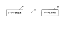
- Fig. 13 is a block diagram showing a specific example of the configuration of a data processing system.
- the data processing system shown in Fig. 13 is a system in which a data encoding device 10 (corresponding to VCM encoder 100 in the first embodiment or VCM encoder 110 in the second embodiment) and a data decoding device 20 (corresponding to VCM decoder 200 in the first embodiment or VCM decoder 210 in the second embodiment) are connected by a transmission path (wireless transmission path or wired transmission path) 30.
- a transmission path wireless transmission path or wired transmission path
- the data encoding device 10 can generate a video bitstream and a feature bitstream having the characteristics described in each of the above embodiments. Also, in the data processing system, the data decoding device 20 can decode a video bitstream and a feature bitstream having the characteristics described in each of the above embodiments.
- each of the above embodiments can be configured using hardware, but can also be realized using a computer program.
- the information processing system shown in FIG. 14 comprises a processor 1001 such as a CPU (Central Processing Unit), a program memory 1002, a storage medium 1003 for storing video data, and a storage medium 1004 for storing a bit stream.
- Storage medium 1003 and storage medium 1004 may be separate storage media or may be storage areas made up of the same storage medium.
- a magnetic storage medium such as a hard disk can be used as the storage medium.
- the program memory 1002 stores a program (a data encoding program or a data decoding program) for implementing the functions of each block shown in each of the above embodiments.
- the processor 1001 then executes processing according to the programs stored in the program memory 1002, thereby realizing the functions of the data encoding device 10, the VCM encoders 100 and 110, the data decoding device 20, and the VCM decoders 200 and 210 shown in each embodiment.
- the processor 1001 executes processing according to a data encoding program (specifically, a VCM encoding program) for implementing the functions of each block in the VCM encoder 100 shown in FIG. 2, thereby implementing the functions of the VCM encoder 100.
- the processor 1001 executes processing according to a data decoding program (specifically, a VCM decoding program) for implementing the functions of each block in the VCM decoder 200 shown in FIG. 2, thereby implementing the functions of the VCM decoder 200.
- the program memory 1002 is a non-transitory computer readable medium.
- the program may be stored on various types of transitory computer readable medium.
- the program may be supplied to the transitory computer readable medium, for example, via a wired or wireless communication path, i.e., via an electrical signal, an optical signal, or an electromagnetic wave.
- FIG. 15 is a block diagram showing the main parts of a data encoding device.
- the data encoding device 10 shown in FIG. 15 includes a video encoding unit (video encoding means) 11 (realized by a video encoder 101 in the embodiment) that encodes video to generate a video bitstream, a feature encoding unit (feature encoding means) 12 (realized by feature encoders 103 and 106 in the embodiment) that encodes features of the video to generate a feature bitstream, and a synchronization unit (synchronization means) 13 (realized by a controller 104 in the embodiment) that synchronizes random access points in the video bitstream and random access points in the feature bitstream.
- video encoding unit video encoding means
- feature encoding means realized by feature encoders 103 and 106 in the embodiment
- synchronization unit synchronization means 13 (realized by a controller 104 in the embodiment) that synchronizes random access points in the video bitstream and random access points in the feature bitstream.
- the data encoding device 10 includes a first feature extraction unit (first feature extraction means: in an embodiment, realized by a side information generator 105) that extracts features of the input video, and a second feature extraction unit (second feature extraction means: in an embodiment, realized by a feature encoder 106) that extracts features of the video generated by a decoding process included in the encoding process by the video encoding unit 11, and the feature encoding unit 12 may be configured to encode the features based on the correlation between the features extracted from the input video and the features extracted from the video generated by the decoding process.
- first feature extraction means in an embodiment, realized by a side information generator 105
- second feature extraction unit second feature extraction means: in an embodiment, realized by a feature encoder 106
- the feature encoding unit 12 may be configured to encode the features based on the correlation between the features extracted from the input video and the features extracted from the video generated by the decoding process.
- FIG. 16 is a block diagram showing the main parts of a data decoding device.
- the data decoding device 20 shown in FIG. 16 includes a video decoding unit (video decoding means) 21 that receives and decodes a video bitstream generated by encoding video and having random access points set therein, and a feature decoding unit (feature decoding means) 22 that receives and decodes a feature bitstream generated by encoding video features and having random access points set therein that are aligned in time with the random access points.
- video decoding unit video decoding means
- feature decoding means 22 receives and decodes a feature bitstream generated by encoding video features and having random access points set therein that are aligned in time with the random access points.
- the data decoding device 20 includes a feature extraction unit (feature extraction means: in the embodiment, this is realized by the side information generator 203) that extracts features of the decoded video obtained by decoding the video bitstream, and the feature decoding unit 22 may be configured to perform decoding based on the correlation between the features obtained by decoding the feature bitstream and the features extracted from the decoded video.
- feature extraction means in the embodiment, this is realized by the side information generator 203
- the feature decoding unit 22 may be configured to perform decoding based on the correlation between the features obtained by decoding the feature bitstream and the features extracted from the decoded video.
- the data encoding device according to claim 1, wherein the feature encoding means encodes the feature based on a correlation between the feature extracted from the input video and the feature extracted from the video generated by the decoding process.
- a video decoding unit that receives and decodes a video bitstream in which a video is encoded and a random access point is set; and a feature decoding means for receiving and decoding a feature bit stream in which features of the video are encoded and generated, and in which a random access point that is temporally aligned with the random access point is set.
- a feature extraction unit is provided for extracting a feature of a decoded video obtained by decoding the video bitstream,
- the data decoding device according to claim 4, wherein the feature decoding means performs decoding based on a correlation between a feature obtained by decoding the feature bit stream and a feature extracted from the decoded video.
- a video is encoded and generated, and a video bitstream in which a random access point is set is received and decoded; a data decoding method for receiving and decoding a feature bit stream in which the feature of the video is generated by encoding and a random access point that is time-aligned with the random access point is set.
- a computer includes: encoding the video to generate a video bitstream; A process of encoding the features of the video to generate a feature bitstream; and a process of synchronizing a random access point in the video bit stream with a random access point in the feature bit stream.
- a computer includes: receiving and decoding a video bitstream in which a video is encoded and a random access point is set; receiving and decoding a feature bit stream in which the features of the video are encoded and generated, and in which a random access point that is temporally aligned with the random access point is set.
Landscapes
- Engineering & Computer Science (AREA)
- Multimedia (AREA)
- Signal Processing (AREA)
- Compression Or Coding Systems Of Tv Signals (AREA)
Priority Applications (3)
| Application Number | Priority Date | Filing Date | Title |
|---|---|---|---|
| EP23871515.5A EP4598026A4 (en) | 2022-09-28 | 2023-08-10 | DATA ENCODING DEVICE, DATA DECODING DEVICE AND DATA PROCESSING SYSTEM |
| JP2024549840A JP7831618B2 (ja) | 2022-09-28 | 2023-08-10 | データ符号化装置、データ復号装置およびデータ処理システム |
| CN202380067891.XA CN119908115A (zh) | 2022-09-28 | 2023-08-10 | 数据编码设备、数据解码设备和数据处理系统 |
Applications Claiming Priority (2)
| Application Number | Priority Date | Filing Date | Title |
|---|---|---|---|
| JP2022154436 | 2022-09-28 | ||
| JP2022-154436 | 2022-09-28 |
Publications (1)
| Publication Number | Publication Date |
|---|---|
| WO2024070273A1 true WO2024070273A1 (ja) | 2024-04-04 |
Family
ID=90477070
Family Applications (1)
| Application Number | Title | Priority Date | Filing Date |
|---|---|---|---|
| PCT/JP2023/029263 Ceased WO2024070273A1 (ja) | 2022-09-28 | 2023-08-10 | データ符号化装置、データ復号装置およびデータ処理システム |
Country Status (4)
| Country | Link |
|---|---|
| EP (1) | EP4598026A4 (https=) |
| JP (1) | JP7831618B2 (https=) |
| CN (1) | CN119908115A (https=) |
| WO (1) | WO2024070273A1 (https=) |
Citations (1)
| Publication number | Priority date | Publication date | Assignee | Title |
|---|---|---|---|---|
| WO2022139617A1 (en) * | 2020-12-24 | 2022-06-30 | Huawei Technologies Co., Ltd. | Encoding with signaling of feature map data |
Family Cites Families (5)
| Publication number | Priority date | Publication date | Assignee | Title |
|---|---|---|---|---|
| JP3724203B2 (ja) * | 1998-03-10 | 2005-12-07 | ソニー株式会社 | 符号化装置および方法、並びに記録媒体 |
| US20120044322A1 (en) * | 2009-05-01 | 2012-02-23 | Dong Tian | 3d video coding formats |
| US8655156B2 (en) * | 2010-03-02 | 2014-02-18 | Cisco Technology, Inc. | Auxiliary audio transmission for preserving synchronized playout with paced-down video |
| WO2016089093A1 (ko) * | 2014-12-04 | 2016-06-09 | 엘지전자 주식회사 | 방송 신호 송수신 방법 및 장치 |
| US12334118B2 (en) * | 2018-11-19 | 2025-06-17 | Netflix, Inc. | Techniques for identifying synchronization errors in media titles |
-
2023
- 2023-08-10 CN CN202380067891.XA patent/CN119908115A/zh active Pending
- 2023-08-10 JP JP2024549840A patent/JP7831618B2/ja active Active
- 2023-08-10 WO PCT/JP2023/029263 patent/WO2024070273A1/ja not_active Ceased
- 2023-08-10 EP EP23871515.5A patent/EP4598026A4/en not_active Withdrawn
Patent Citations (1)
| Publication number | Priority date | Publication date | Assignee | Title |
|---|---|---|---|---|
| WO2022139617A1 (en) * | 2020-12-24 | 2022-06-30 | Huawei Technologies Co., Ltd. | Encoding with signaling of feature map data |
Non-Patent Citations (6)
| Title |
|---|
| "Use cases and requirements for Video Coding for Machines", ISO/IEC JTC1/SC29/WG11 W19365, April 2020 (2020-04-01) |
| KEIICHI CHONO ET AL.: "Reduced-reference image quality assessment using distributed source coding", IEEE INTERNATIONAL CONFERENCE ON MULTIMEDIA AND EXPO, June 2008 (2008-06-01) |
| MA SIWEI; ZHANG XIANG; WANG SHIQI; ZHANG XINFENG; JIA CHUANMIN; WANG SHANSHE: "Joint Feature and Texture Coding: Toward Smart Video Representation via Front-End Intelligence", IEEE TRANSACTIONS ON CIRCUITS AND SYSTEMS FOR VIDEO TECHNOLOGY, IEEE, USA, vol. 29, no. 10, 1 October 2019 (2019-10-01), USA, pages 3095 - 3105, XP011748694, ISSN: 1051-8215, DOI: 10.1109/TCSVT.2018.2873102 * |
| See also references of EP4598026A4 |
| WEN GAO: "Recent Standard Development Activities on Video Coding for Machines", ARXIV:2105.12653, 26 May 2021 (2021-05-26), pages 1 - 13, XP093154173, Retrieved from the Internet <URL:https://arxiv.org/ftp/arxiv/papers/2105/2105.12653.pdf> * |
| ZHIMENG HUANG: "HMFVC: A Human-Machine Friendly Video Compression Scheme", IEEE TRANSACTIONS ON CIRCUITS AND SYSTEMS FOR VIDEO TECHNOLOGY, IEEE, USA, 1 January 2024 (2024-01-01), USA, pages 1, XP093154171, ISSN: 1051-8215, DOI: 10.1109/TCSVT.2022.3207596 * |
Also Published As
| Publication number | Publication date |
|---|---|
| JP7831618B2 (ja) | 2026-03-17 |
| CN119908115A (zh) | 2025-04-29 |
| JPWO2024070273A1 (https=) | 2024-04-04 |
| EP4598026A1 (en) | 2025-08-06 |
| EP4598026A4 (en) | 2026-01-21 |
Similar Documents
| Publication | Publication Date | Title |
|---|---|---|
| US9042456B2 (en) | Moving picture encoding/decoding apparatus and method for processing of moving picture divided in units of slices | |
| KR100603175B1 (ko) | 동화상 부호화 방법, 동화상 복호 방법, 동화상 부호화 장치, 동화상 복호 장치, 동화상 부호화 프로그램을 기록한 컴퓨터 판독 가능한 기록매체, 및 동화상 복호 프로그램을 기록한 컴퓨터 판독 가능한 기록 매체 | |
| AU2003203271B2 (en) | Image coding method and apparatus and image decoding method and apparatus | |
| US8487791B2 (en) | Parallel entropy coding and decoding methods and devices | |
| US9338453B2 (en) | Method and device for encoding/decoding video signals using base layer | |
| JP2000175187A (ja) | ビデオ圧縮のための領域ベ―スのリフレッシュ方法 | |
| JP2010515400A (ja) | 全域差ベクトルを利用した多視点映像の符号化、復号化方法及び装置 | |
| JP2017525175A (ja) | ビデオにおけるピクチャのロバストな符号化および復号化 | |
| US9326011B2 (en) | Method and apparatus for generating bitstream based on syntax element | |
| CN114257818B (zh) | 视频的编、解码方法、装置、设备和存储介质 | |
| US20110206133A1 (en) | Parallel parsing in a video decoder | |
| RU2693641C1 (ru) | Устройство, способ и программа кодирования и декодирования динамических изображений с предсказанием | |
| JP7532362B2 (ja) | 画像処理装置および方法 | |
| JP2007507128A (ja) | 参照ピクチャのリフレッシュを遅延させて行うビデオ画像の符号化および復号化 | |
| US20130170559A1 (en) | Systems and methods for region of interest video processing | |
| US20190268619A1 (en) | Motion vector selection and prediction in video coding systems and methods | |
| JP2014011572A5 (ja) | 動画像予測復号装置、方法及びプログラム | |
| WO2024070273A1 (ja) | データ符号化装置、データ復号装置およびデータ処理システム | |
| CN101682755B (zh) | 通过对图像进行分区来对图像编码/解码的方法和设备 | |
| EP4189964A1 (en) | Supporting view direction based random access of bitstream | |
| JP6197708B2 (ja) | 動画像伝送システム、動画像符号化装置、動画像復号装置及び動画像符号化用コンピュータプログラムならびに動画像復号用コンピュータプログラム | |
| US20040013200A1 (en) | Advanced method of coding and decoding motion vector and apparatus therefor | |
| KR100269882B1 (ko) | 영화부호화 및 복호화방법 및 그 장치(image coding and decoding method and related apparatus) | |
| HK1155874A (en) | A method and a system for video encoding | |
| JP2012138780A (ja) | データ配信システム、データ配信装置、データ符号化装置、及びデータ符号化方法 |
Legal Events
| Date | Code | Title | Description |
|---|---|---|---|
| 121 | Ep: the epo has been informed by wipo that ep was designated in this application |
Ref document number: 23871515 Country of ref document: EP Kind code of ref document: A1 |
|
| WWE | Wipo information: entry into national phase |
Ref document number: 2024549840 Country of ref document: JP |
|
| WWE | Wipo information: entry into national phase |
Ref document number: 202380067891.X Country of ref document: CN |
|
| WWE | Wipo information: entry into national phase |
Ref document number: 202547037273 Country of ref document: IN |
|
| WWE | Wipo information: entry into national phase |
Ref document number: 2023871515 Country of ref document: EP |
|
| NENP | Non-entry into the national phase |
Ref country code: DE |
|
| WWP | Wipo information: published in national office |
Ref document number: 202380067891.X Country of ref document: CN |
|
| ENP | Entry into the national phase |
Ref document number: 2023871515 Country of ref document: EP Effective date: 20250428 |
|
| WWP | Wipo information: published in national office |
Ref document number: 202547037273 Country of ref document: IN |
|
| WWP | Wipo information: published in national office |
Ref document number: 2023871515 Country of ref document: EP |
|
| WWW | Wipo information: withdrawn in national office |
Ref document number: 2023871515 Country of ref document: EP |