WO2024069967A1 - 液体水素タンク及びその運転方法 - Google Patents
液体水素タンク及びその運転方法 Download PDFInfo
- Publication number
- WO2024069967A1 WO2024069967A1 PCT/JP2022/036794 JP2022036794W WO2024069967A1 WO 2024069967 A1 WO2024069967 A1 WO 2024069967A1 JP 2022036794 W JP2022036794 W JP 2022036794W WO 2024069967 A1 WO2024069967 A1 WO 2024069967A1
- Authority
- WO
- WIPO (PCT)
- Prior art keywords
- tank
- pressure
- inter
- region
- liquid hydrogen
- Prior art date
- Legal status (The legal status is an assumption and is not a legal conclusion. Google has not performed a legal analysis and makes no representation as to the accuracy of the status listed.)
- Ceased
Links
Images

Classifications
-
- F—MECHANICAL ENGINEERING; LIGHTING; HEATING; WEAPONS; BLASTING
- F17—STORING OR DISTRIBUTING GASES OR LIQUIDS
- F17C—VESSELS FOR CONTAINING OR STORING COMPRESSED, LIQUEFIED OR SOLIDIFIED GASES; FIXED-CAPACITY GAS-HOLDERS; FILLING VESSELS WITH, OR DISCHARGING FROM VESSELS, COMPRESSED, LIQUEFIED, OR SOLIDIFIED GASES
- F17C3/00—Vessels not under pressure
- F17C3/02—Vessels not under pressure with provision for thermal insulation
- F17C3/04—Vessels not under pressure with provision for thermal insulation by insulating layers
-
- B—PERFORMING OPERATIONS; TRANSPORTING
- B63—SHIPS OR OTHER WATERBORNE VESSELS; RELATED EQUIPMENT
- B63B—SHIPS OR OTHER WATERBORNE VESSELS; EQUIPMENT FOR SHIPPING
- B63B25/00—Load-accommodating arrangements, e.g. stowing, trimming; Vessels characterised thereby
- B63B25/02—Load-accommodating arrangements, e.g. stowing, trimming; Vessels characterised thereby for bulk goods
- B63B25/08—Load-accommodating arrangements, e.g. stowing, trimming; Vessels characterised thereby for bulk goods fluid
- B63B25/12—Load-accommodating arrangements, e.g. stowing, trimming; Vessels characterised thereby for bulk goods fluid closed
- B63B25/16—Load-accommodating arrangements, e.g. stowing, trimming; Vessels characterised thereby for bulk goods fluid closed heat-insulated
-
- B—PERFORMING OPERATIONS; TRANSPORTING
- B65—CONVEYING; PACKING; STORING; HANDLING THIN OR FILAMENTARY MATERIAL
- B65D—CONTAINERS FOR STORAGE OR TRANSPORT OF ARTICLES OR MATERIALS, e.g. BAGS, BARRELS, BOTTLES, BOXES, CANS, CARTONS, CRATES, DRUMS, JARS, TANKS, HOPPERS, FORWARDING CONTAINERS; ACCESSORIES, CLOSURES, OR FITTINGS THEREFOR; PACKAGING ELEMENTS; PACKAGES
- B65D90/00—Component parts, details or accessories for large containers
- B65D90/02—Wall construction
-
- F—MECHANICAL ENGINEERING; LIGHTING; HEATING; WEAPONS; BLASTING
- F17—STORING OR DISTRIBUTING GASES OR LIQUIDS
- F17C—VESSELS FOR CONTAINING OR STORING COMPRESSED, LIQUEFIED OR SOLIDIFIED GASES; FIXED-CAPACITY GAS-HOLDERS; FILLING VESSELS WITH, OR DISCHARGING FROM VESSELS, COMPRESSED, LIQUEFIED, OR SOLIDIFIED GASES
- F17C13/00—Details of vessels or of the filling or discharging of vessels
- F17C13/001—Thermal insulation specially adapted for cryogenic vessels
-
- F—MECHANICAL ENGINEERING; LIGHTING; HEATING; WEAPONS; BLASTING
- F17—STORING OR DISTRIBUTING GASES OR LIQUIDS
- F17C—VESSELS FOR CONTAINING OR STORING COMPRESSED, LIQUEFIED OR SOLIDIFIED GASES; FIXED-CAPACITY GAS-HOLDERS; FILLING VESSELS WITH, OR DISCHARGING FROM VESSELS, COMPRESSED, LIQUEFIED, OR SOLIDIFIED GASES
- F17C2201/00—Vessel construction, in particular geometry, arrangement or size
- F17C2201/01—Shape
- F17C2201/0104—Shape cylindrical
-
- F—MECHANICAL ENGINEERING; LIGHTING; HEATING; WEAPONS; BLASTING
- F17—STORING OR DISTRIBUTING GASES OR LIQUIDS
- F17C—VESSELS FOR CONTAINING OR STORING COMPRESSED, LIQUEFIED OR SOLIDIFIED GASES; FIXED-CAPACITY GAS-HOLDERS; FILLING VESSELS WITH, OR DISCHARGING FROM VESSELS, COMPRESSED, LIQUEFIED, OR SOLIDIFIED GASES
- F17C2201/00—Vessel construction, in particular geometry, arrangement or size
- F17C2201/05—Size
- F17C2201/052—Size large (>1000 m3)
-
- F—MECHANICAL ENGINEERING; LIGHTING; HEATING; WEAPONS; BLASTING
- F17—STORING OR DISTRIBUTING GASES OR LIQUIDS
- F17C—VESSELS FOR CONTAINING OR STORING COMPRESSED, LIQUEFIED OR SOLIDIFIED GASES; FIXED-CAPACITY GAS-HOLDERS; FILLING VESSELS WITH, OR DISCHARGING FROM VESSELS, COMPRESSED, LIQUEFIED, OR SOLIDIFIED GASES
- F17C2201/00—Vessel construction, in particular geometry, arrangement or size
- F17C2201/05—Size
- F17C2201/054—Size medium (>1 m3)
-
- F—MECHANICAL ENGINEERING; LIGHTING; HEATING; WEAPONS; BLASTING
- F17—STORING OR DISTRIBUTING GASES OR LIQUIDS
- F17C—VESSELS FOR CONTAINING OR STORING COMPRESSED, LIQUEFIED OR SOLIDIFIED GASES; FIXED-CAPACITY GAS-HOLDERS; FILLING VESSELS WITH, OR DISCHARGING FROM VESSELS, COMPRESSED, LIQUEFIED, OR SOLIDIFIED GASES
- F17C2203/00—Vessel construction, in particular walls or details thereof
- F17C2203/03—Thermal insulations
- F17C2203/0375—Thermal insulations by gas
-
- F—MECHANICAL ENGINEERING; LIGHTING; HEATING; WEAPONS; BLASTING
- F17—STORING OR DISTRIBUTING GASES OR LIQUIDS
- F17C—VESSELS FOR CONTAINING OR STORING COMPRESSED, LIQUEFIED OR SOLIDIFIED GASES; FIXED-CAPACITY GAS-HOLDERS; FILLING VESSELS WITH, OR DISCHARGING FROM VESSELS, COMPRESSED, LIQUEFIED, OR SOLIDIFIED GASES
- F17C2203/00—Vessel construction, in particular walls or details thereof
- F17C2203/06—Materials for walls or layers thereof; Properties or structures of walls or their materials
- F17C2203/0602—Wall structures; Special features thereof
- F17C2203/0612—Wall structures
- F17C2203/0626—Multiple walls
- F17C2203/0629—Two walls
-
- F—MECHANICAL ENGINEERING; LIGHTING; HEATING; WEAPONS; BLASTING
- F17—STORING OR DISTRIBUTING GASES OR LIQUIDS
- F17C—VESSELS FOR CONTAINING OR STORING COMPRESSED, LIQUEFIED OR SOLIDIFIED GASES; FIXED-CAPACITY GAS-HOLDERS; FILLING VESSELS WITH, OR DISCHARGING FROM VESSELS, COMPRESSED, LIQUEFIED, OR SOLIDIFIED GASES
- F17C2205/00—Vessel construction, in particular mounting arrangements, attachments or identifications means
- F17C2205/03—Fluid connections, filters, valves, closure means or other attachments
- F17C2205/0302—Fittings, valves, filters, or components in connection with the gas storage device
- F17C2205/0323—Valves
- F17C2205/0332—Safety valves or pressure relief valves
-
- F—MECHANICAL ENGINEERING; LIGHTING; HEATING; WEAPONS; BLASTING
- F17—STORING OR DISTRIBUTING GASES OR LIQUIDS
- F17C—VESSELS FOR CONTAINING OR STORING COMPRESSED, LIQUEFIED OR SOLIDIFIED GASES; FIXED-CAPACITY GAS-HOLDERS; FILLING VESSELS WITH, OR DISCHARGING FROM VESSELS, COMPRESSED, LIQUEFIED, OR SOLIDIFIED GASES
- F17C2221/00—Handled fluid, in particular type of fluid
- F17C2221/01—Pure fluids
- F17C2221/012—Hydrogen
-
- F—MECHANICAL ENGINEERING; LIGHTING; HEATING; WEAPONS; BLASTING
- F17—STORING OR DISTRIBUTING GASES OR LIQUIDS
- F17C—VESSELS FOR CONTAINING OR STORING COMPRESSED, LIQUEFIED OR SOLIDIFIED GASES; FIXED-CAPACITY GAS-HOLDERS; FILLING VESSELS WITH, OR DISCHARGING FROM VESSELS, COMPRESSED, LIQUEFIED, OR SOLIDIFIED GASES
- F17C2223/00—Handled fluid before transfer, i.e. state of fluid when stored in the vessel or before transfer from the vessel
- F17C2223/01—Handled fluid before transfer, i.e. state of fluid when stored in the vessel or before transfer from the vessel characterised by the phase
- F17C2223/0146—Two-phase
- F17C2223/0153—Liquefied gas, e.g. LPG, GPL
- F17C2223/0161—Liquefied gas, e.g. LPG, GPL cryogenic, e.g. LNG, GNL, PLNG
-
- F—MECHANICAL ENGINEERING; LIGHTING; HEATING; WEAPONS; BLASTING
- F17—STORING OR DISTRIBUTING GASES OR LIQUIDS
- F17C—VESSELS FOR CONTAINING OR STORING COMPRESSED, LIQUEFIED OR SOLIDIFIED GASES; FIXED-CAPACITY GAS-HOLDERS; FILLING VESSELS WITH, OR DISCHARGING FROM VESSELS, COMPRESSED, LIQUEFIED, OR SOLIDIFIED GASES
- F17C2270/00—Applications
- F17C2270/01—Applications for fluid transport or storage
- F17C2270/0102—Applications for fluid transport or storage on or in the water
-
- F—MECHANICAL ENGINEERING; LIGHTING; HEATING; WEAPONS; BLASTING
- F17—STORING OR DISTRIBUTING GASES OR LIQUIDS
- F17C—VESSELS FOR CONTAINING OR STORING COMPRESSED, LIQUEFIED OR SOLIDIFIED GASES; FIXED-CAPACITY GAS-HOLDERS; FILLING VESSELS WITH, OR DISCHARGING FROM VESSELS, COMPRESSED, LIQUEFIED, OR SOLIDIFIED GASES
- F17C2270/00—Applications
- F17C2270/01—Applications for fluid transport or storage
- F17C2270/0134—Applications for fluid transport or storage placed above the ground
-
- Y—GENERAL TAGGING OF NEW TECHNOLOGICAL DEVELOPMENTS; GENERAL TAGGING OF CROSS-SECTIONAL TECHNOLOGIES SPANNING OVER SEVERAL SECTIONS OF THE IPC; TECHNICAL SUBJECTS COVERED BY FORMER USPC CROSS-REFERENCE ART COLLECTIONS [XRACs] AND DIGESTS
- Y02—TECHNOLOGIES OR APPLICATIONS FOR MITIGATION OR ADAPTATION AGAINST CLIMATE CHANGE
- Y02E—REDUCTION OF GREENHOUSE GAS [GHG] EMISSIONS, RELATED TO ENERGY GENERATION, TRANSMISSION OR DISTRIBUTION
- Y02E60/00—Enabling technologies; Technologies with a potential or indirect contribution to GHG emissions mitigation
- Y02E60/30—Hydrogen technology
- Y02E60/32—Hydrogen storage
Definitions
- This disclosure relates to a liquid hydrogen tank that contains liquid hydrogen.
- double-shell tanks have been known as liquefied gas tanks for storing low-temperature liquefied gas, and are equipped with an inner tank and an outer tank surrounding the inner tank, with the inter-tank area between the inner and outer tanks filled with gas.
- Patent Document 1 discloses a double-shell tank having an inner and outer tank, in which the space between the inner and outer tanks is filled with boil-off gas discharged from the inner tank. In addition, the space between the tanks is packed with insulating material.
- the gas filled between the tanks may condense and liquefy due to pressure fluctuations in the area between the tanks. If the gas between the tanks liquefies, the tank components may fall below their allowable lower limit temperature and be damaged, the insulation material placed between the tanks may deteriorate, or the heat input may increase due to the heat pipe effect.
- This disclosure has been made in consideration of the above circumstances, and its purpose is to suppress liquefaction of the gas in the inter-tank region in a liquid hydrogen tank having an inner tank containing liquid hydrogen, an outer tank surrounding the inner tank, and the inter-tank region between the inner tank and the outer tank filled with vaporized liquid hydrogen gas.
- a liquid hydrogen tank comprises: an inner tank for accommodating liquid hydrogen; An outer tank surrounding the inner tank; a thermal barrier layer disposed in an inter-tank region between the inner tank and the outer tank and covering an outer wall of the inner tank, During storage, when the inter-cell region is filled with hydrogen gas and the inner tank contains liquid hydrogen, the inter-cell pressure, which is the pressure in the inter-cell region, is lower than the saturated vapor pressure of hydrogen at a specified temperature.
- a method for operating a liquid hydrogen tank is a method for operating a liquid hydrogen tank comprising an inner tank for accommodating liquid hydrogen, an outer tank surrounding the inner tank, and a thermal barrier layer disposed in an inter-tank region between the inner tank and the outer tank and covering an outer wall of the inner tank, the method comprising the steps of: During storage, when the inter-cell region is filled with hydrogen gas and the inner tank contains liquid hydrogen, the inter-cell pressure, which is the pressure in the inter-cell region, is maintained lower than the saturated vapor pressure of hydrogen at a specified temperature.
- a liquid hydrogen tank having an inner tank containing liquid hydrogen, an outer tank surrounding the inner tank, and the space between the inner and outer tanks filled with vaporized liquid hydrogen gas, liquefaction of the gas in the space between the tanks can be suppressed.
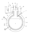
- FIG. 1 is a vertical cross-sectional view showing a schematic configuration of a liquid hydrogen tank according to one embodiment of the present disclosure.
- FIG. 2 is a vertical sectional view showing a schematic configuration of a liquid hydrogen tank according to a modified example.
- Fig. 1 is a vertical cross-sectional view showing the schematic configuration of a liquid hydrogen tank 1 according to one embodiment of the present disclosure.
- the liquid hydrogen tank 1 shown in Fig. 1 is a container that contains cryogenic liquid hydrogen.
- the liquid hydrogen tank 1 may be a cargo tank that stores liquid hydrogen as cargo, or a fuel tank that stores liquid hydrogen as fuel.
- the liquid hydrogen tank 1 may be mounted on a ship or a floating structure, or may be installed on land.
- the liquid hydrogen tank 1 comprises an inner tank 21 that contains liquid hydrogen L, and an outer tank 22 that surrounds the inner tank 21.
- the liquid hydrogen tank 1 is not limited to being a double-shelled tank, and may be a triple or more multi-shelled tank that comprises at least one tank that surrounds the outer tank 22.
- the ship's hull may function as the outer tank 22.
- the inner tank 21 and the outer tank 22 are spaced apart in the radial direction of the liquid hydrogen tank 1, and an intertank region 23 is provided between the inner tank 21 and the outer tank 22.
- a thermal barrier layer 24 is disposed in the intertank region 23.
- the thermal barrier layer 24 covers the outer wall of the inner tank 21 in the intertank region 23.
- the thermal barrier layer 24 is made of a heat insulating material, and examples of the heat insulating material include a heat insulating panel, a heat insulating sheet, and a fibrous heat insulating material.
- annular region 25 the region between the outer wall of the inner tank 21 and the thermal barrier layer 24 in the intertank region 23 is referred to as the "annular region 25", and the region between the thermal barrier layer 24 and the inner wall of the outer tank 22 is referred to as the thermal barrier outer peripheral region 26.
- the annular region 25 may be formed by a gap provided between the outer wall of the inner tank 21 and the thermal barrier layer 24, or the annular region 25 may be formed by gaps or holes formed on the surface of the thermal barrier layer 24 facing the outer wall of the inner tank 21.
- the inter-tank region 23 is filled with the same type of gas as the vaporized gas of the liquid hydrogen L contained in the inner tank 21, i.e., hydrogen gas G.
- the hydrogen gas G may be a vaporized gas produced by vaporizing the liquid hydrogen L inside the inner tank 21, or it may be a gas supplied from outside the liquid hydrogen tank 1.
- the pressure in the inter-tank region 23 is adjusted so that the hydrogen gas G in the inter-tank region 23 does not liquefy due to condensation.
- the interior of the inner tank 21 and the intertank region 23 are independent spaces.
- the intertank region 23 may be (i) connected to the annular region 25 and the outer periphery region 26 of the thermal insulation layer, or (ii) independent spaces between the annular region 25 and the outer periphery region 26 of the thermal insulation layer. If the thermal insulation layer 24 is an airtight layer, the annular region 25 and the outer periphery region 26 of the thermal insulation layer will be independent spaces between each other. Therefore, the following describes a method of adjusting the pressure in the intertank region 23 of the liquid hydrogen tank 1 during storage in both cases (i) and (ii).
- the inner tank 21 is filled with liquid hydrogen L and the inter-tank region 23 is filled with hydrogen gas G so that the inner tank pressure P1 is a predetermined inner tank standard pressure and the inter-tank pressure P3 is a predetermined inter-tank standard pressure.
- the liquid hydrogen tank 1 is provided with an inner tank pressure sensor 31 and an inner tank safety valve 32.
- the inner tank pressure sensor 31 detects the pressure of the gas phase portion of the inner tank 21, i.e., the inner tank pressure P1.
- the inner tank safety valve 32 is configured to open when the inner tank pressure P1 exceeds a specified inner tank allowable pressure to release the vaporized gas in the inner tank 21 to the outside, so that the inner tank pressure P1 does not exceed a specified inner tank design pressure.
- the inner tank allowable pressure is equal to or lower than the inner tank design pressure and is sufficiently higher than the inner tank standard pressure.
- the liquid hydrogen tank 1 is equipped with a pressure regulating device 3 that adjusts the pressure in the inter-tank region 23.
- the pressure regulating device 3 adjusts the inter-tank pressure P3 in the liquid hydrogen tank 1 during storage to be lower than the inner tank pressure P1 and lower than the saturated vapor pressure of hydrogen at a specified temperature.
- the pressure regulating device 3 in this embodiment includes an inter-tank safety valve 33, a connecting pipe 36, and a differential pressure safety valve 35.
- the inter-tank safety valve 33 is provided in the outer tank 22 or in a pipe connected to the inter-tank region 23.
- the inter-tank safety valve 33 is normally closed and opens when the inter-tank pressure P3 exceeds the inter-tank allowable pressure, and corresponds to the first valve in the claims.
- the inter-tank safety valve 33 is a self-acting automatic valve that operates using the force generated by the fluid pressure, pilot pressure, spring pressure, etc.
- the inter-tank safety valve 33 is not limited to a self-acting automatic valve, and a control valve (i.e., a passive automatic valve) that opens when the inter-tank allowable pressure is exceeded by an actuator controlled by a control device, or a manual valve may be used.
- the forced exhaust system may include a compressor that forcibly exhausts hydrogen gas G, a release tower that safely releases hydrogen gas G into the atmosphere, and a hydrogen fuel consuming device that consumes hydrogen gas G as fuel, etc.
- the inter-vessel allowable pressure is lower than the inner vessel standard pressure and lower than the saturated vapor pressure of hydrogen at a predetermined temperature.
- the predetermined temperature is the temperature of the liquid hydrogen contained in the inner vessel 21, the temperature of the inner surface of the inner vessel 21, the outer surface of the inner vessel 21, or the temperature of the hydrogen gas G filled in the inter-vessel region 23, and is not limited to the actually measured temperature, and may be an estimated or set temperature between -259°C and -240°C.
- the inter-vessel allowable pressure may be set to the expected minimum value of the inner vessel pressure P1.
- the inter-vessel pressure P3 becomes a negative pressure less than 0 KPaG, so the minimum value of the inner vessel pressure P1 is higher than 0 KPaG, preferably higher than 5 KPaG. In this way, liquefaction due to condensation of the hydrogen gas G in the inter-vessel region 23 is prevented by adjusting the inter-vessel pressure P3 not to exceed the predetermined inter-vessel allowable pressure.
- the pressure regulating device 3 may be provided with an on-off valve 37 provided in a pipe or the like connected to the intertank region 23, in addition to the intertank safety valve 33.
- the liquid hydrogen tank 1 has two discharge flow paths, a first discharge flow path which is a discharge flow path of hydrogen gas G from the intertank region 23 through the on-off valve 37, and a second discharge flow path which is a discharge flow path of hydrogen gas G from the intertank region 23 through the intertank safety valve 33.
- the first discharge flow path and the second discharge flow path are preferably independent of each other, and although these flow paths may merge on the way, it is preferable that they are independent of each other at least at the outlet from the intertank region 23.
- the on-off valve 37 is closed in a normal state, and when it is opened, the hydrogen gas G in the intertank region 23 is released to the outside of the liquid hydrogen tank 1 through the first discharge flow path.
- the on-off valve 37 may be a manual valve operated by an operator, or a control valve whose opening and closing is controlled by a control device.
- intertank allowable pressure When the liquid hydrogen tank 1 has two discharge flow paths from the intertank region 23 as described above, two levels of intertank allowable pressure are provided: a first intertank allowable pressure and a second intertank allowable pressure higher than the first intertank allowable pressure. Both the first intertank allowable pressure and the second intertank allowable pressure are lower than the saturated vapor pressure of hydrogen at a predetermined temperature.
- the on-off valve 37 is set to open when the intertank pressure P3 exceeds the first allowable pressure
- the intertank safety valve 33 is set to open when the intertank pressure P3 exceeds the second intertank allowable pressure.
- the on-off valve 37 When the intertank pressure P3 exceeds the first intertank allowable pressure, the on-off valve 37 is first opened and the hydrogen gas G in the intertank region 23 is released to the outside through the first discharge flow path.
- An intertank pressure sensor 38 for detecting the intertank pressure P3 is provided in the liquid hydrogen tank 1, and an alarm may be issued to notify the pressure detected by the intertank pressure sensor 38 of the first intertank allowable pressure.
- the opening of the on-off valve 37 does not cause the inter-tank pressure P3 to fall below the first inter-tank allowable pressure, but the inter-tank safety valve 33 opens if the inter-tank pressure P3 exceeds the second inter-tank allowable pressure.
- the on-off valve 37 and the inter-tank safety valve 33 By opening the on-off valve 37 and the inter-tank safety valve 33, hydrogen gas G is released to the outside through the first release flow path and the second release flow path, and the inter-tank pressure P3 falls to below the first inter-t
- the connecting pipe 36 is a pipe that connects the gas phase in the inner tank 21 to the intertank region 23.
- the differential pressure safety valve 35 is a valve that opens and closes the flow path in the connecting pipe 36, and corresponds to the first valve in the claims.
- the differential pressure safety valve 35 maintains the differential pressure between the inner tank pressure P1 and the intertank pressure P3 greater than 0 and equal to or less than the differential pressure set value by introducing the vaporized gas of the inner tank 21 into the intertank region 23.
- the differential pressure safety valve 35 is configured to open while the differential pressure between the inner tank pressure P1 and the intertank pressure P3 exceeds the differential pressure set value, thereby communicating the inner tank 21 and the intertank region 23 via the connecting pipe 36, and introducing the vaporized gas of the inner tank 21 into the intertank region 23.
- the differential pressure set value is an arbitrary value that suppresses condensation of hydrogen gas G in the intertank region 23.
- the differential pressure safety valve 35 maintains the pressure difference between the inner tank pressure P1 and the inter-tank pressure P3, thereby keeping the pressure difference between the inter-tank area 23 and the inner tank 21 within an appropriate range and preventing excessive load from being placed on the components of the liquid hydrogen tank 1.
- differential pressure safety valve 35 is a self-acting automatic valve that operates based on the pressure difference between the inner tank pressure P1 and the inter-tank pressure P3, but it may also be a control valve that opens when the pressure difference between the inner tank pressure P1 and the inter-tank pressure P3 exceeds a set pressure difference value using an actuator controlled by a control device.
- the liquid hydrogen tank 1 includes an inner tank pressure sensor 31, an inner tank safety valve 32, and a pressure regulating device 3.
- the pressure regulating device 3 includes an inter-tank safety valve 33, a connecting pipe 36, and a differential pressure safety valve 35.
- the annular region 25 is spatially independent from other regions of the intertank region 23 (i.e., the outer peripheral region 26 of the thermal insulation layer).
- the pressure in the annular region 25 of the intertank region 23 is referred to as the annular pressure P2
- the pressure in the region of the intertank region 23 other than the annular region 25 is referred to as the intertank pressure P3.
- the annular region 25 is filled with hydrogen gas G in advance to achieve the annular standard pressure.
- the annular pressure P2 becomes lower than the annular standard pressure due to the cold heat of the liquid hydrogen L contained in the inner tank 21 when loaded, but never becomes higher than the annular standard pressure.
- the annular standard pressure is lower than the saturated vapor pressure of hydrogen at the temperature of the liquid hydrogen contained in the inner tank 21.
- the temperature of the liquid hydrogen contained in the inner tank 21 is not limited to the actually measured temperature, and may be an estimated or set temperature between -259°C and -240°C. In this way, liquefaction due to condensation of hydrogen gas G in the annular region 25 is prevented by setting the annular standard pressure.
- the inter-tank pressure P3 becomes lower than the annular pressure P2, there is a risk that the thermal insulation layer 24 supported by the inner tank 21 may float up or the support portion may be damaged, so the inter-tank pressure P3 is adjusted to be equal to or higher than the annular pressure P2.
- the annular pressure P2 is equal to or lower than the standard annular pressure, so the inter-tank pressure P3 may be adjusted to be equal to or higher than the standard annular pressure.
- the standard inter-tank pressure is set to a value equal to or higher than the standard annular pressure
- the differential pressure setting value of the differential pressure safety valve 35 is set so that the inter-tank pressure P3 is equal to or higher than the standard annular pressure.
- the liquid hydrogen tank 1 comprises: An inner tank 21 in which liquid hydrogen L is contained; An outer tank 22 surrounding the inner tank 21; a heat insulating layer 24 disposed in an inter-tank region 23 between the inner tank 21 and the outer tank 22 and covering an outer wall of the inner tank 21;
- the inter-tank region 23 is filled with hydrogen gas G and the inner tank 21 contains liquid hydrogen L during storage, the inter-tank pressure P3, which is the pressure in the inter-tank region 23, is lower than the saturated vapor pressure of hydrogen at a specified temperature.
- the hydrogen gas G filled in the inter-chamber region 23 can drop to substantially the same temperature as the liquid hydrogen L contained in the inner tank 21. Therefore, if the inter-chamber pressure P3 becomes lower than the saturated vapor pressure at the temperature of the liquid hydrogen L stored in the inner tank 21, the hydrogen gas G in the inter-chamber region 23 may condense. In the liquid hydrogen tank 1 configured as above, the inter-chamber pressure P3 is maintained at a value lower than the saturated vapor pressure of hydrogen at a predetermined temperature so that the hydrogen gas G does not condense and liquefy even if the temperature of the hydrogen gas G in the inter-chamber region 23 drops.
- the liquid hydrogen tank 1 according to the second item is the liquid hydrogen tank 1 according to the first item, in which during storage, the inter-tank pressure P3 is lower than the inner tank pressure P1, which is the pressure of the gas phase portion inside the inner tank 21.
- the inter-tank pressure P3 is maintained at a value lower than the inner tank pressure P1
- the inter-tank pressure P3 is maintained at a value lower than the saturated vapor pressure at the temperature of the liquid hydrogen L contained in the inner tank 21. Therefore, with the liquid hydrogen tank 1 configured as described above, even if the temperature of the hydrogen gas G in the inter-tank region 23 drops, liquefaction due to condensation of the hydrogen gas G in the inter-tank region 23 is suppressed.
- the liquid hydrogen tank 1 pertaining to the third item is the liquid hydrogen tank 1 pertaining to the first or second item, in which the predetermined temperature is the temperature of the liquid hydrogen contained in the inner tank 21, the temperature of the inner surface of the inner tank 21, or the temperature of the outer surface of the inner tank 21.
- the inter-vessel pressure P3 is maintained at a value lower than the saturated vapor pressure of hydrogen at the temperature of the liquid hydrogen L contained in the inner vessel 21, so that liquefaction due to condensation of the hydrogen gas G can be prevented even if the temperature of the hydrogen gas G filled in the inter-vessel region 23 drops.
- the liquid hydrogen tank 1 according to the fourth item is a liquid hydrogen tank 1 according to any one of the first to third items, and is equipped with a pressure adjustment device 3 that adjusts the inter-tank pressure P3.
- the liquid hydrogen tank 1 according to the fifth item is the liquid hydrogen tank 1 according to the fourth item, in which the pressure adjustment device 3 has a first valve that releases hydrogen gas G in the inter-tank region 23 to the outside when the inter-tank pressure P3 exceeds a predetermined inter-tank allowable pressure that is lower than the saturated vapor pressure of hydrogen at the temperature of the liquid hydrogen L contained in the inner tank 21.
- the liquid hydrogen tank 1 according to the fourth and fifth items can prevent liquefaction of hydrogen gas G in the inter-tank region 23 without relying on the operator's operation.
- the first valve corresponds to the inter-tank safety valve 33 in the above embodiment.
- the liquid hydrogen tank 1 according to the sixth item is a liquid hydrogen tank 1 according to any one of the first to fifth items, in which the inter-tank region 23 includes an airtight annular region 25 filled with hydrogen gas G between the inner tank 21 and the thermal insulation layer 24, and during storage, the pressure P2 of the annular region 25 is lower than the inner tank pressure P1.
- the liquid hydrogen tank 1 according to the seventh item is the liquid hydrogen tank 1 according to the sixth item, in which the pressure P2 in the annular region 25 is lower than the pressure P3 in the inter-vessel region 23 excluding the annular region 25.
- the liquid hydrogen tank 1 according to the eighth item is the liquid hydrogen tank 1 according to the fourth item, in which the pressure adjustment device 3 maintains the differential pressure between the inner tank pressure P1 and the inter-tank pressure P3 at or below a predetermined differential pressure setting value.
- the liquid hydrogen tank 1 according to the ninth item is the liquid hydrogen tank 1 according to the eighth item, in which the pressure adjustment device 3 has a connecting pipe 36 that connects the gas phase of the inner tank 21 to the inter-tank region 23, and a second valve that introduces vaporized gas from the gas phase of the inner tank 21 into the inter-tank region 23 through the connecting pipe 36 when the pressure difference between the inner tank pressure P1 and the inter-tank pressure P3 exceeds the set pressure difference value.
- the second valve corresponds to the differential pressure safety valve 35 in the above embodiment.
- the pressure difference between the inside of the inner tank 21 and the inter-tank region 23 is managed without relying on the operation of an operator.
- the inter-tank pressure P3 can be adjusted based on the relative relationship between the inner tank pressure P1 and the inter-tank pressure P3 without measuring the pressure of the inter-tank pressure P3.
- a method for operating a liquid hydrogen tank 1 is a method for operating a liquid hydrogen tank 1 comprising an inner tank 21 for accommodating liquid hydrogen L, an outer tank 22 surrounding the inner tank 21, and a thermal barrier layer 24 disposed in an inter-tank region 23 between the inner tank 21 and the outer tank 22 and covering an outer wall of the inner tank 21, comprising:
- the inter-tank pressure P3 which is the pressure in the inter-tank region 23, is maintained lower than the saturated vapor pressure of hydrogen at a specified temperature.
- the operating method of the liquid hydrogen tank 1 according to the eleventh item is the operating method of the liquid hydrogen tank 1 according to the tenth item, in which, during storage, when the inter-tank pressure P3 exceeds a predetermined inter-tank allowable pressure that is lower than the saturated vapor pressure of hydrogen at a predetermined temperature, hydrogen gas G is released from the inter-tank region 23 to reduce the inter-tank pressure P3 to below the inter-tank allowable pressure.
- the inter-tank pressure P3 is maintained at a value lower than the saturated vapor pressure of hydrogen at a predetermined temperature, so that liquefaction due to condensation of the hydrogen gas G is suppressed even if the temperature of the hydrogen gas G in the inter-tank region 23 drops.
- This makes it possible to suppress damage to the tank components caused by liquefaction of the hydrogen gas G in the inter-tank region 23, deterioration of the thermal insulation layer 24 arranged in the inter-tank region 23, and an increase in the amount of heat input due to the heat pipe effect.
- the operating method of the liquid hydrogen tank 1 according to the twelfth item is the operating method of the liquid hydrogen tank 1 according to the tenth item, in which, during storage, when the inter-tank pressure P3 exceeds a predetermined first inter-tank allowable pressure that is lower than the saturated vapor pressure of hydrogen at a predetermined temperature, hydrogen gas G is released from the inter-tank region 23 through the first release flow path, and when the inter-tank pressure P3 exceeds a second inter-tank allowable pressure that is lower than the saturated vapor pressure of hydrogen at a predetermined temperature and higher than the first inter-tank allowable pressure, hydrogen gas G is released from the inter-tank region 23 through the first and second release flow paths, thereby lowering the inter-tank pressure P3 to below the first inter-tank allowable pressure.
- the first release flow path corresponds to the release flow path that releases hydrogen gas G from the inter-tank region 23 through the on-off valve 37 in the above embodiment.
- the second release flow path corresponds to the release flow path that releases hydrogen gas G from the inter-tank region 23 through the inter-tank safety valve 33 in the above embodiment.
- hydrogen gas G can be released from the inter-tank region 23 of the liquid hydrogen tank 1 in two stages: a first stage using the first release flow path, and a second stage using the first and second release flow paths.
- the functions performed by the control device described herein may be implemented in a circuitry or processing circuit, including general purpose processors, application specific processors, integrated circuits, ASICs (Application Specific Integrated Circuits), CPUs (Central Processing Units), conventional circuits, and/or combinations thereof, programmed to perform the described functions.
- Processors include transistors and other circuits and are considered to be circuitry or processing circuitry.
- a processor may be a programmed processor that executes a program stored in a memory.
- a circuitry, unit, or means is hardware that is programmed to perform or executes the described functions.
- the hardware may be any hardware disclosed in this specification or any hardware that is programmed to perform or is known to perform the described functions. If the hardware is a processor, which is considered to be a type of circuitry, the circuitry, means, or unit is a combination of hardware and software used to configure the hardware and/or processor.
Landscapes
- Engineering & Computer Science (AREA)
- Mechanical Engineering (AREA)
- General Engineering & Computer Science (AREA)
- Physics & Mathematics (AREA)
- Thermal Sciences (AREA)
- Chemical & Material Sciences (AREA)
- Combustion & Propulsion (AREA)
- Ocean & Marine Engineering (AREA)
- Filling Or Discharging Of Gas Storage Vessels (AREA)
Abstract
Description
液体水素が収容される内槽と、
前記内槽を囲む外槽と、
前記内槽と前記外槽との間の槽間領域に配置されて前記内槽の外壁を被覆する防熱層と、を備え、
前記槽間領域に水素ガスが充填され、且つ、前記内槽に前記液体水素が収容されている貯蔵時に、前記槽間領域の圧力である槽間圧力が所定の温度の水素の飽和蒸気圧よりも低いものである。
前記槽間領域に水素ガスが充填され、且つ、前記内槽に前記液体水素が収容されている貯蔵時に、前記槽間領域の圧力である槽間圧力を所定の温度の水素の飽和蒸気圧よりも低く保持するものである。
内槽21の内部の圧力を「内槽圧力P1」と称し、槽間領域23の圧力を「槽間圧力P3」と称する。アニュラ領域25と防熱層外周領域26は連通されているので、これらの領域の圧力はいずれも槽間圧力P3である。
上記と同様に、液体水素タンク1は、内槽圧力センサ31、内槽安全弁32、及び圧力調整装置3を備える。圧力調整装置3は、槽間安全弁33、接続管36、及び差圧安全弁35を含む。
本開示の第1の項目に係る液体水素タンク1は、
液体水素Lが収容される内槽21と、
内槽21を囲む外槽22と、
内槽21と外槽22との間の槽間領域23に配置されて内槽21の外壁を被覆する防熱層24と、を備え、
槽間領域23に水素ガスGが充填され、且つ、内槽21に液体水素Lが収容されている貯蔵時に、槽間領域23の圧力である槽間圧力P3が所定の温度の水素の飽和蒸気圧よりも低いものである。
槽間領域23に水素ガスGが充填され、且つ、内槽21に液体水素Lが収容されている貯蔵時に、槽間領域23の圧力である槽間圧力P3を所定の温度の水素の飽和蒸気圧よりも低く保持するものである。
Claims (12)
- 液体水素が収容される内槽と、
前記内槽を囲む外槽と、
前記内槽と前記外槽との間の槽間領域に配置されて前記内槽の外壁を被覆する防熱層と、を備え、
前記槽間領域に水素ガスが充填され、且つ、前記内槽に前記液体水素が収容されている貯蔵時に、前記槽間領域の圧力である槽間圧力が所定の温度の水素の飽和蒸気圧よりも低い、
液体水素タンク。 - 前記貯蔵時に、前記槽間圧力は前記内槽内の気相部分の圧力である内槽圧力よりも低い、
請求項1に記載の液体水素タンク。 - 前記所定の温度が、前記内槽に収容されている前記液体水素の温度、前記内槽の内表面の温度、又は、前記内槽の外表面の温度である、
請求項1又は2に記載の液体水素タンク。 - 前記槽間圧力を調整する圧力調整装置を備える、
請求項1乃至3のいずれか一項に記載の液体水素タンク。 - 前記圧力調整装置は、前記槽間圧力が、前記所定の温度における水素の飽和蒸気圧よりも低い所定の槽間許容圧力を超えると、前記槽間領域の前記水素ガスを外部へ逃がす第1弁を有する、
請求項4に記載の液体水素タンク。 - 前記槽間領域は前記内槽と前記防熱層との間に前記水素ガスが充填された気密なアニュラ領域を含み、
前記貯蔵時に、前記アニュラ領域の圧力は前記内槽の圧力よりも低い、
請求項1乃至5のいずれか一項に記載の液体水素タンク。 - 前記貯蔵時に、前記アニュラ領域の圧力は、前記アニュラ領域を除く前記槽間領域の圧力よりも低い、
請求項6に記載の液体水素タンク。 - 前記圧力調整装置は、前記内槽の圧力と前記槽間圧力の差圧を所定の差圧設定値以下に保持する、
請求項4に記載の液体水素タンク。 - 前記圧力調整装置は、前記内槽の気相部と前記槽間領域とを接続する接続管と、前記内槽圧力と前記槽間圧力の差圧が前記差圧設定値を超えると、前記接続管を通じて前記内槽の気相部の気化ガスを前記槽間領域へ導入する第2弁を有する、
請求項8に記載の液体水素タンク。 - 液体水素が収容される内槽と、前記内槽を囲む外槽と、前記内槽と前記外槽との間の槽間領域に配置されて前記内槽の外壁を被覆する防熱層と、を備える液体水素タンクの運転方法であって、
前記槽間領域に水素ガスが充填され、且つ、前記内槽に前記液体水素が収容されている貯蔵時に、前記槽間領域の圧力である槽間圧力を所定の温度の水素の飽和蒸気圧よりも低く保持する、
液体水素タンクの運転方法。 - 前記貯蔵時に、前記槽間圧力が前記所定の温度の水素の飽和蒸気圧よりも低い所定の槽間許容圧力を超えると前記槽間領域から前記水素ガスを逃がして前記槽間圧力を前記槽間許容圧力未満に低下させる、
請求項10に記載の液体水素タンクの運転方法。 - 前記貯蔵時に、前記槽間圧力が前記所定の温度の水素の飽和蒸気圧よりも低い所定の第1槽間許容圧力を超えると第1放出流路を通じて前記槽間領域から前記水素ガスを逃がし、前記槽間圧力が前記所定の温度の水素の飽和蒸気圧よりも低く且つ前記第1槽間許容圧力よりも高い第2槽間許容圧力を超えると前記第1放出流路及び第2放出流路を通じて前記槽間領域から前記水素ガスを逃がして、前記槽間圧力を前記第1槽間許容圧力未満に低下させる、
請求項10に記載の液体水素タンクの運転方法。
Priority Applications (4)
| Application Number | Priority Date | Filing Date | Title |
|---|---|---|---|
| JP2024549053A JP7855080B2 (ja) | 2022-09-30 | 2022-09-30 | 液体水素タンク及びその運転方法 |
| PCT/JP2022/036794 WO2024069967A1 (ja) | 2022-09-30 | 2022-09-30 | 液体水素タンク及びその運転方法 |
| KR1020257011236A KR20250065662A (ko) | 2022-09-30 | 2022-09-30 | 액체 수소 탱크 및 그 운전 방법 |
| CN202280098090.5A CN119585561A (zh) | 2022-09-30 | 2022-09-30 | 液态氢罐及其运转方法 |
Applications Claiming Priority (1)
| Application Number | Priority Date | Filing Date | Title |
|---|---|---|---|
| PCT/JP2022/036794 WO2024069967A1 (ja) | 2022-09-30 | 2022-09-30 | 液体水素タンク及びその運転方法 |
Publications (1)
| Publication Number | Publication Date |
|---|---|
| WO2024069967A1 true WO2024069967A1 (ja) | 2024-04-04 |
Family
ID=90476704
Family Applications (1)
| Application Number | Title | Priority Date | Filing Date |
|---|---|---|---|
| PCT/JP2022/036794 Ceased WO2024069967A1 (ja) | 2022-09-30 | 2022-09-30 | 液体水素タンク及びその運転方法 |
Country Status (4)
| Country | Link |
|---|---|
| JP (1) | JP7855080B2 (ja) |
| KR (1) | KR20250065662A (ja) |
| CN (1) | CN119585561A (ja) |
| WO (1) | WO2024069967A1 (ja) |
Citations (3)
| Publication number | Priority date | Publication date | Assignee | Title |
|---|---|---|---|---|
| JPS6132699U (ja) * | 1984-07-30 | 1986-02-27 | 石川島播磨重工業株式会社 | 低温二重殻タンク |
| JPH06323498A (ja) * | 1993-05-14 | 1994-11-25 | Ishikawajima Harima Heavy Ind Co Ltd | 液体ガス貯蔵装置およびその運搬船 |
| JPH1182889A (ja) * | 1997-09-10 | 1999-03-26 | I H I Plantec:Kk | 竪型断熱低温タンク |
Family Cites Families (1)
| Publication number | Priority date | Publication date | Assignee | Title |
|---|---|---|---|---|
| WO2020202578A1 (ja) | 2019-04-05 | 2020-10-08 | 川崎重工業株式会社 | 二重殻タンクおよび液化ガス運搬船 |
-
2022
- 2022-09-30 KR KR1020257011236A patent/KR20250065662A/ko active Pending
- 2022-09-30 CN CN202280098090.5A patent/CN119585561A/zh active Pending
- 2022-09-30 JP JP2024549053A patent/JP7855080B2/ja active Active
- 2022-09-30 WO PCT/JP2022/036794 patent/WO2024069967A1/ja not_active Ceased
Patent Citations (3)
| Publication number | Priority date | Publication date | Assignee | Title |
|---|---|---|---|---|
| JPS6132699U (ja) * | 1984-07-30 | 1986-02-27 | 石川島播磨重工業株式会社 | 低温二重殻タンク |
| JPH06323498A (ja) * | 1993-05-14 | 1994-11-25 | Ishikawajima Harima Heavy Ind Co Ltd | 液体ガス貯蔵装置およびその運搬船 |
| JPH1182889A (ja) * | 1997-09-10 | 1999-03-26 | I H I Plantec:Kk | 竪型断熱低温タンク |
Also Published As
| Publication number | Publication date |
|---|---|
| CN119585561A (zh) | 2025-03-07 |
| KR20250065662A (ko) | 2025-05-13 |
| JPWO2024069967A1 (ja) | 2024-04-04 |
| JP7855080B2 (ja) | 2026-05-07 |
Similar Documents
| Publication | Publication Date | Title |
|---|---|---|
| EP4129815B1 (en) | Ship | |
| WO2023282116A1 (ja) | 船舶及び液化水素タンク | |
| JPH06159598A (ja) | 液化ガスの貯蔵設備 | |
| JP7675546B2 (ja) | 多重殻タンク、船舶およびガス圧調整方法 | |
| US7165408B2 (en) | Method of operating a cryogenic liquid gas storage tank | |
| WO2022138628A1 (ja) | 液化ガス用真空断熱配管ユニットおよび液化ガス用真空断熱配管の破損検知方法 | |
| JP4969383B2 (ja) | 天然ガス供給装置 | |
| JP7855080B2 (ja) | 液体水素タンク及びその運転方法 | |
| KR20160008805A (ko) | 액체저장탱크의 압력제어 방법 및 시스템 | |
| KR101714671B1 (ko) | 액체저장탱크의 압력제어 방법 및 시스템 | |
| KR102917706B1 (ko) | 다중각 탱크, 선박 및 가스압 조정 방법 | |
| KR100952669B1 (ko) | Lng 운반선의 하역시 압력 조절장치 및 상기 압력조절장치를 갖는 lng 운반선 | |
| KR20240132092A (ko) | 액화가스 저장탱크의 쿨링 다운 방법 | |
| JPH0123040Y2 (ja) | ||
| WO2024166241A1 (ja) | 液体水素貯蔵設備、浮体構造物、及び多重殻タンクの槽間ガス供給方法 | |
| KR20240132093A (ko) | 액화가스 저장탱크의 쿨링 다운 방법 | |
| CN119821590B (zh) | 船舶及液货舱气压控制方法 | |
| KR20240132087A (ko) | 액화가스 저장탱크의 쿨링 다운 방법 | |
| JP7749104B2 (ja) | 液化ガス貯蔵タンクのクールダウン方法 | |
| US20230167947A1 (en) | Cryogenic storage system | |
| WO2024166242A1 (ja) | 低温ガス放出システム、構造物、及び低温ガス放出方法 | |
| US20250033788A1 (en) | Double-wall pipe for an aircraft fuel system | |
| KR20240132088A (ko) | 액화가스 저장탱크의 쿨링 다운 방법 | |
| JP2023140786A (ja) | 液化ガス貯蔵タンクのクールダウン方法 | |
| KR20240154603A (ko) | 액화가스 저장탱크 |
Legal Events
| Date | Code | Title | Description |
|---|---|---|---|
| 121 | Ep: the epo has been informed by wipo that ep was designated in this application |
Ref document number: 22961026 Country of ref document: EP Kind code of ref document: A1 |
|
| WWE | Wipo information: entry into national phase |
Ref document number: 2024549053 Country of ref document: JP |
|
| WWE | Wipo information: entry into national phase |
Ref document number: 202280098090.5 Country of ref document: CN |
|
| WWP | Wipo information: published in national office |
Ref document number: 202280098090.5 Country of ref document: CN |
|
| ENP | Entry into the national phase |
Ref document number: 20257011236 Country of ref document: KR Kind code of ref document: A |
|
| WWE | Wipo information: entry into national phase |
Ref document number: 1020257011236 Country of ref document: KR |
|
| NENP | Non-entry into the national phase |
Ref country code: DE |
|
| 122 | Ep: pct application non-entry in european phase |
Ref document number: 22961026 Country of ref document: EP Kind code of ref document: A1 |