WO2024062958A1 - Zoom lens and imaging device - Google Patents
Zoom lens and imaging device Download PDFInfo
- Publication number
- WO2024062958A1 WO2024062958A1 PCT/JP2023/032963 JP2023032963W WO2024062958A1 WO 2024062958 A1 WO2024062958 A1 WO 2024062958A1 JP 2023032963 W JP2023032963 W JP 2023032963W WO 2024062958 A1 WO2024062958 A1 WO 2024062958A1
- Authority
- WO
- WIPO (PCT)
- Prior art keywords
- lens
- group
- lens group
- refractive power
- zoom lens
- Prior art date
Links
- 238000003384 imaging method Methods 0.000 title claims abstract description 40
- 230000003287 optical effect Effects 0.000 claims abstract description 170
- 239000002131 composite material Substances 0.000 claims abstract description 99
- 239000006185 dispersion Substances 0.000 claims description 16
- 238000002955 isolation Methods 0.000 claims description 9
- 230000002547 anomalous effect Effects 0.000 claims description 5
- 230000006641 stabilisation Effects 0.000 claims description 4
- 238000011105 stabilization Methods 0.000 claims description 4
- 230000014509 gene expression Effects 0.000 abstract description 7
- 230000004075 alteration Effects 0.000 description 89
- 230000005499 meniscus Effects 0.000 description 71
- 238000010586 diagram Methods 0.000 description 54
- 239000000805 composite resin Substances 0.000 description 16
- 239000013585 weight reducing agent Substances 0.000 description 13
- 239000011521 glass Substances 0.000 description 11
- 239000000463 material Substances 0.000 description 10
- 102100022108 Aspartyl/asparaginyl beta-hydroxylase Human genes 0.000 description 9
- 101000901030 Homo sapiens Aspartyl/asparaginyl beta-hydroxylase Proteins 0.000 description 9
- 201000009310 astigmatism Diseases 0.000 description 7
- 238000003702 image correction Methods 0.000 description 7
- 230000007246 mechanism Effects 0.000 description 5
- 230000008859 change Effects 0.000 description 4
- 238000004904 shortening Methods 0.000 description 4
- 239000006059 cover glass Substances 0.000 description 3
- 230000005484 gravity Effects 0.000 description 3
- 230000011514 reflex Effects 0.000 description 3
- 230000035945 sensitivity Effects 0.000 description 3
- NAWXUBYGYWOOIX-SFHVURJKSA-N (2s)-2-[[4-[2-(2,4-diaminoquinazolin-6-yl)ethyl]benzoyl]amino]-4-methylidenepentanedioic acid Chemical compound C1=CC2=NC(N)=NC(N)=C2C=C1CCC1=CC=C(C(=O)N[C@@H](CC(=C)C(O)=O)C(O)=O)C=C1 NAWXUBYGYWOOIX-SFHVURJKSA-N 0.000 description 2
- 239000012790 adhesive layer Substances 0.000 description 2
- 150000001875 compounds Chemical class 0.000 description 2
- 238000013500 data storage Methods 0.000 description 2
- 230000000694 effects Effects 0.000 description 2
- 238000000034 method Methods 0.000 description 2
- 239000011347 resin Substances 0.000 description 2
- 229920005989 resin Polymers 0.000 description 2
- 239000000853 adhesive Substances 0.000 description 1
- 230000001070 adhesive effect Effects 0.000 description 1
- 238000006243 chemical reaction Methods 0.000 description 1
- 230000000295 complement effect Effects 0.000 description 1
- 238000006073 displacement reaction Methods 0.000 description 1
- 239000005357 flat glass Substances 0.000 description 1
- 238000004519 manufacturing process Methods 0.000 description 1
- 229910044991 metal oxide Inorganic materials 0.000 description 1
- 150000004706 metal oxides Chemical class 0.000 description 1
- 239000000203 mixture Substances 0.000 description 1
- 238000012986 modification Methods 0.000 description 1
- 230000004048 modification Effects 0.000 description 1
- 230000008569 process Effects 0.000 description 1
- 210000001747 pupil Anatomy 0.000 description 1
- 230000009467 reduction Effects 0.000 description 1
- 239000004065 semiconductor Substances 0.000 description 1
- 229910052709 silver Inorganic materials 0.000 description 1
- 239000004332 silver Substances 0.000 description 1
- -1 silver halide Chemical class 0.000 description 1
- 238000001228 spectrum Methods 0.000 description 1
- 238000005728 strengthening Methods 0.000 description 1
Images


Classifications
-
- G—PHYSICS
- G02—OPTICS
- G02B—OPTICAL ELEMENTS, SYSTEMS OR APPARATUS
- G02B13/00—Optical objectives specially designed for the purposes specified below
- G02B13/18—Optical objectives specially designed for the purposes specified below with lenses having one or more non-spherical faces, e.g. for reducing geometrical aberration
-
- G—PHYSICS
- G02—OPTICS
- G02B—OPTICAL ELEMENTS, SYSTEMS OR APPARATUS
- G02B15/00—Optical objectives with means for varying the magnification
- G02B15/14—Optical objectives with means for varying the magnification by axial movement of one or more lenses or groups of lenses relative to the image plane for continuously varying the equivalent focal length of the objective
- G02B15/16—Optical objectives with means for varying the magnification by axial movement of one or more lenses or groups of lenses relative to the image plane for continuously varying the equivalent focal length of the objective with interdependent non-linearly related movements between one lens or lens group, and another lens or lens group
- G02B15/20—Optical objectives with means for varying the magnification by axial movement of one or more lenses or groups of lenses relative to the image plane for continuously varying the equivalent focal length of the objective with interdependent non-linearly related movements between one lens or lens group, and another lens or lens group having an additional movable lens or lens group for varying the objective focal length
Definitions
- the present invention relates to a zoom lens and an imaging device.
- imaging devices using solid-state imaging devices such as digital still cameras and digital video cameras
- solid-state imaging devices such as digital still cameras and digital video cameras
- optical systems of these imaging devices have become more sophisticated and smaller, and compact imaging device systems are rapidly becoming popular.
- telephoto zoom lenses with long focal lengths there is a growing demand for higher performance optical systems as well as smaller size and lighter weight.
- the above-mentioned zoom lenses have a zoom ratio of about 4 times, a focal length of about 800 mm at the telephoto end when converted to 35 mm size, and a zoom lens with an F value of about 6.3 (for example, , see Patent Document 1).
- the zoom lens has a longer focal length at the telephoto end than conventional lenses, the telephoto ratio of the zoom lens is around 0.6, and the overall length of the zoom lens is reduced.
- the weight of the first lens group which is located closest to the object, accounts for a large proportion of the overall weight of the zoom lens and is therefore dominant. Therefore, reducing the weight of the first lens group is effective in achieving a compact and lightweight zoom lens as a whole. Also, in order to achieve both a lightweight and high-performance zoom lens as a whole, it is effective to appropriately set the lens configuration, power arrangement, glass material, etc. of the first lens group.
- the configuration of the first lens group of the zoom lens described in Patent Document 1 is composed of, in order from the object side, a first negative lens, a first positive lens, and a second positive lens.
- the lens disposed closest to the object side has negative refractive power. Therefore, in the zoom lens described in Patent Document 1, there is still room for consideration from the viewpoint of reducing the weight of the first lens group.
- An object of one aspect of the present invention is to provide a zoom lens and an imaging device that are small, lightweight, and have high optical performance.
- a zoom lens includes, in order from the object side, a front group having a negative refractive power and a rear group having a positive refractive power, and the front group has only a lens group G1 having a positive refractive power and a composite lens group Gn having a negative refractive power as lens groups and composite lens groups, in order from the object side, and the rear group includes, in order from the object side, , a composite lens group Gp having a positive refractive power, and a lens group Gf having a negative refractive power, and the rear group further includes a lens group Gr having a negative refractive power closer to the image plane than the lens group Gf.
- the composite lens group Gn has one or more lens groups
- the composite lens group Gp has one or more lens groups, and when changing the magnification between the wide-angle end and the telephoto end, there is a difference between adjacent lens groups.
- the distance on the optical axis changes, and during focusing, the lens group Gf moves on the optical axis.
- the sub-group G1b has only one sub-group G1b, and the sub-group G1b has one or more lenses having a positive refractive power and one or more lenses having a negative refractive power, and satisfies the following formula.
- an imaging device includes the above-mentioned zoom lens and an optical image formed by the zoom lens provided on the image plane side of the zoom lens. and an image sensor that converts the signal into an electrical signal.
- a zoom lens and an imaging device that are small, lightweight, and have high optical performance.
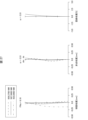
- FIG. 3 is a diagram schematically showing the optical configuration of the zoom lens of Example 1 at the wide-angle end when focusing at infinity.
- FIG. 3 is a diagram showing longitudinal aberration at the wide-angle end of the zoom lens of Example 1 when focusing at infinity.
- FIG. 3 is a diagram showing longitudinal aberration of the zoom lens of Example 1 at an intermediate focal length state when focusing at infinity.
- FIG. 3 is a diagram showing longitudinal aberration at the telephoto end of the zoom lens of Example 1 when focusing at infinity.
- 7 is a diagram schematically showing the optical configuration of the zoom lens of Example 2 at the wide-angle end when focusing at infinity.
- 13A and 13B are diagrams illustrating longitudinal aberration at the wide-angle end when the zoom lens of Example 2 is focused on an object at infinity.
- 7 is a diagram showing longitudinal aberration of the zoom lens of Example 2 at an intermediate focal length state when focusing at infinity.
- FIG. 7 is a diagram showing longitudinal aberration at the telephoto end of the zoom lens of Example 2 when focusing at infinity.
- FIG. 7 is a diagram schematically showing the optical configuration of the zoom lens of Example 3 at the wide-angle end when focusing at infinity.
- 13A and 13B are diagrams illustrating longitudinal aberration at the wide-angle end when the zoom lens of Example 3 is focused on an object at infinity.
- FIG. 7 is a diagram showing the longitudinal aberration of the zoom lens of Example 3 at an intermediate focal length state when focusing at infinity.
- 7 is a diagram showing longitudinal aberration at the telephoto end of the zoom lens of Example 3 when focusing at infinity;
- FIG. 7 is a diagram schematically showing the optical configuration of the zoom lens of Example 4 at the wide-angle end when focusing at infinity.
- FIG. 7 is a diagram showing longitudinal aberration at the wide-angle end of the zoom lens of Example 4 when focusing at infinity.
- FIG. 7 is a diagram showing longitudinal aberration of the zoom lens of Example 4 at an intermediate focal length state when focusing at infinity.
- 7 is a diagram showing longitudinal aberration at the telephoto end of the zoom lens of Example 4 when focusing at infinity.
- FIG. 7 is a diagram schematically showing the optical configuration of the zoom lens of Example 5 at the wide-angle end when focusing at infinity.
- FIG. 13 is a diagram showing longitudinal aberration at the wide-angle end when the zoom lens of Example 5 is focused on an object at infinity.
- FIG. 7 is a diagram showing longitudinal aberration of the zoom lens of Example 5 at an intermediate focal length state when focusing at infinity.
- FIG. 7 is a diagram showing longitudinal aberration at the telephoto end of the zoom lens of Example 5 when focusing at infinity.
- FIG. 13 is a diagram illustrating an optical configuration of a zoom lens according to a sixth embodiment at a wide-angle end when focused on infinity.
- FIG. 7 is a diagram showing longitudinal aberration at the wide-angle end of the zoom lens of Example 6 when focusing at infinity.
- FIG. 12 is a diagram showing longitudinal aberration of the zoom lens of Example 6 at an intermediate focal length state when focusing at infinity.
- FIG. 13 is a diagram showing longitudinal aberration at the telephoto end when the zoom lens of Example 6 is focused on infinity.
- FIG. 7 is a diagram schematically showing the optical configuration of the zoom lens of Example 7 at the wide-angle end when focusing at infinity.
- FIG. 7 is a diagram showing longitudinal aberration at the wide-angle end of the zoom lens of Example 7 when focusing at infinity.
- FIG. 12 is a diagram showing longitudinal aberration of the zoom lens of Example 7 at an intermediate focal length state when focusing at infinity.
- FIG. 7 is a diagram showing longitudinal aberration at the telephoto end of the zoom lens of Example 7 when focusing at infinity.
- FIG. 7 is a diagram schematically showing the optical configuration of the zoom lens of Example 8 at the wide-angle end when focusing at infinity.
- FIG. 9 is a diagram showing longitudinal aberration at the wide-angle end of the zoom lens of Example 8 when focusing at infinity.
- FIG. 12 is a diagram showing longitudinal aberration of the zoom lens of Example 8 at an intermediate focal length state when focusing at infinity.
- FIG. 7 is a diagram showing longitudinal aberration at the telephoto end of the zoom lens of Example 8 when focusing at infinity.
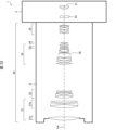
- 1 is a diagram schematically showing an example of the configuration of an imaging device according to an embodiment of the present invention.
- the present embodiment relates to a zoom lens and an imaging device suitable for an imaging device using a solid-state imaging device (CCD, CMOS, etc.) such as a digital still camera and a digital video camera.
- a solid-state imaging device CCD, CMOS, etc.
- the zoom lens and imaging device described below are one embodiment of the zoom lens and imaging device according to the present invention, and the zoom lens and imaging device according to the present invention are not limited to the following embodiments. Note that in this specification, "in order" means arranged adjacently unless otherwise specified.
- a zoom lens according to an embodiment of the present invention includes, in order from the object side, a front group having a negative refractive power and a rear group having a positive refractive power.
- a zoom lens according to an embodiment of the present invention may include only a front group and a rear group.
- the front group is a set of multiple lens groups on the object side that have negative refractive power as a whole
- the rear group is a set of multiple lens groups on the image side that have positive refractive power as a whole. is a set of lens groups having .
- the optical axis of the lens group closest to the image plane in the front group and the lens group closest to the object side in the rear group at the wide-angle end of the zoom lens are defined as the front group, and the set on the image plane side is defined as the rear group.
- a “lens group” includes one or more lenses.
- a “lens group” is one lens or a group of two or more lenses in which the distance between adjacent lens groups changes when changing the magnification between the wide-angle end and the telephoto end.
- the lens group includes a plurality of lenses, the plurality of lenses maintain a relative positional relationship during zooming between the wide-angle end and the telephoto end.
- the lens group may be configured to be movable on the optical axis or may be fixed.
- a "synthetic lens group” is a group of lenses determined according to the position on the optical axis and the overall refractive power.
- a composite lens group is composed of one or more lens groups. When the composite lens group consists of two or more lens groups, each lens group can be moved independently along the optical axis.
- a lens group may have one or more subgroups.
- a sub group is composed of one or more lenses in one lens group. In the case where the subgroup is composed of two or more lenses, it is composed of two or more lenses that are consecutively arranged along the optical axis.
- the sub-groups are fixed within the lens group. That is, the sub-group is configured such that it can move along the optical axis together with the lens group, but cannot move independently on the optical axis within the lens group.
- a subgroup may be identified as a lens or a set of two or more lenses that achieves a particular optical property, such as the refractive power of the entire subgroup, from the lenses in the lens group.
- the zoom lens may include a cemented lens.
- the number of lenses in a cemented lens is the number of lenses cemented together.
- Examples of the cemented lens include a cemented lens in which a plurality of lenses are integrated without an air gap.
- Another example of a cemented lens is a cemented lens that is made up of a plurality of lenses that are bonded together by an adhesive that is very thin and has a thickness that does not substantially affect optical performance. In this case, the adhesive layer does not count as a lens.
- a cemented lens in which two lenses are bonded together via an adhesive layer is counted as two lenses.
- the lens included in the zoom lens may include a compound lens in which one lens and resin are integrated.
- a compound lens in which one lens and resin are integrated is counted as one lens.
- the front group has negative refractive power as a whole.
- the front group includes, as a lens group and a composite lens group, in order from the object side, only a lens group G1 having a positive refractive power and a composite lens group Gn having a negative refractive power. It is preferable to arrange the lens group G1 having a positive refractive power closest to the object side from the viewpoint of providing a telephoto type refractive power arrangement and shortening the total optical length of the zoom lens compared to the focal length.
- Lens group G1 has positive refractive power.
- the lens group G1 has, as sub-groups, only a sub-group G1a having a positive refractive power and a sub-group G1b in order from the object side. This configuration is preferable from the viewpoint of reducing the diameter of the sub group G1b and from the viewpoint of reducing the weight of the lens group G1, which has the largest proportion of lens weight among the lens groups included in the zoom lens.
- the sub-group G1a has one or more lenses with positive refractive power.
- the sub group G1a may include two or more lenses having positive refractive power. It is preferable for the subgroup G1a to have two or less lenses having positive refractive power from the viewpoint of reducing the weight of the subgroup G1a and from the viewpoint of efficiently and easily lowering the height of the light rays incident on the subgroup G1b. Further, it is preferable that the sub group G1a does not include a lens having negative refractive power from the viewpoint of reducing the weight of the lens group G1.
- the sub group G1b includes one or more lenses with positive refractive power and one or more lenses with negative refractive power. It is preferable that the sub group G1b includes a lens having a positive refractive power and a lens having a negative refractive power from the viewpoint of correcting spherical aberration and chromatic aberration well and easily. It is preferable from the viewpoint of reducing the weight of the lens group G1 that one of the lenses having positive refractive power in the sub group G1b is disposed closest to the object side of the sub group G1b.
- the lens having a negative refractive power of the sub group G1b is made of a material having a higher specific gravity than the lens having a positive refractive power of the sub group G1a or the lens having a positive refractive power of the sub group G1b. Tend. Therefore, from the viewpoint of reducing the weight of the lens group G1, it is preferable that the air gap between the sub group G1a and the sub group G1b is the maximum air gap in the lens group G1.
- the composite lens group Gn has negative refractive power as a whole.
- the composition of the composite lens group Gn may be appropriately determined within a range in which the entire lens group has negative refractive power.
- the composite lens group Gn has one or more lens groups, and may be composed of only one lens group, or may be composed of a plurality of lens groups.
- the composite lens group Gn is composed of a plurality of lens groups. By changing the distance between adjacent lens groups during zooming between the wide-angle end and the telephoto end, spherical aberration and field curvature can be suppressed over the entire zoom range. It is also preferable from the viewpoint of easy correction.
- the plurality of lens groups may include at least one lens group having positive refractive power.
- the composite lens group Gn preferably has at least one lens with negative refractive power, and more preferably has two or more lenses with negative refractive power. Such a configuration is preferable from the viewpoint of providing the composite lens group Gn with a strong negative refractive power and obtaining a zoom lens with a high zoom ratio.
- the composite lens group Gn includes at least one lens having positive refractive power.
- the fact that the composite lens group Gn includes two or more lenses with negative refractive power and one or more lenses with positive refractive power allows for good correction of various aberrations, high zoom ratio, and high performance. This is preferable from the viewpoint of achieving both At this time, the lens closest to the object side of the composite lens group Gn is a lens having positive refractive power, which lowers the height of the light rays incident on the lens group arranged closer to the image plane than the composite lens group Gn. This is preferable because it contributes to miniaturization and weight reduction of the zoom lens as a whole.
- the rear group has positive refractive power as a whole.
- the rear group includes, in order from the object side, a composite lens group Gp having a positive refractive power and a lens group Gf having a negative refractive power.
- the rear group further includes a lens group Gr having a negative refractive power closer to the image plane than the lens group Gf.
- Such a configuration is preferable from the viewpoint of easily realizing a zoom lens with a short overall length, since the telephoto type refractive power arrangement can be made stronger.
- the rear group may be comprised only of the above-mentioned composite lens group Gp, lens group Gf, and lens group Gr, or may further include other lens groups.
- the rear group may have one or more lens groups between the lens group Gf and the lens group Gr.
- the rear group may include one or more lens groups on the image plane side of the lens group Gr.
- the composite lens group Gp has a positive refractive power as a whole.
- the composite lens group Gp has one or more lens groups, and may be composed of only one lens group, or may have multiple lens groups. When the composite lens group Gp is composed of multiple lens groups, the multiple lens groups may have at least one lens group having a negative refractive power.
- the composite lens group Gp When the composite lens group Gp is composed of a plurality of lens groups, it is preferable to have a lens group having a positive refractive power closest to the object side. Further, the composite lens group Gp includes, in order from the object side, a lens having a first positive refractive power, a lens having a second positive refractive power, a lens having a third positive refractive power, and a first lens having a positive refractive power. It is more preferable to have a lens with negative refractive power. Such a configuration is preferable from the viewpoint of strengthening the telephoto type refractive power arrangement and realizing miniaturization of the lens group and the aperture diameter arranged closer to the image plane than the composite lens group Gp.
- the composite lens group Gp has a vibration isolation group Gv that has negative refractive power and moves in a direction perpendicular to the optical axis to correct image blur.
- the anti-vibration group Gv is a collection of one or more lenses.
- the anti-vibration group Gv is arranged closer to the image plane than the first lens having negative refractive power, so that the angle of incidence of the axial light beam incident on the anti-vibration group Gv becomes gentler, and eccentricity during image stabilization is reduced. This is preferable from the viewpoint of suppressing the occurrence of aberrations.
- the vibration isolation group Gv be arranged closer to the image plane side from the viewpoint of realizing a smaller diameter of the vibration isolation group Gv.
- the configuration of the anti-vibration group Gv can be appropriately determined within a range in which the entire lens has negative refractive power. It is preferable that the anti-vibration group Gv is composed of two or less lenses from the viewpoint of realizing miniaturization of the anti-vibration drive mechanism. In addition, the fact that the anti-vibration group Gv is composed of only a cemented lens consisting of one lens with positive refractive power and one lens with negative refractive power reduces chromatic aberration during anti-vibration. This is preferable from the viewpoint of good correction.
- Lens group Gf is arranged at a position adjacent to the image plane side of composite lens group Gp. Such a configuration is preferable from the viewpoint of realizing miniaturization and weight reduction of the zoom lens as well as miniaturization of the focus mechanism.
- the lens group Gf has negative refractive power as a whole and includes at least one lens having negative refractive power.
- the configuration of the lens group Gf has negative refractive power as a whole, and can be appropriately determined within the range of having at least one lens having negative refractive power.
- the lens group Gf further includes a lens having positive refractive power from the viewpoint of suppressing aberration fluctuations over the entire object distance.
- the lens group Gf has a lens having a positive refractive power and a lens having a negative refractive power in order from the object side, from the viewpoint of realizing a reduction in size and weight of the lens group Gf.
- Lens group Gr is arranged on the image plane side of lens group Gf, and has negative refractive power.
- the lens group Gr is a plurality of lens groups having a negative refractive index arranged on the image plane side of the lens group Gf.
- this lens group has the strongest negative refractive power.
- the configuration of the lens group Gr can be appropriately determined within a range in which the entire lens group has negative refractive power.
- having the lens group Gr include two or more lenses with negative refractive power and one or more lenses with positive refractive power strengthens the telephoto type structure and reduces the overall length of the zoom lens. This is preferable from the viewpoint of realizing both shortening and high performance.
- the aperture diaphragm may be placed within the front group, within the rear group, or between the front group and the rear group. . Further, the aperture stop is preferably disposed in the rear group, and for example, may be disposed within the composite lens group Gp, or may be disposed between the composite lens group Gp and the lens group Gf. . It is preferable that the aperture stop is disposed in the rear group from the viewpoint of downsizing the aperture unit.
- the aperture diaphragm is placed within the composite lens group Gp or between the composite lens group Gp and the lens group Gf, the diameter of the incident light beam becomes smaller, thereby realizing miniaturization of the aperture diaphragm unit. It is preferable from the viewpoint of
- At least one of the one or more lens groups included in the composite lens group Gn moves on the optical axis toward the image plane side during zooming from the wide-angle end to the telephoto end.
- the composite lens group Gn has a plurality of lens groups, all the lens groups may move during zooming. It is preferable for the lens groups of the composite lens group Gn to move in this manner during zooming from the viewpoint of reducing the diameter of the lens groups after the composite lens group Gn at the telephoto end.
- the distance between the composite lens group Gp and the lens group Gf on the optical axis be widened at the middle of the zoom. It is preferable to move in this manner from the viewpoint that it becomes easy to satisfactorily correct the curvature of field over the entire zoom range.
- the lens group Gr When changing the magnification from the wide-angle end to the telephoto end, the lens group Gr may be configured not to move on the optical axis, or may be moved on the optical axis toward the object side.
- moving the lens group Gr with negative refractive power toward the object side on the optical axis can increase the zoom ratio, so it is possible to use a zoom lens with a high zoom ratio. This is preferable from the point of view of implementation.
- the lens group Gf moves on the optical axis.
- the lens group Gf preferably moves toward the image plane along the optical axis.
- Such a configuration is preferable in a zoom lens in which the focus group is closer to the image plane than the aperture stop, from the viewpoint of suppressing fluctuations in the aperture diameter from the infinity focus state to the closest focus state.
- the focus group in the zoom lens may further include lens groups other than lens group Gf.
- a zoom lens for example, one or more lens groups having positive or negative refractive power, which are arranged on the image plane side of the lens group Gf, are moved on the optical axis with a movement trajectory different from that of the lens group Gf. It is also possible to use a configuration in which focusing is performed using . In this way, the so-called floating focus method may be adopted for the zoom lens. Such a configuration is preferable from the viewpoint of better correcting spherical aberration and field curvature over the entire object distance.
- Equation (1) is an equation for appropriately setting the distance on the optical axis between the sub-group G1a and the sub-group G1b with respect to the total length of the lens group G1. Specifically, equation (1) calculates the distance on the optical axis between the lens surface closest to the object side of the lens group G1 and the lens surface closest to the image plane side of the lens group G1, This is a formula for appropriately setting the distance on the optical axis between the lens surface on the image plane side and the lens surface closest to the object side of the sub group G1b. It is preferable to satisfy the formula (1) from the viewpoint of reducing the weight of the lens group G1, which is the heaviest among the lens groups included in the zoom lens, and at the same time, satisfactorily correcting various aberrations.
- Dab/D1 When Dab/D1 is less than the lower limit of equation (1), the height of the light rays incident on subgroup G1b from the optical axis increases, which is mainly advantageous for correcting spherical aberration and chromatic aberration, but It may be difficult to achieve weight reduction. Furthermore, when Dab/D1 exceeds the upper limit of equation (1), it is advantageous to reduce the weight of the subgroup G1b, but it may be difficult to satisfactorily correct various aberrations.
- Dab/D1 is more preferably 0.34 or more, more preferably 0.36 or more, more preferably 0.38 or more, More preferably, it is 0.40 or more. From the viewpoint of satisfactorily correcting various aberrations, Dab/D1 is more preferably 0.72 or less, more preferably 0.69 or less, more preferably 0.66 or less, and 0. It is more preferably 63 or less, more preferably 0.60 or less, and even more preferably 0.57 or less.
- Equation (2) is an equation for appropriately setting the ratio between the back focus and the maximum image height at the wide-angle end when the zoom lens is focused at infinity. Specifically, equation (2) calculates the maximum image height at the wide-angle end when the zoom lens focuses at infinity to the lens surface closest to the image plane at the wide-angle end when the zoom lens focuses at infinity. This is a formula for appropriately setting the distance on the optical axis from to the image plane. If another optical element is interposed between the lens surface closest to the image plane and the image plane, the optical distance of the other optical element is the air equivalent distance on the optical axis of the optical element. . Examples of the other optical element include a glass flat member having parallel surfaces, a filter, and the like. Examples of the flat glass member include dummy glass and cover glass. It is preferable to satisfy formula (2) from the viewpoint of ensuring a back focus suitable for exchanging zoom lenses at the wide-angle end and from the viewpoint of realizing a compact zoom lens.
- BFw/Yw is less than the lower limit of equation (2)
- the back focus may become too short and the inclination angle of the light incident on the image sensor with respect to the optical axis may become too large.
- it is necessary to increase the exit pupil diameter so it may be difficult to reduce the diameter of the lens group located closest to the image plane of the zoom lens.
- BFw/Yw exceeds the upper limit of equation (2)
- the back focus becomes too long, and it may be difficult to downsize the zoom lens at the wide-angle end.
- BFw/Yw is more preferably 0.70 or more, more preferably 0.75 or more, and 0.70 or more. It is more preferably 80 or more, more preferably 0.85 or more, and even more preferably 0.90 or more. Further, from the viewpoint of realizing miniaturization of the zoom lens at the wide-angle end, BFw/Yw is more preferably 4.20 or less, more preferably 3.90 or less, and 3.60 or less. is more preferable, and more preferably 3.30 or less.
- Equation (3) is an equation for appropriately setting the ratio of the focal length of the sub group G1a to the focal length of the lens group G1.
- equation (3) is an equation for appropriately setting the focal length of the sub group G1a with respect to the focal length of the lens group G1. It is preferable to satisfy formula (3) from the viewpoint of being able to satisfactorily correct various aberrations while reducing the weight of the zoom lens.
- f1a/f1 is less than the lower limit of equation (3), the focal length of subgroup G1a becomes too small relative to the focal length of lens group G1, making it difficult to satisfactorily correct spherical aberration and chromatic aberration. There is. Furthermore, if f1a/f1 exceeds the upper limit of equation (3), it may be difficult to reduce the size of the sub-group G1b, which may make it difficult to reduce the weight of the entire zoom lens. .
- f1a/f1 is more preferably 0.85 or more, more preferably 0.90 or more, more preferably 0.95 or more, More preferably, it is 1.00 or more.
- f1a/f1 is more preferably 1.65 or less, more preferably 1.60 or less, It is more preferably 1.55 or less, more preferably 1.50 or less, more preferably 1.45 or less, and even more preferably 1.40 or less.
- Equation (4) is an equation for appropriately setting the ratio between the height of the axial ray at the telephoto end of the sub-group G1a when focusing at infinity and the height of the axial ray of the sub-group G1b.
- Equation (4) is based on the height from the optical axis of the marginal ray passing through the lens surface closest to the object at the telephoto end when the sub group G1a is focused at infinity.
- This is a formula for appropriately setting the height from the optical axis of the marginal ray that passes through the lens surface closest to the object at the telephoto end during long distance focusing. It is preferable to satisfy the expression (4) from the viewpoint of reducing the weight of the lens group G1, which is the heaviest among the lens groups included in the zoom lens, and at the same time, satisfactorily correcting various aberrations.
- the subgroup G1b can be made smaller and lighter, but it may be difficult to satisfactorily correct mainly spherical aberration and chromatic aberration. Furthermore, if Hbt/Hat exceeds the upper limit of equation (4), it will be difficult to achieve sufficient miniaturization of subgroup G1b, and therefore it will be difficult to achieve sufficient weight reduction of the entire zoom lens. It may happen.
- Hbt/Hat is more preferably 0.68 or more, more preferably 0.71 or more, more preferably 0.74 or more, It is more preferably 0.77 or more, and even more preferably 0.80 or more. Further, from the viewpoint of realizing weight reduction of the entire zoom lens, Hbt/Hat is more preferably 0.92 or less, more preferably 0.91 or less, and preferably 0.90 or less. More preferably, it is 0.89 or less, and even more preferably 0.88 or less.
- Equation (5) is an equation for appropriately setting the ratio between the focal length of the lens group Gr and the focal length at the telephoto end when the zoom lens is focused at infinity.
- equation (5) is an equation for appropriately setting the focal length of the lens group Gr with respect to the focal length at the telephoto end when the zoom lens is focused at infinity. It is preferable to satisfy formula (5) from the viewpoint of ensuring a telephoto type refractive power arrangement and easily realizing miniaturization of the entire zoom lens.
- the telephoto type refractive power arrangement becomes weak, and it may be difficult to realize miniaturization of the overall length. For example, if the positive refractive power of the lens group G1 is strengthened to ensure a telephoto configuration, it may be difficult to correct chromatic aberration particularly well. Furthermore, when fr/ft exceeds the upper limit of equation (5), the telephoto type refractive power arrangement becomes too strong, and it may become difficult to satisfactorily correct the strong curvature of field in the over direction.
- fr/ft is more preferably -0.80 or more, more preferably -0.75 or more, and more preferably -0.70 or more. , more preferably -0.65 or more, more preferably -0.60 or more, more preferably -0.55 or more, more preferably -0.50 or more. Furthermore, from the viewpoint of satisfactorily correcting strong overdirection field curvature, fr/ft is more preferably -0.08 or less, more preferably -0.13 or less, and -0.18 It is more preferably below, more preferably -0.23 or less, even more preferably -0.28 or less.
- Equation (6) 1.01 ⁇ rt/ ⁇ rw ⁇ 1.50 (6) however, ⁇ rt: lateral magnification at the telephoto end when the lens group Gr is focused at infinity ⁇ rw: lateral magnification at the wide-angle end when the lens group Gr is focused at infinity
- Equation (6) is an equation for appropriately setting the ratio between the lateral magnification at the telephoto end and the lateral magnification at the wide-angle end when the lens group Gr is focused at infinity. Specifically, equation (6) is used to appropriately set the lateral magnification at the telephoto end when the lens group Gr is focused at infinity relative to the lateral magnification at the wide-angle end when the lens group Gr is focused at infinity.
- the formula is It is preferable to satisfy formula (6) from the viewpoint of appropriately setting the zoom ratio of the lens group Gr and achieving both high performance and high zoom ratio.
- the lens group Gr may not be able to change the magnification, and it may be difficult to achieve a high variable magnification.
- the amount of movement of at least one lens group included in the composite lens group Gn becomes large, which may make it difficult to reduce the overall length of the zoom lens.
- ⁇ rt/ ⁇ rw exceeds the upper limit of equation (6), the load on the lens group Gr for changing the magnification becomes too large, and it may become difficult to satisfactorily correct the curvature of field.
- ⁇ rt/ ⁇ rw is more preferably 1.03 or more, more preferably 1.05 or more, and even more preferably 1.07 or more. From the viewpoint of satisfactorily correcting field curvature, ⁇ rt/ ⁇ rw is more preferably 1.40 or less, more preferably 1.30 or less, and even more preferably 1.25 or less.
- Equation (7) is an equation for appropriately setting the ratio between the refractive power of the anti-vibration group Gv and the refractive power of the composite lens group Gp at the telephoto end.
- equation (7) is an equation for appropriately setting the absolute value of the focal length of the image stabilization group Gv with respect to the focal length of the composite lens group Gp at the telephoto end. It is preferable to satisfy formula (7) from the viewpoint of controlling the drive amount of the vibration isolation group Gv within an appropriate range during vibration isolation and suppressing aberrations that occur during vibration isolation.
- /fpt is more preferably 0.70 or more, more preferably 0.80 or more, and 0.90 It is more preferably 1.00 or more, and more preferably 1.00 or more. Further, from the viewpoint of realizing miniaturization of the entire zoom lens,
- Equation (8) is a formula for appropriately setting the ratio of the total optical length at the telephoto end when the zoom lens is focused at infinity and the focal length at the telephoto end when the zoom lens is focused at infinity.
- equation (8) is an equation for appropriately setting the optical total length at the telephoto end when the zoom lens is focused at infinity relative to the focal length at the telephoto end when the zoom lens is focused at infinity. It is.
- the "optical total length" is the total length on the optical axis from the object-side lens surface of the lens closest to the object among the lenses constituting the zoom lens to the image plane. Satisfying equation (8) is preferable from the viewpoint of realizing a compact and lightweight zoom lens with a short overall optical length relative to the focal length.
- Lt/ft is less than the lower limit of equation (8), the total optical length of the zoom lens may become too short relative to the focal length, making it difficult to satisfactorily correct various aberrations. Furthermore, the sensitivity of each lens to errors increases, and the optical performance may deteriorate too much due to manufacturing errors.
- Lt/ft exceeds the upper limit of equation (8), the amount of movement of each lens group during zooming increases in order to obtain a predetermined zoom ratio, and the amount of movement of each lens group along the optical axis increases. This may lead to an increase in the size of the variable power drive mechanism, making it difficult to realize a desired compact and lightweight zoom lens.
- Lt/ft is more preferably 0.38 or more, more preferably 0.41 or more, and more preferably 0.44 or more. is more preferable, and more preferably 0.47 or more. Further, from the viewpoint of realizing a compact and lightweight zoom lens, Lt/ft is more preferably 0.68 or less, more preferably 0.66 or less, and even more preferably 0.64 or less. It is preferably 0.62 or less, more preferably 0.60 or less.
- Equation (9) is the relationship between the lateral magnification of the lens group Gf at the telephoto end when focused at infinity and the lateral magnification at the telephoto end of all the lens groups on the image side than the lens group Gf when focused at infinity. This is a formula for appropriately setting the relationship
- is more preferably 5.4 or more, more preferably 5.8 or more, and 6 It is more preferably .2 or more, more preferably 6.6 or more, and even more preferably 7.0 or more. Further,
- Equation (10) is an equation for appropriately setting the Abbe number at the d-line of at least one lens with positive refractive power included in the subgroup G1a.
- the sub group G1a includes a plurality of lenses having positive refractive power, it is sufficient that at least one lens having positive refractive power satisfies Expression (10). Satisfying formula (10) is preferable from the viewpoint of achieving a zoom lens that has high optical performance with good correction of chromatic aberration, and at the same time reducing the weight of the zoom lens.
- vdp is less than the lower limit of equation (10)
- the correction of chromatic aberration at the telephoto end may be insufficient, and it may be difficult to realize a zoom lens with high optical performance.
- vdp exceeds the upper limit of equation (10)
- the Abbe number at the d-line of the lens having positive refractive power included in subgroup G1a may become too large.
- a glass material with a large Abbe number at the d-line tends to have a large specific gravity, and the sub group G1a tends to be composed of the lens with the largest diameter among the lenses constituting the zoom lens. Therefore, the specific gravity has a large effect on the weight of the lens. Therefore, it may be difficult to reduce the weight of the subgroup G1a.
- vdp is more preferably 58.0 or more, more preferably 61.0 or more, and even more preferably 63.0 or more. Further, from the viewpoint of realizing weight reduction of the subgroup G1a, vdp is more preferably 75.0 or less, and more preferably 72.0 or less.
- Equation (11) is a formula for appropriately setting the anomalous dispersion ⁇ PgF1b at the g-line and F-line of at least one lens having negative refractive power in the sub-group G1b.
- the sub-group G1b has multiple lenses having negative refractive power, at least one lens having negative refractive power only needs to satisfy equation (11).
- anomaly dispersion represents the deviation of the partial dispersion ratio from a reference line when a straight line passing through the coordinates of glass material C7, which has a partial dispersion ratio of 0.5393 and ⁇ d of 60.49, and the coordinates of glass material F2, which has a partial dispersion ratio of 0.5829 and ⁇ d of 36.30, is used as the reference line in a coordinate system with the partial dispersion ratios of the g-line and F-line on the vertical axis and the Abbe number ⁇ d for the d-line on the horizontal axis.
- chromatic aberration is corrected by using a low-dispersion glass material for lenses with positive refractive power, and using a high-dispersion glass material for lenses with negative refractive power.
- the reference line is a straight line passing through the coordinates of the partial dispersion ratios of glass materials C7 and F2 and the Abbe number ( ⁇ d) for the d-line, the deviation from the reference line of the partial dispersion ratio of glass materials on the low dispersion side is positive. Located in the direction.
- ⁇ PgF1b is less than the lower limit of equation (11)
- excessive chromatic aberration correction may cause the curvature of the lens with negative refractive power of sub group G1b to become too strong. If the curvature of the lens having negative refractive power included in the sub group G1b becomes strong, the influence on the lens weight becomes large, and it may become difficult to realize a weight reduction of the zoom lens. Furthermore, if ⁇ PgF1b exceeds the upper limit of equation (11), correction of chromatic aberration on the short wavelength side at the telephoto end may become insufficient, making it difficult to realize a zoom lens with high optical performance.
- ⁇ PgF1b is more preferably -0.010 or more, more preferably -0.009 or more, more preferably -0.008 or more, More preferably, it is -0.007 or more. Further, from the viewpoint of realizing a zoom lens with high optical performance, ⁇ PgF1b is more preferably -0.002 or less, more preferably -0.003 or less, and -0.004 or less. is more preferable, and more preferably ⁇ 0.005 or less.
- Equation (12) is an equation for appropriately setting the ratio between the focal length of the composite lens group Gp at the telephoto end and the focal length of the zoom lens at the telephoto end when focusing at infinity.
- equation (12) is an equation for appropriately setting the focal length of the composite lens group Gp at the telephoto end with respect to the focal length at the telephoto end when the zoom lens is focused at infinity. Satisfying equation (12) is preferable from the viewpoint of making it easy to satisfactorily correct various aberrations and realizing a compact and lightweight zoom lens with a short overall length.
- fpt/ft is more preferably 0.06 or more, more preferably 0.07 or more, and more preferably 0.08 or more. , more preferably 0.09 or more. Further, from the viewpoint of shortening the total length of the zoom lens at the telephoto end, fpt/ft is more preferably 0.18 or less, more preferably 0.16 or less, and more preferably 0.14 or less. More preferred.
- Equation (13) is an equation for appropriately setting the ratio between the focal length of the lens group G1 and the focal length at the wide-angle end when the zoom lens is focused at infinity.
- equation (13) is an equation for appropriately setting the focal length of the lens group G1 with respect to the focal length at the wide-angle end when the zoom lens is focused at infinity. Satisfying equation (13) is preferable from the viewpoint of realizing a zoom lens having high optical performance while realizing miniaturization of the zoom lens at the wide-angle end.
- f1/fw is more preferably 0.50 or more, more preferably 0.60 or more, and even more preferably 0.70 or more. It is preferably 0.80 or more, more preferably 0.90 or more. Further, from the viewpoint of shortening the optical total length at the wide-angle end, f1/fw is more preferably 2.70 or less, more preferably 2.40 or less, and even more preferably 2.10 or less. It is preferably 1.90 or less, and more preferably 1.90 or less.
- Equation (14) expresses the amount of movement of the lens group having positive refractive power in the composite lens group Gp relative to the amount of movement of the lens group having negative refractive power in the composite lens group Gn when zooming from the wide-angle end to the telephoto end. This is a formula for appropriately setting the ratio of the amount of movement of .
- the composite lens group Gn includes a plurality of lens groups having negative refractive power, it is sufficient that one or more lens groups having negative refractive power satisfy Expression (14).
- the composite lens group Gp includes a plurality of lens groups having positive refractive power, it is sufficient that one or more lens groups having positive refractive power satisfy Expression (14).
- the sign of each movement amount is positive when moving toward the object side on the optical axis when changing the magnification from the wide-angle end to the telephoto end. It is preferable to satisfy formula (14) from the viewpoint of reducing the diameter of the rear group and from the viewpoint of realizing weight reduction of the zoom lens as a whole.
- Xp/(-Xn) is more preferably 0.90 or less, more preferably 0.80 or less, and even more preferably 0.75 or less. It is preferably 0.70 or less, and more preferably 0.70 or less.
- the lower limit of Xp/(-Xn) can be determined as appropriate within the range in which the effects of the present invention can be obtained.
- Xp/(-Xn) is more preferably 0.10 or more, more preferably 0.15 or more, and even more preferably 0.20 or more.
- Equation (15) is an equation for appropriately setting the Abbe number at the d-line of the lens having negative refractive power included in sub group G1b.
- the sub group G1b includes a plurality of lenses having negative refractive power
- at least one of the lenses having negative refractive power only needs to satisfy Expression (15). It is preferable to satisfy formula (15) from the viewpoint of realizing a zoom lens having high optical performance with good correction of chromatic aberration and reducing the weight of the zoom lens.
- vdn is less than the lower limit of equation (15)
- correction of chromatic aberration at the telephoto end may be insufficient, making it difficult to realize a zoom lens with high optical performance.
- vdn exceeds the upper limit of equation (15)
- the curvature of the lens having negative refractive power of subgroup G1b may become too strong in order to obtain a secondary spectrum of equivalent chromatic aberration.
- the sub group G1b tends to be composed of lenses with the second largest diameter after the sub group G1a among the lenses that make up the zoom lens. , the influence on the lens weight becomes large, and it may become difficult to realize the weight reduction of the sub group G1b.
- vdn is more preferably 37.0 or more, more preferably 39.0 or more, and even more preferably 41.0 or more. Further, from the viewpoint of realizing weight reduction of the subgroup G1b, vdn is more preferably 53.0 or less, more preferably 51.0 or less, more preferably 49.0 or less, Vdn is more preferably 47.0 or less.
- the imaging device includes the zoom lens according to the embodiment described above, and an imaging element that is provided on the image plane side of the zoom lens and converts an optical image formed by the zoom lens into an electrical signal.
- the image sensor there is no limitation to the image sensor, and a solid-state image sensor such as a CCD (Charge Coupled Device) sensor or a CMOS (Complementary Metal Oxide Semiconductor) sensor can be used as the image sensor, and a silver halide film or the like can also be used.
- the imaging device according to this embodiment is suitable for imaging devices using the above solid-state imaging device, such as digital cameras and video cameras. Further, the imaging device may be a fixed-lens imaging device in which the lens is fixed to a housing, or may be an interchangeable-lens imaging device such as a single-lens reflex camera or a mirrorless single-lens camera.
- the zoom lens according to this embodiment can ensure a back focus suitable for an interchangeable lens system. Therefore, it is suitable for an imaging device such as a single-lens reflex camera that is equipped with an optical finder, a phase difference sensor, and a reflex mirror for branching light between them.
- an imaging device such as a single-lens reflex camera that is equipped with an optical finder, a phase difference sensor, and a reflex mirror for branching light between them.
- FIG. 33 is a diagram schematically showing an example of the configuration of an imaging device according to this embodiment.
- the mirrorless single-lens camera 1 includes a main body 2 and a lens barrel 3 that is detachable from the main body 2.
- the mirrorless single-lens camera 1 is one aspect of an imaging device.
- the lens barrel 3 has a zoom lens 30.
- the zoom lens 30 includes a first lens group 31 , a second lens group 32 , a third lens group 33 , a fourth lens group 34 , and a fifth lens group 35 .
- the zoom lens 30 is configured to satisfy, for example, the above-mentioned equations (1) and (2).
- the first lens group 31 includes a first sub-a group 31a and a first sub-b group 31b. Note that a diaphragm 36 is arranged within the third lens group 33.
- the first lens group 31 has positive refractive power and corresponds to the above-mentioned lens group G1.
- the second lens group 32 has negative refractive power and corresponds to the above-mentioned composite lens group Gn.
- the third lens group 33 has positive refractive power and corresponds to the above-mentioned composite lens group Gp.
- the fourth lens group 34 has negative refractive power and corresponds to the above-mentioned lens group Gf.
- the fifth lens group 35 has negative refractive power and corresponds to the above-mentioned lens group Gr.
- the first sub-group a 31a has positive refractive power and corresponds to the above-described sub-group G1a.
- the first sub-group b 31b has positive refractive power and corresponds to the above-described sub-group G1b. Further, the first lens group 31 and the second lens group 32 correspond to the above-mentioned front group. The third lens group 33, the fourth lens group 34, and the fifth lens group 35 correspond to the aforementioned rear group. The sub-group 33v corresponds to the above-mentioned anti-vibration group Gv.
- the main body 2 has a CCD sensor 21 as an image sensor and a cover glass 22.
- the CCD sensor 21 is arranged in the main body 2 at a position where the optical axis OA of the zoom lens 30 in the lens barrel 3 mounted on the main body 2 is the central axis.
- the main body 2 may have a parallel flat plate having no substantial refractive power.
- the imaging device includes an image processing unit that electrically processes the captured image data acquired by the image sensor to change the shape of the captured image, and a device for processing the captured image data in the image processing unit. It is more preferable to include an image correction data holding unit that holds image correction data, an image correction program, etc. used for the image correction.
- the shape of the captured image formed on the imaging plane tends to be distorted.
- the correction may be performed by, for example, storing distortion correction data for correcting distortion in the shape of the captured image in advance in the image correction data holding unit, and using the distortion correction data held in the image correction data holding unit in the image processing unit. This can be implemented by using According to such an imaging device, the zoom lens can be further downsized, beautiful captured images can be obtained, and the entire imaging device can be downsized.
- the image correction data storage unit store magnification chromatic aberration correction data in advance. It is also preferable that the image processing unit performs magnification chromatic aberration correction of the captured image using the magnification chromatic aberration correction data stored in the image correction data storage unit.
- magnification chromatic aberration i.e., color distortion aberration
- the zoom lens according to aspect 1 of the present invention has, in order from the object side, a front group having a negative refractive power and a rear group having a positive refractive power, and the front group serves as a lens group and a composite lens group.
- the front group serves as a lens group and a composite lens group.
- the rear group includes, in order from the object side, a composite lens group Gp having a positive refractive power.
- the rear group further has a lens group Gr having a negative refractive power closer to the image plane than the lens group Gf
- the composite lens group Gn includes one or more lenses.
- the composite lens group Gp has one or more lens groups, and when zooming between the wide-angle end and the telephoto end, the distance between adjacent lens groups on the optical axis changes, and during focusing, the lens group Gf moves on the optical axis, and the lens group G1 has only subgroups G1a and G1b having positive refractive power in order from the object side, and the subgroup G1b has one or more lenses.
- the zoom lens includes a lens having a positive refractive power and one or more lenses having a negative refractive power, and satisfies the following formula. 0.32 ⁇ Dab/D1 ⁇ 0.75 (1) 0.50 ⁇ BFw/Yw ⁇ 4.50 (2) however, Dab: Distance on the optical axis between the lens surface closest to the image side of sub group G1a and the lens surface closest to the object side of sub group G1b D1: The distance between the lens surface closest to the object side of lens group G1 and the lens group Distance on the optical axis between the lens surface closest to the image plane of G1 BFw: Distance on the optical axis from the lens surface closest to the image plane to the image plane at the wide-angle end when focusing on infinity of the zoom lens Yw: Maximum image height at the wide-angle end when focusing on infinity of the zoom lens
- a zoom lens according to a second aspect of the present invention is a zoom lens according to the first aspect, in which one of the lenses having positive refractive power in the sub group G1b is disposed closest to the object side in the sub group G1b. Good too.
- the zoom lens according to aspect 3 of the present invention may be a zoom lens in which the lens group G1 is fixed during zooming between the wide-angle end and the telephoto end in the above-mentioned aspect 1 or 2.
- the zoom lens according to aspect 4 of the present invention may be any one of aspects 1 to 3 described above, in which at least one of the lens groups in the composite lens group Gn moves along the optical axis toward the image plane when changing magnification from the wide-angle end to the telephoto end.
- the lens group Gr moves on the optical axis toward the object side during zooming from the wide-angle end to the telephoto end. It can also be used as a zoom lens.
- the zoom lens according to aspect 6 of the present invention may be a zoom lens that satisfies the following formula in any one of aspects 1 to 5 above. 0.80 ⁇ f1a/f1 ⁇ 1.70 (3) however, f1a: Focal length of sub group G1a f1: Focal length of lens group G1
- the zoom lens according to aspect 7 of the present invention may be a zoom lens that satisfies the following formula in any one of aspects 1 to 6 above. 0.65 ⁇ Hbt/Hat ⁇ 0.93 (4) however, Hat: Height from the optical axis of the marginal ray passing through the lens surface closest to the object at the telephoto end when the sub group G1a is focused at infinity Hbt: Height at the telephoto end when the sub group G1b is focused at infinity Height from the optical axis of the marginal ray passing through the lens surface closest to the object
- the zoom lens according to aspect 8 of the present invention may be a zoom lens that satisfies the following expression in any one of aspects 1 to 7 above. -0.90 ⁇ fr/ft ⁇ -0.03 (5) however, fr: Focal length of lens group Gr ft: Focal length at the telephoto end when focusing on infinity of the zoom lens
- the zoom lens according to aspect 9 of the present invention may be a zoom lens that satisfies the following formula in any one of aspects 1 to 8 above. 1.01 ⁇ rt/ ⁇ rw ⁇ 1.50 (6) however, ⁇ rt: Lateral magnification of the lens group Gr at the telephoto end when focused at infinity ⁇ rw: Lateral magnification of the lens group Gr at the wide-angle end when focused at infinity
- the composite lens group Gp has negative refractive power and moves in a direction perpendicular to the optical axis to prevent image blur. It is also possible to use a zoom lens that has an anti-vibration group Gv to be corrected and satisfies the following equation. 0.65 ⁇
- the zoom lens according to aspect 11 of the present invention may be a zoom lens that satisfies the following formula in any one of aspects 1 to 10 above. 0.35 ⁇ Lt/ft ⁇ 0.70 (8) however, Lt: Total optical length of the zoom lens at the telephoto end when focusing on infinity ft: Focal length of the zoom lens at the telephoto end when focusing on infinity
- the zoom lens according to aspect 12 of the present invention may be a zoom lens that satisfies the following formula in any one of aspects 1 to 11 above. 5.0 ⁇
- the zoom lens according to aspect 13 of the present invention may be a zoom lens that satisfies the following formula in any one of aspects 1 to 12 described above. 55.0 ⁇ vdp ⁇ 78.0 (10) however, vdp: Abbe number at d-line of at least one lens with positive refractive power included in subgroup G1a
- the zoom lens according to aspect 14 of the present invention may be a zoom lens that satisfies the following formula in any one of aspects 1 to 13 above. -0.012 ⁇ PgF1b ⁇ -0.001 (11) however, ⁇ PgF1b: Anomalous dispersion of at least one lens having negative refractive power included in subgroup G1b
- the zoom lens according to aspect 15 of the present invention may be a zoom lens that satisfies the following formula in any one of aspects 1 to 14 described above. 0.05 ⁇ fpt/ft ⁇ 0.20 (12) however, fpt: Focal length at the telephoto end of the composite lens group Gp ft: Focal length at the telephoto end when focusing on infinity of the zoom lens
- the zoom lens according to aspect 16 of the present invention may be a zoom lens that satisfies the following formula in any one of aspects 1 to 15 above. 0.40 ⁇ f1/fw ⁇ 3.00 (13) however, f1: Focal length of lens group G1 fw: Focal length at the wide-angle end when focusing on infinity of the zoom lens
- An imaging device includes the zoom lens according to any one of aspects 1 to 16, and an optical image formed by the zoom lens provided on the image plane side of the zoom lens.
- the image capturing device may include an image capturing element that performs conversion.
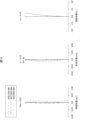
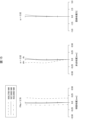
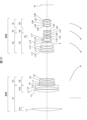
- FIG. 1 is a diagram schematically showing the optical configuration of the zoom lens of Example 1 at the wide-angle end when focusing on infinity.
- the zoom lens of Example 1 includes, in order from the object side, a first lens group G1 having a positive refractive power, a second lens group G2 having a negative refractive power, and a third lens group G3 having a positive refractive power. , a fourth lens group G4 having negative refractive power, and a fifth lens group G5 having negative refractive power.
- the first lens group G1 includes a first sub-a group G1a having a positive refractive power and a first sub-b group G1b having a positive refractive power.
- the third lens group G3 includes a sub-group Gv having negative refractive power.
- An aperture stop S is arranged within the third lens group G3.
- "IP" shown in FIG. 1 is an image plane.
- the first lens group G1 is composed of, in order from the object side, a biconvex lens L1, a cemented lens of a biconvex lens L2 and a biconcave lens L3, and a biconvex lens L4.
- the first sub-a group G1a is composed of a lens L1.
- the first sub-b group G1b is composed of a cemented lens of a lens L2 and a lens L3, and a lens L4.
- the second lens group G2 is composed of, in order from the object side, a cemented lens of a biconvex lens L5 and a biconcave lens L6, a biconcave lens L7, and a biconcave lens L8.
- the third lens group G3 includes, in order from the object side, a biconvex lens L9, a positive meniscus lens L10 with a convex surface facing the object side, a cemented lens of a biconvex lens L11 and a biconcave lens L12, a biconvex lens L13, and the object side.
- a three-piece cemented lens consisting of a negative meniscus lens L14 with a convex surface facing toward the object side, a biconvex lens L15, and a biconcave lens L16, a cemented lens with a positive meniscus lens L17 and a biconcave lens L18 with a concave surface facing the object side, and a biconvex lens L19. configured.
- the cemented lens of lenses L17 and L18 constitutes a sub-group Gv.
- the sub group Gv is arranged so as to be movable in a direction perpendicular to the optical axis so as to correct image blur.
- the fourth lens group G4 is composed of a negative meniscus lens L20 with a convex surface facing the object side.
- the fifth lens group G5 includes, in order from the object side, a cemented lens of a biconcave lens L21 and a biconvex lens L22, a cemented lens of a biconvex lens L23 and a biconcave lens L24, and a negative meniscus lens L25 with a concave surface facing the object side. configured.
- the negative meniscus lens L25 is a composite resin type aspherical lens in which a composite resin film molded into an aspherical shape is attached to the object side surface.
- the first lens group G1 corresponds to the above-mentioned lens group G1.
- the first sub-group a G1a corresponds to the above-mentioned sub-group G1a
- the first sub-group B G1b corresponds to the above-mentioned sub-group G1b.
- the second lens group G2 corresponds to the above-mentioned composite lens group Gn.
- the third lens group G3 corresponds to the above-mentioned composite lens group Gp.
- the fourth lens group G4 corresponds to the aforementioned lens group Gf.
- the fifth lens group G5 corresponds to the above-mentioned lens group Gr.
- the first lens group G1 and the second lens group G2 correspond to the above-mentioned front group.
- the third lens group G3, the fourth lens group G4, and the fifth lens group G5 correspond to the aforementioned rear group.
- the sub-group Gv corresponds to the above-mentioned anti-vibration group Gv.
- the zoom lens of Example 1 performs a zooming operation by changing the distance between adjacent lens groups on the optical axis.
- the arrows shown below each lens group at the wide-angle end indicate the locus of movement of each lens group when moving from the wide-angle end to the telephoto end.
- the first lens group G1 is fixed
- the second lens group G2 moves on the optical axis toward the image plane
- the third lens group G3, fourth lens group G4
- the fifth lens group G5 moves on the optical axis toward the object side.
- the fourth lens group G4 moves on the optical axis.
- Table 1 shows surface data of the zoom lens of Example 1.
- "surface number” is the order of the lens surface counted from the object side
- "r” is the radius of curvature of the lens surface
- “d” is the number on the optical axis of the lens surface.
- "vd” represents the Abbe number for the d-line.
- the symbol “S” indicates that the lens is a diaphragm
- the symbol “ASPH” indicates that the lens surface is an aspherical surface.
- the indications such as “d(7)” and “d(14)" in the "d” column indicate that the interval on the optical axis of the lens surface is a variable interval that changes when changing the magnification or focusing. means.
- No. 1 to 7 are surface numbers of the first lens group G1; 8 to 14 are surface numbers of the second lens group G2.
- No. 15 to 33 are surface numbers of the third lens group G3; 22 represents an aperture stop.
- No. 34 and 35 are surface numbers of the fourth lens group G4; 36 to 44 are surface numbers of the fifth lens group G5.
- the surface number of the object surface is "0", which is 1 smaller than the minimum value in the table.
- the surface number of the image plane is 1 larger than the maximum value in the table, and is "45" in this example.
- Table 2 shows a specification table of the zoom lens of Example 1.
- Table 2 shows a specification table of the zoom lens of Example 1.
- numerical values at the wide-angle end, intermediate focal length state, and telephoto end are shown in order from the left side.
- "f” represents the focal length of the zoom lens when focusing at infinity
- "FNo.” represents the F number
- " ⁇ " represents the half angle of view
- "Y” represents the maximum image height.
- "d(n)" (n is an integer) represents a variable interval on the optical axis of the zoom lens during zooming.
- Table 3 is a table showing aspherical coefficients of each aspherical surface in the zoom lens of Example 1.
- the aspheric coefficients in the table are values when each aspheric shape is defined by the following formula.
- [Formula] z ch 2 / [1+ ⁇ 1-(1+k)c 2 h 2 ⁇ 1/2 ]+A4h 4 +A6h 6 +A8h 8 +A10h 10 +A12h 12
- z is the displacement amount of the aspherical surface in the optical axis direction from the reference plane perpendicular to the optical axis
- c is the curvature (1/r)
- h is the height from the optical axis
- k is a conical coefficient
- An (n is an integer) is an n-order aspherical coefficient. Note that the aspheric coefficients of surface numbers that are not displayed are 0.
- Table 4 shows the focal length of each lens group that makes up the zoom lens of Example 1.
- FIGS. 2, 3, and 4 are diagrams showing the longitudinal aberration of the zoom lens of Example 1 at the wide-angle end, intermediate focal length state, and infinity focusing at the telephoto end, respectively.
- the longitudinal aberrations shown in each figure are spherical aberration (SA (mm)), astigmatism (AST (mm)), and distortion aberration (DIS (%)) in order from the left side as viewed from the drawing. The same applies to other embodiments.
- the vertical axis is the F number and the horizontal axis is defocus.
- the vertical axis is the half angle of view, and the horizontal axis is defocus.
- the solid line shows the astigmatism in the sagittal image plane (indicated by ds in the figure) for the d-line
- the broken line shows the astigmatism in the meridional plane (indicated by dm in the figure) for the d-line.
- the vertical axis is the half angle of view, and the horizontal axis is %.
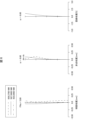
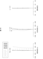
- FIG. 5 is a diagram schematically showing the optical configuration of the zoom lens of Example 2 at the wide-angle end when focusing on infinity.
- 6, 7, and 8 are diagrams showing the longitudinal aberration of the zoom lens of Example 2 at the wide-angle end, intermediate focal length state, and telephoto end when focusing at infinity, respectively.
- the zoom lens of Example 2 includes, in order from the object side, a first lens group G1 having a positive refractive power, a second lens group G2 having a negative refractive power, and a third lens group G3 having a negative refractive power.
- the first lens group G1 includes a first sub-a group G1a having a positive refractive power and a first sub-b group G1b having a positive refractive power.
- the fourth lens group G4 includes a sub-group Gv having negative refractive power.
- An aperture stop S is arranged within the fourth lens group G4.
- the first lens group G1 is composed of, in order from the object side, a biconvex lens L1, a cemented lens of a biconvex lens L2 and a biconcave lens L3, and a biconvex lens L4.
- the first sub-a group G1a is composed of a lens L1.
- the first sub-b group G1b is composed of a cemented lens of a lens L2 and a lens L3, and a lens L4.
- the second lens group G2 is composed of, in order from the object side, a cemented lens of a biconvex lens L5 and a biconcave lens L6, and a biconcave lens L7.
- the third lens group G3 is composed of a biconcave lens L8.
- the fourth lens group G4 includes, in order from the object side, a biconvex lens L9, a positive meniscus lens L10 with a convex surface facing the object side, a cemented lens of a biconvex lens L11 and a biconcave lens L12, a biconvex lens L13, and a biconvex lens L13 on the object side.
- Consists of a three-piece cemented lens consisting of a negative meniscus lens L14 with a convex surface facing, a biconvex lens L15, and a biconcave lens L16, a cemented lens with a positive meniscus lens L17 and a biconcave lens L18 with a concave surface facing the object side, and a biconvex lens L19.
- the cemented lens of lenses L17 and L18 constitutes a sub-group Gv.
- the sub group Gv is arranged so as to be movable in a direction perpendicular to the optical axis so as to correct image blur.
- the fifth lens group G5 is composed of a negative meniscus lens L20 with a convex surface facing the object side.
- the sixth lens group G6 includes, in order from the object side, a cemented lens of a biconcave lens L21 and a biconvex lens L22, a cemented lens of a biconvex lens L23 and a biconcave lens L24, and a negative meniscus lens L25 with a concave surface facing the object side. configured.
- the negative meniscus lens L25 is a composite resin type aspherical lens in which a composite resin film molded into an aspherical shape is attached to the object side surface.
- the first lens group G1 corresponds to the aforementioned lens group G1.
- the first sub-group a G1a corresponds to the above-mentioned sub-group G1a
- the first sub-group B G1b corresponds to the above-mentioned sub-group G1b.
- the second lens group G2 and the third lens group G3 correspond to the above-mentioned composite lens group Gn.
- the fourth lens group G4 corresponds to the above-mentioned composite lens group Gp.
- the fifth lens group G5 corresponds to the above-mentioned lens group Gf.
- the sixth lens group G6 corresponds to the above-mentioned lens group Gr.
- the first lens group G1, the second lens group G2, and the third lens group G3 correspond to the above-mentioned front group.
- the fourth lens group G4, the fifth lens group G5, and the sixth lens group G6 correspond to the aforementioned rear group.
- the sub-group Gv corresponds to the above-mentioned anti-vibration group Gv.
- the zoom lens of Example 2 performs a zooming operation by changing the distance between adjacent lens groups on the optical axis.
- the first lens group G1 is fixed
- the second lens group G2 and the third lens group G3 move on the optical axis toward the image plane
- the fourth lens group G4 moves on the fifth lens group G5 and the sixth lens group G6 move on the optical axis toward the object side.
- the fifth lens group G5 moves on the optical axis.
- Table 5 is a table of surface data of the zoom lens of Example 2.
- No. 1 to 7 are surface numbers of the first lens group G1; 8 to 12 are surface numbers of the second lens group G2; 13 and 14 are surface numbers of the third lens group G3.
- No. 15 to 33 are surface numbers of the fourth lens group G4; 22 represents an aperture stop.
- No. 34 and 35 are surface numbers of the fifth lens group G5.
- 36 to 44 are surface numbers of the sixth lens group G6.
- Table 6 shows a specification table of the zoom lens of Example 2.
- Table 7 is a table showing aspherical coefficients of each aspherical surface in the zoom lens of Example 2.
- Table 8 shows the focal length of each lens group constituting the zoom lens of Example 2.
- FIG. 9 is a diagram schematically showing the optical configuration of the zoom lens of Example 3 at the wide-angle end when focusing on infinity.
- FIGS. 10, 11, and 12 are diagrams showing longitudinal aberrations of the zoom lens of Example 3 at the wide-angle end, intermediate focal length state, and telephoto end when focusing on infinity.
- the zoom lens of Example 3 includes, in order from the object side, a first lens group G1 having a positive refractive power, a second lens group G2 having a positive refractive power, and a third lens group G3 having a negative refractive power.
- the first lens group G1 includes a first sub-a group G1a having a positive refractive power and a first sub-b group G1b having a positive refractive power.
- the fourth lens group G4 includes a sub-group Gv having negative refractive power.
- An aperture stop S is arranged within the fourth lens group G4.
- the first lens group G1 is composed of, from the object side, a biconvex lens L1, a cemented lens of a biconvex lens L2 and a biconcave lens L3, and a biconvex lens L4.
- the first sub-a group G1a is composed of lens L1.
- the first sub-b group G1b is composed of a cemented lens of lens L2 and lens L3, and lens L4.
- the second lens group G2 is composed of a biconvex lens L5 and a biconcave lens L6 in order from the object side.
- the third lens group G3 is composed of, in order from the object side, a negative meniscus lens L7 with a convex surface facing the object side, and a negative meniscus lens L8 with a concave surface facing the object side.
- the fourth lens group G4 includes, in order from the object side, a biconvex lens L9, a positive meniscus lens L10 with a convex surface facing the object side, a cemented lens of a biconvex lens L11 and a biconcave lens L12, a biconvex lens L13, and the object side.
- a three-piece cemented lens consisting of a negative meniscus lens L14 with a convex surface facing toward the object side, a biconvex lens L15, and a biconcave lens L16, a cemented lens with a positive meniscus lens L17 and a biconcave lens L18 with a concave surface facing the object side, and a biconvex lens L19. configured.
- the cemented lens of lenses L17 and L18 constitutes a sub-group Gv.
- the sub group Gv is arranged so as to be movable in a direction perpendicular to the optical axis so as to correct image blur.
- the fifth lens group G5 is composed of a negative meniscus lens L20 with a convex surface facing the object side.
- the sixth lens group G6 includes, in order from the object side, a cemented lens of a biconcave lens L21 and a biconvex lens L22, a cemented lens of a biconvex lens L23 and a biconcave lens L24, and a negative meniscus lens L25 with a concave surface facing the object side. configured.
- the negative meniscus lens L25 is a composite resin type aspherical lens in which a composite resin film molded into an aspherical shape is attached to the object side surface.
- the first lens group G1 corresponds to the lens group G1 described above.
- the first sub-a group G1a corresponds to the sub-group G1a described above
- the first sub-b group G1b corresponds to the sub-group G1b described above.
- the second lens group G2 and the third lens group G3 correspond to the composite lens group Gn described above.
- the fourth lens group G4 corresponds to the composite lens group Gp described above.
- the fifth lens group G5 corresponds to the lens group Gf described above.
- the sixth lens group G6 corresponds to the lens group Gr described above.
- the first lens group G1, the second lens group G2, and the third lens group G3 correspond to the front group described above.
- the fourth lens group G4, the fifth lens group G5, and the sixth lens group G6 correspond to the rear group described above.
- the sub-group Gv corresponds to the vibration isolation group Gv described above.
- the zoom lens of Example 3 performs a zooming operation by changing the distance between adjacent lens groups on the optical axis.
- the first lens group G1 is fixed
- the second lens group G2 and the third lens group G3 move on the optical axis toward the image plane
- the fourth lens group G4 moves on the fifth lens group G5 and the sixth lens group G6 move on the optical axis toward the object side.
- the fifth lens group G5 moves on the optical axis.
- Table 9 is a table of surface data of the zoom lens of Example 3.
- No. 1 to 7 are surface numbers of the first lens group G1; 8 to 11 are surface numbers of the second lens group G2; 12 to 15 are surface numbers of the third lens group G3.
- No. 16 to 34 are surface numbers of the fourth lens group G4; 23 represents an aperture stop.
- No. 35 and 36 are surface numbers of the fifth lens group G5; 37 to 45 are surface numbers of the sixth lens group G6.
- Table 10 shows the specification table of the zoom lens of Example 3.
- Table 11 is a table showing aspherical coefficients of each aspherical surface in the zoom lens of Example 3.
- Table 12 shows the focal length of each lens group constituting the zoom lens of Example 3.
- FIG. 13 is a diagram schematically showing the optical configuration of the zoom lens of Example 4 at the wide-angle end when focusing on infinity.
- FIGS. 14, 15, and 16 are diagrams showing longitudinal aberrations of the zoom lens of Example 4 at the wide-angle end, intermediate focal length state, and telephoto end when focusing on infinity.
- the zoom lens of Example 4 includes, in order from the object side, a first lens group G1 having a positive refractive power, a second lens group G2 having a negative refractive power, and a third lens group G3 having a positive refractive power.
- the first lens group G1 includes a first sub-a group G1a having a positive refractive power and a first sub-b group G1b having a negative refractive power.
- the fourth lens group G4 includes a sub-group Gv having negative refractive power.
- An aperture stop S is arranged between the third lens group G3 and the fourth lens group G4.
- the first lens group G1 is composed of, in order from the object side, a biconvex lens L1, a positive meniscus lens L2 with a convex surface facing the object side, and a cemented lens of a biconvex lens L3 and a biconcave lens L4.
- the first sub-a group G1a is composed of a lens L1.
- the first sub-b group G1b is composed of a cemented lens of a lens L2 and a lens L3, and a lens L4.
- the second lens group G2 includes, in order from the object side, a cemented lens consisting of a positive meniscus lens L5 with a convex surface facing the object side, a negative meniscus lens L6 with a convex surface facing the object side, and a positive meniscus lens with a concave surface facing the object side. It is composed of a cemented lens of a lens L7 and a biconcave lens L8, and a biconcave lens L9.
- the third lens group G3 is composed of, in order from the object side, a positive meniscus lens L10 with a convex surface facing the object side, a biconvex lens L11, and a cemented lens of a biconvex lens L12 and a biconcave lens L13.
- the fourth lens group G4 includes, in order from the object side, a biconvex lens L14, a negative meniscus lens L15 with a convex surface facing the object side, a three-piece cemented lens consisting of a biconvex lens L16, a biconcave lens L17, and a concave surface facing the object side.
- the lens is composed of a cemented lens of a positive meniscus lens L18 and a biconcave lens L19, and a cemented lens of a negative meniscus lens L20 with a convex surface facing the object side and a biconvex lens L21.
- the cemented lens of lenses L18 and L19 constitutes a sub-group Gv.
- the sub group Gv is arranged so as to be movable in a direction perpendicular to the optical axis so as to correct image blur.
- the fifth lens group G5 is composed of, in order from the object side, a cemented lens consisting of a biconvex lens L22 and a biconcave lens L23.
- the sixth lens group G6 includes, in order from the object side, a cemented lens of a negative meniscus lens L24 with a convex surface facing the object side and a biconvex lens L25, a cemented lens of a biconvex lens L26 and a biconcave lens L27, and a cemented lens with a concave surface facing the object side. It is composed of a negative meniscus lens L28 that is directed toward the lens.
- the negative meniscus lens L28 is a composite resin type aspherical lens in which a composite resin film molded into an aspherical shape is attached to the object side surface.
- the first lens group G1 corresponds to the aforementioned lens group G1.
- the first sub-group a G1a corresponds to the above-mentioned sub-group G1a
- the first sub-group B G1b corresponds to the above-mentioned sub-group G1b.
- the second lens group G2 corresponds to the above-mentioned composite lens group Gn.
- the third lens group G3 and the fourth lens group G4 correspond to the above-mentioned composite lens group Gp.
- the fifth lens group G5 corresponds to the above-mentioned lens group Gf.
- the sixth lens group G6 corresponds to the above-mentioned lens group Gr.
- the first lens group G1 and the second lens group G2 correspond to the above-mentioned front group.
- the third lens group G3, the fourth lens group G4, the fifth lens group G5, and the sixth lens group G6 correspond to the aforementioned rear group.
- the sub-group Gv corresponds to the above-mentioned anti-vibration group Gv.
- the zoom lens of Example 4 performs a zooming operation by changing the distance between adjacent lens groups on the optical axis.
- the first lens group G1 is fixed
- the second lens group G2 moves on the optical axis toward the image plane
- the third lens group G3, fourth lens group G4 moves on the fifth lens group G5 and the sixth lens group G6 move on the optical axis toward the object side.
- the fifth lens group G5 moves on the optical axis.
- Table 13 is a table of surface data of the zoom lens of Example 4.
- No. 1 to 7 are surface numbers of the first lens group G1; 8 to 15 are surface numbers of the second lens group G2.
- No. 16 to 22 are surface numbers of the third lens group G3; 23 represents an aperture stop, and
- No. 24 to 35 are surface numbers of the fourth lens group G4.
- No. 36 to 38 are surface numbers of the fifth lens group G5, and No. 39 to 47 are surface numbers of the sixth lens group G6.
- Table 14 shows a specification table of the zoom lens of Example 4.
- Table 15 is a table showing aspherical coefficients of each aspherical surface in the zoom lens of Example 4.
- Table 16 shows the focal length of each lens group constituting the zoom lens of Example 4.
- FIG. 17 is a diagram schematically showing the optical configuration of the zoom lens of Example 5 at the wide-angle end when focusing on infinity.
- FIGS. 18, 19, and 20 are diagrams showing longitudinal aberrations of the zoom lens of Example 5 at the wide-angle end, intermediate focal length state, and telephoto end when focusing on infinity.
- the zoom lens of Example 5 includes, in order from the object side, a first lens group G1 having a positive refractive power, a second lens group G2 having a negative refractive power, and a third lens group G3 having a positive refractive power.
- the first lens group G1 includes a first sub-a group G1a having a positive refractive power and a first sub-b group G1b having a positive refractive power.
- the fourth lens group G4 includes a sub-group Gv having negative refractive power.
- An aperture stop S is arranged between the third lens group G3 and the fourth lens group G4.
- the first lens group G1 is composed of, from the object side, a biconvex lens L1, a biconvex lens L2, and a cemented lens of a biconvex lens L3 and a biconcave lens L4.
- the first sub-group a G1a is composed of lens L1.
- the first sub-group b G1b is composed of a cemented lens of lens L2 and lens L3, and lens L4.
- the second lens group G2 includes, in order from the object side, a cemented lens consisting of a positive meniscus lens L5 with a convex surface facing the object side, a negative meniscus lens L6 with a convex surface facing the object side, and a positive meniscus lens with a concave surface facing the object side. It is composed of a cemented lens of a lens L7 and a biconcave lens L8, and a negative meniscus lens L9 with a concave surface facing the object side.
- the third lens group G3 is composed of, in order from the object side, a positive meniscus lens L10 with a convex surface facing the object side, a biconvex lens L11, and a cemented lens of a biconvex lens L12 and a biconcave lens L13.
- the fourth lens group G4 is a three-piece cemented lens consisting of, in order from the object side, a positive meniscus lens L14 with a concave surface facing the object side, a negative meniscus lens L15 with a convex surface facing the object side, a biconvex lens L16, and a biconcave lens L17. , a cemented lens of a positive meniscus lens L18 with a concave surface facing the object side and a biconcave lens L19, and a cemented lens of a negative meniscus lens L20 with a convex surface facing the object side and a biconvex lens L21.
- the cemented lens of lenses L18 and L19 constitutes a sub-group Gv.
- the sub group Gv is arranged so as to be movable in a direction perpendicular to the optical axis so as to correct image blur.
- the fifth lens group G5 is composed of a cemented lens of a biconvex lens L22 and a biconcave lens L23 in order from the object side.
- the sixth lens group G6 includes, in order from the object side, a cemented lens of a negative meniscus lens L24 with a convex surface facing the object side and a biconvex lens L25, a cemented lens of a biconvex lens L26 and a biconcave lens L27, and a cemented lens with a concave surface facing the object side. It is composed of a negative meniscus lens L28 that is directed toward the lens.
- the negative meniscus lens L28 is a composite resin type aspherical lens in which a composite resin film molded into an aspherical shape is attached to the object side surface.
- the first lens group G1 corresponds to the aforementioned lens group G1.
- the first sub-group a G1a corresponds to the above-mentioned sub-group G1a
- the first sub-group B G1b corresponds to the above-mentioned sub-group G1b.
- the second lens group G2 corresponds to the above-mentioned composite lens group Gn.
- the third lens group G3 and the fourth lens group G4 correspond to the above-mentioned composite lens group Gp.
- the fifth lens group G5 corresponds to the above-mentioned lens group Gf.
- the sixth lens group G6 corresponds to the above-mentioned lens group Gr.
- the first lens group G1 and the second lens group G2 correspond to the above-mentioned front group.
- the third lens group G3, the fourth lens group G4, the fifth lens group G5, and the sixth lens group G6 correspond to the aforementioned rear group.
- the sub-group Gv corresponds to the above-mentioned anti-vibration group Gv.
- the zoom lens of Example 5 performs a zooming operation by changing the distance between adjacent lens groups on the optical axis.
- the first lens group G1 is fixed
- the second lens group G2 moves on the optical axis toward the image plane
- the third lens group G3, fourth lens group G4 moves on the fifth lens group G5 and the sixth lens group G6 move on the optical axis toward the object side.
- the fifth lens group G5 moves on the optical axis.
- Table 17 is a table of surface data of the zoom lens of Example 5.
- No. 1 to 7 are surface numbers of the first lens group G1; 8 to 15 are surface numbers of the second lens group G2.
- No. 16 to 22 are surface numbers of the third lens group G3; 23 represents an aperture stop, and
- No. 24 to 35 are surface numbers of the fourth lens group G4.
- No. 36 to 38 are surface numbers of the fifth lens group G5, and No. 39 to 47 are surface numbers of the sixth lens group G6.
- Table 18 shows the specifications of the zoom lens of Example 5.
- Table 19 shows the aspheric coefficients of each aspheric surface in the zoom lens of Example 5.
- Table 20 shows the focal length of each lens group that constitutes the zoom lens of Example 5.
- FIG. 21 is a diagram schematically showing the optical configuration of the zoom lens of Example 6 at the wide-angle end when focusing on infinity.
- FIGS. 22, 23, and 24 are diagrams showing longitudinal aberrations of the zoom lens of Example 6 at the wide-angle end, intermediate focal length state, and telephoto end when focusing at infinity, respectively.
- the zoom lens of Example 6 includes, in order from the object side, a first lens group G1 having a positive refractive power, a second lens group G2 having a negative refractive power, and a third lens group G3 having a positive refractive power. , a fourth lens group G4 having negative refractive power, and a fifth lens group G5 having negative refractive power.
- the first lens group G1 includes a first sub-a group G1a having a positive refractive power and a first sub-b group G1b having a positive refractive power.
- the third lens group G3 includes a sub-group Gv having negative refractive power.
- An aperture stop S is arranged within the third lens group G3.
- the first lens group G1 is composed of, in order from the object side, a biconvex lens L1, a biconvex lens L2, and a cemented lens of a biconvex lens L3 and a biconcave lens L4.
- the first sub-a group G1a is composed of a lens L1.
- the first sub-b group G1b is composed of a cemented lens of a lens L2 and a lens L3, and a lens L4.
- the second lens group G2 is composed of, in order from the object side, a cemented lens of a biconvex lens L5 and a biconcave lens L6, a cemented lens of a positive meniscus lens L7 with its concave surface facing the object side and a biconcave lens L8, and a biconcave lens L9.
- the third lens group G3 includes, in order from the object side, a positive meniscus lens L10 with a convex surface facing the object side, a biconvex lens L11, a cemented lens of a biconvex lens L12 and a biconcave lens L13, and a concave surface facing the object side.
- a three-piece cemented lens consisting of a positive meniscus lens L14, a negative meniscus lens L15 with a convex surface facing the object side, a biconvex lens L16, and a biconcave lens L17, and a positive meniscus lens L18 with a concave surface facing the object side and a biconcave lens L19.
- the cemented lens of lenses L18 and L19 constitutes a sub-group Gv.
- the sub group Gv is arranged so as to be movable in a direction perpendicular to the optical axis so as to correct image blur.
- the fourth lens group G4 is composed of, from the object side, a cemented lens consisting of a positive meniscus lens L22 with its concave surface facing and a biconcave lens L23.
- the fifth lens group G5 includes, in order from the object side, a cemented lens of a negative meniscus lens L24 with a convex surface facing the object side and a biconvex lens L25, a cemented lens of a biconvex lens L26 and a biconcave lens L27, and a cemented lens with a concave surface facing the object side. It is composed of a negative meniscus lens L28 that is directed toward the lens.
- the negative meniscus lens L28 is a composite resin type aspherical lens in which a composite resin film molded into an aspherical shape is attached to the object side surface.
- the first lens group G1 corresponds to the aforementioned lens group G1.
- the first sub-group a G1a corresponds to the above-mentioned sub-group G1a
- the first sub-group B G1b corresponds to the above-mentioned sub-group G1b.
- the second lens group G2 corresponds to the above-mentioned composite lens group Gn.
- the third lens group G3 corresponds to the above-mentioned composite lens group Gp.
- the fourth lens group G4 corresponds to the aforementioned lens group Gf.
- the fifth lens group G5 corresponds to the above-mentioned lens group Gr.
- the first lens group G1 and the second lens group G2 correspond to the above-mentioned front group.
- the third lens group G3, the fourth lens group G4, and the fifth lens group G5 correspond to the aforementioned rear group.
- the sub-group Gv corresponds to the above-mentioned anti-vibration group Gv.
- the zoom lens of Example 6 performs a zooming operation by changing the distance between adjacent lens groups on the optical axis.
- the first lens group G1 is fixed
- the second lens group G2 moves on the optical axis toward the image plane
- the third lens group G3, fourth lens group G4
- the fifth lens group G5 moves on the optical axis toward the object side.
- the fourth lens group G4 moves on the optical axis.
- Table 21 is a table of surface data of the zoom lens of Example 6.
- No. 1 to 7 are surface numbers of the first lens group G1; 8 to 15 are surface numbers of the second lens group G2.
- No. 16 to 35 are surface numbers of the third lens group G3; 23 represents an aperture stop.
- No. 36 to 38 are surface numbers of the fourth lens group G4.
- No. 39 to 47 are surface numbers of the fifth lens group G5.
- Table 22 shows a specification table of the zoom lens of Example 6.
- Table 23 is a table showing aspherical coefficients of each aspherical surface in the zoom lens of Example 6.
- Table 24 shows the focal length of each lens group constituting the zoom lens of Example 6.
- FIG. 25 is a diagram schematically showing the optical configuration of the zoom lens of Example 7 at the wide-angle end when focusing on infinity.
- 26, 27, and 28 are diagrams showing the longitudinal aberration of the zoom lens of Example 7 at the wide-angle end, intermediate focal length state, and telephoto end when focusing at infinity, respectively.
- the zoom lens of Example 7 includes, in order from the object side, a first lens group G1 having a positive refractive power, a second lens group G2 having a negative refractive power, and a third lens group G3 having a positive refractive power. , a fourth lens group G4 having negative refractive power, and a fifth lens group G5 having negative refractive power.
- the first lens group G1 includes a first sub-a group G1a having a positive refractive power and a first sub-b group G1b having a positive refractive power.
- the third lens group G3 includes a sub-group Gv having negative refractive power.
- An aperture stop S is arranged within the third lens group G3.
- the first lens group G1 is composed of, in order from the object side, a biconvex lens L1, a cemented lens of a biconvex lens L2 and a biconcave lens L3, and a positive meniscus lens L4 with a convex surface facing the object side.
- the first sub-a group G1a is composed of a lens L1.
- the first sub-b group G1b is composed of a cemented lens of a lens L2 and a lens L3, and a lens L4.
- the second lens group G2 is composed of, in order from the object side, a cemented lens of a biconvex lens L5 and a biconcave lens L6, a biconcave lens L7, and a biconcave lens L8.
- the third lens group G3 includes, in order from the object side, a biconvex lens L9, a positive meniscus lens L10 with a convex surface facing the object side, a cemented lens of a biconvex lens L11 and a biconcave lens L12, a biconvex lens L13, and a biconvex lens L13 on the object side.
- a three-piece cemented lens consisting of a negative meniscus lens L14 with a convex surface facing, a biconvex lens L15, a negative meniscus lens L16 with a concave surface facing the object side, and a cemented positive meniscus lens L17 with a concave surface facing the object side and a biconcave lens L18.
- the cemented lens of lenses L17 and L18 constitutes a sub-group Gv.
- the sub group Gv is arranged so as to be movable in a direction perpendicular to the optical axis so as to correct image blur.
- the fourth lens group G4 is composed of a negative meniscus lens L20 with its convex surface facing the object side.
- the fifth lens group G5 includes, in order from the object side, a cemented lens of a biconcave lens L21 and a biconvex lens L22, a cemented lens of a biconvex lens L23 and a biconcave lens L24, and a negative meniscus lens L25 with a concave surface facing the object side. configured.
- the negative meniscus lens L25 is a composite resin type aspherical lens in which a composite resin film molded into an aspherical shape is attached to the object side surface.
- the first lens group G1 corresponds to the aforementioned lens group G1.
- the first sub-group a G1a corresponds to the above-mentioned sub-group G1a
- the first sub-group B G1b corresponds to the above-mentioned sub-group G1b.
- the second lens group G2 corresponds to the above-mentioned composite lens group Gn.
- the third lens group G3 corresponds to the above-mentioned composite lens group Gp.
- the fourth lens group G4 corresponds to the aforementioned lens group Gf.
- the fifth lens group G5 corresponds to the above-mentioned lens group Gr.
- the first lens group G1 and the second lens group G2 correspond to the above-mentioned front group.
- the third lens group G3, the fourth lens group G4, and the fifth lens group G5 correspond to the aforementioned rear group.
- the sub-group Gv corresponds to the above-mentioned anti-vibration group Gv.
- the zoom lens of Example 7 performs a zooming operation by changing the distance between adjacent lens groups on the optical axis.
- the second lens group G2 moves on the optical axis toward the image plane
- the first lens group G1, third lens group G3, fourth lens group G4, and fifth lens Group G5 moves on the optical axis toward the object side.
- the fourth lens group G4 moves on the optical axis.
- Table 25 is a table of surface data for the zoom lens of Example 7.
- No. 1 to 7 are surface numbers for the first lens group G1
- No. 8 to 14 are surface numbers for the second lens group G2
- No. 15 to 33 are surface numbers for the third lens group G3, and
- No. 22 represents the aperture stop.
- No. 34 and 35 are surface numbers for the fourth lens group G4, and No. 36 to 44 are surface numbers for the fifth lens group G5.
- Table 26 shows a specification table of the zoom lens of Example 7.
- Table 27 is a table showing aspherical coefficients of each aspherical surface in the zoom lens of Example 7.
- Table 28 shows the focal length of each lens group constituting the zoom lens of Example 7.
- FIG. 29 is a diagram schematically showing the optical configuration of the zoom lens of Example 8 at the wide-angle end when focusing on infinity.
- FIGS. 30, 31, and 32 are diagrams showing longitudinal aberrations of the zoom lens of Example 8 at the wide-angle end, intermediate focal length state, and telephoto end when focusing on infinity.
- the zoom lens of Example 8 includes, in order from the object side, a first lens group G1 having a positive refractive power, a second lens group G2 having a negative refractive power, and a third lens group G3 having a positive refractive power.
- the first lens group G1 includes a first sub-a group G1a having a positive refractive power and a first sub-b group G1b having a positive refractive power.
- the third lens group G3 includes a sub-group Gv having negative refractive power.
- An aperture stop S is arranged within the third lens group G3.
- the first lens group G1 is composed of, in order from the object side, a biconvex lens L1, a biconvex lens L2, and a cemented lens of a biconvex lens L3 and a biconcave lens L4.
- the first sub-a group G1a is composed of a lens L1.
- the first sub-b group G1b is composed of a cemented lens of a lens L2 and a lens L3, and a lens L4.
- the second lens group G2 includes, in order from the object side, a cemented lens consisting of a positive meniscus lens L5 with a convex surface facing the object side, a negative meniscus lens L6 with a convex surface facing the object side, and a positive meniscus lens with a concave surface facing the object side. It is composed of a cemented lens of a lens L7 and a biconcave lens L8, and a biconcave lens L9.
- the third lens group G3 includes, in order from the object side, a biconvex lens L10, a biconvex lens L11, a cemented lens of a biconvex lens L12 and a biconcave lens L13, a biconvex lens L14, and a negative meniscus lens with a convex surface facing the object side.
- the cemented lens of lenses L18 and L19 constitutes a sub-group Gv.
- the sub group Gv is arranged so as to be movable in a direction perpendicular to the optical axis so as to correct image blur.
- the fourth lens group G4 is composed of, in order from the object side, a cemented lens of a positive meniscus lens L22 with a concave surface and a biconcave lens L23.
- the fifth lens group G5 includes, in order from the object side, a cemented lens of a negative meniscus lens L24 with a convex surface facing the object side and a biconvex lens L25, a cemented lens of a biconvex lens L26 and a biconcave lens L27, and a cemented lens with a concave surface facing the object side. It is composed of a negative meniscus lens L28 that is directed toward the lens.
- the negative meniscus lens L28 is a composite resin type aspherical lens in which a composite resin film molded into an aspherical shape is attached to the object side surface.
- the sixth lens group G6 is composed of a biconvex lens L29.
- the first lens group G1 corresponds to the lens group G1 described above.
- the first sub-a group G1a corresponds to the sub-group G1a described above
- the first sub-b group G1b corresponds to the sub-group G1b described above.
- the second lens group G2 corresponds to the composite lens group Gn described above.
- the third lens group G3 corresponds to the composite lens group Gp described above.
- the fourth lens group G4 corresponds to the lens group Gf described above.
- the fifth lens group G5 corresponds to the lens group Gr described above.
- the first lens group G1 and the second lens group G2 correspond to the front group described above.
- the third lens group G3, the fourth lens group G4, the fifth lens group G5, and the sixth lens group G6 correspond to the rear group described above.
- the sub-group Gv corresponds to the vibration isolation group Gv described above.
- the zoom lens of Example 8 performs a magnification change operation by changing the distance on the optical axis between adjacent lens groups.
- the first lens group G1 and the sixth lens group are fixed, the second lens group G2 moves on the optical axis toward the image surface, and the third lens group G3, the fourth lens group G4, and the fifth lens group G5 move on the optical axis toward the object side.
- the fourth lens group G4 moves on the optical axis.
- Table 29 is a table of surface data for the zoom lens of Example 8.
- No. 1 to 7 are surface numbers for the first lens group G1
- No. 8 to 15 are surface numbers for the second lens group G2
- No. 16 to 35 are surface numbers for the third lens group G3, and
- No. 23 represents the aperture stop.
- No. 36 to 38 are surface numbers for the fourth lens group G4,
- No. 39 to 47 are surface numbers for the fifth lens group G5, and No. 48 and 49 are surface numbers for the sixth lens group G6.
- Table 30 shows the specification table of the zoom lens of Example 8.
- Table 31 is a table showing aspherical coefficients of each aspherical surface in the zoom lens of Example 8.
- Table 32 shows the focal length of each lens group constituting the zoom lens of Example 8.
- Example 1 Example 2
- Example 3 Example 4 Equation (1) Dab/D1 0.466 0.464 0.472 0.509 Formula (2) BFw/Yw 2.247 2.121 2.229 2.117 Equation (3) f1a/f1 1.112 1.209 1.209 0.934 Equation (4) Hbt/Hat 0.863 0.863 0.839 Equation (5) fr/ft -0.375 -0.445 -0.364 -0.838 Equation (6) ⁇ rt/ ⁇ rw 1.084 1.086 1.090 1.035 Equation (7)
Landscapes
- Physics & Mathematics (AREA)
- General Physics & Mathematics (AREA)
- Optics & Photonics (AREA)
- Nonlinear Science (AREA)
- Lenses (AREA)
Abstract
Provided are a zooming lens and an imaging device that are small and light-weight, and have high optical performance. The zooming lens (30) comprises, in order from the object side, a negative front group and a positive rear group. The front group includes, in order from the object side, a positive lens group G1 (G1) and a negative composite lens group Gn (G2). The rear group includes a positive composite lens group Gp (G3), a negative lens group Gf (G4), and a negative lens group Gr (G5). The zooming lens (30) have specific optical characteristics expressed by two specific expressions.
Description
本発明は、ズームレンズ及び撮像装置に関する。
The present invention relates to a zoom lens and an imaging device.
近年、デジタルスチルカメラ及びデジタルビデオカメラ等の固体撮像素子を用いた撮像装置が普及している。それに伴い、これらの撮像装置の光学系の高性能化及び小型化が進み、小型の撮像装置システムが急速に普及してきている。特に、焦点距離の長い望遠系のズームレンズでは光学系の高性能化と共に、小型化及び軽量化に対する要望が高まっている。
In recent years, imaging devices using solid-state imaging devices, such as digital still cameras and digital video cameras, have become widespread. Along with this, the optical systems of these imaging devices have become more sophisticated and smaller, and compact imaging device systems are rapidly becoming popular. In particular, for telephoto zoom lenses with long focal lengths, there is a growing demand for higher performance optical systems as well as smaller size and lighter weight.
上記のようなズームレンズには、ズーム比が4倍程度あり、35mm判換算したときの望遠端における焦点距離が800mm程度あり、F値が6.3程度のズームレンズが知られている(例えば、特許文献1参照)。当該ズームレンズでは、従来よりも長い望遠端の焦点距離を有しながらも、当該ズームレンズのテレフォト比が0.6前後であり、全長の小型化が図られている。
The above-mentioned zoom lenses have a zoom ratio of about 4 times, a focal length of about 800 mm at the telephoto end when converted to 35 mm size, and a zoom lens with an F value of about 6.3 (for example, , see Patent Document 1). Although the zoom lens has a longer focal length at the telephoto end than conventional lenses, the telephoto ratio of the zoom lens is around 0.6, and the overall length of the zoom lens is reduced.
ところで、望遠系のズームレンズでは、ズームレンズ全体の重量に対して、最も物体側に配置される第1レンズ群の重量が占める割合が高く支配的である。したがって、ズームレンズ全体の小型化及び軽量化を実現するためには、第1レンズ群の軽量化が有効である。また、ズームレンズ全体の軽量化と高性能化とを両立するためには、第1レンズ群のレンズ構成、パワー配置、及び硝材等を適切に設定することが有効である。
In telephoto zoom lenses, the weight of the first lens group, which is located closest to the object, accounts for a large proportion of the overall weight of the zoom lens and is therefore dominant. Therefore, reducing the weight of the first lens group is effective in achieving a compact and lightweight zoom lens as a whole. Also, in order to achieve both a lightweight and high-performance zoom lens as a whole, it is effective to appropriately set the lens configuration, power arrangement, glass material, etc. of the first lens group.
この点、特許文献1に記載のズームレンズの第1レンズ群の構成は、物体側から順に、第1負レンズと、第1正レンズと、第2正レンズからなる構成である。このように、最も物体側に配置されるレンズは、負の屈折力を有している。このため、特許文献1に記載のズームレンズでは、第1レンズ群の軽量化の観点から検討の余地が残されている。
In this regard, the configuration of the first lens group of the zoom lens described in Patent Document 1 is composed of, in order from the object side, a first negative lens, a first positive lens, and a second positive lens. In this way, the lens disposed closest to the object side has negative refractive power. Therefore, in the zoom lens described in Patent Document 1, there is still room for consideration from the viewpoint of reducing the weight of the first lens group.
本発明の一態様は、小型かつ軽量で高い光学性能を有するズームレンズ及び撮像装置を提供することを目的とする。
An object of one aspect of the present invention is to provide a zoom lens and an imaging device that are small, lightweight, and have high optical performance.
前記の課題を解決するために、本発明の一態様に係るズームレンズは、物体側から順に、負の屈折力を有する前群、及び正の屈折力を有する後群を有し、前記前群は、レンズ群及び合成レンズ群として、物体側から順に、正の屈折力を有するレンズ群G1、及び負の屈折力を有する合成レンズ群Gnのみを有し、前記後群は、物体側から順に、正の屈折力を有する合成レンズ群Gp、及び負の屈折力を有するレンズ群Gfを有し、前記後群はさらに、前記レンズ群Gfより像面側に負の屈折力を有するレンズ群Grを有し、前記合成レンズ群Gnは1以上のレンズ群を有し、前記合成レンズ群Gpは1以上のレンズ群を有し、広角端及び望遠端間の変倍に際して、隣接するレンズ群間の光軸上の間隔が変化し、フォーカシングに際して、前記レンズ群Gfが光軸上を移動し、前記レンズ群G1は、サブ群として、物体側から順に、正の屈折力を有するサブ群G1a及びサブ群G1bのみを有し、前記サブ群G1bは、1枚以上の正の屈折力を有するレンズ、及び1枚以上の負の屈折力を有するレンズを有し、以下の式を満足する。
0.32≦Dab/D1≦0.75 (1)
0.50≦BFw/Yw≦4.50 (2)
但し、
Dab:前記サブ群G1aの最も像面側のレンズ面と、前記サブ群G1bの最も物体側のレンズ面との間の光軸上の距離
D1:前記レンズ群G1の最も物体側のレンズ面と、前記レンズ群G1の最も像面側のレンズ面との間の光軸上の距離
BFw:前記ズームレンズの無限遠合焦時における広角端での最も像面側のレンズ面から像面までの光軸上の距離
Yw:前記ズームレンズの無限遠合焦時における広角端での最大像高 In order to solve the above problems, a zoom lens according to one aspect of the present invention includes, in order from the object side, a front group having a negative refractive power and a rear group having a positive refractive power, and the front group has only a lens group G1 having a positive refractive power and a composite lens group Gn having a negative refractive power as lens groups and composite lens groups, in order from the object side, and the rear group includes, in order from the object side, , a composite lens group Gp having a positive refractive power, and a lens group Gf having a negative refractive power, and the rear group further includes a lens group Gr having a negative refractive power closer to the image plane than the lens group Gf. The composite lens group Gn has one or more lens groups, and the composite lens group Gp has one or more lens groups, and when changing the magnification between the wide-angle end and the telephoto end, there is a difference between adjacent lens groups. The distance on the optical axis changes, and during focusing, the lens group Gf moves on the optical axis. The sub-group G1b has only one sub-group G1b, and the sub-group G1b has one or more lenses having a positive refractive power and one or more lenses having a negative refractive power, and satisfies the following formula.
0.32≦Dab/D1≦0.75 (1)
0.50≦BFw/Yw≦4.50 (2)
however,
Dab: distance on the optical axis between the lens surface closest to the image plane of the sub group G1a and the lens surface closest to the object side of the sub group G1b; D1: the distance between the lens surface closest to the object side of the lens group G1; , the distance on the optical axis between the lens surface of the lens group G1 that is closest to the image plane; BFw: the distance from the lens surface that is closest to the image plane to the image plane at the wide-angle end of the zoom lens when focusing on infinity; Distance on the optical axis Yw: Maximum image height at the wide-angle end of the zoom lens when focusing at infinity
0.32≦Dab/D1≦0.75 (1)
0.50≦BFw/Yw≦4.50 (2)
但し、
Dab:前記サブ群G1aの最も像面側のレンズ面と、前記サブ群G1bの最も物体側のレンズ面との間の光軸上の距離
D1:前記レンズ群G1の最も物体側のレンズ面と、前記レンズ群G1の最も像面側のレンズ面との間の光軸上の距離
BFw:前記ズームレンズの無限遠合焦時における広角端での最も像面側のレンズ面から像面までの光軸上の距離
Yw:前記ズームレンズの無限遠合焦時における広角端での最大像高 In order to solve the above problems, a zoom lens according to one aspect of the present invention includes, in order from the object side, a front group having a negative refractive power and a rear group having a positive refractive power, and the front group has only a lens group G1 having a positive refractive power and a composite lens group Gn having a negative refractive power as lens groups and composite lens groups, in order from the object side, and the rear group includes, in order from the object side, , a composite lens group Gp having a positive refractive power, and a lens group Gf having a negative refractive power, and the rear group further includes a lens group Gr having a negative refractive power closer to the image plane than the lens group Gf. The composite lens group Gn has one or more lens groups, and the composite lens group Gp has one or more lens groups, and when changing the magnification between the wide-angle end and the telephoto end, there is a difference between adjacent lens groups. The distance on the optical axis changes, and during focusing, the lens group Gf moves on the optical axis. The sub-group G1b has only one sub-group G1b, and the sub-group G1b has one or more lenses having a positive refractive power and one or more lenses having a negative refractive power, and satisfies the following formula.
0.32≦Dab/D1≦0.75 (1)
0.50≦BFw/Yw≦4.50 (2)
however,
Dab: distance on the optical axis between the lens surface closest to the image plane of the sub group G1a and the lens surface closest to the object side of the sub group G1b; D1: the distance between the lens surface closest to the object side of the lens group G1; , the distance on the optical axis between the lens surface of the lens group G1 that is closest to the image plane; BFw: the distance from the lens surface that is closest to the image plane to the image plane at the wide-angle end of the zoom lens when focusing on infinity; Distance on the optical axis Yw: Maximum image height at the wide-angle end of the zoom lens when focusing at infinity
また、前記の課題を解決するために、本発明の一態様に係る撮像装置は、前記のズームレンズと、前記ズームレンズの像面側に設けられた、前記ズームレンズによって形成された光学像を電気的信号に変換する撮像素子とを備える。
Moreover, in order to solve the above-mentioned problem, an imaging device according to one aspect of the present invention includes the above-mentioned zoom lens and an optical image formed by the zoom lens provided on the image plane side of the zoom lens. and an image sensor that converts the signal into an electrical signal.
本発明の一態様によれば、小型かつ軽量で高い光学性能を有するズームレンズ及び撮像装置を提供することができる。
According to one aspect of the present invention, it is possible to provide a zoom lens and an imaging device that are small, lightweight, and have high optical performance.
以下、本発明の一実施形態に係るズームレンズ及び撮像装置の実施の形態を説明する。本実施形態は、より詳しくは、デジタルスチルカメラ及びデジタルビデオカメラ等の固体撮像素子(CCD及びCMOS等)を用いる撮像装置に好適なズームレンズ及び撮像装置に関する。但し、以下に説明する当該ズームレンズ及び撮像装置は、本発明に係るズームレンズ及び撮像装置の一態様であって、本発明に係るズームレンズ及び撮像装置は以下の態様に限定されない。なお、本明細書において、「順に」とは、特に説明がない限り、隣接して配置されることを意味する。
Hereinafter, embodiments of a zoom lens and an imaging device according to an embodiment of the present invention will be described. More specifically, the present embodiment relates to a zoom lens and an imaging device suitable for an imaging device using a solid-state imaging device (CCD, CMOS, etc.) such as a digital still camera and a digital video camera. However, the zoom lens and imaging device described below are one embodiment of the zoom lens and imaging device according to the present invention, and the zoom lens and imaging device according to the present invention are not limited to the following embodiments. Note that in this specification, "in order" means arranged adjacently unless otherwise specified.
1.ズームレンズ
1-1.光学的構成
本発明の一実施形態に係るズームレンズは、物体側から順に、負の屈折力を有する前群、及び正の屈折力を有する後群を有する。本発明の一実施形態に係るズームレンズは、前群及び後群のみから構成され得る。前群は、物体側の複数のレンズ群であって全体で負の屈折力を有するレンズ群の集合であり、後群は、像面側の複数のレンズ群であって全体で正の屈折力を有するレンズ群の集合である。上記の条件で前群と後群との組み合わせが複数あり得る場合は、ズームレンズの広角端において前群の最も像面側のレンズ群と、後群の最も物体側のレンズ群との光軸上の間隔が最も広くなるときの物体側の集合を前群とし、像面側の集合を後群とする。 1. Zoom lens 1-1. Optical Configuration A zoom lens according to an embodiment of the present invention includes, in order from the object side, a front group having a negative refractive power and a rear group having a positive refractive power. A zoom lens according to an embodiment of the present invention may include only a front group and a rear group. The front group is a set of multiple lens groups on the object side that have negative refractive power as a whole, and the rear group is a set of multiple lens groups on the image side that have positive refractive power as a whole. is a set of lens groups having . If there are multiple combinations of front and rear groups under the above conditions, the optical axis of the lens group closest to the image plane in the front group and the lens group closest to the object side in the rear group at the wide-angle end of the zoom lens. The set on the object side where the upper interval is widest is defined as the front group, and the set on the image plane side is defined as the rear group.
本明細書中において、「レンズ群」は、1枚以上のレンズを有する。「レンズ群」とは、広角端及び望遠端間の変倍時に隣り合うレンズ群同士の間隔が変化する1枚のレンズ又は2枚以上のレンズの集合である。レンズ群が複数のレンズを有する場合では、複数のレンズは、広角端及び望遠端間の変倍時に相対的な位置関係を維持する。レンズ群は、光軸上を移動可能に構成されていてもよいし、固定されていてもよい。
In this specification, a "lens group" includes one or more lenses. A "lens group" is one lens or a group of two or more lenses in which the distance between adjacent lens groups changes when changing the magnification between the wide-angle end and the telephoto end. When the lens group includes a plurality of lenses, the plurality of lenses maintain a relative positional relationship during zooming between the wide-angle end and the telephoto end. The lens group may be configured to be movable on the optical axis or may be fixed.
本明細書中において、「合成レンズ群」は、光軸上の位置と全体の屈折力とに応じて決められるレンズの集合である。合成レンズ群は、1つ以上のレンズ群で構成される。合成レンズ群が2つ以上のレンズ群からなる場合、各レンズ群は独立して光軸に沿って移動することが可能である。
In this specification, a "synthetic lens group" is a group of lenses determined according to the position on the optical axis and the overall refractive power. A composite lens group is composed of one or more lens groups. When the composite lens group consists of two or more lens groups, each lens group can be moved independently along the optical axis.
レンズ群は、1つ以上のサブ群を有していてもよい。サブ群は、1レンズ群中の1枚以上のレンズで構成される。サブ群が2枚以上のレンズで構成される場合では、光軸に沿って連続して配置される2枚以上のレンズで構成される。サブ群は、レンズ群内において固定されている。すなわち、サブ群は、レンズ群とともに光軸上を移動可能だが、レンズ群内において独立して光軸上を移動し得ないように構成される。サブ群は、レンズ群内のレンズから、サブ群全体の屈折力などの特定の光学特性を実現する1枚のレンズ又は2枚以上のレンズの組として特定され得る。
A lens group may have one or more subgroups. A sub group is composed of one or more lenses in one lens group. In the case where the subgroup is composed of two or more lenses, it is composed of two or more lenses that are consecutively arranged along the optical axis. The sub-groups are fixed within the lens group. That is, the sub-group is configured such that it can move along the optical axis together with the lens group, but cannot move independently on the optical axis within the lens group. A subgroup may be identified as a lens or a set of two or more lenses that achieves a particular optical property, such as the refractive power of the entire subgroup, from the lenses in the lens group.
また、ズームレンズは、接合レンズを有していてもよい。接合レンズにおけるレンズの枚数は、接合しているレンズの枚数である。接合レンズとしては、例えば、空気間隔を介することなく複数のレンズが一体化した接合レンズが挙げられる。接合レンズの別の例としては、非常に薄く、光学的に実質的に影響しない厚さの接着剤により接合されている複数のレンズが一体化した接合レンズが挙げられる。この場合は、接着剤の層はレンズとして数えない。例えば、2枚のレンズが接着剤の層を介して接合した接合レンズは2枚のレンズと数えられる。
Additionally, the zoom lens may include a cemented lens. The number of lenses in a cemented lens is the number of lenses cemented together. Examples of the cemented lens include a cemented lens in which a plurality of lenses are integrated without an air gap. Another example of a cemented lens is a cemented lens that is made up of a plurality of lenses that are bonded together by an adhesive that is very thin and has a thickness that does not substantially affect optical performance. In this case, the adhesive layer does not count as a lens. For example, a cemented lens in which two lenses are bonded together via an adhesive layer is counted as two lenses.
また、ズームレンズが有するレンズは、1枚のレンズと樹脂とが一体化した複合レンズを有していてもよい。例えば、1枚のレンズと樹脂とが一体化した複合レンズは1枚のレンズと数えられる。
Further, the lens included in the zoom lens may include a compound lens in which one lens and resin are integrated. For example, a compound lens in which one lens and resin are integrated is counted as one lens.
(1)前群
前群は、全体で負の屈折力を有する。前群は、レンズ群及び合成レンズ群として、物体側から順に、正の屈折力を有するレンズ群G1、及び負の屈折力を有する合成レンズ群Gnのみを有する。最も物体側に正の屈折力を有するレンズ群G1を配置することは、テレフォト型の屈折力配置とし、かつズームレンズにおいて焦点距離に比して光学全長を短くする観点から好ましい。 (1) Front group The front group has negative refractive power as a whole. The front group includes, as a lens group and a composite lens group, in order from the object side, only a lens group G1 having a positive refractive power and a composite lens group Gn having a negative refractive power. It is preferable to arrange the lens group G1 having a positive refractive power closest to the object side from the viewpoint of providing a telephoto type refractive power arrangement and shortening the total optical length of the zoom lens compared to the focal length.
前群は、全体で負の屈折力を有する。前群は、レンズ群及び合成レンズ群として、物体側から順に、正の屈折力を有するレンズ群G1、及び負の屈折力を有する合成レンズ群Gnのみを有する。最も物体側に正の屈折力を有するレンズ群G1を配置することは、テレフォト型の屈折力配置とし、かつズームレンズにおいて焦点距離に比して光学全長を短くする観点から好ましい。 (1) Front group The front group has negative refractive power as a whole. The front group includes, as a lens group and a composite lens group, in order from the object side, only a lens group G1 having a positive refractive power and a composite lens group Gn having a negative refractive power. It is preferable to arrange the lens group G1 having a positive refractive power closest to the object side from the viewpoint of providing a telephoto type refractive power arrangement and shortening the total optical length of the zoom lens compared to the focal length.
(2)レンズ群G1
レンズ群G1は、正の屈折力を有する。レンズ群G1は、サブ群として、物体側から順に、正の屈折力を有するサブ群G1a、及びサブ群G1bのみを有する。この構成は、サブ群G1bを径小化する観点、及びズームレンズが有するレンズ群の中でレンズ重量の占める割合の最も大きいレンズ群G1を軽量化する観点から好ましい。 (2) Lens group G1
Lens group G1 has positive refractive power. The lens group G1 has, as sub-groups, only a sub-group G1a having a positive refractive power and a sub-group G1b in order from the object side. This configuration is preferable from the viewpoint of reducing the diameter of the sub group G1b and from the viewpoint of reducing the weight of the lens group G1, which has the largest proportion of lens weight among the lens groups included in the zoom lens.
サブ群G1aは、1枚以上の正の屈折力を有するレンズを有する。サブ群G1aは、正の屈折力を有するレンズを2枚以上有していてもよい。サブ群G1aが正の屈折力を有するレンズを2枚以下有することは、サブ群G1aを軽量化する観点、及びサブ群G1bに入射する光線の高さを効率的かつ容易に下げる観点から好ましい。また、サブ群G1aが負の屈折力を有するレンズを有していないことは、レンズ群G1の軽量化の観点から好ましい。
The sub-group G1a has one or more lenses with positive refractive power. The sub group G1a may include two or more lenses having positive refractive power. It is preferable for the subgroup G1a to have two or less lenses having positive refractive power from the viewpoint of reducing the weight of the subgroup G1a and from the viewpoint of efficiently and easily lowering the height of the light rays incident on the subgroup G1b. Further, it is preferable that the sub group G1a does not include a lens having negative refractive power from the viewpoint of reducing the weight of the lens group G1.
サブ群G1bは、1枚以上の正の屈折力を有するレンズ、及び1枚以上の負の屈折力を有するレンズを有する。サブ群G1bが正の屈折力を有するレンズ及び負の屈折力を有するレンズを有することは、球面収差及び色収差を良好かつ容易に補正する観点から好ましい。サブ群G1bの正の屈折力を有するレンズのうちの1枚は、サブ群G1bの最も物体側に配置されることは、レンズ群G1の軽量化の観点から好ましい。また、サブ群G1bが有する負の屈折力を有するレンズは、サブ群G1aが有する正の屈折力を有するレンズ又はサブ群G1bが有する正の屈折力を有するレンズに比べて比重の大きい材料を用いる傾向がある。そのため、サブ群G1aとサブ群G1bとの間の空気間隔が、レンズ群G1における最大の空気間隔であることは、レンズ群G1の軽量化の観点から好ましい。
The sub group G1b includes one or more lenses with positive refractive power and one or more lenses with negative refractive power. It is preferable that the sub group G1b includes a lens having a positive refractive power and a lens having a negative refractive power from the viewpoint of correcting spherical aberration and chromatic aberration well and easily. It is preferable from the viewpoint of reducing the weight of the lens group G1 that one of the lenses having positive refractive power in the sub group G1b is disposed closest to the object side of the sub group G1b. Furthermore, the lens having a negative refractive power of the sub group G1b is made of a material having a higher specific gravity than the lens having a positive refractive power of the sub group G1a or the lens having a positive refractive power of the sub group G1b. Tend. Therefore, from the viewpoint of reducing the weight of the lens group G1, it is preferable that the air gap between the sub group G1a and the sub group G1b is the maximum air gap in the lens group G1.
(3)合成レンズ群Gn
合成レンズ群Gnは、全体で負の屈折力を有する。合成レンズ群Gnの構成は、全体で負の屈折力を有する範囲において適宜に決めてよい。合成レンズ群Gnは、1以上のレンズ群を有し、1つのレンズ群のみから構成されてもよいし、複数のレンズ群から構成されてもよい。合成レンズ群Gnが複数のレンズ群からなることは、広角端及び望遠端間の変倍に際して、隣り合うレンズ群の間隔を変化させることで、ズーム全域に亘り、球面収差及び像面湾曲を良好かつ容易に補正する観点から好ましい。合成レンズ群Gnが複数のレンズ群から構成される場合、当該複数のレンズ群は、少なくとも1つの正の屈折力を有するレンズ群を有していてもよい。 (3) Composite lens group Gn
The composite lens group Gn has negative refractive power as a whole. The composition of the composite lens group Gn may be appropriately determined within a range in which the entire lens group has negative refractive power. The composite lens group Gn has one or more lens groups, and may be composed of only one lens group, or may be composed of a plurality of lens groups. The composite lens group Gn is composed of a plurality of lens groups. By changing the distance between adjacent lens groups during zooming between the wide-angle end and the telephoto end, spherical aberration and field curvature can be suppressed over the entire zoom range. It is also preferable from the viewpoint of easy correction. When the composite lens group Gn is composed of a plurality of lens groups, the plurality of lens groups may include at least one lens group having positive refractive power.
合成レンズ群Gnは、少なくとも1枚の負の屈折力を有するレンズを有することが好ましく、2枚以上の負の屈折力を有するレンズを有することがより好ましい。このような構成は、合成レンズ群Gnに強い負の屈折力を持たせ、高変倍なズームレンズを得る観点から好ましい。
The composite lens group Gn preferably has at least one lens with negative refractive power, and more preferably has two or more lenses with negative refractive power. Such a configuration is preferable from the viewpoint of providing the composite lens group Gn with a strong negative refractive power and obtaining a zoom lens with a high zoom ratio.
さらに、合成レンズ群Gnは、少なくとも1枚の正の屈折力を有するレンズを有することが好ましい。合成レンズ群Gnが、2枚以上の負の屈折力を有するレンズ、及び1枚以上の正の屈折力を有するレンズを有することは、諸収差を良好に補正し、高変倍化と高性能化を両立させる観点から好ましい。このとき、合成レンズ群Gnの最も物体側のレンズが正の屈折力を有するレンズであることは、合成レンズ群Gnより像面側に配置されるレンズ群に入射する光線の高さを下げることができるため、当該ズームレンズ全体の小型化及び軽量化に寄与するため、好ましい。
Further, it is preferable that the composite lens group Gn includes at least one lens having positive refractive power. The fact that the composite lens group Gn includes two or more lenses with negative refractive power and one or more lenses with positive refractive power allows for good correction of various aberrations, high zoom ratio, and high performance. This is preferable from the viewpoint of achieving both At this time, the lens closest to the object side of the composite lens group Gn is a lens having positive refractive power, which lowers the height of the light rays incident on the lens group arranged closer to the image plane than the composite lens group Gn. This is preferable because it contributes to miniaturization and weight reduction of the zoom lens as a whole.
(4)後群
後群は、全体で正の屈折力を有する。後群は、物体側から順に、正の屈折力を有する合成レンズ群Gp、及び負の屈折力を有するレンズ群Gfを有する。後群はさらに、前記レンズ群Gfより像面側に負の屈折力を有するレンズ群Grを有する。このような構成は、テレフォト型の屈折力配置をより強くすることができるため、全長の短いズームレンズを容易に実現する観点から好ましい。 (4) Rear group The rear group has positive refractive power as a whole. The rear group includes, in order from the object side, a composite lens group Gp having a positive refractive power and a lens group Gf having a negative refractive power. The rear group further includes a lens group Gr having a negative refractive power closer to the image plane than the lens group Gf. Such a configuration is preferable from the viewpoint of easily realizing a zoom lens with a short overall length, since the telephoto type refractive power arrangement can be made stronger.
後群は、全体で正の屈折力を有する。後群は、物体側から順に、正の屈折力を有する合成レンズ群Gp、及び負の屈折力を有するレンズ群Gfを有する。後群はさらに、前記レンズ群Gfより像面側に負の屈折力を有するレンズ群Grを有する。このような構成は、テレフォト型の屈折力配置をより強くすることができるため、全長の短いズームレンズを容易に実現する観点から好ましい。 (4) Rear group The rear group has positive refractive power as a whole. The rear group includes, in order from the object side, a composite lens group Gp having a positive refractive power and a lens group Gf having a negative refractive power. The rear group further includes a lens group Gr having a negative refractive power closer to the image plane than the lens group Gf. Such a configuration is preferable from the viewpoint of easily realizing a zoom lens with a short overall length, since the telephoto type refractive power arrangement can be made stronger.
後群は、前述の合成レンズ群Gp、レンズ群Gf、及びレンズ群Grのみから構成されてもよいし、他のレンズ群をさらに有してもよい。後群は、レンズ群Gfとレンズ群Grとの間に1つ以上のレンズ群を有していてもよい。または、後群は、レンズ群Grの像面側に1つ以上のレンズ群を有していてもよい。
The rear group may be comprised only of the above-mentioned composite lens group Gp, lens group Gf, and lens group Gr, or may further include other lens groups. The rear group may have one or more lens groups between the lens group Gf and the lens group Gr. Alternatively, the rear group may include one or more lens groups on the image plane side of the lens group Gr.
(5)合成レンズ群Gp
合成レンズ群Gpは、全体で正の屈折力を有する。合成レンズ群Gpは、1以上のレンズ群を有し、1つのレンズ群のみから構成されていてもよいし、複数のレンズ群を有していてもよい。合成レンズ群Gpが複数のレンズ群から構成される場合、当該複数のレンズ群は、少なくとも1つの負の屈折力を有するレンズ群を有していてもよい。 (5) Composite Lens Group Gp
The composite lens group Gp has a positive refractive power as a whole. The composite lens group Gp has one or more lens groups, and may be composed of only one lens group, or may have multiple lens groups. When the composite lens group Gp is composed of multiple lens groups, the multiple lens groups may have at least one lens group having a negative refractive power.
合成レンズ群Gpが複数のレンズ群で構成される場合は、最も物体側に正の屈折力を有するレンズ群を有することが好ましい。また、合成レンズ群Gpは、物体側から順に、第1の正の屈折力を有するレンズ、第2の正の屈折力を有するレンズ、第3の正の屈折力を有するレンズ、及び第1の負の屈折力を有するレンズを有することがより好ましい。このような構成は、テレフォト型の屈折力配置を強くすることができ、合成レンズ群Gpより像面側に配置されるレンズ群及び絞り径の小型化を実現する観点から好ましい。
When the composite lens group Gp is composed of a plurality of lens groups, it is preferable to have a lens group having a positive refractive power closest to the object side. Further, the composite lens group Gp includes, in order from the object side, a lens having a first positive refractive power, a lens having a second positive refractive power, a lens having a third positive refractive power, and a first lens having a positive refractive power. It is more preferable to have a lens with negative refractive power. Such a configuration is preferable from the viewpoint of strengthening the telephoto type refractive power arrangement and realizing miniaturization of the lens group and the aperture diameter arranged closer to the image plane than the composite lens group Gp.
合成レンズ群Gpは、負の屈折力を有するとともに光軸に直交する方向に移動して像ブレを補正する防振群Gvを有することが好ましい。防振群Gvは、1枚以上のレンズの集合である。防振群Gvは、第1の負の屈折力を有するレンズより像面側に配置されることが、防振群Gvに入射する軸上光束の入射角が緩やかになり、防振時の偏心収差の発生を抑制できる観点から好ましい。合成レンズ群Gpにおいて、防振群Gvがより像面側に配置されることは、防振群Gvの小径化を実現する観点から好ましい。
It is preferable that the composite lens group Gp has a vibration isolation group Gv that has negative refractive power and moves in a direction perpendicular to the optical axis to correct image blur. The anti-vibration group Gv is a collection of one or more lenses. The anti-vibration group Gv is arranged closer to the image plane than the first lens having negative refractive power, so that the angle of incidence of the axial light beam incident on the anti-vibration group Gv becomes gentler, and eccentricity during image stabilization is reduced. This is preferable from the viewpoint of suppressing the occurrence of aberrations. In the composite lens group Gp, it is preferable that the vibration isolation group Gv be arranged closer to the image plane side from the viewpoint of realizing a smaller diameter of the vibration isolation group Gv.
防振群Gvの構成は、全体で負の屈折力を有する範囲において適宜に決めることができる。防振群Gvが2枚以下のレンズで構成されることは、防振駆動機構の小型化を実現する観点から好ましい。また、防振群Gvが、1枚の正の屈折力を有するレンズと、1枚の負の屈折力を有するレンズとを接合した接合レンズのみで構成されることは、防振時の色収差を良好に補正する観点から好ましい。
The configuration of the anti-vibration group Gv can be appropriately determined within a range in which the entire lens has negative refractive power. It is preferable that the anti-vibration group Gv is composed of two or less lenses from the viewpoint of realizing miniaturization of the anti-vibration drive mechanism. In addition, the fact that the anti-vibration group Gv is composed of only a cemented lens consisting of one lens with positive refractive power and one lens with negative refractive power reduces chromatic aberration during anti-vibration. This is preferable from the viewpoint of good correction.
(6)レンズ群Gf
レンズ群Gfは、合成レンズ群Gpの像面側に隣接する位置に配置される。このような構成は、ズームレンズの小型化及び軽量化、ならびにフォーカス機構の小型化を実現する観点から好ましい。レンズ群Gfは、全体で負の屈折力を有し、少なくとも1枚の負の屈折力を有するレンズを有する。レンズ群Gfの構成は、全体で負の屈折力を有し、少なくとも1枚の負の屈折力を有するレンズを有する範囲において適宜に決めることができる。例えば、レンズ群Gfが正の屈折力を有するレンズをさらに有することは、物体距離全般に亘る収差変動を抑制する観点から好ましい。また、レンズ群Gfが物体側から順に、正の屈折力を有するレンズ、及び負の屈折力を有するレンズを有することは、レンズ群Gfの小型化及び軽量化を実現する観点から好ましい。 (6) Lens group Gf
Lens group Gf is arranged at a position adjacent to the image plane side of composite lens group Gp. Such a configuration is preferable from the viewpoint of realizing miniaturization and weight reduction of the zoom lens as well as miniaturization of the focus mechanism. The lens group Gf has negative refractive power as a whole and includes at least one lens having negative refractive power. The configuration of the lens group Gf has negative refractive power as a whole, and can be appropriately determined within the range of having at least one lens having negative refractive power. For example, it is preferable that the lens group Gf further includes a lens having positive refractive power from the viewpoint of suppressing aberration fluctuations over the entire object distance. Further, it is preferable that the lens group Gf has a lens having a positive refractive power and a lens having a negative refractive power in order from the object side, from the viewpoint of realizing a reduction in size and weight of the lens group Gf.
(7)レンズ群Gr
レンズ群Grは、レンズ群Gfの像面側に配置され、負の屈折力を有する。レンズ群Grは、レンズ群Gfの像面側に負の屈折率を有するレンズ群が複数配置される場合では、レンズ群Gfの像面側に配置される負の屈折率を有する複数のレンズ群のうち、最も強い負の屈折力を有するレンズ群である。レンズ群Grの構成は、全体で負の屈折力を有する範囲において適宜に決めることができる。例えば、レンズ群Grが2枚以上の負の屈折力を有するレンズ、及び1枚以上の正の屈折力を有するレンズを有することは、テレフォト型の構成を強める観点、及び当該ズームレンズの全長の短縮と高性能化との両立を実現する観点から好ましい。 (7) Lens group Gr
Lens group Gr is arranged on the image plane side of lens group Gf, and has negative refractive power. In the case where a plurality of lens groups having a negative refractive index are arranged on the image plane side of the lens group Gf, the lens group Gr is a plurality of lens groups having a negative refractive index arranged on the image plane side of the lens group Gf. Among them, this lens group has the strongest negative refractive power. The configuration of the lens group Gr can be appropriately determined within a range in which the entire lens group has negative refractive power. For example, having the lens group Gr include two or more lenses with negative refractive power and one or more lenses with positive refractive power strengthens the telephoto type structure and reduces the overall length of the zoom lens. This is preferable from the viewpoint of realizing both shortening and high performance.
(8)開口絞り
当該ズームレンズにおいて、開口絞りは、前群内に配置されていてもよく、後群内に配置されていてもよく、前群と後群との間に配置されてもよい。また、開口絞りは、後群に配置されていることが好ましく、例えば、合成レンズ群Gp内に配置されていてもよく、合成レンズ群Gpとレンズ群Gfとの間に配置されていてもよい。開口絞りが後群内に配置されることは、絞りユニットを小型化する観点から好ましい。開口絞りが合成レンズ群Gp内に配置されるか、又は合成レンズ群Gpとレンズ群Gfとの間に配置されることは、入射光束の径が小さくなるため、開口絞りユニットの小型化を実現する観点から好ましい。 (8) Aperture diaphragm In the zoom lens, the aperture diaphragm may be placed within the front group, within the rear group, or between the front group and the rear group. . Further, the aperture stop is preferably disposed in the rear group, and for example, may be disposed within the composite lens group Gp, or may be disposed between the composite lens group Gp and the lens group Gf. . It is preferable that the aperture stop is disposed in the rear group from the viewpoint of downsizing the aperture unit. When the aperture diaphragm is placed within the composite lens group Gp or between the composite lens group Gp and the lens group Gf, the diameter of the incident light beam becomes smaller, thereby realizing miniaturization of the aperture diaphragm unit. It is preferable from the viewpoint of
当該ズームレンズにおいて、開口絞りは、前群内に配置されていてもよく、後群内に配置されていてもよく、前群と後群との間に配置されてもよい。また、開口絞りは、後群に配置されていることが好ましく、例えば、合成レンズ群Gp内に配置されていてもよく、合成レンズ群Gpとレンズ群Gfとの間に配置されていてもよい。開口絞りが後群内に配置されることは、絞りユニットを小型化する観点から好ましい。開口絞りが合成レンズ群Gp内に配置されるか、又は合成レンズ群Gpとレンズ群Gfとの間に配置されることは、入射光束の径が小さくなるため、開口絞りユニットの小型化を実現する観点から好ましい。 (8) Aperture diaphragm In the zoom lens, the aperture diaphragm may be placed within the front group, within the rear group, or between the front group and the rear group. . Further, the aperture stop is preferably disposed in the rear group, and for example, may be disposed within the composite lens group Gp, or may be disposed between the composite lens group Gp and the lens group Gf. . It is preferable that the aperture stop is disposed in the rear group from the viewpoint of downsizing the aperture unit. When the aperture diaphragm is placed within the composite lens group Gp or between the composite lens group Gp and the lens group Gf, the diameter of the incident light beam becomes smaller, thereby realizing miniaturization of the aperture diaphragm unit. It is preferable from the viewpoint of
1-2.動作
(1)変倍
当該ズームレンズは、広角端及び望遠端間の変倍に際して、隣接するレンズ群間の光軸上の間隔が変化する。各レンズ群は、広角端及び望遠端間の変倍に際して、互いの光軸上の間隔が変化すればよく、一部のレンズ群が光軸方向に固定されている(光軸上を移動しない)構成としてもよい。レンズ群G1は、ズームレンズが有するレンズ群の中で最も重量が大きいレンズ群である。そのため、重いレンズ群を変倍時に精度よく所定の位置に移動させるためには、レンズ群G1を駆動させるための部材に加わる負荷も大きくなり、レンズ群G1を駆動させるための構造も大型化することがある。レンズ群G1は、ズームレンズの小型化を実現する観点から、広角端及び望遠端間の変倍に際して、固定であることが好ましい。 1-2. Operation (1) Variation of power When the zoom lens changes power between the wide-angle end and the telephoto end, the distance between adjacent lens groups on the optical axis changes. When changing the magnification between the wide-angle end and the telephoto end, the distance between each lens group on the optical axis only needs to change, and some lens groups are fixed in the optical axis direction (do not move on the optical axis). ) configuration. The lens group G1 is the heaviest lens group among the lens groups included in the zoom lens. Therefore, in order to move the heavy lens group to a predetermined position with high precision during zooming, the load applied to the members for driving the lens group G1 becomes large, and the structure for driving the lens group G1 also becomes large. Sometimes. From the viewpoint of realizing downsizing of the zoom lens, the lens group G1 is preferably fixed during zooming between the wide-angle end and the telephoto end.
また、合成レンズ群Gnが有する1以上のレンズ群のうちの少なくとも1つは、広角端から望遠端への変倍に際して光軸上を像面側に移動することが好ましい。合成レンズ群Gnが複数のレンズ群を有する場合には、全てのレンズ群が変倍時に移動してもよい。合成レンズ群Gnのレンズ群が変倍時にこのように移動することは、望遠端において合成レンズ群Gn以降のレンズ群を小径化させる観点から好ましい。
Furthermore, it is preferable that at least one of the one or more lens groups included in the composite lens group Gn moves on the optical axis toward the image plane side during zooming from the wide-angle end to the telephoto end. When the composite lens group Gn has a plurality of lens groups, all the lens groups may move during zooming. It is preferable for the lens groups of the composite lens group Gn to move in this manner during zooming from the viewpoint of reducing the diameter of the lens groups after the composite lens group Gn at the telephoto end.
広角端及び望遠端間の変倍に際して、合成レンズ群Gpとレンズ群Gfとの光軸上の間隔は、ズーム中間で最も広がるように移動することが好ましい。このように移動することは、ズーム全域で像面湾曲を良好に補正することが容易となる観点から好ましい。
When changing the magnification between the wide-angle end and the telephoto end, it is preferable that the distance between the composite lens group Gp and the lens group Gf on the optical axis be widened at the middle of the zoom. It is preferable to move in this manner from the viewpoint that it becomes easy to satisfactorily correct the curvature of field over the entire zoom range.
広角端から望遠端への変倍に際して、レンズ群Grは、光軸上を移動しない構成としてもよく、光軸上を物体側に移動してもよい。広角端から望遠端への変倍に際して、負の屈折力を有するレンズ群Grが光軸上を物体側に移動することは、変倍比を稼ぐことができるため、高変倍のズームレンズを実現する観点から好ましい。
When changing the magnification from the wide-angle end to the telephoto end, the lens group Gr may be configured not to move on the optical axis, or may be moved on the optical axis toward the object side. When changing the magnification from the wide-angle end to the telephoto end, moving the lens group Gr with negative refractive power toward the object side on the optical axis can increase the zoom ratio, so it is possible to use a zoom lens with a high zoom ratio. This is preferable from the point of view of implementation.
(2)フォーカシング
フォーカシングに際して、レンズ群Gfは、光軸上を移動する。無限遠合焦状態から最至近距離合焦状態へのフォーカシングに際し、レンズ群Gfは、光軸に沿って像面側に移動することが好ましい。このような構成は、フォーカス群が開口絞りよりも像面側にあるズームレンズにおいて、無限遠合焦状態から最至近距離合焦状態における絞り径の変動を抑制する観点から好ましい。 (2) Focusing During focusing, the lens group Gf moves on the optical axis. During focusing from an infinity focus state to a closest focus state, the lens group Gf preferably moves toward the image plane along the optical axis. Such a configuration is preferable in a zoom lens in which the focus group is closer to the image plane than the aperture stop, from the viewpoint of suppressing fluctuations in the aperture diameter from the infinity focus state to the closest focus state.
フォーカシングに際して、レンズ群Gfは、光軸上を移動する。無限遠合焦状態から最至近距離合焦状態へのフォーカシングに際し、レンズ群Gfは、光軸に沿って像面側に移動することが好ましい。このような構成は、フォーカス群が開口絞りよりも像面側にあるズームレンズにおいて、無限遠合焦状態から最至近距離合焦状態における絞り径の変動を抑制する観点から好ましい。 (2) Focusing During focusing, the lens group Gf moves on the optical axis. During focusing from an infinity focus state to a closest focus state, the lens group Gf preferably moves toward the image plane along the optical axis. Such a configuration is preferable in a zoom lens in which the focus group is closer to the image plane than the aperture stop, from the viewpoint of suppressing fluctuations in the aperture diameter from the infinity focus state to the closest focus state.
当該ズームレンズにおけるフォーカス群は、レンズ群Gf以外の他のレンズ群をさらに有していてもよい。ズームレンズは、例えば、レンズ群Gfの像面側に配置される、正又は負の屈折力を有する1つ以上のレンズ群を、レンズ群Gfとは異なる移動軌跡で光軸上を移動させることでフォーカスを行う構成としてもよい。このように、ズームレンズには、いわゆるフローティングフォーカス方式を採用してもよい。このような構成は、物体距離全般に亘り、球面収差及び像面湾曲をより良好に補正する観点から好ましい。
The focus group in the zoom lens may further include lens groups other than lens group Gf. In a zoom lens, for example, one or more lens groups having positive or negative refractive power, which are arranged on the image plane side of the lens group Gf, are moved on the optical axis with a movement trajectory different from that of the lens group Gf. It is also possible to use a configuration in which focusing is performed using . In this way, the so-called floating focus method may be adopted for the zoom lens. Such a configuration is preferable from the viewpoint of better correcting spherical aberration and field curvature over the entire object distance.
1-3.ズームレンズの条件を表す式
本実施形態に係るズームレンズは、前述した構成を採用すると共に、次に説明する式を少なくとも1つ以上満足することが望ましい。 1-3. Formula Expressing Conditions of Zoom Lens It is desirable that the zoom lens according to the present embodiment employs the above-described configuration and satisfies at least one or more of the following formulas.
本実施形態に係るズームレンズは、前述した構成を採用すると共に、次に説明する式を少なくとも1つ以上満足することが望ましい。 1-3. Formula Expressing Conditions of Zoom Lens It is desirable that the zoom lens according to the present embodiment employs the above-described configuration and satisfies at least one or more of the following formulas.
1-3-1.式(1)
0.32≦Dab/D1≦0.75 (1)
但し、
Dab:サブ群G1aの最も像面側のレンズ面と、サブ群G1bの最も物体側のレンズ面との間の光軸上の距離
D1:レンズ群G1の最も物体側のレンズ面とレンズ群G1の最も像面側のレンズ面との間の光軸上の距離 1-3-1. Formula (1)
0.32≦Dab/D1≦0.75 (1)
however,
Dab: Distance on the optical axis between the lens surface closest to the image plane of sub group G1a and the lens surface closest to the object side of sub group G1b D1: The distance between the lens surface closest to the object side of lens group G1 and lens group G1 Distance on the optical axis between the lens surface closest to the image plane and
0.32≦Dab/D1≦0.75 (1)
但し、
Dab:サブ群G1aの最も像面側のレンズ面と、サブ群G1bの最も物体側のレンズ面との間の光軸上の距離
D1:レンズ群G1の最も物体側のレンズ面とレンズ群G1の最も像面側のレンズ面との間の光軸上の距離 1-3-1. Formula (1)
0.32≦Dab/D1≦0.75 (1)
however,
Dab: Distance on the optical axis between the lens surface closest to the image plane of sub group G1a and the lens surface closest to the object side of sub group G1b D1: The distance between the lens surface closest to the object side of lens group G1 and lens group G1 Distance on the optical axis between the lens surface closest to the image plane and
式(1)は、レンズ群G1の全長に対するサブ群G1aとサブ群G1bの光軸上の距離を適切に設定するための式である。具体的には、式(1)は、レンズ群G1の最も物体側のレンズ面と、レンズ群G1の最も像面側のレンズ面との間の光軸上の距離に対する、サブ群G1aの最も像面側のレンズ面と、サブ群G1bの最も物体側のレンズ面との間の光軸上の距離を適切に設定するための式である。式(1)を満足することは、ズームレンズが有するレンズ群の中で最も重量の大きいレンズ群G1の軽量化をしつつ、諸収差を良好に補正する観点から好ましい。
Equation (1) is an equation for appropriately setting the distance on the optical axis between the sub-group G1a and the sub-group G1b with respect to the total length of the lens group G1. Specifically, equation (1) calculates the distance on the optical axis between the lens surface closest to the object side of the lens group G1 and the lens surface closest to the image plane side of the lens group G1, This is a formula for appropriately setting the distance on the optical axis between the lens surface on the image plane side and the lens surface closest to the object side of the sub group G1b. It is preferable to satisfy the formula (1) from the viewpoint of reducing the weight of the lens group G1, which is the heaviest among the lens groups included in the zoom lens, and at the same time, satisfactorily correcting various aberrations.
Dab/D1が式(1)の下限を下回る場合、サブ群G1bに入射する光線の光軸からの高さが高くなり、主に球面収差及び色収差の補正に有利となるが、サブ群G1bの軽量化を実現することが困難となることがある。また、Dab/D1が式(1)の上限を上回る場合、サブ群G1bの軽量化に有利となるが、諸収差を良好に補正することが困難となることがある。
When Dab/D1 is less than the lower limit of equation (1), the height of the light rays incident on subgroup G1b from the optical axis increases, which is mainly advantageous for correcting spherical aberration and chromatic aberration, but It may be difficult to achieve weight reduction. Furthermore, when Dab/D1 exceeds the upper limit of equation (1), it is advantageous to reduce the weight of the subgroup G1b, but it may be difficult to satisfactorily correct various aberrations.
サブ群G1bの軽量化を実現する観点から、Dab/D1は、0.34以上であることがより好ましく、0.36以上であることがより好ましく、0.38以上であることがより好ましく、0.40以上であることがより好ましい。諸収差を良好に補正する観点から、Dab/D1は、0.72以下であることがより好ましく、0.69以下であることがより好ましく、0.66以下であることがより好ましく、0.63以下であることがより好ましく、0.60以下であることがより好ましく、0.57以下であることがより好ましい。
From the viewpoint of realizing weight reduction of the sub group G1b, Dab/D1 is more preferably 0.34 or more, more preferably 0.36 or more, more preferably 0.38 or more, More preferably, it is 0.40 or more. From the viewpoint of satisfactorily correcting various aberrations, Dab/D1 is more preferably 0.72 or less, more preferably 0.69 or less, more preferably 0.66 or less, and 0. It is more preferably 63 or less, more preferably 0.60 or less, and even more preferably 0.57 or less.
1-3-2.式(2)
0.50≦BFw/Yw≦4.50 (2)
BFw:ズームレンズの無限遠合焦時における広角端での最も像面側のレンズ面から像面までの光軸上の距離
Yw:ズームレンズの無限遠合焦時における広角端での最大像高 1-3-2. Formula (2)
0.50≦BFw/Yw≦4.50 (2)
BFw: Distance on the optical axis from the lens surface closest to the image plane to the image plane at the wide-angle end when the zoom lens is focused at infinity Yw: Maximum image height at the wide-angle end when the zoom lens is focused at infinity
0.50≦BFw/Yw≦4.50 (2)
BFw:ズームレンズの無限遠合焦時における広角端での最も像面側のレンズ面から像面までの光軸上の距離
Yw:ズームレンズの無限遠合焦時における広角端での最大像高 1-3-2. Formula (2)
0.50≦BFw/Yw≦4.50 (2)
BFw: Distance on the optical axis from the lens surface closest to the image plane to the image plane at the wide-angle end when the zoom lens is focused at infinity Yw: Maximum image height at the wide-angle end when the zoom lens is focused at infinity
式(2)は、当該ズームレンズの無限遠合焦時における広角端でのバックフォーカスと最大像高との比を適切に設定するための式である。具体的には、式(2)は、当該ズームレンズの無限遠合焦時における広角端での最大像高に対する当該ズームレンズの無限遠合焦時における広角端での最も像面側のレンズ面から像面までの光軸上の距離を適切に設定するための式である。最も像面側のレンズ面と像面との間に他の光学素子が介在する場合には、当該他の光学素子の光学的な距離は、当該光学素子の光軸上における空気換算距離である。当該他の光学素子の例としては、平行な表面を有するガラス製の平板状の部材、フィルター等が挙げられる。当該ガラス製の平板状の部材としては、例えば、ダミーガラス、カバーガラス等が挙げられる。式(2)を満足することは、広角端でのズームレンズの交換に適したバックフォーカスを確保する観点、及び小型のズームレンズを実現する観点から好ましい。
Equation (2) is an equation for appropriately setting the ratio between the back focus and the maximum image height at the wide-angle end when the zoom lens is focused at infinity. Specifically, equation (2) calculates the maximum image height at the wide-angle end when the zoom lens focuses at infinity to the lens surface closest to the image plane at the wide-angle end when the zoom lens focuses at infinity. This is a formula for appropriately setting the distance on the optical axis from to the image plane. If another optical element is interposed between the lens surface closest to the image plane and the image plane, the optical distance of the other optical element is the air equivalent distance on the optical axis of the optical element. . Examples of the other optical element include a glass flat member having parallel surfaces, a filter, and the like. Examples of the flat glass member include dummy glass and cover glass. It is preferable to satisfy formula (2) from the viewpoint of ensuring a back focus suitable for exchanging zoom lenses at the wide-angle end and from the viewpoint of realizing a compact zoom lens.
BFw/Ywが式(2)の下限を下回る場合、バックフォーカスが短くなり過ぎて、撮像センサへの入射光の光軸に対する傾斜角度が大きくなり過ぎることがある。当該傾斜角度を小さくするには、射出瞳径を大きくする必要があるため、ズームレンズの最も像面側に位置するレンズ群の小径化を実現することが困難となることがある。また、BFw/Ywが式(2)の上限を上回る場合、バックフォーカスが長くなりすぎて、広角端におけるズームレンズの小型化を実現することが困難となることがある。
If BFw/Yw is less than the lower limit of equation (2), the back focus may become too short and the inclination angle of the light incident on the image sensor with respect to the optical axis may become too large. In order to reduce the inclination angle, it is necessary to increase the exit pupil diameter, so it may be difficult to reduce the diameter of the lens group located closest to the image plane of the zoom lens. Furthermore, when BFw/Yw exceeds the upper limit of equation (2), the back focus becomes too long, and it may be difficult to downsize the zoom lens at the wide-angle end.
ズームレンズの最も像面側に位置するレンズ群の小径化を実現する観点から、BFw/Ywは、0.70以上であることがより好ましく、0.75以上であることがより好ましく、0.80以上であることがより好ましく、0.85以上であることがより好ましく、0.90以上であることがより好ましい。また、広角端におけるズームレンズの小型化を実現する観点から、BFw/Ywは、4.20以下であることがより好ましく、3.90以下であることがより好ましく、3.60以下であることがより好ましく、3.30以下であることがより好ましい。
From the viewpoint of reducing the diameter of the lens group located closest to the image plane of the zoom lens, BFw/Yw is more preferably 0.70 or more, more preferably 0.75 or more, and 0.70 or more. It is more preferably 80 or more, more preferably 0.85 or more, and even more preferably 0.90 or more. Further, from the viewpoint of realizing miniaturization of the zoom lens at the wide-angle end, BFw/Yw is more preferably 4.20 or less, more preferably 3.90 or less, and 3.60 or less. is more preferable, and more preferably 3.30 or less.
1-3-3.式(3)
0.80≦f1a/f1≦1.70 (3)
但し、
f1a:サブ群G1aの焦点距離
f1:レンズ群G1の焦点距離 1-3-3. Formula (3)
0.80≦f1a/f1≦1.70 (3)
however,
f1a: Focal length of sub group G1a f1: Focal length of lens group G1
0.80≦f1a/f1≦1.70 (3)
但し、
f1a:サブ群G1aの焦点距離
f1:レンズ群G1の焦点距離 1-3-3. Formula (3)
0.80≦f1a/f1≦1.70 (3)
however,
f1a: Focal length of sub group G1a f1: Focal length of lens group G1
式(3)は、サブ群G1aの焦点距離とレンズ群G1の焦点距離の比を適切に設定するための式である。具体的には、式(3)は、レンズ群G1の焦点距離に対するサブ群G1aの焦点距離を適切に設定するための式である。式(3)を満足することは、ズームレンズを軽量化しつつ、諸収差を良好に補正することができる観点から好ましい。
Equation (3) is an equation for appropriately setting the ratio of the focal length of the sub group G1a to the focal length of the lens group G1. Specifically, equation (3) is an equation for appropriately setting the focal length of the sub group G1a with respect to the focal length of the lens group G1. It is preferable to satisfy formula (3) from the viewpoint of being able to satisfactorily correct various aberrations while reducing the weight of the zoom lens.
f1a/f1が式(3)の下限を下回る場合、レンズ群G1の焦点距離に対してサブ群G1aの焦点距離が小さくなりすぎて、球面収差及び色収差を良好に補正することが困難となることがある。また、f1a/f1が式(3)の上限を上回る場合、サブ群G1bの小型化を実現することが困難となるため、当該ズームレンズ全体の軽量化を実現することが困難となることがある。
If f1a/f1 is less than the lower limit of equation (3), the focal length of subgroup G1a becomes too small relative to the focal length of lens group G1, making it difficult to satisfactorily correct spherical aberration and chromatic aberration. There is. Furthermore, if f1a/f1 exceeds the upper limit of equation (3), it may be difficult to reduce the size of the sub-group G1b, which may make it difficult to reduce the weight of the entire zoom lens. .
球面収差及び色収差を良好に補正する観点から、f1a/f1は、0.85以上であることがより好ましく、0.90以上であることがより好ましく、0.95以上であることがより好ましく、1.00以上であることがより好ましい。サブ群G1bの小型化を実現し、当該ズームレンズ全体の軽量化を実現する観点から、f1a/f1は、1.65以下であることがより好ましく、1.60以下であることがより好ましく、1.55以下であることがより好ましく、1.50以下であることがより好ましく、1.45以下であることがより好ましく、1.40以下であることがより好ましい。
From the viewpoint of satisfactorily correcting spherical aberration and chromatic aberration, f1a/f1 is more preferably 0.85 or more, more preferably 0.90 or more, more preferably 0.95 or more, More preferably, it is 1.00 or more. From the viewpoint of realizing miniaturization of the sub group G1b and weight reduction of the entire zoom lens, f1a/f1 is more preferably 1.65 or less, more preferably 1.60 or less, It is more preferably 1.55 or less, more preferably 1.50 or less, more preferably 1.45 or less, and even more preferably 1.40 or less.
1-3-4.式(4)
0.65≦Hbt/Hat≦0.93 (4)
但し、
Hat:サブ群G1aの無限遠合焦時における望遠端での最も物体側のレンズ面を通過するマージナル光線の光軸からの高さ
Hbt:サブ群G1bの無限遠合焦時における望遠端での最も物体側のレンズ面を通過するマージナル光線の光軸からの高さ 1-3-4. Formula (4)
0.65≦Hbt/Hat≦0.93 (4)
however,
Hat: Height from the optical axis of the marginal ray passing through the lens surface closest to the object at the telephoto end when the sub group G1a is focused at infinity Hbt: Height at the telephoto end when the sub group G1b is focused at infinity Height from the optical axis of the marginal ray passing through the lens surface closest to the object
0.65≦Hbt/Hat≦0.93 (4)
但し、
Hat:サブ群G1aの無限遠合焦時における望遠端での最も物体側のレンズ面を通過するマージナル光線の光軸からの高さ
Hbt:サブ群G1bの無限遠合焦時における望遠端での最も物体側のレンズ面を通過するマージナル光線の光軸からの高さ 1-3-4. Formula (4)
0.65≦Hbt/Hat≦0.93 (4)
however,
Hat: Height from the optical axis of the marginal ray passing through the lens surface closest to the object at the telephoto end when the sub group G1a is focused at infinity Hbt: Height at the telephoto end when the sub group G1b is focused at infinity Height from the optical axis of the marginal ray passing through the lens surface closest to the object
式(4)は、サブ群G1aの無限遠合焦時における望遠端での軸上光線の高さとサブ群G1bの当該軸上光線の高さとの比を適切に設定するための式である。具体的には、式(4)は、サブ群G1aの無限遠合焦時における望遠端での最も物体側のレンズ面を通過するマージナル光線の光軸からの高さに対する、サブ群G1bの無限遠合焦時における望遠端での最も物体側のレンズ面を通過するマージナル光線の光軸からの高さを適切に設定するための式である。式(4)を満足することは、ズームレンズが有するレンズ群の中で最も重量の大きいレンズ群G1の軽量化をしつつ、諸収差を良好に補正する観点から好ましい。
Equation (4) is an equation for appropriately setting the ratio between the height of the axial ray at the telephoto end of the sub-group G1a when focusing at infinity and the height of the axial ray of the sub-group G1b. Specifically, Equation (4) is based on the height from the optical axis of the marginal ray passing through the lens surface closest to the object at the telephoto end when the sub group G1a is focused at infinity. This is a formula for appropriately setting the height from the optical axis of the marginal ray that passes through the lens surface closest to the object at the telephoto end during long distance focusing. It is preferable to satisfy the expression (4) from the viewpoint of reducing the weight of the lens group G1, which is the heaviest among the lens groups included in the zoom lens, and at the same time, satisfactorily correcting various aberrations.
Hbt/Hatが式(4)の下限を下回る場合、サブ群G1bが小型化し、軽量化することができるが、主に球面収差及び色収差を良好に補正することが困難となることがある。また、Hbt/Hatが式(4)の上限を上回る場合、サブ群G1bの十分な小型化を実現することが困難となるため、当該ズームレンズ全体の十分な軽量化を実現することが困難となることがある。
When Hbt/Hat is less than the lower limit of equation (4), the subgroup G1b can be made smaller and lighter, but it may be difficult to satisfactorily correct mainly spherical aberration and chromatic aberration. Furthermore, if Hbt/Hat exceeds the upper limit of equation (4), it will be difficult to achieve sufficient miniaturization of subgroup G1b, and therefore it will be difficult to achieve sufficient weight reduction of the entire zoom lens. It may happen.
球面収差及び色収差を良好に補正する観点から、Hbt/Hatは、0.68以上であることがより好ましく、0.71以上であることがより好ましく、0.74以上であることがより好ましく、0.77以上であることがより好ましく、0.80以上であることがより好ましい。また、当該ズームレンズ全体の軽量化を実現する観点から、Hbt/Hatは、0.92以下であることがより好ましく、0.91以下であることがより好ましく、0.90以下であることがより好ましく、0.89以下であることがより好ましく、0.88以下であることがより好ましい。
From the viewpoint of satisfactorily correcting spherical aberration and chromatic aberration, Hbt/Hat is more preferably 0.68 or more, more preferably 0.71 or more, more preferably 0.74 or more, It is more preferably 0.77 or more, and even more preferably 0.80 or more. Further, from the viewpoint of realizing weight reduction of the entire zoom lens, Hbt/Hat is more preferably 0.92 or less, more preferably 0.91 or less, and preferably 0.90 or less. More preferably, it is 0.89 or less, and even more preferably 0.88 or less.
1-3-5.式(5)
-0.90≦fr/ft≦-0.03 (5)
但し、
fr:レンズ群Grの焦点距離
ft:ズームレンズの無限遠合焦時における望遠端での焦点距離 1-3-5. Formula (5)
-0.90≦fr/ft≦-0.03 (5)
however,
fr: Focal length of lens group Gr ft: Focal length at the telephoto end when focusing on infinity of the zoom lens
-0.90≦fr/ft≦-0.03 (5)
但し、
fr:レンズ群Grの焦点距離
ft:ズームレンズの無限遠合焦時における望遠端での焦点距離 1-3-5. Formula (5)
-0.90≦fr/ft≦-0.03 (5)
however,
fr: Focal length of lens group Gr ft: Focal length at the telephoto end when focusing on infinity of the zoom lens
式(5)は、レンズ群Grの焦点距離とズームレンズの無限遠合焦時における望遠端での焦点距離との比を適切に設定するための式である。具体的には、式(5)は、ズームレンズの無限遠合焦時における望遠端での焦点距離に対するレンズ群Grの焦点距離を適切に設定するための式である。式(5)を満足することは、テレフォト型の屈折力配置を確保して当該ズームレンズ全体の小型化を容易に実現する観点から好ましい。
Equation (5) is an equation for appropriately setting the ratio between the focal length of the lens group Gr and the focal length at the telephoto end when the zoom lens is focused at infinity. Specifically, equation (5) is an equation for appropriately setting the focal length of the lens group Gr with respect to the focal length at the telephoto end when the zoom lens is focused at infinity. It is preferable to satisfy formula (5) from the viewpoint of ensuring a telephoto type refractive power arrangement and easily realizing miniaturization of the entire zoom lens.
fr/ftが式(5)の下限を下回る場合、テレフォト型の屈折力配置が弱くなり、全長の小型化を実現することが困難となることがある。例えば、レンズ群G1の正の屈折力を強くしてテレフォト構成を確保すると、特に色収差を良好に補正することが困難となることがある。また、fr/ftが式(5)の上限を上回る場合、テレフォト型の屈折力配置が強くなり過ぎて、強いオーバー方向の像面湾曲を良好に補正することが困難となることがある。
When fr/ft is less than the lower limit of equation (5), the telephoto type refractive power arrangement becomes weak, and it may be difficult to realize miniaturization of the overall length. For example, if the positive refractive power of the lens group G1 is strengthened to ensure a telephoto configuration, it may be difficult to correct chromatic aberration particularly well. Furthermore, when fr/ft exceeds the upper limit of equation (5), the telephoto type refractive power arrangement becomes too strong, and it may become difficult to satisfactorily correct the strong curvature of field in the over direction.
全長の小型化を実現する観点から、fr/ftは、-0.80以上であることがより好ましく、-0.75以上であることがより好ましく、-0.70以上であることがより好ましく、-0.65以上であることがより好ましく、-0.60以上であることがより好ましく、-0.55以上であることがより好ましく、-0.50以上であることがより好ましい。また、強いオーバー方向の像面湾曲を良好に補正する観点から、fr/ftは、-0.08以下であることがより好ましく、-0.13以下であることがより好ましく、-0.18以下であることがより好ましく、-0.23以下であることがより好ましく、-0.28以下であることがより好ましい。
From the viewpoint of realizing miniaturization of the total length, fr/ft is more preferably -0.80 or more, more preferably -0.75 or more, and more preferably -0.70 or more. , more preferably -0.65 or more, more preferably -0.60 or more, more preferably -0.55 or more, more preferably -0.50 or more. Furthermore, from the viewpoint of satisfactorily correcting strong overdirection field curvature, fr/ft is more preferably -0.08 or less, more preferably -0.13 or less, and -0.18 It is more preferably below, more preferably -0.23 or less, even more preferably -0.28 or less.
1-3-6.式(6)
1.01≦βrt/βrw≦1.50 (6)
但し、
βrt:レンズ群Grの無限遠合焦時における望遠端での横倍率
βrw:レンズ群Grの無限遠合焦時における広角端での横倍率 1-3-6. Equation (6)
1.01≦βrt/βrw≦1.50 (6)
however,
βrt: lateral magnification at the telephoto end when the lens group Gr is focused at infinity βrw: lateral magnification at the wide-angle end when the lens group Gr is focused at infinity
1.01≦βrt/βrw≦1.50 (6)
但し、
βrt:レンズ群Grの無限遠合焦時における望遠端での横倍率
βrw:レンズ群Grの無限遠合焦時における広角端での横倍率 1-3-6. Equation (6)
1.01≦βrt/βrw≦1.50 (6)
however,
βrt: lateral magnification at the telephoto end when the lens group Gr is focused at infinity βrw: lateral magnification at the wide-angle end when the lens group Gr is focused at infinity
式(6)は、レンズ群Grの無限遠合焦時における望遠端での横倍率と広角端での横倍率との比を適切に設定するための式である。具体的には、式(6)は、レンズ群Grの無限遠合焦時における広角端での横倍率に対するレンズ群Grの無限遠合焦時における望遠端での横倍率を適切に設定するための式である。式(6)を満足することは、レンズ群Grの変倍比を適切に設定して高性能化と高変倍化の両立を実現する観点から好ましい。
Equation (6) is an equation for appropriately setting the ratio between the lateral magnification at the telephoto end and the lateral magnification at the wide-angle end when the lens group Gr is focused at infinity. Specifically, equation (6) is used to appropriately set the lateral magnification at the telephoto end when the lens group Gr is focused at infinity relative to the lateral magnification at the wide-angle end when the lens group Gr is focused at infinity. The formula is It is preferable to satisfy formula (6) from the viewpoint of appropriately setting the zoom ratio of the lens group Gr and achieving both high performance and high zoom ratio.
βrt/βrwが式(6)の下限を下回る場合、レンズ群Grで変倍することができなくなり、高変倍化を実現することが困難となることがある。高変倍化を実現するためには、合成レンズ群Gnが有する少なくとも1つのレンズ群の移動量が大きくなり、当該ズームレンズの全長の小型化が困難となることがある。また、βrt/βrwが式(6)の上限を上回る場合、レンズ群Grの変倍負担が大きくなり過ぎて、像面湾曲を良好に補正することが困難となることがある。
If βrt/βrw is less than the lower limit of equation (6), the lens group Gr may not be able to change the magnification, and it may be difficult to achieve a high variable magnification. In order to achieve a high zoom ratio, the amount of movement of at least one lens group included in the composite lens group Gn becomes large, which may make it difficult to reduce the overall length of the zoom lens. Further, if βrt/βrw exceeds the upper limit of equation (6), the load on the lens group Gr for changing the magnification becomes too large, and it may become difficult to satisfactorily correct the curvature of field.
高変倍化を実現する観点から、βrt/βrwは、1.03以上であることがより好ましく、1.05以上であることがより好ましく、1.07以上であることがより好ましい。像面湾曲を良好に補正する観点から、βrt/βrwは、1.40以下であることがより好ましく、1.30以下であることがより好ましく、1.25以下であることがより好ましい。
From the viewpoint of realizing a high zoom ratio, βrt/βrw is more preferably 1.03 or more, more preferably 1.05 or more, and even more preferably 1.07 or more. From the viewpoint of satisfactorily correcting field curvature, βrt/βrw is more preferably 1.40 or less, more preferably 1.30 or less, and even more preferably 1.25 or less.
1-3-7.式(7)
0.65≦|fv|/fpt≦2.00 (7)
但し、
fv:防振群Gvの焦点距離
fpt:合成レンズ群Gpの望遠端での焦点距離 1-3-7. Formula (7)
0.65≦|fv|/fpt≦2.00 (7)
however,
fv: Focal length of the anti-vibration group Gv fpt: Focal length of the composite lens group Gp at the telephoto end
0.65≦|fv|/fpt≦2.00 (7)
但し、
fv:防振群Gvの焦点距離
fpt:合成レンズ群Gpの望遠端での焦点距離 1-3-7. Formula (7)
0.65≦|fv|/fpt≦2.00 (7)
however,
fv: Focal length of the anti-vibration group Gv fpt: Focal length of the composite lens group Gp at the telephoto end
式(7)は、防振群Gvの屈折力と、合成レンズ群Gpの望遠端での屈折力との比を適切に設定するための式である。具体的には、式(7)は、合成レンズ群Gpの望遠端での焦点距離に対する防振群Gvの焦点距離の絶対値を適切に設定するための式である。式(7)を満足することは、防振時における防振群Gvの駆動量を適正な範囲内に制御しつつ、防振時に発生する収差を抑制する観点から好ましい。
Equation (7) is an equation for appropriately setting the ratio between the refractive power of the anti-vibration group Gv and the refractive power of the composite lens group Gp at the telephoto end. Specifically, equation (7) is an equation for appropriately setting the absolute value of the focal length of the image stabilization group Gv with respect to the focal length of the composite lens group Gp at the telephoto end. It is preferable to satisfy formula (7) from the viewpoint of controlling the drive amount of the vibration isolation group Gv within an appropriate range during vibration isolation and suppressing aberrations that occur during vibration isolation.
|fv|/fptが式(7)の下限を下回る場合、像ブレを補正するための防振群Gvの駆動量が小さくなり、防振駆動機構の小型化に有利となるが、防振時における球面収差及び非点収差を良好に補正することが困難となることがある。また、|fv|/fptが式(7)の上限を上回る場合、像ブレを補正するための防振群Gvの駆動量が大きくなるため、防振駆動機構が大型化し、当該ズームレンズ全体の小型化を実現することが困難となることがある。
When |fv|/fpt is less than the lower limit of equation (7), the amount of drive of the anti-vibration group Gv for correcting image blur becomes small, which is advantageous for downsizing the anti-vibration drive mechanism; It may be difficult to satisfactorily correct spherical aberration and astigmatism. Furthermore, when |fv|/fpt exceeds the upper limit of equation (7), the amount of drive of the anti-vibration group Gv for correcting image blur becomes large, so the anti-vibration drive mechanism becomes larger and the overall size of the zoom lens increases. It may be difficult to achieve miniaturization.
防振時における球面収差及び非点収差を良好に補正する観点から、|fv|/fptは、0.70以上であることがより好ましく、0.80以上であることがより好ましく、0.90以上であることがより好ましく、1.00以上であることがより好ましい。また、当該ズームレンズ全体の小型化を実現する観点から、|fv|/fptは、1.90以下であることがより好ましく、1.80以下であることがより好ましく、1.70以下であることがより好ましく、1.65以下であることがより好ましい。
From the viewpoint of properly correcting spherical aberration and astigmatism during image stabilization, |fv|/fpt is more preferably 0.70 or more, more preferably 0.80 or more, and 0.90 It is more preferably 1.00 or more, and more preferably 1.00 or more. Further, from the viewpoint of realizing miniaturization of the entire zoom lens, |fv|/fpt is more preferably 1.90 or less, more preferably 1.80 or less, and more preferably 1.70 or less. It is more preferable that it is 1.65 or less.
1-3-8.式(8)
0.35≦Lt/ft≦0.70 (8)
但し、
Lt:ズームレンズの無限遠合焦時における望遠端での光学全長
ft:ズームレンズの無限遠合焦時における望遠端での焦点距離 1-3-8. Formula (8)
0.35≦Lt/ft≦0.70 (8)
however,
Lt: Total optical length of the zoom lens at the telephoto end when focusing on infinity ft: Focal length of the zoom lens at the telephoto end when focusing on infinity
0.35≦Lt/ft≦0.70 (8)
但し、
Lt:ズームレンズの無限遠合焦時における望遠端での光学全長
ft:ズームレンズの無限遠合焦時における望遠端での焦点距離 1-3-8. Formula (8)
0.35≦Lt/ft≦0.70 (8)
however,
Lt: Total optical length of the zoom lens at the telephoto end when focusing on infinity ft: Focal length of the zoom lens at the telephoto end when focusing on infinity
式(8)は、ズームレンズの無限遠合焦時における望遠端での光学全長とズームレンズの無限遠合焦時における望遠端での焦点距離との比を適切に設定するための式である。具体的には、式(8)は、ズームレンズの無限遠合焦時における望遠端での焦点距離に対するズームレンズの無限遠合焦時における望遠端での光学全長を適切に設定するための式である。「光学全長」とは、具体的には、ズームレンズを構成するレンズのうち、最も物体側のレンズの物体側レンズ面から像面までの光軸上の全長である。式(8)を満足することは、焦点距離に対して光学全長が短い、小型及び軽量のズームレンズを実現する観点から好ましい。
Equation (8) is a formula for appropriately setting the ratio of the total optical length at the telephoto end when the zoom lens is focused at infinity and the focal length at the telephoto end when the zoom lens is focused at infinity. . Specifically, equation (8) is an equation for appropriately setting the optical total length at the telephoto end when the zoom lens is focused at infinity relative to the focal length at the telephoto end when the zoom lens is focused at infinity. It is. Specifically, the "optical total length" is the total length on the optical axis from the object-side lens surface of the lens closest to the object among the lenses constituting the zoom lens to the image plane. Satisfying equation (8) is preferable from the viewpoint of realizing a compact and lightweight zoom lens with a short overall optical length relative to the focal length.
Lt/ftが式(8)の下限を下回る場合、ズームレンズの光学全長が焦点距離に対して短くなり過ぎて、諸収差を良好に補正することが困難になることがある。また、各レンズの誤差敏感度が高くなり、製造誤差に因る光学性能低下が大きくなり過ぎることがある。Lt/ftが式(8)の上限を上回る場合、所定の変倍比を得るには変倍時における各レンズ群の移動量が増加し、各レンズ群を光軸に沿って移動するための変倍駆動機構の大型化を招き、所望の小型及び軽量のズームレンズを実現することが困難になることがある。
If Lt/ft is less than the lower limit of equation (8), the total optical length of the zoom lens may become too short relative to the focal length, making it difficult to satisfactorily correct various aberrations. Furthermore, the sensitivity of each lens to errors increases, and the optical performance may deteriorate too much due to manufacturing errors. When Lt/ft exceeds the upper limit of equation (8), the amount of movement of each lens group during zooming increases in order to obtain a predetermined zoom ratio, and the amount of movement of each lens group along the optical axis increases. This may lead to an increase in the size of the variable power drive mechanism, making it difficult to realize a desired compact and lightweight zoom lens.
諸収差を良好に補正し、光学性能を維持する観点から、Lt/ftは、0.38以上であることがより好ましく、0.41以上であることがより好ましく、0.44以上であることがより好ましく、0.47以上であることがより好ましい。また、小型及び軽量のズームレンズを実現する観点から、Lt/ftは、0.68以下であることがより好ましく、0.66以下であることがより好ましく、0.64以下であることがより好ましく、0.62以下であることがより好ましく、0.60以下であることがより好ましい。
From the viewpoint of correcting various aberrations well and maintaining optical performance, Lt/ft is more preferably 0.38 or more, more preferably 0.41 or more, and more preferably 0.44 or more. is more preferable, and more preferably 0.47 or more. Further, from the viewpoint of realizing a compact and lightweight zoom lens, Lt/ft is more preferably 0.68 or less, more preferably 0.66 or less, and even more preferably 0.64 or less. It is preferably 0.62 or less, more preferably 0.60 or less.
1-3-9.式(9)
5.0≦|{1-(βft)2}×(βcrt)2|≦13.0 (9)
但し、
βft:レンズ群Gfの無限遠合焦時における望遠端での横倍率
βcrt:レンズ群Gfより像面側の全てのレンズ群の無限遠合焦時における望遠端での横倍率 1-3-9. Formula (9)
5.0≦|{1-(βft) 2 }×(βcrt) 2 |≦13.0 (9)
however,
βft: Lateral magnification at the telephoto end when lens group Gf is focused at infinity βcrt: Lateral magnification at the telephoto end when all lens groups on the image plane side than lens group Gf are focused at infinity
式(9)は、レンズ群Gfの無限遠合焦時における望遠端での横倍率とレンズ群Gfより像面側の全てのレンズ群の無限遠合焦時における望遠端での横倍率との関係|{1-(βft)2}×(βcrt)2|を適切に設定するための式である。式(9)を満足することは、レンズ群Gfをフォーカス群としたときのフォーカス位置敏感度を適正な範囲に制御する観点から好ましい。
Equation (9) is the relationship between the lateral magnification of the lens group Gf at the telephoto end when focused at infinity and the lateral magnification at the telephoto end of all the lens groups on the image side than the lens group Gf when focused at infinity. This is a formula for appropriately setting the relationship |{1−(βft) 2 }×(βcrt) 2 |. Satisfying equation (9) is preferable from the viewpoint of controlling focus position sensitivity within an appropriate range when lens group Gf is used as a focus group.
|{1-(βft)2}×(βcrt)2|が式(9)の下限を下回る場合、フォーカス移動量が大きくなり過ぎ、それに伴いフォーカスアクチュエータの大型化を招くことがある。また、|{1-(βft)2}×(βcrt)2|が式(9)の上限を上回る場合、フォーカス群の移動量当たりのピント移動量、すなわちフォーカス位置敏感度、が大きくなり過ぎて、必要とされるフォーカシングの駆動精度が高くなるため、フォーカシング制御が困難となることがある。
If |{1−(βft) 2 }×(βcrt) 2 | is less than the lower limit of equation (9), the amount of focus movement becomes too large, which may lead to an increase in the size of the focus actuator. Furthermore, if |{1-(βft) 2 }×(βcrt) 2 | exceeds the upper limit of equation (9), the amount of focus movement per amount of movement of the focus group, that is, the focus position sensitivity, becomes too large. , since the required focusing drive accuracy becomes high, focusing control may become difficult.
フォーカスアクチュエータの大型化を防ぐ観点から、|{1-(βft)2}×(βcrt)2|は、5.4以上であることがより好ましく、5.8以上であることがより好ましく、6.2以上であることがより好ましく、6.6以上であることがより好ましく、7.0以上であることがより好ましい。また、|{1-(βft)2}×(βcrt)2|は、12.5以下であることがより好ましく、12.0以下であることがより好ましく、11.5以下であることがより好ましく、11.0以下であることがより好ましく、10.5以下であることがより好ましい。
From the viewpoint of preventing the focus actuator from increasing in size, |{1-(βft) 2 }×(βcrt) 2 | is more preferably 5.4 or more, more preferably 5.8 or more, and 6 It is more preferably .2 or more, more preferably 6.6 or more, and even more preferably 7.0 or more. Further, |{1-(βft) 2 }×(βcrt) 2 | is more preferably 12.5 or less, more preferably 12.0 or less, and more preferably 11.5 or less. It is preferably 11.0 or less, more preferably 10.5 or less.
1-3-10.式(10)
55.0≦vdp≦78.0 (10)
但し、
vdp:サブ群G1aが有する少なくとも1枚の正の屈折力を有するレンズのd線におけるアッベ数 1-3-10. Formula (10)
55.0≦vdp≦78.0 (10)
however,
vdp: Abbe number at d-line of at least one lens with positive refractive power included in subgroup G1a
55.0≦vdp≦78.0 (10)
但し、
vdp:サブ群G1aが有する少なくとも1枚の正の屈折力を有するレンズのd線におけるアッベ数 1-3-10. Formula (10)
55.0≦vdp≦78.0 (10)
however,
vdp: Abbe number at d-line of at least one lens with positive refractive power included in subgroup G1a
式(10)は、サブ群G1aが有する少なくとも1枚の正の屈折力を有するレンズのd線におけるアッベ数を適切に設定するための式である。サブ群G1aが複数の正の屈折力を有するレンズを有する場合には、少なくとも1枚の正の屈折力を有するレンズが式(10)を満足すればよい。式(10)を満足することは、色収差を良好に補正した高い光学性能を有するズームレンズを実現しつつ、ズームレンズの軽量化を実現する観点から好ましい。
Equation (10) is an equation for appropriately setting the Abbe number at the d-line of at least one lens with positive refractive power included in the subgroup G1a. When the sub group G1a includes a plurality of lenses having positive refractive power, it is sufficient that at least one lens having positive refractive power satisfies Expression (10). Satisfying formula (10) is preferable from the viewpoint of achieving a zoom lens that has high optical performance with good correction of chromatic aberration, and at the same time reducing the weight of the zoom lens.
vdpが式(10)の下限を下回る場合、望遠端における色収差の補正が不十分となり、高い光学性能を有するズームレンズを実現することが困難であることがある。また、vdpが式(10)の上限を上回る場合、サブ群G1aが有する正の屈折力を有するレンズのd線におけるアッベ数が大きくなり過ぎることがある。d線におけるアッベ数の大きな硝材は比重が大きい傾向にあり、また、サブ群G1aはズームレンズを構成するレンズの中で最も径の大きいレンズで構成される傾向にある。このため、比重の大きさがレンズの重量に及ぼす影響が大きい。そのため、サブ群G1aの軽量化を実現することが困難になることがある。
If vdp is less than the lower limit of equation (10), the correction of chromatic aberration at the telephoto end may be insufficient, and it may be difficult to realize a zoom lens with high optical performance. Further, when vdp exceeds the upper limit of equation (10), the Abbe number at the d-line of the lens having positive refractive power included in subgroup G1a may become too large. A glass material with a large Abbe number at the d-line tends to have a large specific gravity, and the sub group G1a tends to be composed of the lens with the largest diameter among the lenses constituting the zoom lens. Therefore, the specific gravity has a large effect on the weight of the lens. Therefore, it may be difficult to reduce the weight of the subgroup G1a.
高い光学性能を有するズームレンズを実現する観点から、vdpは、58.0以上であることがより好ましく、61.0以上であることがより好ましく、63.0以上であることがより好ましい。また、サブ群G1aの軽量化を実現する観点から、vdpは、75.0以下であることがより好ましく、72.0以下であることがより好ましい。
From the viewpoint of realizing a zoom lens with high optical performance, vdp is more preferably 58.0 or more, more preferably 61.0 or more, and even more preferably 63.0 or more. Further, from the viewpoint of realizing weight reduction of the subgroup G1a, vdp is more preferably 75.0 or less, and more preferably 72.0 or less.
1-3-11.式(11)
-0.012≦ΔPgF1b≦-0.001 (11)
但し、
ΔPgF1b:サブ群G1bが有する少なくとも1枚の負の屈折力を有するレンズの異常分散性 1-3-11. Formula (11)
-0.012≦ΔPgF1b≦-0.001 (11)
however,
ΔPgF1b: Anomalous dispersion of at least one lens having negative refractive power included in subgroup G1b
-0.012≦ΔPgF1b≦-0.001 (11)
但し、
ΔPgF1b:サブ群G1bが有する少なくとも1枚の負の屈折力を有するレンズの異常分散性 1-3-11. Formula (11)
-0.012≦ΔPgF1b≦-0.001 (11)
however,
ΔPgF1b: Anomalous dispersion of at least one lens having negative refractive power included in subgroup G1b
式(11)は、サブ群G1bが有する少なくとも1枚の負の屈折力を有するレンズのg線とF線における異常分散性ΔPgF1bを適切に設定するための式である。サブ群G1bが複数の負の屈折力を有するレンズを有する場合には、少なくとも1枚の負の屈折力を有するレンズが式(11)を満足すればよい。ここで、「異常分散性」とは、g線とF線の部分分散比を縦軸、d線に対するアッベ数νdを横軸とする座標系において、部分分散比が0.5393、νdが60.49の硝材C7の座標と、部分分散比が0.5829、νdが36.30の硝材F2の座標とを通る直線を基準線としたときの、部分分散比の基準線からの偏差を表している。
Equation (11) is a formula for appropriately setting the anomalous dispersion ΔPgF1b at the g-line and F-line of at least one lens having negative refractive power in the sub-group G1b. When the sub-group G1b has multiple lenses having negative refractive power, at least one lens having negative refractive power only needs to satisfy equation (11). Here, "anomalous dispersion" represents the deviation of the partial dispersion ratio from a reference line when a straight line passing through the coordinates of glass material C7, which has a partial dispersion ratio of 0.5393 and νd of 60.49, and the coordinates of glass material F2, which has a partial dispersion ratio of 0.5829 and νd of 36.30, is used as the reference line in a coordinate system with the partial dispersion ratios of the g-line and F-line on the vertical axis and the Abbe number νd for the d-line on the horizontal axis.
一般に、ズームレンズにおいて、正の屈折力を有するレンズには低分散側の硝材を使用し、負の屈折力を有するレンズには高分散側の硝材を使用することで、色収差補正が行われている。しかしながら、硝材C7及び硝材F2の部分分散比とd線に対するアッベ数(νd)の座標を通る直線を基準線としたとき、低分散側の硝材における部分分散比の基準線からの偏差は、プラス方向に位置している。この場合、可視光域の短波長側でも良好な色収差補正をするためには、高分散側の硝材は部分分散比の基準線からの偏差がマイナス方向に位置するレンズを用いる必要がある。したがって、式(11)を満足することは、特に望遠端における倍率色収差を良好に補正した高い光学性能を有するズームレンズを容易に実現する観点から好ましい。
In general, in zoom lenses, chromatic aberration is corrected by using a low-dispersion glass material for lenses with positive refractive power, and using a high-dispersion glass material for lenses with negative refractive power. There is. However, when the reference line is a straight line passing through the coordinates of the partial dispersion ratios of glass materials C7 and F2 and the Abbe number (νd) for the d-line, the deviation from the reference line of the partial dispersion ratio of glass materials on the low dispersion side is positive. Located in the direction. In this case, in order to perform good chromatic aberration correction even on the short wavelength side of the visible light range, it is necessary to use a lens whose deviation from the reference line of the partial dispersion ratio is in the negative direction for the glass material on the high dispersion side. Therefore, it is preferable to satisfy formula (11) from the viewpoint of easily realizing a zoom lens having high optical performance in which lateral chromatic aberration is well corrected, especially at the telephoto end.
ΔPgF1bが式(11)の下限を下回る場合、過剰な色収差補正により、サブ群G1bが有する負の屈折力を有するレンズの曲率が強くなり過ぎることがある。サブ群G1bが有する負の屈折力を有するレンズの曲率が強くなると、レンズ重量への影響が大きくなり、ズームレンズの軽量化を実現することが困難となることがある。また、ΔPgF1bが式(11)の上限を上回る場合、望遠端における短波長側の色収差補正が不十分となり、高い光学性能を有するズームレンズを実現することが困難となることがある。
If ΔPgF1b is less than the lower limit of equation (11), excessive chromatic aberration correction may cause the curvature of the lens with negative refractive power of sub group G1b to become too strong. If the curvature of the lens having negative refractive power included in the sub group G1b becomes strong, the influence on the lens weight becomes large, and it may become difficult to realize a weight reduction of the zoom lens. Furthermore, if ΔPgF1b exceeds the upper limit of equation (11), correction of chromatic aberration on the short wavelength side at the telephoto end may become insufficient, making it difficult to realize a zoom lens with high optical performance.
ズームレンズの軽量化を実現する観点から、ΔPgF1bは、-0.010以上であることがより好ましく、-0.009以上であることがより好ましく、-0.008以上であることがより好ましく、-0.007以上であることがより好ましい。また、高い光学性能を有するズームレンズを実現する観点から、ΔPgF1bは、-0.002以下であることがより好ましく、-0.003以下であることがより好ましく、-0.004以下であることがより好ましく、-0.005以下であることがより好ましい。
From the viewpoint of realizing weight reduction of the zoom lens, ΔPgF1b is more preferably -0.010 or more, more preferably -0.009 or more, more preferably -0.008 or more, More preferably, it is -0.007 or more. Further, from the viewpoint of realizing a zoom lens with high optical performance, ΔPgF1b is more preferably -0.002 or less, more preferably -0.003 or less, and -0.004 or less. is more preferable, and more preferably −0.005 or less.
1-3-12.式(12)
0.05≦fpt/ft≦0.20 (12)
但し、
fpt:合成レンズ群Gpの望遠端での焦点距離
ft:ズームレンズの無限遠合焦時における望遠端での焦点距離 1-3-12. Formula (12)
0.05≦fpt/ft≦0.20 (12)
however,
fpt: Focal length at the telephoto end of the composite lens group Gp ft: Focal length at the telephoto end when focusing on infinity of the zoom lens
0.05≦fpt/ft≦0.20 (12)
但し、
fpt:合成レンズ群Gpの望遠端での焦点距離
ft:ズームレンズの無限遠合焦時における望遠端での焦点距離 1-3-12. Formula (12)
0.05≦fpt/ft≦0.20 (12)
however,
fpt: Focal length at the telephoto end of the composite lens group Gp ft: Focal length at the telephoto end when focusing on infinity of the zoom lens
式(12)は、合成レンズ群Gpの望遠端での焦点距離と、ズームレンズの無限遠合焦時における望遠端での焦点距離との比を適切に設定するための式である。具体的には、式(12)は、ズームレンズの無限遠合焦時における望遠端での焦点距離に対する合成レンズ群Gpの望遠端での焦点距離を適切に設定するための式である。式(12)を満足することは、諸収差を良好に補正することが容易で、且つ、全長の短い小型及び軽量のズームレンズを実現する観点から好ましい。
Equation (12) is an equation for appropriately setting the ratio between the focal length of the composite lens group Gp at the telephoto end and the focal length of the zoom lens at the telephoto end when focusing at infinity. Specifically, equation (12) is an equation for appropriately setting the focal length of the composite lens group Gp at the telephoto end with respect to the focal length at the telephoto end when the zoom lens is focused at infinity. Satisfying equation (12) is preferable from the viewpoint of making it easy to satisfactorily correct various aberrations and realizing a compact and lightweight zoom lens with a short overall length.
fpt/ftが式(12)の下限を下回る場合、合成レンズ群Gpの屈折力が強くなり過ぎて、球面収差及びコマ収差を良好に補正することが困難となり、高い光学性能を有するズームレンズを実現することが困難となることがある。また、fpt/ftが式(12)の上限を上回る場合、望遠端におけるズームレンズの全長を短縮することが困難となることがある。所望の全長の短い小型のズームレンズを実現するためには、レンズ群G1の正の屈折力を強くする必要があり、特に、色収差を良好に補正することが困難となることがある。
If fpt/ft is less than the lower limit of equation (12), the refractive power of the composite lens group Gp becomes too strong, making it difficult to properly correct spherical aberration and comatic aberration, making it difficult to use a zoom lens with high optical performance. This may be difficult to achieve. Furthermore, if fpt/ft exceeds the upper limit of equation (12), it may be difficult to shorten the total length of the zoom lens at the telephoto end. In order to realize a compact zoom lens with a desired short overall length, it is necessary to increase the positive refractive power of the lens group G1, which may make it particularly difficult to correct chromatic aberrations well.
高い光学性能を有するズームレンズを実現する観点から、fpt/ftは、0.06以上であることがより好ましく、0.07以上であることがより好ましく、0.08以上であることがより好ましく、0.09以上であることがより好ましい。また、望遠端におけるズームレンズの全長を短縮する観点から、fpt/ftは、0.18以下であることがより好ましく、0.16以下であることがより好ましく、0.14以下であることがより好ましい。
From the viewpoint of realizing a zoom lens with high optical performance, fpt/ft is more preferably 0.06 or more, more preferably 0.07 or more, and more preferably 0.08 or more. , more preferably 0.09 or more. Further, from the viewpoint of shortening the total length of the zoom lens at the telephoto end, fpt/ft is more preferably 0.18 or less, more preferably 0.16 or less, and more preferably 0.14 or less. More preferred.
1-3-13.式(13)
0.40≦f1/fw≦3.00 (13)
但し、
f1:レンズ群G1の焦点距離
fw:ズームレンズの無限遠合焦時における広角端での焦点距離 1-3-13. Formula (13)
0.40≦f1/fw≦3.00 (13)
however,
f1: Focal length of lens group G1 fw: Focal length at the wide-angle end when focusing on infinity of the zoom lens
0.40≦f1/fw≦3.00 (13)
但し、
f1:レンズ群G1の焦点距離
fw:ズームレンズの無限遠合焦時における広角端での焦点距離 1-3-13. Formula (13)
0.40≦f1/fw≦3.00 (13)
however,
f1: Focal length of lens group G1 fw: Focal length at the wide-angle end when focusing on infinity of the zoom lens
式(13)は、レンズ群G1の焦点距離と、当該ズームレンズの無限遠合焦時における広角端での焦点距離との比を適切に設定するための式である。具体的には、式(13)は、当該ズームレンズの無限遠合焦時における広角端での焦点距離に対するレンズ群G1の焦点距離を適切に設定するための式である。式(13)を満足することは、当該ズームレンズの広角端での小型化を実現しつつ、高い光学性能を有するズームレンズを実現する観点から好ましい。
Equation (13) is an equation for appropriately setting the ratio between the focal length of the lens group G1 and the focal length at the wide-angle end when the zoom lens is focused at infinity. Specifically, equation (13) is an equation for appropriately setting the focal length of the lens group G1 with respect to the focal length at the wide-angle end when the zoom lens is focused at infinity. Satisfying equation (13) is preferable from the viewpoint of realizing a zoom lens having high optical performance while realizing miniaturization of the zoom lens at the wide-angle end.
f1/fwが式(13)の下限を下回る場合、レンズ群G1の屈折力が大きくなり過ぎて、広角端における像面湾曲を良好に補正することが困難となることがある。また、f1/fwが式(13)の上限を上回る場合、レンズ群G1の屈折力が小さくなり過ぎて、広角端での光学全長を短縮することが困難となることがある。
When f1/fw is less than the lower limit of equation (13), the refractive power of the lens group G1 becomes too large, and it may become difficult to satisfactorily correct the curvature of field at the wide-angle end. Further, when f1/fw exceeds the upper limit of equation (13), the refractive power of the lens group G1 becomes too small, and it may become difficult to shorten the total optical length at the wide-angle end.
広角端における像面湾曲を良好に補正する観点から、f1/fwは、0.50以上であることがより好ましく、0.60以上であることがより好ましく、0.70以上であることがより好ましく、0.80以上であることがより好ましく、0.90以上であることがより好ましい。また、広角端での光学全長を短縮する観点から、f1/fwは、2.70以下であることがより好ましく、2.40以下であることがより好ましく、2.10以下であることがより好ましく、1.90以下であることがより好ましい。
From the viewpoint of satisfactorily correcting field curvature at the wide-angle end, f1/fw is more preferably 0.50 or more, more preferably 0.60 or more, and even more preferably 0.70 or more. It is preferably 0.80 or more, more preferably 0.90 or more. Further, from the viewpoint of shortening the optical total length at the wide-angle end, f1/fw is more preferably 2.70 or less, more preferably 2.40 or less, and even more preferably 2.10 or less. It is preferably 1.90 or less, and more preferably 1.90 or less.
1-3-14.式(14)
Xp/(-Xn)≦1.0 (14)
但し、
Xn:合成レンズ群Gnが有する負の屈折力を有するレンズ群の広角端から望遠端までの移動量
Xp:合成レンズ群Gpが有する正の屈折力を有するレンズ群の広角端から望遠端までの移動量 1-3-14. Formula (14)
Xp/(-Xn)≦1.0 (14)
however,
Xn: Amount of movement from the wide-angle end to the telephoto end of the lens group with negative refractive power in the composite lens group Gn Xp: Movement amount from the wide-angle end to the telephoto end of the lens group with positive refractive power in the composite lens group Gp amount of movement
Xp/(-Xn)≦1.0 (14)
但し、
Xn:合成レンズ群Gnが有する負の屈折力を有するレンズ群の広角端から望遠端までの移動量
Xp:合成レンズ群Gpが有する正の屈折力を有するレンズ群の広角端から望遠端までの移動量 1-3-14. Formula (14)
Xp/(-Xn)≦1.0 (14)
however,
Xn: Amount of movement from the wide-angle end to the telephoto end of the lens group with negative refractive power in the composite lens group Gn Xp: Movement amount from the wide-angle end to the telephoto end of the lens group with positive refractive power in the composite lens group Gp amount of movement
式(14)は、広角端から望遠端まで変倍したときの、合成レンズ群Gnが有する負の屈折力を有するレンズ群の移動量に対する合成レンズ群Gpが有する正の屈折力を有するレンズ群の移動量の比を適切に設定するための式である。合成レンズ群Gnが複数の負の屈折力を有するレンズ群を有する場合には、1つ以上の負の屈折力を有するレンズ群が式(14)を満たせばよい。合成レンズ群Gpが複数の正の屈折力を有するレンズ群を有する場合には、1つ以上の正の屈折力を有するレンズ群が式(14)を満たせばよい。ここで、各移動量の符号は、広角端から望遠端への変倍に際し、光軸上における物体側への移動を正とする。式(14)を満足することは、後群を小径化する観点および当該ズームレンズ全体の軽量化を実現する観点から好ましい。
Equation (14) expresses the amount of movement of the lens group having positive refractive power in the composite lens group Gp relative to the amount of movement of the lens group having negative refractive power in the composite lens group Gn when zooming from the wide-angle end to the telephoto end. This is a formula for appropriately setting the ratio of the amount of movement of . When the composite lens group Gn includes a plurality of lens groups having negative refractive power, it is sufficient that one or more lens groups having negative refractive power satisfy Expression (14). When the composite lens group Gp includes a plurality of lens groups having positive refractive power, it is sufficient that one or more lens groups having positive refractive power satisfy Expression (14). Here, the sign of each movement amount is positive when moving toward the object side on the optical axis when changing the magnification from the wide-angle end to the telephoto end. It is preferable to satisfy formula (14) from the viewpoint of reducing the diameter of the rear group and from the viewpoint of realizing weight reduction of the zoom lens as a whole.
Xp/(-Xn)が式(14)の上限を上回る場合、合成レンズ群Gpの正の屈折力を有するレンズ群の移動量が大きくなり過ぎて、望遠端において後群の小径化を実現することが困難となることがある。
If Xp/(-Xn) exceeds the upper limit of equation (14), the amount of movement of the lens group having positive refractive power in the composite lens group Gp becomes too large, making it possible to reduce the diameter of the rear group at the telephoto end. This can sometimes be difficult.
後群の小径化を実現する観点から、Xp/(-Xn)は、0.90以下であることがより好ましく、0.80以下であることがより好ましく、0.75以下であることがより好ましく、0.70以下であることがより好ましい。Xp/(-Xn)の下限は、本発明の効果が得られる範囲において適宜に決めることができる。例えば、Xp/(-Xn)は、0.10以上であることがより好ましく、0.15以上であることがより好ましく、0.20以上であることがより好ましい。Xp/(-Xn)が下限を下回る場合、合成レンズ群Gnの負の屈折力を有するレンズ群の移動量が大きくなり過ぎて、合成レンズ群Gnを駆動させるための部材に加わる負荷も大きくなることがある。そのため、変倍の際の良好な作動感触を実現することが困難となることがある。
From the viewpoint of realizing a smaller diameter of the rear group, Xp/(-Xn) is more preferably 0.90 or less, more preferably 0.80 or less, and even more preferably 0.75 or less. It is preferably 0.70 or less, and more preferably 0.70 or less. The lower limit of Xp/(-Xn) can be determined as appropriate within the range in which the effects of the present invention can be obtained. For example, Xp/(-Xn) is more preferably 0.10 or more, more preferably 0.15 or more, and even more preferably 0.20 or more. If Xp/(-Xn) is below the lower limit, the amount of movement of the lens group having negative refractive power in the composite lens group Gn becomes too large, and the load applied to the member for driving the composite lens group Gn also increases. Sometimes. Therefore, it may be difficult to achieve a good operating feel during zooming.
1-3-15.式(15)
35.0≦vdn≦55.0 (15)
但し、
vdn:サブ群G1bが有する負の屈折力を有するレンズのd線におけるアッベ数 1-3-15. Formula (15)
35.0≦vdn≦55.0 (15)
however,
vdn: Abbe number at the d-line of the lens with negative refractive power that subgroup G1b has
35.0≦vdn≦55.0 (15)
但し、
vdn:サブ群G1bが有する負の屈折力を有するレンズのd線におけるアッベ数 1-3-15. Formula (15)
35.0≦vdn≦55.0 (15)
however,
vdn: Abbe number at the d-line of the lens with negative refractive power that subgroup G1b has
式(15)は、サブ群G1bが有する負の屈折力を有するレンズのd線におけるアッベ数を適切に設定するための式である。サブ群G1bが複数の負の屈折力を有するレンズを有する場合では、そのうちの少なくとも1枚の負の屈折力を有するレンズが式(15)を満足すればよい。式(15)を満足することは、色収差を良好に補正した高い光学性能を有するズームレンズを実現しつつ、当該ズームレンズの軽量化を実現する観点から好ましい。
Equation (15) is an equation for appropriately setting the Abbe number at the d-line of the lens having negative refractive power included in sub group G1b. In the case where the sub group G1b includes a plurality of lenses having negative refractive power, at least one of the lenses having negative refractive power only needs to satisfy Expression (15). It is preferable to satisfy formula (15) from the viewpoint of realizing a zoom lens having high optical performance with good correction of chromatic aberration and reducing the weight of the zoom lens.
vdnが式(15)の下限を下回る場合、望遠端における色収差の補正が不十分となり、高い光学性能を有するズームレンズを実現することが困難となることがある。また、vdnが式(15)の上限を上回る場合、同等の色収差の2次スペクトルを得るためにはサブ群G1bが有する負の屈折力を有するレンズの曲率が強くなり過ぎることがある。サブ群G1bは、ズームレンズを構成するレンズの中でサブ群G1aの次に径の大きいレンズで構成される傾向にあるため、サブ群G1bが有する負の屈折力を有するレンズの曲率が強くなると、レンズ重量への影響が大きくなり、サブ群G1bの軽量化を実現することが困難となることがある。
If vdn is less than the lower limit of equation (15), correction of chromatic aberration at the telephoto end may be insufficient, making it difficult to realize a zoom lens with high optical performance. Further, when vdn exceeds the upper limit of equation (15), the curvature of the lens having negative refractive power of subgroup G1b may become too strong in order to obtain a secondary spectrum of equivalent chromatic aberration. The sub group G1b tends to be composed of lenses with the second largest diameter after the sub group G1a among the lenses that make up the zoom lens. , the influence on the lens weight becomes large, and it may become difficult to realize the weight reduction of the sub group G1b.
高い光学性能を有するズームレンズを実現する観点から、vdnは、37.0以上であることがより好ましく、39.0以上であることがより好ましく、41.0以上であることがより好ましい。また、サブ群G1bの軽量化を実現する観点から、vdnは、53.0以下であることがより好ましく、51.0以下であることがより好ましく、49.0以下であることがより好ましく、47.0以下であることがよりvdnが好ましい。
From the viewpoint of realizing a zoom lens with high optical performance, vdn is more preferably 37.0 or more, more preferably 39.0 or more, and even more preferably 41.0 or more. Further, from the viewpoint of realizing weight reduction of the subgroup G1b, vdn is more preferably 53.0 or less, more preferably 51.0 or less, more preferably 49.0 or less, Vdn is more preferably 47.0 or less.
2.撮像装置
次に、本発明の一実施形態に係る撮像装置について説明する。当該撮像装置は、上記実施形態に係るズームレンズと、当該ズームレンズの像面側に設けられた、当該ズームレンズによって形成された光学像を電気的信号に変換する撮像素子とを備える。 2. Imaging Device Next, an imaging device according to an embodiment of the present invention will be described. The imaging device includes the zoom lens according to the embodiment described above, and an imaging element that is provided on the image plane side of the zoom lens and converts an optical image formed by the zoom lens into an electrical signal.
次に、本発明の一実施形態に係る撮像装置について説明する。当該撮像装置は、上記実施形態に係るズームレンズと、当該ズームレンズの像面側に設けられた、当該ズームレンズによって形成された光学像を電気的信号に変換する撮像素子とを備える。 2. Imaging Device Next, an imaging device according to an embodiment of the present invention will be described. The imaging device includes the zoom lens according to the embodiment described above, and an imaging element that is provided on the image plane side of the zoom lens and converts an optical image formed by the zoom lens into an electrical signal.
ここで、撮像素子に限定はなく、撮像素子には、CCD(Charge Coupled Device)センサ及びCMOS(Complementary Metal Oxide Semiconductor)センサなどの固体撮像素子を用いることができ、銀塩フィルム等も用いることができる。本実施形態に係る撮像装置は、デジタルカメラ及びビデオカメラ等の、上記の固体撮像素子を用いた撮像装置に好適である。また、当該撮像装置は、レンズが筐体に固定されたレンズ固定式の撮像装置であってもよいし、一眼レフカメラ及びミラーレス一眼カメラ等のレンズ交換式の撮像装置であってもよい。特に、本実施形態に係るズームレンズは交換レンズシステムに好適なバックフォーカスを確保することができる。そのため、光学式ファインダー、位相差センサ及びこれらに光を分岐するためのリフレックスミラー等を備えた一眼レフカメラ等の撮像装置に好適である。
Here, there is no limitation to the image sensor, and a solid-state image sensor such as a CCD (Charge Coupled Device) sensor or a CMOS (Complementary Metal Oxide Semiconductor) sensor can be used as the image sensor, and a silver halide film or the like can also be used. can. The imaging device according to this embodiment is suitable for imaging devices using the above solid-state imaging device, such as digital cameras and video cameras. Further, the imaging device may be a fixed-lens imaging device in which the lens is fixed to a housing, or may be an interchangeable-lens imaging device such as a single-lens reflex camera or a mirrorless single-lens camera. In particular, the zoom lens according to this embodiment can ensure a back focus suitable for an interchangeable lens system. Therefore, it is suitable for an imaging device such as a single-lens reflex camera that is equipped with an optical finder, a phase difference sensor, and a reflex mirror for branching light between them.
図33は、本実施形態に係る撮像装置の構成の一例を模式的に示す図である。図33に示されるように、ミラーレス一眼カメラ1は、本体2及び本体2に着脱可能な鏡筒3を有している。ミラーレス一眼カメラ1は、撮像装置の一態様である。
FIG. 33 is a diagram schematically showing an example of the configuration of an imaging device according to this embodiment. As shown in FIG. 33, the mirrorless single-lens camera 1 includes a main body 2 and a lens barrel 3 that is detachable from the main body 2. The mirrorless single-lens camera 1 is one aspect of an imaging device.
鏡筒3は、ズームレンズ30を有している。ズームレンズ30は、第1レンズ群31と、第2レンズ群32と、第3レンズ群33と、第4レンズ群34と、第5レンズ群35を備えている。ズームレンズ30は、例えば前述した式(1)、(2)を満足するように構成されている。第1レンズ群31は、第1サブa群31a及び第1サブb群31bを備えている。なお、第3レンズ群33内には、絞り36が配置されている。
The lens barrel 3 has a zoom lens 30. The zoom lens 30 includes a first lens group 31 , a second lens group 32 , a third lens group 33 , a fourth lens group 34 , and a fifth lens group 35 . The zoom lens 30 is configured to satisfy, for example, the above-mentioned equations (1) and (2). The first lens group 31 includes a first sub-a group 31a and a first sub-b group 31b. Note that a diaphragm 36 is arranged within the third lens group 33.
第1レンズ群31は、正の屈折力を有しており、前述のレンズ群G1に相当する。第2レンズ群32は、負の屈折力を有しており、前述の合成レンズ群Gnに相当する。第3レンズ群33は、正の屈折力を有しており、前述の合成レンズ群Gpに相当する。第4レンズ群34は、負の屈折力を有しており、前述のレンズ群Gfに相当する。第5レンズ群35は、負の屈折力を有しており、前述のレンズ群Grに相当する。第1サブa群31aは、正の屈折力を有しており、前述のサブ群G1aに相当する。第1サブb群31bは、正の屈折力を有しており、前述のサブ群G1bに相当する。また、第1レンズ群31及び第2レンズ群32は前述の前群に相当する。第3レンズ群33、第4レンズ群34、及び第5レンズ群35は、前述の後群に相当する。サブ群33vは、前述の防振群Gvに相当する。
The first lens group 31 has positive refractive power and corresponds to the above-mentioned lens group G1. The second lens group 32 has negative refractive power and corresponds to the above-mentioned composite lens group Gn. The third lens group 33 has positive refractive power and corresponds to the above-mentioned composite lens group Gp. The fourth lens group 34 has negative refractive power and corresponds to the above-mentioned lens group Gf. The fifth lens group 35 has negative refractive power and corresponds to the above-mentioned lens group Gr. The first sub-group a 31a has positive refractive power and corresponds to the above-described sub-group G1a. The first sub-group b 31b has positive refractive power and corresponds to the above-described sub-group G1b. Further, the first lens group 31 and the second lens group 32 correspond to the above-mentioned front group. The third lens group 33, the fourth lens group 34, and the fifth lens group 35 correspond to the aforementioned rear group. The sub-group 33v corresponds to the above-mentioned anti-vibration group Gv.
本体2は、撮像素子としてのCCDセンサ21及びカバーガラス22を有している。CCDセンサ21は、本体2中における、本体2に装着された鏡筒3内のズームレンズ30の光軸OAが中心軸となる位置に配置されている。本体2は、カバーガラス22の代わりに、実質的な屈折力を有さない平行平板を有していてもよい。
The main body 2 has a CCD sensor 21 as an image sensor and a cover glass 22. The CCD sensor 21 is arranged in the main body 2 at a position where the optical axis OA of the zoom lens 30 in the lens barrel 3 mounted on the main body 2 is the central axis. Instead of the cover glass 22, the main body 2 may have a parallel flat plate having no substantial refractive power.
本実施形態に係る撮像装置は、撮像素子により取得した撮像画像データを電気的に加工して、撮像画像の形状を変化させる画像処理部、ならびに、当該画像処理部において撮像画像データを加工するために用いる画像補正データ及び画像補正プログラム等を保持する画像補正データ保持部、等を有することがより好ましい。
The imaging device according to the present embodiment includes an image processing unit that electrically processes the captured image data acquired by the image sensor to change the shape of the captured image, and a device for processing the captured image data in the image processing unit. It is more preferable to include an image correction data holding unit that holds image correction data, an image correction program, etc. used for the image correction.
ズームレンズを小型化した場合、結像面において結像された撮像画像形状の歪み(歪曲)が生じやすくなる。その際、撮像画像形状の歪みを補正することが好ましい。当該補正は、例えば、画像補正データ保持部に予め撮像画像形状の歪みを補正するための歪み補正データを保持させておき、上記画像処理部において、画像補正データ保持部に保持された歪み補正データを用いることによって実施することができる。このような撮像装置によれば、ズームレンズの小型化をより一層図ることができ、秀麗な撮像画像を得ると共に、撮像装置全体の小型化を図ることができる。
When a zoom lens is miniaturized, the shape of the captured image formed on the imaging plane tends to be distorted. At that time, it is preferable to correct distortion in the shape of the captured image. The correction may be performed by, for example, storing distortion correction data for correcting distortion in the shape of the captured image in advance in the image correction data holding unit, and using the distortion correction data held in the image correction data holding unit in the image processing unit. This can be implemented by using According to such an imaging device, the zoom lens can be further downsized, beautiful captured images can be obtained, and the entire imaging device can be downsized.
さらに、本実施形態に係る撮像装置において、上記画像補正データ保持部に予め倍率色収差補正データを保持させておくことが好ましい。また、上記画像処理部において、画像補正データ保持部に保持された倍率色収差補正データを用いて、当該撮像画像の倍率色収差補正を行わせることが好ましい。画像処理部により、倍率色収差、すなわち、色の歪曲収差を補正することで、ズームレンズを構成するレンズの数を削減することが可能になる。そのため、このような撮像装置によれば、ズームレンズの小型化をより一層図ることができ、秀麗な撮像画像を得ると共に、撮像装置全体の小型化を図ることができる。
Furthermore, in the imaging device according to this embodiment, it is preferable to have the image correction data storage unit store magnification chromatic aberration correction data in advance. It is also preferable that the image processing unit performs magnification chromatic aberration correction of the captured image using the magnification chromatic aberration correction data stored in the image correction data storage unit. By correcting the magnification chromatic aberration, i.e., color distortion aberration, with the image processing unit, it is possible to reduce the number of lenses that make up the zoom lens. Therefore, with such an imaging device, it is possible to further miniaturize the zoom lens, obtain beautiful captured images, and miniaturize the entire imaging device.
本発明は、上述した各実施形態に限定されず、請求項に示した範囲で種々の変更が可能である。異なる実施形態にそれぞれ開示された技術的手段を適宜組み合わせて得られる実施形態も、本発明の技術的範囲に含まれる。
The present invention is not limited to the embodiments described above, and various modifications can be made within the scope of the claims. Embodiments obtained by appropriately combining technical means disclosed in different embodiments are also included in the technical scope of the present invention.
(まとめ)
本発明の態様1に係るズームレンズは、物体側から順に、負の屈折力を有する前群、及び正の屈折力を有する後群を有し、前群は、レンズ群及び合成レンズ群として、物体側から順に、正の屈折力を有するレンズ群G1、及び負の屈折力を有する合成レンズ群Gnのみを有し、後群は、物体側から順に、正の屈折力を有する合成レンズ群Gp、及び負の屈折力を有するレンズ群Gfを有し、後群はさらに、レンズ群Gfより像面側に負の屈折力を有するレンズ群Grを有し、合成レンズ群Gnは1以上のレンズ群を有し、合成レンズ群Gpは1以上のレンズ群を有し、広角端及び望遠端間の変倍に際して、隣接するレンズ群間の光軸上の間隔が変化し、フォーカシングに際して、レンズ群Gfが光軸上を移動し、レンズ群G1は、サブ群として、物体側から順に、正の屈折力を有するサブ群G1a及びサブ群G1bのみを有し、サブ群G1bは、1枚以上の正の屈折力を有するレンズ、及び1枚以上の負の屈折力を有するレンズを有し、以下の式を満足するズームレンズである。
0.32≦Dab/D1≦0.75 (1)
0.50≦BFw/Yw≦4.50 (2)
但し、
Dab:サブ群G1aの最も像面側のレンズ面と、サブ群G1bの最も物体側のレンズ面との間の光軸上の距離
D1:レンズ群G1の最も物体側のレンズ面と、レンズ群G1の最も像面側のレンズ面との間の光軸上の距離
BFw:ズームレンズの無限遠合焦時における広角端での最も像面側のレンズ面から像面までの光軸上の距離
Yw:ズームレンズの無限遠合焦時における広角端での最大像高 (summary)
The zoom lens according toaspect 1 of the present invention has, in order from the object side, a front group having a negative refractive power and a rear group having a positive refractive power, and the front group serves as a lens group and a composite lens group. In order from the object side, there is only a lens group G1 having a positive refractive power and a composite lens group Gn having a negative refractive power, and the rear group includes, in order from the object side, a composite lens group Gp having a positive refractive power. , and a lens group Gf having a negative refractive power, the rear group further has a lens group Gr having a negative refractive power closer to the image plane than the lens group Gf, and the composite lens group Gn includes one or more lenses. The composite lens group Gp has one or more lens groups, and when zooming between the wide-angle end and the telephoto end, the distance between adjacent lens groups on the optical axis changes, and during focusing, the lens group Gf moves on the optical axis, and the lens group G1 has only subgroups G1a and G1b having positive refractive power in order from the object side, and the subgroup G1b has one or more lenses. The zoom lens includes a lens having a positive refractive power and one or more lenses having a negative refractive power, and satisfies the following formula.
0.32≦Dab/D1≦0.75 (1)
0.50≦BFw/Yw≦4.50 (2)
however,
Dab: Distance on the optical axis between the lens surface closest to the image side of sub group G1a and the lens surface closest to the object side of sub group G1b D1: The distance between the lens surface closest to the object side of lens group G1 and the lens group Distance on the optical axis between the lens surface closest to the image plane of G1 BFw: Distance on the optical axis from the lens surface closest to the image plane to the image plane at the wide-angle end when focusing on infinity of the zoom lens Yw: Maximum image height at the wide-angle end when focusing on infinity of the zoom lens
本発明の態様1に係るズームレンズは、物体側から順に、負の屈折力を有する前群、及び正の屈折力を有する後群を有し、前群は、レンズ群及び合成レンズ群として、物体側から順に、正の屈折力を有するレンズ群G1、及び負の屈折力を有する合成レンズ群Gnのみを有し、後群は、物体側から順に、正の屈折力を有する合成レンズ群Gp、及び負の屈折力を有するレンズ群Gfを有し、後群はさらに、レンズ群Gfより像面側に負の屈折力を有するレンズ群Grを有し、合成レンズ群Gnは1以上のレンズ群を有し、合成レンズ群Gpは1以上のレンズ群を有し、広角端及び望遠端間の変倍に際して、隣接するレンズ群間の光軸上の間隔が変化し、フォーカシングに際して、レンズ群Gfが光軸上を移動し、レンズ群G1は、サブ群として、物体側から順に、正の屈折力を有するサブ群G1a及びサブ群G1bのみを有し、サブ群G1bは、1枚以上の正の屈折力を有するレンズ、及び1枚以上の負の屈折力を有するレンズを有し、以下の式を満足するズームレンズである。
0.32≦Dab/D1≦0.75 (1)
0.50≦BFw/Yw≦4.50 (2)
但し、
Dab:サブ群G1aの最も像面側のレンズ面と、サブ群G1bの最も物体側のレンズ面との間の光軸上の距離
D1:レンズ群G1の最も物体側のレンズ面と、レンズ群G1の最も像面側のレンズ面との間の光軸上の距離
BFw:ズームレンズの無限遠合焦時における広角端での最も像面側のレンズ面から像面までの光軸上の距離
Yw:ズームレンズの無限遠合焦時における広角端での最大像高 (summary)
The zoom lens according to
0.32≦Dab/D1≦0.75 (1)
0.50≦BFw/Yw≦4.50 (2)
however,
Dab: Distance on the optical axis between the lens surface closest to the image side of sub group G1a and the lens surface closest to the object side of sub group G1b D1: The distance between the lens surface closest to the object side of lens group G1 and the lens group Distance on the optical axis between the lens surface closest to the image plane of G1 BFw: Distance on the optical axis from the lens surface closest to the image plane to the image plane at the wide-angle end when focusing on infinity of the zoom lens Yw: Maximum image height at the wide-angle end when focusing on infinity of the zoom lens
本発明の態様2に係るズームレンズは、前記の態様1において、サブ群G1bの正の屈折力を有するレンズのうちの1枚は、サブ群G1bの最も物体側に配置される、ズームレンズとしてもよい。
A zoom lens according to a second aspect of the present invention is a zoom lens according to the first aspect, in which one of the lenses having positive refractive power in the sub group G1b is disposed closest to the object side in the sub group G1b. Good too.
本発明の態様3に係るズームレンズは、前記の態様1又は2において、広角端及び望遠端間の変倍に際して、レンズ群G1は固定である、ズームレンズとしてもよい。
The zoom lens according to aspect 3 of the present invention may be a zoom lens in which the lens group G1 is fixed during zooming between the wide-angle end and the telephoto end in the above-mentioned aspect 1 or 2.
本発明の態様4に係るズームレンズは、前記の態様1~3のいずれか1つにおいて、合成レンズ群Gnが有するレンズ群のうちの少なくとも1つは、広角端から望遠端への変倍に際して光軸上を像面側に移動する、ズームレンズとしてもよい。
The zoom lens according to aspect 4 of the present invention may be any one of aspects 1 to 3 described above, in which at least one of the lens groups in the composite lens group Gn moves along the optical axis toward the image plane when changing magnification from the wide-angle end to the telephoto end.
本発明の態様5に係るズームレンズは、前記の態様1~4のいずれか1つにおいて、広角端から望遠端への変倍に際して、レンズ群Grは、光軸上を物体側に移動する、ズームレンズとしてもよい。
In the zoom lens according to aspect 5 of the present invention, in any one of aspects 1 to 4, the lens group Gr moves on the optical axis toward the object side during zooming from the wide-angle end to the telephoto end. It can also be used as a zoom lens.
本発明の態様6に係るズームレンズは、前記の態様1~5のいずれか1つにおいて、以下の式を満足する、ズームレンズとしてもよい。
0.80≦f1a/f1≦1.70 (3)
但し、
f1a:サブ群G1aの焦点距離
f1:レンズ群G1の焦点距離 The zoom lens according toaspect 6 of the present invention may be a zoom lens that satisfies the following formula in any one of aspects 1 to 5 above.
0.80≦f1a/f1≦1.70 (3)
however,
f1a: Focal length of sub group G1a f1: Focal length of lens group G1
0.80≦f1a/f1≦1.70 (3)
但し、
f1a:サブ群G1aの焦点距離
f1:レンズ群G1の焦点距離 The zoom lens according to
0.80≦f1a/f1≦1.70 (3)
however,
f1a: Focal length of sub group G1a f1: Focal length of lens group G1
本発明の態様7に係るズームレンズは、前記の態様1~6のいずれか1つにおいて、以下の式を満足する、ズームレンズとしてもよい。
0.65≦Hbt/Hat≦0.93 (4)
但し、
Hat:サブ群G1aの無限遠合焦時における望遠端での最も物体側のレンズ面を通過するマージナル光線の光軸からの高さ
Hbt:サブ群G1bの無限遠合焦時における望遠端での最も物体側のレンズ面を通過するマージナル光線の光軸からの高さ The zoom lens according to aspect 7 of the present invention may be a zoom lens that satisfies the following formula in any one ofaspects 1 to 6 above.
0.65≦Hbt/Hat≦0.93 (4)
however,
Hat: Height from the optical axis of the marginal ray passing through the lens surface closest to the object at the telephoto end when the sub group G1a is focused at infinity Hbt: Height at the telephoto end when the sub group G1b is focused at infinity Height from the optical axis of the marginal ray passing through the lens surface closest to the object
0.65≦Hbt/Hat≦0.93 (4)
但し、
Hat:サブ群G1aの無限遠合焦時における望遠端での最も物体側のレンズ面を通過するマージナル光線の光軸からの高さ
Hbt:サブ群G1bの無限遠合焦時における望遠端での最も物体側のレンズ面を通過するマージナル光線の光軸からの高さ The zoom lens according to aspect 7 of the present invention may be a zoom lens that satisfies the following formula in any one of
0.65≦Hbt/Hat≦0.93 (4)
however,
Hat: Height from the optical axis of the marginal ray passing through the lens surface closest to the object at the telephoto end when the sub group G1a is focused at infinity Hbt: Height at the telephoto end when the sub group G1b is focused at infinity Height from the optical axis of the marginal ray passing through the lens surface closest to the object
本発明の態様8に係るズームレンズは、前記の態様1~7のいずれか1つにおいて、以下の式を満足する、ズームレンズとしてもよい。
-0.90≦fr/ft≦-0.03 (5)
但し、
fr:レンズ群Grの焦点距離
ft:ズームレンズの無限遠合焦時における望遠端での焦点距離 The zoom lens according to aspect 8 of the present invention may be a zoom lens that satisfies the following expression in any one ofaspects 1 to 7 above.
-0.90≦fr/ft≦-0.03 (5)
however,
fr: Focal length of lens group Gr ft: Focal length at the telephoto end when focusing on infinity of the zoom lens
-0.90≦fr/ft≦-0.03 (5)
但し、
fr:レンズ群Grの焦点距離
ft:ズームレンズの無限遠合焦時における望遠端での焦点距離 The zoom lens according to aspect 8 of the present invention may be a zoom lens that satisfies the following expression in any one of
-0.90≦fr/ft≦-0.03 (5)
however,
fr: Focal length of lens group Gr ft: Focal length at the telephoto end when focusing on infinity of the zoom lens
本発明の態様9に係るズームレンズは、前記の態様1~8のいずれか1つにおいて、以下の式を満足する、ズームレンズとしてもよい。
1.01≦βrt/βrw≦1.50 (6)
但し、
βrt:レンズ群Grの無限遠合焦時における望遠端での横倍率
βrw:レンズ群Grの無限遠合焦時における広角端での横倍率 The zoom lens according to aspect 9 of the present invention may be a zoom lens that satisfies the following formula in any one ofaspects 1 to 8 above.
1.01≦βrt/βrw≦1.50 (6)
however,
βrt: Lateral magnification of the lens group Gr at the telephoto end when focused at infinity βrw: Lateral magnification of the lens group Gr at the wide-angle end when focused at infinity
1.01≦βrt/βrw≦1.50 (6)
但し、
βrt:レンズ群Grの無限遠合焦時における望遠端での横倍率
βrw:レンズ群Grの無限遠合焦時における広角端での横倍率 The zoom lens according to aspect 9 of the present invention may be a zoom lens that satisfies the following formula in any one of
1.01≦βrt/βrw≦1.50 (6)
however,
βrt: Lateral magnification of the lens group Gr at the telephoto end when focused at infinity βrw: Lateral magnification of the lens group Gr at the wide-angle end when focused at infinity
本発明の態様10に係るズームレンズは、前記の態様1~9のいずれか1つにおいて、合成レンズ群Gpは、負の屈折力を有するとともに光軸に直交する方向に移動して像ブレを補正する防振群Gvを有し、以下の式を満足する、ズームレンズとしてもよい。
0.65≦|fv|/fpt≦2.00 (7)
但し、
fv:防振群Gvの焦点距離
fpt:合成レンズ群Gpの望遠端での焦点距離 In the zoom lens according to aspect 10 of the present invention, in any one ofaspects 1 to 9, the composite lens group Gp has negative refractive power and moves in a direction perpendicular to the optical axis to prevent image blur. It is also possible to use a zoom lens that has an anti-vibration group Gv to be corrected and satisfies the following equation.
0.65≦|fv|/fpt≦2.00 (7)
however,
fv: Focal length of the anti-vibration group Gv fpt: Focal length of the composite lens group Gp at the telephoto end
0.65≦|fv|/fpt≦2.00 (7)
但し、
fv:防振群Gvの焦点距離
fpt:合成レンズ群Gpの望遠端での焦点距離 In the zoom lens according to aspect 10 of the present invention, in any one of
0.65≦|fv|/fpt≦2.00 (7)
however,
fv: Focal length of the anti-vibration group Gv fpt: Focal length of the composite lens group Gp at the telephoto end
本発明の態様11に係るズームレンズは、前記の態様1~10のいずれか1つにおいて、以下の式を満足する、ズームレンズとしてもよい。
0.35≦Lt/ft≦0.70 (8)
但し、
Lt:ズームレンズの無限遠合焦時における望遠端での光学全長
ft:ズームレンズの無限遠合焦時における望遠端での焦点距離 The zoom lens according toaspect 11 of the present invention may be a zoom lens that satisfies the following formula in any one of aspects 1 to 10 above.
0.35≦Lt/ft≦0.70 (8)
however,
Lt: Total optical length of the zoom lens at the telephoto end when focusing on infinity ft: Focal length of the zoom lens at the telephoto end when focusing on infinity
0.35≦Lt/ft≦0.70 (8)
但し、
Lt:ズームレンズの無限遠合焦時における望遠端での光学全長
ft:ズームレンズの無限遠合焦時における望遠端での焦点距離 The zoom lens according to
0.35≦Lt/ft≦0.70 (8)
however,
Lt: Total optical length of the zoom lens at the telephoto end when focusing on infinity ft: Focal length of the zoom lens at the telephoto end when focusing on infinity
本発明の態様12に係るズームレンズは、前記の態様1~11のいずれか1つにおいて、以下の式を満足する、ズームレンズとしてもよい。
5.0≦|{1-(βft)2}×(βcrt)2|≦13.0 (9)
但し、
βft:レンズ群Gfの無限遠合焦時における望遠端での横倍率
βcrt:レンズ群Gfより像面側の全てのレンズ群の無限遠合焦時における望遠端での横倍率 The zoom lens according to aspect 12 of the present invention may be a zoom lens that satisfies the following formula in any one ofaspects 1 to 11 above.
5.0≦|{1-(βft) 2 }×(βcrt) 2 |≦13.0 (9)
however,
βft: Lateral magnification at the telephoto end when lens group Gf is focused at infinity βcrt: Lateral magnification at the telephoto end when all lens groups on the image plane side than lens group Gf are focused at infinity
5.0≦|{1-(βft)2}×(βcrt)2|≦13.0 (9)
但し、
βft:レンズ群Gfの無限遠合焦時における望遠端での横倍率
βcrt:レンズ群Gfより像面側の全てのレンズ群の無限遠合焦時における望遠端での横倍率 The zoom lens according to aspect 12 of the present invention may be a zoom lens that satisfies the following formula in any one of
5.0≦|{1-(βft) 2 }×(βcrt) 2 |≦13.0 (9)
however,
βft: Lateral magnification at the telephoto end when lens group Gf is focused at infinity βcrt: Lateral magnification at the telephoto end when all lens groups on the image plane side than lens group Gf are focused at infinity
本発明の態様13に係るズームレンズは、前記の態様1~12のいずれか1つにおいて、以下の式を満足する、ズームレンズとしてもよい。
55.0≦vdp≦78.0 (10)
但し、
vdp:サブ群G1aが有する少なくとも1枚の正の屈折力を有するレンズのd線におけるアッベ数 The zoom lens according to aspect 13 of the present invention may be a zoom lens that satisfies the following formula in any one ofaspects 1 to 12 described above.
55.0≦vdp≦78.0 (10)
however,
vdp: Abbe number at d-line of at least one lens with positive refractive power included in subgroup G1a
55.0≦vdp≦78.0 (10)
但し、
vdp:サブ群G1aが有する少なくとも1枚の正の屈折力を有するレンズのd線におけるアッベ数 The zoom lens according to aspect 13 of the present invention may be a zoom lens that satisfies the following formula in any one of
55.0≦vdp≦78.0 (10)
however,
vdp: Abbe number at d-line of at least one lens with positive refractive power included in subgroup G1a
本発明の態様14に係るズームレンズは、前記の態様1~13のいずれか1つにおいて、以下の式を満足する、ズームレンズとしてもよい。
-0.012≦ΔPgF1b≦-0.001 (11)
但し、
ΔPgF1b:サブ群G1bが有する少なくとも1枚の負の屈折力を有するレンズの異常分散性 The zoom lens according to aspect 14 of the present invention may be a zoom lens that satisfies the following formula in any one ofaspects 1 to 13 above.
-0.012≦ΔPgF1b≦-0.001 (11)
however,
ΔPgF1b: Anomalous dispersion of at least one lens having negative refractive power included in subgroup G1b
-0.012≦ΔPgF1b≦-0.001 (11)
但し、
ΔPgF1b:サブ群G1bが有する少なくとも1枚の負の屈折力を有するレンズの異常分散性 The zoom lens according to aspect 14 of the present invention may be a zoom lens that satisfies the following formula in any one of
-0.012≦ΔPgF1b≦-0.001 (11)
however,
ΔPgF1b: Anomalous dispersion of at least one lens having negative refractive power included in subgroup G1b
本発明の態様15に係るズームレンズは、前記の態様1~14のいずれか1つにおいて、以下の式を満足する、ズームレンズとしてもよい。
0.05≦fpt/ft≦0.20 (12)
但し、
fpt:合成レンズ群Gpの望遠端での焦点距離
ft:ズームレンズの無限遠合焦時における望遠端での焦点距離 The zoom lens according to aspect 15 of the present invention may be a zoom lens that satisfies the following formula in any one ofaspects 1 to 14 described above.
0.05≦fpt/ft≦0.20 (12)
however,
fpt: Focal length at the telephoto end of the composite lens group Gp ft: Focal length at the telephoto end when focusing on infinity of the zoom lens
0.05≦fpt/ft≦0.20 (12)
但し、
fpt:合成レンズ群Gpの望遠端での焦点距離
ft:ズームレンズの無限遠合焦時における望遠端での焦点距離 The zoom lens according to aspect 15 of the present invention may be a zoom lens that satisfies the following formula in any one of
0.05≦fpt/ft≦0.20 (12)
however,
fpt: Focal length at the telephoto end of the composite lens group Gp ft: Focal length at the telephoto end when focusing on infinity of the zoom lens
本発明の態様16に係るズームレンズは、前記の態様1~15のいずれか1つにおいて、以下の式を満足する、ズームレンズとしてもよい。
0.40≦f1/fw≦3.00 (13)
但し、
f1:レンズ群G1の焦点距離
fw:ズームレンズの無限遠合焦時における広角端での焦点距離 The zoom lens according to aspect 16 of the present invention may be a zoom lens that satisfies the following formula in any one ofaspects 1 to 15 above.
0.40≦f1/fw≦3.00 (13)
however,
f1: Focal length of lens group G1 fw: Focal length at the wide-angle end when focusing on infinity of the zoom lens
0.40≦f1/fw≦3.00 (13)
但し、
f1:レンズ群G1の焦点距離
fw:ズームレンズの無限遠合焦時における広角端での焦点距離 The zoom lens according to aspect 16 of the present invention may be a zoom lens that satisfies the following formula in any one of
0.40≦f1/fw≦3.00 (13)
however,
f1: Focal length of lens group G1 fw: Focal length at the wide-angle end when focusing on infinity of the zoom lens
本発明の態様17に係る撮像装置は、前記の態様1~16のいずれか1つのズームレンズと、ズームレンズの像面側に設けられた、ズームレンズによって形成された光学像を電気的信号に変換する撮像素子とを備える、撮像装置としてもよい。
An imaging device according to aspect 17 of the present invention includes the zoom lens according to any one of aspects 1 to 16, and an optical image formed by the zoom lens provided on the image plane side of the zoom lens. The image capturing device may include an image capturing element that performs conversion.
本発明の一実施例について以下に説明する。なお、以下の各表において、長さの単位は全て「mm」であり、画角の単位は全て「°」である。また、「E+a」は「×10a」を示す。
An embodiment of the present invention will be described below. In each table below, the unit of length is "mm" and the unit of angle of view is "°". Moreover, "E+a" indicates "x10 a ".
[実施例1]
図1は、実施例1のズームレンズの無限遠合焦時における広角端での光学的な構成を模式的に示す図である。実施例1のズームレンズは、物体側から順に、正の屈折力を有する第1レンズ群G1と、負の屈折力を有する第2レンズ群G2と、正の屈折力を有する第3レンズ群G3と、負の屈折力を有する第4レンズ群G4と、負の屈折力を有する第5レンズ群G5から構成されている。第1レンズ群G1は、正の屈折力を有する第1サブa群G1a及び正の屈折力を有する第1サブb群G1bを備えている。第3レンズ群G3は、負の屈折力を有するサブ群Gvを備えている。第3レンズ群G3内には開口絞りSが配置されている。図1に示す「IP」は像面である。 [Example 1]
FIG. 1 is a diagram schematically showing the optical configuration of the zoom lens of Example 1 at the wide-angle end when focusing on infinity. The zoom lens of Example 1 includes, in order from the object side, a first lens group G1 having a positive refractive power, a second lens group G2 having a negative refractive power, and a third lens group G3 having a positive refractive power. , a fourth lens group G4 having negative refractive power, and a fifth lens group G5 having negative refractive power. The first lens group G1 includes a first sub-a group G1a having a positive refractive power and a first sub-b group G1b having a positive refractive power. The third lens group G3 includes a sub-group Gv having negative refractive power. An aperture stop S is arranged within the third lens group G3. "IP" shown in FIG. 1 is an image plane.
第1レンズ群G1は、物体側から順に、両凸レンズL1と、両凸レンズL2と両凹レンズL3との接合レンズと、両凸レンズL4から構成される。第1サブa群G1aは、レンズL1から構成される。第1サブb群G1bは、レンズL2とレンズL3との接合レンズ、及びレンズL4から構成される。
The first lens group G1 is composed of, in order from the object side, a biconvex lens L1, a cemented lens of a biconvex lens L2 and a biconcave lens L3, and a biconvex lens L4. The first sub-a group G1a is composed of a lens L1. The first sub-b group G1b is composed of a cemented lens of a lens L2 and a lens L3, and a lens L4.
第2レンズ群G2は、物体側から順に、両凸レンズL5と両凹レンズL6との接合レンズと、両凹レンズL7と、両凹レンズL8から構成される。
The second lens group G2 is composed of, in order from the object side, a cemented lens of a biconvex lens L5 and a biconcave lens L6, a biconcave lens L7, and a biconcave lens L8.
第3レンズ群G3は、物体側から順に、両凸レンズL9と、物体側に凸面を向けた正メニスカスレンズL10と、両凸レンズL11と両凹レンズL12との接合レンズと、両凸レンズL13と、物体側に凸面を向けた負メニスカスレンズL14と両凸レンズL15と両凹レンズL16との3枚接合レンズと、物体側に凹面を向けた正メニスカスレンズL17と両凹レンズL18との接合レンズと、両凸レンズL19から構成される。レンズL17とL18との接合レンズは、サブ群Gvを構成している。サブ群Gvは、像ブレを補正するように、光軸に直交する方向へ移動可能に配置されている。
The third lens group G3 includes, in order from the object side, a biconvex lens L9, a positive meniscus lens L10 with a convex surface facing the object side, a cemented lens of a biconvex lens L11 and a biconcave lens L12, a biconvex lens L13, and the object side. A three-piece cemented lens consisting of a negative meniscus lens L14 with a convex surface facing toward the object side, a biconvex lens L15, and a biconcave lens L16, a cemented lens with a positive meniscus lens L17 and a biconcave lens L18 with a concave surface facing the object side, and a biconvex lens L19. configured. The cemented lens of lenses L17 and L18 constitutes a sub-group Gv. The sub group Gv is arranged so as to be movable in a direction perpendicular to the optical axis so as to correct image blur.
第4レンズ群G4は、物体側に凸面を向けた負メニスカスレンズL20から構成される。
The fourth lens group G4 is composed of a negative meniscus lens L20 with a convex surface facing the object side.
第5レンズ群G5は、物体側から順に、両凹レンズL21と両凸レンズL22との接合レンズと、両凸レンズL23と両凹レンズL24との接合レンズと、物体側に凹面を向けた負メニスカスレンズL25から構成される。負メニスカスレンズL25は物体側面に、非球面形状に成型された複合樹脂膜が貼付された複合樹脂型非球面レンズである。
The fifth lens group G5 includes, in order from the object side, a cemented lens of a biconcave lens L21 and a biconvex lens L22, a cemented lens of a biconvex lens L23 and a biconcave lens L24, and a negative meniscus lens L25 with a concave surface facing the object side. configured. The negative meniscus lens L25 is a composite resin type aspherical lens in which a composite resin film molded into an aspherical shape is attached to the object side surface.
実施例1のズームレンズでは、第1レンズ群G1は、前述のレンズ群G1に相当する。第1サブa群G1aは、前述のサブ群G1aに相当し、第1サブb群G1bは、前述のサブ群G1bに相当する。第2レンズ群G2は、前述の合成レンズ群Gnに相当する。第3レンズ群G3は、前述の合成レンズ群Gpに相当する。第4レンズ群G4は、前述のレンズ群Gfに相当する。第5レンズ群G5は、前述のレンズ群Grに相当する。第1レンズ群G1及び第2レンズ群G2は、前述の前群に相当する。第3レンズ群G3、第4レンズ群G4、及び第5レンズ群G5は、前述の後群に相当する。サブ群Gvは、前述の防振群Gvに相当する。
In the zoom lens of Example 1, the first lens group G1 corresponds to the above-mentioned lens group G1. The first sub-group a G1a corresponds to the above-mentioned sub-group G1a, and the first sub-group B G1b corresponds to the above-mentioned sub-group G1b. The second lens group G2 corresponds to the above-mentioned composite lens group Gn. The third lens group G3 corresponds to the above-mentioned composite lens group Gp. The fourth lens group G4 corresponds to the aforementioned lens group Gf. The fifth lens group G5 corresponds to the above-mentioned lens group Gr. The first lens group G1 and the second lens group G2 correspond to the above-mentioned front group. The third lens group G3, the fourth lens group G4, and the fifth lens group G5 correspond to the aforementioned rear group. The sub-group Gv corresponds to the above-mentioned anti-vibration group Gv.
実施例1のズームレンズは、隣接するレンズ群間の光軸上の間隔を変化させることにより変倍動作を行う。図中、広角端における各レンズ群の下に示される矢印は、広角端から望遠端へ移動する際の各レンズ群の移動の軌跡を示している。広角端から望遠端への変倍に際して、第1レンズ群G1は固定であり、第2レンズ群G2は光軸上を像面側に移動し、第3レンズ群G3、第4レンズ群G4、及び第5レンズ群G5は、光軸上を物体側に移動する。フォーカシングに際して、第4レンズ群G4が光軸上を移動する。
The zoom lens of Example 1 performs a zooming operation by changing the distance between adjacent lens groups on the optical axis. In the figure, the arrows shown below each lens group at the wide-angle end indicate the locus of movement of each lens group when moving from the wide-angle end to the telephoto end. During zooming from the wide-angle end to the telephoto end, the first lens group G1 is fixed, the second lens group G2 moves on the optical axis toward the image plane, and the third lens group G3, fourth lens group G4, And the fifth lens group G5 moves on the optical axis toward the object side. During focusing, the fourth lens group G4 moves on the optical axis.
次に、ズームレンズの具体的数値を適用した例について説明する。表1は、実施例1のズームレンズの面データである。
Next, an example in which specific numerical values of the zoom lens are applied will be described. Table 1 shows surface data of the zoom lens of Example 1.
なお、本発明の実施例における面データの表において、「面番号」は物体側から数えたレンズ面の順番、「r」はレンズ面の曲率半径、「d」はレンズ面の光軸上の間隔、「nd」はd線(波長λ=587.56nm)に対する屈折率、「νd」はd線に対するアッベ数を表す。また、面番号において「S」の表示は、絞りであることを表し、「ASPH」の表示は、レンズ面が非球面であることを表す。さらに、「d」の欄における「d(7)」、「d(14)」等の表示は、レンズ面の光軸上の間隔が変倍時又は合焦時に変化する可変間隔であることを意味する。
In addition, in the table of surface data in the embodiment of the present invention, "surface number" is the order of the lens surface counted from the object side, "r" is the radius of curvature of the lens surface, and "d" is the number on the optical axis of the lens surface. The interval "nd" represents the refractive index for the d-line (wavelength λ=587.56 nm), and "vd" represents the Abbe number for the d-line. Further, in the surface number, the symbol "S" indicates that the lens is a diaphragm, and the symbol "ASPH" indicates that the lens surface is an aspherical surface. Furthermore, the indications such as "d(7)" and "d(14)" in the "d" column indicate that the interval on the optical axis of the lens surface is a variable interval that changes when changing the magnification or focusing. means.
表1において、No.1~7は第1レンズ群G1の面番号であり、No.8~14は第2レンズ群G2の面番号である。No.15~33は第3レンズ群G3の面番号であり、No.22は開口絞りを表す。No.34、35は第4レンズ群G4の面番号であり、No.36~44は第5レンズ群G5の面番号である。なお、物体面の面番号は、表中の最小値よりも1小さく、「0」である。像面の面番号は、表中の最大値よりも1大きく、本実施例では「45」である。
In Table 1, No. 1 to 7 are surface numbers of the first lens group G1; 8 to 14 are surface numbers of the second lens group G2. No. 15 to 33 are surface numbers of the third lens group G3; 22 represents an aperture stop. No. 34 and 35 are surface numbers of the fourth lens group G4; 36 to 44 are surface numbers of the fifth lens group G5. Note that the surface number of the object surface is "0", which is 1 smaller than the minimum value in the table. The surface number of the image plane is 1 larger than the maximum value in the table, and is "45" in this example.
[表1]
面番号 r d nd νd
物体面 ∞ d(0)
1 182.4497 10.0000 1.48749 70.44
2 -403.6984 26.6202
3 188.4803 9.3461 1.49700 81.61
4 -223.4841 2.7000 1.83481 42.72
5 262.8225 3.0000
6 242.8417 5.4615 1.49700 81.61
7 -1183.0117 d(7)
8 84.0753 7.2331 1.80610 33.27
9 -128.8885 1.5000 1.48749 70.44
10 62.3275 5.0723
11 -199.9849 1.7000 1.80420 46.50
12 176.6502 3.5867
13 -102.4296 1.5000 1.83481 42.72
14 185.5932 d(14)
15 121.4017 4.1486 1.80518 25.46
16 -454.9999 0.2000
17 43.9537 6.4374 1.49700 81.61
18 383.2534 0.2000
19 43.6627 7.3975 1.49700 81.61
20 -150.4361 1.5000 1.83400 37.34
21 55.9208 8.6104
22 S ∞ 2.5000
23 159.8368 3.3696 1.60562 43.71
24 -127.0059 0.2000
25 52.0010 1.2000 2.00069 25.46
26 19.2714 8.3553 1.51823 58.96
27 -39.5892 1.2000 1.83481 42.72
28 417.8253 2.7578
29 -109.8115 3.0362 1.80610 33.27
30 -40.3853 1.1000 1.63930 44.87
31 74.3588 2.3776
32 46.1051 3.9921 1.80518 25.46
33 -164.7419 d(33)
34 190.4021 1.0000 1.59282 68.62
35 36.1350 d(35)
36 -56.6572 1.1000 1.92286 20.88
37 25.1658 6.9096 1.68893 31.16
38 -32.9514 0.7000
39 90.9865 7.1625 1.75211 25.05
40 -20.6569 1.2000 1.59282 68.62
41 152.7300 4.3386
42 ASPH -33.2505 0.2500 1.53610 41.21
43 -34.1891 1.5000 1.87070 40.73
44 -82.3749 d(44)
像面 ∞ [Table 1]
Surface number r d nd νd
Object plane ∞ d(0)
1 182.4497 10.0000 1.48749 70.44
2 -403.6984 26.6202
3 188.4803 9.3461 1.49700 81.61
4 -223.4841 2.7000 1.83481 42.72
5 262.8225 3.0000
6 242.8417 5.4615 1.49700 81.61
7 -1183.0117 d(7)
8 84.0753 7.2331 1.80610 33.27
9 -128.8885 1.5000 1.48749 70.44
10 62.3275 5.0723
11 -199.9849 1.7000 1.80420 46.50
12 176.6502 3.5867
13 -102.4296 1.5000 1.83481 42.72
14 185.5932 d(14)
15 121.4017 4.1486 1.80518 25.46
16 -454.9999 0.2000
17 43.9537 6.4374 1.49700 81.61
18 383.2534 0.2000
19 43.6627 7.3975 1.49700 81.61
20 -150.4361 1.5000 1.83400 37.34
21 55.9208 8.6104
22 S ∞ 2.5000
23 159.8368 3.3696 1.60562 43.71
24 -127.0059 0.2000
25 52.0010 1.2000 2.00069 25.46
26 19.2714 8.3553 1.51823 58.96
27 -39.5892 1.2000 1.83481 42.72
28 417.8253 2.7578
29 -109.8115 3.0362 1.80610 33.27
30 -40.3853 1.1000 1.63930 44.87
31 74.3588 2.3776
32 46.1051 3.9921 1.80518 25.46
33 -164.7419 d(33)
34 190.4021 1.0000 1.59282 68.62
35 36.1350 d(35)
36 -56.6572 1.1000 1.92286 20.88
37 25.1658 6.9096 1.68893 31.16
38 -32.9514 0.7000
39 90.9865 7.1625 1.75211 25.05
40 -20.6569 1.2000 1.59282 68.62
41 152.7300 4.3386
42 ASPH -33.2505 0.2500 1.53610 41.21
43 -34.1891 1.5000 1.87070 40.73
44 -82.3749 d(44)
Image plane ∞
表2は、実施例1のズームレンズの諸元表を示す。当該諸元表では、左側から順に、広角端、中間焦点距離状態、望遠端におけるそれぞれの数値を示している。当該諸元表中、「f」は、無限遠合焦時におけるズームレンズの焦点距離、「FNo.」はFナンバー、「ω」は半画角、「Y」は最大像高をそれぞれ表す。また、諸元表中、「d(n)」(nは整数)は、変倍時におけるズームレンズの光軸上の可変間隔を表す。また、表2中、左側の「広角端」、「中間」および「望遠端」は無限遠合焦時における可変間隔を表し、右側の「広角端」、「中間」および「望遠端」は撮影距離2400mm合焦時における可変間隔を表す。以下の実施例における諸元表でも同様である。
Table 2 shows a specification table of the zoom lens of Example 1. In this specification table, numerical values at the wide-angle end, intermediate focal length state, and telephoto end are shown in order from the left side. In the specification table, "f" represents the focal length of the zoom lens when focusing at infinity, "FNo." represents the F number, "ω" represents the half angle of view, and "Y" represents the maximum image height. Further, in the specification table, "d(n)" (n is an integer) represents a variable interval on the optical axis of the zoom lens during zooming. In addition, in Table 2, the "wide-angle end", "intermediate" and "telephoto end" on the left represent the variable interval when focusing at infinity, and the "wide-angle end", "intermediate" and "telephoto end" on the right represent the shooting distance. It represents the variable interval when focusing at a distance of 2400 mm. The same applies to the specification tables in the following examples.
[表2]
広角端 中間 望遠端
f 184.9819 349.9912 582.1707
FNo. 5.1502 5.6457 6.5297
ω 6.5781 3.4710 2.1003
Y 21.6330 21.6330 21.6330
広角端 中間 望遠端 広角端 中間 望遠端
d(0) ∞ ∞ ∞ 2070.5451 2070.5451 2070.5450
d(7) 8.4054 46.3531 63.0476 8.4054 46.3531 63.0476
d(14) 79.1475 35.7220 1.2000 79.1475 35.7220 1.2000
d(33) 3.0021 5.7207 3.9418 5.9658 16.0325 27.6185
d(35) 29.8255 27.1070 28.8859 26.8619 16.7952 5.2091
d(44) 48.6113 54.0890 71.9167 48.6113 54.0890 71.9167 [Table 2]
Wide-angle end Intermediate Telephoto end f 184.9819 349.9912 582.1707
FNo. 5.1502 5.6457 6.5297
ω 6.5781 3.4710 2.1003
Y 21.6330 21.6330 21.6330
Wide-angle end Intermediate Telephoto end Wide-angle end Intermediate Telephoto end d(0) ∞ ∞ ∞ 2070.5451 2070.5451 2070.5450
d(7) 8.4054 46.3531 63.0476 8.4054 46.3531 63.0476
d(14) 79.1475 35.7220 1.2000 79.1475 35.7220 1.2000
d(33) 3.0021 5.7207 3.9418 5.9658 16.0325 27.6185
d(35) 29.8255 27.1070 28.8859 26.8619 16.7952 5.2091
d(44) 48.6113 54.0890 71.9167 48.6113 54.0890 71.9167
表3は、実施例1のズームレンズにおける各非球面の非球面係数を表す表である。当該表における非球面係数は、各非球面形状を下記式で定義したときの値である。
[式]z=ch2/[1+{1-(1+k)c2h2}1/2]+A4h4+A6h6+A8h8+A10h10+A12h12 Table 3 is a table showing aspherical coefficients of each aspherical surface in the zoom lens of Example 1. The aspheric coefficients in the table are values when each aspheric shape is defined by the following formula.
[Formula] z=ch 2 / [1+{1-(1+k)c 2 h 2 } 1/2 ]+A4h 4 +A6h 6 +A8h 8 +A10h 10 +A12h 12
上記式において、「z」は光軸に垂直な基準面からの光軸方向における非球面の変位量、「c」は曲率(1/r)、「h」は光軸からの高さ、「k」は円錐係数、「An」(nは整数)はn次数の非球面係数とする。なお、表示していない面番号の非球面係数は0である。
In the above formula, "z" is the displacement amount of the aspherical surface in the optical axis direction from the reference plane perpendicular to the optical axis, "c" is the curvature (1/r), "h" is the height from the optical axis, and " k" is a conical coefficient, and "An" (n is an integer) is an n-order aspherical coefficient. Note that the aspheric coefficients of surface numbers that are not displayed are 0.
[表3]
面番号 k A4 A6
42 0.0000 5.44991E-06 3.77913E-09
面番号 A8 A10 A12
42 1.20134E-11 8.72519E-14 -1.90492E-16 [Table 3]
Surface number k A4 A6
42 0.0000 5.44991E-06 3.77913E-09
Surface number A8 A10 A12
42 1.20134E-11 8.72519E-14 -1.90492E-16
面番号 k A4 A6
42 0.0000 5.44991E-06 3.77913E-09
面番号 A8 A10 A12
42 1.20134E-11 8.72519E-14 -1.90492E-16 [Table 3]
Surface number k A4 A6
42 0.0000 5.44991E-06 3.77913E-09
Surface number A8 A10 A12
42 1.20134E-11 8.72519E-14 -1.90492E-16
表4は、実施例1のズームレンズを構成する各レンズ群における焦点距離を示している。
Table 4 shows the focal length of each lens group that makes up the zoom lens of Example 1.
[表4]
群番号 焦点距離
G1 233.0280
G2 -65.3334
G3 60.5168
G4 -75.4136
G5 -218.2960 [Table 4]
Group number Focal length G1 233.0280
G2 -65.3334
G3 60.5168
G4 -75.4136
G5 -218.2960
群番号 焦点距離
G1 233.0280
G2 -65.3334
G3 60.5168
G4 -75.4136
G5 -218.2960 [Table 4]
Group number Focal length G1 233.0280
G2 -65.3334
G3 60.5168
G4 -75.4136
G5 -218.2960
また、図2、図3、及び図4は、それぞれ、実施例1のズームレンズの広角端、中間焦点距離状態、望遠端での無限遠合焦時における縦収差を示す図である。各図に示す縦収差を示す図は、図面に向かって左側から順に、それぞれ球面収差(SA(mm))、非点収差(AST(mm))、歪曲収差(DIS(%))である。他の実施例においても同様である。
Further, FIGS. 2, 3, and 4 are diagrams showing the longitudinal aberration of the zoom lens of Example 1 at the wide-angle end, intermediate focal length state, and infinity focusing at the telephoto end, respectively. The longitudinal aberrations shown in each figure are spherical aberration (SA (mm)), astigmatism (AST (mm)), and distortion aberration (DIS (%)) in order from the left side as viewed from the drawing. The same applies to other embodiments.
球面収差を表す図では、縦軸をFナンバーとし、横軸をデフォーカスとしている。球面収差を表す図では、実線がd線(波長λ=587.56nm)、破線がC線(波長λ=656.27nm)、一点鎖線がg線(波長λ=435.84nm)における球面収差を示す。
In the diagram showing spherical aberration, the vertical axis is the F number and the horizontal axis is defocus. In the diagram representing spherical aberration, the solid line represents the spherical aberration at the d-line (wavelength λ = 587.56 nm), the broken line represents the spherical aberration at the C-line (wavelength λ = 656.27 nm), and the dashed line represents the spherical aberration at the g-line (wavelength λ = 435.84 nm). show.
非点収差を示す図では、縦軸を半画角とし、横軸をデフォーカスとしている。非点収差を示す図では、実線がd線に対するサジタル像面(図中、dsで示す)、破線がd線に対するメリディオナル平面(図中、dmで示す)における非点収差を示す。
In the diagram showing astigmatism, the vertical axis is the half angle of view, and the horizontal axis is defocus. In the figure showing astigmatism, the solid line shows the astigmatism in the sagittal image plane (indicated by ds in the figure) for the d-line, and the broken line shows the astigmatism in the meridional plane (indicated by dm in the figure) for the d-line.
歪曲収差を表す図では、縦軸を半画角とし、横軸を%としている。
In the diagram showing distortion aberration, the vertical axis is the half angle of view, and the horizontal axis is %.
[実施例2]
図5は、実施例2のズームレンズの無限遠合焦時における広角端での光学的な構成を模式的に示す図である。図6、図7、及び図8は、それぞれ、実施例2のズームレンズの無限遠合焦時における広角端、中間焦点距離状態、望遠端での縦収差を示す図である。実施例2のズームレンズは、物体側から順に、正の屈折力を有する第1レンズ群G1と、負の屈折力を有する第2レンズ群G2と、負の屈折力を有する第3レンズ群G3と、正の屈折力を有する第4レンズ群G4と、負の屈折力を有する第5レンズ群G5と、負の屈折力を有する第6レンズ群G6から構成されている。第1レンズ群G1は、正の屈折力を有する第1サブa群G1a及び正の屈折力を有する第1サブb群G1bを備えている。第4レンズ群G4は、負の屈折力を有するサブ群Gvを備えている。第4レンズ群G4内には開口絞りSが配置されている。 [Example 2]
FIG. 5 is a diagram schematically showing the optical configuration of the zoom lens of Example 2 at the wide-angle end when focusing on infinity. 6, 7, and 8 are diagrams showing the longitudinal aberration of the zoom lens of Example 2 at the wide-angle end, intermediate focal length state, and telephoto end when focusing at infinity, respectively. The zoom lens of Example 2 includes, in order from the object side, a first lens group G1 having a positive refractive power, a second lens group G2 having a negative refractive power, and a third lens group G3 having a negative refractive power. , a fourth lens group G4 having a positive refractive power, a fifth lens group G5 having a negative refractive power, and a sixth lens group G6 having a negative refractive power. The first lens group G1 includes a first sub-a group G1a having a positive refractive power and a first sub-b group G1b having a positive refractive power. The fourth lens group G4 includes a sub-group Gv having negative refractive power. An aperture stop S is arranged within the fourth lens group G4.
第1レンズ群G1は、物体側から順に、両凸レンズL1と、両凸レンズL2と両凹レンズL3との接合レンズと、両凸レンズL4から構成される。第1サブa群G1aは、レンズL1から構成される。第1サブb群G1bは、レンズL2とレンズL3との接合レンズ、及びレンズL4から構成される。
The first lens group G1 is composed of, in order from the object side, a biconvex lens L1, a cemented lens of a biconvex lens L2 and a biconcave lens L3, and a biconvex lens L4. The first sub-a group G1a is composed of a lens L1. The first sub-b group G1b is composed of a cemented lens of a lens L2 and a lens L3, and a lens L4.
第2レンズ群G2は、物体側から順に、両凸レンズL5と両凹レンズL6との接合レンズ、及び両凹レンズL7から構成される。
The second lens group G2 is composed of, in order from the object side, a cemented lens of a biconvex lens L5 and a biconcave lens L6, and a biconcave lens L7.
第3レンズ群G3は、両凹レンズL8から構成される。
The third lens group G3 is composed of a biconcave lens L8.
第4レンズ群G4は、物体側から順に、両凸レンズL9、物体側に凸面を向けた正メニスカスレンズL10と、両凸レンズL11と両凹レンズL12との接合レンズと、両凸レンズL13と、物体側に凸面を向けた負メニスカスレンズL14と両凸レンズL15と両凹レンズL16との3枚接合レンズと、物体側に凹面を向けた正メニスカスレンズL17と両凹レンズL18との接合レンズと、両凸レンズL19から構成される。レンズL17とL18との接合レンズは、サブ群Gvを構成している。サブ群Gvは、像ブレを補正するように、光軸に直交する方向へ移動可能に配置されている。
The fourth lens group G4 includes, in order from the object side, a biconvex lens L9, a positive meniscus lens L10 with a convex surface facing the object side, a cemented lens of a biconvex lens L11 and a biconcave lens L12, a biconvex lens L13, and a biconvex lens L13 on the object side. Consists of a three-piece cemented lens consisting of a negative meniscus lens L14 with a convex surface facing, a biconvex lens L15, and a biconcave lens L16, a cemented lens with a positive meniscus lens L17 and a biconcave lens L18 with a concave surface facing the object side, and a biconvex lens L19. be done. The cemented lens of lenses L17 and L18 constitutes a sub-group Gv. The sub group Gv is arranged so as to be movable in a direction perpendicular to the optical axis so as to correct image blur.
第5レンズ群G5は、物体側に凸面を向けた負メニスカスレンズL20から構成される。
The fifth lens group G5 is composed of a negative meniscus lens L20 with a convex surface facing the object side.
第6レンズ群G6は、物体側から順に、両凹レンズL21と両凸レンズL22との接合レンズと、両凸レンズL23と両凹レンズL24との接合レンズと、物体側に凹面を向けた負メニスカスレンズL25から構成される。負メニスカスレンズL25は物体側面に、非球面形状に成型された複合樹脂膜が貼付された複合樹脂型非球面レンズである。
The sixth lens group G6 includes, in order from the object side, a cemented lens of a biconcave lens L21 and a biconvex lens L22, a cemented lens of a biconvex lens L23 and a biconcave lens L24, and a negative meniscus lens L25 with a concave surface facing the object side. configured. The negative meniscus lens L25 is a composite resin type aspherical lens in which a composite resin film molded into an aspherical shape is attached to the object side surface.
実施例2のズームレンズでは、第1レンズ群G1は、前述のレンズ群G1に相当する。第1サブa群G1aは、前述のサブ群G1aに相当し、第1サブb群G1bは、前述のサブ群G1bに相当する。第2レンズ群G2及び第3レンズ群G3は、前述の合成レンズ群Gnに相当する。第4レンズ群G4は、前述の合成レンズ群Gpに相当する。第5レンズ群G5は、前述のレンズ群Gfに相当する。第6レンズ群G6は、前述のレンズ群Grに相当する。第1レンズ群G1、第2レンズ群G2、及び第3レンズ群G3は、前述の前群に相当する。第4レンズ群G4、第5レンズ群G5、及び第6レンズ群G6は、前述の後群に相当する。サブ群Gvは、前述の防振群Gvに相当する。
In the zoom lens of Example 2, the first lens group G1 corresponds to the aforementioned lens group G1. The first sub-group a G1a corresponds to the above-mentioned sub-group G1a, and the first sub-group B G1b corresponds to the above-mentioned sub-group G1b. The second lens group G2 and the third lens group G3 correspond to the above-mentioned composite lens group Gn. The fourth lens group G4 corresponds to the above-mentioned composite lens group Gp. The fifth lens group G5 corresponds to the above-mentioned lens group Gf. The sixth lens group G6 corresponds to the above-mentioned lens group Gr. The first lens group G1, the second lens group G2, and the third lens group G3 correspond to the above-mentioned front group. The fourth lens group G4, the fifth lens group G5, and the sixth lens group G6 correspond to the aforementioned rear group. The sub-group Gv corresponds to the above-mentioned anti-vibration group Gv.
実施例2のズームレンズは、隣接するレンズ群間の光軸上の間隔を変化させることにより変倍動作を行う。広角端から望遠端への変倍に際して、第1レンズ群G1は固定であり、第2レンズ群G2及び第3レンズ群G3は光軸上を像面側に移動し、第4レンズ群G4、第5レンズ群G5、及び第6レンズ群G6は、光軸上を物体側に移動する。フォーカシングに際して、第5レンズ群G5が光軸上を移動する。
The zoom lens of Example 2 performs a zooming operation by changing the distance between adjacent lens groups on the optical axis. When changing the magnification from the wide-angle end to the telephoto end, the first lens group G1 is fixed, the second lens group G2 and the third lens group G3 move on the optical axis toward the image plane, and the fourth lens group G4, The fifth lens group G5 and the sixth lens group G6 move on the optical axis toward the object side. During focusing, the fifth lens group G5 moves on the optical axis.
表5は、実施例2のズームレンズの面データの表である。表5において、No.1~7は第1レンズ群G1の面番号であり、No.8~12は第2レンズ群G2の面番号であり、No.13、14は第3レンズ群G3の面番号である。No.15~33は第4レンズ群G4の面番号であり、No.22は開口絞りを表す。No.34、35は第5レンズ群G5の面番号であり、No.36~44は第6レンズ群G6の面番号である。
Table 5 is a table of surface data of the zoom lens of Example 2. In Table 5, No. 1 to 7 are surface numbers of the first lens group G1; 8 to 12 are surface numbers of the second lens group G2; 13 and 14 are surface numbers of the third lens group G3. No. 15 to 33 are surface numbers of the fourth lens group G4; 22 represents an aperture stop. No. 34 and 35 are surface numbers of the fifth lens group G5. 36 to 44 are surface numbers of the sixth lens group G6.
[表5]
面番号 r d nd νd
物体面 ∞ d(0)
1 172.3685 10.0000 1.48749 70.44
2 -466.6312 26.9019
3 187.3246 9.2687 1.49700 81.61
4 -230.5965 2.5000 1.83481 42.72
5 246.0023 3.0000
6 190.2720 6.2969 1.49700 81.61
7 -1072.1852 d(7)
8 77.8587 7.3231 1.80610 33.27
9 -142.2214 1.5000 1.48749 70.44
10 63.5272 4.7685
11 -244.1937 1.7000 1.80420 46.50
12 104.9919 d(12)
13 -97.9818 1.5000 1.83481 42.72
14 194.4426 d(14)
15 105.6778 4.1057 1.80518 25.46
16 -659.0602 0.2000
17 44.4203 5.8251 1.49700 81.61
18 334.8743 0.2000
19 46.5822 7.9673 1.49700 81.61
20 -114.8096 1.5000 1.83400 37.34
21 63.6089 6.7379
22 S ∞ 2.5000
23 234.0486 3.3421 1.60562 43.71
24 -102.1570 0.6914
25 53.1148 1.2000 2.00069 25.46
26 19.4680 8.3914 1.51823 58.96
27 -36.8410 1.2000 1.83481 42.72
28 1906.2293 2.6088
29 -119.1446 2.9444 1.80610 33.27
30 -41.8259 1.1000 1.63930 44.87
31 73.0637 2.2178
32 45.2983 3.9688 1.80518 25.46
33 -174.4977 d(33)
34 152.9104 1.0000 1.59282 68.62
35 34.1887 d(35)
36 -37.7950 1.1000 1.92286 20.88
37 26.7942 7.4286 1.68893 31.16
38 -28.1806 0.7000
39 155.7716 7.7609 1.75211 25.05
40 -19.4971 1.2000 1.59282 68.62
41 1515.7308 4.4453
42 ASPH -30.8499 0.2500 1.53610 41.21
43 -32.1437 1.5000 1.87070 40.73
44 -56.9736 d(44)
像面 ∞ [Table 5]
Surface number r d nd νd
Object plane ∞ d(0)
1 172.3685 10.0000 1.48749 70.44
2 -466.6312 26.9019
3 187.3246 9.2687 1.49700 81.61
4 -230.5965 2.5000 1.83481 42.72
5 246.0023 3.0000
6 190.2720 6.2969 1.49700 81.61
7 -1072.1852 d(7)
8 77.8587 7.3231 1.80610 33.27
9 -142.2214 1.5000 1.48749 70.44
10 63.5272 4.7685
11 -244.1937 1.7000 1.80420 46.50
12 104.9919 d(12)
13 -97.9818 1.5000 1.83481 42.72
14 194.4426 d(14)
15 105.6778 4.1057 1.80518 25.46
16 -659.0602 0.2000
17 44.4203 5.8251 1.49700 81.61
18 334.8743 0.2000
19 46.5822 7.9673 1.49700 81.61
20 -114.8096 1.5000 1.83400 37.34
21 63.6089 6.7379
22 S ∞ 2.5000
23 234.0486 3.3421 1.60562 43.71
24 -102.1570 0.6914
25 53.1148 1.2000 2.00069 25.46
26 19.4680 8.3914 1.51823 58.96
27 -36.8410 1.2000 1.83481 42.72
28 1906.2293 2.6088
29 -119.1446 2.9444 1.80610 33.27
30 -41.8259 1.1000 1.63930 44.87
31 73.0637 2.2178
32 45.2983 3.9688 1.80518 25.46
33 -174.4977 d(33)
34 152.9104 1.0000 1.59282 68.62
35 34.1887 d(35)
36 -37.7950 1.1000 1.92286 20.88
37 26.7942 7.4286 1.68893 31.16
38 -28.1806 0.7000
39 155.7716 7.7609 1.75211 25.05
40 -19.4971 1.2000 1.59282 68.62
41 1515.7308 4.4453
42 ASPH -30.8499 0.2500 1.53610 41.21
43 -32.1437 1.5000 1.87070 40.73
44 -56.9736 d(44)
Image plane ∞
表6は、実施例2のズームレンズの諸元表を示す。表7は、実施例2のズームレンズにおける各非球面の非球面係数を表す表である。表8は、実施例2のズームレンズを構成する各レンズ群における焦点距離を示している。
Table 6 shows a specification table of the zoom lens of Example 2. Table 7 is a table showing aspherical coefficients of each aspherical surface in the zoom lens of Example 2. Table 8 shows the focal length of each lens group constituting the zoom lens of Example 2.
[表6]
広角端 中間 望遠端
f 185.0086 350.0125 582.1636
FNo. 5.8014 6.1650 6.5296
ω 6.5999 3.4907 2.1082
Y 21.6330 21.6330 21.6330
広角端 中間 望遠端 広角端 中間 望遠端
d(0) ∞ ∞ ∞ 2070.5448 2070.5449 2070.5446
d(7) 12.5172 39.4888 56.7686 12.5172 39.4888 56.7686
d(12) 4.6966 5.6756 4.9219 4.6966 5.6756 4.9219
d(14) 74.8686 33.7845 1.2000 74.8686 33.7845 1.2000
d(33) 2.9989 6.4865 4.6940 5.9374 15.8708 27.4934
d(35) 31.6550 28.1675 29.9599 28.7165 18.7832 7.1606
d(44) 45.8745 59.0079 75.0666 45.8745 59.0079 75.0666 [Table 6]
Wide-angle end Intermediate Telephoto end f 185.0086 350.0125 582.1636
FNo. 5.8014 6.1650 6.5296
ω 6.5999 3.4907 2.1082
Y 21.6330 21.6330 21.6330
Wide-angle end Intermediate Telephoto end Wide-angle end Intermediate Telephoto end d(0) ∞ ∞ ∞ 2070.5448 2070.5449 2070.5446
d(7) 12.5172 39.4888 56.7686 12.5172 39.4888 56.7686
d(12) 4.6966 5.6756 4.9219 4.6966 5.6756 4.9219
d(14) 74.8686 33.7845 1.2000 74.8686 33.7845 1.2000
d(33) 2.9989 6.4865 4.6940 5.9374 15.8708 27.4934
d(35) 31.6550 28.1675 29.9599 28.7165 18.7832 7.1606
d(44) 45.8745 59.0079 75.0666 45.8745 59.0079 75.0666
[表7]
面番号 k A4 A6
42 0.0000 5.33455E-06 7.84308E-09
面番号 A8 A10 A12
42 -2.79958E-11 2.54947E-13 -4.75745E-16 [Table 7]
Surface number k A4 A6
42 0.0000 5.33455E-06 7.84308E-09
Surface number A8 A10 A12
42 -2.79958E-11 2.54947E-13 -4.75745E-16
面番号 k A4 A6
42 0.0000 5.33455E-06 7.84308E-09
面番号 A8 A10 A12
42 -2.79958E-11 2.54947E-13 -4.75745E-16 [Table 7]
Surface number k A4 A6
42 0.0000 5.33455E-06 7.84308E-09
Surface number A8 A10 A12
42 -2.79958E-11 2.54947E-13 -4.75745E-16
[表8]
群番号 焦点距離
G1 214.6420
G2 -207.4500
G3 -77.8618
G4 57.5179
G5 -74.5122
G6 -258.8370 [Table 8]
Group number Focal length G1 214.6420
G2 -207.4500
G3 -77.8618
G4 57.5179
G5 -74.5122
G6 -258.8370
群番号 焦点距離
G1 214.6420
G2 -207.4500
G3 -77.8618
G4 57.5179
G5 -74.5122
G6 -258.8370 [Table 8]
Group number Focal length G1 214.6420
G2 -207.4500
G3 -77.8618
G4 57.5179
G5 -74.5122
G6 -258.8370
[実施例3]
図9は、実施例3のズームレンズの無限遠合焦時における広角端での光学的な構成を模式的に示す図である。図10、図11、及び図12は、それぞれ、実施例3のズームレンズの無限遠合焦時における広角端、中間焦点距離状態、望遠端での縦収差を示す図である。実施例3のズームレンズは、物体側から順に、正の屈折力を有する第1レンズ群G1と、正の屈折力を有する第2レンズ群G2と、負の屈折力を有する第3レンズ群G3と、正の屈折力を有する第4レンズ群G4と、負の屈折力を有する第5レンズ群G5と、負の屈折力を有する第6レンズ群G6から構成されている。第1レンズ群G1は、正の屈折力を有する第1サブa群G1a及び正の屈折力を有する第1サブb群G1bを備えている。第4レンズ群G4は、負の屈折力を有するサブ群Gvを備えている。第4レンズ群G4内には開口絞りSが配置されている。 [Example 3]
FIG. 9 is a diagram schematically showing the optical configuration of the zoom lens of Example 3 at the wide-angle end when focusing on infinity. FIGS. 10, 11, and 12 are diagrams showing longitudinal aberrations of the zoom lens of Example 3 at the wide-angle end, intermediate focal length state, and telephoto end when focusing on infinity. The zoom lens of Example 3 includes, in order from the object side, a first lens group G1 having a positive refractive power, a second lens group G2 having a positive refractive power, and a third lens group G3 having a negative refractive power. , a fourth lens group G4 having a positive refractive power, a fifth lens group G5 having a negative refractive power, and a sixth lens group G6 having a negative refractive power. The first lens group G1 includes a first sub-a group G1a having a positive refractive power and a first sub-b group G1b having a positive refractive power. The fourth lens group G4 includes a sub-group Gv having negative refractive power. An aperture stop S is arranged within the fourth lens group G4.
第1レンズ群G1は、物体側から順に、両凸レンズL1と、両凸レンズL2と両凹レンズL3との接合レンズと、両凸レンズL4から構成される。第1サブa群G1aは、レンズL1から構成される。第1サブb群G1bは、レンズL2とレンズL3との接合レンズ、及びレンズL4から構成される。
The first lens group G1 is composed of, from the object side, a biconvex lens L1, a cemented lens of a biconvex lens L2 and a biconcave lens L3, and a biconvex lens L4. The first sub-a group G1a is composed of lens L1. The first sub-b group G1b is composed of a cemented lens of lens L2 and lens L3, and lens L4.
第2レンズ群G2は、物体側から順に、両凸レンズL5、及び両凹レンズL6から構成される。
The second lens group G2 is composed of a biconvex lens L5 and a biconcave lens L6 in order from the object side.
第3レンズ群G3は、物体側から順に、物体側に凸面を向けた負メニスカスレンズL7、及び物体側に凹面を向けた負メニスカスレンズL8から構成される。
The third lens group G3 is composed of, in order from the object side, a negative meniscus lens L7 with a convex surface facing the object side, and a negative meniscus lens L8 with a concave surface facing the object side.
第4レンズ群G4は、物体側から順に、両凸レンズL9と、物体側に凸面を向けた正メニスカスレンズL10と、両凸レンズL11と両凹レンズL12との接合レンズと、両凸レンズL13と、物体側に凸面を向けた負メニスカスレンズL14と両凸レンズL15と両凹レンズL16との3枚接合レンズと、物体側に凹面を向けた正メニスカスレンズL17と両凹レンズL18との接合レンズと、両凸レンズL19から構成される。レンズL17とL18との接合レンズは、サブ群Gvを構成している。サブ群Gvは、像ブレを補正するように、光軸に直交する方向へ移動可能に配置されている。
The fourth lens group G4 includes, in order from the object side, a biconvex lens L9, a positive meniscus lens L10 with a convex surface facing the object side, a cemented lens of a biconvex lens L11 and a biconcave lens L12, a biconvex lens L13, and the object side. A three-piece cemented lens consisting of a negative meniscus lens L14 with a convex surface facing toward the object side, a biconvex lens L15, and a biconcave lens L16, a cemented lens with a positive meniscus lens L17 and a biconcave lens L18 with a concave surface facing the object side, and a biconvex lens L19. configured. The cemented lens of lenses L17 and L18 constitutes a sub-group Gv. The sub group Gv is arranged so as to be movable in a direction perpendicular to the optical axis so as to correct image blur.
第5レンズ群G5は、物体側に凸面を向けた負メニスカスレンズL20から構成される。
The fifth lens group G5 is composed of a negative meniscus lens L20 with a convex surface facing the object side.
第6レンズ群G6は、物体側から順に、両凹レンズL21と両凸レンズL22との接合レンズと、両凸レンズL23と両凹レンズL24との接合レンズと、物体側に凹面を向けた負メニスカスレンズL25から構成される。負メニスカスレンズL25は物体側面に、非球面形状に成型された複合樹脂膜が貼付された複合樹脂型非球面レンズである。
The sixth lens group G6 includes, in order from the object side, a cemented lens of a biconcave lens L21 and a biconvex lens L22, a cemented lens of a biconvex lens L23 and a biconcave lens L24, and a negative meniscus lens L25 with a concave surface facing the object side. configured. The negative meniscus lens L25 is a composite resin type aspherical lens in which a composite resin film molded into an aspherical shape is attached to the object side surface.
実施例3のズームレンズでは、第1レンズ群G1は、前述のレンズ群G1に相当する。第1サブa群G1aは、前述のサブ群G1aに相当し、第1サブb群G1bは、前述のサブ群G1bに相当する。第2レンズ群G2及び第3レンズ群G3は、前述の合成レンズ群Gnに相当する。第4レンズ群G4は、前述の合成レンズ群Gpに相当する。第5レンズ群G5は、前述のレンズ群Gfに相当する。第6レンズ群G6は、前述のレンズ群Grに相当する。第1レンズ群G1、第2レンズ群G2、及び第3レンズ群G3は、前述の前群に相当する。第4レンズ群G4、第5レンズ群G5、及び第6レンズ群G6は、前述の後群に相当する。サブ群Gvは、前述の防振群Gvに相当する。
In the zoom lens of Example 3, the first lens group G1 corresponds to the lens group G1 described above. The first sub-a group G1a corresponds to the sub-group G1a described above, and the first sub-b group G1b corresponds to the sub-group G1b described above. The second lens group G2 and the third lens group G3 correspond to the composite lens group Gn described above. The fourth lens group G4 corresponds to the composite lens group Gp described above. The fifth lens group G5 corresponds to the lens group Gf described above. The sixth lens group G6 corresponds to the lens group Gr described above. The first lens group G1, the second lens group G2, and the third lens group G3 correspond to the front group described above. The fourth lens group G4, the fifth lens group G5, and the sixth lens group G6 correspond to the rear group described above. The sub-group Gv corresponds to the vibration isolation group Gv described above.
実施例3のズームレンズは、隣接するレンズ群間の光軸上の間隔を変化させることにより変倍動作を行う。広角端から望遠端への変倍に際して、第1レンズ群G1は固定であり、第2レンズ群G2及び第3レンズ群G3は光軸上を像面側に移動し、第4レンズ群G4、第5レンズ群G5、及び第6レンズ群G6は、光軸上を物体側に移動する。フォーカシングに際して、第5レンズ群G5が光軸上を移動する。
The zoom lens of Example 3 performs a zooming operation by changing the distance between adjacent lens groups on the optical axis. When changing the magnification from the wide-angle end to the telephoto end, the first lens group G1 is fixed, the second lens group G2 and the third lens group G3 move on the optical axis toward the image plane, and the fourth lens group G4, The fifth lens group G5 and the sixth lens group G6 move on the optical axis toward the object side. During focusing, the fifth lens group G5 moves on the optical axis.
表9は、実施例3のズームレンズの面データの表である。表9において、No.1~7は第1レンズ群G1の面番号であり、No.8~11は第2レンズ群G2の面番号であり、No.12~15は第3レンズ群G3の面番号である。No.16~34は第4レンズ群G4の面番号であり、No.23は開口絞りを表す。No.35、36は第5レンズ群G5の面番号であり、No.37~45は第6レンズ群G6の面番号である。
Table 9 is a table of surface data of the zoom lens of Example 3. In Table 9, No. 1 to 7 are surface numbers of the first lens group G1; 8 to 11 are surface numbers of the second lens group G2; 12 to 15 are surface numbers of the third lens group G3. No. 16 to 34 are surface numbers of the fourth lens group G4; 23 represents an aperture stop. No. 35 and 36 are surface numbers of the fifth lens group G5; 37 to 45 are surface numbers of the sixth lens group G6.
[表9]
面番号 r d nd νd
物体面 ∞ d(0)
1 175.2847 10.0000 1.48749 70.44
2 -445.8112 27.1481
3 204.0444 8.6050 1.49700 81.61
4 -233.5655 2.7000 1.83481 42.72
5 280.2832 3.0000
6 187.6493 6.0365 1.49700 81.61
7 -2236.2229 d(7)
8 96.1318 5.5977 1.77047 29.74
9 -349.0675 1.4104
10 -460.7200 1.5000 1.59349 67.00
11 82.5279 d(11)
12 747.7002 1.5000 1.74330 49.22
13 78.8618 5.9572
14 -70.0752 1.5000 1.77250 49.62
15 -2767.1835 d(15)
16 133.5099 3.9572 1.80518 25.46
17 -571.5164 0.2000
18 48.0149 6.6337 1.49700 81.61
19 2953.3024 0.2000
20 47.1234 10.0000 1.49700 81.61
21 -114.8386 1.5000 1.83400 37.34
22 69.3677 3.8799
23 S ∞ 7.6694
24 263.4682 3.1546 1.60562 43.71
25 -110.2858 0.2000
26 55.4420 1.2000 2.00069 25.46
27 19.1999 8.1782 1.51823 58.96
28 -37.1350 1.2000 1.83481 42.72
29 1552.3735 2.6407
30 -108.5796 3.0672 1.80610 33.27
31 -39.6094 1.1000 1.63930 44.87
32 73.8435 2.3655
33 45.4628 4.1159 1.80518 25.46
34 -144.8730 d(34)
35 171.2908 1.0000 1.59282 68.62
36 35.5787 d(36)
37 -35.6989 1.1000 1.92286 20.88
38 31.2562 7.1269 1.68893 31.16
39 -26.6093 0.7000
40 91.5706 7.4959 1.75211 25.05
41 -20.9094 1.2000 1.59282 68.62
42 405.9052 4.2269
43 ASPH -32.8943 0.1500 1.53610 41.21
44 -35.3610 1.5000 1.87070 40.73
45 -96.0677 d(45)
像面 ∞ [Table 9]
Surface number r d nd νd
Object plane ∞ d(0)
1 175.2847 10.0000 1.48749 70.44
2 -445.8112 27.1481
3 204.0444 8.6050 1.49700 81.61
4 -233.5655 2.7000 1.83481 42.72
5 280.2832 3.0000
6 187.6493 6.0365 1.49700 81.61
7 -2236.2229 d(7)
8 96.1318 5.5977 1.77047 29.74
9 -349.0675 1.4104
10 -460.7200 1.5000 1.59349 67.00
11 82.5279 d(11)
12 747.7002 1.5000 1.74330 49.22
13 78.8618 5.9572
14 -70.0752 1.5000 1.77250 49.62
15 -2767.1835 d(15)
16 133.5099 3.9572 1.80518 25.46
17 -571.5164 0.2000
18 48.0149 6.6337 1.49700 81.61
19 2953.3024 0.2000
20 47.1234 10.0000 1.49700 81.61
21 -114.8386 1.5000 1.83400 37.34
22 69.3677 3.8799
23 S ∞ 7.6694
24 263.4682 3.1546 1.60562 43.71
25 -110.2858 0.2000
26 55.4420 1.2000 2.00069 25.46
27 19.1999 8.1782 1.51823 58.96
28 -37.1350 1.2000 1.83481 42.72
29 1552.3735 2.6407
30 -108.5796 3.0672 1.80610 33.27
31 -39.6094 1.1000 1.63930 44.87
32 73.8435 2.3655
33 45.4628 4.1159 1.80518 25.46
34 -144.8730 d(34)
35 171.2908 1.0000 1.59282 68.62
36 35.5787 d(36)
37 -35.6989 1.1000 1.92286 20.88
38 31.2562 7.1269 1.68893 31.16
39 -26.6093 0.7000
40 91.5706 7.4959 1.75211 25.05
41 -20.9094 1.2000 1.59282 68.62
42 405.9052 4.2269
43 ASPH -32.8943 0.1500 1.53610 41.21
44 -35.3610 1.5000 1.87070 40.73
45 -96.0677 d(45)
Image plane ∞
表10は、実施例3のズームレンズの諸元表を示す。表11は、実施例3のズームレンズにおける各非球面の非球面係数を表す表である。表12は、実施例3のズームレンズを構成する各レンズ群における焦点距離を示している。
Table 10 shows the specification table of the zoom lens of Example 3. Table 11 is a table showing aspherical coefficients of each aspherical surface in the zoom lens of Example 3. Table 12 shows the focal length of each lens group constituting the zoom lens of Example 3.
[表10]
広角端 中間 望遠端
f 184.9759 350.0057 582.1347
FNo. 5.1699 5.7007 6.5258
ω 6.5695 3.4726 2.1003
Y 21.6330 21.6330 21.6330
広角端 中間 望遠端 広角端 中間 望遠端
d(0) ∞ ∞ ∞ 2070.5451 2070.5451 2070.5451
d(7) 6.1221 40.7465 58.0025 6.1221 40.7465 58.0025
d(11) 5.3889 4.7208 3.6164 5.3889 4.7208 3.6164
d(15) 76.2871 34.9116 1.2000 76.2871 34.9116 1.2000
d(34) 3.0029 5.5514 3.7973 5.9848 15.5963 26.9742
d(36) 29.7175 27.1691 28.9231 26.7356 17.1241 5.7462
d(45) 48.2194 55.6386 73.1988 48.2194 55.6386 73.1988 [Table 10]
Wide-angle end Intermediate Telephoto end f 184.9759 350.0057 582.1347
FNo. 5.1699 5.7007 6.5258
ω 6.5695 3.4726 2.1003
Y 21.6330 21.6330 21.6330
Wide-angle end Intermediate Telephoto end Wide-angle end Intermediate Telephoto end d(0) ∞ ∞ ∞ 2070.5451 2070.5451 2070.5451
d(7) 6.1221 40.7465 58.0025 6.1221 40.7465 58.0025
d(11) 5.3889 4.7208 3.6164 5.3889 4.7208 3.6164
d(15) 76.2871 34.9116 1.2000 76.2871 34.9116 1.2000
d(34) 3.0029 5.5514 3.7973 5.9848 15.5963 26.9742
d(36) 29.7175 27.1691 28.9231 26.7356 17.1241 5.7462
d(45) 48.2194 55.6386 73.1988 48.2194 55.6386 73.1988
[表11]
面番号 k A4 A6
43 0.0000 4.24654E-06 6.80969E-10
面番号 A8 A10 A12
43 2.12552E-11 -8.31897E-15 -1.10171E-16 [Table 11]
Surface number k A4 A6
43 0.0000 4.24654E-06 6.80969E-10
Surface number A8 A10 A12
43 2.12552E-11 -8.31897E-15 -1.10171E-16
面番号 k A4 A6
43 0.0000 4.24654E-06 6.80969E-10
面番号 A8 A10 A12
43 2.12552E-11 -8.31897E-15 -1.10171E-16 [Table 11]
Surface number k A4 A6
43 0.0000 4.24654E-06 6.80969E-10
Surface number A8 A10 A12
43 2.12552E-11 -8.31897E-15 -1.10171E-16
[表12]
群番号 焦点距離
G1 214.6950
G2 480.0070
G3 -50.7792
G4 61.0824
G5 -75.9577
G6 -211.8270 [Table 12]
Group number Focal length G1 214.6950
G2 480.0070
G3 -50.7792
G4 61.0824
G5 -75.9577
G6 -211.8270
群番号 焦点距離
G1 214.6950
G2 480.0070
G3 -50.7792
G4 61.0824
G5 -75.9577
G6 -211.8270 [Table 12]
Group number Focal length G1 214.6950
G2 480.0070
G3 -50.7792
G4 61.0824
G5 -75.9577
G6 -211.8270
[実施例4]
図13は、実施例4のズームレンズの無限遠合焦時における広角端での光学的な構成を模式的に示す図である。図14、図15、及び図16は、それぞれ、実施例4のズームレンズの無限遠合焦時における広角端、中間焦点距離状態、望遠端での縦収差を示す図である。実施例4のズームレンズは、物体側から順に、正の屈折力を有する第1レンズ群G1と、負の屈折力を有する第2レンズ群G2と、正の屈折力を有する第3レンズ群G3と、正の屈折力を有する第4レンズ群G4と、負の屈折力を有する第5レンズ群G5と、負の屈折力を有する第6レンズ群G6から構成されている。第1レンズ群G1は、正の屈折力を有する第1サブa群G1a及び負の屈折力を有する第1サブb群G1bを備えている。第4レンズ群G4は、負の屈折力を有するサブ群Gvを備えている。第3レンズ群G3と第4レンズ群G4との間には開口絞りSが配置されている。 [Example 4]
FIG. 13 is a diagram schematically showing the optical configuration of the zoom lens of Example 4 at the wide-angle end when focusing on infinity. FIGS. 14, 15, and 16 are diagrams showing longitudinal aberrations of the zoom lens of Example 4 at the wide-angle end, intermediate focal length state, and telephoto end when focusing on infinity. The zoom lens of Example 4 includes, in order from the object side, a first lens group G1 having a positive refractive power, a second lens group G2 having a negative refractive power, and a third lens group G3 having a positive refractive power. , a fourth lens group G4 having a positive refractive power, a fifth lens group G5 having a negative refractive power, and a sixth lens group G6 having a negative refractive power. The first lens group G1 includes a first sub-a group G1a having a positive refractive power and a first sub-b group G1b having a negative refractive power. The fourth lens group G4 includes a sub-group Gv having negative refractive power. An aperture stop S is arranged between the third lens group G3 and the fourth lens group G4.
第1レンズ群G1は、物体側から順に、両凸レンズL1と、物体側に凸面を向けた正メニスカスレンズL2と、両凸レンズL3と両凹レンズL4との接合レンズから構成される。第1サブa群G1aは、レンズL1から構成される。第1サブb群G1bは、レンズL2とレンズL3との接合レンズ、及びレンズL4から構成される。
The first lens group G1 is composed of, in order from the object side, a biconvex lens L1, a positive meniscus lens L2 with a convex surface facing the object side, and a cemented lens of a biconvex lens L3 and a biconcave lens L4. The first sub-a group G1a is composed of a lens L1. The first sub-b group G1b is composed of a cemented lens of a lens L2 and a lens L3, and a lens L4.
第2レンズ群G2は、物体側から順に、物体側に凸面を向けた正メニスカスレンズL5と物体側に凸面を向けた負メニスカスレンズL6との接合レンズと、物体側に凹面を向けた正メニスカスレンズL7と両凹レンズL8との接合レンズと、両凹レンズL9から構成される。
The second lens group G2 includes, in order from the object side, a cemented lens consisting of a positive meniscus lens L5 with a convex surface facing the object side, a negative meniscus lens L6 with a convex surface facing the object side, and a positive meniscus lens with a concave surface facing the object side. It is composed of a cemented lens of a lens L7 and a biconcave lens L8, and a biconcave lens L9.
第3レンズ群G3は、物体側から順に、物体側に凸面を向けた正メニスカスレンズL10と、両凸レンズL11と、両凸レンズL12と両凹レンズL13との接合レンズから構成される。
The third lens group G3 is composed of, in order from the object side, a positive meniscus lens L10 with a convex surface facing the object side, a biconvex lens L11, and a cemented lens of a biconvex lens L12 and a biconcave lens L13.
第4レンズ群G4は、物体側から順に、両凸レンズL14と、物体側に凸面を向けた負メニスカスレンズL15と両凸レンズL16と両凹レンズL17との3枚接合レンズと、物体側に凹面を向けた正メニスカスレンズL18と両凹レンズL19との接合レンズと、物体側に凸面を向けた負メニスカスレンズL20と両凸レンズL21との接合レンズから構成される。レンズL18とL19との接合レンズは、サブ群Gvを構成している。サブ群Gvは、像ブレを補正するように、光軸に直交する方向へ移動可能に配置されている。
The fourth lens group G4 includes, in order from the object side, a biconvex lens L14, a negative meniscus lens L15 with a convex surface facing the object side, a three-piece cemented lens consisting of a biconvex lens L16, a biconcave lens L17, and a concave surface facing the object side. The lens is composed of a cemented lens of a positive meniscus lens L18 and a biconcave lens L19, and a cemented lens of a negative meniscus lens L20 with a convex surface facing the object side and a biconvex lens L21. The cemented lens of lenses L18 and L19 constitutes a sub-group Gv. The sub group Gv is arranged so as to be movable in a direction perpendicular to the optical axis so as to correct image blur.
第5レンズ群G5は、物体側から順に、両凸レンズL22と両凹レンズL23との接合レンズから構成される。
The fifth lens group G5 is composed of, in order from the object side, a cemented lens consisting of a biconvex lens L22 and a biconcave lens L23.
第6レンズ群G6は、物体側から順に、物体側に凸面を向けた負メニスカスレンズL24と両凸レンズL25との接合レンズと、両凸レンズL26と両凹レンズL27との接合レンズと、物体側に凹面を向けた負メニスカスレンズL28から構成される。負メニスカスレンズL28は物体側面に、非球面形状に成型された複合樹脂膜が貼付された複合樹脂型非球面レンズである。
The sixth lens group G6 includes, in order from the object side, a cemented lens of a negative meniscus lens L24 with a convex surface facing the object side and a biconvex lens L25, a cemented lens of a biconvex lens L26 and a biconcave lens L27, and a cemented lens with a concave surface facing the object side. It is composed of a negative meniscus lens L28 that is directed toward the lens. The negative meniscus lens L28 is a composite resin type aspherical lens in which a composite resin film molded into an aspherical shape is attached to the object side surface.
実施例4のズームレンズでは、第1レンズ群G1は、前述のレンズ群G1に相当する。第1サブa群G1aは、前述のサブ群G1aに相当し、第1サブb群G1bは、前述のサブ群G1bに相当する。第2レンズ群G2は、前述の合成レンズ群Gnに相当する。第3レンズ群G3及び第4レンズ群G4は、前述の合成レンズ群Gpに相当する。第5レンズ群G5は、前述のレンズ群Gfに相当する。第6レンズ群G6は、前述のレンズ群Grに相当する。第1レンズ群G1及び第2レンズ群G2は、前述の前群に相当する。第3レンズ群G3、第4レンズ群G4、第5レンズ群G5、及び第6レンズ群G6は、前述の後群に相当する。サブ群Gvは、前述の防振群Gvに相当する。
In the zoom lens of Example 4, the first lens group G1 corresponds to the aforementioned lens group G1. The first sub-group a G1a corresponds to the above-mentioned sub-group G1a, and the first sub-group B G1b corresponds to the above-mentioned sub-group G1b. The second lens group G2 corresponds to the above-mentioned composite lens group Gn. The third lens group G3 and the fourth lens group G4 correspond to the above-mentioned composite lens group Gp. The fifth lens group G5 corresponds to the above-mentioned lens group Gf. The sixth lens group G6 corresponds to the above-mentioned lens group Gr. The first lens group G1 and the second lens group G2 correspond to the above-mentioned front group. The third lens group G3, the fourth lens group G4, the fifth lens group G5, and the sixth lens group G6 correspond to the aforementioned rear group. The sub-group Gv corresponds to the above-mentioned anti-vibration group Gv.
実施例4のズームレンズは、隣接するレンズ群間の光軸上の間隔を変化させることにより変倍動作を行う。広角端から望遠端への変倍に際して、第1レンズ群G1は固定であり、第2レンズ群G2は光軸上を像面側に移動し、第3レンズ群G3、第4レンズ群G4、第5レンズ群G5、及び第6レンズ群G6は、光軸上を物体側に移動する。フォーカシングに際して、第5レンズ群G5が光軸上を移動する。
The zoom lens of Example 4 performs a zooming operation by changing the distance between adjacent lens groups on the optical axis. During zooming from the wide-angle end to the telephoto end, the first lens group G1 is fixed, the second lens group G2 moves on the optical axis toward the image plane, and the third lens group G3, fourth lens group G4, The fifth lens group G5 and the sixth lens group G6 move on the optical axis toward the object side. During focusing, the fifth lens group G5 moves on the optical axis.
表13は、実施例4のズームレンズの面データの表である。表13において、No.1~7は第1レンズ群G1の面番号であり、No.8~15は第2レンズ群G2の面番号である。No.16~22は第3レンズ群G3の面番号であり、No.23は開口絞りを表し、No.24~35は第4レンズ群G4の面番号である。No.36~38は第5レンズ群G5の面番号であり、No.39~47は第6レンズ群G6の面番号である。
Table 13 is a table of surface data of the zoom lens of Example 4. In Table 13, No. 1 to 7 are surface numbers of the first lens group G1; 8 to 15 are surface numbers of the second lens group G2. No. 16 to 22 are surface numbers of the third lens group G3; 23 represents an aperture stop, and No. 24 to 35 are surface numbers of the fourth lens group G4. No. 36 to 38 are surface numbers of the fifth lens group G5, and No. 39 to 47 are surface numbers of the sixth lens group G6.
[表13]
面番号 r d nd νd
物体面 ∞ d(0)
1 151.9293 10.6000 1.48749 70.44
2 -519.5684 29.7855
3 162.9951 5.9575 1.49700 81.61
4 1728.8044 0.8809
5 168.1106 8.2820 1.49700 81.61
6 -252.8425 3.0000 1.83481 42.72
7 157.1010 d(7)
8 60.4454 4.2150 1.80000 29.84
9 96.7504 1.7000 1.69680 55.46
10 50.4170 6.5910
11 -1588.5187 4.8519 1.80100 34.97
12 -77.7510 1.5000 1.49700 81.61
13 112.4948 4.6838
14 -80.2541 1.5000 1.83481 42.72
15 464.1728 d(15)
16 101.1685 4.1195 1.60562 43.71
17 2256.2991 0.2000
18 45.0963 7.9170 1.49700 81.61
19 -317.1815 0.2000
20 49.5278 8.2285 1.49700 81.61
21 -99.2343 1.5000 1.87070 40.73
22 88.4540 d(22)
23 S ∞ 5.5275
24 960.0559 4.6327 1.51680 64.20
25 -90.8481 0.2000
26 54.8461 1.2000 1.91082 35.25
27 17.9262 8.8947 1.54814 45.78
28 -28.2645 1.2000 1.83481 42.72
29 330.2866 3.1317
30 -63.7040 3.6264 1.80610 33.27
31 -27.9860 1.1000 1.61772 49.81
32 63.4711 2.4267
33 44.7427 1.2000 1.90366 31.31
34 25.1696 5.6665 1.83400 37.34
35 -110.2890 d(35)
36 502.1105 3.1020 1.63854 55.38
37 -38.0143 1.0000 1.59282 68.62
38 31.3566 d(38)
39 138.3535 1.1000 1.92286 20.88
40 21.3454 7.0000 1.59270 35.31
41 -38.1411 0.2000
42 54.4899 7.1270 1.75520 27.51
43 -20.4237 1.2000 1.69680 55.46
44 41.9476 5.9746
45 ASPH -20.8854 0.2500 1.53610 41.21
46 -23.0668 1.5000 1.91082 35.25
47 -31.8491 d(47)
像面 ∞ [Table 13]
Surface number r d nd νd
Object plane ∞ d(0)
1 151.9293 10.6000 1.48749 70.44
2 -519.5684 29.7855
3 162.9951 5.9575 1.49700 81.61
4 1728.8044 0.8809
5 168.1106 8.2820 1.49700 81.61
6 -252.8425 3.0000 1.83481 42.72
7 157.1010 d(7)
8 60.4454 4.2150 1.80000 29.84
9 96.7504 1.7000 1.69680 55.46
10 50.4170 6.5910
11 -1588.5187 4.8519 1.80100 34.97
12 -77.7510 1.5000 1.49700 81.61
13 112.4948 4.6838
14 -80.2541 1.5000 1.83481 42.72
15 464.1728 d(15)
16 101.1685 4.1195 1.60562 43.71
17 2256.2991 0.2000
18 45.0963 7.9170 1.49700 81.61
19 -317.1815 0.2000
20 49.5278 8.2285 1.49700 81.61
21 -99.2343 1.5000 1.87070 40.73
22 88.4540 d(22)
23 S ∞ 5.5275
24 960.0559 4.6327 1.51680 64.20
25 -90.8481 0.2000
26 54.8461 1.2000 1.91082 35.25
27 17.9262 8.8947 1.54814 45.78
28 -28.2645 1.2000 1.83481 42.72
29 330.2866 3.1317
30 -63.7040 3.6264 1.80610 33.27
31 -27.9860 1.1000 1.61772 49.81
32 63.4711 2.4267
33 44.7427 1.2000 1.90366 31.31
34 25.1696 5.6665 1.83400 37.34
35 -110.2890 d(35)
36 502.1105 3.1020 1.63854 55.38
37 -38.0143 1.0000 1.59282 68.62
38 31.3566 d(38)
39 138.3535 1.1000 1.92286 20.88
40 21.3454 7.0000 1.59270 35.31
41 -38.1411 0.2000
42 54.4899 7.1270 1.75520 27.51
43 -20.4237 1.2000 1.69680 55.46
44 41.9476 5.9746
45 ASPH -20.8854 0.2500 1.53610 41.21
46 -23.0668 1.5000 1.91082 35.25
47 -31.8491 d(47)
Image plane ∞
表14は、実施例4のズームレンズの諸元表を示す。表15は、実施例4のズームレンズにおける各非球面の非球面係数を表す表である。表16は、実施例4のズームレンズを構成する各レンズ群における焦点距離を示している。
Table 14 shows a specification table of the zoom lens of Example 4. Table 15 is a table showing aspherical coefficients of each aspherical surface in the zoom lens of Example 4. Table 16 shows the focal length of each lens group constituting the zoom lens of Example 4.
[表14]
広角端 中間 望遠端
f 185.0329 350.1211 582.2405
FNo. 5.1476 5.6976 6.5270
ω 6.6359 3.5169 2.1317
Y 21.6330 21.6330 21.6330
広角端 中間 望遠端 広角端 中間 望遠端
d(0) ∞ ∞ ∞ 2070.5452 2070.5451 2070.5451
d(7) 1.5026 37.1050 55.5806 1.5026 37.1050 55.5806
d(15) 84.4457 37.8434 1.2000 84.4457 37.8434 1.2000
d(22) 4.2766 4.9044 5.8547 4.2766 4.9044 5.8547
d(35) 2.4964 4.3921 2.5016 5.6699 14.1487 24.8465
d(38) 17.9610 18.2330 28.7515 14.7875 8.4764 6.4067
d(47) 45.8001 54.0045 62.5941 45.8001 54.0045 62.5941 [Table 14]
Wide-angle end Intermediate Telephoto end f 185.0329 350.1211 582.2405
FNo. 5.1476 5.6976 6.5270
ω 6.6359 3.5169 2.1317
Y 21.6330 21.6330 21.6330
Wide-angle end Intermediate Telephoto end Wide-angle end Intermediate Telephoto end d(0) ∞ ∞ ∞ 2070.5452 2070.5451 2070.5451
d(7) 1.5026 37.1050 55.5806 1.5026 37.1050 55.5806
d(15) 84.4457 37.8434 1.2000 84.4457 37.8434 1.2000
d(22) 4.2766 4.9044 5.8547 4.2766 4.9044 5.8547
d(35) 2.4964 4.3921 2.5016 5.6699 14.1487 24.8465
d(38) 17.9610 18.2330 28.7515 14.7875 8.4764 6.4067
d(47) 45.8001 54.0045 62.5941 45.8001 54.0045 62.5941
[表15]
面番号 k A4 A6
45 0.0000 2.07917E-05 2.90901E-08
面番号 A8 A10 A12
45 1.08256E-10 6.48354E-14 4.34761E-16 [Table 15]
Surface number k A4 A6
45 0.0000 2.07917E-05 2.90901E-08
Surface number A8 A10 A12
45 1.08256E-10 6.48354E-14 4.34761E-16
面番号 k A4 A6
45 0.0000 2.07917E-05 2.90901E-08
面番号 A8 A10 A12
45 1.08256E-10 6.48354E-14 4.34761E-16 [Table 15]
Surface number k A4 A6
45 0.0000 2.07917E-05 2.90901E-08
Surface number A8 A10 A12
45 1.08256E-10 6.48354E-14 4.34761E-16
[表16]
群番号 焦点距離
G1 259.4720
G2 -71.9529
G3 58.8966
G4 359.9130
G5 -61.1261
G6 -488.0160 [Table 16]
Group number Focal length G1 259.4720
G2 -71.9529
G3 58.8966
G4 359.9130
G5 -61.1261
G6 -488.0160
群番号 焦点距離
G1 259.4720
G2 -71.9529
G3 58.8966
G4 359.9130
G5 -61.1261
G6 -488.0160 [Table 16]
Group number Focal length G1 259.4720
G2 -71.9529
G3 58.8966
G4 359.9130
G5 -61.1261
G6 -488.0160
[実施例5]
図17は、実施例5のズームレンズの無限遠合焦時における広角端での光学的な構成を模式的に示す図である。図18、図19、及び図20は、それぞれ、実施例5のズームレンズの無限遠合焦時における広角端、中間焦点距離状態、望遠端での縦収差を示す図である。実施例5のズームレンズは、物体側から順に、正の屈折力を有する第1レンズ群G1と、負の屈折力を有する第2レンズ群G2と、正の屈折力を有する第3レンズ群G3と、負の屈折力を有する第4レンズ群G4と、負の屈折力を有する第5レンズ群G5と、負の屈折力を有する第6レンズ群G6から構成されている。第1レンズ群G1は、正の屈折力を有する第1サブa群G1a及び正の屈折力を有する第1サブb群G1bを備えている。第4レンズ群G4は、負の屈折力を有するサブ群Gvを備えている。第3レンズ群G3と第4レンズ群G4との間には開口絞りSが配置されている。 [Example 5]
FIG. 17 is a diagram schematically showing the optical configuration of the zoom lens of Example 5 at the wide-angle end when focusing on infinity. FIGS. 18, 19, and 20 are diagrams showing longitudinal aberrations of the zoom lens of Example 5 at the wide-angle end, intermediate focal length state, and telephoto end when focusing on infinity. The zoom lens of Example 5 includes, in order from the object side, a first lens group G1 having a positive refractive power, a second lens group G2 having a negative refractive power, and a third lens group G3 having a positive refractive power. , a fourth lens group G4 having negative refractive power, a fifth lens group G5 having negative refractive power, and a sixth lens group G6 having negative refractive power. The first lens group G1 includes a first sub-a group G1a having a positive refractive power and a first sub-b group G1b having a positive refractive power. The fourth lens group G4 includes a sub-group Gv having negative refractive power. An aperture stop S is arranged between the third lens group G3 and the fourth lens group G4.
第1レンズ群G1は、物体側から順に、両凸レンズL1と、両凸レンズL2と、両凸レンズL3と両凹レンズL4との接合レンズから構成される。第1サブa群G1aは、レンズL1から構成される。第1サブb群G1bは、レンズL2とレンズL3との接合レンズ、及びレンズL4から構成される。
The first lens group G1 is composed of, from the object side, a biconvex lens L1, a biconvex lens L2, and a cemented lens of a biconvex lens L3 and a biconcave lens L4. The first sub-group a G1a is composed of lens L1. The first sub-group b G1b is composed of a cemented lens of lens L2 and lens L3, and lens L4.
第2レンズ群G2は、物体側から順に、物体側に凸面を向けた正メニスカスレンズL5と物体側に凸面を向けた負メニスカスレンズL6との接合レンズと、物体側に凹面を向けた正メニスカスレンズL7と両凹レンズL8との接合レンズと、物体側に凹面を向けた負メニスカスレンズL9から構成される。
The second lens group G2 includes, in order from the object side, a cemented lens consisting of a positive meniscus lens L5 with a convex surface facing the object side, a negative meniscus lens L6 with a convex surface facing the object side, and a positive meniscus lens with a concave surface facing the object side. It is composed of a cemented lens of a lens L7 and a biconcave lens L8, and a negative meniscus lens L9 with a concave surface facing the object side.
第3レンズ群G3は、物体側から順に、物体側に凸面を向けた正メニスカスレンズL10と、両凸レンズL11と、両凸レンズL12と両凹レンズL13との接合レンズから構成される。
The third lens group G3 is composed of, in order from the object side, a positive meniscus lens L10 with a convex surface facing the object side, a biconvex lens L11, and a cemented lens of a biconvex lens L12 and a biconcave lens L13.
第4レンズ群G4は、物体側から順に、物体側に凹面を向けた正メニスカスレンズL14と、物体側に凸面を向けた負メニスカスレンズL15と両凸レンズL16と両凹レンズL17との3枚接合レンズと、物体側に凹面を向けた正メニスカスレンズL18と両凹レンズL19との接合レンズと、物体側に凸面を向けた負メニスカスレンズL20と両凸レンズL21との接合レンズから構成される。レンズL18とL19との接合レンズは、サブ群Gvを構成している。サブ群Gvは、像ブレを補正するように、光軸に直交する方向へ移動可能に配置されている。
The fourth lens group G4 is a three-piece cemented lens consisting of, in order from the object side, a positive meniscus lens L14 with a concave surface facing the object side, a negative meniscus lens L15 with a convex surface facing the object side, a biconvex lens L16, and a biconcave lens L17. , a cemented lens of a positive meniscus lens L18 with a concave surface facing the object side and a biconcave lens L19, and a cemented lens of a negative meniscus lens L20 with a convex surface facing the object side and a biconvex lens L21. The cemented lens of lenses L18 and L19 constitutes a sub-group Gv. The sub group Gv is arranged so as to be movable in a direction perpendicular to the optical axis so as to correct image blur.
第5レンズ群G5は、物体側から順に、両凸レンズL22と両凹レンズL23との接合レンズから構成される。
The fifth lens group G5 is composed of a cemented lens of a biconvex lens L22 and a biconcave lens L23 in order from the object side.
第6レンズ群G6は、物体側から順に、物体側に凸面を向けた負メニスカスレンズL24と両凸レンズL25との接合レンズと、両凸レンズL26と両凹レンズL27との接合レンズと、物体側に凹面を向けた負メニスカスレンズL28から構成される。負メニスカスレンズL28は物体側面に、非球面形状に成型された複合樹脂膜が貼付された複合樹脂型非球面レンズである。
The sixth lens group G6 includes, in order from the object side, a cemented lens of a negative meniscus lens L24 with a convex surface facing the object side and a biconvex lens L25, a cemented lens of a biconvex lens L26 and a biconcave lens L27, and a cemented lens with a concave surface facing the object side. It is composed of a negative meniscus lens L28 that is directed toward the lens. The negative meniscus lens L28 is a composite resin type aspherical lens in which a composite resin film molded into an aspherical shape is attached to the object side surface.
実施例5のズームレンズでは、第1レンズ群G1は、前述のレンズ群G1に相当する。第1サブa群G1aは、前述のサブ群G1aに相当し、第1サブb群G1bは、前述のサブ群G1bに相当する。第2レンズ群G2は、前述の合成レンズ群Gnに相当する。第3レンズ群G3及び第4レンズ群G4は、前述の合成レンズ群Gpに相当する。第5レンズ群G5は、前述のレンズ群Gfに相当する。第6レンズ群G6は、前述のレンズ群Grに相当する。第1レンズ群G1及び第2レンズ群G2は、前述の前群に相当する。第3レンズ群G3、第4レンズ群G4、第5レンズ群G5、及び第6レンズ群G6は、前述の後群に相当する。サブ群Gvは、前述の防振群Gvに相当する。
In the zoom lens of Example 5, the first lens group G1 corresponds to the aforementioned lens group G1. The first sub-group a G1a corresponds to the above-mentioned sub-group G1a, and the first sub-group B G1b corresponds to the above-mentioned sub-group G1b. The second lens group G2 corresponds to the above-mentioned composite lens group Gn. The third lens group G3 and the fourth lens group G4 correspond to the above-mentioned composite lens group Gp. The fifth lens group G5 corresponds to the above-mentioned lens group Gf. The sixth lens group G6 corresponds to the above-mentioned lens group Gr. The first lens group G1 and the second lens group G2 correspond to the above-mentioned front group. The third lens group G3, the fourth lens group G4, the fifth lens group G5, and the sixth lens group G6 correspond to the aforementioned rear group. The sub-group Gv corresponds to the above-mentioned anti-vibration group Gv.
実施例5のズームレンズは、隣接するレンズ群間の光軸上の間隔を変化させることにより変倍動作を行う。広角端から望遠端への変倍に際して、第1レンズ群G1は固定であり、第2レンズ群G2は光軸上を像面側に移動し、第3レンズ群G3、第4レンズ群G4、第5レンズ群G5、及び第6レンズ群G6は、光軸上を物体側に移動する。フォーカシングに際して、第5レンズ群G5が光軸上を移動する。
The zoom lens of Example 5 performs a zooming operation by changing the distance between adjacent lens groups on the optical axis. During zooming from the wide-angle end to the telephoto end, the first lens group G1 is fixed, the second lens group G2 moves on the optical axis toward the image plane, and the third lens group G3, fourth lens group G4, The fifth lens group G5 and the sixth lens group G6 move on the optical axis toward the object side. During focusing, the fifth lens group G5 moves on the optical axis.
表17は、実施例5のズームレンズの面データの表である。表17において、No.1~7は第1レンズ群G1の面番号であり、No.8~15は第2レンズ群G2の面番号である。No.16~22は第3レンズ群G3の面番号であり、No.23は開口絞りを表し、No.24~35は第4レンズ群G4の面番号である。No.36~38は第5レンズ群G5の面番号であり、No.39~47は第6レンズ群G6の面番号である。
Table 17 is a table of surface data of the zoom lens of Example 5. In Table 17, No. 1 to 7 are surface numbers of the first lens group G1; 8 to 15 are surface numbers of the second lens group G2. No. 16 to 22 are surface numbers of the third lens group G3; 23 represents an aperture stop, and No. 24 to 35 are surface numbers of the fourth lens group G4. No. 36 to 38 are surface numbers of the fifth lens group G5, and No. 39 to 47 are surface numbers of the sixth lens group G6.
[表17]
面番号 r d nd νd
物体面 ∞ d(0)
1 169.8414 9.3235 1.48749 70.44
2 -728.1200 29.8699
3 150.3164 7.4299 1.49700 81.61
4 -1745.9586 0.2000
5 135.3383 8.8694 1.49700 81.61
6 -337.6166 3.0000 1.83481 42.72
7 135.5884 d(7)
8 63.9526 4.4632 1.80000 29.84
9 126.3700 1.7000 1.69680 55.46
10 48.3366 7.0467
11 -346.7227 4.5108 1.80100 34.97
12 -70.9343 1.5000 1.49700 81.61
13 128.1954 4.5956
14 -72.9113 1.5000 1.83481 42.72
15 -1506.6855 d(15)
16 91.0862 4.0894 1.60562 43.71
17 543.6365 0.2000
18 45.0435 7.9770 1.49700 81.61
19 -346.0660 0.2000
20 59.7389 7.4199 1.49700 81.61
21 -80.3697 1.5000 1.87070 40.73
22 239.4883 d(22)
23 S ∞ 4.2707
24 -137.9289 4.0000 1.51680 64.20
25 -62.4885 0.2000
26 73.3823 1.2000 1.91082 35.25
27 19.4027 9.9310 1.54814 45.78
28 -24.9260 1.2000 1.83481 42.72
29 -1571.8078 2.9252
30 -64.4921 4.0000 1.80610 33.27
31 -28.8427 1.1000 1.61772 49.81
32 71.0222 2.4245
33 49.5594 1.2000 1.90366 31.31
34 24.6809 6.0948 1.83400 37.34
35 -107.1472 d(35)
36 560.7871 2.9173 1.63854 55.38
37 -44.4733 1.0000 1.59282 68.62
38 34.8639 d(38)
39 195.8798 1.1000 1.92286 20.88
40 22.5257 7.0000 1.59270 35.31
41 -35.8613 0.2000
42 53.3051 7.1677 1.75520 27.51
43 -20.3159 1.2000 1.69680 55.46
44 41.7380 6.4244
45 ASPH -19.2985 0.2500 1.53610 41.21
46 -21.2634 1.5000 1.91082 35.25
47 -29.7573 d(47)
像面 ∞ [Table 17]
Surface number r d nd νd
Object plane ∞ d(0)
1 169.8414 9.3235 1.48749 70.44
2 -728.1200 29.8699
3 150.3164 7.4299 1.49700 81.61
4 -1745.9586 0.2000
5 135.3383 8.8694 1.49700 81.61
6 -337.6166 3.0000 1.83481 42.72
7 135.5884 d(7)
8 63.9526 4.4632 1.80000 29.84
9 126.3700 1.7000 1.69680 55.46
10 48.3366 7.0467
11 -346.7227 4.5108 1.80100 34.97
12 -70.9343 1.5000 1.49700 81.61
13 128.1954 4.5956
14 -72.9113 1.5000 1.83481 42.72
15 -1506.6855 d(15)
16 91.0862 4.0894 1.60562 43.71
17 543.6365 0.2000
18 45.0435 7.9770 1.49700 81.61
19 -346.0660 0.2000
20 59.7389 7.4199 1.49700 81.61
21 -80.3697 1.5000 1.87070 40.73
22 239.4883 d(22)
23 S ∞ 4.2707
24 -137.9289 4.0000 1.51680 64.20
25 -62.4885 0.2000
26 73.3823 1.2000 1.91082 35.25
27 19.4027 9.9310 1.54814 45.78
28 -24.9260 1.2000 1.83481 42.72
29 -1571.8078 2.9252
30 -64.4921 4.0000 1.80610 33.27
31 -28.8427 1.1000 1.61772 49.81
32 71.0222 2.4245
33 49.5594 1.2000 1.90366 31.31
34 24.6809 6.0948 1.83400 37.34
35 -107.1472 d(35)
36 560.7871 2.9173 1.63854 55.38
37 -44.4733 1.0000 1.59282 68.62
38 34.8639 d(38)
39 195.8798 1.1000 1.92286 20.88
40 22.5257 7.0000 1.59270 35.31
41 -35.8613 0.2000
42 53.3051 7.1677 1.75520 27.51
43 -20.3159 1.2000 1.69680 55.46
44 41.7380 6.4244
45 ASPH -19.2985 0.2500 1.53610 41.21
46 -21.2634 1.5000 1.91082 35.25
47 -29.7573 d(47)
Image plane ∞
表18は、実施例5のズームレンズの諸元表を示す。表19は、実施例5のズームレンズにおける各非球面の非球面係数を表す表である。表20は、実施例5のズームレンズを構成する各レンズ群における焦点距離を示している。
Table 18 shows the specifications of the zoom lens of Example 5. Table 19 shows the aspheric coefficients of each aspheric surface in the zoom lens of Example 5. Table 20 shows the focal length of each lens group that constitutes the zoom lens of Example 5.
[表18]
広角端 中間 望遠端
f 185.0226 350.1384 582.2199
FNo. 5.1403 5.8832 6.5262
ω 6.6158 3.5115 2.1258
Y 21.6330 21.6330 21.6330
広角端 中間 望遠端 広角端 中間 望遠端
d(0) ∞ ∞ ∞ 2070.5452 2070.5451 2070.5451
d(7) 3.6762 36.2957 55.3864 3.6762 36.2957 55.3864
d(15) 79.6736 36.0542 1.2000 79.6736 36.0542 1.2000
d(22) 4.7994 5.3564 6.2254 4.7994 5.3564 6.2254
d(35) 5.9404 7.3235 2.5023 9.5232 18.2514 27.2994
d(38) 19.4938 19.9576 30.4030 15.9110 9.0297 5.6059
d(47) 43.1703 51.7665 61.0368 43.1703 51.7665 61.0368 [Table 18]
Wide-angle end Intermediate Telephoto end f 185.0226 350.1384 582.2199
FNo. 5.1403 5.8832 6.5262
ω 6.6158 3.5115 2.1258
Y 21.6330 21.6330 21.6330
Wide-angle end Intermediate Telephoto end Wide-angle end Intermediate Telephoto end d(0) ∞ ∞ ∞ 2070.5452 2070.5451 2070.5451
d(7) 3.6762 36.2957 55.3864 3.6762 36.2957 55.3864
d(15) 79.6736 36.0542 1.2000 79.6736 36.0542 1.2000
d(22) 4.7994 5.3564 6.2254 4.7994 5.3564 6.2254
d(35) 5.9404 7.3235 2.5023 9.5232 18.2514 27.2994
d(38) 19.4938 19.9576 30.4030 15.9110 9.0297 5.6059
d(47) 43.1703 51.7665 61.0368 43.1703 51.7665 61.0368
[表19]
面番号 k A4 A6
45 0.0000 2.18261E-05 2.25336E-08
面番号 A8 A10 A12
45 2.56953E-10 -8.42204E-13 2.76395E-15 [Table 19]
Surface number k A4 A6
45 0.0000 2.18261E-05 2.25336E-08
Surface number A8 A10 A12
45 2.56953E-10 -8.42204E-13 2.76395E-15
面番号 k A4 A6
45 0.0000 2.18261E-05 2.25336E-08
面番号 A8 A10 A12
45 2.56953E-10 -8.42204E-13 2.76395E-15 [Table 19]
Surface number k A4 A6
45 0.0000 2.18261E-05 2.25336E-08
Surface number A8 A10 A12
45 2.56953E-10 -8.42204E-13 2.76395E-15
[表20]
群番号 焦点距離
G1 236.3170
G2 -67.4597
G3 53.2018
G4 -2856.5300
G5 -67.6503
G6 -338.2150 [Table 20]
Group number Focal length G1 236.3170
G2 -67.4597
G3 53.2018
G4 -2856.5300
G5 -67.6503
G6 -338.2150
群番号 焦点距離
G1 236.3170
G2 -67.4597
G3 53.2018
G4 -2856.5300
G5 -67.6503
G6 -338.2150 [Table 20]
Group number Focal length G1 236.3170
G2 -67.4597
G3 53.2018
G4 -2856.5300
G5 -67.6503
G6 -338.2150
[実施例6]
図21は、実施例6のズームレンズの無限遠合焦時における広角端での光学的な構成を模式的に示す図である。図22、図23、及び図24は、それぞれ、実施例6のズームレンズの無限遠合焦時における広角端、中間焦点距離状態、望遠端での縦収差を示す図である。実施例6のズームレンズは、物体側から順に、正の屈折力を有する第1レンズ群G1と、負の屈折力を有する第2レンズ群G2と、正の屈折力を有する第3レンズ群G3と、負の屈折力を有する第4レンズ群G4と、負の屈折力を有する第5レンズ群G5から構成されている。第1レンズ群G1は、正の屈折力を有する第1サブa群G1a及び正の屈折力を有する第1サブb群G1bを備えている。第3レンズ群G3は、負の屈折力を有するサブ群Gvを備えている。第3レンズ群G3内には開口絞りSが配置されている。 [Example 6]
FIG. 21 is a diagram schematically showing the optical configuration of the zoom lens of Example 6 at the wide-angle end when focusing on infinity. FIGS. 22, 23, and 24 are diagrams showing longitudinal aberrations of the zoom lens of Example 6 at the wide-angle end, intermediate focal length state, and telephoto end when focusing at infinity, respectively. The zoom lens of Example 6 includes, in order from the object side, a first lens group G1 having a positive refractive power, a second lens group G2 having a negative refractive power, and a third lens group G3 having a positive refractive power. , a fourth lens group G4 having negative refractive power, and a fifth lens group G5 having negative refractive power. The first lens group G1 includes a first sub-a group G1a having a positive refractive power and a first sub-b group G1b having a positive refractive power. The third lens group G3 includes a sub-group Gv having negative refractive power. An aperture stop S is arranged within the third lens group G3.
第1レンズ群G1は、物体側から順に、両凸レンズL1と、両凸レンズL2と、両凸レンズL3と両凹レンズL4との接合レンズから構成される。第1サブa群G1aは、レンズL1から構成される。第1サブb群G1bは、レンズL2とレンズL3との接合レンズ、及びレンズL4から構成される。
The first lens group G1 is composed of, in order from the object side, a biconvex lens L1, a biconvex lens L2, and a cemented lens of a biconvex lens L3 and a biconcave lens L4. The first sub-a group G1a is composed of a lens L1. The first sub-b group G1b is composed of a cemented lens of a lens L2 and a lens L3, and a lens L4.
第2レンズ群G2は、物体側から順に、両凸レンズL5と両凹レンズL6との接合レンズと、物体側に凹面を向けた正メニスカスレンズL7と両凹レンズL8との接合レンズと、両凹レンズL9から構成される。
The second lens group G2 is composed of, in order from the object side, a cemented lens of a biconvex lens L5 and a biconcave lens L6, a cemented lens of a positive meniscus lens L7 with its concave surface facing the object side and a biconcave lens L8, and a biconcave lens L9.
第3レンズ群G3は、物体側から順に、物体側に凸面を向けた正メニスカスレンズL10と、両凸レンズL11と、両凸レンズL12と両凹レンズL13との接合レンズと、物体側に凹面を向けた正メニスカスレンズL14と、物体側に凸面を向けた負メニスカスレンズL15と両凸レンズL16と両凹レンズL17との3枚接合レンズと、物体側に凹面を向けた正メニスカスレンズL18と両凹レンズL19との接合レンズと、物体側に凸面を向けた負メニスカスレンズL20と両凸レンズL21との接合レンズから構成される。レンズL18とL19との接合レンズは、サブ群Gvを構成している。サブ群Gvは、像ブレを補正するように、光軸に直交する方向へ移動可能に配置されている。
The third lens group G3 includes, in order from the object side, a positive meniscus lens L10 with a convex surface facing the object side, a biconvex lens L11, a cemented lens of a biconvex lens L12 and a biconcave lens L13, and a concave surface facing the object side. A three-piece cemented lens consisting of a positive meniscus lens L14, a negative meniscus lens L15 with a convex surface facing the object side, a biconvex lens L16, and a biconcave lens L17, and a positive meniscus lens L18 with a concave surface facing the object side and a biconcave lens L19. It is composed of a cemented lens, a negative meniscus lens L20 with a convex surface facing the object side, and a biconvex lens L21. The cemented lens of lenses L18 and L19 constitutes a sub-group Gv. The sub group Gv is arranged so as to be movable in a direction perpendicular to the optical axis so as to correct image blur.
第4レンズ群G4は、物体側から順に、凹面を向けた正メニスカスレンズL22と両凹レンズL23との接合レンズから構成される。
The fourth lens group G4 is composed of, from the object side, a cemented lens consisting of a positive meniscus lens L22 with its concave surface facing and a biconcave lens L23.
第5レンズ群G5は、物体側から順に、物体側に凸面を向けた負メニスカスレンズL24と両凸レンズL25との接合レンズと、両凸レンズL26と両凹レンズL27との接合レンズと、物体側に凹面を向けた負メニスカスレンズL28から構成される。負メニスカスレンズL28は物体側面に、非球面形状に成型された複合樹脂膜が貼付された複合樹脂型非球面レンズである。
The fifth lens group G5 includes, in order from the object side, a cemented lens of a negative meniscus lens L24 with a convex surface facing the object side and a biconvex lens L25, a cemented lens of a biconvex lens L26 and a biconcave lens L27, and a cemented lens with a concave surface facing the object side. It is composed of a negative meniscus lens L28 that is directed toward the lens. The negative meniscus lens L28 is a composite resin type aspherical lens in which a composite resin film molded into an aspherical shape is attached to the object side surface.
実施例6のズームレンズでは、第1レンズ群G1は、前述のレンズ群G1に相当する。第1サブa群G1aは、前述のサブ群G1aに相当し、第1サブb群G1bは、前述のサブ群G1bに相当する。第2レンズ群G2は、前述の合成レンズ群Gnに相当する。第3レンズ群G3は、前述の合成レンズ群Gpに相当する。第4レンズ群G4は、前述のレンズ群Gfに相当する。第5レンズ群G5は、前述のレンズ群Grに相当する。第1レンズ群G1及び第2レンズ群G2は、前述の前群に相当する。第3レンズ群G3、第4レンズ群G4、及び第5レンズ群G5は、前述の後群に相当する。サブ群Gvは、前述の防振群Gvに相当する。
In the zoom lens of Example 6, the first lens group G1 corresponds to the aforementioned lens group G1. The first sub-group a G1a corresponds to the above-mentioned sub-group G1a, and the first sub-group B G1b corresponds to the above-mentioned sub-group G1b. The second lens group G2 corresponds to the above-mentioned composite lens group Gn. The third lens group G3 corresponds to the above-mentioned composite lens group Gp. The fourth lens group G4 corresponds to the aforementioned lens group Gf. The fifth lens group G5 corresponds to the above-mentioned lens group Gr. The first lens group G1 and the second lens group G2 correspond to the above-mentioned front group. The third lens group G3, the fourth lens group G4, and the fifth lens group G5 correspond to the aforementioned rear group. The sub-group Gv corresponds to the above-mentioned anti-vibration group Gv.
実施例6のズームレンズは、隣接するレンズ群間の光軸上の間隔を変化させることにより変倍動作を行う。広角端から望遠端への変倍に際して、第1レンズ群G1は固定であり、第2レンズ群G2は光軸上を像面側に移動し、第3レンズ群G3、第4レンズ群G4、及び第5レンズ群G5は、光軸上を物体側に移動する。フォーカシングに際して、第4レンズ群G4が光軸上を移動する。
The zoom lens of Example 6 performs a zooming operation by changing the distance between adjacent lens groups on the optical axis. During zooming from the wide-angle end to the telephoto end, the first lens group G1 is fixed, the second lens group G2 moves on the optical axis toward the image plane, and the third lens group G3, fourth lens group G4, And the fifth lens group G5 moves on the optical axis toward the object side. During focusing, the fourth lens group G4 moves on the optical axis.
表21は、実施例6のズームレンズの面データの表である。表21において、No.1~7は第1レンズ群G1の面番号であり、No.8~15は第2レンズ群G2の面番号である。No.16~35は第3レンズ群G3の面番号であり、No.23は開口絞りを表す。No.36~38は第4レンズ群G4の面番号である。No.39~47は第5レンズ群G5の面番号である。
Table 21 is a table of surface data of the zoom lens of Example 6. In Table 21, No. 1 to 7 are surface numbers of the first lens group G1; 8 to 15 are surface numbers of the second lens group G2. No. 16 to 35 are surface numbers of the third lens group G3; 23 represents an aperture stop. No. 36 to 38 are surface numbers of the fourth lens group G4. No. 39 to 47 are surface numbers of the fifth lens group G5.
[表21]
面番号 r d nd νd
物体面 ∞ d(0)
1 206.9045 8.7203 1.48749 70.44
2 -535.7473 49.6554
3 124.6420 8.4061 1.49700 81.61
4 -572.0663 0.2000
5 250.4086 7.1255 1.49700 81.61
6 -207.4291 3.0000 1.83481 42.72
7 178.6123 d(7)
8 156.0998 4.1415 1.80518 25.46
9 -713.0123 1.7000 1.69680 55.46
10 137.8420 3.6952
11 -511.1605 4.5915 1.80610 40.73
12 -76.4395 1.5000 1.49700 81.61
13 96.9725 4.9580
14 -78.7377 1.5000 1.83481 42.72
15 413.3270 d(15)
16 63.4940 5.0068 1.61772 49.81
17 405.0584 0.2000
18 43.3956 7.4658 1.49700 81.61
19 -457.8945 0.2001
20 49.6109 7.5057 1.49700 81.61
21 -76.6056 1.5000 1.87070 40.73
22 67.9152 3.9825
23 S ∞ 5.3226
24 -255.0218 3.1532 1.58144 40.89
25 -62.0218 0.2000
26 40.7876 1.2000 1.91082 35.25
27 16.6997 9.3235 1.54814 45.78
28 -28.8101 1.2000 1.83481 42.72
29 152.4120 3.2844
30 -65.0436 3.0216 1.80610 33.27
31 -29.8757 1.1000 1.61772 49.81
32 65.8664 2.2965
33 40.1756 1.2000 1.90366 31.31
34 22.0992 5.4990 1.83400 37.34
35 -148.2010 d(35)
36 -336.2279 3.2525 1.63854 55.38
37 -27.2907 1.0000 1.59282 68.62
38 31.3797 d(38)
39 66.2174 1.1000 1.92286 20.88
40 17.5849 7.0000 1.59270 35.31
41 -41.9820 0.2000
42 58.1086 6.6061 1.75520 27.51
43 -18.2576 1.2000 1.69680 55.46
44 31.5289 5.7900
45 ASPH -19.5266 0.2500 1.53610 41.21
46 -21.2103 1.5000 1.91082 35.25
47 -26.0109 d(47)
像面 ∞ [Table 21]
Surface number r d nd νd
Object plane ∞ d(0)
1 206.9045 8.7203 1.48749 70.44
2 -535.7473 49.6554
3 124.6420 8.4061 1.49700 81.61
4 -572.0663 0.2000
5 250.4086 7.1255 1.49700 81.61
6 -207.4291 3.0000 1.83481 42.72
7 178.6123 d(7)
8 156.0998 4.1415 1.80518 25.46
9 -713.0123 1.7000 1.69680 55.46
10 137.8420 3.6952
11 -511.1605 4.5915 1.80610 40.73
12 -76.4395 1.5000 1.49700 81.61
13 96.9725 4.9580
14 -78.7377 1.5000 1.83481 42.72
15 413.3270 d(15)
16 63.4940 5.0068 1.61772 49.81
17 405.0584 0.2000
18 43.3956 7.4658 1.49700 81.61
19 -457.8945 0.2001
20 49.6109 7.5057 1.49700 81.61
21 -76.6056 1.5000 1.87070 40.73
22 67.9152 3.9825
23 S ∞ 5.3226
24 -255.0218 3.1532 1.58144 40.89
25 -62.0218 0.2000
26 40.7876 1.2000 1.91082 35.25
27 16.6997 9.3235 1.54814 45.78
28 -28.8101 1.2000 1.83481 42.72
29 152.4120 3.2844
30 -65.0436 3.0216 1.80610 33.27
31 -29.8757 1.1000 1.61772 49.81
32 65.8664 2.2965
33 40.1756 1.2000 1.90366 31.31
34 22.0992 5.4990 1.83400 37.34
35 -148.2010 d(35)
36 -336.2279 3.2525 1.63854 55.38
37 -27.2907 1.0000 1.59282 68.62
38 31.3797 d(38)
39 66.2174 1.1000 1.92286 20.88
40 17.5849 7.0000 1.59270 35.31
41 -41.9820 0.2000
42 58.1086 6.6061 1.75520 27.51
43 -18.2576 1.2000 1.69680 55.46
44 31.5289 5.7900
45 ASPH -19.5266 0.2500 1.53610 41.21
46 -21.2103 1.5000 1.91082 35.25
47 -26.0109 d(47)
Image plane ∞
表22は、実施例6のズームレンズの諸元表を示す。表23は、実施例6のズームレンズにおける各非球面の非球面係数を表す表である。表24は、実施例6のズームレンズを構成する各レンズ群における焦点距離を示している。
Table 22 shows a specification table of the zoom lens of Example 6. Table 23 is a table showing aspherical coefficients of each aspherical surface in the zoom lens of Example 6. Table 24 shows the focal length of each lens group constituting the zoom lens of Example 6.
[表22]
広角端 中間 望遠端
f 185.0391 350.1077 582.1701
FNo. 5.1488 5.6978 6.5262
ω 6.5076 3.4492 2.0941
Y 21.6330 21.6330 21.6330
広角端 中間 望遠端 広角端 中間 望遠端
d(0) ∞ ∞ ∞ 2070.5451 2070.5451 2070.5450
d(7) 1.5000 34.1201 50.6036 1.5000 34.1201 50.6036
d(15) 79.2208 35.6007 1.2000 79.2208 35.6007 1.2000
d(35) 2.4965 4.0168 2.5028 5.3012 12.4700 20.9922
d(38) 11.9366 15.3445 23.6215 9.1319 6.8913 5.1322
d(47) 44.5468 50.6186 61.7729 44.5468 50.6186 61.7729 [Table 22]
Wide-angle end Intermediate Telephoto end f 185.0391 350.1077 582.1701
FNo. 5.1488 5.6978 6.5262
ω 6.5076 3.4492 2.0941
Y 21.6330 21.6330 21.6330
Wide-angle end Intermediate Telephoto end Wide-angle end Intermediate Telephoto end d(0) ∞ ∞ ∞ 2070.5451 2070.5451 2070.5450
d(7) 1.5000 34.1201 50.6036 1.5000 34.1201 50.6036
d(15) 79.2208 35.6007 1.2000 79.2208 35.6007 1.2000
d(35) 2.4965 4.0168 2.5028 5.3012 12.4700 20.9922
d(38) 11.9366 15.3445 23.6215 9.1319 6.8913 5.1322
d(47) 44.5468 50.6186 61.7729 44.5468 50.6186 61.7729
[表23]
面番号 k A4 A6
45 0.0000 2.14515E-05 4.16103E-08
面番号 A8 A10 A12
45 3.58278E-10 -7.60201E-13 7.58936E-15 [Table 23]
Face number k A4 A6
45 0.0000 2.14515E-05 4.16103E-08
Face number A8 A10 A12
45 3.58278E-10 -7.60201E-13 7.58936E-15
面番号 k A4 A6
45 0.0000 2.14515E-05 4.16103E-08
面番号 A8 A10 A12
45 3.58278E-10 -7.60201E-13 7.58936E-15 [Table 23]
Face number k A4 A6
45 0.0000 2.14515E-05 4.16103E-08
Face number A8 A10 A12
45 3.58278E-10 -7.60201E-13 7.58936E-15
[表24]
群番号 焦点距離
G1 240.8510
G2 -67.5018
G3 60.0454
G4 -52.1282
G5 -456.0090 [Table 24]
Group number Focal length G1 240.8510
G2 -67.5018
G3 60.0454
G4 -52.1282
G5 -456.0090
群番号 焦点距離
G1 240.8510
G2 -67.5018
G3 60.0454
G4 -52.1282
G5 -456.0090 [Table 24]
Group number Focal length G1 240.8510
G2 -67.5018
G3 60.0454
G4 -52.1282
G5 -456.0090
[実施例7]
図25は、実施例7のズームレンズの無限遠合焦時における広角端での光学的な構成を模式的に示す図である。図26、図27、及び図28は、それぞれ、実施例7のズームレンズの無限遠合焦時における広角端、中間焦点距離状態、望遠端での縦収差を示す図である。実施例7のズームレンズは、物体側から順に、正の屈折力を有する第1レンズ群G1と、負の屈折力を有する第2レンズ群G2と、正の屈折力を有する第3レンズ群G3と、負の屈折力を有する第4レンズ群G4と、負の屈折力を有する第5レンズ群G5から構成されている。第1レンズ群G1は、正の屈折力を有する第1サブa群G1a及び正の屈折力を有する第1サブb群G1bを備えている。第3レンズ群G3は、負の屈折力を有するサブ群Gvを備えている。第3レンズ群G3内には開口絞りSが配置されている。 [Example 7]
FIG. 25 is a diagram schematically showing the optical configuration of the zoom lens of Example 7 at the wide-angle end when focusing on infinity. 26, 27, and 28 are diagrams showing the longitudinal aberration of the zoom lens of Example 7 at the wide-angle end, intermediate focal length state, and telephoto end when focusing at infinity, respectively. The zoom lens of Example 7 includes, in order from the object side, a first lens group G1 having a positive refractive power, a second lens group G2 having a negative refractive power, and a third lens group G3 having a positive refractive power. , a fourth lens group G4 having negative refractive power, and a fifth lens group G5 having negative refractive power. The first lens group G1 includes a first sub-a group G1a having a positive refractive power and a first sub-b group G1b having a positive refractive power. The third lens group G3 includes a sub-group Gv having negative refractive power. An aperture stop S is arranged within the third lens group G3.
第1レンズ群G1は、物体側から順に、両凸レンズL1と、両凸レンズL2と両凹レンズL3との接合レンズと、物体側に凸面を向けた正メニスカスレンズL4から構成される。第1サブa群G1aは、レンズL1から構成される。第1サブb群G1bは、レンズL2とレンズL3との接合レンズ、及びレンズL4から構成される。
The first lens group G1 is composed of, in order from the object side, a biconvex lens L1, a cemented lens of a biconvex lens L2 and a biconcave lens L3, and a positive meniscus lens L4 with a convex surface facing the object side. The first sub-a group G1a is composed of a lens L1. The first sub-b group G1b is composed of a cemented lens of a lens L2 and a lens L3, and a lens L4.
第2レンズ群G2は、物体側から順に、両凸レンズL5と両凹レンズL6との接合レンズと、両凹レンズL7と、両凹レンズL8から構成される。
The second lens group G2 is composed of, in order from the object side, a cemented lens of a biconvex lens L5 and a biconcave lens L6, a biconcave lens L7, and a biconcave lens L8.
第3レンズ群G3は、物体側から順に、両凸レンズL9、物体側に凸面を向けた正メニスカスレンズL10と、両凸レンズL11と両凹レンズL12との接合レンズと、両凸レンズL13と、物体側に凸面を向けた負メニスカスレンズL14と両凸レンズL15と物体側に凹面を向けた負メニスカスレンズL16との3枚接合レンズと、物体側に凹面を向けた正メニスカスレンズL17と両凹レンズL18との接合レンズと、両凸レンズL19から構成される。レンズL17とL18との接合レンズは、サブ群Gvを構成している。サブ群Gvは、像ブレを補正するように、光軸に直交する方向へ移動可能に配置されている。
The third lens group G3 includes, in order from the object side, a biconvex lens L9, a positive meniscus lens L10 with a convex surface facing the object side, a cemented lens of a biconvex lens L11 and a biconcave lens L12, a biconvex lens L13, and a biconvex lens L13 on the object side. A three-piece cemented lens consisting of a negative meniscus lens L14 with a convex surface facing, a biconvex lens L15, a negative meniscus lens L16 with a concave surface facing the object side, and a cemented positive meniscus lens L17 with a concave surface facing the object side and a biconcave lens L18. It is composed of a lens and a biconvex lens L19. The cemented lens of lenses L17 and L18 constitutes a sub-group Gv. The sub group Gv is arranged so as to be movable in a direction perpendicular to the optical axis so as to correct image blur.
第4レンズ群G4は、物体側に凸面を向けた負メニスカスレンズL20から構成される。
The fourth lens group G4 is composed of a negative meniscus lens L20 with its convex surface facing the object side.
第5レンズ群G5は、物体側から順に、両凹レンズL21と両凸レンズL22との接合レンズと、両凸レンズL23と両凹レンズL24との接合レンズと、物体側に凹面を向けた負メニスカスレンズL25から構成される。負メニスカスレンズL25は物体側面に、非球面形状に成型された複合樹脂膜が貼付された複合樹脂型非球面レンズである。
The fifth lens group G5 includes, in order from the object side, a cemented lens of a biconcave lens L21 and a biconvex lens L22, a cemented lens of a biconvex lens L23 and a biconcave lens L24, and a negative meniscus lens L25 with a concave surface facing the object side. configured. The negative meniscus lens L25 is a composite resin type aspherical lens in which a composite resin film molded into an aspherical shape is attached to the object side surface.
実施例7のズームレンズでは、第1レンズ群G1は、前述のレンズ群G1に相当する。第1サブa群G1aは、前述のサブ群G1aに相当し、第1サブb群G1bは、前述のサブ群G1bに相当する。第2レンズ群G2は、前述の合成レンズ群Gnに相当する。第3レンズ群G3は、前述の合成レンズ群Gpに相当する。第4レンズ群G4は、前述のレンズ群Gfに相当する。第5レンズ群G5は、前述のレンズ群Grに相当する。第1レンズ群G1及び第2レンズ群G2は、前述の前群に相当する。第3レンズ群G3、第4レンズ群G4、及び第5レンズ群G5は、前述の後群に相当する。サブ群Gvは、前述の防振群Gvに相当する。
In the zoom lens of Example 7, the first lens group G1 corresponds to the aforementioned lens group G1. The first sub-group a G1a corresponds to the above-mentioned sub-group G1a, and the first sub-group B G1b corresponds to the above-mentioned sub-group G1b. The second lens group G2 corresponds to the above-mentioned composite lens group Gn. The third lens group G3 corresponds to the above-mentioned composite lens group Gp. The fourth lens group G4 corresponds to the aforementioned lens group Gf. The fifth lens group G5 corresponds to the above-mentioned lens group Gr. The first lens group G1 and the second lens group G2 correspond to the above-mentioned front group. The third lens group G3, the fourth lens group G4, and the fifth lens group G5 correspond to the aforementioned rear group. The sub-group Gv corresponds to the above-mentioned anti-vibration group Gv.
実施例7のズームレンズは、隣接するレンズ群間の光軸上の間隔を変化させることにより変倍動作を行う。広角端から望遠端への変倍に際して、第2レンズ群G2は光軸上を像面側に移動し、第1レンズ群G1、第3レンズ群G3、第4レンズ群G4、及び第5レンズ群G5は、光軸上を物体側に移動する。フォーカシングに際して、第4レンズ群G4が光軸上を移動する。
The zoom lens of Example 7 performs a zooming operation by changing the distance between adjacent lens groups on the optical axis. During zooming from the wide-angle end to the telephoto end, the second lens group G2 moves on the optical axis toward the image plane, and the first lens group G1, third lens group G3, fourth lens group G4, and fifth lens Group G5 moves on the optical axis toward the object side. During focusing, the fourth lens group G4 moves on the optical axis.
表25は、実施例7のズームレンズの面データの表である。表25において、No.1~7は第1レンズ群G1の面番号であり、No.8~14は第2レンズ群G2の面番号である。No.15~33は第3レンズ群G3の面番号であり、No.22は開口絞りを表す。No.34、35は第4レンズ群G4の面番号である。No.36~44は第5レンズ群G5の面番号である。
Table 25 is a table of surface data for the zoom lens of Example 7. In Table 25, No. 1 to 7 are surface numbers for the first lens group G1, No. 8 to 14 are surface numbers for the second lens group G2, No. 15 to 33 are surface numbers for the third lens group G3, and No. 22 represents the aperture stop. No. 34 and 35 are surface numbers for the fourth lens group G4, and No. 36 to 44 are surface numbers for the fifth lens group G5.
[表25]
面番号 r d nd νd
物体面 ∞ d(0)
1 172.3802 10.0000 1.48749 70.44
2 -466.0819 26.4680
3 169.8051 9.2897 1.49700 81.61
4 -263.4463 2.5000 1.83481 42.72
5 226.0306 3.0000
6 180.5266 5.8396 1.49700 81.61
7 49261.6741 d(7)
8 82.5925 7.1450 1.80610 33.27
9 -135.3569 1.5000 1.48749 70.44
10 61.2463 4.5401
11 -410.1487 1.7000 1.80420 46.50
12 141.4302 3.9575
13 -94.4441 1.5000 1.83481 42.72
14 141.7533 d(14)
15 127.1737 3.9110 1.80518 25.46
16 -374.1390 0.2000
17 48.9558 5.7404 1.49700 81.61
18 1105.3240 0.2000
19 44.0541 7.9860 1.49700 81.61
20 -116.7261 1.5000 1.83400 37.34
21 63.0332 3.9536
22 S ∞ 9.4153
23 393.3859 3.2093 1.60562 43.71
24 -86.2503 0.2319
25 62.1900 1.2000 2.00069 25.46
26 20.5654 7.9590 1.51823 58.96
27 -34.5551 1.2000 1.83481 42.72
28 -413.5774 2.3360
29 -130.1270 3.0678 1.80610 33.27
30 -40.6450 1.1000 1.63930 44.87
31 64.9719 2.3553
32 44.8910 4.5000 1.80518 25.46
33 -194.2508 d(33)
34 126.1060 1.0000 1.59282 68.62
35 31.5877 d(35)
36 -73.0143 1.1000 1.92286 20.88
37 25.5204 7.5632 1.68893 31.16
38 -37.0338 0.7000
39 82.9678 7.9111 1.75211 25.05
40 -22.7677 1.2000 1.59282 68.62
41 87.6639 5.6099
42 ASPH -30.6150 0.2500 1.53610 41.21
43 -33.0113 1.5000 1.87070 40.73
44 -59.9951 d(44)
像面 ∞ [Table 25]
Surface number r d nd νd
Object plane ∞ d(0)
1 172.3802 10.0000 1.48749 70.44
2 -466.0819 26.4680
3 169.8051 9.2897 1.49700 81.61
4 -263.4463 2.5000 1.83481 42.72
5 226.0306 3.0000
6 180.5266 5.8396 1.49700 81.61
7 49261.6741 d(7)
8 82.5925 7.1450 1.80610 33.27
9 -135.3569 1.5000 1.48749 70.44
10 61.2463 4.5401
11 -410.1487 1.7000 1.80420 46.50
12 141.4302 3.9575
13 -94.4441 1.5000 1.83481 42.72
14 141.7533 d(14)
15 127.1737 3.9110 1.80518 25.46
16 -374.1390 0.2000
17 48.9558 5.7404 1.49700 81.61
18 1105.3240 0.2000
19 44.0541 7.9860 1.49700 81.61
20 -116.7261 1.5000 1.83400 37.34
21 63.0332 3.9536
22 S ∞ 9.4153
23 393.3859 3.2093 1.60562 43.71
24 -86.2503 0.2319
25 62.1900 1.2000 2.00069 25.46
26 20.5654 7.9590 1.51823 58.96
27 -34.5551 1.2000 1.83481 42.72
28 -413.5774 2.3360
29 -130.1270 3.0678 1.80610 33.27
30 -40.6450 1.1000 1.63930 44.87
31 64.9719 2.3553
32 44.8910 4.5000 1.80518 25.46
33 -194.2508 d(33)
34 126.1060 1.0000 1.59282 68.62
35 31.5877 d(35)
36 -73.0143 1.1000 1.92286 20.88
37 25.5204 7.5632 1.68893 31.16
38 -37.0338 0.7000
39 82.9678 7.9111 1.75211 25.05
40 -22.7677 1.2000 1.59282 68.62
41 87.6639 5.6099
42 ASPH -30.6150 0.2500 1.53610 41.21
43 -33.0113 1.5000 1.87070 40.73
44 -59.9951 d(44)
Image plane ∞
表26は、実施例7のズームレンズの諸元表を示す。表27は、実施例7のズームレンズにおける各非球面の非球面係数を表す表である。表28は、実施例7のズームレンズを構成する各レンズ群における焦点距離を示している。
Table 26 shows a specification table of the zoom lens of Example 7. Table 27 is a table showing aspherical coefficients of each aspherical surface in the zoom lens of Example 7. Table 28 shows the focal length of each lens group constituting the zoom lens of Example 7.
[表26]
広角端 中間 望遠端
f 184.9891 350.0115 582.1094
FNo. 5.8025 6.1007 6.5255
ω 6.6295 3.5092 2.1242
Y 21.6330 21.6330 21.6330
広角端 中間 望遠端 広角端 中間 望遠端
d(0) ∞ ∞ ∞ 2100.5451 2087.7170 2072.8528
d(7) 1.5000 37.4228 59.2326 1.5000 37.4228 59.2326
d(14) 58.2807 25.1860 1.2000 58.2807 25.1860 1.2000
d(33) 7.9909 10.7393 3.0058 11.4266 21.7301 25.4774
d(35) 30.7812 19.2814 29.2251 27.3455 8.2906 6.7535
d(44) 36.5625 55.3140 70.1441 36.5625 55.3140 70.1441 [Table 26]
Wide-angle end Intermediate Telephoto end f 184.9891 350.0115 582.1094
FNo. 5.8025 6.1007 6.5255
ω 6.6295 3.5092 2.1242
Y 21.6330 21.6330 21.6330
Wide-angle end Intermediate Telephoto end Wide-angle end Intermediate Telephoto end d(0) ∞ ∞ ∞ 2100.5451 2087.7170 2072.8528
d(7) 1.5000 37.4228 59.2326 1.5000 37.4228 59.2326
d(14) 58.2807 25.1860 1.2000 58.2807 25.1860 1.2000
d(33) 7.9909 10.7393 3.0058 11.4266 21.7301 25.4774
d(35) 30.7812 19.2814 29.2251 27.3455 8.2906 6.7535
d(44) 36.5625 55.3140 70.1441 36.5625 55.3140 70.1441
[表27]
面番号 k A4 A6
42 0.0000 7.87716E-06 -1.01553E-09
面番号 A8 A10 A12
42 8.18662E-11 -2.73250E-13 5.01859E-16 [Table 27]
Face number k A4 A6
42 0.0000 7.87716E-06 -1.01553E-09
Face number A8 A10 A12
42 8.18662E-11 -2.73250E-13 5.01859E-16
面番号 k A4 A6
42 0.0000 7.87716E-06 -1.01553E-09
面番号 A8 A10 A12
42 8.18662E-11 -2.73250E-13 5.01859E-16 [Table 27]
Face number k A4 A6
42 0.0000 7.87716E-06 -1.01553E-09
Face number A8 A10 A12
42 8.18662E-11 -2.73250E-13 5.01859E-16
[表28]
群番号 焦点距離
G1 220.1850
G2 -60.7037
G3 59.2832
G4 -71.3715
G5 -255.4510 [Table 28]
Group number Focal length G1 220.1850
G2 -60.7037
G3 59.2832
G4 -71.3715
G5 -255.4510
群番号 焦点距離
G1 220.1850
G2 -60.7037
G3 59.2832
G4 -71.3715
G5 -255.4510 [Table 28]
Group number Focal length G1 220.1850
G2 -60.7037
G3 59.2832
G4 -71.3715
G5 -255.4510
[実施例8]
図29は、実施例8のズームレンズの無限遠合焦時における広角端での光学的な構成を模式的に示す図である。図30、図31、及び図32は、それぞれ、実施例8のズームレンズの無限遠合焦時における広角端、中間焦点距離状態、望遠端での縦収差を示す図である。実施例8のズームレンズは、物体側から順に、正の屈折力を有する第1レンズ群G1と、負の屈折力を有する第2レンズ群G2と、正の屈折力を有する第3レンズ群G3と、負の屈折力を有する第4レンズ群G4と、負の屈折力を有する第5レンズ群G5と、正の屈折力を有する第6レンズ群G6から構成されている。第1レンズ群G1は、正の屈折力を有する第1サブa群G1a及び正の屈折力を有する第1サブb群G1bを備えている。第3レンズ群G3は、負の屈折力を有するサブ群Gvを備えている。第3レンズ群G3内には開口絞りSが配置されている。 [Example 8]
FIG. 29 is a diagram schematically showing the optical configuration of the zoom lens of Example 8 at the wide-angle end when focusing on infinity. FIGS. 30, 31, and 32 are diagrams showing longitudinal aberrations of the zoom lens of Example 8 at the wide-angle end, intermediate focal length state, and telephoto end when focusing on infinity. The zoom lens of Example 8 includes, in order from the object side, a first lens group G1 having a positive refractive power, a second lens group G2 having a negative refractive power, and a third lens group G3 having a positive refractive power. , a fourth lens group G4 having negative refractive power, a fifth lens group G5 having negative refractive power, and a sixth lens group G6 having positive refractive power. The first lens group G1 includes a first sub-a group G1a having a positive refractive power and a first sub-b group G1b having a positive refractive power. The third lens group G3 includes a sub-group Gv having negative refractive power. An aperture stop S is arranged within the third lens group G3.
第1レンズ群G1は、物体側から順に、両凸レンズL1と、両凸レンズL2と、両凸レンズL3と両凹レンズL4との接合レンズから構成される。第1サブa群G1aは、レンズL1から構成される。第1サブb群G1bは、レンズL2とレンズL3との接合レンズ、及びレンズL4から構成される。
The first lens group G1 is composed of, in order from the object side, a biconvex lens L1, a biconvex lens L2, and a cemented lens of a biconvex lens L3 and a biconcave lens L4. The first sub-a group G1a is composed of a lens L1. The first sub-b group G1b is composed of a cemented lens of a lens L2 and a lens L3, and a lens L4.
第2レンズ群G2は、物体側から順に、物体側に凸面を向けた正メニスカスレンズL5と物体側に凸面を向けた負メニスカスレンズL6との接合レンズと、物体側に凹面を向けた正メニスカスレンズL7と両凹レンズL8との接合レンズと、両凹レンズL9から構成される。
The second lens group G2 includes, in order from the object side, a cemented lens consisting of a positive meniscus lens L5 with a convex surface facing the object side, a negative meniscus lens L6 with a convex surface facing the object side, and a positive meniscus lens with a concave surface facing the object side. It is composed of a cemented lens of a lens L7 and a biconcave lens L8, and a biconcave lens L9.
第3レンズ群G3は、物体側から順に、両凸レンズL10と、両凸レンズL11と、両凸レンズL12と両凹レンズL13との接合レンズと、両凸レンズL14と、物体側に凸面を向けた負メニスカスレンズL15と両凸レンズL16と両凹レンズL17との3枚接合レンズと、物体側に凹面を向けた正メニスカスレンズL18と両凹レンズL19との接合レンズと、物体側に凸面を向けた負メニスカスレンズL20と両凸レンズL21との接合レンズから構成される。レンズL18とL19との接合レンズは、サブ群Gvを構成している。サブ群Gvは、像ブレを補正するように、光軸に直交する方向へ移動可能に配置されている。
The third lens group G3 includes, in order from the object side, a biconvex lens L10, a biconvex lens L11, a cemented lens of a biconvex lens L12 and a biconcave lens L13, a biconvex lens L14, and a negative meniscus lens with a convex surface facing the object side. A three-piece cemented lens of L15, a biconvex lens L16, and a biconcave lens L17, a cemented lens of a positive meniscus lens L18 and a biconcave lens L19 with a concave surface facing the object side, and a negative meniscus lens L20 with a convex surface facing the object side. It is composed of a cemented lens with a biconvex lens L21. The cemented lens of lenses L18 and L19 constitutes a sub-group Gv. The sub group Gv is arranged so as to be movable in a direction perpendicular to the optical axis so as to correct image blur.
第4レンズ群G4は、物体側から順に、凹面を向けた正メニスカスレンズL22と両凹レンズL23との接合レンズから構成される。
The fourth lens group G4 is composed of, in order from the object side, a cemented lens of a positive meniscus lens L22 with a concave surface and a biconcave lens L23.
第5レンズ群G5は、物体側から順に、物体側に凸面を向けた負メニスカスレンズL24と両凸レンズL25との接合レンズと、両凸レンズL26と両凹レンズL27との接合レンズと、物体側に凹面を向けた負メニスカスレンズL28から構成される。負メニスカスレンズL28は物体側面に、非球面形状に成型された複合樹脂膜が貼付された複合樹脂型非球面レンズである。
The fifth lens group G5 includes, in order from the object side, a cemented lens of a negative meniscus lens L24 with a convex surface facing the object side and a biconvex lens L25, a cemented lens of a biconvex lens L26 and a biconcave lens L27, and a cemented lens with a concave surface facing the object side. It is composed of a negative meniscus lens L28 that is directed toward the lens. The negative meniscus lens L28 is a composite resin type aspherical lens in which a composite resin film molded into an aspherical shape is attached to the object side surface.
第6レンズ群G6は、両凸レンズL29から構成される。
The sixth lens group G6 is composed of a biconvex lens L29.
実施例8のズームレンズでは、第1レンズ群G1は、前述のレンズ群G1に相当する。第1サブa群G1aは、前述のサブ群G1aに相当し、第1サブb群G1bは、前述のサブ群G1bに相当する。第2レンズ群G2は、前述の合成レンズ群Gnに相当する。第3レンズ群G3は、前述の合成レンズ群Gpに相当する。第4レンズ群G4は、前述のレンズ群Gfに相当する。第5レンズ群G5は、前述のレンズ群Grに相当する。第1レンズ群G1及び第2レンズ群G2は、前述の前群に相当する。第3レンズ群G3、第4レンズ群G4、第5レンズ群G5、及び第6レンズ群G6は、前述の後群に相当する。サブ群Gvは、前述の防振群Gvに相当する。
In the zoom lens of Example 8, the first lens group G1 corresponds to the lens group G1 described above. The first sub-a group G1a corresponds to the sub-group G1a described above, and the first sub-b group G1b corresponds to the sub-group G1b described above. The second lens group G2 corresponds to the composite lens group Gn described above. The third lens group G3 corresponds to the composite lens group Gp described above. The fourth lens group G4 corresponds to the lens group Gf described above. The fifth lens group G5 corresponds to the lens group Gr described above. The first lens group G1 and the second lens group G2 correspond to the front group described above. The third lens group G3, the fourth lens group G4, the fifth lens group G5, and the sixth lens group G6 correspond to the rear group described above. The sub-group Gv corresponds to the vibration isolation group Gv described above.
実施例8のズームレンズは、隣接するレンズ群間の光軸上の間隔を変化させることにより変倍動作を行う。広角端から望遠端への変倍に際して、第1レンズ群G1及び第6レンズ群は固定であり、第2レンズ群G2は光軸上を像面側に移動し、第3レンズ群G3、第4レンズ群G4、及び第5レンズ群G5は、光軸上を物体側に移動する。フォーカシングに際して、第4レンズ群G4が光軸上を移動する。
The zoom lens of Example 8 performs a magnification change operation by changing the distance on the optical axis between adjacent lens groups. When changing magnification from the wide-angle end to the telephoto end, the first lens group G1 and the sixth lens group are fixed, the second lens group G2 moves on the optical axis toward the image surface, and the third lens group G3, the fourth lens group G4, and the fifth lens group G5 move on the optical axis toward the object side. When focusing, the fourth lens group G4 moves on the optical axis.
表29は、実施例8のズームレンズの面データの表である。表29において、No.1~7は第1レンズ群G1の面番号であり、No.8~15は第2レンズ群G2の面番号である。No.16~35は第3レンズ群G3の面番号であり、No.23は開口絞りを表す。No.36~38は第4レンズ群G4の面番号であり、No.39~47は第5レンズ群G5の面番号であり、No.48、49は第6レンズ群G6の面番号である。
Table 29 is a table of surface data for the zoom lens of Example 8. In Table 29, No. 1 to 7 are surface numbers for the first lens group G1, No. 8 to 15 are surface numbers for the second lens group G2, No. 16 to 35 are surface numbers for the third lens group G3, and No. 23 represents the aperture stop. No. 36 to 38 are surface numbers for the fourth lens group G4, No. 39 to 47 are surface numbers for the fifth lens group G5, and No. 48 and 49 are surface numbers for the sixth lens group G6.
[表29]
面番号 r d nd νd
物体面 ∞ d(0)
1 167.0051 9.7717 1.48749 70.44
2 -581.8001 34.0529
3 148.0607 7.1345 1.49700 81.61
4 -1998.0634 0.2000
5 174.2255 8.0845 1.49700 81.61
6 -256.0406 3.0000 1.83481 42.72
7 155.6926 d(7)
8 75.6673 4.6247 1.80000 29.84
9 199.9490 1.7000 1.69680 55.46
10 60.4735 6.2405
11 -345.8231 4.4881 1.80100 34.97
12 -74.2304 1.5000 1.49700 81.61
13 132.9156 4.4201
14 -81.6451 1.5000 1.83481 42.72
15 718.4249 d(15)
16 167.0711 3.5462 1.60562 43.71
17 -668.6218 0.2000
18 50.3092 7.7533 1.49700 81.61
19 -173.3638 0.5194
20 48.5962 8.6061 1.49700 81.61
21 -80.9143 1.5000 1.87070 40.73
22 105.0696 7.2411
23 S ∞ 7.2229
24 2060.6500 4.0000 1.58144 40.75
25 -85.3052 0.2000
26 49.3627 1.2030 1.91082 35.25
27 17.6896 8.3492 1.54072 47.23
28 -32.2886 1.2000 1.83481 42.72
29 109.3314 3.3144
30 -72.6032 3.0427 1.80610 33.27
31 -31.7214 1.1000 1.61772 49.81
32 72.3530 2.2001
33 45.2497 1.2000 1.90366 31.31
34 27.7950 5.0000 1.83400 37.34
35 -109.1425 d(35)
36 -2448.6513 3.1258 1.63854 55.38
37 -31.9909 1.0000 1.59282 68.62
38 32.0214 d(38)
39 70.0871 1.1000 1.92286 20.88
40 20.0006 7.0000 1.59270 35.31
41 -58.4669 0.2000
42 35.5361 6.8580 1.75520 27.51
43 -27.4922 1.2000 1.69680 55.46
44 24.6912 6.1109
45 ASPH -33.6516 0.1500 1.53610 41.21
46 -47.0817 1.5000 1.83481 42.72
47 -178.1352 d(47)
48 156.1964 5.2414 1.51680 64.20
49 -83.7431 d(49)
像面 ∞ [Table 29]
Surface number r d nd νd
Object plane ∞ d(0)
1 167.0051 9.7717 1.48749 70.44
2 -581.8001 34.0529
3 148.0607 7.1345 1.49700 81.61
4 -1998.0634 0.2000
5 174.2255 8.0845 1.49700 81.61
6 -256.0406 3.0000 1.83481 42.72
7 155.6926 d(7)
8 75.6673 4.6247 1.80000 29.84
9 199.9490 1.7000 1.69680 55.46
10 60.4735 6.2405
11 -345.8231 4.4881 1.80100 34.97
12 -74.2304 1.5000 1.49700 81.61
13 132.9156 4.4201
14 -81.6451 1.5000 1.83481 42.72
15 718.4249 d(15)
16 167.0711 3.5462 1.60562 43.71
17 -668.6218 0.2000
18 50.3092 7.7533 1.49700 81.61
19 -173.3638 0.5194
20 48.5962 8.6061 1.49700 81.61
21 -80.9143 1.5000 1.87070 40.73
22 105.0696 7.2411
23 S ∞ 7.2229
24 2060.6500 4.0000 1.58144 40.75
25 -85.3052 0.2000
26 49.3627 1.2030 1.91082 35.25
27 17.6896 8.3492 1.54072 47.23
28 -32.2886 1.2000 1.83481 42.72
29 109.3314 3.3144
30 -72.6032 3.0427 1.80610 33.27
31 -31.7214 1.1000 1.61772 49.81
32 72.3530 2.2001
33 45.2497 1.2000 1.90366 31.31
34 27.7950 5.0000 1.83400 37.34
35 -109.1425 d(35)
36 -2448.6513 3.1258 1.63854 55.38
37 -31.9909 1.0000 1.59282 68.62
38 32.0214 d(38)
39 70.0871 1.1000 1.92286 20.88
40 20.0006 7.0000 1.59270 35.31
41 -58.4669 0.2000
42 35.5361 6.8580 1.75520 27.51
43 -27.4922 1.2000 1.69680 55.46
44 24.6912 6.1109
45 ASPH -33.6516 0.1500 1.53610 41.21
46 -47.0817 1.5000 1.83481 42.72
47 -178.1352 d(47)
48 156.1964 5.2414 1.51680 64.20
49 -83.7431 d(49)
Image plane ∞
表30は、実施例8のズームレンズの諸元表を示す。表31は、実施例8のズームレンズにおける各非球面の非球面係数を表す表である。表32は、実施例8のズームレンズを構成する各レンズ群における焦点距離を示している。
Table 30 shows the specification table of the zoom lens of Example 8. Table 31 is a table showing aspherical coefficients of each aspherical surface in the zoom lens of Example 8. Table 32 shows the focal length of each lens group constituting the zoom lens of Example 8.
[表30]
広角端 中間 望遠端
f 185.0202 350.0371 582.2048
FNo. 5.1485 5.6965 6.5266
ω 6.5165 3.4560 2.0986
Y 21.6330 21.6330 21.6330
広角端 中間 望遠端 広角端 中間 望遠端
d(0) ∞ ∞ ∞ 2070.5452 2070.5451 2070.5452
d(7) 5.3690 38.3171 52.9577 5.3690 38.3171 52.9577
d(15) 80.4177 36.4695 1.2000 80.4177 36.4695 1.2000
d(35) 2.4976 4.2781 3.6043 5.9892 14.5841 25.3710
d(38) 19.2638 18.5798 28.0910 15.7722 8.2737 6.3243
d(47) 4.8505 14.7541 26.5456 4.8505 14.7541 26.5456
d(49) 29.4548 29.4548 29.4548 29.4548 29.4548 29.4548 [Table 30]
Wide-angle end Intermediate Telephoto end f 185.0202 350.0371 582.2048
FNo. 5.1485 5.6965 6.5266
ω 6.5165 3.4560 2.0986
Y 21.6330 21.6330 21.6330
Wide-angle end Intermediate Telephoto end Wide-angle end Intermediate Telephoto end d(0) ∞ ∞ ∞ 2070.5452 2070.5451 2070.5452
d(7) 5.3690 38.3171 52.9577 5.3690 38.3171 52.9577
d(15) 80.4177 36.4695 1.2000 80.4177 36.4695 1.2000
d(35) 2.4976 4.2781 3.6043 5.9892 14.5841 25.3710
d(38) 19.2638 18.5798 28.0910 15.7722 8.2737 6.3243
d(47) 4.8505 14.7541 26.5456 4.8505 14.7541 26.5456
d(49) 29.4548 29.4548 29.4548 29.4548 29.4548 29.4548
[表31]
面番号 k A4 A6
45 0.0000 1.53321E-05 3.36775E-08
面番号 A8 A10 A12
45 -4.71209E-11 1.01485E-12 -1.13213E-15 [Table 31]
Surface number k A4 A6
45 0.0000 1.53321E-05 3.36775E-08
Surface number A8 A10 A12
45 -4.71209E-11 1.01485E-12 -1.13213E-15
面番号 k A4 A6
45 0.0000 1.53321E-05 3.36775E-08
面番号 A8 A10 A12
45 -4.71209E-11 1.01485E-12 -1.13213E-15 [Table 31]
Surface number k A4 A6
45 0.0000 1.53321E-05 3.36775E-08
Surface number A8 A10 A12
45 -4.71209E-11 1.01485E-12 -1.13213E-15
[表32]
群番号 焦点距離
G1 245.7150
G2 -70.4455
G3 65.0983
G4 -57.6700
G5 -110.0000
G6 106.2780 [Table 32]
Group number Focal length G1 245.7150
G2 -70.4455
G3 65.0983
G4 -57.6700
G5 -110.0000
G6 106.2780
群番号 焦点距離
G1 245.7150
G2 -70.4455
G3 65.0983
G4 -57.6700
G5 -110.0000
G6 106.2780 [Table 32]
Group number Focal length G1 245.7150
G2 -70.4455
G3 65.0983
G4 -57.6700
G5 -110.0000
G6 106.2780
実施例1~8における前述の各式による算出値及び当該式に用いた数値を表33に示す。
The values calculated using the above formulas and the numerical values used in the formulas in Examples 1 to 8 are shown in Table 33.
[表33]
実施例1 実施例2 実施例3 実施例4
式(1)Dab/D1 0.466 0.464 0.472 0.509
式(2)BFw/Yw 2.247 2.121 2.229 2.117
式(3)f1a/f1 1.112 1.209 1.209 0.934
式(4)Hbt/Hat 0.863 0.863 0.863 0.839
式(5)fr/ft -0.375 -0.445 -0.364 -0.838
式(6)βrt/βrw 1.084 1.086 1.090 1.035
式(7)|fv|/fpt 1.391 1.499 1.371 0.978
式(8)Lt/ft 0.566 0.566 0.566 0.566
式(9)|{1-(βft)2}×(βcrt)2| 7.459 7.745 7.565 7.690
式(10)vdp 70.44 70.44 70.44 70.44
式(11)ΔPgF1b -0.0067 -0.0067 -0.0067 -0.0067
式(12)fpt/ft 0.104 0.099 0.105 0.111
式(13)f1/fw 1.260 1.160 1.161 1.402
式(14)Xp/(-Xn) 0.427 0.660 0.481 0.539
実施例5 実施例6 実施例7 実施例8
式(1)Dab/D1 0.509 0.644 0.464 0.547
式(2)BFw/Yw 1.996 2.059 1.690 1.362
式(3)f1a/f1 1.200 1.276 1.178 1.088
式(4)Hbt/Hat 0.863 0.806 0.863 0.838
式(5)fr/ft -0.581 -0.783 -0.439 -0.189
式(6)βrt/βrw 1.051 1.038 1.113 1.150
式(7)|fv|/fpt 1.032 1.070 1.405 1.115
式(8)Lt/ft 0.566 0.566 0.562 0.566
式(9)|{1-(βft)2}×(βcrt)2| 7.062 9.124 7.765 7.892
式(10)vdp 70.44 70.44 70.44 70.44
式(11)ΔPgF1b -0.0067 -0.0067 -0.0067 -0.0067
式(12)fpt/ft 0.113 0.103 0.102 0.112
式(13)f1/fw 1.277 1.302 1.190 1.328
式(14)Xp/(-Xn) 0.518 0.589 0.900 0.665
実施例1 実施例2 実施例3 実施例4
Dab 26.620 26.902 27.148 29.785
D1 57.128 57.967 57.490 58.506
BFw 48.611 45.875 48.219 45.800
f1a 259.216 259.537 259.459 242.397
f1 233.028 214.642 214.695 259.472
Hbt 38.481 38.480 38.500 37.420
Hat 44.579 44.579 44.602 44.602
fr -218.296 -258.837 -211.827 -488.016
βrt 1.371 1.418 1.424 1.027
βrw 1.265 1.305 1.307 0.992
fv -84.165 -86.235 -83.718 -63.414
fpt 60.517 57.518 61.082 64.843
Lt 329.455 329.455 329.455 329.455
βft 2.229 2.203 2.175 2.880
βcrt 1.371 1.418 1.424 1.027
Xp 23.305 29.192 24.979 29.168
Xn -54.642 -44.251 -51.880 -54.078
実施例5 実施例6 実施例7 実施例8
Dab 29.870 49.655 26.468 34.053
D1 58.693 77.107 57.097 62.244
BFw 43.170 44.547 36.563 29.455
f1a 283.468 307.365 259.468 267.320
f1 236.317 240.851 220.185 245.715
Hbt 38.503 35.960 38.500 37.366
Hat 44.606 44.602 44.602 44.602
fr -338.215 -456.009 -255.451 -110.000
βrt 1.080 1.039 1.295 1.503
βrw 1.027 1.002 1.163 1.307
fv -67.752 -64.235 -83.303 -72.570
fpt 65.626 60.045 59.283 65.098
Lt 329.455 329.455 327.147 329.455
βft 2.657 3.074 2.373 2.809
βcrt 1.080 1.039 1.295 1.070
Xp 26.764 28.917 27.040 31.629
Xn -51.710 -49.103 -30.040 -47.589 [Table 33]
Example 1 Example 2 Example 3 Example 4
Equation (1) Dab/D1 0.466 0.464 0.472 0.509
Formula (2) BFw/Yw 2.247 2.121 2.229 2.117
Equation (3) f1a/f1 1.112 1.209 1.209 0.934
Equation (4) Hbt/Hat 0.863 0.863 0.863 0.839
Equation (5) fr/ft -0.375 -0.445 -0.364 -0.838
Equation (6) βrt/βrw 1.084 1.086 1.090 1.035
Equation (7)|fv|/fpt 1.391 1.499 1.371 0.978
Formula (8) Lt/ft 0.566 0.566 0.566 0.566
Equation (9)|{1-(βft) 2 }×(βcrt) 2 | 7.459 7.745 7.565 7.690
Equation (10)vdp 70.44 70.44 70.44 70.44
Equation (11)ΔPgF1b -0.0067 -0.0067 -0.0067 -0.0067
Equation (12) fpt/ft 0.104 0.099 0.105 0.111
Equation (13) f1/fw 1.260 1.160 1.161 1.402
Equation (14)Xp/(-Xn) 0.427 0.660 0.481 0.539
Example 5 Example 6 Example 7 Example 8
Equation (1) Dab/D1 0.509 0.644 0.464 0.547
Formula (2)BFw/Yw 1.996 2.059 1.690 1.362
Equation (3) f1a/f1 1.200 1.276 1.178 1.088
Equation (4) Hbt/Hat 0.863 0.806 0.863 0.838
Equation (5) fr/ft -0.581 -0.783 -0.439 -0.189
Equation (6) βrt/βrw 1.051 1.038 1.113 1.150
Equation (7)|fv|/fpt 1.032 1.070 1.405 1.115
Formula (8) Lt/ft 0.566 0.566 0.562 0.566
Equation (9)|{1-(βft) 2 }×(βcrt) 2 | 7.062 9.124 7.765 7.892
Equation (10)vdp 70.44 70.44 70.44 70.44
Equation (11)ΔPgF1b -0.0067 -0.0067 -0.0067 -0.0067
Equation (12) fpt/ft 0.113 0.103 0.102 0.112
Equation (13) f1/fw 1.277 1.302 1.190 1.328
Equation (14)Xp/(-Xn) 0.518 0.589 0.900 0.665
Example 1 Example 2 Example 3 Example 4
Dab 26.620 26.902 27.148 29.785
D1 57.128 57.967 57.490 58.506
BFw 48.611 45.875 48.219 45.800
f1a 259.216 259.537 259.459 242.397
f1 233.028 214.642 214.695 259.472
Hbt 38.481 38.480 38.500 37.420
Hat 44.579 44.579 44.602 44.602
fr -218.296 -258.837 -211.827 -488.016
βrt 1.371 1.418 1.424 1.027
βrw 1.265 1.305 1.307 0.992
fv -84.165 -86.235 -83.718 -63.414
fpt 60.517 57.518 61.082 64.843
Lt 329.455 329.455 329.455 329.455
βft 2.229 2.203 2.175 2.880
βcrt 1.371 1.418 1.424 1.027
Xp 23.305 29.192 24.979 29.168
Xn -54.642 -44.251 -51.880 -54.078
Example 5 Example 6 Example 7 Example 8
Dab 29.870 49.655 26.468 34.053
D1 58.693 77.107 57.097 62.244
BFw 43.170 44.547 36.563 29.455
f1a 283.468 307.365 259.468 267.320
f1 236.317 240.851 220.185 245.715
Hbt 38.503 35.960 38.500 37.366
Hat 44.606 44.602 44.602 44.602
fr -338.215 -456.009 -255.451 -110.000
βrt 1.080 1.039 1.295 1.503
βrw 1.027 1.002 1.163 1.307
fv -67.752 -64.235 -83.303 -72.570
fpt 65.626 60.045 59.283 65.098
Lt 329.455 329.455 327.147 329.455
βft 2.657 3.074 2.373 2.809
βcrt 1.080 1.039 1.295 1.070
Xp 26.764 28.917 27.040 31.629
Xn -51.710 -49.103 -30.040 -47.589
実施例1 実施例2 実施例3 実施例4
式(1)Dab/D1 0.466 0.464 0.472 0.509
式(2)BFw/Yw 2.247 2.121 2.229 2.117
式(3)f1a/f1 1.112 1.209 1.209 0.934
式(4)Hbt/Hat 0.863 0.863 0.863 0.839
式(5)fr/ft -0.375 -0.445 -0.364 -0.838
式(6)βrt/βrw 1.084 1.086 1.090 1.035
式(7)|fv|/fpt 1.391 1.499 1.371 0.978
式(8)Lt/ft 0.566 0.566 0.566 0.566
式(9)|{1-(βft)2}×(βcrt)2| 7.459 7.745 7.565 7.690
式(10)vdp 70.44 70.44 70.44 70.44
式(11)ΔPgF1b -0.0067 -0.0067 -0.0067 -0.0067
式(12)fpt/ft 0.104 0.099 0.105 0.111
式(13)f1/fw 1.260 1.160 1.161 1.402
式(14)Xp/(-Xn) 0.427 0.660 0.481 0.539
実施例5 実施例6 実施例7 実施例8
式(1)Dab/D1 0.509 0.644 0.464 0.547
式(2)BFw/Yw 1.996 2.059 1.690 1.362
式(3)f1a/f1 1.200 1.276 1.178 1.088
式(4)Hbt/Hat 0.863 0.806 0.863 0.838
式(5)fr/ft -0.581 -0.783 -0.439 -0.189
式(6)βrt/βrw 1.051 1.038 1.113 1.150
式(7)|fv|/fpt 1.032 1.070 1.405 1.115
式(8)Lt/ft 0.566 0.566 0.562 0.566
式(9)|{1-(βft)2}×(βcrt)2| 7.062 9.124 7.765 7.892
式(10)vdp 70.44 70.44 70.44 70.44
式(11)ΔPgF1b -0.0067 -0.0067 -0.0067 -0.0067
式(12)fpt/ft 0.113 0.103 0.102 0.112
式(13)f1/fw 1.277 1.302 1.190 1.328
式(14)Xp/(-Xn) 0.518 0.589 0.900 0.665
実施例1 実施例2 実施例3 実施例4
Dab 26.620 26.902 27.148 29.785
D1 57.128 57.967 57.490 58.506
BFw 48.611 45.875 48.219 45.800
f1a 259.216 259.537 259.459 242.397
f1 233.028 214.642 214.695 259.472
Hbt 38.481 38.480 38.500 37.420
Hat 44.579 44.579 44.602 44.602
fr -218.296 -258.837 -211.827 -488.016
βrt 1.371 1.418 1.424 1.027
βrw 1.265 1.305 1.307 0.992
fv -84.165 -86.235 -83.718 -63.414
fpt 60.517 57.518 61.082 64.843
Lt 329.455 329.455 329.455 329.455
βft 2.229 2.203 2.175 2.880
βcrt 1.371 1.418 1.424 1.027
Xp 23.305 29.192 24.979 29.168
Xn -54.642 -44.251 -51.880 -54.078
実施例5 実施例6 実施例7 実施例8
Dab 29.870 49.655 26.468 34.053
D1 58.693 77.107 57.097 62.244
BFw 43.170 44.547 36.563 29.455
f1a 283.468 307.365 259.468 267.320
f1 236.317 240.851 220.185 245.715
Hbt 38.503 35.960 38.500 37.366
Hat 44.606 44.602 44.602 44.602
fr -338.215 -456.009 -255.451 -110.000
βrt 1.080 1.039 1.295 1.503
βrw 1.027 1.002 1.163 1.307
fv -67.752 -64.235 -83.303 -72.570
fpt 65.626 60.045 59.283 65.098
Lt 329.455 329.455 327.147 329.455
βft 2.657 3.074 2.373 2.809
βcrt 1.080 1.039 1.295 1.070
Xp 26.764 28.917 27.040 31.629
Xn -51.710 -49.103 -30.040 -47.589 [Table 33]
Example 1 Example 2 Example 3 Example 4
Equation (1) Dab/D1 0.466 0.464 0.472 0.509
Formula (2) BFw/Yw 2.247 2.121 2.229 2.117
Equation (3) f1a/f1 1.112 1.209 1.209 0.934
Equation (4) Hbt/Hat 0.863 0.863 0.863 0.839
Equation (5) fr/ft -0.375 -0.445 -0.364 -0.838
Equation (6) βrt/βrw 1.084 1.086 1.090 1.035
Equation (7)|fv|/fpt 1.391 1.499 1.371 0.978
Formula (8) Lt/ft 0.566 0.566 0.566 0.566
Equation (9)|{1-(βft) 2 }×(βcrt) 2 | 7.459 7.745 7.565 7.690
Equation (10)vdp 70.44 70.44 70.44 70.44
Equation (11)ΔPgF1b -0.0067 -0.0067 -0.0067 -0.0067
Equation (12) fpt/ft 0.104 0.099 0.105 0.111
Equation (13) f1/fw 1.260 1.160 1.161 1.402
Equation (14)Xp/(-Xn) 0.427 0.660 0.481 0.539
Example 5 Example 6 Example 7 Example 8
Equation (1) Dab/D1 0.509 0.644 0.464 0.547
Formula (2)BFw/Yw 1.996 2.059 1.690 1.362
Equation (3) f1a/f1 1.200 1.276 1.178 1.088
Equation (4) Hbt/Hat 0.863 0.806 0.863 0.838
Equation (5) fr/ft -0.581 -0.783 -0.439 -0.189
Equation (6) βrt/βrw 1.051 1.038 1.113 1.150
Equation (7)|fv|/fpt 1.032 1.070 1.405 1.115
Formula (8) Lt/ft 0.566 0.566 0.562 0.566
Equation (9)|{1-(βft) 2 }×(βcrt) 2 | 7.062 9.124 7.765 7.892
Equation (10)vdp 70.44 70.44 70.44 70.44
Equation (11)ΔPgF1b -0.0067 -0.0067 -0.0067 -0.0067
Equation (12) fpt/ft 0.113 0.103 0.102 0.112
Equation (13) f1/fw 1.277 1.302 1.190 1.328
Equation (14)Xp/(-Xn) 0.518 0.589 0.900 0.665
Example 1 Example 2 Example 3 Example 4
Dab 26.620 26.902 27.148 29.785
D1 57.128 57.967 57.490 58.506
BFw 48.611 45.875 48.219 45.800
f1a 259.216 259.537 259.459 242.397
f1 233.028 214.642 214.695 259.472
Hbt 38.481 38.480 38.500 37.420
Hat 44.579 44.579 44.602 44.602
fr -218.296 -258.837 -211.827 -488.016
βrt 1.371 1.418 1.424 1.027
βrw 1.265 1.305 1.307 0.992
fv -84.165 -86.235 -83.718 -63.414
fpt 60.517 57.518 61.082 64.843
Lt 329.455 329.455 329.455 329.455
βft 2.229 2.203 2.175 2.880
βcrt 1.371 1.418 1.424 1.027
Xp 23.305 29.192 24.979 29.168
Xn -54.642 -44.251 -51.880 -54.078
Example 5 Example 6 Example 7 Example 8
Dab 29.870 49.655 26.468 34.053
D1 58.693 77.107 57.097 62.244
BFw 43.170 44.547 36.563 29.455
f1a 283.468 307.365 259.468 267.320
f1 236.317 240.851 220.185 245.715
Hbt 38.503 35.960 38.500 37.366
Hat 44.606 44.602 44.602 44.602
fr -338.215 -456.009 -255.451 -110.000
βrt 1.080 1.039 1.295 1.503
βrw 1.027 1.002 1.163 1.307
fv -67.752 -64.235 -83.303 -72.570
fpt 65.626 60.045 59.283 65.098
Lt 329.455 329.455 327.147 329.455
βft 2.657 3.074 2.373 2.809
βcrt 1.080 1.039 1.295 1.070
Xp 26.764 28.917 27.040 31.629
Xn -51.710 -49.103 -30.040 -47.589
1 ミラーレス一眼カメラ
2 本体
3 鏡筒
21 CCDセンサ
30 ズームレンズ
31、G1 第1レンズ群
31a 第1サブa群
31b 第1サブb群
32 第2レンズ群(合成レンズ群Gn)
33 第3レンズ群(合成レンズ群Gp)
33v サブ群(防振群Gv)
34 第4レンズ群(レンズ群Gf)
35 第5レンズ群(レンズ群Gr)
36、S 開口絞り
OA 光軸 1 Mirrorless single-lens camera 2 Main body 3 Lens barrel 21 CCD sensor 30 Zoom lens 31, G1 1st lens group 31a 1st sub-a group 31b 1st sub-b group 32 2nd lens group (composite lens group Gn)
33 Third lens group (composite lens group Gp)
33v sub group (anti-vibration group Gv)
34 Fourth lens group (lens group Gf)
35 Fifth lens group (lens group Gr)
36, S aperture diaphragm OA optical axis
2 本体
3 鏡筒
21 CCDセンサ
30 ズームレンズ
31、G1 第1レンズ群
31a 第1サブa群
31b 第1サブb群
32 第2レンズ群(合成レンズ群Gn)
33 第3レンズ群(合成レンズ群Gp)
33v サブ群(防振群Gv)
34 第4レンズ群(レンズ群Gf)
35 第5レンズ群(レンズ群Gr)
36、S 開口絞り
OA 光軸 1 Mirrorless single-
33 Third lens group (composite lens group Gp)
33v sub group (anti-vibration group Gv)
34 Fourth lens group (lens group Gf)
35 Fifth lens group (lens group Gr)
36, S aperture diaphragm OA optical axis
Claims (17)
- 物体側から順に、負の屈折力を有する前群、及び正の屈折力を有する後群を有し、
前記前群は、レンズ群及び合成レンズ群として、物体側から順に、正の屈折力を有するレンズ群G1、及び負の屈折力を有する合成レンズ群Gnのみを有し、
前記後群は、物体側から順に、正の屈折力を有する合成レンズ群Gp、及び負の屈折力を有するレンズ群Gfを有し、
前記後群はさらに、前記レンズ群Gfより像面側に負の屈折力を有するレンズ群Grを有し、
前記合成レンズ群Gnは1以上のレンズ群を有し、
前記合成レンズ群Gpは1以上のレンズ群を有し、
広角端及び望遠端間の変倍に際して、隣接するレンズ群間の光軸上の間隔が変化し、
フォーカシングに際して、前記レンズ群Gfが光軸上を移動し、
前記レンズ群G1は、サブ群として、物体側から順に、正の屈折力を有するサブ群G1a及びサブ群G1bのみを有し、
前記サブ群G1bは、1枚以上の正の屈折力を有するレンズ、及び1枚以上の負の屈折力を有するレンズを有し、
以下の式を満足するズームレンズ。
0.32≦Dab/D1≦0.75 (1)
0.50≦BFw/Yw≦4.50 (2)
但し、
Dab:前記サブ群G1aの最も像面側のレンズ面と、前記サブ群G1bの最も物体側のレンズ面との間の光軸上の距離
D1:前記レンズ群G1の最も物体側のレンズ面と、前記レンズ群G1の最も像面側のレンズ面との間の光軸上の距離
BFw:前記ズームレンズの無限遠合焦時における広角端での最も像面側のレンズ面から像面までの光軸上の距離
Yw:前記ズームレンズの無限遠合焦時における広角端での最大像高 In order from the object side, it has a front group having a negative refractive power and a rear group having a positive refractive power,
The front group has, as a lens group and a composite lens group, only a lens group G1 having a positive refractive power and a composite lens group Gn having a negative refractive power, in order from the object side,
The rear group includes, in order from the object side, a composite lens group Gp having a positive refractive power and a lens group Gf having a negative refractive power,
The rear group further includes a lens group Gr having a negative refractive power closer to the image plane than the lens group Gf,
The composite lens group Gn has one or more lens groups,
The composite lens group Gp has one or more lens groups,
When changing the magnification between the wide-angle end and the telephoto end, the distance between adjacent lens groups on the optical axis changes,
During focusing, the lens group Gf moves on the optical axis,
The lens group G1 has, as subgroups, only a subgroup G1a and a subgroup G1b having positive refractive power in order from the object side,
The sub-group G1b includes one or more lenses having positive refractive power and one or more lenses having negative refractive power,
A zoom lens that satisfies the following formula.
0.32≦Dab/D1≦0.75 (1)
0.50≦BFw/Yw≦4.50 (2)
however,
Dab: distance on the optical axis between the lens surface closest to the image plane of the sub group G1a and the lens surface closest to the object side of the sub group G1b; D1: the distance between the lens surface closest to the object side of the lens group G1; , the distance on the optical axis between the lens surface of the lens group G1 that is closest to the image plane; BFw: the distance from the lens surface that is closest to the image plane to the image plane at the wide-angle end of the zoom lens when focusing on infinity; Distance on the optical axis Yw: Maximum image height at the wide-angle end of the zoom lens when focusing at infinity - 前記サブ群G1bの前記正の屈折力を有するレンズのうちの1枚は、前記サブ群G1bの最も物体側に配置される、請求項1に記載のズームレンズ。 The zoom lens according to claim 1, wherein one of the lenses having the positive refractive power of the sub group G1b is disposed closest to the object side of the sub group G1b.
- 広角端及び望遠端間の変倍に際して、前記レンズ群G1は固定である、請求項1に記載のズームレンズ。 The zoom lens of claim 1, wherein the lens group G1 is fixed when changing magnification between the wide-angle end and the telephoto end.
- 前記合成レンズ群Gnが有する前記レンズ群のうちの少なくとも1つは、広角端から望遠端への変倍に際して光軸上を像面側に移動する、請求項1に記載のズームレンズ。 The zoom lens according to claim 1, wherein at least one of the lens groups included in the composite lens group Gn moves on the optical axis toward the image plane during zooming from the wide-angle end to the telephoto end.
- 広角端から望遠端への変倍に際して、前記レンズ群Grは、光軸上を物体側に移動する、請求項1に記載のズームレンズ。 The zoom lens according to claim 1, wherein the lens group Gr moves toward the object side on the optical axis during zooming from the wide-angle end to the telephoto end.
- 以下の式を満足する、請求項1に記載のズームレンズ。
0.80≦f1a/f1≦1.70 (3)
但し、
f1a:前記サブ群G1aの焦点距離
f1:前記レンズ群G1の焦点距離 The zoom lens according to claim 1, which satisfies the following formula.
0.80≦f1a/f1≦1.70 (3)
however,
f1a: Focal length of the sub group G1a f1: Focal length of the lens group G1 - 以下の式を満足する、請求項1に記載のズームレンズ。
0.65≦Hbt/Hat≦0.93 (4)
但し、
Hat:前記サブ群G1aの無限遠合焦時における望遠端での最も物体側のレンズ面を通過するマージナル光線の光軸からの高さ
Hbt:前記サブ群G1bの無限遠合焦時における望遠端での最も物体側のレンズ面を通過するマージナル光線の光軸からの高さ The zoom lens according to claim 1, which satisfies the following formula.
0.65≦Hbt/Hat≦0.93 (4)
however,
Hat: Height from the optical axis of the marginal ray passing through the lens surface closest to the object at the telephoto end when the sub group G1a is focused at infinity Hbt: The telephoto end when the sub group G1b is focused at infinity Height from the optical axis of the marginal ray passing through the lens surface closest to the object at - 以下の式を満足する、請求項1に記載のズームレンズ。
-0.90≦fr/ft≦-0.03 (5)
但し、
fr:前記レンズ群Grの焦点距離
ft:前記ズームレンズの無限遠合焦時における望遠端での焦点距離 The zoom lens according to claim 1, which satisfies the following formula.
-0.90≦fr/ft≦-0.03 (5)
however,
fr: Focal length of the lens group Gr ft: Focal length at the telephoto end of the zoom lens when focusing on infinity - 以下の式を満足する、請求項1に記載のズームレンズ。
1.01≦βrt/βrw≦1.50 (6)
但し、
βrt:前記レンズ群Grの無限遠合焦時における望遠端での横倍率
βrw:前記レンズ群Grの無限遠合焦時における広角端での横倍率 The zoom lens according to claim 1, which satisfies the following formula.
1.01≦βrt/βrw≦1.50 (6)
however,
βrt: Lateral magnification of the lens group Gr at the telephoto end when focused at infinity βrw: Lateral magnification of the lens group Gr at the wide-angle end when focused at infinity - 前記合成レンズ群Gpは、負の屈折力を有するとともに光軸に直交する方向に移動して像ブレを補正する防振群Gvを有し、
以下の式を満足する、請求項1に記載のズームレンズ。
0.65≦|fv|/fpt≦2.00 (7)
但し、
fv:前記防振群Gvの焦点距離
fpt:前記合成レンズ群Gpの望遠端での焦点距離 The composite lens group Gp has a vibration isolation group Gv that has negative refractive power and moves in a direction perpendicular to the optical axis to correct image blur,
The zoom lens according to claim 1, which satisfies the following formula.
0.65≦|fv|/fpt≦2.00 (7)
however,
fv: Focal length of the image stabilization group Gv fpt: Focal length of the composite lens group Gp at the telephoto end - 以下の式を満足する、請求項1に記載のズームレンズ。
0.35≦Lt/ft≦0.70 (8)
但し、
Lt:前記ズームレンズの無限遠合焦時における望遠端での光学全長
ft:前記ズームレンズの無限遠合焦時における望遠端での焦点距離 The zoom lens according to claim 1, which satisfies the following formula.
0.35≦Lt/ft≦0.70 (8)
however,
Lt: Total optical length of the zoom lens at the telephoto end when focusing on infinity ft: Focal length of the zoom lens at the telephoto end when focusing on infinity - 以下の式を満足する、請求項1に記載のズームレンズ。
5.0≦|{1-(βft)2}×(βcrt)2|≦13.0 (9)
但し、
βft:前記レンズ群Gfの無限遠合焦時における望遠端での横倍率
βcrt:前記レンズ群Gfより像面側の全てのレンズ群の無限遠合焦時における望遠端での横倍率 The zoom lens according to claim 1, which satisfies the following formula.
5.0≦|{1-(βft) 2 }×(βcrt) 2 |≦13.0 (9)
however,
βft: Lateral magnification at the telephoto end when the lens group Gf is focused at infinity βcrt: Lateral magnification at the telephoto end when all lens groups on the image plane side than the lens group Gf are focused at infinity - 以下の式を満足する、請求項1に記載のズームレンズ。
55.0≦vdp≦78.0 (10)
但し、
vdp:前記サブ群G1aが有する少なくとも1枚の正の屈折力を有するレンズのd線におけるアッベ数 The zoom lens according to claim 1, which satisfies the following formula.
55.0≦vdp≦78.0 (10)
however,
vdp: Abbe number at the d-line of at least one lens having positive refractive power included in the subgroup G1a - 以下の式を満足する、請求項1に記載のズームレンズ。
-0.012≦ΔPgF1b≦-0.001 (11)
但し、
ΔPgF1b:前記サブ群G1bが有する少なくとも1枚の前記負の屈折力を有するレンズの異常分散性 The zoom lens according to claim 1, which satisfies the following formula.
-0.012≦ΔPgF1b≦-0.001 (11)
however,
ΔPgF1b: anomalous dispersion of at least one lens having negative refractive power included in the subgroup G1b - 以下の式を満足する、請求項1に記載のズームレンズ。
0.05≦fpt/ft≦0.20 (12)
但し、
fpt:前記合成レンズ群Gpの望遠端での焦点距離
ft:前記ズームレンズの無限遠合焦時における望遠端での焦点距離 The zoom lens according to claim 1, which satisfies the following formula.
0.05≦fpt/ft≦0.20 (12)
however,
fpt: Focal length at the telephoto end of the composite lens group Gp ft: Focal length at the telephoto end when focusing on infinity of the zoom lens - 以下の式を満足する、請求項1に記載のズームレンズ。
0.40≦f1/fw≦3.00 (13)
但し、
f1:前記レンズ群G1の焦点距離
fw:前記ズームレンズの無限遠合焦時における広角端での焦点距離 The zoom lens according to claim 1, which satisfies the following formula.
0.40≦f1/fw≦3.00 (13)
however,
f1: Focal length of the lens group G1 fw: Focal length of the zoom lens at the wide-angle end when focusing on infinity - 請求項1~16のいずれか一項に記載のズームレンズと、前記ズームレンズの像面側に設けられた、前記ズームレンズによって形成された光学像を電気的信号に変換する撮像素子とを備える、撮像装置。 The zoom lens according to any one of claims 1 to 16, and an image sensor provided on the image plane side of the zoom lens and converting an optical image formed by the zoom lens into an electrical signal. , imaging device.
Applications Claiming Priority (2)
| Application Number | Priority Date | Filing Date | Title |
|---|---|---|---|
| JP2022150640 | 2022-09-21 | ||
| JP2022-150640 | 2022-09-21 |
Publications (1)
| Publication Number | Publication Date |
|---|---|
| WO2024062958A1 true WO2024062958A1 (en) | 2024-03-28 |
Family
ID=90454358
Family Applications (1)
| Application Number | Title | Priority Date | Filing Date |
|---|---|---|---|
| PCT/JP2023/032963 WO2024062958A1 (en) | 2022-09-21 | 2023-09-11 | Zoom lens and imaging device |
Country Status (1)
| Country | Link |
|---|---|
| WO (1) | WO2024062958A1 (en) |
Citations (6)
| Publication number | Priority date | Publication date | Assignee | Title |
|---|---|---|---|---|
| JP2012047814A (en) * | 2010-08-24 | 2012-03-08 | Panasonic Corp | Zoom lens system, interchangeable lens device and camera system |
| JP2014228807A (en) * | 2013-05-24 | 2014-12-08 | 株式会社タムロン | Zoom lens and imaging apparatus |
| JP2018022058A (en) * | 2016-08-04 | 2018-02-08 | キヤノン株式会社 | Zoom lens and imaging apparatus having the same |
| JP2019113750A (en) * | 2017-12-25 | 2019-07-11 | オリンパス株式会社 | Zoom optical system, image capturing optical system, and image capturing device having the same |
| JP2020129065A (en) * | 2019-02-08 | 2020-08-27 | キヤノン株式会社 | Zoom lens, image capturing device having the same, and image capturing system |
| JP2023125584A (en) * | 2022-02-28 | 2023-09-07 | キヤノン株式会社 | Zoom lens and image capturing device |
-
2023
- 2023-09-11 WO PCT/JP2023/032963 patent/WO2024062958A1/en unknown
Patent Citations (6)
| Publication number | Priority date | Publication date | Assignee | Title |
|---|---|---|---|---|
| JP2012047814A (en) * | 2010-08-24 | 2012-03-08 | Panasonic Corp | Zoom lens system, interchangeable lens device and camera system |
| JP2014228807A (en) * | 2013-05-24 | 2014-12-08 | 株式会社タムロン | Zoom lens and imaging apparatus |
| JP2018022058A (en) * | 2016-08-04 | 2018-02-08 | キヤノン株式会社 | Zoom lens and imaging apparatus having the same |
| JP2019113750A (en) * | 2017-12-25 | 2019-07-11 | オリンパス株式会社 | Zoom optical system, image capturing optical system, and image capturing device having the same |
| JP2020129065A (en) * | 2019-02-08 | 2020-08-27 | キヤノン株式会社 | Zoom lens, image capturing device having the same, and image capturing system |
| JP2023125584A (en) * | 2022-02-28 | 2023-09-07 | キヤノン株式会社 | Zoom lens and image capturing device |
Similar Documents
| Publication | Publication Date | Title |
|---|---|---|
| US6308011B1 (en) | Zoom lens and photographic apparatus having the same | |
| US8189269B2 (en) | Zoom optical system, optical apparatus equipped therewith and method for manufacturing the zoom optical system | |
| US7903348B2 (en) | Rear-focus optical system, imaging apparatus and method for focusing the same | |
| CN104136956B (en) | Varifocal optical system and Optical devices | |
| US9134516B2 (en) | Zoom lens, optical apparatus and method for manufacturing zoom lens | |
| CN107430261B (en) | Variable magnification optical system and optical apparatus | |
| JP7149795B2 (en) | Zoom lens and imaging device | |
| JP4392901B2 (en) | Zoom lens | |
| CN110058391B (en) | Variable magnification optical system and optical apparatus | |
| US10101568B2 (en) | Zoom lens, optical device, and method for manufacturing the zoom lens | |
| JP2004061675A (en) | Zoom lens | |
| JP4245780B2 (en) | Zoom imaging optical system | |
| JP2018072639A (en) | Imaging lens, imaging apparatus, and manufacturing method of imaging lens | |
| JP2015079238A (en) | Zoom lens and imaging device | |
| JP7197287B2 (en) | Zoom lens and imaging device | |
| KR20140086623A (en) | Zoom lens and photographing apparatus having the same | |
| KR101783986B1 (en) | Zoom lens system | |
| WO2024062958A1 (en) | Zoom lens and imaging device | |
| JP2003057547A (en) | Zoom lens and optical equipment having the same | |
| KR20160108129A (en) | Zoom lens and image pickup apparatus | |
| JP2024044856A (en) | Zoom lens and image capturing device | |
| JP2021135458A (en) | Zoom lens and imaging apparatus | |
| JP2024044857A (en) | Zoom lens and image capturing device | |
| JP6549477B2 (en) | Wide-angle lens and imaging device | |
| CN104755983A (en) | Variable magnification optical system, optical device, and method for producing variable magnification optical system |
Legal Events
| Date | Code | Title | Description |
|---|---|---|---|
| 121 | Ep: the epo has been informed by wipo that ep was designated in this application |
Ref document number: 23868081 Country of ref document: EP Kind code of ref document: A1 |