WO2024062901A1 - 光ファイバプローブ - Google Patents
光ファイバプローブ Download PDFInfo
- Publication number
- WO2024062901A1 WO2024062901A1 PCT/JP2023/031949 JP2023031949W WO2024062901A1 WO 2024062901 A1 WO2024062901 A1 WO 2024062901A1 JP 2023031949 W JP2023031949 W JP 2023031949W WO 2024062901 A1 WO2024062901 A1 WO 2024062901A1
- Authority
- WO
- WIPO (PCT)
- Prior art keywords
- transmission cable
- optical transmission
- bending
- fiber probe
- optical fiber
- Prior art date
- Legal status (The legal status is an assumption and is not a legal conclusion. Google has not performed a legal analysis and makes no representation as to the accuracy of the status listed.)
- Ceased
Links
Images




Classifications
-
- A—HUMAN NECESSITIES
- A61—MEDICAL OR VETERINARY SCIENCE; HYGIENE
- A61N—ELECTROTHERAPY; MAGNETOTHERAPY; RADIATION THERAPY; ULTRASOUND THERAPY
- A61N5/00—Radiation therapy
- A61N5/06—Radiation therapy using light
- A61N5/0601—Apparatus for use inside the body
-
- A—HUMAN NECESSITIES
- A61—MEDICAL OR VETERINARY SCIENCE; HYGIENE
- A61N—ELECTROTHERAPY; MAGNETOTHERAPY; RADIATION THERAPY; ULTRASOUND THERAPY
- A61N5/00—Radiation therapy
- A61N5/06—Radiation therapy using light
- A61N5/0613—Apparatus adapted for a specific treatment
- A61N5/062—Photodynamic therapy, i.e. excitation of an agent
-
- A—HUMAN NECESSITIES
- A61—MEDICAL OR VETERINARY SCIENCE; HYGIENE
- A61N—ELECTROTHERAPY; MAGNETOTHERAPY; RADIATION THERAPY; ULTRASOUND THERAPY
- A61N5/00—Radiation therapy
- A61N5/06—Radiation therapy using light
- A61N2005/063—Radiation therapy using light comprising light transmitting means, e.g. optical fibres
-
- A—HUMAN NECESSITIES
- A61—MEDICAL OR VETERINARY SCIENCE; HYGIENE
- A61N—ELECTROTHERAPY; MAGNETOTHERAPY; RADIATION THERAPY; ULTRASOUND THERAPY
- A61N5/00—Radiation therapy
- A61N5/06—Radiation therapy using light
- A61N5/0601—Apparatus for use inside the body
- A61N5/0603—Apparatus for use inside the body for treatment of body cavities
Definitions
- the present invention relates to a medical optical fiber probe.
- Patent Document 1 describes a side emitting device in which a prism lens coated with Au and having a tip inclined surface is arranged at one end of an optical fiber.
- Optical fiber probes are used, for example, in photoimmunotherapy, which is one of the treatments for cancer, by inserting the tip of an optical transmission cable into the human body and irradiating laser light onto drugs that have been administered to the human body and have reached cancer cells. used for
- An object of the present invention is to provide an optical fiber probe that can emit light with high beam quality in a direction oblique to the insertion direction of an optical transmission cable while suppressing heat generation during irradiation.
- a medical optical fiber probe includes an optical transmission cable that transmits light emitted from a light source and emits the transmitted light from a distal end, and at least the distal end side of the optical transmission cable.
- an elongated bending holding member that is arranged along the line and capable of maintaining a bent state; a tubular member into which the optical transmission cable and the bending holding member are inserted; the optical transmission cable, the bending holding member, and the tubular member; and a holding part that holds the relative position between the two so that it does not change.
- the holding portion does not change the relative position between the optical transmission cable, the bending holding member, and the tubular member at least in the axial direction of the optical transmission cable. Hold it like this.
- the bending holding member is formed of a metal wire.
- the optical fiber probe described in (3) includes a protective member that covers the outer peripheral surface of the metal wire.
- the holding portion is arranged along the outer peripheral surface of the tubular member, and the holding portion is arranged between the optical transmission cable and the bending holding member. It has a restraining member that fixes the relative position with respect to the tubular member.
- the holding section includes an intervening member arranged along the optical transmission cable and the bending holding member.
- the holding portion is formed to fill a gap between the optical transmission cable, the bending holding member, and the intervening member in the tubular member, and A regulating member is provided for regulating movement of the cable, the bending holding member, and the intervening member.
- the optical fiber probe according to any one of (1) to (7) is provided on the distal end side of the optical transmission cable, and transmits the light emitted from the distal end of the optical transmission cable to the optical fiber probe.
- the optical transmission cable includes a light refraction section that emits the light while being inclined at a predetermined angle or more with respect to the axial direction of the transmission cable, and the holding section is configured to at least hold the optical transmission cable and the bending portion with respect to the optical refraction section in the axial direction of the optical transmission cable. The relative positions of the member and the tubular member are held unchanged.
- the optical transmission cable has a bent portion bent together with the bending holding member on the distal end side thereof, and the optical fiber
- the transmission cable, the bending holding member, and the tubular member are housed in a guide tube with an outer diameter of 3 mm or less for insertion into a duct of an endoscope.
- the bending portion has a bending radius of 2 cm or less.
- the optical transmission cable extends further in the light output direction than the bending holding member.
- a medical optical fiber probe includes an optical transmission cable that transmits light emitted from a light source and emits the transmitted light from a tip portion, an elongated tubular bending retaining member that houses the optical transmission cable at least on the tip side of the optical transmission cable and is arranged along the optical transmission cable and can retain a bent state, and a second retaining portion that retains the relative position between the optical transmission cable and the tubular bending retaining member at least in the axial direction of the optical transmission cable so as not to change.
- the present invention it is possible to emit light with high beam quality in a direction inclined with respect to the insertion direction of the optical transmission cable while suppressing heat generation during irradiation.
- FIG. 1 is a side view showing an optical fiber probe according to a first embodiment of the present invention.
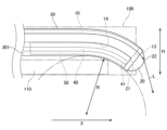
- FIG. 2 is an enlarged side view of the tip side of the optical fiber probe according to the first embodiment of the present invention.
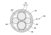
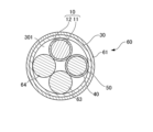
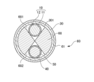
- 3 is a sectional view taken along line III-III in FIG. 2.
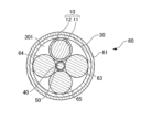
- FIG. 4 is a diagram showing an optical fiber probe according to a second embodiment of the present invention, and is a sectional view corresponding to FIG. 3.
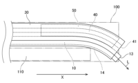
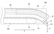
- FIG. It is a side view which shows the optical fiber probe based on 3rd Embodiment of this invention. It is a side view which shows the optical fiber probe based on 4th Embodiment of this invention.
- 4 is a diagram showing an optical fiber probe according to a fifth embodiment of the present invention, and is a sectional view corresponding to FIG. 3.
- FIG. 4 is a diagram showing an optical fiber probe according to a sixth embodiment of the present invention, and is a sectional view corresponding to FIG. 3.
- FIG. 4 is a diagram showing an optical fiber probe according to a seventh embodiment of the present invention, and is a sectional view corresponding to FIG. 3.
- FIG. 4 is a diagram showing an optical fiber probe according to an eighth embodiment of the present invention, and is a sectional view corresponding to FIG. 3.
- FIG. 4 is a diagram showing an optical fiber probe according to a ninth embodiment of the present invention, and is a sectional view corresponding to FIG. 3.
- FIG. 4 is a diagram showing an optical fiber probe according to a tenth embodiment of the present invention, and is a cross-sectional view corresponding to FIG. 3.
- FIG. 3 is a diagram showing an optical fiber probe according to a tenth embodiment of the present invention, and is a cross-sectional view corresponding to FIG. 3.
- FIG. 4 is a diagram showing an optical fiber probe according to an eleventh embodiment of the present invention, and is a sectional view corresponding to FIG. 3.
- FIG. 4 is a diagram showing an optical fiber probe according to a twelfth embodiment of the present invention, and is a cross-sectional view corresponding to FIG. 3.
- FIG. 1 is a side view of the optical fiber probe 1.
- FIG. 2 is an enlarged side view showing the distal end side of the optical fiber probe 1 housed in a protective tube for an endoscope.
- FIG. 3 is a sectional view taken along line III-III shown in FIG. Note that in FIG. 2, illustration of the holding portion 60 is omitted.
- the optical fiber probe 1 of this embodiment is installed in a medical device that performs photoimmunotherapy, which is one of the cancer treatment methods.
- Photoimmunotherapy involves administering to the human body a drug consisting of an antibody that binds to cancer cells and a substance that reacts to light, and then irradiating the drug bound to cancer cells with laser light to destroy the cancer cells. Treat cancer.
- the present invention is not limited to photoimmunotherapy, but can also be used for treatment methods that use laser light, such as photodynamic therapy.
- the optical fiber probe 1 is used, for example, while being inserted into a conduit provided in an endoscope.
- the optical fiber probe 1 of this embodiment is housed in a guide tube 100 for insertion into a channel of an endoscope, with its distal end side bent.
- the guide tube 100 is a tube whose outer diameter H is 3 mm or less. For this reason, it is preferable that the distal end side of the optical fiber probe 1 is bent within a range that can be accommodated in a tube having an outer diameter H of 3 mm or less. Note that the optical fiber probe 1 is accommodated in the guide tube 100 so that the tip portion onto which the laser beam L is irradiated can be exposed to the outside.
- the optical fiber probe 1 includes an optical transmission cable 10, an optical bending section 20, a tubular member 30, a bending holding member 40, a protection member 50, a holding section 60, and a cable protection member 70. and.
- the optical fiber probe 1 emits laser light L generated from a laser oscillator (not shown) as a light source.
- the holding part 60 is arranged at the outermost side, and the light bending part 20, the optical transmission cable 10, and the bending holding member 40 are arranged at the innermost side. For this reason, in FIGS. 1 and 2, portions exposed to the outside are shown with solid lines, and portions covered with other members and not exposed to the outside are shown with broken lines.
- the laser oscillator has a semiconductor laser, and generates laser light L by causing electricity to flow through the semiconductor laser to cause laser oscillation.
- the laser oscillator generates red laser light L having a wavelength of 600 nm or more and 700 nm or less.
- the laser light L generated from the laser oscillator may be a continuous wave or a pulse wave.
- the optical transmission cable 10 is an optical fiber cable having an optical transmission path through which a laser beam L emitted from a laser oscillator is transmitted.
- the optical transmission cable 10 has a laser oscillator disposed on its base end side, transmits laser light L emitted from the laser oscillator via an optical transmission path, and emits it from the distal end portion 13 .
- a light refraction section 20 is connected to the tip end 13 of the optical transmission cable 10. That is, in this embodiment, the optical transmission cable 10 emits the transmitted laser light L toward the light refraction section 20 .
- the optical transmission cable 10 is a plastic fiber and includes a core 11 as an optical transmission path and a cladding 12 formed around the outer periphery of the core 11.
- the optical transmission cable 10 has, for example, an outer diameter of 500 ⁇ m, and an outer diameter of the core 11 of 250 ⁇ m.
- the core 11 preferably has an outer diameter corresponding to a multimode fiber.
- the optical transmission cable 10 of this embodiment is a single-core optical fiber, it may be a multi-core optical fiber. Further, the optical transmission cable 10 may be an optical fiber made of a quartz-based material.
- the optical transmission cable 10 may be a polymer clad optical fiber in which the core 11 is made of a quartz-based material and the cladding 12 is made of a resin such as a hard polymer.
- the hard polymer include fluororesins such as PTFE, PVDF, and ETFE, polyimide, and copolymers thereof.
- the optical transmission cable 10 of this embodiment has a bent portion 14 on the distal end 13 side thereof, which is bent together with the bending holding member 40 so as to be inclined with respect to the extending direction X of the guide tube 100. It is preferable that the bending radius R of the bent portion 14 is 2 cm or less. By setting the bending radius R to 2 cm or less, the optical fiber probe 1 can be accommodated in the guide tube 100 for endoscopes having a general pipe diameter and an outer diameter H of 3 mm or less. As shown in FIG. 2, the optical transmission cable 10 has a fixing jig 110 disposed on the distal end side of the optical fiber probe 1 inside the guide tube 100 so that the bending portion 14 can maintain its bending radius R more reliably.
- the stretching direction X of the guide tube 100 is also the same direction as the stretching direction of the endoscope, the direction in which the endoscope is inserted into the organ of the human body, and the direction in which the optical transmission cable 10 is inserted.
- the light refracting unit 20 refracts and emits the laser beam L emitted from the core 11 at the tip portion 13 of the optical transmission cable 10.
- the light refracting section 20 of this embodiment is formed by a hemispherical microlens. Specifically, the light refraction section 20 is connected to the tip section 13, and has a flat entrance surface 21 into which the laser light L transmitted from the optical transmission cable 10 is incident, and a flat entrance surface 21 from which the incident laser light L is emitted. It has an output surface 22 formed in a curved shape that extends in the output direction.
- the light refracting section 20 refracts the laser beam L incident from the tip end 13 at the output surface 22 and outputs the laser beam L in a direction inclined with respect to the insertion direction of the optical transmission cable 10 .
- the tubular member 30 is a flexible cylindrical tube.
- the tubular member 30 accommodates a portion of the optical transmission cable 10 and a portion of the light refraction section 20 in a cavity 301 inside thereof.
- the optical transmission cable 10 is inserted into the tubular member 30 such that at least the tip end 13 side is located in the cavity 301 of the tubular member 30.
- the optical transmission cable 10 is housed in the cavity 301 of the tubular member 30 while extending in the axial direction of the tubular member 30. As shown in FIGS.
- the light refracting unit 20 is housed in the tubular member 30 such that the entrance surface 21 connected to the tip portion 13 is located within the cavity 301 of the tubular member 30 and the exit surface 22 is exposed to the outside of the tubular member 30.
- the material for the tubular member 30 include polyimide, silicone, polytetrafluoroethylene (PTFE), and the like.
- the bending holding member 40 is an elongated member that can maintain a bent state.
- the bending holding member 40 is arranged along the optical transmission cable 10 at least on the distal end 13 side of the optical transmission cable 10 .
- the material of the bending holding member 40 may be, for example, a metal material such as stainless steel, tungsten, or a shape memory alloy, or a resin material such as acrylic resin.
- the shape of the bending holding member 40 is not particularly limited, and may be, for example, cylindrical, cylindrical, or flat.
- the bending holding member 40 of this embodiment is formed of a stainless steel metal wire. Further, the bending holding member 40 of this embodiment has its tip portion 41 connected to the light refraction portion 20 .
- the bending holding member 40 is bent so that the bending radius of the optical transmission cable 10 is at a desired angle.
- the bending holding member 40 is formed of a metal wire made of a shape memory alloy
- the optical fiber probe 1 when shipped as a product, it is bent at a desired angle and memorized, so that the bent state is maintained at the desired angle. can be maintained for a longer period of time.
- the bending holding member 40 of this embodiment is bent along the bending portion 14 of the optical transmission cable 10. Note that in this embodiment, the bending holding member 40 is arranged inside the bending portion 14 of the optical transmission cable 10.
- the protection member 50 covers the outer peripheral surface of the metal wire of the bending holding member 40.
- the protection member 50 of this embodiment is a flexible cylindrical tube, and the bending holding member 40 is housed inside the protection member 50 to cover the outer circumferential surface of the metal wire. Thereby, the outer peripheral surface of the optical transmission cable 10 can be protected from the metal wires arranged along the optical transmission cable 10.
- the material for the protection member 50 includes, for example, polyimide, silicone, polytetrafluoroethylene (PTFE), and the like.
- the bending holding member 40 and the protection member 50 provided on the outer periphery thereof may be collectively referred to as the bending holding member 40.
- the holding part 60 holds the optical transmission cable 10, the bending holding member 40, and the tubular member 30 so that their relative positions do not change.
- the holding part 60 of this embodiment holds the optical transmission cable 10 so that the relative positions of the optical transmission cable 10, the bending holding member 40, and the tubular member 30 do not change at least in the axial direction of the optical transmission cable 10.
- the holding portion 60 of this embodiment includes a first restraint member 61 and a second restraint member 62 arranged along the outer peripheral surface of the tubular member 30.
- the first restraining member 61 and the second restraining member 62 are, for example, cylindrical heat-shrinkable tubes whose diameter can be reduced by heat.
- the first restraining member 61 and the second restraining member 62 are arranged on the distal end portion 13 side of the optical transmission cable 10 with a space between them.
- examples of the material for the heat-shrinkable tube include FEP (a fluororesin obtained by co-merging tetrafluoroethylene and hexafluoropropylene).
- the first restraining member 61 is a member that restrains the optical transmission cable 10, the bending holding member 40, etc. from moving within the tubular member 30 on the distal end side of the optical fiber probe 1. As shown in FIGS. 1 and 2, the first restraining member 61 is disposed at a position farther from the light refracting section 20 than the second restraining member 62, and is arranged at a position further away from the optical transmission cable 10 in the tubular member 30, the bending holding member 40, and Covers the portion that accommodates the protection member 50. As shown in FIG.
- the optical transmission cable 10 and the bending holding member 40 covered by the protection member 50 are located in the cavity 301 of the tubular member 30, and the first restraining member 61 is located outside the tubular member 30.
- the first restraining member 61 is heat-shrinked, and a force is applied toward the inner diameter of the tubular member 30 .
- the optical transmission cable 10, the protection member 50, the bending holding member 40, and the tubular member 30 are in close contact with each other, and their relative positions are fixed.
- the second restraint member 62 is a member that restrains the optical transmission cable 10, the light refraction unit 20, the bending holding member 40, etc. from moving within the tubular member 30 on the light refraction unit 20 side.
- the second restraint member 62 covers the portion of the tubular member 30 where the light refraction portion 20 and the optical transmission cable 10 are connected and the vicinity thereof, as shown in FIGS. 1 and 2. That is, the first restraining member 61 accommodates the portion of the tubular member 30 that accommodates the light refracting portion 20 and the bending holding member 40 that is disposed near and along the distal end portion 13 of the optical transmission cable 10 in the tubular member 30. Cover part.
- the first restraining member 61 is heat-shrinked, and a force is applied toward the inner diameter of the tubular member 30 .
- the optical transmission cable 10, the protection member 50, the bending holding member 40, and the tubular member 30 are in close contact with each other in the tip portion 13 and its vicinity, and the optical transmission cable 10, the bending holding member 40, etc. are connected to each other.
- the light refracting section 20 and the tubular member 30 are in close contact with each other.
- the relative positions between the optical transmission cable 10, the optical bending section 20, the tubular member 30, the bending holding member 40, and the protection member 50 are fixed.
- the first restraint member 61 and the second restraint member 62 are heat-shrinked when the optical fiber probe 1 is manufactured.
- the cable protection member 70 is a flexible cylindrical tube for protecting the optical transmission cable 10. As shown in FIG. 1, the cable protection member 70 accommodates the proximal end of the optical transmission cable 10 from the portion of the optical transmission cable 10 that is not inserted into the tubular member 30 in its inner cavity. The cable protection member 70 is spaced apart from the cable protection member 70 in the direction in which the optical transmission cable 10 extends. Examples of the material for the cable protection member 70 include nylon, silicone, polytetrafluoroethylene (PTFE), and the like.
- the bending holding member 40 is held at the bending portion 14 so that the optical transmission cable 10 and the bending holding member 40 are held in the tubular member 30 so that their relative positions do not change by the holding portion 60. is bent along.
- the bent state of the bent portion 14 can be more reliably maintained also on the distal end portion 13 side. Therefore, the distal end portion 13 of the optical transmission cable 10 can be maintained in a bent state, and the laser beam L can be irradiated in a direction inclined with respect to the insertion direction of the optical transmission cable 10 into the human body.
- FIG. 4 is a diagram showing the optical fiber probe 1 according to the second embodiment, and is a sectional view corresponding to FIG. 3.
- components corresponding to those of the first embodiment are designated by corresponding reference numerals with the same regularity. The explanation may be omitted or incorporated.
- the optical fiber probe 1 of this embodiment includes an optical transmission cable 10, an optical bending section 20, a tubular member 30, a bending holding member 40, a protection member 50, a holding section 60, and a cable protection member 70. Be prepared.
- the optical fiber probe 1 of this embodiment differs from the optical fiber probe 1 of the first embodiment mainly in the configuration of the holding section 60.
- the holding portion 60 of this embodiment differs from the holding portion 60 of the first embodiment in that it includes intervening members 63 and 64 in addition to a first restraining member 61 and a second restraining member 62.
- the intervening members 63, 64 are flexible, elongated members that are housed in the hollow portion 301 of the tubular member 30.
- the intervening members 63, 64 are arranged inside the tubular member 30 along the bending retention member 40 and the optical transmission cable 10 that are covered with the protective member 50.
- the intervening members 63, 64 fill the space of the hollow portion 301 of the tubular member 30.
- the shape of the intervening members 63, 64 is cylindrical as shown in FIG. 3, but the shape is not particularly limited.
- the shape of the intervening members 63, 64 may be cylindrical or plate-like.
- the optical transmission cable 10 when viewed in the axial direction of the tubular member 30, the optical transmission cable 10 is disposed opposite the bending retention member 40, and the intervening member 63 is disposed opposite the intervening member 64.
- the intervening members 63 and 64 have approximately the same outer diameter, and the outer diameter of the protective member 50 covering the bending retention member 40 and the optical transmission cable 10 are formed to be approximately the same. This makes it possible to more reliably maintain the relative positions of the bending retention member 40 and the optical transmission cable 10 in the hollow portion 301.
- FIG. 5 is a side view showing the optical fiber probe 1 according to the third embodiment.
- structures corresponding to those of the above-described embodiment are given corresponding symbols with the same regularity. The explanation may be omitted or incorporated. Note that in FIG. 5, illustration of the holding portion 60 is omitted.
- the optical fiber probe 1 of this embodiment includes an optical transmission cable 10, a tubular member 30, a bending holding member 40, a protection member 50, a holding part 60, and a cable protection member 70.
- the optical fiber probe 1 of this embodiment differs from the optical fiber probe 1 of the first embodiment mainly in that it does not include the optical refraction section 20 and in the position of the optical transmission cable 10 with respect to the bending section 14.
- the optical fiber probe 1 of this embodiment does not include the light refraction section 20 and directly irradiates the laser light L from the tip 13 of the optical transmission cable 10 to the outside.
- the optical transmission cable 10 extends further than the bending holding member 40 in the light irradiation direction. Further, the bending holding member 40 is arranged outside the bent portion 14 of the optical transmission cable 10 . Thereby, the laser beam L emitted from the tip portion 13 can be irradiated onto the cells to be irradiated without interference from the bending holding member 40.
- FIG. 6 is a side view showing the optical fiber probe 1 according to the fourth embodiment.
- structures corresponding to those of the above embodiment are given corresponding symbols with the same regularity. The explanation may be omitted or incorporated. Note that in FIG. 6, illustration of the holding portion 60 is omitted.
- the optical fiber probe 1 according to the fourth embodiment includes an optical transmission cable 10, a tubular member 30, a bending holding member 40, a protection member 50, a holding part 60, and a cable protection member 70.
- the optical fiber probe 1 of this embodiment differs from the optical fiber probe 1 of the third embodiment mainly in the configuration of the distal end portion 13 of the optical transmission cable 10.
- the tip end 13 of the optical transmission cable 10 of the fourth embodiment is formed with an inclined surface 131 that extends in a direction away from the tubular member 30 as it goes inside the bent portion 14.
- the laser beam L hits this inclined surface 131, the laser beam L is refracted along the slope of the inclined surface 131, and the laser beam L can be emitted further to the side with respect to the insertion direction of the guide tube 100 into the human body. .
- FIG. 7 is a diagram showing the optical fiber probe 1 according to the fifth embodiment, and is a sectional view corresponding to FIG. 3.
- components corresponding to those of the second embodiment will be designated by corresponding reference numerals with the same regularity. The explanation may be omitted or incorporated.
- the optical fiber probe 1 of this embodiment includes an optical transmission cable 10, an optical bending section 20, a tubular member 30, a bending holding member 40, a protection member 50, a holding section 60, and a cable protection member 70. Be prepared.
- the optical fiber probe 1 of this embodiment differs from the second embodiment mainly in the positional relationship of the optical transmission cable 10, the bending holding member 40, and the intervening members 63 and 64 within the tubular member 30.
- the optical transmission cable 10 is disposed at a position facing the intervening member 63, and the bending holding member 40 is disposed at a position facing the intervening member 64. That is, when viewed in the axial direction of the tubular member 30, the optical transmission cable 10 is arranged adjacent to the bending holding member 40 and the intervening member 64 in the circumferential direction of the tubular member 30, and the bending holding member 40 is adjacent to the optical transmission cable 10. It is arranged so as to be adjacent to the intervening member 63 in the circumferential direction of the tubular member 30 . Thereby, the relative positions of the bending holding member 40 and the optical transmission cable 10 in the cavity 301 can be maintained more reliably.
- the outer diameters of the intervening members 63 and 64, the outer diameter of the protective member 50 that covers the bending holding member 40, and the outer diameter of the optical transmission cable 10 are approximately equal.
- FIG. 8 is a diagram showing the optical fiber probe 1 according to the sixth embodiment, and is a sectional view corresponding to FIG. 3.
- components corresponding to those of the second embodiment are designated by corresponding reference numerals with the same regularity. The explanation may be omitted or incorporated.
- the optical fiber probe 1 of this embodiment includes an optical transmission cable 10, an optical bending section 20, a tubular member 30, a bending holding member 40, a protection member 50, a holding section 60, and a cable protection member 70. Be prepared.
- the optical fiber probe 1 of this embodiment has the configuration of the holding part 60, the size of the bending holding member 40, and the positional relationship of the optical transmission cable 10, the bending holding member 40, and the intervening members 63, 64, and 65 in the tubular member 30. This is mainly different from the second embodiment.
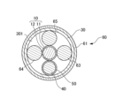
- the holding section 60 of this embodiment differs from the holding section 60 of the second embodiment in that it includes an intervening member 65 in addition to the first restraining member 61, the second restraining member 62, and intervening members 63 and 64.
- the intervening member 65 has the same configuration as the intervening members 63 and 64, and the explanation thereof will be omitted.
- the outer diameter of the bending retention member 40 and the protective member 50 that covers it is smaller than the outer diameter of the optical transmission cable 10 and the intervening members 63, 64, and 65.
- the outer diameter of the intervening members 63, 64, and 65 is also formed to be approximately equal to the outer diameter of the optical transmission cable 10.
- the bending holding member 40 covered with the protective member 50 is arranged approximately at the center of the tubular member 30.
- the optical transmission cable 10 and the intervening members 63 to 65 are arranged so as to surround the bending holding member 40. Specifically, the optical transmission cable 10 is arranged to face the intervening member 65 with the bending holding member 40 in between, and the intervening member 63 is arranged so as to face the intervening member 64 with the bending holding member 40 in between. .
- the optical transmission cable 10 when viewed in the axial direction of the tubular member 30, the optical transmission cable 10 is disposed adjacent to the intervening members 63 and 64 in the circumferential direction of the tubular member 30, and the intervening member 65 is disposed adjacent to the intervening members 63 and 64 of the tubular member 30. They are arranged adjacent to each other in the circumferential direction.
- the protection member 50 that covers the bending holding member 40 is arranged so that its outer peripheral surface is in contact with the outer peripheral surfaces of the optical transmission cable 10 and the intervening members 63 to 65, respectively.
- the outer peripheral surface of the optical transmission cable 10 and the intervening members 63 to 65 are in contact with the inner peripheral surface of the tubular member 30.
- the bending holding member 40 is located approximately at the center of the tubular member 30 when viewed in the axial direction of the tubular member 30, and the relative position with respect to the tubular member 30 and the like is maintained. A force for holding the tip end side of the fiber probe 1 in a bent state can be applied more uniformly.
- FIG. 9 is a diagram showing the optical fiber probe 1 according to the seventh embodiment, and is a sectional view corresponding to FIG. 3.
- components corresponding to those of the sixth embodiment are designated by corresponding reference numerals with the same regularity. The explanation may be omitted or incorporated.
- the optical fiber probe 1 of this embodiment includes an optical transmission cable 10, an optical bending section 20, a tubular member 30, a bending holding member 40, a protection member 50, a holding section 60, and a cable protection member 70. Be prepared.
- the optical fiber probe 1 of this embodiment differs from the sixth embodiment mainly in the sizes of the optical transmission cable 10, the bending holding member 40, and the intervening members 63, 64, and 65, and the positional relationship within the tubular member 30.
- the outer diameters of the intervening members 63 to 65, the outer diameter of the protective member 50 covering the bending holding member 40, and the outer diameter of the optical transmission cable 10 are approximately equal.
- the optical transmission cable 10 is arranged approximately at the center of the tubular member 30 when viewed in the axial direction of the tubular member 30.
- the bending holding member 40 covered with the protection member 50 and the intervening members 63 to 65 are arranged so as to surround the optical transmission cable 10.
- the bending holding member 40 is arranged to face the intervening member 65 with the optical transmission cable 10 in between
- the intervening member 63 is arranged to face the intervening member 64 with the optical transmission cable 10 in between. .
- the bending holding member 40 is disposed adjacent to the intervening members 63 and 64 in the circumferential direction of the tubular member 30, and the intervening member 65 is disposed adjacent to the intervening members 63 and 64 of the tubular member 30. They are arranged adjacent to each other in the circumferential direction.
- the optical transmission cable 10 is arranged so that its outer peripheral surface is in contact with the outer peripheral surfaces of the protective member 50 that covers the bending holding member 40 and the intervening members 63 to 65, respectively.
- the outer peripheral surfaces of the protective member 50 covering the bending holding member 40 and the intervening members 63 to 65 are in contact with the inner peripheral surface of the tubular member 30.
- FIG. 10 is a diagram showing the optical fiber probe 1 according to the eighth embodiment, and is a sectional view corresponding to FIG. 3.
- components corresponding to those of the seventh embodiment are designated by corresponding reference numerals with the same regularity. The explanation may be omitted or incorporated.
- the optical fiber probe 1 of this embodiment includes an optical transmission cable 10, an optical bending section 20, a tubular member 30, a bending holding member 40, a protection member 50, a holding section 60, and a cable protection member 70. Be prepared.
- the sizes and positional relationships within the tubular member 30 of the bending holding member 40, the optical transmission cable 10, the bending holding member 40, and the intervening members 63 to 65 are the same as in the seventh embodiment. , differs from the seventh embodiment in that the holding section 60 includes a regulating member 66.
- the regulating member 66 is formed to fill the gap between the optical transmission cable 10 in the cavity 301, the bending holding member 40 covered by the protective member 50, and the intervening members 63 to 65.
- the regulating member 66 is a member that regulates the movement of the optical transmission cable 10, the bending holding member 40 covered by the protective member 50, and the intervening members 63 to 65.
- the regulating member 66 of this embodiment is an adhesive that is filled and solidified in the gap between the protective member 50 that covers the optical transmission cable 10 and the bending holding member 40 in the cavity 301 and the intervening members 63 to 65.
- the gaps between the optical transmission cable 10, the bending holding member 40, and the intervening members 63 to 65 in the tubular member 30 are filled with the adhesive.
- the first restraining member 61 applies a force toward the inner diameter of the tubular member 30, so that the relative positions of the bending holding member 40 and the optical transmission cable 10 can be held more reliably, and the optical transmission cable 10
- the bent state of the tip portion 13 side can be more firmly maintained.
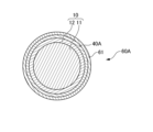
- FIG. 11 is a cross-sectional view showing the optical fiber probe 1 according to the ninth embodiment, corresponding to Fig. 3.
- components corresponding to those in the first embodiment are given the same reference numerals according to the same rule. The description may be omitted or may be cited.
- the optical fiber probe 1 of this embodiment includes an optical transmission cable 10, an optical bending section 20, a tubular member 30, a bending holding member 40, a protection member 50, a holding section 60, and a cable protection member 70. Be prepared.
- the optical fiber probe 1 of this embodiment differs from the optical fiber probe 1 of the first embodiment mainly in the configuration of the holding part 60.
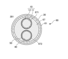
- the holding part 60 of this embodiment differs from the holding part 60 of the first embodiment in that it includes an intervening member 67 in addition to the first restraining member 61 and the second restraining member 62.
- the intervening member 67 is a flexible and elongated member, and is accommodated in the cavity 301 of the tubular member 30.
- the intervening member 67 has a cylindrical shape and is arranged along the tubular member 30 such that its outer circumferential surface is in contact with the inner circumferential surface of the tubular member 30. As shown in FIG. 11, the intervening member 67 has a through hole 671 and a through hole 672 that extend in the axial direction.
- the through holes 671 and 672 are formed at positions facing each other when viewed in the axial direction of the tubular member 30, as shown in FIG.
- the optical transmission cable 10 is inserted into the through hole 671, and the bending holding member 40 covered with the protection member 50 is inserted into the through hole 672.
- the outer peripheral surface of the optical transmission cable 10 contacts the inner peripheral surface of the through hole 671.
- the outer circumferential surface of the protective member 50 that covers the bending holding member 40 contacts the inner circumferential surface of the through hole 672 .
- FIG. 12 is a diagram showing the optical fiber probe 1 according to the tenth embodiment, and is a sectional view corresponding to FIG. 3.
- components corresponding to those of the first embodiment are designated by corresponding reference numerals with the same regularity. The explanation may be omitted or incorporated.
- the optical fiber probe 1 of this embodiment includes an optical transmission cable 10, an optical bending section 20, a tubular member 30, a bending holding member 40, a protection member 50, a holding section 60, and a cable protection member 70. Be prepared.
- the optical fiber probe 1 of this embodiment differs from the optical fiber probe 1 of the first embodiment mainly in the configuration of the holding section 60.
- the holding portion 60 of this embodiment differs from the holding portion 60 of the first embodiment in that it includes an intervening member 68 in addition to a first restraining member 61 and a second restraining member 62.
- the intervening member 68 is a flexible and elongated member, and is accommodated in the cavity 301 of the tubular member 30.
- the intervening member 68 has a cylindrical shape as a whole, and is arranged along the tubular member 30 so that its outer circumferential surface is in contact with the inner circumferential surface of the tubular member 30. As shown in FIG. 12, the intervening member 68 has a groove 681 and a groove 682 that extend in the axial direction.
- the grooves 681 and 682 are formed at positions facing each other when viewed in the axial direction of the tubular member 30, as shown in FIG.
- the optical transmission cable 10 is arranged in the groove 681, and the bending holding member 40 covered with the protection member 50 is arranged in the groove 682.
- the outer peripheral surface of the optical transmission cable 10 contacts the inner surface of the groove 681 and the inner peripheral surface of the tubular member 30 .
- the outer peripheral surface of the protective member 50 that covers the bending holding member 40 contacts the inner surface of the groove 682 and the inner peripheral surface of the tubular member 30 .
- FIG. 13 is a diagram showing the optical fiber probe 1 according to the eleventh embodiment, and is a sectional view corresponding to FIG. 3.
- components corresponding to those of the first embodiment are designated by corresponding reference numerals with the same regularity. The explanation may be omitted or incorporated.
- the optical fiber probe 1 of this embodiment includes an optical transmission cable 10, an optical refraction section 20, a tubular bending holding member 40A, a second holding section 60A, and a cable protection member 70.
- the optical fiber probe 1 of this embodiment has the following points: it includes a tubular bending holding member 40A and a second holding part 60A instead of the bending holding member 40 and the holding part 60, and it does not include the tubular member 30 and the protection member 50. This embodiment differs mainly from the first embodiment.
- the tubular bending retention member 40A is a long, thin tubular member that can maintain a bent state, and differs from the bending retention member 40 of the first embodiment mainly in its shape and arrangement.
- the tubular bending retention member 40A of this embodiment is formed from a stainless steel metal tube.
- the tubular bending holding member 40A accommodates the optical transmission cable 10 and is arranged along the optical transmission cable 10 at least on the distal end side of the optical transmission cable 10. That is, at least the distal end side of the optical transmission cable 10 is inserted into the tubular bending holding member 40A. In this embodiment, at least the distal end side of the optical transmission cable 10 is arranged such that its entire outer circumferential surface is in contact with the inner circumferential surface of the tubular bend holding member 40A. With this configuration, the optical transmission cable 10 inserted into the tubular bending holding member 40A is held with its bending shape changing along the shape of the tubular bending holding member 40A. The tubular bending holding member 40A is bent, for example, by the method described above in the first embodiment so that the bending radius of the optical transmission cable 10 becomes a desired angle.
- the second holding portion 60A holds the optical transmission cable 10 so that the relative position between the optical transmission cable 10 and the tubular bending holding member 40A does not change at least in the axial direction.
- the second holding part 60A of this embodiment has a first restraining member 61 and a second restraining member 62, and the first restraining member 61 is arranged not on the tubular member 30 but along the outer peripheral surface of the tubular bending holding member 40A. This is different from the holding part 60 of the first embodiment in that the holding part 60 is different from the holding part 60 of the first embodiment.
- the optical transmission cable 10 is housed within the tubular bending holding member 40A, and the first restraining member 61 is located outside the tubular bending holding member 40A.
- the first restraining member 61 is thermally contracted, and a force is applied in the inner diameter direction of the tubular bending holding member 40A.
- the optical transmission cable 10 and the tubular bending holding member 40A come into closer contact with each other, and their relative positions are fixed. Thereby, it is possible to bend the tip end 13 side of the optical transmission cable 10 and maintain the bent state.
- FIG. 14 is a diagram showing the optical fiber probe 1 according to the twelfth embodiment, and is a sectional view corresponding to FIG. 3.
- components corresponding to those of the eleventh embodiment are designated by corresponding reference numerals with the same regularity. The explanation may be omitted or incorporated.
- the optical fiber probe 1 of this embodiment includes an optical transmission cable 10, an optical refraction section 20, a tubular bending holding member 40A, a second holding section 60A, and a cable protection member 70.
- the optical fiber probe 1 of this embodiment differs from the eleventh embodiment mainly in the size of the optical transmission cable 10, the configuration of the second holding part 60A, and the like.
- the outer diameter of the optical transmission cable 10 is smaller than the inner diameter of the tubular bend holding member 40A. That is, as shown in FIG. 14, only a part of the outer circumferential surface of the optical transmission cable 10 contacts the inner circumferential surface of the tubular bending holding member 40A when viewed in the axial direction of the tubular bending holding member 40A.
- the second holding part 60A of the present embodiment differs from the second holding part 60A of the eleventh embodiment in that it includes intervening members 63, 64, and 65 in addition to the first restraining member 61 and the second restraining member 62. .
- the intervening members 63 to 65 are flexible, elongated members, and are housed in the cavity 401 of the tubular bending holding member 40A.
- the intervening members 63 to 65 are arranged along the optical transmission cable 10 within the tubular bend holding member 40A. Further, in this embodiment, the outer diameters of the intervening members 63 to 65 are formed to be approximately equal.
- the optical transmission cable 10 is placed at a position facing the intervening member 65, and the intervening member 63 is placed at a position facing the intervening member 64 when viewed in the axial direction of the tubular bending holding member 40A. That is, when viewed in the axial direction of the tubular bend holding member 40A, the optical transmission cable 10 is arranged adjacent to the intervening members 63 and 64 in the circumferential direction of the tubular bend holding member 40A, and the intervening member 65 is adjacent to the intervening members 63 and 64. They are arranged adjacent to each other in the circumferential direction of the tubular bending holding member 40A.
- the outer peripheral surfaces of the optical transmission cable 10 and the intervening members 63 to 65 are in contact with the inner peripheral surface of the tubular bend holding member 40A. Further, the outer circumferential surface of the optical transmission cable 10 is in contact with the inner circumferential surface of the tubular bend holding member 40A and the outer circumferential surfaces of the intervening members 63 and 64.
- the first restraining member 61 is thermally contracted, and a force is applied in the inner diameter direction of the tubular bending holding member 40A.
- the optical transmission cable 10 and the tubular bending holding member 40A come into closer contact with each other, and their relative positions are fixed. Thereby, the relative position of the tubular bending holding member 40A and the optical transmission cable 10 can be reliably maintained while the optical transmission cable 10 is set to a size that allows easy insertion into the tubular bending holding member 40A.
- the medical optical fiber probe 1 includes at least an optical transmission cable 10 that transmits a laser beam L emitted from a light source and emits the transmitted laser beam L from a tip 13; On the distal end portion 13 side, an elongated bending holding member 40 that is arranged along the optical transmission cable 10 and capable of maintaining the bent state, a tubular member 30 into which the optical transmission cable 10 and the bending holding member 40 are inserted, and an optical transmission A holding part 60 is provided to hold the cable 10, the bending holding member 40, and the tubular member 30 so that their relative positions do not change.
- the bending retention member 40 is arranged along the optical transmission cable 10 on the tip 13 side of the optical transmission cable 10 inside the tubular member 30, and their relative positions are fixed, so that the tip 13 side of the optical transmission cable 10 can be bent and maintained in a bent state. Therefore, while suppressing heat generation during irradiation, laser light L with little beam cracking and high beam quality can be irradiated in a direction inclined to the insertion direction of the optical transmission cable 10. The beam can be expanded over a short distance.
- an oblique emission diffuser can be manufactured by the simple method of arranging the bending retention member 40 along the optical transmission cable 10 inside the tubular member 30 without performing special processing such as prism processing.
- the holding portion 60 holds the optical transmission cable 10, the bending holding member 40, and the tubular member 30 so that the relative positions do not change, at least in the axial direction of the optical transmission cable 10.
- the relative positions of the bending holding member 40 and the tubular member 30 with respect to the optical transmission cable 10 in the axial direction of the optical transmission cable 10 can be prevented from shifting, so that, for example, the light emitted from the tip 13 of the optical transmission cable 10 is It is possible to prevent interference from the holding member 40 and the tubular member 30.
- the bending holding member 40 is formed of a metal wire.
- the bent state of the optical transmission cable 10 can be maintained more easily and reliably.
- the optical fiber probe 1 includes a protection member 50 that covers the outer peripheral surface of the metal wire.
- the outer surface of the metal wire is covered by the protective member 50, so that the metal wire arranged along the optical transmission cable 10 does not come into direct contact with the outer surface of the optical transmission cable 10, thereby protecting the optical transmission cable 10.
- the holding section 60 is arranged along the outer circumferential surface of the tubular member 30 and fixes the relative positions of the optical transmission cable 10, the bending holding member 40, and the tubular member 30. It has a first restraint member 61 and a second restraint member 62.
- the holding section 60 includes intervening members 63 and 64 arranged along the optical transmission cable 10 and the bending holding member 40.
- the holding part 60 is formed to fill the gap between the optical transmission cable 10, the bending holding member 40, and the intervening members 63 to 65 in the tubular member 30, and 10, a bending holding member 40, and a regulating member 66 that regulates the movement of the intervening members 63 to 65.
- the gaps between the optical transmission cable 10, the bending holding member 40, and the intervening members 63 to 65 in the tubular member 30 are filled with the regulating member 66, so that the bending holding member 40 and the optical transmission cable 10 are The position can be held more reliably, and the bent state of the tip end 13 side of the optical transmission cable 10 can be more firmly maintained.
- the optical fiber probe 1 is provided on the distal end 13 side of the optical transmission cable 10 and directs the laser beam L emitted from the distal end 13 of the optical transmission cable 10 in the axial direction of the optical transmission cable 10.
- the holding section 60 includes the optical transmission cable 10, the bending holding member 40, and the tubular member 30 for the optical refraction section 20 at least in the axial direction of the optical transmission cable 10. Keep their relative positions unchanged.
- the optical transmission cable 10 has a bent portion 14 bent together with the bending holding member 40 on the distal end portion 13 side thereof, and the optical transmission cable 10, the bending holding member 40, and
- the tubular member 30 is housed in a guide tube 100 having an outer diameter of 3 mm or less and inserted into a channel of an endoscope.
- the bend 14 is already provided and is housed in the guide tube 100 for an endoscope having a typical duct diameter, making it highly versatile.
- the bending portion 14 has a bending radius R of 2 cm or less.
- the optical fiber probe 1 can be accommodated in the guide tube 100 for an endoscope having a diameter of a general conduit.
- the optical transmission cable 10 extends further than the bending holding member 40 in the light emission direction.
- the laser beam L can be irradiated onto cancer cells and the like to be irradiated without interference from the bending holding member 40.
- the medical optical fiber probe 1 includes an optical transmission cable 10 that transmits the laser beam L emitted from a light source and emits the transmitted light from the tip 13, and at least the tip of the optical transmission cable 10.
- an elongated tubular bending holding member 40A that accommodates the optical transmission cable 10 and is arranged along the optical transmission cable 10 and can maintain a bent state, and an optical transmission cable at least in the axial direction of the optical transmission cable 10. 10 and the tubular bending holding member 40A, the second holding part 60A holds the tubular bending holding member 40A so that the relative position thereof does not change.
- the optical transmission cable 10 is accommodated in the tubular bending holding member 40A that can maintain the bent state, and since their relative positions are fixed, the distal end 13 side of the optical transmission cable 10 is bent. It is also possible to maintain the bent state. Therefore, while suppressing heat generation during irradiation, the laser beam L can be irradiated with less beam cracking and high beam quality in a direction inclined with respect to the insertion direction of the optical transmission cable 10. The beam can be spread over a short distance. Further, the oblique emission diffuser can be manufactured by a simple method of accommodating the optical transmission cable 10 within the tubular bending holding member 40A without performing any special processing such as prism processing.
- the holding part 60 had two intervening members 63 and 64, but the number of intervening members is not particularly limited.
- the number of intervening members of the holding part 60 may be one, or three or more.
- the first restraint member 61 and the second restraint member 62 are arranged separately along the optical transmission cable 10 at intervals, but the first restraint member 61 and the second restraint member 62 may be integrated.
- the holding part 60 had two intervening members 63 and 64, but the number of intervening members is not particularly limited.
- the number of intervening members of the holding part 60 may be one, or three or more.
- the cavity 301 may be formed to be filled with the regulating member 66. Further, in the twelfth embodiment, the cavity 401 may be filled with the regulating member 66.
- the optical fiber probe 1 may be configured without the protection member 50. That is, a configuration may be adopted in which the outer circumferential surface of the bending holding member 40 is not covered with the protection member 50.
- the optical fiber probe 1 was equipped with the second holding section 60A, but may be configured without the second holding section 60A.
- the optical fiber probe 1 is formed between the tubular bending holding member 40A and the optical transmission cable 10 in the radial direction, and the tubular protection member covers the inner peripheral surface of the tubular bending holding member 40A. 50 may be used.
- optical fiber probe 1 is used as a disposable product in the medical field for hygiene reasons, it is possible to ensure a sustainable consumption and production pattern by collecting the product and reusing lenses, etc. can contribute to
Landscapes
- Health & Medical Sciences (AREA)
- Biomedical Technology (AREA)
- Engineering & Computer Science (AREA)
- Life Sciences & Earth Sciences (AREA)
- Nuclear Medicine, Radiotherapy & Molecular Imaging (AREA)
- Pathology (AREA)
- Radiology & Medical Imaging (AREA)
- Animal Behavior & Ethology (AREA)
- General Health & Medical Sciences (AREA)
- Public Health (AREA)
- Veterinary Medicine (AREA)
- Biophysics (AREA)
- Radiation-Therapy Devices (AREA)
- Endoscopes (AREA)
Priority Applications (3)
| Application Number | Priority Date | Filing Date | Title |
|---|---|---|---|
| JP2024548174A JPWO2024062901A1 (cg-RX-API-DMAC7.html) | 2022-09-21 | 2023-08-31 | |
| CN202380067986.1A CN119907701A (zh) | 2022-09-21 | 2023-08-31 | 光纤探头 |
| DE112023003925.9T DE112023003925T5 (de) | 2022-09-21 | 2023-08-31 | Optische fasersonde |
Applications Claiming Priority (2)
| Application Number | Priority Date | Filing Date | Title |
|---|---|---|---|
| JP2022150453 | 2022-09-21 | ||
| JP2022-150453 | 2022-09-21 |
Publications (1)
| Publication Number | Publication Date |
|---|---|
| WO2024062901A1 true WO2024062901A1 (ja) | 2024-03-28 |
Family
ID=90454211
Family Applications (1)
| Application Number | Title | Priority Date | Filing Date |
|---|---|---|---|
| PCT/JP2023/031949 Ceased WO2024062901A1 (ja) | 2022-09-21 | 2023-08-31 | 光ファイバプローブ |
Country Status (4)
| Country | Link |
|---|---|
| JP (1) | JPWO2024062901A1 (cg-RX-API-DMAC7.html) |
| CN (1) | CN119907701A (cg-RX-API-DMAC7.html) |
| DE (1) | DE112023003925T5 (cg-RX-API-DMAC7.html) |
| WO (1) | WO2024062901A1 (cg-RX-API-DMAC7.html) |
Citations (2)
| Publication number | Priority date | Publication date | Assignee | Title |
|---|---|---|---|---|
| JP2015024030A (ja) * | 2013-07-26 | 2015-02-05 | 株式会社アライ・メッドフォトン研究所 | 医療用具及び医療用具用の光放射プローブ取付キット |
| JP2021065256A (ja) * | 2019-10-17 | 2021-04-30 | 朝日インテック株式会社 | 光照射デバイス、及び、光照射システム |
-
2023
- 2023-08-31 JP JP2024548174A patent/JPWO2024062901A1/ja active Pending
- 2023-08-31 DE DE112023003925.9T patent/DE112023003925T5/de active Pending
- 2023-08-31 WO PCT/JP2023/031949 patent/WO2024062901A1/ja not_active Ceased
- 2023-08-31 CN CN202380067986.1A patent/CN119907701A/zh active Pending
Patent Citations (2)
| Publication number | Priority date | Publication date | Assignee | Title |
|---|---|---|---|---|
| JP2015024030A (ja) * | 2013-07-26 | 2015-02-05 | 株式会社アライ・メッドフォトン研究所 | 医療用具及び医療用具用の光放射プローブ取付キット |
| JP2021065256A (ja) * | 2019-10-17 | 2021-04-30 | 朝日インテック株式会社 | 光照射デバイス、及び、光照射システム |
Also Published As
| Publication number | Publication date |
|---|---|
| JPWO2024062901A1 (cg-RX-API-DMAC7.html) | 2024-03-28 |
| DE112023003925T5 (de) | 2025-07-03 |
| CN119907701A (zh) | 2025-04-29 |
Similar Documents
| Publication | Publication Date | Title |
|---|---|---|
| JP7454571B2 (ja) | 光治療診断装置 | |
| JP7336119B1 (ja) | 光照射デバイスおよび光照射システム | |
| JPS63212343A (ja) | カテーテル | |
| WO2020071023A1 (ja) | 光照射医療装置 | |
| US20160089203A1 (en) | Irradiation device | |
| JP7308123B2 (ja) | 光照射デバイス、及び、光照射システム | |
| JP2021090503A (ja) | 光照射デバイス | |
| US12239416B2 (en) | Light therapy diagnostic device and method for operating the same | |
| KR101808675B1 (ko) | 카테터 모듈 및 이를 포함하는 카테터 시스템 | |
| US20260083978A1 (en) | Light radiating fiber probe | |
| JP6498028B2 (ja) | 内視鏡用光線力学的治療装置 | |
| CN119907701A (zh) | 光纤探头 | |
| WO2023281918A1 (ja) | 光照射医療装置 | |
| CN116157181A (zh) | 光照射设备以及光照射系统 | |
| US20250264652A1 (en) | Optical diffusion device | |
| CN116568359B (zh) | 光照射医疗装置 | |
| WO2023047711A1 (ja) | 光照射医療装置 | |
| JP7774429B2 (ja) | 光拡散装置およびこれを用いた医療機器 | |
| WO2018008622A1 (ja) | 光照射プローブ及びその製造方法 | |
| JP5681964B1 (ja) | エネルギー装置のための光制御ユニット及びエネルギー照射装置 | |
| CN120091801A (zh) | 光扩散装置 | |
| JP7718934B2 (ja) | 光照射医療装置 | |
| WO2023281917A1 (ja) | 光照射医療装置 | |
| JP2023009439A (ja) | 光照射医療装置 | |
| JP2023009440A (ja) | 光照射医療装置 |
Legal Events
| Date | Code | Title | Description |
|---|---|---|---|
| 121 | Ep: the epo has been informed by wipo that ep was designated in this application |
Ref document number: 23868025 Country of ref document: EP Kind code of ref document: A1 |
|
| WWE | Wipo information: entry into national phase |
Ref document number: 2024548174 Country of ref document: JP |
|
| WWE | Wipo information: entry into national phase |
Ref document number: 202380067986.1 Country of ref document: CN |
|
| WWE | Wipo information: entry into national phase |
Ref document number: 112023003925 Country of ref document: DE |
|
| WWP | Wipo information: published in national office |
Ref document number: 202380067986.1 Country of ref document: CN |
|
| WWP | Wipo information: published in national office |
Ref document number: 112023003925 Country of ref document: DE |
|
| 122 | Ep: pct application non-entry in european phase |
Ref document number: 23868025 Country of ref document: EP Kind code of ref document: A1 |