WO2024057378A1 - 光給電方法及び光給電システム - Google Patents
光給電方法及び光給電システム Download PDFInfo
- Publication number
- WO2024057378A1 WO2024057378A1 PCT/JP2022/034144 JP2022034144W WO2024057378A1 WO 2024057378 A1 WO2024057378 A1 WO 2024057378A1 JP 2022034144 W JP2022034144 W JP 2022034144W WO 2024057378 A1 WO2024057378 A1 WO 2024057378A1
- Authority
- WO
- WIPO (PCT)
- Prior art keywords
- optical power
- power supply
- amplifier
- optical
- light source
- Prior art date
- Legal status (The legal status is an assumption and is not a legal conclusion. Google has not performed a legal analysis and makes no representation as to the accuracy of the status listed.)
- Ceased
Links
Images









Classifications
-
- H—ELECTRICITY
- H04—ELECTRIC COMMUNICATION TECHNIQUE
- H04B—TRANSMISSION
- H04B10/00—Transmission systems employing electromagnetic waves other than radio-waves, e.g. infrared, visible or ultraviolet light, or employing corpuscular radiation, e.g. quantum communication
- H04B10/80—Optical aspects relating to the use of optical transmission for specific applications, not provided for in groups H04B10/03 - H04B10/70, e.g. optical power feeding or optical transmission through water
- H04B10/806—Arrangements for feeding power
- H04B10/807—Optical power feeding, i.e. transmitting power using an optical signal
-
- H—ELECTRICITY
- H04—ELECTRIC COMMUNICATION TECHNIQUE
- H04B—TRANSMISSION
- H04B10/00—Transmission systems employing electromagnetic waves other than radio-waves, e.g. infrared, visible or ultraviolet light, or employing corpuscular radiation, e.g. quantum communication
- H04B10/80—Optical aspects relating to the use of optical transmission for specific applications, not provided for in groups H04B10/03 - H04B10/70, e.g. optical power feeding or optical transmission through water
Definitions
- the present invention relates to an optical power supply method and an optical power supply system.
- the device at the light receiving end here is, for example, an electronic device such as an IoT device installed in a deep forest, underground, or inside a clay pipe or manhole. It is assumed that the surrounding environment of such a device is, for example, difficult to harvest energy using sunlight or the like, or is outside the communication area of a mobile phone. Furthermore, it is assumed that the installation location of the device is far from the light source for optical power supply.
- FIG. 15 is a diagram showing an example of the configuration of an optical power supply system using a conventional optical power supply method.
- an optical power supply line installed in a power supply target area which is a non-electrified area, for example, is connected to an optical power supply line using an optical fiber from a light source installed in a station building, etc.
- Light is transmitted to.
- As the network configuration of the optical power supply line for example, an SS (Single Star) configuration without branching is used in order to reduce branching loss.
- SS Single Star
- the network configuration of the optical power supply line for example, an SS (Single Star) configuration without branching is used in order to reduce branching loss.
- a PD Photodiode
- the received light is converted into an electrical signal, and power is supplied to the power supply target devices within the power supply target area.
- FIG. 16 is a schematic diagram showing the amount of power supplied by an optical power supply system using a conventional optical power supply method.
- the conventional optical power supply method the longer the distance between the light source and the optical power supply unit, the greater the optical fiber loss that occurs in the optical power supply line, so the amount of power supplied becomes smaller. It ends up. Therefore, in the conventional optical power supply method, if the distance between the light source and the optical power supply unit is long, it may not be possible to supply sufficient power to operate the equipment in the power supply target area.
- One way to deal with this is to increase the amount of power supplied by increasing the amount of light from the light source, but in that case, there is a problem that the optical fiber may overheat due to the fiber fuse phenomenon, which may impair safety. there were.
- the present invention has been made in view of the above technical background, and aims to provide a technology that can increase the amount of power supplied without compromising safety in optical power supply.
- One aspect of the present invention includes a step in which a light source transmits light for optical power supply to an optical power supply line connected to an optical power supply unit, and an amplifier installed in the middle of a path of the optical power supply line transmits light from the light source.
- the optical power supply method includes the steps of: amplifying the light amplified by the amplifier; and a step of the optical power supply unit receiving the light amplified by the amplifier and photoelectrically converting the light to obtain electric power.
- one aspect of the present invention provides a light source that transmits light for optical power supply to an optical power supply line connected to an optical power supply unit, and a light source that is installed in the middle of a route of the optical power supply line and that transmits the light transmitted from the light source.
- the optical power supply system includes an amplifier that amplifies the light, and the optical power supply section that receives the light amplified by the amplifier and photoelectrically converts the light to obtain electric power.
- the present invention makes it possible to increase the amount of power supplied without compromising safety in optical power supply.
- FIG. 1 is an overall configuration diagram of an optical power feeding system 1 according to a first embodiment of the present invention.
- FIG. 2 is a schematic diagram showing the amount of energy in the optical fiber according to the optical power feeding system 1 according to the first embodiment of the present invention.
- FIG. 2 is an overall configuration diagram of an optical power feeding system 1a according to a second embodiment of the present invention.
- FIG. 2 is an overall configuration diagram of an optical power feeding system 1b according to a third embodiment of the present invention. It is a flow chart which shows operation of switch control part 42 of optical power feeding system 1b in a 3rd embodiment of the present invention. It is an overall block diagram of the optical power feeding system 1c in the 4th Embodiment of this invention.
- FIG. 1 is a diagram illustrating an example of introducing an optical power supply system in an embodiment of the present invention.
- 1 is a diagram showing an example of the configuration of an optical power supply system using a conventional optical power supply method.
- FIG. 2 is a schematic diagram showing the amount of power supplied by an optical power supply system using a conventional optical power supply method.
- FIG. 1 is an overall configuration diagram of an optical power feeding system 1 according to a first embodiment of the present invention.
- the optical power feeding system 1 is a system for supplying power by optical power feeding to devices existing in a power feeding target area (hereinafter referred to as "power feeding target devices").
- the power supply target area in this embodiment is, for example, a non-electrified area.
- the power supply target device is, for example, an electronic device such as an IoT device installed in a deep forest, underground, or inside a clay pipe or manhole. It is assumed that the surrounding environment of such a device is, for example, difficult to harvest energy using sunlight or the like, or is outside the communication area of a mobile phone. Furthermore, it is assumed that the installation location of the device is far from the light source for optical power supply. As shown in FIG. 1, the optical power supply system 1 includes a light source 11, an optical power supply section 20, an amplifier 31, an energy harvester 32, and an optical power supply line 51.
- the light source 11 is installed, for example, in a building such as a communication base station building. This station building is located in an electrified area, for example, far away from the power supply target area.
- the light source 11 emits light for optical power supply and sends it to the optical power supply line 51.
- As the light for optical power supply for example, constantly lit light may be used.
- the light sent out by the light source 11 is transmitted to the optical power supply section 20 via the optical power supply line 51.
- the optical power supply line 51 is configured using an optical fiber.
- As the network configuration of the optical power supply line 51 for example, an SS (Single Star) configuration without branching is used for the purpose of reducing branching loss.
- the optical power supply unit 20 is installed, for example, inside or near the power supply target area.
- the optical power supply section 20 includes, for example, a PD (Photodiode) not shown.
- the light sent out by the light source 11 is received by the PD of the optical power supply section 20 .
- the optical power supply unit 20 converts the received light into an electrical signal and supplies power to the device to be powered.
- the amplifier 31 is an optical amplifier that replenishes (amplifies) energy lost due to optical fiber loss during optical transmission on the optical power supply line 51.
- the amplifier 31 is located, for example, in a non-electrified area, and is driven by electric power generated by the energy generator 32.
- Non-Patent Document 2 devices using various energy harvesting techniques described in Non-Patent Document 2 can be used.
- Various energy harvesting techniques are, for example, techniques for obtaining electric power using photovoltaic power generation (solar cells), piezoelectric effect, or electromagnetic induction.
- harvesting technology is a technology that harvests dilute energy that exists in various forms in the surrounding environment, such as light, vibration, heat, and radio waves, and converts it into electricity.
- the amplifier 31 can be installed even in non-electrified areas.
- the amount of energy supplemented by the amplifier 31 is determined by taking into account not only the optical fiber loss described above but also the amplifier connection loss (amplifier connection loss) caused by the connection of the amplifier 31 to the optical power supply line 51. Furthermore, the installation location of the amplifier 31 is also determined by further considering the amplifier connection loss. The amount of power generated by the energy harvester 32 is determined according to the amount of energy that needs to be replenished by the amplifier 31.
- FIG. 2 is a schematic diagram showing the amount of energy in the optical fiber according to the optical power feeding system 1 according to the first embodiment of the present invention.
- E MAX represents the upper limit of the power (input optical power) that can be input to the optical fiber.
- E Amp represents the power of the optical fiber at the point of amplifier 31.
- WC represents an amplifier connection loss caused by connecting the amplifier 31 to the optical power supply line 51.
- WR represents the amount of energy amplification to be amplified by the amplifier 31.
- the value of W R is set so as to satisfy both conditions (a) and (b) below.
- the received light power at the optical power feeding section 20 (light receiving end) will be equal to the optical fiber loss depending on the distance from the light source 11. Therefore, the value is further attenuated by the amplifier connection loss (W C ).
- W Env represents the amount of power generated by the energy harvester 32.
- the conversion efficiency from electricity to light by the amplifier 31 is A [%]
- the installation location and size of the energy harvester 32 should be determined so that the value of [W Env ⁇ A/100] is greater than or equal to W R. to be determined.
- the size of the energy harvester 32 here refers to, for example, the size and number of panels, if the energy harvester 32 is a solar power generator. If the value of [W Env ⁇ A/100] can be made greater than or equal to W R , then it must be attenuated appropriately using, for example, an attenuator (ATT) so that the amount of energy amplification by the amplifier 31 becomes W R. Bye.
- ATT attenuator
- an amplifier is installed in the optical power feeding line 51, which is an optical transmission path connecting the light source 11 and the optical power feeding unit 20 that supplies power to the device to be powered.
- 31 amplifier
- the amplifier 31 performs energy amplification so as to replenish the amount of energy corresponding to the optical fiber loss occurring in the optical power supply line 51.
- the optical power feeding system 1 according to the first embodiment is configured such that, for example, the distance between the light source 11 and the optical power feeding unit 20 is long, and even if the optical fiber loss occurring in the optical power feeding line 51 is Even if the power supply area is large, sufficient power can be supplied to operate the equipment in the power supply target area.
- the amplifier 31 further takes into consideration the amplifier connection loss (amplifier connection loss) caused by the connection of the amplifier 31 to the optical power supply line 51. energy amplification.
- the optical power supply system 1 according to the first embodiment can supply sufficient power to operate devices in the power supply target area even if amplifier connection loss occurs.
- the amplifier 31 is driven by the power generated by the energy harvester 32.
- the amplifier 31 can be installed in a non-electrified area. .
- the optical power supply system 1 in the first embodiment there is no need to increase the amount of light from the existing light source 11 in order to increase the amount of power supplied, so heating of the optical fiber does not occur. Therefore, the optical power supply system 1 according to the first embodiment can increase the amount of power supplied without compromising safety in optical power supply.
- the existing light source 11, the existing optical power supply line 51, and the existing PD of the optical power supply unit 20 can be utilized.
- the optical power feeding system 1 according to the first embodiment can be constructed without significantly modifying an existing system, and therefore the installation cost can be kept low.
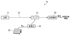
- FIG. 3 is an overall configuration diagram of an optical power feeding system 1a according to a second embodiment of the present invention.
- the optical power supply system 1a includes a light source 11, an optical power supply unit 20, an amplifier 31, an energy generator 32, a storage battery 33, and an optical power supply line 51.
- the configuration of the optical power supply system 1a in the second embodiment is different from the configuration of the optical power supply system 1 in the first embodiment described above.
- 33 is installed.
- the storage battery 33 stores electricity generated by the energy harvester 32. Further, the storage battery 33 supplies the stored power to the amplifier 31.
- W Env represents the amount of power generated by the energy harvester 32.
- the conversion efficiency of the amplifier 31 from electricity to light is A [%] and the conversion efficiency of the storage battery is B [%]
- the value of [W Env ⁇ A / 100 ⁇ B / 100] is W R
- the installation location and size of the energy harvester 32 are determined as described above. If the value of [W Env x A/100 x B/100] can be made equal to or greater than W R , then the output of the storage battery may be adjusted so that the amount of energy amplification by the amplifier 31 becomes W R.
- the storage battery 33 is installed in the middle of the path between the amplifier 31 and the energy harvester 32.
- the optical power supply system 1a in the second embodiment can be used when the amplifier 31 and the energy harvester 32 are directly connected like the optical power supply system 1 in the first embodiment described above. Compared to this, it is possible to supply power to the amplifier 31 more stably.
- FIG. 4 is an overall configuration diagram of an optical power feeding system 1b according to a third embodiment of the present invention.
- the optical power supply system 1b includes a light source 11, an optical power supply unit 20, an amplifier 31, an energy harvester 32, a storage battery 33, a storage battery use switching unit 40, and an optical power supply line 51. Equipped with
- the configuration of the optical power supply system 1b in the third embodiment differs from the configuration of the optical power supply system 1a in the second embodiment described above in that a storage battery use switching unit 40 is provided between the amplifier 31 and the energy harvester 32. (first switching section) is installed.
- the storage battery use switching unit 40 includes a switch 41p, a switch 41q, and a switch control unit 42.
- the switch 41p is a one-input, two-output switch, and can appropriately switch which output terminal is used among the two output terminals.
- the switch 41q is installed after the switch 41p.
- the switch 41q is a two-input, one-output switch, and can appropriately switch which input terminal to use out of the two input terminals.
- the switch control unit 42 controls switching of terminals by the switch 41p and the switch 41q according to the amount of power generated by the energy harvester 32.
- the switch control unit 42 stores power in the storage battery 33 and transfers power from the storage battery 33 to the amplifier 31.
- the switch 41p and the switch 41q are controlled so that power is supplied. That is, in this case, the switch control unit 42 controls so that the output of the switch 41p and the input of the switch 41q are both on the B side.
- the switch control unit 42 causes the power to be directly supplied from the energy harvester 32 to the amplifier 31.
- the switch 41p and the switch 41q are controlled so that the switch 41p and the switch 41q are controlled. That is, in this case, the switch control unit 42 controls so that the output of the switch 41p and the input of the switch 41q are both on the A side.
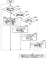
- FIG. 5 is a flowchart showing the operation of the switch control unit 42 of the optical power supply system 1b in the third embodiment of the present invention.
- the switch control unit 42 compares the amount of power generated by the energy harvester 32 and the amount of power required by the amplifier 31 (step S301). If the amount of power generated by the energy harvester 32 exceeds the amount of power required by the amplifier 31 (step S301, YES), the switch control unit 42 sets both the output of the switch 41p and the input of the switch 41p to the B side to perform energy harvesting. While charging the storage battery 33 by the device 32, control is performed so that power is supplied from the storage battery 33 to the amplifier 31 (step S302).
- the switch control unit 42 determines whether the amount of power generated by the energy harvester 32 is equal to or greater than a predetermined threshold. (Step S303). If the amount of power generated by the energy harvester 32 is equal to or greater than the predetermined threshold (step S303, YES), the switch control unit 42 sets both the output of the switch 41p and the input of the switch 41p to the A side, so that the power generation amount from the energy harvester 32 to the amplifier is Control is performed so that power is directly supplied to 31 (step S304). That is, if there is no surplus power but the amount of power generated by the energy harvester 32 is sufficient to power the amplifier 31, the switch control unit 42 causes the energy harvester 32 to directly supply power to the amplifier 31.
- step S303 - NO the switch control unit 42 determines whether the amount of electricity stored in the storage battery 33 is greater than or equal to the predetermined threshold (step S305). If the amount of electricity stored in the storage battery 33 is greater than or equal to the predetermined threshold (step S305, YES), the switch control unit 42 sets both the output of the switch 41p and the input of the switch 41p to the B side, so that power is not supplied from the storage battery 33 to the amplifier 31. Control is performed so as to (step S306).
- step S305, NO the switch control unit 42 sets both the output of the switch 41p and the input of the switch 41p to the A side, so that the energy harvester 32 is connected to the amplifier. Control is performed so that power is directly supplied to 31 (step S307).
- step S307 The reason why the switch control unit 42 operates as in step S307 above is that the amount of power generated by the energy harvester 32 is not sufficient to power the amplifier 31, and the amount of power stored in the storage battery 33 is not enough to power the amplifier 31. This is because if the route is made to go through the storage battery 33 if this is not sufficient, the power will be further insufficient due to conversion loss. Therefore, the switch control unit 42 controls the amplifier 31 to directly supply even a small amount of the generated power.
- the storage battery 33 and the storage battery use switching unit 40 (first switching unit) are installed in the path between the amplifier 31 and the energy harvester 32. be done.
- the optical power feeding system 1b stores electricity in the storage battery 33 when the amount of power generated by the energy harvester 32 exceeds the amount of power required by the amplifier 31 and there is surplus power. Power is supplied from the storage battery 33 to the amplifier 31, and when the power generation amount of the energy harvester 32 does not exceed the required power amount of the amplifier 31 and there is no surplus power, power is directly supplied from the energy harvester 32 to the amplifier 31. It can be controlled as follows.
- the optical power supply system 1b in the third embodiment can further stabilize the energy supply to the amplifier 31 compared to the optical power supply system 1 in the first embodiment and the optical power supply system 1a in the second embodiment. It can be done by
- FIG. 6 is an overall configuration diagram of an optical power feeding system 1c according to a fourth embodiment of the present invention.
- the optical power supply system 1c includes a light source 11, an optical power supply section 20, an amplifier 31, an energy generator 32, a storage battery 33, and an optical power supply line 51.
- the configuration of the optical power supply system 1c according to the fourth embodiment differs from the configuration of the optical power supply system 1 according to the first embodiment described above in that a storage battery 33 is installed after the optical power supply unit 20. be.
- the storage battery 33 stores electricity output from the optical power supply unit 20. Then, the storage battery 33 always outputs a certain amount of power to the power supply target devices in the power supply target area.
- the optical power supply system 1c in the fourth embodiment can stably supply power to the target even if the amount of power generated by the energy harvester 32 varies over time due to environmental changes, etc. Can power equipment.
- FIG. 7 is a diagram showing the overall configuration of an optical power feeding system 1d and the amount of energy within the optical fiber in the fifth embodiment of the present invention.
- the optical power supply system 1d includes a light source 11 provided in the station building, a light source 12 installed near the energy harvester 32, a light source determination unit 15, an optical power supply unit 20, It includes an amplifier 31, an energy harvester 32, and an optical power supply line 51.
- the configuration of the optical power supply system 1d in the fifth embodiment differs from the configuration of the optical power supply system 1 in the first embodiment described above in that a light source (light source 12) is also installed near the energy harvester 32. , further includes a light source determining section 15. The light source determining unit 15 determines whether the light source 11 or the light source 12 will perform optical power supply.
- the amount of energy supplied from the light source 11 at the point of the optical power supply section 20 is approximately 0 (a predetermined threshold value ⁇ ). (below). In this case, there is almost no advantage to using the light source 11 provided in the station building.
- the light source determination section 15 determines whether The power supply is switched to optical power supply using the light source 12 installed near the energy harvester 32. Note that the light source 12 is driven by electric power generated by the energy harvester 32. This allows the light source 12 to emit light even in non-electrified areas.
- the optical power feeding system 1d in the fifth embodiment can operate even when the distance between the light source 11 provided in the station building and the optical power feeding unit 20 is greater than a certain value. In optical power supply, the amount of power supplied can be increased without compromising safety.
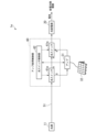
- FIG. 8 is an overall configuration diagram of an optical power feeding system 1e according to a sixth embodiment of the present invention.
- the optical power supply system 1e includes a light source 11, an optical power supply section 20, an amplifier 31, an energy harvester 32, an optical power supply line 51, and an amplifier use switching section 60.
- the configuration of the optical power supply system 1e in the sixth embodiment is different from the configuration of the optical power supply system 1 in the first embodiment described above.
- the main difference is that a switching section) is additionally installed.
- the amplifier use switching section 60 includes an optical switch 61p, an optical switch 61q, and an optical switch control section 62.
- the optical switch 61p is a one-input, two-output optical switch, and can appropriately switch which output terminal is used among the two output terminals.
- the optical switch 61q is installed after the optical switch 61p.
- the optical switch 61q is a two-input, one-output optical switch, and can appropriately switch which input terminal to use among the two input terminals.
- the optical switch control unit 62 controls switching of terminals by the optical switch 61p and the optical switch 61q according to the amplification amount of the amplifier 31.
- the light source 11 and the optical power supply unit 20 This is a form of direct connection without going through the network. That is, the light transmitted from the light source 11 is received by the optical power supply section 20 as it is. Further, when the output of the optical switch 61p is switched to the B side and the input of the optical switch 61q is switched to the B side, the light source 11 and the optical power supply section 20 are connected via the amplifier 31. It becomes a form. That is, the light transmitted from the light source 11 is amplified by the amplifier 31 and then received by the optical power supply section 20.
- the optical switch control unit 62 checks the amplification possible amount of the amplifier 31 at the current time, and if the amplification possible amount is equal to or greater than a predetermined threshold value ⁇ , the optical switch control unit 62 controls the optical switch 61p and the optical switch 61q to turn the amplifier 31 on. Form a route to take. On the other hand, if the amplification amount of the amplifier 31 at the current time is less than the predetermined threshold ⁇ , the optical switch control unit 62 controls the optical switch 61p and the optical switch 61q to form a path that does not go through the amplifier 31. do.
- the amplifier 31 Since the amplifier 31 is driven by the power supplied from the energy harvester 32, there is a possibility that the amplifier 31 will run into a power shortage due to a decrease in the power supply due to environmental changes or the like.
- the amplifier 31 When the amplifier 31 is not driven due to insufficient power supplied from the energy harvester 32, it functions not as an amplifier but as a strong attenuator.
- the optical power feeding system 1e in the sixth embodiment can switch to a route that does not go through the amplifier 31 when the amplifier 31 is not driven due to insufficient power supply.
- the optical power supply system 1e in the sixth embodiment can prevent the influence of amplifier connection loss caused by the connection of the amplifier 31 to the optical power supply line 51, so that energy can be transferred to the optical power supply unit 20 without excessive energy loss. can be supplied.
- the power for operating the optical switch 61p and the optical switch 61q may be provided by the energy generator 32. Furthermore, when power is not supplied to the optical switch 61p and the optical switch 61q, the optical switch 61p and the optical switch 61q are automatically switched to the A side (that is, the path does not go through the amplifier 31). configured.
- the configurations of the amplifier use switching unit 60 and the amplifier 31 of the optical power supply system 1e in the sixth embodiment can also be applied to the optical power supply systems in the first to fifth embodiments described above.
- the configuration of the amplifier 31 of the optical power supply system in the first to fifth embodiments described above may be replaced with a configuration that combines the amplifier use switching unit 60 and the amplifier 31 of the optical power supply system 1e in the sixth embodiment. .
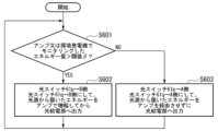
- FIG. 9 is a flowchart showing the operation of the optical switch control section 62 of the optical power supply system 1e in the sixth embodiment of the present invention.
- the optical switch control unit 62 determines whether the amount of energy monitored by the amplifier 31 or the energy harvester 32 exceeds a predetermined threshold value ⁇ (step S601). If the amount of energy monitored by the amplifier 31 or the energy harvester 32 exceeds the predetermined threshold ⁇ (step S601, YES), the optical switch control unit 62 sets both the output of the optical switch 61p and the input of the optical switch 61p to B. control so that the energy received from the light source 11 is amplified by the amplifier 31 and then supplied to the optical power supply section 20 (step S602).
- the optical switch control unit 62 controls the output of the optical switch 61p and the input of the optical switch 61p. Both are set to the A side, and the energy received from the light source 11 is controlled to be supplied to the optical power supply section 20 without passing through the amplifier 31 (step S603).
- the optical power supply system 1e when sufficient power is not supplied to the amplifier 31, the light transmitted from the amplifier does not pass through the amplifier 31.
- the configuration is such that the power is directly transmitted to the power feeding unit 20. With such a configuration, the optical power supply system 1e can prevent the amplifier 31 from functioning as an attenuator, and can stably supply power without compromising safety in optical power supply. can be increased.
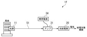
- FIG. 10 is an overall configuration diagram of an optical power feeding system 1f according to a seventh embodiment of the present invention.
- the optical power supply system 1f includes a light source 11, an optical power supply unit 20, an amplifier 31, a commercial power supply 34, and an optical power supply line 51.
- the configuration of the optical power supply system 1f in the seventh embodiment differs from the configuration of the optical power supply system 1 in the first embodiment described above in that a commercial power supply 34 is used instead of the energy harvester 32. It is. That is, in the seventh embodiment, unlike the first to sixth embodiments described above, it is assumed that the amplifier 31 is installed in an electrified area rather than a non-electrified area.
- the amplifier 31 is driven by power supplied from the commercial power supply 34. Note that if the installation location of the amplifier 31 is in an electrified area, it is considered possible to install a light source at the installation location of the amplifier 31. However, since a large laser is generally used as a light source, installation may be difficult due to restrictions on installation location and safety.
- the optical power feeding line 51 which is an optical transmission path connecting the light source 11 and the optical power feeding unit 20 that supplies power to the device to be powered, is midway along the path.
- An amplifier 31 (amplifier) is provided.
- the amplifier 31 performs energy amplification so as to replenish the amount of energy corresponding to the optical fiber loss occurring in the optical power supply line 51.
- the optical power feeding system 1f in the seventh embodiment has a long distance between the light source 11 and the optical power feeding section 20, and even if the optical fiber loss occurring in the optical power feeding line 51 is Even if the power supply area is large, sufficient power can be supplied to operate the equipment in the power supply target area.
- FIG. 11 is an overall configuration diagram of an optical power feeding system 1g according to the eighth embodiment of the present invention.
- the optical power supply system 1g includes a light source 11, a light source 13, an optical power supply section 20, an amplifier 31, a photoelectric conversion section 35, and an optical power supply line 51.
- the configuration of the optical power supply system 1f in the eighth embodiment is different from the configuration of the optical power supply system 1 in the first embodiment described above. The point is that it is used.
- the light source 13 is installed, for example, in a building such as a communication base station building. This station building is located in an electrified area, and is located far away from, for example, the photoelectric conversion unit 35 and the amplifier 31.
- the light source 13 sends out light for optical power supply toward the photoelectric conversion unit 35 .
- As the light for optical power supply for example, constantly lit light may be used.
- the light sent out by the light source 13 is transmitted to the photoelectric conversion unit 35 via an optical fiber.
- an SS (Single Star) configuration without branching is used for the purpose of reducing branching loss.
- the light source 11 emits light for operating the power supply target device driven by optical power supply by the optical power supply unit 20.
- the light source 13 sends out light for driving the amplifier 31 to the photoelectric conversion section 35 .
- the photoelectric conversion unit 35 receives the light sent from the light source 13, performs photoelectric conversion, and supplies power to the amplifier 31 through optical power supply. This drives the amplifier 31.
- the optical power feeding line 51 which is an optical transmission path connecting the light source 11 and the optical power feeding unit 20 that supplies power to the device to be powered, is midway along the path.
- An amplifier 31 (amplifier) is provided.
- the amplifier 31 performs energy amplification so as to replenish the amount of energy corresponding to the optical fiber loss occurring in the optical power supply line 51.
- the optical power feeding system 1g in the eighth embodiment has, for example, a long distance between the light source 11 and the optical power feeding unit 20, and even if the optical fiber loss occurring in the optical power feeding line 51 is Even if the power supply area is large, sufficient power can be supplied to operate the equipment in the power supply target area.
- FIG. 12 is a diagram showing an embodiment of the present invention.
- the distance between the light source 11 and the amplifier 31 is 10 [km].
- the optical fiber loss occurring in the optical power supply line 51 is 0.3 [dB/km].
- the fiber fuse phenomenon a phenomenon in which the fiber melts
- the power generation amount of two commercially available solar cells with a size of 1.2 [m] x 0.5 [m] is about 200 [W]. If the average power generation amount per day, taking into account nighttime and rainy weather, is set to 1/10 of 200 [W], it is possible to supply an average of 20 [W] of energy from this solar cell. If the power conversion efficiency in the amplifier 31 is assumed to be 4%, it is possible to supply 0.8W to the optical fiber. If the amplifier connection loss caused by connecting the amplifier 31 to the optical power supply line 51 is 0.5 [dB] or less, theoretically, the above-mentioned energy attenuation (0.75 [W]) It is possible to supplement.
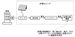
- FIGS. 13 and 14 are diagrams showing an example of introducing an optical power supply system in an embodiment of the present invention.
- FIG. 13 shows an example where the amplifier 31 is installed in a non-electrified area
- FIG. 14 shows an example where the amplifier 31 is installed in an electrified area.
- the optical power feeding system shown in FIG. 13 is configured to include a light source installed in a station building in an electrified area, an amplifier, a light receiving end, a battery, and a power feeding target device in a non-electrified area. Since the amplifier is located in a non-electrified area, the power to drive the amplifier is supplied by an energy harvester that can generate electricity even in non-electrified areas.
- the optical power feeding system shown in FIG. 14 includes a light source and amplifier installed in a station building in an electrified area, and a light receiving end, battery, and power feeding target equipment in a non-electrified area. Since the amplifier is located in an electrified area, the power to drive the amplifier can be supplied from a commercial power source.
- the optical power feeding system includes a light source, an amplifier, and an optical power feeding section.
- the optical power supply system is the optical power supply system 1, 1a to 1g in the embodiment
- the light source is the light source 11 in the embodiment
- the amplifier is the amplifier 31 in the embodiment
- the optical power supply unit is the optical power supply system 1, 1a to 1g in the embodiment.
- the light source sends out light for optical power supply to the optical power supply line connected to the optical power supply unit.
- the optical power supply line is the optical power supply line 51 in the embodiment.
- the amplifier is installed along the path of the optical power supply line and amplifies the light sent out from the light source.
- the optical power supply section receives light amplified by an amplifier, performs photoelectric conversion on the light, and obtains electric power.
- optical power supply line may be a line with a single star configuration.
- the optical power supply system described above may further include an energy harvester.
- the energy harvester is the energy harvester 32 in the embodiment.
- the energy harvester 32 generates electricity by energy harvesting.
- the above amplifier may be driven by electricity obtained from an energy harvester.
- the above amplifier may supplement power lost due to optical fiber loss occurring between the light source and the optical power supply section.
- W C represents the amount of power lost when the amplifier is connected to the optical power supply line
- E MAX represents the upper limit of the power that can be input to the optical power supply line
- E Amp represents the amount of power lost when the amplifier is connected to the optical power supply line. Represents the power of the power supply line.
- the optical power feeding system described above may further include a first switching section.
- the first switching section is the storage battery use switching section 40 in the embodiment.
- the first switching unit may switch the path between the energy harvester and the amplifier to either a path that passes through a storage battery or a path that does not go through a storage battery, depending on the amount of power generated by the energy harvester.
- the storage battery described above is provided between the energy harvester and the amplifier, stores electricity acquired from the energy harvester, and sends the stored electricity to the amplifier.
- the optical power supply system described above may further include a second switching section.
- the second switching section switches the path between the light source and the optical power feeding section to either a path that passes through the amplifier or a path that does not go through the amplifier, depending on the amount of power that can be amplified by the amplifier.
- Part of the configuration of the optical power supply system 1 and the optical power supply systems 1a to 1g in the embodiments described above may be realized by a computer.
- a program for realizing this function may be recorded on a computer-readable recording medium, and the program recorded on the recording medium may be read into a computer system and executed.
- the "computer system” herein includes hardware such as an OS and peripheral devices.
- the term "computer-readable recording medium” refers to portable media such as flexible disks, magneto-optical disks, ROMs, and CD-ROMs, and storage devices such as hard disks built into computer systems.
- a "computer-readable recording medium” refers to a storage medium that dynamically stores a program for a short period of time, such as a communication line when transmitting a program via a network such as the Internet or a communication line such as a telephone line. It may also include a device that retains a program for a certain period of time, such as a volatile memory inside a computer system that is a server or client in that case. Further, the above-mentioned program may be one for realizing a part of the above-mentioned functions, or may be one that can realize the above-mentioned functions in combination with a program already recorded in the computer system. It may be realized using a programmable logic device such as an FPGA (Field Programmable Gate Array).
- FPGA Field Programmable Gate Array
Landscapes
- Physics & Mathematics (AREA)
- Electromagnetism (AREA)
- Engineering & Computer Science (AREA)
- Computer Networks & Wireless Communication (AREA)
- Signal Processing (AREA)
- Optical Communication System (AREA)
Priority Applications (3)
| Application Number | Priority Date | Filing Date | Title |
|---|---|---|---|
| US19/101,287 US20260046036A1 (en) | 2022-09-13 | 2022-09-13 | Optical power supply method and optical power supply system |
| JP2024546536A JP7807697B2 (ja) | 2022-09-13 | 2022-09-13 | 光給電方法及び光給電システム |
| PCT/JP2022/034144 WO2024057378A1 (ja) | 2022-09-13 | 2022-09-13 | 光給電方法及び光給電システム |
Applications Claiming Priority (1)
| Application Number | Priority Date | Filing Date | Title |
|---|---|---|---|
| PCT/JP2022/034144 WO2024057378A1 (ja) | 2022-09-13 | 2022-09-13 | 光給電方法及び光給電システム |
Publications (1)
| Publication Number | Publication Date |
|---|---|
| WO2024057378A1 true WO2024057378A1 (ja) | 2024-03-21 |
Family
ID=90274413
Family Applications (1)
| Application Number | Title | Priority Date | Filing Date |
|---|---|---|---|
| PCT/JP2022/034144 Ceased WO2024057378A1 (ja) | 2022-09-13 | 2022-09-13 | 光給電方法及び光給電システム |
Country Status (3)
| Country | Link |
|---|---|
| US (1) | US20260046036A1 (https=) |
| JP (1) | JP7807697B2 (https=) |
| WO (1) | WO2024057378A1 (https=) |
Citations (2)
| Publication number | Priority date | Publication date | Assignee | Title |
|---|---|---|---|---|
| JP2006067014A (ja) * | 2004-08-24 | 2006-03-09 | Sumitomo Electric Ind Ltd | 光通信機器および光伝送システム |
| WO2011158283A1 (ja) * | 2010-06-14 | 2011-12-22 | 富士通テレコムネットワークス株式会社 | 光伝送システム |
-
2022
- 2022-09-13 US US19/101,287 patent/US20260046036A1/en active Pending
- 2022-09-13 WO PCT/JP2022/034144 patent/WO2024057378A1/ja not_active Ceased
- 2022-09-13 JP JP2024546536A patent/JP7807697B2/ja active Active
Patent Citations (2)
| Publication number | Priority date | Publication date | Assignee | Title |
|---|---|---|---|---|
| JP2006067014A (ja) * | 2004-08-24 | 2006-03-09 | Sumitomo Electric Ind Ltd | 光通信機器および光伝送システム |
| WO2011158283A1 (ja) * | 2010-06-14 | 2011-12-22 | 富士通テレコムネットワークス株式会社 | 光伝送システム |
Also Published As
| Publication number | Publication date |
|---|---|
| JPWO2024057378A1 (https=) | 2024-03-21 |
| JP7807697B2 (ja) | 2026-01-28 |
| US20260046036A1 (en) | 2026-02-12 |
Similar Documents
| Publication | Publication Date | Title |
|---|---|---|
| US6038356A (en) | Lightwave transmission system employing raman and rare-earth doped fiber amplification | |
| US7508575B2 (en) | Cascaded pump delivery for remotely pumped erbium-doped fiber amplifiers | |
| CN207135105U (zh) | 一种多波长无中继传输系统 | |
| EP4149023B1 (en) | Pse device and powered device of optical power supply system, and optical power supply system | |
| CN113783317B (zh) | 基于少模光纤的能信共传系统和方法 | |
| CN107658927A (zh) | 基于反馈信令的自适应移动光学充电系统 | |
| Souza et al. | Analog response in optically powered radio-over-fiber links with distributed amplification in single-mode fibers | |
| US20220021453A1 (en) | Powered device and power sourcing equipment of optical power supply system, and optical power supply system | |
| JP7807697B2 (ja) | 光給電方法及び光給電システム | |
| Mohammed et al. | Power over fiber for internet of things application | |
| CN109819509B (zh) | 一种能量收集解码-转发中继系统的功率在线控制方法 | |
| US6909535B2 (en) | Optical communication system employing raman amplification | |
| CN113411132B (zh) | 多功能光中继器系统 | |
| US7146071B2 (en) | Optical transmission system | |
| EP1560065A1 (en) | Optical amplification safety control method and apparatus | |
| KR100976814B1 (ko) | 태양전지를 이용한 무선중계기 | |
| Yasui et al. | A Stable 2-W supply optical powering system | |
| US6711359B1 (en) | Optical fiber communication system employing doped optical fiber and Raman amplification | |
| Cai | SDM and Parallelism in Submarine Cable Systems | |
| CN117834040B (zh) | 一种新能源远程有线通信中继节点供电系统及方法 | |
| CN1265475A (zh) | 增益控制光放大器 | |
| US20260095257A1 (en) | Power transmission over optical fiber | |
| CN1240944A (zh) | 光纤通信的方法和供此方法使用的终端装置和系统 | |
| WO2024057651A1 (ja) | 光給電方法、光給電システム及び光給電装置 | |
| KR20240072420A (ko) | 태양전지를 이용한 무선중계기 |
Legal Events
| Date | Code | Title | Description |
|---|---|---|---|
| 121 | Ep: the epo has been informed by wipo that ep was designated in this application |
Ref document number: 22958713 Country of ref document: EP Kind code of ref document: A1 |
|
| WWE | Wipo information: entry into national phase |
Ref document number: 2024546536 Country of ref document: JP |
|
| NENP | Non-entry into the national phase |
Ref country code: DE |
|
| 122 | Ep: pct application non-entry in european phase |
Ref document number: 22958713 Country of ref document: EP Kind code of ref document: A1 |