WO2024048568A1 - 酸性ガス回収システム - Google Patents
酸性ガス回収システム Download PDFInfo
- Publication number
- WO2024048568A1 WO2024048568A1 PCT/JP2023/031181 JP2023031181W WO2024048568A1 WO 2024048568 A1 WO2024048568 A1 WO 2024048568A1 JP 2023031181 W JP2023031181 W JP 2023031181W WO 2024048568 A1 WO2024048568 A1 WO 2024048568A1
- Authority
- WO
- WIPO (PCT)
- Prior art keywords
- gas
- acidic gas
- adsorption
- acidic
- desorption
- Prior art date
- Legal status (The legal status is an assumption and is not a legal conclusion. Google has not performed a legal analysis and makes no representation as to the accuracy of the status listed.)
- Ceased
Links
Images


Classifications
-
- B—PERFORMING OPERATIONS; TRANSPORTING
- B01—PHYSICAL OR CHEMICAL PROCESSES OR APPARATUS IN GENERAL
- B01D—SEPARATION
- B01D53/00—Separation of gases or vapours; Recovering vapours of volatile solvents from gases; Chemical or biological purification of waste gases, e.g. engine exhaust gases, smoke, fumes, flue gases, aerosols
- B01D53/02—Separation of gases or vapours; Recovering vapours of volatile solvents from gases; Chemical or biological purification of waste gases, e.g. engine exhaust gases, smoke, fumes, flue gases, aerosols by adsorption, e.g. preparative gas chromatography
- B01D53/04—Separation of gases or vapours; Recovering vapours of volatile solvents from gases; Chemical or biological purification of waste gases, e.g. engine exhaust gases, smoke, fumes, flue gases, aerosols by adsorption, e.g. preparative gas chromatography with stationary adsorbents
- B01D53/0462—Temperature swing adsorption
-
- B—PERFORMING OPERATIONS; TRANSPORTING
- B01—PHYSICAL OR CHEMICAL PROCESSES OR APPARATUS IN GENERAL
- B01D—SEPARATION
- B01D53/00—Separation of gases or vapours; Recovering vapours of volatile solvents from gases; Chemical or biological purification of waste gases, e.g. engine exhaust gases, smoke, fumes, flue gases, aerosols
- B01D53/02—Separation of gases or vapours; Recovering vapours of volatile solvents from gases; Chemical or biological purification of waste gases, e.g. engine exhaust gases, smoke, fumes, flue gases, aerosols by adsorption, e.g. preparative gas chromatography
- B01D53/04—Separation of gases or vapours; Recovering vapours of volatile solvents from gases; Chemical or biological purification of waste gases, e.g. engine exhaust gases, smoke, fumes, flue gases, aerosols by adsorption, e.g. preparative gas chromatography with stationary adsorbents
- B01D53/0407—Constructional details of adsorbing systems
- B01D53/0446—Means for feeding or distributing gases
-
- B—PERFORMING OPERATIONS; TRANSPORTING
- B01—PHYSICAL OR CHEMICAL PROCESSES OR APPARATUS IN GENERAL
- B01D—SEPARATION
- B01D53/00—Separation of gases or vapours; Recovering vapours of volatile solvents from gases; Chemical or biological purification of waste gases, e.g. engine exhaust gases, smoke, fumes, flue gases, aerosols
- B01D53/34—Chemical or biological purification of waste gases
- B01D53/46—Removing components of defined structure
- B01D53/62—Carbon oxides
-
- B—PERFORMING OPERATIONS; TRANSPORTING
- B01—PHYSICAL OR CHEMICAL PROCESSES OR APPARATUS IN GENERAL
- B01D—SEPARATION
- B01D53/00—Separation of gases or vapours; Recovering vapours of volatile solvents from gases; Chemical or biological purification of waste gases, e.g. engine exhaust gases, smoke, fumes, flue gases, aerosols
- B01D53/34—Chemical or biological purification of waste gases
- B01D53/96—Regeneration, reactivation or recycling of reactants
-
- B—PERFORMING OPERATIONS; TRANSPORTING
- B01—PHYSICAL OR CHEMICAL PROCESSES OR APPARATUS IN GENERAL
- B01D—SEPARATION
- B01D2257/00—Components to be removed
- B01D2257/50—Carbon oxides
- B01D2257/504—Carbon dioxide
-
- C—CHEMISTRY; METALLURGY
- C01—INORGANIC CHEMISTRY
- C01B—NON-METALLIC ELEMENTS; COMPOUNDS THEREOF; METALLOIDS OR COMPOUNDS THEREOF NOT COVERED BY SUBCLASS C01C
- C01B32/00—Carbon; Compounds thereof
- C01B32/50—Carbon dioxide
-
- Y—GENERAL TAGGING OF NEW TECHNOLOGICAL DEVELOPMENTS; GENERAL TAGGING OF CROSS-SECTIONAL TECHNOLOGIES SPANNING OVER SEVERAL SECTIONS OF THE IPC; TECHNICAL SUBJECTS COVERED BY FORMER USPC CROSS-REFERENCE ART COLLECTIONS [XRACs] AND DIGESTS
- Y02—TECHNOLOGIES OR APPLICATIONS FOR MITIGATION OR ADAPTATION AGAINST CLIMATE CHANGE
- Y02C—CAPTURE, STORAGE, SEQUESTRATION OR DISPOSAL OF GREENHOUSE GASES [GHG]
- Y02C20/00—Capture or disposal of greenhouse gases
- Y02C20/40—Capture or disposal of greenhouse gases of CO2
Definitions
- the present invention relates to an acid gas recovery system.
- Such acidic gases mainly include carbon dioxide (hereinafter sometimes referred to as CO 2 ), which causes global warming.
- CO 2 carbon dioxide
- a carbon dioxide capture, utilization, and storage (CCUS) cycle is known as a typical example of such an approach.
- CCUS carbon dioxide capture, utilization, and storage
- a gas separation unit including an adsorbent layer filled with pellet-like carbon dioxide adsorbent has been proposed (see, for example, Patent Document 1). .
- a pelleted carbon dioxide adsorbent adsorbs CO2 from a gaseous fluid passing through the adsorbent layer at a predetermined adsorption temperature, and when heated to a desorption temperature exceeding the adsorption temperature, the adsorbed CO2 is removed.
- Detach 2 In order to provide a CO 2 recovery system at low cost, it is conceivable to reduce the number of CO 2 supply blowers and distribute and supply desorbed gas to each of a plurality of CO 2 adsorption devices. However, the plurality of CO 2 adsorption devices may have different flow path resistances (pressure losses).
- the flow rate of the desorption gas to the CO 2 adsorption device with relatively low flow path resistance is relatively large, and the flow rate of the desorption gas to the CO 2 adsorption device with relatively high flow path resistance is relatively large. Flow rate becomes relatively low. Then, temperature unevenness occurs between the plurality of CO 2 adsorption devices depending on the flow rate of the desorbed gas, and the temperature of the CO 2 adsorption device with relatively low flow path resistance may rise excessively. If the temperature of the CO 2 adsorption device increases excessively, the CO 2 adsorption material will deteriorate due to volatilization, thermal decomposition, etc., and the CO 2 adsorption capacity will decrease. Further, in a CO 2 adsorption device having a relatively high flow path resistance, there is a problem that the temperature is low and the temperature required for CO 2 removal cannot be reached, resulting in a decrease in the CO 2 adsorption capacity.
- the main object of the present invention is to provide an acidic gas recovery system that can improve the amount of acidic gas adsorbed and suppress deterioration of the acidic gas adsorbent.
- An acidic gas recovery system includes a plurality of acidic gas adsorption devices and a fluid supply line.
- Each of the plurality of acid gas adsorption devices includes an acid gas adsorbent.
- the fluid supply line distributes and supplies fluid to each of the plurality of acid gas adsorption devices.
- the fluid supply line includes a branch section and a plurality of branch sections.
- Each of the plurality of branch parts connects the branch part and each of the plurality of acid gas adsorption devices.
- a resistor is provided in each of the plurality of branch parts.
- the acidic gas may be carbon dioxide.
- a target gas containing acidic gas is supplied to the plurality of acidic gas adsorption devices, and the acidic gas is adsorbed by the acidic gas adsorbent.
- a desorption step of heating the plurality of acidic gas adsorption devices to desorb the acidic gas from the acidic gas adsorbent, and supplying the desorption gas to the plurality of acidic gas adsorption devices; may be possible.
- the flow path resistance of the resistor may be greater than the flow path resistance of each of the plurality of acidic gas adsorption devices.
- the resistor may be capable of varying flow path resistance. In the adsorption step, the flow path resistance of the resistor is smaller than the flow path resistance of each of the plurality of acidic gas adsorption devices.
- the acidic gas recovery system described in [4] above may further include a control section. The control unit can control the flow path resistance of the resistor.
- the acidic gas recovery system according to any one of [3] to [5] above may further include a detour line that can bypass the resistor.
- an acid gas recovery system that can improve the amount of acid gas adsorbed and suppress deterioration of the acid gas adsorbent.
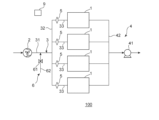
- FIG. 1 is a schematic configuration diagram of an acid gas recovery system according to one embodiment of the present invention.
- FIG. 2 is a schematic configuration diagram of an embodiment of an acid gas adsorption device included in the acid gas recovery system of FIG.
- FIG. 3 is a schematic perspective view of another embodiment of the acid gas adsorption device included in the acid gas recovery system of FIG. 1.
- FIG. 4 is a schematic cross-sectional view of the acid gas adsorption device of FIG. 3.
- FIG. 5 is a schematic configuration diagram of an acid gas recovery system according to another embodiment of the present invention.
- FIG. 1 is a schematic configuration diagram of an acid gas recovery system according to one embodiment of the present invention.
- the illustrated acidic gas recovery system 100 includes a plurality of acidic gas adsorption devices 1 and a fluid supply line 3.
- Each of the plurality of acid gas adsorption devices 1 includes an acid gas adsorbent.
- the fluid supply line 3 distributes and supplies fluid to each of the plurality of acid gas adsorption devices 1 .
- the fluid supply line 3 includes a branch section 32 and a plurality of branch sections 33.
- Each of the plurality of branching sections 33 connects the branching section 32 and each of the plurality of acid gas adsorption devices 1.
- a resistor 5 is provided in each of the plurality of flow dividers 33.
- the acid gas recovery system 100 can typically perform an adsorption process and a desorption process. Although details will be described later, in the adsorption step, a target gas containing acidic gas is supplied to the plurality of acidic gas adsorption devices 1, and the acidic gas is adsorbed by the acidic gas adsorbent. In the desorption step, the plurality of acidic gas adsorption devices 1 are heated to desorb acidic gas from the acidic gas adsorbent, and the desorption gas is supplied to the plurality of acidic gas adsorption devices 1. According to one embodiment of the present invention, a plurality of acid gas adsorption devices 1 are connected to the fluid supply line 3 in parallel.
- the fluid supply line 3 can distribute and supply the gas to be treated to each of the plurality of acid gas adsorption devices 1 in the adsorption step.
- acidic gas can be adsorbed all at once by the acidic gas adsorbents of the plurality of acidic gas adsorption devices 1, and the number of blowers for supplying acidic gas can be reduced, providing an inexpensive acidic gas recovery system.
- the plurality of acidic gas adsorption devices 1 are heated, and the fluid supply line 3 distributes and supplies the desorption gas to each of the plurality of acidic gas adsorption devices 1.
- the plurality of acid gas adsorption devices may have different flow path resistances (pressure losses).
- the flow rate of desorption gas to the acidic gas adsorption device with relatively low flow path resistance is relatively large, and the flow rate of desorption gas to the acidic gas adsorption device with relatively high flow path resistance is relatively large. Flow rate becomes relatively low. Then, temperature unevenness occurs between the plurality of acidic gas adsorption devices depending on the flow rate of the desorbed gas, and the temperature of the acidic gas adsorption device having a relatively low flow path resistance may rise excessively. If the temperature of the acid gas adsorption device increases excessively, the acid gas adsorbent deteriorates due to volatilization, thermal decomposition, etc., and the acid gas adsorption capacity decreases.
- the resistor 5 is provided in the branch section 33 that connects the branch section 32 and each acidic gas adsorption device 1. Therefore, the flow rate of the desorption gas flowing through each acidic gas adsorption device 1 depends on the flow path resistance of the resistor 5 rather than the flow path resistance (pressure loss) of the plurality of acidic gas adsorption devices 1.
- the flow path resistance of the resistor 5 in the desorption step is greater than the flow path resistance of each of the plurality of acid gas adsorption devices 1.
- the flow path resistance of the resistor 5 in the desorption step is, for example, 0.001 kPaG (gauge pressure) or more, preferably 0.1 kPaG or more, and is, for example, 5 kPaG or less, preferably 1 kPaG or less.
- Flow path resistance is pressure drop resistance, and can be measured, for example, by differential pressure gauges installed before and after the resistor and before and after the acid gas adsorption device.
- the difference between the flow path resistance of the resistor 5 and the flow path resistance of the acidic gas adsorption device 1 is, for example, 0.01 kPaG (gauge pressure) or more, preferably 0.1 kPaG or more, and, for example, 4.5 kPaG or less, preferably 0. .9 kPaG or less. If the flow path resistance of the resistor in the desorption process and/or the difference between the flow path resistance between the resistor and the acidic gas adsorption device is greater than or equal to the above lower limit, then the flow path resistance of the acidic gas adsorption device is equal to the flow rate of the desorbed gas.
- the desorption gas can be used energetically in the desorption process. It can be supplied to acid gas adsorption equipment within a certain range.
- the friction loss coefficient of the resistor 5 through which the desorption gas passes is, for example, 0.020 to 2.000, preferably 0.023 to 1.500.
- the friction loss coefficient is typically determined from the Colebrook equation or Moody diagram.
- the friction loss coefficient of the acid gas adsorption device 1 through which the desorption gas passes is, for example, 0.010 to 0.500, preferably 0.015 to 0.350.
- the resistor 5 can vary the flow path resistance.
- the flow path resistance of the resistor 5 in the adsorption step is preferably as low as possible, and is typically smaller than the flow path resistance of the resistor 5 in the desorption step.
- the flow path resistance of the resistor 5 in the adsorption step is, for example, 20 kPaG (gauge pressure) or less, preferably 1 kPaG or less, more preferably 0.1 kPaG or less, further preferably 0.08 kPaG or less, particularly preferably 0.0008 kPaG or less. .
- the gas to be treated can be efficiently supplied to each acidic gas adsorption device in the adsorption step.
- the lower limit of the flow path resistance of the resistor in the adsorption step is, for example, 0.0001 kPaG or more, and for example, 0.01 kPaG or more.
- the flow path resistance of the resistor 5 in the adsorption step is smaller than the flow path resistance of each of the plurality of acid gas adsorption devices 1. Thereby, the gas to be treated can be supplied to the acidic gas adsorption device even more efficiently.
- the friction loss coefficient of the resistor 5 through which the gas to be treated passes is, for example, 0.010 to 0.050, preferably 0.015 to 0.045.
- the friction loss coefficient of the acid gas adsorption device 1 through which the gas to be treated passes is, for example, 0.010 to 0.050, preferably 0.013 to 0.045.
- the acid gas recovery system 100 may further include a detour line 34 that detours around the resistor 5. This allows the resistor 5 to be bypassed by switching the flow path. Therefore, in the adsorption step, the target gas can be efficiently supplied to each acidic gas adsorption device via the detour line.
- the flow path resistance (pressure loss) of the resistor 5 may be constant during the adsorption process and the desorption process.
- its range is, for example, the same as the range of the flow path resistance of the resistor 5 in the above-described desorption step.
- acidic gases contained in the gas to be treated include carbon dioxide (CO 2 ), hydrogen sulfide, sulfur dioxide, nitrogen dioxide, dimethyl sulfide (DMS), and hydrogen chloride.
- the acidic gas is carbon dioxide ( CO2 ) and the gas to be treated is a CO2- containing gas.
- the CO 2 -containing gas may contain nitrogen in addition to CO 2 .
- the CO2 - containing gas is typically air (atmosphere).
- the CO 2 concentration in the CO 2 -containing gas is, for example, 100 ppm (volume basis) or more and 2 volume % or less.
- the illustrated acidic gas recovery system 100 includes, in addition to the plurality of acidic gas adsorption devices 1, the fluid supply line 3, and the plurality of resistors 5 described above, an acidic gas supply blower 2, a desorption gas supply unit 6, and the like. , and a collection unit 4.
- the acidic gas adsorption device 1 is a carbon dioxide adsorption device 1a.
- the illustrated acidic gas recovery system 100 includes four acidic gas adsorption devices 1, the number of acidic gas adsorption devices 1 is not limited to this. The number of acid gas adsorption devices 1 is, for example, 2 or more, preferably 4 or more, and, for example, 10 or less.
- the acid gas adsorption apparatus 1 includes a plurality of adsorbent layers 71.
- the plurality of adsorbent layers 71 are stacked at intervals in their thickness direction. In the illustrated example, five adsorbent layers 71 are arranged in parallel, but the number of adsorbent layers 71 is not limited to this.
- the number of adsorbent layers 71 is, for example, 5 or more, preferably 10 or more, and more preferably 20 or more.
- the interval between adjacent adsorbent layers 71 among the plurality of adsorbent layers 71 is, for example, 0.5 cm or more and 1.5 cm or less.
- Each of the plurality of adsorbent layers 71 includes a flexible fiber member 73 and a plurality of pellet-like adsorbents 72.
- the flexible fiber member 73 allows the passage of gas and restricts the passage of the pellet-like adsorbent.
- the flexible fiber member 73 is typically formed into a hollow shape (bag shape) capable of accommodating a plurality of pellet-like adsorbents 72.
- the flexible fiber member 73 may be a woven fabric or a nonwoven fabric.
- Examples of the material for the flexible fiber member 73 include organic fibers and natural fibers, preferably polyethylene terephthalate fibers, polyethylene fibers, and cellulose fibers.
- the thickness of the flexible fiber member 73 is, for example, 25 ⁇ m or more and 500 ⁇ m or less.
- a plurality of pellet-like adsorbents 72 are filled inside a flexible fiber member 73 having a hollow shape (bag shape).
- the pellet-like adsorbent 72 functions as an acidic gas adsorbent, and typically functions as a carbon dioxide adsorbent.
- Examples of the material for the pellet-like adsorbent 72 include amine-modified materials, preferably amine-modified cellulose, and more preferably amine-modified nanofibrous cellulose.
- the average primary particle diameter of the pellet-like adsorbent 72 is, for example, 60 ⁇ m or more and 1200 ⁇ m or less.
- the filling ratio of the pellet-like adsorbent 72 in the adsorbent layer 71 may be any appropriate value.
- the illustrated acidic gas adsorption device 1 further includes a plurality of spacers 74.
- the spacer 74 is sandwiched between adjacent adsorbent layers 71 among the plurality of adsorbent layers 71 . This makes it possible to stably ensure the spacing between adjacent adsorbent layers.
- the plurality of adsorbent layers 71 and the plurality of spacers 74 have an approximately 99-fold shape when viewed from a direction perpendicular to the thickness direction of the adsorbent layer 71 (the depth direction of the paper plane in FIG. 1). It is arranged so that
- an acid gas adsorption apparatus 1 includes a base material 10 and an acid gas adsorption layer 15.
- the structure of the base material 10 is not particularly limited, and includes, for example, a honeycomb shape, a filter structure such as a filter cloth, a pellet structure, and the like.
- the acidic gas adsorption layer 15 is not particularly limited as long as it is placed on the surface of the base material 10.
- the base material 10 is a honeycomb-shaped base material 10a.
- the honeycomb-shaped base material 10a includes partition walls 13 that define a plurality of cells 14.
- the cells 14 extend from the first end face E1 (inflow end face) to the second end face E2 (outflow end face) of the honeycomb base material 10a in the length direction (axial direction) of the honeycomb base material 10a (see FIG. 4). ).
- the cells 14 have any suitable shape in a cross section taken in a direction perpendicular to the length direction of the honeycomb-shaped base material 10a.
- Examples of the cross-sectional shape of the cell include a triangle, a quadrangle, a pentagon, a hexagon or more polygon, a circle, and an ellipse. All of the cross-sectional shapes and sizes of the cells may be the same, or at least some of them may be different. Among the cross-sectional shapes of such cells, preferred are hexagons and quadrangles, and more preferred are squares, rectangles, and hexagons.
- the cell density (that is, the number of cells 14 per unit area) in the cross section of the honeycomb-shaped base in the direction perpendicular to the length direction can be appropriately set depending on the purpose.
- the cell density may be, for example, from 4 cells/cm 2 to 320 cells/cm 2 . If the cell density is within this range, sufficient strength and effective GSA (geometric surface area) of the honeycomb-like base material can be ensured.
- the honeycomb-shaped base material 10a has any suitable shape (overall shape).
- Examples of the shape of the honeycomb-like base material include a columnar shape with a circular bottom surface, an elliptic columnar shape with an elliptical bottom surface, a prismatic shape with a polygonal bottom surface, and a columnar shape with an irregular bottom surface.
- the honeycomb-shaped base material 10a in the illustrated example has a cylindrical shape.
- the outer diameter and length of the honeycomb-shaped base material can be appropriately set depending on the purpose.
- the honeycomb-shaped base material may have a hollow region at its center in a cross section taken in a direction perpendicular to the length direction.
- the honeycomb-shaped base material 10a typically includes an outer peripheral wall 11 and partition walls 13 located inside the outer peripheral wall 11.
- the outer peripheral wall 11 and the partition wall 13 are integrally formed.
- the outer peripheral wall 11 and the partition wall 13 may be separate bodies.
- the outer peripheral wall 11 has a cylindrical shape.
- the thickness of the outer peripheral wall 11 can be arbitrarily and appropriately set.
- the thickness of the outer peripheral wall 11 is, for example, 0.1 mm to 10 mm.
- the partition wall 13 defines a plurality of cells 14. More specifically, the partition 13 has a first partition 13 a and a second partition 13 b that are orthogonal to each other, and the first partition 13 a and the second partition 13 b define a plurality of cells 14 .
- the cross-sectional shape of the cell 14 is a quadrilateral except for the portion where the first partition wall 13a and the second partition wall 13b contact the outer peripheral wall 11. Note that the configuration of the partition wall is not limited to the partition wall 13 described above.
- the partition wall may include a first partition wall extending in the radial direction and a second partition wall extending in the circumferential direction, which may define a plurality of cells.
- the thickness of the partition walls 13 can be appropriately set depending on the use of the honeycomb-shaped base material.
- the thickness of the partition wall 13 is typically thinner than the thickness of the outer peripheral wall 11.
- the thickness of the partition wall 13 is, for example, 0.03 mm to 0.6 mm.
- the thickness of the partition wall is measured by, for example, cross-sectional observation using a SEM (scanning electron microscope). If the thickness of the partition walls is within this range, the mechanical strength of the honeycomb-like base material can be made sufficient, and the opening area (the total area of cells in the cross section) can be made sufficient. can.
- the porosity of the partition wall 13 can be appropriately set depending on the purpose.
- the porosity of the partition wall 13 is, for example, 15% or more, preferably 20% or more, and is, for example, 70% or less, preferably 45% or less. Note that the porosity can be measured, for example, by mercury porosimetry.
- the bulk density of the partition wall 13 can be appropriately set depending on the purpose. Their bulk density is, for example, 0.10 g/cm 3 or more, preferably 0.20 g/cm 3 or more, and, for example, 0.60 g/cm 3 or less, preferably 0.50 g/cm 3 or less. Note that the bulk density can be measured, for example, by mercury porosimetry.
- a typical material for forming the partition wall 13 is ceramics.
- ceramics include silicon carbide, silicon-silicon carbide composite materials, cordierite, mullite, alumina, silicon nitride, spinel, silicon carbide-cordierite composite materials, lithium aluminum silicate, and aluminum titanate.
- the materials constituting the partition wall can be used alone or in combination.
- preferred are cordierite, alumina, mullite, silicon carbide, silicon-silicon carbide composite materials, and silicon nitride, and more preferred are silicon carbide and silicon-carbide. Examples include silicon-based composite materials.
- Such a honeycomb-shaped base material 10a is typically produced by the following method. First, a binder and water or an organic solvent are added as necessary to the material powder containing the ceramic powder described above, the resulting mixture is kneaded to form a clay, and the clay is molded into a desired shape (typically (extrusion molding), followed by drying and, if necessary, firing, to produce the honeycomb-shaped base material 10a. When firing, it is fired at, for example, 1200°C to 1500°C. The firing time is, for example, 1 hour or more and 20 hours or less.
- the acidic gas adsorption layer 15 is formed on the surface of the partition wall 13.
- a gas flow path 16 is formed in a section of the cell 14 where the acid gas adsorption layer 15 is not formed (typically in the center).
- the acidic gas adsorption layer 15 may be formed on the entire inner surface of the partition wall 13 (that is, so as to surround the gas flow path 16) as in the illustrated example, or may be formed on a part of the surface of the partition wall.
- the removal efficiency of acidic gas typically CO 2
- the removal efficiency of acidic gas typically CO 2
- the gas flow path 16 extends from the first end surface E1 (inflow end surface) to the second end surface E2 (outflow end surface).
- the cross-sectional shape of the gas flow path 16 includes the same cross-sectional shape as the cell 14 described above, preferably a hexagon or a quadrilateral, and more preferably a square, a rectangle, or a hexagon. All of the cross-sectional shapes and sizes of the gas flow paths 16 may be the same, or at least some of them may be different.
- the above-described gas to be treated in the adsorption step flows through the cell 14 (more specifically, the gas flow path 16).
- a desorption gas flows through the cell 14 (more specifically, the gas flow path 16) in the desorption process.
- the acidic gas adsorption layer 15 contains an acidic gas adsorbent depending on the acidic gas to be adsorbed.
- the acidic gas adsorption layer 15 is a carbon dioxide adsorption layer 15a.
- the carbon dioxide adsorption layer 15a includes a carbon dioxide adsorption material as an example of an acidic gas adsorption material.
- carbon dioxide adsorbents include nitrogen-containing compounds described below; alkaline compounds such as sodium hydroxide and potassium hydroxide; carbonates such as calcium carbonate and potassium carbonate; hydrogen carbonates such as calcium hydrogen carbonate and potassium hydrogen carbonate; MOF.
- alkaline compounds such as sodium hydroxide and potassium hydroxide
- carbonates such as calcium carbonate and potassium carbonate
- hydrogen carbonates such as calcium hydrogen carbonate and potassium hydrogen carbonate
- MOF metal oxide
- organometallic frameworks such as MOF-74, MOF-200, and MOF-210
- zeolites zeolites
- activated carbon nitrogen-doped carbon
- ionic liquids ionic liquids.
- Carbon dioxide adsorbents can be used alone or in combination.
- nitrogen-containing compounds include primary amines such as monoethanolamine and polyvinylamine; secondary amines such as diethanolamine, cyclic amines, and N-(3-aminopropyl)diethanolamine; methyldiethylamine and triethanol.
- Tertiary amines such as amines; ethylene amine compounds such as tetraethylenepentamine; aminopropyltrimethoxysilane, 3-aminopropyltriethoxysilane, N-(2-aminoethyl)-3-aminopropyl-trimethoxysilane, Aminosilane coupling agents such as polyethyleneimine-trimethoxysilane; organic monomers having primary to tertiary amino groups such as ethyleneimine and styrene with amino groups; linear polyethyleneimine, primary Organic polymers having primary amino groups to tertiary amino groups such as branched polyethyleneimine having amino groups to tertiary amino groups; piperazine compounds such as 1-(2-hydroxyethyl)piperazine; polyamide amines, etc.
- Examples include amide compounds; polyvinylamine; and organic/inorganic compounds to which an amino group is added as a substituent.
- nitrogen-containing compounds methyldiethylamine, monoethanolamine, cyclic amine, diethanolamine, tetraethylenepentamine, ethyleneimine, linear polyethyleneimine, branched polyethyleneimine, and organic compounds to which amino is added as a substituent are preferable. /Inorganic compounds.
- An ionic liquid is a liquid "salt” composed only of ions (anions and cations), and is in a liquid state at normal temperature and pressure (23° C., 0.1 MPaA (absolute pressure)).
- Examples of the cation of the ionic liquid include ammonium ions such as imidazolium salts and pyridinium salts, phosphonium ions, sulfonium salts, and inorganic ions.
- anion of the ionic liquid examples include halogen-based anions such as bromide ion and triflate; boron-based such as tetraphenylborate; phosphorus-based such as hexafluorophosphate; and sulfur-based such as alkyl sulfonate.
- halogen-based anions such as bromide ion and triflate
- boron-based such as tetraphenylborate
- phosphorus-based such as hexafluorophosphate
- sulfur-based such as alkyl sulfonate.
- a combination of imidazolium salts as a cation and triflate as an anion is preferably used.
- the ionic liquid is more preferably used in combination with a carbon dioxide adsorbent other than the ionic liquid (hereinafter referred to as "other carbon dioxide adsorbent").
- the ionic liquid coats other carbon dioxide adsorbents (eg, nitrogen-containing compounds). Therefore, it is possible to improve the performance and extend the life of the carbon dioxide adsorbent.
- the content ratio of the ionic liquid is, for example, 0.000001 parts by mass or more, preferably 0.00001 parts by mass or more, and, for example, 0.1 parts by mass or less, preferably 0. It is .05 parts by mass or less. When the content ratio of the ionic liquid is within the above range, it is possible to stably improve the performance and extend the life of the carbon dioxide adsorbent.
- the carbon dioxide adsorption layer 15a further includes a porous carrier in addition to the carbon dioxide adsorption material described above.
- the carbon dioxide adsorbent is typically supported on a porous carrier and faces the gas flow path.
- the carbon dioxide adsorption layer contains a porous carrier, it is possible to suppress the carbon dioxide adsorbent from falling off from the carbon dioxide adsorption layer during the adsorption step and/or the desorption step.
- the porous carrier can form mesopores in the carbon dioxide adsorption layer.
- porous carriers include organometallic frameworks (MOF) such as MOF-74, MOF-200, MOF-210; activated carbon; nitrogen-doped carbon; mesoporous silica; mesoporous alumina; zeolite; carbon nanotubes; polyvinylidene fluoride (PVDF); ), and preferred examples include metal organic frameworks (MOF), PVDF, activated carbon, zeolite, mesoporous silica, and mesoporous alumina.
- Porous carriers can be used alone or in combination.
- the porous carrier is preferably made of a material different from that of the carbon dioxide adsorbent.
- the BET specific surface area of the porous carrier is, for example, 50 m 2 /g or more, preferably 500 m 2 /g or more. If the surface area of the porous carrier is at least the above-mentioned lower limit, the carbon dioxide adsorbent can be supported stably, and the CO 2 recovery rate can be improved.
- the upper limit of the BET specific surface area of the porous carrier is typically 2000 m 2 /g or less.
- the total content of the carbon dioxide adsorption material and the porous carrier in the carbon dioxide adsorption layer is, for example, 30% by mass or more, preferably 50% by mass. or more, and is, for example, 100% by mass or less, preferably 99% by mass or less.
- the content of the carbon dioxide adsorbent in the carbon dioxide adsorption layer is, for example, 30% by mass or more, preferably 50% by mass or more, and, for example, 99% by mass or less.
- the content ratio of the porous carrier is, for example, 0.01 parts by mass or more, preferably 0.3 parts by mass or more, and, for example, 0.7 parts by mass or less, preferably 0. .5 parts by mass or less. When the content of the porous carrier is within the above range, the carbon dioxide adsorbent can be supported even more stably.
- the carbon dioxide adsorption layer may be composed only of the carbon dioxide adsorption material.
- the carbon dioxide adsorbent is directly supported on the partition wall 13 and faces the gas flow path.
- the content of the carbon dioxide adsorption material in the carbon dioxide adsorption layer is typically 95.0% by mass or more and 100% by mass or less.
- an excellent CO 2 recovery rate can be stably ensured.
- Such a carbon dioxide adsorption layer is typically produced by the following method.
- a solution of the carbon dioxide adsorbent is prepared by dissolving the carbon dioxide adsorbent described above in a solvent.
- the above-mentioned porous carrier is added to the solvent as necessary.
- the order of addition of the carbon dioxide adsorbent and the porous carrier is not particularly limited.
- a solution of the carbon dioxide adsorbent is applied onto the base material (specifically, the partition wall), and then the coating film is dried and optionally sintered to form a carbon dioxide adsorption layer.
- the acidic gas adsorption device 1 may include a heating body in addition to the base material 10 and the acidic gas adsorption layer 15.
- the heating body can heat the base material 10.
- the heating element is typically in contact with the substrate 10.
- the acidic gas adsorption device 1 may include a case.
- the case has a cylindrical shape (hollow shape) extending in the direction in which the gas to be processed passes. Examples of the cylindrical shape include a cylindrical shape and a rectangular cylindrical shape. One end of the case is configured as an inlet, and the other end of the case is configured as an outlet.
- the case houses a plurality of adsorbent layers 71 and a plurality of spacers 74 (see FIG. 2), and in another embodiment, a base material 10 and an acid gas adsorption layer 15. (See Figures 3 and 4).
- the blower 2 for supplying acidic gas supplies a gas to be treated (typically CO2 - containing gas) to a plurality of acidic gas adsorption devices 1 in the adsorption process. It is configured.
- the illustrated blower 2 for supplying acidic gas is capable of blowing target gas containing acidic gas toward the plurality of acidic gas adsorption devices 1 .
- the acidic gas supply blower 2 may have any suitable configuration.
- the fluid supply line 3 typically includes a connection section 31, a branch section 32, and a plurality of branch sections 33.
- the connecting portion 31 is typically a pipe that connects the acidic gas supply blower 2 and the branch portion 32 .
- the branch portion 32 is typically a manifold. Although not shown, the branch portion 32 has an inlet and a plurality of outlet ports.
- a connecting portion 31 is connected to the inlet.
- the number of the plurality of outflow ports is the same as the number of the plurality of acid gas adsorption devices 1 included in the acid gas recovery system 100.
- Each of the plurality of branch parts 33 is typically a pipe that connects the branch part 32 and each acid gas adsorption device 1.
- the branching section 33 connects the outlet of the branching section 32 and the inlet of the case of the acid gas adsorption device 1.
- the resistor 5 is provided in the shunt section 33 as described above.
- the resistor 5 appropriately regulates the flow of the desorption gas in the flow dividing section 33 during the desorption process.
- the resistor 5 may have any suitable configuration as long as it has the above-described flow path resistance. Examples of the resistor 5 include an orifice plate, a nonwoven fabric, a regulating valve, and a heat exchanger.
- the plurality of resistors 5 included in the acid gas recovery system 100 typically have substantially the same flow path resistance (specifically, within ⁇ 30% of a predetermined value or ⁇ 5 kPaG (gauge pressure)). within).
- the acid gas recovery system 100 may further include the control unit 9.
- the control unit 9 can appropriately control the flow path resistance of the resistor 5.
- the control unit 9 is typically communicably connected to each of the plurality of resistors 5.
- the control unit 9 can transmit a signal to the resistor 5 to instruct the change in flow path resistance.
- the control unit 9 includes, for example, a central processing unit (CPU), ROM, and RAM.
- the desorption gas supply unit 6 is configured to supply desorption gas to the acidic gas adsorption device 1 during the desorption process.
- the illustrated desorption gas supply unit 6 includes a desorption gas supply line 62 and an on-off valve 61.
- the desorption gas supply line 62 is typically a pipe capable of supplying desorption gas to the fluid supply line 3 .
- a downstream end of the desorption gas supply line 62 in the desorption gas supply direction is connected to the connection portion 31 .
- the desorption gas is a recovery gas (described later)
- the upstream end of the desorption gas supply line 62 in the direction of supply of the desorption gas stores the desorption gas (typically the recovery gas), although not shown. Connected to intermediate tank.
- the on-off valve 61 is provided in the desorption gas supply line 62 and can open and close the desorption gas supply line 62.
- Examples of the on-off valve 61 include a ball valve, a gate valve, and a butterfly valve, and preferably a butterfly valve.
- the recovery unit 4 is configured to recover the acidic gas desorbed in the desorption step.
- the illustrated recovery unit 4 includes a suction pump 41 and a discharge line 42 .
- the suction pump 41 is capable of suctioning gas within the acid gas adsorption device.
- An example of the suction pump 41 is a vacuum pump.
- the discharge line 42 is typically a pipe through which gas discharged from the plurality of acid gas adsorption devices 1 and directed toward the suction pump 41 passes.
- the upstream end of the discharge line 42 in the gas passage direction branches into the same number of acid gas adsorption devices 1 and is connected to each acid gas adsorption device 1 .
- the upstream end (branch) of the discharge line 42 is connected to an outlet of a case included in each acid gas adsorption device 1.
- the downstream end of the discharge line 42 in the gas passage direction is connected to the suction pump 41 after the above-mentioned branch parts join together.
- the acid gas recovery system 100 may further include a detour line 34.
- the detour line 34 is configured so that the gas to be treated bypasses the resistor 5 and is supplied to the acidic gas adsorption device 1 in the adsorption step.
- the detour line 34 is typically a pipe through which gas can pass.
- acid gas recovery system 100 includes multiple bypass lines 34.
- Each of the plurality of detour lines 34 is connected to each of the plurality of branch parts 33.
- the upstream end of the detour line 34 in the gas passage direction is connected to a portion of the flow dividing portion 33 between the branch portion 32 and the resistor 5 .
- a downstream end of the detour line 34 in the gas passage direction is connected to a portion of the flow dividing section 33 between the resistor 5 and the acid gas adsorption device 1 .
- the detour line 34 is provided with an on-off valve 35 .
- the on-off valve 35 can open and close the detour line 34 .
- Examples of the on-off valve 35 include a ball valve, a gate valve, and a butterfly valve, and preferably a butterfly valve.
- Such an on-off valve 35 may be electrically connected to the control section 9.
- the control unit 9 can control the opening and closing of the on-off valve 35 instead of controlling the fluctuation of the flow path resistance of the resistor 5.
- the acid gas recovery method includes the above-described adsorption step, the substitution step, and the above-described desorption step in this order.
- an adsorption step is first performed.
- the on-off valve 61 is closed and the blower 2 for supplying acidic gas is driven.
- the gas to be treated is sent out by the acidic gas supply blower 2, and distributed and supplied to each of the plurality of acidic gas adsorption devices 1 by the fluid supply line 3.
- the temperature of each acidic gas adsorption device in the adsorption step is adjusted in advance to the adsorption temperature.
- the flow path resistance of the resistor in the adsorption step is preferably set in advance to be equal to or lower than the upper limit of the flow path resistance of the resistor in the above-described adsorption step.
- the flow path resistance of the resistor 5 is preset as described above by a signal from the control unit 9.
- the temperature of the gas to be treated that is supplied to the plurality of acidic gas adsorption devices is, for example, 0° C. or more and 50° C. or less, and preferably the same as the outside temperature.
- the temperature of the gas to be treated may be the same as or different from the adsorption temperature of the acidic gas adsorption device.
- the pressure of the gas to be treated is, for example, 0.3 ⁇ 10 5 PaA (absolute pressure) or more and 2.0 ⁇ 10 5 PaA or less.
- the flow rate of the target gas sent out by the acidic gas supply blower is, for example, 1.0 m/sec to 30 m/sec, and the flow rate of the target gas supplied to each acidic gas adsorption device is, for example, 0.5 m/sec.
- the speed is at least 5 m/sec.
- the temperature (adsorption temperature) of each acidic gas adsorption device in the adsorption step is, for example, 0°C or higher, preferably 10°C or higher, and, for example, 50°C or lower, preferably 40°C or lower. In one embodiment, the adsorption temperature is the same as the ambient temperature.
- the implementation time (adsorption time) of the adsorption step is, for example, 15 minutes or more, preferably 30 minutes or more, and for example, 3 hours or less, preferably 2 hours or less. When the adsorption temperature and/or adsorption time are within the above range, the acidic gas adsorbent can efficiently adsorb acidic gas.
- the replacement step the on-off valve 61 is changed from a closed state to an open state, and the suction pump 41 is driven. Then, the desorption gas passes through the desorption gas supply line 62 and is supplied to the fluid supply line 3, and is distributed and supplied to each of the plurality of acid gas adsorption devices 1 by the fluid supply line 3. As a result, the inside of the acidic gas adsorption device 1 (typically the gas flow path 16) is replaced with the desorption gas from the gas to be treated.
- the temperature range of the desorption gas supplied to each acidic gas adsorption device is the same as the adsorption temperature range described above.
- the pressure of the desorption gas is, for example, 0.1 ⁇ 10 4 PaA (absolute pressure) or more and 1.0 ⁇ 10 4 PaA or less, and, for example, 0.1 ⁇ 10 4 PaA or more and 5.0 ⁇ 10 4 PaA or less. be.
- the implementation time of the replacement step (hereinafter referred to as replacement time) is, for example, 1 minute or more and 30 minutes or less.
- a purge gas different from the desorption gas may be introduced into the acidic gas adsorption device to replace the target gas in the acidic gas adsorption device with the purge gas.
- the pressure of the purge gas is, for example, 0.1 ⁇ 10 4 PaA or more and 11 ⁇ 10 4 PaA or less.
- the replacement time is, for example, 1 minute or more and 30 minutes or less.
- the purge gas include water vapor, carbon dioxide, nitrogen, and argon.
- a desorption process is performed following the substitution process.
- the plurality of acid gas adsorption devices 1 are heated to a desorption temperature that exceeds the adsorption temperature. Note that heating of the acid gas adsorption device may be started in the middle of the replacement step.
- the flow path resistance of the plurality of resistors is preferably set to be equal to or higher than the lower limit of the flow path resistance of the resistor in the above-described desorption step.
- a signal is transmitted from the control unit 9 to each resistor 5, and the flow path resistance of each resistor 5 is changed as described above based on the signal.
- the desorption gas is supplied to the plurality of acid gas adsorption devices 1 heated to the desorption temperature. More specifically, in the desorption step, the plurality of acid gas adsorption devices 1 are heated to the desorption temperature, maintained at the desorption temperature for a predetermined desorption time, and desorption gas is supplied to each acid gas adsorption device. do.
- the desorbed gas is uniformly distributed and supplied to each of the plurality of acid gas adsorption devices 1 by the fluid supply line 3 and the resistor 5.
- the desorbed acidic gas is recovered together with the desorbed gas.
- the gas recovered in the desorption step may be referred to as recovered gas.
- the desorbed gas is a recovered gas previously recovered by an acidic gas recovery system.
- the recovered gas As the desorption gas, it is possible to improve the acid gas concentration in the recovered gas.
- the oxygen concentration in the recovered gas is preferably 15% by volume or less.
- the temperature of the desorption gas supplied to the acidic gas adsorption device is, for example, 60°C or higher, preferably 90°C or higher, and is, for example, 200°C or lower, preferably 160°C or lower.
- the temperature (desorption temperature) of the acid gas adsorption device in the desorption step is, for example, 70°C or higher, preferably 80°C or higher, and, for example, 200°C or lower, preferably 110°C or lower.
- the implementation time of the desorption step (the desorption time during which the acidic gas adsorption device is maintained at the desorption temperature) is, for example, 1 minute or more, preferably 5 minutes or more, and is, for example, 1 hour or less, preferably 30 minutes or less. .
- acidic gas can be desorbed from the acidic gas adsorbent even more smoothly.
- each acidic gas adsorption device when the temperature of each acidic gas adsorption device reaches the desorption temperature, the acidic gas held by the acidic gas adsorbent is desorbed (released) from the acidic gas adsorbent.
- the desorbed acidic gas is discharged from the acidic gas adsorption device 1 together with the desorbed gas, passes through the discharge line 42 and the suction pump 41, and then is stored in an intermediate tank as necessary.
- Such recovered gas can be used for various purposes, may be re-supplied to the acid gas adsorption device as desorption gas as described above, and can be used as raw material for various industrial products (for example, raw material for hydrocarbon fuel). It can also be used as
- the adsorption step is performed again as necessary. More specifically, after stopping the drive of the suction pump 41, the above-described adsorption step is performed again. In this way, in the acidic gas recovery system 100, the adsorption process, the substitution process, and the desorption process can be repeated in order.
- the on-off valve 61 is closed, the on-off valve 35 is opened, and the acid gas supply blower 2 drive. Then, due to the flow path resistance of the resistor 5, the flow rate of the gas to be processed passing through the detour line 34 becomes greater than the flow rate of the gas to be processed passing through the flow dividing section 33. Therefore, the above-mentioned gas to be treated passes through the detour line 34 and is smoothly supplied to the acidic gas adsorption device 1. Thereafter, after the adsorption time described above has elapsed, the drive of the acidic gas supply blower 2 is stopped.
- a replacement step is performed, in which the on-off valve 61 is changed from the closed state to the open state, the on-off valve 35 is maintained in the open state, and the suction pump 41 is driven. Then, the desorbed gas described above passes through the detour line 34 and is supplied to the acid gas adsorption device 1 . As a result, the inside of the acidic gas adsorption device 1 (typically the gas flow path 16) is replaced with the desorption gas from the gas to be treated.
- a desorption step is performed, and the on-off valve 35 is changed from the open state to the closed state while the on-off valve 61 is maintained in the open state.
- the above-mentioned desorption gas is restricted from passing through the detour line 34, so that it passes through the resistor 5 and is supplied to the acidic gas adsorption device 1 heated to the above-described desorption temperature. Therefore, the flow rate of the desorption gas flowing through each acidic gas adsorption device 1 can be made uniform, and the recovery gas containing the acidic gas and the desorption gas can be smoothly recovered.
- the acid gas recovery system according to the embodiment of the present invention is used to separate and recover acid gas, and can be particularly suitably used in a carbon dioxide capture, utilization, and storage (CCUS) cycle.
- CCUS carbon dioxide capture, utilization, and storage
- Acid gas adsorption device 1a Carbon dioxide adsorption device 3 Fluid supply line 32 Branch portion 33 Diversion portion 34 Detour line 100 Acid gas recovery system 100a Carbon dioxide recovery system
Landscapes
- Chemical & Material Sciences (AREA)
- Engineering & Computer Science (AREA)
- Analytical Chemistry (AREA)
- General Chemical & Material Sciences (AREA)
- Oil, Petroleum & Natural Gas (AREA)
- Chemical Kinetics & Catalysis (AREA)
- Biomedical Technology (AREA)
- Health & Medical Sciences (AREA)
- Environmental & Geological Engineering (AREA)
- Sustainable Development (AREA)
- Life Sciences & Earth Sciences (AREA)
- Separation Of Gases By Adsorption (AREA)
- Treating Waste Gases (AREA)
Priority Applications (5)
| Application Number | Priority Date | Filing Date | Title |
|---|---|---|---|
| EP23860330.2A EP4582167A1 (en) | 2022-09-01 | 2023-08-29 | Acidic gas recovery system |
| AU2023334812A AU2023334812A1 (en) | 2022-09-01 | 2023-08-29 | Acidic gas recovery system |
| JP2024544276A JPWO2024048568A1 (https=) | 2022-09-01 | 2023-08-29 | |
| CN202380059126.3A CN119866240A (zh) | 2022-09-01 | 2023-08-29 | 酸性气体回收系统 |
| US19/059,709 US20250242292A1 (en) | 2022-09-01 | 2025-02-21 | Acid gas capture system |
Applications Claiming Priority (2)
| Application Number | Priority Date | Filing Date | Title |
|---|---|---|---|
| JP2022-139539 | 2022-09-01 | ||
| JP2022139539 | 2022-09-01 |
Related Child Applications (1)
| Application Number | Title | Priority Date | Filing Date |
|---|---|---|---|
| US19/059,709 Continuation US20250242292A1 (en) | 2022-09-01 | 2025-02-21 | Acid gas capture system |
Publications (1)
| Publication Number | Publication Date |
|---|---|
| WO2024048568A1 true WO2024048568A1 (ja) | 2024-03-07 |
Family
ID=90099544
Family Applications (1)
| Application Number | Title | Priority Date | Filing Date |
|---|---|---|---|
| PCT/JP2023/031181 Ceased WO2024048568A1 (ja) | 2022-09-01 | 2023-08-29 | 酸性ガス回収システム |
Country Status (7)
| Country | Link |
|---|---|
| US (1) | US20250242292A1 (https=) |
| EP (1) | EP4582167A1 (https=) |
| JP (1) | JPWO2024048568A1 (https=) |
| CN (1) | CN119866240A (https=) |
| AU (1) | AU2023334812A1 (https=) |
| TW (1) | TW202417103A (https=) |
| WO (1) | WO2024048568A1 (https=) |
Cited By (2)
| Publication number | Priority date | Publication date | Assignee | Title |
|---|---|---|---|---|
| WO2025253715A1 (ja) * | 2024-06-06 | 2025-12-11 | 日本碍子株式会社 | 反応器 |
| WO2025258401A1 (ja) * | 2024-06-10 | 2025-12-18 | 日本碍子株式会社 | ハニカム構造体及びガス回収装置 |
Citations (5)
| Publication number | Priority date | Publication date | Assignee | Title |
|---|---|---|---|---|
| JPS58143820A (ja) * | 1982-02-22 | 1983-08-26 | Hitachi Ltd | 吸着装置 |
| JP2007527307A (ja) * | 2003-07-09 | 2007-09-27 | エイチ2ジーイーエヌ・イノベーションズ・インコーポレイテッド | モジュラー圧力スイング吸着プロセスならびに装置 |
| JP2008055408A (ja) * | 2006-07-20 | 2008-03-13 | Air Products & Chemicals Inc | 圧力スイング吸着方法及び装置 |
| JP2010527751A (ja) * | 2007-05-18 | 2010-08-19 | エクソンモービル リサーチ アンド エンジニアリング カンパニー | スイング吸着プロセス用の低メソ孔吸着剤接触器 |
| WO2014170184A1 (en) | 2013-04-18 | 2014-10-23 | Climeworks Ag | Low-pressure drop structure of particle adsorbent bed for adsorption gas separation process |
-
2023
- 2023-08-29 EP EP23860330.2A patent/EP4582167A1/en active Pending
- 2023-08-29 AU AU2023334812A patent/AU2023334812A1/en active Pending
- 2023-08-29 WO PCT/JP2023/031181 patent/WO2024048568A1/ja not_active Ceased
- 2023-08-29 CN CN202380059126.3A patent/CN119866240A/zh active Pending
- 2023-08-29 JP JP2024544276A patent/JPWO2024048568A1/ja active Pending
- 2023-08-31 TW TW112132925A patent/TW202417103A/zh unknown
-
2025
- 2025-02-21 US US19/059,709 patent/US20250242292A1/en active Pending
Patent Citations (5)
| Publication number | Priority date | Publication date | Assignee | Title |
|---|---|---|---|---|
| JPS58143820A (ja) * | 1982-02-22 | 1983-08-26 | Hitachi Ltd | 吸着装置 |
| JP2007527307A (ja) * | 2003-07-09 | 2007-09-27 | エイチ2ジーイーエヌ・イノベーションズ・インコーポレイテッド | モジュラー圧力スイング吸着プロセスならびに装置 |
| JP2008055408A (ja) * | 2006-07-20 | 2008-03-13 | Air Products & Chemicals Inc | 圧力スイング吸着方法及び装置 |
| JP2010527751A (ja) * | 2007-05-18 | 2010-08-19 | エクソンモービル リサーチ アンド エンジニアリング カンパニー | スイング吸着プロセス用の低メソ孔吸着剤接触器 |
| WO2014170184A1 (en) | 2013-04-18 | 2014-10-23 | Climeworks Ag | Low-pressure drop structure of particle adsorbent bed for adsorption gas separation process |
Cited By (2)
| Publication number | Priority date | Publication date | Assignee | Title |
|---|---|---|---|---|
| WO2025253715A1 (ja) * | 2024-06-06 | 2025-12-11 | 日本碍子株式会社 | 反応器 |
| WO2025258401A1 (ja) * | 2024-06-10 | 2025-12-18 | 日本碍子株式会社 | ハニカム構造体及びガス回収装置 |
Also Published As
| Publication number | Publication date |
|---|---|
| US20250242292A1 (en) | 2025-07-31 |
| TW202417103A (zh) | 2024-05-01 |
| CN119866240A (zh) | 2025-04-22 |
| AU2023334812A1 (en) | 2025-03-06 |
| EP4582167A1 (en) | 2025-07-09 |
| JPWO2024048568A1 (https=) | 2024-03-07 |
Similar Documents
| Publication | Publication Date | Title |
|---|---|---|
| US20250242292A1 (en) | Acid gas capture system | |
| AU2012223552B2 (en) | Gas purification process utilizing engineered small particle adsorbents | |
| JP6999665B2 (ja) | 平行通路コンタクター及び吸着ガス分離方法 | |
| US20250229213A1 (en) | Acid gas adsorption device | |
| US20250242304A1 (en) | Method of capturing an acid gas | |
| US20250242289A1 (en) | Method of capturing an acid gas | |
| TWI922928B (zh) | 酸性氣體回收系統及酸性氣體之回收方法 | |
| WO2024048578A1 (ja) | 酸性ガス吸着装置 | |
| TWI916798B (zh) | 酸性氣體回收系統及酸性氣體之回收方法 | |
| WO2024214571A1 (ja) | 酸性ガス回収システムおよび酸性ガスの回収方法 | |
| WO2024214570A1 (ja) | 酸性ガス回収システムおよび酸性ガスの回収方法 | |
| AU2023334312B2 (en) | Acidic-gas adsorption device | |
| WO2025088956A1 (ja) | 酸性ガス吸着装置 | |
| WO2025254039A1 (ja) | 吸着構造体及びガス回収装置 | |
| CN121398896A (zh) | 酸性气体吸附装置 |
Legal Events
| Date | Code | Title | Description |
|---|---|---|---|
| 121 | Ep: the epo has been informed by wipo that ep was designated in this application |
Ref document number: 23860330 Country of ref document: EP Kind code of ref document: A1 |
|
| WWE | Wipo information: entry into national phase |
Ref document number: 2024544276 Country of ref document: JP |
|
| WWE | Wipo information: entry into national phase |
Ref document number: 202380059126.3 Country of ref document: CN |
|
| WWE | Wipo information: entry into national phase |
Ref document number: AU2023334812 Country of ref document: AU |
|
| ENP | Entry into the national phase |
Ref document number: 2023334812 Country of ref document: AU Date of ref document: 20230829 Kind code of ref document: A |
|
| WWE | Wipo information: entry into national phase |
Ref document number: 2023860330 Country of ref document: EP |
|
| NENP | Non-entry into the national phase |
Ref country code: DE |
|
| ENP | Entry into the national phase |
Ref document number: 2023860330 Country of ref document: EP Effective date: 20250401 |
|
| WWP | Wipo information: published in national office |
Ref document number: 202380059126.3 Country of ref document: CN |
|
| WWP | Wipo information: published in national office |
Ref document number: 2023860330 Country of ref document: EP |