WO2024048404A1 - 路側機、予約システム及び車載装置 - Google Patents
路側機、予約システム及び車載装置 Download PDFInfo
- Publication number
- WO2024048404A1 WO2024048404A1 PCT/JP2023/030423 JP2023030423W WO2024048404A1 WO 2024048404 A1 WO2024048404 A1 WO 2024048404A1 JP 2023030423 W JP2023030423 W JP 2023030423W WO 2024048404 A1 WO2024048404 A1 WO 2024048404A1
- Authority
- WO
- WIPO (PCT)
- Prior art keywords
- parking
- vehicle
- roadside
- sensing
- area
- Prior art date
- Legal status (The legal status is an assumption and is not a legal conclusion. Google has not performed a legal analysis and makes no representation as to the accuracy of the status listed.)
- Ceased
Links
Images









Classifications
-
- G—PHYSICS
- G01—MEASURING; TESTING
- G01C—MEASURING DISTANCES, LEVELS OR BEARINGS; SURVEYING; NAVIGATION; GYROSCOPIC INSTRUMENTS; PHOTOGRAMMETRY OR VIDEOGRAMMETRY
- G01C21/00—Navigation; Navigational instruments not provided for in groups G01C1/00 - G01C19/00
- G01C21/26—Navigation; Navigational instruments not provided for in groups G01C1/00 - G01C19/00 specially adapted for navigation in a road network
-
- G—PHYSICS
- G08—SIGNALLING
- G08G—TRAFFIC CONTROL SYSTEMS
- G08G1/00—Traffic control systems for road vehicles
- G08G1/065—Traffic control systems for road vehicles by counting the vehicles in a section of the road or in a parking area, i.e. comparing incoming count with outgoing count
-
- G—PHYSICS
- G08—SIGNALLING
- G08G—TRAFFIC CONTROL SYSTEMS
- G08G1/00—Traffic control systems for road vehicles
- G08G1/09—Arrangements for giving variable traffic instructions
-
- G—PHYSICS
- G08—SIGNALLING
- G08G—TRAFFIC CONTROL SYSTEMS
- G08G1/00—Traffic control systems for road vehicles
- G08G1/09—Arrangements for giving variable traffic instructions
- G08G1/0962—Arrangements for giving variable traffic instructions having an indicator mounted inside the vehicle, e.g. giving voice messages
- G08G1/0968—Systems involving transmission of navigation instructions to the vehicle
- G08G1/0969—Systems involving transmission of navigation instructions to the vehicle having a display in the form of a map
-
- G—PHYSICS
- G08—SIGNALLING
- G08G—TRAFFIC CONTROL SYSTEMS
- G08G1/00—Traffic control systems for road vehicles
- G08G1/14—Traffic control systems for road vehicles indicating individual free spaces in parking areas
Definitions
- the disclosure in this specification relates to technology that supports on-street parking.
- Patent Document 1 discloses a server or cloud-based parking facilitation system.
- the parking facilitation system collects sensor information from multiple sensors, identifies possible parking spaces, and generates a parking space map.
- Patent Document 1 in which all sensor information is aggregated in a center such as a server or a cloud, the amount of sensor information becomes enormous. Therefore, there may be concerns about the impact on the communication load for aggregating sensor information and the processing load for identifying parking spaces from sensor information.
- One of the objectives of the disclosure of this specification is to provide a roadside device that realizes a parking assistance service on a local basis. Another purpose is to provide a reservation system and an in-vehicle device that cooperate with this parking support service.
- One of the aspects disclosed herein is a roadside machine that is installed on the roadside and supports parking of a vehicle on the road, a roadside sensor that senses a sensing area of roads around the installation location; at least one processor that generates dynamic parking area data in the sensing area; a storage medium that stores available parking area data; A communication circuit for V2I communication with the vehicle, At least one processor is A communication circuit is configured to cause a communication circuit to transmit information regarding on-street parking spaces based on available parking area data to a vehicle that approaches the sensing area and desires to park on the street in the sensing area. configured.
- information regarding a space where on-street parking is possible based on the sensing results of the roadside sensor 4 can be quickly provided to a vehicle that approaches the roadside machine and desires to park. Therefore, the roadside machine can support the vehicle that wishes to park to park smoothly on the road. In this way, a parking support service can be realized.
- Another aspect disclosed herein is a reservation system that accepts reservations for on-street parking, a plurality of roadside units installed at mutually different installation locations, sensing a sensing area of roads around the installation location, and generating dynamic parking available area data in the sensing area;
- a server that collects parking available area data from a plurality of roadside machines and generates parking available area data for a wider area, The server is Sending information regarding the on-street parking space to a vehicle that wishes to park on the street in the sensing area;
- the present invention is configured to transmit reservation information to a roadside device that has jurisdiction over the space to be reserved.
- the server integrates data collected from multiple roadside machines, transmits it to the vehicle desired to be parked, and shares the reservation request for the vehicle desired to be parked with the roadside machine.
- a vehicle that wishes to park can secure a parking space on the road. In this way, the quality of parking assistance service can be improved.
- the vehicle is mounted on a vehicle and includes at least one processor for executing processing for supporting on-street parking of the vehicle, and is installed on a roadside and is installed on roads around the installation location.
- An in-vehicle device capable of communicating with a roadside device equipped with a roadside sensor that senses a sensing area of the vehicle, At least one processor is Obtaining dynamic parking area data from a roadside machine or a server that collects information from the roadside machine; Proposing a parking position to a vehicle occupant based on the available parking area data; Based on the acceptance of the parking position, if the parking position is within the sensing area, the sensing result obtained by the roadside sensor is obtained, and the sensing result is used to support on-street parking. Ru.
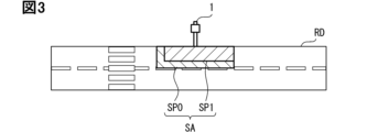
- FIG. 3 is a diagram illustrating an example of a parking availability map.
- FIG. 3 is a diagram illustrating an example of a parking availability map.
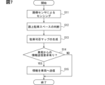
- the flowchart which shows the example of the process by a roadside machine.
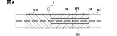
- FIG. 3 is a diagram illustrating an example of a parking availability map.
- FIG. 1 is a diagram showing a schematic configuration of a reservation system.
- the figure which shows the example of a display by CID. A diagram for explaining automatic parking using communication. Flowchart illustrating an example of processing by a vehicle.
- the roadside machine 1 of the first embodiment is a parking assistance device installed on the roadside.
- the roadside machine 1 provides a local parking support service in the sensing area SA, which will be described later.
- the roadside unit 1 is sometimes called an RSU (Road Side Unit).
- the roadside machine 1 may constitute a part of transportation infrastructure.
- the roadside device 1 can also be called a V2I communication device that communicates with the vehicle 20.
- the roadside device 1 may be configured to be able to perform V2I (Vehicle-to-Infrastructure) communication between the vehicle 20 and the roadside device 1.
- V2I communication is also sometimes called road-to-vehicle communication.
- As the architecture of V2X communication including V2I communication an architecture defined in ISO21217, ETSI TS 102 940-943, IEEE 1609, etc. may be adopted.
- the roadside device 1 can also be an element constituting an ITS (Intelligent Transport System).
- the roadside device 1 includes a processing device 2, a communication circuit 3, a roadside sensor 4, a map database (hereinafter referred to as map DB) 5, and the like.
- the processing device 2 is mainly configured with a computer, for example.
- a computer constituting the processing device 2 may include at least one memory 2a and at least one processor 2b.
- the memory 2a is at least one type of non-transitional physical storage medium, such as a semiconductor memory, a magnetic medium, an optical medium, etc., that non-temporarily stores programs, data, etc. that can be read by the processor 2b. good.
- a rewritable volatile storage medium such as a RAM (Random Access Memory) may be provided.
- the processor 2b includes, as a core, at least one type of, for example, a CPU (Central Processing Unit), a GPU (Graphics Processing Unit), and a RISC (Reduced Instruction Set Computer)-CPU.
- the communication circuit 3 is configured to be capable of V2I communication with the vehicle 20.
- the communication circuit 3 has a configuration including a modulation circuit, a demodulation circuit, and an amplification circuit.
- the communication circuit 3 modulates and amplifies the message provided from the processing device 2 and transmits it from the antenna 3a. Furthermore, the communication circuit 3 demodulates and amplifies a message received through the antenna 3a and provides the demodulated and amplified message to the processing device 2.
- the frequency used for communication may be, for example, a 5 GHz band or a 700 MHz band.
- the roadside sensor 4 is configured to be able to sense the sensing area SA of the road RD around the roadside device 1.
- the roadside sensor 4 is fixedly installed on the road RD.
- the roadside sensor 4 may be held at the tip of a pole or the like, a building, or the like in order to realize a wide sensing area SA or to suppress the occurrence of blind spots due to obstacles.
- the sensing area SA is set in advance to include the road RD.
- the roadside sensor 4 is, for example, a camera, LiDAR (Light Detection and Ranging/Laser Imaging Detection and Ranging), imaging radar, or the like.
- the roadside sensor 4 may have a configuration in which a plurality of types of sensors are combined.
- the map DB 5 is mainly composed of a storage medium that non-temporarily stores computer-readable data.
- the storage medium may be at least one type of non-transitive physical storage medium, such as semiconductor memory, magnetic media, optical media, and the like.
- the map DB5 stores a map related to the road area including the sensing area SA.
- the map may include a parking map in which parking spaces SP1 and non-parking spaces SP0 are stored in a distinguishable manner.
- the map stored in the map DB 5 may be a map that can be updated by the processing device 2 and includes dynamic information.
- the vehicle 20 may be a vehicle capable of realizing automatic driving at an automatic driving level 3 or higher as defined in SAE J3016. Further, the vehicle 20 may be a vehicle capable of realizing autonomous driving level 1 or 2 driving.
- the vehicle 20 capable of achieving autonomous driving level 1 or 2 may be a vehicle in which an in-vehicle system can perform driving support to support the driver's driving.
- Automated driving or driving assistance may include one or both of automatic parking, in which an in-vehicle system automatically performs parking, and parking assistance, in which an in-vehicle system assists the driver with parking.
- the vehicle 20 may correspond to one or both of the parking request vehicle and the information providing vehicle.
- An in-vehicle system is sometimes called an OBU (On-Board Unit). Furthermore, an in-vehicle system that performs automatic driving is sometimes called an automatic driving system.
- An in-vehicle system capable of V2X (vehicle-to-everything) communication with the roadside device 1 and another vehicle can also be called a V2X communication device.
- the vehicle 20 includes a processing device 21, a communication circuit 22, an on-vehicle sensor 23, a driving actuator 24, a display device 25, an operation input device 26, and the like.
- the processing device 21 and the communication circuit 22 may be included in the in-vehicle system.
- At least one of the on-vehicle sensor 23, the driving actuator 24, the display device 25, and the operation input device 26 may be further included in the on-vehicle system.
- the processing device 21 is, for example, an in-vehicle device mainly composed of a computer.
- a computer constituting the processing device 21 may include at least one memory 21a and at least one processor 21b.
- the memory 21a is at least one type of non-transitional physical storage medium, such as a semiconductor memory, a magnetic medium, and an optical medium, for non-temporarily storing programs, data, etc. that can be read by the processor 21b. good.
- a rewritable volatile storage medium such as a RAM (Random Access Memory) may be provided as the memory 21a.
- the processor 21b includes, as a core, at least one type of, for example, a CPU (Central Processing Unit), a GPU (Graphics Processing Unit), and a RISC (Reduced Instruction Set Computer)-CPU.
- the communication circuit 22 is configured to be capable of V2I communication with the roadside device 1. Furthermore, the communication circuit 22 may be configured to be capable of V2V (vehicle-to-vehicle) communication with other vehicles.
- the communication circuit 22 has a configuration including a modulation circuit, a demodulation circuit, and an amplification circuit.
- the communication circuit 22 modulates and amplifies the message provided from the processing device 21 and transmits it from the antenna 22a. Furthermore, the communication circuit 22 demodulates and amplifies a message received through the antenna 22a and provides the demodulated and amplified message to the processing device 21.
- the frequency used for communication may be, for example, a 5 GHz band or a 700 MHz band.
- the on-vehicle sensor 23 is configured to be able to sense the sensing area SA around the vehicle 20.
- the on-vehicle sensor 23 is, for example, a camera, LiDAR, laser radar, millimeter wave radar, ultrasonic sonar, imaging radar, or the like.
- the on-vehicle sensor 23 may be mounted on the vehicle 20 by combining a plurality of sensors or a plurality of types of sensors in order to sense the front, side, and rear of the vehicle 20.
- the driving actuator 24 is an actuator for driving the vehicle 20.
- a plurality of driving actuators 24 of different types may be provided in the vehicle 20.
- the driving type driving actuator 24 is, for example, a power train including at least one type of an internal combustion engine, an electric motor, and the like.
- the braking type driving actuator 24 is, for example, a brake actuator.
- the steering type driving actuator 24 is, for example, a steering wheel.
- the operation actuator 24 is configured to be controllable by the processing device 21, for example.
- the display device 25 displays information for the occupants of the vehicle 20, including the driver.
- the display device 25 is, for example, a graphic meter, a combination meter, a car navigation system, a CID (Center Information Display), or a HUD (Head-Up Display).
- the display device 25 may include a display capable of displaying images.
- the operation input device 26 accepts operations by occupants of the vehicle 20, including the driver.
- the operation input device 26 may be an accelerator pedal, a brake pedal, or a steering wheel for operating the driving actuator 24 during manual driving.
- the operation input device 26 may be a switch, a lever, a touch panel, etc. for transmitting the occupant's intention to the processing device 21.
- the touch panel may be configured to be integrated with the display.
- the display device 25 and the operation input device 26 may be collectively referred to as an HMI (Human Machine Interface).
- the processing device 2 of the roadside device 1 is configured to include a space determination section 11, a map generation section 12, and a space information transmission section 13 as functional blocks implemented by a processor 2b that executes a program.
- the space determination unit 11 determines the on-street parking space in the sensing area SA of the roadside sensor 4. The space determination unit 11 determines whether parking is allowed or not in the space that constitutes the sensing area SA. The space determining unit 11 determines that an area where parking is prohibited according to the Road Traffic Act is a non-parking space SP0 without exception, and designates it as a non-parking space SP0.
- the space determination unit 11 acquires the sensing results of the sensing area SA from the roadside sensor 4.
- the space determination unit 11 processes the sensing results and recognizes objects in the sensing area SA. For example, when an image is obtained as a sensing result, it is possible to recognize the object, including its type, using semantic segmentation. For example, if a reflected signal of a pulse emitted by LiDAR is obtained as a sensing result, recognition including the distance of the object is possible using a technique such as TOF (Time Of Flight).
- TOF Time Of Flight
- the space determination unit 11 designates an area in the sensing area SA in which it is determined that a static object is present through object recognition as a parking prohibited space SP0.
- a dynamic object for example, a vehicle running on the road
- the area where the dynamic object is recognized does not need to be designated as the non-parking space SP0.
- Whether an object is dynamic or static can be determined by, for example, whether the object is continuously recognized at the same position in time-series data of sensing results.
- the space determining unit 11 may determine whether parking is possible for each segment of the sensing area SA.
- the segment to be determined may be one in which the sensing area SA is virtually divided in advance.
- the size of the segment may be set to comply with the official format in V2X communication.
- the size of the segment may be set as appropriate based on the viewpoint of calculation processing load, communication load, reliability of the parking space output as a calculation result, etc.
- the sensing area SA may be divided into segments with a size equivalent to one standard vehicle.
- the sensing area SA may be divided into matrix-like segments each having a size of, for example, 1 m square. In this way, when the segments are set relatively large, the computational processing load and communication load due to increased data amount can be reduced. On the other hand, if even a portion of the segment overlaps with an area where parking is prohibited under the Road Traffic Act, the entire segment must be designated as a parking prohibited space SP0.
- the sensing area SA may be divided into segments as fine as about 30 cm square. In this way, when the segments are set relatively small, spaces can be presented with higher precision, such as by presenting a road sign as the boundary between the parking space SP1 and the non-parking space SP0.
- the map generation unit 12 generates a parking availability map in which the road map information stored in the map DB 5 in advance and the determination result by the space determination unit 11 are associated.
- the parking availability map is a dynamic map that is updated every time the space determination unit 11 makes a determination.
- the map generation unit 12 causes the map DB 5 to store a parking availability map based on the latest information.
- FIG. 3 visualizes and explains an example of a parking availability map.
- a parking space SP1 and a non-parking space SP0 are associated and overlapped.
- the map generation unit 12 may add information regarding the cost of on-street parking to each available parking space SP1, as shown in FIG.
- the cost may be calculated by the space determining section 11 or the map generating section 12. If the cost is mapped, a numerical value indicating the cost may be associated with each parking space SP1.
- the costs may be classified into a plurality of classifications, such as low-cost spaces and high-cost spaces, and the classifications may be associated with each parking space SP1. In the example of FIG. 4, a low performance space SP11 corresponding to a large cost and a high performance space SP12 corresponding to a small cost are set as the plurality of classifications.
- the cost may be calculated based on parking performance.
- the parking record may be based on the number of times on-street parking was actually performed for the space.
- the parking record may be obtained by the roadside device 1 accumulating the sensing results of the roadside sensor 4.
- the parking record may be obtained from data provided by V2I communication from the vehicle 20 parked in the sensing area SA.
- the cost may be a cost imposed on a vehicle traveling on the road RD. That is, the cost required for a vehicle traveling on the road RD to avoid a vehicle parked on the road may be calculated. For example, the amount of change in the trajectory of a running vehicle to avoid a vehicle parked on the road may be calculated as the cost. For example, the cost may be calculated as the amount of time it takes for a running vehicle to avoid a vehicle parked on the street.
- the map generation unit 12 may generate a parking availability map with the same granularity as the segment.
- the map generation unit 12 may integrate the plurality of segments into coarser-grained segments and then generate the parking permission map.
- the map generation unit 12 may generate both a parking permission map expressed in segments corresponding to the first message format and a parking permission map expressed in segments corresponding to the second message format. . In this way, information can be quickly provided to vehicles 20 that comply with each format.
- the information on the judgment result by the space judgment unit 11 and the parking availability map generated by the map generation unit 12 and stored in the map DB 5 correspond to parking area data indicating the parking area.
- the space information transmitter 13 transmits information regarding the on-street parking space by V2I communication using the communication circuit 3 in accordance with a request from a vehicle that approaches the sensing area SA and desires to park on the street in the sensing area SA. do.
- the information regarding on-street parking spaces may be substantially the parking area data itself, may be an excerpt of the parking area data, or may be a processed version of the parking area data. good.
- the information regarding on-street parking spaces may be the parking availability map itself, or may be information extracted from the parking availability map.
- the information regarding on-street parking spaces may simply be information indicating whether or not a parking space SP1 exists in the sensing area SA.
- Information regarding on-street parking spaces may be transmitted in a predetermined message format.
- the processing device 21 of the vehicle 20 (particularly the vehicle desired to park) is configured to include a transmission request section 31, a space display section 32, and an automatic parking section 33 as functional blocks realized by a processor 21b that executes a program.
- the transmission request unit 31 determines whether the destination of the vehicle 20 is the sensing area SA of the roadside device 1 or around the sensing area SA, and whether or not the vehicle 20 is planning to park on the road around the destination.
- the destination may be, for example, a destination set by the occupant in the navigation system of the vehicle 20.
- the destination may be a destination set by the occupant for autonomous driving.
- the navigation system is a system that shows the driver the route to the destination of the vehicle 20.
- the transmission requesting unit 31 requests the roadside device 1 corresponding to the sensing area SA to provide information regarding the on-street parking space.
- Approaching the sensing area SA here may mean approaching a distance at which V2I communication (for example, direct communication using a single-hop method) with the communication circuit 3 of the roadside device 1 is possible.
- the space display unit 32 generates display content to be displayed on the display device 25 based on information regarding on-street parking spaces.
- the display content may be content that is displayed as a real image on the CID as the display device 25.
- the display content may be content DC1 displayed on the CID screen.
- the display content may be content DC1 that is displayed in a bird's-eye view of the sensing area SA on the road RD.
- the display content may be in a form in which a parking space image showing a parking space and an image showing a non-parking space are superimposed on an image showing the road RD.
- the plurality of available parking spaces may be selectively selectable by receiving an operation by the occupant on the operation input device 26 (for example, a touch panel integrated with the screen).
- An automatic parking unit 33 which will be described later, will perform automatic parking in the selected parking space SP1.
- the display content may be content DC2 that is displayed as a virtual image on the HUD as the display device 25.
- the display content may be AR display content used for augmented reality (AR) display superimposed on the environment outside the vehicle.
- AR augmented reality
- the display content may be configured to be superimposed on the road surface outside the vehicle.
- the display content may include an image showing a parking space that is superimposed on a parking space on the road surface, and an image showing a non-parking space that is superimposed on a non-parking space.
- the plurality of parking spaces SP1 may be selectively selectable by receiving an operation of the operation input device 26 by the occupant.
- the operation input device 26 in this case may be, for example, a steering wheel switch.
- the automatic parking unit 33 automatically parks the vehicle in the parking space SP1 selected by the occupant.
- the automatic parking unit 33 calculates a travel trajectory from the current position of the vehicle 20 to the parking space SP1 selected by the occupant.
- the travel trajectory includes a trajectory for performing parallel parking, including a turnaround.
- the automatic parking unit 33 determines the operation of the driving actuator 24 to realize the calculated travel trajectory, and controls the driving actuator 24.
- the vehicle 20 is thus parked on the street by the on-vehicle system.
- steps S11 to S15 are started at predetermined time intervals or based on a predetermined trigger.
- the roadside sensor 4 performs sensing of the sensing area SA. After processing in S11, the process advances to S12.
- the space determination unit 11 executes on-street parking space determination for the sensing area SA. After processing in S12, the process advances to S13.
- the map generation unit 12 generates a parking permission map for the sensing area SA based on the determination by the space determination unit 11. After processing in S13, the process advances to S14.
- the space information transmission unit 13 determines whether there is an information transmission request from the vehicle 20 approaching the sensing area SA. If Yes, proceed to S15. If No, the series of processing ends.
- the space information transmitting unit 13 transmits information regarding on-street parking spaces to the vehicle 20 approaching the sensing area SA. This completes the series of processing.
- the roadside device 1 can support the vehicle 20 to park smoothly on the road. In this way, a parking support service can be realized.
- the parking area data includes a parking permission map indicating the parking spaces SP1 and the non-parking spaces SP0. Since the map clearly indicates the parking space SP1 and the non-parking space SP0, the vehicle 20 can easily determine where to park on the street.
- the cost related to on-street parking is calculated for the parking space SP1, and the parking space SP1 is further classified into a plurality of categories according to the cost.
- the vehicle 20 can easily determine the optimal position for street parking in the available parking space SP1.
- the information regarding the on-street parking space includes data including a plurality of segments obtained by dividing the sensing area SA into a matrix, and information on whether parking is allowed or not allowed, added to each of the plurality of segments. including. Since data is configured using segments, information regarding on-street parking spaces can be exchanged between devices in a general-purpose manner.
- the second embodiment is a modification of the first embodiment.
- the second embodiment will be described focusing on the differences from the first embodiment.
- the roadside device 1 of the second embodiment provides a parking support service not only in the sensing area SA but also in an area including the sensing extended area ESA.
- the sensing expansion area ESA is an area that is sensed by the on-vehicle sensor 23 of the information providing vehicle 20a that provides information on sensing results to the roadside device 1, and is an area excluding the sensing area SA of the roadside sensor 4.
- the information providing vehicle 20a may be a different vehicle from the parking desired vehicle 20b, or may be the same vehicle.
- the roadside device 1 may collect sensing results from a plurality of information providing vehicles 20a.
- the processing device 21 of the vehicle 20 (particularly the information providing vehicle 20a) is configured to include a sensing result transmitter 34 as a functional block implemented by a processor 21b that executes a program.
- the sensing result transmitter 34 acquires sensing results from the on-vehicle sensor 23.
- the sensing result transmitter 34 transmits information regarding the sensing result to the roadside device 1. decide.
- the sensing result transmitter 34 generates a message containing information regarding the sensing result based on the sensing result.
- This message may be, for example, a Collective Perception Message (CPM).
- CPM Collective Perception Message
- the space determination unit 11 determines the on-street parking space in the sensing area SA based on the sensing results obtained from the roadside sensor 4. Furthermore, the space determination unit 11 in the roadside device 1 determines the on-street parking space in the sensing extension area ESA based on the information regarding the sensing results received from the information providing vehicle 20a.
- the map generation unit 12 generates a parking availability map (see FIG. 9) for the sensing area SA and the sensing expansion area ESA based on the determination result by the space determination unit 11. Based on such a parking availability map, information regarding on-street parking spaces is provided to the vehicle 20b desiring parking.
- the processing device 2 of the roadside device 1 collects the sensing result from the communication target sensing the sensing extended area ESA outside the sensing area SA, which includes the vehicle 20a different from the desired parking vehicle 20b. information regarding the communication is received through the communication circuit 3. Then, the processing device 2 expands and generates the dynamic parking available area data to include information on the sensing expansion area ESA.
- the third embodiment is a modification of the first embodiment.
- the third embodiment will be described focusing on the differences from the first embodiment.
- a plurality of roadside machines 1 shown in the first embodiment which are installed at locations separated from each other, are connected to, for example, the Internet. It is configured to be able to communicate with the cloud server 41.
- each roadside machine 1 provides on-street parking space reservation service to the vehicle 20 by cooperating with the cloud server 41.
- the plurality of roadside machines 1 and cloud server 41 constitute a reservation system 40.
- the cloud server 41 is a remote center that aggregates and manages reservation information.
- the cloud server 41 is connected to the Internet, for example, so that it can communicate with a plurality of roadside machines 1 in a wide area and vehicles 20 in a wide area. Communication between the cloud server 41 and the vehicle 20 may be referred to as V2N (Vehicle-to-Network) communication or V2C (Vehicle-to-Cloud) communication.
- V2N Vehicle-to-Network
- V2C Vehicle-to-Cloud
- the cloud server 41 collects local data from each roadside machine 1.
- the cloud server 41 provides each vehicle 20 with integrated data that integrates local data.
- the cloud server 41 accepts reservations from each vehicle 20.
- the cloud server 41 provides each roadside machine 1 with reservation information for each vehicle 20.
- the cloud server 41 refers to a server on a network realized by cloud computing.
- the cloud server 41 includes at least one processing device 42 and a map DB 43.
- the cloud server 41 may be realized by one processing device 42, or may be realized by a plurality of processing devices 42 that cooperate with each other.
- the plurality of processing devices 42 may be located at remote locations separated from each other.
- the processing device 42 may be realized mainly by a computer.
- the computer constituting the processing device 42 may have at least one memory 42a and at least one processor 42b.
- the memory 42a is at least one type of non-transitional physical storage medium, such as a semiconductor memory, a magnetic medium, an optical medium, etc., that non-temporarily stores programs, data, etc. that can be read by the processor 42b. good.
- a rewritable volatile storage medium such as a RAM (Random Access Memory) may be provided as the memory 42a.
- the processor 42b includes, as a core, at least one type of, for example, a CPU (Central Processing Unit), a GPU (Graphics Processing Unit), and a RISC (Reduced Instruction Set Computer)-CPU.
- the map DB 43 is mainly composed of a storage medium that non-temporarily stores computer-readable data.
- the storage medium may be at least one type of non-transitive physical storage medium, such as semiconductor memory, magnetic media, optical media, and the like.
- the map DB 43 stores a wide-area parking availability map that is a collection of local parking availability maps stored in the map DB 5 of each roadside device 1. For this reason, the storage capacity of the map DB 5 of the cloud server 41 is preferably larger than the storage capacity of the map DB 5 of each roadside machine 1.
- the map DB 43 may further store reservation information associated with each space of the parking availability map.
- the reservation information may include information on the vehicle 20 to be reserved (for example, vehicle ID, information regarding the size of the vehicle body), reservation time, and the like.
- the processing device 2 of the roadside device 1 is configured to include a space determination section 11, a map generation section 12, and a local data transmission section 14 as functional blocks implemented by a processor 2b that executes a program.
- the space determination unit 11 reflects the reservation information provided from the cloud server 41 in determining whether parking is available in the on-street parking space. Specifically, the space determination unit 11 designates the space in which parking has been reserved as the non-parking space SP0.
- the map generation unit 12 updates the parking availability map of the sensing area SA to the latest state, similarly to the first embodiment. This local parking availability map is stored in the map DB5.
- the local data transmitter 14 transmits local data, that is, information regarding local on-street parking spaces, to the cloud server 41. Specifically, the local data transmitter 14 transmits the latest parking availability map stored in the map DB 5 to the cloud server 41. According to the configuration in which the parking availability map is transmitted, the amount of data to be transmitted can be made smaller than when the sensing results from the roadside sensor 4 are transmitted to the cloud server 41, and the processing load on the cloud server 41 can be reduced. can.
- the processing device 42 of the cloud server 41 has a configuration including a map integration section 51, an integrated data transmission section 52, a reservation reception section 53, and a reservation information transmission section 54 as functional blocks realized by a processor 42b that executes a program.
- the map integration unit 51 integrates local parking availability maps provided from each roadside machine 1.
- the integrated map (hereinafter referred to as integrated map) is a wide-area parking availability map.
- the roadside machines 1 that are adjacent to each other are arranged such that their sensing areas SA are not separated from each other, for example, the ends of the sensing areas SA overlap.
- the integrated map can cover on-street parking spaces in a contiguous, wide area.
- the map integration unit 51 stores an integrated map based on the latest information in the map DB 43.
- the integrated data transmitter 52 transmits integrated data to the vehicle 20.
- the integrated data is, for example, the latest integrated map stored in the map DB 43.
- the data transmitted by the cloud server 41 may be excerpt data of information around the destination from the integrated map. .
- the reservation reception unit 53 accepts reservations from the vehicle 20.
- the reservation accepting unit 53 may accept a space directly designated by the vehicle 20 as a reserved space.
- the reservation reception unit 53 may receive a designation of a desired parking area from the vehicle 20, and select an optimal reservation space from the desired parking area.
- the reservation information transmitting unit 54 transmits reservation information to the roadside machine 1 in charge of the reserved space in response to acceptance of the reservation.
- the reservation information transmitter 54 may request that the roadside device 1 respond that the reservation has been processed normally.
- the reservation reception unit 53 may reflect the reservation information in the map DB 5 of the roadside device 1. Further, the reservation information transmitter 54 may notify the vehicle 20 to be reserved that the reservation has been successfully processed.
- the processing device 21 of the vehicle 20 is configured to include a data request section 35, a space display section 32, and a reservation request section 36 as functional blocks realized by a processor 21b that executes a program.
- the data requesting unit 35 requests the cloud server 41 to transmit data for determining the on-street parking space to reserve.
- the trigger for the request by the data requesting unit 35 may be, for example, an operation of the operation input device 26 by the driver of the vehicle 20, that is, an expression of intention to make a reservation.
- the automatic driving system may provide a data request trigger without requiring the driver to express his/her intention.
- the reservation should be made when the vehicle 20 is far away from the destination, not after the vehicle 20 approaches the sensing area SA around the destination as in the first embodiment. Then, the reservation function of the reservation system 40 can be utilized more effectively.
- the space display unit 32 When data is provided from the cloud server 41 in response to a data request, the space display unit 32 causes the display device 25 to display information based on the data.
- the space display unit 32 When the provided data is an integrated map, the space display unit 32 generates display content similar to the first embodiment. However, as shown in FIG. 13, the display content of the third embodiment may include a relatively wide parking availability map that includes the destination.
- the vehicle 20 is immediately parked in the selected parking space SP1 among the available parking spaces SP1 displayed by the display device 25, but in the third embodiment, the vehicle 20 is immediately parked in the selected parking space SP1. Parking space SP1 will be reserved.
- the reservation requesting unit 36 requests the cloud server 41 to reserve the parking space SP1.
- the cloud server 41 integrates the data collected from the plurality of roadside machines 1, transmits it to the vehicle 20, and shares the reservation request for the vehicle 20 with the roadside machine 1.
- the vehicle 20 that wishes to park can secure a parking space on the road. In this way, the quality of parking assistance service can be improved.
- the fourth embodiment is a modification of the first embodiment or the third embodiment.
- the fourth embodiment will be described with a focus on the points that are different from the first embodiment or the third embodiment.
- the parking availability map generated by the map generation unit 12 includes information on parking results.
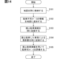
- an example of a processing method for generating a parking availability map including parking record information will be described in detail using the flowchart of FIG. 14.
- the map generation unit 12 stores a road map in which road information is stored in the map DB5.
- the road information may be downloaded from a road map server that distributes road maps, or may be downloaded from the cloud server 41 of the reservation system 40 as described in the third embodiment. It is preferable that the map generation unit 12 periodically downloads road information and updates the road information in the map DB 5 to the latest information. After processing in S101, the process advances to S102.
- the map generation unit 12 adds the area where parking is prohibited according to the Road Traffic Act to the road map stored in the map DB 5 as information on the non-parking space SP0. After processing in S102, the process advances to S103.
- the map generation unit 12 adds or updates information on the on-street parking record to the on-street parking space and records it in the map DB5.
- the information on the on-street parking record may be the cumulative number of on-street parking for the target space.
- the information on on-street parking performance may be the number of on-street parkings for a predetermined period, in other words, the frequency of on-street parking.
- the space judgment unit 11 or the map generation unit 12 calculates the cost required for the avoidance when the vehicle traveling on the road RD avoids the vehicle 20 parked on the road and detours around the road.
- the map generation unit 12 records information on the cost required for avoidance in the map DB 5 as an adverse effect caused by the vehicle 20 parked on the road. Information regarding adverse effects may be included in information on on-street parking performance. After processing in S104, the process moves to S105.
- the space determining unit 11 or the map generating unit 12 evaluates the available parking space SP1 using the information on the on-street parking record recorded in the map DB5.
- the evaluation here may be to calculate the cost of on-street parking for the parking space SP1.
- the series of processing ends at S105.
- the fifth embodiment is a modification of the fourth embodiment.
- the fifth embodiment will be described with a focus on differences from the fourth embodiment.
- the roadside device 1 generates a map also for the sensing extended area ESA by receiving information from the information providing vehicle 20a as in the second embodiment.
- the processing device 21 of the vehicle 20 (especially the vehicle 20b desired to park) causes the destination surrounding information search section 37, the parking request section 38, the parking position determination section 39, and the automatic parking section 33 to execute the program.
- This configuration is included as a functional block realized by the processor 21b.
- the destination surrounding information search unit 37 searches for information around the destination.
- the information around the destination includes information on parking lots around the destination.
- the area around the destination may be within walking distance of the destination, and is preset, for example, within a range of 500 m, 1 km, etc. from the destination.
- the destination surrounding information search unit 37 further determines whether there is a vacant parking lot near the destination.
- the parking request unit 38 requests on-street parking at the roadside machine 1 near the destination. Request information about your space.
- This parking request may be a direct request to the roadside device 1 if the vehicle 20 has already approached the roadside device 1 within a communicable distance.
- This parking request may be replaced with a reservation request to the reservation system 40, that is, a request to the cloud server 41, if the vehicle 20 is far from the destination.
- the parking position determining unit 39 determines the parking position of the vehicle 20. Specifically, when information regarding on-street parking spaces is provided from the roadside device 1, the parking position determination unit 39 selects the optimal parking space SP1 based on on-street parking performance information, the size of the vehicle 20, etc. Select a suitable parking location. This optimal parking position is proposed to the driver. If the proposal is accepted by the driver, the parking position determining unit 39 starts guiding the driver to the parking position.
- the parking position determination unit 39 causes the display device 25 to display a list of available parking spaces SP1, and accepts a parking position selection operation from the driver.
- the parking position determining unit 39 starts guiding the driver to the parking position.
- the suggestion or list display to the driver may be, for example, a display in which an image showing the destination or an image showing the optimal parking position is superimposed on a parking availability map as shown in FIG.
- the start of guidance to the parking position may be the start of on-street parking assistance if the vehicle 20 has already approached the roadside device 1 within a communicable distance.
- On-street parking support is a concept that includes both automatic parking that does not require the driver to drive, and auxiliary support for driving behavior by the driver.
- the start of guidance to the parking position may be the start of route guidance to the parking position by the navigation system when the vehicle 20 is far from the destination. At the same time, a reservation may be made to the reservation system 40 for a space corresponding to the parking position.
- the automatic parking unit 33 performs automatic parking at the parking position determined by the parking position determining unit 39.
- the sensing results of the roadside sensor 4 provided from the roadside device 1 can be utilized for automatic parking.
- the automatic parking unit 33 optimizes the actual parking position to a position that is less likely to be a nuisance to traveling vehicles.
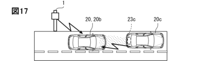
- the automatic parking unit 33 may communicate with another vehicle 20c parked on the road adjacent to the parking position, as shown in FIG. 17.
- the automatic parking unit 33 may receive the sensing result of the on-vehicle sensor 23c of the other vehicle 20c, and use the sensing result to optimize the actual parking position. By doing so, it is possible to more safely minimize the distance from the other vehicle 20c.
- the processing device 2 of the roadside device 1 includes a parking support unit 15 implemented by a processor 2b that executes a program. This is a configuration that is included as a functional block.
- the parking support unit 15 provides the sensing result of the roadside sensor 4 to the vehicle 20 when the parking position is included in the sensing area SA of the roadside device 1. Thereby, as described above, the parking position by the automatic parking section 33 is optimized.
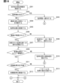
- the destination surrounding information search unit 37 searches for surrounding information about the destination. After processing in S201, the process advances to S202.
- the destination surrounding information search unit 37 determines whether or not there is a vacant parking lot near the destination that can be used. If Yes, the process advances to S203. If No, the process advances to S204.
- the parking position determination unit 39 determines the optimal on-street parking space. After processing in S204, the process advances to S205.
- the parking position determination unit 39 proposes an optimal parking position to the driver. Specifically, the parking position determination unit 39 causes the display device 25 to display the parking position. After processing in S205, the process advances to S206.
- the parking position determining unit 39 determines whether the proposal has been accepted by the driver. If Yes, the process advances to S207. If No, the process advances to S208.
- the parking position determination unit 39 starts guiding the user to the approved parking position. After the processing in S207, the process proceeds to S209.
- the parking position determining unit 39 causes the display device 25 to display a list of available parking spaces SP1, and allows the driver to select a parking position. After the selection, the parking position determination unit 39 proceeds to S209 after processing S208.
- the parking position determination unit 39 determines whether the determined parking position is within the sensing area SA of the roadside device 1. In the case of Yes, parking assistance by the roadside device 1 is requested, and the process advances to S211. If No, the process advances to S210.
- the parking position determination unit 39 displays the determined parking position on the display device 25.
- the determined parking position may be displayed, for example, so as to be superimposed on a road map of a navigation system.
- the series of processing ends at S210.
- the parking position determining unit 39 determines whether automatic parking is possible in on-street parking. If Yes, the process advances to S212. If No, the process advances to S213.
- the automatic parking unit 33 uses the sensing results transmitted from the roadside machine 1 to perform automatic parking.
- the series of processing ends at S212.
- the driver's parking behavior is supported using the display on the display device 25.
- the sensing result transmitted from the roadside device 1 or the object recognition information analyzed using the sensing result is displayed on the display device 25.
- the series of processing ends at S213.
- the fifth embodiment described above it is possible to support the smooth on-road parking of the vehicle 20b desired to park using the sensing results of the roadside device 1. In this way, the vehicle 20b wishing to park can effectively enjoy the parking support service.
- approaching the sensing area SA is V2I communication between the communication circuit 22 of the vehicle 20 and the communication circuit 3 of the roadside device 1, and the distance is such that direct communication in a multi-hop method is possible. It may mean approaching.
- the processing device 21 on the vehicle 20 side may calculate the cost of on-street parking.
- the processing device 21 may acquire or analyze information on the driver's driving proficiency level and reflect the proficiency level in the cost.
- the roadside machine 1 communicates with another roadside machine, acquires the sensing result of the sensing area of the roadside sensor of the other roadside machine, and generates a parking permission map in the sensing extended area ESA based on this. You may.
- control unit and its method described in the present disclosure may be implemented by a dedicated computer comprising a processor programmed to perform one or more functions embodied by a computer program.
- the apparatus and techniques described in this disclosure may be implemented with dedicated hardware logic circuits.
- the apparatus and techniques described in this disclosure may be implemented by one or more special purpose computers configured by a combination of a processor executing a computer program and one or more hardware logic circuits.
- the computer program may also be stored as instructions executed by a computer on a computer-readable non-transitory tangible storage medium.
- a roadside machine that is installed on the roadside and supports parking of a vehicle (20, 20b) on the road, a roadside sensor (4) that senses a sensing area (SA) of the road (RD) around the installation location; at least one processor (2b) generating dynamic parking available area data in the sensing area; a storage medium (5) that stores the parking area data;
- the at least one processor includes: Information regarding the sensing result is transmitted from a communication target sensing a sensing extended area (ESA) outside the sensing area, including at least one of a vehicle (20b) different from the vehicle desired to park and another roadside device. receiving through a communication circuit;
- ESA sensing extended area
- the roadside machine according to technical idea 1, further configured to expand and generate the dynamic parking available area data to include information on the sensing expansion area.
- the roadside machine (Technical thought 3) The roadside machine according to technical idea 1 or 2, wherein the parking area data includes a parking permission map indicating a parking space (SP1) and a non-parking space (SP0).
- SP1 parking space
- SP0 non-parking space
- the at least one processor includes: According to technical idea 3, the vehicle is configured to further calculate a cost related to on-street parking for the available parking space, and classify the available parking space into a plurality of categories according to the cost. Roadside machine.
- the at least one processor includes: The roadside machine according to technical idea 3 or 4, further configured to add information on on-street parking performance to the parking availability map when on-street parking is done in the sensing area.
- the information regarding the on-street parking space includes data including a plurality of segments obtained by dividing the sensing area into a matrix, and information on whether parking is allowed or not allowed, added to each of the plurality of segments. 5.
- the roadside machine according to any one of 5.
Landscapes
- Physics & Mathematics (AREA)
- General Physics & Mathematics (AREA)
- Engineering & Computer Science (AREA)
- Radar, Positioning & Navigation (AREA)
- Remote Sensing (AREA)
- Automation & Control Theory (AREA)
- Traffic Control Systems (AREA)
Abstract
路側機(1)は、路側に設置され、車両(20)の路上駐車を支援する。路側機(1)は、設置場所周辺の道路(RD)のうちのセンシング領域(SA)をセンシングする路側センサ(4)と、センシング領域(SA)での動的な駐車可能領域データを生成するプロセッサ(2b)と、駐車可能領域データを記憶するマップDB(5)と、車両(20)とV2I通信する通信回路(3)と、を備える。プロセッサ(2b)は、センシング領域(SA)に接近し、センシング領域(SA)への路上駐車を希望する車両(20)としての駐車希望車両に対して、駐車可能領域データに基づく路上駐車スペースに関する情報を、通信回路(3)に送信させることを、実行するように構成される。
Description
この出願は、2022年8月30日に日本に出願された特許出願第2022-137297号を基礎としており、基礎の出願の内容を、全体的に、参照により援用している。
この明細書による開示は、路上駐車を支援する技術に関する。
特許文献1には、サーバ又はクラウドベースの駐車容易化システムが開示されている。駐車容易化システムは、複数のセンサからセンサ情報を集め、可能な駐車スペースを識別し、駐車スペースマップを生成する。
しかしながら、特許文献1のようにあらゆるセンサ情報をサーバ又はクラウド等のセンタに集約するシステムでは、センサ情報が膨大となる。このため、センサ情報の集約のための通信負荷、センサ情報から駐車スペースを識別するための処理負荷への影響が懸念され得る。
この明細書の開示による目的のひとつは、駐車支援サービスをローカルベースで実現する路側機を提供することにある。また、目的の他のひとつは、この駐車支援サービスと連携した予約システム及び車載装置を提供することにある。
ここに開示された態様のひとつは、路側に設置され、車両の路上駐車を支援する路側機であって、
設置場所周辺の道路のうちのセンシング領域をセンシングする路側センサと、
センシング領域での動的な駐車可能領域データを生成する少なくとも1つのプロセッサと、
駐車可能領域データを記憶する記憶媒体と、
車両とV2I通信する通信回路と、を備え、
少なくとも1つのプロセッサは、
センシング領域に接近し、センシング領域への路上駐車を希望する車両としての駐車希望車両に対して、駐車可能領域データに基づく路上駐車スペースに関する情報を、通信回路に送信させることを、実行するように構成される。
設置場所周辺の道路のうちのセンシング領域をセンシングする路側センサと、
センシング領域での動的な駐車可能領域データを生成する少なくとも1つのプロセッサと、
駐車可能領域データを記憶する記憶媒体と、
車両とV2I通信する通信回路と、を備え、
少なくとも1つのプロセッサは、
センシング領域に接近し、センシング領域への路上駐車を希望する車両としての駐車希望車両に対して、駐車可能領域データに基づく路上駐車スペースに関する情報を、通信回路に送信させることを、実行するように構成される。
このような態様によると、路側機に接近する駐車希望車両に対して、路側センサ4のセンシング結果に基づく路上駐車が可能なスペースに関する情報を、迅速に提供することができる。したがって、駐車希望車両が円滑に路上駐車することを、路側機が支援することができる。このように、駐車支援サービスを実現することができる。
また、ここに開示された態様の他のひとつは、路上駐車の予約を受け付ける予約システムであって、
相互に異なる設置場所に設置され、設置場所周辺の道路のうちのセンシング領域をセンシングし、センシング領域での動的な駐車可能領域データを生成する複数の路側機と、
複数の路側機から駐車可能領域データを収集し、より広域の駐車可能領域データを生成するサーバと、を具備し、
サーバは、
センシング領域への路上駐車を希望する車両としての駐車希望車両に対して、路上駐車スペースに関する情報を送信することと、
路上駐車スペースに関する情報に基づく駐車希望車両からの予約要求に応じて、予約するスペースを管轄する路側機へ、予約情報を送信することと、を実行するように構成される。
相互に異なる設置場所に設置され、設置場所周辺の道路のうちのセンシング領域をセンシングし、センシング領域での動的な駐車可能領域データを生成する複数の路側機と、
複数の路側機から駐車可能領域データを収集し、より広域の駐車可能領域データを生成するサーバと、を具備し、
サーバは、
センシング領域への路上駐車を希望する車両としての駐車希望車両に対して、路上駐車スペースに関する情報を送信することと、
路上駐車スペースに関する情報に基づく駐車希望車両からの予約要求に応じて、予約するスペースを管轄する路側機へ、予約情報を送信することと、を実行するように構成される。
このような態様によると、サーバが複数の路側機から収集したデータを統合し、駐車希望車両へ送信し、当該駐車希望車両の予約要求を路側機と共有する。路側機とサーバとが連携して予約サービスを提供することで、駐車希望車両は、駐車可能な路上を確保しておくことができる。このように、駐車支援サービスの質を高めることができる。
また、ここに開示された態様の他のひとつは、車両に搭載され、車両の路上駐車を支援する処理を実行するために、少なくとも1つのプロセッサを備え、路側に設置され、設置場所周辺の道路のうちのセンシング領域をセンシングする路側センサを備える路側機と通信可能な車載装置であって、
少なくとも1つのプロセッサは、
路側機又は路側機から情報を収集するサーバから、動的な駐車可能領域データを取得することと、
駐車可能領域データに基づき、車両の乗員へ駐車位置を提案することと、
駐車位置が承諾されたことに基づき、駐車位置がセンシング領域内である場合に、路側センサによるセンシング結果を取得し、センシング結果を用いて路上駐車を支援することと、を実行するように構成される。
少なくとも1つのプロセッサは、
路側機又は路側機から情報を収集するサーバから、動的な駐車可能領域データを取得することと、
駐車可能領域データに基づき、車両の乗員へ駐車位置を提案することと、
駐車位置が承諾されたことに基づき、駐車位置がセンシング領域内である場合に、路側センサによるセンシング結果を取得し、センシング結果を用いて路上駐車を支援することと、を実行するように構成される。
このような態様によると、駐車希望車両が円滑に路上駐車することを、路側機のセンシング結果を用いて支援することができる。このように、駐車希望車両が駐車支援サービスを効果的に享受することができる。
なお、請求の範囲等に含まれる括弧内の符号は、後述する実施形態の部分との対応関係を例示的に示すものであって、技術的範囲を限定することを意図するものではない。
以下、複数の実施形態を図面に基づいて説明する。なお、各実施形態において対応する構成要素には同一の符号を付すことにより、重複する説明を省略する場合がある。各実施形態において構成の一部分のみを説明している場合、当該構成の他の部分については、先行して説明した他の実施形態の構成を適用することができる。また、各実施形態の説明において明示している構成の組み合わせばかりではなく、特に組み合わせに支障が生じなければ、明示していなくても複数の実施形態の構成同士を部分的に組み合せることができる。
(第1実施形態)
図1に示すように、第1実施形態の路側機1は、路側に設置されている駐車支援装置である。路側機1は、後述するセンシング領域SAでのローカルな(局所的な)駐車支援サービスを提供する。路側機1は、RSU(Road Side Unit)と呼ばれることがある。路側機1は、交通インフラストラクチャの一部を構成していてもよい。
図1に示すように、第1実施形態の路側機1は、路側に設置されている駐車支援装置である。路側機1は、後述するセンシング領域SAでのローカルな(局所的な)駐車支援サービスを提供する。路側機1は、RSU(Road Side Unit)と呼ばれることがある。路側機1は、交通インフラストラクチャの一部を構成していてもよい。
路側機1は、車両20と通信するV2I通信装置ということもできる。路側機1は、車両20と路側機1との間のV2I(Vehicle-to-Infrastructure)通信を実行可能に構成されていてよい。V2I通信は、路車間通信とも呼ばれることがある。V2I通信を含むV2X通信のアーキテクチャは、ISO21217、ETSI TS 102 940~943、IEEE 1609等に規定されたアーキテクチャを採用すればよい。路側機1は、ITS(Intelligent Transport System)を構成する一要素とすることもできる。路側機1は、処理装置2、通信回路3、路側センサ4及びマップデータベース(以下、マップDB)5等を含む構成である。
処理装置2は、例えばコンピュータを主体として構成されている。処理装置2を構成するコンピュータは、メモリ2a及びプロセッサ2bを少なくとも1つずつ有していてもよい。メモリ2aは、プロセッサ2bにより読み取り可能なプログラム及びデータ等を非一時的に記憶する、例えば半導体メモリ、磁気媒体、及び光学媒体等のうち、少なくとも1種類の非遷移的実態的記憶媒体であってよい。さらにメモリ2aとして、例えばRAM(Random Access Memory)等の書き換え可能な揮発性の記憶媒体が設けられていてもよい。プロセッサ2bは、例えばCPU(Central Processing Unit)、GPU(Graphics Processing Unit)、及びRISC(Reduced Instruction Set Computer)-CPU等のうち、少なくとも1種類をコアとして含む。
通信回路3は、車両20とV2I通信可能に構成されている。通信回路3は、変調回路、復調回路及び増幅回路を含む構成である。通信回路3は、処理装置2から提供されたメッセージを変調及び増幅してアンテナ3aから送信する。また、通信回路3は、アンテナ3aを通じて受信したメッセージを復調及び増幅して処理装置2へ提供する。通信に用いる周波数は、例えば5GHz帯であってよく、あるいは700MHz帯であってよい。
路側センサ4は、路側機1の周辺の道路RDのうちのセンシング領域SAをセンシング可能に構成されている。路側センサ4は、道路RDに対して固定的に設置されている。路側センサ4は、広いセンシング領域SAを実現するために、又は障害物による死角の発生を抑制するために、ポール等の先端部、建物等に保持されていてよい。センシング領域SAは、道路RDを含むように予め設定される。
路側センサ4は、例えばカメラ、LiDAR(Light Detection and Ranging/Laser Imaging Detection and Ranging)、イメージングレーダ等である。路側センサ4は、複数種類のセンサを組み合わせた構成であってもよい。
マップDB5は、コンピュータによって読み取り可能なデータを非一時的に記憶する記憶媒体を主体として構成されている。記憶媒体は、例えば半導体メモリ、磁気媒体、及び光学媒体等のうち、少なくとも1種類の非遷移的実態的記憶媒体であってよい。
マップDB5は、センシング領域SAを含む路上領域に関するマップを記憶している。マップは、駐車可スペースSP1と、駐車不可スペースSP0とを判別可能に記憶した駐車可能マップを含んでいてよい。マップDB5に記憶されたマップは、処理装置2によって更新可能に構成される、動的情報を含むマップであってよい。
車両20は、SAE J3016に規定される自動運転レベル3以上の自動運転を実現可能な車両であってもよい。また車両20は、自動運転レベル1又は2の運転を実現可能な車両であってもよい。
自動運転レベル1又は2の運転を実現可能な車両20は、車載システムがドライバの運転を支援する運転支援を実行可能な車両であってよい。自動運転又は運転支援には、車載システムが自動で駐車を実行する自動駐車及び車載システムがドライバの駐車を補助的に支援する駐車支援のうち、一方又は両方が含まれていてもよい。車両20は、駐車希望車両及び情報提供車両のうち、一方又は両方に相当していてよい。
車載システムは、OBU(On-Board Unit)と呼ばれることがある。また、自動運転を実行する車載システムは、自動運転システムと呼ばれることがある。路側機1及び別の車両等とV2X(Vehicle-to-Everything)通信可能な車載システムは、V2X通信装置ということもできる。
車両20は、処理装置21、通信回路22、車載センサ23、運転アクチュエータ24、表示装置25及び操作入力装置26等を含む構成である。ここで、処理装置21及び通信回路22は、車載システムに含まれていてもよい。車載センサ23、運転アクチュエータ24、表示装置25及び操作入力装置26のうち少なくとも1つが、さらに車載システムに含まれていてよい。
処理装置21は、例えばコンピュータを主体として構成されている車載装置である。処理装置21を構成するコンピュータは、メモリ21a及びプロセッサ21bを少なくとも1つずつ有していてもよい。メモリ21aは、プロセッサ21bにより読み取り可能なプログラム及びデータ等を非一時的に記憶する、例えば半導体メモリ、磁気媒体、及び光学媒体等のうち、少なくとも1種類の非遷移的実態的記憶媒体であってよい。さらにメモリ21aとして、例えばRAM(Random Access Memory)等の書き換え可能な揮発性の記憶媒体が設けられていてもよい。プロセッサ21bは、例えばCPU(Central Processing Unit)、GPU(Graphics Processing Unit)、及びRISC(Reduced Instruction Set Computer)-CPU等のうち、少なくとも1種類をコアとして含む。
通信回路22は、路側機1とV2I通信可能に構成されている。さらに通信回路22は、他の車両とV2V(Vehicle-to-Vehicle)通信可能に構成されていてよい。通信回路22は、変調回路、復調回路及び増幅回路を含む構成である。通信回路22は、処理装置21から提供されたメッセージを変調及び増幅してアンテナ22aから送信する。また、通信回路22は、アンテナ22aを通じて受信したメッセージを復調及び増幅して処理装置21へ提供する。通信に用いる周波数は、例えば5GHz帯であってよく、あるいは700MHz帯であってよい。
車載センサ23は、車両20の周辺のセンシング領域SAをセンシング可能に構成されている。車載センサ23は、例えばカメラ、LiDAR、レーザレーダ、ミリ波レーダ、超音波ソナー、イメージングレーダ等である。車載センサ23は、車両20の前方、側方及び後方をセンシングするために、複数のセンサないし複数種類のセンサを組み合わせて車両20に搭載されていてよい。
運転アクチュエータ24は、車両20を運転するためのアクチュエータである。異なるタイプの運転アクチュエータ24が、車両20に複数設けられていてよい。駆動タイプの運転アクチュエータ24は、例えば内燃機関、電動モータ等のうち少なくとも1種類を含むパワートレインである。制動タイプの運転アクチュエータ24は、例えばブレーキアクチュエータである。操舵タイプの運転アクチュエータ24は、例えばステアリングである。運転アクチュエータ24は、例えば処理装置21によって制御可能に構成されている。
表示装置25は、車両20のドライバを含む乗員に向けた表示を行う。表示装置25は、例えばグラフィックメータ、コンビネーションメータ、カーナビ、CID(Center Information Display)、HUD(Head-Up Display)である。表示装置25は、画像を表示可能なディスプレイを含んでいてよい。
操作入力装置26は、車両20のドライバを含む乗員による操作を受け付ける。操作入力装置26は、手動運転時に運転アクチュエータ24を操作するためのアクセルペダル、ブレーキペダル、ステアリングホイールであってよい。操作入力装置26は、処理装置21へ乗員の意思を伝達するためのスイッチ、レバー、タッチパネル等であってもよい。タッチパネルは、ディスプレイと一体化されて構成されていてもよい。表示装置25及び操作入力装置26は、HMI(Human Machine Interface)と総称されてもよい。
次に、図2を用いて、路側機1が車両20に対して駐車支援サービスを実現するための機能的構成を説明する。路側機1の処理装置2は、スペース判断部11、マップ生成部12及びスペース情報送信部13を、プログラムを実行するプロセッサ2bにより実現される機能ブロックとして含む構成である。
路側機1においてスペース判断部11は、路側センサ4のセンシング領域SAにおける路上駐車スペースについて判断する。スペース判断部11は、センシング領域SAを構成するスペースが駐車可であるか駐車不可であるかを判断する。スペース判断部11は、道路交通法により駐車禁止となっている領域を、例外なく駐車不可スペースSP0であると判断し、駐車不可スペースSP0に指定する。
また、スペース判断部11は、路側センサ4からそのセンシング領域SAのセンシング結果を取得する。スペース判断部11は、センシング結果を処理し、センシング領域SAの物体を認識する。例えばセンシング結果として画像が得られる場合、セマンティックセグメンテーション(Semantic Segmentation)を用いて、物体の種類を含む物体の認識が可能である。また例えばセンシング結果として、LiDARが発光したパルスの反射信号が得られる場合、TOF(Time Of Flight)などの手法を用いて、物体の距離を含む認識が可能である。
スペース判断部11は、センシング領域SAのうち、物体認識によって静的な物体が存在していると判断した領域を、駐車不可スペースSP0に指定する。動的な物体(例えば路上を走行中の車両)が一時的に認識された場合、動的な物体が認識された領域は、駐車不可スペースSP0に指定する必要はない。物体が動的か静的かどうかは、例えば、センシング結果の時系列データにおいて、同じ位置に継続して物体が認識されているか否かによって判断可能である。
スペース判断部11は、センシング領域SAを区分したセグメント毎に、駐車可否を判断してもよい。判断対象となるセグメントは、センシング領域SAを予め仮想的に区分したものであってよい。セグメントのサイズは、V2X通信における公式なフォーマットに準拠するように設定されてよい。セグメントのサイズは、演算処理負荷、通信負荷、又は演算結果として出力される駐車スペースの信頼度等の観点に基づき、適宜設定されてよい。
センシング領域SAは、標準的な車両1台分に相当するサイズのセグメントに区分されてよい。センシング領域SAは、例えば1m四方のサイズのマトリクス状のセグメントに区分されてよい。このように、セグメントが比較的大きく設定される場合、演算処理負荷、データ量増大による通信負荷を軽減できる。一方で、セグメントの一部分でも道路交通法で駐車禁止された領域に重なっていると、セグメント全体を駐車不可スペースSP0に指定しなければならない。
センシング領域SAは、30cm四方程度に細かいサイズのセグメントに区分されてもよい。このように、セグメントが比較的小さく設定される場合、道路標識を駐車可スペースSP1と駐車不可スペースSP0の境界として提示可能になる等、より高精度にスペースを提示することができる。
マップ生成部12は、予めマップDB5に記憶されている道路地図情報と、スペース判断部11による判断結果とを関連付けた、駐車可否マップを生成する。駐車可否マップは、スペース判断部11が判断を実施する毎に更新される、動的なマップである。マップ生成部12は、最新の情報に基づく駐車可否マップを、マップDB5に記憶させる。
図3は、駐車可否マップの例を可視化して説明している。路側機1の周囲における道路RDのうちセンシング領域SAに、駐車可スペースSP1と、駐車不可スペースSP0とが関連付けられ、重畳されている。
さらにマップ生成部12は、図4に示すように、各駐車可スペースSP1に対して、路上駐車に対するコストに関する情報を付加してよい。コストは、スペース判断部11が算出してもよいし、マップ生成部12が算出してもよい。コストがマップ化される場合には、コストを示す数値が各駐車可スペースSP1に関連付けられてもよい。またコストがマップ化される場合には、コストを、小コストのスペース及び大コストのスペースのように、複数の分類に分類し、当該分類が各駐車可スペースSP1に関連付けられてもよい。図4の例では、複数の分類として、大コストに対応する低実績スペースSP11及び小コストに対応する高実績スペースSP12が設定されている。
コストは、駐車実績に基づいて算出されてもよい。駐車実績は、そのスペースに対し、実際に路上駐車が実行された回数に基づく実績であってよい。駐車実績は、路側機1が路側センサ4のセンシング結果を蓄積して得られたものであってよい。駐車実績は、センシング領域SAに駐車した車両20からV2I通信によって提供されたデータによって得られたものであってよい。
例えば、図4のように、道路脇に植え込みPLが存在している場合、当該植え込みPLに隣接するスペースは、駐車可であったとしても、駐車実績が低くなる傾向がある。植え込みPLが邪魔になるため、乗員の車両20の乗降が困難となるからである。
コストは、道路RDを走行する車両に課されるコストであってもよい。すなわち、道路RDを走行する車両が、路上駐車中の車両を回避するために要するコストが算出されてもよい。例えば、路上駐車中の車両を回避するための、走行中の車両の走行軌道の変化量をコストとして算出してもよい。例えば、路上駐車中の車両を回避するために、走行中の車両が余分にかかった時間をコストとして算出してもよい。
スペース判断部11がセグメント毎に駐車可否を判断した場合、マップ生成部12は、当該セグメントと同じ粒度の駐車可否マップを生成してもよい。スペース判断部11がセグメント毎に駐車可否を判断した場合、マップ生成部12は、複数のセグメントをより粒度の粗いセグメントに統合した上で、駐車可否マップを生成してもよい。
またここで、車両20として、市中に第1メッセージフォーマットに対応した車両と、第2メッセージフォーマットに対応した車両とが混在している場合を考える。この場合、マップ生成部12は、第1メッセージフォーマットに対応したセグメントで表現された駐車可否マップと、第2メッセージフォーマットに対応したセグメントで表現された駐車可否マップとを、両方生成してもよい。このようにすると、それぞれのフォーマットに準拠した車両20に対して、迅速に情報提供することができる。
これらのスペース判断部11による判断結果の情報、及びマップ生成部12により生成され、マップDB5に記憶される駐車可否マップは、駐車可能な領域を示す駐車可能領域データに相当している。
スペース情報送信部13は、センシング領域SAに接近し、当該センシング領域SAへの路上駐車を希望する駐車希望車両からの要求に従って、路上駐車スペースに関する情報を、通信回路3を用いたV2I通信によって送信する。路上駐車スペースに関する情報は、実質的に駐車可能領域データそのものであってもよく、駐車可能領域データの一部を抜粋したものであってもよく、駐車可能領域データを加工したものであってもよい。
より詳細に、路上駐車スペースに関する情報は、駐車可否マップそのものであってもよく、駐車可否マップから抽出された情報であってもよい。路上駐車スペースに関する情報は、単にセンシング領域SAにおいて駐車可スペースSP1が存在しているか否かを示す情報であってもよい。路上駐車スペースに関する情報は、所定のメッセージフォーマットに組み込まれて送信されてよい。
車両20(特に駐車希望車両)の処理装置21は、送信要求部31、スペース表示部32及び自動駐車部33を、プログラムを実行するプロセッサ21bにより実現される機能ブロックとして含む構成である。
送信要求部31は、車両20の目的地が路側機1のセンシング領域SA又はセンシング領域SA周辺であり、目的地周辺での路上駐車を予定しているか否かを判断する。目的地は、例えば車両20のナビゲーションシステムにて乗員によって設定された目的地であってよい。目的地は、自動運転走行のために乗員によって設定された目的地であってよい。ナビゲーションシステムは、車両20の目的地までの経路をドライバに対して示すシステムである。
送信要求部31は、目的地周辺での路上駐車を予定している場合に、センシング領域SAに接近すると、当該センシング領域SAに対応する路側機1に路上駐車スペースに関する情報の提供を要求する。ここでのセンシング領域SAへの接近は、当該路側機1の通信回路3とのV2I通信(例えばシングルホップ方式での直接的な通信)が可能となる距離への接近を意味していてよい。
要求を路側機1側が受信すると、上述のように、車両20側へ路上駐車スペースに関する情報が送信される。
スペース表示部32は、路上駐車スペースに関する情報に基づき、表示装置25に表示させる表示コンテンツを生成する。
表示コンテンツは、表示装置25としてのCIDに実像表示させるコンテンツであってよい。例えば図5に示すように、表示コンテンツは、CIDの画面に表示されるコンテンツDC1であってよい。
具体的に、表示コンテンツは、道路RDにおいてセンシング領域SAを俯瞰するように表示するコンテンツDC1であってよい。表示コンテンツは、道路RDを示す画像に、駐車可スペースを示す駐車可スペース画像と、駐車不可スペースを示す画像が重畳する形態であってよい。
複数の駐車可スペースは、乗員による操作入力装置26(例えば画面と一体化されたタッチパネル)の操作を受け付けることにより、択一的に選択可能となっていてよい。選択された駐車可スペースSP1に、後述する自動駐車部33が自動駐車を実施することとなる。
また、図5に示すような駐車可スペースSP1と駐車不可スペースSP0とが区別可能に表示される簡素な表示コンテンツと、図4に示すような低実績スペースSP11と高実績スペースSP12とがさらに区別可能に表示される表示コンテンツとが、操作入力装置26によって切り替え可能となっていてよい。図4に準じた表示形態では、複数の駐車可スペースSP1が存在している状況でも、ドライバがコスト(駐車実績)を参照することで、駐車するスペースを容易に決定することができる。
表示コンテンツは、表示装置25としてのHUDに虚像表示させるコンテンツDC2であってよい。例えば図6に示すように、表示コンテンツは、車外の環境に重畳させる拡張現実(Augmented Reality,AR)表示に用いられるAR表示コンテンツであってよい。
具体的に、表示コンテンツは、車外の路面に重畳するように構成されていてよい。表示コンテンツは、路面のうち駐車可スペースに重畳される、駐車可スペースを示す画像と、駐車不可スペースに重畳される、駐車不可スペースを示す画像とを含んでいてよい。
図4,5の実像による表示コンテンツと同様に、複数の駐車可スペースSP1は、乗員による操作入力装置26の操作を受け付けることにより、択一的に選択可能となっていてよい。この場合の操作入力装置26は、例えばステアリングスイッチであってよい。
自動駐車部33は、乗員が選択した駐車可スペースSP1への自動駐車を実施する。自動駐車部33は、現在の車両20の位置から乗員が選択した駐車可スペースSP1までの走行軌道を算出する。走行軌道には、切り返しを含む、縦列駐車を実行する軌道が含まれる。自動駐車部33は、算出された走行軌道を実現するための運転アクチュエータ24の動作を決定し、運転アクチュエータ24を制御する。こうして、車両20は、車載システムによって路上駐車される。
次に、路側機1により路上駐車を支援するための処理方法の例を、図7のフローチャートを用いて説明する。ステップS11~S15に示される一連の処理は、所定時間毎、または所定のトリガに基づき、開始される。
S11では、路側センサ4は、センシング領域SAのセンシングを実行する。S11の処理後、S12へ進む。
S12では、スペース判断部11は、センシング領域SAについて路上駐車スペースの判断を実行する。S12の処理後、S13へ進む。
S13では、マップ生成部12は、スペース判断部11による判断に基づき、センシング領域SAについて駐車可否マップを生成する。S13の処理後、S14へ進む。
S14では、スペース情報送信部13は、センシング領域SAに接近する車両20からの情報送信要求があるか否かを判断する。Yesの場合、S15へ進む。Noの場合、一連の処理を終了する。
S15では、スペース情報送信部13は、路上駐車スペースに関する情報を、センシング領域SAに接近する車両20へ送信する。以上を以って一連の処理を終了する。
以上説明した第1実施形態によると、路側機1に接近する駐車を希望する車両20に対して、路側センサ4のセンシング結果に基づく路上駐車が可能なスペースに関する情報を、迅速に提供することができる。したがって、車両20が円滑に路上駐車することを、路側機1が支援することができる。このように、駐車支援サービスを実現することができる。
また、第1実施形態によると、駐車可能領域データは、駐車可スペースSP1及び駐車不可スペースSP0を示す駐車可否マップを含む。マップによって駐車可スペースSP1と駐車不可スペースSP0が明示されるので、車両20は、路上駐車する位置を容易に判断することができる。
また、第1実施形態によると、駐車可スペースSP1に対して路上駐車に関するコストが算出され、当該コストに応じて駐車可スペースSP1がさらに複数の分類に分類される。分類を参照することで、車両20は、駐車可スペースSP1のうち、路上駐車するのに最適な位置を容易に判断することができる。
また、第1実施形態によると、路上駐車スペースに関する情報は、センシング領域SAをマトリクス状に区分した複数のセグメントと、当該複数のセグメントにそれぞれ付加された駐車可又は駐車不可の情報と、有するデータを含む。セグメントを用いてデータを構成するので、汎用的に路上駐車スペースに関する情報を装置間でやり取りすることができる。
(第2実施形態)
図8,9に示すように、第2実施形態は第1実施形態の変形例である。第2実施形態について、第1実施形態とは異なる点を中心に説明する。
図8,9に示すように、第2実施形態は第1実施形態の変形例である。第2実施形態について、第1実施形態とは異なる点を中心に説明する。
第2実施形態の路側機1は、センシング領域SAのみならず、センシング拡張領域ESAを加えた領域において、駐車支援サービスを提供する。センシング拡張領域ESAは、路側機1にセンシング結果に関する情報を提供する情報提供車両20aが車載センサ23でセンシングする領域であって、路側センサ4のセンシング領域SAを除く領域である。情報提供車両20aは、駐車希望車両20bとは別の車両であってもよく、同じ車両であってもよい。路側機1は、複数の情報提供車両20aからセンシング結果を収集してもよい。
車両20(特に情報提供車両20a)の処理装置21は、図7に示すように、センシング結果送信部34を、プログラムを実行するプロセッサ21bにより実現される機能ブロックとして含む構成である。
センシング結果送信部34は、車載センサ23からセンシング結果を取得する。車載センサ23から得られるセンシング拡張領域ESAが路側機1のセンシング領域SAと隣接する領域であると判断される場合、センシング結果送信部34は、センシング結果に関する情報を路側機1へ向けて送信することを決定する。
センシング結果送信部34は、センシング結果に基づき、センシング結果に関する情報を含むメッセージを生成する。このメッセージは、例えば集合知覚メッセージ(Collective Perception Message、CPM)であってもよい。
路側機1においてスペース判断部11は、路側センサ4から取得したセンシング結果に基づき、センシング領域SAの路上駐車スペースについて判断する。さらに路側機1においてスペース判断部11は、情報提供車両20aから受信したセンシング結果に関する情報に基づき、センシング拡張領域ESAの路上駐車スペースについて判断する。
マップ生成部12は、スペース判断部11による判断結果に基づき、センシング領域SA及びセンシング拡張領域ESAの駐車可否マップ(図9参照)を生成する。このような駐車可否マップに基づいて、路上駐車スペースに関する情報が駐車希望車両20bに提供される。
以上説明した第2実施形態によると、路側機1の処理装置2は、駐車希望車両20bとは別の車両20aを含む、センシング領域SA外のセンシング拡張領域ESAをセンシングする通信対象から、センシング結果に関する情報を、通信回路3を通じて受信する。そして、処理装置2は、動的な駐車可能領域データを、センシング拡張領域ESAの情報を含むように拡張して生成する。
(第3実施形態)
図10~12に示すように、第3実施形態は第1実施形態の変形例である。第3実施形態について、第1実施形態とは異なる点を中心に説明する。
図10~12に示すように、第3実施形態は第1実施形態の変形例である。第3実施形態について、第1実施形態とは異なる点を中心に説明する。
第3実施形態では、図10に示すように、第1実施形態に示した路側機1であって、互いに離間した場所に設置されている複数の路側機1が、例えばインターネットに接続されることによりクラウドサーバ41と通信可能に構成されている。各路側機1は、第1実施形態のローカルな駐車支援サービスに加えて、クラウドサーバ41と連携することにより、車両20に対して路上駐車スペースの予約サービスを提供する。複数の路側機1及びクラウドサーバ41は、予約システム40を構成している。
クラウドサーバ41は、予約情報を集約して管理するリモートセンタである。クラウドサーバ41は、例えばインターネットと接続されることにより、広域の複数の路側機1及び広域の車両20と通信可能となっている。クラウドサーバ41と車両20との間の通信は、V2N(Vehicle-to-Network)通信、あるいはV2C(Vehicle-to-Cloud)通信と称されてよい。
クラウドサーバ41は、各路側機1からローカルデータを収集する。クラウドサーバ41は、ローカルデータを統合した統合データを、各車両20へ提供する。クラウドサーバ41は、各車両20からの予約を受け付ける。クラウドサーバ41は、各路側機1へ各車両20の予約情報を提供する。
クラウドサーバ41は、クラウドコンピューティングにより実現されたネットワーク上のサーバを意味している。クラウドサーバ41は、少なくとも1つの処理装置42及びマップDB43を含む構成である。
予約システム40において、クラウドサーバ41は、1つの処理装置42により実現されてもよく、相互に連携した複数の処理装置42により実現されてもよい。複数の処理装置42は、相互に離れた遠隔地に配置されていてもよい。処理装置42は、コンピュータを主体として実現されていてよい。
処理装置42を構成するコンピュータは、メモリ42a及びプロセッサ42bを少なくとも1つずつ有していてもよい。メモリ42aは、プロセッサ42bにより読み取り可能なプログラム及びデータ等を非一時的に記憶する、例えば半導体メモリ、磁気媒体、及び光学媒体等のうち、少なくとも1種類の非遷移的実態的記憶媒体であってよい。さらにメモリ42aとして、例えばRAM(Random Access Memory)等の書き換え可能な揮発性の記憶媒体が設けられていてもよい。プロセッサ42bは、例えばCPU(Central Processing Unit)、GPU(Graphics Processing Unit)、及びRISC(Reduced Instruction Set Computer)-CPU等のうち、少なくとも1種類をコアとして含む。
マップDB43は、コンピュータによって読み取り可能なデータを非一時的に記憶する記憶媒体を主体に構成されている。記憶媒体は、例えば半導体メモリ、磁気媒体、及び光学媒体等のうち、少なくとも1種類の非遷移的実態的記憶媒体であってよい。
マップDB43は、各路側機1のマップDB5に記憶されたローカルな駐車可否マップを集約した、広域の駐車可否マップを記憶している。このため、クラウドサーバ41のマップDB5の記憶容量は、各路側機1のマップDB5の記憶容量よりも、大きな仕様であるとよい。
マップDB43は、駐車可否マップの各スペースに対応付けられた予約情報を、さらに記憶していてもよい。予約情報は、予約対象の車両20の情報(例えば車両ID、車体の大きさに関する情報)、予約時間等を含んでいてよい。
次に、図11及び図12を用いて、予約システム40が車両20(例えば駐車希望車両)に対して駐車支援サービスを実現するための機能的構成を説明する。路側機1の処理装置2は、スペース判断部11、マップ生成部12及びローカルデータ送信部14を、プログラムを実行するプロセッサ2bにより実現される機能ブロックとして含む構成である。
スペース判断部11は、第1実施形態の機能に加えて、クラウドサーバ41から提供された予約情報を、路上駐車スペースの駐車可否判断に反映させる。具体的に、スペース判断部11は、駐車の予約が入ったスペースを、駐車不可スペースSP0に指定する。マップ生成部12は、第1実施形態と同様に、センシング領域SAの駐車可否マップを、最新の状態に更新する。このローカルな駐車可否マップは、マップDB5に記憶される。
ローカルデータ送信部14は、ローカルデータ、すなわちローカルな路上駐車スペースに関する情報を、クラウドサーバ41に送信する。具体的にローカルデータ送信部14は、マップDB5に記憶された最新の駐車可否マップを、クラウドサーバ41に送信する。駐車可否マップが送信される構成によれば、路側センサ4によるセンシング結果をクラウドサーバ41に送信するよりも、送信するデータ量を小さくすることができ、クラウドサーバ41の処理負荷を低減することができる。
クラウドサーバ41の処理装置42は、マップ統合部51、統合データ送信部52、予約受付部53及び予約情報送信部54を、プログラムを実行するプロセッサ42bにより実現される機能ブロックとして含む構成である。
マップ統合部51は、各路側機1から提供されたローカルな駐車可否マップを統合する。統合されたマップ(以下、統合マップ)は、広域の駐車可否マップである。例えば、互いに隣接する路側機1は、それらのセンシング領域SA同士が離間しない配置、例えばセンシング領域SAの端部が重複するような配置となっている。この場合、統合マップは、連続した広域の地域の路上駐車スペースを網羅することができる。マップ統合部51は、最新の情報に基づく統合マップを、マップDB43に記憶させる。
統合データ送信部52は、車両20からの予約のための統合データ要求を受信することに対応して、統合データを、当該車両20へ送信する。統合データは、例えばマップDB43に記憶された最新の統合マップである。車両20からのデータ要求において、車両20の目的地に関する情報を受信した場合には、クラウドサーバ41が送信するデータは、統合マップのうち、目的地周辺の情報を抜粋した抜粋データであってよい。
予約受付部53は、車両20からの予約を受け付ける。予約受付部53は、車両20によって直接的に指定されたスペースを、予約スペースとして受け付けてもよい。予約受付部53は、車両20から駐車希望領域の指定を受け付け、駐車希望領域の中から最適な予約スペースを選定してもよい。
予約情報送信部54は、予約の受け付けに応じて、予約スペースを管轄する路側機1へ、予約情報を送信する。予約情報送信部54は、路側機1が正常に予約を処理したことを返答することを要求してもよい。
路側機1からの返答を受信した場合、予約受付部53は、予約情報を当該路側機1のマップDB5に反映させてよい。さらに予約情報送信部54は、予約が正常に処理されたことを、予約対象の車両20へ通知してもよい。
車両20の処理装置21は、データ要求部35、スペース表示部32及び予約要求部36を、プログラムを実行するプロセッサ21bにより実現される機能ブロックとして含む構成である。
データ要求部35は、クラウドサーバ41に対し、予約する路上駐車スペースを決定するためのデータを送信することを要求する。データ要求部35による要求のトリガは、例えば車両20のドライバによる操作入力装置26の操作、すなわち予約の意思表示であってよい。一方、車両20が自動運転中である場合には、ドライバの意思表示を介さずに、自動運転システムがデータ要求のトリガを与えてもよい。
ここで予約は、第1実施形態のように車両20が目的地周辺のセンシング領域SAに接近してからではなく、車両20が目的地から遠く離れている段階で実行されるべきである。そうすると、予約システム40の予約機能をより効果的に活用することができる。
スペース表示部32は、データ要求に応じてクラウドサーバ41からデータが提供されると、当該データに基づく情報を表示装置25に表示させる。提供されたデータが統合マップである場合、スペース表示部32は、第1実施形態と同様の表示コンテンツを生成する。ただし、第3実施形態の表示コンテンツは、図13に示すように、目的地を含む、比較的広域の駐車可否マップを含んでいてよい。
なお、第1実施形態では、表示装置25により表示された駐車可スペースSP1のうち、選択された駐車可スペースSP1にすぐに車両20を駐車させていたが、第3実施形態では、選択された駐車可スペースSP1を予約することになる。
予約要求部36は、ドライバ(又は自動運転システム)により駐車可スペースSP1が選択されると、当該駐車可スペースの予約を、クラウドサーバ41に対して要求する。
以上説明した第3実施形態によると、クラウドサーバ41が複数の路側機1から収集したデータを統合し、車両20へ送信し、当該車両20の予約要求を路側機1と共有する。路側機1とクラウドサーバ41とが連携して予約サービスを提供することで、駐車を希望する車両20は、駐車可能な路上を確保しておくことができる。このように、駐車支援サービスの質を高めることができる。
(第4実施形態)
図14に示すように、第4実施形態は第1実施形態又は第3実施形態の変形例である。第4実施形態について、第1実施形態又は第3実施形態とは異なる点を中心に説明する。
図14に示すように、第4実施形態は第1実施形態又は第3実施形態の変形例である。第4実施形態について、第1実施形態又は第3実施形態とは異なる点を中心に説明する。
第4実施形態においてマップ生成部12が生成する駐車可否マップは、駐車実績の情報を含む。ここで、駐車実績の情報を含む駐車可否マップを生成する処理方法の例を、図14のフローチャートを用いて詳細に説明する。
S101では、マップ生成部12は、道路情報が格納された道路地図をマップDB5に格納する。道路情報は、道路地図を配信する道路地図サーバからダウンロードされてもよく、第3実施形態で説明したような予約システム40のクラウドサーバ41からダウンロードされてもよい。マップ生成部12は、定期的に道路情報をダウンロードし、マップDB5の道路情報を、最新の情報に更新するとよい。S101の処理後、S102へ進む。
S102では、マップ生成部12は、道路交通法により駐車禁止となっている領域を、駐車不可スペースSP0の情報としてマップDB5に記憶された道路地図に追加する。S102の処理後、S103へ進む。
S103では、マップ生成部12は、駐車不可スペースSP0以外のスペースに路上駐車がされた場合に、当該路上駐車がされたスペースに路上駐車実績の情報を追加又は更新し、マップDB5に記録する。ここで、路上駐車実績の情報は、対象のスペースに対する累積の路上駐車回数であってもよい。路上駐車実績の情報は、所定の期間に対する路上駐車回数、換言すると路上駐車の頻度であってもよい。S103の処理後、S104へ進む。
S104では、スペース判断部11又はマップ生成部12は、道路RDを走行する車両が路上駐車中の車両20を回避し、走路を迂回した場合に、回避に要したコストを算出する。マップ生成部12は、回避に要したコストの情報を、路上駐車した車両20による悪影響として、マップDB5に記録する。悪影響に関する情報は、路上駐車実績の情報に含まれるものであってもよい。S104の処理後、S105へ移る。
S105では、スペース判断部11又はマップ生成部12は、マップDB5に記録された路上駐車実績の情報を用いて、駐車可スペースSP1を評価する。ここでの評価は、駐車可スペースSP1に対して、路上駐車に対するコストを算出することであってよい。S105を以って一連の処理を終了する。
以上説明した第4実施形態によると、センシング領域SAに路上駐車がされた場合に、駐車可否マップに路上駐車実績の情報が追加される。路上駐車実績が逐次更新されるので、駐車可否マップの信頼性を高めることができる。
(第5実施形態)
図15~18に示すように、第5実施形態は第4実施形態の変形例である。第5実施形態について、第4実施形態とは異なる点を中心に説明する。なお、第5実施形態では、第2実施形態のように路側機1が情報提供車両20aからの情報提供を受けることにより、センシング拡張領域ESAに対してもマップを生成するものとする。
図15~18に示すように、第5実施形態は第4実施形態の変形例である。第5実施形態について、第4実施形態とは異なる点を中心に説明する。なお、第5実施形態では、第2実施形態のように路側機1が情報提供車両20aからの情報提供を受けることにより、センシング拡張領域ESAに対してもマップを生成するものとする。
図15に示すように、車両20(特に駐車希望車両20b)の処理装置21は、目的地周辺情報検索部37、駐車要求部38、駐車位置決定部39及び自動駐車部33を、プログラムを実行するプロセッサ21bにより実現される機能ブロックとして含む構成である。
目的地周辺情報検索部37は、目的地周辺の情報を検索する。目的地周辺の情報には、目的地周辺の駐車場の情報が含まれる。ここで目的地周辺とは、目的地の徒歩圏内であってよく、例えば目的地から500mの範囲、1kmの範囲等に予め設定される。目的地周辺情報検索部37は、さらに、目的地周辺に空きのある駐車場があるか否かを判断する。
駐車要求部38は、目的地周辺情報検索部37により、目的地周辺に空きのある駐車場がないと判断された場合、すなわち路上駐車が必要な場合、目的地周辺の路側機1に路上駐車スペースに関する情報の提供を要求する。この駐車要求は、車両20が既に路側機1と通信可能な距離に接近している場合には、直接的な路側機1への要求であってよい。この駐車要求は、車両20が目的地から遠く離れている場合には、予約システム40への予約要求、すなわちクラウドサーバ41への要求に置き換えられてよい。
駐車位置決定部39は、車両20の駐車位置を決定する。具体的に、駐車位置決定部39は、路側機1から路上駐車スペースに関する情報が提供されると、駐車可スペースSP1の中から、路上駐車の実績情報や車両20の大きさ等に基づき、最適な駐車位置を選定する。この最適な駐車位置をドライバへ提案する。ドライバにより提案が承諾された場合、駐車位置決定部39は、当該駐車位置への案内を開始する。
ドライバの承諾が得られなかった場合、駐車位置決定部39は、駐車可スペースSP1の一覧を表示装置25に表示させ、ドライバからの駐車位置の選択操作を受け付ける。駐車位置決定部39は、ドライバが駐車位置を選択すると、当該駐車位置への案内を開始する。
ドライバへの提案ないし一覧の表示は、例えば図16のような駐車可否マップに、目的地を示す画像ないし最適駐車位置を示す画像を重畳した表示であってよい。
駐車位置への案内の開始とは、車両20が既に路側機1と通信可能な距離に接近している場合には、路上駐車の支援の開始であってよい。路上駐車の支援は、ドライバの運転を要しない自動駐車と、ドライバによる運転行動の補助的な支援とを両方含む概念である。また、駐車位置への案内の開始とは、車両20が目的地から遠く離れている場合には、ナビゲーションシステムによる駐車位置への経路案内の開始であってよい。これと共に、当該駐車位置に対応するスペースの予約システム40への予約が実施されてよい。
自動駐車部33は、駐車位置決定部39が決定した駐車位置への自動駐車を実施する。ここで、駐車位置が路側機1のセンシング領域SAに含まれる場合、路側機1から提供される路側センサ4のセンシング結果を、自動駐車に活用することができる。具体的に、路側センサ4のセンシング結果を利用して、自動駐車部33は、実際に駐車する位置を、走行車両に迷惑になりにくい位置に最適化する。
このとき、自動駐車部33は、図17に示すように、駐車位置に隣接する他の路上駐車中の他車両20cと通信するようにしてもよい。例えば自動駐車部33は、他車両20cの車載センサ23cのセンシング結果を受信し、当該センシング結果を利用して、実際に駐車する位置を最適化してもよい。そうすることで、より安全に、他車両20cとの間隔を最小化することができる。
路側機1の処理装置2は、第1実施形態と同様のスペース判断部11、マップ生成部12及びスペース情報送信部13に加えて、駐車支援部15を、プログラムを実行するプロセッサ2bにより実現される機能ブロックとして含む構成である。
駐車支援部15は、駐車位置が路側機1のセンシング領域SAに含まれる場合に、路側センサ4のセンシング結果を、車両20へ提供する。これにより、上述のように、自動駐車部33による駐車位置が最適化される。
次に、車両20の処理装置21が路側機1の情報を用いて路上駐車するための処理方法の例を、図18のフローチャートを用いて説明する。
S201では、目的地周辺情報検索部37は、目的地の周辺情報を検索する。S201の処理後、S202へ進む。
S202では、目的地周辺情報検索部37は、目的地周辺に空きがあり、利用可能な駐車場が存在するか否かを判断する。Yesの場合、S203へ進む。Noの場合、S204へ進む。
S203では、ナビゲーションシステムを用いて、駐車場への案内が開始される。S203を以って一連の処理を終了する。
S204では、駐車位置決定部39は、最適な路上駐車スペースを判断する。S204の処理後、S205へ進む。
S205では、駐車位置決定部39は、ドライバへ最適な駐車位置を提案する。具体的には、駐車位置決定部39は、表示装置25に駐車位置を表示させる。S205の処理後、S206へ進む。
S206では、駐車位置決定部39は、提案がドライバにより承諾されたか否かを判断する。Yesの場合、S207へ進む。Noの場合、S208へ進む。
S207では、駐車位置決定部39は、承諾された駐車位置への案内を開始する、S207の処理後、S209へ進む。
S208では、駐車位置決定部39は、表示装置25に駐車可スペースSP1の一覧を表示させ、ドライバに駐車位置を選択させる。選択後、駐車位置決定部39は、S208の処理後、S209へ進む。
S209では、駐車位置決定部39は、決定した駐車位置が路側機1のセンシング領域SA内であるか否かを判断する。Yesの場合、路側機1による駐車支援を要求し、S211へ進む。Noの場合、S210へ進む。
S210では、駐車位置決定部39は、決定した駐車位置を表示装置25に表示する。決定した駐車位置は、例えばナビゲーションシステムの道路地図に重畳されるように表示するとよい。S210を以って一連の処理を終了する。
S211では、駐車位置決定部39は、路上駐車において自動駐車の対応が可能であるか否かを判断する。Yesの場合、S212に進む。Noの場合、S213へ進む。
S212では、自動駐車部33は、路側機1から送信されたセンシング結果を用いて、自動駐車を実施する。S212を以って一連の処理を終了する。
S213では、ドライバによる駐車行動が表示装置25の表示を用いて支援される。ここで、路側機1から送信されたセンシング結果、又はセンシング結果を用いて解析された物体認識情報が、表示装置25に表示される。S213を以って一連の処理を終了する。
以上説明した第5実施形態によると、駐車希望車両20bが円滑に路上駐車することを、路側機1のセンシング結果を用いて支援することができる。このように、駐車希望車両20bが駐車支援サービスを効果的に享受することができる。
(他の実施形態)
以上、複数の実施形態について説明したが、本開示は、それらの実施形態に限定して解釈されるものではなく、本開示の要旨を逸脱しない範囲内において種々の実施形態及び組み合わせに適用することができる。
以上、複数の実施形態について説明したが、本開示は、それらの実施形態に限定して解釈されるものではなく、本開示の要旨を逸脱しない範囲内において種々の実施形態及び組み合わせに適用することができる。
具体的に、センシング領域SAへの接近は、車両20の通信回路22と路側機1の通信回路3とのV2I通信であって、マルチホップ方式での直接的な通信が可能となる距離への接近を意味していてよい。
路側機1側の処理装置2に代えて、車両20側の処理装置21が、路上駐車のコストを算出してもよい。この場合に、処理装置21は、ドライバの運転の熟練度の情報を取得または解析し、当該熟練度をコストに反映させてもよい。
第2実施形態において、路側機1は、他の路側機と通信し、他の路側機の路側センサのセンシング領域のセンシング結果を取得し、これに基づいてセンシング拡張領域ESAの駐車可否マップを生成してもよい。
本開示に記載の制御部及びその手法は、コンピュータプログラムにより具体化された一つ乃至は複数の機能を実行するようにプログラムされたプロセッサを構成する専用コンピュータにより、実現されてもよい。あるいは、本開示に記載の装置及びその手法は、専用ハードウエア論理回路により、実現されてもよい。もしくは、本開示に記載の装置及びその手法は、コンピュータプログラムを実行するプロセッサと一つ以上のハードウエア論理回路との組み合わせにより構成された一つ以上の専用コンピュータにより、実現されてもよい。また、コンピュータプログラムは、コンピュータにより実行されるインストラクションとして、コンピュータ読み取り可能な非遷移有形記録媒体に記憶されていてもよい。
(技術的思想の開示)
この明細書は、以下に列挙する複数の項に記載された複数の技術的思想を開示している。いくつかの項は、後続の項において先行する項を択一的に引用する多項従属形式(a multiple dependent form)により記載されている場合がある。これらの多項従属形式で記載された項は、複数の技術的思想を定義している。
この明細書は、以下に列挙する複数の項に記載された複数の技術的思想を開示している。いくつかの項は、後続の項において先行する項を択一的に引用する多項従属形式(a multiple dependent form)により記載されている場合がある。これらの多項従属形式で記載された項は、複数の技術的思想を定義している。
(技術的思想1)
路側に設置され、車両(20,20b)の路上駐車を支援する路側機であって、
設置場所周辺の道路(RD)のうちのセンシング領域(SA)をセンシングする路側センサ(4)と、
前記センシング領域での動的な駐車可能領域データを生成する少なくとも1つのプロセッサ(2b)と、
前記駐車可能領域データを記憶する記憶媒体(5)と、
前記車両とV2I通信する通信回路(3)と、を備え、
前記少なくとも1つのプロセッサは、
前記センシング領域に接近し、前記センシング領域への路上駐車を希望する前記車両としての駐車希望車両に対して、前記駐車可能領域データに基づく路上駐車スペースに関する情報を、前記通信回路に送信させることを、実行するように構成される、路側機。
路側に設置され、車両(20,20b)の路上駐車を支援する路側機であって、
設置場所周辺の道路(RD)のうちのセンシング領域(SA)をセンシングする路側センサ(4)と、
前記センシング領域での動的な駐車可能領域データを生成する少なくとも1つのプロセッサ(2b)と、
前記駐車可能領域データを記憶する記憶媒体(5)と、
前記車両とV2I通信する通信回路(3)と、を備え、
前記少なくとも1つのプロセッサは、
前記センシング領域に接近し、前記センシング領域への路上駐車を希望する前記車両としての駐車希望車両に対して、前記駐車可能領域データに基づく路上駐車スペースに関する情報を、前記通信回路に送信させることを、実行するように構成される、路側機。
(技術的思想2)
前記少なくとも1つのプロセッサは、
前記駐車希望車両とは別の車両(20b)及び別の路側機のうち少なくとも1つを含む、前記センシング領域外のセンシング拡張領域(ESA)をセンシングする通信対象から、センシング結果に関する情報を、前記通信回路を通じて受信することと、
動的な前記駐車可能領域データを、前記センシング拡張領域の情報を含むように拡張して生成することと、をさらに実行するように構成される、技術的思想1に記載の路側機。
前記少なくとも1つのプロセッサは、
前記駐車希望車両とは別の車両(20b)及び別の路側機のうち少なくとも1つを含む、前記センシング領域外のセンシング拡張領域(ESA)をセンシングする通信対象から、センシング結果に関する情報を、前記通信回路を通じて受信することと、
動的な前記駐車可能領域データを、前記センシング拡張領域の情報を含むように拡張して生成することと、をさらに実行するように構成される、技術的思想1に記載の路側機。
(技術的思想3)
前記駐車可能領域データは、駐車可スペース(SP1)及び駐車不可スペース(SP0)を示す駐車可否マップを含む、技術的思想1又は2に記載の路側機。
前記駐車可能領域データは、駐車可スペース(SP1)及び駐車不可スペース(SP0)を示す駐車可否マップを含む、技術的思想1又は2に記載の路側機。
(技術的思想4)
前記少なくとも1つのプロセッサは、
前記駐車可スペースに対して路上駐車に関するコストを算出し、前記コストに応じて前記駐車可スペースを複数の分類に分類することを、さらに実行するように構成される、技術的思想3に記載の路側機。
前記少なくとも1つのプロセッサは、
前記駐車可スペースに対して路上駐車に関するコストを算出し、前記コストに応じて前記駐車可スペースを複数の分類に分類することを、さらに実行するように構成される、技術的思想3に記載の路側機。
(技術的思想5)
前記少なくとも1つのプロセッサは、
前記駐車可否マップに、前記センシング領域に路上駐車がされた場合に、路上駐車実績の情報を追加することを、さらに実行するように構成される、技術的思想3又は4に記載の路側機。
前記少なくとも1つのプロセッサは、
前記駐車可否マップに、前記センシング領域に路上駐車がされた場合に、路上駐車実績の情報を追加することを、さらに実行するように構成される、技術的思想3又は4に記載の路側機。
(技術的思想6)
前記路上駐車スペースに関する情報は、前記センシング領域をマトリクス状に区分した複数のセグメントと、前記複数のセグメントにそれぞれ付加された駐車可又は駐車不可の情報と、有するデータを含む、技術的思想1から5のいずれか1項に記載の路側機。
前記路上駐車スペースに関する情報は、前記センシング領域をマトリクス状に区分した複数のセグメントと、前記複数のセグメントにそれぞれ付加された駐車可又は駐車不可の情報と、有するデータを含む、技術的思想1から5のいずれか1項に記載の路側機。
Claims (8)
- 路側に設置され、車両(20,20b)の路上駐車を支援する路側機であって、
設置場所周辺の道路(RD)のうちのセンシング領域(SA)をセンシングする路側センサ(4)と、
前記センシング領域での動的な駐車可能領域データを生成する少なくとも1つのプロセッサ(2b)と、
前記駐車可能領域データを記憶する記憶媒体(5)と、
前記車両とV2I通信する通信回路(3)と、を備え、
前記少なくとも1つのプロセッサは、
前記センシング領域に接近し、前記センシング領域への路上駐車を希望する前記車両としての駐車希望車両に対して、前記駐車可能領域データに基づく路上駐車スペースに関する情報を、前記通信回路に送信させることを、実行するように構成される、路側機。 - 前記少なくとも1つのプロセッサは、
前記駐車希望車両とは別の車両(20b)及び別の路側機のうち少なくとも1つを含む、前記センシング領域外のセンシング拡張領域(ESA)をセンシングする通信対象から、センシング結果に関する情報を、前記通信回路を通じて受信することと、
動的な前記駐車可能領域データを、前記センシング拡張領域の情報を含むように拡張して生成することと、をさらに実行するように構成される、請求項1に記載の路側機。 - 前記駐車可能領域データは、駐車可スペース(SP1)及び駐車不可スペース(SP0)を示す駐車可否マップを含む、請求項1又は2に記載の路側機。
- 前記少なくとも1つのプロセッサは、
前記駐車可スペースに対して路上駐車に関するコストを算出し、前記コストに応じて前記駐車可スペースを複数の分類に分類することを、さらに実行するように構成される、請求項3に記載の路側機。 - 前記少なくとも1つのプロセッサは、
前記駐車可否マップに、前記センシング領域に路上駐車がされた場合に、路上駐車実績の情報を追加することを、さらに実行するように構成される、請求項3に記載の路側機。 - 前記路上駐車スペースに関する情報は、前記センシング領域をマトリクス状に区分した複数のセグメントと、前記複数のセグメントにそれぞれ付加された駐車可又は駐車不可の情報と、有するデータを含む、請求項1に記載の路側機。
- 路上駐車の予約を受け付ける予約システムであって、
相互に異なる設置場所に設置され、前記設置場所周辺の道路のうちのセンシング領域をセンシングし、前記センシング領域での動的な駐車可能領域データを生成する複数の路側機(1)と、
複数の前記路側機から前記駐車可能領域データを収集し、より広域の駐車可能領域データを生成するサーバ(41)と、を具備し、
前記サーバは、
前記センシング領域への路上駐車を希望する車両(20,20b)としての駐車希望車両に対して、路上駐車スペースに関する情報を送信することと、
前記路上駐車スペースに関する情報に基づく前記駐車希望車両からの予約要求に応じて、予約するスペースを管轄する前記路側機へ、予約情報を送信することと、を実行するように構成される、予約システム。 - 車両(20,20b)に搭載され、前記車両の路上駐車を支援する処理を実行するために、少なくとも1つのプロセッサ(21b)を備え、路側に設置され、設置場所周辺の道路のうちのセンシング領域(SA)をセンシングする路側センサ(4)を備える路側機(1)と通信可能な車載装置であって、
前記少なくとも1つのプロセッサは、
前記路側機又は前記路側機から情報を収集するサーバ(41)から、動的な駐車可能領域データを取得することと、
前記駐車可能領域データに基づき、前記車両の乗員へ駐車位置を提案することと、
前記駐車位置が承諾されたことに基づき、前記駐車位置が前記センシング領域内である場合に、前記路側センサによるセンシング結果を取得し、前記センシング結果を用いて路上駐車を支援することと、を実行するように構成される、車載装置。
Priority Applications (1)
| Application Number | Priority Date | Filing Date | Title |
|---|---|---|---|
| JP2024544174A JP7754333B2 (ja) | 2022-08-30 | 2023-08-24 | 車載装置 |
Applications Claiming Priority (2)
| Application Number | Priority Date | Filing Date | Title |
|---|---|---|---|
| JP2022137297 | 2022-08-30 | ||
| JP2022-137297 | 2022-08-30 |
Publications (1)
| Publication Number | Publication Date |
|---|---|
| WO2024048404A1 true WO2024048404A1 (ja) | 2024-03-07 |
Family
ID=90099718
Family Applications (1)
| Application Number | Title | Priority Date | Filing Date |
|---|---|---|---|
| PCT/JP2023/030423 Ceased WO2024048404A1 (ja) | 2022-08-30 | 2023-08-24 | 路側機、予約システム及び車載装置 |
Country Status (2)
| Country | Link |
|---|---|
| JP (1) | JP7754333B2 (ja) |
| WO (1) | WO2024048404A1 (ja) |
Citations (2)
| Publication number | Priority date | Publication date | Assignee | Title |
|---|---|---|---|---|
| JP2008158932A (ja) * | 2006-12-26 | 2008-07-10 | Nippon Signal Co Ltd:The | 物流車駐車管理システム |
| JP2012094134A (ja) * | 2010-10-14 | 2012-05-17 | Xerox Corp | 自動車の駐車予約管理用のコンピュータ実装システムおよび方法 |
Family Cites Families (2)
| Publication number | Priority date | Publication date | Assignee | Title |
|---|---|---|---|---|
| US8175803B2 (en) | 2007-12-06 | 2012-05-08 | Alpine Electronics, Inc. | Graphic interface method and apparatus for navigation system for providing parking information |
| JP2017124802A (ja) | 2016-01-15 | 2017-07-20 | トヨタ自動車株式会社 | 駐車支援装置 |
-
2023
- 2023-08-24 JP JP2024544174A patent/JP7754333B2/ja active Active
- 2023-08-24 WO PCT/JP2023/030423 patent/WO2024048404A1/ja not_active Ceased
Patent Citations (2)
| Publication number | Priority date | Publication date | Assignee | Title |
|---|---|---|---|---|
| JP2008158932A (ja) * | 2006-12-26 | 2008-07-10 | Nippon Signal Co Ltd:The | 物流車駐車管理システム |
| JP2012094134A (ja) * | 2010-10-14 | 2012-05-17 | Xerox Corp | 自動車の駐車予約管理用のコンピュータ実装システムおよび方法 |
Also Published As
| Publication number | Publication date |
|---|---|
| JP7754333B2 (ja) | 2025-10-15 |
| JPWO2024048404A1 (ja) | 2024-03-07 |
Similar Documents
| Publication | Publication Date | Title |
|---|---|---|
| JP6923306B2 (ja) | 車両運転支援システム | |
| CN106891893B (zh) | 车辆模式确定 | |
| JP6841263B2 (ja) | 走行計画生成装置、走行計画生成方法、及び制御プログラム | |
| US11745761B2 (en) | Path providing device and path providing method thereof | |
| US20230286509A1 (en) | Hmi control apparatus and driving control apparatus | |
| CN113631452B (zh) | 一种变道区域获取方法以及装置 | |
| CN113313933A (zh) | 用于自动驾驶车辆的基于车道的路线选择系统 | |
| KR102376122B1 (ko) | 추월 확률 수집부를 생성하는 방법, 자동차의 제어 디바이스를 동작시키는 방법, 추월 확률 수집 디바이스 및 제어 디바이스 | |
| JP2018533107A (ja) | 経路に沿った運転支援のためのシステムおよび方法 | |
| CN114620068B (zh) | 自动驾驶系统的物理信息优化 | |
| JP2018090165A (ja) | 自動運転システム | |
| JP2020071053A (ja) | 地図情報システム | |
| JP2023027475A (ja) | 運転支援装置 | |
| CN114802217A (zh) | 确定泊车模式的方法、装置、存储介质及车辆 | |
| WO2023090203A1 (ja) | 自動運行装置、車両制御方法 | |
| CN115123257A (zh) | 路面减速带位置识别方法、装置、车辆、存储介质及芯片 | |
| CN118805151A (zh) | 一种智能驾驶方法、装置及包括该装置的车辆 | |
| US12008284B2 (en) | Information presentation control device | |
| CN114862384A (zh) | 车辆付款方法、装置、车辆、存储介质及芯片 | |
| JP6897481B2 (ja) | 降車位置設定装置 | |
| US20210295699A1 (en) | Accommodation area management device | |
| CN114789723B (zh) | 车辆行驶控制方法、装置、车辆、存储介质及芯片 | |
| CN114537450A (zh) | 车辆控制方法、装置、介质、芯片、电子设备及车辆 | |
| CN115140100A (zh) | 自动驾驶控制方法、装置、车辆、存储介质及芯片 | |
| CN115063987A (zh) | 车辆控制方法、装置、车辆及存储介质 |
Legal Events
| Date | Code | Title | Description |
|---|---|---|---|
| 121 | Ep: the epo has been informed by wipo that ep was designated in this application |
Ref document number: 23860167 Country of ref document: EP Kind code of ref document: A1 |
|
| ENP | Entry into the national phase |
Ref document number: 2024544174 Country of ref document: JP Kind code of ref document: A |
|
| NENP | Non-entry into the national phase |
Ref country code: DE |
|
| 122 | Ep: pct application non-entry in european phase |
Ref document number: 23860167 Country of ref document: EP Kind code of ref document: A1 |