WO2024047990A1 - 情報処理装置 - Google Patents
情報処理装置 Download PDFInfo
- Publication number
- WO2024047990A1 WO2024047990A1 PCT/JP2023/020973 JP2023020973W WO2024047990A1 WO 2024047990 A1 WO2024047990 A1 WO 2024047990A1 JP 2023020973 W JP2023020973 W JP 2023020973W WO 2024047990 A1 WO2024047990 A1 WO 2024047990A1
- Authority
- WO
- WIPO (PCT)
- Prior art keywords
- interest
- information
- user
- line
- sight
- Prior art date
Links
- 230000010365 information processing Effects 0.000 title claims abstract description 32
- 238000001514 detection method Methods 0.000 claims abstract description 41
- 238000000034 method Methods 0.000 claims description 65
- 238000004458 analytical method Methods 0.000 claims description 3
- 210000001508 eye Anatomy 0.000 description 63
- 238000012545 processing Methods 0.000 description 17
- 230000006870 function Effects 0.000 description 14
- 238000010586 diagram Methods 0.000 description 13
- 210000001747 pupil Anatomy 0.000 description 13
- 230000003287 optical effect Effects 0.000 description 12
- 210000005252 bulbus oculi Anatomy 0.000 description 10
- 238000012937 correction Methods 0.000 description 8
- 238000003384 imaging method Methods 0.000 description 8
- 230000035945 sensitivity Effects 0.000 description 6
- 238000005516 engineering process Methods 0.000 description 5
- 210000004087 cornea Anatomy 0.000 description 4
- 230000004434 saccadic eye movement Effects 0.000 description 4
- 238000004891 communication Methods 0.000 description 3
- 230000003190 augmentative effect Effects 0.000 description 2
- 239000002537 cosmetic Substances 0.000 description 2
- 239000000284 extract Substances 0.000 description 2
- 230000004907 flux Effects 0.000 description 2
- 210000003128 head Anatomy 0.000 description 2
- 238000006243 chemical reaction Methods 0.000 description 1
- 238000013461 design Methods 0.000 description 1
- 239000011521 glass Substances 0.000 description 1
- 230000004807 localization Effects 0.000 description 1
- 230000007257 malfunction Effects 0.000 description 1
- 238000013507 mapping Methods 0.000 description 1
- 238000005259 measurement Methods 0.000 description 1
- 238000012986 modification Methods 0.000 description 1
- 230000004048 modification Effects 0.000 description 1
- 238000005375 photometry Methods 0.000 description 1
- 230000011218 segmentation Effects 0.000 description 1
- 239000004984 smart glass Substances 0.000 description 1
Images


Classifications
-
- G—PHYSICS
- G06—COMPUTING; CALCULATING OR COUNTING
- G06F—ELECTRIC DIGITAL DATA PROCESSING
- G06F3/00—Input arrangements for transferring data to be processed into a form capable of being handled by the computer; Output arrangements for transferring data from processing unit to output unit, e.g. interface arrangements
- G06F3/01—Input arrangements or combined input and output arrangements for interaction between user and computer
-
- G—PHYSICS
- G06—COMPUTING; CALCULATING OR COUNTING
- G06T—IMAGE DATA PROCESSING OR GENERATION, IN GENERAL
- G06T7/00—Image analysis
Definitions
- the present invention relates to an information processing device, and particularly to a technique for determining a person's level of interest in an object.
- Patent Document 1 discloses a technique for measuring the number of people viewing advertising content displayed on an advertising display device based on the line of sight of people present in an area where the advertising display device is installed.
- Patent Document 2 discloses a technique for determining the degree of interest of a passenger (passenger of a moving object) in a gaze target object based on the gaze duration of the passenger (passenger of a moving body) with respect to the gaze target object.
- the person's degree of interest in the object is determined by regarding the act of a person looking at an object as an act of the person being interested in the object.
- a person sees an object does not necessarily mean that the person is interested in the object. Therefore, with the conventional technology, it is not possible to judge the degree of interest with high precision.
- An object of the present invention is to provide a technology that can accurately determine a person's level of interest in an object.
- a first aspect of the present invention includes: a first acquisition unit that acquires line-of-sight information of a user; a detection unit that detects an object that the user is looking at based on the line-of-sight information; a second acquisition unit that acquires reference information for determining the user's degree of interest in the object from a storage unit; and a determination that determines the degree of interest based on the line-of-sight information and the reference information.
- An information processing device characterized by having means.
- a second aspect of the present invention includes a first acquisition unit that acquires line-of-sight information of a user, a detection unit that detects an object that the user is looking at based on the line-of-sight information, and an image of the object that is analyzed. and a determining means for determining the degree of interest based on the line-of-sight information and the reference information.
- This is an information processing device characterized by:
- a third aspect of the present invention is a step of acquiring line-of-sight information of a user, a step of detecting an object that the user is looking at based on the line-of-sight information, and predetermined information corresponding to the object.
- the method includes the steps of: acquiring reference information for determining the user's degree of interest in the object from a storage unit; and determining the degree of interest based on the line-of-sight information and the reference information. This is a method for controlling an information processing device.
- a fourth aspect of the present invention is to obtain the user's line-of-sight information, to detect the object that the user is looking at based on the line-of-sight information, and to analyze the image of the object.
- An information processing device comprising: acquiring reference information for determining the user's degree of interest in an object; and determining the degree of interest based on the line-of-sight information and the reference information. This is a control method.
- a fifth aspect of the present invention is a program for causing a computer to function as each means of the information processing device described above.
- a sixth aspect of the present invention is a computer-readable storage medium storing a program for causing a computer to function as each means of the information processing apparatus described above.
- a person's degree of interest in an object can be determined with high accuracy.
- FIG. 1A and 1B are external views of the display system.
- FIG. 2 is a block diagram showing the electrical configuration of the display system.
- FIG. 3 is a diagram for explaining the principle of the line of sight detection method.
- FIG. 4A is a diagram showing an eye image
- FIG. 4B is a diagram showing a brightness distribution of the eye image. It is a flowchart of line of sight detection processing. It is a flowchart of the whole process.
- FIG. 1 is a block diagram showing the functional configuration of a display system.
- FIG. 8A is a diagram showing an object of interest
- FIG. 8B is a diagram showing interest level reference information.
- FIG. 9 is a flowchart of the interest level determination process.
- FIG. 10 is a flowchart of reference information acquisition processing according to the second embodiment.
- Example 1 >> Example 1 of the present invention will be described.
- the present invention is applicable to various electronic devices that can acquire line-of-sight information (information regarding line-of-sight) of a person.
- the present invention is applicable to both video see-through type display devices and optical see-through type display devices.
- a video see-through type display device combines an image captured in real space (virtual space) with graphics (e.g., virtual objects) as needed to create a display surface (a display surface that does not transmit light from the real space (external world)).
- graphics e.g., virtual objects
- the user cannot directly see the real space, but by looking at the displayed image, the user can indirectly see the real space or see graphics synthesized with the real space image.
- an optical see-through type display device displays graphics on a display surface (a display surface that transmits light from real space). In this case, the user can directly view the real space through the display surface and view graphics displayed on the display surface.
- the present invention is applicable to both head-mounted display devices and other display devices.
- the present invention is also applicable to handheld display devices and stationary display devices.
- the head-mounted display device is, for example, smart glasses (AR (Augmented Reality) glasses) or HMD (head-mounted display).
- the handheld display device is, for example, a smartphone or a tablet terminal.
- a display device that a user holds in his/her hand and attaches to his or her head is a type of handheld display device and also a type of head-mounted display device.
- a smartphone attached to a head mount adapter for example, VR (Virtual Reality) goggles) is a type of head-mounted display device.
- the present invention is applicable to both head-mounted display devices in which the user views images with both eyes, and head-mounted display devices in which the user views images with one eye.
- the present invention is also applicable to a system in which only a virtual space is allowed to be viewed by the user without allowing the user to see the real space. That is, the present invention is applicable to various XR (Cross Realities), such as AR (Augmented Reality), MR (Mixed Reality), and VR (Virtual Reality).
- XR Cross Realities
- AR Algmented Reality
- MR Magnetic Reality
- VR Virtual Reality
- the present invention is also applicable to electronic devices other than display devices.
- the information processing device to which the present invention is applied may be provided in a display device, or may be provided in an electronic device separate from the display device.
- the present invention is also applicable to a controller or a PC (personal computer) connected to a display device.
- the present invention is also applicable to surveillance cameras.
- a person's line-of-sight information is acquired, and the person's degree of interest in an object is determined based on the line-of-sight information.
- the object is a real object
- the object may be a virtual object.
- the person's degree of interest in the object is determined by regarding the act of a person looking at an object as an act of the person being interested in the object.
- a person sees an object does not necessarily mean that the person is interested in the object. Therefore, with the conventional technology, it is not possible to judge the degree of interest with high precision.
- advertising media may have a large area for eye-catching (eye-catching area).
- the eye-catching area is, for example, an area in which a photograph of a person (advertisement model) or a catchphrase is arranged in a large size.
- the eye-catching area may have low relevance to the advertising target (for example, a product or service). Therefore, even if a person views the eye-catching area, the person may not be associated with the advertising target and may not be interested in the advertising target or advertising medium.
- the area with low relevance to the advertising target is not limited to the eye-catching area.
- a person's degree of interest in an object is determined with high accuracy using suitable criteria depending on the object.
- the level of interest is determined with high accuracy using criteria that take into account the content of the object (the intention of the object's design).
- FIG. 1A and 1B show the appearance of a display system 100 according to the first embodiment.
- FIG. 1A is a front perspective view
- FIG. 1B is a back perspective view.
- display system 100 includes HMD 110, controller 120, and server 130.
- the HMD 110 is used as a video see-through HMD.
- the controller 120 is connected to the HMD 110 by wire and to the server 130 wirelessly. Controller 120 may be wirelessly connected to HMD 110.
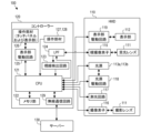
- FIG. 2 is a block diagram showing the electrical configuration of the display system 100.
- the HMD 110 includes a photographic lens 111, a display section 112, light sources 113a and 113b, a light receiving lens 114, an eye image sensor 115, and a knob 140. Further, as shown in FIG. 2, the HMD 110 includes an image sensor 116, a photometry circuit 117, a light source drive circuit 118, and a display drive circuit 119. As shown in FIG. 1B, the display unit 112, light sources 113a and 113b, light receiving lens 114, and eye imaging device 115 are provided for each of the user's right eye and left eye.
- the photographing lens 111 is a lens for capturing an image of the outside world
- the image sensor 116 is an image sensor for capturing an image of the outside world.
- the image sensor 116 is arranged on the intended imaging plane of the photographic lens 111.
- the display unit 112 displays various images (information). For example, the display unit 112 displays an image of the outside world captured by the image sensor 116, or displays information regarding an object that the user is viewing.
- the display unit drive circuit 119 is controlled by a controller 120 (CPU 121 described later) and drives the display unit 112.
- Each of the light sources 113a and 113b is a light source that illuminates the user's eyes, and is, for example, an infrared light emitting diode that emits infrared light that is insensitive to the user.
- the light source drive circuit 118 is controlled by the controller 120 (CPU 121) and drives the light sources 113a and 113b. A portion of the light emitted from the light sources 113a and 113b and reflected by the user's eyes is focused on the eye imaging device 115 by the light receiving lens 114.
- the light receiving lens 114 is a lens for capturing an image of the user's eye
- the eye image sensor 115 is an image sensor for capturing an image of the user's eye.
- the knob 140 is a knob for adjusting the distance between the right eye display section 112 and the left eye display section 112 to match the interpupillary distance of the user.
- the photometric circuit 117 amplifies, logarithmically compresses, and A/D converts a signal obtained from the image sensor 116 that also serves as a photometric sensor, specifically, a luminance signal corresponding to the brightness of the object.
- the result is sent to the controller 120 (CPU 121) as field brightness information.
- the controller 120 includes a CPU 121, a memory section 122, a line of sight detection circuit 123, an LPF (low pass filter) 124, a display section drive circuit 125, operating members 126 to 128, and a wireless communication circuit 129.
- the CPU 121 is a central processing unit of a microcomputer built into the controller 120 and controls the entire display system 100.
- the memory unit 122 has a function of storing video signals from the eye image sensor 115 and a function of storing line of sight correction parameters.
- the line of sight correction parameter is a parameter for correcting individual differences in line of sight.
- the memory unit 122 has a storage function of interest level reference information.
- the interest level reference information is predetermined information corresponding to the object, and is reference information for determining the user's interest level in the object.
- the memory unit 122 stores a plurality of pieces of interest level reference information respectively corresponding to a plurality of objects.
- the line of sight detection circuit 123 A/D converts the output of the eye image sensor 115 (the eye image captured by the eye) in a state where the optical image of the eye is formed on the eye image sensor 115, and converts the result through the LPF 124. and transmits it to the CPU 121.
- the CPU 121 extracts feature points necessary for line-of-sight detection from the eye image according to a predetermined algorithm described later, and detects the user's line-of-sight from the position of the feature point.
- the operation members 126 to 128 accept operations from the user and output operation signals (signals corresponding to the operations performed by the user) to the CPU 121.
- the operating member 126 is a touch panel that can accept touch operations
- the operating member 127 is an operating lever that can be pushed down in each direction
- the operating member 128 is a four-way key that can be pushed down in each of four directions.
- the operation member 126 (touch panel) has a function of displaying images (information). In this way, the operation member 126 has the functions of a touch panel and a display section.
- the display unit drive circuit 125 is controlled by the CPU 121 and drives the operating member 126 (display unit).
- the user can perform various operations (instructions) using the operating members 126 to 128.
- the user can use the operating members 126 to 128 to finely adjust the position of the UI (user interface, such as an indicator) displayed on the display unit 112.
- the wireless communication circuit 129 is controlled by the CPU 121 and communicates with external devices. For example, the wireless communication circuit 129 transmits the degree of interest determined by the CPU 121 (the user's degree of interest in the object) to the server 130 via the Internet and records it.
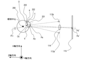
- FIG. 3 is a diagram for explaining the principle of the line of sight detection method, and is a schematic diagram of an optical system for detecting the line of sight.
- the light sources 113a and 113b are arranged substantially symmetrically with respect to the optical axis of the light receiving lens 114, and illuminate the user's eyeball 200.
- FIG. 4A is a schematic diagram of an eye image captured by the eye image sensor 115 (an optical image of the eye projected onto the eye image sensor 115), and FIG. 4B is a diagram showing the output intensity of the eye image sensor 115.
- FIG. 5 is a flowchart of the line of sight detection process.
- step S1 the CPU 121 uses the light source drive circuit 118 to drive the light sources 113a and 113b so as to emit infrared light toward the user's eyeball 200.
- the optical image of the user's eye illuminated by the infrared light passes through the light-receiving lens 114 and forms an image on the eye image sensor 115, and is photoelectrically converted by the eye image sensor 115. This provides an electrical signal of the eye image that can be processed.
- step S2 the CPU 121 acquires an eye image (image data, image signal) from the eye image sensor 115 via the line of sight detection circuit 123.
- step S3 the CPU 121 detects the coordinates of a point corresponding to the corneal reflection images Pd and Pe of the light sources 113a and 113b and the pupil center c from the eye image obtained in step S2.
- the infrared light emitted from the light sources 113a and 113b illuminates the cornea 201 of the user's eyeball 200.
- corneal reflection images Pd and Pe formed by a portion of the infrared light reflected on the surface of the cornea 201 are condensed by the light receiving lens 114 and formed on the eye image sensor 115 to form an image in the eye image.
- the corneal reflection images become Pd' and Pe'.
- the light beams from the ends a and b of the pupil 202 also form images on the eye imaging device 115, forming pupil end images a' and b' in the eye image.
- FIG. 4B shows brightness information (brightness distribution) of area ⁇ in the eye image of FIG. 4A.
- the horizontal direction of the eye image is the X-axis direction
- the vertical direction is the Y-axis direction
- the brightness distribution in the X-axis direction is shown.
- the coordinates of the corneal reflection images Pd' and Pe' in the X-axis direction are Xd and Xe
- the coordinates of the pupil edge images a' and b' in the X-axis direction are Xa and Xb.
- an extremely high level of brightness is obtained at the coordinates Xd and Xe of the corneal reflection images Pd' and Pe'.
- a brightness intermediate between the above two types of brightness can be obtained.
- the X coordinates Xd, Xe of the corneal reflection images Pd', Pe' and the X coordinates Xa, Xb of the pupil edge images a', b' can be obtained.
- coordinates with extremely high brightness can be obtained as the coordinates of the corneal reflection images Pd', Pe'
- coordinates with extremely low brightness can be obtained as the coordinates of the pupil edge images a', b'.
- the pupil center image c' (of the pupil image
- the coordinate Xc of the center) can be expressed as Xc ⁇ (Xa+Xb)/2. That is, the coordinate Xc of the pupil center image c' can be calculated from the X coordinates Xa, Xb of the pupil edge images a', b'. In this way, the coordinates of the corneal reflection images Pd' and Pe' and the coordinates of the pupil center image c' can be estimated.
- step S4 the CPU 121 calculates the imaging magnification ⁇ of the eye image.
- the imaging magnification ⁇ is determined by the position of the eyeball 200 with respect to the light receiving lens 114, and can be calculated using a function of the interval (Xd ⁇ Xe) between the corneal reflection images Pd' and Pe'.
- step S5 the CPU 121 calculates the rotation angle of the optical axis of the eyeball 200 with respect to the optical axis of the light receiving lens 114.
- the X coordinate of the midpoint between the corneal reflection image Pd and the corneal reflection image Pe substantially matches the X coordinate of the center of curvature O of the cornea 201. Therefore, if the standard distance from the center of curvature O of the cornea 201 to the center c of the pupil 202 is Oc, then the rotation angle ⁇ x of the eyeball 200 in the ZX plane (a plane perpendicular to the Y-axis) is as follows: It can be calculated using equation 1.
- the rotation angle ⁇ y of the eyeball 200 within the ZY plane can also be calculated in the same manner as the rotation angle ⁇ x.
- the CPU 121 reads parameters necessary for line of sight detection from the memory unit 122.
- the CPU 121 reads parameters m, Ax, Bx, Ay, By, nx, and ny.
- the parameter m is a constant determined by the configuration of the optical system for performing the line of sight detection processing, and is a conversion coefficient for converting the rotation angles ⁇ x and ⁇ y into coordinates corresponding to the pupil center c on the display unit 112. It is assumed that the parameter m is determined in advance and stored in the memory unit 122.
- the parameters Ax, Bx, Ay, and By are line-of-sight correction parameters for correcting individual differences in line-of-sight, and are obtained by calibrating line-of-sight detection.
- Parameter Ax is an offset value in the X-axis direction
- parameter Bx is a sensitivity coefficient in the X-axis direction
- parameter Ay is an offset value in the Y-axis direction
- the parameter nRx is a correction coefficient in the X-axis direction for obtaining right-eye line-of-sight information
- the parameter nRy is a correction coefficient in the Y-axis direction for obtaining right-eye line-of-sight information
- the parameter nLx is a correction coefficient in the X-axis direction for obtaining left-eye line-of-sight information
- the parameter nLy is a correction coefficient in the Y-axis direction for obtaining left-eye line-of-sight information. It is assumed that the parameters nRx, nRy, nLx, and nLy are determined in advance and stored in the memory unit 122.
- step S7 the CPU 121 uses the rotation angles ⁇ x, ⁇ y calculated in step S5 and the parameters m, Ax, Bx, Ay, By, nx, ny read out in step S6 to Estimate the viewpoint.
- the viewpoint can be considered as the position where the line of sight is focused, the position where the user is looking, or the position of the user's line of sight.
- the coordinates (Hx, Hy) of the viewpoint are coordinates corresponding to the pupil center c
- the coordinates (Hx, Hy) of the viewpoint can be calculated using equations 2 and 3 below.
- Hx m ⁇ (Ax ⁇ x+Bx) ⁇ nx (Formula 2)
- Hy m ⁇ (Ay ⁇ y+By) ⁇ ny...(Formula 3)
- step S8 the CPU 121 stores the coordinates (Hx, Hy) of the viewpoint in the memory unit 122, and ends the line of sight detection process.
- the line of sight detection method is not limited to the above method, and may be any method as long as it acquires line of sight information from an eye image, for example.
- the line of sight may be detected by a method that does not use an eye image, such as a method of detecting an electrooculogram and detecting the line of sight based on the electrooculogram, without using an eye image.
- information indicating the line-of-sight direction may be obtained instead of information indicating the viewpoint.
- processing may be performed to obtain the rotation angles (Ax ⁇ x+Bx) ⁇ nx and (Ay ⁇ y+By) ⁇ ny without obtaining the coordinates (Hx, Hy) of the viewpoint.
- the final line of sight information information indicating the viewpoint of both eyes (the intersection of the line of sight of the right eye and the line of sight of the left eye, the position viewed by both eyes) may be acquired.
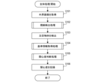
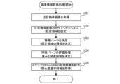
- FIG. 6 is a flowchart of the overall process. For example, when the user wears the HMD 110 and starts the HMD 110 and controller 120, the overall process shown in FIG. 6 starts.
- FIG. 7 is a block diagram showing the functional configuration of the display system 100. Each functional unit in FIG. 7 is realized by the CPU 121 of the controller 120.
- step S101 the external world image acquisition unit 302 acquires an image of the external world (external world image) captured by the image sensor 116.
- the CPU 121 performs predetermined image processing on the acquired external world image and displays it on the display unit 112.
- step S102 the line-of-sight detection unit 301 acquires the user's line-of-sight information by performing the line-of-sight detection process shown in FIG.
- step S103 the CPU 121 detects the object that the user is looking at (object of interest) based on the line of sight information acquired in step S102.
- the object detection unit 303 detects an object from the external world image acquired in step S101.
- the object of interest detection unit 304 detects the object of interest from the objects detected by the object detection unit 303 based on the line of sight information acquired in step S102.
- the object of interest is detected based on information obtained from multiple pieces of time-series gaze information (e.g., the trajectory of the viewpoint, the saccade of the eyeball, the length of time the viewpoint remains, and the number of times the object is fixed). do.
- the object of interest information that is the detection result of the object of interest is acquired. Details of the attention object information will be described later.
- step S104 the reference information acquisition unit 305 acquires interest level reference information corresponding to the object of interest based on the object of interest information obtained in step S103 (reference information acquisition process).
- the reference information acquisition unit 305 acquires interest level reference information corresponding to the object of interest from the memory unit 122. Details of the interest level reference information will be described later.
- the object of interest information indicates the position of the object of interest (the position in real space, the position of the object of interest in the coordinate system of real space (world coordinate system)). It is assumed that the interest level reference information stored in the memory unit 122 is associated with the position of the object corresponding to the interest level reference information. In that case, the reference information acquisition unit 305 may acquire interest level reference information associated with the position closest to the position indicated by the object of interest information from the memory unit 122.
- the object of interest information may indicate the position and type of the object of interest.
- the interest level reference information stored in the memory unit 122 may be associated with the position and type of the object corresponding to the interest level reference information.
- the reference information acquisition unit 305 acquires interest level reference information associated with the position closest to the position indicated by the object of interest information from the memory unit 122 among the objects of the type indicated by the object of interest information. You may obtain it.
- the attention object information may include identification information (for example, an identifier) that identifies (specifies) the attention object.
- the interest level reference information stored in the memory unit 122 may be associated with the identification information of the object corresponding to the interest level reference information. In that case, the reference information acquisition unit 305 may acquire interest level reference information associated with the same identification information as the identification information included in the attention object information from the memory unit 122. .
- a plurality of pieces of interest level reference information corresponding to a plurality of objects may be stored in the server 130.
- the reference information acquisition unit 305 may obtain interest level reference information corresponding to the object of interest from the server 130.
- the process of selecting interest level reference information corresponding to the object of interest from a plurality of pieces of interest level reference information based on the object of interest information may be performed by the reference information acquisition unit 305 or by the server 130.
- the server 130 performs the process of selecting the interest level reference information corresponding to the object of interest, for example, the reference information acquisition unit 305 transmits the object of interest information to the server 130, and the server 130 selects the degree of interest reference information corresponding to the object of interest.
- the reference information is returned to the reference information acquisition unit 305.
- the object of interest detection unit 304 detects the three-dimensional position of the object of interest based on the line-of-sight information of the user's right eye and the line-of-sight information of the user's left eye, and generates the object of interest information indicating the three-dimensional position. good.
- the object of interest detection unit 304 communicates with the user (HMD 110) based on the right eye's line of sight information, the left eye's line of sight information, and the interpupillary distance (the distance between the display section 112 for the right eye and the display section 112 for the left eye). Determine (estimate) the three-dimensional positional relationship with the object of interest.
- the object of interest detection unit 304 detects (estimates) the three-dimensional position of the object of interest based on the three-dimensional position of the user (HMD 110) and the determined positional relationship.
- the three-dimensional position of the user (HMD 110) is estimated using, for example, GPS (Global Positioning System).
- GPS Global Positioning System
- the three-dimensional position of the user (HMD 110) may be estimated by SLAM (Simultaneous Localization and Mapping).
- the three-dimensional position of the user (HMD 110) may be estimated by odometry using an IMU (Inertial Measurement Unit).
- step S104 may be performed. By doing so, the processing load can be reduced.
- step S105 the interest level determining unit 306 determines the user's interest level with respect to the object of interest based on the line of sight information obtained in step S102, the object of interest information obtained in step S103, and the interest level reference information obtained in step S104. Determine level of interest. Details of the process in step S105 (interest level determination process) will be described later.
- step S106 the interest level recording unit 307 transmits the interest level determined in step S105 to the server 130 via the Internet and records it.
- the interest level may be recorded in the memory unit 122.
- FIG. 8A shows an object of interest
- FIG. 8B shows interest level reference information corresponding to the object of interest in FIG. 8A.
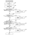
- FIG. 9 is a flowchart of the interest level determination process.
- the object of interest in FIG. 8A is an advertising medium and includes an eye-catching area, a text area, and an image area.
- a catchphrase that has little relevance to the product being advertised is written.
- a description of the product to be advertised and the company name of the product are written.
- An image of the product to be advertised is drawn in the image area located at the lower right of the object of interest.
- the degree of interest reference information in FIG. 8B indicates a standard for determining the user's degree of interest in the object of interest for each of the plurality of regions of the object of interest.
- the interest level reference information in FIG. 8B indicates setting regions 1 to 3 (relative arrangement of each of setting regions 1 to 3 with respect to the entire object of interest).
- Setting area 1 corresponds to an image area
- setting area 2 corresponds to an eye-catching area
- setting area 3 corresponds to a text area.
- the interest level reference information in FIG. 8B indicates the type (image area/eye-catching area/text area), weight, and related area for each of setting areas 1 to 3.
- setting area 2 is set as a related area to setting area 1, and no related area is set in setting areas 2 and 3.
- step S201 the interest level determination unit 306 assigns 0 to the interest level I (initialization of the interest level I).
- the interest level determination unit 306 sets the sensitivity level k of the interest level I.
- the interest level determination unit 306 sets a value according to the user's attributes as the sensitivity level k so that it is easy to obtain a large value as the interest level I of a user who is likely to be interested (and who wants to be interested).
- the object of interest is an advertising medium and the advertising target is cosmetics
- the interest level determination unit 306 is likely to obtain a large value as the interest level of users of the age (age group) and gender targeted by the cosmetics.
- the sensitivity k may be set as follows.
- the interest level determination unit 306 determines whether the user's viewpoint remains in the setting area 1 for a threshold time T1 or more. This determination can also be interpreted as determining whether the user's line of sight is directed toward the setting area 1 for a predetermined threshold time T1 or longer.
- the object of interest information indicates the area of the object of interest in the external world image (the area of the object of interest on the display unit 112).
- the degree of interest determining unit 306 determines the setting area 1 on the display unit 112 based on the object of interest information and the reference level of interest information of the object of interest (relative arrangement of the setting area 1 with respect to the entire object of interest). .
- the interest level determination unit 306 determines whether the viewpoint remains in the set area 1 on the display unit 112 for a threshold time T1 or more based on the line-of-sight information. If the interest level determining unit 306 determines that the user's viewpoint has remained in the setting area 1 for the threshold time T1 or more, the process proceeds to step S211, and if the user's viewpoint has not remained in the setting area 1 for the threshold time T1 or more. If determined, the process advances to step S204.
- the interest level determination unit 306 updates the interest level I using the interest level reference information (weight w1 of setting area 1) of the object of interest.
- the interest level determination unit 306 updates the interest level I to a larger value as the weight w1 is larger.
- step S204 the interest level determining unit 306 determines whether a saccade that moves the viewpoint within the setting area 2 has occurred. If the interest level determining unit 306 determines that a saccade into the setting area 2 has occurred, the process proceeds to step S212; if it determines that a saccade into the setting area 2 has not occurred, the interest level determining unit 306 advances the process to step S212. The process advances to step S205.
- step S205 the interest level determination unit 306 determines whether the user's viewpoint has remained in the setting area 1 for a threshold time T1' or more and the user's viewpoint has remained in the setting area 2 for a threshold time T2 or more. If the interest level determination unit 306 determines that the user's viewpoint has remained in the setting area 1 for the threshold time T1' or longer and the user's viewpoint has remained in the setting area 2 for the threshold time T2 or more, the process proceeds to step S213. , otherwise, the process advances to step S206.
- the eye-catching area corresponding to setting area 2 includes a catchphrase that has low relevance to the product being advertised. Therefore, just because the user looks at the setting area 2, it does not necessarily mean that the user is interested in the object of interest.
- steps S204 and S205 by combining setting area 2 with other parts of the object of interest, it is possible to determine whether or not the user is interested in the object of interest.
- setting area 2 is set as a related area to setting area 1. Therefore, in step S205, setting area 1 and setting area 2 are combined.
- step S206 the interest level determining unit 306 determines whether the user's viewpoint remains in the setting area 3 for a threshold time T3 or more. If the interest level determination unit 306 determines that the user's viewpoint has remained in the setting area 3 for the threshold time T3 or more, the process advances to step S214, and if the user's viewpoint has not remained in the setting area 3 for the threshold time T3 or more, If it is determined, the interest level determination process shown in FIG. 9 is ended.
- the threshold times T1, T1', T2, and T3 may be predetermined fixed times, or may be times that are changed as appropriate.
- the threshold times T1, T1', T2, and T3 may be changed as appropriate by the user, or may be changed as appropriate by the controller 120.
- the controller may determine the visibility of the object of interest based on the external world image, and set a longer time as the lower the visibility of the object of interest as the threshold times T1, T1', T2, and T3.
- the threshold times T1, T1', T2, and T3 may be the same or different.
- the interest level determination process is not limited to the process shown in FIG.
- the interest level reference information only needs to indicate a criterion for determining the user's interest level in the object, and is not limited to the information shown in FIG. 8B.
- the interest level reference information may indicate the order in which the set area is viewed, or may indicate the time at which the set area is desired to be viewed.
- the user's degree of interest in the object of interest can be determined with high accuracy by acquiring and using the predetermined interest level reference information corresponding to the object of interest from the storage unit. can. Furthermore, it is possible to provide a service that presents users with information about products that they are interested in with high precision, and to obtain the number of people who are interested in an object with high precision.
- Example 2 of the present invention will be described.
- description of the same points as Example 1 (for example, the same configuration and processing as Example 1) will be omitted, and points different from Example 1 will be described.
- the overall processing of the second embodiment is the same as that of the first embodiment (FIG. 6).
- the reference information acquisition process in step S104 is different between Example 1 and Example 2.
- interest level reference information corresponding to the object of interest is selected from a plurality of interest level reference information prepared in advance.
- degree-of-interest reference information corresponding to the object of interest is acquired by analyzing an image of the object of interest.
- FIG. 10 is a flowchart of reference information acquisition processing according to the second embodiment.
- the interest level determination process in the second embodiment is the same as the interest level determination process in the first embodiment (FIG. 9).
- step S301 the reference information acquisition unit 305 extracts the region of the object of interest detected in step S103 from the external world image obtained in step S101 in FIG. As a result, an image of the object of interest (an image of the object of interest) is obtained.
- the reference information acquisition unit 305 acquires interest level reference information corresponding to the object of interest by analyzing the object of interest image obtained in step S301.
- step S302 the reference information acquisition unit 305 performs semantic region division (segmentation) of the object of interest image acquired in step S301.
- Setting areas 1 to 3 in FIG. 8B are set by the process in step S302.
- step S303 the reference information acquisition unit 305 detects characteristic parts (for example, characters or objects) from the setting area for each setting area set in step S302, and detects the type of setting area (image area/eye-catching area/ (text area).
- characteristic parts for example, characters or objects
- the reference information acquisition unit 305 determines the weight and related area of the setting area by evaluating the characteristic parts detected in step S303 for each setting area set in step S302.
- the object of interest is an advertising medium
- a large weight is determined for a setting area that is estimated to be in line with the purpose of the advertisement
- a small weight is determined for a setting area that is estimated to be inconsistent with the purpose of the advertisement.
- Good too. For example, a large weight may be determined for an image area where a product to be advertised is depicted, and a low weight may be determined for an eye-catching area where only a catchphrase that is less relevant to the product is described.
- a medium weight may be determined for a text area in which a description of a product is written.
- step S305 the reference information acquisition unit 305 obtains interest level reference information corresponding to the object of interest by integrating the processing results of steps S302 to S304.
- the reference information acquisition unit 305 may use an arithmetic unit (a trained model) that inputs the object image of interest and outputs the analysis result of the object image of interest (for example, the processing result of any one of steps S302 to S305).
- a computing unit may be used for one process among steps S302 to S305, or a computing unit may be used for two or more processes.
- the CPU 121 may function as an arithmetic unit, or the controller 120 may include a GPU (Graphics Processing Unit) that functions as an arithmetic unit.
- the server 130 may analyze the object of interest image and obtain interest level reference information corresponding to the object of interest.
- the reference information acquisition unit 305 transmits the external world image or the object of interest image to the server 130, and the server 130 returns the degree of interest reference information corresponding to the object of interest to the reference information acquisition unit 305.
- the degree of interest reference information corresponding to the object of interest is acquired by analyzing the object of interest image, and the obtained degree of interest reference information is used to improve the user's understanding of the object of interest.
- the degree of interest can be determined with high accuracy.
- the above embodiments are merely examples, and the present invention also includes configurations obtained by appropriately modifying or changing the configuration of the above embodiments within the scope of the gist of the present invention. It will be done.
- the present invention also includes configurations obtained by appropriately combining the configurations of the above embodiments.
- the present invention provides a system or device with a program that implements one or more of the functions of the above-described embodiments via a network or storage medium, and one or more processors in the computer of the system or device reads and executes the program. This can also be achieved by processing. It can also be realized by a circuit (for example, ASIC) that realizes one or more functions.
- a circuit for example, ASIC
- the disclosure of this embodiment includes the following configuration, method, program, and medium.
- (Configuration 1) a first acquisition means for acquiring user's line of sight information; detection means for detecting an object that the user is looking at based on the line of sight information; a second acquisition means for acquiring, from a storage unit, reference information for determining the user's degree of interest in the object, which is predetermined information corresponding to the object;
- An information processing device characterized by comprising: determining means for determining the degree of interest based on the line-of-sight information and the reference information.
- (Configuration 2) a first acquisition means for acquiring user's line of sight information; detection means for detecting an object that the user is looking at based on the line of sight information; a second acquisition means for acquiring reference information for determining the user's degree of interest in the object by analyzing an image of the object;
- An information processing device characterized by comprising: determining means for determining the degree of interest based on the line-of-sight information and the reference information.
- (Configuration 3) The information processing device according to configuration 2, wherein the second acquisition unit acquires the reference information using a trained model that inputs the image and outputs an analysis result of the image.
- the first acquisition means acquires line-of-sight information of the user's right eye and line-of-sight information of the user's left eye, According to any one of configurations 1 to 3, the detection means detects the three-dimensional position of the object based on the line-of-sight information of the user's right eye and the line-of-sight information of the user's left eye.
- Information processing device (Configuration 5) 5.
- the information processing apparatus according to any one of configurations 1 to 4 further comprising recording means for recording the degree of interest on a server.
- Configuration 6) 6.
- the information processing device according to any one of configurations 1 to 5, wherein the reference information indicates a criterion for determining the degree of interest for each of the plurality of regions of the object.
- (Configuration 7) The information processing device according to any one of configurations 1 to 6, a display means;
- a head-mounted display device comprising: (Method 1) a step of obtaining gaze information of the user; detecting an object that the user is looking at based on the line of sight information; acquiring from a storage unit reference information for determining the user's degree of interest in the object, which is predetermined information corresponding to the object;
- a method for controlling an information processing apparatus comprising the step of determining the degree of interest based on the line-of-sight information and the reference information.
- Method 2 a step of obtaining gaze information of the user; detecting an object that the user is looking at based on the line of sight information; acquiring reference information for determining the user's degree of interest in the object by analyzing an image of the object; A method for controlling an information processing apparatus, comprising the step of determining the degree of interest based on the line-of-sight information and the reference information.
- program A program for causing a computer to function as each means of the information processing apparatus according to any one of configurations 1 to 6.
- media A computer-readable storage medium storing a program for causing a computer to function as each means of the information processing apparatus according to any one of configurations 1 to 6.
- Controller 121 CPU 301: Line of sight detection unit 304: Attention object detection unit 305: Reference information acquisition unit 306: Interest level determination unit
Landscapes
- Engineering & Computer Science (AREA)
- Theoretical Computer Science (AREA)
- General Engineering & Computer Science (AREA)
- Physics & Mathematics (AREA)
- General Physics & Mathematics (AREA)
- Human Computer Interaction (AREA)
- Computer Vision & Pattern Recognition (AREA)
- User Interface Of Digital Computer (AREA)
- Image Analysis (AREA)
Abstract
本発明の情報処理装置は、ユーザーの視線情報を取得する第1取得手段と、前記視線情報に基づいて、前記ユーザーが見ている物体を検出する検出手段と、前記物体に対応する所定の情報である、前記物体に対する前記ユーザーの関心度を判断するための基準情報を、記憶部から取得する第2取得手段と、前記視線情報と前記基準情報に基づいて、前記関心度を判断する判断手段とを有することを特徴とする。
Description
本発明は情報処理装置に関し、特に物体に対する人物の関心度を判断する技術に関する。
物体に対する人物の関心度を当該人物の視線情報に基づいて判断する技術が提案されている。特許文献1には、広告表示装置を設置したエリアに存在する人物の視線方向に基づいて、広告表示装置に表示された広告コンテンツを視聴している人数を計測する技術が開示されている。特許文献2には、注視対象物体に対する搭乗者(移動体の搭乗者)の注視持続時間に基づいて、注視対象物体に対する搭乗者の興味度を判定する技術が開示されている。
従来技術(例えば特許文献1,2に開示の技術)では、人物が物体を見る行為を人物が物体に関心を持つ行為とみなして、物体に対する人物の関心度が判断される。しかしながら、人物が物体を見たからといって、当該人物が当該物体に関心を持ったとは限らない。そのため、従来技術では関心度を高精度に判断することができない。
本発明は、物体に対する人物の関心度を高精度に判断することのできる技術を提供することを目的とする。
本発明の第1の態様は、ユーザーの視線情報を取得する第1取得手段と、前記視線情報に基づいて、前記ユーザーが見ている物体を検出する検出手段と、前記物体に対応する所定の情報である、前記物体に対する前記ユーザーの関心度を判断するための基準情報を、記憶部から取得する第2取得手段と、前記視線情報と前記基準情報に基づいて、前記関心度を判断する判断手段とを有することを特徴とする情報処理装置である。
本発明の第2の態様は、ユーザーの視線情報を取得する第1取得手段と、前記視線情報に基づいて、前記ユーザーが見ている物体を検出する検出手段と、前記物体の画像を解析することによって、前記物体に対する前記ユーザーの関心度を判断するための基準情報を取得する第2取得手段と、前記視線情報と前記基準情報に基づいて、前記関心度を判断する判断手段とを有することを特徴とする情報処理装置である。
本発明の第3の態様は、ユーザーの視線情報を取得するステップと、前記視線情報に基づいて、前記ユーザーが見ている物体を検出するステップと、前記物体に対応する所定の情報である、前記物体に対する前記ユーザーの関心度を判断するための基準情報を、記憶部から取得するステップと、前記視線情報と前記基準情報に基づいて、前記関心度を判断するステップとを有することを特徴とする情報処理装置の制御方法である。
本発明の第4の態様は、ユーザーの視線情報を取得するステップと、前記視線情報に基づいて、前記ユーザーが見ている物体を検出するステップと、前記物体の画像を解析することによって、前記物体に対する前記ユーザーの関心度を判断するための基準情報を取得するステップと、前記視線情報と前記基準情報に基づいて、前記関心度を判断するステップとを有することを特徴とする情報処理装置の制御方法である。
本発明の第5の態様は、コンピュータを、上述した情報処理装置の各手段として機能させるためのプログラムである。本発明の第6の態様は、コンピュータを、上述した情報処理装置の各手段として機能させるためのプログラムを格納したコンピュータが読み取り可能な記憶媒体である。
本発明によれば、物体に対する人物の関心度を高精度に判断することができる。
<<実施例1>>
本発明の実施例1について説明する。
本発明の実施例1について説明する。
なお、本発明は、人物の視線情報(視線に関する情報)を取得可能な各種電子機器に適用可能である。例えば、本発明は、ビデオシースルー方式の表示装置にも光学シースルー方式の表示装置にも適用可能である。ビデオシースルー方式の表示装置は、現実空間を撮像した画像(仮想空間)を、必要に応じてグラフィック(例えば仮想物体)を合成して表示面(現実空間(外界)からの光を透過しない表示面)に表示する。この場合に、ユーザーは、現実空間を直接見ることはできないが、表示された画像を見ることによって、現実空間を間接的に見たり、現実空間の画像に合成されたグラフィックを見たりすることができる。光学シースルー方式の表示装置は、例えば、表示面(現実空間からの光を透過する表示面)にグラフィックを表示する。この場合に、ユーザーは、表示面を介して現実空間を直接見たり、表示面に表示されたグラフィックを見たりすることができる。
本発明は、頭部装着型表示装置にも他の表示装置にも適用可能である。例えば、本発明は、ハンドヘルド型表示装置、および据え置き型表示装置にも適用可能である。頭部装着型表示装置は、例えば、スマートグラス(AR(Augmented Reality)グラス)またはHMD(ヘッドマウントディスプレイ)である。ハンドヘルド型表示装置は、例えば、スマートフォンまたはタブレット端末である。ユーザーが手で保持して頭部に装着する(当てる)表示装置は、ハンドヘルド型表示装置の一種であり、頭部装着型表示装置の一種でもある。ヘッドマウントアダプタ(例えばVR(Virtual Reality)ゴーグル)に装着されたスマートフォンは、頭部装着型表示装置の一種である。本発明は、ユーザーが両目で画像を見る頭部装着型表示装置にも、ユーザーが片目で画像を見る頭部装着型表示装置にも適用可能である。
本発明は、現実空間をユーザーに視認させずに仮想空間のみをユーザーに視認させる方式にも適用可能である。つまり、本発明は、様々なXR(Cross Reality)、例えばAR(Augmented Reality)、MR(Mixed Reality)、およびVR(Virtual Reality)に適用可能である。
本発明は、表示装置以外の電子機器にも適用可能である。本発明が適用された情報処理装置は、表示装置に設けられてもよいし、表示装置とは別体の電子機器に設けられてもよい。例えば、本発明は、表示装置に接続されたコントローラーまたはPC(パーソナルコンピュータ)にも適用可能である。本発明は、監視カメラにも適用可能である。
実施例1では、人物の視線情報を取得し、物体に対する人物の関心度を視線情報に基づいて判断する。実施例1では物体が現実物体であるとするが、物体は仮想物体であってもよい。従来技術では、人物が物体を見る行為を人物が物体に関心を持つ行為とみなして、物体に対する人物の関心度が判断される。しかしながら、人物が物体を見たからといって、当該人物が物体に関心を持ったとは限らない。そのため、従来技術では関心度を高精度に判断することができない。
例えば、広告媒体(例えばポスター、看板、およびデジタルサイネージ)は、アイキャッチのための広い領域(アイキャッチ領域)を有することがある。アイキャッチ領域は、例えば、人物(広告モデル)写真またはキャッチフレーズが大きく配置された領域である。ここで、アイキャッチ領域は、広告対象(例えば商品またはサービス)との関連性が低いことがある。そのため、人物がアイキャッチ領域を見たとしても、当該人物は、広告対象を連想せず、広告対象および広告媒体に対して関心を持たないことがある。なお、広告対象との関連性の低い領域は、アイキャッチ領域に限られない。
そこで、実施例1では、物体に応じた好適な判断基準で、物体に対する人物の関心度を高精度に判断する。例えば、物体の内容(物体のデザインの意図)を考慮した判断基準で、関心度を高精度に判断する。
<構成の説明>
図1A,1Bは、実施例1に係る表示システム100の外観を示す。図1Aは正面斜視図であり、図1Bは背面斜視図である。図1Aに示すように、表示システム100は、HMD110、コントローラー120、およびサーバー130を有する。実施例1では、HMD110は、ビデオシースルー方式のHMDとして使用されるとする。コントローラー120は、HMD110に有線で接続されており、サーバー130に無線で接続されている。コントローラー120は、HMD110に無線で接続されてもよい。図2は、表示システム100の電気的構成を示すブロック図である。
図1A,1Bは、実施例1に係る表示システム100の外観を示す。図1Aは正面斜視図であり、図1Bは背面斜視図である。図1Aに示すように、表示システム100は、HMD110、コントローラー120、およびサーバー130を有する。実施例1では、HMD110は、ビデオシースルー方式のHMDとして使用されるとする。コントローラー120は、HMD110に有線で接続されており、サーバー130に無線で接続されている。コントローラー120は、HMD110に無線で接続されてもよい。図2は、表示システム100の電気的構成を示すブロック図である。
図1A,1B,2に示すように、HMD110は、撮影レンズ111、表示部112、光源113a,113b、受光レンズ114、眼撮像素子115、およびツマミ140を有する。さらに、図2に示すように、HMD110は、撮像素子116、測光回路117、光源駆動回路118、および表示部駆動回路119を有する。図1Bに示すように、表示部112、光源113a,113b、受光レンズ114、および眼撮像素子115は、ユーザーの右目と左目のそれぞれについて設けられている。
撮影レンズ111は、外界を撮像するためのレンズであり、撮像素子116は、外界を撮像するための撮像素子である。撮像素子116は、撮影レンズ111の予定結像面に配置されている。
表示部112は、様々な画像(情報)を表示する。例えば、表示部112は、撮像素子116によって撮像された外界の画像を表示したり、ユーザーが見ている物体に関する情報を表示したりする。表示部駆動回路119は、コントローラー120(後述するCPU121)によって制御され、表示部112を駆動する。
光源113aと光源113bのそれぞれは、ユーザーの眼(目)を照明する光源であり、例えばユーザーに対して不感の赤外光を発する赤外発光ダイオードである。光源駆動回路118は、コントローラー120(CPU121)によって制御され、光源113a,113bを駆動する。光源113a,113bから発せられてユーザーの眼で反射した光の一部は、受光レンズ114によって、眼撮像素子115に集光する。受光レンズ114は、ユーザーの眼を撮像するためのレンズであり、眼撮像素子115は、ユーザーの眼を撮像するための撮像素子である。
ツマミ140は、ユーザーの瞳孔間距離に合うように右目用の表示部112と左目用の表示部112との間隔を調整するためのツマミである。
測光回路117は、測光センサの役割を兼ねた撮像素子116から得られる信号、具体的には被写界の明るさに対応した輝度信号の増幅、対数圧縮、およびA/D変換を行い、その結果を被写界輝度情報としてコントローラー120(CPU121)に送る。
コントローラー120は、CPU121、メモリ部122、視線検出回路123、LPF(ローパスフィルタ)124、表示部駆動回路125、操作部材126~128、および無線通信回路129を有する。
CPU121は、コントローラー120に内蔵されたマイクロコンピュータの中央処理部であり、表示システム100全体を制御する。
メモリ部122は、眼撮像素子115からの映像信号の記憶機能と、視線補正パラメータの記憶機能とを有する。視線補正パラメータは、視線の個人差を補正するパラメータである。さらに、メモリ部122は、関心度基準情報の記憶機能を有する。関心度基準情報は、物体に対応する所定の情報であり、物体に対するユーザーの関心度を判断するための基準情報である。メモリ部122は、複数の物体にそれぞれ対応する複数の関心度基準情報を記憶する。
視線検出回路123は、眼撮像素子115上に眼の光学像が結像した状態での眼撮像素子115の出力(眼を撮像した眼画像)をA/D変換し、その結果をLPF124を介してCPU121に送信する。CPU121は、後述する所定のアルゴリズムに従って眼画像から視線検出に必要な特徴点を抽出し、特徴点の位置からユーザーの視線を検出する。
操作部材126~128は、ユーザーからの操作を受け付け、CPU121に操作信号(ユーザーによって行われた操作に応じた信号)を出力する。例えば、操作部材126はタッチ操作を受け付け可能なタッチパネルであり、操作部材127は各方向に押し倒し可能な操作レバーであり、操作部材128は4方向のそれぞれに押し込み可能な4方向キーである。操作部材126(タッチパネル)は、画像(情報)を表示する機能を有する。このように、操作部材126は、タッチパネルとしての機能と、表示部としての機能とを有する。表示部駆動回路125は、CPU121によって制御され、操作部材126(表示部)を駆動する。ユーザーは、操作部材126~128を用いて様々な操作(指示)を行うことができる。例えば、ユーザーは、操作部材126~128を用いて、表示部112に表示されたUI(ユーザーインターフェース、例えば指標)の位置を微調整することができる。
無線通信回路129は、CPU121によって制御され、外部機器と通信を行う。例えば、無線通信回路129は、CPU121によって判断された関心度(物体に対するユーザーの関心度)を、インターネットを介してサーバー130に送信して記録する。
<視線検出処理の説明>
図3,4A,4B,5を用いて、視線検出処理(視線検出方法)について説明する。右目の視線も左目の視線も、以下の視線検出方法で検出される。図3は、視線検出方法の原理を説明するための図であり、視線を検出するための光学系の概略図である。図3に示すように、光源113a,113bは受光レンズ114の光軸に対して略対称に配置され、ユーザーの眼球200を照らす。光源113a,113bから発せられて眼球200で反射した光の一部は、受光レンズ114によって、眼撮像素子115に集光する。図4Aは、眼撮像素子115で撮像された眼画像(眼撮像素子115に投影された眼の光学像)の概略図であり、図4Bは眼撮像素子115の出力強度を示す図である。図5は、視線検出処理のフローチャートである。
図3,4A,4B,5を用いて、視線検出処理(視線検出方法)について説明する。右目の視線も左目の視線も、以下の視線検出方法で検出される。図3は、視線検出方法の原理を説明するための図であり、視線を検出するための光学系の概略図である。図3に示すように、光源113a,113bは受光レンズ114の光軸に対して略対称に配置され、ユーザーの眼球200を照らす。光源113a,113bから発せられて眼球200で反射した光の一部は、受光レンズ114によって、眼撮像素子115に集光する。図4Aは、眼撮像素子115で撮像された眼画像(眼撮像素子115に投影された眼の光学像)の概略図であり、図4Bは眼撮像素子115の出力強度を示す図である。図5は、視線検出処理のフローチャートである。
図5の視線検出処理が開始すると、ステップS1で、CPU121は、ユーザーの眼球200に向けて赤外光を発するように、光源駆動回路118を用いて光源113a,113bを駆動する。赤外光によって照明されたユーザーの眼の光学像は、受光レンズ114を通って眼撮像素子115上に結像し、眼撮像素子115によって光電変換される。これによって、処理可能な眼画像の電気信号が得られる。
ステップS2では、CPU121は、眼撮像素子115から視線検出回路123を介して眼画像(画像データ、画像信号)を取得する。
ステップS3では、CPU121は、ステップS2で得られた眼画像から、光源113a,113bの角膜反射像Pd,Peと瞳孔中心cに対応する点の座標を検出する。
光源113a,113bより発せられた赤外光は、ユーザーの眼球200の角膜201を照明する。このとき、角膜201の表面で反射した赤外光の一部によって形成される角膜反射像Pd,Peは、受光レンズ114によって集光され、眼撮像素子115上に結像して、眼画像における角膜反射像Pd’,Pe’となる。同様に瞳孔202の端部a,bからの光束も眼撮像素子115上に結像して、眼画像における瞳孔端像a’,b’となる。
図4Bは、図4Aの眼画像における領域αの輝度情報(輝度分布)を示す。図4Bでは、眼画像の水平方向をX軸方向、垂直方向をY軸方向とし、X軸方向の輝度分布が示されている。実施例1では、角膜反射像Pd’,Pe’のX軸方向(水平方向)の座標をXd,Xeとし、瞳孔端像a’,b’のX軸方向の座標をXa,Xbとする。図4Bに示すように、角膜反射像Pd’,Pe’の座標Xd,Xeでは、極端に高いレベルの輝度が得られる。瞳孔202の領域(瞳孔202からの光束が眼撮像素子115上に結像して得られる瞳孔像の領域)に相当する、座標Xaから座標Xbまでの領域では、座標Xd,Xeを除いて、極端に低いレベルの輝度が得られる。そして、瞳孔202の外側の虹彩203の領域(虹彩203からの光束が結像して得られる、瞳孔像の外側の虹彩像の領域)では、上記2種の輝度の中間の輝度が得られる。例えば、X座標(X軸方向の座標)が座標Xaより大きい領域と、X座標が座標Xbより小さい領域とで、上記2種の輝度の中間の輝度が得られる。
図4Bに示すような輝度分布から、角膜反射像Pd’,Pe’のX座標Xd,Xeと、瞳孔端像a’,b’のX座標Xa,Xbを得ることができる。例えば、輝度が極端に高い座標を角膜反射像Pd’,Pe’の座標として得ることができ、輝度が極端に低い座標を瞳孔端像a’,b’の座標として得ることができる。受光レンズ114の光軸に対する眼球200の光軸の回転角θxが小さい場合には、瞳孔中心cからの光束が眼撮像素子115上に結像して得られる瞳孔中心像c’(瞳孔像の中心)の座標Xcは、Xc≒(Xa+Xb)/2と表すことができる。つまり、瞳孔端像a’,b’のX座標Xa,Xbから、瞳孔中心像c’の座標Xcを算出できる。このようにして、角膜反射像Pd’,Pe’の座標と、瞳孔中心像c’の座標とを見積もることができる。
ステップS4では、CPU121は、眼画像の結像倍率βを算出する。結像倍率βは、受光レンズ114に対する眼球200の位置によって決まる倍率で、角膜反射像Pd’,Pe’の間隔(Xd-Xe)の関数を用いて算出することができる。
ステップS5では、CPU121は、受光レンズ114の光軸に対する眼球200の光軸の回転角を算出する。角膜反射像Pdと角膜反射像Peの中点のX座標と角膜201の曲率中心OのX座標とはほぼ一致する。このため、角膜201の曲率中心Oから瞳孔202の中心cまでの標準的な距離をOcとすると、Z-X平面(Y軸に垂直な平面)内での眼球200の回転角θxは、以下の式1で算出できる。Z-Y平面(X軸に垂直な平面)内での眼球200の回転角θyも、回転角θxの算出方法と同様の方法で算出できる。
β×Oc×SINθx≒{(Xd+Xe)/2}-Xc ・・・(式1)
β×Oc×SINθx≒{(Xd+Xe)/2}-Xc ・・・(式1)
ステップS6では、CPU121は、視線検出に必要なパラメータをメモリ部122から読み出す。例えば、CPU121は、パラメータm,Ax,Bx,Ay,By,nx,nyを読み出す。パラメータmは、視線検出処理を行うための光学系の構成で定まる定数であり、回転角θx,θyを表示部112上での瞳孔中心cに対応する座標に変換する変換係数である。パラメータmは、予め決定されてメモリ部122に格納されるとする。パラメータAx,Bx,Ay,Byは、視線の個人差を補正する視線補正パラメータであり、視線検出のキャリブレーションを行うことで取得される。パラメータAxはX軸方向のオフセット値であり、パラメータBxはX軸方向の敏感度係数であり、パラメータAyはY軸方向のオフセット値であり、パラメータByはY軸方向の敏感度係数である。視線補正パラメータAx,Bx,Ay,Byは、視線検出処理が開始する前にメモリ部122に格納されるとする。右目の視線検出処理では、パラメータnx=nRxとパラメータny=nRyが取得され、左目の視線検出処理では、パラメータnx=nLxとパラメータny=nLyが取得される。パラメータnRxは、右目の視線情報を得るためのX軸方向の補正係数であり、パラメータnRyは、右目の視線情報を得るためのY軸方向の補正係数である。パラメータnLxは、左目の視線情報を得るためのX軸方向の補正係数であり、パラメータnLyは、左目の視線情報を得るためのY軸方向の補正係数である。パラメータnRx,nRy,nLx,nLyは、予め決定されてメモリ部122に格納されるとする。
ステップS7では、CPU121は、ステップS5で算出した回転角θx,θyと、ステップS6で読み出したパラメータm,Ax,Bx,Ay,By,nx,nyとを用いて、表示部112上でのユーザーの視点を推定する。視点は、視線が注がれた位置と捉えたり、ユーザーが見ている位置と捉えたり、視線位置と捉えたりすることもできる。視点の座標(Hx,Hy)が瞳孔中心cに対応する座標であるとすると、視点の座標(Hx,Hy)は以下の式2,3で算出できる。
Hx=m×(Ax×θx+Bx)×nx ・・・(式2)
Hy=m×(Ay×θy+By)×ny ・・・(式3)
Hx=m×(Ax×θx+Bx)×nx ・・・(式2)
Hy=m×(Ay×θy+By)×ny ・・・(式3)
ステップS8では、CPU121は、視点の座標(Hx,Hy)をメモリ部122に格納し、視線検出処理を終える。
なお、視線検出方法は上記方法に限られず、例えば、眼画像から視線情報を取得する方法であれば、どのような方法であってもよい。眼画像を用いずに、眼電位を検出して当該眼電位に基づいて視線を検出する方法のように、眼画像を用いない方法で視線を検出してもよい。最終的な視線情報として、視点を示す情報ではなく、視線方向(視線の方向)を示す情報が得られてもよい。例えば、視点の座標(Hx,Hy)を得ずに、回転角(Ax×θx+Bx)×nx,(Ay×θy+By)×nyを得るまでの処理が行われてもよい。最終的な視線情報として、両目での視点(右目の視線と左目の視線との交点、両目で見ている位置)を示す情報が取得されてもよい。
<全体処理の説明>
図6,7を用いて、表示システム100(コントローラー120)の全体処理について説明する。図6は、全体処理のフローチャートである。例えば、ユーザーがHMD110を装着して、HMD110とコントローラー120を起動させると、図6の全体処理が開始する。図7は、表示システム100の機能的構成を示すブロック図である。図7の各機能部は、コントローラー120のCPU121によって実現される。
図6,7を用いて、表示システム100(コントローラー120)の全体処理について説明する。図6は、全体処理のフローチャートである。例えば、ユーザーがHMD110を装着して、HMD110とコントローラー120を起動させると、図6の全体処理が開始する。図7は、表示システム100の機能的構成を示すブロック図である。図7の各機能部は、コントローラー120のCPU121によって実現される。
図6の全体処理が開始すると、ステップS101で、外界画像取得部302が、撮像素子116によって撮像された外界の画像(外界画像)を取得する。図6,7には示されていないが、CPU121は、取得した外界画像を、所定の画像処理を施して表示部112に表示する。
ステップS102では、視線検出部301が、図5の視線検出処理を行うことによって、ユーザーの視線情報を取得する。
ステップS103では、CPU121が、ステップS102で取得した視線情報に基づいて、ユーザーが見ている物体(注目物体)を検出する。例えば、物体検出部303が、ステップS101で取得された外界画像から物体を検出する。そして、注目物体検出部304が、ステップS102で取得された視線情報に基づいて、物体検出部303によって検出された物体から、注目物体を検出する。例えば、注目物体は、時系列の複数の視線情報から得られる情報(例えば視点の軌跡、眼球のサッカード、視点が留まっている時間、および物体に対する注視の回数)に基づいて、注目物体を検出する。ステップS103の処理によって、注目物体の検出結果である注目物体情報が取得される。注目物体情報の詳細は後述する。
ステップS104では、基準情報取得部305が、ステップS103で取得された注目物体情報に基づいて、注目物体に対応する関心度基準情報を取得する(基準情報取得処理)。実施例1では、基準情報取得部305は、注目物体に対応する関心度基準情報をメモリ部122から取得する。関心度基準情報の詳細は後述する。
例えば、注目物体情報が注目物体の位置(現実空間内での位置、現実空間の座標系(ワールド座標系)における注目物体の位置)を示すとする。そして、メモリ部122に格納されている関心度基準情報に、当該関心度基準情報に対応する物体の位置が関連付けられているとする。その場合に、基準情報取得部305は、注目物体情報によって示された位置に最も近い位置に関連付けられている関心度基準情報をメモリ部122から取得してもよい。
注目物体情報は、注目物体の位置と種類を示してもよい。そして、メモリ部122に格納されている関心度基準情報に、当該関心度基準情報に対応する物体の位置と種類が関連付けられていてもよい。その場合に、基準情報取得部305は、注目物体情報によって示された種類の物体のうち、注目物体情報によって示された位置に最も近い位置に関連付けられている関心度基準情報をメモリ部122から取得してもよい。
注目物体情報は、注目物体を識別(特定)する識別情報(例えば識別子)を含んでもよい。そして、メモリ部122に格納されている関心度基準情報に、当該関心度基準情報に対応する物体の識別情報が関連付けられていてもよい。その場合に、基準情報取得部305は、基準情報取得部305は、注目物体情報に含まれた識別情報と同じ識別情報に関連付けられている関心度基準情報をメモリ部122から取得してもよい。
なお、複数の物体にそれぞれ対応する複数の関心度基準情報は、サーバー130に格納されていてもよい。その場合に、基準情報取得部305は、注目物体に対応する関心度基準情報をサーバー130から取得してもよい。注目物体情報に基づいて複数の関心度基準情報から注目物体に対応する関心度基準情報を選択する処理は、基準情報取得部305によって行われてもよいし、サーバー130によって行われてもよい。注目物体に対応する関心度基準情報を選択する処理をサーバー130が行う場合には、例えば、基準情報取得部305が注目物体情報をサーバー130に送信し、サーバー130が注目物体に対応する関心度基準情報を基準情報取得部305に返信する。
注目物体検出部304は、ユーザーの右目の視線情報と、ユーザーの左目の視線情報とに基づいて、注目物体の3次元位置を検出し、当該3次元位置を示す注目物体情報を生成してもよい。例えば、注目物体検出部304は、右目の視線情報、左目の視線情報、および瞳孔間距離(右目用の表示部112と左目用の表示部112との間隔)に基づいて、ユーザー(HMD110)と注目物体との3次元的な位置関係を判断(推定)する。そして、注目物体検出部304は、ユーザー(HMD110)の3次元位置と、判断した位置関係とに基づいて、注目物体の3次元位置を検出(推定)する。ユーザー(HMD110)の3次元位置は、例えば、GPS(Global Positioning System)を用いて推定される。3次元位置を用いることによって、2次元位置を用いる場合に比べ高精度に、注目物体に対応する関心度基準情報を取得することができる(注目物体とは異なる物体の関心度基準情報が取得されるという誤動作を抑制できる)。なお、ユーザー(HMD110)の3次元位置の推定方法は、GPSを用いた方法に限られない。例えば、ユーザー(HMD110)の3次元位置は、SLAM(Simultaneous Localization and Mapping)によって推定されてもよい。ユーザー(HMD110)の3次元位置は、IMU(Inertial Measurement Unit)を用いたオドメトリによって推定されてもよい。
特定の種類の物体(例えば広告媒体)に対してのみ関心度基準情報が用意されている場合には、注目物体の種類が特定の種類である場合(例えば注目媒体が広告媒体である場合)に限って、ステップS104の処理が行われてもよい。そうすることによって、処理負荷を軽減することができる。
ステップS105では、関心度判断部306が、ステップS102で取得された視線情報、ステップS103で取得された注目物体情報、およびステップS104で取得された関心度基準情報に基づいて、注目物体に対するユーザーの関心度を判断する。ステップS105の処理(関心度判断処理)の詳細は後述する。
ステップS106で、関心度記録部307が、ステップS105で判断された関心度を、インターネットを介してサーバー130に送信して記録する。関心度はメモリ部122に記録されてもよい。
<関心度判断処理の説明>
図8A,8B,9を用いて、関心度判断処理(図6のステップS105の処理)について説明する。図8Aは注目物体を示し、図8Bは、図8Aの注目物体に対応する関心度基準情報を示す。図9は、関心度判断処理のフローチャートである。
図8A,8B,9を用いて、関心度判断処理(図6のステップS105の処理)について説明する。図8Aは注目物体を示し、図8Bは、図8Aの注目物体に対応する関心度基準情報を示す。図9は、関心度判断処理のフローチャートである。
図8Aの注目物体は広告媒体であり、アイキャッチ領域、文章領域、および画像領域を含む。注目物体の中央上部に配置されたアイキャッチ領域には、広告対象である商品との関連性が低いキャッチフレーズが記載されている。注目物体の中央下部に配置された文章領域には、広告対象である商品の説明、および当該商品の会社名が記載されている。注目物体の右下部に配置された画像領域には、広告対象である商品の画像が描かれている。
図8Bの関心度基準情報は、注目物体の複数の領域のそれぞれについて、注目物体の複数の領域のそれぞれについて、注目物体に対するユーザーの関心度を判断するための基準を示す。図8Bの関心度基準情報は、設定領域1~3(注目物体全体に対する設定領域1~3それぞれの相対的な配置)を示す。設定領域1は画像領域に対応し、設定領域2はアイキャッチ領域に対応し、設定領域3は文章領域に対応する。さらに、図8Bの関心度基準情報は、設定領域1~3のそれぞれについて、種類(画像領域/アイキャッチ領域/文章領域)、重み、および関連領域を示す。図8Bでは、設定領域1の関連領域として設定領域2が設定されており、設定領域2,3には関連領域が設定されていない。
図9の関心度判断処理が開始すると、ステップS201で、関心度判断部306は、関心度Iに0を代入する(関心度Iの初期化)。
ステップS202では、関心度判断部306は、関心度Iの敏感度kを設定する。敏感度kが大きいほど関心度Iは大きくなりやすい。例えば、関心度判断部306は、関心を持ちやすい(関心を持ってもらいたい)ユーザーの関心度Iとして大きい値が得やすくなるように、ユーザーの属性に応じた値を敏感度kとして設定する。注目物体が広告媒体であり且つ広告対象が化粧品である場合には、関心度判断部306は、当該化粧品が対象とする年齢(年齢層)と性別のユーザーの関心度として大きい値が得やすくなるように敏感度kを設定してもよい。
ステップS203では、関心度判断部306は、ユーザーの視点が設定領域1に閾値時間T1以上留まっているか否かを判定する。この判定は、ユーザーの視線が設定領域1に所定の閾値時間T1以上向いているか否かの判定と捉えることもできる。例えば、注目物体情報が、外界画像における注目物体の領域(表示部112上での注目物体の領域)を示す。関心度判断部306は、注目物体情報と、注目物体の関心度基準情報(注目物体全体に対する設定領域1の相対的な配置)とに基づいて、表示部112上での設定領域1を判断する。そして、関心度判断部306は、視線情報に基づいて、表示部112上での設定領域1に視点が閾値時間T1以上留まっているか否かを判定する。関心度判断部306は、ユーザーの視点が設定領域1に閾値時間T1以上留まっていると判定した場合はステップS211に処理を進め、ユーザーの視点が設定領域1に閾値時間T1以上留まっていないと判定した場合はステップS204に処理を進める。
ステップS211では、関心度判断部306は、注目物体の関心度基準情報(設定領域1の重みw1)を用いて、関心度Iを更新する。関心度判断部306は、重みw1が大きいほど大きい値に、関心度Iを更新する。例えば、関心度判断部306は、以下の式4を用いて関心度Iを更新する。
I=I+(1+k)×w1 ・・・(式4)
I=I+(1+k)×w1 ・・・(式4)
ステップS204では、関心度判断部306は、設定領域2内に視点が移動するサッカードが発生しているか否かを判定する。関心度判断部306は、設定領域2内へのサッカードが発生していると判定した場合はステップS212に処理を進め、設定領域2内へのサッカードが発生していないと判定した場合はステップS205に処理を進める。
ステップS212では、関心度判断部306は、注目物体の関心度基準情報(設定領域2の重みw2)を用いて、関心度Iを更新する。例えば、関心度判断部306は、以下の式5を用いて関心度Iを更新する。
I=I+(1+k)×w2 ・・・(式5)
I=I+(1+k)×w2 ・・・(式5)
ステップS205では、関心度判断部306は、ユーザーの視点が設定領域1に閾値時間T1’以上留まっていおり且つユーザーの視点が設定領域2に閾値時間T2以上留まっているか否かを判定する。関心度判断部306は、ユーザーの視点が設定領域1に閾値時間T1’以上留まっていおり且つユーザーの視点が設定領域2に閾値時間T2以上留まっていると判定した場合はステップS213に処理を進め、そうでない場合はステップS206に処理を進める。
ステップS212では、関心度判断部306は、注目物体の関心度基準情報(設定領域1,2の重みw1,w2)を用いて、関心度Iを更新する。例えば、関心度判断部306は、以下の式6を用いて関心度Iを更新する。
I=I+(1+k)×(w1+w2) ・・・(式6)
I=I+(1+k)×(w1+w2) ・・・(式6)
上述したように、設定領域2に対応するアイキャッチ領域には、広告対象である商品との関連性が低いキャッチフレーズが記載されている。そのため、ユーザーが設定領域2を見たからといって、ユーザーが注目物体に関心を持ったとは限らない。ステップS204,S205のように、設定領域2を、注目物体の他の部分と組み合わせることによって、注目物体に対するユーザーの関心の有無を判断することができる。上述したように、設定領域1の関連領域として設定領域2が設定されている。そのため、ステップS205では設定領域1と設定領域2を組み合わせている。
ステップS206では、関心度判断部306は、ユーザーの視点が設定領域3に閾値時間T3以上留まっているか否かを判定する。関心度判断部306は、ユーザーの視点が設定領域3に閾値時間T3以上留まっていると判定した場合はステップS214に処理を進め、ユーザーの視点が設定領域3に閾値時間T3以上留まっていないと判定した場合は図9の関心度判断処理を終了する。
ステップS214では、関心度判断部306は、注目物体の関心度基準情報(設定領域3の重みw3)を用いて、関心度Iを更新する。例えば、関心度判断部306は、以下の式7を用いて関心度Iを更新する。
I=I+(1+k)×w3 ・・・(式7)
I=I+(1+k)×w3 ・・・(式7)
なお、閾値時間T1,T1’,T2,T3は、予め定められた固定時間であってもよいし、適宜変更される時間であってもよい。例えば、閾値時間T1,T1’,T2,T3は、ユーザーによって適宜変更される時間であってもよいし、コントローラー120によって適宜変更される時間であってもよい。コントローラーは、外界画像に基づいて注目物体の視認性を判断し、注目物体の視認性が低いほど長い時間を閾値時間T1,T1’,T2,T3として設定してもよい。閾値時間T1,T1’,T2,T3は同じであってもよいし、異なっていてもよい。
3つの設定領域1~3が設定されている例を説明したが、設定領域の数は特に限定されない。関心度判断処理は、図9に示すような処理に限られない。関心度基準情報は、物体に対するユーザーの関心度を判断するための基準を示していればよく、図8Bに示すような情報に限られない。例えば、関心度基準情報は、設定領域を見る順番を示してもよいし、設定領域を見てほしい時間を示してもよい。
<まとめ>
以上述べたように、実施例1によれば、注目物体に対応する所定の関心度基準情報を記憶部から取得して用いることによって、注目物体に対するユーザーの関心度を高精度に判断することができる。ひいては、ユーザーが関心を持っている商品の情報をユーザーに提示するサービスを高精度に行ったり、物体に関心を持っている人の数を高精度に取得したりすることができる。
以上述べたように、実施例1によれば、注目物体に対応する所定の関心度基準情報を記憶部から取得して用いることによって、注目物体に対するユーザーの関心度を高精度に判断することができる。ひいては、ユーザーが関心を持っている商品の情報をユーザーに提示するサービスを高精度に行ったり、物体に関心を持っている人の数を高精度に取得したりすることができる。
<<実施例2>>
本発明の実施例2について説明する。なお、以下では、実施例1と同じ点(例えば実施例1と同じ構成および処理)についての説明は省略し、実施例1と異なる点について説明する。実施例2の全体処理は、実施例1(図6)の全体処理と同じである。但し、実施例1と実施例2とで、ステップS104の基準情報取得処理が異なる。実施例1の基準情報取得処理では、予め用意された複数の関心度基準情報から注目物体に対応する関心度基準情報が選択される。実施例2の基準情報取得処理では、注目物体の画像を解析することによって、注目物体に対応する関心度基準情報が取得される。図10は、実施例2に係る基準情報取得処理のフローチャートである。実施例2の関心度判断処理は、実施例1(図9)の関心度判断処理と同じである。
本発明の実施例2について説明する。なお、以下では、実施例1と同じ点(例えば実施例1と同じ構成および処理)についての説明は省略し、実施例1と異なる点について説明する。実施例2の全体処理は、実施例1(図6)の全体処理と同じである。但し、実施例1と実施例2とで、ステップS104の基準情報取得処理が異なる。実施例1の基準情報取得処理では、予め用意された複数の関心度基準情報から注目物体に対応する関心度基準情報が選択される。実施例2の基準情報取得処理では、注目物体の画像を解析することによって、注目物体に対応する関心度基準情報が取得される。図10は、実施例2に係る基準情報取得処理のフローチャートである。実施例2の関心度判断処理は、実施例1(図9)の関心度判断処理と同じである。
図10の基準情報取得処理が開始すると、ステップS301で、基準情報取得部305は、図6のステップS101で取得された外界画像から、ステップS103で検出された注目物体の領域を抽出する。これによって、注目物体画像(注目物体の画像)が取得される。
ステップS302~S305では、基準情報取得部305は、ステップS301で取得した注目物体画像を解析することによって、注目物体に対応する関心度基準情報を取得する。
ステップS302では、基準情報取得部305は、ステップS301で取得した注目物体画像の意味的領域分割(セグメンテーション)を行う。ステップS302の処理によって、図8Bの設定領域1~3が設定される。
ステップS303では、基準情報取得部305は、ステップS302で設定した設定領域ごとに、設定領域から特徴パーツ(例えば文字または物体)を検出することによって、設定領域の種類(画像領域/アイキャッチ領域/文章領域)を決定する。
ステップS304では、基準情報取得部305は、ステップS302で設定した設定領域ごとに、ステップS303で検出した特徴パーツを評価することによって、設定領域の重みと関連領域を決定する。注目物体が広告媒体である場合には、広告の趣旨に沿っていると推定される設定領域では大きい重みが決定され、広告の趣旨に沿わないと推定される設定領域では小さい重みが決定されてもよい。例えば、広告対象である商品が描かれた画像領域では大きい重みが決定され、当該商品との関連性が低いキャッチフレーズのみが記載されたアイキャッチ領域では小さい重みが決定されてもよい。そして、商品の説明が記載された文章領域では中程度の重みが決定されてもよい。
ステップS305では、基準情報取得部305は、ステップS302~S304の処理結果を統合することによって、注目物体に対応する関心度基準情報を取得する。
なお、基準情報取得部305は、注目物体画像を入力して注目物体画像の解析結果(例えばステップS302~S305のいずれかの処理結果)を出力する演算器(学習済みモデル)を用いてもよい。ステップS302~S305のうちの1つの処理に演算器が使用されてもよいし、2つ以上の処理に演算器が使用されてもよい。CPU121が演算器として機能してもよいし、コントローラー120が、演算器として機能するGPU(Graphics Processing Unit)を有してもよい。
サーバー130が、注目物体画像を解析して、注目物体に対応する関心度基準情報を取得してもよい。その場合には、例えば、基準情報取得部305が外界画像または注目物体画像をサーバー130に送信し、サーバー130が注目物体に対応する関心度基準情報を基準情報取得部305に返信する。
以上述べたように、実施例2によれば、注目物体画像を解析することによって注目物体に対応する関心度基準情報を取得し、取得した関心度基準情報を用いることによって、注目物体に対するユーザーの関心度を高精度に判断することができる。
なお、上記実施例(変形例を含む)はあくまで一例であり、本発明の要旨の範囲内で上記実施例の構成を適宜変形したり変更したりすることにより得られる構成も、本発明に含まれる。上記実施例の構成を適宜組み合わせて得られる構成も、本発明に含まれる。
<<その他の実施例>>
本発明は、上述の実施例の1以上の機能を実現するプログラムを、ネットワーク又は記憶媒体を介してシステム又は装置に供給し、そのシステム又は装置のコンピュータにおける1つ以上のプロセッサがプログラムを読出し実行する処理でも実現可能である。また、1以上の機能を実現する回路(例えば、ASIC)によっても実現可能である。
本発明は、上述の実施例の1以上の機能を実現するプログラムを、ネットワーク又は記憶媒体を介してシステム又は装置に供給し、そのシステム又は装置のコンピュータにおける1つ以上のプロセッサがプログラムを読出し実行する処理でも実現可能である。また、1以上の機能を実現する回路(例えば、ASIC)によっても実現可能である。
本実施形態の開示は、以下の構成、方法、プログラム、および媒体を含む。
(構成1)
ユーザーの視線情報を取得する第1取得手段と、
前記視線情報に基づいて、前記ユーザーが見ている物体を検出する検出手段と、
前記物体に対応する所定の情報である、前記物体に対する前記ユーザーの関心度を判断するための基準情報を、記憶部から取得する第2取得手段と、
前記視線情報と前記基準情報に基づいて、前記関心度を判断する判断手段と
を有することを特徴とする情報処理装置。
(構成2)
ユーザーの視線情報を取得する第1取得手段と、
前記視線情報に基づいて、前記ユーザーが見ている物体を検出する検出手段と、
前記物体の画像を解析することによって、前記物体に対する前記ユーザーの関心度を判断するための基準情報を取得する第2取得手段と、
前記視線情報と前記基準情報に基づいて、前記関心度を判断する判断手段と
を有することを特徴とする情報処理装置。
(構成3)
前記第2取得手段は、前記画像を入力して前記画像の解析結果を出力する学習済みモデルを用いて、前記基準情報を取得する
ことを特徴とする構成2に記載の情報処理装置。
(構成4)
前記第1取得手段は、前記ユーザーの右目の視線情報と、前記ユーザーの左目の視線情報とを取得し、
前記検出手段は、前記ユーザーの右目の視線情報と、前記ユーザーの左目の視線情報とに基づいて、前記物体の3次元位置を検出する
ことを特徴とする構成1~3のいずれかに記載の情報処理装置。
(構成5)
前記関心度をサーバーに記録する記録手段
をさらに有する
ことを特徴とする構成1~4のいずれかに記載の情報処理装置。
(構成6)
前記基準情報は、前記物体の複数の領域のそれぞれについて、前記関心度を判断するための基準を示す
ことを特徴とする構成1~5のいずれかに記載の情報処理装置。
(構成7)
構成1~6のいずれかに記載の情報処理装置と、
表示手段と、
を有することを特徴とする頭部装着型表示装置。
(方法1)
ユーザーの視線情報を取得するステップと、
前記視線情報に基づいて、前記ユーザーが見ている物体を検出するステップと、
前記物体に対応する所定の情報である、前記物体に対する前記ユーザーの関心度を判断するための基準情報を、記憶部から取得するステップと、
前記視線情報と前記基準情報に基づいて、前記関心度を判断するステップと
を有することを特徴とする情報処理装置の制御方法。
(方法2)
ユーザーの視線情報を取得するステップと、
前記視線情報に基づいて、前記ユーザーが見ている物体を検出するステップと、
前記物体の画像を解析することによって、前記物体に対する前記ユーザーの関心度を判断するための基準情報を取得するステップと、
前記視線情報と前記基準情報に基づいて、前記関心度を判断するステップと
を有することを特徴とする情報処理装置の制御方法。
(プログラム)
コンピュータを、構成1~6のいずれかに記載の情報処理装置の各手段として機能させるためのプログラム。
(媒体)
コンピュータを、構成1~6のいずれかに記載の情報処理装置の各手段として機能させるためのプログラムを格納したコンピュータが読み取り可能な記憶媒体。
本発明は上記実施の形態に制限されるものではなく、本発明の精神及び範囲から離脱することなく、様々な変更及び変形が可能である。従って、本発明の範囲を公にするために以下の請求項を添付する。
本願は、2022年9月2日提出の日本国特許出願特願2022-140049を基礎として優先権を主張するものであり、その記載内容の全てをここに援用する。
120:コントローラー 121:CPU
301:視線検出部 304:注目物体検出部
305:基準情報取得部 306:関心度判断部
301:視線検出部 304:注目物体検出部
305:基準情報取得部 306:関心度判断部
Claims (11)
- ユーザーの視線情報を取得する第1取得手段と、
前記視線情報に基づいて、前記ユーザーが見ている物体を検出する検出手段と、
前記物体に対応する所定の情報である、前記物体に対する前記ユーザーの関心度を判断するための基準情報を、記憶部から取得する第2取得手段と、
前記視線情報と前記基準情報に基づいて、前記関心度を判断する判断手段と
を有することを特徴とする情報処理装置。 - ユーザーの視線情報を取得する第1取得手段と、
前記視線情報に基づいて、前記ユーザーが見ている物体を検出する検出手段と、
前記物体の画像を解析することによって、前記物体に対する前記ユーザーの関心度を判断するための基準情報を取得する第2取得手段と、
前記視線情報と前記基準情報に基づいて、前記関心度を判断する判断手段と
を有することを特徴とする情報処理装置。 - 前記第2取得手段は、前記画像を入力して前記画像の解析結果を出力する学習済みモデルを用いて、前記基準情報を取得する
ことを特徴とする請求項2に記載の情報処理装置。 - 前記第1取得手段は、前記ユーザーの右目の視線情報と、前記ユーザーの左目の視線情報とを取得し、
前記検出手段は、前記ユーザーの右目の視線情報と、前記ユーザーの左目の視線情報とに基づいて、前記物体の3次元位置を検出する
ことを特徴とする請求項1に記載の情報処理装置。 - 前記関心度をサーバーに記録する記録手段
をさらに有する
ことを特徴とする請求項1に記載の情報処理装置。 - 前記基準情報は、前記物体の複数の領域のそれぞれについて、前記関心度を判断するための基準を示す
ことを特徴とする請求項1に記載の情報処理装置。 - 請求項1~6のいずれか1項に記載の情報処理装置と、
表示手段と、
を有することを特徴とする頭部装着型表示装置。 - ユーザーの視線情報を取得するステップと、
前記視線情報に基づいて、前記ユーザーが見ている物体を検出するステップと、
前記物体に対応する所定の情報である、前記物体に対する前記ユーザーの関心度を判断するための基準情報を、記憶部から取得するステップと、
前記視線情報と前記基準情報に基づいて、前記関心度を判断するステップと
を有することを特徴とする情報処理装置の制御方法。 - ユーザーの視線情報を取得するステップと、
前記視線情報に基づいて、前記ユーザーが見ている物体を検出するステップと、
前記物体の画像を解析することによって、前記物体に対する前記ユーザーの関心度を判断するための基準情報を取得するステップと、
前記視線情報と前記基準情報に基づいて、前記関心度を判断するステップと
を有することを特徴とする情報処理装置の制御方法。 - コンピュータを、請求項1~6のいずれか1項に記載の情報処理装置の各手段として機能させるためのプログラム。
- コンピュータを、請求項1~6のいずれか1項に記載の情報処理装置の各手段として機能させるためのプログラムを格納したコンピュータが読み取り可能な記憶媒体。
Applications Claiming Priority (2)
| Application Number | Priority Date | Filing Date | Title |
|---|---|---|---|
| JP2022140049A JP2024035533A (ja) | 2022-09-02 | 2022-09-02 | 情報処理装置 |
| JP2022-140049 | 2022-09-02 |
Publications (1)
| Publication Number | Publication Date |
|---|---|
| WO2024047990A1 true WO2024047990A1 (ja) | 2024-03-07 |
Family
ID=90099298
Family Applications (1)
| Application Number | Title | Priority Date | Filing Date |
|---|---|---|---|
| PCT/JP2023/020973 WO2024047990A1 (ja) | 2022-09-02 | 2023-06-06 | 情報処理装置 |
Country Status (2)
| Country | Link |
|---|---|
| JP (1) | JP2024035533A (ja) |
| WO (1) | WO2024047990A1 (ja) |
Citations (2)
| Publication number | Priority date | Publication date | Assignee | Title |
|---|---|---|---|---|
| JP2007286995A (ja) * | 2006-04-19 | 2007-11-01 | Hitachi Ltd | 注目度計測装置及び注目度計測システム |
| WO2011074198A1 (ja) * | 2009-12-14 | 2011-06-23 | パナソニック株式会社 | ユーザインタフェース装置および入力方法 |
-
2022
- 2022-09-02 JP JP2022140049A patent/JP2024035533A/ja active Pending
-
2023
- 2023-06-06 WO PCT/JP2023/020973 patent/WO2024047990A1/ja unknown
Patent Citations (2)
| Publication number | Priority date | Publication date | Assignee | Title |
|---|---|---|---|---|
| JP2007286995A (ja) * | 2006-04-19 | 2007-11-01 | Hitachi Ltd | 注目度計測装置及び注目度計測システム |
| WO2011074198A1 (ja) * | 2009-12-14 | 2011-06-23 | パナソニック株式会社 | ユーザインタフェース装置および入力方法 |
Also Published As
| Publication number | Publication date |
|---|---|
| JP2024035533A (ja) | 2024-03-14 |
Similar Documents
| Publication | Publication Date | Title |
|---|---|---|
| US10488659B2 (en) | Apparatus, systems and methods for providing motion tracking using a personal viewing device | |
| US11734876B2 (en) | Synthesizing an image from a virtual perspective using pixels from a physical imager array weighted based on depth error sensitivity | |
| US9105210B2 (en) | Multi-node poster location | |
| US9035970B2 (en) | Constraint based information inference | |
| US9348141B2 (en) | Low-latency fusing of virtual and real content | |
| US20200341284A1 (en) | Information processing apparatus, information processing method, and recording medium | |
| US20130326364A1 (en) | Position relative hologram interactions | |
| US20170344110A1 (en) | Line-of-sight detector and line-of-sight detection method | |
| CN110275603A (zh) | 分布式人造现实系统、手镯设备和头戴式显示器 | |
| US11024040B2 (en) | Dynamic object tracking | |
| JP2008009646A (ja) | 画像処理装置、画像処理方法 | |
| KR101467529B1 (ko) | 착용형 정보 제공 시스템 | |
| JP3372926B2 (ja) | ヘッドマウントディスプレイ装置およびヘッドマウントディスプレイシステム | |
| US20190064528A1 (en) | Information processing device, information processing method, and program | |
| US11579449B2 (en) | Systems and methods for providing mixed-reality experiences under low light conditions | |
| KR20190004806A (ko) | 헤드 마운트 디스플레이의 얼굴 센서를 사용한 얼굴과 안구 추적 및 얼굴 애니메이션 | |
| KR20160096392A (ko) | 직관적인 상호작용 장치 및 방법 | |
| WO2019130708A1 (ja) | 情報処理装置、情報処理方法及びプログラム | |
| US20180158242A1 (en) | Information processing method and program for executing the information processing method on computer | |
| US20190088020A1 (en) | Information processing device, information processing method, and program | |
| JP2018088604A (ja) | 画像表示装置、画像表示方法、システム | |
| KR20210101027A (ko) | 전자 장치 및 그 동작 방법 | |
| WO2024047990A1 (ja) | 情報処理装置 | |
| KR20170037692A (ko) | 3차원 디스플레이 장치 및 방법 | |
| JP2024022726A (ja) | 電子機器 |
Legal Events
| Date | Code | Title | Description |
|---|---|---|---|
| 121 | Ep: the epo has been informed by wipo that ep was designated in this application |
Ref document number: 23859760 Country of ref document: EP Kind code of ref document: A1 |