WO2024047749A1 - バリアブルハンドスイッチ - Google Patents
バリアブルハンドスイッチ Download PDFInfo
- Publication number
- WO2024047749A1 WO2024047749A1 PCT/JP2022/032590 JP2022032590W WO2024047749A1 WO 2024047749 A1 WO2024047749 A1 WO 2024047749A1 JP 2022032590 W JP2022032590 W JP 2022032590W WO 2024047749 A1 WO2024047749 A1 WO 2024047749A1
- Authority
- WO
- WIPO (PCT)
- Prior art keywords
- sensor
- main body
- hand switch
- variable hand
- actuating
- Prior art date
- Legal status (The legal status is an assumption and is not a legal conclusion. Google has not performed a legal analysis and makes no representation as to the accuracy of the status listed.)
- Ceased
Links
Images









Classifications
-
- H—ELECTRICITY
- H01—ELECTRIC ELEMENTS
- H01H—ELECTRIC SWITCHES; RELAYS; SELECTORS; EMERGENCY PROTECTIVE DEVICES
- H01H21/00—Switches operated by an operating part in the form of a pivotable member acted upon directly by a solid body, e.g. by a hand
-
- H—ELECTRICITY
- H01—ELECTRIC ELEMENTS
- H01H—ELECTRIC SWITCHES; RELAYS; SELECTORS; EMERGENCY PROTECTIVE DEVICES
- H01H35/00—Switches operated by change of a physical condition
Definitions
- This invention relates to a variable hand switch.
- Variable hand switches are widely used as a means to operate power equipment and measuring equipment at a location away from the main body of the equipment, and are often used in medical settings, particularly in surgical operations.
- Variable hand switches are required to reduce the number of parts. This makes it possible to reduce costs and make it disposable, which is required for a variable hand switch.
- the purpose of this technology is to provide a variable hand switch that makes it possible to reduce the number of parts.
- the variable hand switch according to the present technology is a variable hand switch for outputting a bit signal using infrared rays to a main body device, and includes a main body portion and a variable hand switch arranged so as to gradually move away from the main body portion from one end. an actuating part having a support part whose one end is supported by the main body; and an actuating part disposed between the main body and the actuating part to bias the actuating part in a direction away from the main body.
- an elastic member and a plurality of sensor members arranged in line along the one direction of the main body; By moving the sensor members toward each other or moving them away from the main body part by relying on the elastic force of the elastic member, the plurality of sensor members are sequentially controlled according to the amount of movement of the actuating part. A bit signal is output to the main device.
- the sensor member is a photosensor in which reception and blocking of light is controlled by movement of the actuating part.
- the sensor member is a push button switch in which the ON state and OFF state of the operating portion are controlled by contact with the operating portion.
- variable hand switch according to any one of [1] to [3] includes a power switch that turns on the power to the plurality of sensor members.
- FIG. 3 is a diagram showing an application example of the variable hand switch according to the first embodiment.
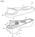
- 1 is a perspective view showing the internal structure of the variable hand switch of Embodiment 1.
- FIG. 1 is an exploded perspective view showing the internal structure of the variable hand switch of Embodiment 1.
- FIG. 2 is a perspective view showing an operating state of the variable hand switch according to the first embodiment.
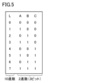
- 3 is a graph showing bit signals of the variable hand switch according to the first embodiment.
- FIG. 3 is a circuit diagram of a light emitting/light receiving section of the variable hand switch according to the first embodiment.
- FIG. 1 is a perspective view showing the internal structure of the variable hand switch of Embodiment 1.
- FIG. 1 is an exploded perspective view showing the internal structure of the variable hand switch of Embodiment 1.
- 2 is
- FIG. 7 is a first perspective view showing an operating state of the variable hand switch according to the second embodiment.
- FIG. 7 is a second perspective view showing the operating state of the variable hand switch according to the second embodiment.
- FIG. 7 is a perspective view showing the internal structure of a variable hand switch according to Embodiment 3;
- FIG. 7 is a plan view of a variable hand switch according to a third embodiment.
- FIG. 7 is a perspective view showing the operating state of the variable hand switch according to the third embodiment.
- FIG. 7 is a plan view showing the operating state of the variable hand switch according to the third embodiment.
- FIG. 7 is a perspective view showing the internal structure of a variable hand switch according to a fourth embodiment.
- FIG. 7 is an exploded perspective view showing the internal structure of a variable hand switch according to a fourth embodiment.
- FIG. 7 is a perspective view showing the operating state of the variable hand switch according to the fourth embodiment.
- FIG. 1 is a diagram showing an application example of the variable hand switch 100
- FIG. 2 is a perspective view showing the internal structure of the variable hand switch 100
- FIG. 3 is an exploded perspective view showing the internal structure of the variable hand switch 100
- FIG. 5 is a perspective view showing the operating state of the variable hand switch 100
- FIG. 5 is a graph showing bit signals of the variable hand switch 100
- FIG. 6 is a circuit diagram of the light emitting/light receiving section of the variable hand switch 100.
- the variable hand switch 100 is used, for example, in angiography examinations, and is applied to control the amount of introduction of an injector head 20 as a main device for introducing a contrast agent or the like in a syringe 30 into a patient. be done.
- Infrared rays are used for communication between the variable hand switch 100 and the injector head 20.
- radio waves are used for communication with the injector head 20
- communication with a different injector head 20 across the room becomes possible, which may lead to erroneous operation. Therefore, it is preferable to use infrared rays to communicate with the injector head 20 of the variable hand switch 100, which does not allow communication across rooms.
- variable hand switch 100 has a main body case 100b and a top case 100a.
- the upper lid case 100a is provided with a control switch cover 11 and a saline switch cover 13.
- Various mechanisms of the variable hand switch are housed within the main body case 100b.
- variable hand switch 100 has a main body substrate 120 as a main body portion extending along one direction (X direction in the figure).
- An actuation plate 110 serving as an actuation section is arranged above the main body substrate 120.
- the actuation plate 110 is arranged to be inclined gradually away from the main body substrate 120 from one end, and has a support portion A1 whose one end is supported by the main body substrate 120.
- a pair of semicircular arc-shaped locking pieces 110a are provided on one side of one end of the actuating plate 110.
- a pair of inwardly directed notches 120a are provided on the side surface of one end of the main body substrate 120.
- the locking piece 110a of the actuation plate 110 engages with the notch 120a of the main body substrate 120, thereby forming a support portion A1, and the actuation plate 110 is attached to the main body substrate 120 using this support portion A1 as a rotational fulcrum. It becomes possible to rotate.
- a saline switch 130 In the main body substrate 120, a saline switch 130, an elastic spring support pin 120b, a sensor power switch 150, and a bit plate through hole 120s are arranged in this order from the notch 120a toward the front side in the figure. There is.
- a mechanical switch is used as the sensor power switch 150.
- the operation button 130b of the saline switch 130 is arranged to face upward.
- the operation button 150b of the sensor power switch 150 is arranged laterally so as to face the bit plate through hole 120s side.
- An elastic spring support pin 110b and a bit plate 180 are provided on the main body substrate 120 side of the actuation plate 110.
- the bit plate 180 is a fan-shaped plate member, and is provided with a plurality of through holes 180h for forming the bit signal shown in FIG. 5.
- a contact portion 180a with which the operation button 150b of the sensor power switch 150 comes into contact is provided on the side surface of the bit plate 180 on the sensor power switch 150 side.
- An elastic spring 140 as an elastic member is held between the elastic spring support pin 110b of the actuation plate 110 and the elastic spring support pin 120b of the main body board 120.
- the elastic force of the elastic spring 140 biases the actuating plate 110 in the direction away from the main body board 120, and the elastic force returns the actuating plate 110 to its original position when the actuating plate 110 is pushed toward the main body board 120. You can gain strength.
- the bit plate through hole 120s is provided in an elongated elliptical shape along the longitudinal direction of the main substrate 120, and a bit plate 180, which will be described later, passes therethrough (see FIG. 4).
- a first sensor 161, a second sensor 162, a third sensor 163, and a fourth sensor 164 are arranged along the longitudinal direction on both sides of the bit plate through hole 120s in a direction crossing the longitudinal direction. ing. Photo sensors are used for each of the first sensor 161, second sensor 162, third sensor 163, and fourth sensor 164.
- the first sensor 161 includes a light emitting element 161a and a light receiving element 161b.
- the second sensor 162 includes a light emitting element 162a and a light receiving element 162b.
- the third sensor 163 includes a light emitting element 163a and a light receiving element 163b.
- the fourth sensor 164 includes a light emitting element 164a and a light receiving element 164b.
- the first sensor 161, the second sensor 162, the third sensor 163, and the fourth sensor 164 constitute a sensor member.
- through holes 180h are provided in the L row of the bit plate 180, and correspond to bit signal intensities "0" to "7".
- rows A, B, and C through holes 180h are provided at positions corresponding to "1" in FIG. Since the actuation plate 110 rotates around the support portion A1, the through holes 180h provided in the L, A, B, and C rows are arranged on an arc centered on the support portion A1. It is set in.
- the L column is a decimal number, and the rows of the A, B, and C columns constitute a binary number (3 bits).
- Control of the amount of contrast agent introduced by operating the actuation plate 110 will be explained.
- the contact portion 180a of the bit plate 180 contacts the operation button 150b of the sensor power switch 150.
- the contact portion 180a of the bit plate 180 turns on the sensor power switch 150.
- each first sensor 161 is turned on. The same applies to other sensors.
- the first sensor 161, the second sensor 162, the third sensor 163, and the fourth sensor 164 are controlled from the OFF state to the ON state, so that the first sensor 161 , the second sensor 162, the third sensor 163, and the fourth sensor 164 can save power when they are in the OFF state.
- variable hand switch 100 is operated remotely using infrared rays using the built-in battery 50, saving power consumption is important. Therefore, at the position where the actuation plate 110 is farthest from the main body substrate 120, the contact portion 180a of the bit plate 180 is separated from the operation button 150b, and the sensor power switch 150 is in the OFF state.
- the actuating plate 110 when the actuating plate 110 is pushed to the third stage, the first sensor 161 and the third sensor 163 are detected in the L2 row, and the amount of contrast agent introduced is controlled to "2".
- the rows of columns A, B, and C constitute a binary number (3 bits).
- the amount of contrast medium introduced can be controlled in eight steps from L0 to L7, depending on the amount of pushing of the actuating plate 110.
- the actuating plate 110 can be moved in the direction approaching the main body substrate 120 against the elastic force of the elastic spring 140, or can be left to the elastic force of the elastic spring 140.
- the plurality of sensor members are sequentially controlled according to the amount of movement of the actuating plate 110, and a bit signal is output to the injector head 20, which is the main body device.
- FIGS. 7 to 10 The configuration of variable hand switch 200 of this embodiment will be described with reference to FIGS. 7 to 10.
- 7 is a perspective view showing the internal structure of the variable hand switch 200
- FIG. 8 is a graph showing bit signals of the variable hand switch 200
- FIGS. It is a 2nd perspective view. Since the configurations of the main body case and the top case of the variable hand switch 200 are the same as those in the first embodiment, only the internal mechanism will be described below.
- the variable hand switch 200 has a main body substrate 250 as a main body extending along one direction (X direction in the figure).
- An actuation plate 270 serving as an actuation section is arranged above the main body substrate 250.
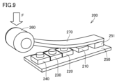
- the actuating plate 270 is curved so as to gradually move away from the main body substrate 250 from one end, and the one end is fixed to the main body substrate 250 via the support member 251.
- the actuating plate 270 is made of an elastic member, and has the role of an elastic member itself disposed between the main body substrate 250 and the actuating plate 270.
- a contrast button 260 for operating the operating plate 270 is provided at the tip of the operating plate 270.
- a first sensor 210 On the main body substrate 250, a first sensor 210, a second sensor 220, a third sensor 230, and a fourth sensor 240 are arranged in this order from the support member 251 toward the front side in the drawing.
- a mechanical switch is used for each sensor.
- the graph showing the bit signals shown in FIG. 8 is used to control the amount of contrast agent introduced, but in this embodiment, the graph is simplified. Specifically, as shown in FIG. 9, when the first sensor 210 is turned on by gradually pushing the actuating plate 270 in the direction of the arrow F in the figure, the amount of introduction is controlled to the position of the L1 row. Next, when the first sensor 210 and the second sensor 220 are turned on, the introduction amount is controlled to the position of the L3 column. Next, when the first sensor 210, the second sensor 220, and the third sensor 230 are turned on, the introduction amount is controlled to the position of the L7 column. Next, when the first sensor 210, the second sensor 220, the third sensor 230, and the fourth sensor 240 are turned on, the introduction amount is controlled to the position of the L15 column.
- the actuation plate 270 can be moved in a direction approaching the main body substrate 250 against the elastic force of the actuation plate 270 itself, or moved away from the main body substrate 250 by relying on the elastic force of the actuation plate 270 itself.
- a plurality of sensor members are sequentially controlled according to the amount of movement of the actuation plate 270, and a bit signal is output to the injector head 20, which is the main device.
- FIG. 11 is a perspective view showing the internal structure of the variable hand switch 300
- FIG. 12 is a plan view of the variable hand switch 300
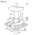
- FIG. 13 is a perspective view showing the operating state of the variable hand switch 300
- FIG. 14 is a perspective view showing the variable hand switch 300.
- 3 is a plan view showing the operating state of the switch 300.
- the variable hand switch 300 has a main body substrate 380 as a main body.
- the main body substrate 380 is square in plan view, but one reference direction (X direction in the figure) is from the fulcrum axis 350a of the spiral-shaped actuation plate 350, which will be described later, to the actuation plate. 350 is the tangential direction from which the spiral begins.
- An actuation plate 350 serving as an actuation section is arranged above the main body substrate 250 and extends upward in a spiral shape.
- the fulcrum shaft 350a of the actuation plate 350 is fixed to a fixed block 390 provided on the actuation plate 350.
- a cylindrical bearing hole 390a is provided in the fixed block 390, and a fulcrum shaft 350a is rotatably supported in this bearing hole 390a.
- the fulcrum shaft 350a of the actuating plate 350 is rotatable in the vertical direction about the bearing hole 390a.
- the actuating plate 350 as an elastic member is made of a resin spring.
- Actuation plate 350 has an annular spiral shape.
- a vertical sliding rod 360 is arranged at the center, and the vertical sliding rod 360 is provided to be slidable in the vertical direction through a through hole (not shown) provided in a main body substrate 380.
- a contrast button 370 is attached to the upper end of the vertical sliding rod 360.
- the actuation plate 350 is provided in a range of 360 degrees in a plan view, and the other end is fixed to a vertical sliding rod 360 via a fixing ring 340s.
- a first sensor 310, a second sensor 320, a third sensor 330, and a fourth sensor 340 are arranged in a circular shape counterclockwise along the spiral shape of the actuation plate 350. are arranged in order.
- a mechanical switch is used for each sensor.
- the graph showing the bit signals shown in FIG. 8 is used to control the amount of contrast agent introduced.
- the introduction amount is controlled to the position of the L1 row.
- the introduction amount is controlled to the position of the L3 column.
- the introduction amount is controlled to the position of the L7 column.
- the introduction amount is controlled to the position of the L15 column.
- the actuation plate 350 can be moved in a direction approaching the main body substrate 380 against the elastic force of the actuation plate 350 itself, or moved away from the main body substrate 380 by relying on the elastic force of the actuation plate 350 itself.
- a plurality of sensor members are sequentially controlled according to the amount of movement of the actuating plate 350, and a bit signal is output to the injector head 20, which is the main device.
- the injector head 20 which is the main device.
- FIGS. 15 to 17 The configuration of variable hand switch 400 of this embodiment will be described with reference to FIGS. 15 to 17.
- 15 is a perspective view showing the internal structure of the variable hand switch 400
- FIG. 16 is an exploded perspective view showing the internal structure of the variable hand switch 400
- FIG. 17 is a perspective view showing the operating state of the variable hand switch 400. .
- variable hand switch 400 has a main body substrate 450 as a main body.
- main body substrate 450 is square in plan view, but one reference direction (X direction in the figure) is the direction in which a rod-shaped actuating section 460, which will be described later, extends.
- the actuating portion 460 has a shape that extends in the vertical direction, and passes through a through hole 450s provided in the main body substrate 450.
- a coil spring 480 is provided as an elastic member for biasing the actuating part 460 upward, and a support member 470 that supports the coil spring 480 and is fixed to the lower surface of the main body substrate 450. It has a lid member 470b that closes the bottom surface of the support member 470.
- the support member 470 is provided with a cross-shaped groove 470s through which the main body substrate 450 passes.
- a first vertical rib 460a, a second vertical rib 460b, a third vertical rib 460c, and a fourth vertical rib 460d are provided on the outer peripheral surface of the operating portion 460 at a pitch of 90 degrees so as to extend in the vertical direction. .
- a sensor power switch 430 On the surface of the main body substrate 450, a sensor power switch 430, a first sensor 461, A second sensor 462 and a third sensor 463 are arranged.
- a mechanical switch is used as the sensor power switch 430.
- Sensor power switch 430 includes an operation button 430b.
- a photointerrupter In which a light emitting part and a light receiving part are integrated is used.
- a first vertical rib 460a provided on the circumferential surface of the operating portion 460 is provided with a first uneven portion 460a1 for controlling the sensor power switch 430 provided at a corresponding position.
- the second vertical rib 460b is provided with a second uneven portion 460b1 for controlling the first sensor 461 provided at a corresponding position.
- the third vertical rib 460c is provided with a third uneven portion 460c1 for controlling the second sensor 462 provided at a corresponding position.
- the fourth vertical rib 460d is provided with a fourth uneven portion 460d1 for controlling a third sensor 463 provided at a corresponding position.
- the first uneven portion 460a1 is retracted to a position where it does not contact the operation button 430b of the sensor power switch 430.
- the second uneven portion 460b1 protrudes to a position that blocks the sensor portion of the first sensor 461.
- the third uneven portion 460c1 protrudes to a position that blocks the sensor portion of the second sensor 462.
- the fourth uneven portion 460d1 protrudes to a position that blocks the sensor portion of the third sensor 463.
- the first uneven part 460a1 remains in contact with the operation button 430b of the sensor power switch 430.
- the second uneven portion 460b1 is in a state where the sensor portion of the first sensor 461 is opened (concave state).
- the first sensor 461 becomes in a state of detecting light reception.
- the second sensor 462 remains blocked by the third uneven portion 460c1 and does not detect light reception.
- the third sensor 463 also remains blocked by the fourth uneven portion 460d1 and does not detect light reception.
- the first uneven part 460a1 continues to be in contact with the operation button 430b of the sensor power switch 430.
- the second uneven portion 460b1 remains in the state (recessed state) in which the sensor portion of the first sensor 461 is opened. Therefore, the first sensor 461 is in a state of detecting light reception.
- the second sensor 462 is in a state where the third uneven portion 460c1 opens the sensor portion (recessed state) (see FIG. 17). Thereby, the second sensor 462 enters a state of detecting light reception.
- the third sensor 463 remains blocked by the fourth uneven portion 460d1 and does not detect light reception.
- the first uneven part 460a1 continues to be in contact with the operation button 430b of the sensor power switch 430.
- the second uneven portion 460b1 remains in a state in which the sensor portion of the first sensor 461 is opened (in a recessed state). Therefore, the first sensor 461 remains in the state of detecting light reception.
- the second sensor 462 is in a state where the third uneven portion 460c1 opens the sensor portion (concave state). Therefore, the second sensor 462 remains in the state of detecting light reception.
- the fourth uneven portion 460d1 is in a state in which the sensor portion of the third sensor 463 is opened (in a recessed state). Therefore, the third sensor 463 is in a state of detecting light reception.
- the graph showing the bit signals shown in FIG. 8 is used to control the amount of contrast agent introduced. Specifically, as shown in FIG. 8, when the actuating part 460 is pushed to the second stage pushing state, the first sensor 461 is turned on, and the introduction amount is controlled to the position of the L1 row.
- the first sensor 421, the second sensor 462, and the third sensor 463 are turned on, and the introduction amount is controlled to the position of the L7 row.
- the actuating section 460 is moved toward the main body substrate 450 against the elastic force of the coil spring 480, or moved away from the main body substrate 450 by relying on the elastic force of the coil spring 480. Accordingly, a plurality of sensor members are sequentially controlled according to the amount of movement of the actuating section 460, and a bit signal is output to the injector head 20, which is the main device. As a result, like the variable hand switch 100 of Embodiment 1, it is possible to reduce the number of parts, and it is possible to reduce costs and make the variable hand switch 400 disposable.
Landscapes
- Switches Operated By Changes In Physical Conditions (AREA)
Priority Applications (2)
| Application Number | Priority Date | Filing Date | Title |
|---|---|---|---|
| PCT/JP2022/032590 WO2024047749A1 (ja) | 2022-08-30 | 2022-08-30 | バリアブルハンドスイッチ |
| JP2024543654A JPWO2024047749A1 (https=) | 2022-08-30 | 2022-08-30 |
Applications Claiming Priority (1)
| Application Number | Priority Date | Filing Date | Title |
|---|---|---|---|
| PCT/JP2022/032590 WO2024047749A1 (ja) | 2022-08-30 | 2022-08-30 | バリアブルハンドスイッチ |
Publications (1)
| Publication Number | Publication Date |
|---|---|
| WO2024047749A1 true WO2024047749A1 (ja) | 2024-03-07 |
Family
ID=90099172
Family Applications (1)
| Application Number | Title | Priority Date | Filing Date |
|---|---|---|---|
| PCT/JP2022/032590 Ceased WO2024047749A1 (ja) | 2022-08-30 | 2022-08-30 | バリアブルハンドスイッチ |
Country Status (2)
| Country | Link |
|---|---|
| JP (1) | JPWO2024047749A1 (https=) |
| WO (1) | WO2024047749A1 (https=) |
Citations (6)
| Publication number | Priority date | Publication date | Assignee | Title |
|---|---|---|---|---|
| JPH0214736U (https=) * | 1988-07-13 | 1990-01-30 | ||
| JPH06178783A (ja) * | 1992-12-14 | 1994-06-28 | G C:Kk | 歯科治療用ハンドピースの制御装置 |
| WO2006109691A1 (ja) * | 2005-04-07 | 2006-10-19 | Nemoto Kyorindo Co., Ltd. | 多段検出装置 |
| JP2007287440A (ja) * | 2006-04-14 | 2007-11-01 | Kyocera Mita Corp | 入力装置及び画像形成装置 |
| JP2013255741A (ja) * | 2012-06-14 | 2013-12-26 | Hitachi Medical Corp | X線装置及びx線撮像装置 |
| JP2020038415A (ja) * | 2018-09-03 | 2020-03-12 | スーガン株式会社 | 出力可変ハンドスイッチ |
-
2022
- 2022-08-30 JP JP2024543654A patent/JPWO2024047749A1/ja active Pending
- 2022-08-30 WO PCT/JP2022/032590 patent/WO2024047749A1/ja not_active Ceased
Patent Citations (6)
| Publication number | Priority date | Publication date | Assignee | Title |
|---|---|---|---|---|
| JPH0214736U (https=) * | 1988-07-13 | 1990-01-30 | ||
| JPH06178783A (ja) * | 1992-12-14 | 1994-06-28 | G C:Kk | 歯科治療用ハンドピースの制御装置 |
| WO2006109691A1 (ja) * | 2005-04-07 | 2006-10-19 | Nemoto Kyorindo Co., Ltd. | 多段検出装置 |
| JP2007287440A (ja) * | 2006-04-14 | 2007-11-01 | Kyocera Mita Corp | 入力装置及び画像形成装置 |
| JP2013255741A (ja) * | 2012-06-14 | 2013-12-26 | Hitachi Medical Corp | X線装置及びx線撮像装置 |
| JP2020038415A (ja) * | 2018-09-03 | 2020-03-12 | スーガン株式会社 | 出力可変ハンドスイッチ |
Also Published As
| Publication number | Publication date |
|---|---|
| JPWO2024047749A1 (https=) | 2024-03-07 |
Similar Documents
| Publication | Publication Date | Title |
|---|---|---|
| US7292741B2 (en) | Multi-input optical switch | |
| JP4057862B2 (ja) | 複合操作型入力装置 | |
| EP2991091B1 (en) | Multi-directional operation switch | |
| US4939320A (en) | Self-setting switch-actuating assembly and method | |
| US12109688B2 (en) | Mechanical hand | |
| US20050030278A1 (en) | Adjustable pointing and control device with automatic handedness switch | |
| CN109008903B (zh) | 一种内窥镜操作部和内窥镜 | |
| WO2024047749A1 (ja) | バリアブルハンドスイッチ | |
| WO2001013194A1 (fr) | Dispositif d'entree multidirectionnel | |
| BRPI0721455A2 (pt) | Dispositivo de navegação para um dispositivo eletrônico, e, dispositivo eletrônico. | |
| JP2009064638A (ja) | 複合操作装置 | |
| US7075526B2 (en) | Button simulating rotation of input device roller | |
| US12042931B2 (en) | Mechanical hand | |
| JP4617216B2 (ja) | 多方向入力装置 | |
| CN109216090A (zh) | 操纵杆式电子开关 | |
| JP3657469B2 (ja) | 多方向入力装置 | |
| JP7654060B2 (ja) | 多方向出力デバイス | |
| US8644001B2 (en) | Electronic apparatus | |
| JP3751522B2 (ja) | ポインティング装置 | |
| JP3810691B2 (ja) | 携帯時計 | |
| JP2011171186A (ja) | 揺動型多方向スイッチ装置 | |
| KR20080054369A (ko) | 문자, 아이콘 및/또는 다중 선택과 같은 심볼 선택 장치 | |
| CN223693035U (zh) | 控制器切换按键结构及控制器装置 | |
| WO2024018806A1 (ja) | 操作装置及び操作ユニット | |
| WO2024176787A1 (ja) | 検出装置および操作装置 |
Legal Events
| Date | Code | Title | Description |
|---|---|---|---|
| 121 | Ep: the epo has been informed by wipo that ep was designated in this application |
Ref document number: 22957352 Country of ref document: EP Kind code of ref document: A1 |
|
| WWE | Wipo information: entry into national phase |
Ref document number: 2024543654 Country of ref document: JP |
|
| NENP | Non-entry into the national phase |
Ref country code: DE |
|
| 122 | Ep: pct application non-entry in european phase |
Ref document number: 22957352 Country of ref document: EP Kind code of ref document: A1 |