WO2024047719A1 - 前照灯装置用光源分配素子及び前照灯モジュール - Google Patents
前照灯装置用光源分配素子及び前照灯モジュール Download PDFInfo
- Publication number
- WO2024047719A1 WO2024047719A1 PCT/JP2022/032476 JP2022032476W WO2024047719A1 WO 2024047719 A1 WO2024047719 A1 WO 2024047719A1 JP 2022032476 W JP2022032476 W JP 2022032476W WO 2024047719 A1 WO2024047719 A1 WO 2024047719A1
- Authority
- WO
- WIPO (PCT)
- Prior art keywords
- light
- section
- light guide
- projection
- reflective
- Prior art date
- Legal status (The legal status is an assumption and is not a legal conclusion. Google has not performed a legal analysis and makes no representation as to the accuracy of the status listed.)
- Ceased
Links
Images


Classifications
-
- F—MECHANICAL ENGINEERING; LIGHTING; HEATING; WEAPONS; BLASTING
- F21—LIGHTING
- F21S—NON-PORTABLE LIGHTING DEVICES; SYSTEMS THEREOF; VEHICLE LIGHTING DEVICES SPECIALLY ADAPTED FOR VEHICLE EXTERIORS
- F21S41/00—Illuminating devices specially adapted for vehicle exteriors, e.g. headlamps
- F21S41/20—Illuminating devices specially adapted for vehicle exteriors, e.g. headlamps characterised by refractors, transparent cover plates, light guides or filters
- F21S41/25—Projection lenses
- F21S41/27—Thick lenses
-
- F—MECHANICAL ENGINEERING; LIGHTING; HEATING; WEAPONS; BLASTING
- F21—LIGHTING
- F21S—NON-PORTABLE LIGHTING DEVICES; SYSTEMS THEREOF; VEHICLE LIGHTING DEVICES SPECIALLY ADAPTED FOR VEHICLE EXTERIORS
- F21S41/00—Illuminating devices specially adapted for vehicle exteriors, e.g. headlamps
- F21S41/20—Illuminating devices specially adapted for vehicle exteriors, e.g. headlamps characterised by refractors, transparent cover plates, light guides or filters
- F21S41/25—Projection lenses
- F21S41/265—Composite lenses; Lenses with a patch-like shape
Definitions
- the present disclosure relates to a light source distribution element and a headlamp module used in a headlamp device that illuminates the front of a vehicle body.
- Patent Document 1 proposes a light source distribution element for a headlamp device that has a simplified structure and is miniaturized without reducing light utilization efficiency.
- the light source distribution element for a headlamp device proposed in Patent Document 1 is located between a first joint surface of an input section and a first output section, and transmits light from the first joint surface of the input section.
- the light source distribution element for a headlamp device proposed in Patent Document 1 has a simple structure and can be downsized without reducing light utilization efficiency.
- An object of the present invention is to obtain a light source distribution element for a headlamp device that is further miniaturized without reducing usage efficiency.
- a light source distribution element for a headlamp device includes an entrance portion into which light from a light source is incident and which has a plurality of joint surfaces of three or more located along one direction in a plane orthogonal to the optical axis of the light source. and a pair of opposing surfaces facing in one direction and the other direction orthogonal to each other in a plane perpendicular to the optical axis of the light source.
- a plurality of light guide parts having three or more surfaces, each of which guides light from a corresponding joint surface to a corresponding output surface, and one end of the plurality of light guide parts in the other direction with respect to the light source;
- a pair of opposing surfaces of the light guide section with an output surface located on one side have a pair of reflective surfaces tilted with respect to the optical axis of the light source on one end side.
- the pair of opposing surfaces of the light guide section, on which the output surface is located on the other end side have a pair of reflective surfaces on the other end side that are inclined with respect to the optical axis of the light source.
- the structure can be simplified and further miniaturized without reducing light utilization efficiency.
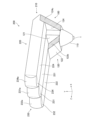
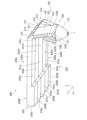
- FIG. 2 is a perspective view of the headlamp module according to Embodiment 1, seen from above on the right side.
- FIG. 2 is a perspective view of the headlamp module according to Embodiment 1, seen from below on the left side.
- 1 is a front view showing a headlamp module according to Embodiment 1.
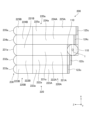
- FIG. 1 is a top view showing a headlamp module according to Embodiment 1.
- FIG. 3 is a bottom view showing the headlamp module according to the first embodiment.
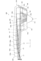
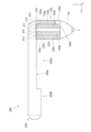
- 1 is a side view showing a headlamp module according to Embodiment 1.
- FIG. FIG. 2 is a partially cross-sectional front view showing the entrance portion of the headlamp module according to the first embodiment.
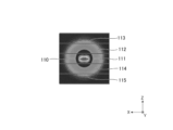
- FIG. 3 is a diagram showing the illuminance distribution at the joint surface at the entrance part of the headlamp module according to the first embodiment.
- FIG. 2 is a perspective view of the headlamp module according to the first embodiment, viewed from above on the right side, showing the luminous flux.
- FIG. 2 is a perspective view of the headlamp module according to the first embodiment, viewed from below on the left side, showing a luminous flux.
- FIG. 7 is a perspective view of a headlamp module according to a second embodiment, viewed from above on the right side.
- FIG. 7 is a perspective view of the headlamp module according to Embodiment 2, seen from below on the left side.
- FIG. 7 is a front view showing a headlamp module according to a second embodiment.
- FIG. 7 is a top view showing a headlamp module according to a second embodiment.
- FIG. 7 is a bottom view showing a headlamp module according to a second embodiment.
- FIG. 3 is a side view showing a headlamp module according to a second embodiment.
- FIG. 7 is a perspective view of the headlamp module according to Embodiment 2, viewed from above, showing the luminous flux of the headlamp module.
- FIG. 7 is a perspective view of the headlamp module according to Embodiment 2, viewed from below, showing the luminous flux of the headlamp module.
- FIG. 7 is a perspective view of a headlamp module according to Embodiment 3, seen from above on the right side.
- FIG. 7 is a perspective view of a headlamp module according to Embodiment 3, seen from below on the left side.
- FIG. 7 is a front view showing a headlamp module according to a third embodiment.
- FIG. 7 is a top view showing a headlamp module according to Embodiment 3;
- FIG. 7 is a bottom view showing a headlamp module according to Embodiment 3;
- FIG. 7 is a side view showing a headlamp module according to Embodiment 3;
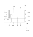
- FIG. 7 is an enlarged perspective view from the right side showing a light source distribution element and a condensing optical section in a headlamp module according to Embodiment 3;
- FIG. 7 is an enlarged perspective view from the left side showing a light source distribution element and a condensing optical section in a headlamp module according to Embodiment 3;
- FIG. 7 is a perspective view of a headlamp module according to Embodiment 4, seen from above on the right side.
- FIG. 7 is a perspective view of a headlamp module according to Embodiment 4, viewed from below on the left side.
- FIG. 7 is a front view showing a headlamp module according to a fourth embodiment.
- FIG. 7 is a top view showing a headlamp module according to a fourth embodiment.
- FIG. 7 is a bottom view showing a headlamp module according to a fourth embodiment.
- FIG. 7 is a side view showing a headlamp module according to a fourth embodiment.
- Embodiment 1 A light source distribution element 100 for a headlamp device (hereinafter abbreviated as light source distribution element 100) and a headlamp module according to Embodiment 1 will be described based on FIGS. 1 to 10.
- the headlamp module satisfies the predetermined light distribution pattern stipulated by road traffic regulations, etc., and is suitable for automobiles, motorcycles, three-wheeled vehicles called gyros (scooters made of three wheels with one wheel in the front and two wheels in the rear, and motorized vehicles). Used in headlight devices that illuminate the front of bicycles.
- the headlight device has a low beam and a high beam.
- the headlamp module according to Embodiment 1 can be used for low beams and high beams, and is particularly suitable for use for low beams.
- the present invention is applied to a low beam of an automobile headlamp device.
- the number of headlamp modules may be one, or a plurality of headlamp modules may be arranged in parallel in the left-right direction.
- Light distribution refers to the luminous intensity distribution of a light source in space. In other words, it is the spatial distribution of light emitted from a light source.
- Luminous intensity indicates the intensity of light emitted by a light emitter, and is the luminous flux passing within a small solid angle in a certain direction divided by that small solid angle.
- the low beams of automobile headlight devices and motorcycle headlight devices are required to have a horizontal light distribution pattern that is narrow in the vertical direction. It is required that the upper light boundary line, that is, the cutoff line, be clear.
- the light distribution pattern indicates the shape of a luminous flux and the intensity distribution of light caused by the direction of light emitted from the light source 1.
- the light distribution pattern is also used to mean the illuminance pattern on the irradiation surface.
- the light distribution is the distribution of light intensity in the direction of light emitted from a light source.
- Light distribution is also used to mean illuminance distribution on the irradiation surface.
- a clear required cutoff line means that the area above the cutoff line, that is, the outside of the light distribution pattern, is dark, and the area below the cutoff line, that is, the inside of the light distribution pattern, is bright.
- the cut-off line is a dividing line between bright and dark light that is created when a wall or screen is irradiated with light from a headlamp device, and is a dividing line on the upper side of a light distribution pattern. That is, the cut-off line is the boundary line between bright and dark light on the upper side of the light distribution pattern. It is the boundary line between the bright area above the light distribution pattern, that is, the inside of the light distribution pattern, and the dark area, ie, the outside of the light distribution pattern.
- the cut-off line is a term used when adjusting the irradiation direction of a headlamp device for passing vehicles. A headlight device for passing each other is also called a low beam.
- Low beams are required to provide maximum illumination in the area below the cutoff line.
- This region of maximum illuminance is called a high illuminance region.
- the area below the cut-off line means the upper part of the light distribution pattern, and corresponds to the part that illuminates a distant area in a headlamp device.
- the cutoff line In order to achieve a clear cutoff line, the cutoff line must not have large chromatic aberrations or blurring. Blurring of the cut-off line means that the cut-off line becomes unclear.
- the cutoff line has a stepped shape with a rising line.
- the cut-off line is a straight line horizontally in the left-right direction of the vehicle, and the light distribution pattern is brightest in the area below the cut-off line, that is, the area inside the light distribution pattern.
- the headlight device since the headlight device is placed on the front of the vehicle, design is important, and there is a need for a headlight device with a higher degree of freedom in design. If the headlight device is made thinner in the vertical direction of the vehicle in order to improve its design, the efficiency of light utilization will be low.
- the light source distribution element 100 and the headlamp module according to the first embodiment improve the design by reducing the vertical thickness of the light output surface of the light source distribution element 100, and satisfy Abbe's invariant (Abbe's sine condition). It is possible to miniaturize the light without reducing the efficiency of light use by focusing on the conservation law of etendue. That is, by making the light source distribution element 100 have a plurality of three or more, preferably five, output surfaces, the length of one side of the output surface of the light source distribution element 100, which serves as an apparent light source, can be made smaller. It can be made smaller.
- the left and right direction of the vehicle is defined as the X-axis direction.
- the right side is the + direction of the X-axis
- the left side is the - direction of the X-axis.
- the term "front" refers to the direction in which the vehicle is traveling. That is, the front is the direction in which the headlamp device emits light.
- the X-axis direction is the other direction
- one end side is the ⁇ direction (right side)
- the other end side is the + direction (left side).
- one end side is referred to as the right side and the other end side as the left side, this is specified for convenience of explanation, and the one end side may be referred to as the left side and the other end side as the right side.
- the vertical direction of the vehicle is the Y-axis direction.
- the upper side is the + direction of the Y-axis
- the lower side is the - direction of the Y-axis.
- the upper side is the direction of the sky
- the lower side is the direction of the ground (road surface, etc.).
- Let the direction of travel of the vehicle be the Z-axis direction.
- the direction of movement is defined as the + direction of the Z-axis
- the opposite direction is defined as the - direction of the Z-axis.
- the + direction of the Z-axis is called the front
- the - direction of the Z-axis is called the rear.
- the + direction of the Z-axis is the direction in which the headlight emits light.
- the Z-axis direction is one direction, one end side is the + direction when used for an automobile, the other end side is the - direction, when used for an automobile. If so, it is at the rear.
- the ZX plane is parallel to the road surface.
- a road surface is usually considered to be a horizontal plane, ie, a plane perpendicular to the direction of gravity.
- the road surface may be inclined, such as uphill or downhill, with respect to the direction in which the vehicle is traveling.
- a horizontal plane that is parallel to the road surface is not necessarily a plane perpendicular to the direction of gravity, but a horizontal plane that is perpendicular to the direction of gravity is a plane, and a Z-X plane is a plane that is perpendicular to the direction of gravity. The following explanation is given as a plane.
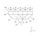
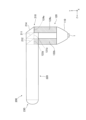
- the headlamp module includes a light source distribution element 100 and a light distribution forming part 200.
- the headlamp device further includes a light source 1 in addition to the headlamp module.
- the light source 1 emits light for illuminating the front of the vehicle.
- the light source 1 is disposed on the - side of the Y-axis of the light source distribution element 100, and emits light in the + direction of the Y-axis.
- the optical axis of the light source 1 is an axis along the Y-axis direction.
- the light source 1 has a rectangular output surface that outputs light on the front side.
- the light source 1 is a tube light source such as an incandescent lamp, a halogen lamp, or a fluorescent lamp, a light emitting diode (LED), or a laser diode (LD). ) or other semiconductor light sources.
- the headlamp device uses an LED, which is one of semiconductor light sources.
- the light source distribution element 100 and the light distribution forming section 200 are integrally formed of a transparent material, and the interface between the components does not have a physical interface but a virtual interface. It is. However, when the light source distribution element 100 is used alone, the output surfaces 121a to 125a of the light source distribution element 100 are physically exposed surfaces, and when used as a headlamp module, the light distribution forming part 200 When assembled, the light emitting surfaces 121a to 125a of the light source distribution device 100 are coupled to the light distribution forming part 200.
- the headlamp module is manufactured by injection molding and is made of a transparent material filled with a refractive material.
- the material from which the headlamp module is manufactured is preferably a material that has high transparency from the viewpoint of light utilization efficiency and has excellent heat resistance since the light source distribution element 100 is disposed immediately after the light source 1.
- transparent resin such as glass or silicone material is good.
- acrylic resin especially PMMA: polymethyl methacrylate
- PC polycarbonate
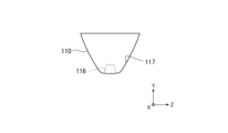
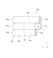
- the light source distribution element 100 includes an incident part 110 and a collective light guide part 120.
- the incident part 110 is a collimator that has a conical shape, has a lens 116 at its apex, and has a bottom surface of the conical shape as a joint surface of the collective light guide part 120.
- the joint surface has a diameter of 20 mm, for example.
- the light emitted from the light source 1 enters the lens 116, and guides parallel light, ideally parallel light, to the cemented surface.
- light rays with a small emission angle are incident on the lens 116 and then directly guided to the conical bottom surface of the entrance section 110 (the joint surface of the collective light guide section 120).
- light rays having a large emission angle enter the lens 116 , are reflected by the reflective surface 117 , and are guided to the conical bottom surface of the incident part 110 .
- the light beam directly guided from the lens 116 and the light beam reflected and guided by the reflective surface 117 are guided as parallel light to the joint surface of the collective light guide section 120.
- FIG. 8 shows the illuminance distribution at the joint surface of the light source distribution element 100 when an LED that emits light with a long length in the X-axis direction is used as the light source 1.
- the joint surfaces of the light source distribution element 100 have the same length, that is, the same width, along one direction in a plane perpendicular to the optical axis of the light source 1, that is, the Z-axis direction.
- a first bonding surface 111 that is divided and located in the center, a second bonding surface 112 and a third bonding surface 113 that are located in order from the center to one end side in one direction, that is, on the + side of the Z axis, and a center portion.
- the first bonding surface 111 to the fifth bonding surface 115 are virtual surfaces indicating interfaces with the collective light guide section 120.
- the collective light guide section 120 has a joint surface that joins the joint surface of the incident section 110.
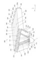
- the collective light guide section 120 has five output surfaces arranged on a plane parallel to the joint surface of the incident section 110, that is, the ZX plane, and without overlapping in the Z-axis direction and the X-axis direction. It has a first output surface 121a to a fifth output surface 125a, and guides the light from the joint surface of the input section 110 from the first output surface 121a to the fifth output surface 125a.
- the fifth output surface 125a, the fourth output surface 124a, the first output surface 121a, the second output surface 122a, and the third output surface 123a are arranged in this order from the other end side.
- the fifth output surface 125a, the fourth output surface 124a, the first output surface 121a, the second output surface 122a, and the third output surface 123a are arranged in this order from the other end side.
- the first to fifth output surfaces 121a to 125a are rectangular, have the same length W in the X-axis direction, and have the same length in the Z-axis direction. Note that the lengths of the respective emission surfaces in the X-axis direction may be different.
- the collective light guide section 120 includes a first light guide section 121 to a fifth light guide section 125.
- the first light guide section 121 to the fifth light guide section 125 each have a pair of opposing surfaces that face each other parallel to the X-axis direction in the plane ZX plane perpendicular to the optical axis of the light source 1, that is, the Y-axis. It is a columnar body having a rectangular shape in the Z-X cross section.
- the first light guide section 121 has a first output surface 121a, and guides the light from the first joint surface 111 of the input section 110 to the first output surface 121a.
- the first light guiding section 121 has a pair of opposing surfaces parallel to the Y axis, stands upright from the first joint surface 111 of the incident section 110, and is formed integrally with the incident section 110. The distance between the pair of opposing surfaces along the X-axis direction is W.
- the first light guide section 121 has a rectangular parallelepiped shape that connects linearly from the first joint surface 111 of the incident section 110 to the first output surface 121a.
- the first light guiding section 121 causes the light from the first joint surface 111 of the incident section 110 to proceed straight to the first output surface 121a along the Y axis, as shown as a light beam L1 in FIGS. 9 and 10. .
- the second light guide section 122 has a second output surface 122a, and guides the light from the second joint surface 112 of the input section 110 to the second output surface 122a.
- a pair of opposing surfaces in the second light guide section 122 have a pair of reflective surfaces, that is, a first reflective surface 122b located at the center in the X-axis direction and a second reflective surface 122c located at one end.
- the first reflective surface 122b and the second reflective surface 122c are each the entire surface of a pair of opposing surfaces.
- the second light guiding section 122 is formed integrally with the incident section 110 such that the first reflecting surface 122b and the second reflecting surface 122c are each inclined at 45 degrees toward one end with respect to the second bonding surface 112. Ru.
- the second light guide section 122 is integrated with the incident section 110 such that the first reflective surface 122b and the second reflective surface 122c are each inclined at 45 degrees toward one end with respect to the optical axis of the light source 1. It is formed.
- the distance between the first reflective surface 122b and the second reflective surface 122c along the X-axis direction is W.
- the second light guide section 122 includes a first light guide section 122 that linearly connects the second joint surface 112 of the entrance section 110 to the second exit surface 122a at an angle of 45 degrees toward one end with respect to the second joint surface 112.
- the reflective surface 122b and the second reflective surface 122c have a columnar shape in which the distance along the X-axis direction is W.
- 45 degrees does not indicate a strict 45 degrees, but refers to a range of 45 degrees ⁇ taking into account design margins, etc. ⁇ . Also in the following description, 45 degrees refers to the range of 45 degrees ⁇ .
- the angle at which the reflective surface is tilted does not need to be limited to 45 degrees. Since it is desirable that the reflective surface be a total reflective surface, the ideal angle of inclination is about 45 degrees. However, in the case of a mirror surface formed by metal vapor deposition or the like, the angle of inclination can be freely designed. However, it is desirable that the reflective surface functions as a total reflection surface. This is because a total reflection surface has a higher reflectance than a mirror surface and contributes to improving the efficiency of light use. Further, by eliminating the mirror vapor deposition process, the manufacturing process of the light source distribution element 100 can be simplified, contributing to a reduction in the manufacturing cost of the light source distribution element 100.
- the second light guiding section 122 directs the light from the second joint surface 112 of the incident section 110 to the second reflecting surface 122c via the first reflecting surface 122b, as shown as a light beam L2 in FIGS. 9 and 10.
- the light is totally reflected, and the second reflecting surface 122c totally reflects it to the second exit surface 122a, and guides it to the second exit surface 122a.
- the second light guiding section 122 ultimately guides the light from the second joint surface 112 of the incident section 110 to the second exit surface 122a as parallel light along the Y-axis.
- the third light guide section 123 has a third output surface 123a, and guides the light from the third joint surface 113 of the input section 110 to the third output surface 123a.
- a pair of opposing surfaces in the third light guide section 123 have a pair of reflective surfaces, that is, a third reflective surface 123b located at the center in the X-axis direction and a fourth reflective surface 123c located at one end.
- the third light guiding section 123 is formed integrally with the incident section 110 such that the third reflecting surface 123b and the fourth reflecting surface 123c are each inclined at 45 degrees toward one end with respect to the third joint surface 113. Ru.
- the third light guiding section 123 is integrated with the incident section 110 such that the third reflecting surface 123b and the fourth reflecting surface 123c are each inclined at 45 degrees toward one end with respect to the optical axis of the light source 1. It is formed.
- the distance between the third reflective surface 123b and the fourth reflective surface 123c along the X-axis direction is 2W, which is twice W.
- the third light guide section 123 has a length of 2W along the X-axis direction, and has a columnar shape inclined at 45 degrees toward one end with respect to the third joint surface 113.
- the fourth reflective surface 123c of the third light guide section 123 is moved in the other direction by the length W in the other direction of the third output surface 123a from the position of the second reflective surface 122c of the second light guide section 122. It is located far away from one end of the .
- the third light guiding section 123 directs the light from the third joint surface 113 of the incident section 110 to the fourth reflecting surface 123c through the third reflecting surface 123b, as shown as a light beam L3 in FIGS. 9 and 10.
- the light is totally reflected, and the fourth reflecting surface 123c totally reflects it to the third exit surface 123a, and guides it to the third exit surface 123a.
- the third light guide section 123 ultimately guides the light from the third joint surface 113 of the entrance section 110 to the third output surface 123a as parallel light along the Y axis.
- the third reflective surface 123b of the third light guide section 123 is continuous with the first reflective surface 122b of the second light guide section 122 on one end side in the Z-axis direction.
- the third light guiding section 123 is a second guiding section from the third joint surface 113 of the incident section 110 to the position of the first reflecting surface 122b of the second light guiding section 122 and the position of the second reflecting surface 122c. It is formed integrally with the light section 122.
- the fourth reflective surface 123c of the third light guide section 123 extends from the position of the second reflective surface 122c of the second light guide section 122 by the length W of the third output surface 123a in the X-axis direction. It is located far away on one end of the direction. That is, the distance between the third reflective surface 123b and the fourth reflective surface 123c along the X-axis direction is the It is twice the distance W along the axial direction, that is, 2W.
- the third light guide section 123 has a shape in which two second light guide sections 122 are arranged in parallel in the X-axis direction.
- the portion from the third reflective surface 123b of the third light guide section 123 to the second reflective surface 122c of the second light guide section 122 is formed integrally with the second light guide section 122.
- a common light guide section has a shape in which two second light guide sections 122 are arranged in parallel in the Z-axis direction. From the position of the first reflecting surface 122b of the second light guiding section 122 to the position of the second reflecting surface 122c, the boundary surface between the second light guiding section 122 and the third light guiding section 123 is a physical boundary. It does not have a surface, but a virtual surface.
- the fourth light guide section 124 has a fourth output surface 124a, and guides the light from the fourth joint surface 114 of the input section 110 to the fourth output surface 124a.
- a pair of opposing surfaces in the fourth light guiding section 124 have a pair of reflective surfaces, that is, a fifth reflective surface 124b located at the center in the X-axis direction and a sixth reflective surface 124c located at the other end. .
- the fifth reflective surface 124b and the sixth reflective surface 124c are each the entire surface of a pair of opposing surfaces.
- the fourth light guide section 124 is formed integrally with the incident section 110 such that the fifth reflective surface 124b and the sixth reflective surface 124c are each inclined at 45 degrees toward the other end with respect to the fourth joint surface 114. be done.
- the fourth light guiding section 124 is integrated with the incident section 110 such that the fifth reflecting surface 124b and the sixth reflecting surface 124c are each inclined at 45 degrees toward one end with respect to the optical axis of the light source 1. It is formed.
- the distance between the fifth reflective surface 124b and the sixth reflective surface 124c along the X-axis direction is W.
- the fourth light guide section 124 is a fourth light guide section 124 that linearly connects the fourth joint surface 114 of the incident section 110 to the fourth output surface 124a at an angle of 45 degrees toward the other end with respect to the fourth joint surface 114.
- the fifth reflective surface 124b and the sixth reflective surface 124c have a columnar shape in which the interval along the X-axis direction is W.
- the fourth light guiding section 124 directs the light from the fourth joint surface 114 of the incident section 110 to the sixth reflecting surface 124c through the fifth reflecting surface 124b, as shown as a light beam L4 in FIGS. 9 and 10.
- the light is totally reflected, and the sixth reflecting surface 124c totally reflects it to the fourth exit surface 124a, and guides it to the fourth exit surface 124a.
- the fourth light guide section 124 ultimately guides the light from the fourth joint surface 114 of the entrance section 110 to the fourth output surface 124a as parallel light along the Y-axis.
- the shape of the fourth light guide section 124 and the shape of the second light guide section 122 are line symmetrical with respect to the Y axis.
- the fifth light guide section 125 has a fifth output surface 125a, and guides the light from the fifth joint surface 115 of the input section 110 to the fifth output surface 125a.
- a pair of opposing surfaces in the fifth light guide section 125 have a pair of reflective surfaces, that is, a seventh reflective surface 125b located at the center in the X-axis direction and an eighth reflective surface 125c located at the other end. .
- the fifth light guide section 125 is formed integrally with the incident section 110 such that the seventh reflective surface 125b and the eighth reflective surface 125c are each inclined at 45 degrees toward the other end with respect to the fifth joint surface 115. be done.
- the fifth light guiding section 125 is integrated with the incident section 110 such that the seventh reflecting surface 125b and the eighth reflecting surface 125c are each inclined at 45 degrees toward one end with respect to the optical axis of the light source 1. It is formed.
- the distance between the seventh reflective surface 125b and the eighth reflective surface 125c along the X-axis direction is 2W, which is twice W.
- the fifth light guide section 125 has a length of 2W along the X-axis direction, and has a columnar shape inclined at 45 degrees toward the other end with respect to the fifth joint surface 115.
- the eighth reflective surface 125c of the fifth light guide section 125 extends in the other direction from the position of the sixth reflective surface 124c of the fourth light guide section 124 by the length W in the other direction of the fifth output surface 125a. It is located far away from the other end.
- the fifth light guiding section 125 directs the light from the fifth joint surface 115 of the incident section 110 to the eighth reflecting surface 125c via the seventh reflecting surface 125b, as shown as a light beam L5 in FIGS. 9 and 10.
- the light is totally reflected, and the eighth reflecting surface 125c totally reflects it to the fifth exit surface 125a, and guides it to the fifth exit surface 125a.
- the fifth light guide section 125 ultimately guides the light from the fifth joint surface 115 of the entrance section 110 to the fifth output surface 125a as parallel light along the Y-axis.
- the seventh reflective surface 125b of the fifth light guide section 125 is continuous with the fifth reflective surface 124b of the fourth light guide section 124 on the other end side in the Z-axis direction.
- the fifth light guide section 125 extends from the fifth joint surface 115 of the incident section 110 to the position of the fifth reflective surface 124b of the fourth light guide section 124 and the position of the sixth reflective surface 124c. It is formed integrally with the light section 124.
- the eighth reflective surface 125c of the fifth light guide section 125 extends from the position of the sixth reflective surface 124c of the fourth light guide section 124 by the length W of the fifth output surface 125a in the X-axis direction. It is located far away towards the other end of the direction. That is, the distance between the seventh reflective surface 125b and the eighth reflective surface 125c along the X-axis direction is equal to the distance between the fifth reflective surface 124b and the sixth reflective surface 124c in the fourth light guide section This is twice the distance W along the axial direction, that is, 2W.
- the fifth light guide section 125 has a shape in which two fourth light guide sections 124 are arranged in parallel in the X-axis direction.
- the portion from the seventh reflective surface 125b of the fifth light guide section 125 to the sixth reflective surface 124c of the fourth light guide section 124 is formed integrally with the fourth light guide section 124.
- a common light guide section From the position of the fifth reflective surface 124b of the fourth light guide section 124 to the position of the sixth reflective surface 124c, and from the position of the seventh reflective surface 125b of the fifth light guide section 125 to the fourth light guide section Up to the position of the sixth reflective surface 124c of 124, a common light guide section has a shape in which two fourth light guide sections 124 are arranged in parallel in the Z-axis direction.
- the boundary surface between the fourth light guide section 124 and the fifth light guide section 125 is a physical boundary. It does not have a surface, but a virtual surface.
- the shape of the fifth light guide section 125 and the shape of the third light guide section 123 are line symmetrical with respect to the Y axis.
- the collective light guide section 120 has three or more exit surfaces, preferably five, so that collective light guide can be performed without reducing the light utilization efficiency of the light from the light source 1.
- the point that the height to the output surface of the section 120 can be reduced will be explained.
- the apparent size of a light source is defined by "Abbe's invariant", which is determined by the product of the divergence angle of the light source in a certain direction and the length of the side of the light source in that direction.
- the height of the light source that is, the length in the vertical direction
- the vertical divergence angle of the light from the light source is ⁇ 0
- the length in the vertical direction of the emission surface that is, the length of the vertical side.
- the apparent height of the light source can be reduced. Since the light from the light source 1 is collimated by the incident part 110 and divided into five light beams, the length of the side in the Z-axis direction of the output surface of the collective light guide part 120 can be reduced, and the first output surface The length of the side in the Z-axis direction of the fifth output surface 125a from 121a can be reduced.
- the light source distribution element 100 according to Embodiment 1 is applied to a headlamp module, the height of the projection surface can be reduced, and miniaturization can be achieved.
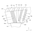
- the light distribution forming section 200 converts light in the Y-axis direction from the exit surface of the collective light guide section 120 in the light source distribution element 100, from the first exit surface 121a to the fifth exit surface 125a in the first embodiment, into the Z-axis direction. The light is totally reflected forward and guided from the projection surface, in the first embodiment, from the first projection surface 231a to the fifth projection surface 235a.
- the light distribution forming section 200 includes a collective light collecting optical section 210, a collective light distribution section 220, and a projection section 230.
- the light distribution forming section 200 is integrally formed of a transparent material.
- the collective light condensing optical section 210 totally reflects the light from the output surface of the collective light guide section 120 forward and downward in the Z-axis direction and condenses the light.
- the collective light collecting optical part 210 is formed integrally with the collective light guiding part 120.
- the collective light collecting optical part 210 includes a first light collecting optical part 211 to a fifth light collecting optical part 215.
- the first condensing optical section 211 to the fifth condensing optical section 215 are arranged from the other end side along the X-axis to the fifth condensing optical section 215, the fourth condensing optical section 214, and the first condensing optical section 215.
- a condensing optical section 211, a second condensing optical section 212, and a third condensing optical section 213 are arranged in this order.
- the first condensing optical part 211 has a joint surface that joins with the first output surface 121a of the first light guide part 121, and a joint surface that faces the joint surface and is located on one end side of the Z axis with respect to the joint surface. It has a reflecting surface that is tilted forward and has a light gathering function, a pair of parallel opposing surfaces along the X-axis, and a front surface located at one end of the Z-axis that serves as an exit for the light reflected on the reflecting surface. .
- the length of the joint surface of the first condensing optical section 211 along the X axis, the distance between the pair of opposing surfaces of the first condensing optical section 211, and the front surface of the first condensing optical section 211 The length along the X-axis is W, which is the same as the length W in the X-axis direction of the first output surface 121a.
- the reflective surface is a flat surface that is tilted forward by less than 45 degrees with respect to the cemented surface, and may have a curved surface depending on the application.
- the first condensing optical section 211 reflects the light from the first output surface 121a of the first light guiding section 121 forward and downward in the Z-axis direction using a reflective surface, and condenses the light.
- the joint surface of the first condensing optical section 211 and the first output surface 121a of the first light guide section 121 are not physically joined surfaces but virtual surfaces. be.
- the second condensing optical part 212 has a joint surface that joins with the second output surface 122a of the second light guide part 122, and a joint surface that faces the joint surface and is located on one end side of the Z axis with respect to the joint surface. It has a reflecting surface that is tilted forward and has a light condensing function, a pair of parallel opposing surfaces along the X-axis, and a front surface located on one end side of the Z-axis that serves as an exit for the light reflected by the reflecting surface.
- the length along the X-axis is W, which is the same as the length W in the X-axis direction of the second exit surface 122a.
- the reflective surface is a flat surface that is inclined forward at less than 45 degrees with respect to the cemented surface, and may have a curved surface depending on the application.
- the second condensing optical section 212 reflects the light from the second output surface 122a of the second light guiding section 122 forward and downward in the Z-axis direction using a reflecting surface, and condenses the light.
- the joint surface of the second condensing optical section 212 and the second output surface 122a of the second light guide section 122 are not physically joined surfaces but virtual surfaces. be.
- the third condensing optical part 213 has a joint surface that joins with the third output surface 123a of the third light guide part 123, and is located opposite to the joint surface and on one end side of the Z axis, that is, in front of the joint surface. It has a reflecting surface that is tilted downward and has a light collecting function, a pair of parallel opposing surfaces along the X axis, and a front surface located at one end of the Z axis that serves as an exit for the light reflected on the reflecting surface. .
- the length of the joint surface of the third condensing optical section 213 along the X axis, the distance between the pair of opposing surfaces of the third condensing optical section 213, and The length along the X-axis is W, which is the same as the length W in the X-axis direction of the third output surface 123a.
- the reflective surface is a flat surface that is inclined forward at less than 45 degrees with respect to the cemented surface, and may have a curved surface depending on the application.
- the third condensing optical section 213 reflects the light from the third output surface 123a of the third light guide section 123 forward and downward in the Z-axis direction by a reflecting surface and condenses the light. Note that in the first embodiment, the joint surface of the third condensing optical section 213 and the third output surface 123a of the third light guide section 123 are not physically joined surfaces but virtual surfaces. be.
- the fourth condensing optical section 214 has a joint surface that joins with the fourth output surface 124a of the fourth light guide section 124, and is located opposite to the joint surface and on one end side of the Z axis, that is, in front of the joint surface. It has a reflecting surface that is tilted downward and has a light collecting function, a pair of parallel opposing surfaces along the X axis, and a front surface located at one end of the Z axis that serves as an exit for the light reflected on the reflecting surface. .
- the length along the X-axis is W, which is the same as the length W in the X-axis direction of the fourth output surface 124a.
- the reflective surface is a flat surface that is tilted forward by less than 45 degrees with respect to the cemented surface, and may have a curved surface depending on the application.
- the fourth condensing optical section 214 reflects the light from the fourth output surface 124a of the fourth light guide section 124 forward and downward in the Z-axis direction using a reflective surface, and condenses the light. Note that in the first embodiment, the joint surface of the fourth condensing optical section 214 and the fourth output surface 124a of the fourth light guide section 124 are not physically joined surfaces but virtual surfaces. be.
- the fifth condensing optical section 215 has a joint surface that joins with the fifth output surface 125a of the fifth light guide section 125, and is located opposite to the joint surface and on one end side of the Z axis, that is, in front of the joint surface. It has a reflective surface that is tilted at a tilt angle and has a light condensing function, a pair of opposing surfaces along the X-axis, and a front surface located at one end of the Z-axis that serves as an exit for light reflected by the reflective surface.
- the length along the X-axis is W, which is the same as the length W in the X-axis direction of the fifth output surface 125a.
- the reflective surface is a flat surface having an inclination of less than 45 degrees forward and downward with respect to the joint surface, and may have a curved surface depending on the purpose.
- the fifth condensing optical section 215 reflects the light from the fifth output surface 125a of the fifth light guiding section 125 forward and downward in the Z-axis direction using a reflective surface, and condenses the light. Note that in the first embodiment, the joint surface of the fifth condensing optical section 215 and the fifth output surface 125a of the fifth light guide section 125 are not physically joined surfaces but virtual surfaces. be.
- each of the first condensing optical section 211 to the fifth condensing optical section 215 a reflective surface having a light condensing function, it is possible to easily achieve the complex light distribution required for the headlamp device. can be formed.
- the collective light distribution section 220 guides the plurality of light beams reflected and condensed by the collective light condensing optical section 210 to a plurality of projection surfaces, in the first embodiment, from the first projection surface 231a to the fifth projection surface 235a. .
- the collective light distribution section 220 is formed integrally with the collective light collecting optical section 210.
- the collective light distribution section 220 includes a first light distribution section 221 to a fifth light distribution section 225.
- the first light distribution section 221 to the fifth light distribution section 225 are arranged in order from the other end along the X axis: the fifth light distribution section 225, the fourth light distribution section 224, the first light distribution section 221.
- the second light distribution section 222, and the third light distribution section 223 are arranged in this order and formed integrally. Adjacent light distribution parts are not physically joined.
- the first light distribution section 221 guides light, which is a luminous flux reflected from the front surface of the first condensing optical section 211 and condensed, to the projection section 230 .
- the joining surface between the first light distribution section 221 and the front surface of the first condensing optical section 211 is not a physically joined surface but a virtual surface.
- the width of the first light distribution section 221 along the X-axis is W, which is the same as the length W of the first light output surface 121a in the X-axis direction.
- the second light distribution section 222 guides light from the luminous flux reflected and condensed from the front surface of the second condensing optical section 212 to the projection section 230 .
- the joint surface between the second light distribution section 222 and the front surface of the second condensing optical section 212 is not a physically joined surface but a virtual surface.
- the width of the second light distribution section 222 along the X-axis is W, which is the same as the length W of the second light output surface 122a in the X-axis direction.
- the third light distribution section 223 guides light from the luminous flux reflected and condensed from the front surface of the third condensing optical section 213 to the projection section 230 .
- the joint surface between the third light distribution section 223 and the front surface of the third condensing optical section 213 is not a physically joined surface but a virtual surface.
- the width of the third light distribution section 223 along the X-axis is W, which is the same as the length W of the third light output surface 123a in the X-axis direction.
- the fourth light distribution section 224 guides light from the luminous flux reflected and condensed from the front surface of the fourth condensing optical section 214 to the projection section 230 .
- the joint surface between the fourth light distribution section 224 and the front surface of the fourth condensing optical section 214 is not a physically joined surface but a virtual surface.
- the width of the fourth light distribution section 224 along the X-axis is W, which is the same as the length W of the fourth light output surface 124a in the X-axis direction.
- the fifth light distribution section 225 guides the light beam reflected from the front surface of the fifth condensing optical section 215 and condensed to the projection section 230 .
- the joint surface between the fifth light distribution section 225 and the front surface of the fifth condensing optical section 215 is not a physically joined surface but a virtual surface.
- the width of the fifth light distribution section 225 along the X-axis is W, which is the same as the length W of the fifth light output surface 125a in the X-axis direction.
- the projection section 230 has a plurality of projection surfaces, in the first embodiment, a first projection surface 231a to a fifth projection surface 235a, and projects the light guided as a luminous flux by the collective light distribution section 220 from the plurality of projection surfaces. do.
- the projection section 230 is formed integrally with the collective light distribution section 220.
- the projection unit 230 includes a first projection lens 231 to a fifth projection lens 235.
- the first projection lens 231 to the fifth projection lens 235 are arranged in order from the other end along the X axis: the fifth projection lens 235, the fourth projection lens 234, the first projection lens 231, and the second projection lens. They are arranged in the order of surface 232a and third projection surface 233a.
- the first projection lens 231 has a first projection surface 231a, and projects the light guided as a luminous flux by the first light distribution section 221 forward as low beam irradiation light from the first projection surface 231a.
- the first projection lens 231 is a convex lens having a convex first projection surface 231a on its surface.
- the joint surface between the first projection lens 231 and the first light distribution section 221 is not a physically joined surface but a virtual surface.
- the second projection lens 232 has a second projection surface 232a, and projects the light guided as a luminous flux by the second light distribution section 222 forward as low beam irradiation light from the second projection surface 232a.
- the second projection lens 232 is a convex lens having a convex second projection surface 232a on its surface.
- the joint surface between the second projection lens 232 and the second light distribution section 222 is not a physically joined surface but a virtual surface.
- the third projection lens 233 has a third projection surface 233a, and projects the light guided as a luminous flux by the third light distribution section 223 forward as low beam irradiation light from the third projection surface 233a.
- the third projection lens 233 is a convex lens having a convex third projection surface 233a on its surface.
- the joint surface between the third projection lens 233 and the third light distribution section 223 is not a physically joined surface but a virtual surface.
- the fourth projection lens 234 has a fourth projection surface 234a, and projects the light guided as a luminous flux by the fourth light distribution section 224 forward as low beam irradiation light from the fourth projection surface 234a.
- the fourth projection lens 234 is a convex lens having a convex fourth projection surface 234a on its surface.
- the joint surface between the fourth projection lens 234 and the fourth light distribution section 224 is not a physically joined surface but a virtual surface.
- the fifth projection lens 235 has a fifth projection surface 235a, and projects the light guided as a luminous flux by the fifth light distribution section 225 forward as low beam irradiation light from the fifth projection surface 235a.
- the fifth projection lens 235 is a convex lens having a convex fifth projection surface 235a on its surface.
- the joint surface between the fifth projection lens 235 and the fifth light distribution section 225 is not a physically joined surface but a virtual surface.
- each of the first to fifth projection lenses 231 to 235 may be a concave lens having a concave projection surface on its surface.
- the light guided from the first joint surface 111 of the entrance section 110 to the first light guide section 121 is directed along the Y axis to the first output surface 121a, as shown as a light beam L1 in FIGS. 9 and 10.
- the light that travels straight and reaches the reflective surface of the first condensing optical section 211 is totally reflected forward in the Z-axis direction by the reflective surface of the first condensing optical section 211 and is condensed.
- the light propagates within the light section 221 and reaches the first projection lens 231 .
- the light that has reached the first projection lens 231 is focused by the first projection lens 231 and emitted forward as low beam irradiation light.
- the light guided from the second joint surface 112 of the incident section 110 to the second light guide section 122 is directed along the Y axis to the first reflective surface 122b, as shown as a light beam L2 in FIGS. 9 and 10.
- the light that travels straight and reaches the first reflective surface 122b is totally reflected by the first reflective surface 122b at right angles to one end side in the X-axis direction.
- the light that is totally reflected at right angles by the first reflective surface 122b and reaches the second reflective surface 122c is totally reflected at right angles by the second reflective surface 122c, and is directed to the second output surface 122a along the Y axis.
- the light is guided and reaches the reflective surface of the second condensing optical section 212.
- the light that has reached the reflective surface of the second condensing optical section 212 is totally reflected and condensed forward in the Z-axis direction by the reflective surface of the second condensing optical section 212, and is then transmitted to the second light distribution section 222.
- the light propagates inside and reaches the second projection lens 232.
- the light that has reached the second projection lens 232 is focused by the second projection lens 232 and emitted forward as low beam irradiation light.
- the light guided from the third joint surface 113 of the incident section 110 to the third light guide section 123 is directed along the Y axis to the third reflective surface 123b, as shown as a light beam L3 in FIGS. 9 and 10.
- the light that travels straight and reaches the third reflective surface 123b is totally reflected by the third reflective surface 123b at right angles to one end side in the X-axis direction.
- the light that is totally reflected at right angles by the third reflective surface 123b and reaches the fourth reflective surface 123c is totally reflected at right angles by the fourth reflective surface 123c, and travels along the Y-axis to the third output surface 123a.
- the light is guided and reaches the reflective surface of the third condensing optical section 213.
- the light that has reached the reflective surface of the third condensing optical section 213 is totally reflected forward in the Z-axis direction by the reflective surface of the third condensing optical section 213 and is condensed, and then the light reaches the third light distribution section 223.
- the light propagates inside and reaches the third projection lens 233.
- the light that has reached the third projection lens 233 is focused by the third projection lens 233 and is emitted forward as low beam irradiation light.
- the light guided from the fourth joint surface 114 of the incident section 110 to the fourth light guiding section 124 is directed along the Y axis to the fifth reflecting surface 124b, as shown as a light beam L4 in FIGS. 9 and 10.
- the light that travels straight and reaches the fifth reflective surface 124b is totally reflected by the fifth reflective surface 124b at a right angle toward the other end in the X-axis direction.
- the light that is totally reflected at right angles by the fifth reflecting surface 124b and reaches the sixth reflecting surface 124c is totally reflected at right angles by the sixth reflecting surface 124c and travels along the Y-axis to the fourth output surface 124a.
- the light is guided and reaches the reflective surface of the fourth condensing optical section 214.
- the light that has reached the reflective surface of the fourth condensing optical section 214 is totally reflected and condensed forward in the Z-axis direction by the reflective surface of the fourth condensing optical section 214, and is then condensed into the fourth light distribution section 224.
- the light propagates inside and reaches the fourth projection lens 234.
- the light that has reached the fourth projection lens 234 is focused by the fourth projection lens 234 and emitted forward as low beam irradiation light.
- the light guided from the fifth joint surface 115 of the incident section 110 to the fifth light guiding section 125 is directed along the Y axis to the seventh reflecting surface 125b, as shown as a light beam L5 in FIGS. 9 and 10.
- the light that travels straight and reaches the seventh reflective surface 125b is totally reflected by the seventh reflective surface 125b at a right angle toward the other end in the X-axis direction.
- the light that is totally reflected at right angles by the seventh reflective surface 125b and reaches the eighth reflective surface 125c is totally reflected at right angles by the eighth reflective surface 125c, and travels along the Y-axis to the fifth output surface 125a.
- the light is guided and reaches the reflective surface of the fifth condensing optical section 215.
- the light that has reached the reflective surface of the fifth condensing optical section 215 is totally reflected forward in the Z-axis direction by the reflective surface of the fifth condensing optical section 215 and is condensed, and then transferred to the fifth light distribution section 225.
- the light propagates inside and reaches the fifth projection lens 235.
- the light that has reached the fifth projection lens 235 is focused by the fifth projection lens 235 and emitted forward as low beam irradiation light.
- the entrance portion 110 has a plurality of bonding surfaces 111 to 115 of three or more, and each of the plurality of bonding surfaces 111 to 115 of the entrance portion 110 has a A plurality of three or more light guide sections 121 to 125 having corresponding emission surfaces 121a to 125a and each guiding light from the corresponding bonding surfaces 111 to 115 to the corresponding emission surfaces 121a to 125a are provided.
- the pair of opposing surfaces of the light guide parts 122 and 123 in which the output surfaces 122a and 123a are located on one end side from the center in the X-axis direction, are inclined with respect to the optical axis of the light source 1 on the one end side.
- a light guide section 124 having a pair of reflective surfaces 122b, 122c, 123b, and 123c, and having output surfaces 124a and 125a located on the other end side from the center in the X-axis direction among the plurality of light guide sections 121 to 125;
- a pair of opposing surfaces 125 have a pair of reflective surfaces 124b, 124c, 125b, and 125c tilted with respect to the optical axis of the light source 1 on the other end side, and utilize three or more plurality of light guide sections 121 to 125. Then, the incident light beam that has entered the entrance section 110 is divided into a plurality of parts in the Z-axis direction, and the branched light beams are emitted from the output surfaces 121a to 125a.
- the incident light beam is divided into three or more plurality.
- the dividing direction for the joint surfaces 111 to 115 that is, the apparent size of the light source in one direction can be made smaller. Therefore, the light source distribution element 100 can be made thinner in one direction by simplifying the structure without deteriorating the light utilization efficiency of the light source distribution element 100 and without reducing the light utilization efficiency.
- the bonding surface of the incident portion 110 is divided into the first bonding surface 111 to the fifth bonding surface 115 divided by the same length in one direction, and the first bonding surface
- the first to fifth light guide portions 121 to 5 have first to fifth light emitting surfaces 121a to 125a arranged without overlapping in one direction and the other direction, corresponding to the surface 111 to the fifth bonding surface.
- a second light guide section having a pair of reflective surfaces tilted at one end side by 45 degrees with respect to the corresponding bonding surface of the incident section 110 on one end side, centering on the first light guide section 121.
- a fourth light guide 122 and a third light guide 123 are arranged, and a fourth light guide has a pair of reflective surfaces tilted at 45 degrees toward the other end with respect to the corresponding bonding surface of the incident part 110 on the other end.
- a light section 124 and a fifth light guide section 125 are disposed, and the third light guide section 123 has a light guide section continuous from the third joint surface 113 to the second light guide section 122 in one direction. Since the fifth light guide section 125 has a light guide section that is continuous in one direction from the third joint surface 113 to the fourth light guide section 124, the structure can be simplified without reducing the light utilization efficiency.
- a thin light source distribution element 100 can be obtained.
- the headlamp module according to the first embodiment applies the light source distribution element 100 described above, has a plurality of projection surfaces located along the other direction, and has a plurality of light guide parts 121 to 121 in the light source distribution element 100. Since the light distribution forming part 200 is provided to reflect the light from the output surfaces 121a to 125a of the projector 125 to one end side in one direction and guide it to the plurality of projection surfaces 231a to 235a, the light from the plurality of projection surfaces 231a to 235a can be reflected in one direction and The length in the direction perpendicular to the plane in the other direction, that is, in the height direction, can be reduced, and the structure can be simplified and the thickness can be reduced in the height direction without reducing the light utilization efficiency.
- the headlamp module according to the first embodiment is resistant to variations in placement accuracy for a plurality of light beams, and is easy to handle. be. Further, by integrally forming the structure, loss due to Fresnel reflection can be reduced. Note that the headlight module according to Embodiment 1 is used as an element of a low beam automobile headlamp device, and a plurality of headlight modules according to Embodiment 1 are arranged in parallel in the other direction, in the left-right direction with respect to the automobile. It may be placed in
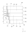
- Embodiment 2 A light source distribution element 100 and a headlamp module according to a second embodiment will be described based on FIGS. 11 to 18.
- the headlamp module according to Embodiment 2 is different from the headlamp module according to Embodiment 1 in that the joining surface of the entrance part 110 is divided into five joining surfaces from the first joining surface 111 to the fifth joining surface 115, and the collective light guide.
- the unit 120 is connected to the five first light guide parts 121 to the fifth light guide part 125, and the collective light collecting optical part 210 is connected to the five first light collecting optical parts 211 to the fifth light collecting optical part 215, and the collective light guide part 210 is connected to the five first light collecting optical parts 211 to the fifth light collecting optical part 215.
- the light section 200 is the five first light distribution sections 221 to the fifth light distribution section 225 and the projection section 230 is the five first projection lenses 231 to the fifth projection lenses 235
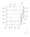
- the incident section 110 The three bonding surfaces are the first bonding surface 111, the second bonding surface 112, and the fourth bonding surface 114
- the collective light guide section 120 is the three first bonding surfaces 121, the second light guide section. 122, a fourth light guide section 124, a collective light collecting optical section 210, a first light collecting optical section 211, a second light collecting optical section 212, a fourth light collecting optical section 214, and a collective arrangement.
- the light section 200 includes three first light distribution sections 221, second light distribution section 222, and fourth light distribution section 224, and the projection section 230 includes three first projection lenses 231 and second projection lenses 232. , the difference is that a fourth projection lens 234 is used.
- the same reference numerals as those given in FIGS. 1 to 10 indicate the same or equivalent parts.
- the joining surface of the entrance part 110 is divided into two parts having the same length, that is, the same width, along the Z-axis direction, a first joining surface 111 located at the center, and a second joining surface 111 located at one end in one direction from the center. It has a joint surface 112 and a fourth joint surface 114 located on the other end side in one direction from the center.
- the collective light guide section 120 has a joint surface that joins the joint surface of the light source distribution element 100, and has three output surfaces arranged without overlapping in the Z-axis direction and the X-axis direction, that is, the first output surface 121a. , a second output surface 122a, and a fourth output surface 124a, and transmits light from the joint surface of the light source distribution element 100 to the first output surface 121a, the second output surface 122a, and the fourth output surface 124a.
- the length W in the X-axis direction of the first output surface 121a, the second output surface 122a, and the fourth output surface 124a is the same as that of the first output surface 121a, the second output surface 122a, and the fourth output surface 124a in the first embodiment. This is the same as the length W in the X-axis direction of each of the fourth output surfaces 124a.
- the collective light guide section 120 includes a first light guide section 121, a second light guide section 122, and a fourth light guide section 124.
- the light guide section 124 differs from the first light guide section 121, second light guide section 122, and fourth light guide section 124 in Embodiment 1 only in the length along the Z-axis direction. The same is true for this point.
- the apparent height of the light source can be reduced by dividing the light beam from the light source 1 into three parts, and The length of the side in the Z-axis direction of the output surface of the light guide section 120 can be reduced, and the length of the side in the Z-axis direction of each of the first output surface 121a, second output surface 122a, and fourth output surface 124a can be reduced. Can be made smaller.
- the light source distribution element 100 according to Embodiment 1 is applied to a headlamp module, the height of the projection surface can be reduced, and miniaturization can be achieved.
- the light distribution forming unit 200 directs the light from the first output surface 121a, the second output surface 122a, and the fourth output surface 124a of the light source distribution element 100 to the first projection surface 231a and the second projection surface 232a. and a fourth projection surface 234a, and the light is projected from the first projection surface 231a, the second projection surface 232a, and the fourth projection surface 234a.
- the first light collecting optical part 211, the second light collecting optical part 212, and the fourth light collecting optical part 214 of the collective light collecting optical part 210 in the light distribution forming part 200 are the same as the first light collecting optical part 214 in the first embodiment. This is the same as the condensing optical section 211, the second condensing optical section 212, and the fourth condensing optical section 214, respectively.
- the first light distribution section 221, the second light distribution section 222, and the fourth light distribution section 224 of the collective light distribution section 220 in the light distribution forming section 200 are the same as the first light distribution section 221 in the first embodiment. , the second light distribution section 222, and the fourth light distribution section 224, respectively.
- the first projection lens 231, second projection lens 232, and fourth projection lens 234 of the projection section 230 in the light distribution forming section 200 are the first projection lens 231, the second projection lens in Embodiment 1, respectively. 232 and the fourth projection lens 234, respectively.
- the light guided from the first joint surface 111 of the entrance section 110 to the first light guide section 121 is directed along the Y axis to the first output surface 121a, as shown as a light beam L1 in FIGS. 17 and 18.
- the light that travels straight and reaches the reflective surface of the first condensing optical section 211 is totally reflected and condensed forward and downward in the Z-axis direction by the reflective surface of the first condensing optical section 211.
- the light propagates within the light distribution section 221 and reaches the first projection lens 231 .
- the light that has reached the first projection lens 231 is focused by the first projection lens 231 and emitted forward as low beam irradiation light.
- the light guided from the second joint surface 112 of the incident section 110 to the second light guide section 122 is directed along the Y axis to the first reflective surface 122b, as shown as a light beam L2 in FIGS. 17 and 18.
- the light that travels straight and reaches the first reflective surface 122b is totally reflected by the first reflective surface 122b at right angles to one end side in the X-axis direction.
- the light that is totally reflected at right angles by the first reflective surface 122b and reaches the second reflective surface 122c is totally reflected at right angles by the second reflective surface 122c, and is directed to the second output surface 122a along the Y axis.
- the light is guided and reaches the reflective surface of the second condensing optical section 212.
- the light that has reached the reflective surface of the second condensing optical section 212 is totally reflected and condensed forward and downward in the Z-axis direction by the reflective surface of the second condensing optical section 212, and is condensed by the reflective surface of the second condensing optical section 212. 222 and reaches the second projection lens 232.
- the light that has reached the second projection lens 232 is focused by the second projection lens 232 and emitted forward as low beam irradiation light.
- the light guided from the fourth joint surface 114 of the incident section 110 to the fourth light guiding section 124 is directed along the Y axis to the fifth reflecting surface 124b, as shown as a light beam L4 in FIGS. 17 and 18.
- the light that travels straight and reaches the fifth reflective surface 124b is totally reflected by the fifth reflective surface 124b at a right angle toward the other end in the X-axis direction.
- the light that is totally reflected at right angles by the fifth reflecting surface 124b and reaches the sixth reflecting surface 124c is totally reflected at right angles by the sixth reflecting surface 124c and travels along the Y-axis to the fourth output surface 124a.
- the light is guided and reaches the reflective surface of the fourth condensing optical section 214.
- the light reaching the reflective surface of the fourth condensing optical section 214 is totally reflected and condensed forward and downward in the Z-axis direction by the reflective surface of the fourth condensing optical section 214, and is then condensed into the fourth light distribution section. 224 and reaches the fourth projection lens 234.
- the light that has reached the fourth projection lens 234 is focused by the fourth projection lens 234 and emitted forward as low beam irradiation light.
- the light source distribution element 100 directs the incident light beam incident from the incidence section 110 to the first light guide section 121, the second light guide section 122, and the fourth light guide section. 124, by dividing into three parts in one direction and branching, the dividing direction is determined with respect to the first joint surface 111, the second joint surface 112, and the fourth joint surface 114, which are the light emission reference planes. In other words, the apparent size of the light source in one direction can be reduced. Therefore, the structure can be simplified and made thinner without deteriorating the light utilization efficiency.
- the headlamp module according to the second embodiment applies the light source distribution element 100 described above, and the light distribution forming section 200 allows the first projection lens 231 located along the other direction, the second projection lens 231 located along the other direction Since light is projected from the lens 232 and the fourth projection lens 234, the direction perpendicular to the plane defined by one direction and the other direction in the first projection lens 231, the second projection lens 232, and the fourth projection lens 234, In other words, the length in the height direction can be reduced, the structure can be simplified, and the thickness can be reduced in the height direction without reducing the light utilization efficiency.
- the joint surface of the entrance section 110 is divided into five, and the light from the five divided joint surfaces 111 to 115 of the entrance section 110 is transmitted to the five exit surfaces 121a of the light source distribution element 100.
- 125a propagates the light from the five output surfaces 121a to 125a of the light source distribution element 100 to the light distribution forming section 200, and projects the light from the five projection surfaces 231a to 235a according to the second embodiment.
- the joining surface of the entrance section 110 is divided into three, and the light from the three divided joining surfaces 111, 112, 114 of the entrance section 110 is transmitted to the three exit surfaces 121a, 122a, 124a of the light source distribution element 100.
- the headlight module has been shown in which light from the three output surfaces 121a, 122a, and 124a in the light source distribution element 100 is propagated to the light distribution forming section 200 and projected from the three projection surfaces 231a, 232a, and 234a.
- the joint surface of the entrance section 110 is divided into four or seven parts, and the light source distribution element 100 and the light distribution forming section are divided into four parts or seven parts, and the light source distribution element 100 and the light distribution forming part are divided into four parts or seven parts, and the light source distribution element 100 and the light distribution forming part 200 may be used.
- the joint surface of the entrance part 110 is divided into an odd number of three or more, the first light guide section is arranged on the joint surface located in the center, and the remaining Half of the light guide parts are arranged in the Z-axis direction, half of the light guide parts arranged on one end side of the Z-axis direction are tilted toward one end side of the X-axis direction, and half of the light guide parts arranged on the other end side of the Z-axis direction are tilted. It is preferable that the light guide section is tilted toward the other end in the X-axis direction. In this case, since the light flux from the lens 116 can be concentrated on the cemented surface located at the center of the entrance section 110, it becomes easy to form a light distribution from the projection surface.
- Embodiment 3 A light source distribution element 100 and a headlamp module according to Embodiment 3 will be explained based on FIGS. 19 to 26.
- the headlight module according to the third embodiment is different from the headlight module according to the first embodiment in that the lengths in the X-axis direction from the first output surface 121a to the fifth output surface 125a are all W.
- the length of the first output surface 121a in the X-axis direction is W
- the length of the second output surface 122a and the fourth output surface 124a in the X-axis direction is shorter than W1
- the third output surface The difference is that the length of the surface 123a and the fifth output surface 125a in the X-axis direction is W2 , which is shorter than W1 .
- the distance between the pair of reflective surfaces in the second light guide section 122 and the fourth light guide section 124, the length of the second light condensing optical section 212 and the fourth light condensing optical section 214 in the X-axis direction The lengths of the second light distribution section 222 and the fourth light distribution section 224 in the X-axis direction, and the lengths of the second projection lens 232 and the fourth projection lens 234 in the X-axis direction are W 1 , the distance between the pair of reflective surfaces in the third light guide section 123 and the fifth light guide section 125, the length of the third light condensing optical section 213 and the fifth light condensing optical section 215 in the X-axis direction, The lengths of the third light distribution section 223 and the fifth light distribution section 225 in the X-axis direction and the lengths of the third projection lens 233 and the fifth projection lens 235 in the X-axis direction are different at W2. . The other points are the same. The relationship between W,
- the lengths in the X-axis direction of the second output surface 122a, the second light guide section 122, the second condensing optical section 212, the second light distribution section 222, and the second projection lens 232 and the fourth The lengths of the output surface 124a, the fourth light guide section 124, the fourth condensing optical section 214, the fourth light distribution section 224, and the fourth projection lens 234 in the X-axis direction may be different.
- the lengths in the X-axis direction and the The lengths of the fifth light emitting surface 125a, the fifth light guiding section 125, the fifth condensing optical section 215, the fifth light distribution section 225, and the fifth projection lens 235 in the X-axis direction may be different.
- the same reference numerals as those in FIGS. 1 to 10 indicate the same or equivalent parts.
- the first light guide section 121 is the same as the first light guide section 121 in the first embodiment.
- the opposing surface on one end side in the X-axis direction of the pair of opposing surfaces in the second light guide section 122 extends from the bottom surface in contact with the second bonding surface 112 of the incident section 110 to the second surface perpendicular to the second bonding surface 112. It has a second reflecting surface 122c that is inclined at 45 degrees toward one end with respect to the second bonding surface 112 from the upper side of the second rising surface 122d to the second exit surface 122a.
- the distance between the first reflective surface 122b and the second reflective surface 122c along the X-axis direction is W1 , which is the same as the distance W1 between the second output surface 122a along the X-axis direction.
- the length from the bottom to the top of the second rising surface 122d corresponds to the length for obtaining the offset amount (W ⁇ W 1 ) with respect to the length W 1 of the second exit surface 122a in the X-axis direction.
- the amount of light totally reflected by the second reflecting surface 122c of the light totally reflected by the first reflecting surface 122b is determined by In this case, since there is no light from the second bonding surface 112 of the incident part 110, it is comparable to the case where the second rising surface 122d is not provided.
- the opposing surface on one end side in the X-axis direction of the pair of opposing surfaces in the third light guide section 123 extends from the bottom surface in contact with the third bonding surface 113 of the incident section 110 to the fourth surface perpendicular to the third bonding surface 113. It has a fourth reflecting surface 123c that is inclined at 45 degrees toward one end with respect to the third joint surface 113 from the upper side of the fourth rising surface 123d to the third output surface 123a.
- the distance between the third reflective surface 123b and the fourth reflective surface 123c along the X-axis direction is (W 1 +W 2 ).
- the distance W 2 of the third output surface 123a along the X-axis direction is the distance between the third reflection surface 123b and the fourth reflection surface 123c along the X-axis direction (W 1 +W 2 ) to the second This is the value obtained by subtracting the distance W 1 between the first reflective surface 122b and the second reflective surface 122c in the light guide section 122 along the X-axis direction.
- the distance (W 1 +W 2 ) between the third reflective surface 123b and the fourth reflective surface 123c of the third light guide 123 along the X-axis direction is equal to the first reflection of the second light guide 122. It is shorter than 2W1 , which is twice the distance W1 between the surface 122b and the second reflective surface 122c along the X-axis direction.
- the length from the bottom to the top of the fourth rising surface 123d is the offset amount (W-W 2 ) with respect to the length W 2 of the third exit surface 123a in the X-axis direction, in other words, (2W-(W 1 +W 2 ) Corresponds to the length to obtain ).
- the amount of light totally reflected by the fourth reflective surface 123c of the light totally reflected by the third reflective surface 123b is determined by In this case, since there is no light from the third bonding surface 113 of the incident part 110, it is comparable to the case where the fourth rising surface 123d is not provided.
- the opposing surface on the other end side in the X-axis direction of the pair of opposing surfaces in the fourth light guide section 124 extends from the bottom surface in contact with the fourth bonding surface 114 of the incident section 110 to the bottom surface perpendicular to the fourth bonding surface 114. 6, and has a sixth reflecting surface 124c that is inclined at 45 degrees toward the other end with respect to the fourth joint surface 114 from the upper side of the sixth rising surface 124d to the fourth output surface 124a.
- the distance between the fifth reflective surface 124b and the sixth reflective surface 124c along the X-axis direction is W1 , which is the same as the distance W1 between the fourth output surface 124a along the X-axis direction.
- the length from the bottom to the top of the sixth rising surface 124d corresponds to the length for obtaining the offset amount (W-W 1 ) with respect to the length W 1 of the fourth exit surface 124a in the X-axis direction.
- the amount of light totally reflected by the sixth reflective surface 124c of the light totally reflected by the fifth reflective surface 124b is determined by In this case, since there is no light from the fourth bonding surface 114 of the incident part 110, it is comparable to the case where the sixth rising surface 124d is not provided.
- the opposing surface on the other end side in the X-axis direction of the pair of opposing surfaces in the fifth light guide section 125 extends from the bottom surface in contact with the fifth bonding surface 115 of the incident section 110 to the plane perpendicular to the fifth bonding surface 115.
- the eighth reflecting surface 125c is inclined at 45 degrees toward the other end with respect to the fifth joint surface 115 from the upper side of the eighth rising surface 125d to the fifth output surface 125a.
- the distance between the seventh reflective surface 125b and the eighth reflective surface 125c along the X-axis direction is (W 1 +W 2 ).
- the distance W 2 of the fifth output surface 125a along the X-axis direction is the distance W 2 between the seventh reflective surface 125b and the eighth reflective surface 125c along the X-axis direction (W 1 +W 2 ) to the fourth This is the value obtained by subtracting the distance W 1 between the fifth reflective surface 124b and the sixth reflective surface 124c in the light guide section 124 along the X-axis direction.
- the distance (W 1 +W 2 ) between the seventh reflective surface 125b and the eighth reflective surface 125c of the fifth light guiding section 125 along the X-axis direction is equal to It is shorter than twice 2W1 of the distance W1 between the surface 124b and the sixth reflective surface 124c along the X-axis direction.
- the length from the bottom to the top of the eighth rising surface 125d is the offset amount (W-W 2 ) with respect to the length W 2 of the fifth exit surface 125a in the X-axis direction, in other words, (2W-(W 1 +W 2 ) Corresponds to the length to obtain ).
- the amount of light totally reflected by the eighth reflective surface 125c of the light totally reflected by the seventh reflective surface 125b is determined by In this case, since there is no light from the fifth bonding surface 115 of the incident part 110, it is comparable to the case where the eighth rising surface 125d is not provided.
- the total length in the X-axis direction from the first output surface 121a to the fifth output surface 125a is 5W ⁇ ((W+2( W 1 +W 2 ))), that is, 4W-2 (W 1 +W 2 ) shorter.
- the light distribution forming section 200 is the same as the light distribution forming section 200 in the first embodiment, except for the length in the X-axis direction.
- the first condensing optical section 211 is the same as the first condensing optical section 211 in the first embodiment.
- the length of the second condensing optical part 212 and the fourth condensing optical part 214 in the X-axis direction is W1
- the length of the second condensing optical part 212 and the fourth condensing optical part 214 in the X-axis direction is The distance along the line W is the same as 1 .
- the lengths of the second light distribution section 222 and the fourth light distribution section 224 in the X-axis direction are each W1 , and the lengths of the second light distribution section 222 and the fourth light distribution section 224 in the X-axis direction are The interval W is the same as 1 .
- the lengths of the second projection lens 232 and the fourth projection lens 234 in the X-axis direction are each W 1 , and the interval W along the X-axis direction between the second exit surface 122a and the fourth exit surface 124a, respectively. Same as 1 .
- the length of the third condensing optical part 213 and the fifth condensing optical part 215 in the X-axis direction is W2, and the length of the third condensing optical part 213 and the fifth condensing optical part 215 in the X-axis direction is W 2 .
- the distance along the line is the same as W2 .
- the lengths of the third light distribution section 223 and the fifth light distribution section 225 in the X-axis direction are each W2
- the lengths of the third light distribution section 223 and the fifth light distribution section 225 in the X-axis direction are respectively W2. It is the same as the interval W2 .
- the lengths of the third projection lens 233 and the fifth projection lens 235 in the X-axis direction are each W2 , and the distance W between the third exit surface 123a and the fifth exit surface 125a along the X-axis direction. Same as 2 .
- the total length in the X-axis direction from the first projection surface 231a to the fifth projection surface 235a arranged in a line along the X-axis (W+2(W 1 +W 2 )) is the sum of all lengths W. It becomes 4W-2 (W 1 +W 2 ) shorter than 5W.
- the light source distribution element 100 according to the third embodiment has the same effects as the light source distribution element 100 according to the first embodiment, and also can shorten the length in the X-axis direction, simplify the structure, and It can be made shorter in the width direction and thinner without reducing usage efficiency.
- the headlamp module according to the third embodiment includes the light source distribution element 100 and the light distribution forming section 200 described above, so that the structure is simplified, the light utilization efficiency is not reduced, and the width direction is short. , it can be made thinner in the height direction.
- Embodiment 4 A headlamp module according to Embodiment 4 will be described based on FIGS. 27 to 32.
- the headlamp module according to the fourth embodiment is different from the headlamp module according to the third embodiment in that a cut-off line forming surface 220a is provided in the collective light distribution section 220 in the light distribution forming section 200. .
- FIGS. 27 to 32 the same reference numerals as those used in FIGS. 1 to 10 and FIGS. 19 to 26 indicate the same or equivalent parts.
- the components of the light distribution forming section 200 other than the collective light distribution section 220 are basically the same as the headlamp module according to the third embodiment, so the description will focus on the collective light distribution section 220.
- the collective light distribution section 220 has a cut-off line forming surface 220a having a ridge line for forming a cut-off line along the X-axis direction on the bottom surface, that is, a surface located on the incident section 110 side in the Y-axis direction.
- the area from the ridgeline of the offline forming surface 220a to the front surface of the collective condensing optical part 210 is the first area part 220A, and the area from the ridgeline of the cutoff line forming surface 220a to the projection part 230 is the second area part 220B.
- the bottom surface is a horizontal surface along the ZX plane, and the top surface opposite to the bottom surface is also a horizontal surface along the ZX plane.
- the bottom surface is a surface that slopes toward the Z-axis direction with respect to the Z-X plane
- the top surface is also a surface that slopes toward the Z-axis direction with respect to the Z-X plane. good.
- at least one of the bottom surface and the top surface may be changed to a surface parallel to the ZX plane.
- a reflective surface is provided on the bottom surface of the first region portion 220A.
- the collective light distribution section 220 totally reflects the light from the front surface of the collective light condensing optical section 210 by a cutoff line forming surface 220a which is a reflective surface in the first area section 220A, and transmits the light with a cutoff line formed therein to the first area.
- the light is propagated to the projection unit 230 via the second area 220B.
- the bottom surface and the top surface of the second region section 220B are also horizontal surfaces along the Z-X plane like the bottom surface and the top surface of the first region section 220A, but the bottom surface and the top surface of the second region section 220B are horizontal planes along the Z-X plane. It may be a surface with an inclination or a surface parallel to the ZX plane.
- the first light distribution section 221 constituting the collective light distribution section 220 has a first cutoff line forming surface 221a having a ridgeline for forming a cutoff line along the X-axis direction.
- the area from the ridgeline of the first cut-off line forming surface 221a to the front surface of the first condensing optical section 211 is the first area portion 221A
- the area from the ridge line of the first cut-off line forming surface 221a to the first projection lens 231 is the first area portion 221A.
- the bottom surface is a surface located on the incident section 110 side, and is a horizontal surface along the ZX plane.
- the upper surface is also a horizontal plane along the ZX plane.
- a first cut-off line forming surface 221a which is a reflective surface, is provided on the bottom surface of the first region portion 221A.
- the length in the X-axis direction that is, the interval between the pair of opposing surfaces facing each other parallel to the X-axis direction is W.
- a portion of the light beam L1 from the front surface of the first condensing optical section 211 is reflected by the first cut-off line forming surface 221a.
- the light reflected by the first cutoff line forming surface 221a and on which the cutoff line has been formed is guided to the first projection lens 231 via the second region portion 221B.
- the other light of the luminous flux L1 from the front surface of the first condensing optical section 211 is not reflected by the first cut-off line forming surface 221a, and is transmitted to the first projection via the second region section 221B. It is guided directly to the lens 231.
- the light reflected by the first cut-off line forming surface 221a and the light not reflected by the first cut-off line forming surface 221a are combined, a cut-off light distribution is formed, and a low beam is emitted from the first projection lens 231. Projected.
- the second light distribution section 222 constituting the collective light distribution section 220 has a second cutoff line forming surface 222a having a ridgeline for forming a cutoff line along the X-axis direction.
- the area from the ridgeline of the second cut-off line forming surface 222a to the front surface of the second condensing optical section 212 is the first area portion 222A
- the area from the ridge line of the second cut-off line forming surface 222a to the second projection lens 232 is the first area portion 222A.
- the bottom surface is a surface located on the incident section 110 side, and is a horizontal surface along the ZX plane.
- the upper surface is also a horizontal plane along the ZX plane.
- a second cut-off line forming surface 222a which is a reflective surface, is provided on the bottom surface of the first region portion 222A.
- the length in the X-axis direction that is, the interval between the pair of opposing surfaces facing each other parallel to the X-axis direction is W.
- a portion of the light beam L2 from the front surface of the second condensing optical section 212 is reflected by the second cut-off line forming surface 222a.
- the light reflected by the second cutoff line forming surface 222a and on which the cutoff line has been formed is guided to the second projection lens 232 via the second region portion 222B.
- the other light of the luminous flux L2 from the front surface of the second condensing optical section 212 is not reflected by the second cut-off line forming surface 222a and is transmitted to the second projection via the second region section 222B. It is guided directly to lens 232.
- the light reflected by the second cut-off line forming surface 222a and the light not reflected by the first cut-off line forming surface 222a are combined, a cut-off light distribution is formed, and a low beam is emitted from the second projection lens 232. Projected.
- the third light distribution section 223 constituting the collective light distribution section 220 has a third cutoff line forming surface 223a having a ridgeline for forming a cutoff line along the X-axis direction.
- the area from the ridgeline of the third cut-off line forming surface 223a to the front surface of the third condensing optical section 213 is the first area portion 223A
- the area from the ridge line of the third cut-off line forming surface 223a to the third projection lens 233 is the first area portion 223A.
- the bottom surface is a surface located on the incident section 110 side, and is a horizontal surface along the ZX plane.
- the upper surface is also a horizontal plane along the ZX plane.
- a third cut-off line forming surface 223a which is a reflective surface, is provided on the bottom surface of the first region portion 223A.
- the length in the X-axis direction that is, the interval between the pair of opposing surfaces facing each other parallel to the X-axis direction is W.
- a portion of the light beam L3 from the front surface of the third condensing optical section 213 is reflected by the third cut-off line forming surface 223a.
- the light reflected by the first cutoff line forming surface 223a and on which the cutoff line has been formed is guided to the third projection lens 233 via the second region section 223B.
- the other light of the luminous flux L3 from the front surface of the third condensing optical section 213 is not reflected by the third cut-off line forming surface 223a and is transmitted to the second projection via the second region section 223B. It is guided directly to lens 232.
- the light reflected by the third cut-off line forming surface 223a and the light not reflected by the third cut-off line forming surface 223a are combined, a cut-off light distribution is formed, and a low beam is emitted from the second projection lens 232. Projected.
- the fourth light distribution section 224 constituting the collective light distribution section 220 has a fourth cutoff line forming surface 224a having a ridgeline for forming a cutoff line along the X-axis direction.
- the area from the ridgeline of the fourth cut-off line forming surface 224a to the front surface of the fourth condensing optical unit 214 is the first area portion 224A
- the area from the ridge line of the fourth cut-off line forming surface 224a to the fourth projection lens 234 is the first area portion 224A.
- the bottom surface is a surface located on the incident section 110 side, and is a horizontal surface along the ZX plane.
- the upper surface is also a horizontal plane along the ZX plane.
- a fourth cut-off line forming surface 224a which is a reflective surface, is provided on the bottom surface of the first region portion 224A.
- the length in the X-axis direction that is, the interval between the pair of opposing surfaces facing each other parallel to the X-axis direction is W.
- a portion of the light beam L4 from the front surface of the fourth condensing optical unit 214 is reflected by the fourth cut-off line forming surface 224a.
- the light reflected by the fourth cutoff line forming surface 224a and on which the cutoff line has been formed is guided to the fourth projection lens 234 via the second area portion 224B.
- the other light of the luminous flux L4 from the front surface of the fourth condensing optical section 214 is not reflected by the fourth cut-off line forming surface 224a and is projected into the fourth projection via the second region section 224B. is directed directly to lens 234.
- the light reflected by the fourth cut-off line forming surface 224a and the light not reflected by the fourth cut-off line forming surface 224a are combined, a cut-off light distribution is formed, and a low beam is emitted from the fourth projection lens 234. Projected.
- the fifth light distribution section 225 constituting the collective light distribution section 220 has a fifth cutoff line forming surface 225a having a ridgeline for forming a cutoff line along the X-axis direction.
- the area from the ridge line of the fifth cut-off line forming surface 225a to the front surface of the fifth condensing optical unit 215 is the first area portion 225A
- the area from the ridge line of the fifth cut-off line forming surface 225a to the fifth projection lens 235 is the first area portion 225A.
- the bottom surface is a surface located on the incident section 110 side, and is a horizontal surface along the ZX plane.
- the upper surface is also a horizontal plane along the ZX plane.
- a fifth cutoff line forming surface 225a which is a reflective surface, is provided on the bottom surface of the first region portion 225A.
- the length in the X-axis direction that is, the interval between the pair of opposing surfaces facing each other parallel to the X-axis direction is W.
- a portion of the light beam L5 from the front surface of the fifth condensing optical section 215 is reflected by the fifth cut-off line forming surface 225a.
- the light reflected by the fifth cutoff line forming surface 225a and on which the cutoff line has been formed is guided to the fifth projection lens 235 via the second region portion 225B.
- the other light of the luminous flux L5 from the front surface of the fifth condensing optical section 215 is not reflected by the fifth cut-off line forming surface 225a and is projected into the fifth projection via the second region section 225B. It is guided directly to lens 235.
- the light reflected by the fifth cut-off line forming surface 225a and the light not reflected by the fifth cut-off line forming surface 225a are combined, a cut-off light distribution is formed, and a low beam is output from the fifth projection lens 235. Projected.
- the ridge lines for forming the cut-off lines from the first cut-off line forming surface 221a to the fifth cut-off line forming surface 225a are the junctions of the first region portions 221A to 225A and the second region portions 221B to 225B, respectively. This is the underline on the surface, that is, the front edge of the reflective surface of the bottom surface of each of the first regions 221A to 225A.
- the ridge line for forming the cut-off line is positioned so that the upper side, that is, the outside of the light distribution pattern, is dark, and the lower side, that is, the inside of the light distribution pattern, is bright.
- the headlamp module according to Embodiment 4 configured as described above has the same effects as the headlamp module according to Embodiment 3, and also has a cutoff for collective light distribution section 220 to form a cutoff line. Since the off-line forming surface 220a is provided, the light projected from the projection unit 230 can be projected forward as low beam irradiation light, which is light with a light distribution pattern having a cut-off line. In addition, by changing the shape of the ridgeline for forming the cutoff line of each of the cutoff line forming surfaces 221a to 225a of the first light distribution section 221 to the fifth light distribution section 225, a desired cutoff line shape can be obtained. It is possible to obtain a light distribution pattern having the following characteristics.
- the cutoff line forming surfaces 221a to 225a, the first area portions 221A to 225A, and the second region portions 221B to 225B are given uniqueness, they may be formed into continuous cutoff line forming surfaces in the X-axis direction. That is, the cut-off line forming surfaces 221a to 225a are all rectangular shapes located on the same plane and without any difference in level.
- the first light distribution section 221 in the first and second embodiments each has the cut-off line forming surfaces 221a to 225a of the fourth embodiment.
- 221A may be replaced with a fifth light distribution section 225A. Thereby, a light distribution pattern having a desired cut-off line shape can be obtained.
- the light source distribution element for a headlamp device and the headlamp module according to the present disclosure are suitable for use in headlight devices for automobiles and motorcycles, particularly low beam headlights.
- Light source 100 Light source distribution element for headlamp device, 110 Incident part, 111 First joint surface, 112 Second joint surface, 113 Third joint surface, 114 Fourth joint surface, 115 Fifth joint surface, 120 collective light guide section, 121 first light guide section, 122 second light guide section, 123 third light guide section, 124 fourth light guide section, 125 fifth light guide section, 121a th 1 exit surface, 122a 2nd exit surface, 123a 3rd exit surface, 124a 4th exit surface, 125a 5th exit surface, 122b 1st reflective surface, 122c 2nd reflective surface, 123b 3rd reflective surface, 123c fourth reflective surface, 124b fifth reflective surface, 124c sixth reflective surface, 125b seventh reflective surface, 125c eighth reflective surface, 200 light distribution forming section, 210 collective converging optics Part, 211 First condensing optical section, 212 Second condensing optical section, 213 Third condensing optical section, 214 Fourth condensing optical section, 215 Fifth condens
Landscapes
- Engineering & Computer Science (AREA)
- General Engineering & Computer Science (AREA)
- Non-Portable Lighting Devices Or Systems Thereof (AREA)
Priority Applications (2)
| Application Number | Priority Date | Filing Date | Title |
|---|---|---|---|
| PCT/JP2022/032476 WO2024047719A1 (ja) | 2022-08-30 | 2022-08-30 | 前照灯装置用光源分配素子及び前照灯モジュール |
| JP2024543627A JP7766813B2 (ja) | 2022-08-30 | 2022-08-30 | 前照灯装置用光源分配素子及び前照灯モジュール |
Applications Claiming Priority (1)
| Application Number | Priority Date | Filing Date | Title |
|---|---|---|---|
| PCT/JP2022/032476 WO2024047719A1 (ja) | 2022-08-30 | 2022-08-30 | 前照灯装置用光源分配素子及び前照灯モジュール |
Publications (1)
| Publication Number | Publication Date |
|---|---|
| WO2024047719A1 true WO2024047719A1 (ja) | 2024-03-07 |
Family
ID=90099199
Family Applications (1)
| Application Number | Title | Priority Date | Filing Date |
|---|---|---|---|
| PCT/JP2022/032476 Ceased WO2024047719A1 (ja) | 2022-08-30 | 2022-08-30 | 前照灯装置用光源分配素子及び前照灯モジュール |
Country Status (2)
| Country | Link |
|---|---|
| JP (1) | JP7766813B2 (https=) |
| WO (1) | WO2024047719A1 (https=) |
Cited By (1)
| Publication number | Priority date | Publication date | Assignee | Title |
|---|---|---|---|---|
| WO2025263257A1 (ja) * | 2024-06-19 | 2025-12-26 | 株式会社小糸製作所 | 車両用前照灯の光源モジュール |
Citations (2)
| Publication number | Priority date | Publication date | Assignee | Title |
|---|---|---|---|---|
| JP2016181364A (ja) * | 2015-03-24 | 2016-10-13 | スタンレー電気株式会社 | 車両用灯具 |
| JP7031087B1 (ja) * | 2021-05-12 | 2022-03-07 | 三菱電機株式会社 | 前照灯装置用光源分配素子、前照灯装置、及び前照灯モジュール |
-
2022
- 2022-08-30 JP JP2024543627A patent/JP7766813B2/ja active Active
- 2022-08-30 WO PCT/JP2022/032476 patent/WO2024047719A1/ja not_active Ceased
Patent Citations (2)
| Publication number | Priority date | Publication date | Assignee | Title |
|---|---|---|---|---|
| JP2016181364A (ja) * | 2015-03-24 | 2016-10-13 | スタンレー電気株式会社 | 車両用灯具 |
| JP7031087B1 (ja) * | 2021-05-12 | 2022-03-07 | 三菱電機株式会社 | 前照灯装置用光源分配素子、前照灯装置、及び前照灯モジュール |
Cited By (1)
| Publication number | Priority date | Publication date | Assignee | Title |
|---|---|---|---|---|
| WO2025263257A1 (ja) * | 2024-06-19 | 2025-12-26 | 株式会社小糸製作所 | 車両用前照灯の光源モジュール |
Also Published As
| Publication number | Publication date |
|---|---|
| JP7766813B2 (ja) | 2025-11-10 |
| JPWO2024047719A1 (https=) | 2024-03-07 |
Similar Documents
| Publication | Publication Date | Title |
|---|---|---|
| KR102703973B1 (ko) | 하이빔과 로우빔이 통합된 차량용 램프 조명 장치, 차량용 램프 및 차량 | |
| JP6383043B2 (ja) | 前照灯モジュール | |
| JP7675673B2 (ja) | 前照灯装置用光源分配素子、前照灯装置、及び前照灯モジュール | |
| JP6188879B2 (ja) | 前照灯モジュール及び前照灯装置 | |
| CN103890484B (zh) | 用于车辆前灯的前灯透镜和车辆前灯 | |
| EP2105655B1 (en) | Vehicle lamp | |
| JP6324635B2 (ja) | 前照灯モジュール及び前照灯装置 | |
| CN112469941A (zh) | 前灯装置 | |
| CN112781001B (zh) | 车灯光学元件、车灯模组和车辆 | |
| US12055279B2 (en) | Headlight device module including a condensing optical unit and a light guide member with cuttoff-lines forming parts | |
| EP2503224B1 (en) | Vehicle lighting unit | |
| JP7109681B2 (ja) | 前照灯モジュール及び前照灯装置 | |
| JP6688153B2 (ja) | レンズ体および車両用灯具 | |
| JP2017112107A (ja) | レンズ体および車両用灯具 | |
| JP2018181635A (ja) | レンズ体および車両用灯具 | |
| JP7766813B2 (ja) | 前照灯装置用光源分配素子及び前照灯モジュール | |
| JP7766812B2 (ja) | 前照灯モジュール | |
| JP6682378B2 (ja) | レンズ体、レンズ結合体及び車両用灯具 | |
| JP7826631B2 (ja) | 車両用前照灯モジュール、及び車両用前照灯ユニット | |
| CN213810430U (zh) | 聚光器、车辆前照灯模组、车灯及车辆 | |
| CN220817517U (zh) | 一种车灯光学元件、车灯模组和车辆 | |
| WO2023218624A1 (ja) | 前照灯装置 | |
| CN119532654A (zh) | 一种前照灯组件 | |
| CN117346099A (zh) | 一种车灯光学元件、车灯模组和车辆 | |
| CN113280302A (zh) | 聚光器、车辆前照灯模组、车灯及车辆 |
Legal Events
| Date | Code | Title | Description |
|---|---|---|---|
| 121 | Ep: the epo has been informed by wipo that ep was designated in this application |
Ref document number: 22957323 Country of ref document: EP Kind code of ref document: A1 |
|
| ENP | Entry into the national phase |
Ref document number: 2024543627 Country of ref document: JP Kind code of ref document: A |
|
| NENP | Non-entry into the national phase |
Ref country code: DE |
|
| 122 | Ep: pct application non-entry in european phase |
Ref document number: 22957323 Country of ref document: EP Kind code of ref document: A1 |