WO2024047701A1 - 電気泳動装置とキャピラリアレイ - Google Patents
電気泳動装置とキャピラリアレイ Download PDFInfo
- Publication number
- WO2024047701A1 WO2024047701A1 PCT/JP2022/032425 JP2022032425W WO2024047701A1 WO 2024047701 A1 WO2024047701 A1 WO 2024047701A1 JP 2022032425 W JP2022032425 W JP 2022032425W WO 2024047701 A1 WO2024047701 A1 WO 2024047701A1
- Authority
- WO
- WIPO (PCT)
- Prior art keywords
- excitation light
- capillary array
- fluorescence
- capillary
- electrophoresis
- Prior art date
- Legal status (The legal status is an assumption and is not a legal conclusion. Google has not performed a legal analysis and makes no representation as to the accuracy of the status listed.)
- Ceased
Links
Images







Classifications
-
- G—PHYSICS
- G01—MEASURING; TESTING
- G01N—INVESTIGATING OR ANALYSING MATERIALS BY DETERMINING THEIR CHEMICAL OR PHYSICAL PROPERTIES
- G01N27/00—Investigating or analysing materials by the use of electric, electrochemical, or magnetic means
- G01N27/26—Investigating or analysing materials by the use of electric, electrochemical, or magnetic means by investigating electrochemical variables; by using electrolysis or electrophoresis
- G01N27/416—Systems
- G01N27/447—Systems using electrophoresis
-
- G—PHYSICS
- G01—MEASURING; TESTING
- G01N—INVESTIGATING OR ANALYSING MATERIALS BY DETERMINING THEIR CHEMICAL OR PHYSICAL PROPERTIES
- G01N27/00—Investigating or analysing materials by the use of electric, electrochemical, or magnetic means
- G01N27/26—Investigating or analysing materials by the use of electric, electrochemical, or magnetic means by investigating electrochemical variables; by using electrolysis or electrophoresis
- G01N27/416—Systems
- G01N27/447—Systems using electrophoresis
- G01N27/44704—Details; Accessories
- G01N27/44717—Arrangements for investigating the separated zones, e.g. localising zones
- G01N27/44721—Arrangements for investigating the separated zones, e.g. localising zones by optical means
-
- G—PHYSICS
- G01—MEASURING; TESTING
- G01N—INVESTIGATING OR ANALYSING MATERIALS BY DETERMINING THEIR CHEMICAL OR PHYSICAL PROPERTIES
- G01N21/00—Investigating or analysing materials by the use of optical means, i.e. using sub-millimetre waves, infrared, visible or ultraviolet light
- G01N21/62—Systems in which the material investigated is excited whereby it emits light or causes a change in wavelength of the incident light
- G01N21/63—Systems in which the material investigated is excited whereby it emits light or causes a change in wavelength of the incident light optically excited
- G01N21/64—Fluorescence; Phosphorescence
- G01N21/6486—Measuring fluorescence of biological material, e.g. DNA, RNA, cells
-
- G—PHYSICS
- G01—MEASURING; TESTING
- G01N—INVESTIGATING OR ANALYSING MATERIALS BY DETERMINING THEIR CHEMICAL OR PHYSICAL PROPERTIES
- G01N27/00—Investigating or analysing materials by the use of electric, electrochemical, or magnetic means
- G01N27/26—Investigating or analysing materials by the use of electric, electrochemical, or magnetic means by investigating electrochemical variables; by using electrolysis or electrophoresis
- G01N27/416—Systems
- G01N27/447—Systems using electrophoresis
- G01N27/44704—Details; Accessories
-
- G—PHYSICS
- G01—MEASURING; TESTING
- G01N—INVESTIGATING OR ANALYSING MATERIALS BY DETERMINING THEIR CHEMICAL OR PHYSICAL PROPERTIES
- G01N21/00—Investigating or analysing materials by the use of optical means, i.e. using sub-millimetre waves, infrared, visible or ultraviolet light
- G01N21/01—Arrangements or apparatus for facilitating the optical investigation
- G01N21/03—Cuvette constructions
- G01N2021/0346—Capillary cells; Microcells
-
- G—PHYSICS
- G01—MEASURING; TESTING
- G01N—INVESTIGATING OR ANALYSING MATERIALS BY DETERMINING THEIR CHEMICAL OR PHYSICAL PROPERTIES
- G01N21/00—Investigating or analysing materials by the use of optical means, i.e. using sub-millimetre waves, infrared, visible or ultraviolet light
- G01N21/62—Systems in which the material investigated is excited whereby it emits light or causes a change in wavelength of the incident light
- G01N21/63—Systems in which the material investigated is excited whereby it emits light or causes a change in wavelength of the incident light optically excited
- G01N21/64—Fluorescence; Phosphorescence
- G01N21/645—Specially adapted constructive features of fluorimeters
- G01N2021/6463—Optics
Definitions
- the present invention relates to an electrophoresis device that separates and analyzes samples such as DNA, and a capillary array that is attached to the electrophoresis device.
- An electrophoresis device is a device that separates a fluorescently labeled sample by electrophoresis and analyzes the sample by detecting fluorescence induced by irradiation with excitation light. Particularly when analyzing a trace amount of a sample such as DNA, a sample filled with a separation medium in a quartz glass capillary is separated by electrophoresis. Furthermore, in order to simultaneously analyze a plurality of samples, excitation light may be irradiated onto a capillary array in which capillaries are arranged in a planar manner along the arrangement direction.
- the excitation light is dispersed and reflected due to the difference in refractive index between the two, so the excitation light that passes through the capillary array is attenuated exponentially, and the fluorescence emitted by the sample is also reduced.
- Patent Document 1 discloses that in order to suppress the attenuation of excitation light transmitted through a capillary array, a liquid or solid whose refractive index is greater than air but not greater than water is placed in the space between the capillaries through which the excitation light passes. Disclosed is an intervening light transmission medium that is .
- Patent Document 1 does not give sufficient consideration to foreign substances that exist around the area where the excitation light is irradiated.
- Raman scattered light emitted from the light transmission medium interposed between the capillaries becomes a noise signal with respect to the fluorescence emitted by the sample, increasing the sensitivity limit and making it impossible to detect a small amount of fluorescence from the sample.
- Fluorescence emitted from floating dust in the atmosphere that is attracted to the charged capillary during electrophoresis also becomes a noise signal.
- the adhesive used to fix the capillary flows into the excitation light irradiation section, the fluorescence emitted from the adhesive becomes a noise signal.
- an object of the present invention to provide an electrophoresis device and a capillary array that can reduce noise signals caused by foreign matter around the excitation light irradiation part of the capillary array.
- the present invention provides a capillary array in which capillaries used for sample electrophoresis are arranged in a planar manner, an excitation light source that irradiates the capillary array with excitation light, and an excitation light source that emits excitation light from the capillary array.
- An electrophoresis apparatus comprising a fluorescence measurement section for measuring fluorescence, wherein the capillary array has a sealed structure in which the area around the excitation light irradiation section, which is the location where the excitation light is irradiated, is filled with air. do.
- the present invention also provides a capillary array in which capillaries used for sample electrophoresis are arranged in a plane, an excitation light source that irradiates the capillary array with excitation light, and a fluorescence measurement method that measures fluorescence induced from the capillary array.
- An electrophoresis apparatus comprising: a substrate on which the capillary array is arranged and fixed with an adhesive; a coating section where the adhesive is applied; and a section where the excitation light is irradiated. A groove is provided between the excitation light irradiation section and the excitation light irradiation section.
- the present invention provides a capillary array in which capillaries used for electrophoresis of a sample are arranged in a planar shape, and has a sealed structure in which the area around the excitation light irradiation part where the excitation light is irradiated is filled with air. It is characterized by
- an electrophoresis device and a capillary array that can reduce noise signals caused by foreign matter around the excitation light irradiation section of the capillary array.
- FIG. 1 is a diagram illustrating an example of the overall configuration of an electrophoresis apparatus of Example 1.
- FIG. 1 is a diagram showing an example of the overall configuration of a capillary array according to Example 1.
- FIG. 3 is a diagram showing an example of the configuration of a detection section of Example 1.
- FIG. 3 is a diagram showing members constituting the detection section of Example 1.
- FIG. 3 is a diagram showing a cross section of a detection section of Example 1.
- FIG. 3 is a diagram showing surplus adhesive in the detection section of Example 1.
- FIG. 3 is a diagram illustrating the influence of noise signals.
- FIG. 3 is a diagram illustrating an example of the configuration of a detection unit according to a second embodiment.
- FIG. 7 is a diagram illustrating an example of the configuration of a detection unit in Example 3.
- FIG. 7 is a diagram showing a cross section of a detection section of Example 3.
- FIG. 7 is a diagram illustrating an example of the configuration of a detection unit according to a fourth embodiment.
- FIG. 3 is a diagram illustrating an example of the overall configuration of an electrophoresis apparatus of Example 4.
- An electrophoresis device is a device that separates a fluorescently labeled sample by electrophoresis and analyzes the sample by detecting fluorescence induced by irradiation with excitation light.
- the electrophoresis apparatus includes a light source 165, a fluorescence measuring section 167, a capillary array 119, a constant temperature bath 168, a voltage source 169, an anode buffer container 160, a cathode buffer container 155, and a gel block 157. Each part will be explained below.
- the light source 165 is a device that irradiates the capillary array 119 with excitation light, and is, for example, a laser light source.
- Excitation light 163 emitted from light source 165 is split into two excitation lights 172 and 173 by half mirror 171.
- the excitation light beams 172 and 173 have their traveling directions changed by mirrors 174, and then are condensed by a condenser lens 175, and are sent almost coaxially to the excitation light irradiation section 164 of the detection section 101 in the capillary array 119 from above and below. irradiated.
- the excitation light irradiation section 164 may be irradiated with either one of the excitation lights 172 and 173.
- the fluorescence measurement unit 167 is a device that measures fluorescence 132 induced in the capillary array 119 by irradiation with excitation lights 172 and 173, and includes, for example, a CCD camera, a diffraction grating, and a lens. Fluorescence measuring section 167 is arranged in a direction perpendicular to the arrangement plane of capillary array 119.
- the capillary array 119 is an array of capillaries 103 used for electrophoresis of samples such as DNA molecules, and is a consumable item that is replaced as necessary.
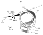
- the configuration of the capillary array 119 will be explained using FIG. 2.
- the capillary array 119 includes a plurality of capillaries 103, a capillary head 170, a detection section 101, and an electrode holding section 183. Note that the number of capillaries 103 is not limited to eight illustrated in FIG. 2 .
- the capillary 103 is a capillary tube used for sample electrophoresis, and is, for example, a glass tube with an inner diameter of several tens to several hundred ⁇ m and an outer diameter of several hundred ⁇ m, and the outer surface of which is coated with polyimide of several tens of ⁇ m for reinforcement. It is something that The capillary 103 is filled with a separation medium, which is an electrolyte solution, together with a sample.
- the separation medium may include a polymer gel, polymer, or the like.
- the plurality of capillaries 103 are held by a capillary holding part 182 having an annular shape. By holding the capillary 103 in the capillary holding section 182, the capillary array 119 can be easily carried.
- a separator 181 is provided in the capillary holding part 182 via each of a plurality of separator holding parts 185.
- the separator 181 has the same number of holes as the capillaries 103 provided at equal intervals, and each of the capillaries 103 is inserted into each hole. By inserting the capillaries 103 into the holes of the separator 181, the distances between the capillaries 103 are maintained at equal intervals, and the temperature of the capillaries 103 can be easily controlled.
- the electrode holding part 183 holds the cathode 152, which is a hollow metal electrode.
- the number of cathodes 152 and capillaries 103 are the same, one end of each of the capillaries 103 is passed through each of the cathodes 152, and both are fixed with adhesive or the like.
- the capillary head 170 is a resin member that binds the other ends of the plurality of capillaries 103 together.
- the detection unit 101 is a location where excitation lights 172 and 173 from a light source 165 are irradiated, and fluorescence is measured by a fluorescence measurement unit 167.
- the polyimide on the outer surface of the capillary 103 is removed so that excitation light irradiation and fluorescence measurement are not hindered.
- a plurality of capillaries 103 are arranged in a plane.
- the constant temperature bath 168 is a temperature regulator that maintains the capillary array 119 at a predetermined temperature, for example, 60°C.
- the voltage source 169 is a power source that applies voltage to both ends of the capillary array 119, and has an anode connected to the capillary head 170 side and a cathode connected to the electrode holding part 183 side.
- the anode side buffer solution container 160 and the cathode side buffer solution container 155 are containers in which buffer solutions 159 and 154 that supply charges during electrophoresis are stored.
- a side buffer solution container 155 is arranged on the side of the electrode holding part 183.
- the gel block 157 has a tube inside thereof to which the capillary head 170 is connected.
- the upper end of the tube of the gel block 157 is connected to a syringe 161, and the lower end of the tube is immersed in the buffer solution 159 in the anode side buffer solution container 160.
- a separation medium is injected into the capillary 103 by operating a valve 156 and a syringe 161 provided in the middle of the tube.
- FIG. 3 shows a perspective view in which the members constituting the detection unit 101 are assembled
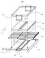
- FIG. 4 shows a perspective view in which each member is separated
- FIG. 5 shows a cross-sectional view of the detection section 101, showing an excitation light irradiation section and a detection section mounting section.
- the detection unit 101 includes a plurality of capillaries 103, a substrate 102, a fixing plate 104, and a light transmitting plate 106.
- a plurality of capillaries 103 are arranged on a substrate 102, and a fixing plate 104 and a light transmitting plate 106 are sequentially placed on the plurality of capillaries 103.
- the substrate 102 and the fixing plate 104 are made of a member that blocks light, and by bonding them together with an adhesive 105, the plurality of capillaries 103 are fixed on the substrate 102.
- the light transmitting plate 106 is made of a member that transmits light.
- the substrate 102 has a capillary array surface 111 that serves as a reference plane, and a plurality of capillaries 103 are arranged so as to be in contact with the capillary array surface 111.
- the fixing plate 104 may have V-shaped positioning grooves 118 formed at equal intervals. By fitting the capillaries 103 into the positioning grooves 118, the capillaries 103 are arranged at desired intervals. Note that when the capillaries 103 are arranged in close contact with each other on the substrate 102, that is, when the diameter of the capillaries 103 and the arrangement interval of the capillaries 103 are the same, the positioning groove 118 does not need to be formed in the fixed plate 104.
- the covering of the capillary 103 is removed and the quartz tube 115 is exposed.
- the fixing plate 104 is provided with a fluorescence passage port 112 through which fluorescence 132 from the sample passes. After passing through the fluorescence passage port 112, the fluorescence 132 passes through the light transmitting plate 106 and reaches the fluorescence measuring section 167.
- a light transmitting member 107 provided in the light transmitting plate 106 is fitted into a recess 109 provided in the substrate 102, and an adhesive or the like is applied to the shaded area shown in FIG. 102.
- the light transmitting member 107 is a member through which the excitation lights 172 and 173 irradiated onto the quartz tube 115 are transmitted.
- a sealed structure is formed in which the periphery of the quartz tube 115 of the excitation light irradiation section 164 is filled with air.
- the adhesive applied to the shaded area shown in FIG. 4 emits fluorescence, which becomes a noise signal, when the scattered light of the excitation lights 172 and 173 that passes through the light transmitting member 107 enters the adhesive. Therefore, by using a non-light transmitting member that does not transmit light as a constituent material of the substrate 102, it is possible to suppress the fluorescence emitted by the adhesive from reaching the excitation light irradiation section 164. Furthermore, by providing the convex light shielding section 113 having a convex shape on the substrate 102, it is possible to further suppress the fluorescence emitted by the adhesive from reaching the excitation light irradiation section 164.
- a detection unit installation surface 114 having a step of height S with respect to the capillary arrangement surface 111 may be provided at the four corners of the substrate 102.
- the detection unit installation surface 114 is a surface that comes into contact with the device mating surface 133 of the detection unit fixing mechanism 134 shown in FIG. Note that the detection unit fixing mechanism 134 is provided in the electrophoresis device, and a substrate presser 136 is used when bringing the detection unit installation surface 114 into contact with the device mating surface 133.
- the diameter of the quartz tube 115, the arrangement interval of the capillaries 103, and the amount of polymer filled inside the capillaries are determined. Since the laser irradiation efficiency to each capillary 103 is determined by the refractive index, by using capillary arrays 119 with different height S values depending on the analysis purpose, it is possible to use multiple analysis applications with one capillary array electrophoresis device. The sample can then be analyzed.
- the substrate 102 may be provided with an adhesive groove 108.
- the adhesive used to fix the capillary 103 to the substrate 102 may flow into the excitation light irradiation section 164 due to capillary action, and the adhesive that has flowed into the excitation light irradiation section 164 emits fluorescence that becomes a noise signal. Therefore, an adhesive groove 108 is provided in the substrate 102, which is a groove that prevents the adhesive from flowing into the excitation light irradiation section 164.
- the adhesive groove 108 is provided, for example, so as to extend in the direction in which the capillaries 103 are arranged.
- FIG. 6 is a cross-sectional view of the detection unit 101, and the light transmission plate 106 is omitted.
- the adhesive groove 108 is provided between a location where an adhesive used for fixing the capillary 103 is applied and the excitation light irradiation section 164. Although a part of the adhesive used to fix the capillary 103 becomes surplus adhesive 116 and tries to flow into the excitation light irradiation section 164, it accumulates in the adhesive groove 108, so the surplus adhesive 116 is on the surface near the excitation light. Does not reach 110.
- the adhesive groove 108 does not need to be formed from end to end of the substrate 102, and may be provided at a location where the adhesive is applied.
- the adhesive groove 108 is covered by the area of the fixing plate 104 where the fluorescence passage hole 112 is not formed, the adhesive fluorescence 117 emitted from the excess adhesive 116 accumulated in the adhesive groove 108 reaches the fluorescence measuring section 167. do not. That is, by providing the fixing plate 104, which serves as a light shielding portion, between the adhesive groove 108 and the fluorescence measuring section 167, the adhesive fluorescence 117, which serves as a noise signal, is shielded.
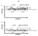
- FIG. 7(a) is an example of a measurement signal when the noise signal cannot be sufficiently reduced
- FIG. 7(b) is an example of a measurement signal by the detection unit 101 of the first embodiment.
- the vertical axis in FIG. 7 is the signal intensity measured by the fluorescence measuring section 167
- the horizontal axis is the electrophoresis time
- the signal intensity is displayed enlarged in the vertical axis direction.
- the baseline intensity rises to H as illustrated in FIG.
- the signal intensity I S of the fluorescence S is buried in the amplitude I N of the noise N and cannot be detected.
- the baseline intensity decreases to L and the signal intensity of the noise N′ changes as illustrated in FIG.
- the width I N ' becomes small, and the signal intensity I S ' of the fluorescence S' from the sample can be detected without being buried in the amplitude I N of the noise N'. Note that the fluorescence S from the sample does not depend on the baseline intensity, and the signal intensity I S and the signal intensity I S ' are the same.
- noise signals caused by foreign objects around the excitation light irradiation section 164 can be reduced.
- the sensitivity limit is reduced, and even when the fluorescence from the sample is small, it can be detected.
- Example 1 the case where the excitation light vicinity surface 110 of the substrate 102 is approximately the same height as the capillary array surface 111, and the detection unit installation surface 114 has a step of height S with respect to the capillary array surface 111 was described. .
- Example 2 a case will be described in which the excitation light vicinity surface 210 of the substrate 202 is formed at a position lower than the capillary array surface 211 by a height T, and the detection unit installation surface 214 is at the same height as the capillary array surface 211. .
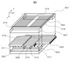
- FIG. 8 is a perspective view showing a state in which a substrate 202, a plurality of capillaries 203, and a fixing plate 204 constituting the detection unit 201 are assembled, and a light transmitting plate 206 is separated.
- the substrate 202 has a capillary arrangement surface 211, a detection unit installation surface 214, an adhesive groove 208, a recessed portion 209, and a convex light shielding portion 213, as in the first embodiment.
- the fixing plate 204 includes a fluorescence passage hole 212 and is bonded to the substrate 202 with an adhesive 205, as in the first embodiment.
- the light transmitting plate 206 includes a light transmitting member 207 as in the first embodiment.
- the detection unit installation surface 214 is at the same height as the capillary arrangement surface 211, and there is no need to process a step of height S as shown in Example 1. The production becomes easier.
- the excitation lights 172 and 173 irradiated onto the quartz tube 215 with respect to the excitation light vicinity surface 210, one excitation light follows the path of the other excitation light and returns to the light source 165. It may be possible to prevent this. Although the excitation lights 172 and 173 tilted with respect to the excitation light vicinity surface 210 may be blocked by the substrate 202, the excitation light vicinity surface 210 is formed at a position lower than the capillary arrangement surface 211 by a height T. As a result, the excitation lights 172 and 173 are not blocked by the substrate 202.
- the convex light shielding portion 113 is provided so that the excitation light 172 and 173 are not blocked by the substrate 102.
- a slope may be provided at the end.
- the periphery of the quartz tube 215 of the excitation light irradiation section 164 has a sealed structure filled with air, so as in the first embodiment, noise signals caused by foreign objects around the excitation light irradiation section 164 can be reduced. Sensitivity limit is reduced.
- Example 1 it has been explained that a plurality of capillaries 103 are fixed by the fixing plate 104 that is adhered to the substrate 102.
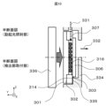
- Example 3 a case will be described in which a plurality of capillaries 303 are fixed by a light transmitting plate 306.
- FIG. 9 is a perspective view showing a state in which a substrate 302 and a plurality of capillaries 303 constituting a detection unit 301 are assembled and a light transmitting plate 306 is separated. Further, FIG. 10 shows an excitation light irradiation section and a detection section mounting section as a cross-sectional view of the detection section 301. Note that the substrate 302 has a capillary array surface 311, an adhesive groove 308, and a convex light shielding portion 313, as in the first embodiment.
- a plurality of capillaries 303 arranged on the capillary arrangement surface 311 of the substrate 302 illustrated in FIG. 9 are adhesively fixed by a light transmitting plate 306.
- a light shielding material 316 is coated on the lower surface of the light transmitting plate 306, that is, the surface in contact with the plurality of capillaries 303, by vapor deposition or the like. However, the region of the fluorescence passage hole 312 is not coated with the light shielding material 316.
- a positioning guide 317 is provided on the capillary arrangement surface 311 of the substrate 302.
- the positioning guide 317 is formed, for example, by using a dispenser to apply an adhesive at equal intervals and then curing it.
- the capillaries 303 are arranged at equal intervals. Therefore, by changing the interval between adhesives applied to the capillary array surface 311, the array interval of the capillaries 303 can be changed.
- the light transmitting member 307 is provided with a detection unit installation surface 314.
- the detection unit installation surface 314 contacts the device mating surface 335 of the detection unit fixing mechanism 334, as illustrated in FIG.
- the detection unit fixing mechanism 334 is provided in the electrophoresis device, and a substrate presser 136 is used when bringing the detection unit installation surface 314 into contact with the device mating surface 335.
- the area around the quartz tube 315 of the excitation light irradiation section 164 has a sealed structure filled with air, so as in the first embodiment, noise signals caused by foreign objects around the excitation light irradiation section 164 can be reduced. , the sensitivity limit becomes smaller.
- the detection unit 101 includes the light transmitting plate 106 and the light transmitting member 307 .
- the light transmitting plate 106 and the light transmitting member 307 which are relatively expensive members, are mounted on the capillary array 119, which is a consumable item, the unit price of the capillary array 119 increases, and the running cost also increases. Therefore, in the fourth embodiment, running costs are suppressed by installing substitutes for the light transmitting plate 306 and the light transmitting member 307 in the electrophoresis apparatus.
- FIG. 11 is a perspective view showing a state in which a substrate 402, a plurality of capillaries 403, and a fixing plate 404 constituting a detection unit 401 of Example 4 are assembled.
- FIG. 12 shows a perspective view of the main part of the electrophoresis device to which the detection section 401 is attached.
- the substrate 402 has a capillary array surface 411, a detection unit installation surface 414, an adhesive groove 408, and a recess 409, as in the first embodiment.
- the fixing plate 404 includes a fluorescence passage hole 412 and a positioning groove 418, and is bonded to the substrate 402 with an adhesive 405.
- the electrophoresis apparatus illustrated in FIG. 12 includes a light source 465 and a fluorescence measuring section 467, as in the first embodiment.
- Excitation light 431 emitted from a light source 465 is split into two excitation lights by a half mirror 471, passes through a plurality of mirrors 474 and a condensing lens 475, and then passes through excitation light exit holes 476 (two locations, upper and lower).
- the excitation light exit hole 476 is provided in the detection unit fixing mechanism 434 to which the detection unit 401 is attached, and the excitation light exit hole 476 includes an excitation light transmission window 477.
- the excitation light transmission window 477 fits into the recess 409 of the detection unit 401, and the excitation light transmitted through the excitation light transmission window 477 is irradiated onto the excitation light irradiation unit 464. Ru. That is, the excitation light transmission window 477 becomes a substitute for the light transmission member 307.
- Fluorescence 432 emitted from the excitation light irradiation unit 464 by irradiation with excitation light is measured by the fluorescence measurement unit 467 after passing through a fluorescence transmission window 478 provided in the fluorescence entrance hole 479. That is, the fluorescent light transmitting window 478 becomes a substitute for the light transmitting plate 306.
- the fluorescence measuring section 467 includes a fluorescence condensing lens 481, a transmission type diffraction grating 482, an imaging lens 483, and a two-dimensional CCD 484.
- the light transmitting plate 106 and the light transmitting member 307 which are relatively expensive members, do not need to be mounted on the capillary array 119, which is a consumable item, so running costs can be suppressed.
- the area around the quartz tube 415 of the excitation light irradiation section 164 has a sealed structure filled with air, so as in the first embodiment, noise signals caused by foreign objects around the excitation light irradiation section 164 can be reduced. , the sensitivity limit becomes smaller.
- Electrode holding part 185... Separator holding part, 316... Light shielding material, 320... Light transmitting member mating surface, 476... Excitation light exit hole, 477... Excitation light transmission window, 478... Fluorescence transmission window, 479... Fluorescence Entrance hole, 481... Fluorescence condensing lens, 482... Transmission type diffraction grating, 483... Imaging lens, 484... Two-dimensional CCD.
Landscapes
- Health & Medical Sciences (AREA)
- Life Sciences & Earth Sciences (AREA)
- Molecular Biology (AREA)
- Chemical & Material Sciences (AREA)
- Analytical Chemistry (AREA)
- Physics & Mathematics (AREA)
- Biochemistry (AREA)
- General Health & Medical Sciences (AREA)
- General Physics & Mathematics (AREA)
- Immunology (AREA)
- Pathology (AREA)
- Chemical Kinetics & Catalysis (AREA)
- Electrochemistry (AREA)
- Nuclear Medicine, Radiotherapy & Molecular Imaging (AREA)
- Biomedical Technology (AREA)
- Engineering & Computer Science (AREA)
- Investigating, Analyzing Materials By Fluorescence Or Luminescence (AREA)
Abstract
Description
Claims (6)
- 試料の電気泳動に用いられるキャピラリが平面状に配列されるキャピラリアレイと、
前記キャピラリアレイに励起光を照射する励起光源と、
前記キャピラリアレイから誘起される蛍光を測定する蛍光測定部を備える電気泳動装置であって、
前記キャピラリアレイは、前記励起光が照射される箇所である励起光照射部の周辺が空気で満たされる密閉構造を有することを特徴とする電気泳動装置。 - 請求項1に記載の電気泳動装置であって、
前記キャピラリアレイが配列され、接着剤によって固定される基板には、前記接着剤が塗布される箇所である塗布部と前記励起光照射部との間に溝が設けられることを特徴とする
ことを特徴とする電気泳動装置。 - 請求項2に記載の電気泳動装置であって、
前記溝と前記蛍光測定部との間には、光を遮る遮光部が設けられることを特徴とする電気泳動装置。 - 請求項2に記載の電気泳動装置であって、
前記基板は光を透過させない非光透過部材で構成されることを特徴とする電気泳動装置。 - 試料の電気泳動に用いられるキャピラリが平面状に配列されるキャピラリアレイと、
前記キャピラリアレイに励起光を照射する励起光源と、
前記キャピラリアレイから誘起される蛍光を測定する蛍光測定部を備える電気泳動装置であって、
前記キャピラリアレイが配列され、接着剤によって固定される基板には、前記接着剤が塗布される箇所である塗布部と前記励起光が照射される箇所である励起光照射部との間に溝が設けられることを特徴とする電気泳動装置。 - 試料の電気泳動に用いられるキャピラリが平面状に配列されるキャピラリアレイであって、
励起光が照射される箇所である励起光照射部の周辺が空気で満たされる密閉構造を有することを特徴とするキャピラリアレイ。
Priority Applications (6)
| Application Number | Priority Date | Filing Date | Title |
|---|---|---|---|
| GB2500123.1A GB2635618A (en) | 2022-08-29 | 2022-08-29 | Electrophoresis device and capillary array |
| JP2024543614A JPWO2024047701A1 (ja) | 2022-08-29 | 2022-08-29 | |
| CN202280097445.9A CN119422056A (zh) | 2022-08-29 | 2022-08-29 | 电泳装置和毛细管阵列 |
| US18/876,238 US20250369887A1 (en) | 2022-08-29 | 2022-08-29 | Electrophoresis device and capillary array |
| DE112022007091.9T DE112022007091T5 (de) | 2022-08-29 | 2022-08-29 | Elektrophoresevorrichtung und kapillarfeld |
| PCT/JP2022/032425 WO2024047701A1 (ja) | 2022-08-29 | 2022-08-29 | 電気泳動装置とキャピラリアレイ |
Applications Claiming Priority (1)
| Application Number | Priority Date | Filing Date | Title |
|---|---|---|---|
| PCT/JP2022/032425 WO2024047701A1 (ja) | 2022-08-29 | 2022-08-29 | 電気泳動装置とキャピラリアレイ |
Publications (1)
| Publication Number | Publication Date |
|---|---|
| WO2024047701A1 true WO2024047701A1 (ja) | 2024-03-07 |
Family
ID=90099098
Family Applications (1)
| Application Number | Title | Priority Date | Filing Date |
|---|---|---|---|
| PCT/JP2022/032425 Ceased WO2024047701A1 (ja) | 2022-08-29 | 2022-08-29 | 電気泳動装置とキャピラリアレイ |
Country Status (6)
| Country | Link |
|---|---|
| US (1) | US20250369887A1 (ja) |
| JP (1) | JPWO2024047701A1 (ja) |
| CN (1) | CN119422056A (ja) |
| DE (1) | DE112022007091T5 (ja) |
| GB (1) | GB2635618A (ja) |
| WO (1) | WO2024047701A1 (ja) |
Citations (3)
| Publication number | Priority date | Publication date | Assignee | Title |
|---|---|---|---|---|
| JP2007322218A (ja) * | 2006-05-31 | 2007-12-13 | Hitachi High-Technologies Corp | 電気泳動装置 |
| JP2010096778A (ja) * | 2001-09-28 | 2010-04-30 | Hitachi Ltd | 電気泳動装置 |
| JP2011209301A (ja) * | 2004-07-19 | 2011-10-20 | Cell Biosciences Inc | 分析対象物の検出のための方法およびデバイス |
-
2022
- 2022-08-29 JP JP2024543614A patent/JPWO2024047701A1/ja active Pending
- 2022-08-29 WO PCT/JP2022/032425 patent/WO2024047701A1/ja not_active Ceased
- 2022-08-29 GB GB2500123.1A patent/GB2635618A/en active Pending
- 2022-08-29 US US18/876,238 patent/US20250369887A1/en active Pending
- 2022-08-29 CN CN202280097445.9A patent/CN119422056A/zh active Pending
- 2022-08-29 DE DE112022007091.9T patent/DE112022007091T5/de active Pending
Patent Citations (3)
| Publication number | Priority date | Publication date | Assignee | Title |
|---|---|---|---|---|
| JP2010096778A (ja) * | 2001-09-28 | 2010-04-30 | Hitachi Ltd | 電気泳動装置 |
| JP2011209301A (ja) * | 2004-07-19 | 2011-10-20 | Cell Biosciences Inc | 分析対象物の検出のための方法およびデバイス |
| JP2007322218A (ja) * | 2006-05-31 | 2007-12-13 | Hitachi High-Technologies Corp | 電気泳動装置 |
Also Published As
| Publication number | Publication date |
|---|---|
| CN119422056A (zh) | 2025-02-11 |
| US20250369887A1 (en) | 2025-12-04 |
| JPWO2024047701A1 (ja) | 2024-03-07 |
| GB2635618A (en) | 2025-05-21 |
| GB202500123D0 (en) | 2025-02-19 |
| DE112022007091T5 (de) | 2025-03-20 |
Similar Documents
| Publication | Publication Date | Title |
|---|---|---|
| JP3429282B2 (ja) | 自動化されたシステム、及びサンプルの分析方法 | |
| US9285321B2 (en) | Fluorescence detection device | |
| US7136161B2 (en) | Component analyzing apparatus with microchip | |
| CN117491459A (zh) | 用于样品分离的光学系统和方法 | |
| KR101712691B1 (ko) | 볼엔드 입출력 광섬유를 이용한 생체분석 장치 및 방법 | |
| US5594545A (en) | Microflow cell | |
| JP2776208B2 (ja) | 電気泳動装置 | |
| JP2002296235A (ja) | キャピラリアレイ及びキャピラリアレイ光検出装置 | |
| JP2002214194A (ja) | 電気泳動装置 | |
| WO2024047701A1 (ja) | 電気泳動装置とキャピラリアレイ | |
| US10359394B2 (en) | Capillary electrophoresis device and capillary cassette using the same | |
| JP4398399B2 (ja) | キャピラリ電気泳動装置、及びキャピラリ電気泳動方法 | |
| JP3701283B2 (ja) | 電気泳動システムのためのエネルギービームガイド | |
| US10775307B2 (en) | Optical fiber fluorescence detection device | |
| JP2008197053A (ja) | 生体試料用の流路形成チップ及び生体試料用の流路形成チップの製造方法 | |
| JP2005070031A (ja) | マイクロチップを用いた成分分析装置 | |
| US20240102916A1 (en) | Emission optical system, emission device, and optical measurement device | |
| US10935497B2 (en) | Detection device for luminescence analysis and automated analyzer | |
| JP4474257B2 (ja) | 電気泳動装置 | |
| JP4029896B2 (ja) | キャピラリアレイ | |
| JP4577322B2 (ja) | キャピラリアレイとキャップのセット | |
| CN120283162A (zh) | 毛细管电泳装置 |
Legal Events
| Date | Code | Title | Description |
|---|---|---|---|
| 121 | Ep: the epo has been informed by wipo that ep was designated in this application |
Ref document number: 22957305 Country of ref document: EP Kind code of ref document: A1 |
|
| WWE | Wipo information: entry into national phase |
Ref document number: 2024543614 Country of ref document: JP |
|
| WWE | Wipo information: entry into national phase |
Ref document number: 112022007091 Country of ref document: DE Ref document number: 18876238 Country of ref document: US |
|
| WWE | Wipo information: entry into national phase |
Ref document number: 202280097445.9 Country of ref document: CN |
|
| ENP | Entry into the national phase |
Ref document number: 202500123 Country of ref document: GB Kind code of ref document: A Free format text: PCT FILING DATE = 20220829 |
|
| WWE | Wipo information: entry into national phase |
Ref document number: 2500123.1 Country of ref document: GB |
|
| WWP | Wipo information: published in national office |
Ref document number: 202280097445.9 Country of ref document: CN |
|
| WWP | Wipo information: published in national office |
Ref document number: 112022007091 Country of ref document: DE |
|
| WWE | Wipo information: entry into national phase |
Ref document number: 11202500121W Country of ref document: SG |
|
| WWP | Wipo information: published in national office |
Ref document number: 11202500121W Country of ref document: SG |
|
| WWP | Wipo information: published in national office |
Ref document number: 2500123.1 Country of ref document: GB |
|
| 122 | Ep: pct application non-entry in european phase |
Ref document number: 22957305 Country of ref document: EP Kind code of ref document: A1 |
|
| WWP | Wipo information: published in national office |
Ref document number: 18876238 Country of ref document: US |