WO2024043034A1 - X-ray inspecting device and x-ray inspecting method - Google Patents
X-ray inspecting device and x-ray inspecting method Download PDFInfo
- Publication number
- WO2024043034A1 WO2024043034A1 PCT/JP2023/028447 JP2023028447W WO2024043034A1 WO 2024043034 A1 WO2024043034 A1 WO 2024043034A1 JP 2023028447 W JP2023028447 W JP 2023028447W WO 2024043034 A1 WO2024043034 A1 WO 2024043034A1
- Authority
- WO
- WIPO (PCT)
- Prior art keywords
- ray
- scintillator
- rays
- area
- visible light
- Prior art date
Links
- 238000000034 method Methods 0.000 title claims description 26
- 238000003384 imaging method Methods 0.000 claims abstract description 75
- 238000005259 measurement Methods 0.000 claims abstract description 63
- 230000005855 radiation Effects 0.000 claims abstract description 21
- 238000007689 inspection Methods 0.000 claims description 85
- 238000010191 image analysis Methods 0.000 claims description 10
- 230000002159 abnormal effect Effects 0.000 claims description 4
- 230000007547 defect Effects 0.000 description 41
- 238000010586 diagram Methods 0.000 description 18
- 101100479031 Caenorhabditis elegans aars-2 gene Proteins 0.000 description 13
- 230000032258 transport Effects 0.000 description 13
- 101100479039 Caenorhabditis elegans aars-1 gene Proteins 0.000 description 11
- 230000000694 effects Effects 0.000 description 9
- 230000005540 biological transmission Effects 0.000 description 5
- XEEYBQQBJWHFJM-UHFFFAOYSA-N Iron Chemical compound [Fe] XEEYBQQBJWHFJM-UHFFFAOYSA-N 0.000 description 2
- 238000010521 absorption reaction Methods 0.000 description 2
- 238000005401 electroluminescence Methods 0.000 description 2
- 239000000835 fiber Substances 0.000 description 2
- 229910052751 metal Inorganic materials 0.000 description 2
- 239000002184 metal Substances 0.000 description 2
- 230000004048 modification Effects 0.000 description 2
- 238000012986 modification Methods 0.000 description 2
- 239000007787 solid Substances 0.000 description 2
- 229910052782 aluminium Inorganic materials 0.000 description 1
- XAGFODPZIPBFFR-UHFFFAOYSA-N aluminium Chemical compound [Al] XAGFODPZIPBFFR-UHFFFAOYSA-N 0.000 description 1
- 230000000295 complement effect Effects 0.000 description 1
- 239000013078 crystal Substances 0.000 description 1
- 238000001514 detection method Methods 0.000 description 1
- 238000005516 engineering process Methods 0.000 description 1
- 238000009434 installation Methods 0.000 description 1
- 230000010354 integration Effects 0.000 description 1
- 229910052742 iron Inorganic materials 0.000 description 1
- 239000004973 liquid crystal related substance Substances 0.000 description 1
- 229910044991 metal oxide Inorganic materials 0.000 description 1
- 150000004706 metal oxides Chemical class 0.000 description 1
- 239000002245 particle Substances 0.000 description 1
- 239000011347 resin Substances 0.000 description 1
- 229920005989 resin Polymers 0.000 description 1
- 239000004065 semiconductor Substances 0.000 description 1
- 230000035945 sensitivity Effects 0.000 description 1
- 238000004846 x-ray emission Methods 0.000 description 1
Images


Classifications
-
- G—PHYSICS
- G01—MEASURING; TESTING
- G01N—INVESTIGATING OR ANALYSING MATERIALS BY DETERMINING THEIR CHEMICAL OR PHYSICAL PROPERTIES
- G01N23/00—Investigating or analysing materials by the use of wave or particle radiation, e.g. X-rays or neutrons, not covered by groups G01N3/00 – G01N17/00, G01N21/00 or G01N22/00
- G01N23/02—Investigating or analysing materials by the use of wave or particle radiation, e.g. X-rays or neutrons, not covered by groups G01N3/00 – G01N17/00, G01N21/00 or G01N22/00 by transmitting the radiation through the material
- G01N23/04—Investigating or analysing materials by the use of wave or particle radiation, e.g. X-rays or neutrons, not covered by groups G01N3/00 – G01N17/00, G01N21/00 or G01N22/00 by transmitting the radiation through the material and forming images of the material
-
- G—PHYSICS
- G01—MEASURING; TESTING
- G01N—INVESTIGATING OR ANALYSING MATERIALS BY DETERMINING THEIR CHEMICAL OR PHYSICAL PROPERTIES
- G01N23/00—Investigating or analysing materials by the use of wave or particle radiation, e.g. X-rays or neutrons, not covered by groups G01N3/00 – G01N17/00, G01N21/00 or G01N22/00
- G01N23/02—Investigating or analysing materials by the use of wave or particle radiation, e.g. X-rays or neutrons, not covered by groups G01N3/00 – G01N17/00, G01N21/00 or G01N22/00 by transmitting the radiation through the material
- G01N23/06—Investigating or analysing materials by the use of wave or particle radiation, e.g. X-rays or neutrons, not covered by groups G01N3/00 – G01N17/00, G01N21/00 or G01N22/00 by transmitting the radiation through the material and measuring the absorption
- G01N23/18—Investigating the presence of flaws defects or foreign matter
-
- G—PHYSICS
- G01—MEASURING; TESTING
- G01T—MEASUREMENT OF NUCLEAR OR X-RADIATION
- G01T1/00—Measuring X-radiation, gamma radiation, corpuscular radiation, or cosmic radiation
- G01T1/16—Measuring radiation intensity
- G01T1/20—Measuring radiation intensity with scintillation detectors
-
- G—PHYSICS
- G21—NUCLEAR PHYSICS; NUCLEAR ENGINEERING
- G21K—TECHNIQUES FOR HANDLING PARTICLES OR IONISING RADIATION NOT OTHERWISE PROVIDED FOR; IRRADIATION DEVICES; GAMMA RAY OR X-RAY MICROSCOPES
- G21K5/00—Irradiation devices
- G21K5/02—Irradiation devices having no beam-forming means
Definitions
- the present invention relates to an X-ray inspection device and an X-ray inspection method.
- X-rays are emitted to a measurement target, the X-rays that pass through the measurement target are converted into visible light by a scintillator (the X-rays emit fluorescence and the visible light is emitted), and the visible light is sent to an imaging device.
- An X-ray inspection apparatus that generates an X-ray image by capturing images is known (for example, see Patent Documents 1 and 2).
- the X-ray inspection apparatus described in Patent Document 1 is a so-called transmission imaging type X-ray inspection apparatus. Specifically, the transmission imaging type X-ray inspection apparatus generates an X-ray image by capturing visible light emitted from a surface of the scintillator that is opposite to the incident surface on which X-rays enter.
- the X-ray inspection apparatus described in Patent Document 2 is a so-called reflection imaging type X-ray inspection apparatus. Specifically, the reflection imaging type X-ray inspection apparatus generates an X-ray image by capturing visible light emitted from an incident surface on which X-rays enter a scintillator.
- the transmission imaging type X-ray inspection apparatus described in Patent Document 1 when X-rays are incident on the scintillator, visible light converted by the scintillator travels inside the scintillator. It is absorbed by. For this reason, the brightness of the visible light emitted from the surfaces that are opposite to the entrance surface becomes low, resulting in a dark X-ray image. Furthermore, when a particle-type scintillator is employed, visible light traveling inside the scintillator is likely to be scattered within the scintillator. For this reason, the X-ray image becomes an unclear image. That is, the transmission imaging type X-ray inspection apparatus described in Patent Document 1 has a problem in that the X-ray image becomes a dark image or an unclear image, making it difficult to obtain an X-ray image suitable for inspection. .
- the reflection imaging type X-ray inspection device described in Patent Document 2 In addition, in the reflection imaging type X-ray inspection device described in Patent Document 2, visible light emitted from the incident surface of the scintillator where X-rays enter must travel toward the imaging device, so the scintillator is measured. It needs to be tilted towards the target. Therefore, the distance between the measurement target and the scintillator becomes relatively large. As a result, the blur (penumbra) that occurs in the X-ray image becomes large, and the X-ray image becomes an unclear image. That is, the reflection imaging type X-ray inspection apparatus described in Patent Document 2 has a problem in that the X-ray image becomes an unclear image and it is difficult to obtain an X-ray image suitable for inspection. Therefore, there is a need for a technology that can obtain X-ray images suitable for examination.
- the present invention has been made in view of the above, and an object of the present invention is to provide an X-ray inspection apparatus and an X-ray inspection method that can obtain an X-ray image suitable for inspection.
- an X-ray inspection apparatus includes an X-ray emitting device that emits X-rays toward a measurement object, and an The scintillator includes a scintillator that converts radiation into visible light, and an imaging device that images the visible light from the scintillator to generate an X-ray image, and the scintillator has an incident surface on which the X-rays enter and an incident surface on which the X-rays enter.
- the imaging device is arranged such that the boundary with the intersecting first side surface is located within the radiation range of the X-ray, and the imaging device covers the entire area of the first side surface with the first area including the boundary; When partitioned into two regions, a second region excluding the first region, the first region is arranged so as to face the first side surface, and the first region out of the entire region of the first side surface is The visible light emitted from the region is imaged.
- the entire area of the entrance surface is divided into two areas: a third area including the boundary and a fourth area excluding the third area. further comprising an X-ray shielding member that is disposed between the measurement target and the scintillator and that shields the X-rays that enter the fourth region of the entire region of the incident surface. .
- the scintillator has a dimension between the first side surface and a second side surface that is opposite to the first side surface and is 30 ⁇ m or more and 500 ⁇ m or less. is set to .
- the X-ray inspection apparatus further includes an image analysis device that analyzes the X-ray image, and the image analysis device includes a Based on the luminance distribution of visible light, a feature quantity of an abnormal location existing in the measurement object is estimated.
- the X-ray emitting device and the scintillator set a distance L1 [mm] from the X-ray focal point of the X-ray emitting device to the measurement object, and the X-ray
- L1 [mm] the distance from the line focus to the scintillator
- R [ ⁇ m] the diameter of the X-ray focus
- the width of the penumbra represented by (L2-L1) x R/L1 is 30 ⁇ m or less It is set up so that.
- the measurement target is placed in a direction substantially perpendicular to the first side surface relative to the X-ray emitting device, the scintillator, and the imaging device. It further includes a conveying device that moves or repeats the relative movement and stopping.
- the scintillator is arranged such that a boundary between an incident surface on which X-rays enter the scintillator and a first side surface that intersects the incident surface is located within the radiation range of the X-rays.
- an imaging device arranging step of arranging an imaging device to face the first side surface; an X-ray radiation step of radiating the X-rays from the X-ray device toward the measurement target; an imaging step in which the X-rays that have passed through the measurement object are incident on the scintillator, and the visible light converted by the scintillator is imaged by the imaging device to generate an X-ray image, and in the imaging step,
- the imaging device arranging step of arranging an imaging device to face the first side surface
- an X-ray radiation step of radiating the X-rays from the X-ray device toward the measurement target
- an imaging step in which the X-rays that have passed through the measurement object are incident on the scintillator, and the visible light converted by the scintillator is imaged by the imaging device to generate an X-ray image, and in the imaging step,
- the entire area of the first side surface is divided into two areas, a first area including the boundary and a second area excluding the first
- the entire area of the entrance surface is divided into two areas: a third area including the boundary and a fourth area excluding the third area.
- an X-ray shielding member for disposing an X-ray shielding member for shielding the X-rays between the measurement object and the scintillator in order to shield the X-rays incident on the fourth region when the fourth region is divided into
- the method further includes a placement step.
- the X-ray inspection method further includes an image analysis step of analyzing the X-ray image, and in the image analysis step, the Based on the luminance distribution of visible light, a feature quantity of an abnormal location existing in the measurement object is estimated.
- the X-ray inspection method further includes a positional relationship adjustment step of adjusting the positional relationship between the X-ray emitting device and the scintillator, and in the positional relationship adjusting step, the X-ray radiation
- a positional relationship adjustment step of adjusting the positional relationship between the X-ray emitting device and the scintillator, and in the positional relationship adjusting step, the X-ray radiation
- the distance from the X-ray focus of the device to the measurement target is L1 [mm]
- the distance from the X-ray focus to the scintillator is L2 [mm]
- the diameter of the X-ray focus is R [ ⁇ m].
- (L2-L1) ⁇ R/L1 The position of the X-ray emitting device and the scintillator is such that the width of the penumbra is 1/6 or less of the diameter of the defect to be detected for the measurement object. Adjust relationships.
- the measurement target is placed in a direction substantially perpendicular to the first side surface relative to the X-ray emitting device, the scintillator, and the imaging device. It further includes a conveying step of moving or repeating the relative movement and stopping.
- the X-ray inspection device and the X-ray inspection method according to the present invention it is possible to obtain an X-ray image suitable for inspection.
- FIG. 1 is a diagram showing an X-ray inspection apparatus according to the first embodiment.
- FIG. 2 is a flowchart showing the X-ray inspection method.
- FIG. 3 is a diagram illustrating step S1.
- FIG. 4 is a diagram illustrating step S5.
- FIG. 5 is a diagram showing an X-ray inspection apparatus according to the second embodiment.
- FIG. 6 is a diagram illustrating the effects of the second embodiment.
- FIG. 7 is a diagram showing an X-ray inspection apparatus according to Embodiment 3.
- FIG. 8 is a diagram illustrating the effects of the third embodiment.
- FIG. 9 is a diagram illustrating a modification of the first to third embodiments.
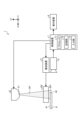
- FIG. 1 is a diagram showing an X-ray inspection apparatus 1 according to the first embodiment.
- the X-ray inspection device 1 emits X-rays to a measurement object OB (FIG. 1) such as a film or fiber, converts the X-rays transmitted through the measurement object OB into visible light, images the visible light, and generates an X-ray image. Generate a line image.
- the X-ray inspection apparatus 1 estimates the feature amount of the defect DE (see FIG. 3) such as a foreign metal object mixed in the measurement object OB by analyzing the X-ray image.
- the OB to be measured is not limited to films or fibers, but may also be paper, resin, integrated circuits, or the like.
- this X-ray inspection apparatus 1 includes an X-ray emitting device 2, a transport device 3, a scintillator 4, an imaging device 5, a display device 6, and a control device 7.
- the axis along the vertical direction will be referred to as the Z-axis
- the two axes orthogonal to the Z-axis will be referred to as the X-axis and the Y-axis.
- the Z axis is an axis along the vertical direction.
- the X-axis is an axis along the left-right direction.
- the Y-axis is an axis perpendicular to the plane of the paper in FIG.
- the X-ray emitting device 2 emits a conical X-ray beam (cone beam) from an X-ray focal point 21 (FIG. 1) toward the measurement object OB under the control of the control device 7.
- the radiation range SP of the conical X-ray beam is expressed by dots.
- the radiation direction of the X-rays from the X-ray radiation device 2 is the ⁇ Z-axis direction (downward in FIG. 1).
- the X-ray emitting device 2 may be of a closed type or an open type, and may be of a millifocus type or a microfocus type.
- the conveyance device 3 includes a conveyance roller, a belt conveyor, etc., and conveys the measurement target OB while holding the measurement target OB under the control of the control device 7.
- the transport direction of the measurement target OB is the -X axis direction (rightward in FIG. 1).
- the ⁇ X-axis direction is approximately perpendicular to the first side surface 42, which will be described later.
- the scintillator 4 is composed of a plate having a rectangular shape in plan view, and is disposed on the ⁇ Z-axis side with respect to the measurement object OB with the plate surface substantially parallel to the XY plane. Then, the scintillator 4 converts the incident X-rays after passing through the measurement object OB into visible light (fluorescence is emitted by the X-rays).
- the plate surface on the +Z-axis side (upper side in FIG. 1) is where the X-rays transmitted through the measurement object OB enter, and corresponds to the entrance surface 41 (FIG. 1) according to the present invention.
- the side surface on the -X axis side intersects the incident surface 41 and corresponds to the first side surface 42 (FIG. 1) according to the present invention.
- the scintillator 4 may be of either a particle type or a single crystal type.
- the imaging device 5 includes an imaging element such as a CCD (Charge Coupled Device) or a CMOS (Complementary Metal Oxide Semiconductor) that receives incident light and converts it into an electrical signal, and images the visible light from the scintillator 4 to generate X-rays. It is a camera that generates images. The imaging device 5 then outputs the generated X-ray image data to the control device 7. Note that the imaging device 5 may be a line sensor camera, an area sensor camera, or a time delay and integration type camera.
- CCD Charge Coupled Device
- CMOS Complementary Metal Oxide Semiconductor
- the display device 6 is configured with a display using liquid crystal or organic EL (Electro Luminescence), and displays various images such as X-ray images under the control of the control device 7.
- liquid crystal or organic EL Electro Luminescence
- the control device 7 centrally controls the operation of the entire X-ray inspection apparatus 1 .
- the control device 7 includes a processor 71, a storage section 72, and an input section 73.
- the processor 71 is realized by executing various programs stored in the storage section 72 by a controller such as a CPU (Central Processing Unit) or an MPU (Micro Processing Unit), and controls the overall operation of the X-ray inspection apparatus 1. Control.
- the processor 71 is not limited to a CPU or an MPU, and may be configured by an integrated circuit such as an ASIC (Application Specific Integrated Circuit) or an FPGA (Field-Programmable Gate Array). The functions of the processor 71 will be explained in "X-ray inspection method" described later.
- the storage unit 72 stores various programs executed by the processor 71 as well as data necessary for the processor 71 to perform processing.
- the input unit 73 includes buttons, switches, touch panels, etc. that accept user operations by a worker, and outputs operation signals to the processor 71 in accordance with the user operations. Note that part or all of the functions of the input unit 73 may be arranged on the display screen of the display device 6 as a touch panel.
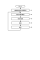
- FIG. 2 is a flowchart showing the X-ray inspection method.
- step S1 an operator performs initial settings of the X-ray inspection apparatus 1 (step S1).
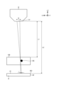
- FIG. 3 is a diagram illustrating step S1. Specifically, FIG. 3 is a diagram showing the positional relationship among the X-ray emitting device 2, the measurement object OB, and the scintillator 4.
- the symbol “R” is the diameter [ ⁇ m] of the X-ray focal point 21.
- the symbol “L1” is the distance [mm] from the X-ray focal point 21 to the measurement object OB.
- the symbol “L2” is the distance [mm] from the X-ray focal point 21 to the scintillator 4.
- the symbol “r” is the width [ ⁇ m] of the penumbra (blur) SH.
- penumbra SH in X-ray examination will be explained.
- the distance (L2-L1) from the measurement target OB to the scintillator 4 is increased, and the shadow of defects DE such as metal foreign objects mixed in the measurement target OB due to the emitted X-rays is geometrically If it is made larger than that, the detection sensitivity for minute defects DE will become low.
- the X-ray focal point 21 has a finite diameter R [ ⁇ m]. For this reason, X-rays enter the region that should originally be the shadow of the defect DE, resulting in a penumbra SH (FIG. 3). That is, since the penumbra SH occurs in a portion that would normally be a shadow of the defect DE, it becomes difficult to detect the defect DE with high accuracy.
- the penumbra SH occurs at both ends of the defect DE. Therefore, the shadow of the defect DE becomes smaller by 2 ⁇ r than originally.
- the width r of the penumbra SH is expressed as (L2-L1) ⁇ R/L1.
- the inventor of the present application found that in order to stably detect the defect DE, it is necessary to make the width r of the penumbra SH 1/6 or less of the diameter of the defect DE. I found it.
- the diameter of the defect DE is 30 ⁇ m or more and 200 ⁇ m or less.
- step S1 the operator sets the diameter of the defect DE to be detected in the measurement target OB to about 180 ⁇ m, and adjusts the distances L1 and L2 so that the width r of the penumbra SH is 1/1/2 of the 180 ⁇ m. 6 (30 ⁇ m) or less.
- step S1 the operator arranges the scintillator 4 so that the boundary BO (FIG. 1) between the entrance surface 41 and the first side surface 42 of the scintillator 4 is located within the X-ray radiation range SP. Furthermore, the operator arranges the imaging device 5 so as to face the first side surface 42 in step S1. As described above, step S1 corresponds to the positional relationship adjustment step, scintillator placement step, and imaging device placement step according to the present invention.
- step S1 the operator performs an operation on the input unit 73 to start the X-ray examination.
- the processor 71 executes the processing described below.
- the processor 71 operates the transport device 3 to transport the measurement target OB at a predetermined speed (step S2: transport process).
- step S2 the processor 71 operates the X-ray emitting device 2.
- step S3 X-ray emitting step.
- step S3 the processor 71 operates the imaging device 5.
- the imaging device 5 generates an X-ray image by imaging visible light that is incident on the scintillator 4 through the measurement target OB and converted by the scintillator 4 (step S4: imaging step). Further, the imaging device 5 outputs data of the generated X-ray image to the control device 7.
- the entire area of the first side surface 42 is divided into a first area Ar1 (see FIG. 4) including the boundary BO and a second area Ar2 (see FIG. 4) excluding the first area Ar1. Assume that the area is partitioned into two areas.
- step S4 visible light emitted from the first area Ar1 of the entire area of the first side surface 42 is imaged by the imaging device 5. That is, in step S4, visible light emitted from the area near the boundary BO (first area Ar1) out of the entire area of the first side surface 42 is imaged by the imaging device 5.
- FIG. 4 is a diagram illustrating step S5. Specifically, (a) of FIG. 4 shows the X-ray image F1 when the thickness of the defect DE included in the measurement object OB is large or when the density of the defect DE is high. (b) of FIG. 4 shows an X-ray image F2 when the thickness of the defect DE included in the measurement object OB is small or when the density of the defect DE is low.
- a) of FIG. 4 shows the X-ray image F1 when the thickness of the defect DE included in the measurement object OB is large or when the density of the defect DE is high.
- (b) of FIG. 4 shows an X-ray image F2 when the thickness of the defect DE included in the measurement object OB is small or when the density of the defect DE is low.
- the dots are not attached to areas other than the areas ArS1 and ArS2 on the first side surface 42.
- the length of the regions ArS1 and ArS2 in the Z-axis direction becomes different.
- the length of the region ArS1 in the Z-axis direction is longer than the length of the region ArS2 in the Z-axis direction. That is, there is a correlation between the feature quantities such as the thickness and density of the defect DE and the luminance distribution of visible light along the Z-axis direction (the incident direction of the X-rays) in the X-ray image.
- the storage unit 72 stores correlation information indicating the correlation.
- the luminance distribution of visible light along the Z-axis direction also depends on the length of the defect DE in the Y-axis direction. Therefore, in addition to the thickness and density of the defect DE, the length of the defect DE in the Y-axis direction may be included in the feature amount constituting the correlation information stored in the storage unit 72.
- step S5 the processor 71 obtains the luminance distribution of visible light (received light amount profile) along the Z-axis direction from the X-ray image generated in step S4, and refers to the correlation information stored in the storage unit 72. Then, the feature amount corresponding to the luminance distribution is estimated. That is, the control device 7 corresponds to an image analysis device according to the present invention.
- the length dimension of the scintillator 4 in the Z-axis direction is preferably 200 ⁇ m or more in order to obtain the received light amount profile in step S5. Further, the length of the scintillator 4 in the Y-axis direction (left-right direction in FIG. 4) is about 60 to 100 mm.
- the scintillator 4 is arranged so that the boundary BO is located within the X-ray radiation range SP.
- the imaging device 5 is arranged to face the first side surface 42 and captures an image of visible light emitted from a first region Ar1 including the boundary BO among the entire region of the first side surface 42. do. That is, the imaging device 5 does not image the visible light that has passed through the scintillator like the transmission imaging type X-ray inspection device described in Patent Document 1, but instead captures the visible light that is emitted from the first region Ar1 on the first side surface 42. image the visible light emitted.
- the imaging device 5 images visible light that is less affected by absorption and scattering inside the scintillator 4. Therefore, a bright and clear X-ray image can be generated. Further, unlike the reflection imaging type X-ray inspection apparatus described in Patent Document 2, there is no need to tilt the scintillator with respect to the measurement object, so the scintillator 4 can be brought closer to the measurement object OB. Therefore, the width r of the penumbra SH occurring in the X-ray image can be reduced, and a clear X-ray image can be generated. From the above, according to the X-ray inspection apparatus 1 according to the first embodiment, it is possible to obtain an X-ray image suitable for inspection.
- the imaging device needs to image the incident surface of the scintillator. Therefore, the object to be measured enters the field of view of the imaging device, and the incident surface of the scintillator is likely to be blocked by the object, making it difficult to set the installation position of the imaging device.
- the imaging device 5 is arranged so as to face the first side surface 42, and the imaging device 5 is arranged to face the first side surface 42, and The emitted visible light is imaged. Therefore, the first area Ar1 is not obstructed by the object to be measured, and the imaging device 5 can be easily installed. Further, by installing the imaging device 5 so as to face the first side surface 42, the imaging device 5 is not exposed to X-rays. Therefore, the life of the imaging device 5 can be extended.
- the X-ray radiation apparatus 2 and the scintillator 4 have a width r of the penumbra SH of 180 ⁇ m, which is the diameter of the defect DE to be detected with respect to the measurement object OB. It is installed so that it is 1/6 (30 ⁇ m) or less. Therefore, the defect DE can be detected stably.
- the processor 71 determines the measurement target based on the luminance distribution (received light amount profile) of visible light along the incident direction of the X-rays in the X-ray images F1 and F2. Estimate the feature amount of defect DE existing in OB. Therefore, the feature amounts (thickness and density) of the defect DE can be easily estimated with simple processing.
- FIG. 5 is a diagram corresponding to FIG. 1, and is a diagram showing an X-ray inspection apparatus 1A according to the second embodiment.
- illustration of the conveyance device 3 the imaging device 5, the display device 6, and the control device 7 is omitted for convenience of explanation.
- an X-ray shielding member 8 is added to the X-ray inspection apparatus 1 described in the above-described first embodiment.
- the X-ray shielding member 8 is a plate made of aluminum, iron, or the like, and shields X-rays. As shown in FIG. 5, the X-ray shielding member 8 is disposed between the measurement object OB and the scintillator 4, and shields X-rays incident on a part of the entire area of the entrance surface 41. .
- step S1 the X-ray shielding member 8 is disposed in step S1.
- the entire area of the entrance surface 41 is divided into two areas: a third area Ar3 (FIG. 5) including the boundary BO, and a fourth area Ar4 (FIG. 5) excluding the third area Ar3.
- the operator places the X-ray shielding member 8 between the measurement object OB and the scintillator 4 in order to shield the X-rays incident on the fourth region Ar4. That is, step S1 corresponds to an X-ray shielding member arrangement step in addition to the positional relationship adjustment step, scintillator arrangement step, and imaging device arrangement step according to the present invention.
- the length dimension in the X-axis direction (horizontal direction in FIG. 5) in the third region Ar3 is preferably 30 ⁇ m or more and 500 ⁇ m or less, taking into consideration the diameter of the defect DE.
- FIG. 6 is a diagram illustrating the effects of the second embodiment. Specifically, FIG. 6 shows the positional relationship among the X-ray shielding member 8, the scintillator 4, and the imaging device 5. Note that in FIG. 6, the circle indicated by the symbol "VL" represents visible light obtained by converting X-rays by the scintillator 4.
- the visible light in the areas ArS1 and ArS2 mentioned above in addition to the visible light VL (represented by a solid circle in FIG. 6) obtained by converting X-rays that have passed through the defect DE by the scintillator 4, the visible light that has passed through the defect DE
- the visible light that has passed through the defect DE A case is assumed in which the X-rays that have not been detected include visible light VL' (represented by a dashed-dotted circle in FIG. 6) converted by the scintillator 4.
- the brightness of the visible light VL is obscured by the brightness of the visible light VL', making it difficult to estimate the feature amount of the defect DE with high accuracy.
- the X-ray inspection apparatus 1A further includes an X-ray shielding member 8 that shields X-rays that enter the fourth region Ar4 of the entire region of the entrance surface 41. That is, by arranging the X-ray shielding member 8, generation of the above-mentioned visible light VL' is prevented. Therefore, the feature amount of the defect DE can be estimated with high accuracy.
- FIG. 7 is a diagram corresponding to FIG. 1 and shows an X-ray inspection apparatus 1B according to the third embodiment.
- illustration of the conveyance device 3, the imaging device 5, the display device 6, and the control device 7 is omitted for convenience of explanation.
- a scintillator 4B having a different shape from the scintillator 4 is adopted as compared to the X-ray inspection apparatus 1 described in the first embodiment described above. has been done.
- the scintillator 4B is composed of a plate having a rectangular shape in plan view, and is disposed on the ⁇ Z-axis side with respect to the measurement object OB with the plate surface substantially parallel to the XZ plane.
- the end face on the +Z-axis side (upper side in FIG. 7) is where the X-rays transmitted through the measurement object OB enter, and corresponds to the entrance surface 41B according to the present invention.
- the plate surface on the ⁇ X axis side (right side in FIG. 7) intersects the incident surface 41B and corresponds to the first side surface 42B according to the present invention.
- the plate surface on the +X axis side (the left side in FIG. 7) is opposite to the first side surface 42B, and corresponds to the second side surface 43B according to the present invention.
- the X-ray inspection method according to the third embodiment is similar to the X-ray inspection method described in the first embodiment described above. That is, in step S1, the operator determines that the boundary BO (FIG. 7) between the entrance surface 41B and the first side surface 42B in the scintillator 4B is located within the X-ray radiation range SP ( The scintillator 4B is arranged so as to be located within the area shown in FIG. 7).
- the thickness dimension between the first and second side surfaces 42B and 43B of the scintillator 4B is preferably 30 ⁇ m or more and 500 ⁇ m or less, taking into consideration the diameter of the defect DE.
- the length dimension of the scintillator 4B in the Z-axis direction is preferably 200 ⁇ m or more in order to obtain the received light amount profile in step S5.
- the length of the scintillator 4B in the Y-axis direction is about 60 to 100 mm.
- FIG. 8 is a diagram illustrating the effects of the third embodiment. Specifically, FIG. 8 shows the positional relationship between the scintillator 4B and the imaging device 5. Note that in FIG. 8, the circle indicated by the symbol "VL" represents visible light obtained by converting X-rays by the scintillator 4B, as in FIG. 6.
- the thickness of the scintillator 4B between the first and second side surfaces 42B and 43B is set to be 30 ⁇ m or more and 500 ⁇ m or less. Therefore, generation of visible light VL' (represented by a dot-dashed circle in FIG. 8), which is generated by converting X-rays that have not passed through the defect DE, by the scintillator 4B is prevented, and the visible light in the areas ArS1 and ArS2 described above is prevented. can be formed by visible light VL (represented by a solid circle in FIG. 8) obtained by converting X-rays transmitted through the defect DE into the scintillator 4B. Therefore, similarly to the second embodiment described above, the feature amount of the defect DE can be estimated with high accuracy.
- the imaging device 5 captures an image while transporting the measurement target OB, but the present invention is not limited to this.
- the transport device 3 may temporarily stop transporting the measurement target OB only when the imaging device 5 performs imaging in the transport process S2. Further, in the first to third embodiments described above, the transport device 3 transports (moves) the measurement target OB in the transport step S2, but the present invention is not limited to this.
- the transport device 3 moves the measurement target OB in a direction substantially perpendicular to the first side surface 42 relative to the X-ray emitting device 2, the scintillator 4 (4B), and the imaging device 5. If desired, the X-ray emitting device 2, scintillator 4 (4B), and imaging device 5 may be moved without moving the measurement target OB.
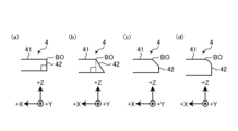
- FIG. 9 is a diagram illustrating a modification of the first to third embodiments.
- the incident surface 41 and the first side surface 42 intersect perpendicularly, as shown in FIG. 9(a).
- the entrance surface 41 and the first side surface 42 may intersect at an obtuse angle.
- the corner portion between the entrance surface 41 and the first side surface 42 may be chamfered.
- the corner portion between the entrance surface 41 and the first side surface 42 may be rounded.
Landscapes
- Physics & Mathematics (AREA)
- Health & Medical Sciences (AREA)
- General Physics & Mathematics (AREA)
- Life Sciences & Earth Sciences (AREA)
- General Health & Medical Sciences (AREA)
- High Energy & Nuclear Physics (AREA)
- Chemical & Material Sciences (AREA)
- Analytical Chemistry (AREA)
- Biochemistry (AREA)
- Immunology (AREA)
- Pathology (AREA)
- General Engineering & Computer Science (AREA)
- Molecular Biology (AREA)
- Spectroscopy & Molecular Physics (AREA)
- Engineering & Computer Science (AREA)
- Analysing Materials By The Use Of Radiation (AREA)
Abstract
An X-ray inspecting device 1 comprises: an X-ray radiating device 2 for radiating X-rays toward a measurement target object OB; a scintillator 4 for converting incident X-rays that have passed through the measurement target object OB into visible light; and an imaging device 5 for generating an X-ray image by imaging the visible light from the scintillator 4. The scintillator 4 is disposed such that a boundary BO between an incident surface 41 on which the X-rays are incident and a first side surface 42 intersecting the incident surface 41 is positioned within a radiation range SP of the X-rays. If the entire area of the first side surface 42 is divided into two areas, namely a first area Ar1 including the boundary BO and a second area Ar2 excluding the first area Ar1, the imaging device 5 is disposed facing the first side surface 42 and images the visible light emitted from the first area Ar1 among the entire area of the first side surface 42.
Description
本発明は、X線検査装置及びX線検査方法に関する。
The present invention relates to an X-ray inspection device and an X-ray inspection method.
従来、測定対象にX線を放射し、当該測定対象を介したX線をシンチレータにて可視光に変換(当該X線により蛍光発光して可視光を出射)し、当該可視光を撮像装置にて撮像してX線画像を生成するX線検査装置が知られている(例えば、特許文献1,2参照)。
特許文献1に記載のX線検査装置は、所謂、透過撮像型のX線検査装置である。具体的に、当該透過撮像型のX線検査装置は、シンチレータにおけるX線が入射する入射面と表裏をなす面から出射された可視光を撮像してX線画像を生成する。
特許文献2に記載のX線検査装置は、所謂、反射撮像型のX線検査装置である。具体的に、当該反射撮像型のX線検査装置は、シンチレータにおけるX線が入射する入射面から出射された可視光を撮像してX線画像を生成する。 Conventionally, X-rays are emitted to a measurement target, the X-rays that pass through the measurement target are converted into visible light by a scintillator (the X-rays emit fluorescence and the visible light is emitted), and the visible light is sent to an imaging device. An X-ray inspection apparatus that generates an X-ray image by capturing images is known (for example, see Patent Documents 1 and 2).
The X-ray inspection apparatus described in Patent Document 1 is a so-called transmission imaging type X-ray inspection apparatus. Specifically, the transmission imaging type X-ray inspection apparatus generates an X-ray image by capturing visible light emitted from a surface of the scintillator that is opposite to the incident surface on which X-rays enter.
The X-ray inspection apparatus described inPatent Document 2 is a so-called reflection imaging type X-ray inspection apparatus. Specifically, the reflection imaging type X-ray inspection apparatus generates an X-ray image by capturing visible light emitted from an incident surface on which X-rays enter a scintillator.
特許文献1に記載のX線検査装置は、所謂、透過撮像型のX線検査装置である。具体的に、当該透過撮像型のX線検査装置は、シンチレータにおけるX線が入射する入射面と表裏をなす面から出射された可視光を撮像してX線画像を生成する。
特許文献2に記載のX線検査装置は、所謂、反射撮像型のX線検査装置である。具体的に、当該反射撮像型のX線検査装置は、シンチレータにおけるX線が入射する入射面から出射された可視光を撮像してX線画像を生成する。 Conventionally, X-rays are emitted to a measurement target, the X-rays that pass through the measurement target are converted into visible light by a scintillator (the X-rays emit fluorescence and the visible light is emitted), and the visible light is sent to an imaging device. An X-ray inspection apparatus that generates an X-ray image by capturing images is known (for example, see Patent Documents 1 and 2).
The X-ray inspection apparatus described in Patent Document 1 is a so-called transmission imaging type X-ray inspection apparatus. Specifically, the transmission imaging type X-ray inspection apparatus generates an X-ray image by capturing visible light emitted from a surface of the scintillator that is opposite to the incident surface on which X-rays enter.
The X-ray inspection apparatus described in
しかしながら、特許文献1に記載の透過撮像型のX線検査装置では、X線がシンチレータに入射されると、当該シンチレータにて変換された可視光は、当該シンチレータの内部を進行するため、当該内部で吸収される。このため、入射面と表裏をなす面から出射される可視光の輝度が低いものとなり、X線画像が暗い画像となってしまう。また、粒子型のシンチレータを採用した場合には、当該シンチレータの内部を進行する可視光は、当該内部で散乱し易い。このため、X線画像は、不鮮明な画像となってしまう。
すなわち、特許文献1に記載の透過撮像型のX線検査装置では、X線画像が暗い画像や不鮮明な画像となってしまい、検査に適したX線画像を得ることが難しい、という問題がある。 However, in the transmission imaging type X-ray inspection apparatus described in Patent Document 1, when X-rays are incident on the scintillator, visible light converted by the scintillator travels inside the scintillator. It is absorbed by. For this reason, the brightness of the visible light emitted from the surfaces that are opposite to the entrance surface becomes low, resulting in a dark X-ray image. Furthermore, when a particle-type scintillator is employed, visible light traveling inside the scintillator is likely to be scattered within the scintillator. For this reason, the X-ray image becomes an unclear image.
That is, the transmission imaging type X-ray inspection apparatus described in Patent Document 1 has a problem in that the X-ray image becomes a dark image or an unclear image, making it difficult to obtain an X-ray image suitable for inspection. .
また、特許文献2に記載の反射撮像型のX線検査装置では、シンチレータにおけるX線が入射する入射面から出射された可視光を撮像装置に向けて進行させる必要があるため、当該シンチレータを測定対象に対して傾ける必要がある。このため、測定対象とシンチレータとの間の距離が比較的に大きくなる。その結果、X線画像に生じるボケ(半影)が大きくなり、当該X線画像は、不鮮明な画像となってしまう。
すなわち、特許文献2に記載の反射撮像型のX線検査装置では、X線画像が不鮮明な画像となってしまい、検査に適したX線画像を得ることが難しい、という問題がある。
そこで、検査に適したX線画像を得ることができる技術が要望されている。 In addition, in the reflection imaging type X-ray inspection device described inPatent Document 2, visible light emitted from the incident surface of the scintillator where X-rays enter must travel toward the imaging device, so the scintillator is measured. It needs to be tilted towards the target. Therefore, the distance between the measurement target and the scintillator becomes relatively large. As a result, the blur (penumbra) that occurs in the X-ray image becomes large, and the X-ray image becomes an unclear image.
That is, the reflection imaging type X-ray inspection apparatus described inPatent Document 2 has a problem in that the X-ray image becomes an unclear image and it is difficult to obtain an X-ray image suitable for inspection.
Therefore, there is a need for a technology that can obtain X-ray images suitable for examination.
すなわち、特許文献2に記載の反射撮像型のX線検査装置では、X線画像が不鮮明な画像となってしまい、検査に適したX線画像を得ることが難しい、という問題がある。
そこで、検査に適したX線画像を得ることができる技術が要望されている。 In addition, in the reflection imaging type X-ray inspection device described in
That is, the reflection imaging type X-ray inspection apparatus described in
Therefore, there is a need for a technology that can obtain X-ray images suitable for examination.
本発明は、上記に鑑みてなされたものであって、検査に適したX線画像を得ることができるX線検査装置及びX線検査方法を提供することを目的とする。
The present invention has been made in view of the above, and an object of the present invention is to provide an X-ray inspection apparatus and an X-ray inspection method that can obtain an X-ray image suitable for inspection.
上述した課題を解決し、目的を達成するために、本発明に係るX線検査装置は、測定対象に向けてX線を放射するX線放射装置と、前記測定対象を介して入射した前記X線を可視光に変換するシンチレータと、前記シンチレータからの前記可視光を撮像してX線画像を生成する撮像装置とを備え、前記シンチレータは、前記X線が入射する入射面と前記入射面に交差する第1の側面との境界が前記X線の放射範囲内に位置するように配置され、前記撮像装置は、前記第1の側面の全領域を、前記境界を含む第1の領域と、前記第1の領域を除く第2の領域との2つの領域に区画した場合に、前記第1の側面に対向するように配置されるとともに、前記第1の側面の全領域のうち前記第1の領域から出射される前記可視光を撮像する。
In order to solve the above-mentioned problems and achieve the objects, an X-ray inspection apparatus according to the present invention includes an X-ray emitting device that emits X-rays toward a measurement object, and an The scintillator includes a scintillator that converts radiation into visible light, and an imaging device that images the visible light from the scintillator to generate an X-ray image, and the scintillator has an incident surface on which the X-rays enter and an incident surface on which the X-rays enter. The imaging device is arranged such that the boundary with the intersecting first side surface is located within the radiation range of the X-ray, and the imaging device covers the entire area of the first side surface with the first area including the boundary; When partitioned into two regions, a second region excluding the first region, the first region is arranged so as to face the first side surface, and the first region out of the entire region of the first side surface is The visible light emitted from the region is imaged.
また、本発明に係るX線検査装置では、上記発明において、前記入射面の全領域を、前記境界を含む第3の領域と、前記第3の領域を除く第4の領域との2つの領域に区画した場合に、前記測定対象と前記シンチレータとの間に配置されるとともに、前記入射面の全領域のうち前記第4の領域に入射する前記X線を遮蔽するX線遮蔽部材をさらに備える。
Further, in the X-ray inspection apparatus according to the present invention, in the above invention, the entire area of the entrance surface is divided into two areas: a third area including the boundary and a fourth area excluding the third area. further comprising an X-ray shielding member that is disposed between the measurement target and the scintillator and that shields the X-rays that enter the fourth region of the entire region of the incident surface. .
また、本発明に係るX線検査装置では、上記発明において、前記シンチレータは、前記第1の側面と表裏をなす第2の側面と前記第1の側面との間の寸法が30μm以上、500μm以下に設定されている。
Further, in the X-ray inspection apparatus according to the present invention, in the above invention, the scintillator has a dimension between the first side surface and a second side surface that is opposite to the first side surface and is 30 μm or more and 500 μm or less. is set to .
また、本発明に係るX線検査装置では、上記発明において、前記X線画像を解析する画像解析装置をさらに備え、前記画像解析装置は、前記X線画像における前記X線の入射方向に沿う前記可視光の輝度分布に基づいて、前記測定対象に存在する異常箇所の特徴量を推定する。
Further, in the above invention, the X-ray inspection apparatus according to the present invention further includes an image analysis device that analyzes the X-ray image, and the image analysis device includes a Based on the luminance distribution of visible light, a feature quantity of an abnormal location existing in the measurement object is estimated.
また、本発明に係るX線検査装置では、上記発明において、前記X線放射装置及び前記シンチレータは、前記X線放射装置のX線焦点から前記測定対象までの距離をL1[mm]、前記X線焦点から前記シンチレータまでの距離をL2[mm]、及び前記X線焦点の直径をR[μm]とした場合に、(L2-L1)×R/L1で示される半影の幅が30μm以下となるように設置されている。
Further, in the X-ray inspection apparatus according to the present invention, in the above invention, the X-ray emitting device and the scintillator set a distance L1 [mm] from the X-ray focal point of the X-ray emitting device to the measurement object, and the X-ray When the distance from the line focus to the scintillator is L2 [mm], and the diameter of the X-ray focus is R [μm], the width of the penumbra represented by (L2-L1) x R/L1 is 30 μm or less It is set up so that.
また、本発明に係るX線検査装置では、上記発明において、前記測定対象を前記第1の側面の略垂直方向に、前記X線放射装置、前記シンチレータ、及び前記撮像装置に対して相対的に移動させる、または当該相対的な移動と停止とを繰り返す搬送装置をさらに備える。
Further, in the X-ray inspection apparatus according to the present invention, in the above invention, the measurement target is placed in a direction substantially perpendicular to the first side surface relative to the X-ray emitting device, the scintillator, and the imaging device. It further includes a conveying device that moves or repeats the relative movement and stopping.
また、本発明に係るX線検査方法は、シンチレータにおけるX線が入射する入射面と前記入射面に交差する第1の側面との境界がX線の放射範囲内に位置するように前記シンチレータを配置するシンチレータ配置工程と、前記第1の側面に対向するように撮像装置を配置する撮像装置配置工程と、X放射装置から測定対象に向けて前記X線を放射するX線放射工程と、前記測定対象を介した前記X線が前記シンチレータに入射し、前記シンチレータにて変換された可視光を前記撮像装置にて撮像してX線画像を生成する撮像工程とを備え、前記撮像工程では、前記第1の側面の全領域を、前記境界を含む第1の領域と、前記第1の領域を除く第2の領域との2つの領域に区画した場合に、前記第1の側面の全領域のうち前記第1の領域から出射される前記可視光を前記撮像装置にて撮像する。
Further, in the X-ray inspection method according to the present invention, the scintillator is arranged such that a boundary between an incident surface on which X-rays enter the scintillator and a first side surface that intersects the incident surface is located within the radiation range of the X-rays. an imaging device arranging step of arranging an imaging device to face the first side surface; an X-ray radiation step of radiating the X-rays from the X-ray device toward the measurement target; an imaging step in which the X-rays that have passed through the measurement object are incident on the scintillator, and the visible light converted by the scintillator is imaged by the imaging device to generate an X-ray image, and in the imaging step, When the entire area of the first side surface is divided into two areas, a first area including the boundary and a second area excluding the first area, the entire area of the first side surface The visible light emitted from the first region is imaged by the imaging device.
また、本発明に係るX線検査方法では、上記発明において、前記入射面の全領域を、前記境界を含む第3の領域と、前記第3の領域を除く第4の領域との2つの領域に区画した場合に、前記第4の領域に入射する前記X線を遮蔽するために、前記測定対象と前記シンチレータとの間に前記X線を遮蔽するX線遮蔽部材を配置するX線遮蔽部材配置工程をさらに備える。
Further, in the X-ray inspection method according to the present invention, in the above invention, the entire area of the entrance surface is divided into two areas: a third area including the boundary and a fourth area excluding the third area. an X-ray shielding member for disposing an X-ray shielding member for shielding the X-rays between the measurement object and the scintillator in order to shield the X-rays incident on the fourth region when the fourth region is divided into The method further includes a placement step.
また、本発明に係るX線検査方法では、上記発明において、前記X線画像を解析する画像解析工程をさらに備え、前記画像解析工程では、前記X線画像における前記X線の入射方向に沿う前記可視光の輝度分布に基づいて、前記測定対象に存在する異常箇所の特徴量を推定する。
The X-ray inspection method according to the present invention further includes an image analysis step of analyzing the X-ray image, and in the image analysis step, the Based on the luminance distribution of visible light, a feature quantity of an abnormal location existing in the measurement object is estimated.
また、本発明に係るX線検査方法では、上記発明において、前記X線放射装置と前記シンチレータとの位置関係を調整する位置関係調整工程をさらに備え、前記位置関係調整工程では、前記X線放射装置のX線焦点から前記測定対象までの距離をL1[mm]、前記X線焦点から前記シンチレータまでの距離をL2[mm]、及び前記X線焦点の直径をR[μm]とした場合に、(L2-L1)×R/L1で示される半影の幅が前記測定対象に対して検出すべき欠点の径の1/6以下となるように前記X線放射装置と前記シンチレータとの位置関係を調整する。
Further, in the above invention, the X-ray inspection method according to the present invention further includes a positional relationship adjustment step of adjusting the positional relationship between the X-ray emitting device and the scintillator, and in the positional relationship adjusting step, the X-ray radiation When the distance from the X-ray focus of the device to the measurement target is L1 [mm], the distance from the X-ray focus to the scintillator is L2 [mm], and the diameter of the X-ray focus is R [μm]. , (L2-L1)×R/L1 The position of the X-ray emitting device and the scintillator is such that the width of the penumbra is 1/6 or less of the diameter of the defect to be detected for the measurement object. Adjust relationships.
また、本発明に係るX線検査方法では、上記発明において、前記測定対象を前記第1の側面の略垂直方向に、前記X線放射装置、前記シンチレータ、及び前記撮像装置に対して相対的に移動させる、または当該相対的な移動と停止とを繰り返す搬送工程をさらに備える。
Further, in the X-ray inspection method according to the present invention, in the above invention, the measurement target is placed in a direction substantially perpendicular to the first side surface relative to the X-ray emitting device, the scintillator, and the imaging device. It further includes a conveying step of moving or repeating the relative movement and stopping.
本発明に係るX線検査装置及びX線検査方法によれば、検査に適したX線画像を得ることができる。
According to the X-ray inspection device and the X-ray inspection method according to the present invention, it is possible to obtain an X-ray image suitable for inspection.
以下に、図面を参照して、本発明を実施するための形態(以下、実施の形態)について説明する。なお、以下に説明する実施の形態によって本発明が限定されるものではない。さらに、図面の記載において、同一の部分には同一の符号を付している。
Hereinafter, modes for carrying out the present invention (hereinafter referred to as embodiments) will be described with reference to the drawings. Note that the present invention is not limited to the embodiments described below. Furthermore, in the description of the drawings, the same parts are denoted by the same reference numerals.
(実施の形態1)
〔X線検査装置の構成〕
図1は、実施の形態1に係るX線検査装置1を示す図である。
X線検査装置1は、フィルムや繊維等の測定対象OB(図1)にX線を放射し、当該測定対象OBを透過したX線を可視光に変換し、当該可視光を撮像してX線画像を生成する。そして、X線検査装置1は、当該X線画像を解析することにより、測定対象OBに混入している金属異物等の欠点DE(図3参照)の特徴量を推定する。
なお、測定対象OBとしては、フィルムや繊維に限らず、紙、樹脂、及び集積回路等を採用しても構わない。 (Embodiment 1)
[Configuration of X-ray inspection device]
FIG. 1 is a diagram showing an X-ray inspection apparatus 1 according to the first embodiment.
The X-ray inspection device 1 emits X-rays to a measurement object OB (FIG. 1) such as a film or fiber, converts the X-rays transmitted through the measurement object OB into visible light, images the visible light, and generates an X-ray image. Generate a line image. Then, the X-ray inspection apparatus 1 estimates the feature amount of the defect DE (see FIG. 3) such as a foreign metal object mixed in the measurement object OB by analyzing the X-ray image.
Note that the OB to be measured is not limited to films or fibers, but may also be paper, resin, integrated circuits, or the like.
このX線検査装置1は、図1に示すように、X線放射装置2と、搬送装置3と、シンチレータ4と、撮像装置5と、表示装置6と、制御装置7とを備える。
なお、以下では、X線検査装置1の構成を説明するにあたって、鉛直方向に沿う軸をZ軸とし、当該Z軸に直交する2つの軸をX軸及びY軸とする。図1では、Z軸は、上下方向に沿う軸である。また、X軸は、左右方向に沿う軸である。さらに、Y軸は、図1の紙面に直交する軸である。 As shown in FIG. 1, this X-ray inspection apparatus 1 includes anX-ray emitting device 2, a transport device 3, a scintillator 4, an imaging device 5, a display device 6, and a control device 7.
In addition, below, when explaining the structure of the X-ray inspection apparatus 1, the axis along the vertical direction will be referred to as the Z-axis, and the two axes orthogonal to the Z-axis will be referred to as the X-axis and the Y-axis. In FIG. 1, the Z axis is an axis along the vertical direction. Moreover, the X-axis is an axis along the left-right direction. Furthermore, the Y-axis is an axis perpendicular to the plane of the paper in FIG.
なお、以下では、X線検査装置1の構成を説明するにあたって、鉛直方向に沿う軸をZ軸とし、当該Z軸に直交する2つの軸をX軸及びY軸とする。図1では、Z軸は、上下方向に沿う軸である。また、X軸は、左右方向に沿う軸である。さらに、Y軸は、図1の紙面に直交する軸である。 As shown in FIG. 1, this X-ray inspection apparatus 1 includes an
In addition, below, when explaining the structure of the X-ray inspection apparatus 1, the axis along the vertical direction will be referred to as the Z-axis, and the two axes orthogonal to the Z-axis will be referred to as the X-axis and the Y-axis. In FIG. 1, the Z axis is an axis along the vertical direction. Moreover, the X-axis is an axis along the left-right direction. Furthermore, the Y-axis is an axis perpendicular to the plane of the paper in FIG.
X線放射装置2は、制御装置7による制御の下、X線焦点21(図1)から測定対象OBに向けて円錐状のX線ビーム(コーンビーム)を放射する。図1では、当該円錐状のX線ビームの放射範囲SPをドットで表現している。本実施の形態1では、X線放射装置2からのX線の放射方向は、-Z軸方向(図1中、下方向)である。
なお、X線放射装置2としては、密閉型でも開放型でもよく、また、ミリフォーカス型でもマイクロフォーカス型でも構わない。 TheX-ray emitting device 2 emits a conical X-ray beam (cone beam) from an X-ray focal point 21 (FIG. 1) toward the measurement object OB under the control of the control device 7. In FIG. 1, the radiation range SP of the conical X-ray beam is expressed by dots. In the first embodiment, the radiation direction of the X-rays from the X-ray radiation device 2 is the −Z-axis direction (downward in FIG. 1).
Note that theX-ray emitting device 2 may be of a closed type or an open type, and may be of a millifocus type or a microfocus type.
なお、X線放射装置2としては、密閉型でも開放型でもよく、また、ミリフォーカス型でもマイクロフォーカス型でも構わない。 The
Note that the
搬送装置3は、搬送ローラやベルトコンベア等を有し、制御装置7による制御の下、測定対象OBを保持しつつ、当該測定対象OBを搬送する。本実施の形態1では、測定対象OBの搬送方向は、-X軸方向(図1中、右方向)である。当該-X軸方向は、後述する第1の側面42の略垂直方向である。
The conveyance device 3 includes a conveyance roller, a belt conveyor, etc., and conveys the measurement target OB while holding the measurement target OB under the control of the control device 7. In the first embodiment, the transport direction of the measurement target OB is the -X axis direction (rightward in FIG. 1). The −X-axis direction is approximately perpendicular to the first side surface 42, which will be described later.
シンチレータ4は、図1に示すように、平面視矩形状の板体で構成され、板面がXY平面に略平行な姿勢で測定対象OBに対して-Z軸側に配置されている。そして、シンチレータ4は、測定対象OBを透過した後に入射したX線を可視光に変換(当該X線により蛍光発光)する。
ここで、シンチレータ4において、+Z軸側(図1中、上方側)の板面は、測定対象OBを透過したX線が入射し、本発明に係る入射面41(図1)に相当する。また、シンチレータ4において、-X軸側の側面は、入射面41に交差し、本発明に係る第1の側面42(図1)に相当する。
なお、シンチレータ4としては、粒子型でも単結晶型でも構わない。 As shown in FIG. 1, thescintillator 4 is composed of a plate having a rectangular shape in plan view, and is disposed on the −Z-axis side with respect to the measurement object OB with the plate surface substantially parallel to the XY plane. Then, the scintillator 4 converts the incident X-rays after passing through the measurement object OB into visible light (fluorescence is emitted by the X-rays).
Here, in thescintillator 4, the plate surface on the +Z-axis side (upper side in FIG. 1) is where the X-rays transmitted through the measurement object OB enter, and corresponds to the entrance surface 41 (FIG. 1) according to the present invention. Furthermore, in the scintillator 4, the side surface on the -X axis side intersects the incident surface 41 and corresponds to the first side surface 42 (FIG. 1) according to the present invention.
Note that thescintillator 4 may be of either a particle type or a single crystal type.
ここで、シンチレータ4において、+Z軸側(図1中、上方側)の板面は、測定対象OBを透過したX線が入射し、本発明に係る入射面41(図1)に相当する。また、シンチレータ4において、-X軸側の側面は、入射面41に交差し、本発明に係る第1の側面42(図1)に相当する。
なお、シンチレータ4としては、粒子型でも単結晶型でも構わない。 As shown in FIG. 1, the
Here, in the
Note that the
撮像装置5は、入射した光を受光して電気信号に変換するCCD(Charge Coupled Device)またはCMOS(Complementary Metal Oxide Semiconductor)等の撮像素子を含み、シンチレータ4からの可視光を撮像してX線画像を生成するカメラである。そして、撮像装置5は、生成したX線画像のデータを制御装置7に出力する。
なお、撮像装置5としては、ラインセンサカメラでも、エリアセンサカメラでも、時間遅延積分型カメラでも構わない。 Theimaging device 5 includes an imaging element such as a CCD (Charge Coupled Device) or a CMOS (Complementary Metal Oxide Semiconductor) that receives incident light and converts it into an electrical signal, and images the visible light from the scintillator 4 to generate X-rays. It is a camera that generates images. The imaging device 5 then outputs the generated X-ray image data to the control device 7.
Note that theimaging device 5 may be a line sensor camera, an area sensor camera, or a time delay and integration type camera.
なお、撮像装置5としては、ラインセンサカメラでも、エリアセンサカメラでも、時間遅延積分型カメラでも構わない。 The
Note that the
表示装置6は、液晶または有機EL(Electro Luminescence)等を用いた表示ディスプレイで構成され、制御装置7による制御の下、X線画像等の各種の画像を表示する。
The display device 6 is configured with a display using liquid crystal or organic EL (Electro Luminescence), and displays various images such as X-ray images under the control of the control device 7.
制御装置7は、X線検査装置1全体の動作を統括的に制御する。この制御装置7は、図1に示すように、プロセッサ71と、記憶部72と、入力部73とを備える。
プロセッサ71は、CPU(Central Processing Unit)やMPU(Micro Processing Unit)等のコントローラによって、記憶部72に記憶された各種のプログラムが実行されることにより実現され、X線検査装置1全体の動作を制御する。
なお、プロセッサ71としては、CPUやMPUに限らず、ASIC(Application Specific Integrated Circuit)やFPGA(Field-Programmable Gate Array)等の集積回路によって構成されても構わない。当該プロセッサ71の機能については、後述する「X線検査方法」において説明する。 The control device 7 centrally controls the operation of the entire X-ray inspection apparatus 1 . As shown in FIG. 1, the control device 7 includes aprocessor 71, a storage section 72, and an input section 73.
Theprocessor 71 is realized by executing various programs stored in the storage section 72 by a controller such as a CPU (Central Processing Unit) or an MPU (Micro Processing Unit), and controls the overall operation of the X-ray inspection apparatus 1. Control.
Note that theprocessor 71 is not limited to a CPU or an MPU, and may be configured by an integrated circuit such as an ASIC (Application Specific Integrated Circuit) or an FPGA (Field-Programmable Gate Array). The functions of the processor 71 will be explained in "X-ray inspection method" described later.
プロセッサ71は、CPU(Central Processing Unit)やMPU(Micro Processing Unit)等のコントローラによって、記憶部72に記憶された各種のプログラムが実行されることにより実現され、X線検査装置1全体の動作を制御する。
なお、プロセッサ71としては、CPUやMPUに限らず、ASIC(Application Specific Integrated Circuit)やFPGA(Field-Programmable Gate Array)等の集積回路によって構成されても構わない。当該プロセッサ71の機能については、後述する「X線検査方法」において説明する。 The control device 7 centrally controls the operation of the entire X-ray inspection apparatus 1 . As shown in FIG. 1, the control device 7 includes a
The
Note that the
記憶部72は、プロセッサ71が実行する各種のプログラムの他、当該プロセッサ71が処理を行うときに必要なデータ等を記憶する。
入力部73は、作業者によるユーザ操作を受け付けるボタン、スイッチ、タッチパネル等で構成され、当該ユーザ操作に応じた操作信号をプロセッサ71に出力する。なお、入力部73の機能の一部または全部がタッチパネルとして表示装置6の表示画面に配置されても構わない。 The storage unit 72 stores various programs executed by theprocessor 71 as well as data necessary for the processor 71 to perform processing.
The input unit 73 includes buttons, switches, touch panels, etc. that accept user operations by a worker, and outputs operation signals to theprocessor 71 in accordance with the user operations. Note that part or all of the functions of the input unit 73 may be arranged on the display screen of the display device 6 as a touch panel.
入力部73は、作業者によるユーザ操作を受け付けるボタン、スイッチ、タッチパネル等で構成され、当該ユーザ操作に応じた操作信号をプロセッサ71に出力する。なお、入力部73の機能の一部または全部がタッチパネルとして表示装置6の表示画面に配置されても構わない。 The storage unit 72 stores various programs executed by the
The input unit 73 includes buttons, switches, touch panels, etc. that accept user operations by a worker, and outputs operation signals to the
〔X線検査方法〕
次に、上述したX線検査装置1を用いたX線検査方法について説明する。
図2は、X線検査方法を示すフローチャートである。
先ず、作業者は、X線検査装置1の初期設定を行う(ステップS1)。
図3は、ステップS1を説明する図である。具体的に、図3は、X線放射装置2、測定対象OB、及びシンチレータ4の位置関係を示す図である。図3において、符号「R」は、X線焦点21の直径[μm]である。また、符号「L1」は、X線焦点21から測定対象OBまでの距離[mm]である。さらに、符号「L2」は、X線焦点21からシンチレータ4までの距離[mm]である。また、符号「r」は、半影(ボケ)SHの幅[μm]である。 [X-ray inspection method]
Next, an X-ray inspection method using the above-mentioned X-ray inspection apparatus 1 will be explained.
FIG. 2 is a flowchart showing the X-ray inspection method.
First, an operator performs initial settings of the X-ray inspection apparatus 1 (step S1).
FIG. 3 is a diagram illustrating step S1. Specifically, FIG. 3 is a diagram showing the positional relationship among theX-ray emitting device 2, the measurement object OB, and the scintillator 4. In FIG. 3, the symbol "R" is the diameter [μm] of the X-ray focal point 21. Further, the symbol “L1” is the distance [mm] from the X-ray focal point 21 to the measurement object OB. Furthermore, the symbol "L2" is the distance [mm] from the X-ray focal point 21 to the scintillator 4. Further, the symbol “r” is the width [μm] of the penumbra (blur) SH.
次に、上述したX線検査装置1を用いたX線検査方法について説明する。
図2は、X線検査方法を示すフローチャートである。
先ず、作業者は、X線検査装置1の初期設定を行う(ステップS1)。
図3は、ステップS1を説明する図である。具体的に、図3は、X線放射装置2、測定対象OB、及びシンチレータ4の位置関係を示す図である。図3において、符号「R」は、X線焦点21の直径[μm]である。また、符号「L1」は、X線焦点21から測定対象OBまでの距離[mm]である。さらに、符号「L2」は、X線焦点21からシンチレータ4までの距離[mm]である。また、符号「r」は、半影(ボケ)SHの幅[μm]である。 [X-ray inspection method]
Next, an X-ray inspection method using the above-mentioned X-ray inspection apparatus 1 will be explained.
FIG. 2 is a flowchart showing the X-ray inspection method.
First, an operator performs initial settings of the X-ray inspection apparatus 1 (step S1).
FIG. 3 is a diagram illustrating step S1. Specifically, FIG. 3 is a diagram showing the positional relationship among the
ここで、X線検査における半影SHについて説明する。
X線検査において、測定対象OBからシンチレータ4までの距離(L2-L1)を大きくし、放射されたX線による当該測定対象OBに混入している金属異物等の欠点DEの影を幾何学的に大きくした場合には、微小な欠点DEの検出感度が低くなってしまう。
具体的に、X線焦点21は、有限の直径R[μm]を有している。このため、本来、欠点DEの影となるべき領域にX線が入り込んでしまい、半影SH(図3)が生じる。すなわち、本来、欠点DEの影となる部分に半影SHが生じることにより、当該欠点DEを高精度に検出することが難しくなる。 Here, penumbra SH in X-ray examination will be explained.
In X-ray inspection, the distance (L2-L1) from the measurement target OB to thescintillator 4 is increased, and the shadow of defects DE such as metal foreign objects mixed in the measurement target OB due to the emitted X-rays is geometrically If it is made larger than that, the detection sensitivity for minute defects DE will become low.
Specifically, the X-rayfocal point 21 has a finite diameter R [μm]. For this reason, X-rays enter the region that should originally be the shadow of the defect DE, resulting in a penumbra SH (FIG. 3). That is, since the penumbra SH occurs in a portion that would normally be a shadow of the defect DE, it becomes difficult to detect the defect DE with high accuracy.
X線検査において、測定対象OBからシンチレータ4までの距離(L2-L1)を大きくし、放射されたX線による当該測定対象OBに混入している金属異物等の欠点DEの影を幾何学的に大きくした場合には、微小な欠点DEの検出感度が低くなってしまう。
具体的に、X線焦点21は、有限の直径R[μm]を有している。このため、本来、欠点DEの影となるべき領域にX線が入り込んでしまい、半影SH(図3)が生じる。すなわち、本来、欠点DEの影となる部分に半影SHが生じることにより、当該欠点DEを高精度に検出することが難しくなる。 Here, penumbra SH in X-ray examination will be explained.
In X-ray inspection, the distance (L2-L1) from the measurement target OB to the
Specifically, the X-ray
ところで、半影SHは、欠点DEの両端部で発生する。このため、欠点DEの影は、本来よりも2×r分だけ小さくなる。ここで、半影SHの幅rは、(L2-L1)×R/L1で示される。
本願の発明者は、鋭意検討を進めた結果、安定的に欠点DEを検出するためには、半影SHの幅rを欠点DEの径の1/6以下にすることが必要であることを見出した。本実施の形態1において、欠点DEの径は、30μm以上、200μm以下である。
そして、作業者は、ステップS1において、測定対象OBに対して検出すべき欠点DEの径を180μm程度とし、距離L1,L2を調整することにより、半影SHの幅rが当該180μmの1/6(30μm)以下となるように設定する。 Incidentally, the penumbra SH occurs at both ends of the defect DE. Therefore, the shadow of the defect DE becomes smaller by 2×r than originally. Here, the width r of the penumbra SH is expressed as (L2-L1)×R/L1.
As a result of intensive studies, the inventor of the present application found that in order to stably detect the defect DE, it is necessary to make the width r of the penumbra SH 1/6 or less of the diameter of the defect DE. I found it. In the first embodiment, the diameter of the defect DE is 30 μm or more and 200 μm or less.
Then, in step S1, the operator sets the diameter of the defect DE to be detected in the measurement target OB to about 180 μm, and adjusts the distances L1 and L2 so that the width r of the penumbra SH is 1/1/2 of the 180 μm. 6 (30 μm) or less.
また、作業者は、ステップS1において、シンチレータ4における入射面41と第1の側面42との境界BO(図1)がX線の放射範囲SP内に位置するように当該シンチレータ4を配置する。
さらに、作業者は、ステップS1において、第1の側面42に対向するように撮像装置5を配置する。
以上のように、ステップS1は、本発明に係る位置関係調整工程、シンチレータ配置工程、及び撮像装置配置工程に相当する。 Further, in step S1, the operator arranges thescintillator 4 so that the boundary BO (FIG. 1) between the entrance surface 41 and the first side surface 42 of the scintillator 4 is located within the X-ray radiation range SP.
Furthermore, the operator arranges theimaging device 5 so as to face the first side surface 42 in step S1.
As described above, step S1 corresponds to the positional relationship adjustment step, scintillator placement step, and imaging device placement step according to the present invention.
さらに、作業者は、ステップS1において、第1の側面42に対向するように撮像装置5を配置する。
以上のように、ステップS1は、本発明に係る位置関係調整工程、シンチレータ配置工程、及び撮像装置配置工程に相当する。 Further, in step S1, the operator arranges the
Furthermore, the operator arranges the
As described above, step S1 corresponds to the positional relationship adjustment step, scintillator placement step, and imaging device placement step according to the present invention.
ステップS1の後、作業者は、入力部73に対して、X線検査を開始する操作を行う。これにより、プロセッサ71は、以下に示す処理を実行する。
先ず、プロセッサ71は、搬送装置3を動作させ、測定対象OBを所定の速度で搬送する(ステップS2:搬送工程)。
ステップS2の後、プロセッサ71は、X線放射装置2を動作させる。そして、X線放射装置2は、測定対象OBに向けてX線を放射する(ステップS3:X線放射工程)。 After step S1, the operator performs an operation on the input unit 73 to start the X-ray examination. As a result, theprocessor 71 executes the processing described below.
First, theprocessor 71 operates the transport device 3 to transport the measurement target OB at a predetermined speed (step S2: transport process).
After step S2, theprocessor 71 operates the X-ray emitting device 2. Then, the X-ray emitting device 2 emits X-rays toward the measurement target OB (step S3: X-ray emitting step).
先ず、プロセッサ71は、搬送装置3を動作させ、測定対象OBを所定の速度で搬送する(ステップS2:搬送工程)。
ステップS2の後、プロセッサ71は、X線放射装置2を動作させる。そして、X線放射装置2は、測定対象OBに向けてX線を放射する(ステップS3:X線放射工程)。 After step S1, the operator performs an operation on the input unit 73 to start the X-ray examination. As a result, the
First, the
After step S2, the
ステップS3の後、プロセッサ71は、撮像装置5を動作させる。そして、撮像装置5は、測定対象OBを介したX線がシンチレータ4に入射し、当該シンチレータ4にて変換された可視光を撮像してX線画像を生成する(ステップS4:撮像工程)。また、撮像装置5は、当該生成したX線画像のデータを制御装置7に出力する。
ここで、第1の側面42の全領域を、境界BOを含む第1の領域Ar1(図4参照)と、当該第1の領域Ar1を除く第2の領域Ar2(図4参照)との2つの領域に区画した場合を想定する。この場合には、ステップS4では、第1の側面42の全領域のうち第1の領域Ar1から出射される可視光を撮像装置5にて撮像する。すなわち、ステップS4では、第1の側面42の全領域のうち、境界BO近傍の領域(第1の領域Ar1)から出射される可視光を撮像装置5にて撮像する。 After step S3, theprocessor 71 operates the imaging device 5. Then, the imaging device 5 generates an X-ray image by imaging visible light that is incident on the scintillator 4 through the measurement target OB and converted by the scintillator 4 (step S4: imaging step). Further, the imaging device 5 outputs data of the generated X-ray image to the control device 7.
Here, the entire area of thefirst side surface 42 is divided into a first area Ar1 (see FIG. 4) including the boundary BO and a second area Ar2 (see FIG. 4) excluding the first area Ar1. Assume that the area is partitioned into two areas. In this case, in step S4, visible light emitted from the first area Ar1 of the entire area of the first side surface 42 is imaged by the imaging device 5. That is, in step S4, visible light emitted from the area near the boundary BO (first area Ar1) out of the entire area of the first side surface 42 is imaged by the imaging device 5.
ここで、第1の側面42の全領域を、境界BOを含む第1の領域Ar1(図4参照)と、当該第1の領域Ar1を除く第2の領域Ar2(図4参照)との2つの領域に区画した場合を想定する。この場合には、ステップS4では、第1の側面42の全領域のうち第1の領域Ar1から出射される可視光を撮像装置5にて撮像する。すなわち、ステップS4では、第1の側面42の全領域のうち、境界BO近傍の領域(第1の領域Ar1)から出射される可視光を撮像装置5にて撮像する。 After step S3, the
Here, the entire area of the
ステップS4の後、プロセッサ71は、ステップS4にて生成されたX線画像のデータを撮像装置5から取得し、当該X線画像を解析する(ステップS5:画像解析工程)。この後、プロセッサ71は、ステップS2に戻る。
図4は、ステップS5を説明する図である。具体的に、図4の(a)は、測定対象OBに混入している欠点DEの厚みが大きい場合または当該欠点DEの密度が高い場合でのX線画像F1を示している。図4の(b)は、測定対象OBに混入している欠点DEの厚みが小さい場合または当該欠点DEの密度が低い場合でのX線画像F2を示している。なお、図4では、X線による欠点DEの影となる領域ArS1,ArS2内において、当該X線が変換された可視光の輝度が低いほど、ドットの密度を高くしている。また、図4では、説明の便宜上、第1の側面42において、領域ArS1,ArS2以外の領域については、当該ドットを付していない。 After step S4, theprocessor 71 acquires data of the X-ray image generated in step S4 from the imaging device 5, and analyzes the X-ray image (step S5: image analysis step). After this, the processor 71 returns to step S2.
FIG. 4 is a diagram illustrating step S5. Specifically, (a) of FIG. 4 shows the X-ray image F1 when the thickness of the defect DE included in the measurement object OB is large or when the density of the defect DE is high. (b) of FIG. 4 shows an X-ray image F2 when the thickness of the defect DE included in the measurement object OB is small or when the density of the defect DE is low. In FIG. 4, in the regions ArS1 and ArS2 shadowed by the defect DE caused by the X-rays, the lower the brightness of the visible light into which the X-rays are converted, the higher the dot density is. Further, in FIG. 4, for convenience of explanation, the dots are not attached to areas other than the areas ArS1 and ArS2 on thefirst side surface 42.
図4は、ステップS5を説明する図である。具体的に、図4の(a)は、測定対象OBに混入している欠点DEの厚みが大きい場合または当該欠点DEの密度が高い場合でのX線画像F1を示している。図4の(b)は、測定対象OBに混入している欠点DEの厚みが小さい場合または当該欠点DEの密度が低い場合でのX線画像F2を示している。なお、図4では、X線による欠点DEの影となる領域ArS1,ArS2内において、当該X線が変換された可視光の輝度が低いほど、ドットの密度を高くしている。また、図4では、説明の便宜上、第1の側面42において、領域ArS1,ArS2以外の領域については、当該ドットを付していない。 After step S4, the
FIG. 4 is a diagram illustrating step S5. Specifically, (a) of FIG. 4 shows the X-ray image F1 when the thickness of the defect DE included in the measurement object OB is large or when the density of the defect DE is high. (b) of FIG. 4 shows an X-ray image F2 when the thickness of the defect DE included in the measurement object OB is small or when the density of the defect DE is low. In FIG. 4, in the regions ArS1 and ArS2 shadowed by the defect DE caused by the X-rays, the lower the brightness of the visible light into which the X-rays are converted, the higher the dot density is. Further, in FIG. 4, for convenience of explanation, the dots are not attached to areas other than the areas ArS1 and ArS2 on the
ところで、欠点DEが混入している場合には、図4に示すように、当該欠点DEによってX線が吸収され、当該欠点DEの影となる領域ArS1,ArS2が生じる。当該領域ArS1,ArS2において、入射面41に近い領域では、欠点DEによるX線の吸収により、当該X線が変換された可視光の輝度は、低いものとなる。そして、当該領域ArS1,ArS2において、-Z方向に向かうにしたがって、当該領域ArS1,ArS2以外の領域からの可視光の影響により、徐々に可視光の輝度が高くなり、最終的に、当該領域ArS1,ArS2以外の領域の可視光の輝度と略同一となる。
By the way, when a defect DE is mixed, as shown in FIG. 4, X-rays are absorbed by the defect DE, and regions ArS1 and ArS2 are created which are shadows of the defect DE. In the regions ArS1 and ArS2, in the region close to the entrance surface 41, the brightness of visible light converted from the X-rays becomes low due to absorption of the X-rays by the defect DE. In the areas ArS1 and ArS2, the brightness of the visible light gradually increases as it goes in the -Z direction due to the influence of visible light from areas other than the areas ArS1 and ArS2, and finally, the brightness of the visible light increases in the -Z direction. , ArS2 is approximately the same as the brightness of visible light in the area other than ArS2.
ここで、図4の(a)と図4の(b)とを比較して分かるように、欠点DEの厚みや密度が異なる場合には、領域ArS1,ArS2のZ軸方向の長さ等のZ軸方向に沿う可視光の輝度分布が異なるものとなる。具体的に、領域ArS1のZ軸方向の長さは、領域ArS2のZ軸方向の長さよりも長い。すなわち、欠点DEの厚みや密度等の特徴量と、X線画像におけるZ軸方向(X線の入射方向)に沿う可視光の輝度分布とには、相関関係がある。そして、記憶部72には、当該相関関係を示す相関情報が記憶されている。
なお、このZ軸方向に沿う可視光の輝度分布は、欠点DEのY軸方向の長さにも依存する。このため、記憶部72に記憶される相関情報を構成する特徴量に、欠点DEの厚みや密度の他、当該欠点DEのY軸方向の長さを含めても構わない。 Here, as can be seen by comparing FIG. 4(a) and FIG. 4(b), when the thickness and density of the defect DE are different, the length of the regions ArS1 and ArS2 in the Z-axis direction, etc. The brightness distribution of visible light along the Z-axis direction becomes different. Specifically, the length of the region ArS1 in the Z-axis direction is longer than the length of the region ArS2 in the Z-axis direction. That is, there is a correlation between the feature quantities such as the thickness and density of the defect DE and the luminance distribution of visible light along the Z-axis direction (the incident direction of the X-rays) in the X-ray image. The storage unit 72 stores correlation information indicating the correlation.
Note that the luminance distribution of visible light along the Z-axis direction also depends on the length of the defect DE in the Y-axis direction. Therefore, in addition to the thickness and density of the defect DE, the length of the defect DE in the Y-axis direction may be included in the feature amount constituting the correlation information stored in the storage unit 72.
ステップS5では、プロセッサ71は、ステップS4にて生成されたX線画像から、Z軸方向に沿う可視光の輝度分布(受光量プロファイル)を取得し、記憶部72に記憶された相関情報を参照し、当該輝度分布に対応する特徴量を推定する。すなわち、制御装置7は、本発明に係る画像解析装置に相当する。
In step S5, the processor 71 obtains the luminance distribution of visible light (received light amount profile) along the Z-axis direction from the X-ray image generated in step S4, and refers to the correlation information stored in the storage unit 72. Then, the feature amount corresponding to the luminance distribution is estimated. That is, the control device 7 corresponds to an image analysis device according to the present invention.
ここで、シンチレータ4におけるZ軸方向(図4中、上下方向)の長さ寸法は、ステップS5において、受光量プロファイルを取得するために、200μm以上であることが好ましい。また、シンチレータ4におけるY軸方向(図4中、左右方向)の長さ寸法は、60~100mm程度である。
Here, the length dimension of the scintillator 4 in the Z-axis direction (vertical direction in FIG. 4) is preferably 200 μm or more in order to obtain the received light amount profile in step S5. Further, the length of the scintillator 4 in the Y-axis direction (left-right direction in FIG. 4) is about 60 to 100 mm.
以上説明した本実施の形態1によれば、以下の効果を奏する。
本実施の形態1に係るX線検査装置1では、シンチレータ4は、境界BOをX線の放射範囲SP内に位置するように配置されている。また、撮像装置5は、第1の側面42に対向するように配置されるとともに、当該第1の側面42の全領域のうち境界BOを含む第1の領域Ar1から出射される可視光を撮像する。
すなわち、撮像装置5は、特許文献1に記載の透過撮像型のX線検査装置のようにシンチレータを透過した可視光を撮像するのではなく、第1の側面42における第1の領域Ar1から出射された可視光を撮像する。言い換えれば、撮像装置5は、シンチレータ4の内部での吸収や散乱の影響が少ない可視光を撮像する。このため、明るく、かつ、鮮明なX線画像を生成することができる。
また、特許文献2に記載の反射撮像型のX線検査装置のようにシンチレータを測定対象に対して傾ける必要がないため、シンチレータ4を測定対象OBに近付けることができる。このため、X線画像に生じる半影SHの幅rを小さくすることができ、鮮明なX線画像を生成することができる。
以上のことから、本実施の形態1に係るX線検査装置1によれば、検査に適したX線画像を得ることができる。 According to the first embodiment described above, the following effects are achieved.
In the X-ray inspection apparatus 1 according to the first embodiment, thescintillator 4 is arranged so that the boundary BO is located within the X-ray radiation range SP. The imaging device 5 is arranged to face the first side surface 42 and captures an image of visible light emitted from a first region Ar1 including the boundary BO among the entire region of the first side surface 42. do.
That is, theimaging device 5 does not image the visible light that has passed through the scintillator like the transmission imaging type X-ray inspection device described in Patent Document 1, but instead captures the visible light that is emitted from the first region Ar1 on the first side surface 42. image the visible light emitted. In other words, the imaging device 5 images visible light that is less affected by absorption and scattering inside the scintillator 4. Therefore, a bright and clear X-ray image can be generated.
Further, unlike the reflection imaging type X-ray inspection apparatus described inPatent Document 2, there is no need to tilt the scintillator with respect to the measurement object, so the scintillator 4 can be brought closer to the measurement object OB. Therefore, the width r of the penumbra SH occurring in the X-ray image can be reduced, and a clear X-ray image can be generated.
From the above, according to the X-ray inspection apparatus 1 according to the first embodiment, it is possible to obtain an X-ray image suitable for inspection.
本実施の形態1に係るX線検査装置1では、シンチレータ4は、境界BOをX線の放射範囲SP内に位置するように配置されている。また、撮像装置5は、第1の側面42に対向するように配置されるとともに、当該第1の側面42の全領域のうち境界BOを含む第1の領域Ar1から出射される可視光を撮像する。
すなわち、撮像装置5は、特許文献1に記載の透過撮像型のX線検査装置のようにシンチレータを透過した可視光を撮像するのではなく、第1の側面42における第1の領域Ar1から出射された可視光を撮像する。言い換えれば、撮像装置5は、シンチレータ4の内部での吸収や散乱の影響が少ない可視光を撮像する。このため、明るく、かつ、鮮明なX線画像を生成することができる。
また、特許文献2に記載の反射撮像型のX線検査装置のようにシンチレータを測定対象に対して傾ける必要がないため、シンチレータ4を測定対象OBに近付けることができる。このため、X線画像に生じる半影SHの幅rを小さくすることができ、鮮明なX線画像を生成することができる。
以上のことから、本実施の形態1に係るX線検査装置1によれば、検査に適したX線画像を得ることができる。 According to the first embodiment described above, the following effects are achieved.
In the X-ray inspection apparatus 1 according to the first embodiment, the
That is, the
Further, unlike the reflection imaging type X-ray inspection apparatus described in
From the above, according to the X-ray inspection apparatus 1 according to the first embodiment, it is possible to obtain an X-ray image suitable for inspection.
ところで、特許文献2に記載の反射撮像型のX線検査装置では、撮像装置は、シンチレータの入射面を撮像する必要がある。このため、撮像装置の撮像視野に測定対象が入り、当該測定対象によりシンチレータの入射面が遮られ易く、当該撮像装置の設置位置の設定が難しいものとなる。
これに対して、本実施の形態1に係るX線検査装置1では、撮像装置5は、第1の側面42に対向するように配置され、当該第1の側面42における第1の領域Ar1から出射される可視光を撮像する。このため、測定対象により当該第1の領域Ar1が遮られることがなく、撮像装置5を容易に設置することができる。また、撮像装置5を第1の側面42に対向するように設置することで、当該撮像装置5は、X線による被ばくがない状態となる。このため、撮像装置5の長寿命化を図ることができる。 By the way, in the reflection imaging type X-ray inspection apparatus described inPatent Document 2, the imaging device needs to image the incident surface of the scintillator. Therefore, the object to be measured enters the field of view of the imaging device, and the incident surface of the scintillator is likely to be blocked by the object, making it difficult to set the installation position of the imaging device.
On the other hand, in the X-ray inspection apparatus 1 according to the first embodiment, theimaging device 5 is arranged so as to face the first side surface 42, and the imaging device 5 is arranged to face the first side surface 42, and The emitted visible light is imaged. Therefore, the first area Ar1 is not obstructed by the object to be measured, and the imaging device 5 can be easily installed. Further, by installing the imaging device 5 so as to face the first side surface 42, the imaging device 5 is not exposed to X-rays. Therefore, the life of the imaging device 5 can be extended.
これに対して、本実施の形態1に係るX線検査装置1では、撮像装置5は、第1の側面42に対向するように配置され、当該第1の側面42における第1の領域Ar1から出射される可視光を撮像する。このため、測定対象により当該第1の領域Ar1が遮られることがなく、撮像装置5を容易に設置することができる。また、撮像装置5を第1の側面42に対向するように設置することで、当該撮像装置5は、X線による被ばくがない状態となる。このため、撮像装置5の長寿命化を図ることができる。 By the way, in the reflection imaging type X-ray inspection apparatus described in
On the other hand, in the X-ray inspection apparatus 1 according to the first embodiment, the
また、本実施の形態1に係るX線検査装置1では、X線放射装置2及びシンチレータ4は、半影SHの幅rが測定対象OBに対して検出すべき欠点DEの径である180μmの1/6(30μm)以下となるように設置されている。
このため、安定的に欠点DEを検出することができる。 In the X-ray inspection apparatus 1 according to the first embodiment, theX-ray radiation apparatus 2 and the scintillator 4 have a width r of the penumbra SH of 180 μm, which is the diameter of the defect DE to be detected with respect to the measurement object OB. It is installed so that it is 1/6 (30 μm) or less.
Therefore, the defect DE can be detected stably.
このため、安定的に欠点DEを検出することができる。 In the X-ray inspection apparatus 1 according to the first embodiment, the
Therefore, the defect DE can be detected stably.
また、本実施の形態1に係るX線検査装置1では、プロセッサ71は、X線画像F1,F2におけるX線の入射方向に沿う可視光の輝度分布(受光量プロファイル)に基づいて、測定対象OBに存在する欠点DEの特徴量を推定する。
このため、簡単な処理で容易に欠点DEの特徴量(厚さや密度)を推定することができる。 Further, in the X-ray inspection apparatus 1 according to the first embodiment, theprocessor 71 determines the measurement target based on the luminance distribution (received light amount profile) of visible light along the incident direction of the X-rays in the X-ray images F1 and F2. Estimate the feature amount of defect DE existing in OB.
Therefore, the feature amounts (thickness and density) of the defect DE can be easily estimated with simple processing.
このため、簡単な処理で容易に欠点DEの特徴量(厚さや密度)を推定することができる。 Further, in the X-ray inspection apparatus 1 according to the first embodiment, the
Therefore, the feature amounts (thickness and density) of the defect DE can be easily estimated with simple processing.
(実施の形態2)
次に、本実施の形態2について説明する。
以下の説明では、上述した実施の形態1と同様の構成には同一符号を付し、その詳細な説明は省略または簡略化する。
図5は、図1に対応した図であって、実施の形態2に係るX線検査装置1Aを示す図である。なお、図5では、説明の便宜上、搬送装置3、撮像装置5、表示装置6、及び制御装置7の図示を省略している。
本実施の形態2に係るX線検査装置1Aでは、図5に示すように、上述した実施の形態1において説明したX線検査装置1に対して、X線遮蔽部材8が追加されている。 (Embodiment 2)
Next,Embodiment 2 will be described.
In the following description, the same components as those in the first embodiment described above are denoted by the same reference numerals, and detailed description thereof will be omitted or simplified.
FIG. 5 is a diagram corresponding to FIG. 1, and is a diagram showing anX-ray inspection apparatus 1A according to the second embodiment. In addition, in FIG. 5, illustration of the conveyance device 3, the imaging device 5, the display device 6, and the control device 7 is omitted for convenience of explanation.
In theX-ray inspection apparatus 1A according to the second embodiment, as shown in FIG. 5, an X-ray shielding member 8 is added to the X-ray inspection apparatus 1 described in the above-described first embodiment.
次に、本実施の形態2について説明する。
以下の説明では、上述した実施の形態1と同様の構成には同一符号を付し、その詳細な説明は省略または簡略化する。
図5は、図1に対応した図であって、実施の形態2に係るX線検査装置1Aを示す図である。なお、図5では、説明の便宜上、搬送装置3、撮像装置5、表示装置6、及び制御装置7の図示を省略している。
本実施の形態2に係るX線検査装置1Aでは、図5に示すように、上述した実施の形態1において説明したX線検査装置1に対して、X線遮蔽部材8が追加されている。 (Embodiment 2)
Next,
In the following description, the same components as those in the first embodiment described above are denoted by the same reference numerals, and detailed description thereof will be omitted or simplified.
FIG. 5 is a diagram corresponding to FIG. 1, and is a diagram showing an
In the
X線遮蔽部材8は、例えばアルミニウムや鉄等によって構成され、X線を遮蔽する板体である。そして、X線遮蔽部材8は、図5に示すように、測定対象OBとシンチレータ4との間に配置され、入射面41の全領域のうち、一部の領域に入射するX線を遮蔽する。
The X-ray shielding member 8 is a plate made of aluminum, iron, or the like, and shields X-rays. As shown in FIG. 5, the X-ray shielding member 8 is disposed between the measurement object OB and the scintillator 4, and shields X-rays incident on a part of the entire area of the entrance surface 41. .
本実施の形態2に係るX線検査方法では、上述した実施の形態1において説明したX線検査方法に対して、ステップS1でX線遮蔽部材8を配置する。
ここで、入射面41の全領域を、境界BOを含む第3の領域Ar3(図5)と、当該第3の領域Ar3を除く第4の領域Ar4(図5)との2つの領域に区画した場合を想定する。この場合には、作業者は、ステップS1において、第4の領域Ar4に入射するX線を遮蔽するために、測定対象OBとシンチレータ4との間にX線遮蔽部材8を配置する。
すなわち、ステップS1は、本発明に係る位置関係調整工程、シンチレータ配置工程、及び撮像装置配置工程の他、X線遮蔽部材配置工程に相当する。 In the X-ray inspection method according to the second embodiment, unlike the X-ray inspection method described in the first embodiment, theX-ray shielding member 8 is disposed in step S1.
Here, the entire area of theentrance surface 41 is divided into two areas: a third area Ar3 (FIG. 5) including the boundary BO, and a fourth area Ar4 (FIG. 5) excluding the third area Ar3. Assume that In this case, in step S1, the operator places the X-ray shielding member 8 between the measurement object OB and the scintillator 4 in order to shield the X-rays incident on the fourth region Ar4.
That is, step S1 corresponds to an X-ray shielding member arrangement step in addition to the positional relationship adjustment step, scintillator arrangement step, and imaging device arrangement step according to the present invention.
ここで、入射面41の全領域を、境界BOを含む第3の領域Ar3(図5)と、当該第3の領域Ar3を除く第4の領域Ar4(図5)との2つの領域に区画した場合を想定する。この場合には、作業者は、ステップS1において、第4の領域Ar4に入射するX線を遮蔽するために、測定対象OBとシンチレータ4との間にX線遮蔽部材8を配置する。
すなわち、ステップS1は、本発明に係る位置関係調整工程、シンチレータ配置工程、及び撮像装置配置工程の他、X線遮蔽部材配置工程に相当する。 In the X-ray inspection method according to the second embodiment, unlike the X-ray inspection method described in the first embodiment, the
Here, the entire area of the
That is, step S1 corresponds to an X-ray shielding member arrangement step in addition to the positional relationship adjustment step, scintillator arrangement step, and imaging device arrangement step according to the present invention.
第3の領域Ar3におけるX軸方向(図5中、左右方向)の長さ寸法は、欠点DEの径を考慮し、30μm以上、500μm以下とすることが好ましい。
The length dimension in the X-axis direction (horizontal direction in FIG. 5) in the third region Ar3 is preferably 30 μm or more and 500 μm or less, taking into consideration the diameter of the defect DE.
以上説明した本実施の形態2によれば、上述した実施の形態1と同様の効果の他、以下の効果を奏する。
図6は、実施の形態2の効果を説明する図である。具体的に、図6は、X線遮蔽部材8と、シンチレータ4と、撮像装置5との位置関係を示している。なお、図6において、符号「VL」によって指し示す円は、シンチレータ4でX線が変換された可視光を表現したものである。 According to the second embodiment described above, in addition to the same effects as the first embodiment described above, the following effects are achieved.
FIG. 6 is a diagram illustrating the effects of the second embodiment. Specifically, FIG. 6 shows the positional relationship among theX-ray shielding member 8, the scintillator 4, and the imaging device 5. Note that in FIG. 6, the circle indicated by the symbol "VL" represents visible light obtained by converting X-rays by the scintillator 4.
図6は、実施の形態2の効果を説明する図である。具体的に、図6は、X線遮蔽部材8と、シンチレータ4と、撮像装置5との位置関係を示している。なお、図6において、符号「VL」によって指し示す円は、シンチレータ4でX線が変換された可視光を表現したものである。 According to the second embodiment described above, in addition to the same effects as the first embodiment described above, the following effects are achieved.
FIG. 6 is a diagram illustrating the effects of the second embodiment. Specifically, FIG. 6 shows the positional relationship among the
例えば、上述した領域ArS1,ArS2の可視光として、欠点DEを透過したX線がシンチレータ4にて変換された可視光VL(図6では実線の円で表現)の他、当該欠点DEを透過していないX線が当該シンチレータ4にて変換された可視光VL´(図6では一点鎖線の円で表現)を含む場合を想定する。この場合には、可視光VLの輝度が可視光VL´の輝度により埋もれてしまい、欠点DEの特徴量を高精度に推定することが難しい。
そこで、本実施の形態2に係るX線検査装置1Aは、入射面41の全領域のうち第4の領域Ar4に入射するX線を遮蔽するX線遮蔽部材8をさらに備える。すなわち、X線遮蔽部材8を配置することで上述した可視光VL´の発生を防止する。このため、欠点DEの特徴量を高精度に推定することができる。 For example, as the visible light in the areas ArS1 and ArS2 mentioned above, in addition to the visible light VL (represented by a solid circle in FIG. 6) obtained by converting X-rays that have passed through the defect DE by thescintillator 4, the visible light that has passed through the defect DE A case is assumed in which the X-rays that have not been detected include visible light VL' (represented by a dashed-dotted circle in FIG. 6) converted by the scintillator 4. In this case, the brightness of the visible light VL is obscured by the brightness of the visible light VL', making it difficult to estimate the feature amount of the defect DE with high accuracy.
Therefore, theX-ray inspection apparatus 1A according to the second embodiment further includes an X-ray shielding member 8 that shields X-rays that enter the fourth region Ar4 of the entire region of the entrance surface 41. That is, by arranging the X-ray shielding member 8, generation of the above-mentioned visible light VL' is prevented. Therefore, the feature amount of the defect DE can be estimated with high accuracy.
そこで、本実施の形態2に係るX線検査装置1Aは、入射面41の全領域のうち第4の領域Ar4に入射するX線を遮蔽するX線遮蔽部材8をさらに備える。すなわち、X線遮蔽部材8を配置することで上述した可視光VL´の発生を防止する。このため、欠点DEの特徴量を高精度に推定することができる。 For example, as the visible light in the areas ArS1 and ArS2 mentioned above, in addition to the visible light VL (represented by a solid circle in FIG. 6) obtained by converting X-rays that have passed through the defect DE by the
Therefore, the
(実施の形態3)
次に、本実施の形態3について説明する。
以下の説明では、上述した実施の形態1と同様の構成には同一符号を付し、その詳細な説明は省略または簡略化する。
図7は、図1に対応した図であって、実施の形態3に係るX線検査装置1Bを示す図である。なお、図7では、説明の便宜上、搬送装置3、撮像装置5、表示装置6、及び制御装置7の図示を省略している。
本実施の形態3に係るX線検査装置1Bでは、図6に示すように、上述した実施の形態1において説明したX線検査装置1に対して、シンチレータ4とは異なる形状のシンチレータ4Bが採用されている。 (Embodiment 3)
Next, Embodiment 3 will be described.
In the following description, the same components as those in the first embodiment described above are denoted by the same reference numerals, and detailed description thereof will be omitted or simplified.
FIG. 7 is a diagram corresponding to FIG. 1 and shows anX-ray inspection apparatus 1B according to the third embodiment. In addition, in FIG. 7, illustration of the conveyance device 3, the imaging device 5, the display device 6, and the control device 7 is omitted for convenience of explanation.
As shown in FIG. 6, in theX-ray inspection apparatus 1B according to the third embodiment, a scintillator 4B having a different shape from the scintillator 4 is adopted as compared to the X-ray inspection apparatus 1 described in the first embodiment described above. has been done.
次に、本実施の形態3について説明する。
以下の説明では、上述した実施の形態1と同様の構成には同一符号を付し、その詳細な説明は省略または簡略化する。
図7は、図1に対応した図であって、実施の形態3に係るX線検査装置1Bを示す図である。なお、図7では、説明の便宜上、搬送装置3、撮像装置5、表示装置6、及び制御装置7の図示を省略している。
本実施の形態3に係るX線検査装置1Bでは、図6に示すように、上述した実施の形態1において説明したX線検査装置1に対して、シンチレータ4とは異なる形状のシンチレータ4Bが採用されている。 (Embodiment 3)
Next, Embodiment 3 will be described.
In the following description, the same components as those in the first embodiment described above are denoted by the same reference numerals, and detailed description thereof will be omitted or simplified.
FIG. 7 is a diagram corresponding to FIG. 1 and shows an
As shown in FIG. 6, in the
シンチレータ4Bは、図7に示すように、平面視矩形状の板体で構成され、板面がXZ平面に略平行な姿勢で測定対象OBに対して-Z軸側に配置されている。
ここで、シンチレータ4Bにおいて、+Z軸側(図7中、上方側)の端面は、測定対象OBを透過したX線が入射し、本発明に係る入射面41Bに相当する。また、シンチレータ4Bにおいて、-X軸側(図7中、右側)の板面は、入射面41Bに交差し、本発明に係る第1の側面42Bに相当する。さらに、シンチレータ4Bにおいて、+X軸側(図7中、左側)の板面は、第1の側面42Bと表裏をなし、本発明に係る第2の側面43Bに相当する。 As shown in FIG. 7, thescintillator 4B is composed of a plate having a rectangular shape in plan view, and is disposed on the −Z-axis side with respect to the measurement object OB with the plate surface substantially parallel to the XZ plane.
Here, in thescintillator 4B, the end face on the +Z-axis side (upper side in FIG. 7) is where the X-rays transmitted through the measurement object OB enter, and corresponds to the entrance surface 41B according to the present invention. Further, in the scintillator 4B, the plate surface on the −X axis side (right side in FIG. 7) intersects the incident surface 41B and corresponds to the first side surface 42B according to the present invention. Furthermore, in the scintillator 4B, the plate surface on the +X axis side (the left side in FIG. 7) is opposite to the first side surface 42B, and corresponds to the second side surface 43B according to the present invention.
ここで、シンチレータ4Bにおいて、+Z軸側(図7中、上方側)の端面は、測定対象OBを透過したX線が入射し、本発明に係る入射面41Bに相当する。また、シンチレータ4Bにおいて、-X軸側(図7中、右側)の板面は、入射面41Bに交差し、本発明に係る第1の側面42Bに相当する。さらに、シンチレータ4Bにおいて、+X軸側(図7中、左側)の板面は、第1の側面42Bと表裏をなし、本発明に係る第2の側面43Bに相当する。 As shown in FIG. 7, the
Here, in the
本実施の形態3に係るX線検査方法は、上述した実施の形態1において説明したX線検査方法と同様である。
すなわち、ステップS1では、作業者は、上述した実施の形態1において説明したように、シンチレータ4Bにおける入射面41Bと第1の側面42Bとの境界BO(図7)がX線の放射範囲SP(図7)内に位置するように当該シンチレータ4Bを配置する。 The X-ray inspection method according to the third embodiment is similar to the X-ray inspection method described in the first embodiment described above.
That is, in step S1, the operator determines that the boundary BO (FIG. 7) between theentrance surface 41B and the first side surface 42B in the scintillator 4B is located within the X-ray radiation range SP ( The scintillator 4B is arranged so as to be located within the area shown in FIG. 7).
すなわち、ステップS1では、作業者は、上述した実施の形態1において説明したように、シンチレータ4Bにおける入射面41Bと第1の側面42Bとの境界BO(図7)がX線の放射範囲SP(図7)内に位置するように当該シンチレータ4Bを配置する。 The X-ray inspection method according to the third embodiment is similar to the X-ray inspection method described in the first embodiment described above.
That is, in step S1, the operator determines that the boundary BO (FIG. 7) between the
ここで、シンチレータ4Bにおける第1,第2の側面42B,43B間の厚み寸法は、欠点DEの径を考慮し、30μm以上、500μm以下とすることが好ましい。また、シンチレータ4BにおけるZ軸方向(図7中、上下方向)の長さ寸法は、ステップS5において、受光量プロファイルを取得するために、200μm以上であることが好ましい。さらに、シンチレータ4BにおけるY軸方向(図7の紙面に直交する方向)の長さ寸法は、60~100mm程度である。
Here, the thickness dimension between the first and second side surfaces 42B and 43B of the scintillator 4B is preferably 30 μm or more and 500 μm or less, taking into consideration the diameter of the defect DE. Further, the length dimension of the scintillator 4B in the Z-axis direction (vertical direction in FIG. 7) is preferably 200 μm or more in order to obtain the received light amount profile in step S5. Furthermore, the length of the scintillator 4B in the Y-axis direction (direction perpendicular to the paper surface of FIG. 7) is about 60 to 100 mm.
以上説明した本実施の形態3によれば、上述した実施の形態1と同様の効果の他、以下の効果を奏する。
図8は、実施の形態3の効果を説明する図である。具体的に、図8は、シンチレータ4Bと、撮像装置5との位置関係を示している。なお、図8において、符号「VL」によって指し示す円は、図6と同様に、シンチレータ4BでX線が変換された可視光を表現したものである。 According to the third embodiment described above, in addition to the same effects as the first embodiment described above, the following effects are achieved.
FIG. 8 is a diagram illustrating the effects of the third embodiment. Specifically, FIG. 8 shows the positional relationship between thescintillator 4B and the imaging device 5. Note that in FIG. 8, the circle indicated by the symbol "VL" represents visible light obtained by converting X-rays by the scintillator 4B, as in FIG. 6.
図8は、実施の形態3の効果を説明する図である。具体的に、図8は、シンチレータ4Bと、撮像装置5との位置関係を示している。なお、図8において、符号「VL」によって指し示す円は、図6と同様に、シンチレータ4BでX線が変換された可視光を表現したものである。 According to the third embodiment described above, in addition to the same effects as the first embodiment described above, the following effects are achieved.
FIG. 8 is a diagram illustrating the effects of the third embodiment. Specifically, FIG. 8 shows the positional relationship between the
本実施の形態3に係るX線検査装置1Bでは、シンチレータ4Bは、第1,第2の側面42B,43B間の厚み寸法が30μm以上、500μm以下に設定されている。
このため、欠点DEを透過していないX線がシンチレータ4Bにて変換された可視光VL´(図8では一点鎖線の円で表現)の発生を防止し、上述した領域ArS1,ArS2の可視光を、当該欠点DEを透過したX線が当該シンチレータ4Bにて変換された可視光VL(図8では実線の円で表現)によって構成することができる。このため、上述した実施の形態2と同様に、欠点DEの特徴量を高精度に推定することができる。 In theX-ray inspection apparatus 1B according to the third embodiment, the thickness of the scintillator 4B between the first and second side surfaces 42B and 43B is set to be 30 μm or more and 500 μm or less.
Therefore, generation of visible light VL' (represented by a dot-dashed circle in FIG. 8), which is generated by converting X-rays that have not passed through the defect DE, by thescintillator 4B is prevented, and the visible light in the areas ArS1 and ArS2 described above is prevented. can be formed by visible light VL (represented by a solid circle in FIG. 8) obtained by converting X-rays transmitted through the defect DE into the scintillator 4B. Therefore, similarly to the second embodiment described above, the feature amount of the defect DE can be estimated with high accuracy.
このため、欠点DEを透過していないX線がシンチレータ4Bにて変換された可視光VL´(図8では一点鎖線の円で表現)の発生を防止し、上述した領域ArS1,ArS2の可視光を、当該欠点DEを透過したX線が当該シンチレータ4Bにて変換された可視光VL(図8では実線の円で表現)によって構成することができる。このため、上述した実施の形態2と同様に、欠点DEの特徴量を高精度に推定することができる。 In the
Therefore, generation of visible light VL' (represented by a dot-dashed circle in FIG. 8), which is generated by converting X-rays that have not passed through the defect DE, by the
(その他の実施形態)
ここまで、本発明を実施するための形態を説明してきたが、本発明は上述した実施の形態1~3によってのみ限定されるべきものではない。
上述した実施の形態1~3では、測定対象OBを搬送しながら撮像装置5にて撮像を行っていたが、これに限らない。搬送装置3は、搬送工程S2において、撮像装置5にて撮像を行う際にのみ、一旦、測定対象OBの搬送を停止しても構わない。
また、上述した実施の形態1~3では、搬送装置3は、搬送工程S2において、測定対象OBを搬送(移動)させていたが、これに限らない。搬送装置3は、搬送工程S2において、測定対象OBを第1の側面42の略垂直方向に、X線放射装置2、シンチレータ4(4B)、及び撮像装置5に対して相対的に移動させればよく、当該測定対象OBは移動させずに、当該X線放射装置2、シンチレータ4(4B)、及び撮像装置5を移動させても構わない。 (Other embodiments)
Up to this point, the embodiments for carrying out the present invention have been described, but the present invention should not be limited only to the first to third embodiments described above.
In the first to third embodiments described above, theimaging device 5 captures an image while transporting the measurement target OB, but the present invention is not limited to this. The transport device 3 may temporarily stop transporting the measurement target OB only when the imaging device 5 performs imaging in the transport process S2.
Further, in the first to third embodiments described above, the transport device 3 transports (moves) the measurement target OB in the transport step S2, but the present invention is not limited to this. In the transport step S2, the transport device 3 moves the measurement target OB in a direction substantially perpendicular to thefirst side surface 42 relative to the X-ray emitting device 2, the scintillator 4 (4B), and the imaging device 5. If desired, the X-ray emitting device 2, scintillator 4 (4B), and imaging device 5 may be moved without moving the measurement target OB.
ここまで、本発明を実施するための形態を説明してきたが、本発明は上述した実施の形態1~3によってのみ限定されるべきものではない。
上述した実施の形態1~3では、測定対象OBを搬送しながら撮像装置5にて撮像を行っていたが、これに限らない。搬送装置3は、搬送工程S2において、撮像装置5にて撮像を行う際にのみ、一旦、測定対象OBの搬送を停止しても構わない。
また、上述した実施の形態1~3では、搬送装置3は、搬送工程S2において、測定対象OBを搬送(移動)させていたが、これに限らない。搬送装置3は、搬送工程S2において、測定対象OBを第1の側面42の略垂直方向に、X線放射装置2、シンチレータ4(4B)、及び撮像装置5に対して相対的に移動させればよく、当該測定対象OBは移動させずに、当該X線放射装置2、シンチレータ4(4B)、及び撮像装置5を移動させても構わない。 (Other embodiments)
Up to this point, the embodiments for carrying out the present invention have been described, but the present invention should not be limited only to the first to third embodiments described above.
In the first to third embodiments described above, the
Further, in the first to third embodiments described above, the transport device 3 transports (moves) the measurement target OB in the transport step S2, but the present invention is not limited to this. In the transport step S2, the transport device 3 moves the measurement target OB in a direction substantially perpendicular to the
図9は、実施の形態1~3の変形例を説明する図である。
上述した実施の形態1~3では、シンチレータ4(4B)では、図9の(a)に示すように、入射面41と第1の側面42とが直交するように交差していたが、これに限らない。例えば、図9の(b)に示すように、入射面41と第1の側面42とが鈍角で交差しても構わない。また、例えば、図9の(c)に示すように、入射面41と第1の側面42との角部分をC面取りしても構わない。さらに、例えば、図9の(d)に示すように、入射面41と第1の側面42との角部分をR面取りしても構わない。 FIG. 9 is a diagram illustrating a modification of the first to third embodiments.
In the first to third embodiments described above, in the scintillator 4 (4B), theincident surface 41 and the first side surface 42 intersect perpendicularly, as shown in FIG. 9(a). Not limited to. For example, as shown in FIG. 9(b), the entrance surface 41 and the first side surface 42 may intersect at an obtuse angle. Further, for example, as shown in FIG. 9C, the corner portion between the entrance surface 41 and the first side surface 42 may be chamfered. Furthermore, for example, as shown in FIG. 9(d), the corner portion between the entrance surface 41 and the first side surface 42 may be rounded.
上述した実施の形態1~3では、シンチレータ4(4B)では、図9の(a)に示すように、入射面41と第1の側面42とが直交するように交差していたが、これに限らない。例えば、図9の(b)に示すように、入射面41と第1の側面42とが鈍角で交差しても構わない。また、例えば、図9の(c)に示すように、入射面41と第1の側面42との角部分をC面取りしても構わない。さらに、例えば、図9の(d)に示すように、入射面41と第1の側面42との角部分をR面取りしても構わない。 FIG. 9 is a diagram illustrating a modification of the first to third embodiments.
In the first to third embodiments described above, in the scintillator 4 (4B), the
1,1A,1B X線検査装置
2 X線放射装置
3 搬送装置
4,4B シンチレータ
5 撮像装置
6 表示装置
7 制御装置
8 X線遮蔽部材
21 X線焦点
41,41B 入射面
42,42B 第1の側面
43B 第2の側面
71 プロセッサ
72 記憶部
73 入力部
Ar1 第1の領域
Ar2 第2の領域
Ar3 第3の領域
Ar4 第4の領域
ArS1,ArS2 領域
BO 境界
DE 欠点
F1,F2 X線画像
L1,L2 距離
OB 測定対象
r 幅
SH 半影
SP 放射範囲
VL,VL´ 可視光 1, 1A, 1BX-ray inspection device 2 X-ray emission device 3 Transport device 4, 4B Scintillator 5 Imaging device 6 Display device 7 Control device 8 X-ray shielding member 21 X-ray focal point 41, 41B Incident surface 42, 42B First Side surface 43B Second side surface 71 Processor 72 Storage section 73 Input section Ar1 First area Ar2 Second area Ar3 Third area Ar4 Fourth area ArS1, ArS2 Area BO Boundary DE Defect F1, F2 X-ray image L1, L2 Distance OB Measurement target r Width SH Penumbra SP Radiation range VL, VL' Visible light
2 X線放射装置
3 搬送装置
4,4B シンチレータ
5 撮像装置
6 表示装置
7 制御装置
8 X線遮蔽部材
21 X線焦点
41,41B 入射面
42,42B 第1の側面
43B 第2の側面
71 プロセッサ
72 記憶部
73 入力部
Ar1 第1の領域
Ar2 第2の領域
Ar3 第3の領域
Ar4 第4の領域
ArS1,ArS2 領域
BO 境界
DE 欠点
F1,F2 X線画像
L1,L2 距離
OB 測定対象
r 幅
SH 半影
SP 放射範囲
VL,VL´ 可視光 1, 1A, 1B
Claims (11)
- 測定対象に向けてX線を放射するX線放射装置と、
前記測定対象を介して入射した前記X線を可視光に変換するシンチレータと、
前記シンチレータからの前記可視光を撮像してX線画像を生成する撮像装置とを備え、
前記シンチレータは、
前記X線が入射する入射面と前記入射面に交差する第1の側面との境界が前記X線の放射範囲内に位置するように配置され、
前記撮像装置は、
前記第1の側面の全領域を、前記境界を含む第1の領域と、前記第1の領域を除く第2の領域との2つの領域に区画した場合に、前記第1の側面に対向するように配置されるとともに、前記第1の側面の全領域のうち前記第1の領域から出射される前記可視光を撮像するX線検査装置。 an X-ray radiation device that emits X-rays toward a measurement target;
a scintillator that converts the X-rays incident through the measurement object into visible light;
an imaging device that images the visible light from the scintillator to generate an X-ray image,
The scintillator is
arranged such that a boundary between an incident surface on which the X-rays enter and a first side surface that intersects the incident surface is located within the radiation range of the X-rays;
The imaging device includes:
Opposing the first side surface when the entire area of the first side surface is divided into two areas: a first area including the boundary and a second area excluding the first area. An X-ray inspection device configured to image the visible light emitted from the first region out of the entire region of the first side surface. - 前記入射面の全領域を、前記境界を含む第3の領域と、前記第3の領域を除く第4の領域との2つの領域に区画した場合に、前記測定対象と前記シンチレータとの間に配置されるとともに、前記入射面の全領域のうち前記第4の領域に入射する前記X線を遮蔽するX線遮蔽部材をさらに備える請求項1に記載のX線検査装置。 When the entire area of the incident surface is divided into two areas, a third area including the boundary and a fourth area excluding the third area, there is a gap between the measurement target and the scintillator. The X-ray inspection apparatus according to claim 1, further comprising an X-ray shielding member that is arranged and shields the X-rays that enter the fourth region of the entire region of the entrance surface.
- 前記シンチレータは、
前記第1の側面と表裏をなす第2の側面と前記第1の側面との間の寸法が30μm以上、500μm以下に設定されている請求項1に記載のX線検査装置。 The scintillator is
The X-ray inspection apparatus according to claim 1, wherein a dimension between the first side surface and a second side surface that is opposite to the first side surface is set to 30 μm or more and 500 μm or less. - 前記X線画像を解析する画像解析装置をさらに備え、
前記画像解析装置は、
前記X線画像における前記X線の入射方向に沿う前記可視光の輝度分布に基づいて、前記測定対象に存在する異常箇所の特徴量を推定する請求項1に記載のX線検査装置。 further comprising an image analysis device that analyzes the X-ray image,
The image analysis device includes:
The X-ray inspection apparatus according to claim 1, wherein the feature quantity of an abnormal location existing in the measurement object is estimated based on the luminance distribution of the visible light along the incident direction of the X-rays in the X-ray image. - 前記X線放射装置及び前記シンチレータは、
前記X線放射装置のX線焦点から前記測定対象までの距離をL1[mm]、前記X線焦点から前記シンチレータまでの距離をL2[mm]、及び前記X線焦点の直径をR[μm]とした場合に、(L2-L1)×R/L1で示される半影の幅が30μm以下となるように設置されている請求項1に記載のX線検査装置。 The X-ray emitting device and the scintillator include:
The distance from the X-ray focus of the X-ray radiation device to the measurement target is L1 [mm], the distance from the X-ray focus to the scintillator is L2 [mm], and the diameter of the X-ray focus is R [μm]. The X-ray inspection apparatus according to claim 1, wherein the X-ray inspection apparatus is installed so that the width of the penumbra represented by (L2-L1)×R/L1 is 30 μm or less. - 前記測定対象を前記第1の側面の略垂直方向に、前記X線放射装置、前記シンチレータ、及び前記撮像装置に対して相対的に移動させる、または当該相対的な移動と停止とを繰り返す搬送装置をさらに備える請求項1に記載のX線検査装置。 A conveyance device that moves the measurement target in a direction substantially perpendicular to the first side surface relative to the X-ray emitting device, the scintillator, and the imaging device, or repeats the relative movement and stopping. The X-ray inspection apparatus according to claim 1, further comprising:
- シンチレータにおけるX線が入射する入射面と前記入射面に交差する第1の側面との境界がX線の放射範囲内に位置するように前記シンチレータを配置するシンチレータ配置工程と、
前記第1の側面に対向するように撮像装置を配置する撮像装置配置工程と、
X線放射装置から測定対象に向けて前記X線を放射するX線放射工程と、
前記測定対象を介した前記X線が前記シンチレータに入射し、前記シンチレータにて変換された可視光を前記撮像装置にて撮像してX線画像を生成する撮像工程とを備え、
前記撮像工程では、
前記第1の側面の全領域を、前記境界を含む第1の領域と、前記第1の領域を除く第2の領域との2つの領域に区画した場合に、前記第1の側面の全領域のうち前記第1の領域から出射される前記可視光を前記撮像装置にて撮像するX線検査方法。 a scintillator arranging step of arranging the scintillator such that a boundary between an incident surface on which X-rays enter the scintillator and a first side surface that intersects the incident surface is located within an X-ray radiation range;
an imaging device placement step of arranging an imaging device to face the first side surface;
an X-ray radiation step of emitting the X-rays from an X-ray radiation device toward a measurement target;
an imaging step in which the X-rays passing through the measurement object enter the scintillator, and the visible light converted by the scintillator is imaged by the imaging device to generate an X-ray image;
In the imaging step,
When the entire area of the first side surface is divided into two areas, a first area including the boundary and a second area excluding the first area, the entire area of the first side surface An X-ray inspection method in which the visible light emitted from the first region is imaged by the imaging device. - 前記入射面の全領域を、前記境界を含む第3の領域と、前記第3の領域を除く第4の領域との2つの領域に区画した場合に、前記第4の領域に入射する前記X線を遮蔽するために、前記測定対象と前記シンチレータとの間に前記X線を遮蔽するX線遮蔽部材を配置するX線遮蔽部材配置工程をさらに備える請求項7に記載のX線検査方法。 When the entire area of the incident surface is divided into two areas, a third area including the boundary and a fourth area excluding the third area, the X incident on the fourth area 8. The X-ray inspection method according to claim 7, further comprising an X-ray shielding member arranging step of arranging an X-ray shielding member between the measurement object and the scintillator to shield the X-rays.
- 前記X線画像を解析する画像解析工程をさらに備え、
前記画像解析工程では、
前記X線画像における前記X線の入射方向に沿う前記可視光の輝度分布に基づいて、前記測定対象に存在する異常箇所の特徴量を推定する請求項7に記載のX線検査方法。 further comprising an image analysis step of analyzing the X-ray image,
In the image analysis step,
8. The X-ray inspection method according to claim 7, wherein a feature quantity of an abnormal location existing in the measurement object is estimated based on a luminance distribution of the visible light along the incident direction of the X-ray in the X-ray image. - 前記X線放射装置と前記シンチレータとの位置関係を調整する位置関係調整工程をさらに備え、
前記位置関係調整工程では、
前記X線放射装置のX線焦点から前記測定対象までの距離をL1[mm]、前記X線焦点から前記シンチレータまでの距離をL2[mm]、及び前記X線焦点の直径をR[μm]とした場合に、(L2-L1)×R/L1で示される半影の幅が前記測定対象に対して検出すべき欠点の径の1/6以下となるように前記X線放射装置と前記シンチレータとの位置関係を調整する請求項7に記載のX線検査方法。 further comprising a positional relationship adjustment step of adjusting the positional relationship between the X-ray emitting device and the scintillator,
In the positional relationship adjustment step,
The distance from the X-ray focus of the X-ray radiation device to the measurement target is L1 [mm], the distance from the X-ray focus to the scintillator is L2 [mm], and the diameter of the X-ray focus is R [μm]. In this case, the X-ray emitting device and the The X-ray inspection method according to claim 7, wherein the positional relationship with the scintillator is adjusted. - 前記測定対象を前記第1の側面の略垂直方向に、前記X線放射装置、前記シンチレータ、及び前記撮像装置に対して相対的に移動させる、または当該相対的な移動と停止とを繰り返す搬送工程をさらに備える請求項7に記載のX線検査方法。 A conveyance step of moving the measurement target in a direction substantially perpendicular to the first side surface relative to the X-ray emitting device, the scintillator, and the imaging device, or repeating the relative movement and stopping. The X-ray inspection method according to claim 7, further comprising:
Priority Applications (1)
| Application Number | Priority Date | Filing Date | Title |
|---|---|---|---|
| JP2023558814A JPWO2024043034A1 (en) | 2022-08-23 | 2023-08-03 |
Applications Claiming Priority (2)
| Application Number | Priority Date | Filing Date | Title |
|---|---|---|---|
| JP2022132549 | 2022-08-23 | ||
| JP2022-132549 | 2022-08-23 |
Publications (1)
| Publication Number | Publication Date |
|---|---|
| WO2024043034A1 true WO2024043034A1 (en) | 2024-02-29 |
Family
ID=90013005
Family Applications (1)
| Application Number | Title | Priority Date | Filing Date |
|---|---|---|---|
| PCT/JP2023/028447 WO2024043034A1 (en) | 2022-08-23 | 2023-08-03 | X-ray inspecting device and x-ray inspecting method |
Country Status (3)
| Country | Link |
|---|---|
| JP (1) | JPWO2024043034A1 (en) |
| TW (1) | TW202409555A (en) |
| WO (1) | WO2024043034A1 (en) |
Citations (3)
| Publication number | Priority date | Publication date | Assignee | Title |
|---|---|---|---|---|
| JP2007155653A (en) * | 2005-12-08 | 2007-06-21 | Olympus Corp | Radiation observation apparatus |
| JP2013178242A (en) * | 2012-02-06 | 2013-09-09 | Hitachi High-Technologies Corp | X-ray inspection apparatus, inspection method and x-ray detector |
| JP2018013369A (en) * | 2016-07-20 | 2018-01-25 | 三菱電機株式会社 | X-ray image sensor |
-
2023
- 2023-08-03 WO PCT/JP2023/028447 patent/WO2024043034A1/en unknown
- 2023-08-03 JP JP2023558814A patent/JPWO2024043034A1/ja active Pending
- 2023-08-17 TW TW112130892A patent/TW202409555A/en unknown
Patent Citations (3)
| Publication number | Priority date | Publication date | Assignee | Title |
|---|---|---|---|---|
| JP2007155653A (en) * | 2005-12-08 | 2007-06-21 | Olympus Corp | Radiation observation apparatus |
| JP2013178242A (en) * | 2012-02-06 | 2013-09-09 | Hitachi High-Technologies Corp | X-ray inspection apparatus, inspection method and x-ray detector |
| JP2018013369A (en) * | 2016-07-20 | 2018-01-25 | 三菱電機株式会社 | X-ray image sensor |
Also Published As
| Publication number | Publication date |
|---|---|
| TW202409555A (en) | 2024-03-01 |
| JPWO2024043034A1 (en) | 2024-02-29 |
Similar Documents
| Publication | Publication Date | Title |
|---|---|---|
| TWI408360B (en) | Apparatus for detecting particles on a glass surface and a method thereof | |
| EP2813841B1 (en) | X-ray inspection device and inspection method | |
| US10054555B2 (en) | X-ray transmission inspection apparatus and inspection method using the same | |
| US10816487B2 (en) | Image contrast in X-ray topography imaging for defect inspection | |
| EP2876466B1 (en) | Radiation image acquisition device | |
| CN105403583A (en) | X-ray Fluorescence Analyzer And Measurement Position Adjusting Method Therefore | |
| JP7265505B2 (en) | Radiation image acquisition system and imaging unit | |
| EP2251680A2 (en) | X-ray inspection device | |
| US20230344958A1 (en) | Imaging unit and radiation image acquisition system | |
| WO2024043034A1 (en) | X-ray inspecting device and x-ray inspecting method | |
| KR20140012250A (en) | Apparatus and method for measuring the defect of glass substrate | |
| WO2024024296A1 (en) | X-ray inspection device and x-ray inspection method | |
| US20240310534A1 (en) | Radiation detector | |
| JP2020139817A (en) | Attachment structure of scintillator in radiation imaging unit | |
| EP4411317A1 (en) | Sheet-like material unevenness measuring device, and sheet-like material unevenness measuring method | |
| US20230015109A1 (en) | Specimen Machining Device and Specimen Machining Method | |
| WO2023189135A1 (en) | Inspection device and inspection method | |
| KR102620600B1 (en) | Object surface detection device and detection method | |
| US20230258580A1 (en) | Imaging unit, radiological image acquisition system, and radiological image acquisition method | |
| JPH07303628A (en) | Laminograph | |
| JP2013148353A (en) | Inspection apparatus, three-dimensional image recognition apparatus and three-dimensional image recognition method | |
| TW202117780A (en) | Method for imaging a sample | |
| JP2007173532A (en) | Substrate processing apparatus | |
| JP2003075356A (en) | Method and device for inspecting transparent subject | |
| JP2004325268A (en) | Surface discontinuity detection device and surface discontinuity detection method |
Legal Events
| Date | Code | Title | Description |
|---|---|---|---|
| ENP | Entry into the national phase |
Ref document number: 2023558814 Country of ref document: JP Kind code of ref document: A |
|
| 121 | Ep: the epo has been informed by wipo that ep was designated in this application |
Ref document number: 23857148 Country of ref document: EP Kind code of ref document: A1 |