WO2024042715A1 - Water-absorbing mat device for elevator - Google Patents
Water-absorbing mat device for elevator Download PDFInfo
- Publication number
- WO2024042715A1 WO2024042715A1 PCT/JP2022/032246 JP2022032246W WO2024042715A1 WO 2024042715 A1 WO2024042715 A1 WO 2024042715A1 JP 2022032246 W JP2022032246 W JP 2022032246W WO 2024042715 A1 WO2024042715 A1 WO 2024042715A1
- Authority
- WO
- WIPO (PCT)
- Prior art keywords
- water
- mat
- absorbing
- absorbing mat
- floor surface
- Prior art date
Links
- 239000011148 porous material Substances 0.000 claims abstract description 19
- XLYOFNOQVPJJNP-UHFFFAOYSA-N water Substances O XLYOFNOQVPJJNP-UHFFFAOYSA-N 0.000 claims description 152
- 238000010521 absorption reaction Methods 0.000 claims description 59
- 238000009434 installation Methods 0.000 claims description 30
- 230000002745 absorbent Effects 0.000 claims description 19
- 239000002250 absorbent Substances 0.000 claims description 19
- 239000005909 Kieselgur Substances 0.000 claims description 14
- VYPSYNLAJGMNEJ-UHFFFAOYSA-N Silicium dioxide Chemical group O=[Si]=O VYPSYNLAJGMNEJ-UHFFFAOYSA-N 0.000 claims description 14
- 239000000463 material Substances 0.000 description 16
- 230000033001 locomotion Effects 0.000 description 12
- 238000004804 winding Methods 0.000 description 9
- 229910000831 Steel Inorganic materials 0.000 description 5
- 239000010959 steel Substances 0.000 description 5
- 238000011109 contamination Methods 0.000 description 4
- 230000005540 biological transmission Effects 0.000 description 3
- 239000011358 absorbing material Substances 0.000 description 2
- 238000005452 bending Methods 0.000 description 2
- 238000001035 drying Methods 0.000 description 2
- 241000206761 Bacillariophyta Species 0.000 description 1
- 239000002390 adhesive tape Substances 0.000 description 1
- 238000004140 cleaning Methods 0.000 description 1
- 238000001514 detection method Methods 0.000 description 1
- LRCFXGAMWKDGLA-UHFFFAOYSA-N dioxosilane;hydrate Chemical group O.O=[Si]=O LRCFXGAMWKDGLA-UHFFFAOYSA-N 0.000 description 1
- 239000000428 dust Substances 0.000 description 1
- 230000007613 environmental effect Effects 0.000 description 1
- 238000010304 firing Methods 0.000 description 1
- 230000005484 gravity Effects 0.000 description 1
- 238000007726 management method Methods 0.000 description 1
- 238000000034 method Methods 0.000 description 1
- 238000003825 pressing Methods 0.000 description 1
- 239000011347 resin Substances 0.000 description 1
- 229920005989 resin Polymers 0.000 description 1
Images


Classifications
-
- B—PERFORMING OPERATIONS; TRANSPORTING
- B66—HOISTING; LIFTING; HAULING
- B66B—ELEVATORS; ESCALATORS OR MOVING WALKWAYS
- B66B11/00—Main component parts of lifts in, or associated with, buildings or other structures
- B66B11/02—Cages, i.e. cars
Definitions
- the present disclosure relates to a water absorbing mat device for an elevator.
- an elevator car device in which a rug with dust or rainwater is pulled behind the wall of the car by winding a steel tape, and after cleaning, the rug is returned to a position covering the floor of the car. (For example, see Patent Document 1).
- the present disclosure has been made in order to solve the above-mentioned problems, and aims to provide a water-absorbing mat device for an elevator that improves the ability to remove water and humidity inside a car.
- a water-absorbing mat device for an elevator includes a water-absorbing mat mechanism installed in a car, and an operation unit that drives the water-absorbing mat mechanism, and the water-absorbing mat mechanism has a first mat unit and a first mat unit.
- the first mat unit includes a first water-absorbing mat and a first moving mechanism that moves the first water-absorbing mat, and the first water-absorbing mat has a first retracted position located on the back side of the wall of the car, and a first retracted position located on the back side of the wall of the car.
- the first moving mechanism is movable through a first opening provided in the wall between the first laying position laid on the floor surface of the A first water-absorbing mat is moved between a first retracted position and a first laying position, and the first water-absorbing mat has a first water-absorbing mat body including a porous material.
- the water-absorbing mat device for an elevator according to the present disclosure, it is possible to improve the ability to remove moisture and humidity inside the car.
- FIG. 2 is a side view showing an elevator to which the water absorbing mat device according to the first embodiment is applied.
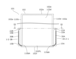
- 2 is a sectional view taken along line II-II in FIG. 1.
- FIG. 3 is a sectional view taken along line III-III in FIG. 2.
- FIG. FIG. 3 is a perspective view showing the first casing of FIG. 2;
- FIG. 3 is a top view showing the first water-absorbing mat of FIG. 2;
- FIG. 3 is a bottom view showing the first water-absorbing mat of FIG. 2;
- 2 is a front view showing the operation panel of FIG. 1.
- FIG. FIG. 3 is a cross-sectional view showing a state in which the first water-absorbing mat in FIG. 2 is in a first installation position and the second water-absorbing mat is in a second installation position.
- FIG. 9 is a sectional view taken along line IX-IX in FIG. 8, showing a state in which the first water-absorbing mat in FIG. 3 is in a first installation position and the second water-
- FIG. 1 is a side view showing an elevator 100 to which a water absorbing mat device according to the first embodiment is applied.
- FIG. 2 is a cross-sectional view taken along line II-II in FIG.
- FIG. 3 is a sectional view taken along line III-III in FIG. 2.
- the elevator 100 includes a car 101 on which passengers can ride, a water absorption mat device 1, a counterweight 103, a hoist 104, a deflection wheel 105, a main rope 106, an elevator control device (not shown), and a plurality of components. It has an operation panel 115.
- the car 101 and the counterweight 103 are connected to each other by a main rope 106.
- One end of the main rope 106 is connected to the top of the car 101.
- the other end of the main rope 106 is connected to the upper part of the counterweight 103.
- the hoist 104 has a driving sheave (not shown), and a main rope 106 is wound around the driving sheave and the deflecting sheave 105. Inside the hoistway 120, a car 101 and a counterweight 103 are suspended by a main rope 106.
- the car 101 and the counterweight 103 can move vertically inside the hoistway 120 according to the operation of the hoist 104.
- the car 101 is stopped at a stop position corresponding to the landing on the first floor, which is the lowest floor.
- the elevator control device controls the operation of the car 101 by controlling the hoisting machine 104 based on signals from each operation panel 115.
- Each operation panel 115 is installed at a landing on each floor.
- a passenger in the elevator 100 can move the car 101 to the landing floor where the passenger is waiting.
- the car 101 has a car body 102 and a car door (not shown).
- the car body 102 includes a wall 102a, a car ceiling member 102e, and a car floor member 102f.
- the wall 102a has a first side wall 110a, a second side wall 110b, a front wall 110c, and a back wall 110d.
- the first side wall 110a and the second side wall 110b are arranged to face each other.
- the front wall 110c is connected to each of the landing side ends of the first side wall 110a and the second side wall 110b.
- the back wall 110d is connected to each of the ends of the first side wall 110a and the second side wall 110b on the side opposite to the landing area.
- the front wall 110c and the back wall 110d are arranged to face each other.
- the car ceiling member 102e closes the upper part of the space surrounded by the first side wall 110a, the second side wall 110b, the front wall 110c, and the back wall 110d.
- the car floor member 102f closes the lower part of the space surrounded by the first side wall 110a, the second side wall 110b, the front wall 110c, and the back wall 110d.
- the surface of the car floor member 102f inside the car 101 is a floor surface 102FL.
- a first opening 110ah which is an opening, is formed at the lower end of the first side wall 110a.
- a second opening 110bh which is an opening, is formed at the lower end of the second side wall 110b.
- the front wall 110c is provided with an opening 110g.
- the car door can block the entrance/exit 110g.
- the elevator control device moves the car door to open the entrance/exit 110g.
- the doorway 110g is open, passengers can pass through the doorway 110g to go back and forth between the interior of the car 101 and the platform.
- the water-absorbing mat device 1 includes a water-absorbing mat mechanism 2 and an operation section 5 that drives the water-absorbing mat mechanism 2.
- the water absorption mat mechanism 2 includes a first mat unit 3A and a second mat unit 3B.
- the first mat unit 3A is arranged on the outside of the car 101 and on the side surface of the first side wall 110a.
- the first mat unit 3A includes a first housing 10A, a first moving mechanism 20A, a first water absorbing mat 30A, and a first control section 50A.
- FIG. 4 is a perspective view showing the first housing 10A of FIG. 2.
- FIG. 4 shows the first housing 10A viewed from the first side wall 110a side.
- the shape of the first housing 10A is a rectangular parallelepiped.
- the first housing 10A includes a pair of first housing vertical plate members 11A, a pair of first housing horizontal plate members 12A, a first housing side wall 13A, and a first guide plate 15A. There is.
- the pair of first housing vertical plate members 11A and the pair of first housing horizontal plate members 12A are arranged so as to protrude in the normal direction of the outer surface of the first side wall 110a.
- the pair of first casing vertical plate members 11A are arranged such that the longitudinal direction of each first casing vertical plate member 11A is along the vertical direction.
- the pair of first case horizontal plate members 12A are arranged such that the longitudinal direction of each first case horizontal plate member 12A is along the horizontal direction.
- the outer surface of the first side wall 110a When the outer surface of the first side wall 110a is viewed from the normal direction to the outer surface of the first side wall 110a, the outer surface of the first side wall 110a includes a pair of first housing vertical plate members 11A, A rectangular space is formed surrounded by the pair of first housing horizontal plate members 12A.
- the first housing side wall 13A is arranged to face the first side wall 110a.
- the first housing side wall 13A is arranged along the respective ends of the pair of first housing vertical plate members 11A and the pair of first housing horizontal plate members 12A.
- the first housing side wall 13A closes a rectangular space surrounded by the pair of first housing vertical plate members 11A and the pair of first housing horizontal plate members 12A.
- a first housing through hole 14A is provided at each of the upper end portions of the pair of first housing vertical plate members 11A.
- the first guide plate 15A is a long plate material.
- the first guide plate 15A is arranged at the lower end inside the space surrounded by the first side wall 110a and the first housing 10A.
- the first guide plate 15A is arranged such that the longitudinal direction of the first guide plate 15A is along the horizontal direction.
- first guide plate 15A One side along the longitudinal direction of the first guide plate 15A is arranged on the side of the first housing side wall 13A, and the other side along the longitudinal direction is arranged on the side of the first side wall 110a.
- the first guide plate 15A is arranged so as to be inclined downward from the first housing side wall 13A toward the first side wall 110a.
- the first guide plate 15A is curved when viewed along the longitudinal direction.
- the first guide plate 15A is arranged so that the curve of the first guide plate 15A extends from the inside of the car 101 to the outside.
- the first guide plate 15A is curved when viewed along the longitudinal direction, but the first guide plate 15A is bent at one or more places by bending to form a curved shape. may have been done.
- the first moving mechanism 20A includes a first motor 21A, a first shaft 22A connected to a rotating shaft of the first motor 21A, and a first torque sensor 23A as a first detector.
- the first moving mechanism 20A moves the first water absorbing mat 30A.
- the first motor 21A is supported on the outside of the first housing 10A.
- the first motor 21A is operated by power supplied from a power supply means (not shown). Control of the first motor 21A is performed by the first control section 50A.
- the first control unit 50A will be explained later.
- the first shaft 22A is passed through a pair of first housing through holes 14A and supported by the first housing 10A. Both ends of the first shaft 22A are rotatably supported by the pair of first housing through holes 14A.
- the first shaft 22A may be supported by each first housing through hole 14A via a bearing member.
- the rotational motion of the first motor 21A is transmitted from the rotation shaft of the first motor 21A to the first shaft 22A. Due to the rotational movement of the first motor 21A, the first shaft 22A rotates around the axis of the first shaft 22A.
- the first torque sensor 23A detects rotational torque related to the first shaft 22A.
- the rotational torque detected by the first torque sensor 23A is transmitted to the first control unit 50A through wiring (not shown).
- the first control unit 50A controls the first motor 21A based on the detection result of the first torque sensor 23A.
- the control method of the first control section 50A will be explained later.
- a transmission mechanism such as a transmission made of a member such as a gear may be further provided between the rotating shaft of the first motor 21A and the first shaft 22A.
- the first water absorbing mat 30A is a sheet-like member.
- FIG. 5 is a top view showing the first water-absorbing mat 30A of FIG. 2.
- FIG. 6 is a bottom view showing the first water-absorbing mat 30A of FIG. 2.
- the first water-absorbing mat 30A includes a first water-absorbing mat main body 31A, a first contact member 32A installed on the back surface of the first water-absorbing mat main body 31A, a first connecting portion 33A, and a plurality of first winding members. It has a first wire 34A.
- the first water-absorbing mat main body 31A includes a plurality of first water-absorbing plates 40A lined up in the moving direction of the first water-absorbing mat 30A, and a first connecting member (not shown) that connects each of the plurality of first water-absorbing plates 40A to each other. have.
- Each first water absorbing plate 40A is a long plate material. In this embodiment, eight first water absorption plates 40A are used.
- the first water absorbing plates 40A are connected to each other by a first connecting member in a direction perpendicular to the respective longitudinal directions. By bending the first connecting member between the connected adjacent first water absorbing plates 40A, the first water absorbing mat main body 31A can be bent in the direction in which the first water absorbing plates 40A are lined up.
- the first water absorption plate 40A is a plate material containing a diatomaceous earth component.
- the first water absorption plate 40A is formed by firing diatomaceous earth.
- Diatomaceous earth is a deposit made up of the remains of diatoms.
- Diatomaceous earth is a porous material whose main component is silicon dioxide hydrate.
- Diatomaceous earth component has excellent water absorption and hygroscopicity.
- the first water-absorbing plate 40A has better water absorption and hygroscopicity than a diatomaceous earth component, a water-absorbing material, or a plate material that does not contain a moisture-absorbing material.
- the coefficient of friction between the first contact member 32A and the floor surface 102FL of the car 101 is smaller than the coefficient of friction between the first water-absorbing mat body 31A and the floor surface 102FL of the car 101.
- the first contact members 32A are five steel tapes.
- the first connecting portion 33A is arranged at one end of the first water absorbing mat main body 31A.
- the first connecting portion 33A includes a first connecting portion main body 45A and a plurality of first magnets 46A that are first connecting members.
- the first connecting portion main body 45A is a plate material having the same length as the first water absorption plate 40A.
- a plurality of first magnets 46A are arranged on the side surface of the first connection portion main body 45A opposite to the side surface facing the first water absorption plate 40A.
- each first wire 34A is connected to the end of the first water-absorbing mat main body 31A opposite to the end where the first connecting portion 33A is arranged. In this embodiment, seven first wires 34A are used.
- the end where the first connecting portion 33A is installed is the tip of the first water absorbing mat 30A.
- each first wire 34A opposite to the end connected to the first water-absorbing mat main body 31A is connected to the first shaft 22A.
- the first control section 50A is supported by the first motor 21A.
- the first control section 50A controls the first motor 21A based on the signal from the operation section 5. Note that, although the first control unit 50A is supported by the first motor 21A, it is not limited to this and may be installed anywhere.
- the second mat unit 3B is arranged on the outside of the car 101 and on the side surface of the second side wall 110b.
- the second mat unit 3B differs from the first mat unit 3A only in that it is disposed on the second side wall 110b. Therefore, in the above description of the first mat unit 3A, the prefix "first” is replaced with “second”, the last symbol “A” is replaced with “B”, and “first side wall 110a” is replaced with “second”.
- the explanation replaced with "second side wall 110b" is the explanation of the second mat unit 3B.
- FIG. 7 is a front view showing the operation panel 115 of FIG. 1.
- the operation unit 5 is attached to at least one operation panel 115 among the plurality of operation panels 115.
- the operation unit 5 includes an operation button 60 and a wiring (not shown) that is a transmission member that transmits a signal from the operation button 60.
- the operation button 60 is arranged on at least one operation panel 115 among the plurality of operation panels 115.
- a contact signal from the operation button 60 is input to the first control section 50A and the second control section 50B via wiring.
- the water absorbing mat device 1 is operated by a building manager. Therefore, the operation button 60 is arranged on an operation panel 115 installed at the platform on the floor where the building manager's room is located. In this embodiment, the operation panel 115 on which the operation buttons 60 are arranged is installed on the lowest landing floor.
- first water-absorbing mat 30A and the second water-absorbing mat 30B show a state in which the first water absorbent mat 30A is in the first retracted position and the second water absorbent mat 30B is in the second retracted position. That is, the first water-absorbing mat 30A is drawn into the first housing 10A, and the second water-absorbing mat 30B is drawn into the second housing 10B.
- Each first wire 34A is wound around the first shaft 22A by the rotation of the first motor 21A and the first shaft 22A. Since each first wire 34A is wound up, the first water absorbing mat 30A is housed in the internal space of the first housing 10A. That is, the first water-absorbing mat 30A is located on the back side of the first side wall 110a of the car 101. In this state, the first water-absorbing mat 30A is in the first retracted position.
- Each second wire 34B is wound around the second shaft 22B by the rotation of the second motor 21B and the second shaft 22B. Since each second wire 34B is wound up, the second water-absorbing mat 30B is housed in the internal space of the second housing 10B. That is, the second water-absorbing mat 30B is located on the back side of the second side wall 110b of the car 101. In this state, the second water-absorbing mat 30B is in the second retracted position.
- FIG. 8 is a sectional view showing a state in which the first water-absorbing mat 30A of FIG. 2 is in the first laying position and the second water-absorbing mat 30B is in the second laying position.
- FIG. 9 is a cross-sectional view taken along line IX-IX in FIG. 8, showing a state in which the first water-absorbing mat 30A in FIG. 3 is in the first laying position and the second water-absorbing mat 30B is in the second laying position.
- each first wire 34A is unwound from the first shaft 22A.
- the first water-absorbing mat main body 31A comes out from the first housing 10A.
- the first water-absorbing mat body 31A passes through the first opening 110ah, is sent out from the first housing 10A, and covers the floor surface 102FL. That is, the first water-absorbing mat main body 31A is placed on the floor surface 102FL of the car 101. In this state, the first water absorbing mat 30A is in the first installation position.
- each second wire 34B is unwound from the second shaft 22B due to the rotation of the second motor 21B and the second shaft 22B.
- the second water absorption mat main body 31B comes out from the second housing 10B.
- the second water-absorbing mat body 31B passes through the second opening 110bh, is sent out from the second housing 10B, and covers the floor surface 102FL. That is, the second water-absorbing mat main body 31B is placed on the floor surface 102FL of the car 101. In this state, the second water-absorbing mat 30B is in the second installation position.
- the first water-absorbing mat 30A and the second water-absorbing mat 30B are lined up with each other on the floor surface 102FL of the car 101. There is. The tip of the first water-absorbing mat 30A and the tip of the second water-absorbing mat 30B are in contact with each other.
- the first water-absorbing mat 30A and the second water-absorbing mat 30B that are in contact with each other are connected to each other by the magnetic force of the first magnet 46A and the second magnet 46B. That is, the first connecting portion 33A and the second connecting portion 33B are removably connected to each other.
- a worker such as a manager of the elevator 100 determines whether or not to drive the water-absorbing mat device 1 based on environmental conditions such as rainfall conditions.
- the worker determines that it is necessary to drive the water absorption mat device 1, the worker operates the operation button 60. That is, the worker presses the operation button 60.
- the first control section 50A and the second control section 50B are able to control the information when the operation button 60 is pressed. Understand that the state is
- the first control unit 50A knows whether the first water absorbing mat 30A is in the first retracted position or the first laying position. When detecting that the operation button 60 is pressed, the first control unit 50A determines the position of the first water absorbing mat 30A.
- the first control unit 50A determines that the first water-absorbing mat 30A is in the first retracted position, the first control unit 50A rotates the first motor 21A in the sending direction.
- the rotational feeding direction of the first motor 21A is a direction in which the first water absorbing mat 30A moves from the first retracted position to the first laying position, that is, the first water absorbing mat 30A is sent out from the first housing 10A. is the direction of rotation. Note that in the rotation direction of the first shaft 22A, the feeding direction is also the rotation direction in the same direction.
- the rotational force of the first motor 21A is transmitted to the first shaft 22A.
- the first shaft 22A rotates in the delivery direction around its axis. As a result, each first wire 34A wound around the first shaft 22A is unwound.
- the first water-absorbing mat 30A moves in the direction of being pushed out from the first housing 10A.
- the first water-absorbing mat 30A has the following forces: the force of gravity acting on the first water-absorbing mat 30A itself, and the force acting in the direction of unraveling each first wire 34A and pushing out the first water-absorbing mat 30A from the first casing 10A. is working. These forces move the first water-absorbing mat 30A in a direction in which it is pushed out from the first housing 10A.
- the first contact member 32A installed on the back surface of the first water-absorbing mat 30A contacts the first guide plate 15A. Thereby, the first water-absorbing mat 30A moves smoothly along the first guide plate 15A.
- the first water-absorbing mat 30A passes through the first opening 110ah and moves on the floor surface 102FL of the car 101.
- the first contact member 32A is in contact with the floor surface 102FL of the car 101.
- the first water absorbent mat 30A when the first water absorbent mat 30A is continuously fed out from the first housing 10A, the first water absorbent mat 30A eventually reaches the first laying position.
- the first water-absorbing mat 30A When the first water-absorbing mat 30A is located at the first installation position, the first water-absorbing mat 30A is arranged to cover the floor surface 102FL of the car 101.
- the second water-absorbing mat 30B in the second retracted position is also sent out from the second housing 10B. Eventually, the second water-absorbing mat 30B passes through the second opening 110bh and reaches the second installation position.
- the first connecting part 33A and the second connecting part 33B are in contact with each other.
- the detected torque of the first torque sensor 23A and the detected torque of the second torque sensor 23B vary.
- the first control unit 50A recognizes that the first water absorbing mat 30A has reached the first installation position based on the behavior of the detected torque from the first torque sensor 23A. Thereby, the first control unit 50A stops the rotation of the first motor 21A.
- the first control unit 50A stores in a storage area (not shown) in the first control unit 50A that the first water absorbing mat 30A has reached the first laying position. This completes the movement of the first water-absorbing mat 30A to the installation position.
- the second control unit 50B recognizes that the second water-absorbing mat 30B has reached the second installation position based on the behavior of the detected torque from the second torque sensor 23B. Thereby, the second control unit 50B stops the rotation of the second motor 21B.
- the second control unit 50B stores in a storage area (not shown) in the second control unit 50B that the second water absorbing mat 30B has reached the second laying position.
- the first control unit 50A detects that the operation button 60 is pressed when the first water-absorbing mat 30A is in the first laying position, it rotates the first motor 21A in the winding direction.
- the winding direction is a rotation direction opposite to the feeding direction.
- the winding direction which is the rotating direction of the first motor 21A
- the first water absorbent mat 30A is This is the direction of rotation for moving toward the inside of the housing 10A. Note that in the rotation direction of the first shaft 22A, the winding direction is also the same rotation direction.
- the rotational force of the first motor 21A is transmitted to the first shaft 22A.
- the first shaft 22A rotates around its axis in the winding direction. Thereby, each first wire 34A is wound around the first shaft 22A.
- the first water-absorbing mat 30A moves on the floor surface 102FL of the car 101 and passes through the first opening 110ah toward the first housing 10A. move in the direction.
- the first contact member 32A installed on the back surface of the first water-absorbing mat 30A contacts the floor surface 102FL of the car 101 and the first guide plate 15A. Thereby, the first water-absorbing mat 30A moves smoothly along the floor surface 102FL of the car 101 and the first guide plate 15A.
- each first wire 34A is entirely wound around the first shaft 22A.
- the first water-absorbing mat 30A reaches the first retracted position.
- the first water absorption mat main body 31A does not cover the floor surface 102FL of the car 101, but is placed inside the first housing 10A.
- the first control unit 50A recognizes that the first water absorbing mat 30A has reached the first retracted position based on the behavior of the detected torque from the first torque sensor 23A. Thereby, the first control unit 50A stops the rotation of the first motor 21A.
- the first control unit 50A stores the fact that the first water-absorbing mat 30A has reached the first retracted position in a storage area (not shown) within the first control unit 50A. This completes the movement of the first water-absorbing mat 30A to the first retracted position.
- the second water-absorbing mat 30B when the operation button 60 is pressed, the second water-absorbing mat 30B also moves to the second housing 10B through the second opening 110bh. Eventually, the second water-absorbing mat 30B reaches the second installation position.
- the second control unit 50B recognizes that the second water-absorbing mat 30B has reached the second retracted position based on the behavior of the detected torque from the second torque sensor 23B. Thereby, the second control unit 50B stops the rotation of the second motor 21B.
- the second control unit 50B stores the fact that the second water-absorbing mat 30B has reached the second retracted position in a storage area (not shown) within the second control unit 50B. This completes the movement of the second water-absorbing mat 30B to the second retracted position.
- the water-absorbing mat device 1 includes a water-absorbing mat mechanism 2 installed in a car 101 and an operation unit 5 that drives the water-absorbing mat mechanism 2. Further, the water absorbing mat mechanism 2 includes a first mat unit 3A, and the first mat unit 3A includes a first water absorbing mat 30A and a first moving mechanism 20A that moves the first water absorbing mat 30A. ing. Further, the first water absorption mat 30A is movable between a first retracted position located on the back side of the first side wall 110a of the car 101 and a first installation position where it is laid on the floor surface 102FL of the car 101. ing.
- the first moving mechanism 20A moves the first water absorbing mat 30A between the first retracted position and the first laying position when the operating section 5 is operated.
- the first water-absorbing mat 30A has a first water-absorbing mat main body 31A including a porous material.
- the operator can lay down the first water-absorbing mat 30A on the floor surface 102FL by operating the operation unit 5 according to the rain situation. Therefore, rainwater and moisture inside the car 101 can be absorbed into the first water-absorbing mat 30A. Therefore, the humidity inside the car 101 can be maintained at an appropriate level, and the comfort inside the car 101 can be improved.
- the first water-absorbing mat 30A has excellent water-absorbing properties and quick-drying properties, it can quickly absorb moisture from the floor surface 102FL.
- the comfort inside the car 101 can be improved. Moreover, this makes it possible to reduce contamination of the floor surface 102FL with rainwater containing mud during rainfall. Furthermore, scratches and damage to the floor surface 102FL caused by umbrellas brought in by passengers of the elevator 100 can be reduced. Further, rainwater and moisture inside the basket 101 can be absorbed by the first water-absorbing mat main body 31A including a porous material. Therefore, the moisture inside the cage 101 and the ability to remove moisture can be improved. Further, the operator can retreat the first water absorbing mat 30A to the back side of the first side wall 110a of the car 101 by operating the operation unit 5 when the rain ends. Therefore, the first water-absorbing mat 30A containing the porous material can be dried outside the basket 101.
- the dried first water-absorbing mat 30A can be used again, and the moisture inside the basket 101 and the ability to remove moisture can be improved. Furthermore, this allows the worker to use mechanical power to lay down the first water-absorbing mat 30A on the floor surface 102FL when it rains. Therefore, the workload of the worker can be reduced. Moreover, the first water absorbing mat 30A can be laid down on the floor surface 102FL more quickly.
- the first water-absorbing mat main body 31A includes a plurality of first water-absorbing plates 40A that are connected to each other and lined up in the moving direction of the first water-absorbing mat 30A. Furthermore, the first water-absorbing mat main body 31A can be bent between adjacent first water-absorbing plates 40A in the direction in which the plurality of first water-absorbing plates 40A are lined up. Thereby, a plate material containing porous material at a higher density can be used. Therefore, the moisture inside the cage 101 and the ability to remove moisture can be improved.
- the porous material contained in the first water-absorbing mat body 31A is diatomaceous earth.
- diatomaceous earth with excellent water absorption and hygroscopicity can be used by the first water absorption mat main body 31A. Therefore, the moisture inside the cage 101 and the ability to remove moisture can be improved.
- the first water-absorbing mat 30A has the first contact member 32A installed on the first water-absorbing mat main body 31A. Further, when the first water absorbing mat 30A is located at the first installation position, the first contact member is in contact with the floor surface 102FL. Further, the coefficient of friction between the floor surface 102FL and the first contact member 32A is smaller than the coefficient of friction between the floor surface 102FL and the first water-absorbing mat body 31A. Thereby, the first water-absorbing mat 30A can move more smoothly on the floor surface 102FL. Therefore, a smaller motor can be used as the first motor 21A. Furthermore, damage to the floor surface 102FL due to movement of the first water-absorbing mat 30A can be reduced.
- the first opening 110ah is located at the lower end of the first side wall 110a.
- the inner surface of the first side wall 110a of the car 101 is a continuous large surface without being partitioned by the first opening 110ah. Therefore, the design of the cage 101 is improved. Furthermore, passengers in the elevator 100 are less likely to notice the first opening 110ah, and the design of the car 101 is improved.
- the first opening 110ah is located at a higher position than the floor surface 102FL. Further, the height distance from the floor surface 102FL to the lower end of the first opening 110ah is 15 cm or more.
- the first water-absorbing mat 30A covers the lower end of the inner surface of the first side wall 110a up to a height of 15 cm or more from the floor surface 102FL. Therefore, it is possible to reduce contamination of the lower end portion of the inner surface of the first side wall 110a with rainwater containing mud during rain. Furthermore, scratches and damage to the lower end portion of the inner surface of the first side wall 110a caused by umbrellas brought by passengers in the elevator 100 can be reduced.
- the first water-absorbing mat 30A has the first connecting portion 33A installed at the end of the first water-absorbing mat main body 31A. Further, when the first water absorbing mat 30A is located at the first installation position, the first connecting portion 33A is removably connected to a part of the car 101. Therefore, the positional shift of the first water-absorbing mat 30A can be reduced.
- the first connecting portion 33A includes a magnet. Therefore, the first connecting portion 33A can be manufactured using easily available members.
- the water-absorbing mat device 1 includes the second mat unit 3B, and the second mat unit 3B includes a second water-absorbing mat 30B and a second water-absorbing mat 30B. It has a second moving mechanism 20B for moving. Further, the second water-absorbing mat 30B is movable between a second retracted position located on the back side of the second side wall 110b and a second laid-down position laid on the floor surface 102FL. The second moving mechanism 20B moves the second water-absorbing mat 30B between the second retracted position and the second laying position when the operating section 5 is operated.
- the first water absorbent mat 30A is located at the first installation position and the second water absorption mat 30B is located at the second installation position
- the first water absorption mat 30A and the second water absorption mat 30B are placed on the floor. They are lined up with each other at 102FL.
- the second water-absorbing mat 30B has a second water-absorbing mat main body 31B containing a porous material.
- the operator can lay down the first water-absorbing mat 30A and the second water-absorbing mat 30B on the floor surface 102FL by operating the operation unit 5 according to the rain situation. Therefore, rainwater and moisture inside the car 101 can be absorbed into the first water-absorbing mat 30A and the second water-absorbing mat 30B.
- the humidity inside the car 101 can be maintained at an appropriate level, and the comfort inside the car 101 can be improved. Furthermore, since the first water absorbing mat 30A and the second water absorbing mat 30B have excellent water absorbing properties and quick drying properties, they can quickly absorb moisture from the floor surface 102FL. Therefore, the comfort inside the car 101 can be improved. Moreover, this makes it possible to reduce contamination of the floor surface 102FL with rainwater containing mud during rainfall. Furthermore, scratches and damage to the floor surface 102FL caused by umbrellas brought in by passengers of the elevator 100 can be reduced. Further, rainwater and moisture inside the basket 101 can be absorbed into the first water-absorbing mat main body 31A and the second water-absorbing mat main body 31B including a porous material.
- the moisture inside the cage 101 and the ability to remove moisture can be improved.
- the operator operates the operation unit 5 to retreat the first water absorbent mat 30A to the back side of the first side wall 110a of the car 101, and moves the second water absorbent mat 30B to the back side of the first side wall 110a of the car 101. It can be evacuated to the back side of the second side wall. Therefore, the first water-absorbing mat 30A and the second water-absorbing mat 30B containing the porous material can be dried outside the basket 101. Therefore, the dried first water-absorbing mat 30A can be used again, and the moisture inside the basket 101 and the ability to remove moisture can be improved.
- the first water absorbent mat 30A and the second water absorbent mat 30B can be laid down on the floor surface 102FL more quickly.
- the first mat unit 3A which includes parts such as a housing, a motor, and a shaft
- the second mat unit 3B can be downsized.
- the second water-absorbing mat main body 31B includes a plurality of second water-absorbing plates 40B that are connected to each other and lined up in the moving direction of the second water-absorbing mat 30B.
- the second water-absorbing mat main body 31B is bendable between adjacent second water-absorbing plates 40B in the direction in which the plurality of second water-absorbing plates 40B are lined up. Therefore, a plate material containing porous material at a higher density can be used. Therefore, the moisture inside the cage 101 and the ability to remove moisture can be improved.
- the porous material contained in the second water-absorbing mat main body 31B is diatomaceous earth.
- diatomaceous earth with excellent water absorption and hygroscopicity can be used by the second water absorption mat main body 31B. Therefore, the moisture inside the cage 101 and the ability to remove moisture can be improved.
- the first water-absorbing mat 30A has the first connecting portion 33A
- the second water-absorbing mat 30B has the second connecting portion 33B.
- the first connecting portion 33A and the second connecting portion 33B are removed from each other. possible to be connected. Therefore, it is possible to reduce misalignment of the first water absorbing mat 30A and the second water absorbing mat 30B.
- each of the first connecting portion 33A and the second connecting portion 33B includes a magnet. Therefore, the first connecting portion 33A and the second connecting portion 33B can be manufactured using easily available members.
- the second opening 110bh is located at the lower end of the second side wall 110b.
- the inner surface of the second side wall 110b of the car 101 is a continuous large surface without being partitioned by the second opening 110bh. Therefore, the design of the cage 101 is improved. Furthermore, passengers in the elevator 100 are less likely to notice the second opening 110bh, and the design of the car 101 is improved.
- the second opening 110bh is located at a higher position than the floor surface 102FL, and the height distance from the floor surface 102FL to the lower end of the second opening 110bh is , 15 cm or more.
- the second water-absorbing mat main body 31B covers the lower end of the inner surface of the second side wall 110b up to a height of 15 cm or more from the floor surface 102FL. Therefore, it is possible to reduce contamination of the lower end portion of the inner surface of the second side wall 110b by rainwater containing mud during rain. Furthermore, scratches and damage to the lower end portion of the inner surface of the second side wall 110b caused by umbrellas brought in by passengers of the elevator 100 can be reduced.
- the operation unit 5 has one operation button 60, and the water-absorbing mat device 1 is driven when the operation button 60 is operated. Thereby, the operator can easily drive the water absorption mat device 1 by operating one operation button 60.
- the operation unit 5 is attached to an operation panel installed at an elevator landing. This allows the operator to easily operate the operation button 60.
- first water absorbing plate 40A and the second water absorbing plate 40B of Embodiment 1 contain a diatomaceous earth component. However, it is not limited to this.
- the first water absorbing plate 40A and the second water absorbing plate 40B may include a material with excellent water absorbing properties. For example, a porous material may be used as the material with excellent water absorption.
- first water-absorbing mat main body 31A of the first embodiment has eight first water-absorbing plates 40A
- second water-absorbing mat main body 31B has eight second water-absorbing plates 40B.
- Flexible sheet materials may be used as the first water-absorbing mat body 31A and the second water-absorbing mat body 31B.
- a sheet material may be used in which a porous material, preferably a material containing a diatomaceous earth component, is adhered to or contained in the base material of the sheet material. good.
- a porous material preferably a material containing a diatomaceous earth component
- first connecting member and the second connecting member of Embodiment 1 are well-known members that can connect a plurality of plate materials.
- members such as an adhesive tape, a hook-and-loop fastener, and a hinge may be used as the first connecting member.
- a bag-like member may be used as the first connecting member. Inside the bag-like member, compartments are formed as many as the number of first water absorbing plates 40A, and one compartment can accommodate the first water absorbing plates 40A. By inserting the first water absorbing plates 40A into each section, the first water absorbing plates 40A are connected so as to be lined up in a direction perpendicular to the longitudinal direction of each of the first water absorbing plates 40A.
- first contact member 32A may also be used as the first connection member.
- Each of the first water absorbing plates 40A may be connected to each other by pasting each first contact member 32A across each of the first water absorbing plates 40A.
- each of the first water absorbing plates 40A may be connected by arranging any one of the plurality of first wires 34A across each of the first water absorbing plates 40A.
- the second connecting member can also have the same configuration as the first connecting member.
- the first contact member 32A of the first embodiment is five steel tapes. However, it is not limited to this. For example, four or less steel tapes, or six or more steel tapes may be used.
- the first contact member 32A may be a member made of a resin such as fluororesin exposed to the floor surface 102FL of the car 101.
- a plurality of rollers may be used as the first contact member 32A.
- the first water-absorbing mat 30A can move more smoothly on the floor surface 102FL. Therefore, a smaller motor can be used as the first motor 21A. Furthermore, damage to the floor surface 102FL due to movement of the first water-absorbing mat 30A can be reduced.
- the water absorbing mat device 1 of the first embodiment includes a first mat unit 3A and a second mat unit 3B.
- the water absorbing mat device 1 may include only one of the first mat unit 3A and the second mat unit 3B.
- the water absorbing mat device 1 may include only the first mat unit 3A.
- the first connecting portion 33A may be in contact with the second side wall 110b. That is, the first connecting portion 33A may be removably connected to the inside of the second side wall 110b by magnetic force.
- the water-absorbing mat device 1 may include only the first mat unit 3A disposed outside the back wall 110d. In this case, the first opening 110ah is formed in the back wall 110d.
- first magnets 46A are arranged in the first connection part 33A of the first embodiment, and a plurality of second magnets 46B are arranged in the second connection part 33B.
- a mechanical connecting member such as a hook and loop fastener, a hook, or a button may be used for the first connecting portion 33A and the second connecting portion 33B.
- first connecting portion 33A and the second connecting portion 33B of the first embodiment are connected to each other.
- the first connecting portion 33A and the second connecting portion 33B may be connected to any part inside the car 101.
- it may be connected to the floor surface 102FL or a part of the rear wall 110d.
- the first torque sensor 23A is used as the first detector in the first embodiment, and the second torque sensor 23B is used as the second detector.
- a limit switch or a photosensor may be used as the first detector and the second detector.
- the positions of the first water-absorbing mat 30A and the second water-absorbing mat 30B can also be detected using a limit switch or a photosensor.
- encoders that detect the respective rotation amounts of the first shaft 22A and the second shaft 22B may be arranged as the first detector and the second detector.
- the respective positions of the first water-absorbing mat 30A and the second water-absorbing mat 30B may be grasped by calculating the moving distances of the first water-absorbing mat 30A and the second water-absorbing mat 30B based on the output of each encoder.
- the first control section 50A and the second control section 50B of the first embodiment each perform control independently based on the state in which the operation button 60 is pressed.
- the first control unit 50A and the second control unit 50B may perform control after mutually recognizing each other's operating status and storage area information. For example, when the operation button 60 is pressed, if the positions of the first water absorption mat 30A and the second water absorption mat 30B are different from each other, the first control section 50A and the second control section 50B control the first motor 21A. Also, the second motor 21B may not be operated. Thereby, the water absorption mat device 1 can be driven more safely.
- first control unit 50A and the second control unit 50B of the first embodiment store the position of the first water absorption mat 30A or the second water absorption mat 30B in a storage area (not shown).
- a limit switch or a photosensor may be arranged to detect the positions of the first water-absorbing mat 30A and the second water-absorbing mat 30B.
- the operating status of the water absorbing mat device 1 may be displayed on the operation button 60 of the first embodiment.
- a lighting device may be disposed inside the operation button 60, and the operating status of the water absorbing mat device 1 may be displayed based on the lighting state of the lighting device.
- a light may be turned on inside the operation button 60.
- the interior of the operation button 60 may be illuminated on and off.
- the water absorbing mat device 1 of the first embodiment has an operation button 60 exposed on the surface of the operation panel 115.
- the operation button 60 may be arranged in a space closed by a lid within the wall of the landing, or in a space closed by a lid inside the car 101. Further, for example, the operation button 60 may be placed in the management room of the building. Alternatively, the operation button 60 may be arranged inside the control panel of the elevator 100.
- the water absorbing mat device 1 of the first embodiment has an operation button 60.
- a drive signal may be transmitted to the water-absorbing mat device 1 by pressing buttons that are standardly equipped on the operation panel 115 in a preset order. Thereby, there is no need to specially install the operation button 60 on the operation panel 115.
- the water absorbing mat device 1 of the first embodiment has one operation button 60.
- it is not limited to this.
- it may have two operation buttons corresponding to each of the first mat unit 3A and the second mat unit 3B.
- the first opening 110ah in the first embodiment is formed at the lower end of the first side wall 110a
- the second opening 110bh is formed at the lower end of the second side wall 110b.
- the first opening 110ah and the second opening 110bh may be formed above the lower ends of the corresponding first side wall 110a and second side wall 110b.
- the first opening 110ah and the second opening 110bh may be located at a position higher than the floor surface 102FL of the car 101.
- the distance in the height direction from the floor surface 102FL of the car 101 to the lower ends of the first opening 110ah and the second opening 110b may be 15 cm or more.
- the elevator 100 of the first embodiment is operated with the first water-absorbing mat 30A in the first installation position and the second water-absorbing mat 30B in the second installation position.
- the stopping position corresponding to each floor of the car 101 may be changed.
- the thickness of the first water-absorbing mat 30A is smaller than the standard stopping position of the car 101.
- the stop position of the car 101 may be set to a position lower by that amount.
- the standard stopping position of the car 101 is the stopping position of the car 101 when the first water-absorbing mat 30A is at the first retracted position and the second water-absorbing mat 30B is at the second retracted position.
- 1 Water absorption mat device 2 Water absorption mat mechanism, 3A First mat unit, 3B Second mat unit, 5 Operation section, 10A First housing, 10B Second housing, 11A First housing vertical plate member, 12A First Housing horizontal plate member, 13A first housing side wall, 14A first housing through hole, 15A first guide plate, 15B second guide plate, 20A first moving mechanism, 20B second moving mechanism, 21A first motor, 21B second motor, 22A first shaft, 22B second shaft, 23A first torque sensor (first detector), 23B second torque sensor (second detector), 30A first water absorption mat, 30B second water absorption mat , 31A first water absorption mat body, 31B second water absorption mat body, 32A first contact member, 33A first connection part, 33B second connection part, 34A first wire (first winding member), 34B second wire ( 2nd winding member), 40A first water absorption plate, 40B second water absorption plate, 45A first connection body, 46A first magnet, 46B second magnet, 50A first control section, 50B second control section, 60 operation Buttons
Landscapes
- Engineering & Computer Science (AREA)
- Civil Engineering (AREA)
- Mechanical Engineering (AREA)
- Structural Engineering (AREA)
- Passenger Equipment (AREA)
Abstract
This water-absorbing mat device for an elevator comprises a water-absorbing mat mechanism that is set in a car and an operation unit for driving the water-absorbing mat mechanism. The water-absorbing mat mechanism has a first mat unit. The first mat unit has a first water-absorbing mat and a first moving mechanism for moving the first water-absorbing mat. The first water-absorbing mat is movable between a first retraction position behind the wall of the car and a first laying position on the floor surface through a first opening formed in the wall. The first moving mechanism moves the first water-absorbing mat between the first retraction position and the first laying position when the operation unit is operated. The first water-absorbing mat has a first water-absorbing mat body containing a porous material.
Description
本開示は、エレベーターの吸水マット装置に関するものである。
The present disclosure relates to a water absorbing mat device for an elevator.
従来、スチールテープを巻き取ることで塵埃、又は雨水が付着した敷物をかご室の壁の裏に引き込み、清掃後、かご室の床を覆う位置に敷物を戻すエレベーターのかご装置が知られている(例えば特許文献1参照)。
Conventionally, an elevator car device is known in which a rug with dust or rainwater is pulled behind the wall of the car by winding a steel tape, and after cleaning, the rug is returned to a position covering the floor of the car. (For example, see Patent Document 1).
従来のかご装置の敷物では、かご内の水分、及び湿気を除去する能力が足りないという問題があった。
Conventional carpets for car devices have a problem in that they lack the ability to remove water and moisture from inside the car.
本開示は、上記のような問題を解決するためになされたものであり、かご内の水分、及び湿気を除去する能力を向上させるエレベーターの吸水マット装置を提供することを目的とする。
The present disclosure has been made in order to solve the above-mentioned problems, and aims to provide a water-absorbing mat device for an elevator that improves the ability to remove water and humidity inside a car.
本開示に係るエレベーターの吸水マット装置は、かごに設置される吸水マット機構と、 吸水マット機構を駆動させる操作部と、を備え、吸水マット機構は、第1マットユニットを有しており、第1マットユニットは、第1吸水マットと、第1吸水マットを移動させる第1移動機構とを有しており、第1吸水マットは、かごの壁の裏側に位置する第1退避位置と、かごの床面に敷設される第1敷設位置との間で、壁に設けられた第1開口部を通って移動可能になっており、第1移動機構は、操作部が操作されることによって第1吸水マットを第1退避位置と第1敷設位置との間で移動させ、第1吸水マットは、多孔質材を含む第1吸水マット本体を有している。
A water-absorbing mat device for an elevator according to the present disclosure includes a water-absorbing mat mechanism installed in a car, and an operation unit that drives the water-absorbing mat mechanism, and the water-absorbing mat mechanism has a first mat unit and a first mat unit. The first mat unit includes a first water-absorbing mat and a first moving mechanism that moves the first water-absorbing mat, and the first water-absorbing mat has a first retracted position located on the back side of the wall of the car, and a first retracted position located on the back side of the wall of the car. The first moving mechanism is movable through a first opening provided in the wall between the first laying position laid on the floor surface of the A first water-absorbing mat is moved between a first retracted position and a first laying position, and the first water-absorbing mat has a first water-absorbing mat body including a porous material.
本開示に係るエレベーターの吸水マット装置によれば、かご内の水分、及び湿気を除去する能力を向上させることができる。
According to the water-absorbing mat device for an elevator according to the present disclosure, it is possible to improve the ability to remove moisture and humidity inside the car.
以下、本開示の実施の形態について図面を参照して説明する。
実施の形態1.
図1は、実施の形態1による吸水マット装置が適用されるエレベーター100を示す側面図である。図2は、図1のII-II線に沿った断面図である。図3は、図2のIII-III線に沿った断面図である。 Embodiments of the present disclosure will be described below with reference to the drawings.
Embodiment 1.
FIG. 1 is a side view showing anelevator 100 to which a water absorbing mat device according to the first embodiment is applied. FIG. 2 is a cross-sectional view taken along line II-II in FIG. FIG. 3 is a sectional view taken along line III-III in FIG. 2.
実施の形態1.
図1は、実施の形態1による吸水マット装置が適用されるエレベーター100を示す側面図である。図2は、図1のII-II線に沿った断面図である。図3は、図2のIII-III線に沿った断面図である。 Embodiments of the present disclosure will be described below with reference to the drawings.
FIG. 1 is a side view showing an
エレベーター100は、乗客が乗ることができるかご101と、吸水マット装置1と、釣り合い錘103と、巻上機104と、そらせ車105と、主ロープ106と、図示しないエレベーター制御装置と、複数の操作パネル115と、を有している。
The elevator 100 includes a car 101 on which passengers can ride, a water absorption mat device 1, a counterweight 103, a hoist 104, a deflection wheel 105, a main rope 106, an elevator control device (not shown), and a plurality of components. It has an operation panel 115.
かご101と釣り合い錘103とは、互いに主ロープ106で繋がれている。主ロープ106の一端部は、かご101の上部に接続されている。主ロープ106の他端部は、釣り合い錘103の上部に接続されている。
The car 101 and the counterweight 103 are connected to each other by a main rope 106. One end of the main rope 106 is connected to the top of the car 101. The other end of the main rope 106 is connected to the upper part of the counterweight 103.
巻上機104は、図示しない駆動綱車を有しており、駆動綱車及びそらせ車105には、主ロープ106が巻き掛けられている。昇降路120内には、かご101及び釣り合い錘103が主ロープ106によって吊り下げられている。
The hoist 104 has a driving sheave (not shown), and a main rope 106 is wound around the driving sheave and the deflecting sheave 105. Inside the hoistway 120, a car 101 and a counterweight 103 are suspended by a main rope 106.
かご101及び釣り合い錘103は、巻上機104の動作に応じて、昇降路120の内部を鉛直方向に移動することができる。図1では、かご101は、最下階である1階の乗り場に対応する停止位置に停止している。
The car 101 and the counterweight 103 can move vertically inside the hoistway 120 according to the operation of the hoist 104. In FIG. 1, the car 101 is stopped at a stop position corresponding to the landing on the first floor, which is the lowest floor.
エレベーター制御装置は、各操作パネル115からの信号に基づいて、巻上機104を制御することで、かご101の運行を制御する。各操作パネル115は、各階の乗り場に設置されている。
The elevator control device controls the operation of the car 101 by controlling the hoisting machine 104 based on signals from each operation panel 115. Each operation panel 115 is installed at a landing on each floor.
エレベーター100の乗客は、操作パネル115を操作することで、乗客の待つ乗り場階までかご101を移動させることができる。
By operating the operation panel 115, a passenger in the elevator 100 can move the car 101 to the landing floor where the passenger is waiting.
かご101は、かご本体102と、図示しないかご扉とを有している。かご本体102は、壁102aと、かご天井部材102eと、かご床面部材102fと、を有している。
The car 101 has a car body 102 and a car door (not shown). The car body 102 includes a wall 102a, a car ceiling member 102e, and a car floor member 102f.
壁102aは、第1側壁110a、第2側壁110b、前面壁110c、及び背面壁110dを有している。第1側壁110aと第2側壁110bとは互いに対向して配置されている。前面壁110cは、第1側壁110aと第2側壁110bとの乗り場側の端部のそれぞれに接続されて配置されている。
The wall 102a has a first side wall 110a, a second side wall 110b, a front wall 110c, and a back wall 110d. The first side wall 110a and the second side wall 110b are arranged to face each other. The front wall 110c is connected to each of the landing side ends of the first side wall 110a and the second side wall 110b.
背面壁110dは、第1側壁110aと第2側壁110bとの乗り場とは反対側の端部のそれぞれに接続されて配置されている。前面壁110cと背面壁110dとは、互いに対向して配置されている。
The back wall 110d is connected to each of the ends of the first side wall 110a and the second side wall 110b on the side opposite to the landing area. The front wall 110c and the back wall 110d are arranged to face each other.
かご天井部材102eは、第1側壁110a、第2側壁110b、前面壁110c、及び背面壁110dで囲まれた空間の上部を塞いでいる。かご床面部材102fは、第1側壁110a、第2側壁110b、前面壁110c、及び背面壁110dで囲まれた空間の下部を塞いでいる。かご101の内側のかご床面部材102fの表面は、床面102FLである。
The car ceiling member 102e closes the upper part of the space surrounded by the first side wall 110a, the second side wall 110b, the front wall 110c, and the back wall 110d. The car floor member 102f closes the lower part of the space surrounded by the first side wall 110a, the second side wall 110b, the front wall 110c, and the back wall 110d. The surface of the car floor member 102f inside the car 101 is a floor surface 102FL.
第1側壁110aの下端には、開口である第1開口部110ahが形成されている。第2側壁110bの下端には、開口である第2開口部110bhが形成されている。
A first opening 110ah, which is an opening, is formed at the lower end of the first side wall 110a. A second opening 110bh, which is an opening, is formed at the lower end of the second side wall 110b.
前面壁110cには、開口である出入り口110gが設けられている。かご扉は、出入り口110gを塞ぐことができる。
The front wall 110c is provided with an opening 110g. The car door can block the entrance/exit 110g.
かご101が目的の乗り場に対応する停止位置に停止すると、エレベーター制御装置は、かご扉を移動させて出入り口110gを開放する。出入り口110gが開放された状態では、乗客は、出入り口110gを通って、かご101の内部と乗り場とを往来することができる。
When the car 101 stops at the stop position corresponding to the target landing, the elevator control device moves the car door to open the entrance/exit 110g. When the doorway 110g is open, passengers can pass through the doorway 110g to go back and forth between the interior of the car 101 and the platform.
吸水マット装置1は、吸水マット機構2と、吸水マット機構2を駆動させる操作部5と、を備えている。吸水マット機構2は、第1マットユニット3Aと、第2マットユニット3Bと、を有している。
The water-absorbing mat device 1 includes a water-absorbing mat mechanism 2 and an operation section 5 that drives the water-absorbing mat mechanism 2. The water absorption mat mechanism 2 includes a first mat unit 3A and a second mat unit 3B.
第1マットユニット3Aは、かご101の外側であって第1側壁110aの側面に配置されている。第1マットユニット3Aは、第1筐体10Aと、第1移動機構20Aと、第1吸水マット30Aと、第1制御部50Aと、を備えている。
The first mat unit 3A is arranged on the outside of the car 101 and on the side surface of the first side wall 110a. The first mat unit 3A includes a first housing 10A, a first moving mechanism 20A, a first water absorbing mat 30A, and a first control section 50A.
図4は、図2の第1筐体10Aを示す斜視図である。図4は、第1筐体10Aを、第1側壁110a側から見た状態を示している。第1筐体10Aの形状は、直方体の形状である。
FIG. 4 is a perspective view showing the first housing 10A of FIG. 2. FIG. 4 shows the first housing 10A viewed from the first side wall 110a side. The shape of the first housing 10A is a rectangular parallelepiped.
第1筐体10Aは、一対の第1筐体縦板部材11Aと、一対の第1筐体横板部材12Aと、第1筐体側壁13Aと、第1案内板15Aと、を有している。
The first housing 10A includes a pair of first housing vertical plate members 11A, a pair of first housing horizontal plate members 12A, a first housing side wall 13A, and a first guide plate 15A. There is.
図2から図4に基づいて説明を続ける。一対の第1筐体縦板部材11Aと、一対の第1筐体横板部材12Aとは、第1側壁110aの外側の面の法線方向に突出するように配置されている。
The explanation will be continued based on FIGS. 2 to 4. The pair of first housing vertical plate members 11A and the pair of first housing horizontal plate members 12A are arranged so as to protrude in the normal direction of the outer surface of the first side wall 110a.
一対の第1筐体縦板部材11Aは、各第1筐体縦板部材11Aの長手方向が鉛直方向に沿って配置されている。一対の第1筐体横板部材12Aは、各第1筐体横板部材12Aの長手方向が水平方向に沿って配置されている。
The pair of first casing vertical plate members 11A are arranged such that the longitudinal direction of each first casing vertical plate member 11A is along the vertical direction. The pair of first case horizontal plate members 12A are arranged such that the longitudinal direction of each first case horizontal plate member 12A is along the horizontal direction.
第1側壁110aの外側の面を第1側壁110aの外側の面における法線方向から見たときに、第1側壁110aの外側の面には、一対の第1筐体縦板部材11Aと、一対の第1筐体横板部材12Aとで囲まれた方形の空間が形成されている。
When the outer surface of the first side wall 110a is viewed from the normal direction to the outer surface of the first side wall 110a, the outer surface of the first side wall 110a includes a pair of first housing vertical plate members 11A, A rectangular space is formed surrounded by the pair of first housing horizontal plate members 12A.
第1筐体側壁13Aは、第1側壁110aに対向して配置されている。第1筐体側壁13Aは、一対の第1筐体縦板部材11Aと一対の第1筐体横板部材12Aとのそれぞれの端部に沿って配置されている。第1筐体側壁13Aは、一対の第1筐体縦板部材11Aと一対の第1筐体横板部材12Aとで囲まれた方形の空間を塞いでいる。
The first housing side wall 13A is arranged to face the first side wall 110a. The first housing side wall 13A is arranged along the respective ends of the pair of first housing vertical plate members 11A and the pair of first housing horizontal plate members 12A. The first housing side wall 13A closes a rectangular space surrounded by the pair of first housing vertical plate members 11A and the pair of first housing horizontal plate members 12A.
一対の第1筐体縦板部材11Aの上端部のそれぞれには、第1筐体貫通孔14Aが設けられている。
A first housing through hole 14A is provided at each of the upper end portions of the pair of first housing vertical plate members 11A.
第1案内板15Aは、長尺の板材である。第1案内板15Aは、第1側壁110aと第1筐体10Aとで囲まれた空間の内部の下端部に配置されている。第1案内板15Aは、第1案内板15Aの長手方向が水平方向に沿うように配置されている。
The first guide plate 15A is a long plate material. The first guide plate 15A is arranged at the lower end inside the space surrounded by the first side wall 110a and the first housing 10A. The first guide plate 15A is arranged such that the longitudinal direction of the first guide plate 15A is along the horizontal direction.
第1案内板15Aの長手方向に沿った一方の辺は、第1筐体側壁13A側に配置され、長手方向に沿った他方の辺は、第1側壁110a側に配置されている。第1案内板15Aは、第1筐体側壁13Aから第1側壁110aに向かうに従って下方向に傾斜するように配置されている。
One side along the longitudinal direction of the first guide plate 15A is arranged on the side of the first housing side wall 13A, and the other side along the longitudinal direction is arranged on the side of the first side wall 110a. The first guide plate 15A is arranged so as to be inclined downward from the first housing side wall 13A toward the first side wall 110a.
第1案内板15Aは、長手方向に沿って見たときに、湾曲している。第1案内板15Aは、第1案内板15Aの湾曲がかご101の内側から外側に向かう方向に張り出すように配置されている。なお、本実施の形態では、第1案内板15Aは、長手方向に沿ってみたときに、湾曲しているが、第1案内板15Aが曲げ加工によって1箇所以上曲げられることで湾曲状に形成されていてもよい。
The first guide plate 15A is curved when viewed along the longitudinal direction. The first guide plate 15A is arranged so that the curve of the first guide plate 15A extends from the inside of the car 101 to the outside. In addition, in this embodiment, the first guide plate 15A is curved when viewed along the longitudinal direction, but the first guide plate 15A is bent at one or more places by bending to form a curved shape. may have been done.
図1から図3に戻り説明を続ける。第1移動機構20Aは、第1モータ21Aと、第1モータ21Aの回転軸に連結された第1シャフト22Aと、第1検出器としての第1トルクセンサ23Aと、を有している。第1移動機構20Aは、第1吸水マット30Aを移動させる。
Returning from FIG. 1 to FIG. 3, the explanation will be continued. The first moving mechanism 20A includes a first motor 21A, a first shaft 22A connected to a rotating shaft of the first motor 21A, and a first torque sensor 23A as a first detector. The first moving mechanism 20A moves the first water absorbing mat 30A.
第1モータ21Aは、第1筐体10Aの外側に支持されている。第1モータ21Aは、図示しない電力供給手段から供給された電力により稼働する。第1モータ21Aの制御は、第1制御部50Aによって実施される。第1制御部50Aについては、後に説明をする。
The first motor 21A is supported on the outside of the first housing 10A. The first motor 21A is operated by power supplied from a power supply means (not shown). Control of the first motor 21A is performed by the first control section 50A. The first control unit 50A will be explained later.
第1シャフト22Aは、一対の第1筐体貫通孔14Aに通されて第1筐体10Aに支持されている。第1シャフト22Aの両端のそれぞれは、一対の第1筐体貫通孔14Aに回転可能に支持されている。第1シャフト22Aは、軸受部材を介して各第1筐体貫通孔14Aに支持されていてもよい。
The first shaft 22A is passed through a pair of first housing through holes 14A and supported by the first housing 10A. Both ends of the first shaft 22A are rotatably supported by the pair of first housing through holes 14A. The first shaft 22A may be supported by each first housing through hole 14A via a bearing member.
第1モータ21Aの回転運動は、第1モータ21Aの回転軸から第1シャフト22Aへ伝達される。第1モータ21Aの回転運動により、第1シャフト22Aは、第1シャフト22Aの軸心を中心に回転する。
The rotational motion of the first motor 21A is transmitted from the rotation shaft of the first motor 21A to the first shaft 22A. Due to the rotational movement of the first motor 21A, the first shaft 22A rotates around the axis of the first shaft 22A.
第1トルクセンサ23Aは、第1シャフト22Aに係る回転トルクを検出している。第1トルクセンサ23Aが検出した回転トルクは、図示しない配線により第1制御部50Aに伝達される。第1制御部50Aは、第1トルクセンサ23Aの検出結果に基づき第1モータ21Aを制御する。第1制御部50Aの制御方法については、後に説明をする。
The first torque sensor 23A detects rotational torque related to the first shaft 22A. The rotational torque detected by the first torque sensor 23A is transmitted to the first control unit 50A through wiring (not shown). The first control unit 50A controls the first motor 21A based on the detection result of the first torque sensor 23A. The control method of the first control section 50A will be explained later.
なお、第1モータ21Aの回転軸と第1シャフト22Aとの間に、更に歯車といった部材から構成される変速器といった伝達機構を介してもよい。
Note that a transmission mechanism such as a transmission made of a member such as a gear may be further provided between the rotating shaft of the first motor 21A and the first shaft 22A.
第1吸水マット30Aは、シート状の部材である。図5は、図2の第1吸水マット30Aを示す上面図である。図6は、図2の第1吸水マット30Aを示す下面図である。
The first water absorbing mat 30A is a sheet-like member. FIG. 5 is a top view showing the first water-absorbing mat 30A of FIG. 2. FIG. 6 is a bottom view showing the first water-absorbing mat 30A of FIG. 2.
第1吸水マット30Aは、第1吸水マット本体31Aと、第1吸水マット本体31Aの裏面に設置された第1接触部材32Aと、第1接続部33Aと、第1巻き取り部材である複数の第1ワイヤ34Aと、を有している。
The first water-absorbing mat 30A includes a first water-absorbing mat main body 31A, a first contact member 32A installed on the back surface of the first water-absorbing mat main body 31A, a first connecting portion 33A, and a plurality of first winding members. It has a first wire 34A.
第1吸水マット本体31Aは、第1吸水マット30Aの移動方向へ並んでいる複数の第1吸水板40Aと、複数の第1吸水板40Aのそれぞれを互いに連結する図示しない第1連結部材と、を有している。各第1吸水板40Aは、長尺の板材である。本実施の形態では、8枚の第1吸水板40Aを使用している。
The first water-absorbing mat main body 31A includes a plurality of first water-absorbing plates 40A lined up in the moving direction of the first water-absorbing mat 30A, and a first connecting member (not shown) that connects each of the plurality of first water-absorbing plates 40A to each other. have. Each first water absorbing plate 40A is a long plate material. In this embodiment, eight first water absorption plates 40A are used.
各第1吸水板40Aは、それぞれの長手方向と直行する方向に互いに第1連結部材によって連結されている。連結されている隣り合う第1吸水板40A同士の間で第1連結部材が曲がることで、第1吸水マット本体31Aは、各第1吸水板40Aが並ぶ方向において曲げ可能になっている。
The first water absorbing plates 40A are connected to each other by a first connecting member in a direction perpendicular to the respective longitudinal directions. By bending the first connecting member between the connected adjacent first water absorbing plates 40A, the first water absorbing mat main body 31A can be bent in the direction in which the first water absorbing plates 40A are lined up.
第1吸水板40Aとは、珪藻土成分を含んだ板材である。例えば、第1吸水板40Aは、珪藻土を焼成して形成したものである。珪藻土とは、珪藻の遺骸からなる堆積物である。珪藻土とは、主成分が二酸化ケイ素水化物であり、多孔質材である。
The first water absorption plate 40A is a plate material containing a diatomaceous earth component. For example, the first water absorption plate 40A is formed by firing diatomaceous earth. Diatomaceous earth is a deposit made up of the remains of diatoms. Diatomaceous earth is a porous material whose main component is silicon dioxide hydrate.
珪藻土成分は、吸水性、及び吸湿性に優れている。第1吸水板40Aは、珪藻土成分、吸水材料、又は吸湿材料を含まない板材よりも吸水性、及び吸湿性に優れている。
Diatomaceous earth component has excellent water absorption and hygroscopicity. The first water-absorbing plate 40A has better water absorption and hygroscopicity than a diatomaceous earth component, a water-absorbing material, or a plate material that does not contain a moisture-absorbing material.
第1接触部材32Aとかご101の床面102FLとの間の摩擦係数が、第1吸水マット本体31Aとかご101の床面102FLとの間の摩擦係数よりも小さい。本実施の形態では、第1接触部材32Aは、5本のスチールテープである。
The coefficient of friction between the first contact member 32A and the floor surface 102FL of the car 101 is smaller than the coefficient of friction between the first water-absorbing mat body 31A and the floor surface 102FL of the car 101. In this embodiment, the first contact members 32A are five steel tapes.
第1接続部33Aは、第1吸水マット本体31Aの一方の端部に配置されている。第1接続部33Aは、第1接続部本体45Aと、第1接続部材である複数の第1磁石46Aと、を有している。
The first connecting portion 33A is arranged at one end of the first water absorbing mat main body 31A. The first connecting portion 33A includes a first connecting portion main body 45A and a plurality of first magnets 46A that are first connecting members.
第1接続部本体45Aは、第1吸水板40Aと等しい長さを有した板材である。第1吸水板40Aに対向する側面と反対側の第1接続部本体45Aの側面には、複数の第1磁石46Aが配置されている。
The first connecting portion main body 45A is a plate material having the same length as the first water absorption plate 40A. A plurality of first magnets 46A are arranged on the side surface of the first connection portion main body 45A opposite to the side surface facing the first water absorption plate 40A.
各第1ワイヤ34Aの一方の端部は、第1接続部33Aが配置された端部とは反対側の第1吸水マット本体31Aの端部に接続されている。本実施の形態では、7本の第1ワイヤ34Aを用いている。
One end of each first wire 34A is connected to the end of the first water-absorbing mat main body 31A opposite to the end where the first connecting portion 33A is arranged. In this embodiment, seven first wires 34A are used.
第1接続部33Aが設置された端部は、第1吸水マット30Aの先端部とする。
The end where the first connecting portion 33A is installed is the tip of the first water absorbing mat 30A.
図1から図3に戻り説明を続ける。第1吸水マット本体31Aと接続された端部とは反対側の各第1ワイヤ34Aの端部は、第1シャフト22Aに接続されている。
Returning from FIG. 1 to FIG. 3, the explanation will be continued. The end of each first wire 34A opposite to the end connected to the first water-absorbing mat main body 31A is connected to the first shaft 22A.
第1制御部50Aは、第1モータ21Aに支持されている。第1制御部50Aは、操作部5からの信号に基づいて、第1モータ21Aを制御する。なお、第1制御部50Aは、第1モータ21Aに支持されているが、これに限られたものではなく、どこに設置されていてもよい。
The first control section 50A is supported by the first motor 21A. The first control section 50A controls the first motor 21A based on the signal from the operation section 5. Note that, although the first control unit 50A is supported by the first motor 21A, it is not limited to this and may be installed anywhere.
第2マットユニット3Bは、かご101の外側であって第2側壁110bの側面に配置されている。第2マットユニット3Bは、第1マットユニット3Aの構成と比べて、第2側壁110bに配置されている点でのみ異なる。従って、前述の第1マットユニット3Aの説明において、接頭語である「第1」を「第2」に、符号最後尾の「A」を「B」に、及び「第1側壁110a」を「第2側壁110b」に置き換えた説明を、第2マットユニット3Bの説明とする。
The second mat unit 3B is arranged on the outside of the car 101 and on the side surface of the second side wall 110b. The second mat unit 3B differs from the first mat unit 3A only in that it is disposed on the second side wall 110b. Therefore, in the above description of the first mat unit 3A, the prefix "first" is replaced with "second", the last symbol "A" is replaced with "B", and "first side wall 110a" is replaced with "second". The explanation replaced with "second side wall 110b" is the explanation of the second mat unit 3B.
図7は、図1の操作パネル115を示す正面図である。操作部5は、複数の操作パネル115の内少なくとも1つの操作パネル115に取り付けられている。操作部5は、操作ボタン60と、操作ボタン60の信号を伝達する伝達部材である図示しない配線を有している。
FIG. 7 is a front view showing the operation panel 115 of FIG. 1. The operation unit 5 is attached to at least one operation panel 115 among the plurality of operation panels 115. The operation unit 5 includes an operation button 60 and a wiring (not shown) that is a transmission member that transmits a signal from the operation button 60.
操作ボタン60は、複数の操作パネル115の内少なくとも1つの操作パネル115に配置されている。操作ボタン60の接点信号は、配線を介して第1制御部50A、及び第2制御部50Bに入力される。
The operation button 60 is arranged on at least one operation panel 115 among the plurality of operation panels 115. A contact signal from the operation button 60 is input to the first control section 50A and the second control section 50B via wiring.
吸水マット装置1は、ビルの管理者によって操作される。従って、操作ボタン60は、ビルの管理者の居室が設置されている階の乗り場に設置してある操作パネル115に配置されている。本実施の形態では、操作ボタン60が配置された操作パネル115は、最下階の乗り場フロアに設置されている。
The water absorbing mat device 1 is operated by a building manager. Therefore, the operation button 60 is arranged on an operation panel 115 installed at the platform on the floor where the building manager's room is located. In this embodiment, the operation panel 115 on which the operation buttons 60 are arranged is installed on the lowest landing floor.
次に、第1吸水マット30A及び第2吸水マット30Bの状態について説明をする。図2及び図3は、第1吸水マット30Aが第1退避位置にあり、第2吸水マット30Bが第2退避位置にある状態を示している。即ち、第1吸水マット30Aが第1筐体10Aの内部に引き込まれており、第2吸水マット30Bが第2筐体10Bの内部に引き込まれている状態を示している。
Next, the states of the first water-absorbing mat 30A and the second water-absorbing mat 30B will be explained. 2 and 3 show a state in which the first water absorbent mat 30A is in the first retracted position and the second water absorbent mat 30B is in the second retracted position. That is, the first water-absorbing mat 30A is drawn into the first housing 10A, and the second water-absorbing mat 30B is drawn into the second housing 10B.
第1モータ21A、及び第1シャフト22Aの回転により、第1シャフト22Aに各第1ワイヤ34Aが巻き取られている。各第1ワイヤ34Aが巻き取られていることで、第1吸水マット30Aは、第1筐体10Aの内部空間に収納されている。即ち、第1吸水マット30Aは、かご101の第1側壁110aの裏側にある。この状態にあるとき、第1吸水マット30Aは、第1退避位置にある。
Each first wire 34A is wound around the first shaft 22A by the rotation of the first motor 21A and the first shaft 22A. Since each first wire 34A is wound up, the first water absorbing mat 30A is housed in the internal space of the first housing 10A. That is, the first water-absorbing mat 30A is located on the back side of the first side wall 110a of the car 101. In this state, the first water-absorbing mat 30A is in the first retracted position.
第2モータ21B、及び第2シャフト22Bの回転により、第2シャフト22Bに各第2ワイヤ34Bが巻き取られている。各第2ワイヤ34Bが巻き取られていることで、第2吸水マット30Bは、第2筐体10Bの内部空間に収納されている。即ち、第2吸水マット30Bは、かご101の第2側壁110bの裏側にある。この状態にあるとき、第2吸水マット30Bは、第2退避位置にある。
Each second wire 34B is wound around the second shaft 22B by the rotation of the second motor 21B and the second shaft 22B. Since each second wire 34B is wound up, the second water-absorbing mat 30B is housed in the internal space of the second housing 10B. That is, the second water-absorbing mat 30B is located on the back side of the second side wall 110b of the car 101. In this state, the second water-absorbing mat 30B is in the second retracted position.
第1吸水マット30Aが第1退避位置にあり、第2吸水マット30Bが第2退避位置にある状態では、かご101の床面102FLが露出している。
When the first water-absorbing mat 30A is in the first retracted position and the second water-absorbing mat 30B is in the second retracted position, the floor surface 102FL of the car 101 is exposed.
図8は、図2の第1吸水マット30Aが第1敷設位置にあり、第2吸水マット30Bが第2敷設位置にある状態を示す断面図である。図9は、図3の第1吸水マット30Aが第1敷設位置にあり、第2吸水マット30Bが第2敷設位置にある状態を示す図8のIX-IX線に沿った断面図である。
FIG. 8 is a sectional view showing a state in which the first water-absorbing mat 30A of FIG. 2 is in the first laying position and the second water-absorbing mat 30B is in the second laying position. FIG. 9 is a cross-sectional view taken along line IX-IX in FIG. 8, showing a state in which the first water-absorbing mat 30A in FIG. 3 is in the first laying position and the second water-absorbing mat 30B is in the second laying position.
第1モータ21A、及び第1シャフト22Aの回転により、各第1ワイヤ34Aは、第1シャフト22Aから巻き解かれている。第1吸水マット本体31Aは、第1筐体10Aから出ている。
Due to the rotation of the first motor 21A and the first shaft 22A, each first wire 34A is unwound from the first shaft 22A. The first water-absorbing mat main body 31A comes out from the first housing 10A.
第1吸水マット本体31Aは、第1開口部110ahを通り、第1筐体10Aから送り出され、床面102FLを覆っている。即ち、第1吸水マット本体31Aは、かご101の床面102FLに敷設される位置にある。この状態にあるとき、第1吸水マット30Aは、第1敷設位置にある。
The first water-absorbing mat body 31A passes through the first opening 110ah, is sent out from the first housing 10A, and covers the floor surface 102FL. That is, the first water-absorbing mat main body 31A is placed on the floor surface 102FL of the car 101. In this state, the first water absorbing mat 30A is in the first installation position.
同様に、第2モータ21B、及び第2シャフト22Bの回転により、各第2ワイヤ34Bは、第2シャフト22Bから巻き解かれている。第2吸水マット本体31Bは、第2筐体10Bから出ている。
Similarly, each second wire 34B is unwound from the second shaft 22B due to the rotation of the second motor 21B and the second shaft 22B. The second water absorption mat main body 31B comes out from the second housing 10B.
第2吸水マット本体31Bは、第2開口部110bhを通り、第2筐体10Bから送り出され、床面102FLを覆っている。即ち、第2吸水マット本体31Bは、かご101の床面102FLに敷設される位置にある。この状態にあるとき、第2吸水マット30Bは、第2敷設位置にある。
The second water-absorbing mat body 31B passes through the second opening 110bh, is sent out from the second housing 10B, and covers the floor surface 102FL. That is, the second water-absorbing mat main body 31B is placed on the floor surface 102FL of the car 101. In this state, the second water-absorbing mat 30B is in the second installation position.
第1吸水マット30Aが第1敷設位置にあり、第2吸水マット30Bが第2敷設位置にある状態では、第1吸水マット30A及び第2吸水マット30Bがかご101の床面102FLに互いに並んでいる。第1吸水マット30Aの先端と第2吸水マット30Bの先端とは、互いに接している。
When the first water-absorbing mat 30A is in the first laying position and the second water-absorbing mat 30B is in the second laying position, the first water-absorbing mat 30A and the second water-absorbing mat 30B are lined up with each other on the floor surface 102FL of the car 101. There is. The tip of the first water-absorbing mat 30A and the tip of the second water-absorbing mat 30B are in contact with each other.
互いに接している第1吸水マット30Aと第2吸水マット30Bとは、第1磁石46Aと第2磁石46Bとの磁力により互いに接続されている。即ち、第1接続部33Aと第2接続部33Bとは、互いに取り外し可能に接続されている。
The first water-absorbing mat 30A and the second water-absorbing mat 30B that are in contact with each other are connected to each other by the magnetic force of the first magnet 46A and the second magnet 46B. That is, the first connecting portion 33A and the second connecting portion 33B are removably connected to each other.
次に、吸水マット装置1の動作について説明をする。吸水マット装置1を駆動させるためには、作業員が操作部5の操作ボタン60を押すことが必要である。エレベーター100の管理人といった作業員は、降雨の状況といった環境状況に基づいて吸水マット装置1を駆動させるか否かを判断する。
Next, the operation of the water absorption mat device 1 will be explained. In order to drive the water-absorbing mat device 1, it is necessary for the worker to press the operation button 60 of the operation section 5. A worker such as a manager of the elevator 100 determines whether or not to drive the water-absorbing mat device 1 based on environmental conditions such as rainfall conditions.
作業員が、吸水マット装置1を駆動させる必要があると判断した場合には、作業員は、操作ボタン60を操作する。即ち、作業員は、操作ボタン60を押す。
If the worker determines that it is necessary to drive the water absorption mat device 1, the worker operates the operation button 60. That is, the worker presses the operation button 60.
操作ボタン60の情報は、配線を介して、第1制御部50A、及び第2制御部50Bに入力されているため、第1制御部50A、及び第2制御部50Bは、操作ボタン60が押された状態であることを把握する。
Since the information on the operation button 60 is input to the first control section 50A and the second control section 50B via wiring, the first control section 50A and the second control section 50B are able to control the information when the operation button 60 is pressed. Understand that the state is
第1制御部50Aは、第1吸水マット30Aが第1退避位置、又は第1敷設位置のいずれの位置にあるかを把握している。操作ボタン60が押された状態であることを検知すると、第1制御部50Aは、第1吸水マット30Aがどの位置にあるかを判断する。
The first control unit 50A knows whether the first water absorbing mat 30A is in the first retracted position or the first laying position. When detecting that the operation button 60 is pressed, the first control unit 50A determines the position of the first water absorbing mat 30A.
第1制御部50Aは、第1吸水マット30Aが第1退避位置にあると判断した場合に、第1モータ21Aを送り出し方向に回転させる。
When the first control unit 50A determines that the first water-absorbing mat 30A is in the first retracted position, the first control unit 50A rotates the first motor 21A in the sending direction.
第1モータ21Aの回転方向の送り出し方向は、第1吸水マット30Aが第1退避位置から第1敷設位置へ向かう方向に移動する方向、即ち、第1吸水マット30Aを第1筐体10Aから送り出す方向の回転方向である。なお、第1シャフト22Aの回転方向においても、送り出し方向は同様の方向の回転方向とする。
The rotational feeding direction of the first motor 21A is a direction in which the first water absorbing mat 30A moves from the first retracted position to the first laying position, that is, the first water absorbing mat 30A is sent out from the first housing 10A. is the direction of rotation. Note that in the rotation direction of the first shaft 22A, the feeding direction is also the rotation direction in the same direction.
第1モータ21Aの回転力は、第1シャフト22Aに伝達される。第1シャフト22Aは、軸心を中心に送り出し方向に回転する。これにより、第1シャフト22Aに巻かれていた各第1ワイヤ34Aが、解かれる。
The rotational force of the first motor 21A is transmitted to the first shaft 22A. The first shaft 22A rotates in the delivery direction around its axis. As a result, each first wire 34A wound around the first shaft 22A is unwound.
第1シャフト22Aから第1ワイヤ34Aが解かれると、第1吸水マット30Aは、第1筐体10Aから押し出される方向に移動する。このとき、第1吸水マット30Aには、第1吸水マット30A自身に働く重力と、各第1ワイヤ34Aが解かれて第1吸水マット30Aを第1筐体10Aから押し出す方向に働く力と、が働いている。これらの力によって、第1吸水マット30Aは、第1筐体10Aから押し出される方向に移動する。
When the first wire 34A is unwound from the first shaft 22A, the first water-absorbing mat 30A moves in the direction of being pushed out from the first housing 10A. At this time, the first water-absorbing mat 30A has the following forces: the force of gravity acting on the first water-absorbing mat 30A itself, and the force acting in the direction of unraveling each first wire 34A and pushing out the first water-absorbing mat 30A from the first casing 10A. is working. These forces move the first water-absorbing mat 30A in a direction in which it is pushed out from the first housing 10A.
第1吸水マット30Aが移動する際には、第1吸水マット30Aの裏面に設置されている第1接触部材32Aが第1案内板15Aに接触する。これにより、第1吸水マット30Aは、第1案内板15Aに沿って、円滑に移動する。
When the first water-absorbing mat 30A moves, the first contact member 32A installed on the back surface of the first water-absorbing mat 30A contacts the first guide plate 15A. Thereby, the first water-absorbing mat 30A moves smoothly along the first guide plate 15A.
更に、第1モータ21Aが回転すると第1吸水マット30Aは、第1開口部110ahを通り、かご101の床面102FLの上を移動する。第1吸水マット30Aが移動する際には、第1接触部材32Aがかご101の床面102FLに接触している。
Furthermore, when the first motor 21A rotates, the first water-absorbing mat 30A passes through the first opening 110ah and moves on the floor surface 102FL of the car 101. When the first water-absorbing mat 30A moves, the first contact member 32A is in contact with the floor surface 102FL of the car 101.
更に、第1吸水マット30Aが第1筐体10Aから継続して送り出されると、やがて、第1吸水マット30Aは、第1敷設位置に達する。第1吸水マット30Aが第1敷設位置に位置した状態では、第1吸水マット30Aは、かご101の床面102FLを覆うように配置されている。
Furthermore, when the first water absorbent mat 30A is continuously fed out from the first housing 10A, the first water absorbent mat 30A eventually reaches the first laying position. When the first water-absorbing mat 30A is located at the first installation position, the first water-absorbing mat 30A is arranged to cover the floor surface 102FL of the car 101.
上記した第1吸水マット30Aと同様に、操作ボタン60が押されると、第2退避位置にいる第2吸水マット30Bも第2筐体10Bから送り出される。やがて、第2吸水マット30Bは、第2開口部110bhを通り、第2敷設位置に達する。
Similarly to the first water-absorbing mat 30A described above, when the operation button 60 is pressed, the second water-absorbing mat 30B in the second retracted position is also sent out from the second housing 10B. Eventually, the second water-absorbing mat 30B passes through the second opening 110bh and reaches the second installation position.
第1吸水マット30Aが第1敷設位置に達し、第2吸水マット30Bが第2敷設位置に達した状態では、第1接続部33Aと第2接続部33Bとが互いに接する。第1接続部33Aと第2接続部33Bとが互いに接すると、第1トルクセンサ23Aの検出トルクと第2トルクセンサ23Bの検出トルクとのそれぞれが変動する。
When the first water absorbing mat 30A reaches the first laying position and the second water absorbing mat 30B reaches the second laying position, the first connecting part 33A and the second connecting part 33B are in contact with each other. When the first connecting portion 33A and the second connecting portion 33B come into contact with each other, the detected torque of the first torque sensor 23A and the detected torque of the second torque sensor 23B vary.
第1制御部50Aは、第1トルクセンサ23Aからの検出トルクの挙動に基づいて、第1吸水マット30Aが第1敷設位置に達したことを認識する。これにより、第1制御部50Aは、第1モータ21Aの回転を停止する。
The first control unit 50A recognizes that the first water absorbing mat 30A has reached the first installation position based on the behavior of the detected torque from the first torque sensor 23A. Thereby, the first control unit 50A stops the rotation of the first motor 21A.
第1制御部50Aは、第1制御部50A内の図示しない記憶領域に第1吸水マット30Aが第1敷設位置に達したことを記憶する。これにより、第1吸水マット30Aの敷設位置への移動が完了する。
The first control unit 50A stores in a storage area (not shown) in the first control unit 50A that the first water absorbing mat 30A has reached the first laying position. This completes the movement of the first water-absorbing mat 30A to the installation position.
同様に、第2制御部50Bは、第2トルクセンサ23Bからの検出トルクの挙動に基づいて、第2吸水マット30Bが第2敷設位置に達したことを認識する。これにより、第2制御部50Bは、第2モータ21Bの回転を停止する。
Similarly, the second control unit 50B recognizes that the second water-absorbing mat 30B has reached the second installation position based on the behavior of the detected torque from the second torque sensor 23B. Thereby, the second control unit 50B stops the rotation of the second motor 21B.
第2制御部50Bは、第2制御部50B内の図示しない記憶領域に第2吸水マット30Bが第2敷設位置に達したことを記憶する。
The second control unit 50B stores in a storage area (not shown) in the second control unit 50B that the second water absorbing mat 30B has reached the second laying position.
第1吸水マット30Aが第1敷設位置に到達し、第2吸水マット30Bが第2敷設位置に到達した状態、即ち、第1接続部33Aと第2接続部33Bとが互いに接している状態では、第1磁石46Aと第2磁石46Bとが互いに引き合い接続されている。これにより、第2吸水マット30Bの第2敷設位置への移動が完了する。
In a state where the first water absorbing mat 30A has reached the first laying position and the second water absorbing mat 30B has reached the second laying position, that is, the first connecting part 33A and the second connecting part 33B are in contact with each other. , the first magnet 46A and the second magnet 46B are attracted and connected to each other. This completes the movement of the second water-absorbing mat 30B to the second laying position.
第1吸水マット30Aの第1敷設位置への移動が完了し、第2吸水マット30Bの第2敷設位置への移動が完了したことで、吸水マット装置1の駆動は停止する。
When the movement of the first water-absorbing mat 30A to the first laying position is completed and the movement of the second water-absorbing mat 30B to the second laying position is completed, the driving of the water-absorbing mat device 1 is stopped.
次に、第1吸水マット30Aを第1退避位置に移動させ、第2吸水マット30Bを第2退避位置に移動させる場合を説明する。まず、第1吸水マット30Aの動作について説明する。
Next, a case will be described in which the first water absorbent mat 30A is moved to the first retracted position and the second water absorbent mat 30B is moved to the second retracted position. First, the operation of the first water-absorbing mat 30A will be explained.
作業員は、操作ボタン60を押す。第1制御部50A、及び第2制御部50Bは、操作ボタン60が押された状態であることを把握する。
The worker presses the operation button 60. The first control unit 50A and the second control unit 50B recognize that the operation button 60 is pressed.
第1制御部50Aは、第1吸水マット30Aが第1敷設位置にある場合に、操作ボタン60が押された状態であることを検知すると、第1モータ21Aを巻き取り方向に回転させる。巻き取り方向とは、送り出し方向の反対方向の回転方向である。
When the first control unit 50A detects that the operation button 60 is pressed when the first water-absorbing mat 30A is in the first laying position, it rotates the first motor 21A in the winding direction. The winding direction is a rotation direction opposite to the feeding direction.
即ち、第1モータ21Aの回転方向である巻き取り方向は、第1吸水マット30Aが第1敷設位置から第1退避位置へ向かう方向に移動する方向、言い換えると、第1吸水マット30Aを第1筐体10Aの内部に向って移動させる回転方向である。なお、第1シャフト22Aの回転方向においても、巻き取り方向は同様の方向の回転方向とする。
That is, the winding direction, which is the rotating direction of the first motor 21A, is the direction in which the first water absorbent mat 30A moves from the first installation position to the first retracted position, in other words, the first water absorbent mat 30A is This is the direction of rotation for moving toward the inside of the housing 10A. Note that in the rotation direction of the first shaft 22A, the winding direction is also the same rotation direction.
第1モータ21Aの回転力は、第1シャフト22Aに伝達される。第1シャフト22Aは、軸心を中心に巻き取り方向に回転する。これにより、各第1ワイヤ34Aは、第1シャフト22Aに巻き取られる。
The rotational force of the first motor 21A is transmitted to the first shaft 22A. The first shaft 22A rotates around its axis in the winding direction. Thereby, each first wire 34A is wound around the first shaft 22A.
第1シャフト22Aに各第1ワイヤ34Aが巻き取られると、第1吸水マット30Aは、かご101の床面102FLの上を移動し、第1開口部110ahを通って第1筐体10Aへ向かう方向に移動する。
When each first wire 34A is wound around the first shaft 22A, the first water-absorbing mat 30A moves on the floor surface 102FL of the car 101 and passes through the first opening 110ah toward the first housing 10A. move in the direction.
第1吸水マット30Aが移動する際には、第1吸水マット30Aの裏面に設置されている第1接触部材32Aがかご101の床面102FL、及び第1案内板15Aに接触する。これにより、第1吸水マット30Aは、かご101の床面102FL、及び第1案内板15Aに沿って、円滑に移動する。
When the first water-absorbing mat 30A moves, the first contact member 32A installed on the back surface of the first water-absorbing mat 30A contacts the floor surface 102FL of the car 101 and the first guide plate 15A. Thereby, the first water-absorbing mat 30A moves smoothly along the floor surface 102FL of the car 101 and the first guide plate 15A.
更に、第1モータ21Aが継続して回転すると。各第1ワイヤ34Aの全部が第1シャフト22Aに巻き取られる。これにより、第1吸水マット30Aは、第1退避位置に達する。第1モータ21Aが第1退避位置に位置した状態では、第1吸水マット本体31Aは、かご101の床面102FLを覆ってなく、第1筐体10Aの内部に配置されている。
Furthermore, if the first motor 21A continues to rotate. Each first wire 34A is entirely wound around the first shaft 22A. Thereby, the first water-absorbing mat 30A reaches the first retracted position. When the first motor 21A is located at the first retracted position, the first water absorption mat main body 31A does not cover the floor surface 102FL of the car 101, but is placed inside the first housing 10A.
各第1ワイヤ34Aの全部が第1シャフト22Aに巻き取られると、第1トルクセンサ23Aの検出トルクが変動する。同様に各第2ワイヤ34Bの全部が第2シャフト22Bに巻き取られると、第2トルクセンサ23Bの検出トルクが変動する。
When each first wire 34A is entirely wound around the first shaft 22A, the detected torque of the first torque sensor 23A fluctuates. Similarly, when each second wire 34B is entirely wound around the second shaft 22B, the detected torque of the second torque sensor 23B fluctuates.
第1制御部50Aは、第1トルクセンサ23Aからの検出トルクの挙動に基づいて、第1吸水マット30Aが第1退避位置に達したことを認識する。これにより、第1制御部50Aは、第1モータ21Aの回転を停止する。
The first control unit 50A recognizes that the first water absorbing mat 30A has reached the first retracted position based on the behavior of the detected torque from the first torque sensor 23A. Thereby, the first control unit 50A stops the rotation of the first motor 21A.
第1制御部50Aは、第1制御部50A内の図示しない記憶領域に第1吸水マット30Aが第1退避位置に達したことを記憶する。これにより、第1吸水マット30Aの第1退避位置への移動が完了する。
The first control unit 50A stores the fact that the first water-absorbing mat 30A has reached the first retracted position in a storage area (not shown) within the first control unit 50A. This completes the movement of the first water-absorbing mat 30A to the first retracted position.
上記した第1吸水マット30Aと同様に、操作ボタン60が押されると、第2吸水マット30Bも、第2開口部110bhを通り、第2筐体10Bに移動する。やがて、第2吸水マット30Bは、第2敷設位置に達する。
Similarly to the first water-absorbing mat 30A described above, when the operation button 60 is pressed, the second water-absorbing mat 30B also moves to the second housing 10B through the second opening 110bh. Eventually, the second water-absorbing mat 30B reaches the second installation position.
第2制御部50Bは、第2トルクセンサ23Bからの検出トルクの挙動に基づいて、第2吸水マット30Bが第2退避位置に達したことを認識する。これにより、第2制御部50Bは、第2モータ21Bの回転を停止する。
The second control unit 50B recognizes that the second water-absorbing mat 30B has reached the second retracted position based on the behavior of the detected torque from the second torque sensor 23B. Thereby, the second control unit 50B stops the rotation of the second motor 21B.
第2制御部50Bは、第2制御部50B内の図示しない記憶領域に第2吸水マット30Bが第2退避位置に達したことを記憶する。これにより、第2吸水マット30Bの第2退避位置への移動が完了する。
The second control unit 50B stores the fact that the second water-absorbing mat 30B has reached the second retracted position in a storage area (not shown) within the second control unit 50B. This completes the movement of the second water-absorbing mat 30B to the second retracted position.
第1吸水マット30Aの第1退避位置への移動が完了し、第2吸水マット30Bの第2退避位置への移動が完了したことで、吸水マット装置1の駆動は停止する。
When the movement of the first water absorbent mat 30A to the first retracted position is completed and the movement of the second water absorbent mat 30B to the second retracted position is completed, the driving of the water absorbent mat device 1 is stopped.
実施の形態1による吸水マット装置1によれば、かご101に設置されている吸水マット機構2と、吸水マット機構2を駆動させる操作部5とを備えている。また、吸水マット機構2は、第1マットユニット3Aを有しており、第1マットユニット3Aは、第1吸水マット30Aと、第1吸水マット30Aを移動させる第1移動機構20Aとを有している。また、第1吸水マット30Aは、かご101の第1側壁110aの裏側に位置する第1退避位置と、かご101の床面102FLに敷設される第1敷設位置との間で、移動可能になっている。また、第1移動機構20Aは、操作部5が操作されることによって第1吸水マット30Aを第1退避位置と第1敷設位置との間で移動させる。また、第1吸水マット30Aは、多孔質材を含む第1吸水マット本体31Aを有している。これにより、作業者は、降雨の状況に応じて、操作部5を操作することで、第1吸水マット30Aを床面102FLに敷設することができる。従って、かご101内の雨水、及び湿気を第1吸水マット30Aに吸収することができる。よって、かご101内の湿度を適度に保つことができ、かご101内の快適度を向上することができる。また、第1吸水マット30Aが、吸水性、及び速乾性に優れていることから、床面102FLの水分を迅速に吸収することができる。よって、かご101内の快適度を向上することができる。また、これにより、降雨時の泥を含む雨水での床面102FLの汚染を低減することができる。また、エレベーター100の乗客の持ち込む傘による床面102FLの傷、及び損傷を低減することができる。また、かご101内の雨水、及び湿気を多孔質材を含む第1吸水マット本体31Aに吸収させることができる。従って、かご101内の水分、及び湿気を除去する能力を向上させることができる。また、作業者は、降雨の終了に応じて、操作部5を操作することで、第1吸水マット30Aをかご101の第1側壁110aの裏側に退避させることができる。従って、多孔質材を含む第1吸水マット30Aをかご101の外側で乾燥させることができる。よって、乾燥した第1吸水マット30Aを再び使用することができ、かご101内の水分、及び湿気を除去する能力を向上させることができる。また、これにより、作業者は、降雨時に第1吸水マット30Aを機械的動力を用いて床面102FLに敷設することができる。従って、作業者の労働負荷を低減することができる。また、第1吸水マット30Aをより迅速に床面102FLに敷設することができる。
The water-absorbing mat device 1 according to the first embodiment includes a water-absorbing mat mechanism 2 installed in a car 101 and an operation unit 5 that drives the water-absorbing mat mechanism 2. Further, the water absorbing mat mechanism 2 includes a first mat unit 3A, and the first mat unit 3A includes a first water absorbing mat 30A and a first moving mechanism 20A that moves the first water absorbing mat 30A. ing. Further, the first water absorption mat 30A is movable between a first retracted position located on the back side of the first side wall 110a of the car 101 and a first installation position where it is laid on the floor surface 102FL of the car 101. ing. Further, the first moving mechanism 20A moves the first water absorbing mat 30A between the first retracted position and the first laying position when the operating section 5 is operated. Further, the first water-absorbing mat 30A has a first water-absorbing mat main body 31A including a porous material. Thereby, the operator can lay down the first water-absorbing mat 30A on the floor surface 102FL by operating the operation unit 5 according to the rain situation. Therefore, rainwater and moisture inside the car 101 can be absorbed into the first water-absorbing mat 30A. Therefore, the humidity inside the car 101 can be maintained at an appropriate level, and the comfort inside the car 101 can be improved. Furthermore, since the first water-absorbing mat 30A has excellent water-absorbing properties and quick-drying properties, it can quickly absorb moisture from the floor surface 102FL. Therefore, the comfort inside the car 101 can be improved. Moreover, this makes it possible to reduce contamination of the floor surface 102FL with rainwater containing mud during rainfall. Furthermore, scratches and damage to the floor surface 102FL caused by umbrellas brought in by passengers of the elevator 100 can be reduced. Further, rainwater and moisture inside the basket 101 can be absorbed by the first water-absorbing mat main body 31A including a porous material. Therefore, the moisture inside the cage 101 and the ability to remove moisture can be improved. Further, the operator can retreat the first water absorbing mat 30A to the back side of the first side wall 110a of the car 101 by operating the operation unit 5 when the rain ends. Therefore, the first water-absorbing mat 30A containing the porous material can be dried outside the basket 101. Therefore, the dried first water-absorbing mat 30A can be used again, and the moisture inside the basket 101 and the ability to remove moisture can be improved. Furthermore, this allows the worker to use mechanical power to lay down the first water-absorbing mat 30A on the floor surface 102FL when it rains. Therefore, the workload of the worker can be reduced. Moreover, the first water absorbing mat 30A can be laid down on the floor surface 102FL more quickly.
実施の形態1による吸水マット装置1によれば、第1吸水マット本体31Aは、第1吸水マット30Aの移動方向へ並んで、互いに連結された複数の第1吸水板40Aを有している。また、第1吸水マット本体31Aは、隣り合う第1吸水板40Aの間で曲がることにより、複数の第1吸水板40Aが並ぶ方向において曲げ可能になっている。これにより、多孔質材をより高密度に含む板材を使用することができる。従って、かご101内の水分、及び湿気を除去する能力を向上させることができる。
According to the water-absorbing mat device 1 according to the first embodiment, the first water-absorbing mat main body 31A includes a plurality of first water-absorbing plates 40A that are connected to each other and lined up in the moving direction of the first water-absorbing mat 30A. Furthermore, the first water-absorbing mat main body 31A can be bent between adjacent first water-absorbing plates 40A in the direction in which the plurality of first water-absorbing plates 40A are lined up. Thereby, a plate material containing porous material at a higher density can be used. Therefore, the moisture inside the cage 101 and the ability to remove moisture can be improved.
実施の形態1による吸水マット装置1によれば、第1吸水マット本体31Aに含まれている多孔質材は、珪藻土である。これにより、第1吸水マット本体31Aにより吸水性、及び吸湿性の優れた珪藻土を使用することができる。従って、かご101内の水分、及び湿気を除去する能力を向上させることができる。
According to the water-absorbing mat device 1 according to the first embodiment, the porous material contained in the first water-absorbing mat body 31A is diatomaceous earth. Thereby, diatomaceous earth with excellent water absorption and hygroscopicity can be used by the first water absorption mat main body 31A. Therefore, the moisture inside the cage 101 and the ability to remove moisture can be improved.
実施の形態1による吸水マット装置1によれば、第1吸水マット30Aは、第1吸水マット本体31Aに設置された第1接触部材32Aを有している。また、第1吸水マット30Aが第1敷設位置に位置している状態では、第1接触部材が床面102FLに接触している。また、床面102FLと第1接触部材32Aとの間の摩擦係数は、床面102FLと第1吸水マット本体31Aとの間の摩擦係数よりも小さくなっている。これにより、第1吸水マット30Aは、より滑らかに床面102FL上を移動することができる。従って、第1モータ21Aにより小型のモータを用いることができる。また、第1吸水マット30Aの移動による床面102FLへの損傷を低減することができる。
According to the water-absorbing mat device 1 according to the first embodiment, the first water-absorbing mat 30A has the first contact member 32A installed on the first water-absorbing mat main body 31A. Further, when the first water absorbing mat 30A is located at the first installation position, the first contact member is in contact with the floor surface 102FL. Further, the coefficient of friction between the floor surface 102FL and the first contact member 32A is smaller than the coefficient of friction between the floor surface 102FL and the first water-absorbing mat body 31A. Thereby, the first water-absorbing mat 30A can move more smoothly on the floor surface 102FL. Therefore, a smaller motor can be used as the first motor 21A. Furthermore, damage to the floor surface 102FL due to movement of the first water-absorbing mat 30A can be reduced.
実施の形態1による吸水マット装置1によれば、第1開口部110ahは、第1側壁110aの下端に位置している。これにより、かご101の第1側壁110aの内側面は、第1開口部110ahに仕切られることなく連続した大きな面となっている。従って、かご101の意匠性が向上する。また、エレベーター100の乗客は、第1開口部110ahに気付きにくく、かご101の意匠性が向上する。
According to the water absorbing mat device 1 according to the first embodiment, the first opening 110ah is located at the lower end of the first side wall 110a. Thereby, the inner surface of the first side wall 110a of the car 101 is a continuous large surface without being partitioned by the first opening 110ah. Therefore, the design of the cage 101 is improved. Furthermore, passengers in the elevator 100 are less likely to notice the first opening 110ah, and the design of the car 101 is improved.
実施の形態1による吸水マット装置1によれば、第1開口部110ahは、床面102FLよりも高い位置に位置している。また、床面102FLから第1開口部110ahの下端までの高さ距離は、15cm以上である。これにより、第1吸水マット30Aは、床面102FLから15cm以上の高さまでの第1側壁110aの内面の下端を覆う。従って、降雨時の泥を含む雨水での第1側壁110aの内面の下端部分の汚染を低減することができる。また、エレベーター100の乗客の持ち込む傘による第1側壁110aの内面の下端部分の傷、及び損傷を低減することができる。
According to the water absorbing mat device 1 according to the first embodiment, the first opening 110ah is located at a higher position than the floor surface 102FL. Further, the height distance from the floor surface 102FL to the lower end of the first opening 110ah is 15 cm or more. Thereby, the first water-absorbing mat 30A covers the lower end of the inner surface of the first side wall 110a up to a height of 15 cm or more from the floor surface 102FL. Therefore, it is possible to reduce contamination of the lower end portion of the inner surface of the first side wall 110a with rainwater containing mud during rain. Furthermore, scratches and damage to the lower end portion of the inner surface of the first side wall 110a caused by umbrellas brought by passengers in the elevator 100 can be reduced.
実施の形態1による吸水マット装置1によれば、第1吸水マット30Aは、第1吸水マット本体31Aの端部に設置された第1接続部33Aを有している。また、第1吸水マット30Aが第1敷設位置に位置している状態では、第1接続部33Aがかご101の一部に取り外し可能に接続されている。従って、第1吸水マット30Aの位置ずれを低減することができる。
According to the water-absorbing mat device 1 according to the first embodiment, the first water-absorbing mat 30A has the first connecting portion 33A installed at the end of the first water-absorbing mat main body 31A. Further, when the first water absorbing mat 30A is located at the first installation position, the first connecting portion 33A is removably connected to a part of the car 101. Therefore, the positional shift of the first water-absorbing mat 30A can be reduced.
実施の形態1による吸水マット装置1によれば、第1接続部33Aは、磁石を含む。従って、入手が容易な部材で第1接続部33Aを製造することができる。
According to the water absorbing mat device 1 according to the first embodiment, the first connecting portion 33A includes a magnet. Therefore, the first connecting portion 33A can be manufactured using easily available members.
実施の形態1による吸水マット装置1によれば、吸水マット装置1は、第2マットユニット3Bを有しており、第2マットユニット3Bは、第2吸水マット30Bと、第2吸水マット30Bを移動させる第2移動機構20Bとを有している。また、第2吸水マット30Bは、第2側壁110bの裏側に位置する第2退避位置と、床面102FLに敷設される第2敷設位置との間で、移動可能になっている。第2移動機構20Bは、操作部5が操作されることによって第2吸水マット30Bを第2退避位置と第2敷設位置との間で移動させる。また、第1吸水マット30Aが第1敷設位置に位置し、かつ第2吸水マット30Bが第2敷設位置に位置している状態では、第1吸水マット30A、及び第2吸水マット30Bが床面102FLに互いに並んでいる。また、第2吸水マット30Bは、多孔質材を含む第2吸水マット本体31Bを有している。これにより、作業者は、降雨の状況に応じて、操作部5を操作することで、第1吸水マット30A、及び第2吸水マット30Bを床面102FLに敷設することができる。従って、かご101内の雨水、及び湿気を第1吸水マット30A、及び第2吸水マット30Bに吸収することができる。よって、かご101内の湿度を適度に保つことができ、かご101内の快適度を向上することができる。また、第1吸水マット30A、及び第2吸水マット30Bが、吸水性、及び速乾性に優れていることから、床面102FLの水分を迅速に吸収することができる。よって、かご101内の快適度を向上することができる。また、これにより、降雨時の泥を含む雨水での床面102FLの汚染を低減することができる。また、エレベーター100の乗客の持ち込む傘による床面102FLの傷、及び損傷を低減することができる。また、かご101内の雨水、及び湿気を多孔質材を含む第1吸水マット本体31A、及び第2吸水マット本体31Bに吸収させることができる。従って、かご101内の水分、及び湿気を除去する能力を向上させることができる。また、作業者は、降雨の終了に応じて、操作部5を操作することで、第1吸水マット30Aをかご101の第1側壁110aの裏側に退避させ、第2吸水マット30Bをかご101の第2側壁の裏側に退避させることができる。従って、多孔質材を含む第1吸水マット30A、及び第2吸水マット30Bをかご101の外側で乾燥させることができる。よって、乾燥した第1吸水マット30Aを再び使用することができ、かご101内の水分、及び湿気を除去する能力を向上させることができる。また、これにより、作業者は、降雨時に第1吸水マット30A、及び第2吸水マット30Bを機械的動力を用いて床面102FLに敷設することができる。従って、作業者の労働負荷を低減することができる。また、第1吸水マット30A、及び第2吸水マット30Bをより迅速に床面102FLに敷設することができる。また、床面102FLを覆う吸水マットが第1吸水マット本体31A、及び第2吸水マット本体31Bとに分けられていることから、筐体、モータ、シャフト、といった部品を含む第1マットユニット3A、及び第2マットユニット3Bを小型化することできる。
According to the water-absorbing mat device 1 according to the first embodiment, the water-absorbing mat device 1 includes the second mat unit 3B, and the second mat unit 3B includes a second water-absorbing mat 30B and a second water-absorbing mat 30B. It has a second moving mechanism 20B for moving. Further, the second water-absorbing mat 30B is movable between a second retracted position located on the back side of the second side wall 110b and a second laid-down position laid on the floor surface 102FL. The second moving mechanism 20B moves the second water-absorbing mat 30B between the second retracted position and the second laying position when the operating section 5 is operated. In addition, when the first water absorbent mat 30A is located at the first installation position and the second water absorption mat 30B is located at the second installation position, the first water absorption mat 30A and the second water absorption mat 30B are placed on the floor. They are lined up with each other at 102FL. Further, the second water-absorbing mat 30B has a second water-absorbing mat main body 31B containing a porous material. Thereby, the operator can lay down the first water-absorbing mat 30A and the second water-absorbing mat 30B on the floor surface 102FL by operating the operation unit 5 according to the rain situation. Therefore, rainwater and moisture inside the car 101 can be absorbed into the first water-absorbing mat 30A and the second water-absorbing mat 30B. Therefore, the humidity inside the car 101 can be maintained at an appropriate level, and the comfort inside the car 101 can be improved. Furthermore, since the first water absorbing mat 30A and the second water absorbing mat 30B have excellent water absorbing properties and quick drying properties, they can quickly absorb moisture from the floor surface 102FL. Therefore, the comfort inside the car 101 can be improved. Moreover, this makes it possible to reduce contamination of the floor surface 102FL with rainwater containing mud during rainfall. Furthermore, scratches and damage to the floor surface 102FL caused by umbrellas brought in by passengers of the elevator 100 can be reduced. Further, rainwater and moisture inside the basket 101 can be absorbed into the first water-absorbing mat main body 31A and the second water-absorbing mat main body 31B including a porous material. Therefore, the moisture inside the cage 101 and the ability to remove moisture can be improved. Further, when the rain ends, the operator operates the operation unit 5 to retreat the first water absorbent mat 30A to the back side of the first side wall 110a of the car 101, and moves the second water absorbent mat 30B to the back side of the first side wall 110a of the car 101. It can be evacuated to the back side of the second side wall. Therefore, the first water-absorbing mat 30A and the second water-absorbing mat 30B containing the porous material can be dried outside the basket 101. Therefore, the dried first water-absorbing mat 30A can be used again, and the moisture inside the basket 101 and the ability to remove moisture can be improved. Furthermore, this allows the worker to use mechanical power to lay down the first water-absorbing mat 30A and the second water-absorbing mat 30B on the floor surface 102FL during rain. Therefore, the workload of the worker can be reduced. Moreover, the first water absorbent mat 30A and the second water absorbent mat 30B can be laid down on the floor surface 102FL more quickly. In addition, since the water absorption mat covering the floor surface 102FL is divided into a first water absorption mat body 31A and a second water absorption mat body 31B, the first mat unit 3A, which includes parts such as a housing, a motor, and a shaft, And the second mat unit 3B can be downsized.
実施の形態1による吸水マット装置1によれば、第2吸水マット本体31Bは、第2吸水マット30Bの移動方向へ並んで、互いに連結された複数の第2吸水板40Bを有している。また、第2吸水マット本体31Bは、隣り合う第2吸水板40Bの間で曲がることにより、複数の第2吸水板40Bが並ぶ方向において曲げ可能になっている。これにより、多孔質材をより高密度に含む板材を使用することができる。従って、かご101内の水分、及び湿気を除去する能力を向上させることができる。
According to the water-absorbing mat device 1 according to the first embodiment, the second water-absorbing mat main body 31B includes a plurality of second water-absorbing plates 40B that are connected to each other and lined up in the moving direction of the second water-absorbing mat 30B. In addition, the second water-absorbing mat main body 31B is bendable between adjacent second water-absorbing plates 40B in the direction in which the plurality of second water-absorbing plates 40B are lined up. Thereby, a plate material containing porous material at a higher density can be used. Therefore, the moisture inside the cage 101 and the ability to remove moisture can be improved.
実施の形態1による吸水マット装置1によれば、第2吸水マット本体31Bに含まれている多孔質材は、珪藻土である。これにより、第2吸水マット本体31Bにより吸水性、及び吸湿性の優れた珪藻土を使用することができる。従って、かご101内の水分、及び湿気を除去する能力を向上させることができる。
According to the water-absorbing mat device 1 according to the first embodiment, the porous material contained in the second water-absorbing mat main body 31B is diatomaceous earth. Thereby, diatomaceous earth with excellent water absorption and hygroscopicity can be used by the second water absorption mat main body 31B. Therefore, the moisture inside the cage 101 and the ability to remove moisture can be improved.
実施の形態1による吸水マット装置1によれば、第1吸水マット30Aは、第1接続部33Aを有しており、第2吸水マット30Bは、第2接続部33Bを有している。また、第1吸水マット30Aが第1敷設位置に位置し、かつ第2吸水マット30Bが第2敷設位置に位置している状態では、第1接続部33Aと第2接続部33Bとが互いに取り外し可能に接続される。従って、第1吸水マット30A、及び第2吸水マット30Bの位置ずれを低減することができる。
According to the water-absorbing mat device 1 according to the first embodiment, the first water-absorbing mat 30A has the first connecting portion 33A, and the second water-absorbing mat 30B has the second connecting portion 33B. In addition, when the first water absorbing mat 30A is located at the first laying position and the second water absorbing mat 30B is located at the second laying position, the first connecting portion 33A and the second connecting portion 33B are removed from each other. possible to be connected. Therefore, it is possible to reduce misalignment of the first water absorbing mat 30A and the second water absorbing mat 30B.
実施の形態1による吸水マット装置1によれば、第1接続部33A、及び第2接続部33Bのそれぞれは、磁石を含んでいる。従って、入手が容易な部材で第1接続部33A、及び第2接続部33Bを製造することができる。
According to the water-absorbing mat device 1 according to the first embodiment, each of the first connecting portion 33A and the second connecting portion 33B includes a magnet. Therefore, the first connecting portion 33A and the second connecting portion 33B can be manufactured using easily available members.
実施の形態1による吸水マット装置1によれば、第2開口部110bhは、第2側壁110bの下端に位置している。これにより、かご101の第2側壁110bの内側面は、第2開口部110bhに仕切られることなく連続した大きな面となっている。従って、かご101の意匠性が向上する。また、エレベーター100の乗客は、第2開口部110bhに気付きにくく、かご101の意匠性が向上する。
According to the water absorbing mat device 1 according to the first embodiment, the second opening 110bh is located at the lower end of the second side wall 110b. Thereby, the inner surface of the second side wall 110b of the car 101 is a continuous large surface without being partitioned by the second opening 110bh. Therefore, the design of the cage 101 is improved. Furthermore, passengers in the elevator 100 are less likely to notice the second opening 110bh, and the design of the car 101 is improved.
実施の形態1による吸水マット装置1によれば、第2開口部110bhは、床面102FLよりも高い位置に位置しており、床面102FLから第2開口部110bhの下端までの高さ距離は、15cm以上である。これにより、第2吸水マット本体31Bは、床面102FLから15cm以上の高さまでの第2側壁110bの内面の下端を覆う。従って、降雨時の泥を含む雨水での第2側壁110bの内面の下端部分の汚染を低減することができる。また、エレベーター100の乗客の持ち込む傘による第2側壁110bの内面の下端部分の傷、及び損傷を低減することができる。
According to the water absorption mat device 1 according to the first embodiment, the second opening 110bh is located at a higher position than the floor surface 102FL, and the height distance from the floor surface 102FL to the lower end of the second opening 110bh is , 15 cm or more. Thereby, the second water-absorbing mat main body 31B covers the lower end of the inner surface of the second side wall 110b up to a height of 15 cm or more from the floor surface 102FL. Therefore, it is possible to reduce contamination of the lower end portion of the inner surface of the second side wall 110b by rainwater containing mud during rain. Furthermore, scratches and damage to the lower end portion of the inner surface of the second side wall 110b caused by umbrellas brought in by passengers of the elevator 100 can be reduced.
実施の形態1による吸水マット装置1によれば、操作部5は、1つの操作ボタン60を有しており、吸水マット装置1は、操作ボタン60が操作されることによって駆動される。これにより、作業者は1つの操作ボタンを60を操作することで、容易に吸水マット装置1を駆動することができる。
According to the water-absorbing mat device 1 according to the first embodiment, the operation unit 5 has one operation button 60, and the water-absorbing mat device 1 is driven when the operation button 60 is operated. Thereby, the operator can easily drive the water absorption mat device 1 by operating one operation button 60.
実施の形態1による吸水マット装置1によれば、操作部5は、エレベーターの乗り場に設置された操作パネルに取り付けられている。これにより、作業者は、操作ボタン60を容易に操作することができる。
According to the water-absorbing mat device 1 according to the first embodiment, the operation unit 5 is attached to an operation panel installed at an elevator landing. This allows the operator to easily operate the operation button 60.
なお、実施の形態1の第1吸水板40A、及び第2吸水板40Bは、珪藻土成分を含んでいる。しかし、これに限られたものではない。第1吸水板40A、及び第2吸水板40Bは、吸水性に優れた材料を含んでいてもよい。吸水性に優れた材料としては、例えば、多孔質材でもよい。
Note that the first water absorbing plate 40A and the second water absorbing plate 40B of Embodiment 1 contain a diatomaceous earth component. However, it is not limited to this. The first water absorbing plate 40A and the second water absorbing plate 40B may include a material with excellent water absorbing properties. For example, a porous material may be used as the material with excellent water absorption.
また、実施の形態1の第1吸水マット本体31Aは、8枚の第1吸水板40Aを有しており、第2吸水マット本体31Bは、8枚の第2吸水板40Bを有している。しかし、これに限られたものではない。第1吸水マット本体31A及び第2吸水マット本体31Bとして、屈曲性を有したシート材を用いてもよい。この場合、シート材に吸水性、及び吸湿性を持たすために、シート材の基材に多孔質材、好ましくは、珪藻土成分を含む材料を付着させ、又は含有させたシート材を使用してもよい。また、この場合には、第1連結部材、及び第2連結部材を用いる必要がない。
Further, the first water-absorbing mat main body 31A of the first embodiment has eight first water-absorbing plates 40A, and the second water-absorbing mat main body 31B has eight second water-absorbing plates 40B. . However, it is not limited to this. Flexible sheet materials may be used as the first water-absorbing mat body 31A and the second water-absorbing mat body 31B. In this case, in order to make the sheet material absorbent and hygroscopic, a sheet material may be used in which a porous material, preferably a material containing a diatomaceous earth component, is adhered to or contained in the base material of the sheet material. good. Moreover, in this case, there is no need to use the first connecting member and the second connecting member.
また、実施の形態1の第1連結部材、及び第2連結部材は、複数の板材を連結することができる周知な部材である。例えば第1連結部材として、粘着テーブ、面ファスナ、及びヒンジといった部材を用いてもよい。また、第1連結部材として、袋状部材を用いてもよい。袋状部材の中は、第1吸水板40Aの数だけ区画が形成されており、1つの区画には、第1吸水板40Aを入れることができる。各区画の中に第1吸水板40Aを入れることで、各第1吸水板40Aの長手方向に直行する方向に並ぶように連結される。更に、第1連結部材として第1接触部材32Aを兼用してもよい。各第1接触部材32Aが各第1吸水板40Aに渡って貼り付けることで、各第1吸水板40Aを互いに連結してもよい。更に、複数の第1ワイヤ34Aのうち、いずれかを各第1吸水板40Aに渡って配置することで各第1吸水板40Aを連結してもよい。第2連結部材も第1連結部材と同様の構成とすることができる。
Further, the first connecting member and the second connecting member of Embodiment 1 are well-known members that can connect a plurality of plate materials. For example, members such as an adhesive tape, a hook-and-loop fastener, and a hinge may be used as the first connecting member. Furthermore, a bag-like member may be used as the first connecting member. Inside the bag-like member, compartments are formed as many as the number of first water absorbing plates 40A, and one compartment can accommodate the first water absorbing plates 40A. By inserting the first water absorbing plates 40A into each section, the first water absorbing plates 40A are connected so as to be lined up in a direction perpendicular to the longitudinal direction of each of the first water absorbing plates 40A. Furthermore, the first contact member 32A may also be used as the first connection member. Each of the first water absorbing plates 40A may be connected to each other by pasting each first contact member 32A across each of the first water absorbing plates 40A. Furthermore, each of the first water absorbing plates 40A may be connected by arranging any one of the plurality of first wires 34A across each of the first water absorbing plates 40A. The second connecting member can also have the same configuration as the first connecting member.
また、実施の形態1の第1接触部材32Aは、5本のスチールテープである。しかし、これに限られたものではない。例えば、4本以下、又は6本以上のスチールテープを用いてもよい。例えば、第1接触部材32Aとして、フッ素樹脂といった樹脂がかご101の床面102FLに対して露出した部材であってもよい。更に、例えば、第1接触部材32Aとして複数のローラを用いてもよい。これにより、第1吸水マット30Aは、より滑らかに床面102FL上を移動することができる。従って、第1モータ21Aにより小型のモータを用いることができる。また、第1吸水マット30Aの移動による床面102FLへの損傷を低減することができる。
Furthermore, the first contact member 32A of the first embodiment is five steel tapes. However, it is not limited to this. For example, four or less steel tapes, or six or more steel tapes may be used. For example, the first contact member 32A may be a member made of a resin such as fluororesin exposed to the floor surface 102FL of the car 101. Furthermore, for example, a plurality of rollers may be used as the first contact member 32A. Thereby, the first water-absorbing mat 30A can move more smoothly on the floor surface 102FL. Therefore, a smaller motor can be used as the first motor 21A. Furthermore, damage to the floor surface 102FL due to movement of the first water-absorbing mat 30A can be reduced.
また、実施の形態1の吸水マット装置1は、第1マットユニット3Aと第2マットユニット3Bとを有している。しかし、これに限られたものではない。吸水マット装置1は、第1マットユニット3Aと第2マットユニット3Bとのいずれか一方のみを有していてもよい。例えば、吸水マット装置1は、第1マットユニット3Aのみを有していてもよい。この場合、第1吸水マット30Aが第1敷設位置にある状態では、第1接続部33Aは、第2側壁110bに当たっていてもよい。即ち、第1接続部33Aは、第2側壁110bの内側に磁力によって取り外し可能に接続されていてもよい。更に、吸水マット装置1は、背面壁110dの外側に配置された第1マットユニット3Aのみを有してもよい。この場合、第1開口部110ahは、背面壁110dに形成される。
Further, the water absorbing mat device 1 of the first embodiment includes a first mat unit 3A and a second mat unit 3B. However, it is not limited to this. The water absorbing mat device 1 may include only one of the first mat unit 3A and the second mat unit 3B. For example, the water absorbing mat device 1 may include only the first mat unit 3A. In this case, when the first water-absorbing mat 30A is in the first installation position, the first connecting portion 33A may be in contact with the second side wall 110b. That is, the first connecting portion 33A may be removably connected to the inside of the second side wall 110b by magnetic force. Furthermore, the water-absorbing mat device 1 may include only the first mat unit 3A disposed outside the back wall 110d. In this case, the first opening 110ah is formed in the back wall 110d.
また、実施の形態1の第1接続部33Aには、複数の第1磁石46Aが配置され、第2接続部33Bには、複数の第2磁石46Bが配置されている。しかし、これに限られたものではない。例えば、第1接続部33A及び第2接続部33Bに、面ファスナ、フック、又はボタンといった機械的な連結部材を用いてもよい。
Furthermore, a plurality of first magnets 46A are arranged in the first connection part 33A of the first embodiment, and a plurality of second magnets 46B are arranged in the second connection part 33B. However, it is not limited to this. For example, a mechanical connecting member such as a hook and loop fastener, a hook, or a button may be used for the first connecting portion 33A and the second connecting portion 33B.
また、実施の形態1の第1接続部33Aと第2接続部33Bとは、互いに接続されている。しかし、これに限られたものではない。第1接続部33A、及び第2接続部33Bは、かご101の内側のいずれかの部分と接続されてもよい。例えば、床面102FL、又は背面壁110dの一部といった箇所に接続されてもよい。
Further, the first connecting portion 33A and the second connecting portion 33B of the first embodiment are connected to each other. However, it is not limited to this. The first connecting portion 33A and the second connecting portion 33B may be connected to any part inside the car 101. For example, it may be connected to the floor surface 102FL or a part of the rear wall 110d.
また、実施の形態1の第1検出器としては、第1トルクセンサ23Aを、第2検出器としては、第2トルクセンサ23Bを用いている。しかし、これに限られたものではない。例えば、第1検出器、及び第2検出器として、リミットスイッチ、又はフォトセンサを用いてもよい。リミットスイッチ、又はフォトセンサを用いても、第1吸水マット30A及び第2吸水マット30Bの位置を検出することができる。又は、第1検出器、及び第2検出器として、第1シャフト22A、及び第2シャフト22Bのそれぞれの回転量を検出するエンコーダを配置してもよい。各エンコーダの出力に基づいて第1吸水マット30A、及び第2吸水マット30Bの移動距離を算出することで、第1吸水マット30A、及び第2吸水マット30Bそれぞれの位置を把握してもよい。
Furthermore, the first torque sensor 23A is used as the first detector in the first embodiment, and the second torque sensor 23B is used as the second detector. However, it is not limited to this. For example, a limit switch or a photosensor may be used as the first detector and the second detector. The positions of the first water-absorbing mat 30A and the second water-absorbing mat 30B can also be detected using a limit switch or a photosensor. Alternatively, encoders that detect the respective rotation amounts of the first shaft 22A and the second shaft 22B may be arranged as the first detector and the second detector. The respective positions of the first water-absorbing mat 30A and the second water-absorbing mat 30B may be grasped by calculating the moving distances of the first water-absorbing mat 30A and the second water-absorbing mat 30B based on the output of each encoder.
また、実施の形態1の第1制御部50Aと第2制御部50Bとは、操作ボタン60が押された状態に基づいて、それぞれ独立して制御を実施している。しかし、これに限られたものではない。例えば、第1制御部50Aと第2制御部50Bとは、互いの稼動状況、及び記憶領域の情報を互いに認識した上で制御を実施してもよい。例えば、操作ボタン60が押されたとき、第1吸水マット30Aと第2吸水マット30Bとの位置がそれぞれ異なっている場合、第1制御部50A、及び第2制御部50Bは、第1モータ21A及び第2モータ21Bを稼動しなくてもよい。これにより、より安全に吸水マット装置1を駆動することができる。
Furthermore, the first control section 50A and the second control section 50B of the first embodiment each perform control independently based on the state in which the operation button 60 is pressed. However, it is not limited to this. For example, the first control unit 50A and the second control unit 50B may perform control after mutually recognizing each other's operating status and storage area information. For example, when the operation button 60 is pressed, if the positions of the first water absorption mat 30A and the second water absorption mat 30B are different from each other, the first control section 50A and the second control section 50B control the first motor 21A. Also, the second motor 21B may not be operated. Thereby, the water absorption mat device 1 can be driven more safely.
また、実施の形態1の第1制御部50A、及び第2制御部50Bは、図示しない記憶領域に第1吸水マット30A、又は第2吸水マット30Bの位置を記憶している。しかし、これに限られたものではない。例えば、リミットスイッチ、又はフォトセンサを配置して、第1吸水マット30A、及び第2吸水マット30Bの位置を検出してもよい。
Furthermore, the first control unit 50A and the second control unit 50B of the first embodiment store the position of the first water absorption mat 30A or the second water absorption mat 30B in a storage area (not shown). However, it is not limited to this. For example, a limit switch or a photosensor may be arranged to detect the positions of the first water-absorbing mat 30A and the second water-absorbing mat 30B.
また、実施の形態1の操作ボタン60に、吸水マット装置1の稼動状況を表示させてもよい。例えば、操作ボタン60の内部に照明装置を配置して、照明装置の点灯状態によって、吸水マット装置1の稼動状況を表示させてもよい。例えば、第1吸水マット30Aが第1敷設位置にあり、第2吸水マット30Bが第1敷設位置にある状態では、操作ボタン60の内部に照明を点灯させてもよい。また、第1モータ21Aと第2モータ21Bとの少なくとも一方が稼働中である場合に、操作ボタン60の内部に照明を点滅させてもよい。
Furthermore, the operating status of the water absorbing mat device 1 may be displayed on the operation button 60 of the first embodiment. For example, a lighting device may be disposed inside the operation button 60, and the operating status of the water absorbing mat device 1 may be displayed based on the lighting state of the lighting device. For example, when the first water-absorbing mat 30A is in the first installation position and the second water-absorbing mat 30B is in the first installation position, a light may be turned on inside the operation button 60. Further, when at least one of the first motor 21A and the second motor 21B is in operation, the interior of the operation button 60 may be illuminated on and off.
また、実施の形態1の吸水マット装置1は、操作パネル115の表面に露出した操作ボタン60を有している。しかし、これに限られたものではない。例えば、操作ボタン60を乗り場の壁内であって蓋により閉鎖された空間、又はかご101内部の蓋により閉鎖された空間に配置してもよい。また、例えば、ビルの管理室に操作ボタン60を配置してもよい。又は、エレベーター100の制御盤内部に操作ボタン60を配置してもよい。
Additionally, the water absorbing mat device 1 of the first embodiment has an operation button 60 exposed on the surface of the operation panel 115. However, it is not limited to this. For example, the operation button 60 may be arranged in a space closed by a lid within the wall of the landing, or in a space closed by a lid inside the car 101. Further, for example, the operation button 60 may be placed in the management room of the building. Alternatively, the operation button 60 may be arranged inside the control panel of the elevator 100.
また、実施の形態1の吸水マット装置1は、操作ボタン60を有している。しかし、これに限られたものではない。例えば、操作パネル115に標準で装備されているボタンを、予め設定された順番に従って押すことで、吸水マット装置1への駆動信号を送信してもよい。これにより、操作パネル115に操作ボタン60を特別に設置する必要がない。
Further, the water absorbing mat device 1 of the first embodiment has an operation button 60. However, it is not limited to this. For example, a drive signal may be transmitted to the water-absorbing mat device 1 by pressing buttons that are standardly equipped on the operation panel 115 in a preset order. Thereby, there is no need to specially install the operation button 60 on the operation panel 115.
また、実施の形態1の吸水マット装置1は、1つの操作ボタン60を有している。しかし、これに限られたものではない。例えば、第1マットユニット3A及び第2マットユニット3Bのそれぞれに対応する2つの操作ボタンを有していてもよい。
Furthermore, the water absorbing mat device 1 of the first embodiment has one operation button 60. However, it is not limited to this. For example, it may have two operation buttons corresponding to each of the first mat unit 3A and the second mat unit 3B.
また、実施の形態1の第1開口部110ahは、第1側壁110aの下端に形成され、第2開口部110bhは、第2側壁110bの下端に形成されている。しかしこれに限られたものではない。例えば、第1開口部110ah、及び第2開口部110bhは、対応する第1側壁110a、及び第2側壁110bの下端より上に形成されてもよい。例えば、第1開口部110ah、及び第2開口部110bhは、かご101の床面102FLよりも高い位置に位置してもよい。例えば、かご101の床面102FLから第1開口部110ah、及び第2開口部110bhの下端までの高さ方向の距離が15cm以上であってもよい。
Furthermore, the first opening 110ah in the first embodiment is formed at the lower end of the first side wall 110a, and the second opening 110bh is formed at the lower end of the second side wall 110b. However, it is not limited to this. For example, the first opening 110ah and the second opening 110bh may be formed above the lower ends of the corresponding first side wall 110a and second side wall 110b. For example, the first opening 110ah and the second opening 110bh may be located at a position higher than the floor surface 102FL of the car 101. For example, the distance in the height direction from the floor surface 102FL of the car 101 to the lower ends of the first opening 110ah and the second opening 110b may be 15 cm or more.
また、実施の形態1のエレベーター100は、第1吸水マット30Aが第1敷設位置にあり、第2吸水マット30Bが第2敷設位置にある状態で、運行される。このとき、かご101の各階に対応する停止位置を変更してもよい。例えば、第1吸水マット30Aが第1敷設位置にあり、第2吸水マット30Bが第2敷設位置にある場合には、かご101の標準の停止位置よりも、第1吸水マット30Aの厚さの分だけ低い位置をかご101の停止位置としてもよい。ここで、かご101の標準の停止位置とは、第1吸水マット30Aが第1退避位置にあり、第2吸水マット30Bが第2退避位置にある場合のかご101の停止位置である。
Furthermore, the elevator 100 of the first embodiment is operated with the first water-absorbing mat 30A in the first installation position and the second water-absorbing mat 30B in the second installation position. At this time, the stopping position corresponding to each floor of the car 101 may be changed. For example, when the first water-absorbing mat 30A is at the first laying position and the second water-absorbing mat 30B is at the second laying position, the thickness of the first water-absorbing mat 30A is smaller than the standard stopping position of the car 101. The stop position of the car 101 may be set to a position lower by that amount. Here, the standard stopping position of the car 101 is the stopping position of the car 101 when the first water-absorbing mat 30A is at the first retracted position and the second water-absorbing mat 30B is at the second retracted position.
1 吸水マット装置、2 吸水マット機構、3A 第1マットユニット、3B 第2マットユニット、5 操作部、10A 第1筐体、10B 第2筐体、11A 第1筐体縦板部材、12A 第1筐体横板部材、13A 第1筐体側壁、14A 第1筐体貫通孔、15A 第1案内板、15B 第2案内板、20A 第1移動機構、20B 第2移動機構、21A 第1モータ、21B 第2モータ、22A 第1シャフト、22B 第2シャフト、23A 第1トルクセンサ(第1検出器)、23B 第2トルクセンサ(第2検出器)、30A 第1吸水マット、30B 第2吸水マット、31A 第1吸水マット本体、31B 第2吸水マット本体、32A 第1接触部材、33A 第1接続部、33B 第2接続部、34A 第1ワイヤ(第1巻き取り部材)、34B 第2ワイヤ(第2巻き取り部材)、40A 第1吸水板、40B 第2吸水板、45A 第1接続部本体、46A 第1磁石、46B 第2磁石、50A 第1制御部、50B 第2制御部、60 操作ボタン、100 エレベーター、101 かご、102 かご本体、102a 壁、102e かご天井部材、102f かご床面部材、102FL 床面、103 釣り合い錘、104 巻上機、105 そらせ車、106 主ロープ、110a 第1側壁、110ah 第1開口部、110b 第2側壁、110bh 第2開口部、110c 前面壁、110d 背面壁、110g 出入り口、115 操作パネル、120 昇降路。
1 Water absorption mat device, 2 Water absorption mat mechanism, 3A First mat unit, 3B Second mat unit, 5 Operation section, 10A First housing, 10B Second housing, 11A First housing vertical plate member, 12A First Housing horizontal plate member, 13A first housing side wall, 14A first housing through hole, 15A first guide plate, 15B second guide plate, 20A first moving mechanism, 20B second moving mechanism, 21A first motor, 21B second motor, 22A first shaft, 22B second shaft, 23A first torque sensor (first detector), 23B second torque sensor (second detector), 30A first water absorption mat, 30B second water absorption mat , 31A first water absorption mat body, 31B second water absorption mat body, 32A first contact member, 33A first connection part, 33B second connection part, 34A first wire (first winding member), 34B second wire ( 2nd winding member), 40A first water absorption plate, 40B second water absorption plate, 45A first connection body, 46A first magnet, 46B second magnet, 50A first control section, 50B second control section, 60 operation Buttons, 100 elevators, 101 baskets, 102 baskets, 102A walls, 102E basket ceiling members, 102F basket floor members, 102FL floors, 103 balanced weights, 104 rolls, 105 Sorase cars, 106 main ropes, 110A Side wall, 110ah first opening, 110b second side wall, 110bh second opening, 110c front wall, 110d back wall, 110g doorway, 115 operation panel, 120 hoistway.
Claims (18)
- かごに設置される吸水マット機構と、
前記吸水マット機構を駆動させる操作部と
を備え、
前記吸水マット機構は、第1マットユニットを有しており、
前記第1マットユニットは、第1吸水マットと、前記第1吸水マットを移動させる第1移動機構とを有しており、
前記第1吸水マットは、前記かごの壁の裏側に位置する第1退避位置と、前記かごの床面に敷設される第1敷設位置との間で、前記壁に設けられた第1開口部を通って移動可能になっており、
前記第1移動機構は、前記操作部が操作されることによって前記第1吸水マットを前記第1退避位置と前記第1敷設位置との間で移動させ、
前記第1吸水マットは、多孔質材を含む第1吸水マット本体を有しているエレベーターの吸水マット装置。 A water absorption mat mechanism installed in the basket,
an operation unit that drives the water absorption mat mechanism;
The water absorption mat mechanism has a first mat unit,
The first mat unit includes a first water-absorbing mat and a first moving mechanism that moves the first water-absorbing mat,
The first water-absorbing mat has a first opening provided in the wall between a first retreat position located on the back side of the wall of the car and a first laying position located on the floor surface of the car. It is possible to move through the
The first moving mechanism moves the first water-absorbing mat between the first retracted position and the first laying position when the operating section is operated,
The first water-absorbing mat is an elevator water-absorbing mat device, in which the first water-absorbing mat has a first water-absorbing mat body including a porous material. - 前記第1吸水マット本体は、前記第1吸水マットの移動方向へ並んで、互いに連結された複数の第1吸水板を有しており、
前記第1吸水マット本体は、隣り合う前記第1吸水板の間で曲がることにより、前記複数の第1吸水板が並ぶ方向において曲げ可能になっている請求項1に記載のエレベーターの吸水マット装置。 The first water-absorbing mat main body has a plurality of first water-absorbing plates connected to each other and arranged in a moving direction of the first water-absorbing mat,
The water-absorbing mat device for an elevator according to claim 1, wherein the first water-absorbing mat main body is bendable between adjacent first water-absorbing plates in a direction in which the plurality of first water-absorbing plates are lined up. - 前記第1吸水マット本体に含まれている前記多孔質材は、珪藻土である請求項1又は請求項2に記載のエレベーターの吸水マット装置。 The water-absorbing mat device for an elevator according to claim 1 or 2, wherein the porous material included in the first water-absorbing mat body is diatomaceous earth.
- 前記第1吸水マットは、前記第1吸水マット本体に設置された第1接触部材を有しており、
前記第1吸水マットが前記第1敷設位置に位置している状態では、前記第1接触部材が前記床面に接触しており、
前記床面と前記第1接触部材との間の摩擦係数は、前記床面と前記第1吸水マット本体との間の摩擦係数よりも小さくなっている請求項1から請求項3のいずれか一項に記載のエレベーターの吸水マット装置。 The first water-absorbing mat has a first contact member installed on the first water-absorbing mat body,
When the first water absorption mat is located at the first installation position, the first contact member is in contact with the floor surface,
Any one of claims 1 to 3, wherein a coefficient of friction between the floor surface and the first contact member is smaller than a coefficient of friction between the floor surface and the first water absorbing mat body. Water absorbing mat device for elevators as described in . - 前記第1吸水マットは、前記第1吸水マット本体に設置された第1接触部材を有しており、
前記第1吸水マットが前記第1敷設位置に位置している状態では、前記第1接触部材が前記床面に接触しており、
前記第1接触部材は、複数のローラである請求項1から請求項3のいずれか一項に記載のエレベーターの吸水マット装置。 The first water-absorbing mat has a first contact member installed on the first water-absorbing mat body,
When the first water absorption mat is located at the first installation position, the first contact member is in contact with the floor surface,
The water absorption mat device for an elevator according to any one of claims 1 to 3, wherein the first contact member is a plurality of rollers. - 前記第1開口部は、前記壁の下端に位置している請求項1から請求項5のいずれか一項に記載のエレベーターの吸水マット装置。 The water absorption mat device for an elevator according to any one of claims 1 to 5, wherein the first opening is located at a lower end of the wall.
- 前記第1開口部は、前記床面よりも高い位置に位置しており、
前記床面から前記第1開口部の下端までの高さ距離は、15cm以上である請求項1から請求項5のいずれか一項に記載のエレベーターの吸水マット装置。 The first opening is located at a higher position than the floor surface,
The water absorption mat device for an elevator according to any one of claims 1 to 5, wherein a height distance from the floor surface to the lower end of the first opening is 15 cm or more. - 前記第1吸水マットは、前記第1吸水マット本体の端部に設置された第1接続部を有しており、
前記第1吸水マットが前記第1敷設位置に位置している状態では、前記第1接続部が前記かごの一部に取り外し可能に接続されている請求項1から請求項7のいずれか一項に記載のエレベーターの吸水マット装置。 The first water-absorbing mat has a first connection part installed at an end of the first water-absorbing mat main body,
Any one of claims 1 to 7, wherein the first connection part is removably connected to a part of the car when the first water absorption mat is located at the first installation position. Water absorption mat device for elevators described in . - 前記第1接続部は、磁石を含む請求項8に記載のエレベーターの吸水マット装置。 The elevator water absorption mat device according to claim 8, wherein the first connection portion includes a magnet.
- 前記吸水マット装置は、第2マットユニットを有しており、
前記第2マットユニットは、第2吸水マットと、前記第2吸水マットを移動させる第2移動機構とを有しており、
前記第2吸水マットは、前記かごの壁の裏側に位置する第2退避位置と、前記床面に敷設される第2敷設位置との間で、前記壁に設けられた第2開口部を通って移動可能になっており、
前記第2移動機構は、前記操作部が操作されることによって前記第2吸水マットを前記第2退避位置と前記第2敷設位置との間で移動させ、
前記第1吸水マットが前記第1敷設位置に位置し、かつ前記第2吸水マットが前記第2敷設位置に位置している状態では、前記第1吸水マット及び前記第2吸水マットが前記床面に互いに並んでおり、
前記第2吸水マットは、多孔質材を含む第2吸水マット本体を有している請求項1から請求項7のいずれか一項に記載のエレベーターの吸水マット装置。 The water absorption mat device has a second mat unit,
The second mat unit includes a second water-absorbing mat and a second moving mechanism that moves the second water-absorbing mat,
The second water absorbing mat passes through a second opening provided in the wall between a second retreat position located on the back side of the wall of the car and a second laying position where it is laid on the floor surface. It can be moved by
The second moving mechanism moves the second water-absorbing mat between the second retracted position and the second laying position when the operating section is operated,
When the first water absorbent mat is located at the first installation position and the second water absorption mat is located at the second installation position, the first water absorption mat and the second water absorption mat are placed on the floor surface. are lined up next to each other,
The water-absorbing mat device for an elevator according to any one of claims 1 to 7, wherein the second water-absorbing mat has a second water-absorbing mat body including a porous material. - 前記第2吸水マット本体は、前記第2吸水マットの移動方向へ並んで、互いに連結された複数の第2吸水板を有しており、
前記第2吸水マット本体は、隣り合う前記第2吸水板の間で曲がることにより、前記複数の第2吸水板が並ぶ方向において曲げ可能になっている請求項10に記載のエレベーターの吸水マット装置。 The second water-absorbing mat main body has a plurality of second water-absorbing plates that are lined up in the moving direction of the second water-absorbing mat and connected to each other,
The water-absorbing mat device for an elevator according to claim 10, wherein the second water-absorbing mat main body is bendable between adjacent second water-absorbing plates in a direction in which the plurality of second water-absorbing plates are lined up. - 前記第2吸水マット本体に含まれている前記多孔質材は、珪藻土である請求項10又は請求項11に記載のエレベーターの吸水マット装置。 The water-absorbing mat device for an elevator according to claim 10 or 11, wherein the porous material included in the second water-absorbing mat body is diatomaceous earth.
- 前記第1吸水マットは、前記第1吸水マット本体の端部に設置された第1接続部を有しており、
前記第2吸水マットは、前記第2吸水マット本体の端部に設置された第2接続部を有しており、
前記第1吸水マットが前記第1敷設位置に位置し、かつ前記第2吸水マットが前記第2敷設位置に位置している状態では、前記第1接続部と前記第2接続部とが互いに取り外し可能に接続される請求項10から請求項12のいずれか一項に記載のエレベーターの吸水マット装置。 The first water-absorbing mat has a first connection part installed at an end of the first water-absorbing mat main body,
The second water-absorbing mat has a second connection part installed at an end of the second water-absorbing mat main body,
When the first water absorbent mat is located at the first installation position and the second water absorption mat is located at the second installation position, the first connection part and the second connection part are removed from each other. 13. An elevator water absorption mat device according to any one of claims 10 to 12, wherein the elevator water absorbing mat device is connected in a configurable manner. - 前記第1接続部及び前記第2接続部のそれぞれは、磁石を含んでいる請求項13に記載のエレベーターの吸水マット装置。 The water-absorbing mat device for an elevator according to claim 13, wherein each of the first connecting portion and the second connecting portion includes a magnet.
- 前記第2開口部は、前記壁の下端に位置している請求項10から請求項14のいずれか一項に記載のエレベーターの吸水マット装置。 The water absorption mat device for an elevator according to any one of claims 10 to 14, wherein the second opening is located at a lower end of the wall.
- 前記第2開口部は、前記床面よりも高い位置に位置しており、
前記床面から前記第2開口部の下端までの高さ距離は、15cm以上である請求項10から請求項14のいずれか一項に記載のエレベーターの吸水マット装置。 The second opening is located at a higher position than the floor surface,
The water absorption mat device for an elevator according to any one of claims 10 to 14, wherein a height distance from the floor surface to a lower end of the second opening is 15 cm or more. - 前記操作部は、1つの操作ボタンを有しており、
前記吸水マット機構は、前記操作ボタンが操作されることによって駆動される請求項1から請求項16のいずれか一項に記載のエレベーターの吸水マット装置。 The operation unit has one operation button,
The water-absorbing mat device for an elevator according to any one of claims 1 to 16, wherein the water-absorbing mat mechanism is driven by operating the operation button. - 前記操作部は、エレベーターの乗り場に設置された操作パネルに取り付けられている請求項1から請求項17のいずれか一項に記載のエレベーターの吸水マット装置。 The water-absorbing mat device for an elevator according to any one of claims 1 to 17, wherein the operation unit is attached to an operation panel installed at an elevator landing.
Priority Applications (1)
| Application Number | Priority Date | Filing Date | Title |
|---|---|---|---|
| PCT/JP2022/032246 WO2024042715A1 (en) | 2022-08-26 | 2022-08-26 | Water-absorbing mat device for elevator |
Applications Claiming Priority (1)
| Application Number | Priority Date | Filing Date | Title |
|---|---|---|---|
| PCT/JP2022/032246 WO2024042715A1 (en) | 2022-08-26 | 2022-08-26 | Water-absorbing mat device for elevator |
Publications (1)
| Publication Number | Publication Date |
|---|---|
| WO2024042715A1 true WO2024042715A1 (en) | 2024-02-29 |
Family
ID=90012946
Family Applications (1)
| Application Number | Title | Priority Date | Filing Date |
|---|---|---|---|
| PCT/JP2022/032246 WO2024042715A1 (en) | 2022-08-26 | 2022-08-26 | Water-absorbing mat device for elevator |
Country Status (1)
| Country | Link |
|---|---|
| WO (1) | WO2024042715A1 (en) |
Citations (7)
| Publication number | Priority date | Publication date | Assignee | Title |
|---|---|---|---|---|
| JPS63133567U (en) * | 1987-02-20 | 1988-09-01 | ||
| JPH0422473U (en) * | 1990-06-18 | 1992-02-25 | ||
| JPH08337378A (en) * | 1995-06-12 | 1996-12-24 | Mitsubishi Denki Bill Techno Service Kk | Elevator cage |
| JP2000211856A (en) * | 1999-01-25 | 2000-08-02 | Mitsubishi Electric Building Techno Service Co Ltd | Elevator car device |
| JP2014125310A (en) * | 2012-12-26 | 2014-07-07 | Hitachi Ltd | Elevator device and mat replacement method for the same |
| JP2019069302A (en) * | 2019-02-07 | 2019-05-09 | 英三 大森 | Mat for wiping feet |
| US20200245845A1 (en) * | 2019-04-19 | 2020-08-06 | Dorai Home, Inc. | Absorptive drying implement |
-
2022
- 2022-08-26 WO PCT/JP2022/032246 patent/WO2024042715A1/en unknown
Patent Citations (7)
| Publication number | Priority date | Publication date | Assignee | Title |
|---|---|---|---|---|
| JPS63133567U (en) * | 1987-02-20 | 1988-09-01 | ||
| JPH0422473U (en) * | 1990-06-18 | 1992-02-25 | ||
| JPH08337378A (en) * | 1995-06-12 | 1996-12-24 | Mitsubishi Denki Bill Techno Service Kk | Elevator cage |
| JP2000211856A (en) * | 1999-01-25 | 2000-08-02 | Mitsubishi Electric Building Techno Service Co Ltd | Elevator car device |
| JP2014125310A (en) * | 2012-12-26 | 2014-07-07 | Hitachi Ltd | Elevator device and mat replacement method for the same |
| JP2019069302A (en) * | 2019-02-07 | 2019-05-09 | 英三 大森 | Mat for wiping feet |
| US20200245845A1 (en) * | 2019-04-19 | 2020-08-06 | Dorai Home, Inc. | Absorptive drying implement |
Similar Documents
| Publication | Publication Date | Title |
|---|---|---|
| EP0985627B1 (en) | Location of the controlling system | |
| JP2593288B2 (en) | Traction sheave elevator | |
| EP1016614B1 (en) | Controller for elevators | |
| JP2877745B2 (en) | Traction sheave elevator and mechanical space for traction sheave elevator | |
| JP2992219B2 (en) | Traction sheave elevator and hoisting device | |
| UA78240C2 (en) | Traction sheave elevator, without machine room | |
| US20090081010A1 (en) | Inclined Conveyance for Multi-storied Automotive Parking | |
| JP2011068428A (en) | Elevator | |
| EP1167268B1 (en) | Safety device for work on elevator cage | |
| WO2024042715A1 (en) | Water-absorbing mat device for elevator | |
| EP3135620A1 (en) | Elevator | |
| EP1564176A1 (en) | Elevator | |
| JP2010120703A (en) | Elevator device | |
| WO2001053184A1 (en) | Elevator device | |
| KR100899354B1 (en) | Elevator panel protection curtain | |
| WO2018179179A1 (en) | Elevator apparatus | |
| EP1053969B1 (en) | Elevator | |
| JPH0631145B2 (en) | Elevator device | |
| WO2005082763A1 (en) | Resin rope and elevator position sensor employing it | |
| JP2001348171A (en) | Auxiliary equipment for moving payload receptacle of elevator | |
| JP4637603B2 (en) | Multi car elevator | |
| JP7352874B2 (en) | mobile device | |
| JP2009155095A (en) | Elevator door device, and elevator doorway structure | |
| JP4454766B2 (en) | Elevator hoistway equipment | |
| JP4387243B2 (en) | Elevator confinement rescue device |
Legal Events
| Date | Code | Title | Description |
|---|---|---|---|
| 121 | Ep: the epo has been informed by wipo that ep was designated in this application |
Ref document number: 22956541 Country of ref document: EP Kind code of ref document: A1 |