WO2024038856A1 - Detection device - Google Patents
Detection device Download PDFInfo
- Publication number
- WO2024038856A1 WO2024038856A1 PCT/JP2023/029501 JP2023029501W WO2024038856A1 WO 2024038856 A1 WO2024038856 A1 WO 2024038856A1 JP 2023029501 W JP2023029501 W JP 2023029501W WO 2024038856 A1 WO2024038856 A1 WO 2024038856A1
- Authority
- WO
- WIPO (PCT)
- Prior art keywords
- light guide
- light
- detection device
- section
- entrance
- Prior art date
Links
- 238000001514 detection method Methods 0.000 title claims abstract description 117
- 230000005540 biological transmission Effects 0.000 claims description 50
- 229910000530 Gallium indium arsenide Inorganic materials 0.000 claims description 2
- KXNLCSXBJCPWGL-UHFFFAOYSA-N [Ga].[As].[In] Chemical compound [Ga].[As].[In] KXNLCSXBJCPWGL-UHFFFAOYSA-N 0.000 claims description 2
- 238000012545 processing Methods 0.000 description 55
- 238000010586 diagram Methods 0.000 description 24
- 238000004519 manufacturing process Methods 0.000 description 22
- 230000002265 prevention Effects 0.000 description 9
- 230000002093 peripheral effect Effects 0.000 description 7
- 239000011159 matrix material Substances 0.000 description 6
- 230000004907 flux Effects 0.000 description 5
- 238000002788 crimping Methods 0.000 description 3
- 230000001678 irradiating effect Effects 0.000 description 3
- 238000006243 chemical reaction Methods 0.000 description 2
- 238000005553 drilling Methods 0.000 description 2
- 238000005516 engineering process Methods 0.000 description 2
- 238000003780 insertion Methods 0.000 description 2
- 230000037431 insertion Effects 0.000 description 2
- 238000010030 laminating Methods 0.000 description 2
- 229910052751 metal Inorganic materials 0.000 description 2
- 239000002184 metal Substances 0.000 description 2
- 238000007789 sealing Methods 0.000 description 2
- 238000010521 absorption reaction Methods 0.000 description 1
- 238000013459 approach Methods 0.000 description 1
- 239000000919 ceramic Substances 0.000 description 1
- 230000003247 decreasing effect Effects 0.000 description 1
- 238000006073 displacement reaction Methods 0.000 description 1
- 239000011521 glass Substances 0.000 description 1
- 238000003384 imaging method Methods 0.000 description 1
- 238000000034 method Methods 0.000 description 1
- 210000000158 ommatidium Anatomy 0.000 description 1
- 230000003287 optical effect Effects 0.000 description 1
- 239000013307 optical fiber Substances 0.000 description 1
- 229920003023 plastic Polymers 0.000 description 1
- 229910052710 silicon Inorganic materials 0.000 description 1
- 239000010703 silicon Substances 0.000 description 1
- 238000012546 transfer Methods 0.000 description 1
- 239000012780 transparent material Substances 0.000 description 1
Images


Classifications
-
- G—PHYSICS
- G02—OPTICS
- G02B—OPTICAL ELEMENTS, SYSTEMS OR APPARATUS
- G02B6/00—Light guides; Structural details of arrangements comprising light guides and other optical elements, e.g. couplings
- G02B6/24—Coupling light guides
- G02B6/42—Coupling light guides with opto-electronic elements
-
- H—ELECTRICITY
- H04—ELECTRIC COMMUNICATION TECHNIQUE
- H04N—PICTORIAL COMMUNICATION, e.g. TELEVISION
- H04N23/00—Cameras or camera modules comprising electronic image sensors; Control thereof
- H04N23/50—Constructional details
- H04N23/55—Optical parts specially adapted for electronic image sensors; Mounting thereof
Definitions
- the present invention relates to a detection device.
- Imaging devices are known that are equipped with a technology that detects a subject using a signal from an image sensor. There has been a long-standing demand for improved accuracy in object detection.
- a detection device that is an aspect of the presently disclosed technology includes a light input port and an output port having a smaller opening than the input port, and a light guide portion that emits light incident from the input port from the output port. and a detection unit that detects the light emitted from the emission aperture.
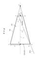
- FIG. 1 is an explanatory diagram showing an example of a detection device according to a first embodiment.
- FIG. 2A is an explanatory diagram showing example 1 of the incidence angle dependence of directly incident light on the detection device.
- FIG. 2B is an explanatory diagram showing example 2 of the incidence angle dependence of directly incident light on the detection device.
- FIG. 2C is an explanatory diagram showing example 3 of the incidence angle dependence of directly incident light on the detection device.
- FIG. 3 is an explanatory diagram showing the incidence angle dependence of direct incident light and reflected incident light on the detection device.
- FIG. 4 is an explanatory diagram showing another example of the structure inside the frustum portion.
- FIG. 5A is a partial side sectional view of the detection device according to the second embodiment.
- FIG. 5A is a partial side sectional view of the detection device according to the second embodiment.
- FIG. 5B is an external view showing two adjacent light guide sections.
- FIG. 6 is a partial plan view of the detection device according to the second embodiment.
- FIG. 7 is an explanatory diagram showing a first example of the arrangement spacing of a plurality of light guide parts.
- FIG. 8 is a graph showing MTF characteristics with respect to the arrangement angle and the incident angle of incident light.
- FIG. 9 is an explanatory diagram showing a second example of the arrangement spacing of a plurality of light guide parts.
- FIG. 10 is an explanatory diagram showing a third example of the arrangement spacing of a plurality of light guide parts.
- FIG. 11 is a partial plan view of the detection device according to the fourth embodiment.
- FIG. 12 is a perspective view of a detection device according to a fifth embodiment.
- FIG. 13 is a side view of the detection device according to the fifth embodiment.
- FIG. 14 is a plan view and an AB sectional view of the first holding plate.
- FIG. 15 is a plan view and a CD sectional view of the second holding plate.
- FIG. 16 is an explanatory diagram showing an example of a light guide component manufacturing system according to the sixth embodiment.
- FIG. 17 is a perspective view showing an example of a light guide component produced by the manufacturing system.
- FIG. 18 is an explanatory diagram showing an example of connection of light guide components.
- FIG. 19 is an explanatory diagram showing an example of another processing object.
- FIG. 20 is a front view and a plan view showing another example of a light guide component produced by the manufacturing system.
- FIG. 20 is a front view and a plan view showing another example of a light guide component produced by the manufacturing system.
- FIG. 21 is a front view and a bottom view showing another example of a light guide component produced by the manufacturing system.
- FIG. 22 is an explanatory diagram showing an example of connection of light guiding components.
- FIG. 23 is a perspective view showing an example of the structure according to the seventh embodiment.
- FIG. 24 is a first sectional view of the structure according to the seventh embodiment.
- FIG. 25 is a second sectional view of the structure according to the seventh embodiment.
- FIG. 26 is another first sectional view of the structure according to the seventh embodiment.
- FIG. 1 is an explanatory diagram showing an example of a detection device according to a first embodiment.
- the detection device 100 includes a light guide section 101 and a detection section 110.
- the light guide section 101 allows incident light from a subject to pass thereinto and outputs it to the detection section 110 .
- the detection unit 110 includes a photodiode, receives the light emitted from the light guide unit 101, and performs photoelectric conversion.
- the light guiding section 101 and the detecting section 110 will be specifically explained.
- the light guide section 101 includes a frustum section 102 and a transmission section 103.
- the frustum portion 102 and the transmission portion 103 may be connected or may be integrally formed.
- the frustum portion 102 has an entrance portion 121 at one end and an output portion 122 at the other end.
- the entrance part 121 has an entrance 121a and an edge 121b.
- the entrance aperture 121a is an aperture into which light enters, and its center is O1, and its aperture, which is the distance from the center O1 to the edge 121b, is r1.
- the edge 121b is the outline of the entrance aperture 121a.
- the incident light from the entrance 121 a is input into the frustum portion 102 .
- the surface of the entrance port 121a (aperture surface) and the area of the aperture surface are expressed as S1.
- the emission section 122 has an opening 122a communicating with one end of the transmission section 103 and an edge 122b. Let the center of the opening 122a be O2, and let the diameter, which is the distance from the center O2 to the edge 122b, be r2 ( ⁇ r1). Edge 122b is the outline of opening 122a. The light emitted from the aperture 122a is input into the transmission section 103. The surface of the opening 122a (opening surface) and the area of the opening surface are expressed as S2. The opening 122a has the same shape as the entrance port 121a.
- the inner circumferential surface of the frustum portion 102 may be an absorption surface that absorbs incident light or a reflective surface that reflects incident light. Furthermore, the inner surface of the frustum portion 102 may be filled with a transparent material that transmits light even though it is hollow.
- the frustum section 102 has a three-dimensional shape obtained by removing the cone whose apex is O and whose bottom surface is the opening 122a of the output section 122 from a cone whose apex is O and whose bottom surface is the entrance 121a of the input section 121. That is, the frustum portion 102 has a through hole 123 that penetrates from the entrance port 121a to the opening 122a.
- the vertex O does not necessarily exist on the surface 111 of the detection unit 110, in FIG. 1, the vertex O is arranged at the center of the surface 111 for convenience.
- L be the line segment connecting points O, O1, and O2.
- M be the generatrix of a cone whose apex is point O and whose bottom surface is the entrance 121a of the entrance section 121.
- the angle of incidence of the incident light with respect to the line segment L is assumed to be ⁇ .
- the angle between the line segment L and the generatrix M be ⁇ .
- the generatrix M is a line segment connecting the point O and the edge 121b of the incidence section 121.
- the transmission section 103 is a hollow column, that is, a cylinder. One end 131 of the transmission section 103 communicates with the emission section 122 . The other end 132 of the transmission section 103 has an exit port 132a that outputs the incident light to the detection section 110, and is connected to the detection section 110. The opening at one end 131 and the opening at the other end 132 of the transmission section 103 have the same shape and the same size. The inner surface of the transmission section 103 repeatedly undergoes total reflection and internal reflection to efficiently transmit incident light to the output section 122. A through hole from one end 131 to the other end 132 of the transmission section 103 is referred to as a transmission path 133.
- the detection unit 110 has a flat plate shape.
- a surface 111 of the detection section 110 is connected to the other end 132 of the transmission section 103.
- the inner surface of the surface 111 surrounded by the edge of the other end 132 becomes the light receiving surface 112 that receives the light transmitted within the transmission section 103 .
- a photoelectric conversion section is provided inside the light receiving surface 112.
- the detection unit 110 photoelectrically converts the light received by the light receiving surface 112 using a photodiode, and outputs an electrical signal.
- This photodiode is made of silicon or indium gallium arsenide, for example.
- the electrical signal is output to an image processing section (not shown).
- the image processing section performs image processing based on the electrical signal and displays the subject image on a display section (not shown). Note that the image processing section and the display section may be provided within the detection device 100, or may be provided outside the detection device 100 in a computer that can communicate with the detection device 100.
- the detection unit 110 may have a function of amplifying light.
- the transmission section 103 is a cylinder
- the light receiving surface 112 is approximately on the same plane and has the same area as the opening 122a of the emission section 122.
- S2 is sometimes referred to as a light-receiving area for convenience.
- the relationship between the opening area S1 and the light receiving area S2 is shown in the following equation (1).
- D S2/S1...(1) D is the light-receiving surface ratio.
- FIGS. 2A to 2C are explanatory diagrams showing examples 1 to 3 of the incidence angle dependence of directly incident light on the detection device 100.
- the frustum portion 102 is shown in a cross section perpendicular to the circumferential direction of the entrance 121a and the opening 122a.
- a and B are points on the edge 121b, and when AB is written, it indicates the area S1 or its surface.
- 200a to 200c are luminous fluxes. When 200a to 200c are not distinguished from each other, they are expressed as luminous flux 200.
- 201a to 201c, 202a, and 202b are light rays that define the edges of the light beam 200.
- 201a to 201c are not distinguished, they are referred to as rays 201.
- the light rays 202a and 202b are not distinguished, they are referred to as a light ray 202.
- A0 is the intersection of the ray 201 of the directly incident light from the subject and the aperture surface S1 of the entrance aperture 121a
- B0 is the intersection of the ray 202 of the directly incident light from the subject and the aperture surface S1 of the entrance aperture 121a. If there is, and it is written as A 0 B 0 , it indicates the area or surface where the luminous flux of the directly incident light A 0 to B 0 intersects with the aperture surface S1.
- A' and B' are points on the edge 122b, and when written as A'B', it indicates the area S2 or its surface.
- the subscript 0 of A 0 and B 0 indicates the number of times the light passing through A 0 and B 0 is reflected within the frustum portion 102 .
- the number of reflections is defined as i and j (i and j are non-negative integers) and expressed as A i and B j .
- the light beam 200 in FIG. 2A cannot all enter the entrance aperture 121a, and the light ray 201c enters the entrance aperture 121a. If ⁇ >> ⁇ is reached beyond this point, the light beam 200 will no longer be incident on the aperture 122a.
- FIG. 3 is an explanatory diagram showing the incidence angle dependence of direct incident light and reflected incident light on the detection device 100.
- the reflected light beams 300a-1u and 300a-1d (reflected incident light 300a-1 if these are not distinguished) are reflected incident light that enters from the entrance aperture 121a, is reflected once inside the frustum part 102, and reaches the aperture 122a. It is.
- the reflected light beam 300a-2 is reflected incident light that enters from the entrance 121a, is reflected twice inside the frustum portion 102, and reaches the aperture 122a.
- the reflected light beam 300a-1u passes through the surface A 0 A 1 .
- the reflected light beams 300a-1d pass through the plane B 0 B 1 .
- the reflected light beam 300a-2 passes through the surface A 1 A 2 .
- the light receiving angle characteristic considering reflected light is expressed by the following formula (3).
- R i is the reflectance at the i-th reflection inside the frustum portion 102 .
- R j is the reflectance at the j-th reflection inside the frustum portion 102 .
- the reflectances R i and R j decrease.
- FIG. 4 is an explanatory diagram showing another example of the internal configuration of the frustum portion 102.
- a light reception prevention member 402 is provided on at least a portion of the inner circumferential surface 401 of the frustum portion 102 .
- the light reception prevention member 402 reflects the incident light 400 and causes the incident light 400 to exit from the entrance aperture 121 a of the entrance section 121 .
- Each of the light reception prevention members 402 is an annular or arc-shaped member extending in the circumferential direction of the entrance port 121a and the opening 122a.
- the shape of the cross section of the light reception prevention member 402 perpendicular to the circumferential direction is, for example, similar to the shape of the cross section of the frustum portion 102 perpendicular to the circumferential direction.
- the light reception prevention member 402 has a first surface 421 and a second surface 422.
- the first surface 421 is a surface facing the entrance port 121a, and reflects the incident light to output from the entrance port 121a.
- the second surface 422 reflects the incident light and causes it to be emitted to the first surface 421 of the other light reception prevention member 402 on the opening 122a side.
- clear object detection can be achieved without using a lens. Further, according to the first embodiment, it is possible to realize object detection with high directivity, that is, a deep depth of field, and without the concept of focus.
- the shapes of the entrance port 121a and the opening 122a are circular, but they may be polygonal.
- the cross-sectional shapes of the frustum portion 102 and the transmission portion 103 perpendicular to the line segment L also have the same polygonal shape.
- a transparent member may be provided at the entrance port 121a.
- the transparent member by sealing the entrance port 121a with a transparent plastic member, it is possible to improve the dustproofness inside the frustum part 102 and the transmission part 103 while ensuring object detection.
- a transparent member by sealing the entrance port 121a with a lens, it is possible to improve the convergence of incident light and the dust-proof property inside the light guide section 101 while ensuring object detection. can be achieved.
- FIG. 5A is a partial side sectional view of the detection device according to the second embodiment.
- the detection device 500 has a hemispherical housing 501.
- the housing 501 has a hemispherical surface 502 and a bottom surface 503.
- the bottom surface 503 is a disk that seals the opening of the hemispherical surface 502.
- a detection processing section 510 is provided at the center on the bottom surface 503.
- the detection processing section 510 is a collection of detection sections 110 connected to each of the plurality of light guide sections 101.
- a region on the surface of the detection processing section 510 connected to each transmission section 103 constitutes a photodiode serving as the detection section 110, each serving as a pixel.
- This photodiode is arranged two-dimensionally. Note that the other end 132 of each transmission section 103 is configured such that the end surface of the other end 132 is parallel to the surface of the detection processing section 510.
- Each of the light guide sections 101 is provided radially from the detection processing section 510 toward the hemispherical surface 502. In FIG. 5, for convenience of explanation, five light guide sections 101 are provided radially. Adjacent frustum portions 102 are arranged apart from each other.
- the entrance aperture 121a is located on the hemispherical surface 502. An opening may be formed in the hemispherical surface 502 at the position of the entrance port 121a. Further, the hemispherical surface 502 may have a structure in which the entrance port 121a is sealed with a transparent member. The area of the hemispherical surface 502 other than the entrance port 121a may be formed of a light-shielding member.
- FIG. 5B is an external view showing two adjacent light guide sections 101.
- one of the two adjacent light guide sections 101 is a light guide section 101A
- the other is a light guide section 101B.
- the bus lines M adjacent to each other between the light guide portions 101A and 101B are referred to as bus lines MA and MB, respectively.
- the angle formed by the generatrix MA and MB and the arrangement angle between the light guide parts 101A and 101B are defined as the arrangement angle ⁇ .
- the direction (restriction) of the incident light can be narrowed by the lens, and the arrangement angle ⁇ can be made smaller than when there is no lens. Therefore, compared to the case where no lens is provided, more light guide sections 101 can be arranged, and high-resolution images can be obtained.
- FIG. 6 is a partial plan view of the detection device 500 according to the second embodiment.
- Both edges 121b and 122b are circles centered on points O1 and O2.
- the distance to the end (a position different from the end) is also the radius r1 of the edge 121b.
- the distance from point O2 to the first output end located on edge 122b is the radius r2 of edge 122b, and the distance from point O2 to the first output end located on edge 122b is the radius r2 of edge 122b. 1) is also the radius r2 of the edge 122b.
- FIG. 7 is an explanatory diagram showing a first example of the arrangement spacing of the plurality of light guide sections 101.
- the plurality of light guide sections 101 are arranged radially from the surface 700 of the detection processing section 510.
- the other end 132 of each transmission section 103 is connected to the surface 700 of the detection processing section 510.
- FIG. 8 is a graph showing MTF characteristics with respect to the arrangement angle ⁇ and the incident angle ⁇ of incident light.
- the horizontal axis is the incident angle ⁇ of incident light
- the vertical axis is MFT (Modulation Transfer Function).
- Waveforms 801 to 803 are MTF characteristics of each light guide section 101.
- the light guide section 101 of the waveform 801 and the light guide section 101 of the waveform 802 are adjacent to each other, and the light guide section 101 of the waveform 801 and the light guide section 101 of the waveform 803 are adjacent to each other.
- Waveforms 801 to 803 are formed with a period of 2 ⁇ + ⁇ . 2 ⁇ is the opening angle of the frustum portion 102.
- MTF is calculated by the following formula (4).
- MTF response within the opening angle (2 ⁇ ) of the light guide section 101 / (opening angle (2 ⁇ ) of the light guide section 101 + response outside the angle from the adjacent light guide section 101).
- the range of the incident angle ⁇ of the peak 802p of the waveform 802 includes the incident angle ⁇ of the tail 801hR of the waveform 801 (out-of-angle response from the adjacent light guide section 101), and the incident angle ⁇ of the peak 801p of the waveform 801 is included. ⁇ is not included.
- the range of the incident angle ⁇ of the peak 803p of the waveform 803 includes the incident angle ⁇ of the tail 801hL of the waveform 801 (out-of-angle response from the adjacent light guide section 101), and the range of the incident angle ⁇ of the peak 803p of the waveform 801 includes Angle ⁇ is not included.
- Embodiment 3 Next, Embodiment 3 will be described.
- the length in the longitudinal direction of the transmission section 103 is the same for each light guide section 101, but in the third embodiment, the length of each light guide section 101 differs depending on the arrangement position.
- Components that are the same as those in Embodiment 1 and Embodiment 2 are given the same reference numerals, and their descriptions will be omitted.
- FIG. 9 is an explanatory diagram showing a second example of the arrangement spacing of the plurality of light guide sections 101.
- each transmission section 103 is longer as it is located inside (the center of the detection processing section 510) within the detection device 500, and shorter as it is located outside.
- Each transmission section 103 is connected perpendicularly to the surface 700 of the detection processing section 510.
- the incident light is reflected within the transmitting section 103 and guided to the light receiving surface 112.
- the density of the transmission section 103 is reduced compared to the second embodiment, and it is possible to reduce the intrusion of incident light leaking from the adjacent light guide section 101.
- FIG. 10 is an explanatory diagram showing a third example of the arrangement spacing of the plurality of light guide sections 101.
- the transmission section 103 is not provided in some of the light guide sections 101, and the output section 122 of the light guide section 101 is directly connected to the surface 700 of the detection processing section 510.
- these portions of the light guide section 101 are referred to as light guide sections 101L and 101R.
- An edge 122bL of the output section 122 of the light guide section 101L is directly connected to the surface 700.
- the edge 122bR of the output section 122 of the light guide section 101R is also directly connected to the surface 700.
- the light guide parts 101L and 101R are determined so that the light emitted from all the light guide parts 101 can be received by the flat surface 700.
- the configuration of the light guide sections 101L and 101R in FIG. 10 is also applicable to the first embodiment.
- the edges 121b and 122b have a circular shape, but in the fifth embodiment, the edges 121b and 122b have a polygonal shape.
- Components that are the same as those in Embodiments 1 to 3 are given the same reference numerals, and their descriptions will be omitted.
- FIG. 11 is a partial plan view of the detection device 500 according to the fourth embodiment.
- the shape of the edge 121b is not a circle but a regular hexagon.
- the edges 121b and 122b are both regular hexagons centered on points O1 and O2.
- the distance from the point O1 to the first entrance end, which is the vertex on the edge 121b, is r1
- the distance from the point O1 to the second entrance end, which is the side on the edge 121b is s1( ⁇ r1).
- the distance from point O2 to the first output end, which is the apex on edge 122b, is r2
- the distance from point O2 to the second output end, which is the side on edge 122b is s2 ( ⁇ r2 ).
- the shapes of the edges 121b and 122b are regular hexagons, but they may be polygons other than regular hexagons as long as s1 ⁇ r1 and s2 ⁇ r2 are satisfied.
- the shapes of the edges 121b and 122b in the second to fourth embodiments are polygonal, but the shapes of the edges 121b and 122b in the first embodiment may be polygonal.
- the transmission section 103 is a hollow cylinder, the inner peripheral surface of the cylinder may be plated with metal to reflect light. Further, the transmission section 103 may be a cylinder having an optical fiber inside.
- one light guide section 101 is associated with one detection section 110 as an ommatidia, and the detection section 110 detects the intensity of the incident light from the light guide section 101. do.
- Each of the light guide parts 101 is optically isolated, and one light guide part 101 receives incident light from one direction (the direction of the line segment L), so that the plurality of light guide parts 101 can collectively create a wide range of images. The closer you get, the higher the resolution and more detailed images can be captured.
- Embodiment 5 Next, Embodiment 5 will be described.
- Embodiment 5 a configuration for holding a plurality of light guide sections 101 shown in Embodiments 1 to 4 will be described.
- Components that are the same as those in Embodiments 1 to 4 are given the same reference numerals, and their descriptions will be omitted.
- FIG. 12 is a perspective view of the detection device according to the fifth embodiment.
- FIG. 13 is a side view of the detection device according to the fifth embodiment. In FIG. 13, the light guide section 101 on the depth side is omitted.
- FIG. 14 is a plan view and an AB sectional view of the first holding plate.
- FIG. 15 is a plan view and a CD sectional view of the second holding plate.
- the detection device 1200 includes a plurality of light guide sections 101 (frustum section 102 and transmission section 103), a detection processing section 510, a first holding plate 1201, a second holding plate 1202 (in FIG. 12, for convenience, a second (retaining plate 1202 omitted).
- the plurality of light guide sections 101 are arranged in a matrix so that each incident section 121 is located on the same curved surface.
- the other end 132 of each transmission section 103 is connected to the detection processing section 510.
- the first holding plate 1201 and the second holding plate 1202 each hold a plurality of light guide parts 101.
- the first holding plate 1201 and the second holding plate 1202 are plate-shaped members. Although the first holding plate 1201 and the second holding plate 1202 are rectangular in shape, they may be polygonal or circular. Moreover, the first surface 1201a, the second surface 1202a, the first back surface 1201b, and the second back surface 1202b of the first holding plate 1201 and the second holding plate 1202 may be flat end surfaces or may be curved surfaces.
- the first holding plate 1201 and the second holding plate 1202 are each arranged to intersect with the longitudinal direction of the light guide section 101.
- the first holding plate 1201 is provided with a first through hole 1301 at a position intersecting with the frustum portion 102, into which the frustum portion 102 can be inserted.
- the second holding plate 1202 is provided with a second through hole 1302 at a position intersecting with the transmission section 103, into which the transmission section 103 can be inserted.
- the detection device 1200 has at least one of the first holding plate 1201 and the second holding plate 1202.
- the first holding plate 1201 has a plurality of first through holes 1301.
- the plurality of first through holes 1301 are provided at positions corresponding to the insertion positions of the plurality of frustum portions 102 arranged in a matrix.
- the first through hole 1301 has a first upper edge 1301a and a first lower edge 1301b.
- the first through hole 1301 is a hole that penetrates between the first upper edge 1301a and the first lower edge 1301b.
- the first upper edge 1301a is provided on the first surface 1201a, and the first lower edge 1301b is provided on the first back surface 1201b.
- the opening diameter of the first upper edge 1301a is larger than the opening diameter of the first lower edge 1301b.
- the emission part 122 of the frustum part 102 is inserted from the first upper edge 1301a and protrudes from the first lower edge 1301b, and the frustum part 102 is held in the first through hole 1301. Thereafter, the frustum section 102 held by the first holding plate 1201 through the first through hole 1301 is connected to the transmission section 103.
- the second holding plate 1202 has a plurality of second through holes 1302.
- the plurality of first through holes 1301 are provided at positions corresponding to insertion positions of the plurality of transmission sections 103 arranged in a matrix.
- the second through hole 1302 has a second upper edge 1302a and a second lower edge 1302b.
- the second through hole 1302 is a hole that penetrates between the second upper edge 1302a and the second lower edge 1302b.
- the second upper edge 1302a is provided on the second surface 1202a, and the second lower edge 1302b is provided on the second back surface 1202b.
- the opening diameter of the second upper edge 1302a is the same as the opening diameter of the second lower edge 1302b.
- the transmission section 103 before the transmission section 103 is connected to the frustum section 102 and the detection processing section 510, it may be inserted from the second upper edge 1302a and protruded from the second lower edge 1302b. and may be inserted from the second upper edge 1302a and protrude from the second upper edge 1302a.
- the transmission section 103 is inserted from the second upper edge 1302a and protruded from the second lower edge 1302b. Further, before the detection processing unit 510 is connected and after the transmission unit 103 is connected to the frustum portion 102, the transmission unit 103 is inserted from the second upper edge 1302a and protruded from the second lower edge 1302b.
- first holding plate 1201 and the second holding plate 1202 are held inside a casing (not shown) of the detection device 1200.
- the light guide section 101 is configured by the frustum section 102 and the transmission section 103, but the light guide section 101 may be configured only by the frustum section 102. In this case, the detection processing section 510 will be connected to the emission section 122.
- the frustum portion 102 is configured such that the opening diameter of the entrance port 121a is larger than the opening diameter of the exit portion 122, but even if the opening diameter of the entrance port 121a is made the same as the opening diameter of the exit portion 122, good. As a result, the frustum portion 102 has a cylindrical shape.
- the plurality of light guide sections 101 are held by at least one of the first holding plate 1201 and the second holding plate 1202, the plurality of light guide sections 101 are held. Positioning accuracy is improved. This facilitates manufacturing of the detection device 1200.
- Embodiment 6 Next, Embodiment 6 will be described. In Embodiment 6, a method for manufacturing a light guide section will be described. Components that are the same as those in Embodiments 1 to 5 are given the same reference numerals, and their descriptions will be omitted.
- FIG. 16 is an explanatory diagram showing an example of a light guide component manufacturing system according to the sixth embodiment.
- the manufacturing system 1600 includes a laser processing machine 1601, an XY stage 1602, and a control device 1603. Note that in FIG. 16, the X axis, Y axis, and Z axis are orthogonal to each other.
- the laser processing machine 1601 irradiates a processing object 1610 with laser light.
- the laser processing machine 1601 forms a groove by, for example, irradiating a processing object 1610 with a laser beam having a predetermined pulse width (for example, a femtosecond pulse) in the Z-axis direction and processing it into a desired shape.
- a predetermined pulse width for example, a femtosecond pulse
- the XY stage 1602 is a positioning table that is movable in the X axis and the Y axis perpendicular to the X axis.
- a workpiece 1610 is fixedly mounted on a mounting surface 1620 on the XY stage 1602 .
- the mounting surface 1620 is parallel to a plane defined by the X-axis and the Y-axis.
- a control device 1603 controls the irradiation time of the laser beam from the laser processing machine 1601 and controls the movement of the XY stage 1602. For example, the control device 1603 adjusts the depth of the groove formed in the Z-axis direction by increasing or decreasing the irradiation time of the laser beam from the laser processing machine 1601. For example, the control device 1603 can form a long groove in the Y direction in the workpiece 1610 with the laser beam from the laser processing machine 1601 by moving the XY stage 1602 in the Y direction, and the XY stage By moving 1602 in the X direction, the width of the long groove in the Y direction can be adjusted using the laser beam from the laser processing machine 1601.
- the size of the groove can be controlled by the power of the laser beam (irradiation diameter), the number of irradiation pulses (time), and the positional movement of the XY stage 1602.
- the irradiation time length and its fluctuation timing by controlling the irradiation time of the laser beam from the laser processing machine 1601, and the amount of movement and its timing by controlling the movement of the XY stage 1602 are set in advance in the control device 1603.
- the object to be processed 1610 is a workpiece made of metal, glass, or ceramics.
- the shape of the workpiece 1610 is, for example, a plate-like workpiece whose cross section in the YZ plane direction is a trapezoid.
- the oblique surface 1611 and back surface 1612 of the workpiece 1610 are surfaces irradiated with laser light from the laser processing machine 1601. For example, after the front surface 1611 is irradiated, the back surface 1612 is fixedly placed to face the laser processing machine 1601 by a person or by a mechanism not shown.
- control device 1603 controls the output of the laser processing machine 1601 to be higher in the thicker part of the workpiece 1610 in the Z-axis direction, and moves the XY stage 1602 so that the width of the groove in the X-axis direction becomes larger. Control.
- FIG. 17 is a perspective view showing an example of a light guide component produced by the manufacturing system 1600.
- Light guide component 1700 is generated by processing object 1610 by manufacturing system 1600. That is, first grooves 1711 and 1712 are formed on the front surface 1611 of the light guide component 1700, and second grooves 1721 to 1723 are formed on the back surface 1612.
- the first grooves 1711, 1712 and the second grooves 1721 to 1723 are, for example, substantially trapezoidal, and are processed so that the shape becomes smaller from the front end surface 1701 toward the rear end surface 1702.
- the first grooves 1711, 1712 and the second grooves 1721 to 1723 may have a semicircular shape.
- FIG. 18 is an explanatory diagram showing a connection example of the light guide component 1700.
- FIG. 18 shows a structure 1800 in which six light guide components 1700 are stacked in the Z-axis direction. Specifically, for example, six light guide components 1700 are stacked in the Z-axis direction by connecting the front surfaces 1611 or back surfaces 1612 of two light guide components 1700 adjacent to each other in the Z-axis direction. be done.
- the structure 1800 is a structure in which the first through hole 1801 and the second through hole 1802 are the light guide portion 101 or the frustum portion 102 .
- Two adjacent light guide components 1700 are connected, for example, by screwing or crimping. In the case of screwing, screw holes are formed to penetrate through the six light guide components 1700. Note that the shorter the pulse width of the laser beam, the more it is possible to suppress burrs generated on the front surface 1611 and the back surface 1612 of the workpiece 1610 during processing, and the more the gap between two adjacent light guide components 1700 can be suppressed. can.
- each light guide component 1700 becomes a light incident surface
- the rear end surface 1702 of each light guide component 1700 becomes a light exit surface.
- the plurality of connected front end surfaces 1701 will be referred to as an entrance surface 1701
- the plurality of connected rear end surfaces 1702 will be referred to as an exit surface 1702.
- the light enters through the openings of the first through hole 1801 and the second through hole 1802 formed on the entrance surface 1701, and is emitted from the openings of the first through hole 1801 and the second through hole 1802 formed on the exit surface 1702. Ru.
- the structure 1800 is applied to the detection device 100 as a plurality of light guide sections 101 as shown in the first to fourth embodiments described above. Specifically, for example, the output surface 1702 of the structure 1800 is connected to the detection processing section 510. More specifically, the detection unit 110 is connected to each of the openings of the first through hole 1801 and the second through hole 1802 on the exit surface 1702 side. Thereby, the light passing through the first through hole 1801 and the second through hole 1802 can be received.
- the structure 1800 may be applied to the detection device 100 as a plurality of frustum portions 102 as shown in the first to fourth embodiments described above.
- one end 131 of the transmission section 103 is connected to each of the openings of the first through hole 1801 and the second through hole 1802 on the emission surface 1702 side, and the detection section is connected to each of the other end 132 of the transmission section 103. 110 is connected.
- the light that has passed through the first through hole 1801, the second through hole 1802, and the transmission section 103 can be received.
- FIG. 19 is an explanatory diagram showing an example of another processing object.
- the workpiece 1910 has a rectangular parallelepiped shape and is different in shape from the workpiece 1610.
- a front surface 1911 and a back surface 1912 of the object to be processed 1910 are surfaces irradiated with laser light from the laser processing machine 1601.
- the back surface 1912 is fixedly placed to face the laser processing machine 1601 by a person or by a mechanism not shown.
- FIG. 20 is a front view and a plan view showing another example of a light guide component produced by the manufacturing system 1600.
- FIG. 21 is a front view and a bottom view showing another example of a light guide component produced by the manufacturing system 1600.
- the light guide component 2000 is generated by the manufacturing system 1600 processing the processing object 1910. That is, first grooves 2011 to 2013 are formed on the front surface 1911 of the light guide component 1900, and second grooves 2021 to 2023 are formed on the back surface 1912.
- the first grooves 2011 to 2013 and the second grooves 2021 to 2023 are, for example, approximately trapezoidal, and are processed so that their shapes become smaller from the front end surface 2001 toward the rear end surface 2002.
- U-shaped fitting grooves 2031 and 2032 are machined on both side edges of the surface 1911 of the light guide component 2000 along the Y-axis direction.
- Approximately U-shaped fitting protrusions 2041 and 2042 are formed on both edges of the back surface 1912 of the light guide component 2000 along the Y-axis direction.
- FIG. 22 is an explanatory diagram showing a connection example of the light guide component 2000.
- FIG. 22 shows a structure 2200 in which six light guide components 2000 are stacked in the Z-axis direction. Specifically, for example, six light guide components 2000 are stacked in the Z-axis direction by connecting the front surface 1911 and back surface 1912 of two light guide components 2000 adjacent in the Z-axis direction.
- the structure 2200 is a structure in which the through hole 2201 is the light guide portion 101 or the frustum portion 102 .
- the first grooves 2011 to 2013 and the second grooves 2021 to 2023 of each of the light guide components 2000 face each other, and the through hole is formed. 2201 is formed.
- the fitting protrusions 2041 and 2042 provided on the back surface 1912 of the upper light guide component 2000 of the two light guide components 2000 adjacent in the Z-axis direction are connected to the surface of the lower light guide component 2000. Fits into fitting grooves 2031 and 2032 provided in 1911. This restricts the displacement of the light guide component 2000 in the X-axis direction and the Y-axis direction, and improves the positioning accuracy of the through hole 2201.
- Two adjacent light guide components 2000 are connected, for example, by screwing or crimping.
- screw holes are formed to penetrate through the six light guide components 2000. Note that the shorter the pulse width of the laser beam is, the more burrs generated on the front surface 1911 and the back surface 1912 of the workpiece 1910 can be suppressed during processing, and the gap between two adjacent light guide components 2000 can be suppressed. can.
- each light guide component 2000 becomes a light incident surface
- the rear end surface 2002 of each light guide component 2000 becomes a light exit surface.
- the plurality of connected front end surfaces 2001 will be referred to as an entrance surface 2001
- the plurality of connected rear end surfaces 2002 will be referred to as an exit surface 2002.
- the structure 2200 is applied to the detection device 100 as a plurality of light guide sections 101 as shown in the first to fourth embodiments described above.
- the output surface 2202 of the structure 2200 is connected to the detection processing unit 510.
- the detection unit 110 is connected to each opening of the through hole 2201 on the exit surface 2202 side. Thereby, the light passing through the through hole 2201 can be received.
- Embodiment 7 shows a manufacturing method of manufacturing a light guide section by laminating plate members each having a plurality of through holes in the thickness direction.
- Components that are the same as those in Embodiments 1 to 4 are given the same reference numerals, and their descriptions will be omitted.
- FIG. 23 is a perspective view showing an example of a structure 2300 according to the seventh embodiment.
- FIG. 24 is a first cross-sectional view of a structure 2300 according to the seventh embodiment. The sectional view shown in FIG. 24 shows a cross section when the structure 2300 is cut at the cross section 2340 in FIG. 23.
- FIG. 25 is a second sectional view of the structure 2300 according to the seventh embodiment. The cross-sectional view shown in FIG. 25 shows a cross section when the structure 2300 is cut at the cross section 2350 in FIG. 23.
- the structure 2300 is generated by laminating a first plate member 2301 and a second plate member 2302.
- Let z be the stacking direction of the first plate member 2301 and the second plate member 2302.
- Let x and y be two axes perpendicular to z. It is assumed that x and y are orthogonal.
- first plate members 2301 there are seven first plate members 2301, but the number is not limited to seven. Although there are six second plate members 2302, the number is not limited to six. Further, the thickness of the first plate member 2301 is arbitrary, and different first plate members 2301 may have different thicknesses. Similarly, the thickness of the second plate-like member 2302 is arbitrary, and different second plate-like members 2302 may have different thicknesses. Further, the thickness of the first plate member 2301 and the thickness of the second plate member 2302 may be different.
- Each of the first plate members 2301 has a plurality of first through holes 2311 that penetrate approximately in the z direction. Furthermore, each of the first plate members 2301 has third through holes 2313 for positioning that penetrate in the z direction at its four corners. In each of the first plate members 2301, 81 first through holes 2311 are provided in a matrix. Note that the number of first through holes 2311 is not limited to 81, but the number of first through holes 2311 in the plurality of first plate members 2301 is the same.
- the bottom surface 2412 of one first plate member 2301 adjacent in the z direction contacts the top surface 2411 of the other first plate member 2301 arranged below.
- the first through hole 2311 of the one first plate member 2301 and the first through hole 2311 of the other first plate member 2301 communicate with each other.
- a first light guide path 2331 is formed.
- the first light guide paths 2331 are formed in the same number as the first through holes 2311 provided in one first plate member 2301 (81 in this example).
- the first light guide path 2331 is formed from the uppermost first plate member 2301 in the z direction to approach the center of the lowermost first plate member 2301. . Further, the first plate-like member 2301 is formed such that its opening diameter becomes shorter from the uppermost first plate-like member 2301 in the z direction to the center of the lowermost first plate-like member 2301.
- the first light guide path 2331 has a structure similar to the space inside the frustum portion 102 shown in Embodiments 1 to 4.
- the third through holes 2313 are provided at the same opening diameter and the same position in the first plate member 2301.
- a thread groove is formed on the inner peripheral surface of the third through hole 2313.
- Each of the second plate members 2302 has a plurality of second through holes 2322 that penetrate in the z direction. Furthermore, each of the second plate members 2302 has fourth through holes 2324 for positioning that penetrate in the z direction at its four corners. In each of the second plate members 2302, 81 second through holes 2322 are provided in a matrix. Note that the number of second through holes 2322 is not limited to 81, but the number of second through holes 2322 in the plurality of second plate members 2302 is the same.
- the second through holes 2322 are provided at the same opening diameter and at the same position in the plurality of second plate members 2302.
- the bottom surface 2422 of one of the second plate-like members 2302 adjacent in the z direction contacts the top surface 2421 of the other second plate-like member 2302 arranged below.
- the second through hole 2322 of the one second plate member 2302 and the second through hole 2322 of the other second plate member 2302 communicate with each other in the z direction.
- a second light guide path 2332 is formed.
- the second light guide paths 2332 are formed in the same number as the second through holes 2322 provided in one second plate member 2302 (81 in this example).
- the second light guide path 2332 has a structure similar to the cylindrical space inside the transmission section 103 shown in Embodiments 1 to 4.
- the fourth through hole 2324 is provided in the second plate member 2302 with the same opening diameter and the same position.
- the fourth through hole 2324 has the same shape and the same size as the third through hole 2313, and like the third through hole 2313, is provided at the four corners of the second plate member 2302.
- a thread groove is formed on the inner peripheral surface of the fourth through hole 2324.
- the first plate member 2301 in the lowest layer among the plurality of first plate members 2301 and the second plate member 2302 in the uppermost layer among the plurality of second plate members 2302 are connected. Specifically, for example, the bottom surface 2412 of the first plate-like member 2301 on the lowest layer and the top surface 2421 of the second plate-like member 2302 on the top layer are in contact with each other.
- the opening diameter of the first through hole 2311 on the bottom surface 2412 side of the first plate member 2301 in the lowermost layer is the same as the opening diameter of the second through hole 2322.
- the first through-hole 2311 of the first plate-like member 2301 on the lowest layer communicates with the second through-hole 2322 when the second plate-like member 2302 on the highest layer contacts the first plate-like member 2301 on the lowest layer. provided at the location. Therefore, by stacking the plurality of first plate-like members 2301 and the plurality of second plate-like members 2302, the first light guide path 2331 and the second light guide path 2332 communicate with each other. As a result, a through hole 2330 is formed.
- the third through hole 2313 of the first plate member 2301 of the lowest layer becomes the fourth through hole 2324 when the second plate member 2302 of the uppermost layer contacts the first plate member 2301 of the lowest layer.
- the first screw hole 2501 and the second screw hole 2502 communicate with each other.
- a fourth through hole 2314 is formed. Then, by screwing unillustrated screws into each of the four fourth through holes 2314, the plurality of first plate members 2301 and the plurality of second plate members 2302 are fixed.
- connections between first plate members 2301 adjacent in the z direction, between second plate members 2302 adjacent in the z direction, and between first plate members 2301 and second plate members adjacent in the z direction Structure 2300 may be generated by crimping with member 2302 .
- the first plate member 2301 is placed on the XY stage 1602 of the manufacturing system 1600 of the sixth embodiment, and the first through hole 2311 and the third through hole 2313 are formed by irradiating the laser beam from the laser processing machine 1601. be done.
- the XY stage 1602 may be tilted from the Z-axis direction so that the first plate member 2301 is tilted from the Z-axis direction, or the laser beam irradiation direction of the laser processing machine 1601 may be tilted from the Z-axis direction. do it.
- the second plate member 2302 is placed on the XY stage 1602 of the manufacturing system 1600, and the laser beam from the laser processing machine 1601 is irradiated to form the second through hole 2322 and the fourth through hole 2324. .
- the structure 2300 is applied to the detection device 100 as a plurality of light guide sections 101 as shown in the first to fourth embodiments described above.
- the bottom surface 2422 of the second plate member 2302 at the bottom of the structure 2300 is connected to the detection processing section 510.
- the detection unit 110 is connected to each opening of the second through hole 2322 on the bottom surface 2422 side of the second plate member 2302 in the lowermost layer. Thereby, the light passing through the first light guide path 2331 and the second light guide path 2332 can be received.
- the structure 2300 may be composed of a plurality of first plate members 2301 without using a plurality of second plate members 2302.
- the bottom surface 2412 of the first plate member 2301 at the lowest layer of the structure 2300 is connected to the detection processing section 510.
- the detection unit 110 is connected to each opening of the first through hole 2321 on the bottom surface 2412 side of the first plate member 2301 in the lowermost layer. Thereby, the light passing through the first light guide path 2331 can be received.
- the first light guide path 2331 is configured to be inclined toward the first light guide path 2331 at the center as it is located on the outer side, but the inner peripheral surface of the first light guide path 2331 is parallel to the z-axis. It may be formed as follows. This will be explained in detail below.
- FIG. 26 is another first cross-sectional view of the structure 2300 according to the seventh embodiment.
- the sectional view shown in FIG. 26 shows a cross section when the structure 2300 is cut at the cross section 2340 in FIG. 23.
- FIG. 26 differences from FIG. 24 will be mainly explained.
- Each of the first plate members 2301 has a plurality of first through holes 2611 that penetrate approximately in the z direction.
- 81 first through holes 2611 are provided in a matrix. Note that the number of first through holes 2611 is not limited to 81, but the number of first through holes 2611 in the plurality of first plate members 2301 is the same.
- the central first through hole 2611 has a larger opening diameter than the other first through holes 2611.
- the first light guide path 2631 formed by the first through hole 2611 at the center of each of the plurality of first plate members 2301 is referred to as the first light guide path 2631A, and the other first light guide paths 2631 are the first light guide path 2631A. It is assumed that the optical path is 2631B.
- the generatrix of the inner peripheral surface of the first through hole 2611 on both sides in the y direction has a stepped shape.
- the generatrix of the inner circumferential surface of the first through hole 2611 on the side away from the first light guide path 2631A has a stepped shape, similar to the first light guide path 2631A.
- the generatrix of the inner peripheral surface of the first through hole 2611 on the side closer to the first light guide path 2631A is a straight line.
- the first light guide paths 2631A and 2631B are provided with a step, they have the same function as the light reception prevention member 402 of the first embodiment. Therefore, the incident light can be reflected like the light reception prevention member 402.
- the first plate member 2301 is placed on the XY stage 1602 of the manufacturing system 1600 of the sixth embodiment, and the first through hole 2611 and the third through hole 2313 are formed by irradiating the laser beam from the laser processing machine 1601. be done.
- the second plate member 2302 is placed on the XY stage 1602 of the manufacturing system 1600, and the laser beam from the laser processing machine 1601 is irradiated to form the second through hole 2622 and the fourth through hole 2324. Ru.
- the first through hole 2611 penetrates in the direction (z direction) perpendicular to the upper surface 2411 of the first plate member 2301. Therefore, in the manufacturing system 1600, the laser beam from the laser processing machine 1601 can be irradiated perpendicularly to the upper surface 2411, which facilitates processing control in the manufacturing system 1600.
- first through hole 2611 and the third through hole 2313 may be created by drilling the first plate member 2301.
- second through hole 2612 and the fourth through hole 2314 may be created by drilling the second plate member 2302.
- 100 detection device 101 light guide section, 102 frustum section, 103 transmission section, 110 detection section, 112 light-receiving surface, 121 incident section, 121a entrance port, 123 through hole, 132a exit port, 133 transmission path, 401 inner peripheral surface , 402 light reception prevention member, 500 detection device, 510 detection unit
Abstract
In order to detect a subject without having a lens, this detection device comprises: a light guide part that has a light incidence port and an emission port having an opening smaller than that of the incidence port, and emits light incident from the incidence port from the emission port; and a detection part that detects the light emitted from the emission port.
Description
本出願は、令和4年(2022年)8月19日に出願された日本出願である特願2022-131239の優先権を主張し、その内容を参照することにより、本出願に取り込む。
This application claims priority to Japanese Patent Application No. 2022-131239, which was filed on August 19, 2022, and its contents are incorporated into this application by reference.
本発明は、検出装置に関する。
The present invention relates to a detection device.
撮像素子からの信号により被写体検出を行う技術を搭載した撮像装置が知られている。従来から被写体検出の精度向上が要求されていた。
Imaging devices are known that are equipped with a technology that detects a subject using a signal from an image sensor. There has been a long-standing demand for improved accuracy in object detection.
本開示技術の一側面である検出装置は、光の入射口と前記入射口よりも開口が小さい出射口とを有し、前記入射口から入射された光を前記出射口から出射する導光部と、前記出射口から出射された光を検出する検出部と、を有する。
A detection device that is an aspect of the presently disclosed technology includes a light input port and an output port having a smaller opening than the input port, and a light guide portion that emits light incident from the input port from the output port. and a detection unit that detects the light emitted from the emission aperture.
[実施形態1]
図1は、実施形態1にかかる検出装置の一例を示す説明図である。検出装置100は、導光部101と、検出部110と、を有する。導光部101は、被写体からの入射光をその内部に通過させて検出部110に出射する。検出部110は、フォトダイオードを有し、導光部101から出射された光を受光して、光電変換する。導光部101および検出部110について具体的に説明する。 [Embodiment 1]
FIG. 1 is an explanatory diagram showing an example of a detection device according to a first embodiment. Thedetection device 100 includes a light guide section 101 and a detection section 110. The light guide section 101 allows incident light from a subject to pass thereinto and outputs it to the detection section 110 . The detection unit 110 includes a photodiode, receives the light emitted from the light guide unit 101, and performs photoelectric conversion. The light guiding section 101 and the detecting section 110 will be specifically explained.
図1は、実施形態1にかかる検出装置の一例を示す説明図である。検出装置100は、導光部101と、検出部110と、を有する。導光部101は、被写体からの入射光をその内部に通過させて検出部110に出射する。検出部110は、フォトダイオードを有し、導光部101から出射された光を受光して、光電変換する。導光部101および検出部110について具体的に説明する。 [Embodiment 1]
FIG. 1 is an explanatory diagram showing an example of a detection device according to a first embodiment. The
導光部101は、錐台部102と、伝送部103と、を有する。錐台部102と伝送部103とは接続されていてもよく、一体形成されていてもよい。錐台部102は、錐台部102は、一端に入射部121を有し、他端に出射部122を有する。
The light guide section 101 includes a frustum section 102 and a transmission section 103. The frustum portion 102 and the transmission portion 103 may be connected or may be integrally formed. The frustum portion 102 has an entrance portion 121 at one end and an output portion 122 at the other end.
入射部121は、入射口121aと端縁121bとを有する。入射口121aは、光が入射される開口であり、その中心をO1とし、中心O1から端縁121bまでの距離である口径をr1とする。端縁121bは入射口121aの輪郭である。入射口121aからの入射光は錐台部102の内部に入射される。入射口121aの面(開口面)および開口面の面積をS1と表記する。
The entrance part 121 has an entrance 121a and an edge 121b. The entrance aperture 121a is an aperture into which light enters, and its center is O1, and its aperture, which is the distance from the center O1 to the edge 121b, is r1. The edge 121b is the outline of the entrance aperture 121a. The incident light from the entrance 121 a is input into the frustum portion 102 . The surface of the entrance port 121a (aperture surface) and the area of the aperture surface are expressed as S1.
出射部122は、伝送部103の一端に連通する開口122aと端縁122bとを有する。開口122aの中心をO2とし、中心O2から端縁122bまでの距離である口径をr2(<r1)とする。端縁122bは開口122aの輪郭である。開口122aからの出射光は伝送部103の内部に入射される。開口122aの面(開口面)および開口面の面積をS2と表記する。開口122aは、入射口121aと同一形状である。
The emission section 122 has an opening 122a communicating with one end of the transmission section 103 and an edge 122b. Let the center of the opening 122a be O2, and let the diameter, which is the distance from the center O2 to the edge 122b, be r2 (<r1). Edge 122b is the outline of opening 122a. The light emitted from the aperture 122a is input into the transmission section 103. The surface of the opening 122a (opening surface) and the area of the opening surface are expressed as S2. The opening 122a has the same shape as the entrance port 121a.
錐台部102の内周面は、入射光を吸収する吸収面でもよく、入射光を反射させる反射面でもよい。また、錐台部102の内面は、中空でも光を通す透明体で満たしてもよい。
The inner circumferential surface of the frustum portion 102 may be an absorption surface that absorbs incident light or a reflective surface that reflects incident light. Furthermore, the inner surface of the frustum portion 102 may be filled with a transparent material that transmits light even though it is hollow.
ここで、錐台部102は、頂点をOとし底面を入射部121の入射口121aとした円錐から、頂点をOとし底面を出射部122の開口122aとした円錐を取り除いた立体形状である。すなわち、錐台部102は、入射口121aから開口122aに貫通する貫通孔123を有する。頂点Oは、検出部110の表面111上に存在するとは限らないが、図1では便宜的に表面111の中心に頂点Oを配置した。
Here, the frustum section 102 has a three-dimensional shape obtained by removing the cone whose apex is O and whose bottom surface is the opening 122a of the output section 122 from a cone whose apex is O and whose bottom surface is the entrance 121a of the input section 121. That is, the frustum portion 102 has a through hole 123 that penetrates from the entrance port 121a to the opening 122a. Although the vertex O does not necessarily exist on the surface 111 of the detection unit 110, in FIG. 1, the vertex O is arranged at the center of the surface 111 for convenience.
点O、O1、O2を結ぶ線分をLとする。また、頂点を点Oとし底面を入射部121の入射口121aとした円錐の母線をMとする。線分Lに対する入射光の入射角をθとする。線分Lと母線Mとがなす角度をφとする。母線Mは、点Oと入射部121の端縁121bとを結ぶ線分である。
Let L be the line segment connecting points O, O1, and O2. Furthermore, let M be the generatrix of a cone whose apex is point O and whose bottom surface is the entrance 121a of the entrance section 121. The angle of incidence of the incident light with respect to the line segment L is assumed to be θ. Let the angle between the line segment L and the generatrix M be φ. The generatrix M is a line segment connecting the point O and the edge 121b of the incidence section 121.
伝送部103は、内部が中空の柱体、すなわち、筒体である。伝送部103の一端131は出射部122と連通する。伝送部103の他端132は、入射光を検出部110に出射する出射口132aを有し、検出部110に接続される。伝送部103の一端131の開口と他端132の開口とは同一形状でかつ同一の大きさである。伝送部103の内面は全反射、内面反射を繰り返して入射光を効率よく出射部122に伝達する。伝送部103の一端131から他端132への貫通孔を伝送路133と称す。
The transmission section 103 is a hollow column, that is, a cylinder. One end 131 of the transmission section 103 communicates with the emission section 122 . The other end 132 of the transmission section 103 has an exit port 132a that outputs the incident light to the detection section 110, and is connected to the detection section 110. The opening at one end 131 and the opening at the other end 132 of the transmission section 103 have the same shape and the same size. The inner surface of the transmission section 103 repeatedly undergoes total reflection and internal reflection to efficiently transmit incident light to the output section 122. A through hole from one end 131 to the other end 132 of the transmission section 103 is referred to as a transmission path 133.
検出部110は、平板形状である。検出部110の表面111は、伝送部103の他端132と接続される。表面111のうち他端132の端縁に囲まれた内部の面が、伝送部103内を伝送する光を受光する受光面112となる。受光面112内部には光電変化部が設けられる。
The detection unit 110 has a flat plate shape. A surface 111 of the detection section 110 is connected to the other end 132 of the transmission section 103. The inner surface of the surface 111 surrounded by the edge of the other end 132 becomes the light receiving surface 112 that receives the light transmitted within the transmission section 103 . A photoelectric conversion section is provided inside the light receiving surface 112.
検出部110は、受光面112で受光された光をフォトダイオードで光電変換して、電気信号を出力する。このフォトダイオードは、たとえば、シリコンまたはインジウムガリウム砒素で構成されている。電気信号は図示しない画像処理部に出力される。画像処理部は、電気信号に基づいて画像処理を実行し、図示しない表示部に被写体画像を表示する。なお、画像処理部および表示部は、検出装置100内に設けられていてもよく、検出装置100外で検出装置100と通信可能なコンピュータ内に設けられていてもよい。検出部110は光を増幅する機能を有していてもよい。
The detection unit 110 photoelectrically converts the light received by the light receiving surface 112 using a photodiode, and outputs an electrical signal. This photodiode is made of silicon or indium gallium arsenide, for example. The electrical signal is output to an image processing section (not shown). The image processing section performs image processing based on the electrical signal and displays the subject image on a display section (not shown). Note that the image processing section and the display section may be provided within the detection device 100, or may be provided outside the detection device 100 in a computer that can communicate with the detection device 100. The detection unit 110 may have a function of amplifying light.
なお、伝送部103は筒体であるため、受光面112は、出射部122の開口122aと略同一平面、同一面積である。このため、S2を便宜的に受光面積と称すことがある。また、開口面積S1と受光面積S2との関係を下記式(1)に示す。
Note that since the transmission section 103 is a cylinder, the light receiving surface 112 is approximately on the same plane and has the same area as the opening 122a of the emission section 122. For this reason, S2 is sometimes referred to as a light-receiving area for convenience. Further, the relationship between the opening area S1 and the light receiving area S2 is shown in the following equation (1).
D=S2/S1・・・(1)
Dは、受光面比率である。 D=S2/S1...(1)
D is the light-receiving surface ratio.
Dは、受光面比率である。 D=S2/S1...(1)
D is the light-receiving surface ratio.
図2A~図2Cは、検出装置100への直接入射光の入射角依存性の例1~3を示す説明図である。図2A~図2C(図3、図4も同様)では、錐台部102を、入射口121a、開口122aの周方向に直交する断面で示している。A、Bは端縁121b上の点であり、ABと表記した場合は、面積S1またはその面を示す。図2A~図2Cにおいて、200a~200cは光束である。200a~200cを区別しない場合は光束200と表記する。201a~201c、202a、202bは、光束200の端縁を規定する光線である。201a~201cを区別しない場合は光線201と表記する。光線202a、202bを区別しない場合は光線202と表記する。
FIGS. 2A to 2C are explanatory diagrams showing examples 1 to 3 of the incidence angle dependence of directly incident light on the detection device 100. 2A to 2C (as well as FIGS. 3 and 4), the frustum portion 102 is shown in a cross section perpendicular to the circumferential direction of the entrance 121a and the opening 122a. A and B are points on the edge 121b, and when AB is written, it indicates the area S1 or its surface. In FIGS. 2A to 2C, 200a to 200c are luminous fluxes. When 200a to 200c are not distinguished from each other, they are expressed as luminous flux 200. 201a to 201c, 202a, and 202b are light rays that define the edges of the light beam 200. When 201a to 201c are not distinguished, they are referred to as rays 201. When the light rays 202a and 202b are not distinguished, they are referred to as a light ray 202.
A0は被写体からの直接入射光の光線201と入射口121aの開口面S1との交点であり、B0は被写体からの直接入射光の光線202と入射口121aの開口面S1との交点であり、A0B0と表記した場合は、直接入射光A0~B0までの光束と開口面S1とが交わる面積またはその面を示す。A´、B´は端縁122b上の点であり、A´B´と表記した場合は、面積S2またはその面を示す。
A0 is the intersection of the ray 201 of the directly incident light from the subject and the aperture surface S1 of the entrance aperture 121a, and B0 is the intersection of the ray 202 of the directly incident light from the subject and the aperture surface S1 of the entrance aperture 121a. If there is, and it is written as A 0 B 0 , it indicates the area or surface where the luminous flux of the directly incident light A 0 to B 0 intersects with the aperture surface S1. A' and B' are points on the edge 122b, and when written as A'B', it indicates the area S2 or its surface.
なお、A0、B0の添え字の0は、A0、B0を通過する光の錐台部102内での反射回数を示す。一般化する場合、反射回数をi、j(i、jは非負整数)とし、Ai、Bjと表記する。
Note that the subscript 0 of A 0 and B 0 indicates the number of times the light passing through A 0 and B 0 is reflected within the frustum portion 102 . When generalizing, the number of reflections is defined as i and j (i and j are non-negative integers) and expressed as A i and B j .
(a)は、θ≦φの場合の入射角依存性、(b)は、θ>φの場合の入射角依存性、(c)は、θ>>φの場合の入射角依存性を示す。(a)の場合、面積A0B0の光束200aは、錐台部102の内部で反射せずに開口122aに到達する。すなわち、(a)では、面積A0B0=S2である。したがって、(a)における直射での受光角度特性I0(θ)は、下記式(2)で表現される。
(a) shows the incident angle dependence when θ≦φ, (b) shows the incident angle dependence when θ>φ, and (c) shows the incident angle dependence when θ>>φ. . In the case of (a), the light beam 200a having an area A 0 B 0 reaches the aperture 122a without being reflected inside the frustum portion 102. That is, in (a), the area A 0 B 0 =S2. Therefore, the light reception angle characteristic I 0 (θ) in direct sunlight in (a) is expressed by the following equation (2).
I0(θ)=A0B0/AB=A´B´/AB・・・(2)
I 0 (θ)=A 0 B 0 /AB=A'B'/AB...(2)
図2Bの場合、図2Aの光束200aがすべて入射口121aに入射できず、一部欠落した光束200bが入射口121aに入射される。したがって、光線202bが開口122aに入射されると、Bでケラレが発生する。面積A0B0の光束200bは、錐台部102の内部で反射せずに開口122aに到達する。すなわち、図2Bでは、面積A0B0<S2である。
In the case of FIG. 2B, all of the luminous flux 200a in FIG. 2A cannot enter the entrance aperture 121a, and a partially missing luminous flux 200b enters the entrance aperture 121a. Therefore, when the light beam 202b is incident on the aperture 122a, vignetting occurs at B. The light beam 200b having an area A 0 B 0 reaches the aperture 122a without being reflected inside the frustum portion 102. That is, in FIG. 2B, the area A 0 B 0 <S2.
図2Cの場合、図2Aの光束200がすべて入射口121aに入射できず、光線201cが入射口121aに入射される。これ以上、θ>>φになると、光束200が開口122aに入射されなくなる。
In the case of FIG. 2C, the light beam 200 in FIG. 2A cannot all enter the entrance aperture 121a, and the light ray 201c enters the entrance aperture 121a. If θ>>φ is reached beyond this point, the light beam 200 will no longer be incident on the aperture 122a.
図3は、検出装置100への直接入射光および反射入射光の入射角依存性を示す説明図である。反射光束300a-1u、300a-1d(これらを区別しない場合は反射入射光300a-1)は、入射口121aから入射され錐台部102内部で1回反射されて開口122aに到達する反射入射光である。反射光束300a-2は、入射口121aから入射され錐台部102内部で2回反射されて開口122aに到達する反射入射光である。
FIG. 3 is an explanatory diagram showing the incidence angle dependence of direct incident light and reflected incident light on the detection device 100. The reflected light beams 300a-1u and 300a-1d (reflected incident light 300a-1 if these are not distinguished) are reflected incident light that enters from the entrance aperture 121a, is reflected once inside the frustum part 102, and reaches the aperture 122a. It is. The reflected light beam 300a-2 is reflected incident light that enters from the entrance 121a, is reflected twice inside the frustum portion 102, and reaches the aperture 122a.
反射光束300a-1uは、面A0A1を通過する。反射光束300a-1dは、面B0B1を通過する。反射光束300a-2は、面A1A2を通過する。
The reflected light beam 300a-1u passes through the surface A 0 A 1 . The reflected light beams 300a-1d pass through the plane B 0 B 1 . The reflected light beam 300a-2 passes through the surface A 1 A 2 .
反射光を考慮した受光角度特性は、下記式(3)で表現される。
The light receiving angle characteristic considering reflected light is expressed by the following formula (3).

上記式(3)において、Riは錐台部102内部でのi回目の反射での反射率である。Rjは錐台部102内部でのj回目の反射での反射率である。反射回数i,jが増加するほど反射率Ri、Rjは低下する。
In the above formula (3), R i is the reflectance at the i-th reflection inside the frustum portion 102 . R j is the reflectance at the j-th reflection inside the frustum portion 102 . As the number of reflections i, j increases, the reflectances R i and R j decrease.
図4は、錐台部102内部の他の構成例を示す説明図である。錐台部102の内周面401の少なくとも一部に、受光防止部材402が設けられている。受光防止部材402は、入射光400を反射して、入射光400を入射部121の入射口121aから出射させる。受光防止部材402の各々は、入射口121a、開口122aの周方向に延在する環状または円弧形状の部材である。受光防止部材402の当該周方向に直交する断面の形状は、たとえば、錐台部102の当該周方向に直交する断面の形状と相似形である。
FIG. 4 is an explanatory diagram showing another example of the internal configuration of the frustum portion 102. A light reception prevention member 402 is provided on at least a portion of the inner circumferential surface 401 of the frustum portion 102 . The light reception prevention member 402 reflects the incident light 400 and causes the incident light 400 to exit from the entrance aperture 121 a of the entrance section 121 . Each of the light reception prevention members 402 is an annular or arc-shaped member extending in the circumferential direction of the entrance port 121a and the opening 122a. The shape of the cross section of the light reception prevention member 402 perpendicular to the circumferential direction is, for example, similar to the shape of the cross section of the frustum portion 102 perpendicular to the circumferential direction.
図4に示すように、受光防止部材402は、第1面421と、第2面422と、を有する。第1面421は、入射口121aと対向する面であり、入射光を反射して入射口121aから出射させる。第2面422は、入射光を反射して、開口122a側の他の受光防止部材402の第1面421に出射させる。
As shown in FIG. 4, the light reception prevention member 402 has a first surface 421 and a second surface 422. The first surface 421 is a surface facing the entrance port 121a, and reflects the incident light to output from the entrance port 121a. The second surface 422 reflects the incident light and causes it to be emitted to the first surface 421 of the other light reception prevention member 402 on the opening 122a side.
このように、実施形態1によれば、レンズを用いなくても鮮明な被写体検出を実現することができる。また、実施形態1によれば、指向性の高い、すなわち、被写界深度が深く、ピントの概念を持たない被写体検出を実現することができる。
As described above, according to the first embodiment, clear object detection can be achieved without using a lens. Further, according to the first embodiment, it is possible to realize object detection with high directivity, that is, a deep depth of field, and without the concept of focus.
なお、実施形態1では、一例として入射口121a、開口122aの形状を円形としたが多角形でもよい。この場合、錐台部102および伝送部103の線分Lに直交する断面形状も、同じ多角形となる。
Note that in the first embodiment, as an example, the shapes of the entrance port 121a and the opening 122a are circular, but they may be polygonal. In this case, the cross-sectional shapes of the frustum portion 102 and the transmission portion 103 perpendicular to the line segment L also have the same polygonal shape.
また、実施形態1において、入射口121aに透明部材を設けてもよい。透明部材の一例として、透明なプラスティック部材で入射口121aを封止することで、被写体検出を担保しつつ、錐台部102および伝送部103内部の防塵性の向上を図ることができる。また、透明部材の一例として、レンズで入射口121aを封止することで、被写体検出を担保しつつ、入射光の集光性の向上と、導光部101内部の防塵性の向上と、を図ることができる。
Furthermore, in the first embodiment, a transparent member may be provided at the entrance port 121a. As an example of the transparent member, by sealing the entrance port 121a with a transparent plastic member, it is possible to improve the dustproofness inside the frustum part 102 and the transmission part 103 while ensuring object detection. Furthermore, as an example of a transparent member, by sealing the entrance port 121a with a lens, it is possible to improve the convergence of incident light and the dust-proof property inside the light guide section 101 while ensuring object detection. can be achieved.
[実施形態2]
つぎに、実施形態2について説明する。実施形態1では、導光部101が1つの場合を例に挙げて説明したが、実施形態2では、導光部101が複数設けられた例について説明する。実施形態1と同一構成には同一符号を付し、その説明を省略する。 [Embodiment 2]
Next, a second embodiment will be described. In the first embodiment, a case in which there is onelight guide section 101 has been described as an example, but in a second embodiment, an example in which a plurality of light guide sections 101 are provided will be described. Components that are the same as those in Embodiment 1 are given the same reference numerals, and their descriptions will be omitted.
つぎに、実施形態2について説明する。実施形態1では、導光部101が1つの場合を例に挙げて説明したが、実施形態2では、導光部101が複数設けられた例について説明する。実施形態1と同一構成には同一符号を付し、その説明を省略する。 [Embodiment 2]
Next, a second embodiment will be described. In the first embodiment, a case in which there is one
図5Aは、実施形態2にかかる検出装置の部分側断面図である。検出装置500は、半球状の筐体501を有する。筐体501は、半球面502と底面503とを有する。底面503は、半球面502の開口を封止する円板である。筐体501内部において、底面503上の中央には検出処理部510が設けられる。
FIG. 5A is a partial side sectional view of the detection device according to the second embodiment. The detection device 500 has a hemispherical housing 501. The housing 501 has a hemispherical surface 502 and a bottom surface 503. The bottom surface 503 is a disk that seals the opening of the hemispherical surface 502. Inside the housing 501, a detection processing section 510 is provided at the center on the bottom surface 503.
検出処理部510は、複数の導光部101の各々と接続される検出部110の集合体である。各伝送部103と接続される検出処理部510の表面上の領域が各々画素となる検出部110であるフォトダイオードを構成する。このフォトダイオードは2次元配置される。なお、各伝送部103の他端132は、他端132の端面が検出処理部510の表面と平行となるように構成される。
The detection processing section 510 is a collection of detection sections 110 connected to each of the plurality of light guide sections 101. A region on the surface of the detection processing section 510 connected to each transmission section 103 constitutes a photodiode serving as the detection section 110, each serving as a pixel. This photodiode is arranged two-dimensionally. Note that the other end 132 of each transmission section 103 is configured such that the end surface of the other end 132 is parallel to the surface of the detection processing section 510.
導光部101の各々は、検出処理部510から半球面502に向かって放射状に設けられている。図5では、説明の便宜上、5個の導光部101が放射状に設けられている。隣り合う錐台部102は、離間して配置される。入射口121aは、半球面502に位置する。半球面502の入射口121aの位置に、開口が形成されていてもよい。また、半球面502は、透明部材で入射口121aを封止する構造でもよい。半球面502のうち入射口121a以外の領域は、遮光性部材で形成されていてもよい。
Each of the light guide sections 101 is provided radially from the detection processing section 510 toward the hemispherical surface 502. In FIG. 5, for convenience of explanation, five light guide sections 101 are provided radially. Adjacent frustum portions 102 are arranged apart from each other. The entrance aperture 121a is located on the hemispherical surface 502. An opening may be formed in the hemispherical surface 502 at the position of the entrance port 121a. Further, the hemispherical surface 502 may have a structure in which the entrance port 121a is sealed with a transparent member. The area of the hemispherical surface 502 other than the entrance port 121a may be formed of a light-shielding member.
図5Bは、隣り合う2つの導光部101を示す外観図である。図5Bにおいて、隣り合う2つの導光部101の一方を導光部101A、他方を導光部101Bとする。また、導光部101A、101B間の近接しあう母線Mをそれぞれ、母線MA、MBとする。母線MA、MBがなす角度を導光部101A、101B間の配置角度を配置角度δとする。
FIG. 5B is an external view showing two adjacent light guide sections 101. In FIG. 5B, one of the two adjacent light guide sections 101 is a light guide section 101A, and the other is a light guide section 101B. Further, the bus lines M adjacent to each other between the light guide portions 101A and 101B are referred to as bus lines MA and MB, respectively. The angle formed by the generatrix MA and MB and the arrangement angle between the light guide parts 101A and 101B are defined as the arrangement angle δ.
入射口121aにレンズを加える場合、入射光の方向(制限)はレンズで狭くすることが可能となり、レンズがない場合に比べて配置角度δをより小さくすることが可能になる。したがって、レンズを設けない場合に比べて、より多くの導光部101の配置が可能になり、高解像の画像取得が可能になる。
When adding a lens to the entrance aperture 121a, the direction (restriction) of the incident light can be narrowed by the lens, and the arrangement angle δ can be made smaller than when there is no lens. Therefore, compared to the case where no lens is provided, more light guide sections 101 can be arranged, and high-resolution images can be obtained.
図6は、実施形態2にかかる検出装置500の部分平面図である。端縁121b、122bはともに点O1、O2を中心とする円である。点O1から端縁121b上の位置である第1入射端部までの距離は端縁121bの半径r1であり、点O1から端縁121b上の位置である第2入射端部(第1入射端部とは異なる位置)までの距離も端縁121bの半径r1である。同様に、点O2から端縁122b上の位置である第1出射端部までの距離は端縁122bの半径r2であり、点O2から端縁122b上の位置である第1出射端部(第1出射端部とは異なる位置)までの距離も端縁122bの半径r2である。
FIG. 6 is a partial plan view of the detection device 500 according to the second embodiment. Both edges 121b and 122b are circles centered on points O1 and O2. The distance from the point O1 to the first incident end, which is a position on the edge 121b, is the radius r1 of the edge 121b, and the distance from the point O1 to the second incident end, which is a position on the edge 121b, is the radius r1 of the edge 121b. The distance to the end (a position different from the end) is also the radius r1 of the edge 121b. Similarly, the distance from point O2 to the first output end located on edge 122b is the radius r2 of edge 122b, and the distance from point O2 to the first output end located on edge 122b is the radius r2 of edge 122b. 1) is also the radius r2 of the edge 122b.
図7は、複数の導光部101の配置間隔例1を示す説明図である。複数の導光部101は、検出処理部510の表面700から放射状に配置される。各伝送部103の他端132は、検出処理部510の表面700に接続される。
FIG. 7 is an explanatory diagram showing a first example of the arrangement spacing of the plurality of light guide sections 101. The plurality of light guide sections 101 are arranged radially from the surface 700 of the detection processing section 510. The other end 132 of each transmission section 103 is connected to the surface 700 of the detection processing section 510.
図8は、配置角度δと入射光の入射角度θとに対するMTF特性を示すグラフである。グラフ800において、横軸は、入射光の入射角度θであり、縦軸はMFT(Modulation Transfer Function)である。波形801~803は、各導光部101のMTF特性である。波形801の導光部101と波形802の導光部101とは隣り合っており、波形801の導光部101と波形803の導光部101とは隣り合っている。波形801~803は、2φ+δ周期で形成されている。2φは、錐台部102の開き角である。
FIG. 8 is a graph showing MTF characteristics with respect to the arrangement angle δ and the incident angle θ of incident light. In the graph 800, the horizontal axis is the incident angle θ of incident light, and the vertical axis is MFT (Modulation Transfer Function). Waveforms 801 to 803 are MTF characteristics of each light guide section 101. The light guide section 101 of the waveform 801 and the light guide section 101 of the waveform 802 are adjacent to each other, and the light guide section 101 of the waveform 801 and the light guide section 101 of the waveform 803 are adjacent to each other. Waveforms 801 to 803 are formed with a period of 2φ+δ. 2φ is the opening angle of the frustum portion 102.
MTFは、下記式(4)により算出される。
MTF is calculated by the following formula (4).
MTF=導光部101の開き角(2φ)内応答/(導光部101の開き角(2φ)+隣りの導光部101からの角度外応答)・・・(4)
MTF = response within the opening angle (2φ) of the light guide section 101 / (opening angle (2φ) of the light guide section 101 + response outside the angle from the adjacent light guide section 101)... (4)
たとえば、波形802のピーク802pの入射角度θの範囲には、波形801の裾801hR(隣りの導光部101からの角度外応答)の入射角度θが含まれ、波形801のピーク801pの入射角度θが含まれない。同様に、波形803のピーク803pの入射角度θの範囲には、波形801の裾801hL(隣りの導光部101からの角度外応答)の入射角度θが含まれ、波形801のピーク801pの入射角度θが含まれない。
For example, the range of the incident angle θ of the peak 802p of the waveform 802 includes the incident angle θ of the tail 801hR of the waveform 801 (out-of-angle response from the adjacent light guide section 101), and the incident angle θ of the peak 801p of the waveform 801 is included. θ is not included. Similarly, the range of the incident angle θ of the peak 803p of the waveform 803 includes the incident angle θ of the tail 801hL of the waveform 801 (out-of-angle response from the adjacent light guide section 101), and the range of the incident angle θ of the peak 803p of the waveform 801 includes Angle θ is not included.
すなわち、各ピーク801p~803pでは、MTF=100%となるため、波形801の導光部101内の入射光が、隣りの波形802,803の各導光部101へ漏れることはない。したがって、グラフ800の波形801~803となるように、φおよびδを設定して検出装置500を製造することにより、被写体の検出精度の向上を図ることができる。
That is, at each peak 801p to 803p, MTF=100%, so the incident light in the light guide section 101 of the waveform 801 does not leak to each light guide section 101 of the adjacent waveforms 802 and 803. Therefore, by manufacturing the detection device 500 by setting φ and δ such that the waveforms 801 to 803 in the graph 800 are obtained, it is possible to improve the detection accuracy of the subject.
[実施形態3]
つぎに、実施形態3について説明する。実施形態2では、伝送部103の長手方向の長さは、各導光部101で同一長としたが、実施形態3では、各導光部101の長さは、配置位置によって異なる。実施形態1および実施形態2と同一構成には同一符号を付し、その説明を省略する。 [Embodiment 3]
Next, Embodiment 3 will be described. In the second embodiment, the length in the longitudinal direction of thetransmission section 103 is the same for each light guide section 101, but in the third embodiment, the length of each light guide section 101 differs depending on the arrangement position. Components that are the same as those in Embodiment 1 and Embodiment 2 are given the same reference numerals, and their descriptions will be omitted.
つぎに、実施形態3について説明する。実施形態2では、伝送部103の長手方向の長さは、各導光部101で同一長としたが、実施形態3では、各導光部101の長さは、配置位置によって異なる。実施形態1および実施形態2と同一構成には同一符号を付し、その説明を省略する。 [Embodiment 3]
Next, Embodiment 3 will be described. In the second embodiment, the length in the longitudinal direction of the
図9は、複数の導光部101の配置間隔例2を示す説明図である。図9において、各伝送部103は、検出装置500内において、内側(検出処理部510の中心)に位置するほど長く、外側に位置するほど短い。各伝送部103は、検出処理部510の表面700に垂直に接続される。この場合、線分Lが点O2で屈曲する導光部101も存在するが、伝送部103内で入射光が反射して受光面112に導かれる。これにより、図9のように構成することで、実施形態2に比べて、伝送部103の密集度が低減され、近接する導光部101から漏れる入射光の侵入の低減を図ることができる。
FIG. 9 is an explanatory diagram showing a second example of the arrangement spacing of the plurality of light guide sections 101. In FIG. 9, each transmission section 103 is longer as it is located inside (the center of the detection processing section 510) within the detection device 500, and shorter as it is located outside. Each transmission section 103 is connected perpendicularly to the surface 700 of the detection processing section 510. In this case, although there is also a light guiding section 101 where the line segment L is bent at the point O2, the incident light is reflected within the transmitting section 103 and guided to the light receiving surface 112. As a result, by configuring as shown in FIG. 9, the density of the transmission section 103 is reduced compared to the second embodiment, and it is possible to reduce the intrusion of incident light leaking from the adjacent light guide section 101.
図10は、複数の導光部101の配置間隔例3を示す説明図である。図10では、一部の導光部101に伝送部103が設けられておらず、導光部101の出射部122が検出処理部510の表面700に直接接続されている構成である。図10では、この一部の導光部101を導光部101L、101Rとする。導光部101Lの出射部122の端縁122bLは、表面700に直接接続される。同様に、導光部101Rの出射部122の端縁122bRも、表面700に直接接続される。
FIG. 10 is an explanatory diagram showing a third example of the arrangement spacing of the plurality of light guide sections 101. In FIG. 10, the transmission section 103 is not provided in some of the light guide sections 101, and the output section 122 of the light guide section 101 is directly connected to the surface 700 of the detection processing section 510. In FIG. 10, these portions of the light guide section 101 are referred to as light guide sections 101L and 101R. An edge 122bL of the output section 122 of the light guide section 101L is directly connected to the surface 700. Similarly, the edge 122bR of the output section 122 of the light guide section 101R is also directly connected to the surface 700.
すなわち、すべての導光部101からの出射光が平坦な表面700で受光できるように、導光部101L、101Rが決定される。図10のように構成することで、部品点数の削減および検出装置500の小型化を図ることができる。なお、図10の導光部101L、101Rの構成は、実施形態1にも適用可能である。
That is, the light guide parts 101L and 101R are determined so that the light emitted from all the light guide parts 101 can be received by the flat surface 700. By configuring as shown in FIG. 10, it is possible to reduce the number of parts and downsize the detection device 500. Note that the configuration of the light guide sections 101L and 101R in FIG. 10 is also applicable to the first embodiment.
[実施形態4]
つぎに、実施形態4について説明する。実施形態1~3では、端縁121b、122bの形状を円としたが、実施例5は、端縁121b、122bの形状を多角形とする例である。実施形態1~3と同一構成には同一符号を付し、その説明を省略する。 [Embodiment 4]
Next, Embodiment 4 will be described. In the first to third embodiments, the edges 121b and 122b have a circular shape, but in the fifth embodiment, the edges 121b and 122b have a polygonal shape. Components that are the same as those in Embodiments 1 to 3 are given the same reference numerals, and their descriptions will be omitted.
つぎに、実施形態4について説明する。実施形態1~3では、端縁121b、122bの形状を円としたが、実施例5は、端縁121b、122bの形状を多角形とする例である。実施形態1~3と同一構成には同一符号を付し、その説明を省略する。 [Embodiment 4]
Next, Embodiment 4 will be described. In the first to third embodiments, the
図11は、実施形態4にかかる検出装置500の部分平面図である。図11では、端縁121bの形状が円ではなく正六角形である。
FIG. 11 is a partial plan view of the detection device 500 according to the fourth embodiment. In FIG. 11, the shape of the edge 121b is not a circle but a regular hexagon.
端縁121b、122bはともに点O1、O2を中心とする正六角形である。実施形態6は、点O1から端縁121b上の頂点である第1入射端部までの距離をr1とし、点O1から端縁121b上の辺である第2入射端部までの距離をs1(<r1)とする。同様に、点O2から端縁122b上の頂点である第1出射端部までの距離をr2とし、点O2から端縁122b上の辺である第2出射端部までの距離をs2(<r2)とする。
The edges 121b and 122b are both regular hexagons centered on points O1 and O2. In the sixth embodiment, the distance from the point O1 to the first entrance end, which is the vertex on the edge 121b, is r1, and the distance from the point O1 to the second entrance end, which is the side on the edge 121b, is s1( <r1). Similarly, the distance from point O2 to the first output end, which is the apex on edge 122b, is r2, and the distance from point O2 to the second output end, which is the side on edge 122b, is s2 (<r2 ).
なお、図11では、端縁121b、122bの形状を正六角形としたが、s1<r1およびs2<r2を充足すれば、正六角形以外の多角形でもよい。また、実施形態5では、実施形態2~4における端縁121b、122bの形状を多角形としたが、実施形態1における端縁121b、122bの形状を多角形としてもよい。
Note that in FIG. 11, the shapes of the edges 121b and 122b are regular hexagons, but they may be polygons other than regular hexagons as long as s1<r1 and s2<r2 are satisfied. Further, in the fifth embodiment, the shapes of the edges 121b and 122b in the second to fourth embodiments are polygonal, but the shapes of the edges 121b and 122b in the first embodiment may be polygonal.
また、伝送部103は、内部が中空の筒体としたが、筒体の内周面に金属メッキを施して光が反射する様に加工されてもよい。また、伝送部103は、内部に光ファイバーを有する筒体でもよい。
Further, although the transmission section 103 is a hollow cylinder, the inner peripheral surface of the cylinder may be plated with metal to reflect light. Further, the transmission section 103 may be a cylinder having an optical fiber inside.
このように、上述した実施形態1~4によれば、1つの導光部101を個眼として1つの検出部110を対応させ、検出部110は導光部101からの入射光の強度を検出する。導光部101の各々は光学的に隔離され、1つの導光部101は一方向(線分Lの方向)からの入射光を入射することで、複数の導光部101全体で広範囲な像を捉えることができ、近接するほど解像度が高く、より詳細な画像を捉えることができる。
In this way, according to the first to fourth embodiments described above, one light guide section 101 is associated with one detection section 110 as an ommatidia, and the detection section 110 detects the intensity of the incident light from the light guide section 101. do. Each of the light guide parts 101 is optically isolated, and one light guide part 101 receives incident light from one direction (the direction of the line segment L), so that the plurality of light guide parts 101 can collectively create a wide range of images. The closer you get, the higher the resolution and more detailed images can be captured.
[実施形態5]
つぎに、実施形態5について説明する。実施形態5では、実施形態1~4で示した複数の導光部101を保持する構成について説明する。実施形態1~4と同一構成には同一符号を付し、その説明を省略する。 [Embodiment 5]
Next, Embodiment 5 will be described. In Embodiment 5, a configuration for holding a plurality oflight guide sections 101 shown in Embodiments 1 to 4 will be described. Components that are the same as those in Embodiments 1 to 4 are given the same reference numerals, and their descriptions will be omitted.
つぎに、実施形態5について説明する。実施形態5では、実施形態1~4で示した複数の導光部101を保持する構成について説明する。実施形態1~4と同一構成には同一符号を付し、その説明を省略する。 [Embodiment 5]
Next, Embodiment 5 will be described. In Embodiment 5, a configuration for holding a plurality of
図12は、実施形態5にかかる検出装置の斜視図である。図13は、実施形態5にかかる検出装置の側面図である。図13では、奥行側の導光部101を省略する。図14は、第1保持板の平面図およびAB断面図である。図15は、第2保持板の平面図およびCD断面図である。
FIG. 12 is a perspective view of the detection device according to the fifth embodiment. FIG. 13 is a side view of the detection device according to the fifth embodiment. In FIG. 13, the light guide section 101 on the depth side is omitted. FIG. 14 is a plan view and an AB sectional view of the first holding plate. FIG. 15 is a plan view and a CD sectional view of the second holding plate.
検出装置1200は、複数の導光部101(錐台部102および伝送部103)と、検出処理部510と、第1保持板1201,第2保持板1202(図12では、便宜的に第2保持板1202を省略)と、を有する。複数の導光部101は、各々の入射部121が同一湾曲面上に位置するように、行列状に配置される。各伝送部103の他端132は、検出処理部510に接続される。
The detection device 1200 includes a plurality of light guide sections 101 (frustum section 102 and transmission section 103), a detection processing section 510, a first holding plate 1201, a second holding plate 1202 (in FIG. 12, for convenience, a second (retaining plate 1202 omitted). The plurality of light guide sections 101 are arranged in a matrix so that each incident section 121 is located on the same curved surface. The other end 132 of each transmission section 103 is connected to the detection processing section 510.
第1保持板1201および第2保持板1202はそれぞれ、複数の導光部101を保持する。第1保持板1201および第2保持板1202は、板状の部材である。第1保持板1201および第2保持板1202の形状は矩形としたが、多角形でもよく、円形でもよい。また、第1保持板1201および第2保持板1202の第1表面1201aおよび第2表面1202aおよび第1裏面1201bおよび第2裏面1202bは、平端面でもよく、湾曲面でもよい。
The first holding plate 1201 and the second holding plate 1202 each hold a plurality of light guide parts 101. The first holding plate 1201 and the second holding plate 1202 are plate-shaped members. Although the first holding plate 1201 and the second holding plate 1202 are rectangular in shape, they may be polygonal or circular. Moreover, the first surface 1201a, the second surface 1202a, the first back surface 1201b, and the second back surface 1202b of the first holding plate 1201 and the second holding plate 1202 may be flat end surfaces or may be curved surfaces.
第1保持板1201および第2保持板1202はそれぞれ、導光部101の長手方向に交差するように配置される。具体的には、たとえば、第1保持板1201には、錐台部102と交差する位置に第1貫通孔1301が設けられ、錐台部102が挿入可能である。また、第2保持板1202には、伝送部103と交差する位置に第2貫通孔1302が設けられ、伝送部103が挿入可能である。
The first holding plate 1201 and the second holding plate 1202 are each arranged to intersect with the longitudinal direction of the light guide section 101. Specifically, for example, the first holding plate 1201 is provided with a first through hole 1301 at a position intersecting with the frustum portion 102, into which the frustum portion 102 can be inserted. Further, the second holding plate 1202 is provided with a second through hole 1302 at a position intersecting with the transmission section 103, into which the transmission section 103 can be inserted.
検出装置1200は、第1保持板1201および第2保持板1202のうち少なくとも一方を少なくとも1枚以上有する。
The detection device 1200 has at least one of the first holding plate 1201 and the second holding plate 1202.
第1保持板1201は、複数の第1貫通孔1301を有する。複数の第1貫通孔1301は、行列状に配置される複数の錐台部102の挿入位置に対応する位置に設けられる。第1貫通孔1301は、第1上端縁1301aと第1下端縁1301bとを有する。
The first holding plate 1201 has a plurality of first through holes 1301. The plurality of first through holes 1301 are provided at positions corresponding to the insertion positions of the plurality of frustum portions 102 arranged in a matrix. The first through hole 1301 has a first upper edge 1301a and a first lower edge 1301b.
第1貫通孔1301は、第1上端縁1301aと第1下端縁1301bとの間を貫通する孔である。第1上端縁1301aは、第1表面1201aに設けられ、第1下端縁1301bは、第1裏面1201bに設けられる。第1上端縁1301aの開口径は、第1下端縁1301bの開口径よりも大きい。
The first through hole 1301 is a hole that penetrates between the first upper edge 1301a and the first lower edge 1301b. The first upper edge 1301a is provided on the first surface 1201a, and the first lower edge 1301b is provided on the first back surface 1201b. The opening diameter of the first upper edge 1301a is larger than the opening diameter of the first lower edge 1301b.
したがって、錐台部102の出射部122は、第1上端縁1301aから挿入され、第1下端縁1301bから突出され、錐台部102は、第1貫通孔1301に保持される。このあと、第1貫通孔1301により第1保持板1201で保持された錐台部102は、伝送部103に接続される。
Therefore, the emission part 122 of the frustum part 102 is inserted from the first upper edge 1301a and protrudes from the first lower edge 1301b, and the frustum part 102 is held in the first through hole 1301. Thereafter, the frustum section 102 held by the first holding plate 1201 through the first through hole 1301 is connected to the transmission section 103.
第2保持板1202は、複数の第2貫通孔1302を有する。複数の第1貫通孔1301は、行列状に配置される複数の伝送部103の挿入位置に対応する位置に設けられる。第2貫通孔1302は、第2上端縁1302aと第2下端縁1302bとを有する。
The second holding plate 1202 has a plurality of second through holes 1302. The plurality of first through holes 1301 are provided at positions corresponding to insertion positions of the plurality of transmission sections 103 arranged in a matrix. The second through hole 1302 has a second upper edge 1302a and a second lower edge 1302b.
第2貫通孔1302は、第2上端縁1302aと第2下端縁1302bとの間を貫通する孔である。第2上端縁1302aは、第2表面1202aに設けられ、第2下端縁1302bは、第2裏面1202bに設けられる。第2上端縁1302aの開口径は、第2下端縁1302bの開口径と同一である。
The second through hole 1302 is a hole that penetrates between the second upper edge 1302a and the second lower edge 1302b. The second upper edge 1302a is provided on the second surface 1202a, and the second lower edge 1302b is provided on the second back surface 1202b. The opening diameter of the second upper edge 1302a is the same as the opening diameter of the second lower edge 1302b.
したがって、伝送部103は、錐台部102および検出処理部510との接続前であれば、第2上端縁1302aから挿入され、第2下端縁1302bから突出されてもよく、第2下端縁1302bから挿入され、第2上端縁1302aから突出されてもよい。
Therefore, before the transmission section 103 is connected to the frustum section 102 and the detection processing section 510, it may be inserted from the second upper edge 1302a and protruded from the second lower edge 1302b. and may be inserted from the second upper edge 1302a and protrude from the second upper edge 1302a.
また、伝送部103は、錐台部102との接続前でかつ検出処理部510との接続後であれば、第2上端縁1302aから挿入され、第2下端縁1302bから突出される。また、伝送部103は、検出処理部510の接続前でかつ錐台部102との接続後であれば、第2上端縁1302aから挿入され、第2下端縁1302bから突出される。
Furthermore, before the transmission section 103 is connected to the frustum section 102 and after the connection to the detection processing section 510, the transmission section 103 is inserted from the second upper edge 1302a and protruded from the second lower edge 1302b. Further, before the detection processing unit 510 is connected and after the transmission unit 103 is connected to the frustum portion 102, the transmission unit 103 is inserted from the second upper edge 1302a and protruded from the second lower edge 1302b.
なお、第1保持板1201および第2保持板1202は、検出装置1200の図示しない筐体内部で保持される。
Note that the first holding plate 1201 and the second holding plate 1202 are held inside a casing (not shown) of the detection device 1200.
なお、検出装置1200において、錐台部102および伝送部103により、導光部101を構成したが、錐台部102のみで導光部101を構成してもよい。この場合、検出処理部510は、出射部122に接続されることになる。
Note that in the detection device 1200, the light guide section 101 is configured by the frustum section 102 and the transmission section 103, but the light guide section 101 may be configured only by the frustum section 102. In this case, the detection processing section 510 will be connected to the emission section 122.
なお、錐台部102は、入射口121aの開口径が出射部122の開口径よりも大きくなるように構成されるが、入射口121aの開口径を出射部122の開口径と同一にしてもよい。これにより、錐台部102は円筒形状になる。
Note that the frustum portion 102 is configured such that the opening diameter of the entrance port 121a is larger than the opening diameter of the exit portion 122, but even if the opening diameter of the entrance port 121a is made the same as the opening diameter of the exit portion 122, good. As a result, the frustum portion 102 has a cylindrical shape.
このように、実施形態5によれば、複数の導光部101が第1保持板1201および第2保持板1202のうち少なくとも一方で保持される構造としたことにより、複数の導光部101の位置決め精度が向上する。これにより、検出装置1200の製造が容易になる。
As described above, according to the fifth embodiment, by adopting a structure in which the plurality of light guide sections 101 are held by at least one of the first holding plate 1201 and the second holding plate 1202, the plurality of light guide sections 101 are held. Positioning accuracy is improved. This facilitates manufacturing of the detection device 1200.
[実施形態6]
つぎに、実施形態6について説明する。実施形態6では、導光部の製造方法について説明する。実施形態1~5と同一構成には同一符号を付し、その説明を省略する。 [Embodiment 6]
Next, Embodiment 6 will be described. In Embodiment 6, a method for manufacturing a light guide section will be described. Components that are the same as those in Embodiments 1 to 5 are given the same reference numerals, and their descriptions will be omitted.
図16は、実施形態6にかかる導光部品の製造システムの一例を示す説明図である。製造システム1600は、レーザ加工機1601と、XYステージ1602と、制御装置1603と、を有する。なお、図16において、X軸、Y軸およびZ軸は互いに直交する。
FIG. 16 is an explanatory diagram showing an example of a light guide component manufacturing system according to the sixth embodiment. The manufacturing system 1600 includes a laser processing machine 1601, an XY stage 1602, and a control device 1603. Note that in FIG. 16, the X axis, Y axis, and Z axis are orthogonal to each other.
レーザ加工機1601は、加工対象1610にレーザ光を照射する。レーザ加工機1601は、たとえば、所定パルス幅(たとえば、フェムト秒パルス)のレーザ光を加工対象1610にZ軸方向に照射して所望の形状に加工することで溝を形成する。
The laser processing machine 1601 irradiates a processing object 1610 with laser light. The laser processing machine 1601 forms a groove by, for example, irradiating a processing object 1610 with a laser beam having a predetermined pulse width (for example, a femtosecond pulse) in the Z-axis direction and processing it into a desired shape.
XYステージ1602は、X軸とX軸に直交するY軸とに移動可能な位置決め台である。XYステージ1602には、加工対象1610が載置面1620に固定載置される。載置面1620は、X軸およびY軸で張られる平面に平行である。
The XY stage 1602 is a positioning table that is movable in the X axis and the Y axis perpendicular to the X axis. A workpiece 1610 is fixedly mounted on a mounting surface 1620 on the XY stage 1602 . The mounting surface 1620 is parallel to a plane defined by the X-axis and the Y-axis.
制御装置1603は、レーザ加工機1601からのレーザ光の照射時間制御と、XYステージ1602の移動制御と、を実行する。たとえば、制御装置1603は、レーザ加工機1601からのレーザ光の照射時間を増減することで、Z軸方向に形成される溝の深さを調整する。また、たとえば、制御装置1603は、XYステージ1602をY方向に移動させることにより、レーザ加工機1601からのレーザ光で加工対象1610にY方向に長尺な溝を形成することができ、XYステージ1602をX方向に移動させることにより、レーザ加工機1601からのレーザ光でY方向に長尺な溝の幅を調整することができる。
A control device 1603 controls the irradiation time of the laser beam from the laser processing machine 1601 and controls the movement of the XY stage 1602. For example, the control device 1603 adjusts the depth of the groove formed in the Z-axis direction by increasing or decreasing the irradiation time of the laser beam from the laser processing machine 1601. For example, the control device 1603 can form a long groove in the Y direction in the workpiece 1610 with the laser beam from the laser processing machine 1601 by moving the XY stage 1602 in the Y direction, and the XY stage By moving 1602 in the X direction, the width of the long groove in the Y direction can be adjusted using the laser beam from the laser processing machine 1601.
なお、溝の大きさは、レーザ光のパワー(照射径)、照射するパルス数(時間)、XYステージ1602の位置移動で制御可能である。
Note that the size of the groove can be controlled by the power of the laser beam (irradiation diameter), the number of irradiation pulses (time), and the positional movement of the XY stage 1602.
レーザ加工機1601からのレーザ光の照射時間制御による照射時間長およびその変動タイミングと、XYステージ1602の移動制御による移動量およびそのタイミングと、については、あらかじめ制御装置1603に設定される。
The irradiation time length and its fluctuation timing by controlling the irradiation time of the laser beam from the laser processing machine 1601, and the amount of movement and its timing by controlling the movement of the XY stage 1602 are set in advance in the control device 1603.
加工対象1610は、金属、ガラス、またはセラミックスで構成されたワークである。加工対象1610の形状は、たとえば、YZ平面方向の断面が台形となる板状のワークである。加工対象1610の斜面となる表面1611および裏面1612は、レーザ加工機1601からのレーザ光の照射面となる。たとえば、表面1611が照射された後、人でまたは図示しない機構により、裏面1612がレーザ加工機1601と対向するように固定載置される。
The object to be processed 1610 is a workpiece made of metal, glass, or ceramics. The shape of the workpiece 1610 is, for example, a plate-like workpiece whose cross section in the YZ plane direction is a trapezoid. The oblique surface 1611 and back surface 1612 of the workpiece 1610 are surfaces irradiated with laser light from the laser processing machine 1601. For example, after the front surface 1611 is irradiated, the back surface 1612 is fixedly placed to face the laser processing machine 1601 by a person or by a mechanism not shown.
加工対象1610のZ軸方向の厚みは、Y軸方向の位置で異なる。したがって、制御装置1603は、加工対象1610のZ軸方向の厚みが厚い部分ほど、レーザ加工機1601の出力が高くなるよう制御し、溝のX軸方向の幅が大きくなるようXYステージ1602を移動制御する。
The thickness of the workpiece 1610 in the Z-axis direction varies depending on the position in the Y-axis direction. Therefore, the control device 1603 controls the output of the laser processing machine 1601 to be higher in the thicker part of the workpiece 1610 in the Z-axis direction, and moves the XY stage 1602 so that the width of the groove in the X-axis direction becomes larger. Control.
図17は、製造システム1600によって生成される導光部品の一例を示す斜視図である。導光部品1700は、製造システム1600が加工対象1610を加工することにより生成される。すなわち、導光部品1700の表面1611に第1溝1711,1712が形成され、裏面1612に第2溝1721~1723が形成される。
FIG. 17 is a perspective view showing an example of a light guide component produced by the manufacturing system 1600. Light guide component 1700 is generated by processing object 1610 by manufacturing system 1600. That is, first grooves 1711 and 1712 are formed on the front surface 1611 of the light guide component 1700, and second grooves 1721 to 1723 are formed on the back surface 1612.
第1溝1711,1712および第2溝1721~1723は、たとえば、略台形状であり、前端面1701から後端面1702に向かうにしたがって、その形状が小さくなるように加工される。第1溝1711,1712および第2溝1721~1723は半円形状でもよい。
The first grooves 1711, 1712 and the second grooves 1721 to 1723 are, for example, substantially trapezoidal, and are processed so that the shape becomes smaller from the front end surface 1701 toward the rear end surface 1702. The first grooves 1711, 1712 and the second grooves 1721 to 1723 may have a semicircular shape.
図18は、導光部品1700の接続例を示す説明図である。図18では、6個の導光部品1700がZ軸方向に積層された構造体1800を示す。具体的には、たとえば、Z軸方向に隣接する2個の導光部品1700の表面1611どうし、または、裏面1612どうしが接続されることで、6個の導光部品1700がZ軸方向に積層される。
FIG. 18 is an explanatory diagram showing a connection example of the light guide component 1700. FIG. 18 shows a structure 1800 in which six light guide components 1700 are stacked in the Z-axis direction. Specifically, for example, six light guide components 1700 are stacked in the Z-axis direction by connecting the front surfaces 1611 or back surfaces 1612 of two light guide components 1700 adjacent to each other in the Z-axis direction. be done.
Z軸方向に隣接する2個の導光部品1700の表面1611どうしの接続により、導光部品1700の各々の第1溝1711,1712どうしが対向し、第1貫通孔1801が形成される。同様に、Z軸方向に隣接する2個の導光部品1700の裏面1612どうしの接続により、導光部品1700の各々の第2溝1721~1723どうしが対向し、第2貫通孔1802が形成される。構造体1800は、第1貫通孔1801および第2貫通孔1802を導光部101または錐台部102とする構造体である。
By connecting the surfaces 1611 of two light guide components 1700 adjacent in the Z-axis direction, the first grooves 1711 and 1712 of each light guide component 1700 face each other, and a first through hole 1801 is formed. Similarly, by connecting the back surfaces 1612 of two light guide components 1700 adjacent in the Z-axis direction, the second grooves 1721 to 1723 of each light guide component 1700 face each other, and a second through hole 1802 is formed. Ru. The structure 1800 is a structure in which the first through hole 1801 and the second through hole 1802 are the light guide portion 101 or the frustum portion 102 .
隣接する2個の導光部品1700は、たとえば、ねじ止めや圧着により接続される。ねじ止めの場合、6個の導光部品1700に貫通するようなネジ孔が形成されることになる。なお、レーザ光のパルス幅が短くなるほど、加工時に加工対象1610の表面1611および裏面1612に発生するバリを抑制することができ、隣接する2個の導光部品1700間の隙間を抑制することができる。
Two adjacent light guide components 1700 are connected, for example, by screwing or crimping. In the case of screwing, screw holes are formed to penetrate through the six light guide components 1700. Note that the shorter the pulse width of the laser beam, the more it is possible to suppress burrs generated on the front surface 1611 and the back surface 1612 of the workpiece 1610 during processing, and the more the gap between two adjacent light guide components 1700 can be suppressed. can.
構造体1800において、各導光部品1700の前端面1701が、光の入射面となり、各導光部品1700の後端面1702が、光の出射面になる。以降、連結された複数の前端面1701を入射面1701と称し、連結された複数の後端面1702を出射面1702と称す。
In the structure 1800, the front end surface 1701 of each light guide component 1700 becomes a light incident surface, and the rear end surface 1702 of each light guide component 1700 becomes a light exit surface. Hereinafter, the plurality of connected front end surfaces 1701 will be referred to as an entrance surface 1701, and the plurality of connected rear end surfaces 1702 will be referred to as an exit surface 1702.
光は、入射面1701に形成された第1貫通孔1801および第2貫通孔1802の開口から入射され、出射面1702に形成された第1貫通孔1801および第2貫通孔1802の開口から出射される。
The light enters through the openings of the first through hole 1801 and the second through hole 1802 formed on the entrance surface 1701, and is emitted from the openings of the first through hole 1801 and the second through hole 1802 formed on the exit surface 1702. Ru.
構造体1800は、上述した実施形態1~4で示したような複数の導光部101として、検出装置100に適用される。具体的には、たとえば、構造体1800の出射面1702は、検出処理部510と接続される。より具体的には、出射面1702側の第1貫通孔1801および第2貫通孔1802の開口の各々には、検出部110が接続される。これにより、第1貫通孔1801および第2貫通孔1802を通過した光を受光することができる。
The structure 1800 is applied to the detection device 100 as a plurality of light guide sections 101 as shown in the first to fourth embodiments described above. Specifically, for example, the output surface 1702 of the structure 1800 is connected to the detection processing section 510. More specifically, the detection unit 110 is connected to each of the openings of the first through hole 1801 and the second through hole 1802 on the exit surface 1702 side. Thereby, the light passing through the first through hole 1801 and the second through hole 1802 can be received.
また、構造体1800を、上述した実施形態1~4で示したような複数の錐台部102として、検出装置100に適用してもよい。この場合、出射面1702側の第1貫通孔1801および第2貫通孔1802の開口の各々には、伝送部103の一端131が接続され、伝送部103の他端132の各々には、検出部110が接続される。これにより、第1貫通孔1801、第2貫通孔1802および伝送部103を通過した光を受光することができる。
Furthermore, the structure 1800 may be applied to the detection device 100 as a plurality of frustum portions 102 as shown in the first to fourth embodiments described above. In this case, one end 131 of the transmission section 103 is connected to each of the openings of the first through hole 1801 and the second through hole 1802 on the emission surface 1702 side, and the detection section is connected to each of the other end 132 of the transmission section 103. 110 is connected. Thereby, the light that has passed through the first through hole 1801, the second through hole 1802, and the transmission section 103 can be received.
図19は、他の加工対象の一例を示す説明図である。加工対象1910は、直方体形状であり、加工対象1610と形状が異なる。加工対象1910の表面1911および裏面1912は、レーザ加工機1601からのレーザ光の照射面となる。たとえば、表面1911が照射された後、人でまたは図示しない機構により、裏面1912がレーザ加工機1601と対向するように固定載置される。
FIG. 19 is an explanatory diagram showing an example of another processing object. The workpiece 1910 has a rectangular parallelepiped shape and is different in shape from the workpiece 1610. A front surface 1911 and a back surface 1912 of the object to be processed 1910 are surfaces irradiated with laser light from the laser processing machine 1601. For example, after the front surface 1911 is irradiated, the back surface 1912 is fixedly placed to face the laser processing machine 1601 by a person or by a mechanism not shown.
図20は、製造システム1600によって生成される導光部品の他の例を示す正面図および平面図である。図21は、製造システム1600によって生成される導光部品の他の例を示す正面図および底面図である。
FIG. 20 is a front view and a plan view showing another example of a light guide component produced by the manufacturing system 1600. FIG. 21 is a front view and a bottom view showing another example of a light guide component produced by the manufacturing system 1600.
導光部品2000は、製造システム1600が加工対象1910を加工することにより生成される。すなわち、導光部品1900の表面1911に第1溝2011~2013が形成され、裏面1912に第2溝2021~2023が形成される。
The light guide component 2000 is generated by the manufacturing system 1600 processing the processing object 1910. That is, first grooves 2011 to 2013 are formed on the front surface 1911 of the light guide component 1900, and second grooves 2021 to 2023 are formed on the back surface 1912.
第1溝2011~2013および第2溝2021~2023は、たとえば、略台形状であり、前端面2001から後端面2002に向かうにしたがって、その形状が小さくなるように加工される。
The first grooves 2011 to 2013 and the second grooves 2021 to 2023 are, for example, approximately trapezoidal, and are processed so that their shapes become smaller from the front end surface 2001 toward the rear end surface 2002.
導光部品2000の表面1911のY軸方向に沿う両側端縁には、略コの字形状の嵌合溝2031、2032が加工される。導光部品2000の裏面1912のY軸方向に沿う両側端縁には、略コの字形状の嵌合突条2041、2042が加工される。
Approximately U-shaped fitting grooves 2031 and 2032 are machined on both side edges of the surface 1911 of the light guide component 2000 along the Y-axis direction. Approximately U-shaped fitting protrusions 2041 and 2042 are formed on both edges of the back surface 1912 of the light guide component 2000 along the Y-axis direction.
図22は、導光部品2000の接続例を示す説明図である。図22では、6個の導光部品2000がZ軸方向に積層された構造体2200を示す。具体的には、たとえば、Z軸方向に隣接する2個の導光部品2000の表面1911および裏面1912が接続されることで、6個の導光部品2000がZ軸方向に積層される。構造体2200は、貫通孔2201を導光部101または錐台部102とする構造体である。
FIG. 22 is an explanatory diagram showing a connection example of the light guide component 2000. FIG. 22 shows a structure 2200 in which six light guide components 2000 are stacked in the Z-axis direction. Specifically, for example, six light guide components 2000 are stacked in the Z-axis direction by connecting the front surface 1911 and back surface 1912 of two light guide components 2000 adjacent in the Z-axis direction. The structure 2200 is a structure in which the through hole 2201 is the light guide portion 101 or the frustum portion 102 .
Z軸方向に隣接する2個の導光部品2000の表面1911および裏面1912の接続により、導光部品2000の各々の第1溝2011~2013と第2溝2021~2023とが対向し、貫通孔2201が形成される。また、このとき、Z軸方向に隣接する2個の導光部品2000のうち上方の導光部品2000の裏面1912に設けられた嵌合突条2041、2042が、下方の導光部品2000の表面1911に設けられた嵌合溝2031、2032に嵌合する。これにより、導光部品2000のX軸方向およびY軸方向へのずれが規制され、貫通孔2201の位置決め精度が向上する。
By connecting the front surface 1911 and the back surface 1912 of the two light guide components 2000 adjacent in the Z-axis direction, the first grooves 2011 to 2013 and the second grooves 2021 to 2023 of each of the light guide components 2000 face each other, and the through hole is formed. 2201 is formed. Moreover, at this time, the fitting protrusions 2041 and 2042 provided on the back surface 1912 of the upper light guide component 2000 of the two light guide components 2000 adjacent in the Z-axis direction are connected to the surface of the lower light guide component 2000. Fits into fitting grooves 2031 and 2032 provided in 1911. This restricts the displacement of the light guide component 2000 in the X-axis direction and the Y-axis direction, and improves the positioning accuracy of the through hole 2201.
隣接する2個の導光部品2000は、たとえば、ねじ止めや圧着により接続される。ねじ止めの場合、6個の導光部品2000に貫通するようなネジ孔が形成されることになる。なお、レーザ光のパルス幅が短くなるほど、加工時に加工対象1910の表面1911および裏面1912に発生するバリを抑制することができ、隣接する2個の導光部品2000間の隙間を抑制することができる。
Two adjacent light guide components 2000 are connected, for example, by screwing or crimping. In the case of screwing, screw holes are formed to penetrate through the six light guide components 2000. Note that the shorter the pulse width of the laser beam is, the more burrs generated on the front surface 1911 and the back surface 1912 of the workpiece 1910 can be suppressed during processing, and the gap between two adjacent light guide components 2000 can be suppressed. can.
構造体2200において、各導光部品2000の前端面2001が、光の入射面となり、各導光部品2000の後端面2002が、光の出射面になる。以降、連結された複数の前端面2001を入射面2001と称し、連結された複数の後端面2002を出射面2002と称す。
In the structure 2200, the front end surface 2001 of each light guide component 2000 becomes a light incident surface, and the rear end surface 2002 of each light guide component 2000 becomes a light exit surface. Hereinafter, the plurality of connected front end surfaces 2001 will be referred to as an entrance surface 2001, and the plurality of connected rear end surfaces 2002 will be referred to as an exit surface 2002.
光は、入射面2001に形成された貫通孔2201の開口から入射され、出射面2002に形成された貫通孔2201の開口から出射される。
Light enters through the opening of the through hole 2201 formed on the entrance surface 2001 and exits from the opening of the through hole 2201 formed on the exit surface 2002.
構造体2200は、上述した実施形態1~4で示したような複数の導光部101として、検出装置100に適用される。具体的には、たとえば、構造体2200の出射面2202は、検出処理部510と接続される。より具体的には、出射面2202側の貫通孔2201の開口の各々には、検出部110が接続される。これにより、貫通孔2201を通過した光を受光することができる。
The structure 2200 is applied to the detection device 100 as a plurality of light guide sections 101 as shown in the first to fourth embodiments described above. Specifically, for example, the output surface 2202 of the structure 2200 is connected to the detection processing unit 510. More specifically, the detection unit 110 is connected to each opening of the through hole 2201 on the exit surface 2202 side. Thereby, the light passing through the through hole 2201 can be received.
[実施形態7]
つぎに、実施形態7について説明する。実施形態7は、各々板厚方向に複数の貫通孔を有する板状部材を板厚方向に積層することにより、導光部を製造する製造方法を示す。実施形態1~4と同一構成には同一符号を付し、その説明を省略する。 [Embodiment 7]
Next, Embodiment 7 will be described. Embodiment 7 shows a manufacturing method of manufacturing a light guide section by laminating plate members each having a plurality of through holes in the thickness direction. Components that are the same as those in Embodiments 1 to 4 are given the same reference numerals, and their descriptions will be omitted.
図23は、実施形態7にかかる構造体2300の一例を示す斜視図である。図24は、実施形態7にかかる構造体2300の第1断面図である。図24に示す断面図は、図23の断面2340で構造体2300を切断した場合の断面を示す。図25は、実施形態7にかかる構造体2300の第2断面図である。図25に示す断面図は、図23の断面2350で構造体2300を切断した場合の断面を示す。
FIG. 23 is a perspective view showing an example of a structure 2300 according to the seventh embodiment. FIG. 24 is a first cross-sectional view of a structure 2300 according to the seventh embodiment. The sectional view shown in FIG. 24 shows a cross section when the structure 2300 is cut at the cross section 2340 in FIG. 23. FIG. 25 is a second sectional view of the structure 2300 according to the seventh embodiment. The cross-sectional view shown in FIG. 25 shows a cross section when the structure 2300 is cut at the cross section 2350 in FIG. 23.
構造体2300は、第1板状部材2301および第2板状部材2302を積層することにより生成される。第1板状部材2301および第2板状部材2302の積層方向をzとする。zに直交する2軸を、xおよびyとする。xとyは直交するものとする。
The structure 2300 is generated by laminating a first plate member 2301 and a second plate member 2302. Let z be the stacking direction of the first plate member 2301 and the second plate member 2302. Let x and y be two axes perpendicular to z. It is assumed that x and y are orthogonal.
図23~図25の例では、第1板状部材2301は7枚であるが、7枚に限定されない。第2板状部材2302が6枚であるが、6枚に限定されない。また、第1板状部材2301の厚みは任意であり、異なる第1板状部材2301で厚さが異なってもよい。同様に、第2板状部材2302の厚みは任意であり、異なる第2板状部材2302で厚さが異なってもよい。また、第1板状部材2301の厚みと第2板状部材2302の厚みは異なってもよい。
In the examples of FIGS. 23 to 25, there are seven first plate members 2301, but the number is not limited to seven. Although there are six second plate members 2302, the number is not limited to six. Further, the thickness of the first plate member 2301 is arbitrary, and different first plate members 2301 may have different thicknesses. Similarly, the thickness of the second plate-like member 2302 is arbitrary, and different second plate-like members 2302 may have different thicknesses. Further, the thickness of the first plate member 2301 and the thickness of the second plate member 2302 may be different.
まず、第1板状部材2301について説明する。第1板状部材2301の各々は、略z方向に貫通する複数の第1貫通孔2311を有する。また、第1板状部材2301の各々は、その四隅に、z方向に貫通する位置決め用の第3貫通孔2313を有する。第1板状部材2301の各々において、第1貫通孔2311は行列状に81個設けられている。なお、第1貫通孔2311の個数は81個に限定されないが、複数の第1板状部材2301において第1貫通孔2311の個数は同数となる。
First, the first plate member 2301 will be explained. Each of the first plate members 2301 has a plurality of first through holes 2311 that penetrate approximately in the z direction. Furthermore, each of the first plate members 2301 has third through holes 2313 for positioning that penetrate in the z direction at its four corners. In each of the first plate members 2301, 81 first through holes 2311 are provided in a matrix. Note that the number of first through holes 2311 is not limited to 81, but the number of first through holes 2311 in the plurality of first plate members 2301 is the same.
z方向の上方に配置される第1板状部材2301ほど、第1貫通孔2311の開口径は広く、下方に配置される第1板状部材2301ほど、第1貫通孔2311の開口径は短くなる。また、開口径が短くなるにしたがって、隣接する第1貫通孔2311の間隔も狭くなる。
The higher the first plate member 2301 is placed in the z direction, the wider the opening diameter of the first through hole 2311 is, and the lower the first plate member 2301 is placed, the shorter the opening diameter of the first through hole 2311 is. Become. Further, as the opening diameter becomes shorter, the interval between adjacent first through holes 2311 also becomes narrower.
z方向に隣接する一方の第1板状部材2301の底面2412と、その下方に配置される他方の第1板状部材2301の上面2411と、が接触する。これにより、当該一方の第1板状部材2301の第1貫通孔2311と、当該他方の第1板状部材2301の第1貫通孔2311と、が連通する。これにより、第1導光路2331が形成される。第1導光路2331は、1枚の第1板状部材2301に設けられる第1貫通孔2311の個数と同数(本例では81本)形成される。
The bottom surface 2412 of one first plate member 2301 adjacent in the z direction contacts the top surface 2411 of the other first plate member 2301 arranged below. Thereby, the first through hole 2311 of the one first plate member 2301 and the first through hole 2311 of the other first plate member 2301 communicate with each other. As a result, a first light guide path 2331 is formed. The first light guide paths 2331 are formed in the same number as the first through holes 2311 provided in one first plate member 2301 (81 in this example).
図23および図24に示したように、第1導光路2331は、z方向の最上位の第1板状部材2301から最下層の第1板状部材2301の中心に接近するように形成される。また、第1板状部材2301は、その開口径がz方向の最上位の第1板状部材2301から最下層の第1板状部材2301の中心に接近するほど短くなるように形成される。
As shown in FIGS. 23 and 24, the first light guide path 2331 is formed from the uppermost first plate member 2301 in the z direction to approach the center of the lowermost first plate member 2301. . Further, the first plate-like member 2301 is formed such that its opening diameter becomes shorter from the uppermost first plate-like member 2301 in the z direction to the center of the lowermost first plate-like member 2301.
したがって、第1導光路2331は、実施形態1~4で示した錐台部102内部の空間のような構造となる。
Therefore, the first light guide path 2331 has a structure similar to the space inside the frustum portion 102 shown in Embodiments 1 to 4.
また、第3貫通孔2313は、第1板状部材2301において同一開口径および同一位置で設けられる。第3貫通孔2313の内周面にはネジ溝が形成される。第1板状部材2301をz方向に積層することで、z方向の複数の第3貫通孔2313は連通することで、第1ネジ孔2501が形成される。
Further, the third through holes 2313 are provided at the same opening diameter and the same position in the first plate member 2301. A thread groove is formed on the inner peripheral surface of the third through hole 2313. By stacking the first plate members 2301 in the z direction, the plurality of third through holes 2313 in the z direction communicate with each other, thereby forming the first screw hole 2501.
つぎに、第2板状部材2302について説明する。第2板状部材2302の各々は、z方向に貫通する複数の第2貫通孔2322を有する。また、第2板状部材2302の各々は、その四隅に、z方向に貫通する位置決め用の第4貫通孔2324を有する。第2板状部材2302の各々において、第2貫通孔2322は行列状に81個設けられている。なお、第2貫通孔2322の個数は81個に限定されないが、複数の第2板状部材2302において第2貫通孔2322の個数は同数となる。
Next, the second plate member 2302 will be explained. Each of the second plate members 2302 has a plurality of second through holes 2322 that penetrate in the z direction. Furthermore, each of the second plate members 2302 has fourth through holes 2324 for positioning that penetrate in the z direction at its four corners. In each of the second plate members 2302, 81 second through holes 2322 are provided in a matrix. Note that the number of second through holes 2322 is not limited to 81, but the number of second through holes 2322 in the plurality of second plate members 2302 is the same.
第2貫通孔2322は、複数の第2板状部材2302において同一開口径および同一位置で設けられる。z方向に隣接する一方の第2板状部材2302の底面2422と、その下方に配置される他方の第2板状部材2302の上面2421と、が接触する。これにより、当該一方の第2板状部材2302の第2貫通孔2322と、当該他方の第2板状部材2302の第2貫通孔2322と、がz方向に連通する。これにより、第2導光路2332が形成される。第2導光路2332は、1枚の第2板状部材2302に設けられる第2貫通孔2322の個数と同数(本例では81本)形成される。
The second through holes 2322 are provided at the same opening diameter and at the same position in the plurality of second plate members 2302. The bottom surface 2422 of one of the second plate-like members 2302 adjacent in the z direction contacts the top surface 2421 of the other second plate-like member 2302 arranged below. Thereby, the second through hole 2322 of the one second plate member 2302 and the second through hole 2322 of the other second plate member 2302 communicate with each other in the z direction. As a result, a second light guide path 2332 is formed. The second light guide paths 2332 are formed in the same number as the second through holes 2322 provided in one second plate member 2302 (81 in this example).
このように、第2導光路2332は、実施形態1~4で示した伝送部103内部の円筒形状の空間のような構造となる。
In this way, the second light guide path 2332 has a structure similar to the cylindrical space inside the transmission section 103 shown in Embodiments 1 to 4.
また、第4貫通孔2324は、第2板状部材2302において同一開口径および同一位置で設けられる。第4貫通孔2324は、第3貫通孔2313と同一形状でかつ同一の大きさであり、第3貫通孔2313と同様、第2板状部材2302の四隅に設けられる。第4貫通孔2324の内周面にはネジ溝が形成される。第2板状部材2302をz方向に積層することで、z方向の複数の第4貫通孔2324は連通することで、第2ネジ孔2502が形成される。
Further, the fourth through hole 2324 is provided in the second plate member 2302 with the same opening diameter and the same position. The fourth through hole 2324 has the same shape and the same size as the third through hole 2313, and like the third through hole 2313, is provided at the four corners of the second plate member 2302. A thread groove is formed on the inner peripheral surface of the fourth through hole 2324. By stacking the second plate members 2302 in the z direction, the plurality of fourth through holes 2324 in the z direction communicate with each other, thereby forming the second screw hole 2502.
つぎに、第1板状部材2301と第2板状部材2302との境界について説明する。複数の第1板状部材2301のうち最下層の第1板状部材2301と、複数の第2板状部材2302のうち最上位層の第2板状部材2302とが接続される。具体的には、たとえば、最下層の第1板状部材2301の底面2412と最上位層の第2板状部材2302の上面2421とが接触する。
Next, the boundary between the first plate member 2301 and the second plate member 2302 will be explained. The first plate member 2301 in the lowest layer among the plurality of first plate members 2301 and the second plate member 2302 in the uppermost layer among the plurality of second plate members 2302 are connected. Specifically, for example, the bottom surface 2412 of the first plate-like member 2301 on the lowest layer and the top surface 2421 of the second plate-like member 2302 on the top layer are in contact with each other.
また、最下層の第1板状部材2301の第1貫通孔2311の底面2412側の開口径は、第2貫通孔2322の開口径と同一である。最下層の第1板状部材2301の第1貫通孔2311は、最上位層の第2板状部材2302が最下層の第1板状部材2301と接触した場合に第2貫通孔2322と連通する位置に設けられる。したがって、複数の第1板状部材2301および複数の第2板状部材2302が積層されることで、第1導光路2331と第2導光路2332とが連通する。これにより、貫通孔2330が形成される。
Furthermore, the opening diameter of the first through hole 2311 on the bottom surface 2412 side of the first plate member 2301 in the lowermost layer is the same as the opening diameter of the second through hole 2322. The first through-hole 2311 of the first plate-like member 2301 on the lowest layer communicates with the second through-hole 2322 when the second plate-like member 2302 on the highest layer contacts the first plate-like member 2301 on the lowest layer. provided at the location. Therefore, by stacking the plurality of first plate-like members 2301 and the plurality of second plate-like members 2302, the first light guide path 2331 and the second light guide path 2332 communicate with each other. As a result, a through hole 2330 is formed.
また、最下層の第1板状部材2301の第3貫通孔2313は、最上位層の第2板状部材2302が最下層の第1板状部材2301と接触した場合に第4貫通孔2324と連通する位置に設けられる。したがって、複数の第1板状部材2301および複数の第2板状部材2302が積層されることで、第1ネジ孔2501と第2ネジ孔2502とが連通する。これにより、第4貫通孔2314が形成される。そして、4本の第4貫通孔2314の各々に不図示のネジが螺入されることで、複数の第1板状部材2301および複数の第2板状部材2302が固定される。
Further, the third through hole 2313 of the first plate member 2301 of the lowest layer becomes the fourth through hole 2324 when the second plate member 2302 of the uppermost layer contacts the first plate member 2301 of the lowest layer. Provided in a communicating position. Therefore, by stacking the plurality of first plate members 2301 and the plurality of second plate members 2302, the first screw hole 2501 and the second screw hole 2502 communicate with each other. As a result, a fourth through hole 2314 is formed. Then, by screwing unillustrated screws into each of the four fourth through holes 2314, the plurality of first plate members 2301 and the plurality of second plate members 2302 are fixed.
なお、ネジによる接続のほか、z方向に隣接する第1板状部材2301間、z方向に隣接する第2板状部材2302間、z方向に隣接する第1板状部材2301と第2板状部材2302と間の圧着により、構造体2300を生成してもよい。
In addition to connections using screws, connections between first plate members 2301 adjacent in the z direction, between second plate members 2302 adjacent in the z direction, and between first plate members 2301 and second plate members adjacent in the z direction Structure 2300 may be generated by crimping with member 2302 .
実施形態6の製造システム1600のXYステージ1602に第1板状部材2301を載置させ、レーザ加工機1601からのレーザ光を照射することで、第1貫通孔2311および第3貫通孔2313が形成される。この場合、第1板状部材2301がZ軸方向に対し傾斜するように、XYステージ1602をZ軸方向から傾斜させたり、レーザ加工機1601のレーザ光の照射方向をZ軸方向から傾斜させたりすればよい。
The first plate member 2301 is placed on the XY stage 1602 of the manufacturing system 1600 of the sixth embodiment, and the first through hole 2311 and the third through hole 2313 are formed by irradiating the laser beam from the laser processing machine 1601. be done. In this case, the XY stage 1602 may be tilted from the Z-axis direction so that the first plate member 2301 is tilted from the Z-axis direction, or the laser beam irradiation direction of the laser processing machine 1601 may be tilted from the Z-axis direction. do it.
また、製造システム1600のXYステージ1602に第2板状部材2302を載置させ、レーザ加工機1601からのレーザ光を照射することで、第2貫通孔2322および第4貫通孔2324が形成される。
Further, the second plate member 2302 is placed on the XY stage 1602 of the manufacturing system 1600, and the laser beam from the laser processing machine 1601 is irradiated to form the second through hole 2322 and the fourth through hole 2324. .
構造体2300は、上述した実施形態1~4で示したような複数の導光部101として、検出装置100に適用される。具体的には、たとえば、構造体2300の最下層の第2板状部材2302の底面2422は、検出処理部510と接続される。より具体的には、最下層の第2板状部材2302の底面2422側の第2貫通孔2322の開口の各々には、検出部110が接続される。これにより、第1導光路2331および第2導光路2332を通過した光を受光することができる。
The structure 2300 is applied to the detection device 100 as a plurality of light guide sections 101 as shown in the first to fourth embodiments described above. Specifically, for example, the bottom surface 2422 of the second plate member 2302 at the bottom of the structure 2300 is connected to the detection processing section 510. More specifically, the detection unit 110 is connected to each opening of the second through hole 2322 on the bottom surface 2422 side of the second plate member 2302 in the lowermost layer. Thereby, the light passing through the first light guide path 2331 and the second light guide path 2332 can be received.
また、構造体2300は、複数の第2板状部材2302を用いずに、複数の第1板状部材2301で構成されてもよい。この場合、構造体2300の最下層の第1板状部材2301の底面2412は、検出処理部510と接続される。より具体的には、最下層の第1板状部材2301の底面2412側の第1貫通孔2321の開口の各々には、検出部110が接続される。これにより、第1導光路2331を通過した光を受光することができる。
Furthermore, the structure 2300 may be composed of a plurality of first plate members 2301 without using a plurality of second plate members 2302. In this case, the bottom surface 2412 of the first plate member 2301 at the lowest layer of the structure 2300 is connected to the detection processing section 510. More specifically, the detection unit 110 is connected to each opening of the first through hole 2321 on the bottom surface 2412 side of the first plate member 2301 in the lowermost layer. Thereby, the light passing through the first light guide path 2331 can be received.
また、構造体2300において、第1導光路2331は、外側に位置するほど中心の第1導光路2331に向かって傾斜する構成としたが、第1導光路2331の内周面がz軸に平行となるように形成されてもよい。以下、具体的に説明する。
Further, in the structure 2300, the first light guide path 2331 is configured to be inclined toward the first light guide path 2331 at the center as it is located on the outer side, but the inner peripheral surface of the first light guide path 2331 is parallel to the z-axis. It may be formed as follows. This will be explained in detail below.
図26は、実施形態7にかかる構造体2300の他の第1断面図である。図26に示す断面図は、図23の断面2340で構造体2300を切断した場合の断面を示す。図26では、図24との相違点を中心に説明する。
FIG. 26 is another first cross-sectional view of the structure 2300 according to the seventh embodiment. The sectional view shown in FIG. 26 shows a cross section when the structure 2300 is cut at the cross section 2340 in FIG. 23. In FIG. 26, differences from FIG. 24 will be mainly explained.
まず、第1板状部材2301について説明する。第1板状部材2301の各々は、略z方向に貫通する複数の第1貫通孔2611を有する。第1板状部材2301の各々において、第1貫通孔2611は行列状に81個設けられている。なお、第1貫通孔2611の個数は81個に限定されないが、複数の第1板状部材2301において第1貫通孔2611の個数は同数となる。
First, the first plate member 2301 will be explained. Each of the first plate members 2301 has a plurality of first through holes 2611 that penetrate approximately in the z direction. In each of the first plate members 2301, 81 first through holes 2611 are provided in a matrix. Note that the number of first through holes 2611 is not limited to 81, but the number of first through holes 2611 in the plurality of first plate members 2301 is the same.
z方向の上方に配置される第1板状部材2301ほど、第1貫通孔2311の開口径は広く、下方に配置される第1板状部材2301ほど、第1貫通孔2311の開口径は短くなる。ただし、図23および図24と異なり、第1板状部材2301の各々において、中心の第1貫通孔2611は、他の第1貫通孔2611よりも開口径が大きい。
The higher the first plate member 2301 is placed in the z direction, the wider the opening diameter of the first through hole 2311 is, and the lower the first plate member 2301 is placed, the shorter the opening diameter of the first through hole 2311 is. Become. However, unlike FIGS. 23 and 24, in each of the first plate members 2301, the central first through hole 2611 has a larger opening diameter than the other first through holes 2611.
ここで、複数の第1板状部材2301の各々の中心の第1貫通孔2611で形成される第1導光路2631を第1導光路2631Aとし、これ以外の第1導光路2631を第1導光路2631Bとする。
Here, the first light guide path 2631 formed by the first through hole 2611 at the center of each of the plurality of first plate members 2301 is referred to as the first light guide path 2631A, and the other first light guide paths 2631 are the first light guide path 2631A. It is assumed that the optical path is 2631B.
第1導光路2631Aは、第1断面において、y方向の両側となる第1貫通孔2611の内周面の母線が階段状になる。
In the first light guide path 2631A, in the first cross section, the generatrix of the inner peripheral surface of the first through hole 2611 on both sides in the y direction has a stepped shape.
第1導光路2631Bは、第1断面において、第1導光路2631Aから離間する側の第1貫通孔2611の内周面の母線は、第1導光路2631Aと同様、階段状になる。これに対し、第1導光路2631Aに近接する側の第1貫通孔2611の内周面の母線は、直線になる。
In the first light guide path 2631B, in the first cross section, the generatrix of the inner circumferential surface of the first through hole 2611 on the side away from the first light guide path 2631A has a stepped shape, similar to the first light guide path 2631A. On the other hand, the generatrix of the inner peripheral surface of the first through hole 2611 on the side closer to the first light guide path 2631A is a straight line.
このように、第1導光路2631A、2631Bには段差が設けられるため、実施形態1の受光防止部材402と同様の機能を有することになる。したがって、受光防止部材402のように入射光を反射させることができる。
In this way, since the first light guide paths 2631A and 2631B are provided with a step, they have the same function as the light reception prevention member 402 of the first embodiment. Therefore, the incident light can be reflected like the light reception prevention member 402.
実施形態6の製造システム1600のXYステージ1602に第1板状部材2301を載置させ、レーザ加工機1601からのレーザ光を照射することで、第1貫通孔2611および第3貫通孔2313が形成される。同様に、製造システム1600のXYステージ1602に第2板状部材2302を載置させ、レーザ加工機1601からのレーザ光を照射することで、第2貫通孔2622および第4貫通孔2324が形成される。
The first plate member 2301 is placed on the XY stage 1602 of the manufacturing system 1600 of the sixth embodiment, and the first through hole 2611 and the third through hole 2313 are formed by irradiating the laser beam from the laser processing machine 1601. be done. Similarly, the second plate member 2302 is placed on the XY stage 1602 of the manufacturing system 1600, and the laser beam from the laser processing machine 1601 is irradiated to form the second through hole 2622 and the fourth through hole 2324. Ru.
これにより、第1貫通孔2611は、第1板状部材2301の上面2411に対して直交する方向(z方向)に貫通する。したがって、製造システム1600において、レーザ加工機1601からのレーザ光を上面2411に対して垂直に照射することができるため、製造システム1600における加工制御が容易になる。
Thereby, the first through hole 2611 penetrates in the direction (z direction) perpendicular to the upper surface 2411 of the first plate member 2301. Therefore, in the manufacturing system 1600, the laser beam from the laser processing machine 1601 can be irradiated perpendicularly to the upper surface 2411, which facilitates processing control in the manufacturing system 1600.
また、レーザ光による加工のほか、第1板状部材2301にドリル加工することで、第1貫通孔2611および第3貫通孔2313を生成してもよい。同様に、第2板状部材2302にドリル加工することで、第2貫通孔2612および第4貫通孔2314を生成してもよい。
In addition to laser beam processing, the first through hole 2611 and the third through hole 2313 may be created by drilling the first plate member 2301. Similarly, the second through hole 2612 and the fourth through hole 2314 may be created by drilling the second plate member 2302.
なお、本実施形態は上記の内容に限定されるものではなく、これらを任意に組み合わせたものであってもよい。また、本実施形態の技術的思想の範囲で考えられるその他の態様も本実施形態の範囲に含まれる。
Note that this embodiment is not limited to the above content, and may be any combination of these. Further, other aspects that can be considered within the scope of the technical idea of this embodiment are also included in the scope of this embodiment.
100 検出装置、101 導光部、102 錐台部、103 伝送部、110 検出部、112 受光面、121 入射部、121a 入射口、123 貫通孔、132a 出射口、133 伝送路、401 内周面、402 受光防止部材、500 検出装置、510 検出部
100 detection device, 101 light guide section, 102 frustum section, 103 transmission section, 110 detection section, 112 light-receiving surface, 121 incident section, 121a entrance port, 123 through hole, 132a exit port, 133 transmission path, 401 inner peripheral surface , 402 light reception prevention member, 500 detection device, 510 detection unit
Claims (21)
- 光の入射口と前記入射口よりも開口が小さい出射口とを有し、前記入射口から入射された光を前記出射口から出射する導光部と、
前記出射口から出射された光を検出する検出部と、
を備える検出装置。 a light guide having a light entrance and an exit opening having a smaller opening than the entrance opening, and outputting the light incident from the entrance opening from the exit opening;
a detection unit that detects the light emitted from the emission aperture;
A detection device comprising: - 前記導光部は、前記入射口と前記出射口とを有する錐台形状の貫通孔を有し、前記入射口から入射された光を前記貫通孔を介して前記出射口から出射する、
請求項1に記載の検出装置。 The light guide section has a frustum-shaped through hole having the entrance port and the exit port, and outputs the light incident from the entrance port from the exit port via the through hole.
The detection device according to claim 1. - 前記入射口の端縁は、前記入射口の中心から第1距離に位置する入射端部と、前記入射口の中心から前記第1距離に位置する前記入射端部以外の他の入射端部と、を有し、
前記出射口の端縁は、前記出射口の中心から前記第1距離よりも短い第2距離に位置する出射端部と、前記出射口の中心から前記第2距離に位置する前記出射端部以外の他の出射端部と、を有する、
請求項1に記載の検出装置。 The edges of the input port include an input end located at a first distance from the center of the input port, and an entrance end other than the input end located at the first distance from the center of the input port. , has
The edges of the emission aperture include an emission end located at a second distance shorter than the first distance from the center of the emission aperture, and an emission end other than the emission end located at the second distance from the center of the emission aperture. and another output end of the
The detection device according to claim 1. - 前記入射口および前記出射口の形状は、円である、
請求項3に記載の検出装置。 The shape of the input port and the exit port is circular;
The detection device according to claim 3. - 前記入射口の端縁は、前記入射口の中心から第3距離に位置する入射端部と、前記入射口の中心から前記第3距離よりも短い第4距離に位置する前記入射端部以外の他の入射端部と、を有し、
前記出射口の端縁は、前記出射口の中心から前記第3距離よりも短い第5距離に位置する出射端部と、前記出射口の中心から前記第5距離よりも短い第6距離に位置する前記出射端部以外の他の出射端部と、を有する、
請求項1に記載の検出装置。 The edges of the entrance port include an entrance end located at a third distance from the center of the entrance port, and an entrance end located at a fourth distance from the center of the entrance port that is shorter than the third distance. and another entrance end;
The edges of the emission aperture include an emission end located at a fifth distance shorter than the third distance from the center of the emission aperture, and an emission end located at a sixth distance shorter than the fifth distance from the center of the emission aperture. and an output end other than the output end.
The detection device according to claim 1. - 前記入射口および前記出射口の形状は、多角形である、
請求項5に記載の検出装置。 The shapes of the entrance port and the exit port are polygons,
The detection device according to claim 5. - 前記多角形は、六角形である、
請求項6に記載の検出装置。 the polygon is a hexagon,
The detection device according to claim 6. - 前記導光部の内周面は、光を反射させる反射面である、
請求項1に記載の検出装置。 The inner circumferential surface of the light guide section is a reflective surface that reflects light.
The detection device according to claim 1. - 前記導光部の内周面は、光を前記入射口の方向に反射させる部材を有する、
請求項1に記載の検出装置。 The inner circumferential surface of the light guide section has a member that reflects light in the direction of the entrance opening.
The detection device according to claim 1. - 前記検出部は、前記出射口に設けられる、
請求項9に記載の検出装置。 The detection unit is provided at the exit port,
The detection device according to claim 9. - 前記入射口は、前記出射口の方向へと光を集光させる部材を有する、
請求項1に記載の検出装置。 The input port includes a member that focuses light in the direction of the exit port.
The detection device according to claim 1. - 前記導光部は、光を伝送する伝送部を有する、
請求項1に記載の検出装置。 The light guide section has a transmission section that transmits light.
The detection device according to claim 1. - 前記伝送部は、前記入射口からの光が入射される一端と前記一端に入射された光が出射される他端とを有する、
請求項12に記載の検出装置。 The transmission section has one end into which the light from the input port is input, and the other end through which the light input to the one end is output.
The detection device according to claim 12. - 前記伝送部の前記一端の開口と前記他端の開口との大きさは略等しい、
請求項13に記載の検出装置。 The size of the opening at the one end and the opening at the other end of the transmission section are approximately equal;
The detection device according to claim 13. - 前記検出部は、インジウムガリウム砒素で構成されている、
請求項1に記載の検出装置。 The detection unit is made of indium gallium arsenide,
The detection device according to claim 1. - 複数の前記導光部は、各々の前記入射口が離間して配置される、
請求項1に記載の検出装置。 The plurality of light guide portions each have an entrance opening spaced apart from each other,
The detection device according to claim 1. - 複数の前記導光部は、前記出射口から前記入射口に向かって放射状になるように配置される、
請求項15に記載の検出装置。 The plurality of light guide portions are arranged radially from the output port toward the input port,
The detection device according to claim 15. - 前記検出部は、フォトダイオードを有し、
前記フォトダイオードは、2次元配置される、
請求項16に記載の検出装置。 The detection unit includes a photodiode,
The photodiode is arranged two-dimensionally,
17. The detection device according to claim 16. - 前記導光部は、前記入射口からの光が入射される一端と前記一端に入射された光が出射される他端とを含む伝送部を有し、
複数の前記導光部のうち前記検出部の中心に位置する前記導光部よりも外側の導光部は、前記入射口と前記出射口の間に一端から他端へと光を伝送する伝送部の長さが短い、
請求項16に記載の検出装置。 The light guide section has a transmission section including one end into which the light from the input port is incident and the other end through which the light incident on the one end is emitted,
Among the plurality of light guide sections, the light guide sections located outside the light guide section located at the center of the detection section are transmitters that transmit light from one end to the other end between the input port and the output port. The length of the part is short,
17. The detection device according to claim 16. - 前記導光部は、前記入射口からの光が入射される一端と前記一端に入射された光が出射される他端とを含む伝送部を有し、
複数の前記導光部のうち前記検出部の中心に位置する前記導光部よりも外側の導光部は、前記伝送部を有しない、
請求項17に記載の検出装置。 The light guide section has a transmission section including one end into which the light from the entrance port is incident and the other end through which the light incident on the one end is emitted,
Among the plurality of light guide parts, light guide parts outside the light guide part located at the center of the detection part do not have the transmission part.
The detection device according to claim 17. - 複数の前記導光部は、略半球形状に配置される、
請求項16に記載の検出装置。 The plurality of light guide parts are arranged in a substantially hemispherical shape,
17. The detection device according to claim 16.
Applications Claiming Priority (2)
| Application Number | Priority Date | Filing Date | Title |
|---|---|---|---|
| JP2022131239 | 2022-08-19 | ||
| JP2022-131239 | 2022-08-19 |
Publications (1)
| Publication Number | Publication Date |
|---|---|
| WO2024038856A1 true WO2024038856A1 (en) | 2024-02-22 |
Family
ID=89941724
Family Applications (1)
| Application Number | Title | Priority Date | Filing Date |
|---|---|---|---|
| PCT/JP2023/029501 WO2024038856A1 (en) | 2022-08-19 | 2023-08-15 | Detection device |
Country Status (1)
| Country | Link |
|---|---|
| WO (1) | WO2024038856A1 (en) |
Citations (8)
| Publication number | Priority date | Publication date | Assignee | Title |
|---|---|---|---|---|
| JP2001285202A (en) * | 2000-03-30 | 2001-10-12 | Fuchu Giken:Kk | Waveguide for optical multi-dimensional input unit having uniform received light intensity |
| US20070145246A1 (en) * | 2005-11-30 | 2007-06-28 | Stmicroelectronics Sa | Photosensitive cell with light guide |
| JP2012182432A (en) * | 2011-02-09 | 2012-09-20 | Canon Inc | Photoelectric conversion device and imaging system |
| JP2016080556A (en) * | 2014-10-20 | 2016-05-16 | 岡谷電機産業株式会社 | Infrared sensor |
| US20190004212A1 (en) * | 2017-06-13 | 2019-01-03 | The University Of North Carolina At Charlotte | Photodetector focal plane array systems and methods based on microcomponents with arbitrary shapes |
| JP2020038960A (en) * | 2018-08-30 | 2020-03-12 | パナソニックIpマネジメント株式会社 | Solid-state imaging element |
| JP2020177059A (en) * | 2019-04-16 | 2020-10-29 | 大日本印刷株式会社 | Lens array, imaging module, imaging device, and method for manufacturing lens array |
| WO2022017681A1 (en) * | 2020-07-21 | 2022-01-27 | Imec Vzw | A detector for detecting electromagnetic radiation, an image sensor and a method for detecting image information |
-
2023
- 2023-08-15 WO PCT/JP2023/029501 patent/WO2024038856A1/en unknown
Patent Citations (8)
| Publication number | Priority date | Publication date | Assignee | Title |
|---|---|---|---|---|
| JP2001285202A (en) * | 2000-03-30 | 2001-10-12 | Fuchu Giken:Kk | Waveguide for optical multi-dimensional input unit having uniform received light intensity |
| US20070145246A1 (en) * | 2005-11-30 | 2007-06-28 | Stmicroelectronics Sa | Photosensitive cell with light guide |
| JP2012182432A (en) * | 2011-02-09 | 2012-09-20 | Canon Inc | Photoelectric conversion device and imaging system |
| JP2016080556A (en) * | 2014-10-20 | 2016-05-16 | 岡谷電機産業株式会社 | Infrared sensor |
| US20190004212A1 (en) * | 2017-06-13 | 2019-01-03 | The University Of North Carolina At Charlotte | Photodetector focal plane array systems and methods based on microcomponents with arbitrary shapes |
| JP2020038960A (en) * | 2018-08-30 | 2020-03-12 | パナソニックIpマネジメント株式会社 | Solid-state imaging element |
| JP2020177059A (en) * | 2019-04-16 | 2020-10-29 | 大日本印刷株式会社 | Lens array, imaging module, imaging device, and method for manufacturing lens array |
| WO2022017681A1 (en) * | 2020-07-21 | 2022-01-27 | Imec Vzw | A detector for detecting electromagnetic radiation, an image sensor and a method for detecting image information |
Similar Documents
| Publication | Publication Date | Title |
|---|---|---|
| CN111670377B (en) | Laser radar device | |
| EP2762914A1 (en) | Object detector | |
| KR102210101B1 (en) | Optical structure and scanning LiDAR having the same | |
| EP2787382A2 (en) | Optical device and module for light transmission and attenuation | |
| WO2021196194A1 (en) | Laser emitting-and-receiving system, laser radar and automatic driving apparatus | |
| EP2741140B1 (en) | System of laser projector and speckle noise reducing screen | |
| WO2023040376A1 (en) | Laser radar | |
| CN1071890C (en) | Distnace determination device | |
| JP2014020889A (en) | Object detection device | |
| JP6737296B2 (en) | Object detection device | |
| US20230035528A1 (en) | Lidar and automated driving device | |
| CN113227827A (en) | Laser radar and autopilot device | |
| CN211718520U (en) | Multi-line laser radar | |
| WO2024038856A1 (en) | Detection device | |
| EP4160261A1 (en) | Light receiving device and lidar system | |
| JP2015148570A (en) | Optical probe, fitting cover and shape measurement apparatus | |
| US9599831B2 (en) | Spatial image display apparatus | |
| TW202131015A (en) | Distance image generation device | |
| WO2019163210A1 (en) | Scanning optical system and lidar | |
| JP7049094B2 (en) | Line light source and optical line sensor unit equipped with this | |
| CN112859045B (en) | Laser scanning device and laser radar, unmanned aerial vehicle or intelligent vehicle thereof | |
| US4818860A (en) | Light collimating member for photoelectric transfer apparatus | |
| JP4421252B2 (en) | Laser beam transmitter / receiver | |
| KR20220074519A (en) | An improved ToF Sensor Device | |
| WO2024084859A1 (en) | Optical sensor and light reception module |
Legal Events
| Date | Code | Title | Description |
|---|---|---|---|
| 121 | Ep: the epo has been informed by wipo that ep was designated in this application |
Ref document number: 23854890 Country of ref document: EP Kind code of ref document: A1 |