WO2024038648A1 - Optical connector and method for manufacturing optical connector - Google Patents
Optical connector and method for manufacturing optical connector Download PDFInfo
- Publication number
- WO2024038648A1 WO2024038648A1 PCT/JP2023/017542 JP2023017542W WO2024038648A1 WO 2024038648 A1 WO2024038648 A1 WO 2024038648A1 JP 2023017542 W JP2023017542 W JP 2023017542W WO 2024038648 A1 WO2024038648 A1 WO 2024038648A1
- Authority
- WO
- WIPO (PCT)
- Prior art keywords
- insertion hole
- expansion member
- adhesive
- optical connector
- ferrule
- Prior art date
Links
- 230000003287 optical effect Effects 0.000 title claims abstract description 62
- 238000000034 method Methods 0.000 title claims description 28
- 238000004519 manufacturing process Methods 0.000 title claims description 21
- 238000003780 insertion Methods 0.000 claims abstract description 146
- 230000037431 insertion Effects 0.000 claims abstract description 146
- 239000000853 adhesive Substances 0.000 claims abstract description 86
- 230000001070 adhesive effect Effects 0.000 claims abstract description 86
- 239000013307 optical fiber Substances 0.000 claims abstract description 74
- 229920005989 resin Polymers 0.000 claims abstract description 18
- 239000011347 resin Substances 0.000 claims abstract description 18
- 229920001187 thermosetting polymer Polymers 0.000 claims abstract description 8
- XLYOFNOQVPJJNP-UHFFFAOYSA-N water Substances O XLYOFNOQVPJJNP-UHFFFAOYSA-N 0.000 claims description 14
- 238000010521 absorption reaction Methods 0.000 claims description 13
- 230000009477 glass transition Effects 0.000 claims description 11
- 238000010438 heat treatment Methods 0.000 claims description 8
- 238000003825 pressing Methods 0.000 claims description 5
- 239000000835 fiber Substances 0.000 description 99
- 230000008569 process Effects 0.000 description 20
- 239000000463 material Substances 0.000 description 12
- 239000003822 epoxy resin Substances 0.000 description 9
- 238000002347 injection Methods 0.000 description 9
- 239000007924 injection Substances 0.000 description 9
- 230000004048 modification Effects 0.000 description 9
- 238000012986 modification Methods 0.000 description 9
- 229920000647 polyepoxide Polymers 0.000 description 9
- 230000008901 benefit Effects 0.000 description 7
- 239000011248 coating agent Substances 0.000 description 5
- AHHWIHXENZJRFG-UHFFFAOYSA-N oxetane Chemical compound C1COC1 AHHWIHXENZJRFG-UHFFFAOYSA-N 0.000 description 5
- 238000000576 coating method Methods 0.000 description 4
- 239000004734 Polyphenylene sulfide Substances 0.000 description 3
- VYPSYNLAJGMNEJ-UHFFFAOYSA-N Silicium dioxide Chemical compound O=[Si]=O VYPSYNLAJGMNEJ-UHFFFAOYSA-N 0.000 description 3
- 238000005253 cladding Methods 0.000 description 3
- 230000007423 decrease Effects 0.000 description 3
- 230000006866 deterioration Effects 0.000 description 3
- 238000005530 etching Methods 0.000 description 3
- 229920000069 polyphenylene sulfide Polymers 0.000 description 3
- 238000002360 preparation method Methods 0.000 description 3
- RYGMFSIKBFXOCR-UHFFFAOYSA-N Copper Chemical compound [Cu] RYGMFSIKBFXOCR-UHFFFAOYSA-N 0.000 description 2
- 239000010949 copper Substances 0.000 description 2
- 229910052802 copper Inorganic materials 0.000 description 2
- 229910052751 metal Inorganic materials 0.000 description 2
- 239000002184 metal Substances 0.000 description 2
- 230000001629 suppression Effects 0.000 description 2
- 238000004381 surface treatment Methods 0.000 description 2
- YCKRFDGAMUMZLT-UHFFFAOYSA-N Fluorine atom Chemical compound [F] YCKRFDGAMUMZLT-UHFFFAOYSA-N 0.000 description 1
- 229910052782 aluminium Inorganic materials 0.000 description 1
- XAGFODPZIPBFFR-UHFFFAOYSA-N aluminium Chemical compound [Al] XAGFODPZIPBFFR-UHFFFAOYSA-N 0.000 description 1
- 230000008859 change Effects 0.000 description 1
- 230000008602 contraction Effects 0.000 description 1
- 230000000994 depressogenic effect Effects 0.000 description 1
- 238000010586 diagram Methods 0.000 description 1
- 230000000694 effects Effects 0.000 description 1
- 239000012530 fluid Substances 0.000 description 1
- 229910052731 fluorine Inorganic materials 0.000 description 1
- 239000011737 fluorine Substances 0.000 description 1
- 238000009472 formulation Methods 0.000 description 1
- 239000003365 glass fiber Substances 0.000 description 1
- 238000005286 illumination Methods 0.000 description 1
- 230000002401 inhibitory effect Effects 0.000 description 1
- 238000007689 inspection Methods 0.000 description 1
- 230000001678 irradiating effect Effects 0.000 description 1
- 239000007788 liquid Substances 0.000 description 1
- 239000000203 mixture Substances 0.000 description 1
- 230000002093 peripheral effect Effects 0.000 description 1
- 230000000704 physical effect Effects 0.000 description 1
- 239000004033 plastic Substances 0.000 description 1
Images


Classifications
-
- G—PHYSICS
- G02—OPTICS
- G02B—OPTICAL ELEMENTS, SYSTEMS OR APPARATUS
- G02B6/00—Light guides; Structural details of arrangements comprising light guides and other optical elements, e.g. couplings
- G02B6/04—Light guides; Structural details of arrangements comprising light guides and other optical elements, e.g. couplings formed by bundles of fibres
-
- G—PHYSICS
- G02—OPTICS
- G02B—OPTICAL ELEMENTS, SYSTEMS OR APPARATUS
- G02B6/00—Light guides; Structural details of arrangements comprising light guides and other optical elements, e.g. couplings
- G02B6/24—Coupling light guides
- G02B6/26—Optical coupling means
-
- G—PHYSICS
- G02—OPTICS
- G02B—OPTICAL ELEMENTS, SYSTEMS OR APPARATUS
- G02B6/00—Light guides; Structural details of arrangements comprising light guides and other optical elements, e.g. couplings
- G02B6/24—Coupling light guides
- G02B6/36—Mechanical coupling means
Definitions
- the present invention relates to an optical connector and a method of manufacturing the optical connector.
- Patent Document 1 discloses a structure in which a plurality of optical fibers are inserted into an insertion hole of a ferrule.
- the insertion hole is filled with an adhesive for fixing the plurality of optical fibers to the ferrule.
- an optical connector having such a structure for example, a plurality of optical fibers can be connected to one multi-core fiber.
- the adhesive filled in the insertion hole of the ferrule may shrink when it hardens.
- the adhesive contracts the position of the optical fiber inside the insertion hole may shift, which may lead to an increase in connection loss of the optical connector.
- the present invention has been made in consideration of the above circumstances, and an object of the present invention is to provide an optical connector capable of suppressing misalignment of an optical fiber inside a ferrule, or a method of manufacturing such an optical connector.
- an optical connector includes: a ferrule having an insertion hole; a plurality of optical fibers inserted into the insertion hole; an adhesive that fixes the plurality of optical fibers to the ferrule in a state in which the plurality of optical fibers and the expansion member are inserted into the insertion hole, the adhesive being heated
- the adhesive is a curable resin, and the expansion member expands at a temperature lower than the curing temperature of the adhesive.
- a second aspect of the present invention is the optical connector according to the first aspect, in which the expansion member may have a coefficient of linear expansion larger than that of the optical fiber at the curing temperature of the adhesive.
- a third aspect of the present invention is the optical connector according to the first or second aspect, in which the expansion member may have a glass transition temperature lower than that of the adhesive.
- Aspect 4 of the present invention is an optical connector according to any one of aspects 1 to 3, in which the water absorption rate of the expansion member may be lower than the water absorption rate of the ferrule.
- a fifth aspect of the present invention is the optical connector according to any one of aspects 1 to 4, in which the plurality of optical fibers may be arranged inside the insertion hole so as to surround the expansion member.
- a sixth aspect of the present invention is the optical connector according to any one of aspects 1 to 5, in which the expansion member may contact all of the plurality of optical fibers inside the insertion hole.
- a seventh aspect of the present invention is the optical connector according to any one of aspects 1 to 6, wherein the insertion hole has a curved portion and a straight portion in a cross section perpendicular to the central axis of the insertion hole. Good too.
- Aspect 8 of the present invention is an optical connector according to any one of aspects 1 to 7, in which a release layer may be provided on the surface of the expansion member.
- a ninth aspect of the present invention is that an expansion member is inserted into an insertion hole of a ferrule together with a plurality of optical fibers, an adhesive is injected into the insertion hole, and the expansion member is heated and expanded.
- the method of manufacturing an optical connector includes fixing the plurality of optical fibers to the ferrule by pressing the plurality of optical fibers against the inner surface of the insertion hole and curing the adhesive.
- a tenth aspect of the present invention is the method for manufacturing the optical connector according to aspect nine, in which the expansion member may be removed from the insertion hole after the plurality of optical fibers are fixed to the ferrule with the adhesive. .
- an optical connector capable of suppressing misalignment of an optical fiber inside a ferrule, or a method for manufacturing such an optical connector.
- FIG. 1 is a perspective view of an optical connector according to the present embodiment.
- 2 is a perspective view of a plurality of optical fibers extracted from the optical connector shown in FIG. 1.
- FIG. FIG. 2 is a cross-sectional view taken along line III-III in FIG. 1;
- FIG. 3 is a cross-sectional view of the vicinity of the insertion hole, illustrating the method of manufacturing the optical connector according to the present embodiment.
- FIG. 3 is a cross-sectional view of the vicinity of the insertion hole, illustrating the method of manufacturing the optical connector according to the present embodiment.
- FIG. 3 is a cross-sectional view of the vicinity of the insertion hole, illustrating the method of manufacturing the optical connector according to the present embodiment.
- FIG. 3 is a cross-sectional view of the vicinity of the insertion hole, illustrating the method of manufacturing the optical connector according to the present embodiment.
- FIG. 1 is a perspective view of an optical connector according to the present embodiment.
- 2 is a perspective view of a plurality of optical
- FIG. 7 is a cross-sectional view of the vicinity of an insertion hole of an optical connector according to a modification.
- FIG. 7 is a cross-sectional view of the vicinity of an insertion hole of an optical connector according to a modification.
- FIG. 7 is a cross-sectional view of the vicinity of an insertion hole of an optical connector according to a modification.
- FIG. 7 is a cross-sectional view of a method for manufacturing an optical connector according to a modification.
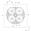
- the optical connector 1 includes a ferrule 10, a plurality of optical fibers 20, an adhesive 30, and two positioning pins 40. Note that the optical connector 1 does not need to include the positioning pins 40.
- the ferrule 10 has a connecting end surface 10a, a rear end surface 10b, an insertion hole 11, an injection hole 12, and two positioning holes 13.
- the connection end surface 10a is a surface that is abutted against another connector or the like when the optical connector 1 is connected to the other connector or the like.
- the insertion hole 11 and the two positioning holes 13 are open to the connection end surface 10a.
- An introduction hole (not shown) communicating with the insertion hole 11 is opened in the rear end surface 10b, and a plurality of optical fibers 20 are introduced into the ferrule 10 through the introduction hole.
- a positioning pin 40 is inserted into each of the two positioning holes 13.
- a direction parallel to the central axis O of the insertion hole 11 is referred to as a Z direction, an axial direction Z, or a longitudinal direction Z.
- One direction perpendicular to the longitudinal direction Z is referred to as a first direction X.
- the first direction X is also the direction in which the two positioning holes 13 are arranged.
- a direction perpendicular to both the longitudinal direction Z and the first direction X is referred to as a second direction Y.
- the direction from the rear end surface 10b of the ferrule 10 toward the connection end surface 10a along the longitudinal direction Z is referred to as the +Z direction, the front, or the tip side.
- the direction opposite to the +Z direction is referred to as the -Z direction, rearward, or proximal side.
- the direction perpendicular to the central axis O when viewed from the longitudinal direction Z is referred to as the radial direction.
- the direction approaching the center axis O is called the radially inner side
- the direction away from the center axis O is called the radially outer side.
- the direction of rotation around the central axis O when viewed from the longitudinal direction Z is referred to as the circumferential direction.
- a cross section perpendicular to the longitudinal direction Z is called a cross section. That is, the cross section is a cross section extending along the first direction X and the second direction Y.
- the insertion hole 11 is arranged so as to be sandwiched between two positioning holes 13.
- the injection hole 12 is open in one end surface of the ferrule 10 facing in the second direction Y.
- the injection hole 12 communicates with the internal space of the ferrule 10 and the insertion hole 11 .
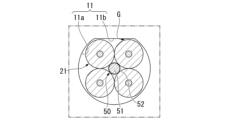
- FIG. 2 is an extracted diagram of the plurality of optical fibers 20 shown in FIG. 1.
- the optical connector 1 of this embodiment has four optical fibers 20.
- the number of optical fibers 20 may be changed.
- Each optical fiber 20 has a bare fiber 21 and a coating 22.
- the bare fiber 21 is made of, for example, quartz glass.
- the covering 22 partially covers the bare fiber 21 and has the role of protecting the bare fiber 21.
- the covering 22 is made of resin or the like.
- the material of the coating 22 may be a UV curable resin.
- the coating 22 is not provided, and the bare fiber 21 is exposed. The exposed bare fiber 21 is inserted into the insertion hole 11 of the ferrule 10.
- the bare fiber 21 has a small diameter portion 21a and a large diameter portion 21b.
- the outer diameter of the small diameter portion 21a is smaller than the outer diameter of the large diameter portion 21b.
- the small diameter portion 21a can be formed by, for example, making the end portion of the bare fiber 21 having a constant outer diameter (the same outer diameter as the large diameter portion 21b) in the longitudinal direction Z thinner by etching. In this embodiment, the small diameter portion 21a is inserted into the insertion hole 11 of the ferrule 10.
- FIG. 3 is a cross-sectional view of the vicinity of the insertion hole 11.
- the bare fiber 21 has a core 21c and a cladding 21d.
- the cladding 21d is arranged to surround the core 21c.
- the refractive index of the cladding 21d is lower than that of the core 21c. Therefore, the optical fiber 20 can confine light inside the core 21c.
- the insertion hole 11 of this embodiment has a curved portion 11a and a straight portion 11b when viewed from the longitudinal direction Z.
- the curved portion 11a has an arc shape. That is, the insertion hole 11 is D-shaped.
- two bare fibers 21 come into contact with both the curved portion 11a and the straight portion 11b.
- the remaining two bare fibers 21 contact the curved portion 11a but do not contact the straight portion 11b.
- the bare fiber 21 and the insertion hole 60 are in contact with each other at six locations. The positions of these four bare fibers 21 are determined by being pressed against the inner surface of the insertion hole 11 by an expansion member 50, which will be described later.
- the adhesive 30 has the function of fixing the plurality of optical fibers 20 to the ferrule 10.
- thermosetting resin can be used. More specifically, the material of the adhesive 30 may be epoxy resin.
- the insertion hole 11 is filled with liquid adhesive 30 through the injection hole 12 with the bare fiber 21 inserted into the insertion hole 11. Then, the adhesive 30 is cured. Here, the adhesive 30 may shrink during curing. When the adhesive 30 contracts, a force directed inward in the radial direction may be applied to the bare fibers 21 . The position of the bare fiber 21 is determined by contacting the inner surface of the insertion hole 11. Therefore, if the bare fiber 21 separates from the inner surface of the insertion hole 11 due to the shrinkage of the adhesive 30, the bare fiber 21 will be displaced from the predetermined position. If the bare fiber 21 is misaligned inside the insertion hole 11, the connection loss of the optical connector 1 will increase.
- the adhesive 30 when an epoxy resin is used as the adhesive 30, heating is performed to harden the adhesive 30.
- the viscosity of the epoxy resin rapidly decreases from 30°C to 50°C, and when the temperature exceeds 50°C, the viscosity of the epoxy resin becomes equal to or lower than that of water.
- the viscosity of the adhesive 30 decreases in this way, the bare fiber 21 easily moves inside the insertion hole 11 and becomes easily separated from the inner surface of the insertion hole 11.
- the optical connector 1 of this embodiment includes an expansion member 50 for pressing the bare fiber 21 against the inner surface of the insertion hole 11, as shown in FIG.
- the expansion member 50 is a linear member extending in the longitudinal direction Z.
- the expansion member 50 is inserted into the insertion hole 11 along with the plurality of bare fibers 21 . Inside the insertion hole 11, the expansion member 50 is in contact with each bare fiber 21 (small diameter portion 21a). Each bare fiber 21 is arranged so as to surround the expansion member 50.
- the expansion member 50 is not shown in FIG. 1, the expansion member 50 may extend rearward from the ferrule 10 together with the plurality of optical fibers 20.
- the expansion member 50 is configured to press the bare fiber 21 against the inner surface of the insertion hole 11.
- the expansion member 50 of this embodiment includes a main body portion 51 and a release layer 52.
- the main body 51 has a linear shape, and the release layer 52 is provided on the surface of the main body 51 .
- the release layer 52 has a function of preventing the main body portion 51 from being fixed to the adhesive 30. The presence of the peeling layer 52 facilitates the operation of removing the expansion member 50 from the optical connector 1, as will be described later.
- the release layer 52 may be formed, for example, by subjecting the main body portion 51 to a surface treatment.
- the release layer 52 may be, for example, a fluorine-based coating agent. Note that the inflatable member 50 does not need to have the release layer 52.
- a preparation process is performed.
- the ferrule 10, the plurality of optical fibers 20, the adhesive 30, the expansion member 50, etc. are prepared.
- the coating 22 at the tip of the optical fiber 20 is removed and the bare fiber 21 is exposed. If necessary, an etching process or the like is performed on the exposed bare fiber 21 to form a small diameter portion 21a. Further, if necessary, surface treatment is performed on the main body portion 51 of the expansion member 50 to form a release layer 52.
- the insertion process is performed.
- the bare fibers 21 of the plurality of optical fibers 20 and the expansion member 50 are inserted into the insertion hole 11 of the ferrule 10.
- the expansion member 50 may be used as an introduction jig for introducing the bare fiber 21 into the insertion hole 11.
- the expansion member 50 is first inserted into the insertion hole 11, and the optical fiber 20 is temporarily fixed to a portion of the expansion member 50 located behind the ferrule 10.
- the bare fiber 21 is introduced into the insertion hole 11 together with the expansion member 50 by pulling the expansion member 50 forward from the ferrule 10 or by pushing the expansion member 50 into the ferrule 10 from behind.
- FIG. 4A is a cross-sectional view showing the state inside the insertion hole 11 after performing the insertion process.
- a gap G between the inner surface of the insertion hole 11 and the bare fiber 21 or between the bare fiber 21 and the expansion member 50.
- the outer diameter of the bare fiber 21 (the outer diameter of the small diameter portion 21a), the outer diameter of the expansion member 50, the shape of the insertion hole 11, etc. may be set so that a gap G is generated during the insertion process.
- fluid adhesive 30 is injected into ferrule 10 through injection hole 12 .
- the adhesive 30 also enters into the insertion hole 11.
- the adhesive 30 may be actively introduced into the insertion hole 11 by suctioning the insertion hole 11 opened on the connection end surface 10a with a vacuum or the like.
- the adhesive 30 may be introduced into the insertion hole 11 by capillary force or the like generated within the insertion hole 11 .
- an expansion step is performed.
- the bare fiber 21 is pressed against the inner surface of the insertion hole 11 by heating the expansion member 50 to a first temperature and expanding the expansion member 50 .
- the first temperature is a temperature lower than the curing temperature of the adhesive.
- the "curing temperature” is the temperature at which the adhesive 30 is sufficiently cured when the adhesive 30 is a thermosetting resin.
- the curing temperature of the adhesive 30 is about 100°C. Therefore, the first temperature in this case is a temperature lower than 100°C (for example, about 50°C).
- the bare fiber 21 is positioned. Note that, since the viscosity of the epoxy resin becomes extremely small near 50°C, if the first temperature is about 50°C, the movement of the bare fiber 21 during the expansion process becomes easy. In other words, the movement of the bare fibers 21 can be prevented from being inhibited by the viscosity of the adhesive 30.
- first bare fibers the two bare fibers 21 located above in the drawing are abutted against both the curved part 11a and the straight part 11b, The position is determined. Furthermore, the two bare fibers 21 (hereinafter sometimes referred to as “second bare fibers”) located at the lower side in the drawing are abutted against both the first bare fiber and the curved portion 11a, and their positions are determined.
- the bare fiber 21 is fixed to the ferrule 10 by curing the adhesive 30.
- the adhesive 30 is a thermosetting resin such as an epoxy resin
- the adhesive 30 is heated to a second temperature that is higher than the curing temperature.
- the adhesive 30 may be cured by a method other than heating.
- the curing step may be performed by irradiating the adhesive 30 with UV light.
- the expansion step and the curing step can be performed continuously.
- the optical connector 1 is heated from room temperature to a first temperature, and in the curing process, the optical connector 1 is heated from the first temperature to a second temperature. These heatings can be performed within the same chamber.
- the connection end surface 10a may be polished to remove portions of the bare fiber 21, adhesive 30, and expansion member 50 that protrude from the insertion hole 11.
- a removal step may be performed.
- the expansion member 50 that has been cooled after being heated contracts. This creates a gap between the adhesive 30 and the expansion member 50.
- the removal step the expansion member 50 is removed from the insertion hole 11. Specifically, the expansion member 50 is pulled forward or backward relative to the ferrule 10.
- the expansible member 50 is provided with the release layer 52, the release layer 52 is easily peeled off from the adhesive 30, so that the removal process can be performed more smoothly.
- FIG. 4C is a cross-sectional view showing the state of the insertion hole 11 after the removal process. When the removal process is performed, a cavity H is formed in the portion where the expansion member 50 was present.
- the bare fiber 21 remains in contact with the inner surface of the insertion hole 11 even after the removal process. In other words, the bare fiber 21 remains positioned. Further, by performing the removal step, for example, the following advantages can be obtained. As a first advantage, it is possible to prevent the expansion member 50 from protruding forward from the connection end surface 10a and inhibiting physical contact between the optical connector 1 and other connectors. As a second advantage, when the expansion member 50 has water absorption properties, it is possible to suppress deterioration of the adhesive 30 due to moisture contained in the expansion member 50. As a third advantage, the weight of the optical connector 1 can be reduced. As a fourth advantage, the formed cavity H can be used for other purposes.
- a light source for illumination may be inserted into the cavity H.
- the adhesive 30 expands due to a temperature change after manufacturing the optical connector 1, the volume of the expanded adhesive 30 can be released into the cavity H. Thereby, the expansion of the adhesive 30 can be suppressed from acting to move the bare fibers 21.
- the cavity H is formed so as to penetrate the adhesive 30 in the longitudinal direction Z.
- the plurality of bare fibers 21 are arranged so as to face the cavity H and surround the cavity H. Note that it is not essential to perform the removal step. That is, the optical connector 1 may or may not include the expansion member 50 in the state after manufacture.
- the expansion member 50 is configured to expand at a temperature lower than the curing temperature of the adhesive 30.
- the material of the main body portion 51 of the expansion member 50 for example, resin, metal, etc. can be adopted. More specifically, the material of the main body portion 51 may be oxetane resin or copper.
- the linear expansion coefficient of the oxetane resin can be changed depending on the formulation, but is, for example, about 90 ⁇ 10 -6 /K at 0 to 50°C, and about 170 ⁇ 10 -6 /K at 50 to 100°C.
- the coefficient of linear expansion of copper is approximately constant between 0 and 100° C., and is approximately 16.8 ⁇ 10 ⁇ 6 /K.
- the glass transition temperature of the main body portion 51 of the expansion member 50 is preferably lower than the glass transition temperature of the adhesive 30.
- the glass transition temperature of epoxy resin is 90°C
- the glass transition temperature of oxetane resin is 50°C to 80°C.
- the linear expansion coefficient of oxetane resin increases rapidly when the glass transition temperature is exceeded.
- the expansion speed of the expansion member 50 increases, and the bare fiber 21 can be quickly pressed against the inner surface of the insertion hole 11. Thereby, the bare fiber 21 can be positioned at an early stage. Note that once the adhesive 30 begins to harden, movement of the bare fiber 21 within the insertion hole 11 is inhibited, so it is preferable to position the bare fiber 21 early.
- the water absorption rate of the expansion member 50 is preferably lower than that of the ferrule 10. Since the water absorption rate of the expansion member 50 is low, deterioration of the adhesive 30 due to moisture contained in the expansion member 50 can be suppressed. Note that, since the volume occupied by the release layer 52 in the inflatable member 50 is very small, the water absorption rate of the inflatable member 50 is substantially the same as the water absorption rate of the main body portion 51. The same applies to other physical properties of the expansion member 50. That is, in this embodiment, the linear expansion coefficient, glass transition temperature, and water absorption rate of the expansion member 50 are substantially the same as the linear expansion coefficient, glass transition temperature, and water absorption rate of the main body portion 51.
- the material of the ferrule 10 is, for example, PPS+GF (polyphenylene sulfide containing 30% to 70% glass fiber).
- the material of the main body portion 51 of the expansion member 50 is, for example, oxetane resin, and the water absorption rate in this case is lower than that of PPS+GF.
- the optical connector 1 of the present embodiment includes a ferrule 10 having an insertion hole 11, a plurality of optical fibers 20 inserted into the insertion hole 11, and a plurality of optical fibers 20 inserted into the insertion hole 11 together with the plurality of optical fibers 20. and an adhesive 30 for fixing the plurality of optical fibers 20 to the ferrule 10 in a state where the plurality of optical fibers 20 and the expansion member 50 are inserted into the insertion hole 11.
- the adhesive 30 is, for example, a thermosetting resin, and the expansion member 50 expands at a temperature lower than the curing temperature of the adhesive 30. With such a configuration, the optical fiber 20 can be pressed against the inner surface of the insertion hole 11 by the expansion member 50. Therefore, it becomes possible to suppress the positional shift of the optical fiber 20 inside the insertion hole 11.
- the expansion member 50 has a larger coefficient of linear expansion than the optical fiber 20 at the curing temperature of the adhesive. This makes it possible to increase the expansion speed of the expansion member 50 and quickly determine the position of the optical fiber 20 within the insertion hole 11.
- the glass transition temperature of the expansion member 50 is preferably lower than that of the adhesive 30. Since the glass transition temperature of the expansion member 50 is low, the linear expansion coefficient of the expansion member 50 increases steeply due to heating. This makes it possible to increase the expansion speed of the expansion member 50 and quickly determine the position of the optical fiber 20 within the insertion hole 11.
- the water absorption rate of the expansion member 50 is smaller than that of the ferrule 10. Since the water absorption rate of the expansion member 50 is small, deterioration of the adhesive 30 can be suppressed.
- the plurality of optical fibers 20 be arranged inside the insertion hole 11 so as to surround the expansion member 50. Furthermore, it is preferable that the expansion member 50 contacts all of the plurality of optical fibers 20 inside the insertion hole 11 . According to this arrangement, when the expansion member 50 expands, a radially outward pressing force acts on each optical fiber 20. Therefore, each optical fiber 20 can be pressed against the inner surface of the insertion hole 11 more reliably.
- the insertion hole 11 has a curved portion 11a and a straight portion 11b in a cross section perpendicular to the central axis O. In this case, by abutting at least a portion of the optical fiber 20 against both the curved portion 11a and the straight portion 11b, the position of the optical fiber 20 can be determined more accurately.
- a release layer 52 may be provided on the surface of the inflatable member 50.
- the expansion member 50 when the adhesive 30 hardens, the expansion member 50 can be prevented from sticking to the adhesive 30 and the optical fiber 20. Therefore, even if the expansion member 50 contracts after the adhesive 30 hardens, the optical fiber 20 can be prevented from moving due to this contraction. Furthermore, it becomes easy to pull out the expansion member 50 from the ferrule 10.
- the method for manufacturing the optical connector 1 includes inserting the expansion member 50 together with the plurality of optical fibers 20 into the insertion hole 11 of the ferrule 10, injecting the adhesive 30 into the insertion hole 11, and inserting the expansion member 50 into the insertion hole 11 of the ferrule 10.
- the plurality of optical fibers 20 are pressed against the inner surface of the insertion hole 11 by the expansion member 50, and the plurality of optical fibers 20 are fixed to the ferrule 10 by curing the adhesive 30. According to such a manufacturing method, it is possible to suppress misalignment of the optical fiber 20 inside the insertion hole 11.
- the expansion member 50 may be removed from the insertion hole 11.
- various advantages can be obtained.
- the optical connector 1 also includes a ferrule 10 having an insertion hole 11, a plurality of optical fibers 20 inserted into the insertion hole 11, and an adhesive 30 for fixing the plurality of optical fibers 20 inside the insertion hole 11.
- a cavity H extending in the longitudinal direction Z of the insertion hole 11 may be formed in the adhesive 30.
- the bare fiber 21 has a small diameter portion 21a and a large diameter portion 21b, and the small diameter portion 21a is inserted into the insertion hole 11 of the ferrule 10.
- the outer diameter of the bare fiber 21 may be constant in the longitudinal direction Z. That is, the tip of the bare fiber 21 may be inserted into the insertion hole 11 as it is without reducing its diameter by etching or the like.
- a plurality of bare fibers 21 are arranged to surround the expansion member 50, and one expansion member 50 is in contact with all the bare fibers 21.
- the arrangement of the bare fiber 21 and the expansion member 50 may be changed.
- two expansion members 50 may be arranged within the insertion hole 11. More specifically, the two expansion members 50 may be arranged apart in the radial direction and may be in contact with the inner surface of the insertion hole 11, respectively. Then, one expansion member 50 may be in contact with two bare fibers 21, and the remaining expansion member 50 may be in contact with the remaining two bare fibers 21. Even with such an arrangement, each bare fiber 21 can be pressed against the inner surface of the insertion hole 11.
- the shape of the insertion hole 11 can be changed.
- the insertion hole 11 may not have the straight portion 11b and may have the entire curved portion 11a. That is, the insertion hole 11 may have a circular shape.
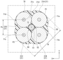
- the insertion hole 11 has a D shape, but the insertion hole 60 may have a rectangular shape as shown in FIG. 6.
- the insertion hole 60 of this modification has four straight portions 61a to 61d and a corner portion 62 when viewed from the longitudinal direction Z.
- the shape of the insertion hole 60 satisfies the following equation (1). Rh ⁇ r...(1)
- the radius of curvature Rh of the corner 62 is smaller than the radius r of the bare fiber 21, so a gap is formed between the corner 62 and the bare fiber 21.
- each of the four bare fibers 21 contacts two straight portions among the straight portions 61a to 61d. Therefore, the four bare fibers 21 come into contact with the insertion hole 60 at eight locations. Further, if the length of one side of the insertion hole 60 is L, and the design value of the distance between the cores 21c of adjacent bare fibers 21 is Pc, the shape of the insertion hole 60 can be calculated using the following equations (2) and (3). Fulfill. L>4r...(2) Pc ⁇ L-2r...(3) The positions of these four bare fibers 21 are determined by being pressed against the inner surface of the insertion hole 60 by the above-described expansion member 50.
- the insertion hole 60 has a rectangular shape, by pressing the bare fiber 21 against the inner surface of the insertion hole 60, which has a simple configuration, the optical fiber 20 inside the insertion hole 60 can be It becomes possible to suppress positional deviation. Further, since the shape of the insertion hole 60 satisfies the above formulas (2) and (3), some gaps are formed between the bare fiber 21 and the straight portions 61a to 61d. Thereby, the four bare fibers 21 can be easily inserted into the insertion hole 60.
- the insertion hole 11 was D-shaped, but as shown in FIG. 7, the insertion hole 70 is composed of four curved parts 71a to 71d when viewed from the longitudinal direction Z. It's okay.
- the shape of the insertion hole 70 satisfies the following equation (4). Rh1>r...(4) From the above equation (4), the radius of curvature Rh1 of the curved portions 71a to 71d is larger than the radius r of the bare fibers 21A to 21D.
- each of the four bare fibers 21A to 21D contacts each of the curved portions 71a to 71d at one point.
- the four bare fibers 21A to 21D come into contact with the insertion hole 70 at four locations.
- the positions of these four bare fibers 21 are determined by being pressed against the inner surface of the insertion hole 70 by the above-mentioned expansion member 50.
- the manufacturing method of the optical connector 1 of the said embodiment may have a suppression process.
- the suppressing step is a step of suppressing the expansion member 50 from protruding from the tip surface 21e of the bare fiber 21, as shown in FIG.
- a pin 80 is used as a jig for holding down the expansion member 50.
- the pin 80 has a tapered portion 81 whose outer diameter gradually decreases toward the distal end surface 80a of the pin 80, and a straight portion 82 that extends toward the proximal end of the pin 80.
- the tip of the tapered portion 81 of the pin 80 has a planar shape.
- the shape of the pin 80 satisfies the following equations (8) and (9). D1 ⁇ W-4r...(8) D2>W-4r...(9)
- the outer diameter D1 of the tip end surface 80a of the pin 80 is smaller than the outer diameter of the expansion member 50. This allows the tip end surface 80a of the pin 80 to contact only the expansion member 50.
- the material of the pin 80 is not particularly limited, but a material with lower hardness than quartz glass may be used.
- the material of the pin 80 is aluminum or plastic.
- the distance between the tip surface 21e of the bare fiber 21 and the tip surface 50a of the expansion member 50 in the longitudinal direction Z is about 1.0 to 3.5 ⁇ m.
- the pin 80 is placed on the distal end surface 50a of the expansion member 50 before the expansion step. Thereafter, the expansion member 50 is heated and expanded. At this time, by holding down the expansion member 50 expanding in the +Z direction with the pin 80, the expansion member 50 expands in the circumferential direction.
- the removal step when the expansion member 50 is cooled, the pin 80 is removed. As a result, the distal end surface 50a of the inflatable member 50 is depressed, and a mark of the distal end surface 80a of the tapered portion 81 remains on the distal end surface 50a of the inflatable member 50.
- the pin 80 can assist in positioning. Furthermore, since the pin 80 is in contact with the bare fiber 21, it is possible to suppress the expansion member 50 from protruding beyond the tip end surface 21e of the bare fiber 21.
- the material of the pin 80 is made of a material with lower hardness than quartz glass, so that even if the pin 80 and the bare fiber 21 come into contact, the expansion member 50 can protrude without damaging the bare fiber 21. It becomes possible to suppress this.
- the expansion member 50 is pushed in the -Z direction from the position of the tip surface 21e of the bare fiber 21 by the pin 80, but the invention is not limited to this. You can also push it in. Note that if the pin 80 does not need to assist in positioning, the pin 80 does not need to have a portion that satisfies the above formula (9). In this configuration, the jig does not come into contact with the bare fiber 21. Therefore, it is possible to suppress the expansion member 50 from protruding while suppressing the possibility of damaging the tip end surface 21e of the polished bare fiber 21.
- the jig may have a constant outer diameter as a whole, or may have a configuration having only a tapered portion where the outer diameter widens toward the proximal end. In the case of this configuration, the jig only needs to satisfy at least the above equation (8) among the above equations (8) and (9). Further, although the tip of the tapered portion 81 of the pin 80 is made into a planar shape, it may be curved.
Abstract
This optical connector comprises: a ferrule having an insertion through-hole (11); a plurality of optical fibers inserted into the insertion through-hole; an expansion member (50) inserted into the insertion through-hole together with the plurality of optical fibers; and an adhesive (30) which fixes the plurality of optical fibers to the ferrule while the plurality of optical fibers and the expansion member are inserted through the insertion through-hole, wherein the adhesive is a thermosetting resin and the expansion member expands at a lower temperature than the curing temperature of the adhesive.
Description
本発明は、光コネクタおよび光コネクタの製造方法に関する。
本願は、2022年8月19日に日本に出願された特願2022-130948号について優先権を主張し、その内容をここに援用する。 The present invention relates to an optical connector and a method of manufacturing the optical connector.
This application claims priority to Japanese Patent Application No. 2022-130948 filed in Japan on August 19, 2022, and the contents thereof are incorporated herein.
特許文献1には、フェルールが有する挿通孔に、複数の光ファイバを挿入した構造が開示されている。挿通孔には、複数の光ファイバをフェルールに固定するための接着剤が充填される。このような構造を有する光コネクタによれば、例えば、複数の光ファイバを、1本のマルチコアファイバに接続することができる。
Patent Document 1 discloses a structure in which a plurality of optical fibers are inserted into an insertion hole of a ferrule. The insertion hole is filled with an adhesive for fixing the plurality of optical fibers to the ferrule. According to an optical connector having such a structure, for example, a plurality of optical fibers can be connected to one multi-core fiber.
フェルールの挿通孔に充填された接着剤は、硬化する際に収縮する場合がある。接着剤が収縮すると、挿通孔の内部における光ファイバの位置がずれてしまい、光コネクタの接続損失の増大につながる可能性がある。
The adhesive filled in the insertion hole of the ferrule may shrink when it hardens. When the adhesive contracts, the position of the optical fiber inside the insertion hole may shift, which may lead to an increase in connection loss of the optical connector.
本発明はこのような事情を考慮してなされ、フェルールの内部における光ファイバの位置ずれを抑制することが可能な光コネクタ、あるいはそのような光コネクタの製造方法を提供することを目的とする。
The present invention has been made in consideration of the above circumstances, and an object of the present invention is to provide an optical connector capable of suppressing misalignment of an optical fiber inside a ferrule, or a method of manufacturing such an optical connector.
上記課題を解決するために、本発明の態様1に係る光コネクタは、挿通孔を有するフェルールと、前記挿通孔に挿通された複数の光ファイバと、前記挿通孔に、前記複数の光ファイバとともに挿通された膨張部材と、前記複数の光ファイバおよび前記膨張部材が前記挿通孔に挿通された状態で、前記複数の光ファイバを前記フェルールに固定する接着剤と、を備え、前記接着剤は熱硬化性樹脂であり、前記膨張部材は、前記接着剤の硬化温度よりも低い温度において膨張する。
In order to solve the above problems, an optical connector according to aspect 1 of the present invention includes: a ferrule having an insertion hole; a plurality of optical fibers inserted into the insertion hole; an adhesive that fixes the plurality of optical fibers to the ferrule in a state in which the plurality of optical fibers and the expansion member are inserted into the insertion hole, the adhesive being heated The adhesive is a curable resin, and the expansion member expands at a temperature lower than the curing temperature of the adhesive.
本発明の態様2は、態様1に係る光コネクタであって、前記膨張部材は、前記接着剤の硬化温度において、前記光ファイバよりも大きい線膨張係数を有していてもよい。
A second aspect of the present invention is the optical connector according to the first aspect, in which the expansion member may have a coefficient of linear expansion larger than that of the optical fiber at the curing temperature of the adhesive.
本発明の態様3は、態様1または2に係る光コネクタであって、前記膨張部材のガラス転移温度は、前記接着剤のガラス転移温度より低くてもよい。
A third aspect of the present invention is the optical connector according to the first or second aspect, in which the expansion member may have a glass transition temperature lower than that of the adhesive.
本発明の態様4は、態様1から3のいずれかに係る光コネクタであって、前記膨張部材の吸水率は、前記フェルールの吸水率より小さくてもよい。
Aspect 4 of the present invention is an optical connector according to any one of aspects 1 to 3, in which the water absorption rate of the expansion member may be lower than the water absorption rate of the ferrule.
本発明の態様5は、態様1から4のいずれかに係る光コネクタであって、前記複数の光ファイバは、前記挿通孔の内部において、前記膨張部材を囲うように配置されていてもよい。
A fifth aspect of the present invention is the optical connector according to any one of aspects 1 to 4, in which the plurality of optical fibers may be arranged inside the insertion hole so as to surround the expansion member.
本発明の態様6は、態様1から5のいずれかに係る光コネクタであって、前記膨張部材は、前記挿通孔の内部において、前記複数の光ファイバの全てに接触してもよい。
A sixth aspect of the present invention is the optical connector according to any one of aspects 1 to 5, in which the expansion member may contact all of the plurality of optical fibers inside the insertion hole.
本発明の態様7は、態様1から6のいずれかに係る光コネクタであって、前記挿通孔は、前記挿通孔の中心軸線に直交する横断面において、湾曲部および直線部を有していてもよい。
A seventh aspect of the present invention is the optical connector according to any one of aspects 1 to 6, wherein the insertion hole has a curved portion and a straight portion in a cross section perpendicular to the central axis of the insertion hole. Good too.
本発明の態様8は、態様1から7のいずれかに係る光コネクタであって、前記膨張部材の表面に剥離層が設けられていてもよい。
Aspect 8 of the present invention is an optical connector according to any one of aspects 1 to 7, in which a release layer may be provided on the surface of the expansion member.
本発明の態様9は、フェルールの挿通孔に、複数の光ファイバとともに膨張部材を挿通し、前記挿通孔に接着剤を注入し、前記膨張部材を加熱して膨張させることで、前記膨張部材によって前記複数の光ファイバを前記挿通孔の内面に押し付け、前記接着剤を硬化させることで、前記複数の光ファイバを前記フェルールに固定する、光コネクタの製造方法である。
A ninth aspect of the present invention is that an expansion member is inserted into an insertion hole of a ferrule together with a plurality of optical fibers, an adhesive is injected into the insertion hole, and the expansion member is heated and expanded. The method of manufacturing an optical connector includes fixing the plurality of optical fibers to the ferrule by pressing the plurality of optical fibers against the inner surface of the insertion hole and curing the adhesive.
本発明の態様10は、態様9に係る光コネクタの製造方法であって、前記接着剤によって前記複数の光ファイバを前記フェルールに固定した後、前記膨張部材を前記挿通孔から除去してもよい。
A tenth aspect of the present invention is the method for manufacturing the optical connector according to aspect nine, in which the expansion member may be removed from the insertion hole after the plurality of optical fibers are fixed to the ferrule with the adhesive. .
本発明の上記態様によれば、フェルールの内部における光ファイバの位置ずれを抑制することが可能な光コネクタ、あるいはそのような光コネクタの製造方法を提供できる。
According to the above aspects of the present invention, it is possible to provide an optical connector capable of suppressing misalignment of an optical fiber inside a ferrule, or a method for manufacturing such an optical connector.
以下、本実施形態の光コネクタについて図面に基づいて説明する。
図1に示すように、光コネクタ1は、フェルール10と、複数の光ファイバ20と、接着剤30と、2つの位置決めピン40と、を備える。なお、光コネクタ1は位置決めピン40を備えていなくてもよい。 Hereinafter, the optical connector of this embodiment will be explained based on the drawings.
As shown in FIG. 1, the optical connector 1 includes aferrule 10, a plurality of optical fibers 20, an adhesive 30, and two positioning pins 40. Note that the optical connector 1 does not need to include the positioning pins 40.
図1に示すように、光コネクタ1は、フェルール10と、複数の光ファイバ20と、接着剤30と、2つの位置決めピン40と、を備える。なお、光コネクタ1は位置決めピン40を備えていなくてもよい。 Hereinafter, the optical connector of this embodiment will be explained based on the drawings.
As shown in FIG. 1, the optical connector 1 includes a
フェルール10は、接続端面10aと、後端面10bと、挿通孔11と、注入孔12と、2つの位置決め孔13と、を有している。接続端面10aは、光コネクタ1が他のコネクタ等に接続される際に、他のコネクタ等に突き当てられる面である。挿通孔11および2つの位置決め孔13は、接続端面10aに開口している。後端面10bには、挿通孔11と連通する不図示の導入孔が開口しており、その導入孔を通して、複数の光ファイバ20がフェルール10内に導入されている。2つの位置決め孔13にはそれぞれ、位置決めピン40が挿通されている。
The ferrule 10 has a connecting end surface 10a, a rear end surface 10b, an insertion hole 11, an injection hole 12, and two positioning holes 13. The connection end surface 10a is a surface that is abutted against another connector or the like when the optical connector 1 is connected to the other connector or the like. The insertion hole 11 and the two positioning holes 13 are open to the connection end surface 10a. An introduction hole (not shown) communicating with the insertion hole 11 is opened in the rear end surface 10b, and a plurality of optical fibers 20 are introduced into the ferrule 10 through the introduction hole. A positioning pin 40 is inserted into each of the two positioning holes 13.
(方向定義)
本明細書では、挿通孔11の中心軸線Oと平行な方向を、Z方向、軸方向Z、または長手方向Zと称する。長手方向Zに直交する一方向を、第1方向Xと称する。第1方向Xは、2つの位置決め孔13が並べられた方向でもある。長手方向Zおよび第1方向Xの双方に直交する方向を、第2方向Yと称する。長手方向Zに沿って、フェルール10の後端面10bから接続端面10aに向かう向きを、+Zの向き、前方、または先端側と称する。+Zの向きとは反対の向きを、-Zの向き、後方、または基端側と称する。長手方向Zから見て、中心軸線Oに直交する方向を、径方向と称する。径方向に沿って、中心軸線Oに接近する向きを、径方向内側と称し、中心軸線Oから離反する向きを、径方向外側と称する。長手方向Zから見て、中心軸線Oまわりに周回する方向を、周方向と称する。長手方向Zに直交する断面を横断面と称する。すなわち横断面とは、第1方向Xおよび第2方向Yに沿って延在する断面である。 (direction definition)
In this specification, a direction parallel to the central axis O of theinsertion hole 11 is referred to as a Z direction, an axial direction Z, or a longitudinal direction Z. One direction perpendicular to the longitudinal direction Z is referred to as a first direction X. The first direction X is also the direction in which the two positioning holes 13 are arranged. A direction perpendicular to both the longitudinal direction Z and the first direction X is referred to as a second direction Y. The direction from the rear end surface 10b of the ferrule 10 toward the connection end surface 10a along the longitudinal direction Z is referred to as the +Z direction, the front, or the tip side. The direction opposite to the +Z direction is referred to as the -Z direction, rearward, or proximal side. The direction perpendicular to the central axis O when viewed from the longitudinal direction Z is referred to as the radial direction. Along the radial direction, the direction approaching the center axis O is called the radially inner side, and the direction away from the center axis O is called the radially outer side. The direction of rotation around the central axis O when viewed from the longitudinal direction Z is referred to as the circumferential direction. A cross section perpendicular to the longitudinal direction Z is called a cross section. That is, the cross section is a cross section extending along the first direction X and the second direction Y.
本明細書では、挿通孔11の中心軸線Oと平行な方向を、Z方向、軸方向Z、または長手方向Zと称する。長手方向Zに直交する一方向を、第1方向Xと称する。第1方向Xは、2つの位置決め孔13が並べられた方向でもある。長手方向Zおよび第1方向Xの双方に直交する方向を、第2方向Yと称する。長手方向Zに沿って、フェルール10の後端面10bから接続端面10aに向かう向きを、+Zの向き、前方、または先端側と称する。+Zの向きとは反対の向きを、-Zの向き、後方、または基端側と称する。長手方向Zから見て、中心軸線Oに直交する方向を、径方向と称する。径方向に沿って、中心軸線Oに接近する向きを、径方向内側と称し、中心軸線Oから離反する向きを、径方向外側と称する。長手方向Zから見て、中心軸線Oまわりに周回する方向を、周方向と称する。長手方向Zに直交する断面を横断面と称する。すなわち横断面とは、第1方向Xおよび第2方向Yに沿って延在する断面である。 (direction definition)
In this specification, a direction parallel to the central axis O of the
接続端面10aにおいて、挿通孔11は、2つの位置決め孔13に挟まれるように配置されている。注入孔12は、フェルール10が有する、第2方向Yを向く1つの端面に開口している。注入孔12は、フェルール10の内部空間および挿通孔11に連通している。光コネクタ1が組み立てられる際、注入孔12を通して、接着剤30がフェルール10内に注入される。注入された接着剤30は、挿通孔11の内部にも進入する。
In the connection end surface 10a, the insertion hole 11 is arranged so as to be sandwiched between two positioning holes 13. The injection hole 12 is open in one end surface of the ferrule 10 facing in the second direction Y. The injection hole 12 communicates with the internal space of the ferrule 10 and the insertion hole 11 . When the optical connector 1 is assembled, the adhesive 30 is injected into the ferrule 10 through the injection hole 12. The injected adhesive 30 also enters the inside of the insertion hole 11 .
図2は、図1に示す複数の光ファイバ20を抜き出した図である。図2に示すように、本実施形態の光コネクタ1は、4本の光ファイバ20を有している。ただし、光ファイバ20の数は変更してもよい。各光ファイバ20は、ベアファイバ21と、被覆22と、を有している。ベアファイバ21は、例えば石英ガラス等によって形成されている。被覆22は、ベアファイバ21を部分的に覆っており、ベアファイバ21を保護する役割を有する。被覆22は、樹脂等によって形成されている。例えば、被覆22の材質はUV硬化型樹脂であってもよい。各光ファイバ20の前方の端部では、被覆22が設けられておらず、ベアファイバ21が露出している。露出したベアファイバ21が、フェルール10の挿通孔11に挿通されている。
FIG. 2 is an extracted diagram of the plurality of optical fibers 20 shown in FIG. 1. As shown in FIG. 2, the optical connector 1 of this embodiment has four optical fibers 20. However, the number of optical fibers 20 may be changed. Each optical fiber 20 has a bare fiber 21 and a coating 22. The bare fiber 21 is made of, for example, quartz glass. The covering 22 partially covers the bare fiber 21 and has the role of protecting the bare fiber 21. The covering 22 is made of resin or the like. For example, the material of the coating 22 may be a UV curable resin. At the front end of each optical fiber 20, the coating 22 is not provided, and the bare fiber 21 is exposed. The exposed bare fiber 21 is inserted into the insertion hole 11 of the ferrule 10.
ベアファイバ21は、小径部21aと、大径部21bと、を有している。小径部21aの外径は大径部21bの外径よりも小さい。小径部21aは、長手方向Zにおいて一定の外径(大径部21bと同じ外径)を有するベアファイバ21の端部を、例えば、エッチングによって細くすることで形成できる。本実施形態では、小径部21aがフェルール10の挿通孔11に挿通されている。
The bare fiber 21 has a small diameter portion 21a and a large diameter portion 21b. The outer diameter of the small diameter portion 21a is smaller than the outer diameter of the large diameter portion 21b. The small diameter portion 21a can be formed by, for example, making the end portion of the bare fiber 21 having a constant outer diameter (the same outer diameter as the large diameter portion 21b) in the longitudinal direction Z thinner by etching. In this embodiment, the small diameter portion 21a is inserted into the insertion hole 11 of the ferrule 10.
図3は、挿通孔11の近傍の横断面図である。図3に示すように、ベアファイバ21は、コア21cおよびクラッド21dを有している。クラッド21dはコア21cを囲むように配置される。クラッド21dの屈折率はコア21cの屈折率よりも低い。このため、光ファイバ20はコア21cの内部に光を閉じ込めることができる。
FIG. 3 is a cross-sectional view of the vicinity of the insertion hole 11. As shown in FIG. 3, the bare fiber 21 has a core 21c and a cladding 21d. The cladding 21d is arranged to surround the core 21c. The refractive index of the cladding 21d is lower than that of the core 21c. Therefore, the optical fiber 20 can confine light inside the core 21c.
図3に示すように、本実施形態の挿通孔11は、長手方向Zから見て、湾曲部11aおよび直線部11bを有している。湾曲部11aは円弧形状を有する。すなわち、挿通孔11はD字状である。4本のベアファイバ21のうち、2本のベアファイバ21は、湾曲部11aおよび直線部11bの双方に当接する。残り2本のベアファイバ21は、湾曲部11aには当接するが、直線部11bには当接しない。この構成により、ベアファイバ21と挿通孔60とは6箇所で接触している。これら4本のベアファイバ21は、後述の膨張部材50によって挿通孔11の内面に押し付けられることで、位置が決められる。
As shown in FIG. 3, the insertion hole 11 of this embodiment has a curved portion 11a and a straight portion 11b when viewed from the longitudinal direction Z. The curved portion 11a has an arc shape. That is, the insertion hole 11 is D-shaped. Of the four bare fibers 21, two bare fibers 21 come into contact with both the curved portion 11a and the straight portion 11b. The remaining two bare fibers 21 contact the curved portion 11a but do not contact the straight portion 11b. With this configuration, the bare fiber 21 and the insertion hole 60 are in contact with each other at six locations. The positions of these four bare fibers 21 are determined by being pressed against the inner surface of the insertion hole 11 by an expansion member 50, which will be described later.
接着剤30は、複数の光ファイバ20をフェルール10に固定する機能を有する。接着剤30の材質としては、例えば熱硬化性樹脂を用いることができる。より具体的には、接着剤30の材質はエポキシ樹脂であってもよい。
The adhesive 30 has the function of fixing the plurality of optical fibers 20 to the ferrule 10. As the material of the adhesive 30, for example, thermosetting resin can be used. More specifically, the material of the adhesive 30 may be epoxy resin.
光コネクタ1の製造時には、挿通孔11にベアファイバ21が挿通された状態で、液状の接着剤30が、注入孔12を通して挿通孔11に充填される。そして、接着剤30が硬化される。ここで接着剤30は、硬化の際に収縮する場合がある。接着剤30が収縮すると、ベアファイバ21には、径方向内側に向けた力が作用する可能性がある。ベアファイバ21の位置は、挿通孔11の内面に当接することで決まる。このため、接着剤30の収縮に伴ってベアファイバ21が挿通孔11の内面から離れてしまうと、ベアファイバ21が所定の位置からずれてしまう。挿通孔11の内部におけるベアファイバ21の位置がずれると、光コネクタ1の接続損失の増大につながる。
When manufacturing the optical connector 1, the insertion hole 11 is filled with liquid adhesive 30 through the injection hole 12 with the bare fiber 21 inserted into the insertion hole 11. Then, the adhesive 30 is cured. Here, the adhesive 30 may shrink during curing. When the adhesive 30 contracts, a force directed inward in the radial direction may be applied to the bare fibers 21 . The position of the bare fiber 21 is determined by contacting the inner surface of the insertion hole 11. Therefore, if the bare fiber 21 separates from the inner surface of the insertion hole 11 due to the shrinkage of the adhesive 30, the bare fiber 21 will be displaced from the predetermined position. If the bare fiber 21 is misaligned inside the insertion hole 11, the connection loss of the optical connector 1 will increase.
特に、接着剤30としてエポキシ樹脂を用いた場合には、接着剤30を硬化させるために加熱が行われる。エポキシ樹脂の粘度は30℃~50℃にかけて急激に低下し、50℃を超えると、エポキシ樹脂の粘度は水と同等以下となる。このように接着剤30の粘度が低下すると、挿通孔11の内部でベアファイバ21が容易に移動し、挿通孔11の内面から離れやすくなる。
In particular, when an epoxy resin is used as the adhesive 30, heating is performed to harden the adhesive 30. The viscosity of the epoxy resin rapidly decreases from 30°C to 50°C, and when the temperature exceeds 50°C, the viscosity of the epoxy resin becomes equal to or lower than that of water. When the viscosity of the adhesive 30 decreases in this way, the bare fiber 21 easily moves inside the insertion hole 11 and becomes easily separated from the inner surface of the insertion hole 11.
そこで本実施形態の光コネクタ1は、図3に示すように、ベアファイバ21を挿通孔11の内面に押し付けるための膨張部材50を有している。膨張部材50は、長手方向Zに延びる線状の部材である。膨張部材50は、複数のベアファイバ21とともに、挿通孔11に挿通されている。挿通孔11の内部において、膨張部材50は各ベアファイバ21(小径部21a)に接している。各ベアファイバ21は、膨張部材50を囲うように配置されている。図1では膨張部材50の図示を省略しているが、膨張部材50は、複数の光ファイバ20とともに、フェルール10から後方に延出していてもよい。
Therefore, the optical connector 1 of this embodiment includes an expansion member 50 for pressing the bare fiber 21 against the inner surface of the insertion hole 11, as shown in FIG. The expansion member 50 is a linear member extending in the longitudinal direction Z. The expansion member 50 is inserted into the insertion hole 11 along with the plurality of bare fibers 21 . Inside the insertion hole 11, the expansion member 50 is in contact with each bare fiber 21 (small diameter portion 21a). Each bare fiber 21 is arranged so as to surround the expansion member 50. Although the expansion member 50 is not shown in FIG. 1, the expansion member 50 may extend rearward from the ferrule 10 together with the plurality of optical fibers 20.
膨張部材50は、ベアファイバ21を挿通孔11の内面に押し付けるように構成されている。本実施形態の膨張部材50は、本体部51と、剥離層52と、を有している。本体部51は線状であり、剥離層52は本体部51の表面に設けられている。剥離層52は、本体部51が接着剤30に固着されることを防ぐ機能を有する。剥離層52があることで、後述するように、光コネクタ1から膨張部材50を抜き取る作業が容易となる。剥離層52は、例えば本体部51に表面処理を施すことで形成してもよい。剥離層52は、例えばフッ素系のコーティング剤であってもよい。なお、膨張部材50は剥離層52を有していなくてもよい。
The expansion member 50 is configured to press the bare fiber 21 against the inner surface of the insertion hole 11. The expansion member 50 of this embodiment includes a main body portion 51 and a release layer 52. The main body 51 has a linear shape, and the release layer 52 is provided on the surface of the main body 51 . The release layer 52 has a function of preventing the main body portion 51 from being fixed to the adhesive 30. The presence of the peeling layer 52 facilitates the operation of removing the expansion member 50 from the optical connector 1, as will be described later. The release layer 52 may be formed, for example, by subjecting the main body portion 51 to a surface treatment. The release layer 52 may be, for example, a fluorine-based coating agent. Note that the inflatable member 50 does not need to have the release layer 52.
以下、光コネクタ1の製造方法の一例について説明する。
Hereinafter, an example of a method for manufacturing the optical connector 1 will be described.
まず、準備工程が行われる。準備工程では、フェルール10、複数の光ファイバ20、接着剤30、膨張部材50等が準備される。準備工程において、光ファイバ20の先端部における被覆22が除去され、ベアファイバ21が露出される。必要に応じて、露出したベアファイバ21に対してエッチング処理等を行い、小径部21aを形成する。また、必要に応じて、膨張部材50の本体部51に対して表面処理を行い、剥離層52を形成する。
First, a preparation process is performed. In the preparation step, the ferrule 10, the plurality of optical fibers 20, the adhesive 30, the expansion member 50, etc. are prepared. In the preparation process, the coating 22 at the tip of the optical fiber 20 is removed and the bare fiber 21 is exposed. If necessary, an etching process or the like is performed on the exposed bare fiber 21 to form a small diameter portion 21a. Further, if necessary, surface treatment is performed on the main body portion 51 of the expansion member 50 to form a release layer 52.
次に、挿通工程が行われる。挿通工程では、複数の光ファイバ20のベアファイバ21および膨張部材50が、フェルール10の挿通孔11に挿通される。挿通工程では、膨張部材50を、ベアファイバ21を挿通孔11に導入するための導入治具として用いてもよい。具体的には、先に膨張部材50を挿通孔11に挿通しておき、この膨張部材50のうちフェルール10の後方に位置する部分に、光ファイバ20を仮固定する。その状態で、膨張部材50をフェルール10から前方に牽引すること、あるいは膨張部材50をフェルール10に後方から押し込むことで、ベアファイバ21が膨張部材50とともに挿通孔11に導入される。
Next, the insertion process is performed. In the insertion step, the bare fibers 21 of the plurality of optical fibers 20 and the expansion member 50 are inserted into the insertion hole 11 of the ferrule 10. In the insertion step, the expansion member 50 may be used as an introduction jig for introducing the bare fiber 21 into the insertion hole 11. Specifically, the expansion member 50 is first inserted into the insertion hole 11, and the optical fiber 20 is temporarily fixed to a portion of the expansion member 50 located behind the ferrule 10. In this state, the bare fiber 21 is introduced into the insertion hole 11 together with the expansion member 50 by pulling the expansion member 50 forward from the ferrule 10 or by pushing the expansion member 50 into the ferrule 10 from behind.
図4Aは、挿通工程を行った後の挿通孔11内の状態を示す横断面図である。図4Aに示すように、挿通工程の段階では、挿通孔11の内面とベアファイバ21との間、あるいはベアファイバ21と膨張部材50との間に、隙間Gがあってもよい。このような隙間を設けることで、ベアファイバ21を円滑に挿通孔11に挿通することができる。
ベアファイバ21の外径(小径部21aの外径)、膨張部材50の外径、あるいは挿通孔11の形状等は、挿通工程を行う際に隙間Gが生じるように設定されるとよい。 FIG. 4A is a cross-sectional view showing the state inside theinsertion hole 11 after performing the insertion process. As shown in FIG. 4A, at the stage of the insertion process, there may be a gap G between the inner surface of the insertion hole 11 and the bare fiber 21 or between the bare fiber 21 and the expansion member 50. By providing such a gap, the bare fiber 21 can be smoothly inserted into the insertion hole 11.
The outer diameter of the bare fiber 21 (the outer diameter of thesmall diameter portion 21a), the outer diameter of the expansion member 50, the shape of the insertion hole 11, etc. may be set so that a gap G is generated during the insertion process.
ベアファイバ21の外径(小径部21aの外径)、膨張部材50の外径、あるいは挿通孔11の形状等は、挿通工程を行う際に隙間Gが生じるように設定されるとよい。 FIG. 4A is a cross-sectional view showing the state inside the
The outer diameter of the bare fiber 21 (the outer diameter of the
次に、注入工程が行われる。注入工程では、注入孔12を通して、流動性を有する状態の接着剤30を、フェルール10内に注入する。このとき、接着剤30は挿通孔11内にも入り込む。接続端面10a上に開口する挿通孔11をバキューム等で吸引することで、接着剤30を積極的に挿通孔11内に進入させてもよい。あるいは、挿通孔11内で生じる毛管力等によって、接着剤30を挿通孔11内に進入させてもよい。
Next, an injection process is performed. In the injection step, fluid adhesive 30 is injected into ferrule 10 through injection hole 12 . At this time, the adhesive 30 also enters into the insertion hole 11. The adhesive 30 may be actively introduced into the insertion hole 11 by suctioning the insertion hole 11 opened on the connection end surface 10a with a vacuum or the like. Alternatively, the adhesive 30 may be introduced into the insertion hole 11 by capillary force or the like generated within the insertion hole 11 .
次に、膨張工程が行われる。膨張工程では、第1温度まで膨張部材50を加熱し、膨張部材50を膨張させることで、ベアファイバ21を挿通孔11の内面に押し付ける。第1温度は、接着剤の硬化温度よりも低い温度である。「硬化温度」とは、接着剤30が熱硬化性樹脂である場合に、接着剤30が充分に硬化する温度である。例えば、接着剤30がエポキシ樹脂である場合、接着剤30(エポキシ樹脂)の硬化温度は約100℃である。
したがって、この場合の第1温度は100℃より低い温度(例えば約50℃)である。膨張工程により、図4Bに示すようにベアファイバ21が挿通孔11の内面に押し付けられ、隙間Gが無くなる。これにより、ベアファイバ21が位置決めされる。なお、エポキシ樹脂の粘度は50℃付近でごく小さくなるため、第1温度を約50℃とすると、膨張工程におけるベアファイバ21の移動が容易となる。つまり、接着剤30の粘性によってベアファイバ21の移動が阻害されることを回避できる。 Next, an expansion step is performed. In the expansion step, thebare fiber 21 is pressed against the inner surface of the insertion hole 11 by heating the expansion member 50 to a first temperature and expanding the expansion member 50 . The first temperature is a temperature lower than the curing temperature of the adhesive. The "curing temperature" is the temperature at which the adhesive 30 is sufficiently cured when the adhesive 30 is a thermosetting resin. For example, when the adhesive 30 is an epoxy resin, the curing temperature of the adhesive 30 (epoxy resin) is about 100°C.
Therefore, the first temperature in this case is a temperature lower than 100°C (for example, about 50°C). By the expansion process, thebare fiber 21 is pressed against the inner surface of the insertion hole 11, as shown in FIG. 4B, and the gap G disappears. Thereby, the bare fiber 21 is positioned. Note that, since the viscosity of the epoxy resin becomes extremely small near 50°C, if the first temperature is about 50°C, the movement of the bare fiber 21 during the expansion process becomes easy. In other words, the movement of the bare fibers 21 can be prevented from being inhibited by the viscosity of the adhesive 30.
したがって、この場合の第1温度は100℃より低い温度(例えば約50℃)である。膨張工程により、図4Bに示すようにベアファイバ21が挿通孔11の内面に押し付けられ、隙間Gが無くなる。これにより、ベアファイバ21が位置決めされる。なお、エポキシ樹脂の粘度は50℃付近でごく小さくなるため、第1温度を約50℃とすると、膨張工程におけるベアファイバ21の移動が容易となる。つまり、接着剤30の粘性によってベアファイバ21の移動が阻害されることを回避できる。 Next, an expansion step is performed. In the expansion step, the
Therefore, the first temperature in this case is a temperature lower than 100°C (for example, about 50°C). By the expansion process, the
図4Bに示す例では、図面における上方に位置する2つのベアファイバ21(以下、「第1ベアファイバ」と称する場合がある)が、湾曲部11aおよび直線部11bの双方に突き当てられて、位置が決まる。また、図面における下方に位置する2つのベアファイバ21(以下、「第2ベアファイバ」と称する場合がある)が、第1ベアファイバおよび湾曲部11aの双方に突き当てられて、位置が決まる。
In the example shown in FIG. 4B, the two bare fibers 21 (hereinafter sometimes referred to as "first bare fibers") located above in the drawing are abutted against both the curved part 11a and the straight part 11b, The position is determined. Furthermore, the two bare fibers 21 (hereinafter sometimes referred to as "second bare fibers") located at the lower side in the drawing are abutted against both the first bare fiber and the curved portion 11a, and their positions are determined.
次に、硬化工程が行われる。硬化工程では、接着剤30を硬化させることで、ベアファイバ21をフェルール10に固定する。例えば、接着剤30がエポキシ樹脂等の熱硬化性樹脂である場合には、硬化温度以上である第2温度まで、接着剤30を加熱する。なお、接着剤30が熱硬化性樹脂ではない場合に、加熱以外の方法によって接着剤30を硬化させてもよい。例えば、接着剤30がUV硬化型樹脂である場合に、接着剤30にUV光を照射することで硬化工程を行ってもよい。
Next, a curing process is performed. In the curing process, the bare fiber 21 is fixed to the ferrule 10 by curing the adhesive 30. For example, when the adhesive 30 is a thermosetting resin such as an epoxy resin, the adhesive 30 is heated to a second temperature that is higher than the curing temperature. Note that when the adhesive 30 is not a thermosetting resin, the adhesive 30 may be cured by a method other than heating. For example, when the adhesive 30 is a UV curable resin, the curing step may be performed by irradiating the adhesive 30 with UV light.
接着剤30が熱硬化性樹脂である場合、膨張工程および硬化工程を連続して行うことができる。例えば、膨張工程では光コネクタ1を常温から第1温度まで加熱し、硬化工程では光コネクタ1を第1温度から第2温度まで加熱する。これらの加熱は、同一のチャンバー内で行うことが可能である。硬化工程において加熱を行った場合は、その後で光コネクタ1を冷却する。必要に応じて、接続端面10aを研磨し、ベアファイバ21、接着剤30、および膨張部材50のうち挿通孔11から突出した部分を除去してもよい。
When the adhesive 30 is a thermosetting resin, the expansion step and the curing step can be performed continuously. For example, in the expansion process, the optical connector 1 is heated from room temperature to a first temperature, and in the curing process, the optical connector 1 is heated from the first temperature to a second temperature. These heatings can be performed within the same chamber. When heating is performed in the curing process, the optical connector 1 is cooled afterwards. If necessary, the connection end surface 10a may be polished to remove portions of the bare fiber 21, adhesive 30, and expansion member 50 that protrude from the insertion hole 11.
次に、除去工程が行われてもよい。上述の通り、加熱後に冷却された膨張部材50は収縮する。これにより、接着剤30と膨張部材50との間には、隙間ができる。除去工程では、挿通孔11から膨張部材50を除去する。具体的には、膨張部材50をフェルール10に対して前方または後方に引き抜く。膨張部材50に剥離層52が設けられている場合、剥離層52が接着剤30に対して容易に剥離するため、除去工程をより円滑に行うことができる。図4Cは、除去工程を行った後の挿通孔11の状態を示す横断面図である。除去工程を行った場合、膨張部材50が存在していた部分に空洞Hが形成される。
Next, a removal step may be performed. As described above, the expansion member 50 that has been cooled after being heated contracts. This creates a gap between the adhesive 30 and the expansion member 50. In the removal step, the expansion member 50 is removed from the insertion hole 11. Specifically, the expansion member 50 is pulled forward or backward relative to the ferrule 10. When the expansible member 50 is provided with the release layer 52, the release layer 52 is easily peeled off from the adhesive 30, so that the removal process can be performed more smoothly. FIG. 4C is a cross-sectional view showing the state of the insertion hole 11 after the removal process. When the removal process is performed, a cavity H is formed in the portion where the expansion member 50 was present.
接着剤30は既に硬化しているため、除去工程を行った後も、ベアファイバ21が挿通孔11の内面に接した状態は維持される。つまり、ベアファイバ21が位置決めされた状態が維持される。また、除去工程を行うことで、例えば以下の利点が得られる。第1の利点として、膨張部材50が接続端面10aから前方に突出してしまい、光コネクタ1と他のコネクタとの物理的接触を阻害することを抑制できる。第2の利点として、膨張部材50が吸水性を有する場合に、膨張部材50が含んだ水分によって接着剤30が劣化することを抑制できる。第3の利点として、光コネクタ1を軽量化することができる。第4の利点として、形成された空洞Hを他の用途に転用することができる。例えば、光コネクタ1の製造後の検査において、空洞Hに照明用の光源を挿入してもよい。第5の利点として、光コネクタ1の製造後、温度変化によって接着剤30が膨張した場合に、膨張した接着剤30の体積を空洞Hに逃がすことができる。これにより、接着剤30の膨張がベアファイバ21を移動させるように作用することを抑制できる。
Since the adhesive 30 has already hardened, the bare fiber 21 remains in contact with the inner surface of the insertion hole 11 even after the removal process. In other words, the bare fiber 21 remains positioned. Further, by performing the removal step, for example, the following advantages can be obtained. As a first advantage, it is possible to prevent the expansion member 50 from protruding forward from the connection end surface 10a and inhibiting physical contact between the optical connector 1 and other connectors. As a second advantage, when the expansion member 50 has water absorption properties, it is possible to suppress deterioration of the adhesive 30 due to moisture contained in the expansion member 50. As a third advantage, the weight of the optical connector 1 can be reduced. As a fourth advantage, the formed cavity H can be used for other purposes. For example, in the inspection after manufacturing the optical connector 1, a light source for illumination may be inserted into the cavity H. As a fifth advantage, when the adhesive 30 expands due to a temperature change after manufacturing the optical connector 1, the volume of the expanded adhesive 30 can be released into the cavity H. Thereby, the expansion of the adhesive 30 can be suppressed from acting to move the bare fibers 21.
除去工程を行った場合、空洞Hは、接着剤30を長手方向Zにおいて貫通するように形成される。また、図4Cの例では、複数のベアファイバ21は、空洞Hに面するとともに、空洞Hを囲うように配置される。
なお、除去工程を行うことは必須ではない。つまり、光コネクタ1は、製造後の状態において、膨張部材50を備えてもよいし、膨張部材50を備えていなくてもよい。 When the removal process is performed, the cavity H is formed so as to penetrate the adhesive 30 in the longitudinal direction Z. Moreover, in the example of FIG. 4C, the plurality ofbare fibers 21 are arranged so as to face the cavity H and surround the cavity H.
Note that it is not essential to perform the removal step. That is, the optical connector 1 may or may not include theexpansion member 50 in the state after manufacture.
なお、除去工程を行うことは必須ではない。つまり、光コネクタ1は、製造後の状態において、膨張部材50を備えてもよいし、膨張部材50を備えていなくてもよい。 When the removal process is performed, the cavity H is formed so as to penetrate the adhesive 30 in the longitudinal direction Z. Moreover, in the example of FIG. 4C, the plurality of
Note that it is not essential to perform the removal step. That is, the optical connector 1 may or may not include the
上記の機能を発揮するため、膨張部材50は、接着剤30の硬化温度よりも低い温度において膨張するように構成される。膨張部材50の本体部51の材質としては、例えば樹脂、金属等を採用できる。より具体的には、本体部51の材質はオキセタン樹脂(Oxetane Resin)または銅であってもよい。オキセタン樹脂の線膨張係数は、配合によって変更できるが、例えば0~50℃において約90×10-6/Kであり、50~100℃において約170×10-6/Kである。銅の線膨張係数は、0~100℃において略一定であり、約16.8×10-6/Kである。本体部51として金属を採用した場合、挿入工程において、ベアファイバ21の表面の電荷を本体部51を通じて逃がし、帯電によるベアファイバ21の浮きを抑制する効果が得られる。
In order to perform the above function, the expansion member 50 is configured to expand at a temperature lower than the curing temperature of the adhesive 30. As the material of the main body portion 51 of the expansion member 50, for example, resin, metal, etc. can be adopted. More specifically, the material of the main body portion 51 may be oxetane resin or copper. The linear expansion coefficient of the oxetane resin can be changed depending on the formulation, but is, for example, about 90×10 -6 /K at 0 to 50°C, and about 170×10 -6 /K at 50 to 100°C. The coefficient of linear expansion of copper is approximately constant between 0 and 100° C., and is approximately 16.8×10 −6 /K. When metal is used as the main body part 51, the electric charge on the surface of the bare fiber 21 is released through the main body part 51 during the insertion process, and the effect of suppressing the lifting of the bare fiber 21 due to charging can be obtained.
膨張部材50の本体部51のガラス転移温度は、接着剤30のガラス転移温度よりも低いことが好ましい。例えば、エポキシ樹脂のガラス転移温度は90℃であり、オキセタン樹脂のガラス転移温度は50℃~80℃である。オキセタン樹脂の線膨張係数は、ガラス転移温度を超えると、急激に上昇する。本体部51の線膨張係数が上昇することで、膨張部材50の膨張スピードが上昇し、速やかにベアファイバ21を挿通孔11の内面に押し付けることができる。これにより、ベアファイバ21の位置決めを早期に行うことが出来る。なお、接着剤30の硬化が始まると、挿通孔11内におけるベアファイバ21の移動が阻害されるため、ベアファイバ21の位置決めは早期に行うことが好ましい。
The glass transition temperature of the main body portion 51 of the expansion member 50 is preferably lower than the glass transition temperature of the adhesive 30. For example, the glass transition temperature of epoxy resin is 90°C, and the glass transition temperature of oxetane resin is 50°C to 80°C. The linear expansion coefficient of oxetane resin increases rapidly when the glass transition temperature is exceeded. By increasing the linear expansion coefficient of the main body portion 51, the expansion speed of the expansion member 50 increases, and the bare fiber 21 can be quickly pressed against the inner surface of the insertion hole 11. Thereby, the bare fiber 21 can be positioned at an early stage. Note that once the adhesive 30 begins to harden, movement of the bare fiber 21 within the insertion hole 11 is inhibited, so it is preferable to position the bare fiber 21 early.
膨張部材50の吸水率は、フェルール10の吸水率よりも低いことが好ましい。膨張部材50の吸水率が低いことで、膨張部材50が含んだ水分によって接着剤30が劣化することを抑制できる。なお、膨張部材50において剥離層52が占める体積はごくわずかであるから、膨張部材50の吸水率は本体部51の吸水率と実質的に同じである。膨張部材50の他の物性についても同様である。すなわち、本実施形態において、膨張部材50の線膨張係数、ガラス転移温度、吸水率は、本体部51の線膨張係数、ガラス転移温度、吸水率と実質的に同じである。フェルール10の材質は、例えばPPS+GF(ガラス繊維を30%~70%添加したポリフェニレンサルファイド)である。膨張部材50の本体部51の材質は、例えばオキセタン樹脂であり、その場合の吸水率はPPS+GFよりも低い。
The water absorption rate of the expansion member 50 is preferably lower than that of the ferrule 10. Since the water absorption rate of the expansion member 50 is low, deterioration of the adhesive 30 due to moisture contained in the expansion member 50 can be suppressed. Note that, since the volume occupied by the release layer 52 in the inflatable member 50 is very small, the water absorption rate of the inflatable member 50 is substantially the same as the water absorption rate of the main body portion 51. The same applies to other physical properties of the expansion member 50. That is, in this embodiment, the linear expansion coefficient, glass transition temperature, and water absorption rate of the expansion member 50 are substantially the same as the linear expansion coefficient, glass transition temperature, and water absorption rate of the main body portion 51. The material of the ferrule 10 is, for example, PPS+GF (polyphenylene sulfide containing 30% to 70% glass fiber). The material of the main body portion 51 of the expansion member 50 is, for example, oxetane resin, and the water absorption rate in this case is lower than that of PPS+GF.
以上説明したように、本実施形態の光コネクタ1は、挿通孔11を有するフェルール10と、挿通孔11に挿通された複数の光ファイバ20と、挿通孔11に、複数の光ファイバ20とともに挿通された膨張部材50と、複数の光ファイバ20および膨張部材50が挿通孔11に挿通された状態で、複数の光ファイバ20をフェルール10に固定する接着剤30と、を備える。接着剤30は例えば熱硬化性樹脂であり、膨張部材50は、接着剤30の硬化温度よりも低い温度において膨張する。このような構成により、膨張部材50によって光ファイバ20を挿通孔11の内面に押し付けることができる。したがって、挿通孔11の内部における光ファイバ20の位置ずれを抑制することが可能となる。
As described above, the optical connector 1 of the present embodiment includes a ferrule 10 having an insertion hole 11, a plurality of optical fibers 20 inserted into the insertion hole 11, and a plurality of optical fibers 20 inserted into the insertion hole 11 together with the plurality of optical fibers 20. and an adhesive 30 for fixing the plurality of optical fibers 20 to the ferrule 10 in a state where the plurality of optical fibers 20 and the expansion member 50 are inserted into the insertion hole 11. The adhesive 30 is, for example, a thermosetting resin, and the expansion member 50 expands at a temperature lower than the curing temperature of the adhesive 30. With such a configuration, the optical fiber 20 can be pressed against the inner surface of the insertion hole 11 by the expansion member 50. Therefore, it becomes possible to suppress the positional shift of the optical fiber 20 inside the insertion hole 11.
また、膨張部材50は、接着剤の硬化温度において、光ファイバ20よりも大きい線膨張係数を有することが好ましい。これにより、膨張部材50の膨張スピードを大きくして、挿通孔11内における光ファイバ20の位置を速やかに決めることが可能となる。
Furthermore, it is preferable that the expansion member 50 has a larger coefficient of linear expansion than the optical fiber 20 at the curing temperature of the adhesive. This makes it possible to increase the expansion speed of the expansion member 50 and quickly determine the position of the optical fiber 20 within the insertion hole 11.
また、膨張部材50のガラス転移温度は、接着剤30のガラス転移温度より低いことが好ましい。膨張部材50のガラス転移温度が低いことで、加熱に伴う膨張部材50の線膨張係数の上昇が急峻となる。これにより、膨張部材50の膨張スピードを大きくして、挿通孔11内における光ファイバ20の位置を速やかに決めることが可能となる。
Further, the glass transition temperature of the expansion member 50 is preferably lower than that of the adhesive 30. Since the glass transition temperature of the expansion member 50 is low, the linear expansion coefficient of the expansion member 50 increases steeply due to heating. This makes it possible to increase the expansion speed of the expansion member 50 and quickly determine the position of the optical fiber 20 within the insertion hole 11.
また、膨張部材50の吸水率は、フェルール10の吸水率より小さいことが好ましい。
膨張部材50の吸水率が小さいことで、接着剤30の劣化を抑制することができる。 Further, it is preferable that the water absorption rate of theexpansion member 50 is smaller than that of the ferrule 10.
Since the water absorption rate of theexpansion member 50 is small, deterioration of the adhesive 30 can be suppressed.
膨張部材50の吸水率が小さいことで、接着剤30の劣化を抑制することができる。 Further, it is preferable that the water absorption rate of the
Since the water absorption rate of the
また、複数の光ファイバ20は、挿通孔11の内部において、膨張部材50を囲うように配置されることが好ましい。さらに、膨張部材50は、挿通孔11の内部において、複数の光ファイバ20の全てに接触することが好ましい。この配置によれば、膨張部材50が膨張したとき、各光ファイバ20には径方向外側に向けた押し付け力が作用する。したがって、各光ファイバ20を挿通孔11の内面に、より確実に押し付けることができる。
Furthermore, it is preferable that the plurality of optical fibers 20 be arranged inside the insertion hole 11 so as to surround the expansion member 50. Furthermore, it is preferable that the expansion member 50 contacts all of the plurality of optical fibers 20 inside the insertion hole 11 . According to this arrangement, when the expansion member 50 expands, a radially outward pressing force acts on each optical fiber 20. Therefore, each optical fiber 20 can be pressed against the inner surface of the insertion hole 11 more reliably.
また、挿通孔11は、中心軸線Oに直交する横断面において、湾曲部11aおよび直線部11bを有することが好ましい。この場合、湾曲部11aおよび直線部11bの双方に、少なくとも一部の光ファイバ20を突き当てることで、光ファイバ20の位置をより精度よく決めることができる。
Further, it is preferable that the insertion hole 11 has a curved portion 11a and a straight portion 11b in a cross section perpendicular to the central axis O. In this case, by abutting at least a portion of the optical fiber 20 against both the curved portion 11a and the straight portion 11b, the position of the optical fiber 20 can be determined more accurately.
また、膨張部材50の表面に剥離層52が設けられてもよい。この場合、接着剤30が硬化する際に、膨張部材50が接着剤30および光ファイバ20に対して固着することを抑制できる。したがって、接着剤30が硬化した後、膨張部材50が収縮したとしても、この収縮に伴って光ファイバ20が移動してしまうことを回避できる。また、膨張部材50をフェルール10から引き抜くことも容易となる。
Additionally, a release layer 52 may be provided on the surface of the inflatable member 50. In this case, when the adhesive 30 hardens, the expansion member 50 can be prevented from sticking to the adhesive 30 and the optical fiber 20. Therefore, even if the expansion member 50 contracts after the adhesive 30 hardens, the optical fiber 20 can be prevented from moving due to this contraction. Furthermore, it becomes easy to pull out the expansion member 50 from the ferrule 10.
また、本実施形態の光コネクタ1の製造方法は、フェルール10の挿通孔11に、複数の光ファイバ20とともに膨張部材50を挿通し、挿通孔11に接着剤30を注入し、膨張部材50を加熱して膨張させることで、膨張部材50によって複数の光ファイバ20を挿通孔11の内面に押し付け、接着剤30を硬化させることで、複数の光ファイバ20をフェルール10に固定する。このような製造方法によれば、挿通孔11の内部における光ファイバ20の位置ずれを抑制することが可能となる。
Furthermore, the method for manufacturing the optical connector 1 according to the present embodiment includes inserting the expansion member 50 together with the plurality of optical fibers 20 into the insertion hole 11 of the ferrule 10, injecting the adhesive 30 into the insertion hole 11, and inserting the expansion member 50 into the insertion hole 11 of the ferrule 10. By heating and expanding, the plurality of optical fibers 20 are pressed against the inner surface of the insertion hole 11 by the expansion member 50, and the plurality of optical fibers 20 are fixed to the ferrule 10 by curing the adhesive 30. According to such a manufacturing method, it is possible to suppress misalignment of the optical fiber 20 inside the insertion hole 11.
また、接着剤30によって複数の光ファイバ20をフェルール10に固定した後、膨張部材50を挿通孔11から除去してもよい。この場合、接着剤30に空洞Hが形成されることで、種々の利点を得ることができる。
Furthermore, after the plurality of optical fibers 20 are fixed to the ferrule 10 with the adhesive 30, the expansion member 50 may be removed from the insertion hole 11. In this case, by forming the cavity H in the adhesive 30, various advantages can be obtained.
また、光コネクタ1は、挿通孔11を有するフェルール10と、挿通孔11に挿通された複数の光ファイバ20と、複数の光ファイバ20を挿通孔11の内部で固定する接着剤30と、を備え、接着剤30には、挿通孔11の長手方向Zに延びる空洞Hが形成されていてもよい。
The optical connector 1 also includes a ferrule 10 having an insertion hole 11, a plurality of optical fibers 20 inserted into the insertion hole 11, and an adhesive 30 for fixing the plurality of optical fibers 20 inside the insertion hole 11. In addition, a cavity H extending in the longitudinal direction Z of the insertion hole 11 may be formed in the adhesive 30.
なお、本発明の技術的範囲は前記実施形態に限定されず、本発明の趣旨を逸脱しない範囲において種々の変更を加えることが可能である。
Note that the technical scope of the present invention is not limited to the above embodiments, and various changes can be made without departing from the spirit of the present invention.
例えば、前記実施形態では、ベアファイバ21が小径部21aおよび大径部21bを有しており、小径部21aがフェルール10の挿通孔11に挿通されていた。しかしながら、ベアファイバ21の外径は長手方向Zにおいて一定であってもよい。すなわち、ベアファイバ21の先端をエッチング等で細径化せず、そのまま挿通孔11に挿通してもよい。
For example, in the embodiment, the bare fiber 21 has a small diameter portion 21a and a large diameter portion 21b, and the small diameter portion 21a is inserted into the insertion hole 11 of the ferrule 10. However, the outer diameter of the bare fiber 21 may be constant in the longitudinal direction Z. That is, the tip of the bare fiber 21 may be inserted into the insertion hole 11 as it is without reducing its diameter by etching or the like.
また、前記実施形態では、複数のベアファイバ21が膨張部材50を囲うように配置され、1本の膨張部材50が全てのベアファイバ21に接していた。しかしながら、膨張部材50がベアファイバ21を挿通孔11の内面に押し付けることが可能であれば、ベアファイバ21および膨張部材50の配置は変更してもよい。例えば図5に示すように、挿通孔11内に2本の膨張部材50を配置してもよい。より具体的には、2本の膨張部材50が、径方向において離れて配置され、かつ、挿通孔11の内面にそれぞれ接してもよい。
そして、1本の膨張部材50が2本のベアファイバ21に接し、残り1本の膨張部材50が残り2本のベアファイバ21に接してもよい。このような配置でも、各ベアファイバ21を挿通孔11の内面に押し付けることが可能である。 Further, in the embodiment, a plurality ofbare fibers 21 are arranged to surround the expansion member 50, and one expansion member 50 is in contact with all the bare fibers 21. However, as long as the expansion member 50 can press the bare fiber 21 against the inner surface of the insertion hole 11, the arrangement of the bare fiber 21 and the expansion member 50 may be changed. For example, as shown in FIG. 5, two expansion members 50 may be arranged within the insertion hole 11. More specifically, the two expansion members 50 may be arranged apart in the radial direction and may be in contact with the inner surface of the insertion hole 11, respectively.
Then, oneexpansion member 50 may be in contact with two bare fibers 21, and the remaining expansion member 50 may be in contact with the remaining two bare fibers 21. Even with such an arrangement, each bare fiber 21 can be pressed against the inner surface of the insertion hole 11.
そして、1本の膨張部材50が2本のベアファイバ21に接し、残り1本の膨張部材50が残り2本のベアファイバ21に接してもよい。このような配置でも、各ベアファイバ21を挿通孔11の内面に押し付けることが可能である。 Further, in the embodiment, a plurality of
Then, one
また、挿通孔11の形状は変更可能である。例えば、挿通孔11は直線部11bを有さず、全体が湾曲部11aであってもよい。すなわち挿通孔11は円形状であってもよい。
Furthermore, the shape of the insertion hole 11 can be changed. For example, the insertion hole 11 may not have the straight portion 11b and may have the entire curved portion 11a. That is, the insertion hole 11 may have a circular shape.
また、前記実施形態では、挿通孔11は、D字状であったが、図6に示すように、挿通孔60が矩形状であってもよい。本変形例の挿通孔60は、長手方向Zから見て、4つの直線部61a~61dおよび角部62を有している。
ここで、角部62の曲率半径をRhとし、ベアファイバ21の半径をrとすると、挿通孔60の形状は、以下の式(1)を満たす。
Rh<r …(1)
上記式(1)より、角部62の曲率半径Rhは、ベアファイバ21の半径rより小さいため、角部62とベアファイバ21との間に隙間が形成される。この構成により、4本のベアファイバ21のそれぞれの外周面は、直線部61a~61dのうち、2箇所の直線部に接触する。そのため、4本のベアファイバ21は、挿通孔60と8箇所で接触する。
また、挿通孔60の一辺の長さをLとし、隣接するベアファイバ21のコア21c間の距離の設計値をPcとすると、挿通孔60の形状は以下の式(2),(3)を満たす。
L>4r …(2)
Pc<L-2r …(3)
これら4本のベアファイバ21は、上述の膨張部材50によって、挿通孔60の内面に押し付けられることで、位置が決められる。 Further, in the embodiment, theinsertion hole 11 has a D shape, but the insertion hole 60 may have a rectangular shape as shown in FIG. 6. The insertion hole 60 of this modification has four straight portions 61a to 61d and a corner portion 62 when viewed from the longitudinal direction Z.
Here, when the radius of curvature of thecorner 62 is Rh and the radius of the bare fiber 21 is r, the shape of the insertion hole 60 satisfies the following equation (1).
Rh<r…(1)
According to the above equation (1), the radius of curvature Rh of thecorner 62 is smaller than the radius r of the bare fiber 21, so a gap is formed between the corner 62 and the bare fiber 21. With this configuration, the outer circumferential surface of each of the four bare fibers 21 contacts two straight portions among the straight portions 61a to 61d. Therefore, the four bare fibers 21 come into contact with the insertion hole 60 at eight locations.
Further, if the length of one side of theinsertion hole 60 is L, and the design value of the distance between the cores 21c of adjacent bare fibers 21 is Pc, the shape of the insertion hole 60 can be calculated using the following equations (2) and (3). Fulfill.
L>4r…(2)
Pc<L-2r…(3)
The positions of these fourbare fibers 21 are determined by being pressed against the inner surface of the insertion hole 60 by the above-described expansion member 50.
ここで、角部62の曲率半径をRhとし、ベアファイバ21の半径をrとすると、挿通孔60の形状は、以下の式(1)を満たす。
Rh<r …(1)
上記式(1)より、角部62の曲率半径Rhは、ベアファイバ21の半径rより小さいため、角部62とベアファイバ21との間に隙間が形成される。この構成により、4本のベアファイバ21のそれぞれの外周面は、直線部61a~61dのうち、2箇所の直線部に接触する。そのため、4本のベアファイバ21は、挿通孔60と8箇所で接触する。
また、挿通孔60の一辺の長さをLとし、隣接するベアファイバ21のコア21c間の距離の設計値をPcとすると、挿通孔60の形状は以下の式(2),(3)を満たす。
L>4r …(2)
Pc<L-2r …(3)
これら4本のベアファイバ21は、上述の膨張部材50によって、挿通孔60の内面に押し付けられることで、位置が決められる。 Further, in the embodiment, the
Here, when the radius of curvature of the
Rh<r…(1)
According to the above equation (1), the radius of curvature Rh of the
Further, if the length of one side of the
L>4r…(2)
Pc<L-2r…(3)
The positions of these four
本変形例では、挿通孔60が矩形状であるため、簡易な構成の挿通孔60の内面にベアファイバ21を押し付けることで、上記実施形態と同様に、挿通孔60の内部における光ファイバ20の位置ずれを抑制することが可能となる。
また、挿通孔60の形状が上記式(2),(3)を満たすことにより、ベアファイバ21と直線部61a~61dとの間に多少の隙間が形成される。これにより、挿通孔60に4本のベアファイバ21を挿通しやすい構成とすることができる。 In this modification, since theinsertion hole 60 has a rectangular shape, by pressing the bare fiber 21 against the inner surface of the insertion hole 60, which has a simple configuration, the optical fiber 20 inside the insertion hole 60 can be It becomes possible to suppress positional deviation.
Further, since the shape of theinsertion hole 60 satisfies the above formulas (2) and (3), some gaps are formed between the bare fiber 21 and the straight portions 61a to 61d. Thereby, the four bare fibers 21 can be easily inserted into the insertion hole 60.
また、挿通孔60の形状が上記式(2),(3)を満たすことにより、ベアファイバ21と直線部61a~61dとの間に多少の隙間が形成される。これにより、挿通孔60に4本のベアファイバ21を挿通しやすい構成とすることができる。 In this modification, since the
Further, since the shape of the
また、前記実施形態では、挿通孔11は、D字状であったが、図7に示すように、挿通孔70は、長手方向Zから見て、4つの湾曲部71a~71dから構成されていてもよい。
湾曲部71a~71dの曲率半径をRh1とし、ベアファイバ21A~21Dの半径をrとすると、挿通孔70の形状は、以下の式(4)を満たす。
Rh1>r …(4)
上記式(4)より、湾曲部71a~71dの曲率半径Rh1は、ベアファイバ21A~21Dの半径rより大きい。そのため、4本のベアファイバ21A~21Dのそれぞれの外周面は、湾曲部71a~71dそれぞれに一点で接触する。この構成により、4本のベアファイバ21A~21Dは、挿通孔70と4箇所で接触する。
これら4本のベアファイバ21は、上述の膨張部材50によって、挿通孔70の内面に押し付けられることで、位置が決められる。 Further, in the embodiment, theinsertion hole 11 was D-shaped, but as shown in FIG. 7, the insertion hole 70 is composed of four curved parts 71a to 71d when viewed from the longitudinal direction Z. It's okay.
When the radius of curvature of thecurved portions 71a to 71d is Rh1 and the radius of the bare fibers 21A to 21D is r, the shape of the insertion hole 70 satisfies the following equation (4).
Rh1>r…(4)
From the above equation (4), the radius of curvature Rh1 of thecurved portions 71a to 71d is larger than the radius r of the bare fibers 21A to 21D. Therefore, the outer peripheral surface of each of the four bare fibers 21A to 21D contacts each of the curved portions 71a to 71d at one point. With this configuration, the four bare fibers 21A to 21D come into contact with the insertion hole 70 at four locations.
The positions of these fourbare fibers 21 are determined by being pressed against the inner surface of the insertion hole 70 by the above-mentioned expansion member 50.
湾曲部71a~71dの曲率半径をRh1とし、ベアファイバ21A~21Dの半径をrとすると、挿通孔70の形状は、以下の式(4)を満たす。
Rh1>r …(4)
上記式(4)より、湾曲部71a~71dの曲率半径Rh1は、ベアファイバ21A~21Dの半径rより大きい。そのため、4本のベアファイバ21A~21Dのそれぞれの外周面は、湾曲部71a~71dそれぞれに一点で接触する。この構成により、4本のベアファイバ21A~21Dは、挿通孔70と4箇所で接触する。
これら4本のベアファイバ21は、上述の膨張部材50によって、挿通孔70の内面に押し付けられることで、位置が決められる。 Further, in the embodiment, the
When the radius of curvature of the
Rh1>r…(4)
From the above equation (4), the radius of curvature Rh1 of the
The positions of these four
また、対角線上に配置された、例えば、2本のベアファイバ21A,21Cと、湾曲部71a,71cとのそれぞれの接点をP1,P2とし、接点P1と接点P2との間の距離をWとし、隣接するベアファイバ21のコア21c間の距離の設計値をPcとすると、挿通孔70の形状は以下の式(5)~(7)を満たす。
Rh1>W/2 …(5)
W>2r+2r√2 …(6)
Pc√2<W-2r …(7) Also, let P1 and P2 be the respective contact points of the two bare fibers 21A and 21C and the curved parts 71a and 71c, which are arranged diagonally, and let W be the distance between the contact point P1 and the contact point P2. , when the design value of the distance between the cores 21c of adjacent bare fibers 21 is Pc, the shape of the insertion hole 70 satisfies the following equations (5) to (7).
Rh1>W/2...(5)
W>2r+2r√2…(6)
Pc√2<W-2r…(7)
Rh1>W/2 …(5)
W>2r+2r√2 …(6)
Pc√2<W-2r …(7) Also, let P1 and P2 be the respective contact points of the two
Rh1>W/2...(5)
W>2r+2r√2…(6)
Pc√2<W-2r…(7)
本変形例では、ベアファイバ21A~21Dと挿通孔70との接触箇所が4箇所となる。そのため、前記実施形態の挿通孔11に比べて接触箇所を減らすことができる。これにより、挿通孔70の内部における光ファイバ20の位置ずれをさらに抑制することが可能となる。
また、上記式(5)~(7)を満たすことにより、ベアファイバ21と湾曲部71a~71dとの間に多少の隙間が形成される。これにより、挿通孔70に4本のベアファイバ21A~21Dを挿通しやすい構成とすることができる。 In this modification, there are four contact points between thebare fibers 21A to 21D and the insertion hole 70. Therefore, the number of contact points can be reduced compared to the insertion hole 11 of the embodiment described above. This makes it possible to further suppress misalignment of the optical fiber 20 inside the insertion hole 70.
Further, by satisfying the above formulas (5) to (7), some gaps are formed between thebare fiber 21 and the curved portions 71a to 71d. This makes it possible to easily insert the four bare fibers 21A to 21D into the insertion hole 70.
また、上記式(5)~(7)を満たすことにより、ベアファイバ21と湾曲部71a~71dとの間に多少の隙間が形成される。これにより、挿通孔70に4本のベアファイバ21A~21Dを挿通しやすい構成とすることができる。 In this modification, there are four contact points between the
Further, by satisfying the above formulas (5) to (7), some gaps are formed between the
また、前記実施形態の光コネクタ1の製造方法が、抑制工程を有していてもよい。
具体的には、抑制工程は、図8に示すように、膨張部材50が、ベアファイバ21の先端面21eより突出することを抑制する工程である。膨張部材50を抑え込むための治具として、例えば、ピン80を用いる。
ピン80は、外径がピン80の先端面80aに向かって漸次小さくなるテーパ部81と、ピン80の基端に向かって延びるストレート部82とを有する。ピン80のテーパ部81の先端は、平面形状である。
ここで、ピン80の先端面80aの外径をD1とし、ピン80のストレート部82の外径をD2とすると、ピン80の形状は以下の式(8),(9)を満たす。
D1<W-4r …(8)
D2>W-4r …(9)
上記式(8)を満たすことにより、ピン80の先端面80aの外径D1は、膨張部材50の外径よりも小さい。これにより、ピン80の先端面80aは、膨張部材50のみと接触することが可能となる。 Moreover, the manufacturing method of the optical connector 1 of the said embodiment may have a suppression process.
Specifically, the suppressing step is a step of suppressing theexpansion member 50 from protruding from the tip surface 21e of the bare fiber 21, as shown in FIG. For example, a pin 80 is used as a jig for holding down the expansion member 50.
Thepin 80 has a tapered portion 81 whose outer diameter gradually decreases toward the distal end surface 80a of the pin 80, and a straight portion 82 that extends toward the proximal end of the pin 80. The tip of the tapered portion 81 of the pin 80 has a planar shape.
Here, assuming that the outer diameter of thetip end surface 80a of the pin 80 is D1 and the outer diameter of the straight portion 82 of the pin 80 is D2, the shape of the pin 80 satisfies the following equations (8) and (9).
D1<W-4r…(8)
D2>W-4r…(9)
By satisfying the above formula (8), the outer diameter D1 of thetip end surface 80a of the pin 80 is smaller than the outer diameter of the expansion member 50. This allows the tip end surface 80a of the pin 80 to contact only the expansion member 50.
具体的には、抑制工程は、図8に示すように、膨張部材50が、ベアファイバ21の先端面21eより突出することを抑制する工程である。膨張部材50を抑え込むための治具として、例えば、ピン80を用いる。
ピン80は、外径がピン80の先端面80aに向かって漸次小さくなるテーパ部81と、ピン80の基端に向かって延びるストレート部82とを有する。ピン80のテーパ部81の先端は、平面形状である。
ここで、ピン80の先端面80aの外径をD1とし、ピン80のストレート部82の外径をD2とすると、ピン80の形状は以下の式(8),(9)を満たす。
D1<W-4r …(8)
D2>W-4r …(9)
上記式(8)を満たすことにより、ピン80の先端面80aの外径D1は、膨張部材50の外径よりも小さい。これにより、ピン80の先端面80aは、膨張部材50のみと接触することが可能となる。 Moreover, the manufacturing method of the optical connector 1 of the said embodiment may have a suppression process.
Specifically, the suppressing step is a step of suppressing the
The
Here, assuming that the outer diameter of the
D1<W-4r…(8)
D2>W-4r…(9)
By satisfying the above formula (8), the outer diameter D1 of the
また、ピン80の材質としては、特に限定されないが、石英ガラスよりも硬度の低い材質を用いてもよい。例えば、ピン80の材質は、アルミニウム、プラスチックである。
また、長手方向Zにおける、ベアファイバ21の先端面21eと膨張部材50の先端面50aとの距離は、約1.0~3.5μmである。 Further, the material of thepin 80 is not particularly limited, but a material with lower hardness than quartz glass may be used. For example, the material of the pin 80 is aluminum or plastic.
Further, the distance between thetip surface 21e of the bare fiber 21 and the tip surface 50a of the expansion member 50 in the longitudinal direction Z is about 1.0 to 3.5 μm.
また、長手方向Zにおける、ベアファイバ21の先端面21eと膨張部材50の先端面50aとの距離は、約1.0~3.5μmである。 Further, the material of the
Further, the distance between the
抑制工程では、膨張工程の前に膨張部材50の先端面50aにピン80を配置する。その後、膨張部材50を加熱し、膨張させる。このとき、+Z方向に膨張する膨張部材50をピン80により抑え込むことにより、膨張部材50は、周方向に向かって膨張する。
次に、除去工程において、膨張部材50が冷却された際、ピン80を取り除く。これにより、膨張部材50の先端面50aが窪み、テーパ部81の先端面80aの跡が膨張部材50の先端面50aに残る。 In the suppression step, thepin 80 is placed on the distal end surface 50a of the expansion member 50 before the expansion step. Thereafter, the expansion member 50 is heated and expanded. At this time, by holding down the expansion member 50 expanding in the +Z direction with the pin 80, the expansion member 50 expands in the circumferential direction.
Next, in the removal step, when theexpansion member 50 is cooled, the pin 80 is removed. As a result, the distal end surface 50a of the inflatable member 50 is depressed, and a mark of the distal end surface 80a of the tapered portion 81 remains on the distal end surface 50a of the inflatable member 50.
次に、除去工程において、膨張部材50が冷却された際、ピン80を取り除く。これにより、膨張部材50の先端面50aが窪み、テーパ部81の先端面80aの跡が膨張部材50の先端面50aに残る。 In the suppression step, the
Next, in the removal step, when the
この製造方法によれば、膨張部材50を抑え込むことによって、膨張部材50をより周方向に膨張させやすくなるため、ベアファイバ21をより効率良く挿通孔11の内面に押し付けることが可能となる。
また、ピン80がベアファイバ21に接触しているため、ピン80によって、位置決めを補助することが可能となる。さらに、ピン80がベアファイバ21に接触しているため、膨張部材50がベアファイバ21の先端面21eより突出することを抑制することが可能となる。
ピン80の材質としては、石英ガラスよりも硬度の低い材質から構成することにより、ピン80とベアファイバ21とが接触したとしても、ベアファイバ21を傷付けることなく、膨張部材50が突出することを抑制することが可能となる。 According to this manufacturing method, by suppressing theexpansion member 50, it becomes easier to expand the expansion member 50 in the circumferential direction, so that the bare fiber 21 can be pressed against the inner surface of the insertion hole 11 more efficiently.
Further, since thepin 80 is in contact with the bare fiber 21, the pin 80 can assist in positioning. Furthermore, since the pin 80 is in contact with the bare fiber 21, it is possible to suppress the expansion member 50 from protruding beyond the tip end surface 21e of the bare fiber 21.
The material of thepin 80 is made of a material with lower hardness than quartz glass, so that even if the pin 80 and the bare fiber 21 come into contact, the expansion member 50 can protrude without damaging the bare fiber 21. It becomes possible to suppress this.
また、ピン80がベアファイバ21に接触しているため、ピン80によって、位置決めを補助することが可能となる。さらに、ピン80がベアファイバ21に接触しているため、膨張部材50がベアファイバ21の先端面21eより突出することを抑制することが可能となる。
ピン80の材質としては、石英ガラスよりも硬度の低い材質から構成することにより、ピン80とベアファイバ21とが接触したとしても、ベアファイバ21を傷付けることなく、膨張部材50が突出することを抑制することが可能となる。 According to this manufacturing method, by suppressing the
Further, since the
The material of the
なお、本変形例では、ピン80により膨張部材50をベアファイバ21の先端面21eの位置より-Z方向に押し込んだが、これに限らず、ベアファイバ21の先端面21eの位置で膨張部材50を押し込んでもよい。
なお、ピン80による位置決めの補助が必要でない場合は、ピン80は、上記数式(9)を満たす部位を有していなくてよい。この構成では、治具はベアファイバ21に接触しない構成となる。そのため、研磨したベアファイバ21の先端面21eを傷付ける可能性を抑えつつ、膨張部材50が突出することを抑制することが可能となる。
また、治具としては、外径が全体的に一定であってもよく、あるいは、外径が基端に向かって広がるテーパ部のみを有する構成であってもよい。この構成の場合、治具は、上記式(8),(9)のうち、少なくとも上記(8)を満たしていればよい。
また、ピン80のテーパ部81の先端は、平面形状としたが、湾曲状であってもよい。 In this modification, theexpansion member 50 is pushed in the -Z direction from the position of the tip surface 21e of the bare fiber 21 by the pin 80, but the invention is not limited to this. You can also push it in.
Note that if thepin 80 does not need to assist in positioning, the pin 80 does not need to have a portion that satisfies the above formula (9). In this configuration, the jig does not come into contact with the bare fiber 21. Therefore, it is possible to suppress the expansion member 50 from protruding while suppressing the possibility of damaging the tip end surface 21e of the polished bare fiber 21.
Further, the jig may have a constant outer diameter as a whole, or may have a configuration having only a tapered portion where the outer diameter widens toward the proximal end. In the case of this configuration, the jig only needs to satisfy at least the above equation (8) among the above equations (8) and (9).
Further, although the tip of the taperedportion 81 of the pin 80 is made into a planar shape, it may be curved.
なお、ピン80による位置決めの補助が必要でない場合は、ピン80は、上記数式(9)を満たす部位を有していなくてよい。この構成では、治具はベアファイバ21に接触しない構成となる。そのため、研磨したベアファイバ21の先端面21eを傷付ける可能性を抑えつつ、膨張部材50が突出することを抑制することが可能となる。
また、治具としては、外径が全体的に一定であってもよく、あるいは、外径が基端に向かって広がるテーパ部のみを有する構成であってもよい。この構成の場合、治具は、上記式(8),(9)のうち、少なくとも上記(8)を満たしていればよい。
また、ピン80のテーパ部81の先端は、平面形状としたが、湾曲状であってもよい。 In this modification, the
Note that if the
Further, the jig may have a constant outer diameter as a whole, or may have a configuration having only a tapered portion where the outer diameter widens toward the proximal end. In the case of this configuration, the jig only needs to satisfy at least the above equation (8) among the above equations (8) and (9).
Further, although the tip of the tapered
その他、本発明の趣旨を逸脱しない範囲で、上記した実施形態における構成要素を周知の構成要素に置き換えることは適宜可能であり、また、上記した実施形態や変形例を適宜組み合わせてもよい。
In addition, the components in the embodiments described above can be replaced with well-known components as appropriate without departing from the spirit of the present invention, and the embodiments and modifications described above may be combined as appropriate.
10…フェルール 11,60,70…挿通孔 11a…湾曲部 11b…直線部 12…注入孔 20…光ファイバ 30…接着剤 50…膨張部材 52…剥離層 O…中心軸線 Z…長手方向
10... Ferrule 11, 60, 70... Insertion hole 11a... Curved part 11b... Straight part 12... Injection hole 20... Optical fiber 30... Adhesive 50... Expansion member 52... Peeling layer O... Center axis Z... Longitudinal direction
Claims (10)
- 挿通孔を有するフェルールと、
前記挿通孔に挿通された複数の光ファイバと、
前記挿通孔に、前記複数の光ファイバとともに挿通された膨張部材と、
前記複数の光ファイバおよび前記膨張部材が前記挿通孔に挿通された状態で、前記複数の光ファイバを前記フェルールに固定する接着剤と、を備え、
前記接着剤は熱硬化性樹脂であり、
前記膨張部材は、前記接着剤の硬化温度よりも低い温度において膨張する、光コネクタ。 a ferrule having an insertion hole;
a plurality of optical fibers inserted into the insertion hole;
an expansion member inserted into the insertion hole together with the plurality of optical fibers;
an adhesive that fixes the plurality of optical fibers to the ferrule in a state where the plurality of optical fibers and the expansion member are inserted into the insertion hole,
The adhesive is a thermosetting resin,
The expansion member expands at a temperature lower than a curing temperature of the adhesive. - 前記膨張部材は、前記接着剤の硬化温度において、前記光ファイバよりも大きい線膨張係数を有する、請求項1に記載の光コネクタ。 The optical connector according to claim 1, wherein the expansion member has a coefficient of linear expansion larger than that of the optical fiber at the curing temperature of the adhesive.
- 前記膨張部材のガラス転移温度は、前記接着剤のガラス転移温度より低い、請求項1または2に記載の光コネクタ。 The optical connector according to claim 1 or 2, wherein the expansion member has a glass transition temperature lower than that of the adhesive.
- 前記膨張部材の吸水率は、前記フェルールの吸水率より小さい、請求項1から3のいずれか一項に記載の光コネクタ。 The optical connector according to any one of claims 1 to 3, wherein the expansion member has a water absorption rate smaller than that of the ferrule.
- 前記複数の光ファイバは、前記挿通孔の内部において、前記膨張部材を囲うように配置される、請求項1から4のいずれか一項に記載の光コネクタ。 The optical connector according to any one of claims 1 to 4, wherein the plurality of optical fibers are arranged inside the insertion hole so as to surround the expansion member.
- 前記膨張部材は、前記挿通孔の内部において、前記複数の光ファイバの全てに接触する、請求項1から5のいずれか一項に記載の光コネクタ。 The optical connector according to any one of claims 1 to 5, wherein the expansion member contacts all of the plurality of optical fibers inside the insertion hole.
- 前記挿通孔は、前記挿通孔の中心軸線に直交する横断面において、湾曲部および直線部を有する、請求項1から6のいずれか一項に記載の光コネクタ。 The optical connector according to any one of claims 1 to 6, wherein the insertion hole has a curved portion and a straight portion in a cross section perpendicular to the central axis of the insertion hole.
- 前記膨張部材の表面に剥離層が設けられている、請求項1から7のいずれか一項に記載の光コネクタ。 The optical connector according to any one of claims 1 to 7, wherein a release layer is provided on the surface of the expansion member.
- フェルールの挿通孔に、複数の光ファイバとともに膨張部材を挿通し、
前記挿通孔に接着剤を注入し、
前記膨張部材を加熱して膨張させることで、前記膨張部材によって前記複数の光ファイバを前記挿通孔の内面に押し付け、
前記接着剤を硬化させることで、前記複数の光ファイバを前記フェルールに固定する、光コネクタの製造方法。 Insert the expansion member along with multiple optical fibers into the insertion hole of the ferrule,
Inject adhesive into the insertion hole,
pressing the plurality of optical fibers against the inner surface of the insertion hole by the expansion member by heating and expanding the expansion member;
A method of manufacturing an optical connector, wherein the plurality of optical fibers are fixed to the ferrule by curing the adhesive. - 前記接着剤によって前記複数の光ファイバを前記フェルールに固定した後、前記膨張部材を前記挿通孔から除去する、請求項9に記載の光コネクタの製造方法。 The method for manufacturing an optical connector according to claim 9, wherein the expansion member is removed from the insertion hole after the plurality of optical fibers are fixed to the ferrule with the adhesive.
Applications Claiming Priority (2)
| Application Number | Priority Date | Filing Date | Title |
|---|---|---|---|
| JP2022-130948 | 2022-08-19 | ||
| JP2022130948 | 2022-08-19 |
Publications (1)
| Publication Number | Publication Date |
|---|---|
| WO2024038648A1 true WO2024038648A1 (en) | 2024-02-22 |
Family
ID=89941762
Family Applications (1)
| Application Number | Title | Priority Date | Filing Date |
|---|---|---|---|
| PCT/JP2023/017542 WO2024038648A1 (en) | 2022-08-19 | 2023-05-10 | Optical connector and method for manufacturing optical connector |
Country Status (1)
| Country | Link |
|---|---|
| WO (1) | WO2024038648A1 (en) |
Citations (6)
| Publication number | Priority date | Publication date | Assignee | Title |
|---|---|---|---|---|
| JPS57158807A (en) * | 1981-03-27 | 1982-09-30 | Olympus Optical Co Ltd | Production for bundle of optical fiber for illumination |
| JPS58216217A (en) * | 1982-06-11 | 1983-12-15 | Furukawa Electric Co Ltd:The | Method for assembling optical fiber connector |
| JP2002048942A (en) * | 2000-08-04 | 2002-02-15 | Totoku Electric Co Ltd | Method for manufacturing ferrule assembly and device for manufacturing holder and ferrule assembly |
| JP2008511871A (en) * | 2004-08-31 | 2008-04-17 | コーニング インコーポレイテッド | Fiber bundle and method for producing fiber bundle |
| WO2014132990A1 (en) * | 2013-02-26 | 2014-09-04 | 古河電気工業株式会社 | Optical-fiber-bundle structure, rare-earth-doped multi-core fiber, connection structure therefor, method for exciting rare-earth-doped multi-core fibers, and multi-core-optical-fiber amplifier |
| CN208421307U (en) * | 2018-08-13 | 2019-01-22 | 武汉光迅科技股份有限公司 | A kind of multicore collimator encapsulating structure |
-
2023
- 2023-05-10 WO PCT/JP2023/017542 patent/WO2024038648A1/en unknown
Patent Citations (6)
| Publication number | Priority date | Publication date | Assignee | Title |
|---|---|---|---|---|
| JPS57158807A (en) * | 1981-03-27 | 1982-09-30 | Olympus Optical Co Ltd | Production for bundle of optical fiber for illumination |
| JPS58216217A (en) * | 1982-06-11 | 1983-12-15 | Furukawa Electric Co Ltd:The | Method for assembling optical fiber connector |
| JP2002048942A (en) * | 2000-08-04 | 2002-02-15 | Totoku Electric Co Ltd | Method for manufacturing ferrule assembly and device for manufacturing holder and ferrule assembly |
| JP2008511871A (en) * | 2004-08-31 | 2008-04-17 | コーニング インコーポレイテッド | Fiber bundle and method for producing fiber bundle |
| WO2014132990A1 (en) * | 2013-02-26 | 2014-09-04 | 古河電気工業株式会社 | Optical-fiber-bundle structure, rare-earth-doped multi-core fiber, connection structure therefor, method for exciting rare-earth-doped multi-core fibers, and multi-core-optical-fiber amplifier |
| CN208421307U (en) * | 2018-08-13 | 2019-01-22 | 武汉光迅科技股份有限公司 | A kind of multicore collimator encapsulating structure |
Similar Documents
| Publication | Publication Date | Title |
|---|---|---|
| JP4293284B2 (en) | Optical connector ferrule, optical connector, optical component and optical wiring system | |
| US7314317B2 (en) | Optical fiber connector and connecting method | |
| JP2006337520A (en) | Manufacturing method of ferrule with optical fiber | |
| JP2012185283A (en) | Multi-fiber optical connector, manufacturing method for multi-fiber optical connector, and alignment member for manufacturing multi-fiber optical connector | |
| US20190331861A1 (en) | Optical connection component and method of manufacturing optical connection component | |
| WO2024038648A1 (en) | Optical connector and method for manufacturing optical connector | |
| JP5851947B2 (en) | Optical fiber guide parts | |
| KR20030035885A (en) | Plastic optical fiber ferrule and method for making the same | |
| US6503422B2 (en) | Method of fabricating holding devices for fiber optic connector ferrules | |
| JP4692365B2 (en) | Manufacturing method of optical connector | |
| EP0735391B1 (en) | Optical fiber assembly and manufacturing method for the same | |
| JP2007322749A (en) | Reinforcement structure for fusion spliced part of different kinds of fiber | |
| JP3544647B2 (en) | Optical fiber positioning component and optical connector ferrule | |
| JPH10258430A (en) | Method for producing optical fiber connector, optical fiber connector obtained thereby, and mold and apparatus for producing optical fiber connector used in the production method | |
| US20220381998A1 (en) | Windowless ferrule | |
| WO2021014726A1 (en) | Optical connector and production method for optical connector | |
| JP4576163B2 (en) | Optical connection method | |
| EP1028337A2 (en) | Apparatus and method for manufacture of optical fiber plastic connectors | |
| JP6907866B2 (en) | Optical connection structure and optical wiring member | |
| WO2022270434A1 (en) | Optical connector ferrule | |
| US20210011225A1 (en) | Optical fiber ferrule assembly, optical connector, and method for producing an optical fiber ferrule assembly | |
| JP2022186092A (en) | Method of manufacturing optical connector ferrule, optical connector ferrule, and optical connector | |
| JPH0980265A (en) | Manufacture of multifiber optical connector | |
| JP2005024782A (en) | Optical waveguide package | |
| JP4128856B2 (en) | Manufacturing method of optical fiber terminal |
Legal Events
| Date | Code | Title | Description |
|---|---|---|---|
| 121 | Ep: the epo has been informed by wipo that ep was designated in this application |
Ref document number: 23854687 Country of ref document: EP Kind code of ref document: A1 |