JP2012185283A - Multi-fiber optical connector, manufacturing method for multi-fiber optical connector, and alignment member for manufacturing multi-fiber optical connector - Google Patents
Multi-fiber optical connector, manufacturing method for multi-fiber optical connector, and alignment member for manufacturing multi-fiber optical connector Download PDFInfo
- Publication number
- JP2012185283A JP2012185283A JP2011047593A JP2011047593A JP2012185283A JP 2012185283 A JP2012185283 A JP 2012185283A JP 2011047593 A JP2011047593 A JP 2011047593A JP 2011047593 A JP2011047593 A JP 2011047593A JP 2012185283 A JP2012185283 A JP 2012185283A
- Authority
- JP
- Japan
- Prior art keywords
- ferrule
- alignment member
- optical connector
- alignment
- fiber optical
- Prior art date
- Legal status (The legal status is an assumption and is not a legal conclusion. Google has not performed a legal analysis and makes no representation as to the accuracy of the status listed.)
- Pending
Links
Images


Landscapes
- Mechanical Coupling Of Light Guides (AREA)
Abstract
Description
本発明は、複数のファイバ心線が樹脂製のフェルールに配列されて挿入される多心光コネクタ、多心光コネクタの製造方法、および多心光コネクタ製造用の整列部材に関するものである。 The present invention relates to a multi-fiber optical connector in which a plurality of fiber core wires are arranged and inserted in a resin ferrule, a method for manufacturing the multi-fiber optical connector, and an alignment member for manufacturing the multi-fiber optical connector.
従来、樹脂製のフェルールに複数の光ファイバ心線が整列されて挿入される多心光コネクタが用いられている。 2. Description of the Related Art Conventionally, a multi-fiber optical connector in which a plurality of optical fiber cores are aligned and inserted into a resin ferrule has been used.
例えば、光ファイバテープの先端部の被覆を剥離し、端部より露出したそれぞれの光ファイバが、あらかじめ所定ピッチで形成された孔を有するフェルールに挿入されて固定されて形成される光ファイバコネクタがある(特許文献1)。 For example, an optical fiber connector formed by peeling off the coating on the tip of the optical fiber tape and inserting and fixing each optical fiber exposed from the end into a ferrule having holes formed at a predetermined pitch in advance. Yes (Patent Document 1).
また、あらかじめ長穴が形成されたフェルールに光ファイバテープ自体を挿入して形成されるファイバ配列部材がある(特許文献2)。 Further, there is a fiber array member formed by inserting an optical fiber tape itself into a ferrule in which a long hole is formed in advance (Patent Document 2).
このような多心光コネクタのフェルールは通常射出成型で形成されるが、高い光ファイバ心線の位置精度が求められる。このため、ガラスフィラー等を含有する特殊な高硬度な樹脂が使用される。したがって、コストが高く、成形性が悪い。 Such a ferrule of a multi-fiber optical connector is usually formed by injection molding, but high positional accuracy of the optical fiber core wire is required. For this reason, a special high-hardness resin containing a glass filler or the like is used. Therefore, cost is high and moldability is bad.
しかしながら、特許文献1のように所定間隔の孔を形成するためには、金型として高精度なコアピンを用いる必要があるが、前述のような特殊な樹脂の使用と相まって、コアピンの折損等の恐れがある。このため、フェルールの生産性が悪く、極めて高価なものとなる。
However, in order to form holes with a predetermined interval as in
しかしながら、特許文献2のように、長穴を形成して光ファイバテープ自体を挿入したのみでは、光ファイバ心線の位置精度は、当該光ファイバテープ内における位置精度に頼るため、例えばシングルモードファイバの接続のような高い位置精度に対しては適用が困難である。 However, as in Patent Document 2, if the optical fiber tape itself is inserted by forming a long hole, the positional accuracy of the optical fiber core wire depends on the positional accuracy in the optical fiber tape. It is difficult to apply to high positional accuracy such as
本発明は、このような問題に鑑みてなされたもので、コアピンを使用することなくフェルールを形成可能であるとともに、ファイバの位置精度に優れる多心光コネクタ、多心光コネクタの製造方法、および多心光コネクタ製造用の整列部材を提供することを目的とする。 The present invention has been made in view of such a problem, and can form a ferrule without using a core pin, and has a multi-fiber optical connector excellent in fiber position accuracy, a multi-fiber optical connector manufacturing method, and An object of the present invention is to provide an alignment member for manufacturing a multi-fiber optical connector.
前述した目的を達成するため、第1の発明は、多心光コネクタの製造方法であって、テープ心線が挿入可能な長穴を有するフェルールを用い、前記フェルールの一方の端面から、前記長穴に前記テープ心線を挿入し、前記テープ心線の端部のテープおよび被覆が除去された被覆除去部を前記フェルールの他方の端面より突出させ、前記被覆除去部を所定ピッチで整列可能な整列部材を用い、ガイド機構によって前記フェルールと前記整列部材との相対位置を合わせるとともに、前記被覆除去部の先端を前記整列部材に形成された整列部に挿入し、前記フェルールに前記整列部材を取り付け、前記長穴と前記被覆除去部との隙間に塗布された接着剤によって、前記被覆除去部を前記長穴内に固定し、前記整列部材を撤去後、前記フェルールの前記他方の端面側を研磨することを特徴とする多心光コネクタの製造方法である。 In order to achieve the above-described object, a first invention is a method for manufacturing a multi-fiber optical connector, wherein a ferrule having a long hole into which a tape core wire can be inserted is used, and the long surface is formed from one end face of the ferrule. The tape core wire is inserted into the hole, and the coating removal portion from which the tape and the coating at the end of the tape core wire are removed protrudes from the other end surface of the ferrule so that the coating removal portion can be aligned at a predetermined pitch. Using an alignment member, the guide mechanism adjusts the relative position between the ferrule and the alignment member, and inserts the tip of the sheath removal portion into the alignment portion formed on the alignment member, and attaches the alignment member to the ferrule. The cover removing portion is fixed in the elongated hole by an adhesive applied to the gap between the elongated hole and the sheath removing portion, the alignment member is removed, and the front of the ferrule is removed. Is a multi-fiber optical connector manufacturing method characterized by polishing the other end face.
前記整列部材と前記フェルールを対向させた際に、前記整列部材と前記フェルールの互いの対向面の間に隙間を形成した状態で、互いの相対位置を合わせ、前記被覆除去部を前記長穴内に固定することが望ましい。 When the alignment member and the ferrule are opposed to each other, the relative positions of the alignment member and the ferrule are aligned with each other in a state where a gap is formed between the opposing surfaces of the alignment member and the ferrule. It is desirable to fix.
前記整列部材の前記整列部は、前記被覆除去部の外径に対応して前記被覆除去部の先端が挿入可能な、所定ピッチで配列された複数の孔であり、それぞれの前記被覆除去部の縦横の位置は、前記整列部によって規制されてもよい。また、前記長穴の先端部の高さは、前記被覆除去部の外径に対応した高さであり、前記整列部材の前記整列部は、前記被覆除去部の外径に対応して前記被覆除去部の先端が挿入可能な、所定ピッチで配列された複数の溝であり、それぞれの前記被覆除去部の前記溝の配列方向の位置は、前記整列部によって規制され、それぞれの前記被覆除去部の前記溝の配列方向とは垂直な方向の位置は、前記長穴によって規制されてもよい。 The alignment portion of the alignment member is a plurality of holes arranged at a predetermined pitch into which tips of the coating removal portion can be inserted corresponding to the outer diameter of the coating removal portion. The vertical and horizontal positions may be regulated by the alignment unit. In addition, a height of a tip portion of the elongated hole is a height corresponding to an outer diameter of the coating removal portion, and the alignment portion of the alignment member corresponds to the outer diameter of the coating removal portion. A plurality of grooves arranged at a predetermined pitch into which the front ends of the removal parts can be inserted, and the positions of the grooves in the arrangement direction of the coating removal parts are regulated by the alignment parts, and the coating removal parts The position in the direction perpendicular to the arrangement direction of the grooves may be regulated by the elongated holes.
前記整列部の前記フェルールとの対向面側の端部は、端部に行くにつれて拡径するテーパ形状であることが望ましい。 It is desirable that the end portion of the alignment portion on the side facing the ferrule has a tapered shape whose diameter increases toward the end portion.
第1の発明によれば、フェルールに形成されるのが長穴であるため、製造時にコアピンを使用する必要がない。したがって、コアピンの折損等の恐れがない。また、整列部材を用い、ファイバ心線が整列した状態でファイバ心線をフェルールに固定するため、光ファイバ心線の位置を整列部材によって規制することができる。このため、従来のように、フェルール自体に高い精度が不要である。したがって、特殊な樹脂を使用することなく、一般的な樹脂を用いることができる。このため製造性に優れ、低コストで多心光コネクタを製造することができる。 According to the first invention, since it is a long hole that is formed in the ferrule, it is not necessary to use a core pin during manufacturing. Therefore, there is no fear of breakage of the core pin. Moreover, since the fiber core wire is fixed to the ferrule in a state where the fiber core wires are aligned using the alignment member, the position of the optical fiber core wire can be regulated by the alignment member. For this reason, unlike the prior art, the ferrule itself does not require high accuracy. Therefore, a general resin can be used without using a special resin. For this reason, it is excellent in manufacturability and a multi-fiber optical connector can be manufactured at low cost.
また、整列部材とフェルールとはガイド機構によって位置決めされるため、フェルールの所定の位置に確実に光ファイバを整列させることができる。また、整列部材をフェルールと対向させた際に、互いの対向面の間に隙間を形成することで、光ファイバ心線とフェルールとを固定する接着剤が整列部材に付着することを防止することができる。 In addition, since the alignment member and the ferrule are positioned by the guide mechanism, the optical fiber can be reliably aligned at a predetermined position of the ferrule. Further, when the alignment member is opposed to the ferrule, a gap is formed between the opposing surfaces to prevent the adhesive that fixes the optical fiber core wire and the ferrule from adhering to the alignment member. Can do.
また、整列部として光ファイバ心線の整列状態に形成された孔を形成し、孔に光ファイバ心線の先端を挿入すれば、光ファイバ心線の配列方向およびこれと垂直な方向の2方向を整列部材で規制することができる。また、長穴の先端の高さを光ファイバ心線の外径に対応させることで、光ファイバ心線の配列方向とは垂直な方向の位置は、長穴先端によって規制することができる。このため、整列部としては孔ではなく溝とすることもできる。 Moreover, if the hole formed in the alignment state of the optical fiber core wire is formed as the alignment portion, and the tip of the optical fiber core wire is inserted into the hole, the optical fiber core wire arrangement direction and two directions perpendicular thereto Can be regulated by the alignment member. In addition, by making the height of the tip of the long hole correspond to the outer diameter of the optical fiber core wire, the position of the optical fiber core wire in the direction perpendicular to the arrangement direction can be regulated by the long hole tip. For this reason, as an alignment part, it can also be set as a groove instead of a hole.
また、整列部のフェルールとの対向面側の端部を、端部に行くにつれて拡径するテーパ形状とすることで、光ファイバ心線の先端を整列部に挿入することが容易となるとともに、接着剤が表面張力で整列部材側に盛り上がった場合でも、接着剤が整列部材に付着することを防止することができる。 In addition, by making the end portion of the alignment portion facing the ferrule the tapered shape that increases in diameter as it goes to the end portion, it becomes easy to insert the tip of the optical fiber core wire into the alignment portion, Even when the adhesive swells to the alignment member side due to surface tension, it is possible to prevent the adhesive from adhering to the alignment member.
第2の発明は、多心光コネクタの製造に用いられる整列部材であって、整列させる光ファイバの被覆が除去された被覆除去部を挿入可能な、所定ピッチの複数の孔または溝で構成される整列部を有し、前記被覆除去部の挿入側の端面には凸方向の段差が形成され、光ファイバが固定されるフェルールと対向させた際に、前記フェルールの端面との間に隙間を形成可能であり、前記整列部の被覆除去部の挿入側の端部は、端部に行くにつれて拡径するテーパ形状であること特徴とする多心光コネクタ製造用の整列部材である。 A second invention is an alignment member used in the manufacture of a multi-fiber optical connector, and is composed of a plurality of holes or grooves having a predetermined pitch into which a coating removal portion from which the coating of an optical fiber to be aligned is removed can be inserted. A convex step is formed on the end surface on the insertion side of the coating removal portion, and when facing the ferrule to which the optical fiber is fixed, a gap is formed between the end surface of the ferrule. The alignment member for manufacturing a multi-fiber optical connector can be formed, and an end portion on the insertion side of the covering removal portion of the alignment portion has a tapered shape whose diameter increases toward the end portion.
第2の発明によれば、光ファイバ心線を確実に精度よく整列させることができる。この際、フェルール対向面側に段差が形成されるため、フェルールの対向面との間に隙間を形成することができる。このため、光ファイバ心線を固定するための接着剤が整列部材に付着することを防止することができる。 According to the second invention, the optical fiber core wires can be reliably aligned with high accuracy. At this time, since a step is formed on the ferrule facing surface side, a gap can be formed between the ferrule facing surface and the ferrule facing surface. For this reason, it can prevent that the adhesive agent for fixing an optical fiber core wire adheres to an alignment member.
第3の発明は、多心光コネクタであって、光ファイバを保持するフェルールと、前記フェルールに設けられ、少なくとも一部の幅が縮径するテーパ部が形成される長穴と、テープ心線のテープ一体部が前記長穴の前記テーパ部まで挿入され、前記テーパ部から前記フェルールの端面までは、前記テープ心線のテープおよび被覆が除去された被覆除去部が設けられ、前記被覆除去部の外周面と前記長穴の内周面との間には全周に渡って隙間が形成され、前記隙間には接着剤が充填され、前記被覆除去部が前記接着剤を介して前記長穴に固定されることを特徴とする多心光コネクタである。 3rd invention is a multi-fiber optical connector, Comprising: The ferrule holding an optical fiber, The elongate hole in which the taper part which is provided in the said ferrule and in which at least one part width | variety reduces diameter is formed, and a tape core The tape integrated portion is inserted up to the taper portion of the elongated hole, and from the taper portion to the end surface of the ferrule, a coating removal portion from which the tape and coating of the tape core wire are removed is provided, and the coating removal portion A gap is formed over the entire circumference between the outer circumferential surface of the elongated hole and the inner circumferential surface of the elongated hole, the gap is filled with an adhesive, and the covering removal portion is inserted into the elongated hole via the adhesive. It is a multi-fiber optical connector characterized by being fixed to.
第3の発明によれば、フェルールに形成されるのが長穴であるため、安価であり、光ファイバ心線はフェルールの長穴とは接触せずに接着剤を介して固定される。このため、フェルール自体に高い精度が不要であるため、特殊な樹脂を必要としない。このため、安価な多心光コネクタを得ることができる。 According to the third invention, since the long hole is formed in the ferrule, it is inexpensive, and the optical fiber core wire is fixed via the adhesive without contacting the long hole of the ferrule. For this reason, since the ferrule itself does not require high accuracy, no special resin is required. For this reason, an inexpensive multi-fiber optical connector can be obtained.
本発明によれば、コアピンを使用することなくフェルールを形成可能であるとともに、ファイバの位置精度に優れる多心光コネクタ、多心光コネクタの製造方法、および多心光コネクタ製造用の整列部材を提供することができる。 According to the present invention, a ferrule can be formed without using a core pin, and a multi-fiber optical connector excellent in fiber positional accuracy, a multi-fiber optical connector manufacturing method, and an alignment member for manufacturing a multi-fiber optical connector are provided. Can be provided.
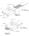
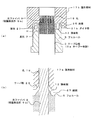
以下、本発明の実施の形態にかかる多心光コネクタ1について説明する。図1(a)は、多心光コネクタ1を示す斜視図、図1(b)は図1(a)のA−A線断面図、図2(a)は図1(a)のB−B線断面図である。
Hereinafter, a multi-fiber
多心光コネクタ1は樹脂製のフェルール5にテープ心線3が挿入されて固定される。フェルール5には長手方向に貫通する長穴7が形成される。長穴7はテープ心線3が挿入可能な大きさであればよいが、テープ心線3に対して大きなクリアランスが生じないように設定される。フェルール5の端面にはガイド機構であるガイド穴11が設けられる。なお、ガイド穴11の位置、大きさ、形状等は図示した例に限られない。
The multi-fiber
フェルール5に挿入されるテープ心線3は、テープ(および被覆部)が被覆されたテープ一体部9aと、その先端側にテープおよび被覆が除去され、光ファイバ9が露出する被覆除去部9bで構成される。なお、光ファイバ9は例えば125μm径であり、被覆部においては250μmとなる。したがって、被覆除去部9bにおいては、光ファイバ9は略250μmピッチで配置される。
The
光ファイバ9の外周は、全周に渡って接着剤13が設けられ、長穴7の内面に固定される。すなわち、光ファイバ9は直接長穴7とは接触しない。なお、光ファイバ9の配置、本数等については、図示した例に限られない。 The outer periphery of the optical fiber 9 is provided with an adhesive 13 over the entire periphery, and is fixed to the inner surface of the long hole 7. That is, the optical fiber 9 does not directly contact the long hole 7. In addition, about arrangement | positioning, the number, etc. of the optical fiber 9, it is not restricted to the illustrated example.
本発明においては、図2(b)に示すような多心光コネクタ1aとしてもよい。多心光コネクタ1aでは、フェルール5の長穴7幅が先端にいくにつれて縮径するテーパ部15が形成される。テーパ部15は、長穴7の先端幅が、テープ一体部9aの幅よりも狭く、光ファイバ9の整列幅よりも広くなるように形成される。すなわち、テープ一体部9aはテーパ部15まで挿入されて、それ以上挿入されることはない。また、光ファイバ9と長穴7とは接触することはない。このようにすることで、テープ心線が過剰に差し込まれることが防止され、被覆除去部の長さを一定にすることができる。 In the present invention, a multi-fiber optical connector 1a as shown in FIG. In the multi-fiber optical connector 1a, a tapered portion 15 having a diameter reduced as the width of the long hole 7 of the ferrule 5 reaches the tip is formed. The tapered portion 15 is formed such that the tip width of the long hole 7 is narrower than the width of the tape integrated portion 9 a and wider than the alignment width of the optical fibers 9. That is, the tape integrated portion 9a is inserted up to the taper portion 15 and is not inserted further. Moreover, the optical fiber 9 and the long hole 7 do not contact. By doing in this way, it is prevented that a tape core wire is inserted excessively, and the length of a coating removal part can be made constant.
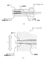
次に、多心光コネクタ1の製造方法について説明する。まず、図3(a)に示すように、あらかじめ先端部分のテープおよび被覆を除去して被覆除去部9bを形成したテープ心線3を、フェルール5の後端から長穴7に挿入する(図中矢印C方向)。この際、図3(b)に示すように、光ファイバ9が長穴7の前方より所定長さだけ突出するようにする。
Next, a method for manufacturing the multi-fiber
次に、フェルール5の先端に接着剤13を塗布する。この際、図4に示すように、まず、光ファイバ9を規定長さよりも長めにフェルール5より突出させておき(図中矢印D方向)、接着剤13を塗布する。次に、テープ心線3をフェルール5から引き戻す(図中矢印E方向)。この際、光ファイバ9の周囲に付着した接着剤13が長穴7内部に引き込まれる。このようにすることで、長穴7内部に接着剤13を塗布することができる。なお、接着剤13の塗布方法は上述した方法に限られない。例えば、フェルール5に形成された長穴7と連通する穴から接着剤を流し込んでもよく、あらかじめ接着剤13を塗布した後に、光ファイバ9を挿入してもよい。
Next, the adhesive 13 is applied to the tip of the ferrule 5. At this time, as shown in FIG. 4, first, the optical fiber 9 is protruded from the ferrule 5 longer than the specified length (in the direction of arrow D in the figure), and the adhesive 13 is applied. Next, the
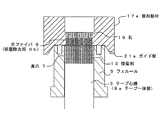
図5は、整列部材17を示す図であり、図5(a)は斜視図、図5(b)は図5(a)のF部拡大図である。整列部材17は、例えば樹脂製の部材であり、一方の端面には複数の孔19が所定ピッチで整列配置される。なお、整列部である孔19は貫通孔であってもよく、所定深さで形成されてもよい。孔19の両側方には、ガイド機構であるガイドピン21が設けられる。ガイドピン21は前述したフェルール5のガイド穴11に対応する位置、大きさで設けられる。なお、整列部材17としては、従来使用されていたフェルール(特許文献1)等をそのまま用いることもできる。
5A and 5B are diagrams showing the alignment member 17, in which FIG. 5A is a perspective view, and FIG. 5B is an enlarged view of a portion F in FIG. 5A. The alignment member 17 is, for example, a resin member, and a plurality of
図5(b)に示すように、孔19の端部(後述する光ファイバの挿入側)は、端部にいくにつれて拡径するテーパ部23が形成される。なお、孔19の径は、挿入される光ファイバ径よりもわずかに大きく設定される。
As shown in FIG. 5B, the end portion of the hole 19 (on the optical fiber insertion side described later) is formed with a tapered portion 23 whose diameter increases toward the end portion. The diameter of the
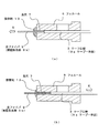
図6は、整列部材17をフェルールに取り付ける状態を示す図である。図6(a)に示すように、整列部材17の孔19側(ガイドピン21側)をフェルール5に対向させて、ガイドピン21をガイド穴11に挿入する(図中矢印G方向)。この際、ガイドピン21の長さを、光ファイバ9の突出長さよりも長く設定することで、まず、ガイドピン21がガイド穴11に挿入され、整列部材17とフェルール5との位置を規制することができる。この状態からさらに整列部材17をフェルール側に挿入することで、光ファイバ9の先端を孔19に挿入することができる。
FIG. 6 is a view showing a state in which the alignment member 17 is attached to the ferrule. As shown in FIG. 6 (a), the guide pin 21 is inserted into the guide hole 11 with the
なお、この際、フェルール5の端面を上方に向け、上方から整列部材17をフェルール5に対向させることが望ましい。接着剤13が整列部材17方向に流れることを防止するためである。また、光ファイバ9の先端を孔19に挿入した状態で、接着剤13を塗布してもよい。この場合には、整列部材17に接着剤が付着しないようにする。また、整列部材17自体を接着剤が固着しないようにフッ素樹脂等で構成してもよい。
At this time, it is desirable that the end surface of the ferrule 5 is directed upward and the alignment member 17 is opposed to the ferrule 5 from above. This is to prevent the adhesive 13 from flowing in the direction of the alignment member 17. Alternatively, the adhesive 13 may be applied with the tip of the optical fiber 9 inserted into the
図6(b)に示すように、光ファイバ9が、対応する孔19に全て挿入されると、それぞれの光ファイバ9の位置が孔19の位置によって規制される。すなわち、孔19と略同一の精度で整列させることができる。この状態で、接着剤13を硬化させて光ファイバ9をフェルール5(長穴7内面)に固定する。
As shown in FIG. 6B, when the optical fibers 9 are all inserted into the corresponding
なお、整列部材とフェルールとの位置決めを行うガイド機構は、ガイドピンおよびガイド穴には限られない。例えば、図7に示すように、フェルール5との対向面側に、テーパ形状のガイド部21aを形成してもよい。このようにすることで、フェルール5に対して整列部材17aの位置決めを行うことができる。すなわち、フェルール5に対して位置決めを行うことができる機構であれば、いずれのガイド機構であってもよい。 The guide mechanism for positioning the alignment member and the ferrule is not limited to the guide pin and the guide hole. For example, as shown in FIG. 7, a tapered guide portion 21 a may be formed on the side facing the ferrule 5. By doing so, the alignment member 17a can be positioned with respect to the ferrule 5. That is, any guide mechanism may be used as long as the mechanism can perform positioning with respect to the ferrule 5.
また、図8に示すような整列部材17bを用いることもできる。図8(a)は整列部材17bをフェルール5に取り付けた状態を示す図であり、図8(b)は図8(a)のH部拡大図である。整列部材17bには、フェルール5との対向面の一部に凸状の段差15(または突起)が形成される。すなわち、フェルール5に取り付けた状態で、フェルール5と整列部材17bとの互いの対向面の間には隙間27が形成される。 An alignment member 17b as shown in FIG. 8 can also be used. FIG. 8A is a view showing a state in which the alignment member 17b is attached to the ferrule 5, and FIG. 8B is an enlarged view of a portion H in FIG. 8A. A convex step 15 (or protrusion) is formed on a part of the surface facing the ferrule 5 on the alignment member 17b. That is, the gap 27 is formed between the opposing surfaces of the ferrule 5 and the alignment member 17b in a state of being attached to the ferrule 5.
図8(b)に示すように、フェルール5の端面には接着剤13が付着するが、隙間27を形成することで、接着剤13が整列部材17bに付着することを防止することができる。また、孔19の端面にはテーパ部23が形成されるため、光ファイバ9の表面に表面張力によって盛り上がった接着剤13に対しても、確実に整列部材17bへの付着を防止することができる。
As shown in FIG. 8B, the adhesive 13 adheres to the end face of the ferrule 5, but by forming the gap 27, it is possible to prevent the adhesive 13 from adhering to the alignment member 17b. Further, since the tapered portion 23 is formed on the end surface of the
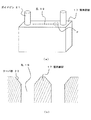
接着剤13が硬化した後、整列部材を撤去する。その後、図9に示すように、フェルール5より突出する光ファイバ9とフェルール5の端面の一部を研磨面29で研磨する。以上により、長穴7内部で精度よく光ファイバ9が整列した状態の多心光コネクタ1を得ることができる。
After the adhesive 13 is cured, the alignment member is removed. Thereafter, as shown in FIG. 9, the optical fiber 9 protruding from the ferrule 5 and a part of the end face of the ferrule 5 are polished by the polishing surface 29. As described above, it is possible to obtain the multi-fiber
本発明によれば、フェルール5に孔が形成されずに長穴が形成されるため、フェルールの製造に際してコアピンを用いる必要がない。したがってフェルールの製造性が優れる。また、光ファイバ9の整列精度がフェルールではなく整列部材によって規制されるため、フェルール5には高い精度が不要である。このため、特殊な樹脂を使用する必要がない。 According to the present invention, since a long hole is formed without forming a hole in the ferrule 5, it is not necessary to use a core pin when manufacturing the ferrule. Therefore, the ferrule manufacturability is excellent. Further, since the alignment accuracy of the optical fiber 9 is regulated not by the ferrule but by the alignment member, the ferrule 5 does not require high accuracy. For this reason, it is not necessary to use special resin.
また、光ファイバは、整列部材によって位置決めがなされるため、極めて高い精度で整列させることができる。また、整列部材の孔19の端部にはテーパ部23が形成されるため、光ファイバ9の挿入性が良く、また、接着剤13が整列部材に付着することも防止することができる。
Further, since the optical fibers are positioned by the alignment member, they can be aligned with extremely high accuracy. Moreover, since the taper part 23 is formed in the edge part of the
また、整列部材の端面に段差25を設けることで、フェルール5の端面との間に隙間27を形成することができる。このため、接着剤13が整列部材に付着することを防止することができる。 Further, by providing the step 25 on the end face of the alignment member, a gap 27 can be formed between the end face of the ferrule 5. For this reason, it can prevent that the adhesive agent 13 adheres to an alignment member.
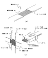
次に、第2の実施の形態について説明する。図10は整列部材30を用いて多心光コネクタを製造する方法を示す図である。なお、以下の実施形態において、図1〜図9に示した構成と同一の機能を奏する構成は図1〜図9と同一の符号を付し、重複する説明を省略する。 Next, a second embodiment will be described. FIG. 10 is a diagram illustrating a method of manufacturing a multi-fiber optical connector using the alignment member 30. Note that, in the following embodiments, configurations having the same functions as those shown in FIGS. 1 to 9 are denoted by the same reference numerals as those in FIGS.
図10(a)に示すように、整列部材30は光ファイバ9の本数に応じた複数の溝31が設けられる。整列部である溝31の個々の幅は光ファイバ9の径に対応する。複数の溝31の両側方には、ガイド機構としてのガイド溝35が設けられる。ガイド溝35はフェルール5aのガイド穴に挿入されたガイドピン33と対応する。なお、本実施例では、光ファイバ9が2段に設けられる例を示すが、本発明はこれに限られない。また、同様に前述した実施例においても光ファイバ9を複数段に形成してもよい。 As shown in FIG. 10A, the alignment member 30 is provided with a plurality of grooves 31 corresponding to the number of optical fibers 9. The individual widths of the grooves 31 that are the alignment portions correspond to the diameter of the optical fiber 9. Guide grooves 35 as guide mechanisms are provided on both sides of the plurality of grooves 31. The guide groove 35 corresponds to the guide pin 33 inserted into the guide hole of the ferrule 5a. In this embodiment, an example in which the optical fibers 9 are provided in two stages is shown, but the present invention is not limited to this. Similarly, in the above-described embodiments, the optical fibers 9 may be formed in a plurality of stages.
まず、図10(a)に示すように、整列部材30をフェルール5aに取り付ける(図中矢印I方向)。この際、溝31の上端部には、図示を省略したテーパ部(図5(b)のテーパ部23と同様のテーパ部)が形成される。なお、この場合も、前述の通り、フェルール5aの端面を上方に向けた状態で整列部材30を取り付けることが望ましい。 First, as shown in FIG. 10A, the alignment member 30 is attached to the ferrule 5a (in the direction of arrow I in the figure). At this time, a tapered portion (not shown) is formed at the upper end portion of the groove 31 (the same tapered portion as the tapered portion 23 in FIG. 5B). In this case as well, as described above, it is desirable to attach the alignment member 30 with the end face of the ferrule 5a facing upward.
図10(b)は光ファイバ9が整列部材30の溝31に挿入された状態の正面図である。図10(b)に示すように、光ファイバ9は、それぞれの溝31に挿入されることで、溝31のピッチに応じたピッチで整列される。すなわち、テープ心線3における光ファイバ9の配列方向(図中矢印J方向)は、溝31によって位置決めがなされる。 FIG. 10B is a front view showing a state in which the optical fiber 9 is inserted into the groove 31 of the alignment member 30. As shown in FIG. 10B, the optical fibers 9 are aligned in a pitch corresponding to the pitch of the grooves 31 by being inserted into the respective grooves 31. That is, the arrangement direction of the optical fibers 9 in the tape core wire 3 (the direction of arrow J in the figure) is positioned by the groove 31.
図11(a)は、フェルール5aの断面図であり、図11(b)は図11(a)のK部拡大図である。フェルール5aは、長穴7が2段形成される。図11(b)に示すように、長穴7の先端部は高さ方向が縮径される。すなわち、長穴7の先端部の高さは、光ファイバ9が挿入可能な範囲で光ファイバ9の外径よりもわずかに大きく設定される。したがって、光ファイバ9の上下方向(図中矢印L方向)は長穴7の先端で位置決めがなされる。 FIG. 11A is a cross-sectional view of the ferrule 5a, and FIG. 11B is an enlarged view of a portion K in FIG. 11A. The ferrule 5a has two long slots 7 formed therein. As shown in FIG. 11 (b), the tip of the elongated hole 7 is reduced in diameter in the height direction. That is, the height of the tip of the long hole 7 is set to be slightly larger than the outer diameter of the optical fiber 9 within a range in which the optical fiber 9 can be inserted. Accordingly, the optical fiber 9 is positioned at the tip of the long hole 7 in the vertical direction (in the direction of arrow L in the figure).
第2の実施形態によれば、第1の実施形態と同様の効果を得ることができる。また、整列部材30は複数の溝31が形成されるため、複数段の光ファイバを整列する場合であっても、同一の整列部材を用いることができる。また、フェルール5aは、前方が薄い平板金型を用いればよいためコアピンを用いる必要がない。また、フェルール5aでは上下方向のみの位置決めを行えばよいため、従来と比較して位置決めが容易である。 According to the second embodiment, an effect similar to that of the first embodiment can be obtained. In addition, since the alignment member 30 is formed with a plurality of grooves 31, the same alignment member can be used even when aligning a plurality of stages of optical fibers. Moreover, since the ferrule 5a should just use the flat metal mold | die with a thin front, it is not necessary to use a core pin. In addition, since the ferrule 5a only needs to be positioned in the vertical direction, the positioning is easier than in the prior art.
次に、他の実施の形態を示す。図12は、整列部材40を用いた光ファイバ9の整列方法を示す図である。図12(a)に示すように、整列部材40は、テープ心線の一部において、テープおよび被覆を除去した被覆除去部41が形成された部材である。すなわち、被覆除去部41の両側部がテープ一体部43となる。なお、テープ心線としては、整列を行う対象のテープ心線3と同一のものを用いればよい。
Next, another embodiment is shown. FIG. 12 is a diagram illustrating a method for aligning the optical fiber 9 using the alignment member 40. As shown in FIG. 12A, the alignment member 40 is a member in which a coating removal portion 41 is formed by removing the tape and the coating in a part of the tape core wire. That is, both side portions of the coating removal portion 41 become the tape integrated portion 43. In addition, what is necessary is just to use the same thing as the
まず、図12(b)に示すように、一対の整列部材40a、40bを互いに垂直に配置する。この際、互いの直交部には互いに被覆除去部41が位置するように固定する。すなわち、直交部において、整列部材40a、40bの互いの被覆除去部が直交し、格子状にファイバが形成される。この状態で、フェルール5から突出する光ファイバ9を格子状のファイバ間に挿入する。 First, as shown in FIG. 12B, the pair of alignment members 40a and 40b are arranged perpendicular to each other. At this time, the covering removal portions 41 are fixed to each other at the orthogonal portions. That is, in the orthogonal portion, the coating removal portions of the alignment members 40a and 40b are orthogonal to each other, and fibers are formed in a lattice shape. In this state, the optical fiber 9 protruding from the ferrule 5 is inserted between the lattice-like fibers.
図13は、整列部材40a、40bの直交部に光ファイバ9を挿入した状態を示す図である。前述したように、光ファイバ9は、被覆時の外径に対して約1/2の外径を有する。このため、光ファイバ9は、整列部材40a、40bのファイバで形成される格子に整列される。すなわち、整列部材40aによって配列方向のピッチが規制され、整列部材40bによって上下方向の位置が規制される。なお、各整列部材40a、40bには多少のテンションを付与することが望ましい。 FIG. 13 is a diagram illustrating a state in which the optical fiber 9 is inserted into the orthogonal portion of the alignment members 40a and 40b. As described above, the optical fiber 9 has an outer diameter that is approximately ½ of the outer diameter at the time of coating. For this reason, the optical fiber 9 is aligned with a lattice formed by the fibers of the alignment members 40a and 40b. That is, the pitch in the arrangement direction is regulated by the alignment member 40a, and the position in the vertical direction is regulated by the alignment member 40b. Note that it is desirable to apply some tension to the alignment members 40a and 40b.
以上、添付図を参照しながら、本発明の実施の形態を説明したが、本発明の技術的範囲は、前述した実施の形態に左右されない。当業者であれば、特許請求の範囲に記載された技術的思想の範疇内において各種の変更例または修正例に想到し得ることは明らかであり、それらについても当然に本発明の技術的範囲に属するものと了解される。 As mentioned above, although embodiment of this invention was described referring an accompanying drawing, the technical scope of this invention is not influenced by embodiment mentioned above. It is obvious for those skilled in the art that various modifications or modifications can be conceived within the scope of the technical idea described in the claims, and these are naturally within the technical scope of the present invention. It is understood that it belongs.
例えば、整列部材に光ファイバ9を挿入した状態で接着剤13を早急に硬化させるために、整列部材のフェルールとの対向面に、ヒータや紫外線照射機構等を設けることもできる。すなわち、使用する接着剤に応じて、接着剤の硬化機構を整列部材側に設けてもよい。 For example, in order to quickly cure the adhesive 13 with the optical fiber 9 inserted into the alignment member, a heater, an ultraviolet irradiation mechanism, or the like can be provided on the surface of the alignment member facing the ferrule. That is, an adhesive curing mechanism may be provided on the alignment member side in accordance with the adhesive to be used.
1、1a………多心光コネクタ
3………テープ心線
5、5a………フェルール
7………長穴
9………光ファイバ
9a………テープ一体部
9b………被覆除去部
11………ガイド穴
13………接着剤
15………テーパ部
17、17b、30、40、40a、40b………整列部材
19………孔
21………ガイドピン
23………テーパ部
25………段差
27………隙間
29………研磨面
31………溝
33………ガイドピン
35………ガイド溝
41………被覆除去部
43………テープ一体部
DESCRIPTION OF
Claims (7)
テープ心線が挿入可能な長穴を有するフェルールを用い、
前記フェルールの一方の端面から、前記長穴に前記テープ心線を挿入し、前記テープ心線の端部のテープおよび被覆が除去された被覆除去部を前記フェルールの他方の端面より突出させ、
前記被覆除去部を所定ピッチで整列可能な整列部材を用い、ガイド機構によって前記フェルールと前記整列部材との相対位置を合わせるとともに、前記被覆除去部の先端を前記整列部材に形成された整列部に挿入し、前記フェルールに前記整列部材を取り付け、
前記長穴と前記被覆除去部との隙間に塗布された接着剤によって、前記被覆除去部を前記長穴内に固定し、
前記整列部材を撤去後、前記フェルールの前記他方の端面を研磨することを特徴とする多心光コネクタの製造方法。 A method of manufacturing a multi-fiber optical connector,
Using a ferrule with a long hole into which the tape core can be inserted,
From one end surface of the ferrule, the tape core wire is inserted into the elongated hole, and the coating removal portion from which the tape and coating of the end portion of the tape core wire are removed protrudes from the other end surface of the ferrule,
An alignment member capable of aligning the coating removal portion at a predetermined pitch is used, the relative positions of the ferrule and the alignment member are aligned by a guide mechanism, and the tip of the coating removal portion is aligned with the alignment portion formed on the alignment member. Insert and attach the alignment member to the ferrule;
With the adhesive applied to the gap between the elongated hole and the sheath removing portion, the sheath removing portion is fixed in the elongated hole,
A method of manufacturing a multi-fiber optical connector, wherein after removing the alignment member, the other end face of the ferrule is polished.
それぞれの前記被覆除去部の縦横の位置は、前記整列部によって規制されることを特徴とする請求項1または請求項2に記載の多心光コネクタの製造方法。 The alignment portion of the alignment member is a plurality of holes arranged at a predetermined pitch into which the tip of the coating removal portion can be inserted corresponding to the outer diameter of the coating removal portion,
3. The method of manufacturing a multi-fiber optical connector according to claim 1, wherein vertical and horizontal positions of each of the covering removal portions are regulated by the alignment portion.
前記整列部材の前記整列部は、前記被覆除去部の外径に対応して前記被覆除去部の先端が挿入可能な、所定ピッチで配列された複数の溝であり、
それぞれの前記被覆除去部の前記溝の配列方向の位置は、前記整列部によって規制され、
それぞれの前記被覆除去部の前記溝の配列方向とは垂直な方向の位置は、前記長穴によって規制されることを特徴とする請求項1または請求項2に記載の多心光コネクタの製造方法。 The height of the tip of the elongated hole is a height corresponding to the outer diameter of the coating removal portion,
The alignment portion of the alignment member is a plurality of grooves arranged at a predetermined pitch into which the tip of the coating removal portion can be inserted in correspondence with the outer diameter of the coating removal portion.
The positions of the grooves in the arrangement direction of the respective covering removal portions are regulated by the alignment portions,
3. The method of manufacturing a multi-fiber optical connector according to claim 1, wherein a position of each of the covering removal portions in a direction perpendicular to an arrangement direction of the grooves is regulated by the elongated holes. .
整列させる光ファイバの被覆が除去された被覆除去部を挿入可能な、所定ピッチの複数の孔または溝で構成される整列部を有し、
前記被覆除去部の挿入側の端面には凸方向の段差が形成され、光ファイバが固定されるフェルールと対向させた際に、前記フェルールの端面との間に隙間を形成可能であり、
前記整列部の被覆除去部の挿入側の端部は、端部に行くにつれて拡径するテーパ形状であること特徴とする多心光コネクタ製造用の整列部材。 An alignment member used for manufacturing a multi-fiber optical connector,
An alignment portion configured by a plurality of holes or grooves having a predetermined pitch, into which the coating removal portion from which the coating of the optical fiber to be aligned is removed can be inserted
A step in the convex direction is formed on the end surface on the insertion side of the coating removal portion, and when facing the ferrule to which the optical fiber is fixed, a gap can be formed between the end surface of the ferrule,
An alignment member for manufacturing a multi-fiber optical connector, wherein an end portion on the insertion side of the covering removal portion of the alignment portion has a tapered shape whose diameter increases toward the end portion.
光ファイバを保持するフェルールと、
前記フェルールに設けられ、少なくとも一部の幅が縮径するテーパ部が形成される長穴と、
テープ心線のテープ一体部が前記長穴の前記テーパ部まで挿入され、前記テーパ部から前記フェルールの端面までは、前記テープ心線のテープおよび被覆が除去された被覆除去部が設けられ、
前記被覆除去部の外周面と前記長穴の内周面との間には全周に渡って隙間が形成され、前記隙間には接着剤が充填され、前記被覆除去部が前記接着剤を介して前記長穴に固定されることを特徴とする多心光コネクタ。 A multi-fiber optical connector,
A ferrule holding an optical fiber;
An elongated hole provided in the ferrule, in which a tapered portion in which at least a part of the width is reduced is formed;
The tape integrated portion of the tape core wire is inserted to the taper portion of the elongated hole, and from the taper portion to the end surface of the ferrule is provided with a coating removal portion from which the tape and coating of the tape core wire are removed,
A gap is formed over the entire circumference between the outer peripheral surface of the coating removal portion and the inner peripheral surface of the elongated hole, the gap is filled with an adhesive, and the coating removal portion is interposed via the adhesive. The multi-fiber optical connector is fixed to the elongated hole.
Priority Applications (1)
| Application Number | Priority Date | Filing Date | Title |
|---|---|---|---|
| JP2011047593A JP2012185283A (en) | 2011-03-04 | 2011-03-04 | Multi-fiber optical connector, manufacturing method for multi-fiber optical connector, and alignment member for manufacturing multi-fiber optical connector |
Applications Claiming Priority (1)
| Application Number | Priority Date | Filing Date | Title |
|---|---|---|---|
| JP2011047593A JP2012185283A (en) | 2011-03-04 | 2011-03-04 | Multi-fiber optical connector, manufacturing method for multi-fiber optical connector, and alignment member for manufacturing multi-fiber optical connector |
Publications (1)
| Publication Number | Publication Date |
|---|---|
| JP2012185283A true JP2012185283A (en) | 2012-09-27 |
Family
ID=47015435
Family Applications (1)
| Application Number | Title | Priority Date | Filing Date |
|---|---|---|---|
| JP2011047593A Pending JP2012185283A (en) | 2011-03-04 | 2011-03-04 | Multi-fiber optical connector, manufacturing method for multi-fiber optical connector, and alignment member for manufacturing multi-fiber optical connector |
Country Status (1)
| Country | Link |
|---|---|
| JP (1) | JP2012185283A (en) |
Cited By (11)
| Publication number | Priority date | Publication date | Assignee | Title |
|---|---|---|---|---|
| CN103777289A (en) * | 2012-10-19 | 2014-05-07 | 泰科电子(上海)有限公司 | Multi-optical-cable fiber planting method, multi-optical-cable fiber planting device and optical-cable supporting desk |
| CN104181645A (en) * | 2013-05-28 | 2014-12-03 | 泰科电子(上海)有限公司 | Calibrating tool, calibrating method, fiber inserting assembly and fiber connector |
| CN104181644A (en) * | 2013-05-28 | 2014-12-03 | 泰科电子(上海)有限公司 | Aligning tool, aligning method, fiber inserting core assembly, and fiber connector |
| WO2014195893A1 (en) * | 2013-06-07 | 2014-12-11 | Tyco Electronics (Shanghai) Co. Ltd. | Indexing tool, calibrating method, ferrule assembly and fiber optic connector |
| CN104635304A (en) * | 2013-11-07 | 2015-05-20 | 泰科电子(上海)有限公司 | Optical fiber connector insert and manufacturing method thereof and optical fiber connector |
| CN104777561A (en) * | 2014-01-14 | 2015-07-15 | 泰科电子(上海)有限公司 | Calibration system and method, optical fiber ferrule assembly and manufacturing method as well as optical fiber connector |
| CN105223658A (en) * | 2014-07-01 | 2016-01-06 | 泰科电子(上海)有限公司 | The manufacture method of optical fiber aligning device, lock pin device and lock pin device |
| US10025041B2 (en) | 2014-07-01 | 2018-07-17 | ADC Telecommunications (Shanghai) Distribution Co. Ltd. | Ferrule assembly and ferrule device |
| JP2019079045A (en) * | 2017-10-20 | 2019-05-23 | リン, コウ・ジェLING, Kow−Je | Ferrule for optical fiber connector and positioning pattern therefor |
| US11307363B2 (en) | 2016-10-11 | 2022-04-19 | Commscope Technologies Llc | Ferrule assembly, method for manufacturing a ferrule assembly and optical fiber fixing mold |
| CN114415293A (en) * | 2022-03-29 | 2022-04-29 | 无限光通讯(深圳)有限公司 | Combined optical fiber connector |
Citations (8)
| Publication number | Priority date | Publication date | Assignee | Title |
|---|---|---|---|---|
| JPH11125748A (en) * | 1997-07-28 | 1999-05-11 | Molex Inc | Aligning device of ferrule for optical fiber cable |
| JPH11125740A (en) * | 1997-07-28 | 1999-05-11 | Molex Inc | Ferrule for optical fiber connector |
| JPH11125735A (en) * | 1997-07-28 | 1999-05-11 | Molex Inc | Assembly device for ferrule of optical fiber connector |
| JP2001083367A (en) * | 1999-09-14 | 2001-03-30 | Fujikura Ltd | Optical connector |
| JP2006184794A (en) * | 2004-12-28 | 2006-07-13 | Sumitomo Electric Ind Ltd | Optical connector and its assembling method |
| JP2009229506A (en) * | 2008-03-19 | 2009-10-08 | Furukawa Electric Co Ltd:The | Ferrule for optical connector and method of manufacturing the same |
| JP2010266826A (en) * | 2009-05-18 | 2010-11-25 | Furukawa Electric Co Ltd:The | Optical fiber array member and method of manufacturing the same |
| JP2012155167A (en) * | 2011-01-27 | 2012-08-16 | Furukawa Electric Co Ltd:The | Multi-fiber optical connector |
-
2011
- 2011-03-04 JP JP2011047593A patent/JP2012185283A/en active Pending
Patent Citations (8)
| Publication number | Priority date | Publication date | Assignee | Title |
|---|---|---|---|---|
| JPH11125748A (en) * | 1997-07-28 | 1999-05-11 | Molex Inc | Aligning device of ferrule for optical fiber cable |
| JPH11125740A (en) * | 1997-07-28 | 1999-05-11 | Molex Inc | Ferrule for optical fiber connector |
| JPH11125735A (en) * | 1997-07-28 | 1999-05-11 | Molex Inc | Assembly device for ferrule of optical fiber connector |
| JP2001083367A (en) * | 1999-09-14 | 2001-03-30 | Fujikura Ltd | Optical connector |
| JP2006184794A (en) * | 2004-12-28 | 2006-07-13 | Sumitomo Electric Ind Ltd | Optical connector and its assembling method |
| JP2009229506A (en) * | 2008-03-19 | 2009-10-08 | Furukawa Electric Co Ltd:The | Ferrule for optical connector and method of manufacturing the same |
| JP2010266826A (en) * | 2009-05-18 | 2010-11-25 | Furukawa Electric Co Ltd:The | Optical fiber array member and method of manufacturing the same |
| JP2012155167A (en) * | 2011-01-27 | 2012-08-16 | Furukawa Electric Co Ltd:The | Multi-fiber optical connector |
Cited By (13)
| Publication number | Priority date | Publication date | Assignee | Title |
|---|---|---|---|---|
| CN103777289A (en) * | 2012-10-19 | 2014-05-07 | 泰科电子(上海)有限公司 | Multi-optical-cable fiber planting method, multi-optical-cable fiber planting device and optical-cable supporting desk |
| CN104181645A (en) * | 2013-05-28 | 2014-12-03 | 泰科电子(上海)有限公司 | Calibrating tool, calibrating method, fiber inserting assembly and fiber connector |
| CN104181644A (en) * | 2013-05-28 | 2014-12-03 | 泰科电子(上海)有限公司 | Aligning tool, aligning method, fiber inserting core assembly, and fiber connector |
| WO2014195893A1 (en) * | 2013-06-07 | 2014-12-11 | Tyco Electronics (Shanghai) Co. Ltd. | Indexing tool, calibrating method, ferrule assembly and fiber optic connector |
| CN104635304A (en) * | 2013-11-07 | 2015-05-20 | 泰科电子(上海)有限公司 | Optical fiber connector insert and manufacturing method thereof and optical fiber connector |
| CN104777561A (en) * | 2014-01-14 | 2015-07-15 | 泰科电子(上海)有限公司 | Calibration system and method, optical fiber ferrule assembly and manufacturing method as well as optical fiber connector |
| CN105223658A (en) * | 2014-07-01 | 2016-01-06 | 泰科电子(上海)有限公司 | The manufacture method of optical fiber aligning device, lock pin device and lock pin device |
| CN105223658B (en) * | 2014-07-01 | 2017-10-20 | 泰科电子(上海)有限公司 | The manufacture method of optical fiber aligning device, lock pin device and lock pin device |
| US10025041B2 (en) | 2014-07-01 | 2018-07-17 | ADC Telecommunications (Shanghai) Distribution Co. Ltd. | Ferrule assembly and ferrule device |
| US10768378B2 (en) | 2014-07-01 | 2020-09-08 | Commscope Telecommunications (Shanghai) Co. Ltd. | Fiber alignment device, ferrule device and method of manufacturing the ferrule device |
| US11307363B2 (en) | 2016-10-11 | 2022-04-19 | Commscope Technologies Llc | Ferrule assembly, method for manufacturing a ferrule assembly and optical fiber fixing mold |
| JP2019079045A (en) * | 2017-10-20 | 2019-05-23 | リン, コウ・ジェLING, Kow−Je | Ferrule for optical fiber connector and positioning pattern therefor |
| CN114415293A (en) * | 2022-03-29 | 2022-04-29 | 无限光通讯(深圳)有限公司 | Combined optical fiber connector |
Similar Documents
| Publication | Publication Date | Title |
|---|---|---|
| JP2012185283A (en) | Multi-fiber optical connector, manufacturing method for multi-fiber optical connector, and alignment member for manufacturing multi-fiber optical connector | |
| EP3525020A1 (en) | Ferrule structure, ferrule structure with fiber, and method for manufacturing ferrule structure with fiber | |
| JP2016009081A (en) | Method for manufacturing optical connector and optical connector | |
| JP2007108358A (en) | Single fiber optical connector and multi-fiber optical connector | |
| WO2019234968A1 (en) | Method for manufacturing optical connector ferrule and optical connector ferrule | |
| JP5851947B2 (en) | Optical fiber guide parts | |
| US11307363B2 (en) | Ferrule assembly, method for manufacturing a ferrule assembly and optical fiber fixing mold | |
| WO2020179513A1 (en) | Optical fiber array | |
| JP2006227561A (en) | Mechanical splice, circuit component for optical communication, repeating optical transmission line, and optical transmission line | |
| JP2012155167A (en) | Multi-fiber optical connector | |
| JP6491418B2 (en) | Fiber optic connector | |
| JP2013064846A (en) | Ferrule for optical connector | |
| JP6586796B2 (en) | Connector boots, connectors and optical fiber cores with connectors | |
| JP2001066466A (en) | Optical connector | |
| JP2003050339A (en) | Optical connector ferrule and optical connector plug | |
| JP5125913B2 (en) | Optical fiber connecting element manufacturing method, molding apparatus, and optical fiber connecting element | |
| WO2018168141A1 (en) | Method for manufacturing optical connector ferrule, optical connector ferrule, and optical fiber with connector | |
| JP6926722B2 (en) | Manufacturing method and jig for optical connection parts | |
| JP2002023018A (en) | Ferrule for optical connector, optical connector and production method for optical connector | |
| JP2009193030A (en) | Optical ferrule with optical fiber | |
| US11650375B2 (en) | Ferrule and optical connector | |
| JP6907866B2 (en) | Optical connection structure and optical wiring member | |
| JP3549466B2 (en) | Ferrule for optical connector, optical connector, and method of manufacturing optical connector | |
| JP2003050336A (en) | Optical connector ferrule and optical connector plug | |
| JP2011048157A (en) | Ferrule and method for manufacturing multi-fiber optical connector |
Legal Events
| Date | Code | Title | Description |
|---|---|---|---|
| A621 | Written request for application examination |
Free format text: JAPANESE INTERMEDIATE CODE: A621 Effective date: 20140108 |
|
| A977 | Report on retrieval |
Free format text: JAPANESE INTERMEDIATE CODE: A971007 Effective date: 20140528 |
|
| A131 | Notification of reasons for refusal |
Free format text: JAPANESE INTERMEDIATE CODE: A131 Effective date: 20150127 |
|
| A02 | Decision of refusal |
Free format text: JAPANESE INTERMEDIATE CODE: A02 Effective date: 20150616 |