WO2024034601A1 - 電気化学素子 - Google Patents
電気化学素子 Download PDFInfo
- Publication number
- WO2024034601A1 WO2024034601A1 PCT/JP2023/028906 JP2023028906W WO2024034601A1 WO 2024034601 A1 WO2024034601 A1 WO 2024034601A1 JP 2023028906 W JP2023028906 W JP 2023028906W WO 2024034601 A1 WO2024034601 A1 WO 2024034601A1
- Authority
- WO
- WIPO (PCT)
- Prior art keywords
- conductive plate
- electrode layer
- insertion hole
- concave container
- power generation
- Prior art date
- Legal status (The legal status is an assumption and is not a legal conclusion. Google has not performed a legal analysis and makes no representation as to the accuracy of the status listed.)
- Ceased
Links
Images






Classifications
-
- H—ELECTRICITY
- H01—ELECTRIC ELEMENTS
- H01G—CAPACITORS; CAPACITORS, RECTIFIERS, DETECTORS, SWITCHING DEVICES, LIGHT-SENSITIVE OR TEMPERATURE-SENSITIVE DEVICES OF THE ELECTROLYTIC TYPE
- H01G11/00—Hybrid capacitors, i.e. capacitors having different positive and negative electrodes; Electric double-layer [EDL] capacitors; Processes for the manufacture thereof or of parts thereof
- H01G11/74—Terminals, e.g. extensions of current collectors
-
- H—ELECTRICITY
- H01—ELECTRIC ELEMENTS
- H01M—PROCESSES OR MEANS, e.g. BATTERIES, FOR THE DIRECT CONVERSION OF CHEMICAL ENERGY INTO ELECTRICAL ENERGY
- H01M50/00—Constructional details or processes of manufacture of the non-active parts of electrochemical cells other than fuel cells, e.g. hybrid cells
- H01M50/50—Current conducting connections for cells or batteries
- H01M50/531—Electrode connections inside a battery casing
- H01M50/536—Electrode connections inside a battery casing characterised by the method of fixing the leads to the electrodes, e.g. by welding
-
- H—ELECTRICITY
- H01—ELECTRIC ELEMENTS
- H01G—CAPACITORS; CAPACITORS, RECTIFIERS, DETECTORS, SWITCHING DEVICES, LIGHT-SENSITIVE OR TEMPERATURE-SENSITIVE DEVICES OF THE ELECTROLYTIC TYPE
- H01G11/00—Hybrid capacitors, i.e. capacitors having different positive and negative electrodes; Electric double-layer [EDL] capacitors; Processes for the manufacture thereof or of parts thereof
- H01G11/78—Cases; Housings; Encapsulations; Mountings
-
- H—ELECTRICITY
- H01—ELECTRIC ELEMENTS
- H01G—CAPACITORS; CAPACITORS, RECTIFIERS, DETECTORS, SWITCHING DEVICES, LIGHT-SENSITIVE OR TEMPERATURE-SENSITIVE DEVICES OF THE ELECTROLYTIC TYPE
- H01G11/00—Hybrid capacitors, i.e. capacitors having different positive and negative electrodes; Electric double-layer [EDL] capacitors; Processes for the manufacture thereof or of parts thereof
- H01G11/78—Cases; Housings; Encapsulations; Mountings
- H01G11/82—Fixing or assembling a capacitive element in a housing, e.g. mounting electrodes, current collectors or terminals in containers or encapsulations
-
- H—ELECTRICITY
- H01—ELECTRIC ELEMENTS
- H01M—PROCESSES OR MEANS, e.g. BATTERIES, FOR THE DIRECT CONVERSION OF CHEMICAL ENERGY INTO ELECTRICAL ENERGY
- H01M10/00—Secondary cells; Manufacture thereof
- H01M10/05—Accumulators with non-aqueous electrolyte
- H01M10/052—Li-accumulators
- H01M10/0525—Rocking-chair batteries, i.e. batteries with lithium insertion or intercalation in both electrodes; Lithium-ion batteries
-
- H—ELECTRICITY
- H01—ELECTRIC ELEMENTS
- H01M—PROCESSES OR MEANS, e.g. BATTERIES, FOR THE DIRECT CONVERSION OF CHEMICAL ENERGY INTO ELECTRICAL ENERGY
- H01M10/00—Secondary cells; Manufacture thereof
- H01M10/05—Accumulators with non-aqueous electrolyte
- H01M10/056—Accumulators with non-aqueous electrolyte characterised by the materials used as electrolytes, e.g. mixed inorganic/organic electrolytes
- H01M10/0561—Accumulators with non-aqueous electrolyte characterised by the materials used as electrolytes, e.g. mixed inorganic/organic electrolytes the electrolyte being constituted of inorganic materials only
- H01M10/0562—Solid materials
-
- H—ELECTRICITY
- H01—ELECTRIC ELEMENTS
- H01M—PROCESSES OR MEANS, e.g. BATTERIES, FOR THE DIRECT CONVERSION OF CHEMICAL ENERGY INTO ELECTRICAL ENERGY
- H01M10/00—Secondary cells; Manufacture thereof
- H01M10/05—Accumulators with non-aqueous electrolyte
- H01M10/058—Construction or manufacture
- H01M10/0585—Construction or manufacture of accumulators having only flat construction elements, i.e. flat positive electrodes, flat negative electrodes and flat separators
-
- H—ELECTRICITY
- H01—ELECTRIC ELEMENTS
- H01M—PROCESSES OR MEANS, e.g. BATTERIES, FOR THE DIRECT CONVERSION OF CHEMICAL ENERGY INTO ELECTRICAL ENERGY
- H01M50/00—Constructional details or processes of manufacture of the non-active parts of electrochemical cells other than fuel cells, e.g. hybrid cells
- H01M50/10—Primary casings; Jackets or wrappings
- H01M50/102—Primary casings; Jackets or wrappings characterised by their shape or physical structure
- H01M50/103—Primary casings; Jackets or wrappings characterised by their shape or physical structure prismatic or rectangular
-
- H—ELECTRICITY
- H01—ELECTRIC ELEMENTS
- H01M—PROCESSES OR MEANS, e.g. BATTERIES, FOR THE DIRECT CONVERSION OF CHEMICAL ENERGY INTO ELECTRICAL ENERGY
- H01M50/00—Constructional details or processes of manufacture of the non-active parts of electrochemical cells other than fuel cells, e.g. hybrid cells
- H01M50/10—Primary casings; Jackets or wrappings
- H01M50/102—Primary casings; Jackets or wrappings characterised by their shape or physical structure
- H01M50/109—Primary casings; Jackets or wrappings characterised by their shape or physical structure of button or coin shape
-
- H—ELECTRICITY
- H01—ELECTRIC ELEMENTS
- H01M—PROCESSES OR MEANS, e.g. BATTERIES, FOR THE DIRECT CONVERSION OF CHEMICAL ENERGY INTO ELECTRICAL ENERGY
- H01M50/00—Constructional details or processes of manufacture of the non-active parts of electrochemical cells other than fuel cells, e.g. hybrid cells
- H01M50/10—Primary casings; Jackets or wrappings
- H01M50/102—Primary casings; Jackets or wrappings characterised by their shape or physical structure
- H01M50/11—Primary casings; Jackets or wrappings characterised by their shape or physical structure having a chip structure, e.g. micro-sized batteries integrated on chips
-
- H—ELECTRICITY
- H01—ELECTRIC ELEMENTS
- H01M—PROCESSES OR MEANS, e.g. BATTERIES, FOR THE DIRECT CONVERSION OF CHEMICAL ENERGY INTO ELECTRICAL ENERGY
- H01M50/00—Constructional details or processes of manufacture of the non-active parts of electrochemical cells other than fuel cells, e.g. hybrid cells
- H01M50/10—Primary casings; Jackets or wrappings
- H01M50/147—Lids or covers
- H01M50/148—Lids or covers characterised by their shape
-
- H—ELECTRICITY
- H01—ELECTRIC ELEMENTS
- H01M—PROCESSES OR MEANS, e.g. BATTERIES, FOR THE DIRECT CONVERSION OF CHEMICAL ENERGY INTO ELECTRICAL ENERGY
- H01M50/00—Constructional details or processes of manufacture of the non-active parts of electrochemical cells other than fuel cells, e.g. hybrid cells
- H01M50/10—Primary casings; Jackets or wrappings
- H01M50/147—Lids or covers
- H01M50/148—Lids or covers characterised by their shape
- H01M50/153—Lids or covers characterised by their shape for button or coin cells
-
- H—ELECTRICITY
- H01—ELECTRIC ELEMENTS
- H01M—PROCESSES OR MEANS, e.g. BATTERIES, FOR THE DIRECT CONVERSION OF CHEMICAL ENERGY INTO ELECTRICAL ENERGY
- H01M50/00—Constructional details or processes of manufacture of the non-active parts of electrochemical cells other than fuel cells, e.g. hybrid cells
- H01M50/10—Primary casings; Jackets or wrappings
- H01M50/183—Sealing members
- H01M50/186—Sealing members characterised by the disposition of the sealing members
-
- H—ELECTRICITY
- H01—ELECTRIC ELEMENTS
- H01M—PROCESSES OR MEANS, e.g. BATTERIES, FOR THE DIRECT CONVERSION OF CHEMICAL ENERGY INTO ELECTRICAL ENERGY
- H01M50/00—Constructional details or processes of manufacture of the non-active parts of electrochemical cells other than fuel cells, e.g. hybrid cells
- H01M50/20—Mountings; Secondary casings or frames; Racks, modules or packs; Suspension devices; Shock absorbers; Transport or carrying devices; Holders
- H01M50/202—Casings or frames around the primary casing of a single cell or a single battery
-
- H—ELECTRICITY
- H01—ELECTRIC ELEMENTS
- H01M—PROCESSES OR MEANS, e.g. BATTERIES, FOR THE DIRECT CONVERSION OF CHEMICAL ENERGY INTO ELECTRICAL ENERGY
- H01M50/00—Constructional details or processes of manufacture of the non-active parts of electrochemical cells other than fuel cells, e.g. hybrid cells
- H01M50/50—Current conducting connections for cells or batteries
- H01M50/531—Electrode connections inside a battery casing
- H01M50/533—Electrode connections inside a battery casing characterised by the shape of the leads or tabs
-
- H—ELECTRICITY
- H01—ELECTRIC ELEMENTS
- H01M—PROCESSES OR MEANS, e.g. BATTERIES, FOR THE DIRECT CONVERSION OF CHEMICAL ENERGY INTO ELECTRICAL ENERGY
- H01M50/00—Constructional details or processes of manufacture of the non-active parts of electrochemical cells other than fuel cells, e.g. hybrid cells
- H01M50/50—Current conducting connections for cells or batteries
- H01M50/531—Electrode connections inside a battery casing
- H01M50/54—Connection of several leads or tabs of plate-like electrode stacks, e.g. electrode pole straps or bridges
-
- H—ELECTRICITY
- H01—ELECTRIC ELEMENTS
- H01M—PROCESSES OR MEANS, e.g. BATTERIES, FOR THE DIRECT CONVERSION OF CHEMICAL ENERGY INTO ELECTRICAL ENERGY
- H01M50/00—Constructional details or processes of manufacture of the non-active parts of electrochemical cells other than fuel cells, e.g. hybrid cells
- H01M50/50—Current conducting connections for cells or batteries
- H01M50/543—Terminals
- H01M50/545—Terminals formed by the casing of the cells
-
- H—ELECTRICITY
- H01—ELECTRIC ELEMENTS
- H01M—PROCESSES OR MEANS, e.g. BATTERIES, FOR THE DIRECT CONVERSION OF CHEMICAL ENERGY INTO ELECTRICAL ENERGY
- H01M50/00—Constructional details or processes of manufacture of the non-active parts of electrochemical cells other than fuel cells, e.g. hybrid cells
- H01M50/50—Current conducting connections for cells or batteries
- H01M50/543—Terminals
- H01M50/552—Terminals characterised by their shape
- H01M50/559—Terminals adapted for cells having curved cross-section, e.g. round, elliptic or button cells
-
- H—ELECTRICITY
- H01—ELECTRIC ELEMENTS
- H01M—PROCESSES OR MEANS, e.g. BATTERIES, FOR THE DIRECT CONVERSION OF CHEMICAL ENERGY INTO ELECTRICAL ENERGY
- H01M50/00—Constructional details or processes of manufacture of the non-active parts of electrochemical cells other than fuel cells, e.g. hybrid cells
- H01M50/50—Current conducting connections for cells or batteries
- H01M50/543—Terminals
- H01M50/552—Terminals characterised by their shape
- H01M50/559—Terminals adapted for cells having curved cross-section, e.g. round, elliptic or button cells
- H01M50/56—Cup shaped terminals
-
- H—ELECTRICITY
- H01—ELECTRIC ELEMENTS
- H01M—PROCESSES OR MEANS, e.g. BATTERIES, FOR THE DIRECT CONVERSION OF CHEMICAL ENERGY INTO ELECTRICAL ENERGY
- H01M2300/00—Electrolytes
- H01M2300/0017—Non-aqueous electrolytes
- H01M2300/0065—Solid electrolytes
-
- H—ELECTRICITY
- H01—ELECTRIC ELEMENTS
- H01M—PROCESSES OR MEANS, e.g. BATTERIES, FOR THE DIRECT CONVERSION OF CHEMICAL ENERGY INTO ELECTRICAL ENERGY
- H01M50/00—Constructional details or processes of manufacture of the non-active parts of electrochemical cells other than fuel cells, e.g. hybrid cells
- H01M50/10—Primary casings; Jackets or wrappings
- H01M50/183—Sealing members
-
- H—ELECTRICITY
- H01—ELECTRIC ELEMENTS
- H01M—PROCESSES OR MEANS, e.g. BATTERIES, FOR THE DIRECT CONVERSION OF CHEMICAL ENERGY INTO ELECTRICAL ENERGY
- H01M50/00—Constructional details or processes of manufacture of the non-active parts of electrochemical cells other than fuel cells, e.g. hybrid cells
- H01M50/50—Current conducting connections for cells or batteries
- H01M50/543—Terminals
- H01M50/547—Terminals characterised by the disposition of the terminals on the cells
- H01M50/55—Terminals characterised by the disposition of the terminals on the cells on the same side of the cell
-
- Y—GENERAL TAGGING OF NEW TECHNOLOGICAL DEVELOPMENTS; GENERAL TAGGING OF CROSS-SECTIONAL TECHNOLOGIES SPANNING OVER SEVERAL SECTIONS OF THE IPC; TECHNICAL SUBJECTS COVERED BY FORMER USPC CROSS-REFERENCE ART COLLECTIONS [XRACs] AND DIGESTS
- Y02—TECHNOLOGIES OR APPLICATIONS FOR MITIGATION OR ADAPTATION AGAINST CLIMATE CHANGE
- Y02E—REDUCTION OF GREENHOUSE GAS [GHG] EMISSIONS, RELATED TO ENERGY GENERATION, TRANSMISSION OR DISTRIBUTION
- Y02E60/00—Enabling technologies; Technologies with a potential or indirect contribution to GHG emissions mitigation
- Y02E60/10—Energy storage using batteries
Definitions
- the present disclosure relates to an electrochemical device in which a power generation element is sealed within a case.
- a power generation element is housed in an internal space formed by a concave container and a lid material covering the opening of the concave container.
- Patent Document 1 JP 2012-69508A discloses an electrochemical cell with stable electrochemical properties.
- An electrochemical cell has a sealed container.
- the sealed container consists of a base member and a lid member.
- a storage space in which an electrochemical element is stored is formed between both members.
- An elastic member that presses the electrochemical element is disposed between the lid member and the electrochemical element.
- Patent Document 1 discloses, as an elastic member, a plate spring bent in a V-shape in cross-sectional view, or a diaphragm-shaped spring formed in a concave curved shape that is warped from the center toward the outer peripheral edge.
- Patent Document 2 discloses that a battery element having a first electrode, a solid electrolyte, and a second electrode is connected to a metal case, a metal sealing plate, and a gasket interposed between them.
- a coin-type lithium secondary battery which is enclosed in a container having a lithium battery and a conductive elastic body is disposed between the battery element and a metal case or a metal sealing plate.
- the conductive elastic body can press the laminate with a pressure of 0.1 MPa or more, and can increase the contact pressure between the first electrode and the second electrode and the solid electrolyte. As a result, a decrease in current density can be suppressed.
- the width from the center to the outer edge in the height direction (the width of the entire spring)
- the spring locking position is at the upper end in the height direction, which is the outer periphery, there is a large gap between the lid member and the electrochemical element, including the gap between the elastic member and the lid member. This results in the creation of voids, which becomes a factor that prevents the electrochemical cell from increasing its capacity.
- an object of the present disclosure is to provide an electrochemical element that can maintain good electrical connection.
- the electrochemical device includes a case including a concave container having a bottom and a side wall, a lid material covering an opening of the concave container, and a first electrode sealed in the case and disposed on the bottom side.
- a power generation element having a second electrode layer disposed on the side of the power generation element and the cover material, and an isolation layer disposed between the first electrode layer and the second electrode layer; and a power generation element disposed between the power generation element and the cover material. It is equipped with a conductive plate.
- the first electrode layer is electrically connected to a first conduction path leading from the inside of the case to the outside.
- the second electrode layer is electrically connected to a second conduction path leading from the inside of the case to the outside via the conductive plate.
- the concave container has an insertion hole having an opening in the upper end surface of the side wall.
- the conductive plate extends from the edge of the conductive plate, is inserted into the insertion hole, and has an elastic locking portion for attaching the conductive plate to the recessed container. The elastic locking portion inserted into the insertion hole presses against the side surface of the insertion hole.
- FIG. 1 is a sectional view showing an electrochemical device according to a first embodiment.
- FIG. 2 is an external perspective view showing the concave container of the electrochemical device of FIG. 1.
- FIG. 3 is a plan view showing the electrochemical element of FIG. 1 (excluding the lid material and the conductive plate).
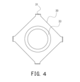
- FIG. 4 is a plan view showing a conductive plate of the electrochemical device of FIG. 1.
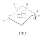
- FIG. 5 is an external perspective view showing a modification of the conductive plate of the electrochemical device shown in FIG.
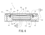
- FIG. 6 is a sectional view showing an electrochemical device according to the second embodiment.
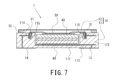
- FIG. 7 is a sectional view showing an electrochemical device according to a third embodiment.
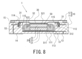
- FIG. 8 is a sectional view showing an electrochemical device according to a fourth embodiment.
- FIG. 1 is a sectional view showing an electrochemical device according to a first embodiment.
- FIG. 2 is an external perspective view showing the concave container of the electrochemical device of FIG. 1.
- FIG. 3 is a plan
- FIG. 9 is an external perspective view showing a concave container of an electrochemical device according to Modification Example 1.
- FIG. 10 is an external perspective view showing a conductive plate according to Modification 2.
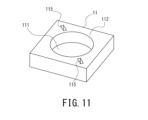
- FIG. 11 is an external perspective view showing a concave container corresponding to the conductive plate shown in FIG. 10.
- FIG. 12 is an external perspective view showing a concave container of an electrochemical device according to Modification Example 3.
- FIG. 13 is a cross-sectional view showing an electrochemical device according to modification example 4.
- FIG. 14 is an external perspective view showing a concave container according to modification 6.
- An electrochemical device includes a case including a concave container having a bottom and a side wall, a lid material covering an opening of the concave container, and a first container sealed in the case and disposed on the bottom side.
- a power generation element having an electrode layer, a second electrode layer disposed on the lid material side, and an isolation layer disposed between the first electrode layer and the second electrode layer, and a power generation element disposed between the power generation element and the lid material.
- the conductive plate may be provided with a conductive plate.
- the first electrode layer may be electrically connected to a first conduction path leading from the inside of the case to the outside.
- the second electrode layer may be electrically connected to a second conduction path leading from the inside of the case to the outside via a conductive plate.
- the concave container may have an insertion hole having an opening in the upper end surface of the side wall.
- the conductive plate may have an elastic lock extending from the edge of the conductive plate and inserted into the insertion hole to attach the conductive plate to the recessed container. The elastic locking portion inserted into the insertion hole may press against the side surface of the insertion hole.
- the conductive plate is fixed to the concave container by the elastic force of the elastic locking portion, so that a good electrical connection can be maintained.
- the conductive plate can be easily attached to the concave container because the elastic locking portion may be inserted from above the upper end surface of the concave container toward the insertion hole.
- the elastic locking portion may have a tip portion folded back in a direction opposite to the direction of insertion into the insertion hole.
- the elastic locking portion may have a corrugated plate shape.
- An electrochemical device includes a case including a concave container having a bottom and a side wall, a lid material covering an opening of the concave container, and a first electrode sealed in the case and disposed on the bottom side.
- An exterior material including a second electrode terminal arranged on the terminal and lid side, and an exterior material enclosed within the exterior material and arranged between the first electrode layer, the second electrode layer, and the first electrode layer and the second electrode layer.
- the invention may include a flat element having a power generation element including a separated isolation layer, and a conductive plate disposed between the flat element and a lid.
- the first electrode terminal may be electrically connected to a first conduction path leading from the inside of the case to the outside.
- the second electrode terminal may be electrically connected to a second conduction path leading from the inside of the case to the outside through the conductive plate.
- the concave container may have an insertion hole having an opening in the upper end surface of the side wall.
- the conductive plate may have an elastic lock extending from the edge of the conductive plate and inserted into the insertion hole to attach the conductive plate to the recessed container.
- the elastic locking portion inserted into the insertion hole may press against the side surface of the insertion hole. Thereby, the conductive plate is fixed to the concave container by the elastic force of the elastic locking portion, so that good electrical connection can be maintained. Further, since the elastic locking portion may be inserted from above the upper end surface of the concave container toward the insertion hole, the conductive plate can be easily attached to the concave container.
- the electrochemical device 1 includes a case 10, a power generation element 20 and a conductive plate 30 housed in the case 10, and an external terminal 13 and an external terminal 14 arranged on the outer surface of the case 10. It is composed of.
- the case 10 has a concave container 11 and a lid member 12.
- the concave container 11 is made of ceramics.
- the concave container 11 includes a square bottom 111 and a square cylindrical side wall 112 that is formed continuously from the outer periphery of the bottom 111 and has a cylindrical space for accommodating the power generation element 20 therein. There is.
- the side wall portion 112 is provided so as to extend substantially perpendicularly to the bottom portion 111 when viewed in longitudinal section.
- a conductor portion 113 is formed inside the bottom portion 111 .
- the conductor portion 113 extends between the power generation element 20 and the bottom portion 111 so as to be conductively connected to the power generation element 20, and forms a conduction path corresponding to the electrode layer 21.
- a conductor portion 114 is formed inside the side wall portion 112 . As shown in FIG. 1, a portion of the conductor portion 114 is formed to be exposed on the lower surface or side surface of an insertion hole 115, which will be described later, and forms a conduction path corresponding to the electrode layer 22. A method for manufacturing the concave container 11 will be described later.
- the material of the concave container 11 is not particularly limited, and various materials such as resin, glass (borosilicate glass, glass ceramics, etc.), metal, and ceramic can be used. It may also be a composite material in which ceramic or glass powder is dispersed in a resin.
- the concave container 11 is made of a metal material, in order to ensure insulation between the concave container 11 and the power generation element 20, or between the concave container 11 and a flat element 50 (see FIG. 8), which will be described later, It is preferable that the inner surface of the bottom portion 111 and the inner peripheral surface of the side wall portion 112 of the concave container 11 be coated with an insulating material such as a resin material or glass.
- the concave container 11 is not limited to a square shape in plan view, but may be circular, elliptical, or polygonal.
- the internal space for accommodating the power generation element 20 is not limited to a cylindrical shape, but may be formed in a polygonal cylinder shape such as a square cylinder shape depending on the shape of the power generation element 20.
- the conductor portion 114 may be formed on the inner surface of the side wall portion 112 instead of inside the side wall portion 112, and may further penetrate the inside of the bottom portion 111 to be electrically connected to the external terminal 14.
- an insulating layer may be formed between the outer circumferential surface of the power generating element 20 and the conductor section 114, for example, on the inner surface of the conductor section 114, so that the outer circumferential surface of the power generating element 20 and the conductor section 114 do not come into contact with each other. preferable.
- the side wall portion 112 has an insertion hole 115 in the upper end surface of the side wall portion 112, into which an elastic locking portion 31 of a conductive plate 30, which will be described later, is inserted.
- the insertion hole 115 has an opening in the upper end surface of the side wall portion 112.
- the depth of the insertion hole 115 is not particularly limited, but may be any depth that allows the elastic locking portion 31 to be inserted therein. Further, the width of one side of the insertion hole 115 and the other side opposite to the one side is smaller than the width of the elastic locking portion 31 before being inserted into the insertion hole 115.
- the elastic locking portion 31 is inserted into the insertion hole 115 while being reduced and deformed, and presses one side and the other side of the insertion hole 115 by its elastic force.
- four insertion holes 115 are formed in the upper end surface of the side wall portion 112.
- the insertion holes 115 are formed in the same number as the elastic locking portions 31 at positions corresponding to the elastic locking portions 31 .
- the lid material 12 is a rectangular thin metal plate that covers the opening of the concave container 11. As shown in FIGS. 1 and 3, the lid member 12 is joined to the concave container 11 by a square frame-shaped seal ring 15 disposed between the lower surface of its outer peripheral end and the upper end of the concave container 11 (seam welding). ) has been done. Thereby, the internal space of the case 10 is completely sealed.
- the interior space of the case 10 is preferably a vacuum atmosphere or an inert gas atmosphere such as nitrogen, considering the influence on the power generation element 20. Note that the lid material 12 is not limited to a thin metal plate as long as it can cover the opening of the concave container 11.
- the lid material 12 is not limited to a rectangular shape, but can be variously changed to a circular shape, an elliptical shape, a polygonal shape, etc. depending on the shape of the concave container 11 in a plan view. Moreover, the lid material 12 may have a shape other than a flat plate. Note that the lid 12 may be bonded to the concave container 11 with an adhesive, and the method of joining the lid 12 and the concave container 11 is not particularly limited as long as the internal space of the case 10 can be sealed.
- the external terminal 13 is arranged on the outer surface of the bottom 111 of the concave container 11.
- the external terminal 13 is electrically connected to an electrode layer 21, which will be described later, via a conductor portion 113.
- the electrode layer 21 functions as a positive electrode layer as described later. Therefore, the conductor portion 113 becomes a conduction path that connects the external terminal 13 and the positive electrode layer, and the external terminal 13 functions as a positive electrode terminal.
- the external terminal 14 is arranged on the outer surface of the bottom 111 of the concave container 11 away from the external terminal 13.
- the external terminal 14 is electrically connected to an elastic locking portion 31 of a conductive plate 30, which will be described later, via a conductor portion 114.
- the conductive plate 30 is electrically connected to the electrode layer 22 functioning as a negative electrode layer. Therefore, the conductor portion 114 becomes a conduction path that connects the external terminal 14 and the negative electrode layer, and the conductive plate 30 functions as a connection terminal that connects this conduction path and the electrode layer 22. Functions as a terminal.
- the arrangement of the external terminals 13 and 14 is not limited to the above, and may be arranged on the outer surface of the side wall portion 112 of the concave container 11, with the lid member 12 functioning as the conductor portion 114, and the external terminals 14 It is also possible to form it on the outer surface of the lid material 12. However, by arranging these terminals on the outer surface of the bottom 111 of the concave container 11 at a constant interval, mounting on the surface of the circuit board becomes easier.
- a method for manufacturing the concave container 11 will be explained.
- a printed pattern that will become the conductor portions 113 and 114 is formed by printing and coating a ceramic green sheet with a metal paste.
- a plurality of green sheets having these printed patterns formed thereon are laminated and fired.
- the above-mentioned insertion hole 115 is formed by stacking a plurality of green sheets having different shapes.
- this manufacturing method is not limited as long as the insertion hole 115 can be formed in the upper end surface of the side wall portion 112.
- the external terminals 13 and 14 can also be formed by printing patterns of this metal paste.
- the power generation element 20 includes a laminate in which an electrode layer (positive electrode layer) 21, an electrode layer (negative electrode layer) 22, and a solid electrolyte layer 23 are stacked. Solid electrolyte layer 23 is arranged between electrode layer 21 and electrode layer 22 as a separation layer. That is, in this embodiment, the isolation layer is the solid electrolyte layer 23.
- the power generation element 20 is formed into a cylindrical shape.
- the power generation element 20 includes an electrode layer 21, a solid electrolyte layer 23, and an electrode layer 22 stacked in this order from the bottom 111 side (lower side in the drawing) of the concave container 11.
- the power generation element 20 is arranged such that the electrode layer 21, which is one end thereof, is on the bottom 111 side of the concave container 11, and the electrode layer 22, which is the other end, is on the lid material 12 side. They are arranged in such a manner that they become symmetrical, and are accommodated in the internal space of the case 10.
- the power generation element 20 is not limited to a cylindrical shape, and can be modified into various shapes such as a rectangular parallelepiped shape and a polygonal column shape.
- the power generation element 20 may have a plurality of laminates. The plurality of laminates may be stacked so as to be connected in series.
- the electrode layer 21 is made of a positive electrode mixture containing lithium cobalt oxide as a positive electrode active material, a sulfide-based solid electrolyte, and graphene as a conductive agent in a mass ratio of 65:30:5.
- the positive electrode pellet was placed in a 45 mm mold and molded into a cylindrical shape.
- the positive electrode active material of the electrode layer 21 is not particularly limited as long as it can function as the positive electrode layer of the power generation element 20, and examples thereof include lithium nickelate, lithium manganate, lithium nickel cobalt manganese composite oxide, It may be an olivine-type complex oxide or the like, or it may be an appropriate mixture of these. There are no particular limitations on other constituent materials or proportions. Further, the size and shape of the electrode layer 21 are not limited to a cylindrical shape, and can be changed in various ways depending on the size and shape of the electrochemical element 1.
- the electrode layer 22 contains LTO (Li 4 Ti 5 O 12 , lithium titanate), a sulfide-based solid electrolyte, and graphene in a weight ratio of 50:40 as a negative electrode active material used in a lithium ion secondary battery.
- This is a negative electrode pellet formed into a cylindrical shape from a negative electrode mixture containing 10 parts.
- the negative electrode active material of the electrode layer 22 is not particularly limited as long as it can function as the negative electrode layer of the power generation element 20, and examples thereof include metallic lithium, lithium alloy, and carbon such as graphite and low crystal carbon. It may be a material, an oxide such as SiO, or a mixture of these as appropriate. There are no particular limitations on other constituent materials or proportions. Further, the size and shape of the electrode layer 22 are not limited to a cylindrical shape, and can be changed in various ways depending on the size and shape of the electrochemical element 1.
- the solid electrolyte layer (separation layer) 23 includes a sulfide-based solid electrolyte.
- the solid electrolyte layer 23 is formed into a cylindrical shape.
- the solid electrolyte contained in the electrode layer 21, the electrode layer 22, and the solid electrolyte layer 23 is not particularly limited, but from the viewpoint of ionic conductivity, a sulfide-based solid electrolyte, particularly an argyrodite-type sulfide-based solid electrolyte is preferable. used.
- the surface of the positive electrode active material is preferably coated with a lithium ion conductive material such as niobium oxide in order to prevent reaction with the positive electrode active material.
- the solid electrolyte included in the solid electrolyte layer 23, the electrode layer 21, and the electrode layer 22 may be a hydride solid electrolyte, an oxide solid electrolyte, or the like.
- the size and shape of the solid electrolyte layer 23 are not limited to a cylindrical shape, and can be changed in various ways depending on the size and shape of the electrochemical element 1.
- the conductive plate 30 is a metal plate installed in the opening of the concave container 11 of the case 10 in a plan view.
- the conductive plate 30 has four elastic locking portions 31 at its edge and at positions corresponding to each insertion hole 115.
- the number of elastic locking parts 31 is not limited, and may be determined according to the number of insertion holes 115.
- the shape of the conductive plate 30 in plan view is not particularly limited, and may be a rectangular shape as shown in FIG. 4 or a circular shape.
- the conductive plate 30 may have a rectangular shape in plan view
- the conductive plate 30 may have two elastic locking parts 31, the conductive plate 30 may have a round shape in plan view.
- the elastic locking portion 31 extends from the edge of the conductive plate 30 toward the insertion hole 115 (downward in FIG. 1).
- the elastic locking portion 31 has a tip portion 311 that is folded back in a direction opposite to the direction in which the elastic locking portion 31 is inserted into the insertion hole 115.
- the tip portion 311 is folded back inward in the radial direction. Note that the tip portion 311 may be folded back radially outward. As shown in FIG.
- the width between one side surface of the insertion hole 115 and the other side surface opposite to the one side surface is as follows: It is smaller than the width of the elastic locking portion 31 before being inserted into the insertion hole 115. Therefore, the elastic locking portion 31 is inserted into the insertion hole 115 while being bent so that the folded end portion 311 is further bent toward the elastic locking portion 31 . After being inserted into the insertion hole 115, the tip of the tip portion 311 presses the side surface of the insertion hole 115 due to its elastic force. Thereby, the conductive plate 30 is fixed to the concave container 11.
- the conductive plate 30 can be easily attached to the concave container 11. Further, since the conductive plate 30 is fixed to the concave container 11 by the elastic force of the elastic locking portion 31, a good electrical connection can be maintained. Further, the elastic locking portion 31 is in contact with the conductor portion 114 exposed on a part of the lower surface or side surface of the insertion hole 115 while being inserted into the insertion hole 115 . Thereby, the conductive plate 30 functions as a current collector, and also functions as a connection terminal that electrically connects the electrode layer 22 and the conduction path leading to the external terminal 14. The conductive plate 30 partially covers the opening of the concave container 11 . The area of the conductive plate 30 in plan view is smaller than the opening area of the concave container 11.
- the conductive plate 30 has a recess that is recessed toward the electrode layer 22 at a position where it contacts the top surface of the electrode layer 22, which is the other end of the power generation element 20.
- the bottom surface 32 of the recess is formed into a planar shape so that the power generation element 20 can be pressed over a wider area.
- the periphery of the bottom surface 32 of the recess is a stepped portion 33 that is displaced in the thickness direction.
- the step portion 33 is a peripheral wall of a truncated cone whose diameter gradually decreases toward the power generation element 20.
- the bottom surface 32 of the recess faces the electrode layer 22 and is in contact with the top surface of the electrode layer 22.
- the planar bottom surface 32 presses the electrode layer 22 over a wide area, so that damage to the electrode layer 22 when the power generation element 20 expands can be suppressed.
- the step portion 33 by ensuring a wider contact area between the conductive plate 30 and the power generation element 20 and making conductive connection between the conductive plate 30 and the power generation element 20 over a wider area, even better electrical connection can be maintained. Can be done.
- the step portion 33 the overall thickness of the conductive plate 30 can be reduced.
- the edge of the conductive plate 30, that is, the position of the elastic locking part 31 can be freely set in the height direction (thickness direction of the conductive plate), a gap is created between the lid member 12 and the conductive plate 30.
- the thickness direction is the vertical direction in FIG. 1 (height direction of the electrochemical element 1), and can also be said to be a direction perpendicular to the bottom surface 32 in the drawing.
- Examples of metals constituting the conductive plate 30 include nickel, iron, copper, chromium, cobalt, titanium, aluminum, and alloys thereof, and in order to facilitate the function as a leaf spring, SUS301-CSP and SUS304-CSP are used. , SUS316-CSP, SUS420J2-CSP, SUS631-CSP, and SUS632J1-CSP are preferably used for springs.
- the thickness of the conductive plate 30 is preferably 0.05 mm or more, more preferably 0.07 mm or more, and 0.1 mm or more, in order to keep the pressing force on the power generation element 20 above a certain level. It is particularly preferable to do so.
- the thickness of the conductive plate 30 is preferably 0.5 mm or less, more preferably 0.4 mm or less, and particularly preferably 0.3 mm or less.
- the area of the bottom surface 32 of the conductive plate 30 is preferably 10% or more of the area of the electrode layer 22 of the opposing power generation element 20 in plan view, and more preferably 30% or more. It is preferably 50% or more, particularly preferably 60% or more, and most preferably 60% or more.
- the area of the bottom surface 32 of the conductive plate 30 should be 100% or less of the area of the electrode layer 22 in a plan view of the opposing power generation element 20. It is preferably 95% or less, more preferably 90% or less, most preferably 85% or less.
- the shape of the bottom surface 32 of the conductive plate 30 does not have to be a completely flat surface, and may have an uneven surface such as an embossed surface in order to reduce the contact resistance with the power generation element 20. good.
- the conductive plate 30 is placed on the top surface of the power generating element 20 after the power generating element 20 is accommodated inside the concave container 11.
- the conductive plate 30 is inserted into the concave container 11 by aligning the positions of the elastic locking portion 31 and the insertion hole 115 in plan view, and then pushing the elastic locking portion 31 of the conductive plate 30 into the insertion hole 115. installed and fixed.
- the conductive plate 30 is pushed further downward. As a result, the conductive plate 30 is slightly bent in the direction opposite to the electrode layer 22 while in contact with the power generation element 20 .
- the conductive plate 30 presses the power generation element 20 toward the bottom 111 of the concave container 11 by its elastic force. As a result, the conductive plate 30 comes into more stable contact with the power generation element 20, and can maintain good electrical connection without being displaced due to vibration or the like. At this time, by forming the above-mentioned recesses in the conductive plate 30, the effect of bending on the planar bottom surface 32 is reduced, so that electrical connection can be maintained better. In this way, although the conductive plate 30 has the stepped portion 33, the power generation element 20 cannot be pressed toward the bottom 111 of the concave container 11 with the elastic locking portion 31 inserted into the insertion hole 115.
- the configuration is not particularly limited.
- the conductive plate 30 may have a spring piece 34 rising from the conductive plate 30 toward the electrode layer 22 of the power generating element 20 so as to contact the upper surface of the electrode layer 22 of the power generating element 20 .
- the spring piece 34 may be formed by cutting out the conductive plate 30 in the vicinity of the center in a plan view in a U-shape, and having its tip inclined toward the electrode layer 22.
- the conductive plate 30 in FIG. 5 is a modification of the conductive plate 30 shown in FIG. 10, which will be described later. Therefore, the tip portion 311 of the elastic locking portion 31 may be folded back in the circumferential direction with respect to the inner circumferential surface of the concave container 11.
- the shape, number, and location of the spring pieces 34 are not particularly limited as long as they can press the power generation element 20 toward the bottom 111 of the concave container 11 .
- a gap is formed between the conductive plate 30 and the lid material 12. That is, the conductive plate 30 and the lid member 12 do not come into contact with each other. Thereby, even if the conductive plate 30 is pushed toward the lid 12 due to a change in the volume of the power generation element 20, deformation of the lid 12 can be suppressed. Further, the lid member 12 and the concave container 11 are welded together via the seal ring 15 as described above. By providing a gap between the conductive plate 30 and the lid member 12, the influence of welding heat on the power generation element 20 can be suppressed.
- the conductive plate 30 and the lid 12 do not come into contact with each other, when the lid 12 is joined to the upper end surface of the side wall 112 of the concave container 11, it is not affected by the volume change of the power generation element 20, and the case 10 is sealed. The stopping performance can be further improved.
- the power generation element 20 has a porous metal layer 24.
- Porous metal layer 24 is formed on the surface of electrode layer 22. That is, the power generation element 20 has a porous metal layer 24 formed between the electrode layer 22 and the conductive plate 30. Porous metal layer 24 contacts bottom surface 32 of conductive plate 30 .
- the porous metal layer 24 is a porous metal base having a high porosity and pores penetrating from one surface to the other, like a foamed metal porous body, and cannot be compressed by pressing. , and functions as a current collector.
- the porous metal layer 24 covers the surface of the electrode layer 22.
- the porous metal layer 24 In order to lower the electrical resistance, the porous metal layer 24 must not only be in contact with the electrode layer 22, but also be partially embedded in the negative electrode mixture of the electrode layer 22 and integrated with the electrode layer 22. Preferably. Note that, as shown in FIG.
- a porous metal layer 24 may be disposed on the surface of the electrode layer 21 on the lower surface of the electrode layer 22, that is, on the bottom 111 side, and a part of the porous metal layer 24 is connected to the positive electrode of the electrode layer 21.
- the porous metal layer 24 may be provided so as to be embedded in the agent and integrated with the electrode layer 21.
- the porosity of the porous metal layer 24 is preferably 80% or more, more preferably 90% or more, in order to easily adjust variations in the thickness of the power generation element 20 due to compression. On the other hand, in order to ensure good conductivity, the porosity of the porous metal layer 24 is preferably 99% or less.
- the thickness of the porous metal layer 24 before assembling the electrochemical device 1 is preferably 0.1 mm or more, more preferably 0.3 mm or more, particularly preferably 0.5 mm or more; , is preferably 3 mm or less, more preferably 2 mm or less, and particularly preferably 1.5 mm or less.
- porous metal layer 24 By providing the porous metal layer 24 in this way, it is possible to sufficiently absorb variations in the thickness of the power generation element 20 or the height of the case 10, and as a result, variations in the value of internal resistance can be suppressed. Can be done. Alternatively, if the porous metal layer 24 is integrated with the second electrode layer in advance, the electrical resistance at the bottom surface 32 of the conductive plate 30 or the electrical connection point between the spring piece and the power generating element 20 can be reduced.
- the electrochemical device 1 of the third embodiment will be specifically described using FIG. 7.
- the explanation of the same configuration as the electrochemical device 1 of the first embodiment will be basically omitted, and only the configuration different from the electrochemical device 1 of the first embodiment will be explained. .
- the electrochemical device 1 of this embodiment has a conductive sheet 40 between the electrode layer 22 and the conductive plate 30.
- the conductive sheet 40 is a conductive carbon sheet made of expanded graphite, that is, a graphite sheet.
- a graphite sheet is manufactured as follows. First, acid-treated graphite particles, which are natural graphite treated with an acid, are heated. Then, the acid-treated graphite expands as the acid between its layers evaporates and foams. This expanded graphite (expanded graphite) is molded into a felt shape, and further rolled using a roll mill to form a sheet body.
- the conductive sheet 40 is manufactured by hollowing out the expanded graphite sheet into a circular shape.
- expanded graphite is formed by vaporizing acid and foaming acid-treated graphite. Therefore, the graphite sheet is formed into a porous shape. Therefore, the graphite sheet has not only the electrical conductivity of graphite itself, but also flexibility that conventional graphite products do not have.
- the method for producing the graphite sheet is not limited to this, and the graphite sheet may be made of a material other than expanded graphite, and the graphite sheet may be produced by any method.
- the apparent density of the graphite sheet is preferably 0.3 g/cm 3 or more, more preferably 0.7 g/cm 3 or more, and preferably 1.5 g/cm 3 or less, more preferably 1.3 g/cm 3 or less. It is better to This is because if the apparent density of the graphite sheet is too low, the graphite sheet will be easily damaged, and if the apparent density is too high, the flexibility will decrease. Note that the apparent density is not limited to the graphite sheet, and can also be applied to the conductive sheet 40 formed of other materials such as conductive tape.
- the thickness of the graphite sheet is preferably 0.05 mm or more, more preferably 0.07 mm or more, preferably 0.5 mm or less, and more preferably 0.2 mm or less. If the thickness of the graphite sheet is too small, the graphite sheet will be easily damaged, and if the thickness is too large, the graphite sheet will narrow the internal space of the case 10 that accommodates the power generation element 20, reducing the volume (thickness) of the power generation element 20 that can be accommodated. This is to do so. Note that the thickness of the graphite sheet is not limited to that of the graphite sheet, and the conductive sheet 40 formed of other materials such as conductive tape and metal can also be used.
- the conductive sheet 40 that is more flexible than the conductive plate 30, that is, easily deformable, the pressing force of the conductive plate 30 described above is more uniformly transmitted to the power generation element 20, thereby preventing damage to the power generation element 20. It is possible to suppress this and stabilize the electrical connection.
- the conductive sheet 40 may be placed between the electrode layer 21 and the bottom 111 of the concave container 11, as shown in FIG. Thereby, it is possible to further suppress damage to the power generation element 20 and stabilize the electrical connection.
- the electrochemical device 1 of this embodiment accommodates a flat element 50 in the internal space of the case 10.
- the flat element 50 includes an outer can (electrode terminal) 51, a sealing can (electrode terminal) 52, the above-described power generation element 20, and a gasket 53.
- the outer can 51 includes a circular flat part 511 and a cylindrical side wall part 512 that is continuously formed from the outer periphery of the flat part 511.
- the cylindrical side wall portion 512 is provided so as to extend substantially perpendicularly to the flat portion 511 when viewed in longitudinal section.
- the outer can 51 is made of a metal material such as stainless steel.
- the outer can 51 is arranged on the bottom 111 side of the concave container 11.
- the sealing can 52 includes a circular flat part 521 and a cylindrical peripheral wall part 522 that is continuously formed from the outer periphery of the flat part 521.
- the opening of the sealed can 52 faces the opening of the outer can 51.
- the sealing can 52 is made of a metal material such as stainless steel.
- the sealing can 52 is arranged on the lid material 12 side.
- the power generation element 20 is housed between the outer can 51 and the sealed can 52. Therefore, the outer can 51 functions as an electrode terminal connected to the conductor portion 113, and the sealed can 52 functions as the other electrode terminal connected to the conductive plate 30.
- the outer can 51 and the sealing can 52 are caulked with a gasket 53 between the cylindrical side wall 512 of the outer can 51 and the peripheral wall 522 of the sealing can 52 after the power generation element 20 is housed in the internal space. More specifically, the outer can 51 and the sealing can 52 are configured such that the openings of the outer can 51 and the sealing can 52 face each other, and the peripheral wall portion 522 of the sealing can 52 is placed inside the cylindrical side wall portion 512 of the outer can 51. After inserting, the gasket 53 is crimped between the cylindrical side wall portion 512 and the peripheral wall portion 522. As a result, the internal space formed by the outer can 51 and the sealing can 52 becomes airtight.
- the exterior can 51 and the sealing can 52 are exterior materials that enclose the power generation element 20 in their internal space.
- the exterior can 51 and the sealing can 52 are not limited to a circular shape in plan view, but can be changed into various shapes such as an elliptical shape or a polygonal shape.
- the gasket 53 is made of a resin material such as polyamide resin, polypropylene resin, or polyphenylene sulfide resin.
- the method for sealing the internal space formed by the outer can 51 and the sealing can 52 is not limited to caulking via the gasket 53, and may be performed by other methods.
- the cylindrical side wall portion 512 of the outer can 51 and the peripheral wall portion 522 of the sealing can 52 may be joined with a hot melt resin, an adhesive, or the like interposed therebetween, and sealed.
- the conductive plate 30 is placed on the upper surface of the flat element 50, and is fixed by engaging the elastic locking portion 31 in the insertion hole 115.
- the conductive plate 30 is pushed further downward and is slightly bent in the opposite direction to the flat element 50.
- the conductive plate 30 presses the flat element 50 toward the bottom 111 of the concave container 11 by its elastic force. As a result, the conductive plate 30 comes into more stable contact with the flat element 50, and similarly to the electrochemical element 1 of the first embodiment described above, a good electrical connection is achieved without positional deviation due to vibration etc. can be maintained.
- the porous metal layer 24 or the conductive sheet 40 described above may be arranged between the flat element 50 and the conductive plate 30. Further, the porous metal layer 24 or the conductive sheet 40 may be arranged between the flat element 0 and the bottom 111 of the concave container 11.
- the flat element 50 is not limited to an all-solid battery having a solid electrolyte layer, but may also be a non-aqueous electrolyte battery such as a lithium ion secondary battery, another flat battery, or a capacitor such as a lithium ion capacitor. There may be.
- the concave container 11 of Modification 1 has two insertion holes 115.
- the number of elastic locking portions 31 formed on the conductive plate 30 is two.
- the number of insertion holes 115 is not limited, and a plurality of insertion holes 115 may be formed so that a plurality of elastic locking portions 31 can be inserted respectively.
- the tip portion 311 of the elastic locking portion 31 may be folded back not in the radial direction but in the circumferential direction with respect to the inner circumferential surface of the concave container 11.
- the insertion hole 115 formed at the upper end of the side wall portion 112 of the concave container 11 allows insertion of the elastic locking portion 31, and after the elastic locking portion 31 is inserted, the tip portion 311 is formed so that the elastic force of the elastic locking portion 31 can press the side surface of the insertion hole 115.
- Modification 3 is a modification of the concave container 11 of Modification 2 shown in FIG.
- the insertion hole 115 formed in the upper end surface of the concave container 11 may communicate with the internal space of the concave container 11 . That is, the insertion hole 115 is a notch cut out across the upper end surface and inner peripheral surface of the concave container 11 .
- the insertion hole 115 has an opening on the upper end surface and inner peripheral surface of the concave container 11 .
- the insertion hole 115 may have an opening at least on the upper end surface of the concave container 11 so that the tip portion 311 of the elastic locking portion 31 can be inserted from above the concave container 11 .
- a tip 311 of an elastic locking portion 31 having a similar shape to the elastic locking portion 31 shown in FIG. 10 is inserted into the insertion hole 115 of the third modification.
- the conductive plate 30 can be attached and fixed to the concave container 11 by inserting the tip portion 311 of the elastic locking portion 31 into the insertion hole 115 communicating with the internal space of the concave container 11.
- the elastic locking portion 31 of the conductive plate 30 may have a corrugated plate shape in the electrochemical device 1 of each embodiment.
- the corrugated plate-shaped elastic locking portion 31 has a plurality of curved surfaces.
- each curved surface of the elastic locking portion 31 is pushed by the side surface of the insertion hole 115 and is bent to extend in the insertion direction.
- each of the curved surfaces of the elastic locking portion 31 presses the side surface of the insertion hole 115 radially inward or radially outward by its elastic force.
- the conductive plate 30 can be easily fixed to the concave container 11.
- the insertion hole 115 may be a notch formed in the upper end surface of the side wall portion 112. That is, the insertion hole 115 may be formed to have an opening at least on the upper end surface of the side wall portion 112 by being pushed and expanded by the elastic locking portion 31 inserted into the cut. In this way, the insertion hole 115 may be a notch as long as the elastic locking part 31 of the conductive plate 30 can be inserted from above the side wall part 112 of the concave container 11, or it may be a cut inside the concave container 11 as described above. It may be connected to space.
- the insertion hole 115 of the side wall portion 112 of the concave container 11 can lock the folded end portion 311 of the elastic locking portion 31 of the conductive plate 30 in the electrochemical device 1 of each embodiment.
- a portion may be closed by the support portion 116.
- the tip portion 311 of the elastic locking portion 31 inserted into the insertion hole 115 can be locked on the lower surface of each support portion 116, and even when a strong force is applied to the conductive plate 30, the elastic locking portion 31 can be prevented from slipping out from the insertion hole 115.
- the concave container 11 shown in FIG. 14 is a modification of the concave container 11 shown in FIG. 12.
- the electrode layer 21 functions as a positive electrode layer and the electrode layer 22 functions as a negative electrode layer, but the electrode layer 21 may function as a negative electrode layer and the electrode layer 22 may function as a positive electrode layer.
- the external terminal 13 functions as a negative terminal, and the external terminal 14 functions as a positive terminal.
- the flat element 50 is housed in the internal space of the case 10 such that the outer can 51 is placed on the bottom 111 side of the concave container 11, but the sealed can 52 is placed on the bottom side of the concave container 11. It may be housed so as to be placed on the 111 side. That is, the flat element 50 may be housed in the internal space of the case 10 with the flat element 50 shown in FIG. 8 turned upside down.
- the power generation element 20 is composed of a laminate in which the electrode layer 21, the electrode layer 22, and the solid electrolyte layer 23 are laminated. ), and by accommodating the electrolytic solution together with the power generation element 20 in the internal space of the case 10, the electrochemical device can be used as a lithium ion secondary battery, a lithium ion capacitor, an electric double layer capacitor, or the like.
- the separator and electrolyte are those commonly used in lithium ion secondary batteries, lithium ion capacitors, electric double layer capacitors, and the like.
- the electrode layer 21 and the electrode layer 22 may be replaced with a mixture layer of a positive electrode and a negative electrode that are commonly used in various electrochemical devices 1.
- An electrochemical device (all-solid-state battery) shown in FIG. 6 was fabricated using a conductive plate made of SUS304-CSP with a thickness of 0.2 mm.
- the electrochemical device of this example was subjected to a vibration test as follows to evaluate its vibration resistance.
- the sine wave sweep was a logarithmic sweep that reciprocated in the range of 7 Hz to 200 Hz in 15 minutes while changing the frequency, and the sweep was repeated 12 times in each of the three directions. Note that between 7Hz and 18Hz, the sweep is performed so that the peak acceleration is maintained at 1G, and from 18Hz, the sweep is performed until the peak acceleration reaches 8G (approximately 50Hz) while maintaining the total amplitude at 0.8mm. Furthermore, a sweep was performed so that the peak acceleration was maintained at 1 G up to 200 Hz.
- the AC impedance at 1 kHz with an applied voltage of 10 mV was measured for the electrochemical element of the example subjected to the vibration test, and compared with the AC impedance value measured before the vibration test, but no change was observed, and a concave shape was observed. It was confirmed that the electrical connection was maintained well by the conductive plate attached to the side wall of the container.
- electrochemical element 10 case, 11 concave container, 12 lid, 13 external terminal, 14 external terminal, 15 seal ring, 111 bottom, 112 side wall, 113 conductor, 114 conductor, 115 insertion hole, 116 support , 20 power generation element, 30 conductive plate, 31 elastic locking part, 311 tip, 32 bottom, 33 step, 34 spring piece, 40 conductive sheet, 50 flat element, 51 outer can, 511 flat part, 52 sealed can , 521 flat part, 53 gasket
Landscapes
- Chemical & Material Sciences (AREA)
- Chemical Kinetics & Catalysis (AREA)
- Electrochemistry (AREA)
- General Chemical & Material Sciences (AREA)
- Engineering & Computer Science (AREA)
- Power Engineering (AREA)
- Manufacturing & Machinery (AREA)
- Microelectronics & Electronic Packaging (AREA)
- Materials Engineering (AREA)
- Physics & Mathematics (AREA)
- Condensed Matter Physics & Semiconductors (AREA)
- General Physics & Mathematics (AREA)
- Inorganic Chemistry (AREA)
- Sealing Battery Cases Or Jackets (AREA)
Priority Applications (5)
| Application Number | Priority Date | Filing Date | Title |
|---|---|---|---|
| US19/100,651 US20260045655A1 (en) | 2022-08-08 | 2023-08-08 | Electrochemical device |
| KR1020257003676A KR20250035559A (ko) | 2022-08-08 | 2023-08-08 | 전기 화학 소자 |
| CN202380058113.4A CN119816994A (zh) | 2022-08-08 | 2023-08-08 | 电化学元件 |
| EP23852563.8A EP4571994A4 (en) | 2022-08-08 | 2023-08-08 | ELECTROCHEMICAL ELEMENT |
| JP2024540483A JP7759503B2 (ja) | 2022-08-08 | 2023-08-08 | 電気化学素子 |
Applications Claiming Priority (2)
| Application Number | Priority Date | Filing Date | Title |
|---|---|---|---|
| JP2022-126432 | 2022-08-08 | ||
| JP2022126432 | 2022-08-08 |
Publications (1)
| Publication Number | Publication Date |
|---|---|
| WO2024034601A1 true WO2024034601A1 (ja) | 2024-02-15 |
Family
ID=89851829
Family Applications (1)
| Application Number | Title | Priority Date | Filing Date |
|---|---|---|---|
| PCT/JP2023/028906 Ceased WO2024034601A1 (ja) | 2022-08-08 | 2023-08-08 | 電気化学素子 |
Country Status (6)
| Country | Link |
|---|---|
| US (1) | US20260045655A1 (https=) |
| EP (1) | EP4571994A4 (https=) |
| JP (1) | JP7759503B2 (https=) |
| KR (1) | KR20250035559A (https=) |
| CN (1) | CN119816994A (https=) |
| WO (1) | WO2024034601A1 (https=) |
Families Citing this family (2)
| Publication number | Priority date | Publication date | Assignee | Title |
|---|---|---|---|---|
| EP4277009A4 (en) * | 2021-10-28 | 2025-06-25 | LG Energy Solution, Ltd. | ELECTRODE CONDUCTOR FOR ELECTROCHEMICAL DEVICE AND ELECTROCHEMICAL DEVICE COMPRISING SAME |
| CN117837016A (zh) * | 2022-08-03 | 2024-04-05 | 麦克赛尔株式会社 | 电化学元件 |
Citations (3)
| Publication number | Priority date | Publication date | Assignee | Title |
|---|---|---|---|---|
| JP2010056067A (ja) | 2008-07-31 | 2010-03-11 | Idemitsu Kosan Co Ltd | コイン型リチウム二次電池 |
| JP2012069508A (ja) | 2010-08-27 | 2012-04-05 | Seiko Instruments Inc | 電気化学セル |
| WO2021171811A1 (ja) * | 2020-02-27 | 2021-09-02 | 日本碍子株式会社 | コイン形二次電池 |
Family Cites Families (2)
| Publication number | Priority date | Publication date | Assignee | Title |
|---|---|---|---|---|
| JPWO2023171735A1 (https=) * | 2022-03-09 | 2023-09-14 | ||
| CN117837016A (zh) * | 2022-08-03 | 2024-04-05 | 麦克赛尔株式会社 | 电化学元件 |
-
2023
- 2023-08-08 US US19/100,651 patent/US20260045655A1/en active Pending
- 2023-08-08 JP JP2024540483A patent/JP7759503B2/ja active Active
- 2023-08-08 EP EP23852563.8A patent/EP4571994A4/en active Pending
- 2023-08-08 KR KR1020257003676A patent/KR20250035559A/ko active Pending
- 2023-08-08 CN CN202380058113.4A patent/CN119816994A/zh active Pending
- 2023-08-08 WO PCT/JP2023/028906 patent/WO2024034601A1/ja not_active Ceased
Patent Citations (3)
| Publication number | Priority date | Publication date | Assignee | Title |
|---|---|---|---|---|
| JP2010056067A (ja) | 2008-07-31 | 2010-03-11 | Idemitsu Kosan Co Ltd | コイン型リチウム二次電池 |
| JP2012069508A (ja) | 2010-08-27 | 2012-04-05 | Seiko Instruments Inc | 電気化学セル |
| WO2021171811A1 (ja) * | 2020-02-27 | 2021-09-02 | 日本碍子株式会社 | コイン形二次電池 |
Non-Patent Citations (1)
| Title |
|---|
| See also references of EP4571994A4 |
Also Published As
| Publication number | Publication date |
|---|---|
| US20260045655A1 (en) | 2026-02-12 |
| JP7759503B2 (ja) | 2025-10-23 |
| KR20250035559A (ko) | 2025-03-12 |
| JPWO2024034601A1 (https=) | 2024-02-15 |
| EP4571994A1 (en) | 2025-06-18 |
| EP4571994A4 (en) | 2026-01-07 |
| CN119816994A (zh) | 2025-04-11 |
Similar Documents
| Publication | Publication Date | Title |
|---|---|---|
| EP4492559A1 (en) | Electrochemical element | |
| EP4568002A1 (en) | Electrochemical element | |
| JP6102057B2 (ja) | 蓄電素子 | |
| WO2024034601A1 (ja) | 電気化学素子 | |
| WO2022113989A1 (ja) | ケース付き全固体電池 | |
| JP2018018698A (ja) | 蓄電装置及び蓄電装置の製造方法 | |
| WO2023191048A1 (ja) | 全固体電池 | |
| JPWO2023191048A5 (https=) | ||
| JP4304304B2 (ja) | フィルム外装電池 | |
| JP7765635B2 (ja) | 電池 | |
| US20030112581A1 (en) | Electric double layer capacitor and method of fabricating the same | |
| US20260031506A1 (en) | All-solid-state battery | |
| CN100477042C (zh) | 电化学装置及电化学装置的制造方法 | |
| KR102772033B1 (ko) | 코인형 에너지 저장장치 및 그 제조방법 | |
| JP2024144900A (ja) | 電気化学素子 | |
| JP2017162761A (ja) | 電気化学セルおよび電気化学セルの製造方法 | |
| JP2024102519A (ja) | 電気化学素子 | |
| WO2026074666A1 (ja) | 電気化学素子 | |
| CN221928496U (zh) | 电化学元件 | |
| JP2025009520A (ja) | 電気化学素子 | |
| JP2024104835A (ja) | 電気化学素子 | |
| CN118922997A (zh) | 电化学元件 | |
| JP2007214391A (ja) | キャパシタ | |
| WO2022102639A1 (ja) | 全固体電池 | |
| WO2025142958A1 (ja) | 電気化学素子の組立方法及び組立装置 |
Legal Events
| Date | Code | Title | Description |
|---|---|---|---|
| 121 | Ep: the epo has been informed by wipo that ep was designated in this application |
Ref document number: 23852563 Country of ref document: EP Kind code of ref document: A1 |
|
| WWE | Wipo information: entry into national phase |
Ref document number: 2024540483 Country of ref document: JP |
|
| ENP | Entry into the national phase |
Ref document number: 20257003676 Country of ref document: KR Kind code of ref document: A |
|
| WWE | Wipo information: entry into national phase |
Ref document number: 1020257003676 Country of ref document: KR |
|
| WWE | Wipo information: entry into national phase |
Ref document number: 202380058113.4 Country of ref document: CN |
|
| WWE | Wipo information: entry into national phase |
Ref document number: 2023852563 Country of ref document: EP |
|
| NENP | Non-entry into the national phase |
Ref country code: DE |
|
| WWP | Wipo information: published in national office |
Ref document number: 1020257003676 Country of ref document: KR |
|
| ENP | Entry into the national phase |
Ref document number: 2023852563 Country of ref document: EP Effective date: 20250310 |
|
| WWP | Wipo information: published in national office |
Ref document number: 202380058113.4 Country of ref document: CN |
|
| WWP | Wipo information: published in national office |
Ref document number: 2023852563 Country of ref document: EP |